Embed Size (px)
Citation preview
i
Vibration analysis of cracked steel beams
A Project Submitted
In Partial Fulfillment of the Requirements
For the Degree of
Bachelor of Technology
In Civil Engineering
By
Sameer Naik
10501013
DEPARTMENT OF CIVIL ENGINEERING
NATIONAL INSTITUTE OF TECHNOLOGY ROURKELA
2009
ii
Vibration analysis of cracked steel beams
A Project Submitted
In Partial Fulfillment of the Requirements
For the Degree of
Bachelor of Technology
In Civil Engineering
By
Sameer Naik
10501013
Under the Guidance of
Prof. Shishir Kumar Sahu
DEPARTMENT OF CIVIL ENGINEERING
NATIONAL INSTITUTE OF TECHNOLOGY ROURKELA
2009
3
National Institute of Technology
Rourkela
CERTIFICATE
This is to certify that the thesis entitled, “VIBRATION ANALYSIS OF CRACKED STEEL
BEAMS”submitted by Shri Sameer Naik in partial fulfillments for the requirements for the
award of Bachelor of Technology Degree in Civil Engineering at National Institute of
Technology, Rourkela (Deemed University) is an authentic work carried out by him
under my supervision and guidance.
To the best of my knowledge, the matter embodied in the thesis has not
been submitted to any other University / Institute for the award of any Degree or Diploma.
Date: Dr. Shishir Kumar Sahu
Dept. of Civil Engineering
National Institute of Technology
Rourkela - 769008
4
ACKNOWLEDGEMENT
I would like to express my deepest gratitude to my guide and motivator Prof.
S.K.Sahu, Professor, Civil Engineering Department, National Institute of
Technology, Rourkela for his valuable guidance, sympathy and co-operation for
providing necessary facilities and sources during the entire period of this project.
I wish to convey my sincere gratitude to all the faculties of Civil Engineering
Department who have enlightened me during my studies. I am also thankful to
the Structural Engineering Laboratory, NIT Rourkela for helping me during the
experiments.
Sameer Naik Dt::
Roll No :: 10501013
NIT Rourkela
5
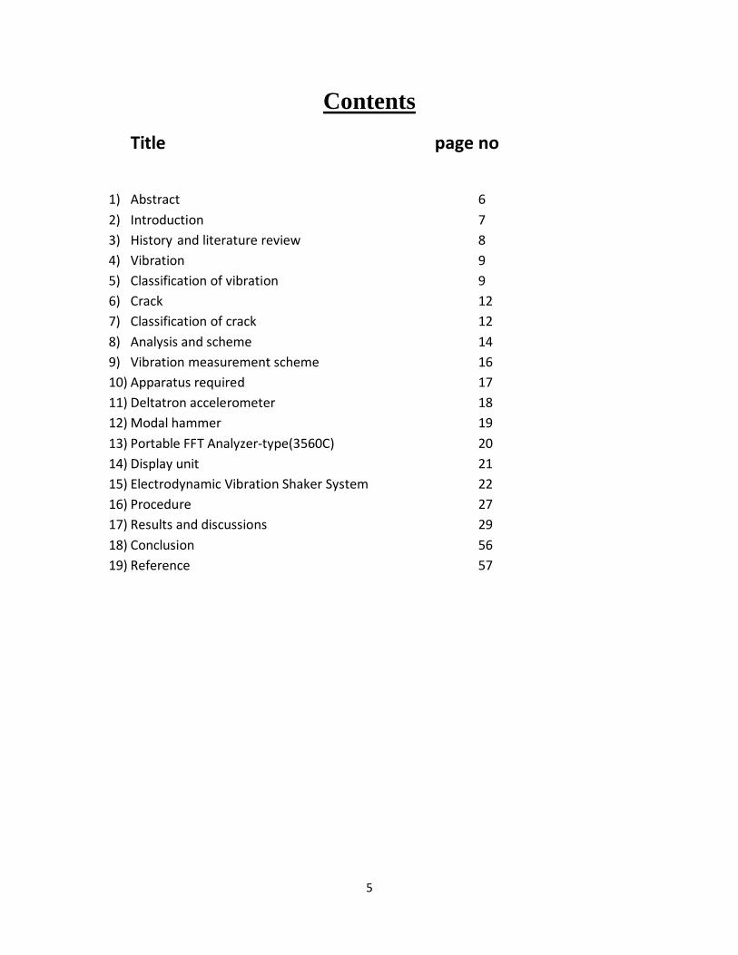
Contents
Title page no
1) Abstract 6
2) Introduction 7
3) History and literature review 8
4) Vibration 9
5) Classification of vibration 9
6) Crack 12
7) Classification of crack 12
8) Analysis and scheme 14
9) Vibration measurement scheme 16
10) Apparatus required 17
11) Deltatron accelerometer 18
12) Modal hammer 19
13) Portable FFT Analyzer-type(3560C) 20
14) Display unit 21
15) Electrodynamic Vibration Shaker System 22
16) Procedure 27
17) Results and discussions 29
18) Conclusion 56
19) Reference 57
6
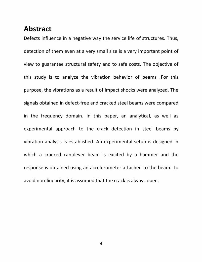
Abstract Defects influence in a negative way the service life of structures. Thus,
detection of them even at a very small size is a very important point of
view to guarantee structural safety and to safe costs. The objective of
this study is to analyze the vibration behavior of beams .For this
purpose, the vibrations as a result of impact shocks were analyzed. The
signals obtained in defect-free and cracked steel beams were compared
in the frequency domain. In this paper, an analytical, as well as
experimental approach to the crack detection in steel beams by
vibration analysis is established. An experimental setup is designed in
which a cracked cantilever beam is excited by a hammer and the
response is obtained using an accelerometer attached to the beam. To
avoid non-linearity, it is assumed that the crack is always open.
7
Introduction
The objective of this study is to analyze the vibration behaviour of beams both experimentally
and using FEM software ANSYS subjected to single and multiple cracks under free and forced
vibration cases. Besides this, information about the location and depth of cracks in cracked
steel beams can be obtained using this technique. Using vibration analysis for early detection of
cracks has gained popularity over the years and in the last decade substantial progress has been
made in that direction. Dynamic characteristics of damaged and undamaged materials are very
different. For this reason, material faults can be detected, especially in steel beams, which are
very important construction elements because of their wide spread usage construction and
machinery. Crack formation due to cycling loads leads to fatigue of the structure and to
discontinuities in the interior configuration. Cracks in vibrating components can initiate
catastrophic failures. Therefore, there is a need to understand the dynamics of cracked
structures. When a structure suffers from damage, its dynamic properties can change.
Specifically, crack damage can cause a stiffness reduction, with an inherent reduction in natural
frequencies, an increase in modal damping, and a change in the mode shapes. From these
changes the crack position and magnitude can be identified. Since the reduction in natural
frequencies can be easily observed, most researchers use this feature. Natural frequency of the
beam has also been determined and verified experimentally. The present project work uses
BRUEL AND KJAER Pulse Analyzer System Type- 3560 and Electrodynamic Vibration
Shaker System for Vibration analysis of cracked steel beams.
8
History and literature review:: The effect of a crack on the deformation of a beam has been considered as an elastic hinge by
Chondros and Dimarogonas(1980) .Variations of the natural frequencies were calculated by a
perturbation method. A finite element model has been proposed , in which two different shape
functions were adopted for two segments of the beam, in order to consider the discontinuity of
deformation due to the crack. Cawley and Adams(1979) showed that the stress distribution in a
vibrating structure was non-uniform and was different for each mode of vibration. Therefore,
any local crack would affect each mode differently, depending on the location of the crack.
Stubbs(1990) and Chondros and Dimarogonas(1998) used the energy method and the
continuous cracked beam theory to analyze transverse vibration of cracked beams. In the
analytical study of this problem, two procedures have been used by researchers to quantify
local flexibility due to the crack. In the first procedure, a stiffness matrix is constructed for the
cracked section, in a similar way as an equivalent spring. In the second procedure which is more
practical, a cracked finite element stiffness matrix is constructed and assembled with the non-
cracked elements of the structure. Dirr and Schmalhorst(1988) used a three dimensional finite
element model with an elastic material to model cracked beams. Qian et al. (1990) formulated
a method of crack detection in beams based on the changes in the natural frequencies and
mode shapes. Narkis(1994) studied the dynamics of a cracked simply supported beam for
bending and axial vibrations. He has shown that for accurate crack identification the variations
of the first two natural frequencies, caused by the crack, are needed. Shen and Pierre(1994)
investigated the vibration of cracked beams with single or symmetrical cracks using Galerkin’s
method with many terms. Nobile invoked equilibrium of elementary beam theory for
9
evaluating the internal forces at the crack tip. Recently, Saavedra and Cuitino (2001) developed
a finite element model for a cracked element to evaluate the dynamic response of a crack-free
beam under harmonic forces. Dilena and Morassi (2002) detected a single crack in a beam
when damage-induced shifts in the mode shapes of the beam are known.
Aim and scope of present study
The objective of this study is to analyze the vibration behaviour of beams both
experimentally and using FEM software ANSYS subjected to single and multiple cracks
under free and forced vibration cases. Besides this, information about the location and
depth of cracks in cracked steel beams can be obtained using this technique.
Theory:
Vibrations: Vibration are time dependent displacements of a particle or a system of
particles w.r.t an equilibrium position. If these displacements are repetitive and their
repetitions are executed at equal interval of time w.r.t equilibrium position the resulting
motion is said to be periodic.
Classification of vibration
Vibration can be classified in several ways. Some of the important classification are as follows :
Free and forced vibration: If a system, after an internal disturbance, is left to vibrate
on its own, the ensuing vibration is known as free vibration. No external force acts on
the system. The oscillation of the simple pendulum is an example of free vibration.
10
If a system is subjected to an external force (often, a repeatating type of force), the
resulting vibration is known as forced vibration. The oscillation that arises in
machineries such as diesel engines is an example of forced vibration.
If the frequency of the external force coincides with one of the natural frequencies of the
system, a condition known as resonance occurs, and the system undergoes dangerously
large oscillations. Failuers of such structures as buildings, bridges, turbines and airplane
have been associated with the occurrence of resonance.
Undamped and damped vibration: If no energy is lost or dissipated in friction or other
resistance during oscillation, the vibration is known as undamped vibration. If any
energy lost in this way, however, it is called damped vibration. In many physical
systems, the amount of damping is so small that it can be disregrated for most
engineering purposes. However, consideration of damping becomes extermely
important in analyzing vibratory system near resonance.
Linear and nonlinear vibration : If all the basic components of vibratory system—the
spring, the mass and the damper—behave lineraly, the resulting vibration is known as
linear vibration.if ,however,any af the basic components behave non linearly, the
vibration is called non linear vibration.
IMPORTANCE OF VIBRATION
The increasing demands of high productivity and economical design led to higher
operation speeds of machinery and efficient use of materials through light weight
11
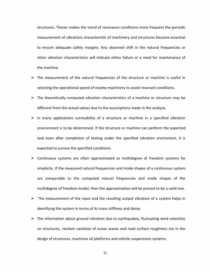
structures. Theses makes the trend of resonance conditions more frequent the periodic
measurement of vibrations characteristic of machinery and structures become essential
to ensure adequate safety margins. Any observed shift in the natural frequencies or
other vibration characteristics will indicate either failure or a need for maintenance of
the machine.
The measurement of the natural frequencies of the structure or machine is useful in
selecting the operational speed of nearby machinery to avoid resonant conditions.
The theoretically computed vibration characteristics of a machine or structure may be
different from the actual values due to the assumptions made in the analysis.
In many applications survivability of a structure or machine in a specified vibration
environment is to be determined. If the structure or machine can perform the expected
task even after completion of testing under the specified vibration enviroment, it is
expected to survive the specified conditions.
Continuous systems are often approximated as multidegree of freedom systems for
simplicity .If the measured natural frequencies and mode shapes of a continuous system
are comparable to the computed natural frequencies and mode shapes of the
multidegree of freedom model, then the approximation will be proved to be a valid one.
The measurement of the input and the resulting output vibration of a system helps in
identifying the system in terms of its mass stiffness and damp.
The information about ground vibration due to earthquakes, fluctuating wind velocities
on structures, random variation of ocean waves and road surface roughness are in the
design of structures, machines oil platforms and vehicle suspensions systems.
12
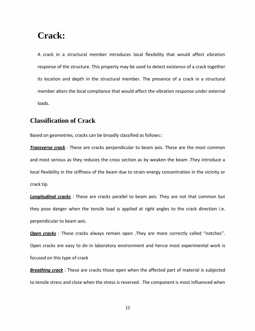
Crack:
A crack in a structural member introduces local flexibility that would affect vibration
response of the structure. This property may be used to detect existence of a crack together
its location and depth in the structural member. The presence of a crack in a structural
member alters the local compliance that would affect the vibration response under external
loads.
Classification of Crack
Based on geometries, cracks can be broadly classified as follows::
Transverse crack : These are cracks perpendicular to beam axis. These are the most common
and most serious as they reduces the cross section as by weaken the beam .They introduce a
local flexibility in the stiffness of the beam due to strain energy concentration in the vicinity or
crack tip.
Longitudinal cracks : These are cracks parallel to beam axis. They are not that common but
they pose danger when the tensile load is applied at right angles to the crack direction i.e.
perpendicular to beam axis.
Open cracks : These cracks always remain open .They are more correctly called “notches”.
Open cracks are easy to do in laboratory environment and hence most experimental work is
focused on this type of crack
Breathing crack : These are cracks those open when the affected part of material is subjected
to tensile stress and close when the stress is reversed . The component is most influenced when
13
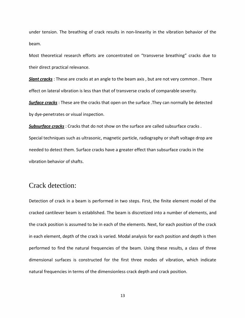
under tension. The breathing of crack results in non‐linearity in the vibration behavior of the
beam.
Most theoretical research efforts are concentrated on “transverse breathing” cracks due to
their direct practical relevance.
Slant cracks : These are cracks at an angle to the beam axis , but are not very common . There
effect on lateral vibration is less than that of transverse cracks of comparable severity.
Surface cracks : These are the cracks that open on the surface .They can normally be detected
by dye‐penetrates or visual inspection.
Subsurface cracks : Cracks that do not show on the surface are called subsurface cracks .
Special techniques such as ultrasonic, magnetic particle, radiography or shaft voltage drop are
needed to detect them. Surface cracks have a greater effect than subsurface cracks in the
vibration behavior of shafts.
Crack detection:
Detection of crack in a beam is performed in two steps. First, the finite element model of the
cracked cantilever beam is established. The beam is discretized into a number of elements, and
the crack position is assumed to be in each of the elements. Next, for each position of the crack
in each element, depth of the crack is varied. Modal analysis for each position and depth is then
performed to find the natural frequencies of the beam. Using these results, a class of three
dimensional surfaces is constructed for the first three modes of vibration, which indicate
natural frequencies in terms of the dimensionless crack depth and crack position.
14
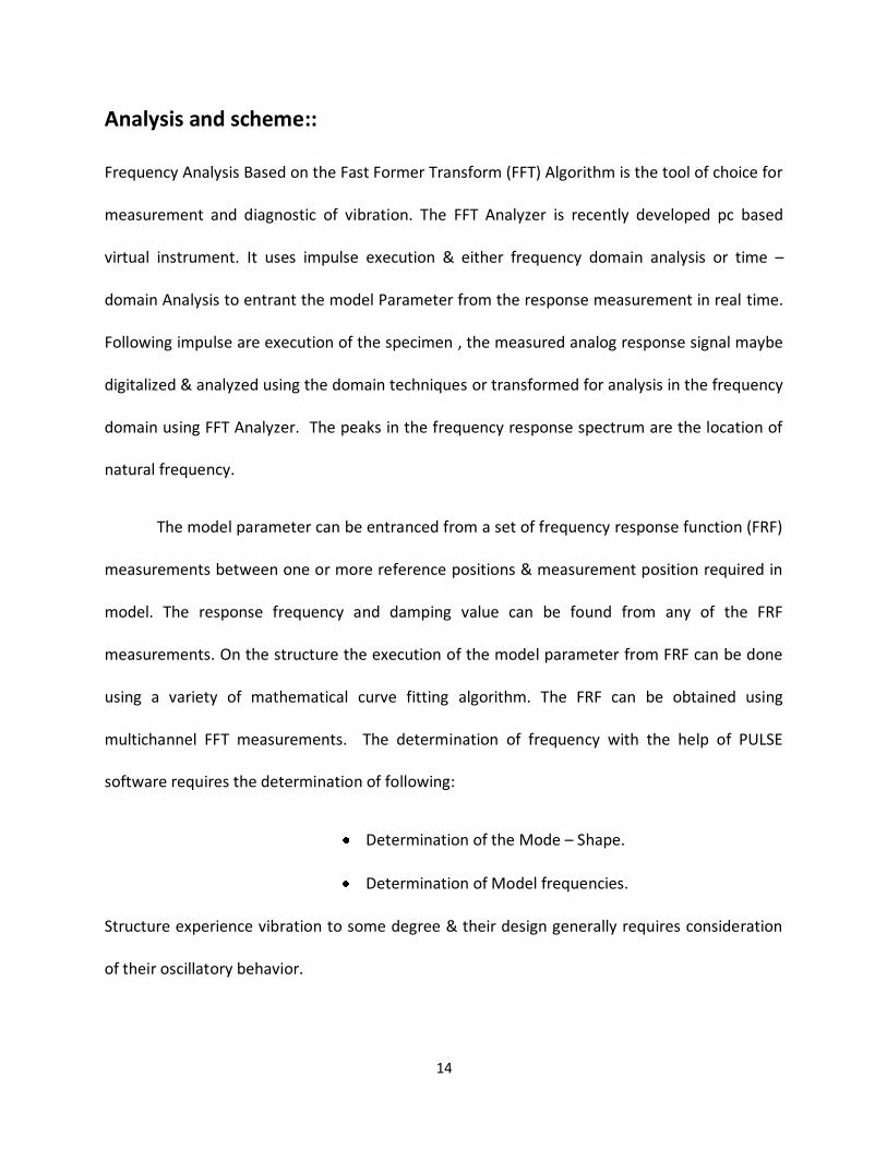
Analysis and scheme::
Frequency Analysis Based on the Fast Former Transform (FFT) Algorithm is the tool of choice for
measurement and diagnostic of vibration. The FFT Analyzer is recently developed pc based
virtual instrument. It uses impulse execution & either frequency domain analysis or time –
domain Analysis to entrant the model Parameter from the response measurement in real time.
Following impulse are execution of the specimen , the measured analog response signal maybe
digitalized & analyzed using the domain techniques or transformed for analysis in the frequency
domain using FFT Analyzer. The peaks in the frequency response spectrum are the location of
natural frequency.
The model parameter can be entranced from a set of frequency response function (FRF)
measurements between one or more reference positions & measurement position required in
model. The response frequency and damping value can be found from any of the FRF
measurements. On the structure the execution of the model parameter from FRF can be done
using a variety of mathematical curve fitting algorithm. The FRF can be obtained using
multichannel FFT measurements. The determination of frequency with the help of PULSE
software requires the determination of following:
Determination of the Mode – Shape.
Determination of Model frequencies.
Structure experience vibration to some degree & their design generally requires consideration
of their oscillatory behavior.
15
In the practice nearly all vibration problems are related to structural weakness, associated with
response behavior (that is natural frequencies being excited by operational forces) it can be
shown that completely dynamic behavior of a structure (in a given frequency range) can be
viewed as a set of individual model of vibration, each having a characteristic natural frequency,
damping of mode shape.
16
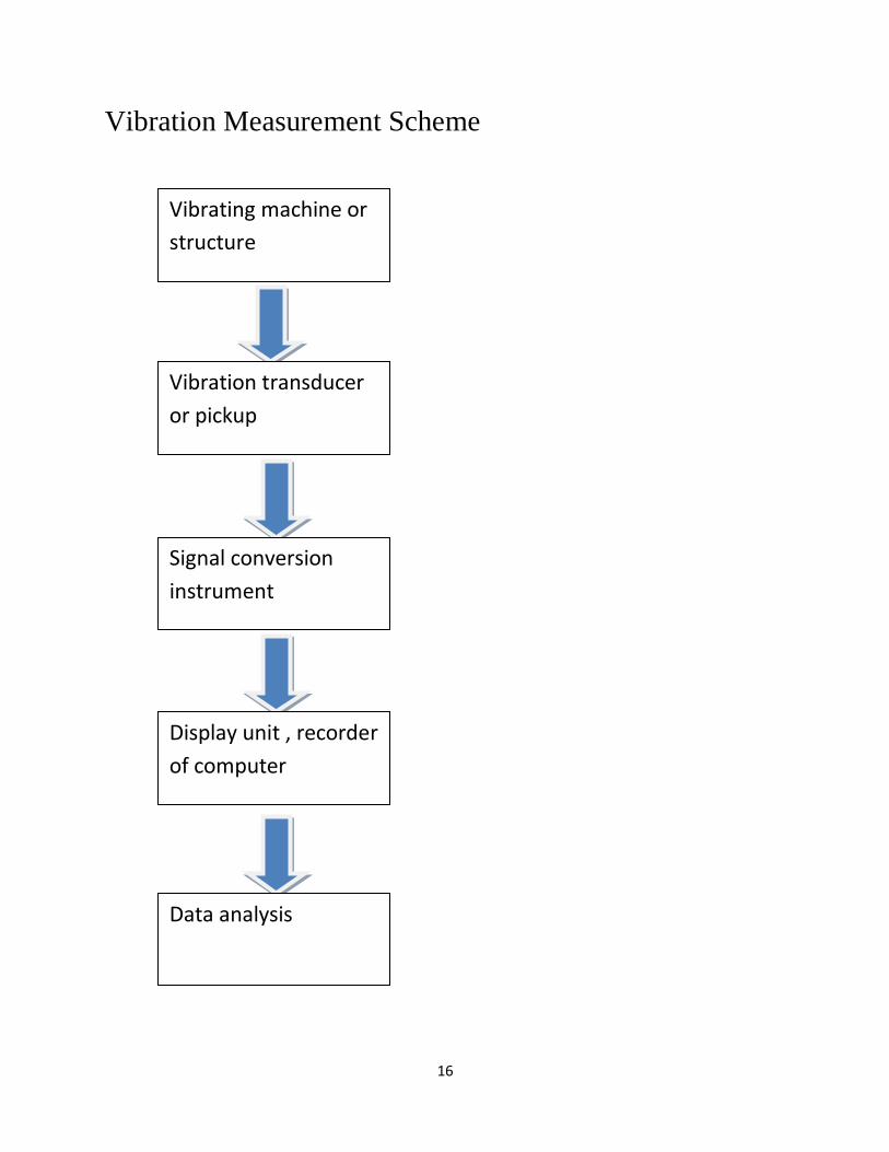
Vibration Measurement Scheme
Vibrating machine or
structure
Vibration transducer
or pickup
Signal conversion
instrument
Display unit , recorder
of computer
Data analysis
17
Apparatus Required:
Model hammer.
Accelerometer.
FFT Analyser.
Notebook with PULSE software.
Electrodynamic vibration shaker system
Power amplifier cum signal generator
Vibration table
Specimen
18
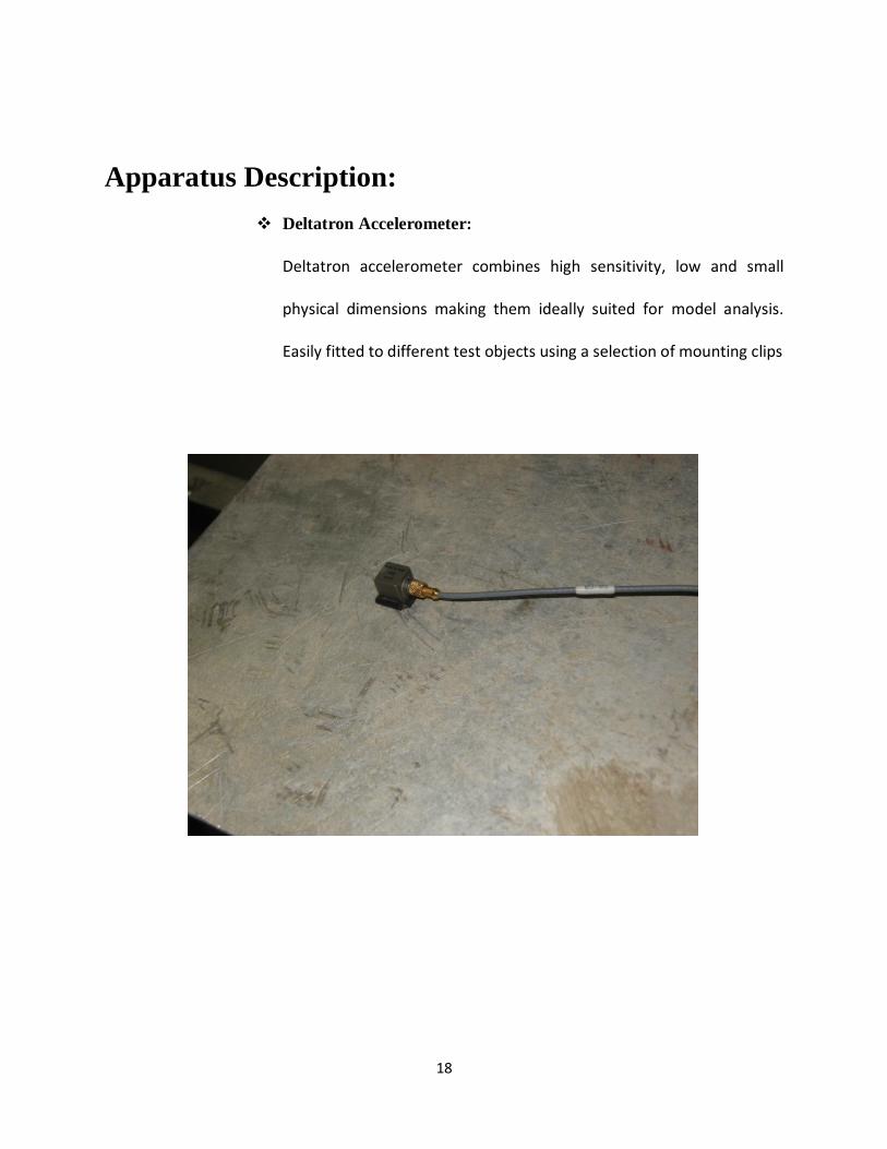
Apparatus Description:
Deltatron Accelerometer:
Deltatron accelerometer combines high sensitivity, low and small
physical dimensions making them ideally suited for model analysis.
Easily fitted to different test objects using a selection of mounting clips
19
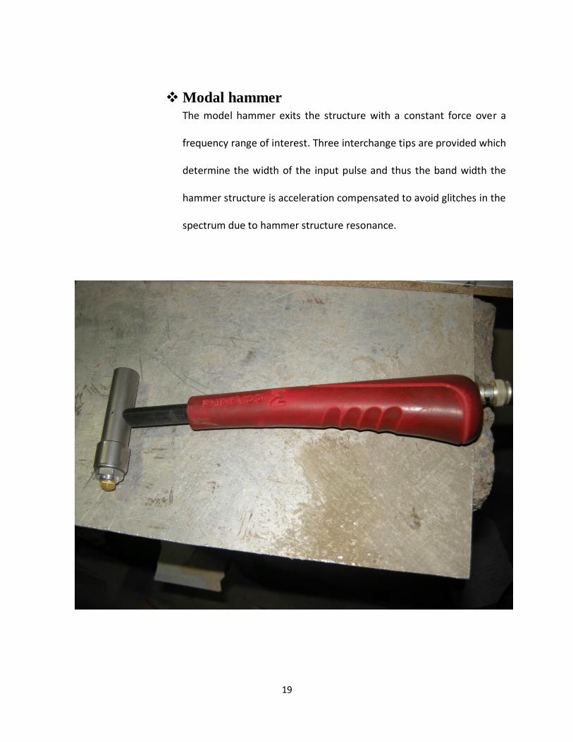
Modal hammer The model hammer exits the structure with a constant force over a
frequency range of interest. Three interchange tips are provided which
determine the width of the input pulse and thus the band width the
hammer structure is acceleration compensated to avoid glitches in the
spectrum due to hammer structure resonance.
20
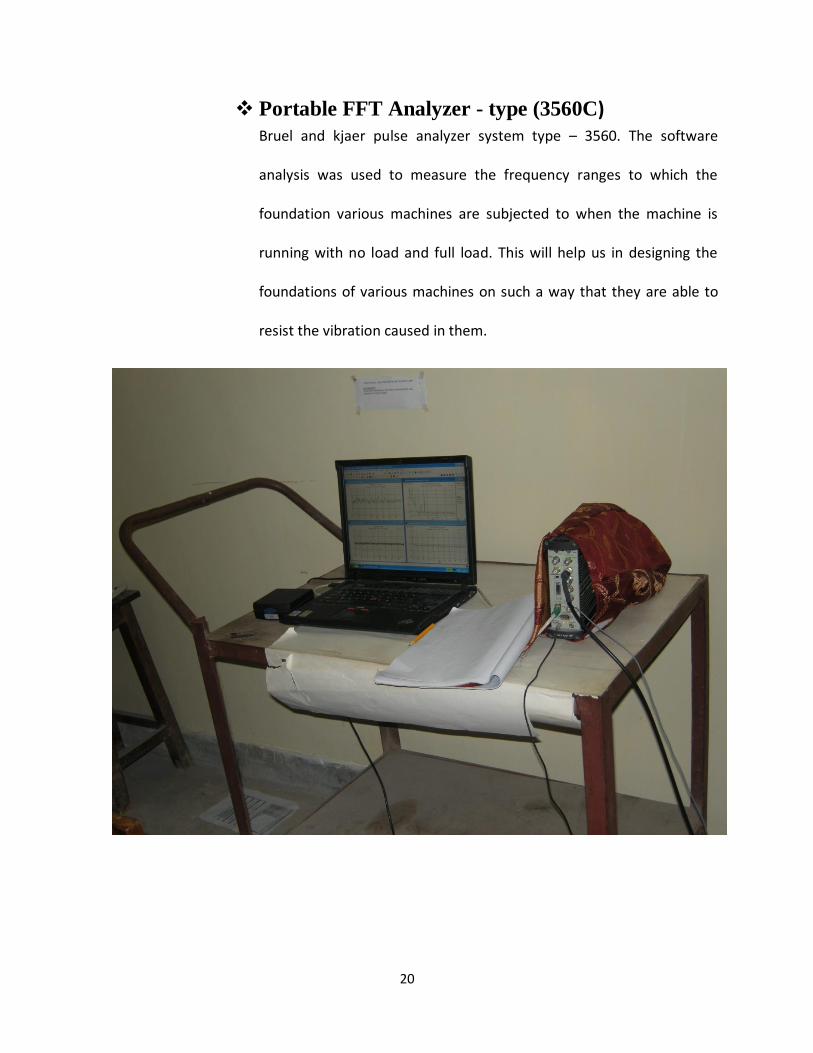
Portable FFT Analyzer - type (3560C) Bruel and kjaer pulse analyzer system type – 3560. The software
analysis was used to measure the frequency ranges to which the
foundation various machines are subjected to when the machine is
running with no load and full load. This will help us in designing the
foundations of various machines on such a way that they are able to
resist the vibration caused in them.
21
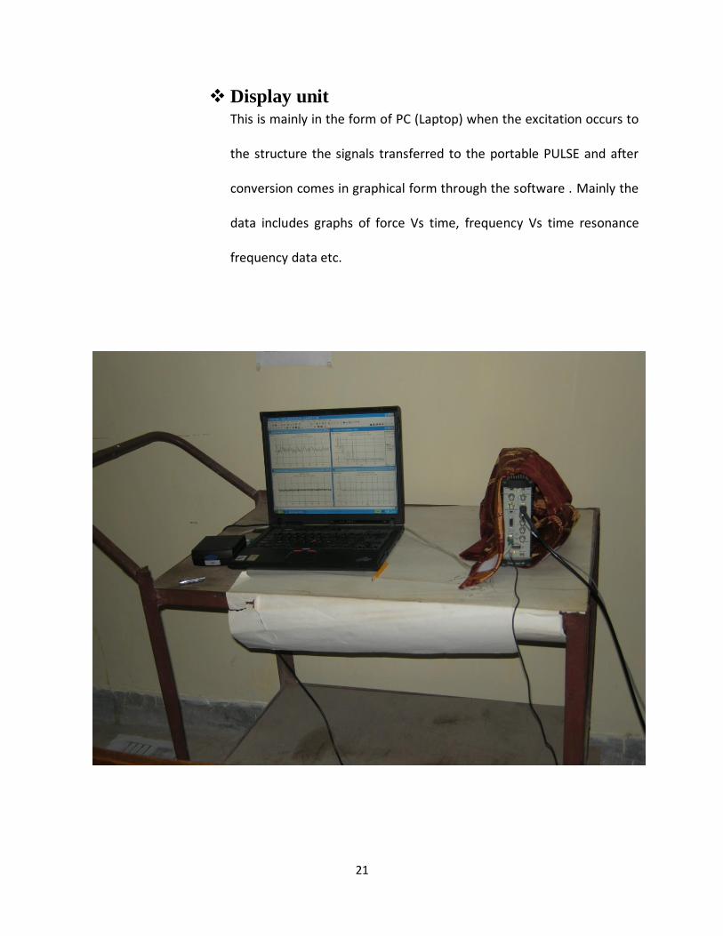
Display unit This is mainly in the form of PC (Laptop) when the excitation occurs to
the structure the signals transferred to the portable PULSE and after
conversion comes in graphical form through the software . Mainly the
data includes graphs of force Vs time, frequency Vs time resonance
frequency data etc.
22
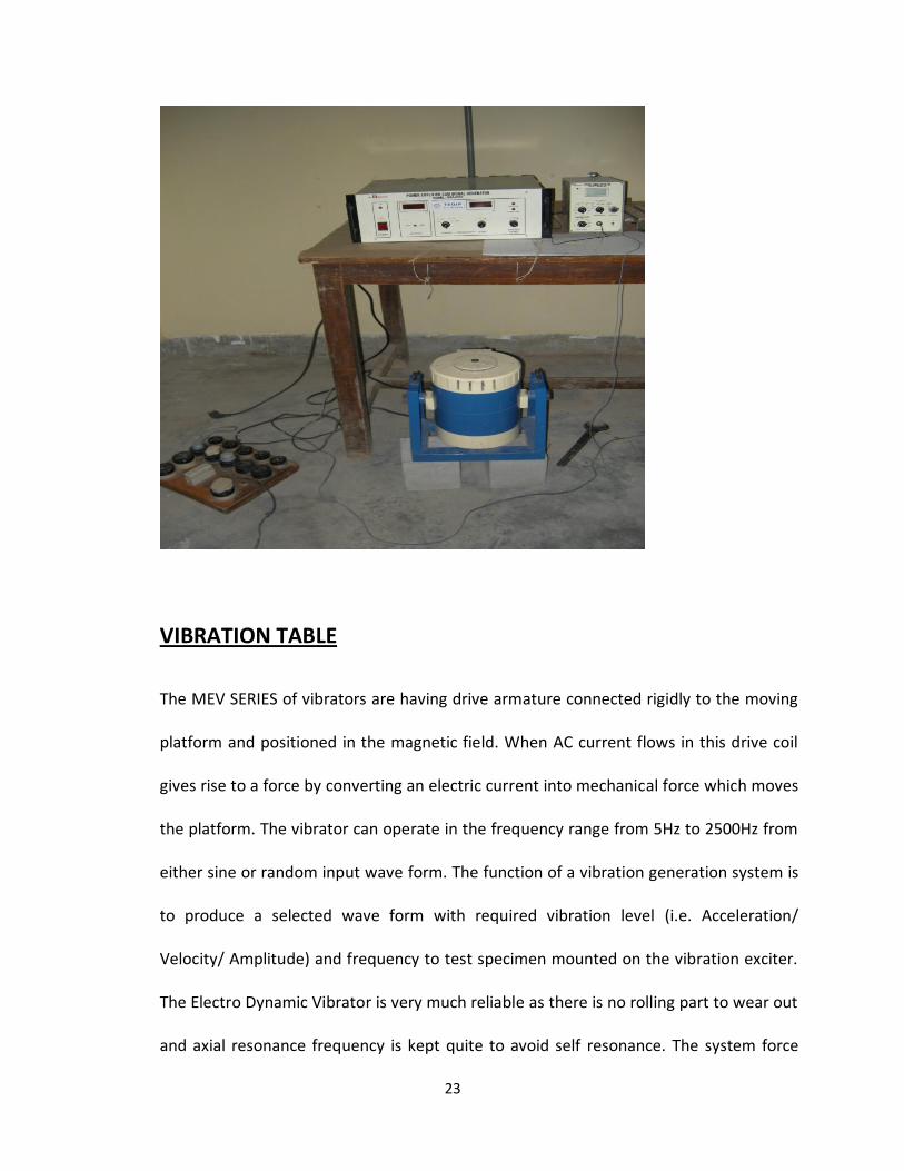
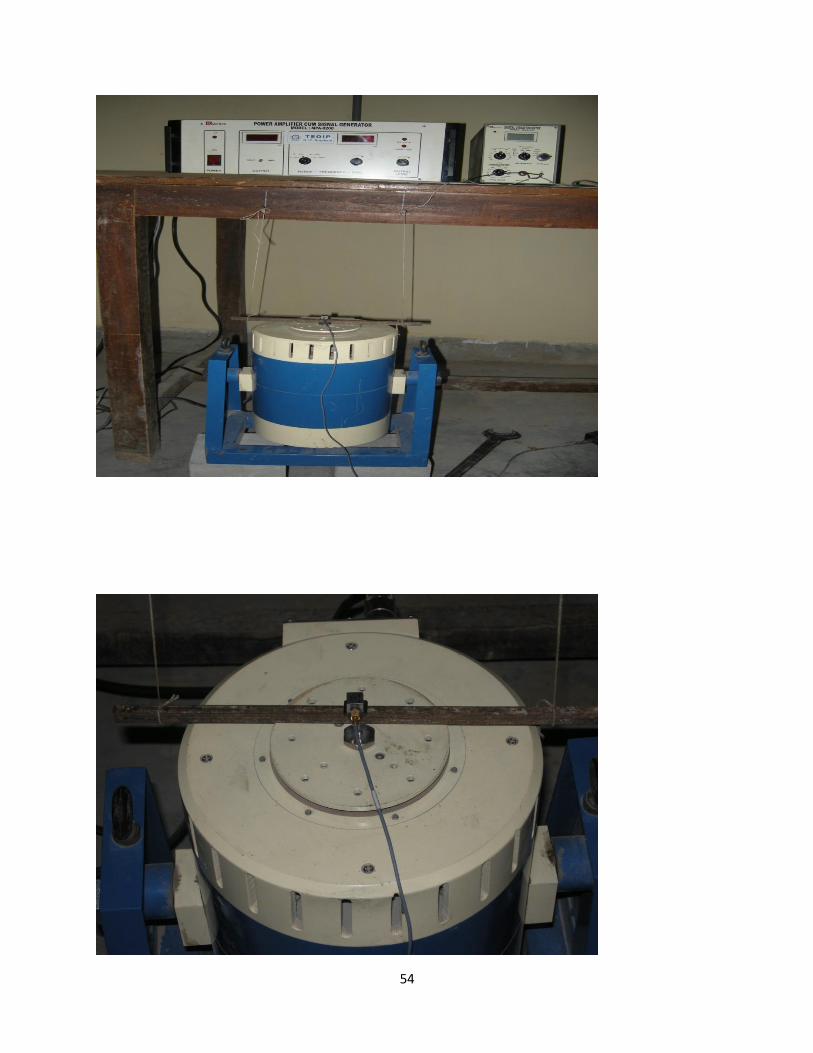
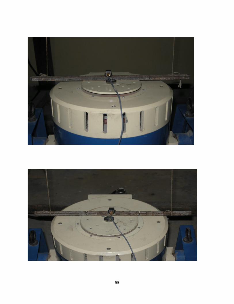
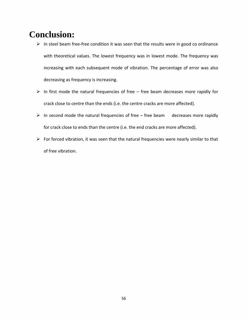
ELECTRODYNAMIC VIBRATION SHAKER SYSTEM
SYSTEM DESCRIPTION
MEV system is developed with indigenous design and manufacture for dynamic testing to
determine the fundamental physical properties of materials and products. We experienced in
the indigenous manufacture of mechanical vibrators, transducers, data acquisition system,
centrifuge machine and close loop Electro Dynamic techniques etc.
The series of MEV vibration system are the result of long experience in the design and
manufacture of test system. It assists the user in determining the safety, reliability, durability
and resonance frequency of the product.
A vibration test system consists of a signal generator, a power amplifier and vibration exciter.
ELECTRODYNAMIC VIBRATION SHAKER SYSTEM CONSISTS THE
FOLLOWING ITEMS:-
1. VIBRATION TABLE
2. POWER AMPLIFIER CUM SIGNAL GENERATOR
23
VIBRATION TABLE
The MEV SERIES of vibrators are having drive armature connected rigidly to the moving
platform and positioned in the magnetic field. When AC current flows in this drive coil
gives rise to a force by converting an electric current into mechanical force which moves
the platform. The vibrator can operate in the frequency range from 5Hz to 2500Hz from
either sine or random input wave form. The function of a vibration generation system is
to produce a selected wave form with required vibration level (i.e. Acceleration/
Velocity/ Amplitude) and frequency to test specimen mounted on the vibration exciter.
The Electro Dynamic Vibrator is very much reliable as there is no rolling part to wear out
and axial resonance frequency is kept quite to avoid self resonance. The system force
24
rating and moving element mass are the primary characteristics which determine the
vibration level.
SALIENT FEATURES
Long term reliability
Link arm suspension system
Excellent cross-axial restraint
Dual suspension system
SPECIFICATIONS
Model : MEV 0020
PEAK Sine Force : ±20 Kgf (±200N)
Max. Displacement : 10 mm (pk-pk)
Frequency Range : 5 Hz to 2500 Hz (Within 0.1 db)
1st Major Armature resonance : >2.5 Kg
Max. Payload : 2.5 Kg
Shaker Rotation : ±90 kg degree from vertical
Drive power : Thru a solid state Power Amplifier cum
Signal Generator
25
Cooling Method : Integral fan cooled
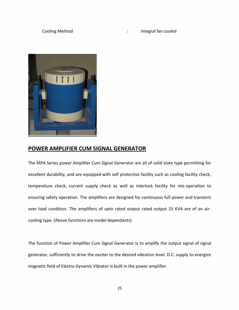
POWER AMPLIFIER CUM SIGNAL GENERATOR The MPA Series power Amplifier Cum Signal Generator are all of solid state type permitting for
excellent durability, and are equipped with self protective facility such as cooling facility check,
temperature check, current supply check as well as interlock facility for mis-operation to
ensuring safety operation. The amplifiers are designed for continuous full power and transient
over load condition. The amplifiers of upto rated output rated output 15 KVA are of an air-
cooling type. (Above functions are model dependants)
The function of Power Amplifier Cum Signal Generator is to amplify the output signal of signal
generator, sufficiently to drive the exciter to the desired vibration level. D.C. supply to energize
magnetic field of Electro Dynamic Vibrator is built in the power amplifier.
26
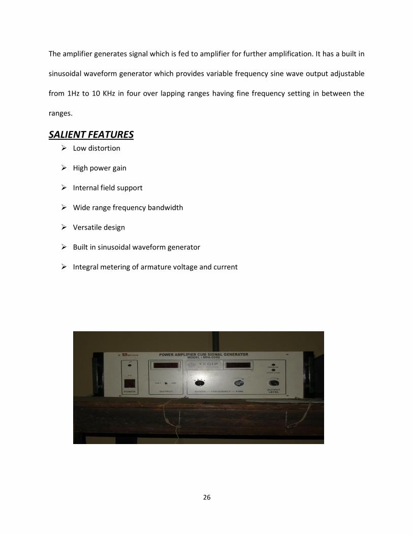
The amplifier generates signal which is fed to amplifier for further amplification. It has a built in
sinusoidal waveform generator which provides variable frequency sine wave output adjustable
from 1Hz to 10 KHz in four over lapping ranges having fine frequency setting in between the
ranges.
SALIENT FEATURES Low distortion
High power gain
Internal field support
Wide range frequency bandwidth
Versatile design
Built in sinusoidal waveform generator
Integral metering of armature voltage and current
27
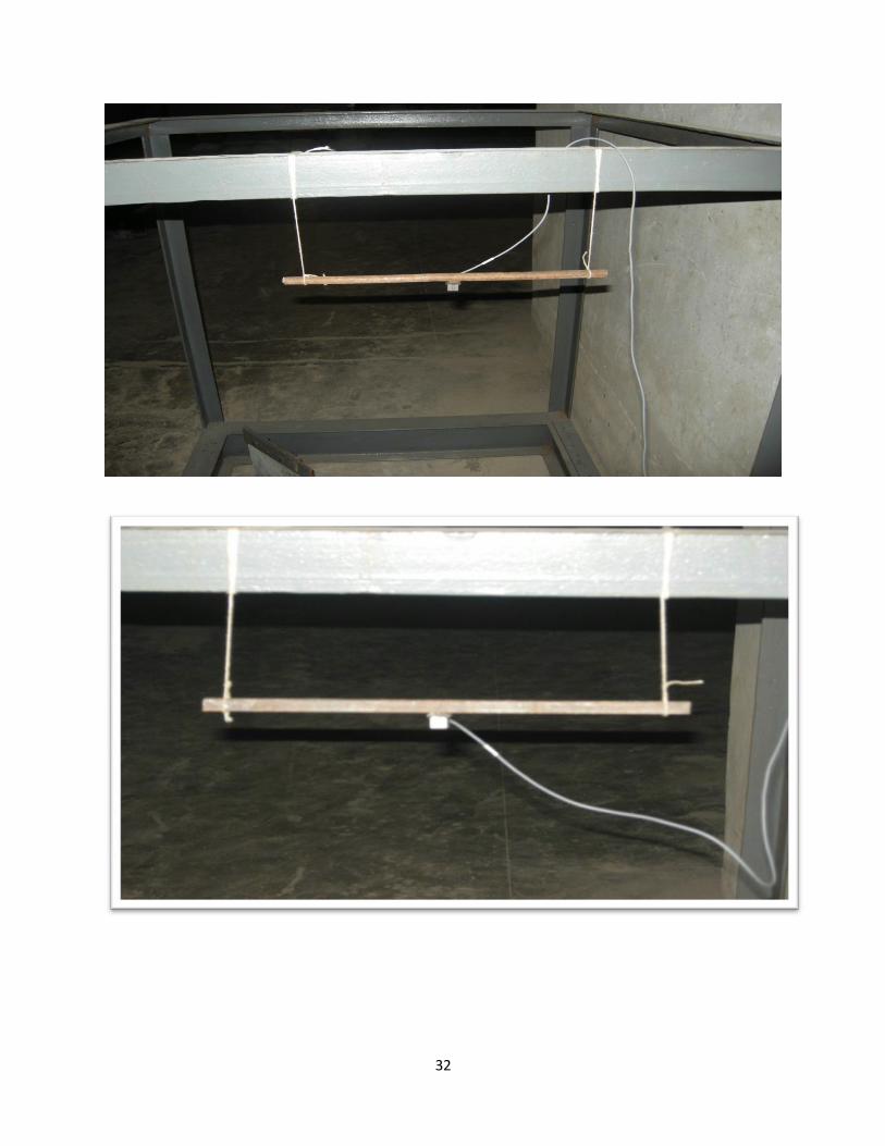
Procedure :
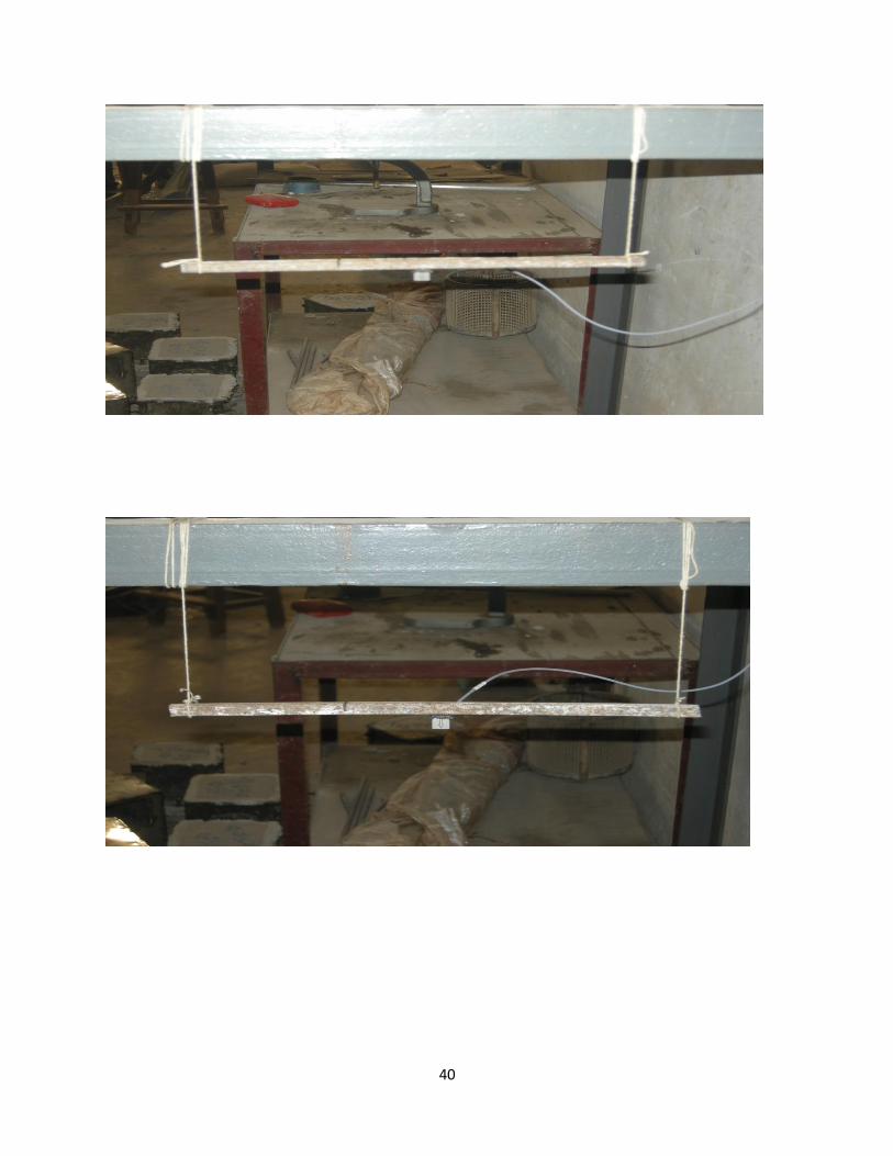
The connections i.e accelerometer, modal hammer, laptop and other power
connections were made.
The surface of the beam was cleaned for proper contact with the accelerometer.
The accelerometer was then attached with the surface of the beam.
The above connections were made for free vibrations.
For Forced Vibration, Electrodynamic Vibration Shaker System was used which consist of
Vibration Table and Power Amplifier Cum Signal Generator.
Readings were taken for free-free and fixed-free boundary conditions for different steel
beams.
The modal analysis results are compared with FEM package ANSYS and analytical values.
28
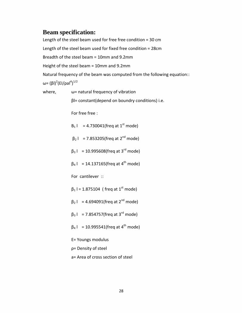
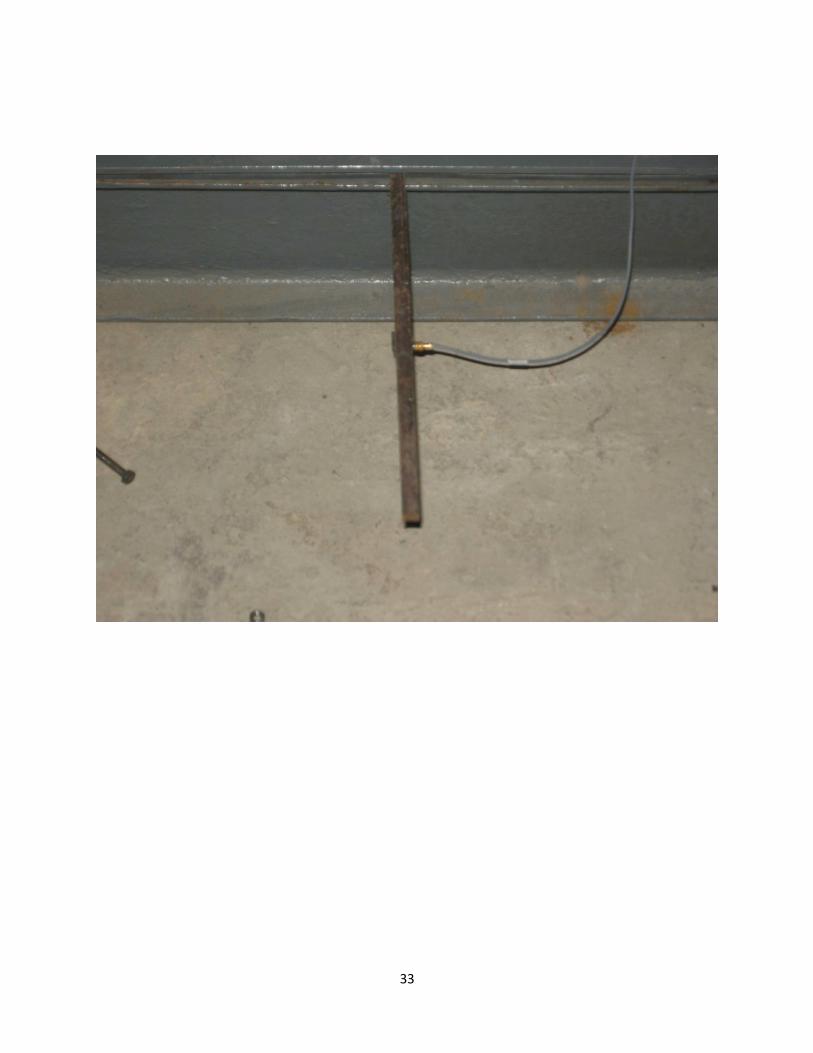
Beam specification: Length of the steel beam used for free free condition = 30 cm
Length of the steel beam used for fixed free condition = 28cm
Breadth of the steel beam = 10mm and 9.2mm
Height of the steel beam = 10mm and 9.2mm
Natural frequency of the beam was computed from the following equation::
ω= (βl)2(EI/ρal4)1/2
where, ω= natural frequency of vibration
βl= constant(depend on boundry conditions) i.e.
For free free :
Β1 l = 4.730041(freq at 1st mode)
β2 l = 7.853205(freq at 2nd mode)
β3 l = 10.995608(freq at 3rd mode)
β4 l = 14.137165(freq at 4th mode)
For cantilever ::
β1 l = 1.875104 ( freq at 1st mode)
β2 l = 4.694091(freq at 2nd mode)
β3 l = 7.854757(freq at 3rd mode)
β4 l = 10.995541(freq at 4th mode)
E= Youngs modulus
ρ= Density of steel
a= Area of cross section of steel
29
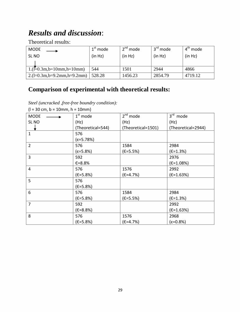
Results and discussion: Theoretical results:
MODE
SL NO
1st mode
(in Hz)
2nd mode
(in Hz)
3rd mode
(in Hz)
4th mode
(in Hz)
1.(l=0.3m,b=10mm,h=10mm) 544 1501 2944 4866
2.(l=0.3m,b=9.2mm,h=9.2mm) 528.28 1456.23 2854.79 4719.12
Comparison of experimental with theoretical results:
Steel (uncracked ,free-free boundry condition):
(l = 30 cm, b = 10mm, h = 10mm)
MODE SL NO
1st mode (Hz) (Theoretical=544)
2nd mode (Hz) (Theoretical=1501)
3rd mode (Hz) (Theoretical=2944)
1 576 (є=5.78%)
2 576 (є=5.8%)
1584 (Є=5.5%)
2984 (Є=1.3%)
3 592 Є=8.8%
2976 (Є=1.08%)
4 576 (Є=5.8%)
1576 (Є=4.7%)
2992 (Є=1.63%)
5 576 (Є=5.8%)
6 576 (Є=5.8%)
1584 (Є=5.5%)
2984 (Є=1.3%)
7 592 (Є=8.8%)
2992 (Є=1.63%)
8 576 (Є=5.8%)
1576 (Є=4.7%)
2968 (є=0.8%)
30
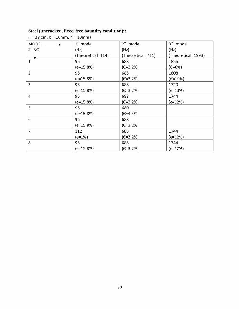
Steel (uncracked, fixed-free boundry condition)::
(l = 28 cm, b = 10mm, h = 10mm)
MODE SL NO
1st mode (Hz) (Theoretical=114)
2nd mode (Hz) (Theoretical=711)
3rd mode (Hz) (Theoretical=1993)
1 96 (є=15.8%)
688 (Є=3.2%)
1856 (Є=6%)
2 96 (є=15.8%)
688 (Є=3.2%)
1608 (Є=19%)
3 96 (є=15.8%)
688 (Є=3.2%)
1720 (є=13%)
4 96 (є=15.8%)
688 (Є=3.2%)
1744 (є=12%)
5 96 (є=15.8%)
680 (Є=4.4%)
6 96 (є=15.8%)
688 (Є=3.2%)
7 112 (є=1%)
688 (Є=3.2%)
1744 (є=12%)
8 96 (є=15.8%)
688 (Є=3.2%)
1744 (є=12%)
31
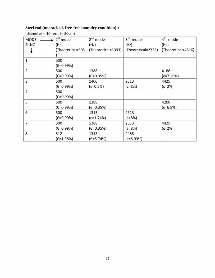
Steel rod (uncracked, free-free boundry condition)::
(diameter = 10mm , l= 30cm)
MODE SL NO
1st mode (Hz) (Theoretical=505)
2nd mode (Hz) (Theoretical=1393)
3rd mode (Hz) (Theoretical=2732)
4th mode (Hz) (Theoretical=4516)
1 500 (Є=0.99%)
2 500 (Є=0.99%)
1388 (Є=0.35%)
4188 (є=7.26%)
3 500 (Є=0.99%)
1400 (є=0.5%)
2513 (є=8%)
4425 (є=2%)
4 500 (Є=0.99%)
5 500 (Є=0.99%)
1388 (Є=0.35%)
4200 (є=6.9%)
6 500 (Є=0.99%)
1313 (є=1.74%)
2513 (є=8%)
7 500 (Є=0.99%)
1388 (Є=0.35%)
2513 (є=8%)
4425 (є=2%)
8 512 (Є=1.38%)
1313 (Є=5.74%)
2488 (є=8.93%)
32
33
34
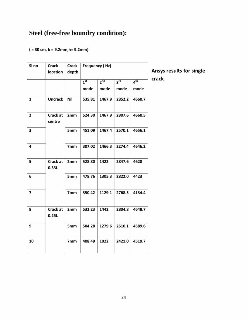
Steel (free-free boundry condition):
(l= 30 cm, b = 9.2mm,h= 9.2mm)
Ansys results for single
crack
Sl no Crack
location
Crack
depth
Frequency ( Hz)
1st
mode
2nd
mode
3rd
mode
4th
mode
1 Uncrack Nil 535.81 1467.9 2852.2 4660.7
2 Crack at
centre
2mm 524.30 1467.9 2807.6 4660.5
3 5mm 451.09 1467.4 2570.1 4656.1
4 7mm 307.02 1466.3 2274.4 4646.2
5 Crack at
0.33L
2mm 528.80 1422 2847.6 4628
6 5mm 478.76 1305.3 2822.0 4423
7 7mm 350.42 1129.1 2768.5 4134.4
8 Crack at
0.25L
2mm 532.23 1442 2804.8 4648.7
9 5mm 504.28 1279.6 2610.1 4589.6
10 7mm 408.49 1022 2421.0 4519.7
35
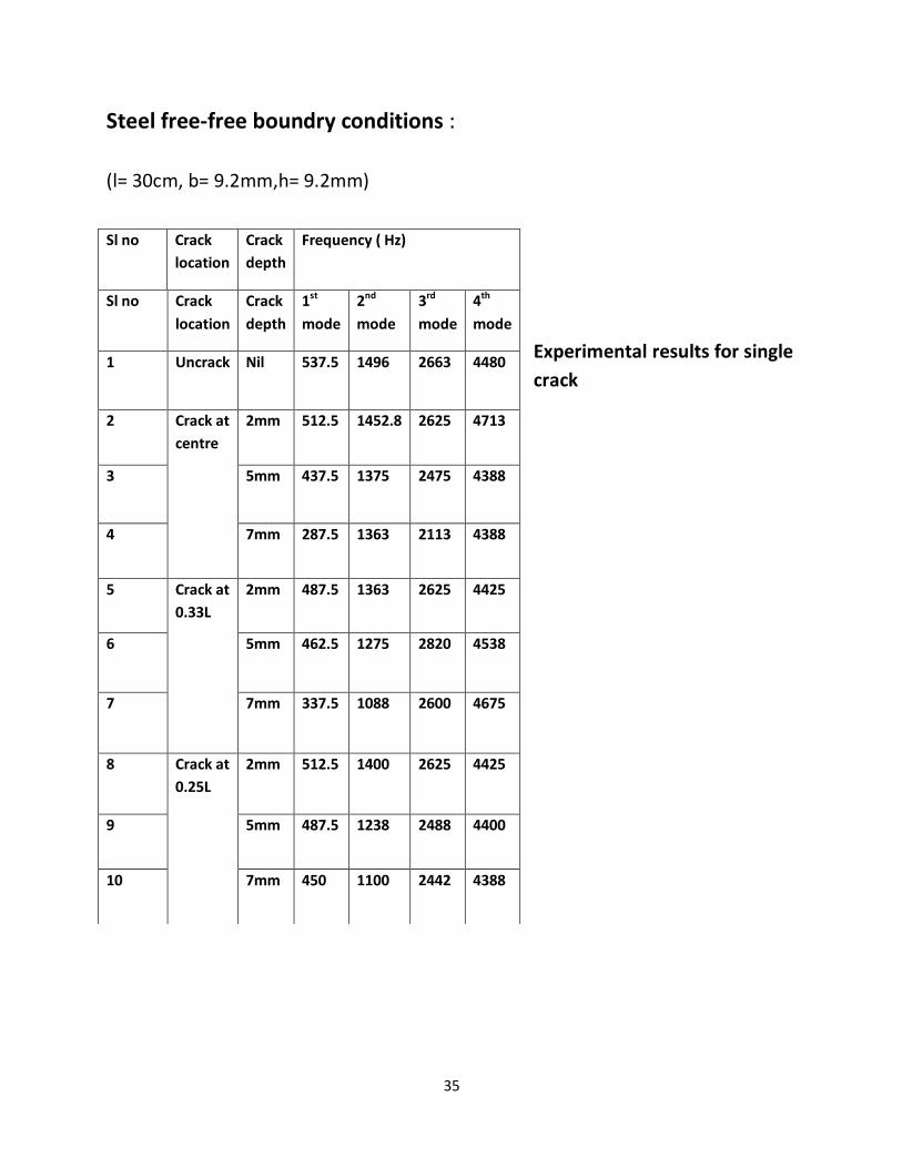
Steel free-free boundry conditions :
(l= 30cm, b= 9.2mm,h= 9.2mm)
Experimental results for single
crack
Sl no Crack
location
Crack
depth
Frequency ( Hz)
Sl no Crack
location
Crack
depth
1st
mode
2nd
mode
3rd
mode
4th
mode
1 Uncrack Nil 537.5 1496 2663 4480
2 Crack at
centre
2mm 512.5 1452.8 2625 4713
3 5mm 437.5 1375 2475 4388
4 7mm 287.5 1363 2113 4388
5 Crack at
0.33L
2mm 487.5 1363 2625 4425
6 5mm 462.5 1275 2820 4538
7 7mm 337.5 1088 2600 4675
8 Crack at
0.25L
2mm 512.5 1400 2625 4425
9 5mm 487.5 1238 2488 4400
10 7mm 450 1100 2442 4388
36
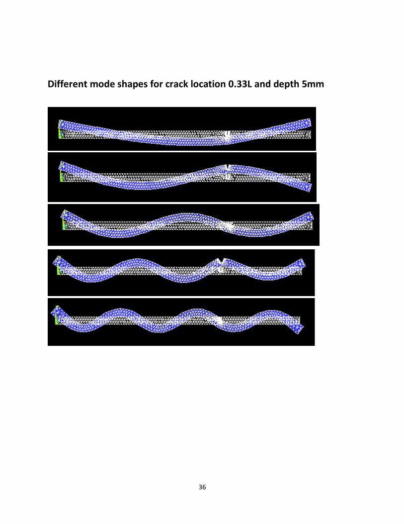
Different mode shapes for crack location 0.33L and depth 5mm
37
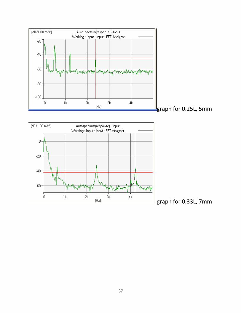
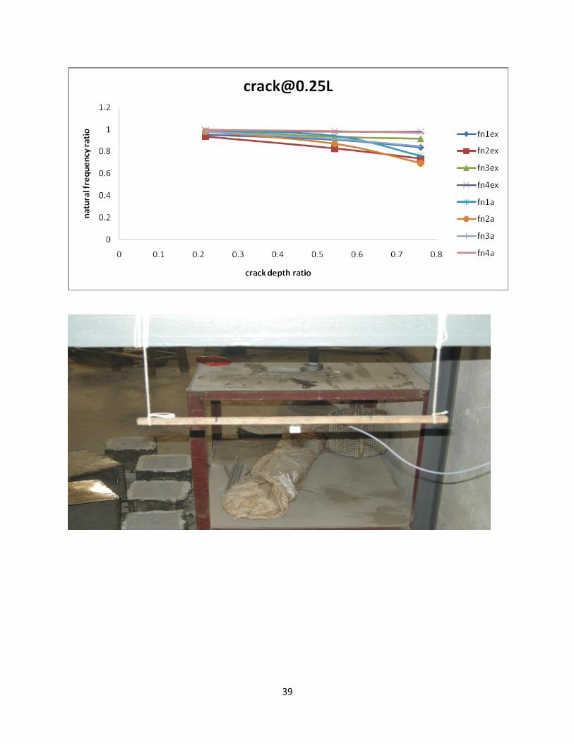
graph for 0.25L, 5mm
graph for 0.33L, 7mm
38
39
40
41
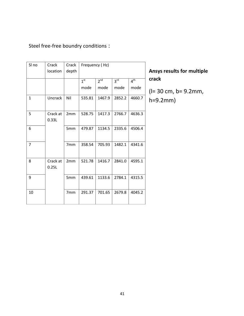
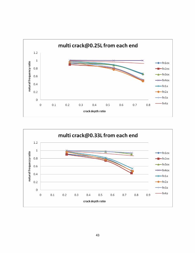
Steel free-free boundry conditions :
Ansys results for multiple
crack
(l= 30 cm, b= 9.2mm,
h=9.2mm)
Sl no Crack
location
Crack
depth
Frequency ( Hz)
1st
mode
2nd
mode
3rd
mode
4th
mode
1 Uncrack Nil 535.81 1467.9 2852.2 4660.7
5 Crack at
0.33L
2mm 528.75 1417.3 2766.7 4636.3
6 5mm 479.87 1134.5 2335.6 4506.4
7 7mm 358.54 705.93 1482.1 4341.6
8 Crack at
0.25L
2mm 521.78 1416.7 2841.0 4595.1
9 5mm 439.61 1133.6 2784.1 4315.5
10 7mm 291.37 701.65 2679.8 4045.2
42
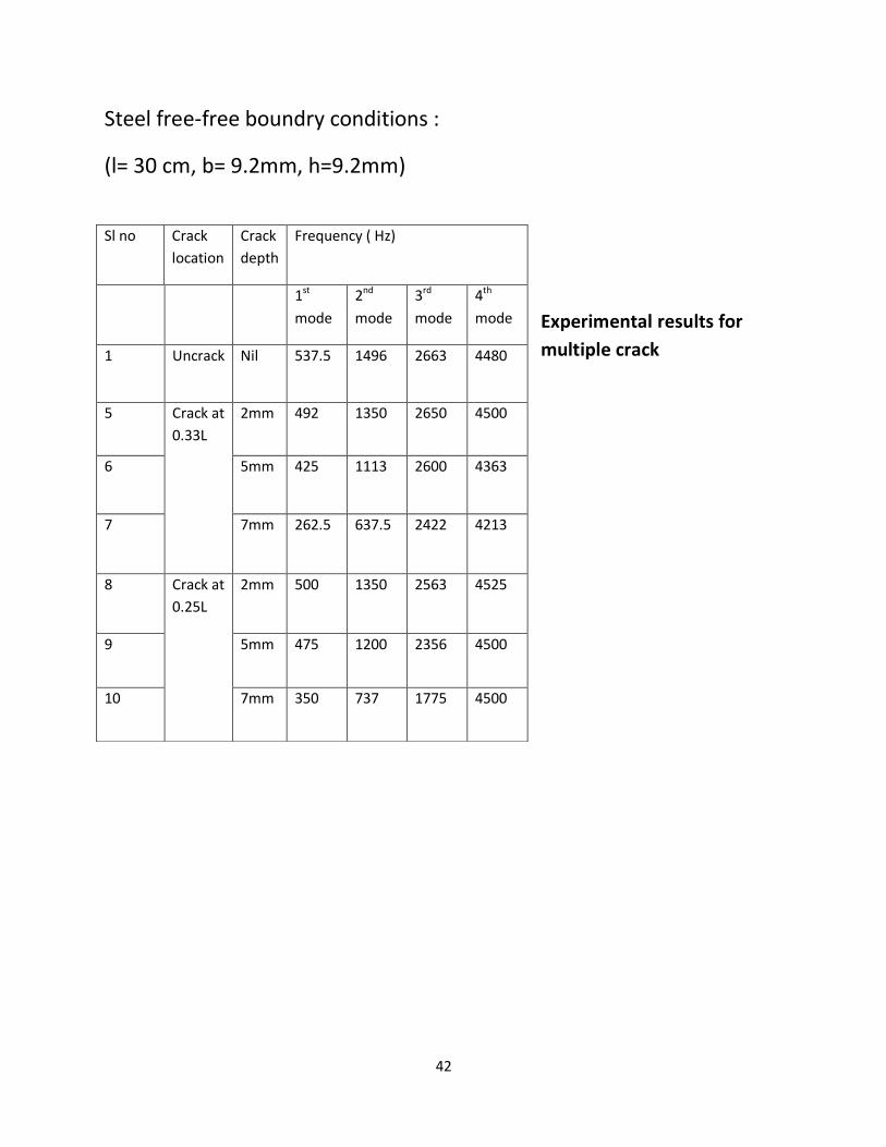
Steel free-free boundry conditions :
(l= 30 cm, b= 9.2mm, h=9.2mm)
Experimental results for
multiple crack
Sl no Crack
location
Crack
depth
Frequency ( Hz)
1st
mode
2nd
mode
3rd
mode
4th
mode
1 Uncrack Nil 537.5 1496 2663 4480
5 Crack at
0.33L
2mm 492 1350 2650 4500
6 5mm 425 1113 2600 4363
7 7mm 262.5 637.5 2422 4213
8 Crack at
0.25L
2mm 500 1350 2563 4525
9 5mm 475 1200 2356 4500
10 7mm 350 737 1775 4500
43
44
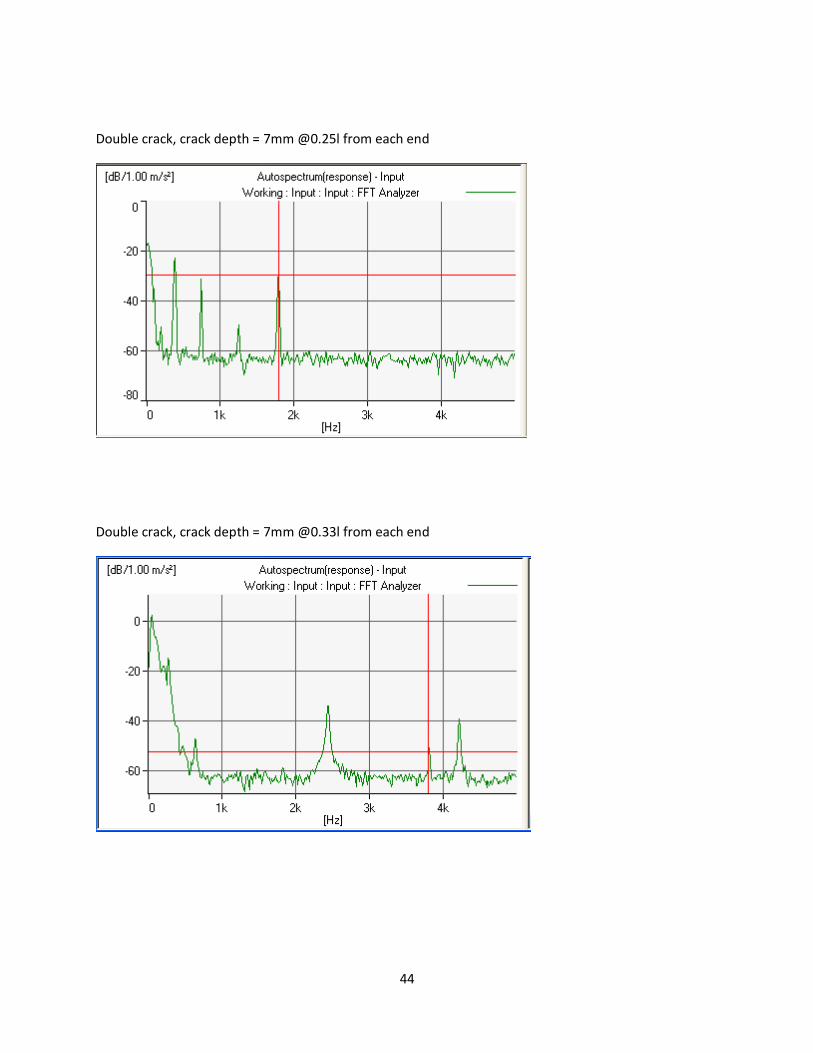
Double crack, crack depth = 7mm @0.25l from each end
Double crack, crack depth = 7mm @0.33l from each end
45
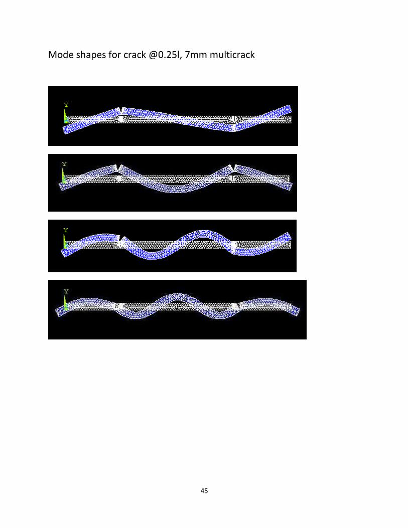
Mode shapes for crack @0.25l, 7mm multicrack
46
47
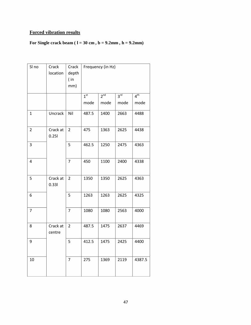
Forced vibration results
For Single crack beam ( l = 30 cm , b = 9.2mm , h = 9.2mm)
Sl no Crack
location
Crack
depth
( in
mm)
Frequency (in Hz)
1st
mode
2nd
mode
3rd
mode
4th
mode
1 Uncrack Nil 487.5 1400 2663 4488
2 Crack at
0.25l
2 475 1363 2625 4438
3 5 462.5 1250 2475 4363
4 7 450 1100 2400 4338
5 Crack at
0.33l
2 1350 1350 2625 4363
6 5 1263 1263 2625 4325
7 7 1080 1080 2563 4000
8 Crack at
centre
2 487.5 1475 2637 4469
9 5 412.5 1475 2425 4400
10 7 275 1369 2119 4387.5
48
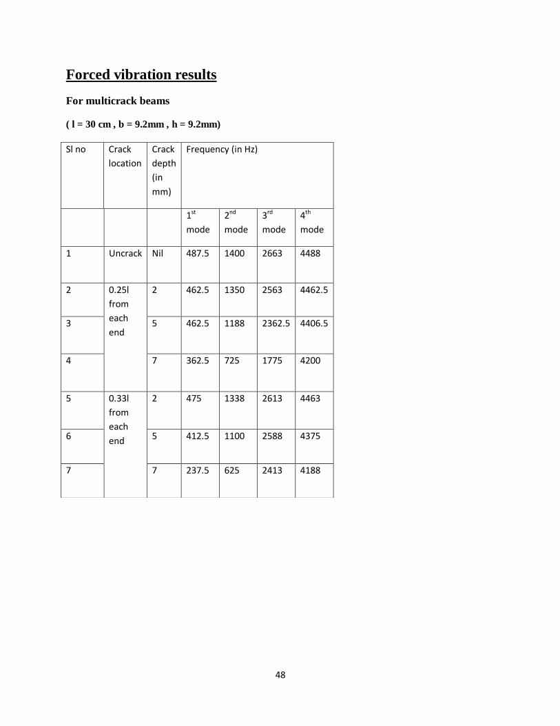
Forced vibration results
For multicrack beams
( l = 30 cm , b = 9.2mm , h = 9.2mm)
Sl no Crack
location
Crack
depth
(in
mm)
Frequency (in Hz)
1st
mode
2nd
mode
3rd
mode
4th
mode
1 Uncrack Nil 487.5 1400 2663 4488
2 0.25l
from
each
end
2 462.5 1350 2563 4462.5
3 5 462.5 1188 2362.5 4406.5
4 7 362.5 725 1775 4200
5 0.33l
from
each
end
2 475 1338 2613 4463
6 5 412.5 1100 2588 4375
7 7 237.5 625 2413 4188
49
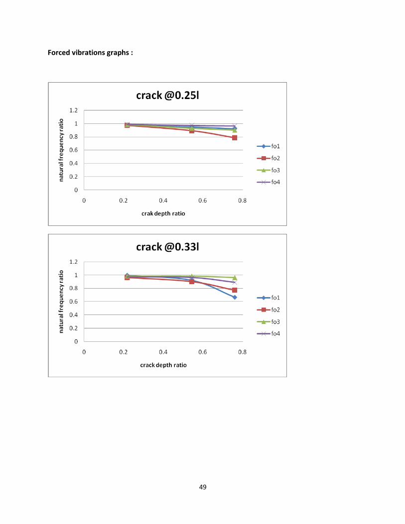
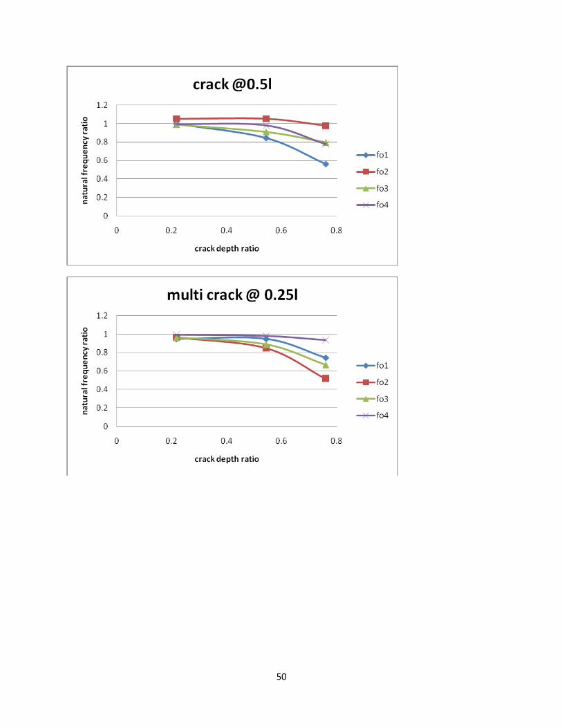
Forced vibrations graphs :
50
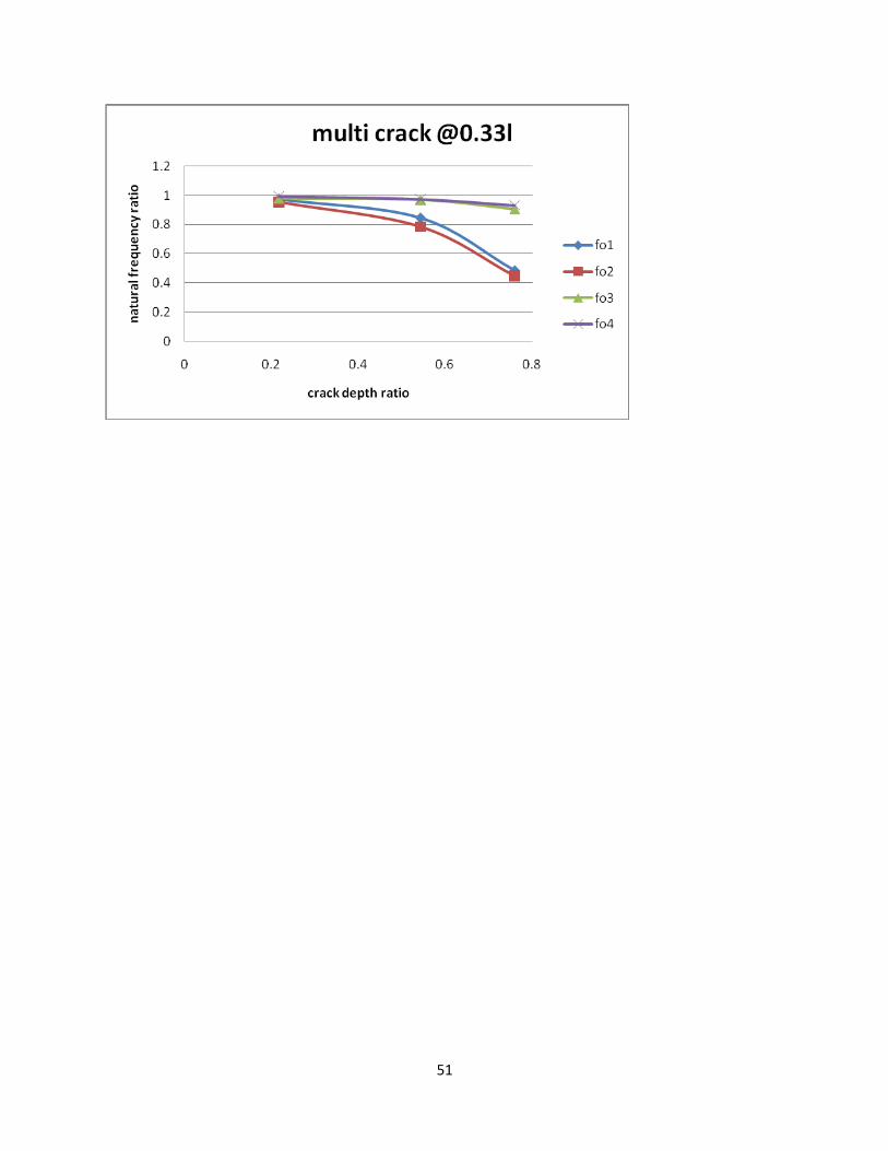
51
52
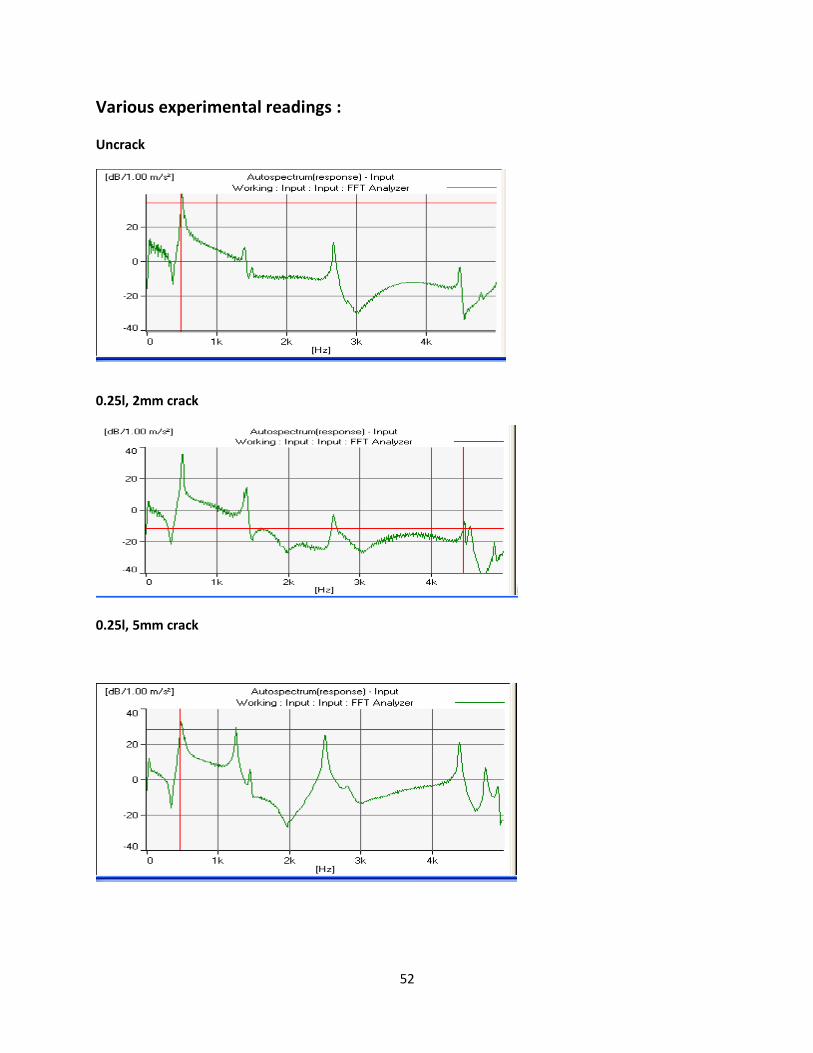
Various experimental readings :
Uncrack
0.25l, 2mm crack
0.25l, 5mm crack
53
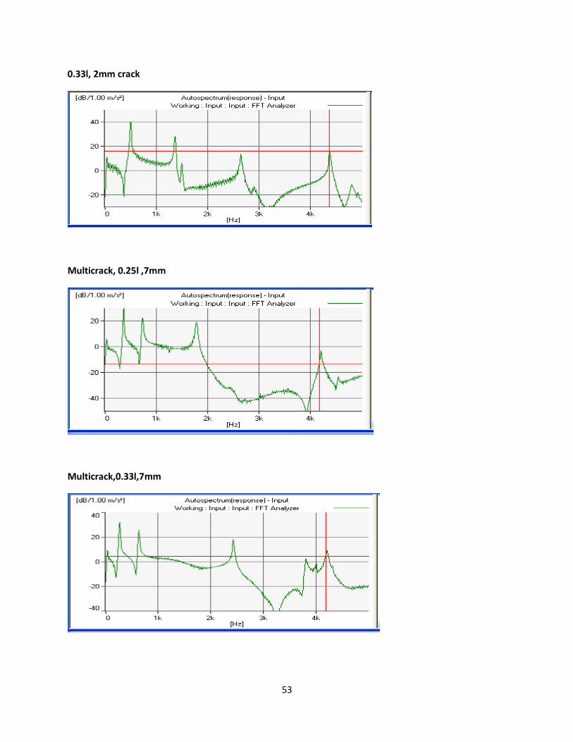
0.33l, 2mm crack
Multicrack, 0.25l ,7mm
Multicrack,0.33l,7mm
54
55
56
Conclusion: In steel beam free-free condition it was seen that the results were in good co ordinance
with theoretical values. The lowest frequency was in lowest mode. The frequency was
increasing with each subsequent mode of vibration. The percentage of error was also
decreasing as frequency is increasing.
In first mode the natural frequencies of free – free beam decreases more rapidly for
crack close to centre than the ends (i.e. the centre cracks are more affected).
In second mode the natural frequencies of free – free beam decreases more rapidly
for crack close to ends than the centre (i.e. the end cracks are more affected).
For forced vibration, it was seen that the natural frequencies were nearly similar to that
of free vibration.
57
References: [1] Radhakrishnan V.M, Response of a Cracked Cantilever Beam to Free and Forced
Vibrations , Defence Science Journal, Vol. 54, No. 1, January 2004, pp. 31-38
[2] Nahvi.H, Jabbari.M, Crack detection in beams using experimental modal data and
finite element model, International Journal of Mechanical Sciences 47 (2005) ,
pp - 1477–1497
[3] Viola.E , Nobile. L and Federici. L, Formulation of Cracked Beam Element for
Structural Analysis, Journal Of Engineering Mechanics / February 2002,pp –
220-230
[4] Ertug˘rul C¸ am*, Sadettin Orhan, Murat Lu¨y, An analysis of cracked beam
structure using impact echo method, NDT&E International 38 (2005),pp-368–373
[5] Bruel And Pulse Manual
[6] Electrodynamic Vibration Shaker System Manual