Embed Size (px)
Citation preview
324 Leaside Ave, Stoney Creek, Ontario, Canada, L8E 2N7 Toll Free: 1-800-663-9003
www.fruitlandmanufacturing.com 1
Data subject to change without notice FM-RB-2013
Banner
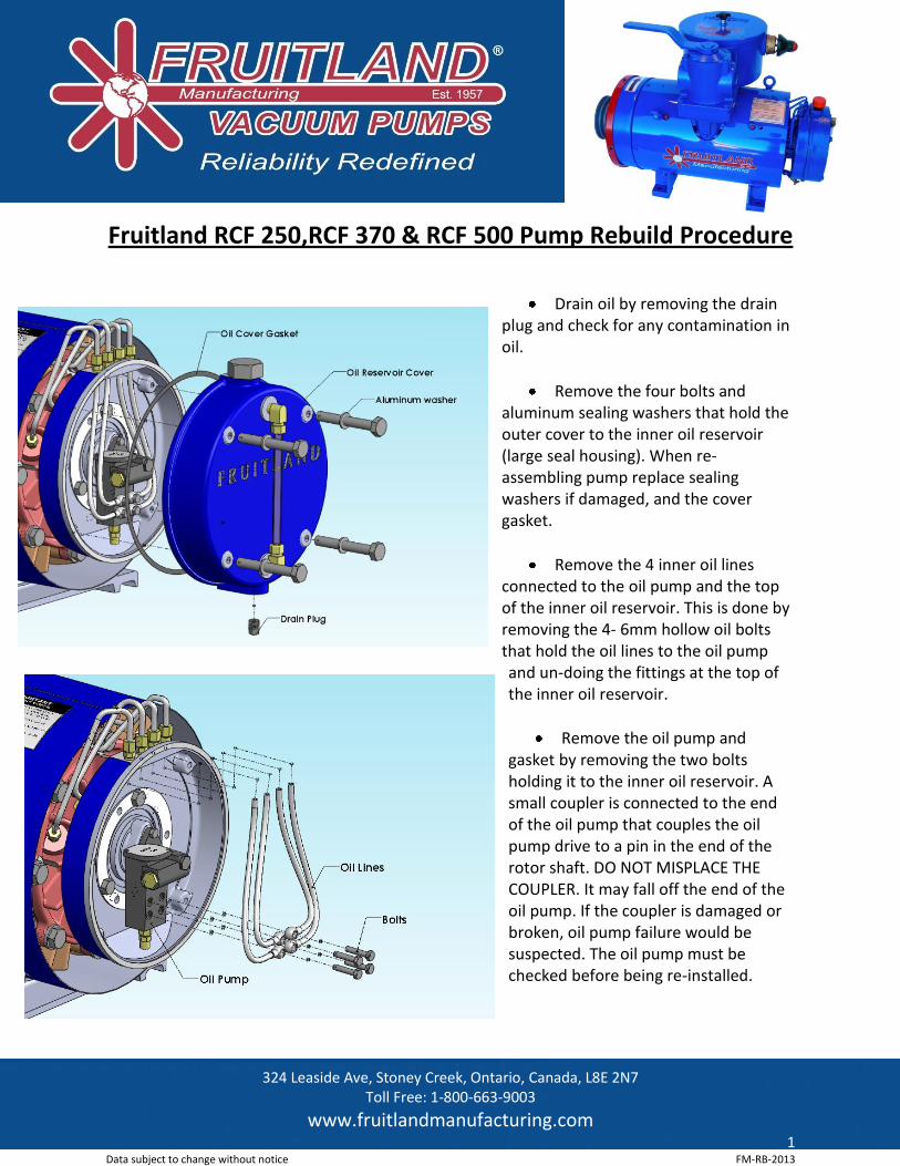
Fruitland RCF 250,RCF 370 & RCF 500 Pump Rebuild Procedure
Drain oil by removing the drain plug and check for any contamination in oil.
Remove the four bolts and aluminum sealing washers that hold the outer cover to the inner oil reservoir (large seal housing). When re-assembling pump replace sealing washers if damaged, and the cover gasket.
Remove the 4 inner oil lines connected to the oil pump and the top of the inner oil reservoir. This is done by removing the 4- 6mm hollow oil bolts that hold the oil lines to the oil pump and un-doing the fittings at the top of the inner oil reservoir.
Remove the oil pump and gasket by removing the two bolts holding it to the inner oil reservoir. A small coupler is connected to the end of the oil pump that couples the oil pump drive to a pin in the end of the rotor shaft. DO NOT MISPLACE THE COUPLER. It may fall off the end of the oil pump. If the coupler is damaged or broken, oil pump failure would be suspected. The oil pump must be checked before being re-installed.
Fruitland Manufacturing ® www.fruitlandmanufacturing.com
324 Leaside Ave, Stoney Creek, Ontario, Canada, L8E 2N7 Toll Free: 1-800-663-9003
www.fruitlandmanufacturing.com 2
Data subject to change without notice FM-RB-2013
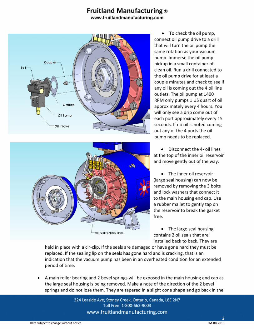
To check the oil pump, connect oil pump drive to a drill that will turn the oil pump the same rotation as your vacuum pump. Immerse the oil pump pickup in a small container of clean oil. Run a drill connected to the oil pump drive for at least a couple minutes and check to see if any oil is coming out the 4 oil line outlets. The oil pump at 1400 RPM only pumps 1 US quart of oil approximately every 4 hours. You will only see a drip come out of each port approximately every 15 seconds. If no oil is noted coming out any of the 4 ports the oil pump needs to be replaced.
Disconnect the 4- oil lines at the top of the inner oil reservoir and move gently out of the way.
The inner oil reservoir (large seal housing) can now be removed by removing the 3 bolts and lock washers that connect it to the main housing end cap. Use a rubber mallet to gently tap on the reservoir to break the gasket free.
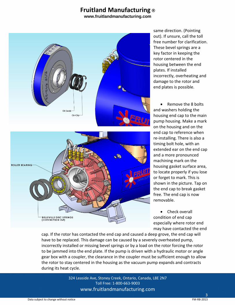
The large seal housing contains 2 oil seals that are installed back to back. They are
held in place with a cir-clip. If the seals are damaged or have gone hard they must be replaced. If the sealing lip on the seals has gone hard and is cracking, that is an indication that the vacuum pump has been in an overheated condition for an extended period of time.
A main roller bearing and 2 bevel springs will be exposed in the main housing end cap as the large seal housing is being removed. Make a note of the direction of the 2 bevel springs and do not lose them. They are tapered in a slight cone shape and go back in the
Fruitland Manufacturing ® www.fruitlandmanufacturing.com
324 Leaside Ave, Stoney Creek, Ontario, Canada, L8E 2N7 Toll Free: 1-800-663-9003
www.fruitlandmanufacturing.com 3
Data subject to change without notice FM-RB-2013
same direction. (Pointing out). If unsure, call the toll free number for clarification. These bevel springs are a key factor in keeping the rotor centered in the housing between the end plates. If installed incorrectly, overheating and damage to the rotor and end plates is possible.
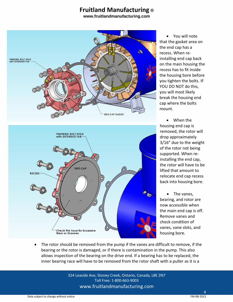
Remove the 8 bolts and washers holding the housing end cap to the main pump housing. Make a mark on the housing and on the end cap to reference when re-installing. There is also a timing bolt hole, with an extended ear on the end cap and a more pronounced machining mark on the housing gasket surface area, to locate properly if you lose or forget to mark. This is shown in the picture. Tap on the end cap to break gasket free. The end cap is now removable.
Check overall condition of end cap especially where rotor end may have contacted the end
cap. If the rotor has contacted the end cap and caused a deep grove, the end cap will have to be replaced. This damage can be caused by a severely overheated pump, incorrectly installed or missing bevel springs or by a load on the rotor forcing the rotor to be jammed into the end plate. If the pump is driven with a hydraulic motor or angle gear box with a coupler, the clearance in the coupler must be sufficient enough to allow the rotor to stay centered in the housing as the vacuum pump expands and contracts during its heat cycle.
Fruitland Manufacturing ® www.fruitlandmanufacturing.com
324 Leaside Ave, Stoney Creek, Ontario, Canada, L8E 2N7 Toll Free: 1-800-663-9003
www.fruitlandmanufacturing.com 4
Data subject to change without notice FM-RB-2013
You will note that the gasket area on the end cap has a recess. When re-installing end cap back on the main housing the recess has to fit inside the housing bore before you tighten the bolts. IF YOU DO NOT do this, you will most likely break the housing end cap where the bolts mount.
When the housing end cap is removed, the rotor will drop approximately 3/16” due to the weight of the rotor not being supported. When re-installing the end cap, the rotor will have to be lifted that amount to relocate end cap recess back into housing bore.
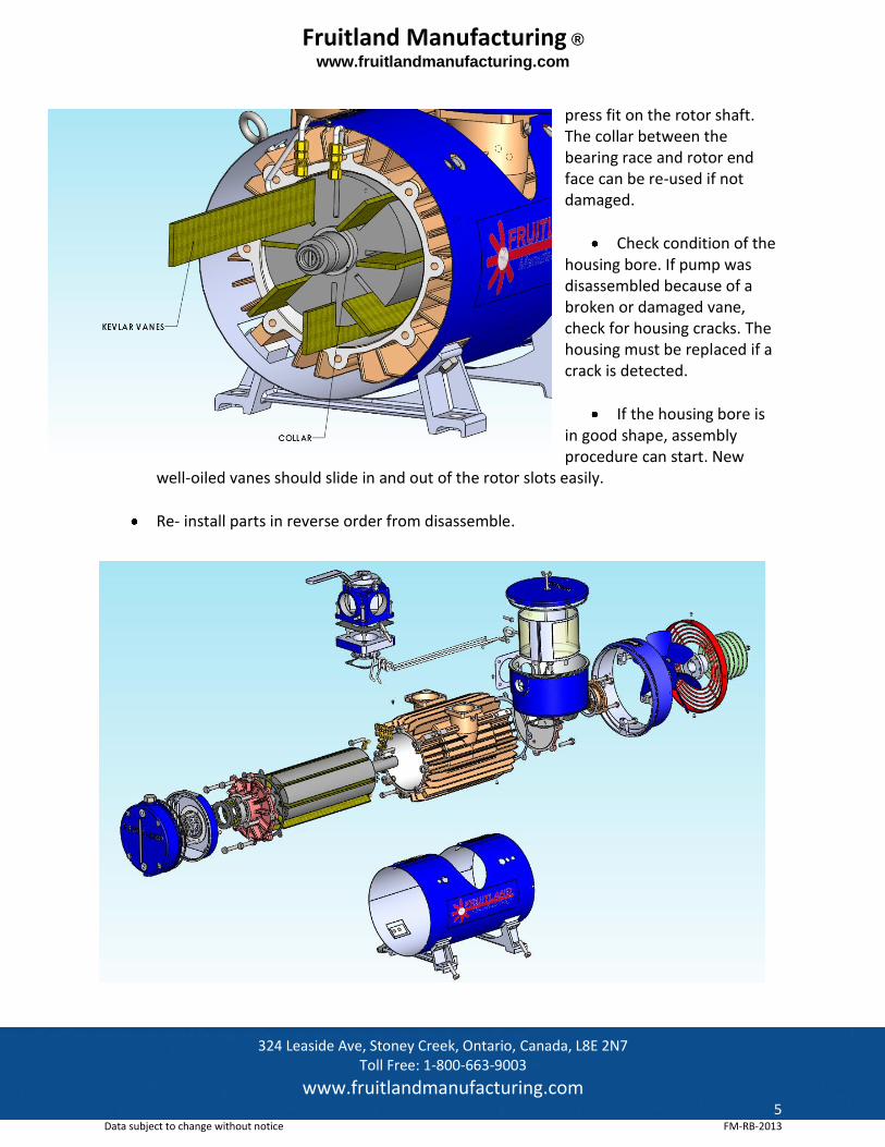
The vanes, bearing, and rotor are now accessible when the main end cap is off. Remove vanes and check condition of vanes, vane slots, and housing bore.
The rotor should be removed from the pump if the vanes are difficult to remove, if the bearing or the rotor is damaged, or if there is contamination in the pump. This also allows inspection of the bearing on the drive end. If a bearing has to be replaced, the inner bearing race will have to be removed from the rotor shaft with a puller as it is a
Fig. 7
Fruitland Manufacturing ® www.fruitlandmanufacturing.com
324 Leaside Ave, Stoney Creek, Ontario, Canada, L8E 2N7 Toll Free: 1-800-663-9003
www.fruitlandmanufacturing.com 5
Data subject to change without notice FM-RB-2013
press fit on the rotor shaft. The collar between the bearing race and rotor end face can be re-used if not damaged.
Check condition of the housing bore. If pump was disassembled because of a broken or damaged vane, check for housing cracks. The housing must be replaced if a crack is detected.
If the housing bore is in good shape, assembly procedure can start. New
well-oiled vanes should slide in and out of the rotor slots easily.
Re- install parts in reverse order from disassemble.
Reliability Redefined™
VACUUM PUMPSVACUUM PUMPSEst. 1957
FRUITLANDManufacturing
Toll Free: 1-800-663-9003 905-662-6552 www.fruitlandmanufacturing.com
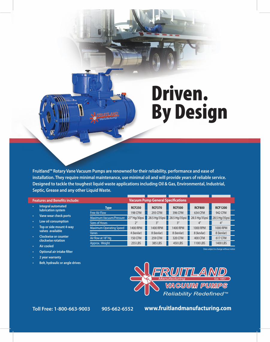
Fruitland™ Rotary Vane Vacuum Pumps are renowned for their reliability, performance and ease of installation. They require minimal maintenance, use minimal oil and will provide years of reliable service. Designed to tackle the toughest liquid waste applications including Oil & Gas, Environmental, Industrial, Septic, Grease and any other Liquid Waste.
Driven. By Design
Type RCF250 RCF370 RCF500 RCF800 RCF1200Free Air Flow 198 CFM 293 CFM 396 CFM 634 CFM 942 CFM
Maximum Vacuum/Pressure 27” Hg/30psi 28.5 Hg/35psi 28.5 Hg/35psi 28.5 Hg/35psi 28.5 Hg/35psi
Sizes of Hoses 2“ 3” 3“ 4” 4“
Maximum Operating Speed 1400 RPM 1400 RPM 1400 RPM 1000 RPM 1000 RPM
Vanes 4 (kevlar) 8 (kevlar) 8 (kevlar) 8 (kevlar) 8 (kevlar)
Air flow at 18” Hg 150 CFM 259 CFM 320 CFM 400 CFM 617 CFM
Approx. Weight 255 LBS 385 LBS 450 LBS 1100 LBS 1400 LBS
Vacuum Pump General Speci�cations
Data subject to change without notice
Features and Bene�ts include:• Integral automated lubrication system
• Vane wear check ports
• Low oil consumption
• Top or side mount 4-way valves available
• Clockwise or counter clockwise rotation
• Air cooled
• Optional air intake filter
• 2 year warranty
• Belt, hydraulic or angle drives