Embed Size (px)
Citation preview
Workbook
With CD-ROM
Festo Didactic
567283 en
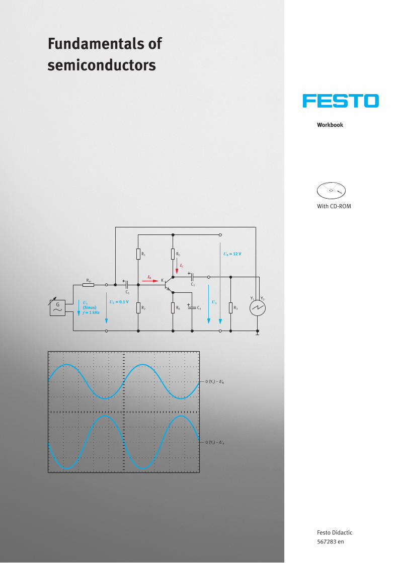
Fundamentals of semiconductors
0 (Y ) –1 UE
0 (Y ) –2 UA
Y2
KIB
IC
RC
RE C3
C1
UA
UB = 12 V
R3
Y1
R2
R1
UE = 0.1 V
Rm
G U
f
S(Sinus)
= 1 kHz
C2

Order no.: 567283
Edition: 09/2010
Author: Melanie Wäschle
Edited by: Frank Ebel
Graphics: Remo Jedelhauser, Melanie Wäschle
Layout: 02/2011, Frank Ebel
© Festo Didactic GmbH & Co. KG, 73770 Denkendorf, Germany 2011
Internet: www.festo-didactic.com
E-mail: [email protected]
The copying, distribution and utilization of this document as well as the communication of its contents to
others without expressed authorization is prohibited. Offenders will be held liable for the payment of
damages. All rights reserved, in particular the right to carry out patent, utility model or ornamental design
registration.
© Festo Didactic GmbH & Co. KG 567283 III
Contents
Intended use ____________________________________________________________________________ IV
Preface ______________________________________________________________________________ V
Introduction ____________________________________________________________________________ VII
Work and safety instructions ______________________________________________________________ VIII
Training package – Fundamentals of electrical engineering/electronics (TP 1011) ___________________ IX
Learning objectives – Fundamentals of semiconductors ___________________________________________X
Allocation of learning objectives and exercises – Fundamentals of semiconductors ____________________ XI
Equipment set __________________________________________________________________________ XII
Allocation of components and exercises – Fundamentals of semiconductors ________________________ XVI
Notes for the teacher/trainer ______________________________________________________________ XVIII
Structure of the exercises _________________________________________________________________ XIX
Component designations __________________________________________________________________ XIX
Contents of the CD-ROM __________________________________________________________________ XX
Exercises and solutions
Exercise 1: Selecting semiconductor diodes for power reduction __________________________________ 3
Exercise 2: Using Zener diodes to stabilise the output voltage of a power supply unit _______________ 21
Exercise 3: Selecting a series resistor of the correct size for an LED ______________________________ 39
Exercise 4: Amplifying the output signal of a microphone ______________________________________ 51
Exercise 5: Switching a light on and off with a field-effect transistor ______________________________ 81
Exercises and worksheets
Exercise 1: Selecting semiconductor diodes for power reduction __________________________________ 3
Exercise 2: Using Zener diodes to stabilise the output voltage of a power supply unit _______________ 21
Exercise 3: Selecting a series resistor of the correct size for an LED ______________________________ 39
Exercise 4: Amplifying the output signal of a microphone ______________________________________ 51
Exercise 5: Switching a light on and off with a field-effect transistor ______________________________ 81

IV © Festo Didactic GmbH & Co. KG 567283
Intended use
The training package “Fundamentals of electrical engineering/electronics” should only be used:
• For its intended purpose in teaching and training applications
• When its safety functions are in flawless condition
The components included in the training package are designed in accordance with the latest technology, as
well as recognised safety rules. However, life and limb of the user and third parties may be endangered, and
the components may be impaired if they are used improperly.
The learning system from Festo Didactic has been developed and produced exclusively for training and
further education in the field of automation technology. The training companies and/or trainers must ensure
that all trainees observe the safety instructions described in this workbook.
Festo Didactic hereby excludes any and all liability for damages suffered by trainees, the training company
and/or any third parties, which occur during use of the equipment sets in situations which serve any
purpose other than training and/or vocational education, unless such damages have been caused by Festo
Didactic due to malicious intent or gross negligence.
© Festo Didactic GmbH & Co. KG 567283 V
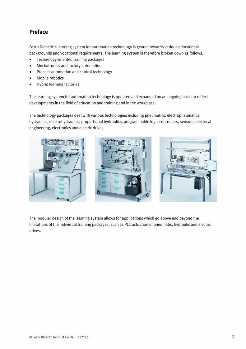
Preface
Festo Didactic’s learning system for automation technology is geared towards various educational
backgrounds and vocational requirements. The learning system is therefore broken down as follows:
• Technology-oriented training packages
• Mechatronics and factory automation
• Process automation and control technology
• Mobile robotics
• Hybrid learning factories
The learning system for automation technology is updated and expanded on an ongoing basis to reflect
developments in the field of education and training and in the workplace.
The technology packages deal with various technologies including pneumatics, electropneumatics,
hydraulics, electrohydraulics, proportional hydraulics, programmable logic controllers, sensors, electrical
engineering, electronics and electric drives.
The modular design of the learning system allows for applications which go above and beyond the
limitations of the individual training packages, such as PLC actuation of pneumatic, hydraulic and electric
drives.

VI © Festo Didactic GmbH & Co. KG 567283
All training packages feature the following elements:
• Hardware
• Media
• Seminars
Hardware The hardware in the training packages is comprised of industrial components and systems that are specially
designed for training purposes. The choice of components and their configuration in the training packages is
specifically adapted to the projects in the accompanying media.
Media The media provided for the various topics consist of a mixture of courseware and software. The courseware
includes:
• Technical literature and textbooks (standard works for teaching basic knowledge)
• Workbooks (practical exercises with supplementary instructions and sample solutions)
• Glossaries, manuals and technical books (providing more in-depth information on the various topics)
• Transparencies and videos (for easy-to-follow, dynamic instruction)
• Posters (to present information in a clear-cut way)
Within the software, the following programs are available:
• Digital training programs (learning content specifically designed for virtual training)
• Simulation software
• Visualisation software
• Software for measured data acquisition
• Project engineering and design engineering software
• Programming software for programmable logic controllers
The teaching and learning media are available in several languages. They are intended for use in classroom
instruction, but are also suitable for self-study.
Seminars A wide range of seminars covering the contents of the training packages round off the system for training
and vocational education.
If you have any suggestions or feedback about this manual,
please send us an e-mail at: [email protected]
The authors and Festo Didactic look forward to your comments.
© Festo Didactic GmbH & Co. KG 567283 VII
Introduction
This workbook is part of the learning system for automation technology from Festo Didactic GmbH & Co. KG.
The system provides a solid basis for practice-oriented training and further education. The training package
“Fundamentals of electrical engineering/electronics” (TP 1011) covers the following topics:
• Fundamentals of direct current technology
• Fundamentals of alternating current technology
• Fundamentals of semiconductors
• Basic electronic circuits
The workbook “Fundamentals of semiconductors” deals with semiconductor components. It begins by
looking at different diodes such as semiconductor diodes, Zener diodes and light-emitting diodes and
working through the basic concepts relating to them. Topics such as P-N junctions, reverse voltage and
forward current are examined theoretically and, where possible, also demonstrated in terms of
measurement technology. Finally, the topic of transistors is explained in terms of bipolar and unipolar
transistors.
A laboratory workstation, equipped with a protected power supply, two digital multimeters, a storage
oscilloscope and safety laboratory cables, is needed to build and evaluate the circuits.
All circuits for the five exercises for “Fundamentals of semiconductors” can be built using the TP 1011
equipment set. The basic theoretical principles needed to understand these exercises are included in these
textbooks:
• Skills for the Electrical Industry, order no. 567297
• Electrical engineering, order no. 567298.
Technical data for the various components (diodes, transistors, measuring devices etc.) is also available.

VIII © Festo Didactic GmbH & Co. KG 567283
Work and safety instructions
General • Trainees should only work with the circuits under the supervision of a trainer.
• Observe the specifications included in the data sheets for the individual components and in particular
all safety instructions.
• Faults which may impair safety must not be generated in the training environment and must be
eliminated immediately.
Electrical components • Risk of fatal injury from interrupted protective earth conductor!
– The protective earth conductor (yellow/green) must never be interrupted, either inside or outside a
device.
– The insulation of the protective earth conductor must never be damaged or removed.
• The German trade association regulations BGV A3, “Electrical systems and equipment”, should be
observed in industrial facilities.
• In schools and training centres, the operation of power supply units must be responsibly monitored by
trained staff.
• Caution! The capacitors in the device may still carry a charge even when the device has been disconnected from
all power sources.
• When replacing fuses: use only specified fuses with the correct current rating.
• Never switch on the power supply unit immediately after it has been moved from a cold room to a warm
room. The condensate that forms can, under unfavourable conditions, damage the device. Leave the
device switched off until it has reached room temperature.
• Use only extra-low voltage (max. 25 V DC) as the operating voltage for the circuits in the various
exercises.
• The power must be disconnected before establishing electrical connections.
• The power must be disconnected before breaking electrical connections.
• Use only connecting cables with safety plugs for electrical connections.
• Always pull the safety plug when disconnecting connecting cables – never pull the cable.
© Festo Didactic GmbH & Co. KG 567283 IX
Training package – Fundamentals of electrical engineering/electronics (TP 1011)
The training package TP 1011 consists of a multitude of training materials. This part of the training package
TP 1011 deals with the basic principles of semiconductors. Individual components included in the training
package TP 1011 can also be included in other packages.
Important components of TP 1011 • Permanent workstation with EduTrainer® universal patch panel
• Component set for electrical engineering/electronics with jumper plugs and safety laboratory cables
• Basic power supply unit EduTrainer®
• Set of laboratory equipment
Media The courseware for the training package TP 1011 consists of technical books, books of tables for reference,
and workbooks. The textbooks explain the basics of semiconductor technology in a clearly structured and
easy-to-follow way. The workbooks contain the worksheets for every exercise, the solutions for each
individual worksheet and a CD-ROM. A set of ready-to-use exercise sheets and worksheets for every exercise
is included with every workbook.
Technical data for the hardware components is supplied with the training package and on the CD-ROM.
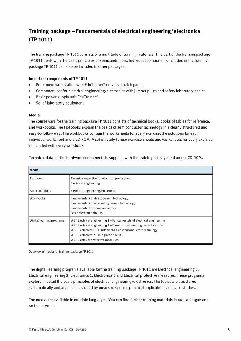
Media
Textbooks Technical expertise for electrical professions
Electrical engineering
Books of tables Electrical engineering/electronics
Workbooks Fundamentals of direct current technology
Fundamentals of alternating current technology
Fundamentals of semiconductors
Basic electronic circuits
Digital learning programs WBT Electrical engineering 1 – Fundamentals of electrical engineering
WBT Electrical engineering 2 – Direct and alternating current circuits
WBT Electronics 1 – Fundamentals of semiconductor technology
WBT Electronics 2 – Integrated circuits
WBT Electrical protective measures
Overview of media for training package TP 1011
The digital learning programs available for the training package TP 1011 are Electrical engineering 1,
Electrical engineering 2, Electronics 1, Electronics 2 and Electrical protective measures. These programs
explore in detail the basic principles of electrical engineering/electronics. The topics are structured
systematically and are also illustrated by means of specific practical applications and case studies.
The media are available in multiple languages. You can find further training materials in our catalogue and
on the internet.

X © Festo Didactic GmbH & Co. KG 567283
Learning objectives – Fundamentals of semiconductors
• You will become familiar with the structure and workings of semiconductor diodes.
• You will become familiar with the characteristic curve of a silicon diode.
• You will become familiar with the most important characteristics of semiconductor diodes.
• You will be able to locate the diode's operating point on a graph.
• You will become familiar with the workings of a Zener diode.
• You will become familiar with the relationships between voltages and currents in a stabiliser circuit with
a Zener diode.
• You will be able to design a stabiliser circuit for the correct capacity.
• You will become familiar with the workings of light-emitting diodes.
• You will become familiar with the relationship between the different colours of LEDs and the forward
voltage.
• You will be able to select a series resistor of the correct size for an LED.
• You will become familiar with the structure and workings of the transistor.
• You will become familiar with the input characteristic, the transfer characteristic and the output
characteristic.
• You will be able to adjust the operating point of a transistor.
• You will be able to determine the AC voltage gain and the AC current gain for an amplifier stage.
• You will become familiar with the different types of field-effect transistors and their crucial differences.
• You will become familiar with important parameters of junction field-effect transistors.
• You will become familiar with the input and output characteristics of a junction field-effect transistor.
• You will be able to read off the FET's cut-off voltage from the characteristic curves.
• You will be able to build a circuit to switch a light on and off with an FET.
© Festo Didactic GmbH & Co. KG 567283 XI
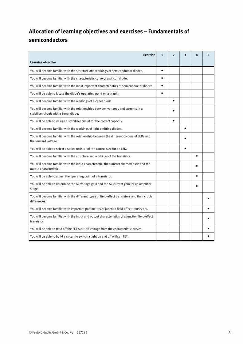
Allocation of learning objectives and exercises – Fundamentals of semiconductors
Exercise 1 2 3 4 5
Learning objective
You will become familiar with the structure and workings of semiconductor diodes. •
You will become familiar with the characteristic curve of a silicon diode. •
You will become familiar with the most important characteristics of semiconductor diodes. •
You will be able to locate the diode's operating point on a graph. •
You will become familiar with the workings of a Zener diode. •
You will become familiar with the relationships between voltages and currents in a
stabiliser circuit with a Zener diode. •
You will be able to design a stabiliser circuit for the correct capacity. •
You will become familiar with the workings of light-emitting diodes. •
You will become familiar with the relationship between the different colours of LEDs and
the forward voltage. •
You will be able to select a series resistor of the correct size for an LED. •
You will become familiar with the structure and workings of the transistor. •
You will become familiar with the input characteristic, the transfer characteristic and the
output characteristic. •
You will be able to adjust the operating point of a transistor. •
You will be able to determine the AC voltage gain and the AC current gain for an amplifier
stage. •
You will become familiar with the different types of field-effect transistors and their crucial
differences. •
You will become familiar with important parameters of junction field-effect transistors. •
You will become familiar with the input and output characteristics of a junction field-effect
transistor. •
You will be able to read off the FET's cut-off voltage from the characteristic curves. •
You will be able to build a circuit to switch a light on and off with an FET. •

XII © Festo Didactic GmbH & Co. KG 567283
Equipment set
The “Fundamentals of semiconductors” workbook covers the structure and function of the circuit
components and the behaviour of the components in basic circuits and simple application circuits.
The “Fundamentals of electrical engineering/electronics” (TP 1011) contains all the components required to
achieve the specified learning objectives. Two digital multimeters, a digital storage oscilloscope and safety
laboratory cables are also needed for building and evaluating functioning circuits.
Equipment set – Fundamentals of electrical engineering/electronics, order no. 571780
Component Order no. Quantity
Basic power supply unit EduTrainer® 567321 1
Universal patch panel EduTrainer® 567322 1
Component set for electrical engineering/electronics 567306 1
Set of jumper plugs, 19 mm, grey-black 571809 1
Overview of the component set for electrical engineering/electronics, order no. 567306
Component Quantity
Resistor, 10 Ω/2 W 1
Resistor, 22 Ω/2 W 2
Resistor, 33 Ω/2 W 1
Resistor, 100 Ω/2 W 2
Resistor, 220 Ω/2 W 1
Resistor, 330 Ω/2 W 1
Resistor, 470 Ω/2 W 2
Resistor, 680 Ω/2 W 1
Resistor, 1 kΩ/2 W 3
Resistor, 2.2 kΩ/2 W 2
Resistor, 4.7 kΩ/2 W 2
Resistor, 10 kΩ/2 W 3
Resistor, 22 kΩ/2 W 3
Resistor, 47 kΩ/2 W 2
Resistor, 100 kΩ/2 W 2
Resistor, 1 MΩ/2 W 1

© Festo Didactic GmbH & Co. KG 567283 XIII
Component Quantity
Potentiometer, 1 kΩ/0.5 W 1
Potentiometer, 10 kΩ/0.5 W 1
Thermistor (NTC), 4.7 kΩ/0.45 W 1
Light-dependent resistor (LDR), 100 V/0.2 W 1
Voltage-dependent resistor (VDR), 14 V/0.05 W 1
Capacitor, 100 pF/100 V 1
Capacitor, 10 nF/100 V 2
Capacitor, 47 nF/100 V 1
Capacitor, 0.1 μF/100 V 2
Capacitor, 0.22 μF/100 V 1
Capacitor, 0.47 μF/100 V 2
Capacitor, 1.0 μF/100 V 2
Capacitor, 10 μF/250 V, polarised 2
Capacitor, 100 μF/63 V, polarised 1
Capacitor, 470 μF/50 V, polarised 1
Coil, 100 mH/50 mA 1
Diode, AA118 1
Diode, 1N4007 6
Zener diode, ZPD 3.3 1
Zener diode, ZPD 10 1
Diac, 33 V/1 mA 1
NPN transistor, BC140, 40 V/1 A 2
NPN transistor, BC547, 50 V/100 mA 1
PNP transistor, BC160, 40 V/1 A 1
P-channel JFET transistor, 2N3820, 20 V/10 mA 1
N-channel JFET transistor, 2N3819, 25 V/50 mA 1
UNIJUNCTION transistor, 2N2647, 35 V/50 mA 1
P-channel MOSFET transistor, BS250, 60 V/180 mA 1
Thyristor, TIC 106, 400 V/5 A 1
Triac, TIC206, 400 V/4 A 1
Transformer coil, N = 200 1
Transformer coil, N = 600 2
Transformer iron core with holder 1
Indicator light, 12 V/62 mA 1
Light-emitting diode (LED), 20 mA, blue 1
Light-emitting diode (LED), 20 mA, red or green 1
Changeover switch 1

XIV © Festo Didactic GmbH & Co. KG 567283
Graphical symbols for the equipment set
Component Graphical symbol Component Graphical symbol
Resistor Zener diode
Potentiometer Diac
Thermistor (NTC) NPN transistor
Light-dependent resistor (LDR) PNP transistor
Voltage-dependent resistor
(VDR)
U
P-channel JFET transistor
Capacitor N-channel JFET transistor
Capacitor, polarised UNIJUNCTION transistor
Coil P-channel MOSFET transistor
Diode Thyristor
© Festo Didactic GmbH & Co. KG 567283 XV
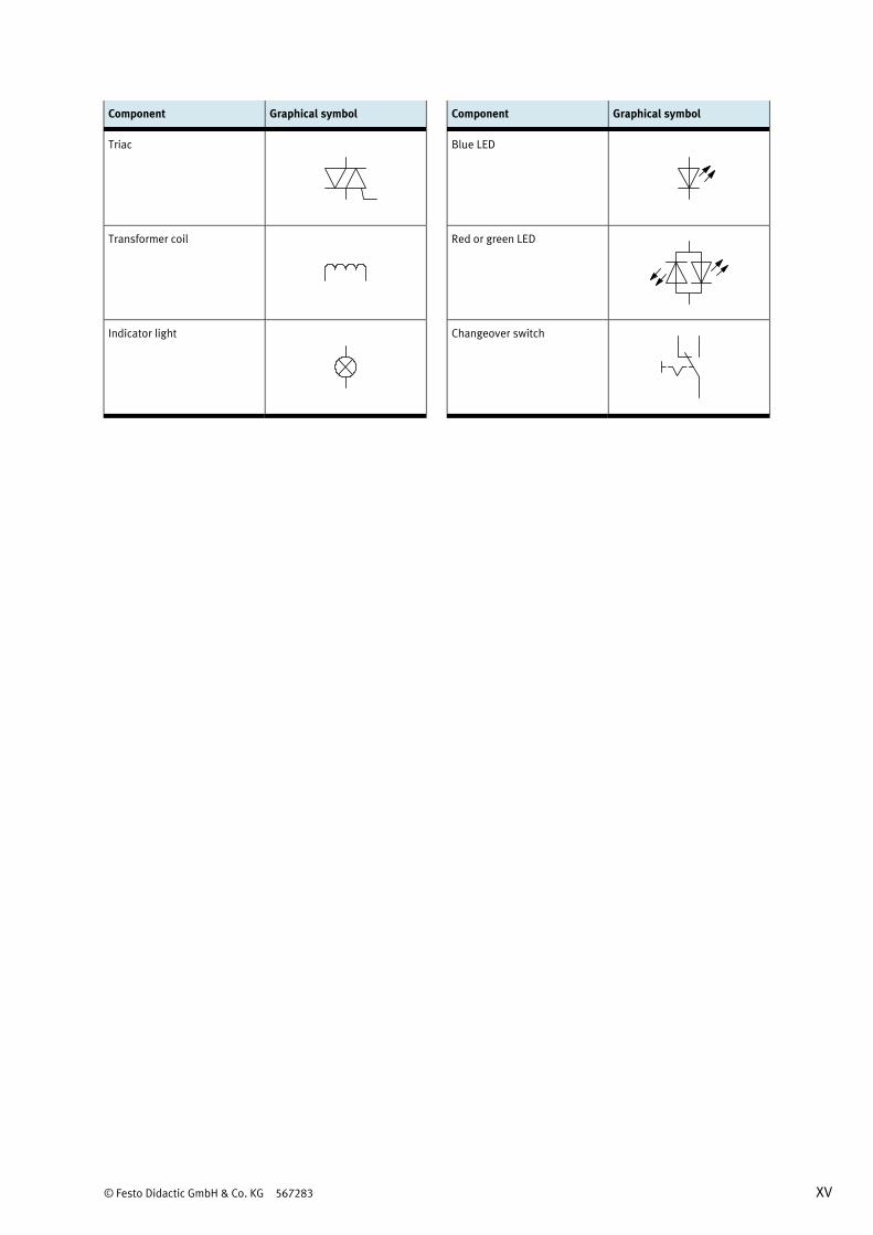
Component Graphical symbol Component Graphical symbol
Triac Blue LED
Transformer coil Red or green LED
Indicator light Changeover switch
XVI © Festo Didactic GmbH & Co. KG 567283
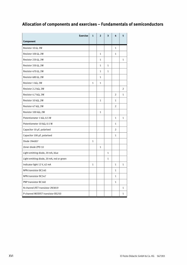
Allocation of components and exercises – Fundamentals of semiconductors
Exercise 1 2 3 4 5
Component
Resistor 10 Ω, 2W 1
Resistor 100 Ω, 2W 1 1
Resistor 220 Ω, 2W 1 1
Resistor 330 Ω, 2W 1 1
Resistor 470 Ω, 2W 1 1
Resistor 680 Ω, 2W 1
Resistor 1 kΩ, 2W 1 1
Resistor 2.2 kΩ, 2W 2
Resistor 4.7 kΩ, 2W 2 1
Resistor 10 kΩ, 2W 1 1
Resistor 47 kΩ, 2W 2
Resistor 100 kΩ, 2W 1
Potentiometer 1 kΩ, 0.5 W 1 1
Potentiometer 10 kΩ, 0.5 W 1
Capacitor 10 μF, polarised 2
Capacitor 100 μF, polarised 1
Diode 1N4007 1
Zener diode ZPD 10 1
Light-emitting diode, 20 mA, blue 1
Light-emitting diode, 20 mA, red or green 1
Indicator light 12 V, 62 mA 1 1 1
NPN transistor BC140 1
NPN transistor BC547 1
PNP transistor BC160 1
N-channel JFET transistor 2N3819 1
P-channel MOSFET transistor BS250 1

© Festo Didactic GmbH & Co. KG 567283 XVII
Exercise 1 2 3 4 5
Component
Voltmeter 1 1 1 1 2
Ammeter 1 1 1 2 2
Oscilloscope 1
Basic power supply unit 1 1 1 1 1

XVIII © Festo Didactic GmbH & Co. KG 567283
Notes for the teacher/trainer
Learning objectives The general learning objective of this workbook is the analysis and understanding of simple basic circuits
using semiconductor components. It does this through a combination of theoretical questions and practical
exercises during which the students are required to build circuits and measure electrical variables. This
direct interplay of theory and practice ensures fast progress and long-lasting learning. The more specific
learning objectives are listed in detail in the matrix. Concrete, individual learning objectives are assigned to
each exercise.
Required time The time required for working through the exercises depends on the student’s previous knowledge of the
subject matter. About 1 to 1.5 hours could be scheduled for each exercise.
Components of the equipment set The workbook and the equipment set are designed to be used together. All five exercises can be completed
using components from one equipment set TP 1011.
Standards The following standards are applied in this workbook:
EN 60617-2 to EN 60617-8 Graphical symbols for circuit diagrams
EN 81346-2 Industrial systems, installations and equipment and industrial products;
structuring principles and reference designations
DIN VDE 0100-100
(IEC 60364-1)
Low-voltage electrical installations – Fundamental principles, assessment
of general characteristics, definitions
DIN VDE 0100-410
(IEC 60346-4-41)
Low-voltage electrical installations – Protective measures – Protection
against electric shock
Classifications in the workbook Solutions and supplements in graphics or diagrams are in red.
Exception: information and evaluations relating to current are always in red; information and evaluations
relating to voltage are always in blue.
Classifications in the worksheets Texts which require completion are identified with a grid or by grey cells in tables.
Graphics and diagrams which require completion include a grid.

© Festo Didactic GmbH & Co. KG 567283 XIX
Solutions The solutions given in this workbook are the results of test measurements. The results of your
measurements may vary from this data.
Learning topics The training topic “Fundamentals of semiconductors” is part of the learning topics in technical colleges for
electronic engineering.
Structure of the exercises
All five exercises have the same structure and are broken down into:
• Title
• Learning objectives
• Problem description
• Circuit or positional sketch
• Project assignment
• Work aids
• Worksheets
The workbook contains the solutions for every exercise.
Component designations
The components in the circuit diagrams are identified in accordance with DIN EN 81346-2. Letters are
assigned as appropriate to each component. Multiple components of the same type within a single circuit
are numbered.
Resistors: R, R1, R2, ...
Capacitors: C, C1, C2, …
Indicator devices: P, P1, P2, ...
Note
If resistors and capacitors are interpreted as physical variables, the letter indentifying them is in
italics (symbols). If digits are required for numbering, they are treated as indices and appear as
subscript.

XX © Festo Didactic GmbH & Co. KG 567283
Contents of the CD-ROM
The workbook is saved as a PDF file on the accompanying CD-ROM. The CD-ROM also provides you with
supplementary media.
The CD-ROM contains the following folders:
• Operating instructions
• Illustrations
• Product information
Operating instructions Operating instructions are provided for various components included in the training package. These
instructions are helpful when using and commissioning the components.
Illustrations Photos and graphics showing components and industrial applications are provided. These can be used to
illustrate individual tasks or to supplement project presentations.
Product information Contains product information from the manufacturers of selected components. The representations and
descriptions of the components in this format are intended to show how they would appear in an industrial
catalogue. Additional information regarding the components is also included.

© Festo Didactic GmbH & Co. KG 567283 1
Contents
Exercises and solutions
Exercise 1: Selecting semiconductor diodes for power reduction __________________________________ 3
Exercise 2: Using Zener diodes to stabilise the output voltage of a power supply unit _______________ 21
Exercise 3: Selecting a series resistor of the correct size for an LED ______________________________ 39
Exercise 4: Amplifying the output signal of a microphone ______________________________________ 51
Exercise 5: Switching a light on and off with a field-effect transistor ______________________________ 81

2 © Festo Didactic GmbH & Co. KG 567283
© Festo Didactic GmbH & Co. KG 567283 3
Exercise 1 Selecting semiconductor diodes for power reduction
Learning objectives After completing this exercise:
• You will be familiar with the structure and workings of semiconductor diodes.
• You will be familiar with the characteristic curve of a silicon diode.
• You will be familiar with the most important characteristics of semiconductor diodes.
• You will be able to locate the diode's operating point on a graph.
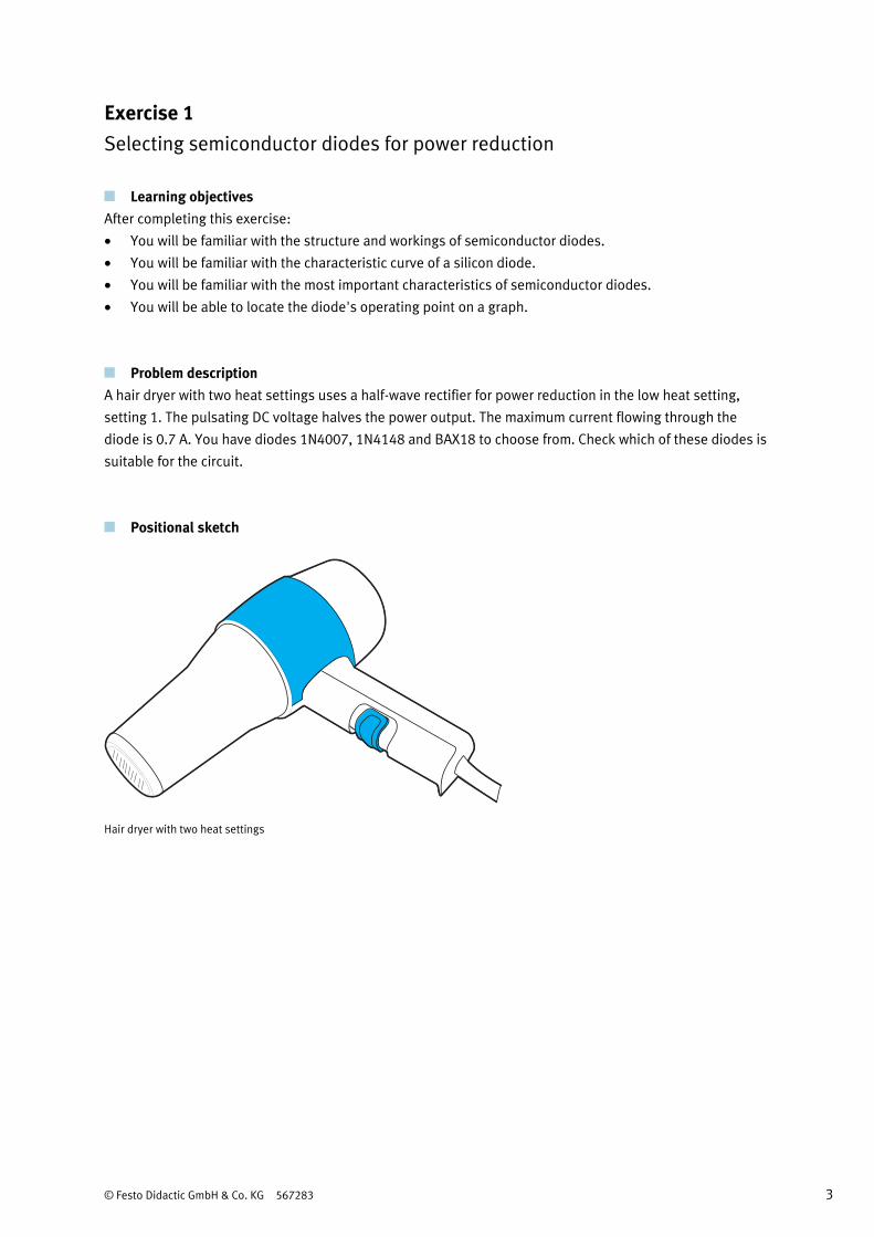
Problem description A hair dryer with two heat settings uses a half-wave rectifier for power reduction in the low heat setting,
setting 1. The pulsating DC voltage halves the power output. The maximum current flowing through the
diode is 0.7 A. You have diodes 1N4007, 1N4148 and BAX18 to choose from. Check which of these diodes is
suitable for the circuit.
Positional sketch
Hair dryer with two heat settings
Exercise 1 – Selecting semiconductor diodes for power reduction
4 © Festo Didactic GmbH & Co. KG 567283
Project assignments 1. Familiarise yourself with the structure of semiconductor diodes.
2. Investigate the workings of a semiconductor diode.
3. Record the characteristic curve of a semiconductor diode.
4. Locate the operating point of a semiconductor diode.
5. Explain the characteristics and ratings of semiconductor diodes.
6. Select a diode for the hair dryer and explain your choice.
Work aids • Data sheets
• Textbooks
• Books of tables
• WBT Electronics 1

Exercise 1: Selecting semiconductor diodes for power reduction
© Festo Didactic GmbH & Co. KG 567283 5
1. Structure of semiconductor diodes
Information
Diodes are semiconductors. They consist of a P-layer and an N-layer. When the differently doped
semiconductors are brought together, the P-N junction is created.
P N
a) Complete the following:
The terminal on the P-layer is called the anode.
The terminal on the N-layer is called the cathode.
b) Name two semiconductor materials used as diodes.
Silicon is the main semiconductor material used. Germanium is still used sometimes.
c) Draw the circuit symbol for a semiconductor diode and label both terminals.
1 2
1 : Anode 2 : Cathode
d) Compare the circuit symbol with the diode in the illustration and identify the terminals. Give a reason for
your answer.
1 2
1 : Anode 2 : Cathode
Reason
The ring is used to mark the cathode.
Exercise 1 – Selecting semiconductor diodes for power reduction
6 © Festo Didactic GmbH & Co. KG 567283
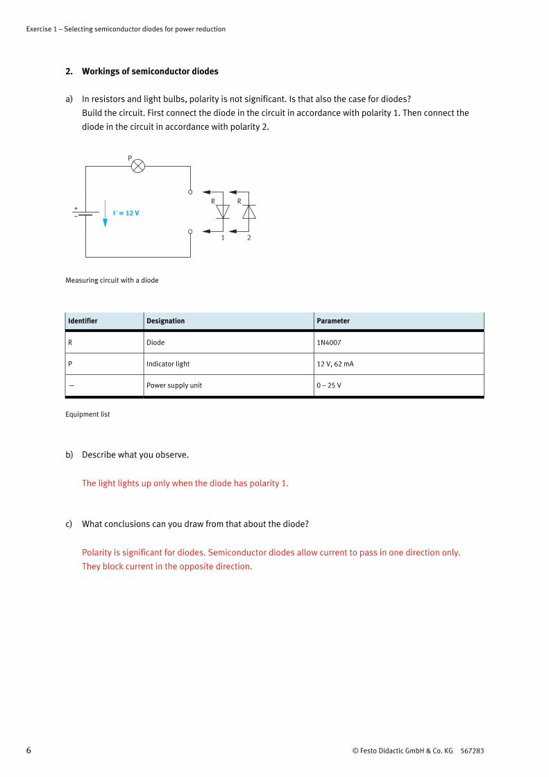
2. Workings of semiconductor diodes
a) In resistors and light bulbs, polarity is not significant. Is that also the case for diodes?
Build the circuit. First connect the diode in the circuit in accordance with polarity 1. Then connect the
diode in the circuit in accordance with polarity 2.
V = 12 V
P
R R
1 2
+
Measuring circuit with a diode
Identifier Designation Parameter
R Diode 1N4007
P Indicator light 12 V, 62 mA
— Power supply unit 0 – 25 V
Equipment list
b) Describe what you observe.
The light lights up only when the diode has polarity 1.
c) What conclusions can you draw from that about the diode?
Polarity is significant for diodes. Semiconductor diodes allow current to pass in one direction only.
They block current in the opposite direction.
Exercise 1: Selecting semiconductor diodes for power reduction
© Festo Didactic GmbH & Co. KG 567283 7
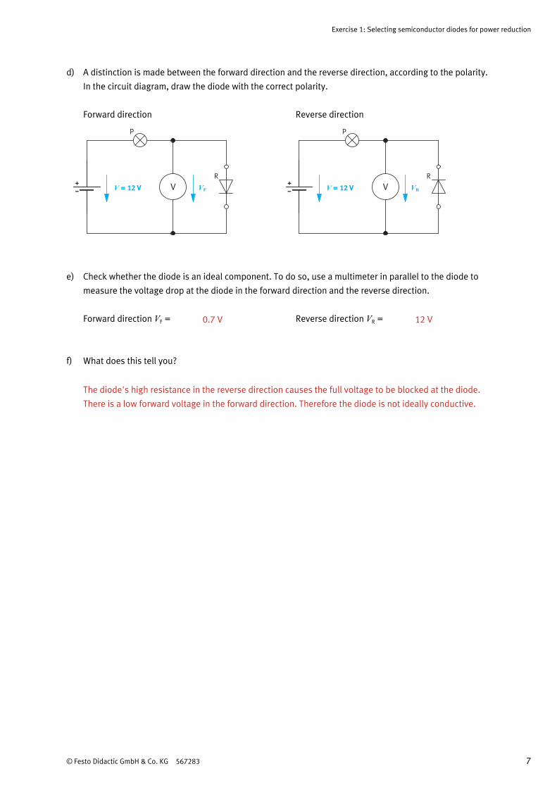
d) A distinction is made between the forward direction and the reverse direction, according to the polarity.
In the circuit diagram, draw the diode with the correct polarity.
Forward direction Reverse direction
V = 12 V+
P
R+
V VF
V = 12 V+
P
R+
V VR
e) Check whether the diode is an ideal component. To do so, use a multimeter in parallel to the diode to
measure the voltage drop at the diode in the forward direction and the reverse direction.
Forward direction VF = 0.7 V Reverse direction VR = 12 V
f) What does this tell you?
The diode's high resistance in the reverse direction causes the full voltage to be blocked at the diode.
There is a low forward voltage in the forward direction. Therefore the diode is not ideally conductive.

Exercise 1 – Selecting semiconductor diodes for power reduction
8 © Festo Didactic GmbH & Co. KG 567283
3. Recording the characteristic curve of a semiconductor diode
Information
The current-voltage characteristic curve describes the electrical behaviour of a semiconductor
diode. It displays the current flowing through the diode as a function of the voltage applied.
V = 0 – 25 V+
R+
V VF
AIF
RV
Forward direction (circuit a)
+V = 0 – 25 V
R+
V VR
AIR
RV
Reverse direction (circuit b)
Measuring circuits for recording the characteristic curve
Exercise 1: Selecting semiconductor diodes for power reduction
© Festo Didactic GmbH & Co. KG 567283 9
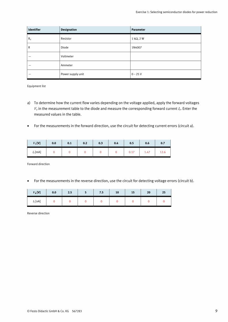
Identifier Designation Parameter
RV Resistor 1 kΩ, 2 W
R Diode 1N4007
— Voltmeter
— Ammeter
— Power supply unit 0 – 25 V
Equipment list
a) To determine how the current flow varies depending on the voltage applied, apply the forward voltages
VF in the measurement table to the diode and measure the corresponding forward current IF. Enter the
measured values in the table.
• For the measurements in the forward direction, use the circuit for detecting current errors (circuit a).
VF [V] 0.0 0.1 0.2 0.3 0.4 0.5 0.6 0.7
IF [mA] 0 0 0 0 0 0.17 1.47 12.6
Forward direction
• For the measurements in the reverse direction, use the circuit for detecting voltage errors (circuit b).
VR [V] 0.0 2.5 5 7.5 10 15 20 25
IF [nA] 0 0 0 0 0 0 0 0
Reverse direction
Exercise 1 – Selecting semiconductor diodes for power reduction
10 © Festo Didactic GmbH & Co. KG 567283
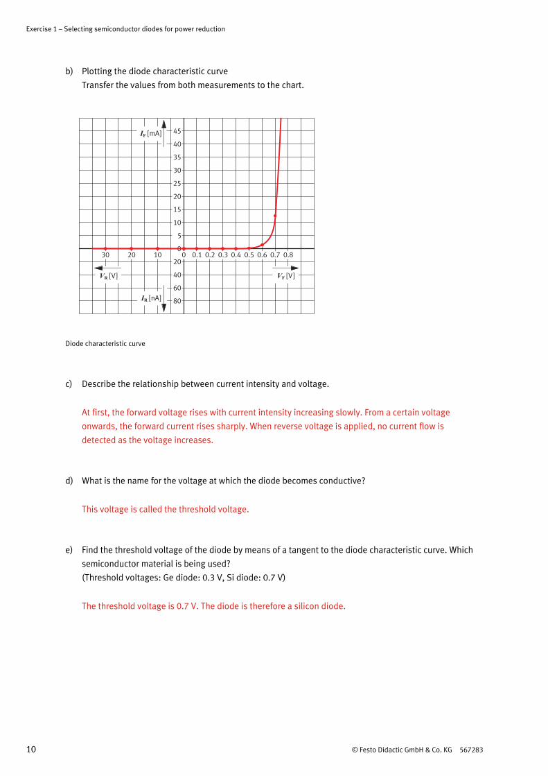
b) Plotting the diode characteristic curve
Transfer the values from both measurements to the chart.
0
20
5
10
15
20
25
30
35
40
45
40
60
80
IF [mA]
IR [nA]
VF [V]VR [V]
0102030 0.1 0.2 0.3 0.4 0.5 0.6 0.7 0.8
Diode characteristic curve
c) Describe the relationship between current intensity and voltage.
At first, the forward voltage rises with current intensity increasing slowly. From a certain voltage
onwards, the forward current rises sharply. When reverse voltage is applied, no current flow is
detected as the voltage increases.
d) What is the name for the voltage at which the diode becomes conductive?
This voltage is called the threshold voltage.
e) Find the threshold voltage of the diode by means of a tangent to the diode characteristic curve. Which
semiconductor material is being used?
(Threshold voltages: Ge diode: 0.3 V, Si diode: 0.7 V)
The threshold voltage is 0.7 V. The diode is therefore a silicon diode.
Exercise 1: Selecting semiconductor diodes for power reduction
© Festo Didactic GmbH & Co. KG 567283 11
4. Determining the operating point
Information
The operating point of a diode is usually found using a graph.
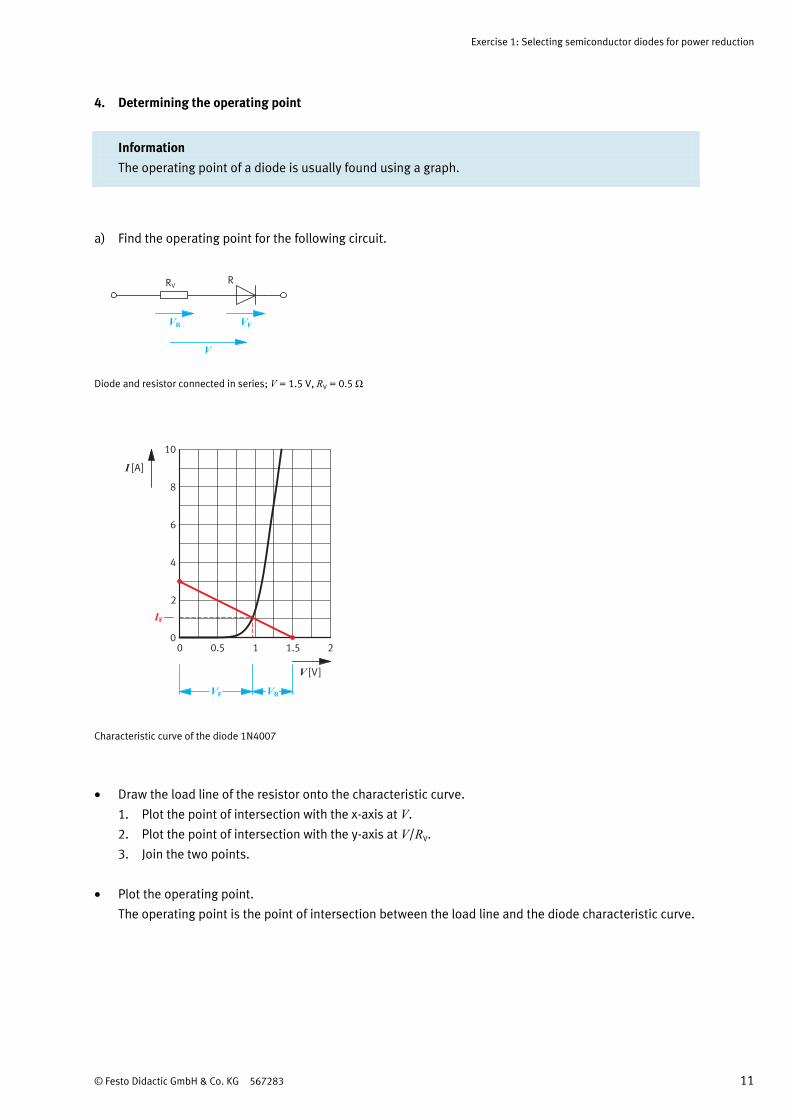
a) Find the operating point for the following circuit.
VF
RVR
VR
V
Diode and resistor connected in series; V = 1.5 V, RV = 0.5 Ω
I [A]
V [V]
0 0.5 1 1.5 20
2
4
6
8
10
IF
VF VR
Characteristic curve of the diode 1N4007
• Draw the load line of the resistor onto the characteristic curve.
1. Plot the point of intersection with the x-axis at V.
2. Plot the point of intersection with the y-axis at V/RV.
3. Join the two points.
• Plot the operating point.
The operating point is the point of intersection between the load line and the diode characteristic curve.
Exercise 1 – Selecting semiconductor diodes for power reduction
12 © Festo Didactic GmbH & Co. KG 567283
b) The operating point can be used to determine the voltage VF, the voltage VR and the current IF. Plot the
required values on the characteristic curve and read off the values.
Forward voltage VF = 0.96 V Voltage VR = 0.54 V Forward current IF = 1.07 A
5. Characteristics and ratings of semiconductor diodes
a) Find out what is meant by characteristics and ratings.
Characteristics
These are properties of a semiconductor component at a certain operating point.
Ratings
These are values which cannot be exceeded without risking immediate destruction of the component.
b) Define the meaning of the important characteristics.
Forward voltage VF
Voltage in forward direction
Forward current IF
Current in forward direction

Exercise 1: Selecting semiconductor diodes for power reduction
© Festo Didactic GmbH & Co. KG 567283 13
c) Define the meaning of the important ratings.
Repetitive peak reverse voltage VRRM
Maximum reverse voltage which can be allowed to occur repetitively
Forward surge current IFSM
Highest non-repetitive surge current of defined duration which can be allowed
Power dissipation Ptot
Maximum permissible power dissipation
d) Use the data sheet to find out the ratings and characteristics valid for the diode 1N4007.
Diode Forward voltage VF Forward current IF Repetitive peak reverse voltage VRRM
Forward surge current IFSM
1N4001 < 1.1 V 1 A 1000 V 30 A
e) Find out the meaning of “maximum RMS voltage” on the diode's data sheet.
RMS is an abbreviation of root mean square. Therefore VRMS is the maximum RMS value for reverse
voltage which can be allowed to occur repetitively.

Exercise 1 – Selecting semiconductor diodes for power reduction
14 © Festo Didactic GmbH & Co. KG 567283
6. Determining the diode for power reduction
Information When selecting rectifier diodes, the repetitive peak reverse voltage VRRM and the power dissipation
Ptot are most important. These must not exceed the ratings.
a) Use the data sheets to determine which of the three diodes can be used in this circuit. Give a reason for
your answer.
V
feff = 230 V= 50 Hz
RV
VF
R
0
2
3
1
Circuit diagram; resistor RV: 680 Ω
Given Excerpt from data sheets for diodes BAX18, 1N4148 and 1N4007
Input voltage Veff = 230 V
Forward current IFmax = 0.5 A
To be calculated Repetitive peak reverse voltage VRRM
Power dissipation Ptot
Exercise 1: Selecting semiconductor diodes for power reduction
© Festo Didactic GmbH & Co. KG 567283 15
Calculation
• Identify the maximum repetitive peak reverse voltage VRRM which can be applied to the diode.
The effective value of the AC voltage Veff = 230 V, meaning that the peak value for the AC voltage is
V = 325 V. Therefore the maximum reverse voltage which can be applied across the diode is 325 V.
• Calculate the maximum power dissipation P of the diodes at 25 °C using the data sheets.
The maximum power dissipation in the diode arises when the maximum voltage is applied at
the input.
That is applied when the input voltage reaches its peak (V = 325 V).
Plot the operating point and read off the values for VF at that operating point.
Calculating power: F FP U I= ⋅
Read VF from the relevant characteristic curve
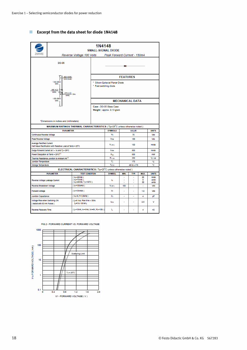
P1N4148 = no calculation necessary, as IF = 150mA
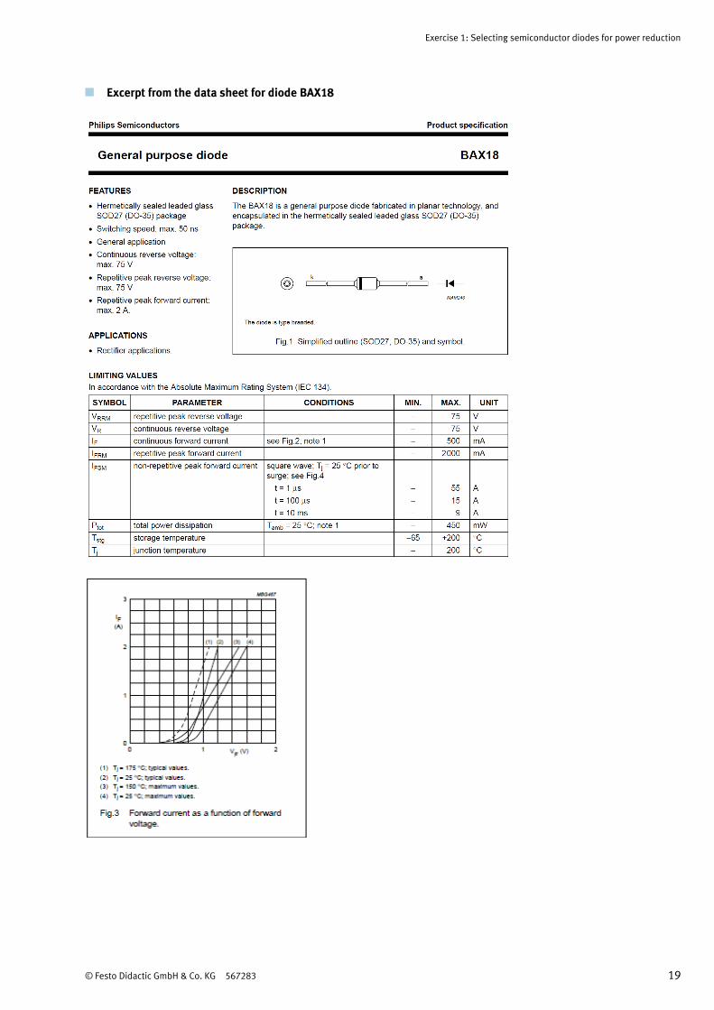
PBAX18 = 0.9 V · 0.5 A = 0.45 W = 450 mW (no calculation necessary however, as VRRM = 110 V)
P1N4007 = 0.85 V · 0.5 A = 0.425 W = 425 mW
Exercise 1 – Selecting semiconductor diodes for power reduction
16 © Festo Didactic GmbH & Co. KG 567283
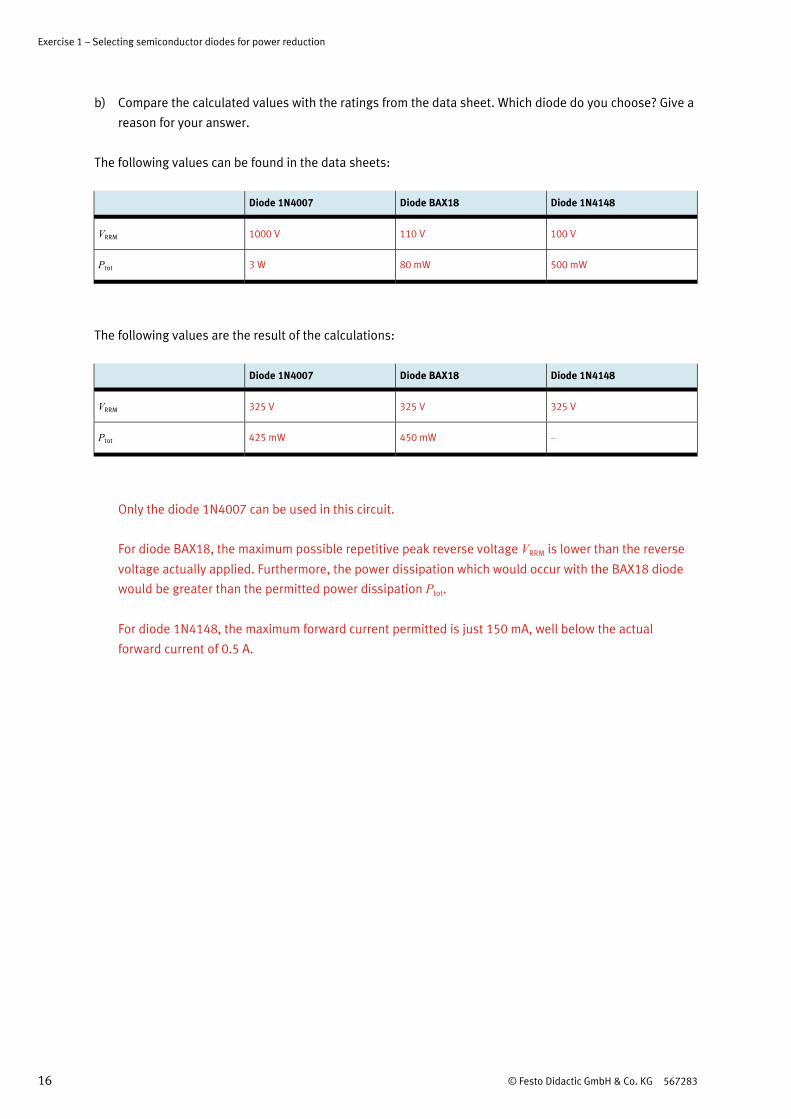
b) Compare the calculated values with the ratings from the data sheet. Which diode do you choose? Give a
reason for your answer.
The following values can be found in the data sheets:
Diode 1N4007 Diode BAX18 Diode 1N4148
VRRM 1000 V 110 V 100 V
Ptot 3 W 80 mW 500 mW
The following values are the result of the calculations:
Diode 1N4007 Diode BAX18 Diode 1N4148
VRRM 325 V 325 V 325 V
Ptot 425 mW 450 mW –
Only the diode 1N4007 can be used in this circuit.
For diode BAX18, the maximum possible repetitive peak reverse voltage VRRM is lower than the reverse
voltage actually applied. Furthermore, the power dissipation which would occur with the BAX18 diode
would be greater than the permitted power dissipation Ptot.
For diode 1N4148, the maximum forward current permitted is just 150 mA, well below the actual
forward current of 0.5 A.

Exercise 1: Selecting semiconductor diodes for power reduction
© Festo Didactic GmbH & Co. KG 567283 17
Excerpt from the data sheet for diode 1N4007
Exercise 1 – Selecting semiconductor diodes for power reduction
18 © Festo Didactic GmbH & Co. KG 567283
Excerpt from the data sheet for diode 1N4148
Exercise 1: Selecting semiconductor diodes for power reduction
© Festo Didactic GmbH & Co. KG 567283 19
Excerpt from the data sheet for diode BAX18

Exercise 1 – Selecting semiconductor diodes for power reduction
20 © Festo Didactic GmbH & Co. KG 567283