Embed Size (px)
Citation preview

Fusion Tablesaw Manual
© 2015 Laguna Tools, Inc. All rights reserved.
LAGUNA TOOLS2072 Alton ParkwayIrvine, California 92606Ph: 800.234.1976www.lagunatools.com
Model MTSAW17536110-0130Model MTSAW17536110-0130Model MTSAW17536110-0130

1
Table of contents
READ CAREFULLY BEFORE OPERATING THE MACHINE .....................................................2
10” TABLE SAW .........................................................................................................................4
GROUNDING INSTRUCTIONS ..................................................................................................5
MOVEABLE CASTER & MACHINE LEVELING ..........................................................................6
RESET PROTECTOR.................................................................................................................6
SAFETY SWITCH .......................................................................................................................7
UNPACKING ..............................................................................................................................7
CLEAR UP ..................................................................................................................................7
PLACEMENT OF THE TABLW SAW ..........................................................................................7
ASSEMBLY OF THE TABLE SAW .............................................................................................8
INSTALL BLADE GUARD .........................................................................................................10
RIVING KNIFE ..........................................................................................................................11
TABLE INSERT ........................................................................................................................12
SAW BLADE .............................................................................................................................12
FENCE ASSEMBLY .................................................................................................................12
MITER GAUGE .........................................................................................................................15
MAINTENANCE & ADJUSTMENTS .........................................................................................16
TYPE OF CUT ..........................................................................................................................19
WIRING DIAGRAMS ................................................................................................................21
PARTS DIAGRAMS ..................................................................................................................23
PARTS LIST .............................................................................................................................27

2
READ CAREFULLY BEFORE OPERATING THE MACHINE
Read this manual completely and observe all warning labels on the machine. We always make every attempt to provide a safe, reliable, easy-to-use piece of machinery. Safety, however, is ultimately the responsibility of the individual machine operator. As with any piece of machinery, the operator must exercise caution, patience, and common sense, to safely operate the machine. Before operating this product, become familiar with the safety rules in the following sections. 1. Do not operate the saw when tired, distracted, or under the effects of drugs, alcohol or any
medication that impairs reflexes or alertness. 2. The working area should be well lit, clean and free of debris. Don't use power tools in damp
or wet locations, or expose them to rain. 3. Keep children and visitors at a safe distance when the saw is in operation; do not permit
them to operate the saw. 4. Childproof and tamper proof your shop and all machinery with locks, master electrical
switches and switch keys, to prevent unauthorized or unsupervised use. 5. Stay alert! Give your work your undivided attention. Even a momentary distraction can lead
to serious injury. 6. Fine particulate dust is a carcinogen that can be hazardous to health. Work in a
well-ventilated area and whenever possible use a dust collector. Wear safety glasses that have impact resistant lenses, also use face or dust mask if cutting operation is dusty.
7. Do not wear loose clothing, gloves, bracelets, necklaces or other jewelry while the saw is in
operation. Wear protective hair covering to contain long hair and wear non-slip footwear. 8. Be sure that adjusting wrenches, tools, drinks and other clutter are removed from the
machine and/or the feed table surface before operating. 9. Keep hands well away from the blade and all moving parts. Use a brush, not hands, to clear
away chips and dust. 10. Be sure that the blade is securely installed and in the proper cutting direction before
operation. Only feed the work into a blade or cutter against the direction of rotation of the blade or cutter.
11. Be sure the blade has gained full operating speed before beginning to cut. 12. Always use a clean, properly sharpened blade. Dirty or dull blades are unsafe and can lead
to accidents. Follow instructions for lubricating and changing accessories. 13. If using a power feeder, stop the feeder before stopping the table saw. 14. Do not force stock into the blade. The saw will perform better and safely when working at the
rate for which it was designed. 15. Use suitable support when cutting stock that does not have a flat surface. Always hold stock
firmly against the fence when ripping, or against the miter gauge when cross-cutting. 16. To minimize risk of injury in the event of work piece kickback, never stand directly in-line with
the blade or in the potential kickback path of the work piece.

3
17. Avoid working from awkward or off balance positions. Do not overreach while cutting; keep both feet on floor. Never lean over or reach over the blade and never pull the work piece over the blade from behind.
18. Use out feed support or have an assistant help when ripping long material. 19. Keep blade guards in place and in working order. If a guard must be removed for
maintenance or cleaning, be sure it is properly reattached before using the tool again. Never leave the machine running with the power on when not in operation. Don't leave tool until it comes to a complete stop.
20. Use of parts and accessories NOT recommended by supplier may result in equipment
malfunction or risk of injury. 21. Never stand on machinery. Serious injury could result if the tool is tipped over or if the blade
is unintentionally contacted. 22. Always disconnect tool from power before servicing or changing accessories such as blades,
or before performing any maintenance, cleaning or adjustments, or if the machine will be left unattended.
23. Make sure that switch is in "OFF" position before plugging in the power cord. 24. Make sure the tool is properly grounded. If equipped with a 3-prong plug it should be used
with a three-pole receptacle. Never remove the third prong. 25. Do not use this saw for other than its intended use. If used for other purposes, we disclaims
any real implied warranty and holds itself harmless for any injury, which may result from that use.
26. Before using the machine, Check that no guard or other part is damaged. Carefully check
to determine that all parts of the machine will operate properly and perform there intended function. Check for alignment of moving parts, binding of moving parts, breakage of parts, mounting, and any other conditions that may affect its operation. A guard or other part that is damaged should be properly repaired or replaced.
CAUTION: This means that if precautions are not heeded, it may result in minor or moderate injury and/or
possible machine damage
WARNING: This means that if precautions are not heeded, it could result in serious injury or possibly even
death.
WARNING: The operation of any power tool can result in foreign objects being thrown into your eyes,
which can result in severe eye damage. Before beginning power tool operation, always wear
safety goggles or safety glasses with side shields and a full face shield when needed. We
recommend Wide Vision Safety Mask for use over eyeglasses or standard safety glasses with
side shields. Always use eye protection which is marked to comply with ANSI Z87.1.
4
10” TABLE SAW
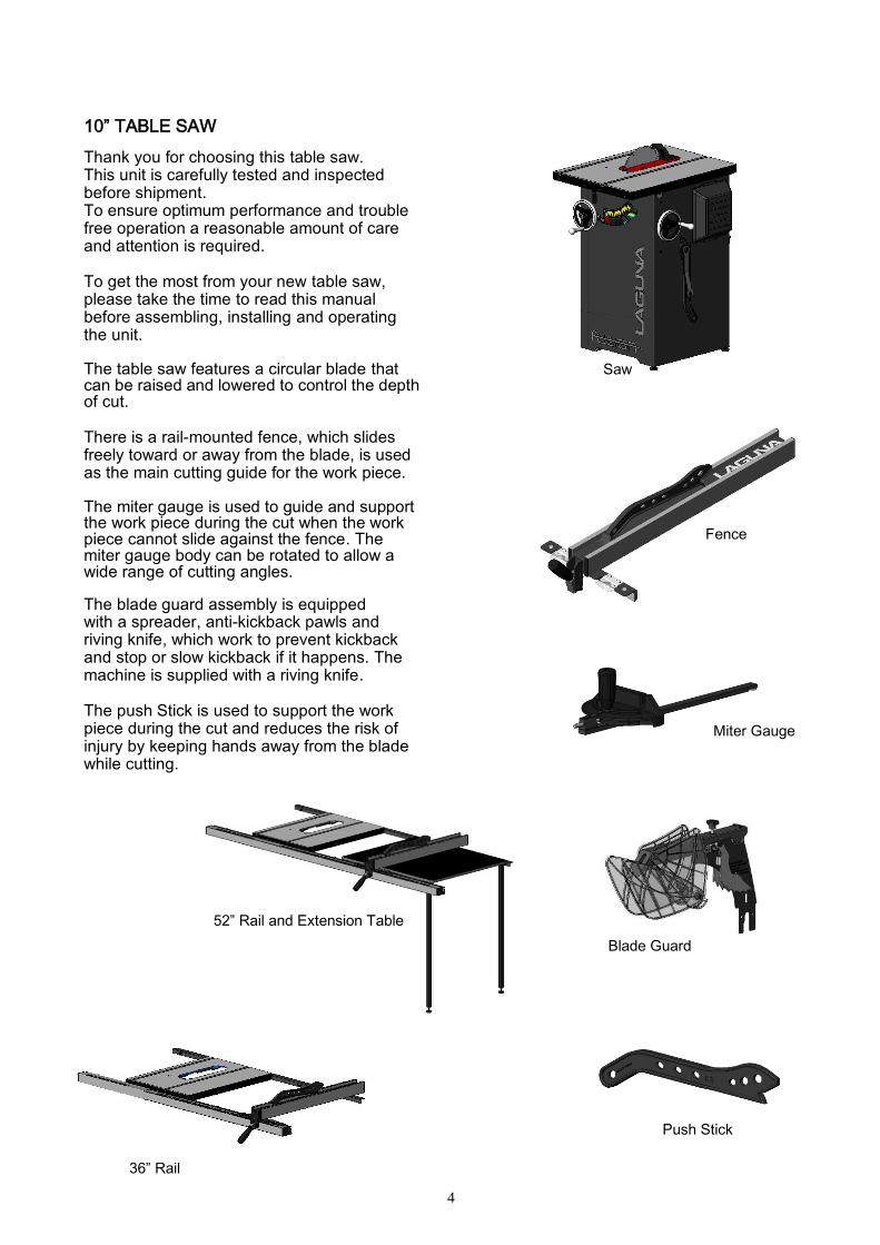
Thank you for choosing this table saw. This unit is carefully tested and inspected before shipment. To ensure optimum performance and trouble free operation a reasonable amount of care and attention is required. To get the most from your new table saw, please take the time to read this manual before assembling, installing and operating the unit. The table saw features a circular blade that can be raised and lowered to control the depth of cut.
There is a rail-mounted fence, which slides freely toward or away from the blade, is used as the main cutting guide for the work piece.
The miter gauge is used to guide and support the work piece during the cut when the work piece cannot slide against the fence. The miter gauge body can be rotated to allow a wide range of cutting angles. The blade guard assembly is equipped with a spreader, anti-kickback pawls and riving knife, which work to prevent kickback and stop or slow kickback if it happens. The machine is supplied with a riving knife.
The push Stick is used to support the work piece during the cut and reduces the risk of injury by keeping hands away from the blade while cutting.
Fence
Blade Guard
Push Stick
Miter Gauge
Saw
36” Rail
Gauge
52” Rail and Extension Table
Tab;l
5
GROUNDING INSTRUCTIONS
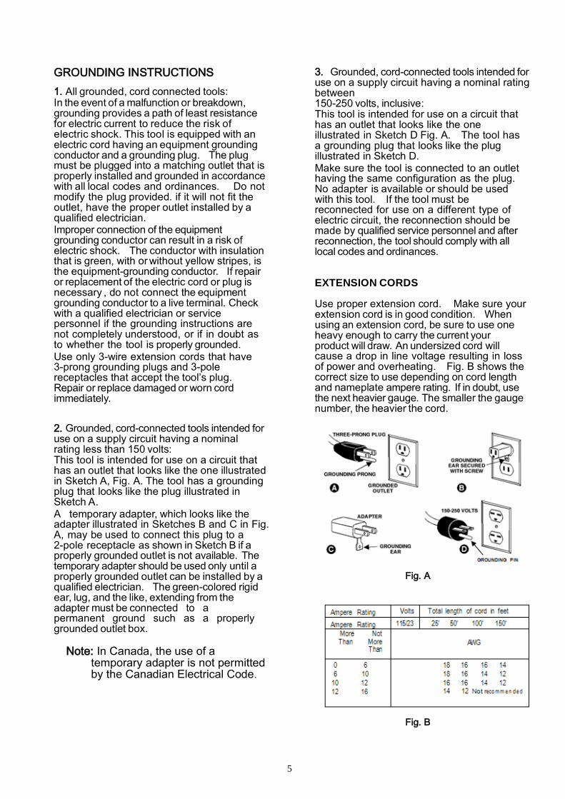
1. All grounded, cord connected tools: In the event of a malfunction or breakdown, grounding provides a path of least resistance for electric current to reduce the risk of electric shock. This tool is equipped with an electric cord having an equipment grounding conductor and a grounding plug. The plug must be plugged into a matching outlet that is properly installed and grounded in accordance with all local codes and ordinances. Do not modify the plug provided. if it will not fit the outlet, have the proper outlet installed by a qualified electrician. Improper connection of the equipment grounding conductor can result in a risk of electric shock. The conductor with insulation that is green, with or without yellow stripes, is the equipment-grounding conductor. If repair or replacement of the electric cord or plug is necessary , do not connect the equipment grounding conductor to a live terminal. Check with a qualified electrician or service personnel if the grounding instructions are not completely understood, or if in doubt as to whether the tool is properly grounded. Use only 3-wire extension cords that have 3-prong grounding plugs and 3-pole receptacles that accept the tool’s plug. Repair or replace damaged or worn cord immediately.
2. Grounded, cord-connected tools intended for use on a supply circuit having a nominal rating less than 150 volts: This tool is intended for use on a circuit that has an outlet that looks like the one illustrated in Sketch A, Fig. A. The tool has a grounding plug that looks like the plug illustrated in Sketch A. A temporary adapter, which looks like the adapter illustrated in Sketches B and C in Fig. A, may be used to connect this plug to a 2-pole receptacle as shown in Sketch B if a properly grounded outlet is not available. The temporary adapter should be used only until a properly grounded outlet can be installed by a qualified electrician. The green-colored rigid ear, lug, and the like, extending from the adapter must be connected to a permanent ground such as a properly grounded outlet box. Note: In Canada, the use of a
temporary adapter is not permitted by the Canadian Electrical Code.
3. Grounded, cord-connected tools intended for use on a supply circuit having a nominal rating between 150-250 volts, inclusive: This tool is intended for use on a circuit that has an outlet that looks like the one illustrated in Sketch D Fig. A. The tool has a grounding plug that looks like the plug illustrated in Sketch D. Make sure the tool is connected to an outlet having the same configuration as the plug. No adapter is available or should be used with this tool. If the tool must be reconnected for use on a different type of electric circuit, the reconnection should be made by qualified service personnel and after reconnection, the tool should comply with all local codes and ordinances.
EXTENSION CORDS
Use proper extension cord. Make sure your extension cord is in good condition. When using an extension cord, be sure to use one heavy enough to carry the current your product will draw. An undersized cord will cause a drop in line voltage resulting in loss of power and overheating. Fig. B shows the correct size to use depending on cord length and nameplate ampere rating. If in doubt, use the next heavier gauge. The smaller the gauge number, the heavier the cord.
Fig. A
Fig. B
6
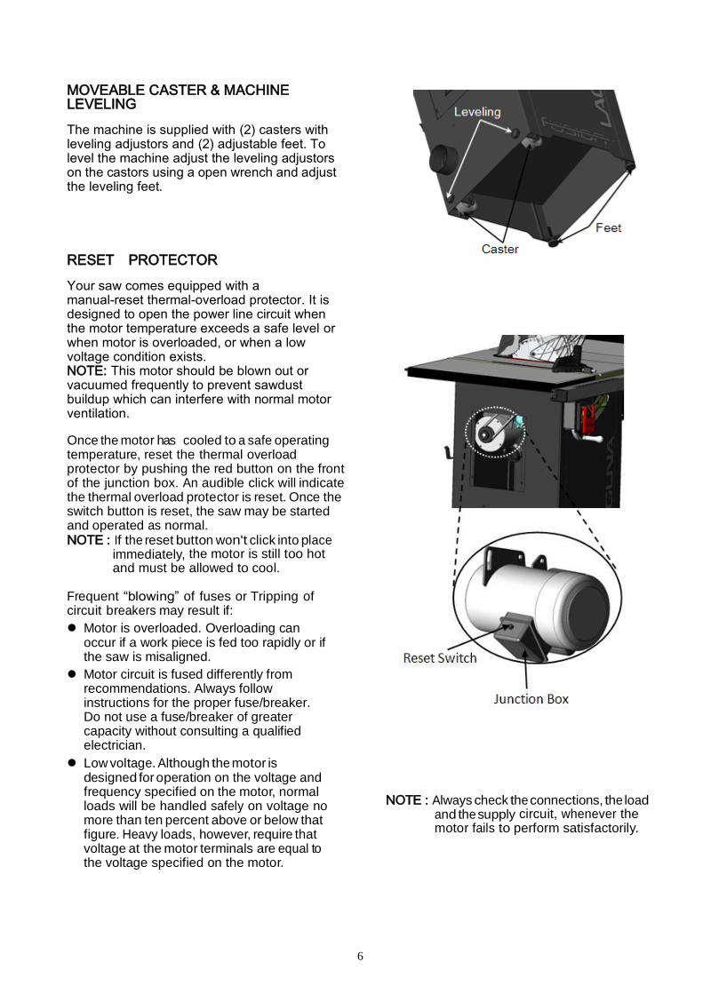
MOVEABLE CASTER & MACHINE LEVELING
The machine is supplied with (2) casters with leveling adjustors and (2) adjustable feet. To level the machine adjust the leveling adjustors on the castors using a open wrench and adjust the leveling feet.
RESET PROTECTOR
Your saw comes equipped with a manual-reset thermal-overload protector. It is designed to open the power line circuit when the motor temperature exceeds a safe level or when motor is overloaded, or when a low voltage condition exists. NOTE: This motor should be blown out or vacuumed frequently to prevent sawdust buildup which can interfere with normal motor ventilation. Once the motor has cooled to a safe operating temperature, reset the thermal overload protector by pushing the red button on the front of the junction box. An audible click will indicate the thermal overload protector is reset. Once the switch button is reset, the saw may be started and operated as normal. NOTE : If the reset button won't click into place
immediately, the motor is still too hot and must be allowed to cool.
Frequent “blowing” of fuses or Tripping of circuit breakers may result if:
Motor is overloaded. Overloading can occur if a work piece is fed too rapidly or if the saw is misaligned.
Motor circuit is fused differently from recommendations. Always follow instructions for the proper fuse/breaker. Do not use a fuse/breaker of greater capacity without consulting a qualified electrician.
Low voltage. Although the motor is designed for operation on the voltage and frequency specified on the motor, normal loads will be handled safely on voltage no more than ten percent above or below that figure. Heavy loads, however, require that voltage at the motor terminals are equal to the voltage specified on the motor.
NOTE : Always check the connections, the load
and the supply circuit, whenever the motor fails to perform satisfactorily.

7
SAFETY SWITCH
The table saw is equipped with a push-button switch that will accept a safety padlock (not included). See Fig. 1. To safeguard your machine from unauthorized operation and accidental starting by young children, the use of a padlock is required. p: With a screw driver, push a solvent-saturated rag o T-slots to remove the grease.
UNPACKING
This table saw is very heavy. Get lifting help or use power lifting equipment such as a forklift to move this Table Saw.
CLEAR UP The protective coating on the saw table prevents rust from forming during shipping and storage. Remove it by rubbing with a rag dipped in kerosene, mineral spirits or paint thinner. (Dispose of potentially flammable solvent- soaked rags according to manufacturer’s safety recommendations.)
A putty knife, held flat to avoid scratching the surface, may also be used to scrape off the coating followed by clean-up with solvent. Avoid rubbing the saw’s painted surfaces, as many solvent-based products will remove paint Fig. 2.
To prevent rust, apply a light coating of paste wax or use regular applications of any after-market surface protected or rust inhibitor.
PLACEMENT THE TABLW SAW
This machine should be installed and operated only on a solid, flat and stable floor that is able to support the weight of the saw (312 lbs-142 kgs). Using the dimensions shown as a guideline, plan for placement within your shop that will allow the operator to work unencumbered and unobstructed by foot traffic or other tools or machinery.
Fig. 1
Fig. 2
With a screw driver,
push a solvent-saturated
rag into the T-slots to
remove the grease.

8
.
,
.
ASSEMBLING THE TABLE SAW INSTALL THE TABLE EXTENSION WINGS Attach the table extension wings to the main table using 8x12mm hex head bolts (4 per wing), and 8 lock washers. Align the table extensions with the table and loosely attach the bolts. Place a straightedge on the table and extension as shown to align the extension table and then tighten down the bolts.
Note: Be sure that the table extension wings are flush with front edge.
MOUNT FENCE STORAGE BRACKETS The miter gauge and arbor wrench storage brackets are already installed on the saw. Install the fence storage brackets on the right side of the saw as shown in using two Phillips head screws and flat washers.
FRONT RAIL INSTALATION Note: The 36” front rail has 2 pieces of Tubes & a join pin but 52” Rail is single piece. 1. Loosely thread the six square head bolts
to the front of the table. 2. Do not tighten down the nuts. Leave the
square heads of the bolt protruding from the table
3. From the left side of the saw, slide the upper slot of the left (shorter) front rail onto the square head bolts
4. Set the left end of the rail flush to the outside
edge of the extension wing.
9
.
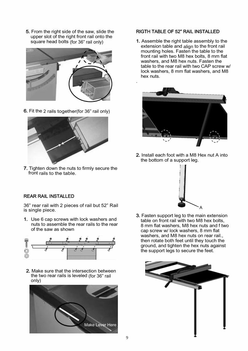
5. From the right side of the saw, slide the upper slot of the right front rail onto the square head bolts (for 36” rail only)
6. Fit the 2 rails together(for 36” rail only)
7. Tighten down the nuts to firmly secure the front rails to the table.
REAR RAIL INSTALLED 36” rear rail with 2 pieces of rail but 52” Rail is single piece. 1. Use 6 cap screws with lock washers and
nuts to assemble the rear rails to the rear of the saw as shown
2. Make sure that the intersection between the two rear rails is leveled (for 36” rail only)
RIGTH TABLE OF 52” RAIL INSTALLED 1. Assemble the right table assembly to the
extension table and align to the front rail mounting holes. Fasten the table to the front rail with two M8 hex bolts, 8 mm flat washers, and M8 hex nuts. Fasten the table to the rear rail with two CAP screw w/ lock washers, 8 mm flat washers, and M8 hex nuts.
.
2. Install each foot with a M8 Hex nut A into the bottom of a support leg.
3. Fasten support leg to the main extension
table on front rail with two M8 hex bolts, 8 mm flat washers, M8 hex nuts and f two cap screw w/ lock washers, 8 mm flat washers, and M8 hex nuts on rear rail., then rotate both feet until they touch the ground, and tighten the hex nuts against the support legs to secure the feet.
Make Lever Here
A
10
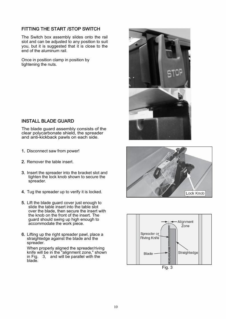
FITTING THE START /STOP SWITCH
The Switch box assembly slides onto the rail slot and can be adjusted to any position to suit you, but it is suggested that it is close to the end of the aluminum rail. Once in position clamp in position by tightening the nuts.
INSTALL BLADE GUARD
The blade guard assembly consists of the clear polycarbonate shield, the spreader and anti-kickback pawls on each side.
1. Disconnect saw from power!
2. Remover the table insert.
3. Insert the spreader into the bracket slot and tighten the lock knob shown to secure the spreader.
4. Tug the spreader up to verify it is locked.
5. Lift the blade guard cover just enough to slide the table insert into the table slot over the blade, then secure the insert with the knob on the front of the insert. The guard should swing up high enough to accommodate the work piece.
6. Lifting up the right spreader pawl, place a straightedge against the blade and the spreader.
When properly aligned the spreader/riving knife will be in the "alignment zone," shown in Fig. 3, and will be parallel with the blade.
Fig. 3

11
LOOSEN LOCK KNOB If you could not loosen the knob by hands, use the arbor wrench. See Fig. 4
ANTI-KICK BACK PAWL The anti-kickback pawls allow the work piece to travel in only one direction. If the work piece moves backwards, the pawls will dig into the work piece to slow or stop it Fig. 5. The pawls must return to their bottom-most position after pivoting. Note: The right pawl is designed to tilt slightly away from the blade guard assembly to prevent the pawl from catching in the table insert.
If the pawls fail to return to the bottom position, the pivot spring may have been dislodged or broken and will need to be fixed/replaced.
RIVING KNIFE
Use the riving knife for all non-through cuts made with a standard table saw blade or dado blade. Use the riving knife for those special operations where the blade guard or its components get in the way of safe operation, such as with very narrow cuts. The key difference between the spreader and the riving knife is that the riving knife mounts below the blade's highest point of rotation The riving knife must be kept within the range shown in Fig. 6. A 10" blade is required for operations that use a riving knife.
WARNING: In order to work properly, the riving knife cannot be bent or misaligned with the blade. If the riving knife gets accidentally bent, take the time to straighten it or just replace it. Using a bent or misaligned riving knife will increase the risk of kickback! WARNING: ALWAYS TURN OFF AND UNPLUG THE SAW BEFORE REMOVING/ INSTALLING A RIVING KNIFE.
Fig. 4
Fig. 5
Fig. 6
Fig. 7
!
!
!
!
12
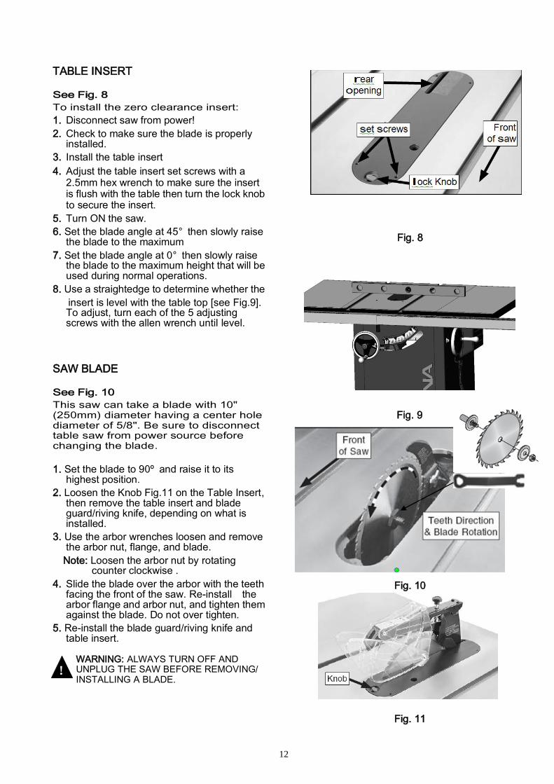
TABLE INSERT
See Fig. 8
To install the zero clearance insert:
1. Disconnect saw from power!
2. Check to make sure the blade is properly installed.
3. Install the table insert
4. Adjust the table insert set screws with a 2.5mm hex wrench to make sure the insert is flush with the table then turn the lock knob to secure the insert.
5. Turn ON the saw.
6. Set the blade angle at 45° then slowly raise the blade to the maximum
7. Set the blade angle at 0° then slowly raise the blade to the maximum height that will be used during normal operations.
8. Use a straightedge to determine whether the
insert is level with the table top [see Fig.9]. To adjust, turn each of the 5 adjusting screws with the allen wrench until level.
SAW BLADE
See Fig. 10
This saw can take a blade with 10" (250mm) diameter having a center hole diameter of 5/8". Be sure to disconnect table saw from power source before changing the blade.
1. Set the blade to 90º and raise it to its highest position.
2. Loosen the Knob Fig.11 on the Table Insert, then remove the table insert and blade guard/riving knife, depending on what is installed.
3. Use the arbor wrenches loosen and remove the arbor nut, flange, and blade.
Note: Loosen the arbor nut by rotating counter clockwise .
4. Slide the blade over the arbor with the teeth facing the front of the saw. Re-install the arbor flange and arbor nut, and tighten them against the blade. Do not over tighten.
5. Re-install the blade guard/riving knife and table insert.
WARNING: ALWAYS TURN OFF AND UNPLUG THE SAW BEFORE REMOVING/ INSTALLING A BLADE.
Fig. 8
Fig. 9
Fig. 10
Fig. 11
!
!
13
.
.
,
FENCE ASSEMBLY
ALIGN THE FENCE PARALLEL TO THE BLADE
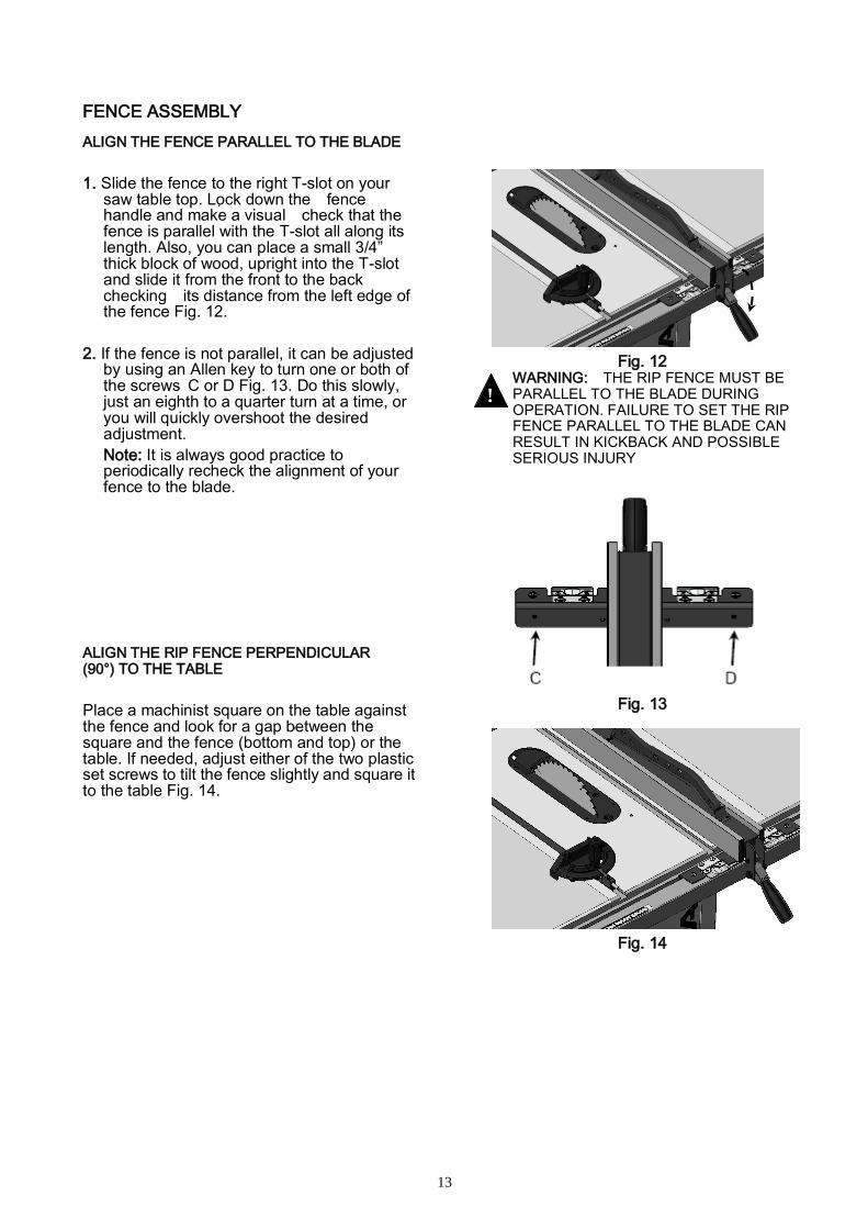
1. Slide the fence to the right T-slot on your saw table top. Lock down the fence handle and make a visual check that the fence is parallel with the T-slot all along its length. Also, you can place a small 3/4” thick block of wood, upright into the T-slot and slide it from the front to the back checking its distance from the left edge of the fence Fig. 12.
2. If the fence is not parallel, it can be adjusted by using an Allen key to turn one or both of the screws C or D Fig. 13. Do this slowly, just an eighth to a quarter turn at a time, or you will quickly overshoot the desired adjustment.
Note: It is always good practice to periodically recheck the alignment of your fence to the blade.
ALIGN THE RIP FENCE PERPENDICULAR (90°) TO THE TABLE
Place a machinist square on the table against the fence and look for a gap between the square and the fence (bottom and top) or the table. If needed, adjust either of the two plastic set screws to tilt the fence slightly and square it to the table Fig. 14.
Fig. 12 WARNING: THE RIP FENCE MUST BE PARALLEL TO THE BLADE DURING OPERATION. FAILURE TO SET THE RIP FENCE PARALLEL TO THE BLADE CAN RESULT IN KICKBACK AND POSSIBLE SERIOUS INJURY
Fig. 13
Fig. 14
!
!

14
.
.
LEVEL THE FENCE The fence should be parallel to the table and sit approximately 2mm above the table’s surface (so the fence will not scratch the table and a thin work piece will not get stuck or jammed under the fence). To level and adjust the height of the fence: 1. Loosen the hex nut F on the leveling foot G
located under the rear end of the fence Fig. 15.
2. Raise or lower the leveling foot until there
is a spacing of 2 mm (approx.) between the bottom of the fence and the table, then tighten the hex nut to lock the setting of the leveling foot.
3. If needed, to level the fence, adjust the
plastic set screws E equally, thereby raising or lowering the front of the fence an equal amount on either side so as not to undo the previous perpendicular adjustment Fig. 16.
ADJUST & ALIGN RIP FENCE POINTER Set blade to 90° and raise it to the maximum height. Move the fence till it lightly touches the right side of the blade and push down the locking lever to lock the fence in place. With the fence locked in place against the blade, loosen the pointer screws B Line up the reference line on the pointer with the zero point on the tape and re-tighten the pointer screws Fig. 17. Note: When changing blades, re-align the
pointer with the zero points on the tapes to account for thinner or thicker blades.
DUST COLLECTOR There is a 4" dust outlet located on the lower left of the saw cabinet. This allows for the connection to a dust collection system (not included) Fig. 18.
1. Fit the 4" dust hose over the dust port, (not included) and secure in place with a hose clamp.
2. Make sure the hose could not come off. Note: A tight fit is necessary for proper
performance.
WARNING: ALWAYS TURN ON THE DUST
COLLECTOR BEFORE STARTING THE SAW AND STOP THE SAW BEFORE TURNING OFF
THE DUST COLLECTOR.
Fig. 15
Fig. 16
Fig. 17
Fig. 18
E
!
!

15
PUSH STICK
Always use a push stick Fig. 19 to reduce the risk of injury. This will keep your hands away from the blade while cutting. To maintain control when cutting large work pieces, start the cut by feeding by hand then use a push sticks to finish the cut.
MITER GAUGE
The miter gauge is equipped with stop screws that allow you to easily adjust the miter gauge +45,° 90° and 45° See Fig. 20
To use setting to other than 90°, loosen the lock knob A by turning it counter-clockwise, pull the stop-lock pin B Fig. 21rotate the miter head to 45°, or any angle shown on the numerical guide. Turn the lock knob clockwise to tighten it. To check the accuracy of the miter gauge’s factory set- tings, set it at 90° and check it with an L-square or T-square. To verify the setting, make a test cut in scrap stock and then use a square to check the cut piece. Repeat adjustment if necessary.
Fig. 19
Fig. 20
Fig. 21
16
MAINTENANCE & ADJUSTMENTS
PERIODIC MAINTENANCE • Inspect/test the ON/OFF switch before
each use. Do not operate the saw with a damaged switch - replace a damaged switch immediately
• Inspect the saw blade for damage or chipped teeth before each use. Replace a damaged or chipped blade immediately. Never operate the saw with a damaged or chipped blade
• Keep the saw table clean and free of dust, pitch or glue. An occasional light coating of paste wax can be use to protect the cast-iron surface. Ask our local distributor for suggestions on table top cleaners and cast-iron surface protection, based on what is readily available in your area.
• Occasionally open the cabinet door and brush off and vacuum out accumulated dust from inside the cabinet and on the blade tilting gears and on or around the motor.
• Periodically inspect the power cord and plug for damage. To minimize the risk of electric shock or fire, never operate the saw with a damaged power cord or plug. Replace a damaged power cord or plug at the first sign of damage.
• To minimize airborne dust particles periodically inspect all dust collection fittings – retighten as needed.
WARNING: MAKE SURE THE SAW HAS
BEEN TURNED OFF AND UNPLUGGED FROM
THE POWER SOURCE BEFORE PERFORMING
ANY MAINTENANCE.
LUBRICATION
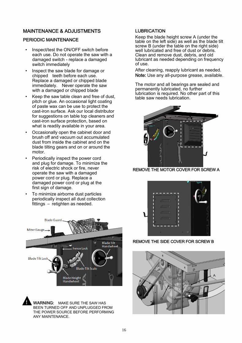
Keep the blade height screw A (under the table on the left side) as well as the blade tilt screw B (under the table on the right side) well lubricated and free of dust or debris. Clean and remove dust, debris, and old lubricant as needed depending on frequency of use.
After cleaning, reapply lubricant as needed.
Note: Use any all-purpose grease, available. The motor and all bearings are sealed and permanently lubricated, no further lubrication is required. No other part of this table saw needs lubrication.
REMOVE THE MOTOR COVER FOR SCREW A
REMOVE THE SIDE COVER FOR SCREW B
!
!
17
.
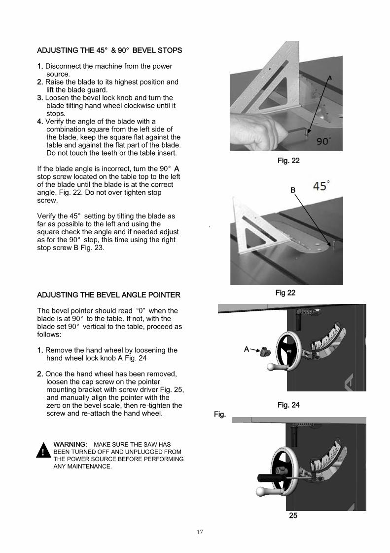
ADJUSTING THE 45° & 90° BEVEL STOPS 1. Disconnect the machine from the power
source. 2. Raise the blade to its highest position and
lift the blade guard. 3. Loosen the bevel lock knob and turn the
blade tilting hand wheel clockwise until it stops.
4. Verify the angle of the blade with a combination square from the left side of the blade, keep the square flat against the table and against the flat part of the blade. Do not touch the teeth or the table insert.
If the blade angle is incorrect, turn the 90° A stop screw located on the table top to the left of the blade until the blade is at the correct angle. Fig. 22. Do not over tighten stop screw. Verify the 45° setting by tilting the blade as far as possible to the left and using the square check the angle and if needed adjust as for the 90° stop, this time using the right stop screw B Fig. 23. ADJUSTING THE BEVEL ANGLE POINTER The bevel pointer should read “0” when the blade is at 90° to the table. If not, with the blade set 90° vertical to the table, proceed as follows: 1. Remove the hand wheel by loosening the
hand wheel lock knob A Fig. 24 2. Once the hand wheel has been removed,
loosen the cap screw on the pointer mounting bracket with screw driver Fig. 25, and manually align the pointer with the zero on the bevel scale, then re-tighten the screw and re-attach the hand wheel.
WARNING: MAKE SURE THE SAW HAS
BEEN TURNED OFF AND UNPLUGGED FROM
THE POWER SOURCE BEFORE PERFORMING
ANY MAINTENANCE.
Fig. 22
Fig 22
Fig. 23
Fig. 24
Fig.
25
!
!
B
b
b
b
A
A

18
.
BLADE HEIGHT ADJUSTMENT
The blade height adjustment hand wheel A is located on the front of the saw and there is a lock knob B on the hand wheel that allows you to lock the wheel and secure the blade at the desired height Fig. 26. To raise or lower the blade:
1. Loosen the blade height lock knob B by turning counter clockwise.
2. To raise the blade: turn the hand wheel clockwise. To lower the blade: turn the hand wheel counter clockwise.
3. With the blade set to the desired height, tighten the lock knob by turning clockwise to lock the blade.
BLADE TILT /BEVEL ADJUSTMENT The blade tilt (bevel) adjustment hand wheel C is located on the side of the saw. The bevel locking lever D is located under the table at the front of the saw and allows the user to lock the tilting mechanism and secure the blade at the desired angle Fig. 27. To change the angle of the blade:
1. Loosen the bevel locking handle D by turning it counter-clockwise.
2. Turn the hand wheel C left or right as
required to set the blade to the desired angle. The blade can be tilted to the left anywhere from 0° (90° to the table) to 45°.
3. With the blade tilted to the desired angle,
tighten the bevel locking handle by turning it clockwise to lock the tilting mechanism and secure the blade.
WARNING: TO LIMIT YOUR EXPOSURE TO
THE BLADE AND ALSO TO MAXIMISE THE
EFFECTIVENESS OF THE ANTI-KICKBACK
PAWLS (WHEN USING THE RIVING STYLE
SPLITTER & BLADE GUARD), NEVER HAVE
MORE BLADE HEIGHT THAN IS REQUIRED TO
COMPLETE THE CUT. WHEN SETTING THE
BLADE HEIGHT FOR THROUGH-CUTS (CUTS
ALL THE WAY THROUGH THE THICKNESS OF
A BOARD) SET THE HEIGHT OF THE
BLADE TO ROUGHLY 1/4" HIGHER THAN
THE THICKNESS OF THE BOARD.
3
Fig. 26
Fig. 27
!
!
A
B
C
D
19
TYPE OF CUT
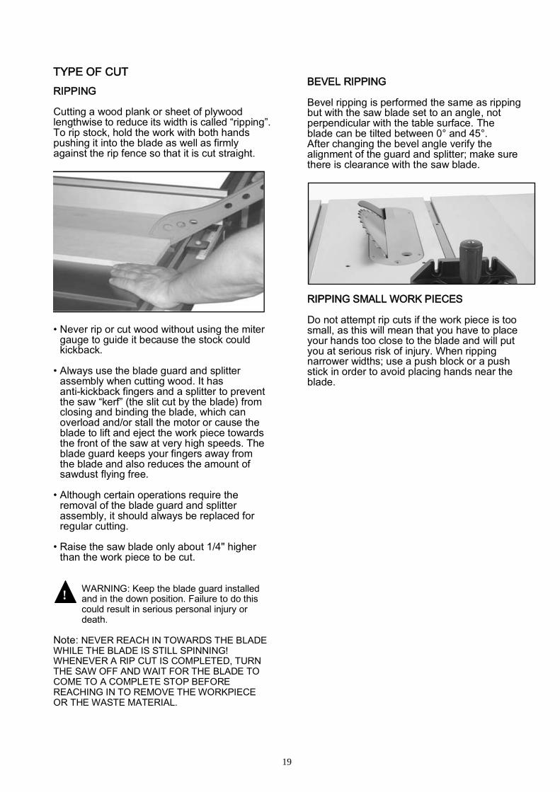
RIPPING Cutting a wood plank or sheet of plywood lengthwise to reduce its width is called “ripping”. To rip stock, hold the work with both hands pushing it into the blade as well as firmly against the rip fence so that it is cut straight.
• Never rip or cut wood without using the miter
gauge to guide it because the stock could kickback.
• Always use the blade guard and splitter
assembly when cutting wood. It has anti-kickback fingers and a splitter to prevent the saw “kerf” (the slit cut by the blade) from closing and binding the blade, which can overload and/or stall the motor or cause the blade to lift and eject the work piece towards the front of the saw at very high speeds. The blade guard keeps your fingers away from the blade and also reduces the amount of sawdust flying free.
• Although certain operations require the
removal of the blade guard and splitter assembly, it should always be replaced for regular cutting.
• Raise the saw blade only about 1/4" higher
than the work piece to be cut.
WARNING: Keep the blade guard installed and in the down position. Failure to do this could result in serious personal injury or death.
Note: NEVER REACH IN TOWARDS THE BLADE WHILE THE BLADE IS STILL SPINNING! WHENEVER A RIP CUT IS COMPLETED, TURN THE SAW OFF AND WAIT FOR THE BLADE TO COME TO A COMPLETE STOP BEFORE REACHING IN TO REMOVE THE WORKPIECE OR THE WASTE MATERIAL.
BEVEL RIPPING Bevel ripping is performed the same as ripping but with the saw blade set to an angle, not perpendicular with the table surface. The blade can be tilted between 0° and 45°. After changing the bevel angle verify the alignment of the guard and splitter; make sure there is clearance with the saw blade.
RIPPING SMALL WORK PIECES Do not attempt rip cuts if the work piece is too small, as this will mean that you have to place your hands too close to the blade and will put you at serious risk of injury. When ripping narrower widths; use a push block or a push stick in order to avoid placing hands near the blade.
!
!

20
,
CROSS CUTTING Cutting against the grain, to shorten the length of a board, is crosscutting. With some smaller sized and rectangular pieces, you often have the choice of ripping or crosscutting. Always use the miter gauge, when crosscutting; never cut a piece unsupported. The miter gauge may be used in either slot, but most operators prefer the left groove for typical work. When the blade is tilted for bevel cutting, use the table slot that does not cause interference with your hand or the saw blade guard Fig. 28
BEVEL CROSS CUTTING
This procedure is the same as cross cutting except that the blade is set to an angle other than 0. After changing the bevel angle, verify the alignment of the guard and splitter and verify that there is clearance with the saw blade Fig. 29.
MITER CUTS
This operation is the same as cross cutting, except the miter gauge is set to an angle other than 0. Hold the work piece firmly against the miter gauge and feed the work piece slowly into the blade to prevent it from moving during the cut Fig. 30.
Fig. 28
Fig. 29
Fig. 30

21
WIRING DIAGRAMS
1.75HP.110/220V.60HZ.1PH

22
2HP.220V.60HZ.1PH
23
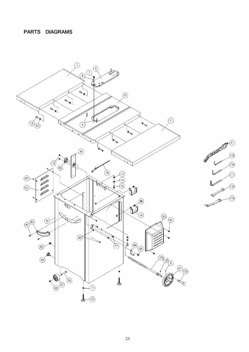
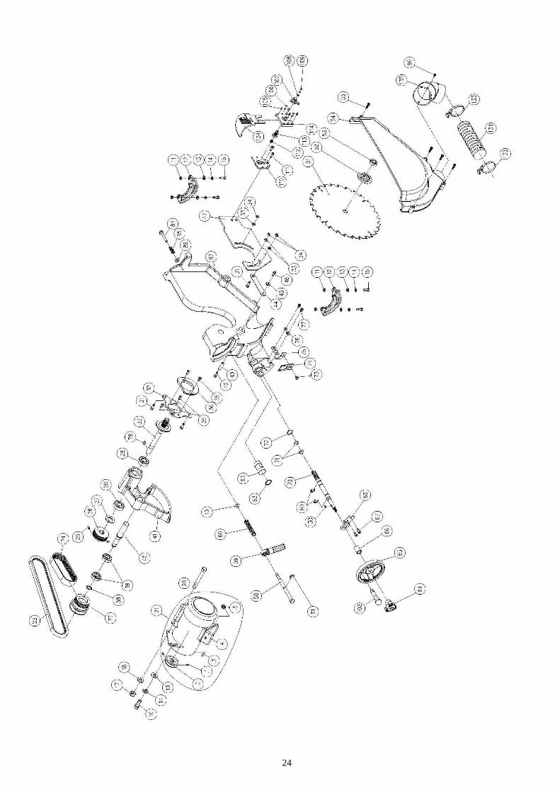
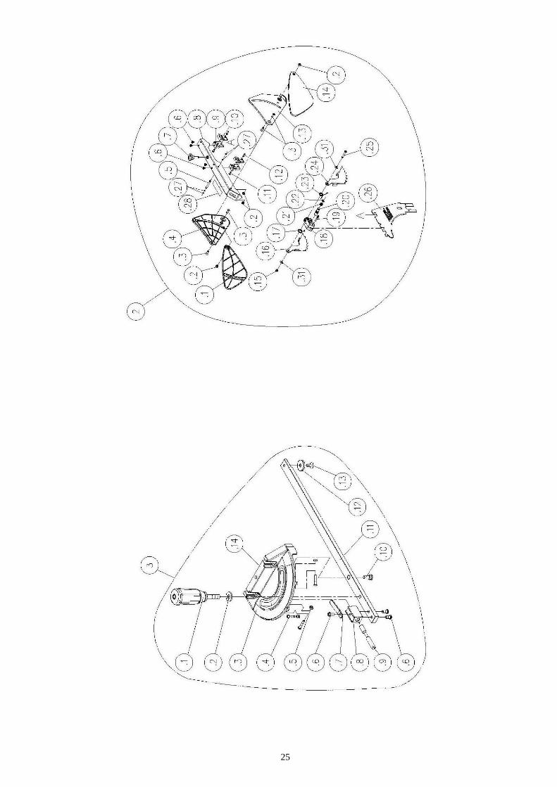
PARTS DIAGRAMS
24
25

26

27
PARTS LIST Key Part No. Descriptions Q'ty
1 923135-000 Rip Fence Assembly 1
1.1 250483-615 End Cap 4
1.2 310100-909 Adaptor 2
1.3 000002-308 Hex. screw M6*1.0P*45 1
1.4 171993-904 Bracket 1
1.5 250602-621 Frictional Plate 1
1.6 048701-101 Square Bolt M8*1.25P*20 6
1.7 250799-620 Pointer 2
1.8 001101-205 Round Head Tapping Screw M3*1.06P*6 4
1.9 000304-210 Pan Head Screw M6*1.0P*6 4
1.10 173142-308 Fence Body 1
1.11 008005-100 Hex Nut M6*1.0P 1
1.12 250587-615 Frictional Wheel 1
1.13 008006-100 Hex Nut M8*1.25P 6
1.14 006001-049 Flat Washer 8.5*16*2t 6
1.15 250472-621 Plastic Set Screw 2
1.16 000004-306 Hex. screw M10*1.5P*50 1
1.17 230301-615 Handle 1
1.18 922141-000 Compress Cam Assembly 1
1.19 250471-621 Frictional Plate 2
1.20 002103-103 Flat Head Screw M6*1.0P*8 2
1.21 172341-904 Bracket for Frictional Plate 1
1.22 008308-100 Anti-loose Nut M10*1.5P 1
1.23 008304-100 Anti-loose Nut M6*1.0P 1
1.24 001902-109 Set screw M6*1.0P*6 2
1.25 172847-905 Bracket for Pointer 2
1.32 270007-901 Spring Plate 2
1.33 000302-101 Pan Head Screw M4*0.7P*6 4
2 923055-000 Blade Guard Assembly 1
2.1 250821-620 Protective Shield -Left 1
2.2 008302-200 Anti-loose Nut M5*0.8P 4
2.3 000402-207 Flat Head Screw M5*0.8P*15 4
2.4 250820-620 Left Cover 1
2.5 360962-901 Pin 1
2.6 000303-101 Pan Head Screw M5*0.8P*6 4
2.7 230336-615 Bolt 1

28
Key Part No. Descriptions Q'ty
2.8 171154-904 Rod 1
2.9 130270-903 Rod Bracket -Left 2
2.10 130271-903 Rod Bracket -Right 2
2.11 000302-103 Pan Head Screw M4*0.7P*10 2
2.12 360960-901 Pin 2
2.13 250818-620 Right Cover 1
2.14 250819-620 Protective Shield -Right 1
2.15 008302-100 Anti-loose Nut M5*0.8P 1
2.16 171378-904 Anti-Kick Finger -Left 1
2.17 280162-901 Spring 1
2.18 090149-910 Block 1
2.19 360864-000 Pin 1
2.20 360865-901 Spreader Shaft 1
2.21 280160-901 Spring 1
2.22 010204-000 Retaining Ring ETW-7 1
2.23 280163-901 Spring 1
2.24 171379-904 Anti-Kick Finger -Right 1
2.25 000303-110 Pan Head Screw M5*0.8P*30 1
2.26 171153-904 Spreader 1
2.27 043323-000 O-Ring P3 4
2.28 573543-000 Warning Label 1
2.31 006001-012 Flat Washer 5.3*12*1.0t 2
3 920719-000 Miter Gauge Assembly 1
3.1 920720-000 Miter Gauge Handle Assembly 1
380202-905 Nut 1
250292-000 Handle 1
000003-217 Hex. screw M8*1.25P*75 1
3.2 006001-049 Flat Washer 8.5*16*2.0t 1
3.3 090109-008 Miter gauge body 1
3.4 000302-108 Pan Head Screw M4*0.7P*20 3
3.5 008002-100 Hex Nut M4*0.7P 3
3.6 000303-103 Pan Head Screw M5*0.8P*10 3
3.7 250226-620 Pointer 1
3.8 130057-903 Spacer 1
3.9 360447-901 Angle Set Bar 1
3.10 290023-901 Shoulder Screw 1
3.11 380079-904 Slot Bar 1

29
Key Part No. Descriptions Q'ty
3.12 380069-901 Ring 1
3.13 230217-901 Flat Head Screw M6*1.0P*8 1
3.14 571614-000 Miter Scale 1
4 051050-000 Extension Table 2
5 520001-311 Box 710*320*50 2
6 922130-000 Table Insert Assembly 1
7 250822-616 Bolt 1
8 001901-104 Set screw M5*0.8P*12 5
9 001903-103 Set screw M8*1.25P*20 2
10 051136-000 Table 1
11 008006-100 Hex Nut M8*1.25P 6
12 051135-000 Trunnion Support 2
13 006001-049 Flat Washer 8.5*16*2.0t 15
14 006305-100 Spring Washer 8.2*15.4 8
15 000003-105 Hex. screw M8*1.25P*25 4
16 000003-104 Hex. screw M8*1.25P*20 12
17 008308-100 Anti-loose Nut M10*1.5P 1
18 006001-071 Flat Washer 10*25*3.0t 1
19 006001-041 Flat Washer 8.2*22*3.0t 2
20 000004-208 Hex. screw M10*1.5P*80 1
21.1 900804-000 Motor Assembly 2HP*1PH 1
21.2 900807-000 Motor Assembly 1.75HP*1PH 1
22.1 937646-000 Magnetic Switch Assembly 230V 1
22.2 937653-000 Magnetic Switch Assembly 120V 1
23 014403-000 V-Belt 17-320 1
24 014342-000 Poly V-Belt 125J-6 1
25 001902-101 Set screw M6*1.0P*10 2
26 380997-000 Pulley 1
27 006003-100 Flat Washer 15.5*21*0.8 1
28 030206-002 Ball Bearing 6202 2
29 012003-006 Key 5*5*18 1
30 380996-901 Arbor 1
31 000002-104 Hex. screw M6*1.0P*20 3
32 172944-904 Fixed Plate 1
33 006001-034 Flat Washer 6.7*16*2.0t 3
34 008304-100 Anti-loose Nut M6*1.0P 3
35 000702-102 Socket Hex. Screw M6*1.0P*12 4

30
Key Part No. Descriptions Q'ty
36 130272-903 Clamper Support 1
37 380998-902 Pulley 1
38 010006-000 Retaining Ring STW-15 1
39 030213-002 Bearing 6002 2
40 360964-000 Long Rod 1
41 051099-000 Shaft Gear 1
42 000104-114 Cap Screw M8*1.25P*50 1
43 160002-903 Bushing 1
44 172946-904 Rod 1
45 160067-000 Packing 1
46 000001-109 Hex. screw M5*0.8P*12 1
47 172941-904 Stretch Out Plate 1
48 000002-101 Hex. Head Screw M6*1.0P*12 2
49 170541-904 Slide Shelf 2
50.1 923132-000 36" Rail Assy.
.1 001803-102 CAP Screw w/ Spring Washer M8*1.25P*20/8.2*15.4 6
.2 006001-049 Flat Washer 8.5*16*2.0t 12
.3 008006-100 Hex Nut M8*1.25P 12
.4 048701-101 Square Bolt M8*1.25P*20 6
.6 850673-000 Rail End Cap Assembly 1
.7 250698-615 End Cap - Left 1
.8 250699-615 End Cap - Right 1
.9 001102-604 Self-Tapping Screw M4*1.59P*12 4
.11 172342-904 Rear Rail- Left 1
.12 172343-904 Rear Rail- Right 1
.13 310163-909 Front Rail - Left 1
.14 310164-909 Front Rail - Right 1
.15 360249-905 Pin 2
.16 573035-000 Length Scale ( L ) 0"~12" 1
.17 573036-000 Length Scale ( R ) 0"~36" 1
50.2 923133-000 52" Rail with Right Table Assembly 1
50.2.1 923141-000 52" Rail Assembly 1
.1 001803-102 CAP Screw w/ Spring Washer M8*1.25P*20/8.2*15.4 6
.2 006001-049 Flat Washer 8.5*16*2.0t 12
.3 008006-100 Hex Nut M8*1.25P 12
.4 048701-101 Square Bolt M8*1.25P*20 6
.6 250698-615 End Cap - Left 1

31
Key Part No. Descriptions Q'ty
.7 250699-615 End Cap - Right 1
.8 001102-604 Self-Tapping Screw M4*1.59P*12 4
.9 173138-308 Rear rail 1
.10 310274-909 Front Rail 1
.11 573035-000 Length Scale ( L ) 0"~12" 1
.12 572537-000 Length Scale ( R ) 52" 1
50.2.2 923142-000 Extension Table Assembly 1
.1 001803-102 CAP Screw w/ Spring Washer M8*1.25P*20/8.2*15.4 4
.2 006001-049 Flat Washer 8.5*16*2.0t 8
.3 008006-100 Hex Nut M8*1.25P 10
.4 048701-101 Square Bolt M8*1.25P*20 4
.5 230041-000 Leveling foot 2
.7 440038-000 PDF Table 1
.8 173139-902 Brace 4
.9 230086-901 Self-Tapping screw 8
.10 190205-308 Steel Tube 2
51 390017-000 Saw Blade 1
52 170518-901 Saw Blade clamp 1
53 380205-901 Nut TW5/8"-12 1
54 250836-615 Dust Guard 1
55 000303-210 Pan Head Screw M5*0.8P*30 4
58 360653-902 Fix Shaft Bolt 1
59 920693-000 Handle Assembly 1
60 280060-000 Spring 1
61 010205-000 Retaining Ring ETW-8 1
62 010115-000 Retaining Ring RTW-24 1
63 360695-000 Guide shaft 1
64 920703-000 Fixing Knob 1
65 240061-008 Handwheel 2
66 190054-902 Spacer 1
67 000102-104 Cap Screw M5*0.8P*12 2
68 170914-902 Fence Block 1
69 010208-000 Retaining Ring ETW-12 2
70 361098-000 Elevated Screw 1
71 043303-000 O-Ring P12 2
72 006705-100 Wave Washer WW-16 1
73 001601-101 Round Head Screw w/Washer M4*0.7P*8/4*10*0.8t 1

32
Key Part No. Descriptions Q'ty
74 170912-156 Pointer 1
75 172945-902 Bracket 1
76 006001-022 Flat Washer 6.3*13*1.0t 2
77 000303-104 Pan Head Screw M5*0.8P*12 4
78 230297-615 Fixing Pin 2
79 008302-100 Anti-loose Nut M5*0.8P 2
80 170932-901 Clamper Support 1
81 170933-901 Fixed Plate 1
82 000302-203 Pan Head Screw M4*0.7P*10 10
83 250248-615 Bracket 1
84 000902-405 Hex. Screw w/washer M6*1.0P*40 1
85 280059-000 Spring 1
86 006001-026 Flat Washer 6.4*20*3.0t 1
87 051098-000 Turning 1
88 049201-102 Hex Screw w/Washer M8*1.25P*12 1
88 049201-102 Hex Screw w/Washer M8*1.25P*12 2
89 170965-904 Fix Plate 1
90 001103-901 Round Head Screw M4.5*1.81P*9 5
91 173557-000 Case 1
92 020004-000 Strain Relief SB8R-1 1
93 173024-000 Side Cover 1
94 230334-615 Push Sticks 1
96 000003-316 Hex. screw M8*1.25P*60 2
97 250399-615 Wheel 2
98 008306-100 Anti-loose Nut M8*1.25P 2
99 004001-101 Knob 5/16"-18NC*3/4" 2
100 250362-615 Motor Cover 1
101 923529-000 Leadscrew Assembly 1
102 230173-916 Handle 2
104 171430-904 Riving Knife 1
105 001902-110 SET Locking screw M6*1.0P*8 4
106 000804-106 Round Head Screw M5*0.8P*16 2
107 090244-920 Knob 1
108 006302-100 Spring Washer 5.1*9.3 1
109 002503-101 Round Head Socket Lock Screw M5*0.8P*12 1
110 130268-903 Bracket for Riving Knife 1
111 000104-102 Cap Screw M8*1.25P*10 2

33
Key Part No. Descriptions Q'ty
112 280186-901 Spring 1
113 380988-901 Knob 1
114 130269-903 Block 1
115 040002-000 Hex. Wrench 2.5mm 1
116 040004-000 Hex. Wrench 4mm 1
117 040006-000 Hex. Wrench 6mm 1
118 040203-000 Open Wrench 11*13 1
119 170399-904 Spanner 2
128 006001-033 Flat Washer 6.7*16*1.0t 2
129 008603-100 Square Nut M6*1.0P 2
130 012002-005 Key 4*4*12 2
131 230041-000 Leveling foot 2
132 920687-000 Adapter 1
133 042608-000 Clip 2
134 042615-000 Dust Tube 1

Laguna Tools is not responsible for errors or omissions. Specifications subject to change. Machines may be shown with optional accessories.
© 2015, Laguna Tools, Inc. LAGUNA® and the LAGUNA Logo® are the registered trademarks of Laguna Tools, Inc. All rights reserved.
2072 Alton Parkway. Irvine, CA 92606Ph: 800.234.1976 | www.lagunatools.com