Embed Size (px)
Citation preview

USER GUIDE
READ AND SAVE THESE INSTRUCTIONS NOTICE TO INSTALLER: Please leave this booklet with the machine.
G3 Gemini® IntelliFresh® SeriesCoffee Brewing System

CONTENTS CL2
................................................................................................FS2
............................................................................................................................................... IS2
...............................................................................................................................II2
......................................................................................II1
..............................................................................................................................................OI1
® Features............................................................................................................................................... IF1
.................................................................................................................................CI1
................................................................................................................................CI3
...............................................................................................................................................
....................................................................................................................................
................................................................................................................................
............................................................................................. IP2
.............................................................................. IP26
............................................................................ IP31
..................................................... IP32
..................................................................................ES2
.................................................................................................................ES3
.................................................................................................................ES4
.....................................................
.................................................................................................................ES6
.............................................................................................................................ES29
........................................................................................................................
............................................................................................................................
......................................................................................................................
...............................................................................................................
.............................................................................................................................................................EC4
....................................................................................................................................................
Contact Information
Wilbur Curtis Co., Inc.6913 Acco Street | Montebello, CA 90640 US
Phone: 323-837-2300 | Toll Free: 800-421-6150Email: [email protected] | Web: www.wilburcurtis.com
A.M. - 4:00 P.M. PTEmail: [email protected]

KEY FEATURES/SPECIFICATIONS/SYSTEM REQUIREMENTS FS2
Key Features
•
•
•
•
•
•
•
Single, 1.5 Gallon with IntelliFresh 1 PH 220 V 18.5 A 2 X 2000 W 3W + G 4050 W 50/60 Hz 12.0
Twin, 1.5 Gallon with IntelliFresh 1 PH 220 V 23.0/34.0 A 3 X 2500 W 3W + G 5100/7500 W 50/60 Hz 15.0/21.0
Single, 1.5 Gallon w/IntelliFresh, DV 1 PH 120/220 V 13.5/13.5 A 2 X 1600 W 2/3W + G 1650/2800 W 50/60 Hz 4.5/10.0
Single, 1.5 Gallon with IntelliFresh, Black 1 PH 220 V 18.5 A 2 X 2000 W 3W + G 4050 W 50/60 Hz 12.0
Twin, 1.5 Gallon with IntelliFresh, Black 1 PH 220 V 23.0/34.0 A 3 X 2500 W 3W + G 5100/7500 W 50/60 Hz 15.0/21.0
Single, 1.5 Gallon with IntelliFresh 1 PH 230 V 18.5 A 2 X 2000 W 2W + G 4050 W 50/60 Hz 12.0
Twin, 1.5 Gallon with IntelliFresh 1 PH 230 V 23.0 A 2 X 2500W 2W + G 5574 W 50/60 Hz 15.0/21.0
30.58” 9.11” 22.39” 51.0 lbs 7.00 cu ft 20 - 90 psi 1.0 gpm
30.83” 18.11” 22.39” 85.0 lbs 10.85 cu ft 20 - 90 psi 2.0 gpm
30.58” 9.11” 22.39” 51.0 lbs 7.00 cu ft 20 - 90 psi 1.0 gpm
30.58” 9.11” 22.39” 51.0 lbs 7.00 cu ft 20 - 90 psi 1.0 gpm
30.83” 18.11” 22.39” 85.0 lbs 10.85 cu ft 20 - 90 psi 2.0 gpm
30.58” 9.11” 22.39” 51.0 lbs 7.00 cu ft 20 - 90 psi 1.0 gpm
30.83” 18.11” 22.39” 85.0 lbs 10.85 cu ft 20 - 90 psi 2.0 gpm
•
•
•
•
•
•

IMPORTANT SAFEGUARDS IS2
Symbols
This is the safety alert symbol. It is used to alert you to potential physical injury hazards. Obey all safety messages that follow this symbol to avoid possible injury or death.
DANGER - Indicates a hazardous situation which, if not avoided, will result in death or serious injury.
WARNING - Indicates a hazardous situation which, if not avoided, could result in death or serious injury.
CAUTION - Indicates a hazardous situation which, if not avoided, could result in minor or moderate injury.
NOTICE - Indicates a situation which, if not avoided, could result in property damage.
IMPORTANT - Provides information and tips for proper operation.
SANITATION REQUIREMENTS
Important Safeguards/Conventions
WARNING:
• Make sure that this appliance is installed and grounded according to the INSTALLATION
INSTRUCTIONS could result in personal injury or void the warranty.
• This appliance is designed for commercial use. Any service other than cleaning and preventive
maintenance should be performed by an authorized Wilbur Curtis service technician.
•
serviceable parts inside.
• Keep hands, arms and other items away from hot surfaces of the unit during operation.
• Clean the appliance and any dispensers completely
the CLEANING INSTRUCTIONS. Clean them regularly as instructed in the CLEANING INSTRUCTIONS.
• Use this appliance only for its intended use, brewing/dispensing hot and/or cold beverages/water.
• This appliance is not intended for use by persons (including children) with reduced physical, sensory
or mental capabilities or lack of experience and knowledge, unless they have been given supervision
or instruction concerning use of the appliance by a person responsible for their safety. Children should
be supervised to ensure that they do not play with the appliance.
• Avoid spillage onto the power (mains) connector.
WARNING - which are known to the State of California to cause cancer and birth defects or other reproductive harm.

IMPORTANT SAFEGUARDS IS2
CE Requirements
• This appliance must be installed in locations where it can be overseen by trained personnel.
•
•
•
• This appliance must not be cleaned by water jet.
• instruction concerning use of the appliance in a safe way and if they understand the hazards involved.
•
• or lack of experience and knowledge if they have been given supervision or instruction concerning use of the appliance in a safe way and understand the hazards involved.
•
• If the power cord is ever damaged, it must be replaced by the manufacturer or authorized service personnel with a special cord available from the manufacturer or its authorized service personnel in order to avoid a hazard.
• Machine must not be immersed for cleaning.
• supervised.
• This appliance is intended to be used in household and similar applications such as:
– bed and breakfast type environments.
• This appliance not intended to be used in applications such as:
– farm houses
• Access to the service areas permitted by Authorized Service personnel only.
•

INSTALLATION INSTRUCTIONS II2
Installation Instructions
Installation Requirements
• A secure surface capable of supporting the weight of the appliance.
• For units without an attached cord set: Appropriately sized, UL listed, grounding type power cable to meet
enough
• appliance (see SPECIFICATIONS
•
•
SPECIFICATIONS section for the correct size. The water line should also be capable of being
1 appliance
2 federal, state and local codes.
installed and maintained in accordance with federal, state and local codes.
WARNING:
WARNING:properly grounded.
NOTICE:SPECIFICATIONS section.
IMPORTANT:
the installation is in compliance with the applicable plumbing/sanitation code for your area.

INSTALLATION INSTRUCTIONS II1
Brewdeck
Frontpanel label block
Installation
Leveling
1 Position the brewer on the counter top. Level it left to right and front to back by turning the bottom of the legs.
Connect the Water Supply
2 Flush the water supply line prior to installation to
3 the back of the brewer. Leave the water supply valve closed until the power is connected.
Connect the Brewer Wiring
Brewers Without A Cord Set Attached and Dual Voltage Brewers to be Operated 220 Volts
4 Remove the screws that hold the front cover in place and remove the cover.
5 Loosen the strain relief on the back of the brewer.
6 On dual voltage units being operated at 220 Volts (nominal) disconnect the existing power cable from the terminal block and remove.
7 Feed the 220 Volt power cable into the brewer.
8 On dual voltage units being operated at 220 Volts, disconnect and cap the jumper wire between the “C” and “N” terminals on the terminal block.
9 Connect the wires on the power cable to the terminal block inside the brewer.
10 Tighten the strain relief and replace the front cover.
11 Connect the power cable wires to the terminals in the junction box. See the ELECTRICAL SCHEMATIC for the power supply requirements.
WARNING: Use the leveling legs to level the brewer only. Do not use them to adjust brewer height. Do not extend them higher than necessary.
WARNING: Turn off power to the junction box at the circuit breaker panel before connecting the power cable to the brewer. Lock out and tag the circuit breaker.
120817B

INSTALLATION INSTRUCTIONS II1
Brewers With A Cord Set Attached -
12 Connect the power cord to the appropriate type of electrical outlet.
Power Up the Brewer
13 Turn on the water supply valve.
14 Make sure that the circuit breaker supplying power to the unit is on.
15 Turn the toggle switch on the back of the brewer to the
16 Determine if the brewer will be setup for one, two or three batch mode. Find the appropriate label, included with the brewer. The three batch label has LARGE,
17 Peel the protective backing off of the desired label
(UCM).
18 Go to the PROGRAMMING GUIDE section and program the brewer for the correct model and batch number.
Connect the Brewer Wiring (cont.)
WARNING: Connect the power cord to the appropriate type and size electrical outlet. If the electrical outlet is not compatible with the power cord, have it upgraded by a licensed electrician. Do not modify the power plug. Do not use an extension cord. Do not use a power cord/plug that is damaged.
IMPORTANT:higher elevations, reduce the factory set operating temperature (200°F) by 2°F for each 1000 feet of elevation above 4000 feet. See PROGRAMMINGGUIDE.
120817B

INSTALLATION INSTRUCTIONS II1
19 If the UCM is not already lit, push the ON/OFF button
to the correct volume, the heating elements will turn on automatically. Depending on the incoming water
water tank typically requires 20 to 30 minutes to
the water has heated, “Ready to Brew” should be on the display.
20 of hot water through the hot water faucet to help purge air from the tubing inside the brewer.
21 Brew a cycle of at least 12 ounces, to purge any remaining air from the tubing. See OPERATING INSTRUCTIONS. During the initial brew cycle and
water tank.
120817B

OPERATING INSTRUCTIONS OI1
Brewing Instructions
Place an empty IntelliFresh®
satellite under the brew basket. Make sure the satellite is pushed all the way back against the front cover and is making contact with the electrical socket.
3 the brew basket.
4 Fill with the proper amount of amount of ground coffee.
5 into the brew rails under the control panel. Slide it all the way back until it stops.
The brewer will brew coffee based on the settings programmed into the universal control module (UCM). To change the settings, see the PROGRAMMING GUIDE section. When brewing starts, the warmer will come on. Press the warmer button to turn the warmer off without turning off the brewer.
The brewer should be ON.
switch. “Ready to brew” should be on the display. If the brewer is connected to an inter-lock grinder, the grinder should be on. When inter-lock connection is made, grind coffee at this time.
6 Press the brew button. Brewing will begin immediately and the warmer inside the satellite will turn on automatically.
WARNING - TO AVOID SCALDING, AVOID SPLASHING. Keep body parts clear of the brewer during brewing. Do not remove the brew basket while “Brewing” appears on the display.
NOTICE - Only use IntelliFresh satellites on IntelliFresh brewers.
The G3 Gemini Intellifresh® brewer is factory preset for optimal performance.

INTELLIFRESH® FEATURES IF1
IntelliFresh Function and Features
The IntelliFresh Quality Timer system will alert you to when the coffee has exceeded the desired freshness time. The Quality Timer is activated by a connector on the satellite connecting to a corresponding connector on the brewer. The IntelliFresh LED freshness indicator shuts off when the warmer (automatically) shuts off. Both the warmer Auto Shut-Off time and the Quality Timer are adjustable through the universal control module (UCM) on the brewer.
See the Programming Guide to change the Warmer Auto-Off and Quality Timer settings.
LED on constant
IntelliFresh LED Freshness Indicator

NOTICE - Do not use cleaning liquids, compounds or powders containing chlorine (bleach) or corrosives. USE OF THESE PRODUCTS WILL VOID
THE WARRANTY.
CLEANING INSTRUCTIONS CI1
Cleaning The Brewer - Daily
BREWERS - GENERIC, CLEANING INSTRUCTIONS 080416B
WARNING: HOT SURFACES - To avoid injury, allow the brewer and dispenser(s) to cool before cleaning.
The brewer should be OFF.
1 Remove the dispenser(s). Wipe exterior brewer surfaces with a damp cloth to remove spills and debris.
2 Remove the brew basket(s) and clean them in a mild detergent solution. Use a soft bristled brush for hard to clean areas. Rinse with clean water, then dry.
3 Wipe the spray head area with a cloth soaked in a mild detergent solution. Rinse with a cloth soaked with clean water removing any residual detergent. Use a clean, soft cloth to dry.
4 Dump out the drip tray(s) (if applicable). Rinse with clean water, then dry with a soft, clean cloth.
Cleaning The Brewer - Weekly
The brewer should be OFF.
1 Remove the spray head(s), unscrewing counterclockwise from the dome plate.
2 Thoroughly clean and rinse the dome plate area.
3 Clean the brew basket rails with a brush soaked with a mild detergent solution. Rinse the area with a cloth soaked with clean water, removing any residual detergent.
4 Dry the area with a soft, clean cloth.
5 Reattach the spray head(s).
WARNING: DO NOT immerse the brewer in water or any other liquid.

Cleaning the Satellite (Daily)
CLEANING INSTRUCTIONS CI3
GEM SATELLITE, CLEANING INSTRUCTIONS 062817A
WARNING: DO NOT immerse the satellite in water or any other liquid. Do not place the satellite in a dishwasher. Placing the satellite in a dishwasher will void the warranty.
Cleaning the Liner
1 Prepare a mild solution of detergent and warm water. Remove the satellite from the brewer and remove the lid. Rinse.
2 Wash - Wipe the exterior surfaces of the satellite with a sponge soaked with the detergent solution to remove spills and debris. Fill the liner with the detergent solution. Take a sponge brush and scrub out the stainless steel liner and the lid.
3 Rinse - Rinse with clean, warm water.
4 Sanitize - Sanitize the interior of the satellite and the lid, using a commercial sanitizer suitable for food grade applications. Sanitize according to the directions on the package.
5 Disassemble the faucet - Unscrew the handle/bonnet assembly from the top of the faucet and remove it. Inspect the seat cup for wear. Replace the seat cup if it is damaged. Disassemble the sight gauge (some versions). Remove the cap and unscrew the guard, as shown, to disassemble the gauge. Remove the glass tube. Inspect it for cracks or chips. If broken, replace the glass with a new one.
6 Air Dry - Turn the satellite and lid upside down and allow to air dry.
Cleaning the Faucet Parts and Site Gauge
7 Wash - Wash all faucet and gauge glass parts with the detergent solution. Clean the inside of the gauge glass with a gauge brush soaked with detergent solution.
8 Rinse - Thoroughly rinse all parts with clean, warm water.
9 Sanitize - After rinsing, place all faucet and gauge parts in a sink to be sanitized. Immerse them in a commercial sanitizer suitable for food grade applications. Sanitize according to the directions on the package. continued...
Seat cup
Handle
Bonnet
CapWasher
Washer
Glass tube
Site glass guard
WASH
SANITIZERINSE
CLEANING INSTRUCTIONS CI3
Cleaning the Faucet Parts and Site Gauge (cont.)
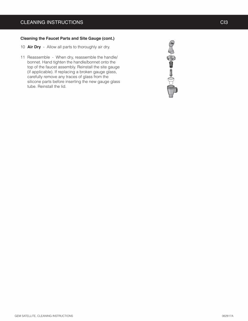
10 Air Dry - Allow all parts to thoroughly air dry.
11 Reassemble - When dry, reassemble the handle/bonnet. Hand tighten the handle/bonnet onto the top of the faucet assembly. Reinstall the site gauge (if applicable). If replacing a broken gauge glass, carefully remove any traces of glass from the silicone parts before inserting the new gauge glass tube. Reinstall the lid.

PROGRAMMING GUIDE PG2
2 Visible only when model selected = GEMX (Twin or Single)
1 Visible only when model selected = Gemini or Gemini-IF (Twin or Single)
Factory default is Gemini® Twin - One Batch
Label style may vary
* “Ready” on some models
With unit OFF, press and hold bottom right BREW button (4). Then press and release ON/OFF button (2). Continue to hold down BREW button until Enter Code appears.
Enter 4 digit code. (factory default = 1-2-3-4)
To enter programming mode:
1
2
1,2
1,2
*
IMPORTANT: All programming functions are performed with the three center buttons.
The symbols below the buttons are:
Scroll LEFT/UP (1)
SELECT or ENTER to save new parameter (2)
Scroll RIGHT/DOWN (3)
Once you enter programming mode, press or to scroll LEFT or RIGHT to the various menus (Global Recipes, Non Brew Prog, Brew Button Prog, etc.). Press (SELECT) to enter a menu. Then press or to scroll UP or DOWN through a menu. When the desired menu item appears on the screen, press (SELECT) to access. See Programming Options for detailed descriptions.

Programming Options
Some menus save and exit automatically when a parameter is updated. Other menus exit to the previous menu when a parameter is saved. To exit, press until EXIT appears on the display, then press .
Global Recipes Menu
Select from the following coffee types: Gourmet STD (standard), Light Roast, Dark Roast, High Yield, Filter Pack or Decaf. The factory default setting is Gourmet STD. Selecting the coffee type sets the various brew settings for the brewer, shown below and on the following pages, to the factory recommended settings for the type of coffee being brewed. If desired, the individual brew settings may be changed once the coffee type is selected to meet your brewing needs.
IMPORTANT: If you change any of the brewer settings on the following pages, some or all of them
Non-Brew Programming Menu
Temperature - or to choose the desired temperature. Then press
to set and exit.
Energy Save Mode - saves energy during periods when the brewer is not in use (the factory default is OFF). When set to ON, the brewer automatically shuts off four hours (two hours on older units) after the last brew
four hours (two hours on older units) after the last brew cycle. Press the ON/OFF button to return to normal
non-use. Once accessed, press or to choose the desired setting. Then press to set and exit.
Brew Count Odom - When accessed, this feature displays the total brew cycles since the odometer was last reset. Press to exit or reset and exit.
Quality Timer - INTELLIFRESH® FEATURES section for a complete description of how the timer operates. Once accessed, press or to choose the desired setting. Then press to set and exit.
Brew Count Total - when accessed, displays the total brew cycles on the brewer. It cannot be reset. The display returns to the previous screen automatically after a few seconds.
Cold Brew Lock - adjusts the temperature at which the brewer will brew coffee when the BREW button is pressed (Ready to Brewtemperature at which the heating element turns on to reheat the water in the tank. The available settings
or to choose the desired setting. Then press to set and exit.
Master Reset - resets the brewer universal control module (UCM) to the factory default settings. Once accessed, “Are You Sure?” will appear on the display. Press for Yes or for No.
IMPORTANT: If you reset the UCM to the factory defaults, you MUST reprogram the Model Select and number of batches to match the number on the model number label and the label on the UCM for proper operation.
PROGRAMMING GUIDE PG2

PROGRAMMING GUIDE PG2
Programming Options (cont.)
Service Call - sets the service phone number that appears on the display when the UCM detects a SENSOR ERROR or WATER ERROR . Once accessed, press or to choose the number to be changed. Then press
repeatedly to change the number value. Press or to choose the next number to change or choose exit and press .
Access Code - sets the access code entered to access programming mode (the factory default is 1-2-3-4). Once accessed, press or to choose the number to change. Then press repeatedly to change the number value (range is 1 to 4). Press or to choose the next number to change or choose exit and press .
Banner Name - changes the banner name that appears on the display (the factory default is Curtis). No banner name appears when all blanks are entered. Once accessed, press or to choose the letter to change. Then press repeatedly to change the number value. Press or to choose the next number to change or choose ex and press to exit.
Warmer Auto-Off - (some models) adjusts the length of time that elapses before the satellite warmer shuts off
default is “disabled”). The range is 1 to 12 hours. Once accessed, press or to adjust the number of hours. Then press to set and exit.
P-Maintenance - turns on/off and adjusts the P-Maintenance (preventive maintenance) brew monitor (the factory default is OFF). When ON, the UCM measures the number of gallons brewed before the
or to choose the desired setting, then, press to exit.
Beeper On/Off - turns the beeper that is heard each time a button is pressed on or off (the factory default is ON). Once accessed, press or to choose the desired setting. Then, press to exit.
Drip-out Mode - to drain from the brew basket before the brew basket lock releases (the factory default is 2 min.). This feature
accessed, press or to choose desired setting, then, press to exit.
Warmers Default - (some models) sets the warmer temperature (the factory default is MED). The available
accessed, press or to choose the desired setting, then press . On twin brewers press or to choose the desired setting for the second warmer, then press . Press to exit. *OFF option not available on GEMX
Display Brew Time - turns the display of the brew time during brewing on or off (the factory default is ON). Once accessed, press or to choose the desired setting, then press to exit.
Display Messages - turns display of the message “Rinse Server Before Brewing” ON or OFF (the factory default is ON). Once accessed, press or to choose the desired setting, then press to exit.
[QT] Display Timers [On/Off] - (some models, QT Alarm must be on) turns the quality timer countdown display ON or OFF (the factory default is OFF). Once accessed, press or to choose the desired setting. Then, press to exit.
QT Alarm On/Off - (some models) turns the quality timer alarm ON or OFF (the factory default is ON for Gemini models, OFF for GEMIF and GEMX). An audible alarm goes off when the quality timer has expired. Once accessed, press or to choose the desired setting. Then, press to exit.

Programming Options (cont.)
Satellite Color - (GEMX series models only) changes the color scheme of the quality timer LEDs. Once accessed, press or to choose the desired color to indicate “fresh” (ON). Press to save, then press
or to choose the desired color to indicate “expired”. Press to save and exit.
Brew Button Programming Menu
until Exit appears on the display. Press to exit, then re-enter the Brew Button Program to program the next one.
Brew by Volume - MEDIUM
desired volume is reached, press the same BREW button again to stop the brew cycle and set the volume.
Brew by Time - adjusts the amount of coffee brewed by time rather than by volume (the factory defaults are or until the
repeatedly to change the number value. Press or until the repeatedly to change the number value. Press or until “ex”
to exit.
Pre-Infusion - sets the brewer Pre-Infusion time (Pulse Brew must be off to access, the factory default is
seconds. Once accessed, press or to choose the desired setting, then, press to exit. To turn off pulse
When Pre-infusion is ON, Pulse Brew disappears from the list of menu items.
Pulse Brew - selects the pulse brew pattern (Pre-Infusion must be off to access, the factory default is C). The or to
choose the desired setting. Then, press to exit.
disappear from the list of program selections.
Pulse Brew Guidelines
• Filter pack type coffees typically extract better with the A and B pulse setting. • Decaffeinated coffees typically extract better with the B pulse setting. • High-yield coffees typically extract better with the C pulse setting. Of course, any of the A, B or C
• Settings D and E are manual pulse counts.
PROGRAMMING GUIDE PG2
Setting Description
A Toward the beginning of brew cycle: 4 cycles of 10 seconds on and 10 seconds off, then on until end of brew cycle.
BStarts towards ends of brew cycle. 4 cycles of 10 seconds off and 4 cycles of 10 seconds on. Ends when brew cycle ends.
C Starts at beginning of brew cycle. 5 cycles of 25 seconds on and 20 seconds off, then on until end of brew cycle.
DManually set. Starts at beginning of brew cycle. Number of pulses is adjustable from 1 to 20. Pulse on time and off time are both adjustable from 5 to 150 seconds.
EManually set. Starts at beginning of brew cycle. Number of pulses is adjustable from 1 to 8. Pulse on time and off time are both adjustable from 1 to 150 seconds.
PROGRAMMING GUIDE PG2
Programming Options (cont.)
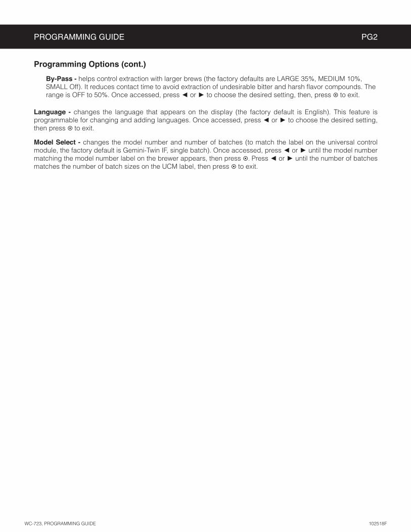
By-Pass -
or to choose the desired setting, then, press to exit.
Language - changes the language that appears on the display (the factory default is English). This feature is programmable for changing and adding languages. Once accessed, press or to choose the desired setting, then press to exit.
Model Select - changes the model number and number of batches (to match the label on the universal control module, the factory default is Gemini-Twin IF, single batch). Once accessed, press or until the model number matching the model number label on the brewer appears, then press . Press or until the number of batches
to exit.

ROUGH-IN DRAWINGS RD2
GEMTIF - Twin Coffee Brewer
GEMSIF - Single Coffee Brewer
GEMSIF/GEMTIF, ROUGH-IN DRAWING 011718D
30.83 in [78.3 cm]
5.52 in [14.0 cm]
12.78 in [32.5 cm]7.82 in
[19.9 cm]
11.99 in [30.5 cm]
22.39 in [56.9 cm]
4.00 in [10.2 cm]
18.11 in [46.0 cm]
0.90 in [2.3 cm]
5.48 in [13.9 cm]
7.82 in [19.9 cm]
12.78 in [32.5 cm]
30.58 in [77.7 cm]
0.87 in [2.2 cm]
11.96 in [30.4 cm]
4.00 in [10.2 cm]
22.39 in [56.9 cm]
9.11in [23.1 cm]

ROUGH-IN DRAWINGS RD75
GEM3IF - Satellite Server
GEM3IF, ROUGH-IN DRAWING 062317NC
13.48 in [34.2 cm]
10.28 in [26.1 cm]
9.98 in [25.3 cm]
11.72 in [29.8 cm]
11.48 in [29.2 cm]
0.27 in [0.7 cm]
8.94 in [22.7 cm]
8.94 in [22.7 cm]

27
ILLUSTRATED PARTS LIST IP2
GEMSIF/GEMTIF - GENERIC, ILLUSTRATED PARTS/RECOMMENDED PARTS 042518E
1110
12
1529
18
36
24
25
34
16
3028
GEMTIF - Main Chassis - Exploded View
A
Water tank assembly, see section IP26
5A5B
2631
23A23B
19A19B
41
40
40
40
20A20B
39
22A22B38A
38B
9
17
21
2A2B
3A3B
43
4A4B37A37B8A427A
7B
33A33B
6A6B
35A35B
14
13A13B
40
40
8A8B8C
1

ITEM # PART # DESCRIPTION
1 GEM3IFSATELLITE SERVER, 1-1/2 GAL. 75W 120V .60A W/INTELLIFRESH
2A* WC-821WDR 1,2 VALVE, DUMP LEFT 120V 12W W/INTERNAL RESISTOR & DIODE
2B WC-853 3VALVE, BREW DUMP LEFT 240V 12W GEM12D/TP/TPC
3A WC-442 1,2 SOLENOID, LOCK BREW CONE RIGHT/LEFT 120V TP2T/TP2S/GEMSS/GEM
3B WC-446 3SOLENOID, LOCK BREW CONE RIGHT 220V THERMOPRO/GEMTS
4A* WC-2977K a KIT, SPRAYHEAD FITTING METAL
4B WC-2977-101K b KIT, SPRAYHEAD FITTING PLASTIC
5A* WC-844-101 1,2 VALVE, BY-PASS, NON-ADJUSTABLE WITH RESTRICTOR (WC-2945)
5B WC-844-102 3VALVE, BY-PASS, 220V NON-ADJUSTABLE W/ RESTRICTOR (WC-2945)
6A WC-37132KIT, VALVE REPAIR FOR INVENSYS WC-820WDR,WC-821WDR, WC-844WDR (OLDER UNITS)
6B WC-37132-101KIT, VALVE REPAIR FOR DELTROL WC-820WDR,WC-821WDR, WC-844WDR (NEWER UNITS)
7A WC-723 1,2 CONTROL MODULE, UCM 120V TP2S /TP2T GEMSS/GEMTS
7B WC-728 3CONTROL MODULE, UCM 220V TP2S/ TP2T/GEMSS/GEMTS
8A* WC-39744LABEL, UCM OVERLAY DUAL TWIN 3-BATCH GEMTIF
8B* WC-39756LABEL, UCM OVERLAY PANEL 2-BATCH GEMTIF CURTIS
8C* WC-39755LABEL, UCM OVERLAY PANEL 1-BATCH GEMTIF CURTIS
9* WC-29050 SPRAYHEAD, AMBER ADVANCED FLOW
10* WC-8559RELAY, SOLID STATE 280V/40A W/ HEATSINK AND QUICK DISCONNECTS
11* WC-3417BREW CONE,ASSY W/SPLASH POCKET BRWN STYLIZED GEMIN HOT COFFEE
12 WC-39745 LABEL, BOTTOM PANEL GEMTIF
13A WC-61959 1,3 COVER, FRONT GEMTIFSS
13B WC-61959-BLK 2 COVER, FRONT GEMTIFBLK
14 WC-61963 PLATE, HOLDER IF CONNECTORS GEMTIF
15 WC-38504LABEL, WARNING SHOCK HAZARD INTELLI-FRESH
16 WC-61961 DECK, WARMER GEMTIFSS NEW
17 WC-29044-101 SLEEVE, OVERFLOW
18* WC-2402P-P ELBOW, 3/8"FL x 3/8" NPT PLATED
19A* WC-847 1,2 VALVE, INLET 2 GPM 120V 10W GEN USE BROWN BODY
19B WC-883 3 VALVE, INLET 2 GPM 240V 6W
ITEM # PART # DESCRIPTION
20A* WC-820WDR 1,2 VALVE, DUMP RIGHT 120V 12W W/INTERNAL RESISTOR & DIODE
20B WC-854 3VALVE, BREW DUMP RIGHT 240V 12W GEM12D/TP/TPC
21* WC-1501 FUSE, HOLDER ASSY W/5A FUSE
22A* WC-102 1,2 SWITCH, TOGGLE NON-LIT SPST 15A 125/6A 250VAC RESISTIVE
22B WC-103 3SWITCH, TOGGLE NON-LIT DPST 25A 125/250VAC RESISTIVE
23A WC-61955 1,3 COVER, TOP SSTL GEMTIF
23B WC-61955-BLK 2 COVER, TOP GEMTIF BLK
24* WC-3528LEG, 4” ADJUSTABLE 3/8-16 THRD ITALIAN STYLE
25* WC-1809FAUCET, PS/HPS SERIES HOT WTR 1/2-20 UNF AP/ALP
26* WC-5310 TUBE, 5/16 ID x 1/8W SILICONE GEN USE
27* WC-5231 COMPOUND, HEAT SINK 5OZ
28 WC-571K-R KIT, IF CONNECTOR- RIGHT
29 WC-571K-L KIT, IF CONNECTOR- LEFT
30 WC-43133O-RING, 1.424ID X 1.630 OD X .103 WALL GEMIF’s
31* WC-5350 TUBE, 1/2 ID x 1/8W SILICONE GEN USE
32 WC-1250 3CORD, 4mm² 90ºC 49A 450/750V 6 FT LG W/FERRULES ONE END (NOT SHOWN)
33A WC-13335 1,2HARNESS ASSY, COMPLETE TP2T10/ GEMTS FOR SOLID STATE RELAY (INCLUDES TERMINAL BLOCK)
33B WC-13338 3HARNESS ASSY, COMPLETE TP2T30 GEMTS FOR SOLID STATE RELAY (INCLUDES TERMINAL BLOCK)
34 WC-596K 3 KIT, NOISE FILTER EMI 250V/30A 1PH
35A WC-61954 1,3 PLATE, BREW CONE STOP SSTL GEMTIF
35B WC-61954-BLK 2 PLATE, BREW CONE STOP GEMTIF BLK
36 WC-1412 CORD GRIP, 3/4” FOR METAL CORD TO .81”OD
37A WC-4320 aO’RING, 0.487I.D.x 0.693OD x0.103CS BUNA-N #112
37B WC-43089 bGASKET, 1.00OD X .625 I.D. X .030 THK WHITE EPDM 70 SHORE
38A WC-4213-P a NUT, 5/8 LOCK PLATED
38B WC-4212-02 b NUT, 5/8-18 JAM PLASTIC
39 WC-314 POWER BLOCK, 5 STATION
40 WC-4426 SCREW, 8-32x3/8 PH HEAD TRUSS
41 WC-4616SCREW, 1/4-20 x 1/2 PHILLIPS PAN HEAD STAINLESS STEEL
42 WC-4439 SCREW, 6-32x¼ PHIL PAN HD SS
43 WC-4412 SCREW, 10-32x3/16” PH PN HD MS SS
GEMTIF - Main Chassis - Parts List
ILLUSTRATED PARTS LIST IP2
1 GEMTIF10A1000, 2 GEMTIF10B1000, 3 GEMTIF30A1000
a
older units.
b Units built before 05/15/17.
GEMSIF/GEMTIF - GENERIC, ILLUSTRATED PARTS/RECOMMENDED PARTS 042518E

ILLUSTRATED PARTS/RECOMMENDED PARTS IP2
GEMSIF/GEMTIF - GENERIC, ILLUSTRATED PARTS/RECOMMENDED PARTS 042518E
Supplies and Accessories - All Models
CAB-1 - Cleaning BrushWC-29050 - Spray HeadSold individually or by the case
1
5
12142726
15
24
10
13
16
3217
20
30
33
A
GEMSIF - Main Chassis - Exploded View
Water tanks assemblies: Single voltage units, see section IP31 Dual voltage units, see section IP32
4A4B
2A2B
3A3B
39
39
39
38
3939
29A29B
2334
18
7A7B
19A19B
35A35B
21A21B
31A31B31C
25
28
36A36B
37A37B
40
41
229A9B9C
8A8B
11A11B
6A6B

ILLUSTRATED PARTS LIST IP2
GEMSIF/GEMTIF - GENERIC, ILLUSTRATED PARTS/RECOMMENDED PARTS 042518E
ITEM # PART # DESCRIPTION
1 GEM3IFSATELLITE SERVER, 1-1/2 GAL. 75W 120V .60A W/INTELLIFRESH
2A WC-61928 1,2,4 COVER, TOP ALPGT/D500GT/D60GT/TLP/TCTS/CBS/GEMSS
2B WC-61928-BLK 3 COVER, TOP GEMSIF63B1000
3A* WC-820WDR 1,2,3 VALVE, DUMP RIGHT 120V 12W W/INTERNAL RESISTOR & DIODE
3B WC-854 4VALVE, BREW DUMP RIGHT 240V 12W GEM12D/TP/TPC
4A* WC-2977K a KIT, SPRAYHEAD FITTING METAL
4B WC-2977-101K b KIT, SPRAYHEAD FITTING PLASTIC
5 WC-3417BREW CONE,ASSY W/SPLASH POCKET BRWN STYLIZED GEMIN HOT COFFEE
6A WC-442 1,2,3 SOLENOID, LOCK BREW CONE RIGHT/LEFT 120V TP2T/TP2S/GEMSS/GEM
6B WC-446 4SOLENOID, LOCK BREW CONE RIGHT 220V THERMOPRO/GEMTS
7A* WC-844-101 1,2,3 VALVE, BY-PASS, NON-ADJUSTABLE WITH RESTRICTOR (WC-2945)
7B WC-844-102 4VALVE, BY-PASS, 220V NON-ADJUSTABLE W/ RESTRICTOR (WC-2945)
8A WC-723 1,2,3 CONTROL MODULE, UCM 120V TP2S /TP2T GEMSS/GEMTS
8B WC-728 4CONTROL MODULE, UCM 220V TP2S/ TP2T/GEMSS/GEMTS
9A* WC-39801LABEL, UCM PANEL 3-BATCH GEMSIF INTELLIFRESH CURTIS
9B* WC-39802LABEL, UCM PANEL 2-BATCH GEMSIF INTELLIFRESH CURTIS
9C* WC-39803LABEL, UCM PANEL 1-BATCH GEMSIF INTELLIFRESH CURTIS
10* WC-8559RELAY, SOLID STATE 280V/40A W/ HEATSINK AND QUICK DISCONNECTS
11A WC-61927 1,2,4 COVER, FRONT GEMSIF10/63/30
11B WC-61927-BLK 3 COVER, FRONT GEMSIF63B1000
12 WC-39800LABEL, BOTTOM WRAP GEMSIF INTELLIFRESH CURTIS
13* WC-1809FAUCET, PS/HPS SERIES HOT WTR 1/2-20 UNF AP/ALP
14 WC-61963 PLATE, HOLDER IF CONNECTORS GEMTIF
15* WC-3528LEG, 4" ADJUSTABLE 3/8-16 THRD ITALIAN STYLE
16 WC-61930 DECK, WARMER W/A GEMSIF63B1000
17* WC-2402P-P ELBOW, 3/8”FL x 3/8” NPT PLATED
18 WC-1501 FUSE, HOLDER ASSY W/5A FUSE
19A WC-59020 1,2,4 PANEL, BOTTOM BACK REMOVABLE
19B WC-59020-BLK 3PANEL, BACK REMOVABLE GEMSS BLACK TEXTURE
ITEM # PART # DESCRIPTION
20* WC-103SWITCH, TOGGLE NON-LIT DPST 25A 125/250VAC RESISTIVE
21A* WC-847 1,2,3 VALVE, INLET 2 GPM 120V 10W GEN USE BROWN BODY
21B WC-883 4 VALVE, INLET 2 GPM 240V 6W
22* WC-29050 SPRAYHEAD, AMBER ADVANCED FLOW
23* WC-5310 TUBE, 5/16 ID x 1/8W SILICONE
24* WC-5231 COMPOUND, HEAT SINK 5OZ
25* WC-314 POWER BLOCK, 5 STATION
26 WC-38504LABEL, WARNING SHOCK HAZARD INTELLI-FRESH
27 WC-43133O-RING, 1.424ID X 1.630 OD X .103 WALL GEMIF’s
28 WC-29044-101 SLEEVE, OVERFLOW
29A* WC-37132KIT, VALVE REPAIR FOR INVENSYS WC-820WDR,WC-821WDR, WC-844WDR (OLDER UNITS)
29B WC-37132-101KIT, VALVE REPAIR FOR DELTROL WC-820WDR,WC-821WDR, WC-844WDR (NEWER UNITS)
30 WC-596K 4 KIT, NOISE FILTER EMI 250V/30A 1PH
31A WC-13287 1,2,3 HARNESS, ASSY COMPLETE GEMSS (INCLUDES TERMINAL BLOCK)
31B WC-13298 2HARNESS ASSY, DV CONVERSION GEMSS/TP2S
31C WC-13379 4HARNESS, ASSY COMPLETE GEMSS EXPORT GEMSS30 (INCLUDES TERMINAL BLOCK)
32 WC-1412 CORD GRIP, 3/4” FOR METAL CORD TO .81”OD
33 WC-571K-R KIT, IF CONNECTOR- RIGHT
34 WC-5350 TUBE, 1/2 ID x 1/8W SILICONE GEN USE
35A WC-1200 2 CORD, 14/3 SJTO 6’ BLK W/PLUG
35B WC-1250 4CORD, 4mm² 90ºC 49A 450/750V 6 FT LG W/FERRULES ONE END
36A WC-4320 aO’RING, 0.487I.D.x 0.693OD x0.103CS BUNA-N #112
36B WC-43089 bGASKET, 1.00OD X .625 I.D. X .030 THK WHITE EPDM 70 SHORE
37A WC-4213-P a NUT, 5/8 LOCK PLATED
37B WC-4212-02 b NUT, 5/8-18 JAM PLASTIC
38 WC-4426 SCREW, 8-32x3/8 PH HEAD TRUSS
39 WC-4616SCREW, 1/4-20 x 1/2 PHILLIPS PAN HEAD STAINLESS STEEL
40 WC-4439 SCREW, 6-32x¼ PHIL PAN HD SS
41 WC-4412 SCREW, 10-32x3/16” PH PN HD MS SS
GEMSIF - Main Chassis - Parts List
1 GEMSIF10A1000, 2 GEMSIF63A1000, 3 GEMSIF10B1000, 4 GEMSIF30A1000
a
older units.
b Units built before 05/15/17.

ILLUSTRATED PARTS/RECOMMENDED PARTS IP26
ITEM # PART # DESCRIPTION
1A WC-54287 TANK, ASSY TPS1T/GEMTS
1B WC-62033 TANK, COMPLETE GEMTS W/ULTEM FITTINGS
2 WC-37008 KIT, TANK LID ROUND (INCLUDES GASKET)
3* WC-37357KIT, STRAIGHT PLASTIC FITTING AND BUSHING 12MM
4A1 WC-5528K KIT, WATER LEVEL PROBE, SILICONE
4B2 WC-5502-01KIT, PROBE, ASSY WATER LEVEL W/HEX FITTING, O-RING & NUT
5* WC-934-04KIT,ELEMENT HEATING 2.5KW 220V W/ JAM NUT & SILICONE WASHERS
6* WC-1438-101 SENSOR, TEMPERATURE TANK
ITEM # PART # DESCRIPTION
7* WC-4382 GUARD, SHOCK HTNG ELMNT DOUBLE
8* WC-522THERMOSTAT, HI LIMIT HEATER CONTROL DPST 277V 40A
9* WC-37365 KIT, FITTING TANK INLET
10* WC-37266 KIT, FITTING TANK OVERFLOW
11* WC-37317 KIT, STRAIGHT FITTING & BUSHNG 8MM GEN USE
12* WC-43055 GUARD, SHOCK RESET THERMOSTAT (WC-522)
13* WC-43067 SILICONE TANK LID O-RING, 4-1/2” I.D. X Ø.285
WC-62033 - Tank Assembly
2
10
4A
311
7
68
12
4B
9
5
9
WC-62033 - Tank Assembly - Parts List
1 Units built 01/04/2019 and later.
2 Units built before 01/04/2019. Replaces WC-5527.
* Recommended parts to stock.
1A1B
13

ILLUSTRATED PARTS LIST IP31
ITEM # PART # DESCRIPTION
1 WC-62035 TANK, COMPLETE GEMSS W/ULTEM FITTINGS
2 WC-5853-102 COVER, TOP HEATING TANK GEN USE
3* WC-43062 GASKET, TANK LID
4A1 WC-5528K KIT, WATER LEVEL PROBE, SILICONE
4B2 WC-5502-01KIT, PROBE, ASSY WATER LEVEL W/HEX FITTING, O-RING & NUT
5* WC-906-04KIT, ELEMENT, HEATING 2KW 220V W/ JAM NUT & SILICONE O-RING
6* WC-1438-101 SENSOR, TEMPERATURE TANK
7* WC-4394GUARD, SHOCK/HEATING ELEMENT FOR SINGLE HEATING ELEMENT
WC-62035 - Tank Assembly - Parts List
ITEM # PART # DESCRIPTION
8* WC-522THERMOSTAT, HI LIMIT HEATER CONTROL DPST 277V 40A
9* WC-43055 GUARD, SHOCK RESET THERMOSTAT (WC-522)
10* WC-37266 KIT, FITTING TANK OVERFLOW
11* WC-37317 KIT, STRAIGHT FITTING & BUSHING 8mm GEN USE
12* WC-37365 KIT, FITTING TANK INLET
13* WC-37357KIT, STRAIGHT PLASTIC FITTING AND BUSHING 12MM
WC-62035 - Tank Assembly
2
3
104A
11
12
6
78
9
1
5
4B
1 Units built 01/04/2019 and later.
2 Units built before 01/04/2019.Replaces WC-5527.
* Recommended parts to stock.
13

ILLUSTRATED PARTS LIST IP32
ITEM # PART # DESCRIPTION
1 WC-62034TANK, COMPLETE GEMSS DV W/ ULTEM FITINGS
2 WC-5853-102 COVER, TOP HEATING TANK GEN USE
3* WC-43062 GASKET, TANK LID
4A1 WC-5528K KIT, WATER LEVEL PROBE, SILICONE
4B2 WC-5502-01KIT, PROBE, ASSY WATER LEVEL W/HEX FIT-TING, O-RING & NUT
5* WC-904-04KIT,ELEMENT, HEATING 1.6KW120V W/ JAM NUT & SILICONE O-RING
6* WC-1438-101 SENSOR, TEMPERATURE TANK
7* WC-4394GUARD, SHOCK/HEATING ELEMENT FOR SIN-GLE HEATING ELEMENT
ITEM # PART # DESCRIPTION
8* WC-522THERMOSTAT, HI LIMIT HEATER CONTROL DPST 277V 40A
9* WC-43055 GUARD, SHOCK RESET THERMOSTAT (WC-522)
10* WC-37266 KIT, FITTING TANK OVERFLOW
11* WC-37317KIT, STRAIGHT FITTING & BUSHNG 8mm GEN USE
12* WC-37365 KIT, FITTING TANK INLET
13* WC-37357KIT, STRAIGHT PLASTIC FITTING AND BUSHING 12MM
WC-62034 - Tank Assembly
2
3
104A
1113
12
6
7
8
9
1
5
WC-62034 - Tank Assembly - Parts List
1 Units built 01/04/2019 and later.
2 Units built before 01/04/2019.Replaces WC-5527.
* Recommended parts to stock.
4B

ELECTRICAL SCHEMATICS ES2
GEMSIF10A1000/GEMSIF10B1000, ELECTRICAL SCHEMATIC 022717A
GEMSIF10A1000, GEMSIF10B1000

GEMSIF63A1000
ELECTRICAL SCHEMATICS ES3
GEMSIF63A1000, ELECTRICAL SCHEMATIC 022717NC

ELECTRICAL SCHEMATICS ES4
1 GRINDER INTERLOCK2 COMMON-SOLID STATE RELAY & GRINDER3 SOLID STATE RELAY +5 Vdc4 BREW CONE LOCK5 NOT USED6 INLET VALVE7 BYPASS VALVE8 NOT USED9 IF WARMER10 NOT USED11 NOT USED12 NOT USED13 TANK TEMPERATURE SENSOR14 TANK TEMPERATURE SENSOR15 UCM GROUND16 WATER LEVEL PROBE17 220-240V L218 220-240V L119 BREW VALVE20 NOT USED
UCM Pin Assignments20 Pin Connector
GEMSIF30A1000, GEMXSIFT30A1000
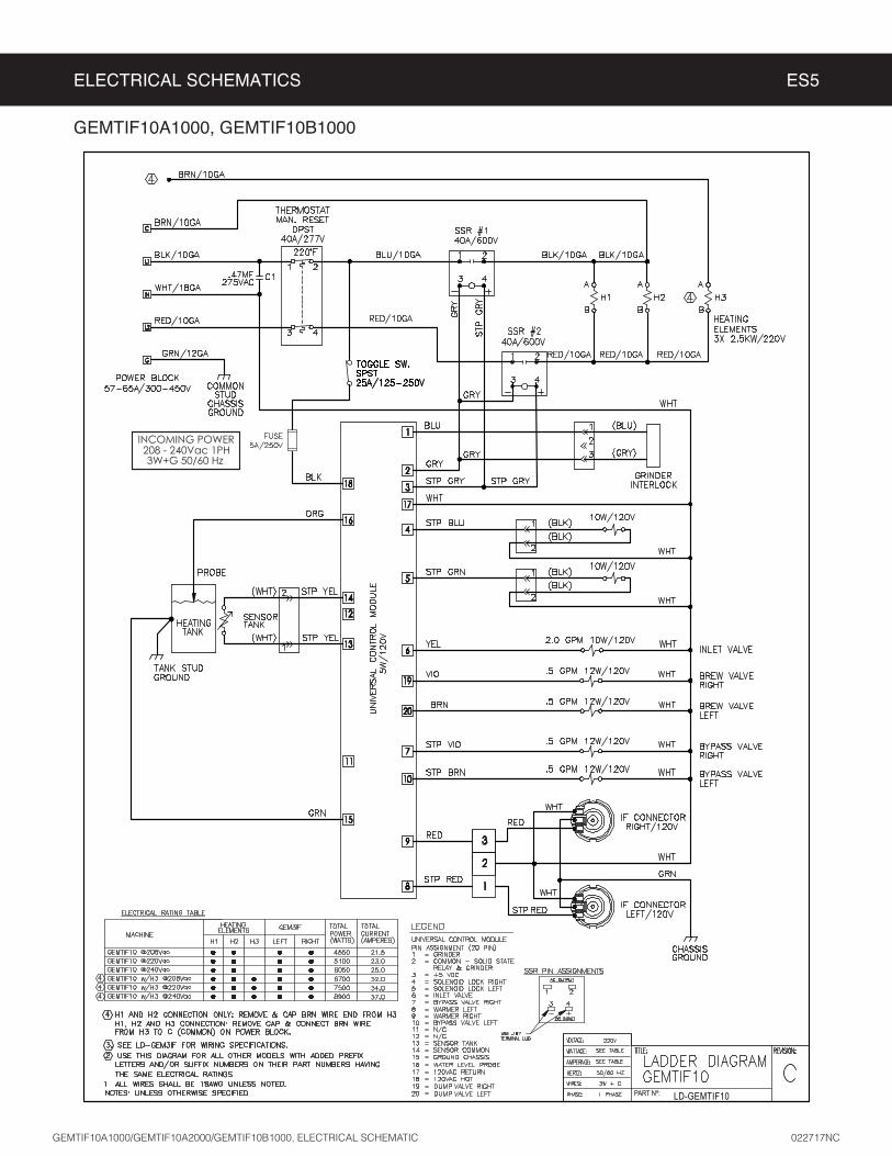
ELECTRICAL SCHEMATICS ES5
GEMTIF10A1000, GEMTIF10B1000

GEMTIF30A1000, GEMXTIFT30A1000
ELECTRICAL SCHEMATICS ES6
LD-GEMTIF-30
1 GRINDER INTERLOCK2 COMMON-SOLID STATE RELAY & GRINDER3 SOLID STATE RELAY +5 Vdc4 BREW CONE LOCK RIGHT5 BREW CONE LOCK LEFT6 INLET VALVE7 BYPASS VALVE RIGHT8 IF WARMER LEFT9 IF WARMER RIGHT10 BYPASS VALVE LEFT11 NOT USED12 NOT USED13 TANK TEMPERATURE SENSOR14 TANK TEMPERATURE SENSOR15 UCM GROUND16 WATER LEVEL PROBE17 220-240V L218 220-240V L119 BREW VALVE RIGHT20 BREW VALVE LEFT
UCM Pin Assignments20 Pin Connector

GEM3IF
ELECTRICAL SCHEMATICS ES29
1 120V HOT2 120V NEUTRAL
3 TANK TEMPERATURE SENSOR
4 TANK TEMPERATURE SENSOR5 HEATER/WARMER OUT
6 HEATER/WARMER OUT
7 LED (+)8 LED (-)
Pin Assignments
ModelVoltage
VAmps
AWa s
WHertz
Hz
# of Conductor
WiresPhase
110 0.55 60 50/60 2 1115 0.58 67 50/60 2 1120 0.60 71 50/60 2 1
GEM3IFx
ELECTRICAL RATING TABLE

GEM3IF-30
ELECTRICAL SCHEMATICS ES30

WARNING:
Electric Shock Hazard -
Scald and Burn Hazard -
Troubleshooting Guidelines
• ERROR CODES•
•
• Use this troubleshooting guide along with the appropriate ELECTRICAL SCHEMATIC.
Valve Test Procedure
in either direction
2
3
Water Not Hot Enough
2 replace the temperature sensor
Water Heats More Slowly Than Usual
2
TROUBLESHOOTING GUIDE TG5
IMPORTANT: always all
Valve Test ProcedureELECTRICAL SCHEMATIC

TROUBLESHOOTING GUIDE TG5
During Brewing
2
3
ELECTRICAL SCHEMATIC
No Power - Display Not Lit
2
3
4
6
Water Tank Does Not Fill
Brewer Does Not Start When Brew Button is Pressed
Brewing
2 Brewing
Sensor Error Message
2
.

2
3
Water Tank Does Not Fill
2
3
4
Coffee/Tea Too Strong
Dispenser Not Filled To Normal Level During Brewing
Dispenser Not Filled To Normal Level During Brewing
2 SPECIFICATIONS
3 sure that the spray head is correctly aligned and that the tubing is routed properly to allow for maximum water
4
ELECTRICAL SCHEMATIC
TROUBLESHOOTING GUIDE TG5
IMPORTANT:
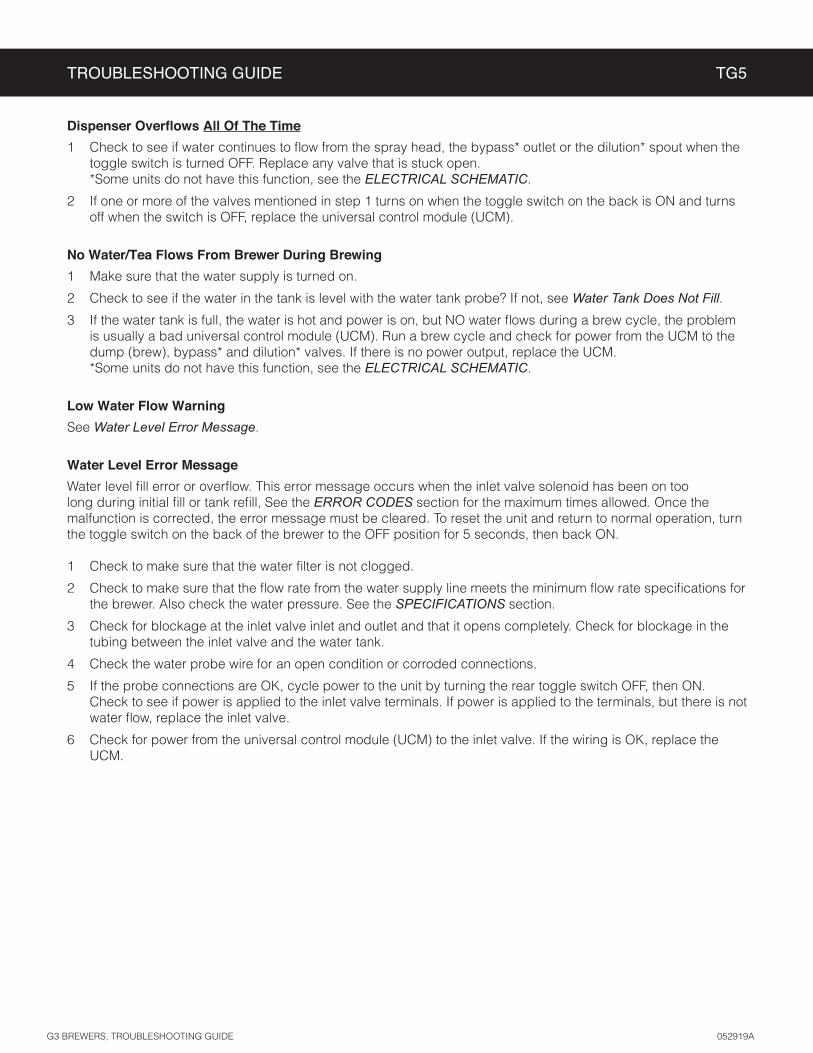
All Of The Time
ELECTRICAL SCHEMATIC
2
No Water/Tea Flows From Brewer During Brewing
2 Water Tank Does Not Fill3
ELECTRICAL SCHEMATIC
Low Water Flow Warning
Water Level Error Message
Water Level Error Message
ERROR CODES
2 SPECIFICATIONS
3
4
6
TROUBLESHOOTING GUIDE TG5

TROUBLESHOOTING GUIDE TG9
Water Does Not Heat At All
• Check to see if the water level in the tank is in contact with the water level probe. If not, see Tank Does Not Fill. The water will not heat unless it is in contact with the probe.
• If the water heats, but is not hot enough, see Water Not Hot Enough.• If Ready to brew appears on the display, but the water is not hot, check the resistance across the leads of the
temperature sensor. If the resistance is less than 10 k and the water is not hot, replace the temperature sensor. If the sensor resistance is above 10 k when the water is cool, replace the universal control module (UCM).
If Heating... appears on the display, but the water is not hot, follow the steps below. The following steps are performed with the rear toggle switch in the ON position.
1 Check for power across the terminals of the heating element(s). If power is being supplied, remove the wires and check for an open heating element.
2 If there is no power to the element(s), trace the circuit back (using the ELECTRICAL SCHEMATIC) to the power
following step. On units having two SSRs, be sure to check both.
3 If there is power into a SSR, but not out, check for 5 Vdc (nominal*) across the + and - pins of the SSR(s). If there is 5 Vdc across the + and - pins of the SSR(s), but no (or low) output voltage at a SSR output terminal, replace the SSR. If 5 Vdc is not being supplied from the UCM, but Heating... appears on the display, check the wiring from the UCM to the SSR(s). If the wiring is OK, replace the UCM.
Water Too Hot (Boiling or Excessive Steaming)
1 If Over Temp Sensor or Ready to Brew appears on the display and the water is too hot, go to Over Temp Sensor Error Message.
2 If the display reads Heatingto the tank and that heat sink compound was used. A properly mounted sensor should have a resistance of around 7 k when the water is hot. If not, replace the sensor.
3 Check to see if the universal control module (UCM) constantly has +5 Vdc output (nominal) to the solid state relay (SSR), regardless of the resistance of the temperature sensor. If so, the UCM is probably bad.
4 If the UCM is working properly, check for a shorted SSR.
Over Temp Sensor Error Message
This error message indicates that the universal control module (UCM) has detected a water overheating problem. The UCM is reading a water temperature in the tank above 210ºF. If the water temperature is too hot, but Heating... appears on the display, see Water Too Hot. Once the malfunction causing the error is corrected, the error message must be cleared. To reset the brewer and return to normal operation, turn the toggle switch on the back of the brewer to the OFF position for 5 seconds, then back on.
1 Check for 5 Vdc (nominal) across the + and - pins of the solid state relay (SSRs). If no power is applied to the SSR and the heating elements are always on, replace the SSR. On units having two SSRs, check both.
2 Turn off power to the brewer and allow the water tank to cool. Once cool, turn power back on while monitoring the voltage across the + and - pins of the SSR(s). During normal operation, the voltage should be 5 Vdc, until the water is hot, then drop to below 1 Vdc. The UCM should be replaced if the voltage reads 5 Vdc constantly even though Ready to brew or Over Temp Sensor appears on the display.
3 If the UCM is operating normally, check for a false over-temp error caused by the temperature sensor. Check the resistance across the leads of the temperature sensor. If the resistance is less than 10 k when the water is cool, replace the temperature sensor.
G3 BREWERS WITH SSR, TROUBLESHOOTING GUIDE 120817A
IMPORTANT: Before proceeding, make sure that the control panel temperature is adjusted to compensate for higher elevations. The factory setting is 200°F. Reduce the temperature setting two degrees for every 1000 feet of elevation above 4000 feet.

TROUBLESHOOTING GUIDE TG13
Satellite Does Not Heat
NOTEreheat cold coffee.
1
(replace the controller).
2 Check to make sure that the warmer is not turned off. See the PROGRAMMING GUIDE section.
3 Check to see if the IntelliFresh LED on the front of the satellite comes on at the beginning of the brew cycle. If neither the LED nor the warmer come on, then it can be assumed that there is no power to the satellite. Make sure that power is being supplied to the IntelliFresh (IF) connector on the brewer when the BREW
ELECTRICAL SCHEMATIC. If power is present at the connector, check the connector contacts. If power is not present at the IF connector, trace the circuit back to the control module to see if it is supplying power to the IF connector.
4 Check the contacts on the satellite IF connector to make sure that they are making good contact with the connector on the brewer.
5
LED Does Not Light (Warmer OK)
1
2 If the LED is OK, suspect the controller.
INTELLIFRESH SATELLITE, TROUBLESHOOTING GUIDE 092217A

ERROR CODES EC4
ERROR MESSAGE WARNING DESCRIPTION CAUSE
Water Level Error
System Fault Messages
An error message will appear on the screen in the event of a malfunction under the following conditions:
1
2
3
G3 BREWER, ERROR CODES 042017A

PRODUCT WARRANTY PW1
3 years, parts and labor, from original date of purchase on digital control boards21
CONDITIONS & EXCEPTIONS
• Adjustments and cleaning: The resetting of safety thermostats and circuit breakers, programming and temperature adjustments are the responsibility of the equipment owner. The owner is responsible for proper cleaning and regular maintenance of this equipment.
• Replacement of items subject to normal use and wear: This shall include, but is not limited to, spray heads, faucets, light bulbs, shear disks, “O” rings, gaskets, silicone tubing, silicone elbows, canister assemblies, whipper chambers and plates, mixing bowls, agitation assemblies and whipper propellers.
• Improper operation of equipment: The equipment must be used for its designed and intended purpose and function.• Improper installation of equipment: This equipment must be installed by a professional technician and must comply with all local elec-
trical, mechanical and plumbing codes.• Improper voltage: Equipment must be installed at the voltage stated on the serial plate supplied with this equipment.• Improper water supply: • Damaged in transit: Equipment damaged in transit is the responsibility of the freight company and a claim should be made with the carrier. • Abuse or neglect (including failure to periodically clean or remove lime accumulations): The manufacturer is not responsible for
variation in equipment operation due to excessive lime or local water conditions. The equipment must be maintained according to the manufacturer’s recommendations.
Repairs and/or Replacements
Return Merchandise Authorization (RMA):All returned equipment must be properly re-packaged in the
original carton and received by Curtis within 45 days following the issuance of a RMA.NO UNITS OR PARTS WILL BE ACCEPTED WITHOUT A RETURN MERCHANDISE AUTHORIZATION
(RMA). THE RMA NUMBER MUST BE MARKED ON THE CARTON OR SHIPPING LABEL. All warranty claims must be submitted within 60 days of service. Invoices will not be processed or accepted without a RMA number. Any defective parts must be returned in order for warranty invoices to be processed and approved.