Embed Size (px)
Citation preview
www GarrettCom com. . www GarrettCom com. .
Corporate Headquarters
GarrettCom, Inc. 47823 Westinghouse Dr. Fremont, CA 94539 Phone (510) 438-9071 Fax (510) 438-9072 Website: http://www.GarrettCom.com email: [email protected]
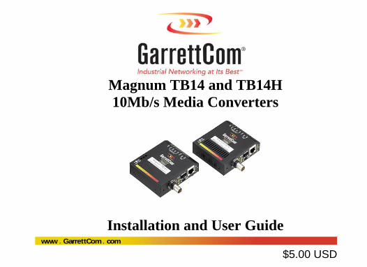
Magnum TB14 and TB14H 10Mb/s Media Converters
Installation and User Guide
$5.00 USD
TB14 and TB14H 10Mb Media Converters Installation and User Guide
i www GarrettCom com. .
Magnum™ TB14 and TB14H 10Mb/s Media Converters Installation and User Guide
Part #: 84-00126Z Rev. D Trademarks GarrettCom is a registered trademark and Magnum, Dymec, DynaStar, Personal Switch, Link-Loss-Learn, S-Ring, Convenient Switch and Converter Switch are trademarks of GarrettCom, Inc.
Ethernet is a trademark of Xerox Corporation
NEBS is a trademark of Telcordia Technologies UL is a registered trademark of Underwriters Laboratories
TB14 and TB14H 10Mb Media Converters Installation and User Guide
ii www GarrettCom com. .
Important: The Magnum TB14 andTB14H 10 Mb/s Media Converters contains no user
serviceable parts. Attempted service by unauthorized personnel shall render all
warranties null and void. If problems are experienced with Magnum TB14/TB14H 10
Mb/s Media Converters products, consult Section 5, Troubleshooting, of this User Guide.
Copyright © 2004 GarrettCom, Inc. All rights reserved. No part of this publication may
be reproduced without prior written permission from GarrettCom, Inc.
Printed in the United States of America.
GarrettCom, Inc. reserves the right to change specifications, performance characteristics
and/or model offerings without notice.
TB14 and TB14H 10Mb Media Converters Installation and User Guide
iii www GarrettCom com. .
Federal Communications Commission
Radio Frequency Interference Statement
This equipment generates, uses and can radiate frequency energy and if not
installed and used properly, that is in strict accordance with the manufacturer's
instructions, may cause interference to radio communication. It has been tested and
found to comply with the limits for a Class A computing device in accordance with the
specifications in Subpart J of Part 15 of FCC rules, which are designed to provide
reasonable protection against such interference when operated in a commercial
environment. Operation of this equipment in a residential area is likely to cause
interference, in which case the user at his own expense will be required to take whatever
measures may be required to correct the interference.
TB14 and TB14H 10Mb Media Converters Installation and User Guide
iv www GarrettCom com. .
Electrical Safety requirements:
1. This product is to be installed Only in Restricted Access Areas (Dedicated Equipment Rooms, Electrical Closets, or the like).
2. 48VDC products shall be installed with a readily accessible disconnect device in the building installation supply circuit to the product.
3. This product shall be provided with a maximum 10A DC Listed fuse or circuit breaker in the supply circuit when connected to a 48V centralized DC source.
4. The external power supply for DC units shall be a Listed, Direct Plug In power unit, marked Class 2, or Listed ITE Power Supply, marked LP, which has suitably rated output voltage (i.e. 24VDC or 48VDC) and suitable rated output current.
5. Product does not contain user replaceable fuses. Any internal fuses can ONLY be replaced by GarrettCom personnel through the RMA process.
TB14 and TB14H 10Mb Media Converters Installation and User Guide
v www GarrettCom com. .
Contacting GarrettCom, Inc
Please use the mailing address, phone and fax numbers and email address listed below:
GarrettCom, Inc. 47823 Westinghouse Dr.
Fremont, CA 94539 Phone (510) 438-9071
Fax (510) 438-9072 Website: http://www.GarrettCom.com
Email: [email protected]
TB14 and TB14H 10Mb Media Converters Installation and User Guide
vi www GarrettCom com. .
TABLE OF CONTENTS Page
1.0 SPECIFICATIONS ............................................................................... 1 1.1 Technical Specifications ...................................................................... 1
2.0 INTRODUCTION ................................................................................. 9 2.1 Inspecting the Package and the Product ............................................... 9 2.2 Product Description ........................................................................... 10 2.3 Features and Benefits ......................................................................... 16 2.4 Applications ....................................................................................... 18
3.0 INSTALLATION ................................................................................. 20 3.1 Locating the Media Converter Unit ................................................... 20 3.2 MC14-TRAY for Rack Mounting Media Converters ........................ 22 3.3 MC14-TR+PS9 & MC14-TR+PS9X2 for Rack Mounting Media Converters .......................................................................................... 23 3.4 DIN-Rail mounting option ................................................................. 26 3.5 Calculating Overall Segment Distance .............................................. 27 3.6 Connecting Ethernet Media ............................................................... 31
TB14 and TB14H 10Mb Media Converters Installation and User Guide
vii www GarrettCom com. .
3.6.1 Connecting Twisted Pair (RJ-45 ports) ...................................... 31 3.6.2 Connecting ThinNet (10BASE2) ............................................... 32
4.0 OPERATION ....................................................................................... 34 4.1 Power Requirements, Power Supply Types for TB14 and TB14H ... 34 4.2 Powering the TB14H (Direct DC) with 12V, 24V or –48V DC ........ 37 4.3 TB14H, DC-powered, -48VDC, 24VDC and 12VDC Installation ... 38 4.4 Dual LEDs, front-panel and side-panel ............................................. 40 4.5 TB14s, BNC Internal Termination Switch......................................... 41 4.6 Up-Link (Cross-over) Switch ............................................................ 42
5.0 TROUBLESHOOTING ...................................................................... 43 5.1 Before Calling for Assistance ............................................................ 44 5.2 When Calling for Assistance ............................................................. 46 5.3 Return Material Authorization (RMA) Procedure ............................. 47 5.4 Shipping and Packaging Information ................................................. 49
APPENDIX A: WARRANTY INFORMATION ......................................... 50
TB14 and TB14H 10Mb Media Converters Installation and User Guide
viii www GarrettCom com. .
Revisions Rev D 10/09: Updated DIN rail mount photo (pg. 26), revised weight specification (pg. 5), added Electrical Safety Requirements (pg. iv) Rev C 09/04: Minor updates on UL Requirements on power supplies Rev C 06/04: Minor updates on Agency approvals and power supplies Rev C 07/03: Minor Update, MK3 units in Series. Rev B 02/03: Minor Update 10/02 for LEDs, corrected 3.6 Connecting Media Rev A 08/02 : Initial release of this user manual, for TB14 and TB14H
TB14 and TB14H 10Mb Media Converters Installation and User Guide
1
www GarrettCom com. .
1.0 SPECIFICATIONS 1.1 Technical Specifications Performance:
Data Rate: 10 Mbps (IEEE 802.3), half duplex mode
Network Standards: Ethernet: IEEE 802.3, 10BASE2, 10BASE-T (Magnum Media Converters are physical layer standard Ethernet products,
and operate independently of all software.)
Number of Media Converters in series:
Experience shows that no more than 3 BNC units can be used in series between repeaters or NICS. For 4 or more in series, noise build-up will typically preclude proper operation. See also Section 3.5, Calculating Segment Distances.
TB14 and TB14H 10Mb Media Converters Installation and User Guide
2
www GarrettCom com. .
Maximum Standard Ethernet Segment Lengths: 10BASE-T (twisted pair): 100 m (328 ft) 10BASE2 ThinNet (BNC): 185 m (607 ft) Note: Magnum Media Converters DO NOT support full length Ethernet segments. See
Section 3.2 of this manual for media lengths and segment distance calculations. Operating Environment: Ambient Temperature: (0ºC to 40ºC) TB14-d, TB14-i (0ºC to 50ºC) TB14-Hd, TB14-Hi (-40ºC to 55ºC) TB14H-Hd, TB14H-Hi (-40ºC to 75ºC) TB14H-12VDC, TB14H-24VDC, TB14H-48VDC Storage Temperature: -40ºC to 85ºC Ambient Relative Humidity: 5% to 95% (non-condensing)
TB14 and TB14H 10Mb Media Converters Installation and User Guide
3
www GarrettCom com. .
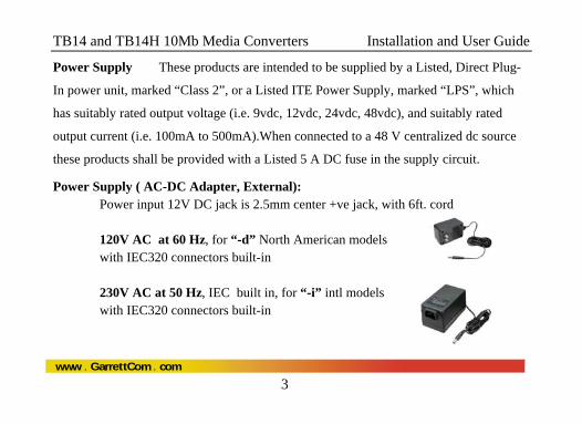
Power Supply These products are intended to be supplied by a Listed, Direct Plug-
In power unit, marked “Class 2”, or a Listed ITE Power Supply, marked “LPS”, which
has suitably rated output voltage (i.e. 9vdc, 12vdc, 24vdc, 48vdc), and suitably rated
output current (i.e. 100mA to 500mA).When connected to a 48 V centralized dc source
these products shall be provided with a Listed 5 A DC fuse in the supply circuit.
Power Supply ( AC-DC Adapter, External): Power input 12V DC jack is 2.5mm center +ve jack, with 6ft. cord 120V AC at 60 Hz, for “-d” North American models with IEC320 connectors built-in
230V AC at 50 Hz, IEC built in, for “-i” intl models with IEC320 connectors built-in
TB14 and TB14H 10Mb Media Converters Installation and User Guide
4
www GarrettCom com. .
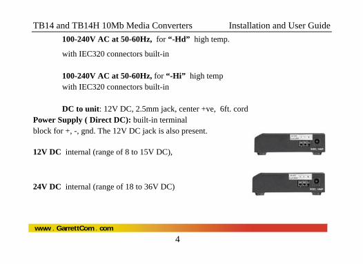
100-240V AC at 50-60Hz, for “-Hd” high temp. with IEC320 connectors built-in
100-240V AC at 50-60Hz, for “-Hi” high temp with IEC320 connectors built-in DC to unit: 12V DC, 2.5mm jack, center +ve, 6ft. cord
Power Supply ( Direct DC): built-in terminal block for +, -, gnd. The 12V DC jack is also present. 12V DC internal (range of 8 to 15V DC),
24V DC internal (range of 18 to 36V DC)
TB14 and TB14H 10Mb Media Converters Installation and User Guide
5
www GarrettCom com. .
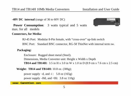
-48V DC internal (range of 36 to 60V DC)
Power Consumption: 3 watts typical and 5 watts max. for all models
Connectors, for Media:
RJ-45 Port: Modular 8-Pin female, with “cross-over” up-link switch BNC Port: Standard BNC connector, RG-58 ThinNet with internal term sw.
Packaging:
Enclosure: Rugged sheet metal (Steel). Dimensions, Media Converter unit: Height x Width x Depth TB14 and TB14H: 3.5 in H x 3.0 in W x 1.0 in D (8.9 cm x 7.6 cm x 2.5 cm)
Weight: TB14 and TB14H: 10.8 oz. (306g);
power supply –d, and -i : 5.8 oz (165g) power supply –Hd, and =Hi: 3.8 oz 110g)
TB14 and TB14H 10Mb Media Converters Installation and User Guide
6
www GarrettCom com. .
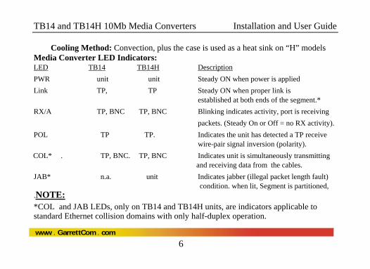
Cooling Method: Convection, plus the case is used as a heat sink on “H” models Media Converter LED Indicators: LED TB14 TB14H Description PWR unit unit Steady ON when power is applied Link TP, TP Steady ON when proper link is established at both ends of the segment.* RX/A TP, BNC TP, BNC Blinking indicates activity, port is receiving packets. (Steady On or Off = no RX activity). POL TP TP. Indicates the unit has detected a TP receive wire-pair signal inversion (polarity).
COL* . TP, BNC. TP, BNC Indicates unit is simultaneously transmitting and receiving data from the cables. JAB* n.a. unit Indicates jabber (illegal packet length fault) condition. when lit, Segment is partitioned, .NOTE: *COL and JAB LEDs, only on TB14 and TB14H units, are indicators applicable to standard Ethernet collision domains with only half-duplex operation.
TB14 and TB14H 10Mb Media Converters Installation and User Guide
7
www GarrettCom com. .
Metal Mounting clips : included DIN-Rail mounting option: Model # DIN-RAIL KIT
Rack-mount option: MC14-TRAY, see http://www.garrettcom.com/mc_tray.htm Agency Approvals:
UL Listed (UL60950), cUL, CE, Emissions meet FCC Part 15, Class A. NEBS L3 and ETSI compliant H model: IEEE P1613 Env. Std. for Electric Power Substations H model: NEMA TS-2 and TEES for traffic control equipment H model: designed for UL2043 above-the-ceiling installation IEC61850 EMC and Operating Conditions Class C for Power Substations Warranty: Three years, return to factory Made in USA
TB14 and TB14H 10Mb Media Converters Installation and User Guide
8
www GarrettCom com. .
1.2 Summary of models and descriptions: TB14-d = TP to BNC, half-duplex, 120V 60Hz AC power supply (office use)
TB14-i = TP to BNC, half-duplex, 230V 50Hz AC power supply (office use)
TB14-Hd = TP to BNC, half-duplex, 100- 240V 50-60Hz AC power supply (Industrial use)
TB14-Hi = TP to BNC, half-duplex, 100- 240V 50-60Hz AC power supply (Industrial use) TB14H-Hd = TP to BNC, half-dpx, 100-240V 50-60Hz, AC power supply (Extended Temperature)
TB14H-Hi = TP to BNC, half-dpx, 100-240V 50-60Hz, AC power supply (Extended Temperature)
TB14H-12V DC = TP to BNC, half-duplex, 12V DC Internal power supply (Extended Temperature)
TB14H-24V DC = TP to BNC, half-duplex, 24V DC Internal power supply (Extended Temperature)
TB14H-48V DC = TP to BNC, half-dpx, -48V DC Internal power supply (Extended Temperature) MC14-TRAY = 19” Rack-mount tray for 14-series Media Converters, up to 16 units
TB14 and TB14H 10Mb Media Converters Installation and User Guide
9
www GarrettCom com. .
2.0 INTRODUCTION This section describes the TB14 and TB14H models, including appearance, features and typical applications.
2.1 Inspecting the Package and the Product Examine the shipping container for obvious damage prior to installing this product; notify the carrier immediately of any damage which you believe occurred during shipment or delivery. Inspect the contents of this package for any signs of damage and ensure that the items listed below are included.
This package should contain:
1 Magnum TB14 or TB14H Media Converter Unit
1 External Power Supply, (except for internal DC power supply models)
1 set Metal mounting clips and screws, 2 each
1 Velcro® Tape section, approximately 3 inches in length
1 User Guide, i.e., this manual (continued next page)
TB14 and TB14H 10Mb Media Converters Installation and User Guide
10
www GarrettCom com. .
Remove the Magnum Media Converter from the shipping container. Be sure to keep the shipping container should you need to ship the unit at a later date.
In the event there are items missing or damaged contact your supplier. If you need to return the unit use the original shipping container. Refer to Section 5 Troubleshooting, for specific return procedures.
2.2 Product Description Rugged packaging, a selection of extended temperature models, choice of AC
and DC power types, ease-of-use features, and energy-efficiency are the primary
characteristics of the Magnum 10Mb TB14 and TB14H Media Converters. All models
offer a graceful way to convert and transmit data between twisted pair and thin coaxial
BNC network cables for media flexibility in new or expanded 10Mb Ethernet networks.
They provide standard collision detection and indication, and comply with the Ethernet
V1.0 / 2.0 specifications and the IEEE 802.3 standards. Power consumed in use is only 3
watts.
TB14 and TB14H 10Mb Media Converters Installation and User Guide
11
www GarrettCom com. .
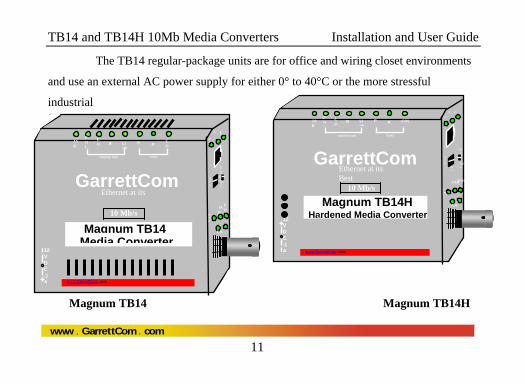
The TB14 regular-package units are for office and wiring closet environments
and use an external AC power supply for either 0° to 40°C or the more stressful
industrial
Magnum TB14 Magnum TB14H
Link
R RPwr
COAX TWISTED PAIR
C
12VDC .1A
UP LIN
A
Magnum TB14Media Converter
JAB
POL
COL
www.GarrettCom .com
10 Mb/s
EXT INT
X =
CA
PWR
JAB
PO
L
CO
GarrettCom Ethernet at its
Link
R RPwr
COAXTWISTED PAIR
CA
Magnum TB14H Hardened Media Converter L
JAB
POL
CO
www.GarrettCom .com
10 Mb/s
EXT INT
UP LIN X
=
CA
PWR
JAB POL
L
COL
GarrettCom Ethernet at its Best
12VDC .1A
TB14 and TB14H 10Mb Media Converters Installation and User Guide
12
www GarrettCom com. .
0° to 50°C ambient temperature. A rugged metal case with convection cooling is
featured. The units can be mounted securely on a closet wall or the side of cabinet, or by
using the metal mounting clips included.
The TB14H Hardened unit features a sealed metal case which is also used as a
heat sink. No air flow is required for cooling, so the TB14H resists dust, dirt, moisture,
smoke and insects, and is plenum rated. Choices of models for external AC or internal
DC power are available. Ambient temperature rating is up to –40°C to +75°C depending
on the power source used. The TB14H is suitable for temperature un-controlled outdoor
applications. Mounting options include panel-mounting, DIN-rail, or rack-mount tray.
The “TB14” series offer a graceful way to convert and transmit data among
twisted pair, and thin coaxial network cabling environments. TB14 Media Converters
cost significantly less than full repeaters and can be used whenever media distance
TB14 and TB14H 10Mb Media Converters Installation and User Guide
13
www GarrettCom com. .
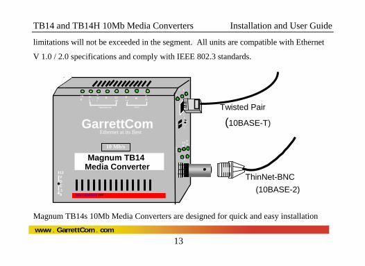
limitations will not be exceeded in the segment. All units are compatible with Ethernet
V 1.0 / 2.0 specifications and comply with IEEE 802.3 standards.
Magnum TB14s 10Mb Media Converters are designed for quick and easy installation
Link
R RPwr
COAX TWISTED PAIR
C
12VDC .1A
UP LIN
A
Magnum TB14 Media Converter
JAB
POL
COL
www.GarrettCom .com
10 Mb/s
EXT INT
X =
CA
PWR
JAB
PO
L
CO
GarrettCom Ethernet at its Best
ThinNet-BNC(10BASE-2)
Twisted Pair
(10BASE-T)
TB14 and TB14H 10Mb Media Converters Installation and User Guide
14
www GarrettCom com. .
even in very tight spaces. Media cables are easily attached to the corresponding Media
Converter. Because of their compact size, Magnum Media Converters can be Velcro®-
mounted on an office wall or the side of a desk or cabinet. Mounting options include
panel-mounting, DIN-rail and rack-mount tray( MC14-TRAY) that neatly holds the units
and associated power supplies is available.
The standard “1-per-unit” external power supply plugs into a nearby AC wall
socket or power strip. The TB14H (Hardened) media converter is also available with
extended temperature power supply AC/DC (External/Internal) to qualify for un-
controlled and Industrial application. Each converter features two full sets of LEDs that
convey essential diagnostic and status information at any angle. See Section 4.1 and 4.4,
for power supply and LED function specifications.
All of the Magnum “TB14s” Media Converters comply with the IEEE 802.3
TB14 and TB14H 10Mb Media Converters Installation and User Guide
15
www GarrettCom com. .
10BASE-T specification for 10 Mb/sec traffic via shielded (STP) or unshielded twisted
pair (UTP) segments. They feature an up-link or cross-over switch to eliminate the need
for a special cross-over cable when connecting to a hub or concentrator and also an
( ∝ - 50Ω ) internal termination switch to control the BNC port by eliminating the TEE –
Connector. The BNC connector complies with IEEE 802.3 10BASE2 specifications.
Note: experience shows that the maximum number of 10Mb Media Converters that can be used in series is three. The cumulative signal noise from 4 or more units together in series may cause packet alignment errors.
TB14 and TB14H 10Mb Media Converters Installation and User Guide
16
www GarrettCom com. .
2.3 Features and Benefits
Reduces Network Costs
Magnum Media Converters offer the ideal solution to efficiently and inexpensively connect Twisted Pair with ThinNet media within an expanding Ethernet network where full repeaters are not required.
No added Repeater Hop Count
Media Converters do not add signal timing delays associated with full repeaters, and can be installed without increasing the repeater hop count of an existing network.
Two sets of LEDs for viewing status from any angle. Each TB14 Media Converter is equipped with a two sets (front and side) of LEDs to provide status information when viewed at any angle or mounting arrangement, rack-mount (MC14- Tray) or wall-mount.
TB14 and TB14H 10Mb Media Converters Installation and User Guide
17
www GarrettCom com. .
Rugged metal case, industrial grade
TB14s Media Converters have a robust design and are packaged in a
rugged sheet metal enclosures to ensure high reliability and durability
even when placed in extended temp; e.g industrial or outdoor applications.
AC and DC Power Supplies with extended temperature ratings
TB14H Media Converters are designed for use in temperature un-
controlled applications, and are available with variety of ratings, external
AC and internal DC power supplies. See Specs, Section 1.1 for details.
Compact design, mount anywhere
Featuring a compact steel case with an external AC power supply,
Magnum TB14 Media Converters can be installed in minimal space in
rack mount cabinets like MC14-TRAY, on table-tops or wall-mounted.
TB14 and TB14H 10Mb Media Converters Installation and User Guide
18
www GarrettCom com. .
2.4 Applications The primary function of a 10Mb Ethernet Media Converter is to permit two different 10Mb media types to coexist inexpensively within the same network by allowing data to be transmitted and received between different media types.
Magnum “TB14s” Media Converters are typically used where new 10BASE-T networking equipment is being installed and connected to existing BNC Ethernet cabling. Magnum “TB14” Media Converters have an external AC power supply and internal DC Power supply, enabling them to be used to convert signals among media that does not have a power source as part of the cabling system, such as twisted pair and BNC. The wide variety of options of AC and DC power supply qualify the TB14 s for use in office locations as well as industrial and even outdoor applications.
In this application, in a Industrial environment where extended temp. supported units is a requirement, the existing BNC network needs to connect with RJ-45 ports in a hub / switch to expand the existing application. The rugged Magnum TB14s with various
TB14 and TB14H 10Mb Media Converters Installation and User Guide
19
www GarrettCom com. .
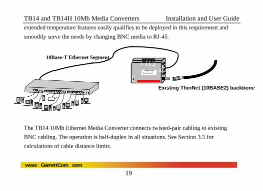
extended temperature features easily qualifies to be deployed in this requirement and smoothly serve the needs by changing BNC media to RJ-45.
The TB14 10Mb Ethernet Media Converter connects twisted-pair cabling to existing BNC cabling. The operation is half-duplex in all situations. See Section 3.5 for calculations of cable distance limits.
Existing ThinNet (10BASE2) backbone
1 2 3 4 5 6 7 8 9 10 11 12 13 14 15 16 17 18 19 20 21 22 23 24
Magnum TB14
Media Converter
T
R
9VDC .3
UP
Link
RX/A
RX\A
Link
Pwr
FIBERTWISTED
LikRX\A
Lik
AC
10Base-T Ethernet Segment
TB14 and TB14H 10Mb Media Converters Installation and User Guide
20
www GarrettCom com. .
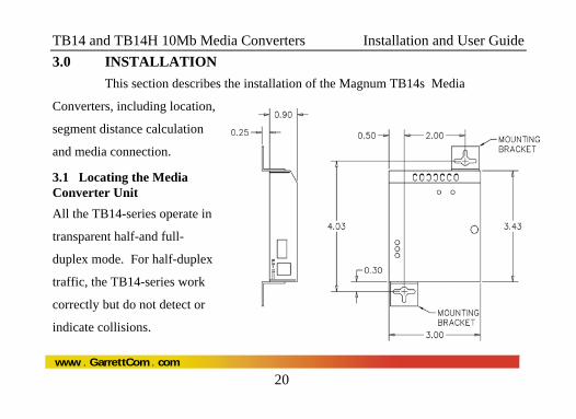
3.0 INSTALLATION This section describes the installation of the Magnum TB14s Media
Converters, including location,
segment distance calculation
and media connection.
3.1 Locating the Media Converter Unit All the TB14-series operate in
transparent half-and full-
duplex mode. For half-duplex
traffic, the TB14-series work
correctly but do not detect or
indicate collisions.
TB14 and TB14H 10Mb Media Converters Installation and User Guide
21
www GarrettCom com. .
The compact and lightweight design of the Magnum Media Converter allows it to be
easily installed in almost any location. A Velcro strip is included for mounting the unit
on a vertical surface such as a wall or cabinet, or for securing the unit on a table-top or
shelf. Alternatively, metal mounting clips and screws are included for a rugged and
secure mounting in any orientation.
Installation of the Magnum TB14 and TB14H Media Converters is a simple procedure.
The installation location is dependent upon the physical layout of the Ethernet network
and associated cabling. Make sure the unit is installed in a location that is easily
accessible to an AC power outlet or power strip, and where convection cooling is not
inhibited. The green Power (PWR) Led must turn ON, when power is applied through the
internal DC input 12V, 24V or –48V DC or external AC through 12V DC jack.
TB14 and TB14H 10Mb Media Converters Installation and User Guide
22
www GarrettCom com. .
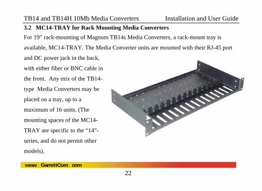
3.2 MC14-TRAY for Rack Mounting Media Converters For 19” rack-mounting of Magnum TB14s Media Converters, a rack-mount tray is
available, MC14-TRAY. The Media Converter units are mounted with their RJ-45 port
and DC power jack in the back,
with either fiber or BNC cable in
the front. Any mix of the TB14-
type Media Converters may be
placed on a tray, up to a
maximum of 16 units. (The
mounting spaces of the MC14-
TRAY are specific to the “14”-
series, and do not permit other
models).
TB14 and TB14H 10Mb Media Converters Installation and User Guide
23
www GarrettCom com. .
A typical installation of the model MC14-TRAY, 19” rack-mount tray will hold a few
(often three to eight) 14-series Media Converters, with their power supplies plugged into
power strips (not included) in the rear area of the tray. Metal mounting screws in the
bottom-front hold the Media Converters firmly in place. The beveled-top edge of the
units permits the LEDs of each unit to be viewed for operational status, even when the
units are very close together.
3.3 MC14-TR+PS9 & MC14-TR+PS9X2 for Rack Mounting Media Converters The MC14-TR+ PS9 and MC14-TR+PS9X2 are another option available for
Rack Mounting the mix-match of 10Mbps and 100Mbps Media Converters together in
19” rack-mount tray. These models comes with built-in common universal AC power
supply rated at 55 watts at 50°C ambient, 9VDC output, and supporting up to 10 MC for
MC14-TR+PS9 and 16 units of Fiber media converters for MC14-TR+PS9X2. The
MC14-TR+PS9X2 Model has two groups of eight units per power supply. These models
TB14 and TB14H 10Mb Media Converters Installation and User Guide
24
www GarrettCom com. .
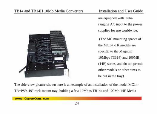
are equipped with auto-
ranging AC input to the power
supplies for use worldwide.
(The MC mounting spaces of
the MC14 -TR models are
specific to the Magnum
10Mbps (TB14) and 100MB
(14E) series, and do not permit
other models or other sizes to
be put in the tray).
The side-view picture shown here is an example of an installation of the model MC14-
TR+PS9, 19” rack-mount tray, holding a few 10Mbps TB14s and 100Mb 14E Media
TB14 and TB14H 10Mb Media Converters Installation and User Guide
25
www GarrettCom com. .
Converters, each with their power input plugged into the built-in common AC power
supply in the rear area of the tray. (PS units that come with the MC’s are not used).
Metal mounting screws in the bottom-front hold each of the media converters secure in
the tray, separately removable for service. The dual LEDs permit viewing operating
status of the Media Converters from any angle.
TB14 and TB14H 10Mb Media Converters Installation and User Guide
26
www GarrettCom com. .
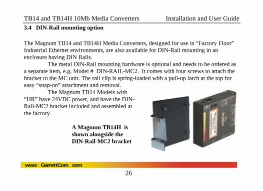
3.4 DIN-Rail mounting option The Magnum TB14 and TB14H Media Converters, designed for use in “Factory Floor” Industrial Ethernet environments, are also available for DIN-Rail mounting in an enclosure having DIN Rails.
The metal DIN-Rail mounting hardware is optional and needs to be ordered as a separate item, e.g. Model # DIN-RAIL-MC2. It comes with four screws to attach the bracket to the MC unit. The rail clip is spring-loaded with a pull-up latch at the top for easy “snap-on” attachment and removal.
The Magnum TB14 Models with “HR” have 24VDC power, and have the DIN-Rail-MC2 bracket included and assembled at the factory.
A Magnum TB14H is shown alongside the DIN-Rail-MC2 bracket
TB14 and TB14H 10Mb Media Converters Installation and User Guide
27
www GarrettCom com. .
3.5 Calculating Overall Segment Distance Important Note: Special consideration must be given to maximum cable
segment lengths of a Magnum TB14 and TB14H Media Converter. It is recommended
that IEEE 802.3 specifications for overall maximum segment distances be adhered to in
order to maintain optimum network performance. (See also Technical Specs, Maximum
Standard Ethernet Segment Distances, Section 1.1 of this manual.)
When installing the Magnum TB14s Media Converter, it is important to consider the
combined overall segment length of both of the attached media types. The overall
segment length is calculated by adding together the segment lengths on both sides of the
Magnum Media Converters. Cable segment length on each side of the Media Converter
is measured as a percentage of the maximum allowable standard media distance for the
given media type. The percentages, when added together, must not exceed 100%.
TB14 and TB14H 10Mb Media Converters Installation and User Guide
28
www GarrettCom com. .
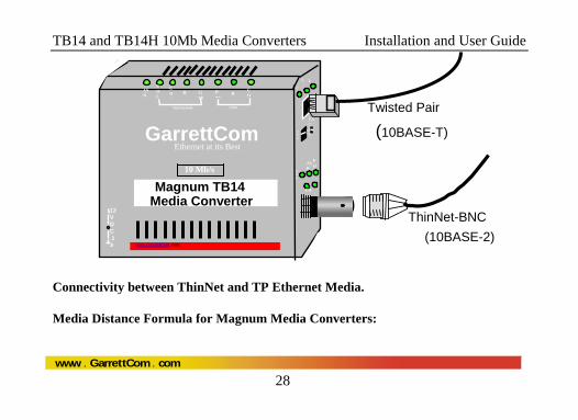
Connectivity between ThinNet and TP Ethernet Media.
Media Distance Formula for Magnum Media Converters:
Link
R RPwr
COAX TWISTED PAIR
C
12VDC .1A
UP LIN
A
Magnum TB14 Media Converter
JAB
POL
COL
www.GarrettCom .com
10 Mb/s
EXT INT
X =
CA
PWR
JAB
PO
L
CO
GarrettCom Ethernet at its Best
ThinNet-BNC(10BASE-2)
Twisted Pair
(10BASE-T)
TB14 and TB14H 10Mb Media Converters Installation and User Guide
29
www GarrettCom com. .
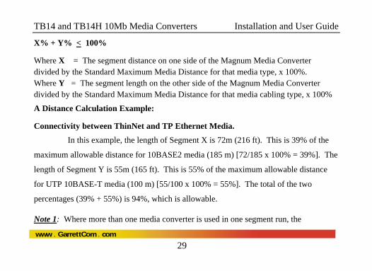
X% + Y% < 100%
Where X = The segment distance on one side of the Magnum Media Converter divided by the Standard Maximum Media Distance for that media type, x 100%. Where Y = The segment length on the other side of the Magnum Media Converter divided by the Standard Maximum Media Distance for that media cabling type, x 100%
A Distance Calculation Example:
Connectivity between ThinNet and TP Ethernet Media.
In this example, the length of Segment X is 72m (216 ft). This is 39% of the
maximum allowable distance for 10BASE2 media (185 m) [72/185 x 100% = 39%]. The
length of Segment Y is 55m (165 ft). This is 55% of the maximum allowable distance
for UTP 10BASE-T media (100 m) [55/100 x 100% = 55%]. The total of the two
percentages (39% + 55%) is 94%, which is allowable.
Note 1: Where more than one media converter is used in one segment run, the
TB14 and TB14H 10Mb Media Converters Installation and User Guide
30
www GarrettCom com. .
percentages for all of the cabling lengths in the run must be added together and must not
exceed 100%.
Note 2: If the total segment distance calculation result is greater than 100%, consider
using a Magnum Repeater so that each cable type can be 100% of its maximum allowed
length.
Note 3: The maximum number of 10Mb Magnum BNC Media Converters that can be
used in series is three. The cumulative noise from more units together causes packet
alignment errors and excessive dropped packets.
TB14 and TB14H 10Mb Media Converters Installation and User Guide
31
www GarrettCom com. .
3.6 Connecting Ethernet Media It is recommended that both of the media (TP and BNC) be connected with
power off so that both ports are connected when power is applied to the logic in the
electronics. If power is on, connect the Twisted Pair media before the BNC media. If
BNC is connected before TP with power on, it can create a Jabber condition, in which
case the JAB LED will come on and no packets will be processed.
See Sections 4.4 for details of the LEDs on the media converter models.
3.6.1 Connecting Twisted Pair (RJ-45 ports) The following procedure describes how to connect a 10BASE-T twisted pair
segment to the RJ-45 port on the Magnum Media Converters. The procedure is the same
for both unshielded and shielded twisted pair segments.
1. Using standard 10BASE-T media, insert either end of the cable with an RJ-45
TB14 and TB14H 10Mb Media Converters Installation and User Guide
32
www GarrettCom com. .
plug into the RJ-45 connector of the Magnum Media Converter.
2. Connect the other end of the cable to the corresponding device.
Use the LINK LED to ensure proper connectivity by noting that the LED will be
illuminated when the units are powered and proper connections established. If the LINK
LED is not illuminated, change the setting of the up-link switch (See Section 4.6 for up-
link switch information.) If this does not help, ensure that the cable is connected
properly at both ends and is not defective.
3.6.2 Connecting ThinNet (10BASE2) Note: connect TP media before connecting BNC media if power is on in the
Media Converter unit. See Section 3.6 Connecting Media above.
Connect the ThinNet coax cable to the BNC connector on the TB14s Media
TB14 and TB14H 10Mb Media Converters Installation and User Guide
33
www GarrettCom com. .
Converter in the same manner as is done for any standard BNC connection. Be sure that
the BNC segment is properly terminated using a standard “T” connector.
The TB14s media converter is also equipped with “Terminator
Switch” (∝-50Ω), which can be used to eliminate the standard “T” connector by moving
the “Terminator Switch” to 50Ω. See Section 4.5 BNC port, Internal Termination Switch for details.
TB14 and TB14H 10Mb Media Converters Installation and User Guide
34
www GarrettCom com. .
4.0 OPERATION This section describes the operation of the Magnum TB14 and TB14H 10Mb
Media Converters, including power supply requirements, up-link switch functionality,
and a description of all LEDs.
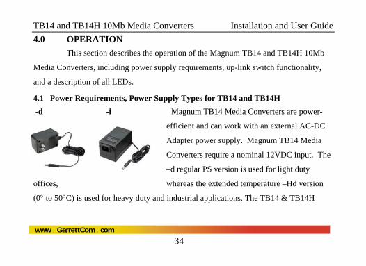
4.1 Power Requirements, Power Supply Types for TB14 and TB14H -d -i Magnum TB14 Media Converters are power-
efficient and can work with an external AC-DC
Adapter power supply. Magnum TB14 Media
Converters require a nominal 12VDC input. The
–d regular PS version is used for light duty
offices, whereas the extended temperature –Hd version
(0° to 50°C) is used for heavy duty and industrial applications. The TB14 & TB14H
TB14 and TB14H 10Mb Media Converters Installation and User Guide
35
www GarrettCom com. .
media converters are designed to be used with UL listed Class II power supplies.
The 12V DC power input has a plug of 2.5mm, center +ve , with 6 ft. cord. All the other
AC power supply info detail is provided in Technical Specifications Section 1.1.
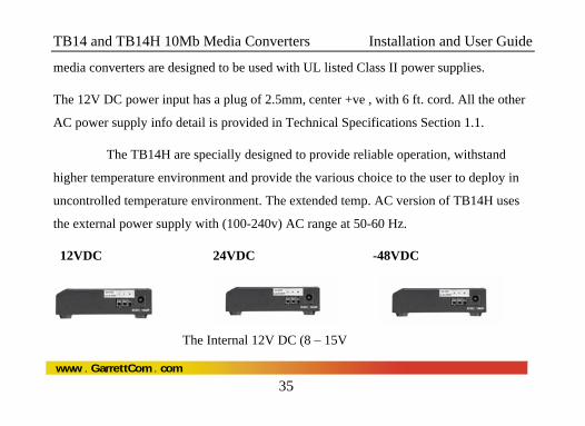
The TB14H are specially designed to provide reliable operation, withstand
higher temperature environment and provide the various choice to the user to deploy in
uncontrolled temperature environment. The extended temp. AC version of TB14H uses
the external power supply with (100-240v) AC range at 50-60 Hz.
12VDC 24VDC -48VDC
The Internal 12V DC (8 – 15V
TB14 and TB14H 10Mb Media Converters Installation and User Guide
36
www GarrettCom com. .
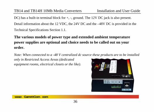
DC) has a built-in terminal block for +, -, ground. The 12V DC jack is also present.
Detail information about the 12 VDC, the 24V DC and the –48V DC is provided in the
Technical Specifications Section 1.1.
The various models of power type and extended ambient temperature power supplies are optional and choice needs to be called out on your order.
Note: When connected to a -48 V centralized dc source these products are to be installed only in Restricted Access Areas (dedicated equipment rooms, electrical closets or the like).
TB14 and TB14H 10Mb Media Converters Installation and User Guide
37
www GarrettCom com. .
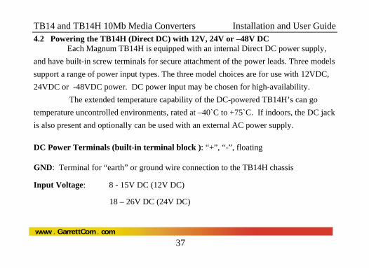
4.2 Powering the TB14H (Direct DC) with 12V, 24V or –48V DC Each Magnum TB14H is equipped with an internal Direct DC power supply, and have built-in screw terminals for secure attachment of the power leads. Three models support a range of power input types. The three model choices are for use with 12VDC, 24VDC or -48VDC power. DC power input may be chosen for high-availability. The extended temperature capability of the DC-powered TB14H’s can go temperature uncontrolled environments, rated at –40`C to +75`C. If indoors, the DC jack is also present and optionally can be used with an external AC power supply.
DC Power Terminals (built-in terminal block ): “+”, “-”, floating
GND: Terminal for “earth” or ground wire connection to the TB14H chassis
Input Voltage: 8 - 15V DC (12V DC)
18 – 26V DC (24V DC)
TB14 and TB14H 10Mb Media Converters Installation and User Guide
38
www GarrettCom com. .
30 – 60V DC (-48V DC)
Input current: 0.8 amp max.(9V DC)
0.4 amp max.(24V DC)
0.2 amp max.(-48V DC)
Power Consumption: 3 watts typical, 3.5 watts max.
4.3 TB14H, DC-powered, -48VDC, 24VDC and 12VDC Installation This section describes the proper connection of the -48VDC leads (or 24VDC, 12VDC leads) to the DC power terminal block on the Magnum TB14H hardened media converter (as shown in Figure above). The DC terminal block on the Magnum TB14H is located on the left side of the unit and is equipped with three (3) screw-down lead posts. The power terminals are identified as positive (+) and negative (-), and they are floating inside the unit so that either of the terminal may be grounded by the user if desired. The
TB14 and TB14H 10Mb Media Converters Installation and User Guide
39
www GarrettCom com. .
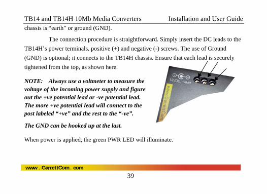
chassis is “earth” or ground (GND).
The connection procedure is straightforward. Simply insert the DC leads to the TB14H’s power terminals, positive (+) and negative (-) screws. The use of Ground (GND) is optional; it connects to the TB14H chassis. Ensure that each lead is securely tightened from the top, as shown here.
NOTE: Always use a voltmeter to measure the voltage of the incoming power supply and figure out the +ve potential lead or -ve potential lead. The more +ve potential lead will connect to the post labeled “+ve” and the rest to the “-ve”.
The GND can be hooked up at the last.
When power is applied, the green PWR LED will illuminate.
TB14 and TB14H 10Mb Media Converters Installation and User Guide
40
www GarrettCom com. .
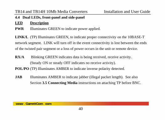
4.4 Dual LEDs, front-panel and side-panel LED Description PWR Illuminates GREEN to indicate power applied.
LINK/L (TP) Illuminates GREEN, to indicate proper connectivity on the 10BASE-T network segment. LINK will turn off in the event connectivity is lost between the ends of the twisted pair segment or a loss of power occurs in the unit or remote device.
RX/A Blinking GREEN indicates data is being received, receive activity. (Steady ON or steady OFF indicates no receive activity). POL/PO (TP) Illuminates AMBER to indicate inverse polarity detected.
JAB Illuminates AMBER to indicate jabber (illegal packet length). See also Section 3.5 Connecting Media instructions on attaching TP before BNC.
TB14 and TB14H 10Mb Media Converters Installation and User Guide
41
www GarrettCom com. .
50Ω ∝
End view, TB14’s
RJ45
BNC
Uplin
L
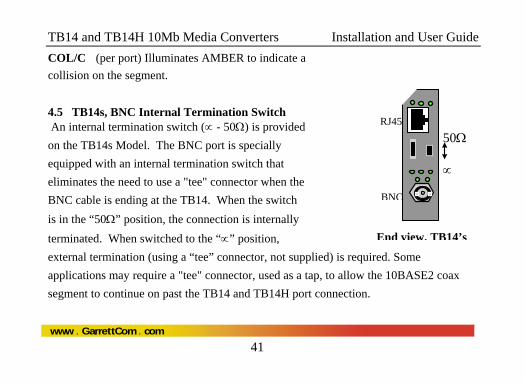
COL/C (per port) Illuminates AMBER to indicate a collision on the segment.
4.5 TB14s, BNC Internal Termination Switch An internal termination switch (∝ - 50Ω) is provided on the TB14s Model. The BNC port is specially equipped with an internal termination switch that eliminates the need to use a "tee" connector when the BNC cable is ending at the TB14. When the switch is in the “50Ω” position, the connection is internally terminated. When switched to the “∝” position, external termination (using a “tee” connector, not supplied) is required. Some applications may require a "tee" connector, used as a tap, to allow the 10BASE2 coax segment to continue on past the TB14 and TB14H port connection.
TB14 and TB14H 10Mb Media Converters Installation and User Guide
42
www GarrettCom com. .
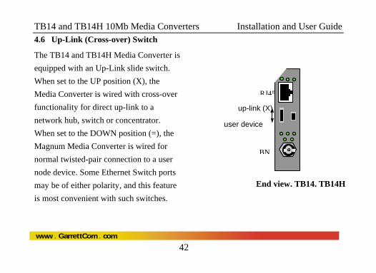
4.6 Up-Link (Cross-over) Switch
The TB14 and TB14H Media Converter is equipped with an Up-Link slide switch. When set to the UP position (X), the Media Converter is wired with cross-over functionality for direct up-link to a network hub, switch or concentrator. When set to the DOWN position (=), the Magnum Media Converter is wired for normal twisted-pair connection to a user node device. Some Ethernet Switch ports may be of either polarity, and this feature is most convenient with such switches.
End view, TB14, TB14H
up-link (X)
user device
RJ45
BNUp
= =
PWR
TB14 and TB14H 10Mb Media Converters Installation and User Guide
43
www GarrettCom com. .
5.0 TROUBLESHOOTING All Magnum Ethernet products are designed to provide reliability and
consistently high performance in all network environments. The installation of Magnum
TB14s 10 Mb/s Media Converters is a straightforward procedure (see INSTALLATION,
Section 3.0); the operation is also straightforward and is discussed in Section 4.
Should problems develop during installation or operation, this section is
intended to help locate, identify and correct these types of problems. Please follow the
suggestions listed below prior to contacting your supplier. However, if you are unsure of
the procedures described in this section or if the Magnum TB14/TB14H 10 Mb/s Media
Converter is not performing as expected, do not attempt to repair the unit; instead contact
your supplier for assistance or contact GarrettCom Customer Support.
TB14 and TB14H 10Mb Media Converters Installation and User Guide
44
www GarrettCom com. .
5.1 Before Calling for Assistance 1. If difficulty is encountered when installing or operating the unit, refer back to
the Installation Section of the applicable chapter of this manual. Also check
to make sure that the various components of the network are interoperable.
2. Check the cables and connectors to ensure that they have been properly
connected and the cables/wires have not been crimped or in some way
impaired during installation. (About 90% of network downtime can be
attributed to wiring and connector problems.)
3. Make sure that an AC power cord is properly attached to each Magnum
TB14/TB14H 10 Mb/s Media Converters unit. Be certain that each AC power
cord is plugged into a functioning electrical outlet. Use the PWR LEDs to
verify each unit is receiving power.
TB14 and TB14H 10Mb Media Converters Installation and User Guide
45
www GarrettCom com. .
4. If the problem is isolated to a network device other than the Magnum
TB14/TB14H 10 Mb/s Media Converters product, it is recommended that the
problem device is replaced with a known good device. Verify whether or not
the problem is corrected. If not, go to Step 5 below. If the problem is
corrected, the Magnum TB14/TB14H 10 Mb/s Media Converters and its
associated cables are functioning properly.
5. If the problem continues after completing Step 4 above, contact your supplier
of the Magnum TB14/TB14H 10 Mb/s Media Converters unit or if unknown,
contact GarrettCom, Inc by fax, phone or email ([email protected]) for
assistance.
TB14 and TB14H 10Mb Media Converters Installation and User Guide
46
www GarrettCom com. .
5.2 When Calling for Assistance Please be prepared to provide the following information.
1. A complete description of the problem, including the following points: a. The nature and duration of the problem; b. Situations when the problem occurs; c. The components involved in the problem; d. Any particular application that, when used, appears to create the problem; 2. An accurate list of GarrettCom product model(s)involved, with serial
number(s). Include the date(s) that you purchased the products from your supplier.
3. It is useful to include other network equipment models and related hardware, including personal computers, workstations, terminals and printers; plus, the various network media types being used. 4. A record of changes that have been made to your network configuration prior to the occurrence of the problem. Any changes to system administration procedures should all be noted in this record.
TB14 and TB14H 10Mb Media Converters Installation and User Guide
47
www GarrettCom com. .
5.3 Return Material Authorization (RMA) Procedure All returns for repair must be accompanied by a Return Material Authorization (RMA) number. To obtain an RMA number, please use this URL - https://rma.garrettcom.com/rma/rma_request_noaccount.php to fill out the form. Please have the following information readily available:
Name and phone number of your contact person. Name of your company / institution Your shipping address Product name Serial Number (or Invoice Number) Packing List Number (or Sales Order Number) Date of installation Failure symptoms, including a full description of the problem.
TB14 and TB14H 10Mb Media Converters Installation and User Guide
48
www GarrettCom com. .
GarrettCom will carefully test and evaluate all returned products, will repair products that are under warranty at no charge, and will return the warranty-repaired units to the sender with shipping charges prepaid (see Warranty Information, Appendix A, for complete details). However, if the problem or condition causing the return cannot be duplicated by GarrettCom, the unit will be returned as:
No Problem Found.
GarrettCom reserves the right to charge for the testing of non-defective units under warranty. Testing and repair of product that is not under warranty will result in a customer (user) charge.
TB14 and TB14H 10Mb Media Converters Installation and User Guide
49
www GarrettCom com. .
5.4 Shipping and Packaging Information Should you need to ship the unit back to GarrettCom, please follow these instructions:
1. Package the unit carefully. It is recommended that you use the original container if available. Units should be wrapped in a "bubble-wrap" plastic sheet or bag for shipping protection. (You may retain all connectors and this Installation Guide.)
CAUTION: Do not pack the unit in Styrofoam "popcorn" type packing material. This material may cause electro-static shock damage to the unit. 2. Clearly mark the Return Material Authorization (RMA) number on the outside of the shipping container. 3. GarrettCom is not responsible for your return shipping charges. 4. Ship the package to:
GarrettCom, Inc. 47823 Westinghouse Dr. Fremont, CA 94539-7437
Attn.: Customer Service
TB14 and TB14H 10Mb Media Converters Installation and User Guide
50
www GarrettCom com. .
APPENDIX A: WARRANTY INFORMATION GarrettCom, Inc. warrants its products to be free from defects in materials and workmanship for a period of three (3) years from the date of shipment by GarrettCom. During this warranty period, GarrettCom will repair or, at its option, replace components in the products that prove to be defective at no charge other than shipping and handling, provided that the product is returned pre-paid to GarrettCom. This warranty will not be effective and void if, in the opinion of GarrettCom, the product has been damaged by misuse, misapplication, or as a result of service or modification other than by GarrettCom. GarrettCom reserves the right to make a charge for handling and inspecting any product returned for warranty repair which turns out not to be faulty. Please complete the warranty card as this acts as a product registration, and mail it to GarrettCom within two weeks of your purchase.