Embed Size (px)
Citation preview
GAS STAINLESS COOKTOP
CG604D & CG905D models
INSTALLATION GUIDE
HK SG
590633E 10.18
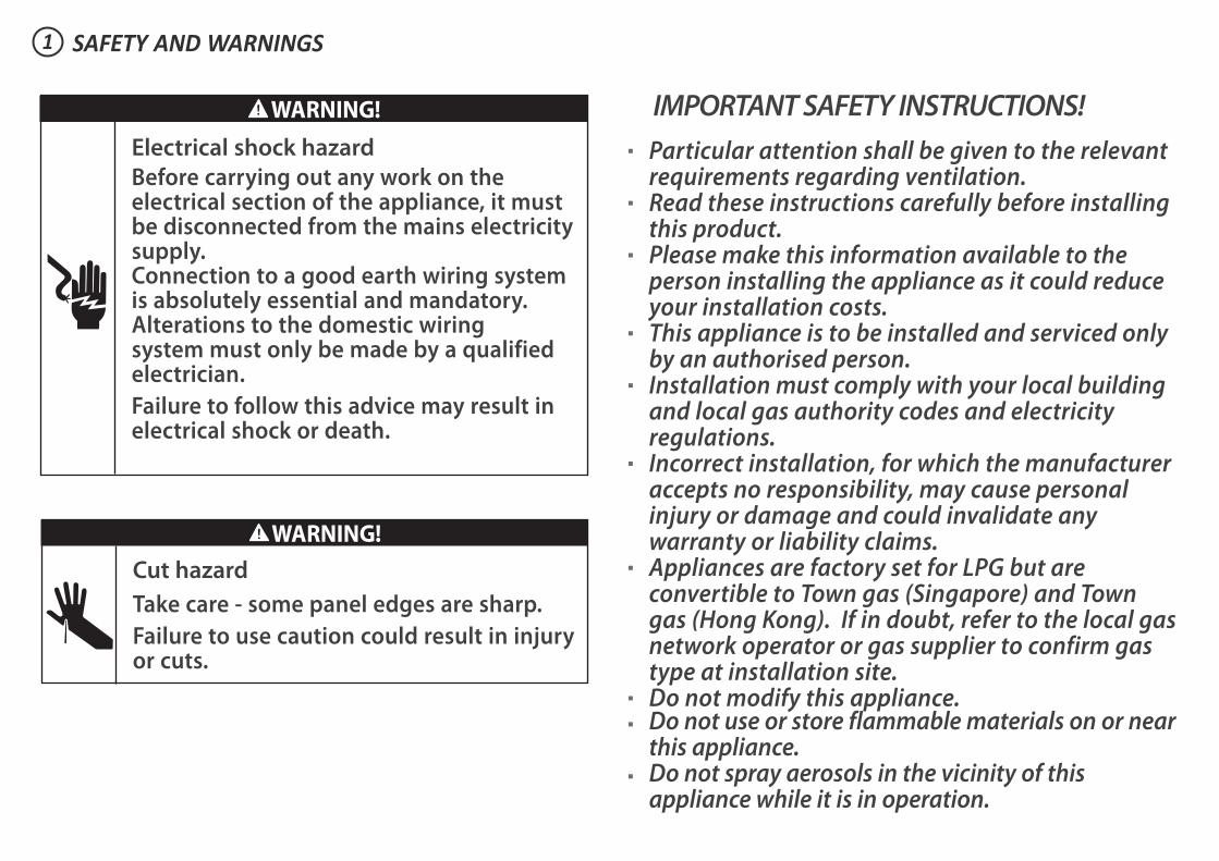
IMPORTANT SAFETY INSTRUCTIONS!
Particular attention shall be given to the relevant requirements regarding ventilation.
Read these instructions carefully before installing this product.
Please make this information available to the person installing the appliance as it could reduce your installation costs.
This appliance is to be installed and serviced only by an authorised person.
Installation must comply with your local building and local gas authority codes and electricity regulations.
Incorrect installation, for which the manufacturer accepts no responsibility, may cause personal injury or damage and could invalidate any warranty or liability claims.
Appliances are factory set for LPG but are convertible to Town gas (Singapore) and Town gas (Hong Kong). If in doubt, refer to the local gas network operator or gas supplier to confirm gas type at installation site.
Do not modify this appliance. Do not use or store flammable materials on or near
this appliance. Do not spray aerosols in the vicinity of this
appliance while it is in operation.
SAFETY AND WARNINGS1
WARNING!
Cut hazard
Take care - some panel edges are sharp.
Failure to use caution could result in injury or cuts.
WARNING!
Electrical shock hazard
Before carrying out any work on the electrical section of the appliance, it must be disconnected from the mains electricity supply.Connection to a good earth wiring system is absolutely essential and mandatory.Alterations to the domestic wiring system must only be made by a qualified electrician.
Failure to follow this advice may result in electrical shock or death.
3SAFETY AND WARNINGS1
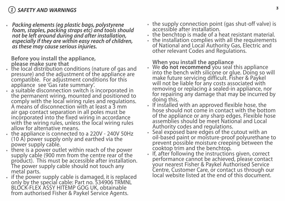
Packing elements (eg plastic bags, polystyrene foam, staples, packing straps etc) and tools should not be left around during and after installation, especially if they are within easy reach of children, as these may cause serious injuries.
Before you install the appliance, please make sure that the local distribution conditions (nature of gas and
pressure) and the adjustment of the appliance are compatible. For adjustment conditions for this appliance see ‘Gas rate summary’.
a suitable disconnection switch is incorporated in the permanent wiring, mounted and positioned to comply with the local wiring rules and regulations. A means of disconnection with at least a 3 mm air gap contact separation in all poles must be incorporated into the fixed wiring in accordance with the wiring rules, unless the local wiring rules allow for alternative means.
the appliance is connected to a 220V - 240V 50Hz (10 A) power supply only and earthed via the power supply cable.
there is a power outlet within reach of the power supply cable (900 mm from the centre rear of the product). This must be accessible after installation. The power supply cable should not touch any metal parts.
if the power supply cable is damaged, it is replaced only by the special cable: Part no. 534906 TRMNL BLOCK-FLEX ASSY HITEMP GOG UK, obtainable from authorised Fisher & Paykel Service Agents.
the supply connection point (gas shut-off valve) is accessible after installation.
the benchtop is made of a heat resistant material. the installation complies with all the requirements
of National and Local Authority Gas, Electric and other relevant Codes and Regulations.
When you install the appliance We do not recommend you seal this appliance
into the bench with silicone or glue. Doing so will make future servicing difficult. Fisher & Paykel will not be liable for any costs associated with removing or replacing a sealed-in appliance, nor for repairing any damage that may be incurred by doing this.
If installed with an approved flexible hose, the hose should not come in contact with the bottom of the appliance or any sharp edges. Flexible hose assemblies should be meet National and Local Authority codes and regulations.
Seal exposed bare edges of the cutout with an oil-based paint or moisture-proof polyurethane to prevent possible moisture creeping between the cooktop trim and the benchtop.
If, after following the instructions given, correct performance cannot be achieved, please contact your nearest Fisher & Paykel Authorised Service Centre, Customer Care, or contact us through our local website listed at the end of this document.

PARTS SUPPLIED2
Wok stand (1) Fibre washers (1)Foam tape (1)
Clamping brackets (4)and screws (4)
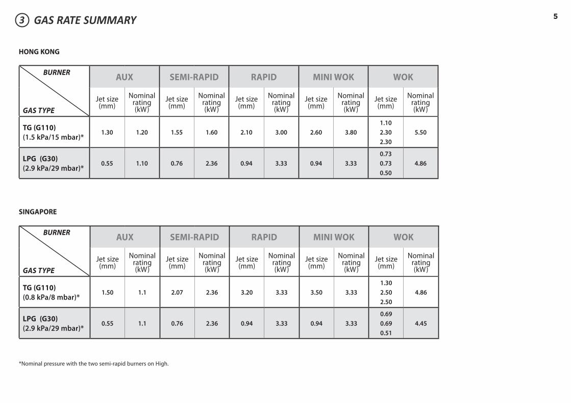
3 GAS RATE SUMMARYAll appliances are factory set for LPG or Town Gas.
CG604D CG905D
SEMI-RAPID SEMI-RAPIDSEMI-RAPID SEMI-RAPID
MINI WOK RAPID
WOK
AUX AUX
Gas Elbow (1) Elbow 1/2“ BSP external thread (1)
LPG test point adaptor (1)
53 GAS RATE SUMMARY
HONG KONG
SINGAPORE
BURNER
GAS TYPE
AUX SEMI-RAPID RAPID MINI WOK WOK
Jet size (mm)
Nominal rating (kW)
Jet size (mm)
Nominal rating (kW)
Jet size (mm)
Nominal rating (kW)
Jet size (mm)
Nominal rating (kW)
Jet size (mm)
Nominal rating (kW)
TG (G110)
(1.5 kPa/15 mbar)*1.30 1.20 1.55 1.60 2.10 3.00 2.60 3.80
1.10
2.30
2.30
5.50
LPG (G30)
(2.9 kPa/29 mbar)*0.55 1.10 0.76 2.36 0.94 3.33 0.94 3.33
0.73
0.73
0.50
4.86
BURNER
GAS TYPE
AUX SEMI-RAPID RAPID MINI WOK WOK
Jet size (mm)
Nominal rating (kW)
Jet size (mm)
Nominal rating (kW)
Jet size (mm)
Nominal rating (kW)
Jet size (mm)
Nominal rating (kW)
Jet size (mm)
Nominal rating (kW)
TG (G110)
(0.8 kPa/8 mbar)*1.50 1.1 2.07 2.36 3.20 3.33 3.50 3.33
1.30
2.50
2.50
4.86
LPG (G30)
(2.9 kPa/29 mbar)*0.55 1.1 0.76 2.36 0.94 3.33 0.94 3.33
0.69
0.69
0.51
4.45
*Nominal pressure with the two semi-rapid burners on High.
64 PRODUCT & CABINETRY DIMENSIONS
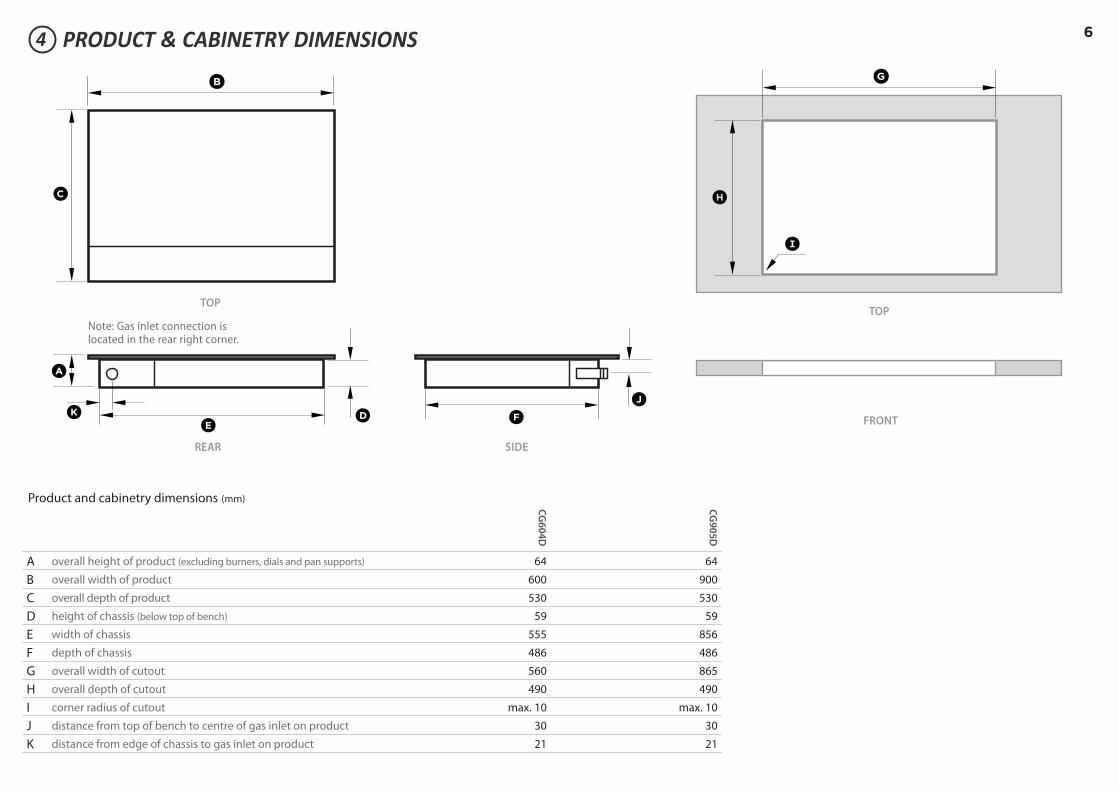
Product and cabinetry dimensions (mm)
CG
60
4D
CG
90
5D
A overall height of product (excluding burners, dials and pan supports) 64 64
B overall width of product 600 900
C overall depth of product 530 530
D height of chassis (below top of bench) 59 59
E width of chassis 555 856
F depth of chassis 486 486
G overall width of cutout 560 865
H overall depth of cutout 490 490
I corner radius of cutout max. 10 max. 10
J distance from top of bench to centre of gas inlet on product 30 30
K distance from edge of chassis to gas inlet on product 21 21
A
K D
B
E
C
G
FJ
H
I
Note: Gas inlet connection is located in the rear right corner.
TOPTOP
REAR
FRONT
SIDE
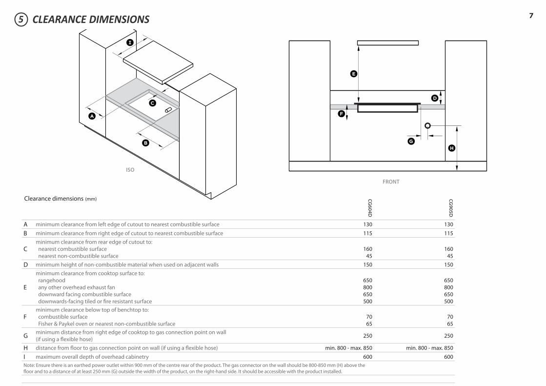
75 CLEARANCE DIMENSIONS
Clearance dimensions (mm) CG
60
4D
CG
90
5D
A minimum clearance from left edge of cutout to nearest combustible surface 130 130
B minimum clearance from right edge of cutout to nearest combustible surface 115 115
Cminimum clearance from rear edge of cutout to:
nearest combustible surface
nearest non-combustible surface
160
45
160
45
D minimum height of non-combustible material when used on adjacent walls 150 150
E
minimum clearance from cooktop surface to:
rangehood
any other overhead exhaust fan
downward facing combustible surface
downwards-facing tiled or fi re resistant surface
650
800
650
500
650
800
650
500
Fminimum clearance below top of benchtop to:
combustible surface
Fisher & Paykel oven or nearest non-combustible surface
70
65
70
65
Gminimum distance from right edge of cooktop to gas connection point on wall
(if using a fl exible hose)250 250
H distance from fl oor to gas connection point on wall (if using a fl exible hose) min. 800 - max. 850 min. 800 - max. 850
I maximum overall depth of overhead cabinetry 600 600
Note: Ensure there is an earthed power outlet within 900 mm of the centre rear of the product. The gas connector on the wall should be 800-850 mm (H) above the
fl oor and to a distance of at least 250 mm (G) outside the width of the product, on the right-hand side. It should be accessible with the product installed.
FRONT
ISO
E
H
D
F
G
A
I
B
C
86
98
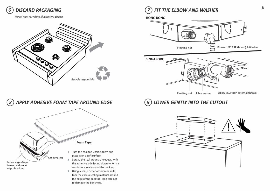
7DISCARD PACKAGING
LOWER GENTLY INTO THE CUTOUTAPPLY ADHESIVE FOAM TAPE AROUND EDGE
FIT THE ELBOW AND WASHER
Recycle responsibly
Model may vary from illustrations shown
Foam Tape
Adhesive side
Ensure edge of tape
lines up with outer
edge of cooktop
1 Turn the cooktop upside down and
place it on a soft surface.
2 Spread the seal around the edges, with
the adhesive side facing down to form a
continuous seal around the cooktop.
3 Using a sharp cutter or trimmer knife,
trim the excess sealing material around
the edge of the cooktop. Take care not
to damage the benchtop.
Floating nut Elbow (1/2” BSP thread) & Washer
Floating nut Fibre washer Elbow (1/2” BSP external thread)
HONG KONG
SINGAPORE
911
1312
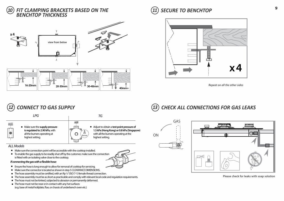
10 SECURE TO BENCHTOP
CHECK ALL CONNECTIONS FOR GAS LEAKSCONNECT TO GAS SUPPLY
FIT CLAMPING BRACKETS BASED ON THE BENCHTOP THICKNESS
16-20mm 20-30mm
x 4
30-40mm40mm+
view from below
x 4
Repeat on all the other sides
GAS
ON
GAS
ON
Please check for leaks with soap solution
TG
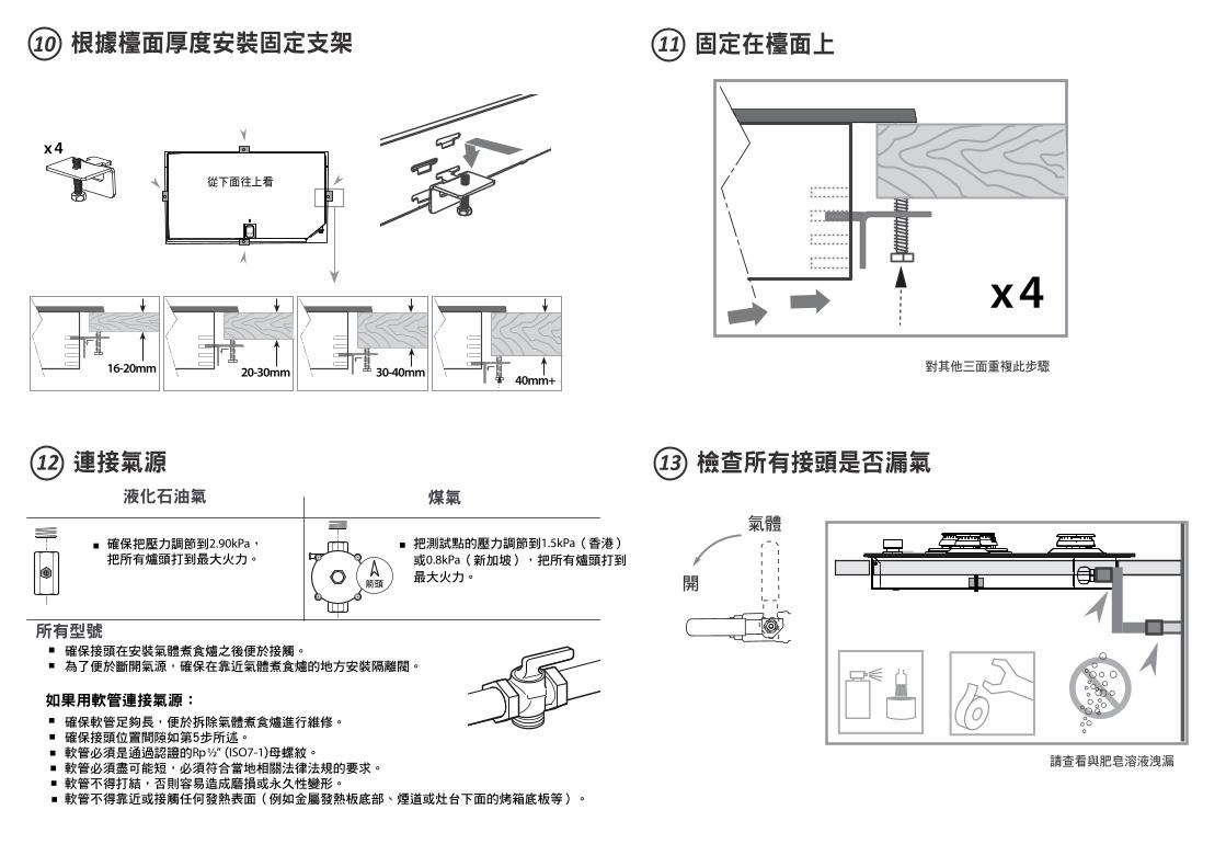
ALL ModelsMake sure the connection point will be accessible with the cooktop installed.
To enable the gas supply to be readily shut off by the customer, make sure the connection
is fitted with an isolating valve close to the cooktop.
Adjust to obtain a test point pressure of 1.5 kPa (Hong Kong) or 0.8 kPa (Singapore) with all the burners operating at the
highest setting.
Ensure the hose is long enough to allow for removal of cooktop for servicing.
Make sure the connector is located as shown in step 5 CLEARANCE DIMENSIONS.
The hose assembly must be certified, with an Rp ½” (ISO 7‐1) female thread connection.
The hose assembly must be as short as practicable and comply with relevant local code and regulation requirements.
The hose must not be kinked, subjected to abrasion or permanently deformed.
The hose must not be near or in contact with any hot surfaces
(e.g. base of metal hotlplate, flue, or chassis of underbench oven etc.)
If connecting the gas with a flexible hose:
LPG
Make sure the supply pressure is regulated to 2.90 kPa, with
all the burners operating at
highest setting.Arrow
10
Duplicate data label
14
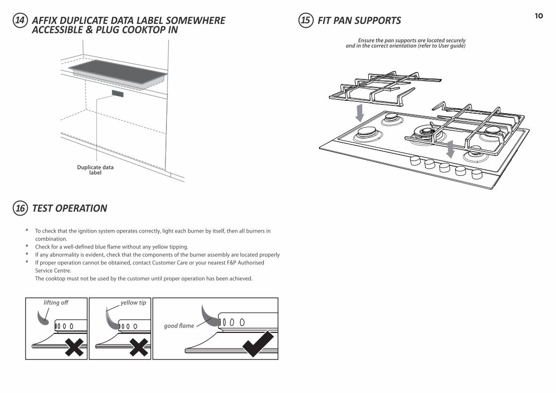
16
15AFFIX DUPLICATE DATA LABEL SOMEWHERE ACCESSIBLE & PLUG COOKTOP IN
TEST OPERATION
FIT PAN SUPPORTS
yellow tiplifting off
good flame
To check that the ignition system operates correctly, light each burner by itself, then all burners in
combination. Check for a well‐defined blue flame without any yellow tipping. If any abnormality is evident, check that the components of the burner assembly are located properly If proper operation cannot be obtained, contact Customer Care or your nearest F&P Authorised
Service Centre.
The cooktop must not be used by the customer until proper operation has been achieved.
Ensure the pan supports are located securelyand in the correct orientation (refer to User guide)
1117 FINAL CHECKLIST
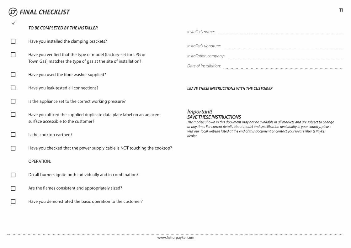
Important! SAVE THESE INSTRUCTIONSThe models shown in this document may not be available in all markets and are subject to change
at any time. For current details about model and specification availability in your country, please
visit our local website listed at the end of this document or contact your local Fisher & Paykel
dealer.
www.fi sherpaykel.com
TO BE COMPLETED BY THE INSTALLER
Have you installed the clamping brackets?
Have you verified that the type of model (factory-set for LPG or
Town Gas) matches the type of gas at the site of installation?
Have you used the fibre washer supplied?
Have you leak-tested all connections?
Is the appliance set to the correct working pressure?
Have you affixed the supplied duplicate data plate label on an adjacent
surface accessible to the customer?
Is the cooktop earthed?
Have you checked that the power supply cable is NOT touching the cooktop?
OPERATION:
Do all burners ignite both individually and in combination?
Are the flames consistent and appropriately sized?
Have you demonstrated the basic operation to the customer?
Installer’s name:
Installer’s signature:
Installation company:
Date of installation:
LEAVE THESE INSTRUCTIONS WITH THE CUSTOMER

CG604D型和CG905D型
氣體煮食爐
安裝說明書
HK SG
590633E 10.18
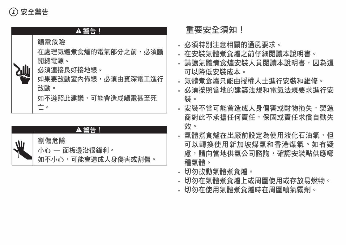
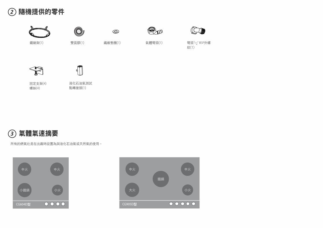
重要安全須知!
必須特別注意相關的通風要求。 在安裝氣體煮食爐之前仔細閱讀本說明書。 請讓氣體煮食爐安裝人員閱讀本說明書,因為這可以降低安裝成本。
氣體煮食爐只能由授權人士進行安裝和維修。 必須按照當地的建築法規和電氣法規要求進行安裝。
安裝不當可能會造成人身傷害或財物損失,製造商對此不承擔任何責任,保固或責任求償自動失效。
氣體煮食爐在出廠前設定為使用液化石油氣,但可以轉換使用新加坡煤氣和香港煤氣。如有疑慮,請向當地供氣公司諮詢,確認安裝點供應哪種氣體。
切勿改動氣體煮食爐。 切勿在氣體煮食爐上或周圍使用或存放易燃物。 切勿在使用氣體煮食爐時在周圍噴氣霧劑。
安全警告
警告!
割傷危險
小心 — 面板邊沿很鋒利。
如不小心,可能會造成人身傷害或割傷。
警告!
觸電危險
在處理氣體煮食爐的電氣部分之前,必須斷
開總電源。
必須連接良好接地線。
如果要改動室內佈線,必須由資深電工進行
改動。
如不遵照此建議,可能會造成觸電甚至死
亡。
1
安全警告
在安裝過程中和安裝之後,切勿把包裝材料(例如塑膠袋、聚苯乙烯泡沫、搭扣和包裝帶)放在氣體煮食爐附近,尤其不能放在兒童夠得到的地方,否則可能會造成嚴重人身傷害。
在安裝氣體煮食爐之前確保 當地的供氣條件(氣體類型和壓力)與氣體煮食爐調節條件一致。參看氣體氣速摘要一節瞭解氣體煮食爐的調節條件。
在永久性佈線中安裝一個符合當地佈線法規要求的合適斷路開關。根據當地的佈線法規,安裝在固定佈線系統裡的斷路開關的所有電極的觸點氣隙間隔為3mm,除非當地佈線法規允許採用替代方法。
氣體煮食爐連接220V-240V 50Hz (10A)電源,並通過電源線中的地線接地。
在氣體煮食爐電源線所及的地方裝有電源插座(距氣體煮食爐後中心900mm)。在安裝氣體煮食爐之後,插座所在位置必須便於使用者插拔插頭。電源線不得接觸任何金屬零件。
如果電源線破損,必須用斐雪派克授權維修代理商提供的專用電源線更換:534906 TRMNL BLOCK-FLEX組件HITEMP GOG 英國
在安裝氣體煮食爐之後,氣源接頭(氣體截流閥)所在位置必須便於使用者開關氣體。
灶台用耐熱材料製成。 氣體煮食爐安裝符合國家和當地供氣公司、供電公司的要求和其他相關法律法規的要求。
在安裝氣體煮食爐時 建議你不要用矽膠或膠水把氣體煮食爐固定在灶台上,否則日後很難維修。斐雪派克不承擔與拆卸或安裝膠粘氣體煮食爐相關的任何費用,對在此過程中可能發生的修理損壞不承擔任何責任。
如果安裝符合法規要求的軟管,軟管不應接觸氣體煮食爐底面或任何鋒利邊沿。軟管應該符合國家和當地供氣法律法規的要求。
開口裸露邊沿用油漆或防水聚氨酯密封,防止濕氣滲入氣體煮食爐邊沿和灶台之間。
如果在根據氣體煮食爐安裝說明安裝之後,氣體煮食爐達不到要求的性能,請聯絡最近的斐雪派克授權服務中心或客戶服務部,或者登錄本指南封底列出的地區網站聯絡我們。
1
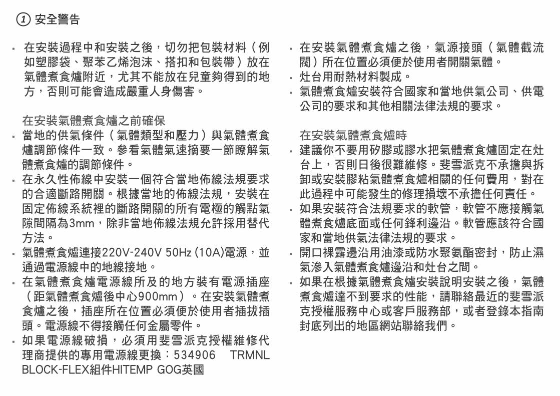
隨機提供的零件2
鐵鍋架(1) 纖維墊圈(1)雙面膠(1)
固定支架(4)
螺絲(4)
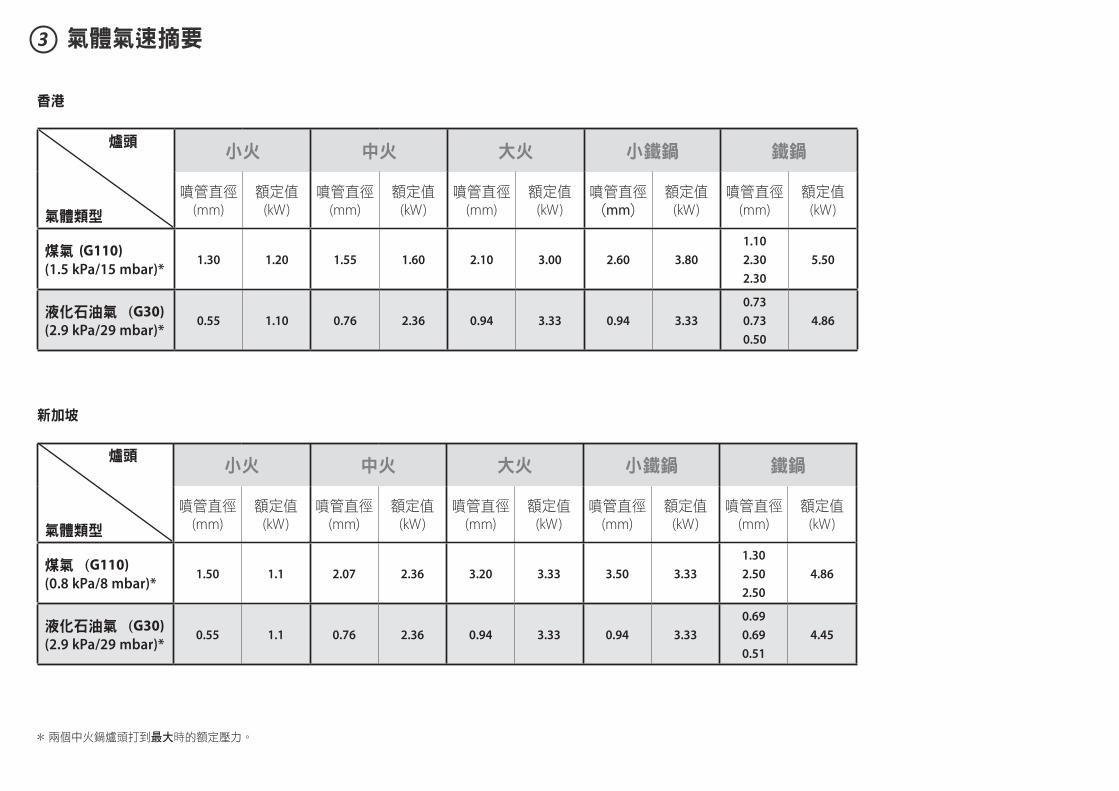
3 氣體氣速摘要
所有的燃氣灶是在出廠時設置為與液化石油氣或天然氣的使用。
CG604D型 CG905D型
中火 中火中火 中火
小鐵鍋 大火
鐵鍋
小火 小火
氣體彎頭(1) 彎頭1/2" BSP外螺
紋(1)
液化石油氣測試
點轉接頭(1)
3 氣體氣速摘要
香港
新加坡
爐頭
氣體類型
小火 中火 大火 小鐵鍋 鐵鍋
噴管直徑(mm)
額定值(kW)
噴管直徑(mm)
額定值(kW)
噴管直徑(mm)
額定值(kW)
噴管直徑(mm)
額定值(kW)
噴管直徑(mm)
額定值(kW)
煤氣 (G110)
(1.5 kPa/15 mbar)*1.30 1.20 1.55 1.60 2.10 3.00 2.60 3.80
1.10
2.30
2.30
5.50
液化石油氣 (G30)
(2.9 kPa/29 mbar)*0.55 1.10 0.76 2.36 0.94 3.33 0.94 3.33
0.73
0.73
0.50
4.86
爐頭
氣體類型
小火 中火 大火 小鐵鍋 鐵鍋
噴管直徑(mm)
額定值(kW)
噴管直徑(mm)
額定值(kW)
噴管直徑(mm)
額定值(kW)
噴管直徑(mm)
額定值(kW)
噴管直徑(mm)
額定值(kW)
煤氣 (G110)
(0.8 kPa/8 mbar)*1.50 1.1 2.07 2.36 3.20 3.33 3.50 3.33
1.30
2.50
2.50
4.86
液化石油氣 (G30)
(2.9 kPa/29 mbar)*0.55 1.1 0.76 2.36 0.94 3.33 0.94 3.33
0.69
0.69
0.51
4.45
* 兩個中火鍋爐頭打到最大時的額定壓力。
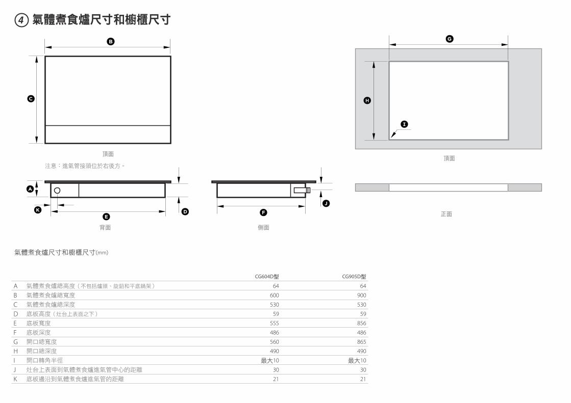
4 氣體煮食爐尺寸和櫥櫃尺寸
氣體煮食爐尺寸和櫥櫃尺寸(mm)
CG604D型 CG905D型
A 氣體煮食爐總高度(不包括爐頭、旋鈕和平底鍋架) 64 64
B 氣體煮食爐總寬度 600 900
C 氣體煮食爐總深度 530 530
D 底板高度(灶台上表面之下) 59 59
E 底板寬度 555 856
F 底板深度 486 486
G 開口總寬度 560 865
H 開口總深度 490 490
I 開口轉角半徑 最大10 最大10
J 灶台上表面到氣體煮食爐進氣管中心的距離 30 30
K 底板邊沿到氣體煮食爐進氣管的距離 21 21
A
K D
B
E
C
G
FJ
H
I
注意:進氣管接頭位於右後方。
頂面頂面
背面
正面
側面
A
I
B
C
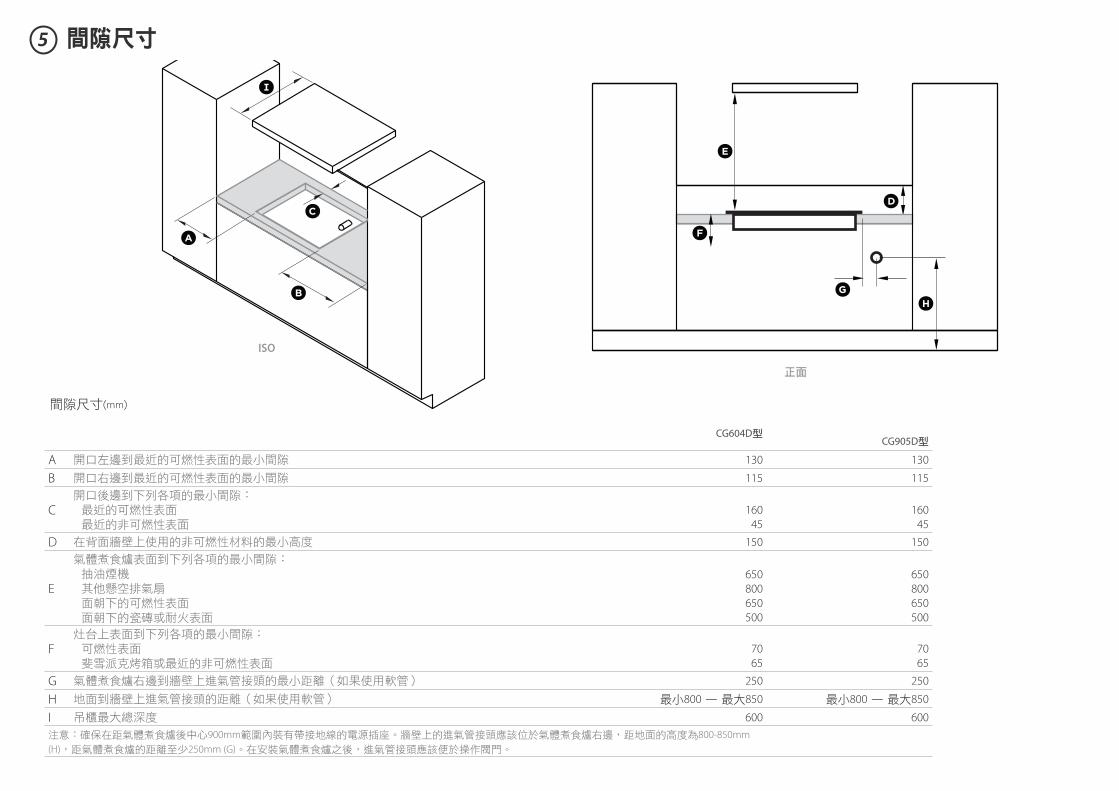
5 間隙尺寸
間隙尺寸(mm)
CG604D型CG905D型
A 開口左邊到最近的可燃性表面的最小間隙 130 130
B 開口右邊到最近的可燃性表面的最小間隙 115 115
C開口後邊到下列各項的最小間隙: 最近的可燃性表面 最近的非可燃性表面
160
45
160
45
D 在背面牆壁上使用的非可燃性材料的最小高度 150 150
E
氣體煮食爐表面到下列各項的最小間隙: 抽油煙機 其他懸空排氣扇 面朝下的可燃性表面 面朝下的瓷磚或耐火表面
650
800
650
500
650
800
650
500
F灶台上表面到下列各項的最小間隙: 可燃性表面 斐雪派克烤箱或最近的非可燃性表面
70
65
70
65
G 氣體煮食爐右邊到牆壁上進氣管接頭的最小距離(如果使用軟管) 250 250
H 地面到牆壁上進氣管接頭的距離(如果使用軟管) 最小800 — 最大850 最小800 — 最大850
I 吊櫃最大總深度 600 600
注意:確保在距氣體煮食爐後中心900mm範圍內裝有帶接地線的電源插座。牆壁上的進氣管接頭應該位於氣體煮食爐右邊,距地面的高度為800-850mm
(H),距氣體煮食爐的距離至少250mm (G)。在安裝氣體煮食爐之後,進氣管接頭應該便於操作閥門。
正面
ISO
E
H
D
F
G
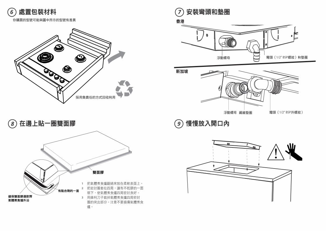
6
98
7處置包裝材料
慢慢放入開口內在邊上貼一圈雙面膠
安裝彎頭和墊圈
採用負責任的方式回收利用
你購買的型號可能與圖中所示的型號有差異
1 把氣體煮食爐翻過來放在柔軟表面上。
2 把密封圈套在四周,讓有不乾膠的一面
朝下,使氣體煮食爐四周密封良好。
3 用鋒利刀子裁掉氣體煮食爐四周密封
圈的突出部分。注意不要損傷氣體煮食
爐。
浮動螺母 彎頭(1/2" BSP螺紋)和墊圈
浮動螺母 纖維墊圈 彎頭(1/2" BSP外螺紋)
香港
新加坡
11
1312
10 固定在檯面上
檢查所有接頭是否漏氣連接氣源
根據檯面厚度安裝固定支架
16-20mm 20-30mm
x 4
30-40mm40mm+
從下面往上看
x 4
對其他三面重複此步驟
GAS
ON
1.5kPa0.8kPa
Rp ½” ISO7-1
2.90kPa
請查看與肥皂溶液洩漏
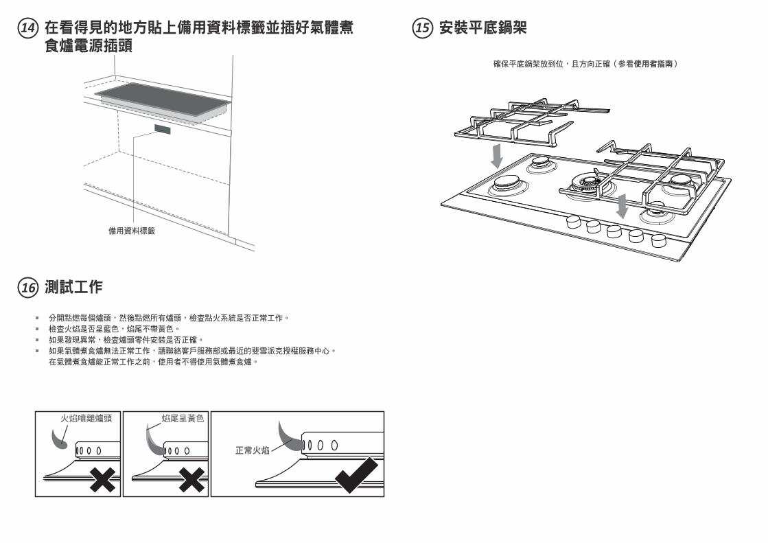
備用資料標籤
14
16
15在看得見的地方貼上備用資料標籤並插好氣體煮食爐電源插頭
測試工作
安裝平底鍋架
分開點燃每個爐頭,然後點燃所有爐頭,檢查點火系統是否正常工作。
檢查火焰是否呈藍色,焰尾不帶黃色。
如果發現異常,檢查爐頭零件安裝是否正確。
如果氣體煮食爐無法正常工作,請聯絡客戶服務部或最近的斐雪派克授權服務中心。
在氣體煮食爐能正常工作之前,使用者不得使用氣體煮食爐。
確保平底鍋架放到位,且方向正確(參看使用者指南)
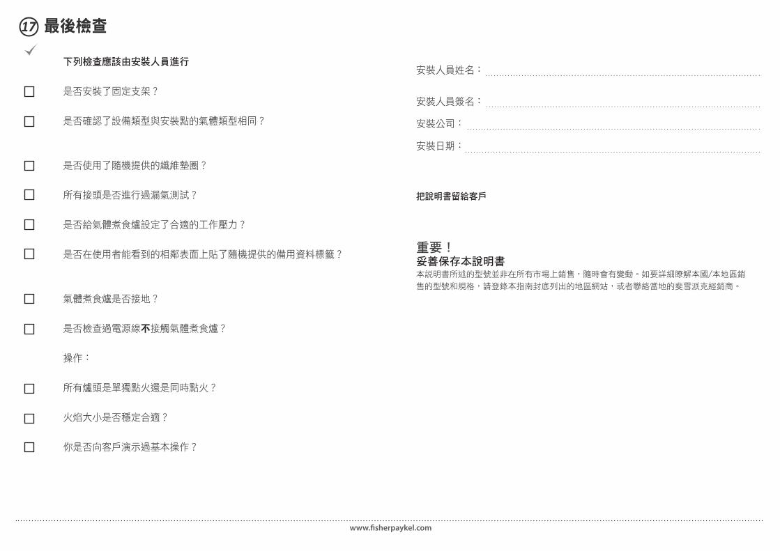
17 最後檢查
重要! 妥善保存本說明書本說明書所述的型號並非在所有市場上銷售,隨時會有變動。如要詳細瞭解本國/本地區銷
售的型號和規格,請登錄本指南封底列出的地區網站,或者聯絡當地的斐雪派克經銷商。
www.fi sherpaykel.com
下列檢查應該由安裝人員進行
是否安裝了固定支架?
是否確認了設備類型與安裝點的氣體類型相同?
是否使用了隨機提供的纖維墊圈?
所有接頭是否進行過漏氣測試?
是否給氣體煮食爐設定了合適的工作壓力?
是否在使用者能看到的相鄰表面上貼了隨機提供的備用資料標籤?
氣體煮食爐是否接地?
是否檢查過電源線不接觸氣體煮食爐?
操作:
所有爐頭是單獨點火還是同時點火?
火焰大小是否穩定合適?
你是否向客戶演示過基本操作?
安裝人員姓名:
安裝人員簽名:
安裝公司:
安裝日期:
把說明書留給客戶