Embed Size (px)
Citation preview
Gemini Ground Layer Adaptive Optics Feasibility Study Report Document number: GLAO-PRO-001 Version: 1.0 Status:
Prepared by : Name(s) and Signature(s) Organization Date
Approved By: Name and Signature Organization Date
Released By: Name and Signature Organization Date
University of Durham Centre for Advanced
Gemini Ground Layer Adaptive Optics
Feasibility Study Report
Doc #: GLAO-PRO-001 Version: 1.0 Date: 23 February, 2005 Page: 2
____________________________________________________________
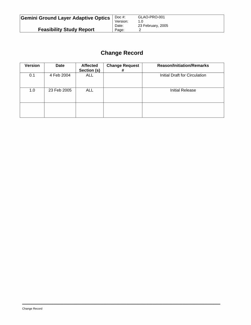
Change Record
Change Record
Version Date Affected Section (s)
Change Request #
Reason/Initiation/Remarks
0.1 4 Feb 2004 ALL Initial Draft for Circulation
1.0 23 Feb 2005 ALL Initial Release
Gemini Ground Layer Adaptive Optics
Feasibility Study Report
Doc #: GLAO-PRO-001 Version: 1.0 Date: 23 February, 2005 Page: 3
____________________________________________________________
Executive summary
Table of Contents
1.0 EXECUTIVE SUMMARY..........................................................................................................................6 1.1 THE SCIENCE CASE FOR GLAO ...............................................................................................................6 1.2 MODELING GLAO....................................................................................................................................6 1.3 BASELINE GLAO DESIGN ........................................................................................................................7 1.4 DESIGNING GLAO...................................................................................................................................7 1.5 FUTURE DECISIONS FOR GLAO ...............................................................................................................8
2.0 INTRODUCTION ......................................................................................................................................9 2.1 ORGANIZATION OF THE PROJECT AND PROJECT TEAMS ..............................................................................9 2.2 PROJECT PLAN - ORIGINAL.....................................................................................................................10 2.3 CHANGE TO PROJECT PLAN AFTER SCIENCE WORKSHOP ..........................................................................11 2.4 GLAO PHASED DEVELOPMENT PLAN .....................................................................................................12 2.5 ORGANIZATION OF FEASIBILITY REPORT ..................................................................................................12
3.0 SCIENCE CASE DEVELOPMENT ........................................................................................................14 3.1 OBJECTIVES OF SCIENCE WORKSHOP .....................................................................................................14 3.2 SUMMARY OF SCIENCE WORKSHOP.........................................................................................................14
4.0 SCIENCE REQUIREMENTS..................................................................................................................16 4.1.1 Science Requirements.................................................................................................................16
4.1.1.1 Background.............................................................................................................................................................. 16 4.1.1.2 Requirements ........................................................................................................................................................... 16
4.1.2 IOCDD Additional Material...........................................................................................................18 5.0 FUNCTIONAL REQUIREMENTS ..........................................................................................................19
6.0 MODELING TRADE STUDY..................................................................................................................20 6.1 GLAO PERFORMANCE MODELING TOOLS ................................................................................................20
6.1.1 Model Cn2 profiles ........................................................................................................................20
6.1.1.1 Description of the profiles ....................................................................................................................................... 21 6.1.1.2 Gemini-S versus Gemini-N...................................................................................................................................... 22 6.1.1.3 Model atmosphere and seeing comparisons to other observatories.......................................................................... 23
6.1.2 Validation of the modeling tools...................................................................................................25 6.2 OPTIMAL GUIDE STAR PARAMETERS........................................................................................................25
6.2.1 Optimal guide star geometry........................................................................................................25 6.2.1.1 Tip-tilt star requirements for LGS system ............................................................................................................... 26
6.2.2 Trade study between NGS and LGS systems.............................................................................27 6.2.2.1 Sky coverage obtainable with an all-NGS system ................................................................................................... 27 6.2.2.2 PSF morphological variations with LGS and NGS systems .................................................................................... 27
6.2.3 Use of Rayleigh versus Sodium lasers........................................................................................29 6.3 INVESTIGATION OF PERFORMANCE TRADES .............................................................................................29
6.3.1 Adaptive Secondary versus Dedicated GLAO Deformable Mirror ..............................................29 6.3.1.1 Effect of height misregistration between DM and boundary layer for ASM ........................................................... 29 6.3.1.2 Control Strategy for Solving DM-WFS rotation Problem ....................................................................................... 30 6.3.1.3 Effect of Dedicated DM on GLAO and Mid IR Performance ................................................................................. 31
6.3.2 Trade study between FOV and angular resolution......................................................................31 6.3.3 Angular resolution at different scientific wavelengths..................................................................34 6.3.4 DM actuator density and angular resolution ................................................................................35
6.4 SIMULATION OF SCIENTIFIC PERFORMANCE .............................................................................................36 6.4.1 Distortion of GLAO PSF...............................................................................................................36
Gemini Ground Layer Adaptive Optics
Feasibility Study Report
Doc #: GLAO-PRO-001 Version: 1.0 Date: 23 February, 2005 Page: 4
____________________________________________________________
Executive summary
6.4.2 Astrometric Error..........................................................................................................................36 6.5 COMPLEMENTARITY BETWEEN GLAO AND MCAO MODES .......................................................................36 6.6 MONTE CARLO MODELING OF THE BASELINE DESIGN ..............................................................................38
6.6.1 Defining the chosen architecture .................................................................................................39 6.6.1.1 Guide Stars............................................................................................................................................................... 40 6.6.1.2 Field sampling points............................................................................................................................................... 41
6.6.2 Detailed PSF study (bright guide stars, at zenith) .......................................................................41 6.6.3 Performance off zenith (30, 45, 60 deg), bright guide stars ........................................................44 6.6.4 Simulated effect of noise .............................................................................................................45 6.6.5 Summary of findings ....................................................................................................................46
6.7 SUMMARY OF MODELING TRADE STUDY ...................................................................................................49 7.0 GLAO DESIGN TRADE STUDY............................................................................................................50
7.1 ADAPTIVE SECONDARY MIRROR SYSTEM .................................................................................................50 7.1.1 ASM for the Gemini telescope .....................................................................................................51
7.1.1.1 ASM influence functions ......................................................................................................................................... 54 7.1.1.2 Chopping operation.................................................................................................................................................. 54
7.1.2 ASM system configuration options ..............................................................................................54 7.1.3 Impact on telescope structure and operations with an ASM system...........................................60
7.2 LASER GUIDE STAR SYSTEM ...................................................................................................................61 7.2.1 Impact of the GLAO LGS system Impact on telescope structure and operations.......................65 7.2.2 Feasibility of a variable field LGS constellation system...............................................................65
7.2.2.1 The BTOOB............................................................................................................................................................. 66 7.2.2.2 The LLT................................................................................................................................................................... 67 7.2.2.3 Conclusion – Feasibility of a variable field LGS constellation system.................................................................... 69
7.2.3 Study use of Gemini-S MCAO lasers for GLAO use ...................................................................70 7.3 WAVEFRONT SENSING SYSTEM...............................................................................................................70
7.3.1 Compatibility with the current A&G Unit.......................................................................................78 7.3.2 Pickoff design considerations - Patrol area, FOV, vignetting and emissivity ..............................79 7.3.3 Impact on the telescope structure/ISS/A&G ................................................................................80 7.3.4 Intermediate A&G implementation concept .................................................................................81 7.3.5 Impact on operation and compatibility issues..............................................................................81
7.4 RAYLEIGH BEACON LASER SYSTEM .........................................................................................................81 7.4.1 Laser system................................................................................................................................81 7.4.2 BTO/BTOOB/LLT.........................................................................................................................82 7.4.3 WFS .............................................................................................................................................82 7.4.4 Dynamic refocus ..........................................................................................................................83
7.5 SUMMARY OF DESIGN TRADE STUDY .......................................................................................................84 8.0 INTERFACE WITH GEMINI OBSERVATORY SYSTEM ......................................................................85
8.1 OVERVIEW ............................................................................................................................................85 8.2 ICD N2 MATRIX......................................................................................................................................85 8.3 INTERFACE REQUIREMENTS....................................................................................................................87
8.3.1 ASM to telescope.........................................................................................................................87 8.3.1.1 Mechanical............................................................................................................................................................... 87 8.3.1.2 Electrical/Electronics ............................................................................................................................................... 87 8.3.1.3 New Services ........................................................................................................................................................... 87 8.3.1.4 Control and monitoring............................................................................................................................................ 88
8.3.2 BTO, BTOOB and LLT to telescope ............................................................................................88 8.3.2.1 Mechanical............................................................................................................................................................... 88 8.3.2.2 Electrical/Electronics ............................................................................................................................................... 88 8.3.2.3 New Services ........................................................................................................................................................... 88 8.3.2.4 Control and monitoring............................................................................................................................................ 88
8.3.3 WFS to ISS ..................................................................................................................................89 8.3.3.1 Description of NGS and LGS WFS ......................................................................................................................... 89 8.3.3.2 WFS to AGU ........................................................................................................................................................... 89
Gemini Ground Layer Adaptive Optics
Feasibility Study Report
Doc #: GLAO-PRO-001 Version: 1.0 Date: 23 February, 2005 Page: 5
____________________________________________________________
Executive summary
8.3.3.3 WFS to ISS .............................................................................................................................................................. 89 8.3.3.4 WFS to M1 mirror cell and baffle tube.................................................................................................................... 90
9.0 MODIFICATION REQUIREMENTS .......................................................................................................91 9.1 TELESCOPE STRUCTURE ........................................................................................................................91 9.2 M2 ASSEMBLY .......................................................................................................................................91 9.3 A&G UNIT AND WF SENSING ..................................................................................................................91 9.4 ISS.......................................................................................................................................................91 9.5 M1 MIRROR CELL AND BAFFLE TUBE........................................................................................................91
10.0 PROJECT PLAN ................................................................................................................................92 10.1 SCHEDULE ............................................................................................................................................94 10.2 COST ESTIMATE.....................................................................................................................................94
11.0 CONCLUSIONS AND RECOMMENDATIONS..................................................................................95 11.1 FUTURE WORKS.....................................................................................................................................95
12.0 ACRONYMS AND ABBREVIATIONS ...............................................................................................97
13.0 APPENDICES.....................................................................................................................................98
Gemini Ground Layer Adaptive Optics
Feasibility Study Report
Doc #: GLAO-PRO-001 Version: 1.0 Date: 23 February, 2005 Page: 6
____________________________________________________________
Executive summary
1.0 Executive summary
Extensive modeling by three independent groups demonstrates that a Ground Layer Adaptive Optics (GLAO) system for Gemini would offer very significant improvements in image quality and observing efficiency. Furthermore, analyses of possible upgrade paths for the current Gemini telescopes demonstrate that a GLAO system is feasible to implement with relatively modest changes to the basic telescope itself. The cost and schedule estimates of the system are $6,640,000 and 6 years. This report describes the modeling studies, summarizes their results and outlines the proposed GLAO concept. Highlights of the results of the study are:
1.1 The Science Case for GLAO
Highlights of Science Case: GLAO enables efficient surveys of large areas for first light objects; d-IFUs and the improved GLAO image quality will produce a significant multiplexing advantage for surveys of velocity fields which will shed light on dark matter on galactic scales; finally the improved image quality and uniform point spread function (PSF) produced by GLAO will facilitate proper motion studies within the Local Group. Even while these specific Aspen science cases are addressed, an important feature is that every non-diffraction limited Gemini science proposal will benefit from a GLAO facility.
Performance Gains: Image quality statistics will be drastically altered by GLAO; image quality conditions which occur only 20% of the time currently, will occur 60-80% of the time when GLAO is operational. These GLAO-improved seeing statistics will ensure that top ranked proposals which require good image quality will be successfully observed and, in general, will ease scheduling constraints and improve the operational efficiency of the observatory. Improved image quality also translates into shorter exposure times and an increase in the number of programs which can be executed. Gemini should realize a net 50% improvement in overall efficiency.
Survey Efficiency of GLAO: The large GLAO-corrected FOV and a potential d-IFU spectrograph will make Gemini a more efficient survey telescope, while improving the efficiency and performance of every seeing limited instrument at all scientific wavelengths.
A Phased Approach: the science team recommends a phased approach starting with an Adaptive Secondary Mirror (ASM) serving Gemini’s strong contingent of Mid-Infrared instruments, and eventually culminates with a proposed Multi-Object AO (MOAO) system feeding deployable Integral Field Units (d-IFUs)
Proposed GLAO Instruments: Two new Gemini science instruments are proposed: A 7x7 square arcminute imager1 to utilize the large GLAO-corrected Field of View (FOV) and a d-IFU spectrograph capable of observing several objects simultaneously within the GLAO FOV.
1.2 Modeling GLAO
Atmospheric Models: Based on Cerro Pachon measurements of atmospheric turbulence, nine model atmospheres have been developed to span the observable variation in turbulence and match the observed seeing conditions.
1 An initial study of a potential wide field imager by INO is attached in Appendix H.
Gemini Ground Layer Adaptive Optics
Feasibility Study Report
Doc #: GLAO-PRO-001 Version: 1.0 Date: 23 February, 2005 Page: 7
____________________________________________________________
Executive summary
AO Modeling Effort: Modeling efforts of three institutions have been brought together and analyzed with the results that the various analytic and Monte Carlo simulations are now in good agreement.
The GLAO Correction: The GLAO PSF is qualitatively the same as a seeing limited PSF; only the width of the profile differs. Distortions across a large FOV are minimal and hence will enable precision photometry and astrometry. On average, a ~0.1 arcsecond improvement in the Full-Width-Half-Max (FWHM) is observed at all simulated wavelengths (0.7 to 2.2 microns) across a 10 arcminute FOV.
GLAO Trade Studies: GLAO is not highly sensitive to either the number of actuators in the Deformable Mirror (DM) or the diameter of the Guide Star (GS) asterism.
Image Quality Gains: The best image quality conditions that at present occur only 20% of the time will occur 60-80% of the time when GLAO is in operation. The greatest gains provided by GLAO will be made when the ground layer is strongest (and natural seeing is at its worst). This is a significant shift in the paradigm of AO systems, unlike most AO systems, GLAO will produce significant gains in all conditions.
Additional GLAO Gains: Effects not modeled, such as dome seeing and telescope shake will also be corrected by GLAO, thus enabling significant, albeit not currently quantifiable, gains in the encircled energy of the GLAO PSF under almost all conditions.
1.3 Baseline GLAO Design
All-NGS GLAO Abandoned: A proposed step in the phased development plan, an all-NGS GLAO system did not meet a number of scientific requirements and was abandoned.
Minimum of 4 LGS: The minimal number of GS with an acceptable performance was an asterism of 4 Laser GS (LGS) in a square. Three Natural GS (NGS) were sufficient to correct tip-tilt and focus.
Sodium LGS Chosen: Both Sodium and Rayleigh beacons were modeled with no clear conclusion on the better system. We have adopted Sodium LGS for the baseline design because of Gemini’s continuing development of this technology.
ASM: The AO performance of an ASM is largely independent of the degree of misregistration between the DM and boundary layer, while the reduction in optical surfaces and the new Mid-Infrared science enabled with an ASM have led to its adoption as part of the baseline design.
1.4 Designing GLAO
Optical Design Approach: Minimize vignetting and emissivity, and maximize throughput
Compatibility: GLAO should be 100% backward compatibility to current instrumentation, telescope operational and observational procedures
Modular Design: Provide modular “bolt-on” systems to minimize impact on telescope system.
Minimize Risk: Adapt proven designs and technologies to minimize overall risk
ASM Module: The ASM system uses proven cassegrain deformable secondary mirror technology already demonstrated on the Multi-Mirror Telescope (MMT) and under construction for the Large Binocular Telescope (LBT). Hardware and software are

Gemini Ground Layer Adaptive Optics
Feasibility Study Report
Doc #: GLAO-PRO-001 Version: 1.0 Date: 23 February, 2005 Page: 8
____________________________________________________________
Executive summary
already available for the real-time control system and the reconstructor matrix. A self-contained position sensor system allows the mirror to operate as a conventional secondary mirror independent of the ASM AO control system.
GLAO AGU Module: The GLAO AGU will replace the current Acquisition & Guide unit with improved operability. When deployed, the new dichroic Science Fold Mirror (SFM) reflects NIR light to the side ports and transmits WFS light to the WFS underneath; when retracted, the full spectrum of light reaches the bottom port. Judicious selection of NGS can eliminate vignetting at the bottom port while there is no vignetting at side ports regardless of the NGS positions. For narrow-field thermal IR instruments mounted on the bottom port, there are neither vignetting nor emissivity issues. Cost can be reduced by reusing the current AO fold mirror and the high-order WFS.
LGS Module: The LGS system is an adaptation of the current Multi-Conjugate Adaptive Optics (MCAO) LGS system which is under construction at Gemini with larger beam transfer optics to accommodate the larger 10’ field. The new optical design meets the tight space envelope and image quality requirements. If deployed at Gemini-N, the current design allows for a MCAO-like LGS system with four corner LGS for GLAO and an on-axis LGS for Altair.
1.5 Future Decisions for GLAO
More Atmospheric Data Needed: Our study was significantly hampered by the lack of atmospheric turbulence data for Mauna Kea. Such data could potentially be a significant component in an decision as to where best to implement GLAO
Phased Approach Minimizes Downtime Risk: Scientific and technical issues aside, the biggest challenge to implement the GLAO design is to reduce the downtime of the telescope by mitigating risks during the upgrade. Taking advantage of the modular design approach, a phased implementation is proposed. o ASM Implementation: The ASM will be implemented for no-AO mode first, thus
allowing the telescope to operate for science while the AO mode undergoes engineering integration.
o GLAO AGU Implementation: After the ASM is proven, the AGU will then be implemented for no-AO operation for validation of the NGS WFS system while the LGS WFS system will be tested with the LGS system available at the telescope.
o LGS Implementation: Once both ASM and AGU systems are validated, the GLAO specific LGS system components will be installed and integrated before the full-up system validation.
o Early Science Enabled: With a fully commissioned GLAO system, useful science with the existing instruments (GMOS and Flamingos II) can be delivered even before the GLAO specific instruments, which will deliver the full range of Aspen science, can be implemented.
Gemini Ground Layer Adaptive Optics
Feasibility Study Report
Doc #: GLAO-PRO-001 Version: 1.0 Date: 23 February, 2005 Page: 9
____________________________________________________________
Introduction
2.0 Introduction
In July 2004, the Association of Universities for Research in Astronomy (AURA) commissioned the National Research Council of Canada (NRC), University of Arizona (UA) and University of Durham (UD) to conduct a design study for a Ground Layer Adaptive Optics (GLAO) system. The goal of the study is to determine the feasibility of implementing a GLAO system on one of the Gemini telescope from both scientific and engineering perspectives.
2.1 Organization of the project and project teams Based on the expertise and experience of each team, AURA requested that the bidders consider a collaboration that was loosely based on four components: science case development, modeling trade study, engineering trade study, and project management/system engineering. This was agreed to, and as a result, the project was organized in the following manner:
• National Research Council of Canada: responsible for providing overall leadership and coordinating the work among the three groups; responsible for organizing the overall design trade study and managing the development of the final GLAO concept and all the associated technical documents. NRC also is tasked with project management/system engineering responsibilities, monitoring progress against the project schedule and facilitating development of the report according to the objectives set for the feasibility study.
• The University of Durham: responsible for leading the development of the science case, including soliciting input from the astronomy community, and defining the science requirements and operation concepts for the GLAO system.
• The University of Arizona: responsible for leading the modeling trade study, which provides an effective means for exploring and optimizing the AO performance parameter space, by coordinating the modeling efforts among the three groups. UA is also responsible for providing engineering support on the Adaptive Secondary Mirror (ASM) system for the design trade study.
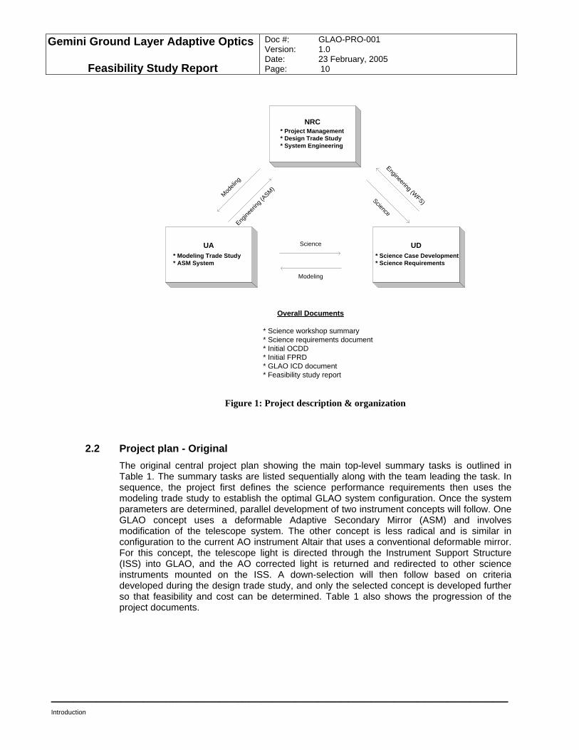
The interrelationship between the teams and their contributions are illustrated in Figure 1, along with the feasibility study documents.
Gemini Ground Layer Adaptive Optics
Feasibility Study Report
Doc #: GLAO-PRO-001 Version: 1.0 Date: 23 February, 2005 Page: 10
____________________________________________________________
Introduction
Overall Documents
* Science workshop summary* Science requirements document* Initial OCDD* Initial FPRD* GLAO ICD document* Feasibility study report
NRC* Project Management* Design Trade Study* System Engineering
UA* Modeling Trade Study* ASM System
UD* Science Case Development* Science Requirements
Modeli
ng
Engine
ering
(ASM)
Engineering (WFS)Science
Science
Modeling
Figure 1: Project description & organization
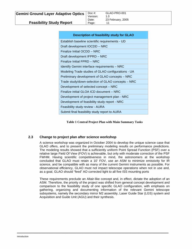
2.2 Project plan - Original The original central project plan showing the main top-level summary tasks is outlined in Table 1. The summary tasks are listed sequentially along with the team leading the task. In sequence, the project first defines the science performance requirements then uses the modeling trade study to establish the optimal GLAO system configuration. Once the system parameters are determined, parallel development of two instrument concepts will follow. One GLAO concept uses a deformable Adaptive Secondary Mirror (ASM) and involves modification of the telescope system. The other concept is less radical and is similar in configuration to the current AO instrument Altair that uses a conventional deformable mirror. For this concept, the telescope light is directed through the Instrument Support Structure (ISS) into GLAO, and the AO corrected light is returned and redirected to other science instruments mounted on the ISS. A down-selection will then follow based on criteria developed during the design trade study, and only the selected concept is developed further so that feasibility and cost can be determined. Table 1 also shows the progression of the project documents.
Gemini Ground Layer Adaptive Optics
Feasibility Study Report
Doc #: GLAO-PRO-001 Version: 1.0 Date: 23 February, 2005 Page: 11
____________________________________________________________
Introduction
Description of feasibility study for GLAO
Establish baseline scientific requirements - UD Draft development IOCDD – NRC Finalize Initial OCDD – NRC Draft development IFPRD – NRC Finalize Initial FPRD – NRC Identify Gemini interface requirements – NRC Modeling Trade studies of GLAO configurations - UA Preliminary development of GLAO concepts – NRC Trade study/down-selection of GLAO concepts – NRC Development of selected concept – NRC Finalize initial GLOA ICD document – NRC Development of project management plan - NRC Development of feasibility study report - NRC Feasibility study review - AURA Submit final feasibility study report to AURA
Table 1 Central Project Plan with Main Summary Tasks
2.3 Change to project plan after science workshop A science workshop was organized in October 2004 to develop the unique science case that GLAO offers, and to present the preliminary modeling results on performance predictions. The modeling results showed that a sufficiently uniform Point Spread Function (PSF) over a relative large Field Of View (FOV) is achievable, but only with moderate correction of the PSF FWHM. Having scientific competitiveness in mind, the astronomers at the workshop concluded that GLAO must retain a 10’ FOV, use an ASM to minimize emissivity for IR science, and be compatible with as many of the current Gemini instruments as possible. For observational efficiency, GLAO must not impact telescope operations when not in use and, as a goal, GLAO should “feed” AO corrected light to all five ISS mounting ports These requirements preclude an Altair-like concept and, in effect, dictate the adoption of an ASM. Therefore, the priority of the project was shifted from general concept development and comparison to the feasibility study of one specific GLAO configuration, with emphasis on gathering, organizing and documenting information of the relevant Gemini telescope subsystems, namely the secondary mirror M2 assembly, Laser Guide Star (LGS) system and Acquisition and Guide Unit (AGU) and their synthesis.
Gemini Ground Layer Adaptive Optics
Feasibility Study Report
Doc #: GLAO-PRO-001 Version: 1.0 Date: 23 February, 2005 Page: 12
____________________________________________________________
Introduction
2.4 GLAO Phased Development Plan To minimize the risk and cost of implementing and upgrading GLAO on Gemini, we propose a four-phase development and implementation plan based on suggestions made by the science team.
1) ASM without GLAO WFS or LGS: An ASM can be installed and tested without the GLAO WFS sending it signals. This development phase has a potentially short duration; once the ASM has been installed, tested and functions with the Gemini instrument suite, the next step can be implemented. If delays occur, the ASM can potentially be operated to give high Strehl AO corrections in the Mid-Infrared.
2) GLAO feeding existing instruments: GLAO can improve the performance of a number of existing Gemini instruments including GMOS and Flamingos 2.
3) GLAO specific instruments: Concepts for two GLAO instruments came out of the Aspen Meeting on second generation instruments. A wide field NIR imager2 and a GLAO d-IFU spectrograph will deliver the full science case (Appendix B).
4) Multi-Object AO: The ASM (and indeed the GLAO WFS system) can act as the first stage of a Multi-Object AO system. The ASM could act as a “woofer” which could take out the large scale atmospheric phase errors, leaving the small high-frequency phase errors to be dealt with by additional DMs built into the d-IFUs.
2.5 Organization of feasibility report This feasibility report is organized in sections in an order similar to the tasks list in Table 2. The science case and science requirements, Initial Operation Concept Definition Document (IOCDD), and Initial Functional and Performance Requirements Document (IFPRD) are described and summarized in the next three sections. The Modeling Trade Study section describes the effects AO parameters have on the overall GLAO performance and specifically discusses the scientific performance with respect to the science requirements. The trade study results are derived from two modeling techniques based either on analytic derivations or Monte Carlo (MC) simulations. The final GLAO configuration is analyzed in detail with a MC simulation and the results are documented in the same section. The Design Trade Study section discusses the design choices for the three major GLAO subsystems (LGS, WaveFront Sensing and ASM) and their impacts on the current telescope system. The final GLAO system proposed is also summarized. The relevant interfaces with the Gemini telescope are discussed in the next section. The Modification Requirements section outlines the expected changes to the telescope in order to accommodate the proposed GLAO system. The cost and schedule estimates to implement the GLAO system are outlined in the Project Plan section. And finally, the last section summarizes the feasibility study. All of the GLAO study related documents and reports are included as appendices.
2 An initial study of a potential wide field imager by INO is attached in Appendix H.
Gemini Ground Layer Adaptive Optics
Feasibility Study Report
Doc #: GLAO-PRO-001 Version: 1.0 Date: 23 February, 2005 Page: 13
____________________________________________________________
Introduction
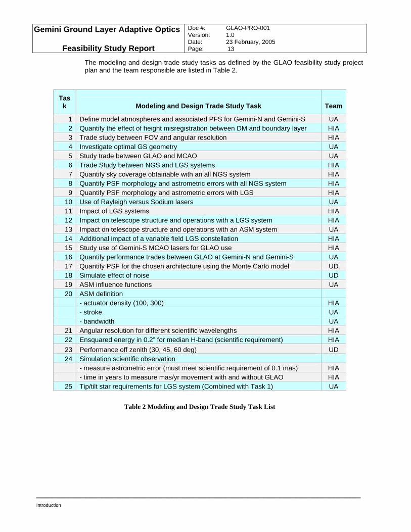
The modeling and design trade study tasks as defined by the GLAO feasibility study project plan and the team responsible are listed in Table 2.
Task Modeling and Design Trade Study Task Team
1 Define model atmospheres and associated PFS for Gemini-N and Gemini-S UA 2 Quantify the effect of height misregistration between DM and boundary layer HIA 3 Trade study between FOV and angular resolution HIA 4 Investigate optimal GS geometry UA 5 Study trade between GLAO and MCAO UA 6 Trade Study between NGS and LGS systems HIA 7 Quantify sky coverage obtainable with an all NGS system HIA 8 Quantify PSF morphology and astrometric errors with all NGS system HIA 9 Quantify PSF morphology and astrometric errors with LGS HIA
10 Use of Rayleigh versus Sodium lasers UA 11 Impact of LGS systems HIA 12 Impact on telescope structure and operations with a LGS system HIA 13 Impact on telescope structure and operations with an ASM system UA 14 Additional impact of a variable field LGS constellation HIA 15 Study use of Gemini-S MCAO lasers for GLAO use HIA 16 Quantify performance trades between GLAO at Gemini-N and Gemini-S UA 17 Quantify PSF for the chosen architecture using the Monte Carlo model UD 18 Simulate effect of noise UD 19 ASM influence functions UA 20 ASM definition
- actuator density (100, 300) HIA - stroke UA - bandwidth UA
21 Angular resolution for different scientific wavelengths HIA 22 Ensquared energy in 0.2” for median H-band (scientific requirement) HIA 23 Performance off zenith (30, 45, 60 deg) UD 24 Simulation scientific observation
- measure astrometric error (must meet scientific requirement of 0.1 mas) HIA - time in years to measure mas/yr movement with and without GLAO HIA
25 Tip/tilt star requirements for LGS system (Combined with Task 1) UA
Table 2 Modeling and Design Trade Study Task List
Gemini Ground Layer Adaptive Optics
Feasibility Study Report
Doc #: GLAO-PRO-001 Version: 1.0 Date: 23 February, 2005 Page: 14
____________________________________________________________
Science case development
3.0 Science case development
A key component of the GLAO feasibility study was to further develop the science case given in the document “Scientific Horizons at the Gemini Observatory: Exploring a Universe of Matter, Energy and Life” which came out of the Aspen meeting. The three groups who are collaborating on this study already had identified science teams to work on this aspect, and these teams were merged (with Simon Morris at the University of Durham acting as coordinator). All instrumentation science cases have to be developed in an iterative manner, with astronomers’ wish lists being compared with computer models for instrument performance and the hard reality of metal and glass. The innovative nature of the proposed AO system has made such iterations particularly necessary, while the relatively short timescale for the study has reduced the number of iterations that were possible. A workshop to develop the science case was held Oct 2-4 in Tucson. The timing was carefully chosen so that, at least preliminary, modeling results for GLAO performance were available, but also so that the results of the workshop could be used to guide the instrument design.
3.1 Objectives of science workshop The science workshop was meant to generate a science case document showing the gains from GLAO. Where possible, quantitative measures such as changes in required exposure times or improvements in measurement accuracies were to be computed. An additional goal was to discuss the GLAO implementation and investigate whether a partial GLAO implementation was scientifically useful. Finally, the workshop was meant to generate a set of science requirements based on the science cases which would be used by the engineering team.
3.2 Summary of science workshop The workshop successfully delivered on the above goals. The full science case is included in Appendix B to this feasibility report. The executive summary is included here: “The science case for a Ground Layer Adaptive Optics System for Gemini has to demonstrate that substantial gains can be made over both the no-AO situation, and also any already funded Gemini AO facilities. We do this by quantifying the shortening of exposure times and improvements of measured science parameters for a range of science cases. We focus on the ‘First Light’ science identified by the Aspen process, along with the gains in the study of stellar properties in our galaxy, but also include a range of other science cases to illustrate the wide range of applications which would benefit from GLAO. This list is far from exhaustive, as every non-diffraction limited Gemini observing proposal can benefit from GLAO. Better image quality delivered by GLAO will translate directly into shorter exposure times and more science.
Gemini Ground Layer Adaptive Optics
Feasibility Study Report
Doc #: GLAO-PRO-001 Version: 1.0 Date: 23 February, 2005 Page: 15
____________________________________________________________
Science case development
The Adaptive Secondary Mirror (ASM) will enable high Strehl ratio mid-infrared observations. GLAO will drastically alter the observing condition constraints of Gemini; image quality conditions which occur only 20% of the time now will occur 60-80% of the time when GLAO is operating. High priority observations that sometimes are not observed currently because of image quality constraints will be observed with GLAO. This improvement in image quality statistics will make scheduling programs easier and increase the operational efficiency of the observatory. With the phased development of GLAO described below, we also feel that GLAO can be delivered in a staged manner, greatly reducing the risk, while delivering exciting science at each stage.”
Gemini Ground Layer Adaptive Optics
Feasibility Study Report
Doc #: GLAO-PRO-001 Version: 1.0 Date: 23 February, 2005 Page: 16
____________________________________________________________
Science requirements
4.0 Science requirements
The science requirements of GLAO are listed in the Initial Operation Concept Definition Document attached in Appendix C. For convenience, these have been copied into the science case document and are also reproduced below.
4.1.1 Science Requirements
4.1.1.1 Background
The science requirements are obviously based around both the GLAO facility and also its instruments. The ‘ultimate’ instrument suite based on the Aspen process was that described to the GSC in Oct 2003. I.e. a GLAO NIR Imager, assumed to be like GSAOI with 0.15” sampling, 0.6-2.5µm coverage and a 10’ FOV (including a tunable filter with R>3000), along with the GLAO NIR spectrometer with 15-25 dIFUs, 0.2” sampling, 0.6-2.5µm coverage and a 10’ patrol field. The high-pole science cases for GLAO identified by the GSC and the Aspen process were:
• First light objects in the universe
• Dark matter on galactic scales
• Proper motion studies across the local group From these, one can derive the top level science requirements which are: For first light science, maximizing S/N in an IFU spatial element from an object with size typical of high redshift Lyman α emitter, combined with achieving a substantial multiplex gain. For the galactic science, maximizing astrometric accuracy in crowded and/or confused fields. The goal is to measure 0.3 mas motion over 5 years (200 km/s at M31). These were approximately translated into the requirements in the GLAO Announcement of Opportunity, but have been modified and supplemented. This process of converting the requirements into instrument specifications is non-trivial. For example, for astrometric accuracy, there was debate about whether it is better to improve image FWHM or to demand that a small but detectable ‘diffraction-limited’ core appears on top of each PSF? This led to a need for modeling which is part of the feasibility study.
4.1.1.2 Requirements
The science requirements are given for the GLAO facility, and do not include any instrument contribution. Obviously there will be resulting science requirements for any instrument behind the GLAO system which probably can be summarized as ‘Do not degrade the scientific performance of the GLAO facility’. In the absence of real instrument designs, this seems the only practical approach, but as a result some additional contingency (i.e. harsher requirements) may be needed to give the instrument designers room for manoeuvre.
Gemini Ground Layer Adaptive Optics
Feasibility Study Report
Doc #: GLAO-PRO-001 Version: 1.0 Date: 23 February, 2005 Page: 17
____________________________________________________________
Science requirements
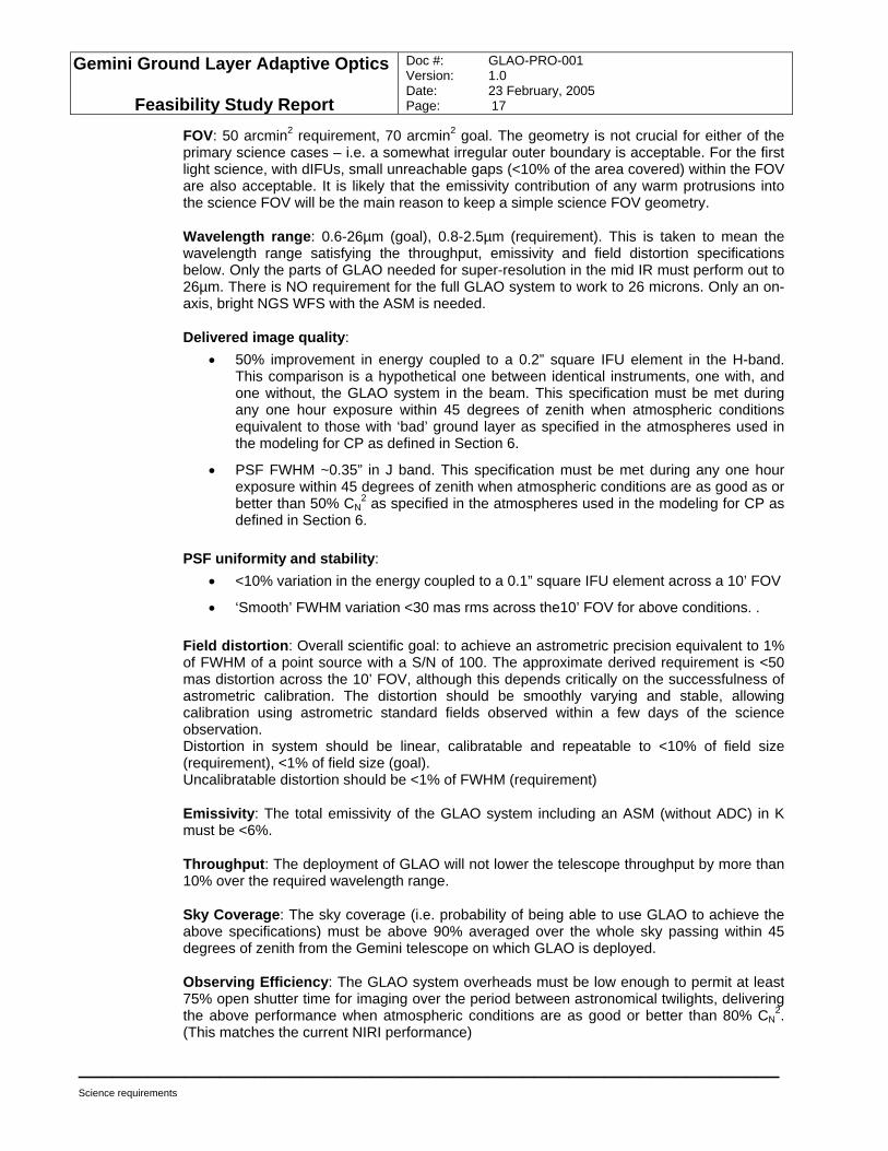
FOV: 50 arcmin2 requirement, 70 arcmin2 goal. The geometry is not crucial for either of the primary science cases – i.e. a somewhat irregular outer boundary is acceptable. For the first light science, with dIFUs, small unreachable gaps (<10% of the area covered) within the FOV are also acceptable. It is likely that the emissivity contribution of any warm protrusions into the science FOV will be the main reason to keep a simple science FOV geometry. Wavelength range: 0.6-26µm (goal), 0.8-2.5µm (requirement). This is taken to mean the wavelength range satisfying the throughput, emissivity and field distortion specifications below. Only the parts of GLAO needed for super-resolution in the mid IR must perform out to 26µm. There is NO requirement for the full GLAO system to work to 26 microns. Only an on-axis, bright NGS WFS with the ASM is needed. Delivered image quality:
• 50% improvement in energy coupled to a 0.2” square IFU element in the H-band. This comparison is a hypothetical one between identical instruments, one with, and one without, the GLAO system in the beam. This specification must be met during any one hour exposure within 45 degrees of zenith when atmospheric conditions equivalent to those with ‘bad’ ground layer as specified in the atmospheres used in the modeling for CP as defined in Section 6.
• PSF FWHM ~0.35” in J band. This specification must be met during any one hour exposure within 45 degrees of zenith when atmospheric conditions are as good as or better than 50% CN
2 as specified in the atmospheres used in the modeling for CP as defined in Section 6.
PSF uniformity and stability:
• <10% variation in the energy coupled to a 0.1” square IFU element across a 10’ FOV
• ‘Smooth’ FWHM variation <30 mas rms across the10’ FOV for above conditions. . Field distortion: Overall scientific goal: to achieve an astrometric precision equivalent to 1% of FWHM of a point source with a S/N of 100. The approximate derived requirement is <50 mas distortion across the 10’ FOV, although this depends critically on the successfulness of astrometric calibration. The distortion should be smoothly varying and stable, allowing calibration using astrometric standard fields observed within a few days of the science observation. Distortion in system should be linear, calibratable and repeatable to <10% of field size (requirement), <1% of field size (goal). Uncalibratable distortion should be <1% of FWHM (requirement) Emissivity: The total emissivity of the GLAO system including an ASM (without ADC) in K must be <6%. Throughput: The deployment of GLAO will not lower the telescope throughput by more than 10% over the required wavelength range. Sky Coverage: The sky coverage (i.e. probability of being able to use GLAO to achieve the above specifications) must be above 90% averaged over the whole sky passing within 45 degrees of zenith from the Gemini telescope on which GLAO is deployed. Observing Efficiency: The GLAO system overheads must be low enough to permit at least 75% open shutter time for imaging over the period between astronomical twilights, delivering the above performance when atmospheric conditions are as good or better than 80% CN
2. (This matches the current NIRI performance)
Gemini Ground Layer Adaptive Optics
Feasibility Study Report
Doc #: GLAO-PRO-001 Version: 1.0 Date: 23 February, 2005 Page: 18
____________________________________________________________
Science requirements
Other Instruments: For the ASM solution, the GLAO system needs to allow all instruments to operate. Instruments benefiting from the full GLAO correction are GMOS and Flamingos 2. A high Strehl feed for the MIR instruments T-ReCS or MICHELLE is desirable which may require a different WFS solution. Chopping and Dithering: Requirement on dithering for closed loop AO NIR – 5 arcsec. MIR needs chopping of 30 arcsec.
4.1.2 IOCDD Additional Material The IOCDD also identifies the key operational scenarios, outlines observation procedures, and describes the required interactions between GLAO and the telescope system. In order to do this, five observing scenarios are discussed exploring a range of GLAO observations, and indeed also describing how non-GLAO observations can be taken during the proposed phased development of the GLAO facility.
Gemini Ground Layer Adaptive Optics
Feasibility Study Report
Doc #: GLAO-PRO-001 Version: 1.0 Date: 23 February, 2005 Page: 19
____________________________________________________________
Functional requirements
5.0 Functional requirements
For the GLAO system, the functional requirements originated from three sources:
• As derived from the science requirements
• As dictated by the astronomers at the science workshop
• As set by the Gemini General Interface Control Documents (ICDs) and established standard
Based on the first and second sources, the top-level GLAO functionality must:
• Incorporate an ASM system that provides high bandwidth AO correction, low bandwidth X-Y, tip-tilt and focus compensations, and support current chopping and dithering operation
• Utilize a guide star system with both LGS and Natural Guide Star (NGS) for sky coverage and PSF uniformity considerations
• Provide backward compatibility with the current Gemini instruments
• Provide backward compatibility with all aspects of telescope operation, e.g. pointing and guiding, calibration and mirror figuring etc.
• Support both AO and non-AO observations
• Feed AO corrected light to all five ISS mounting ports The third source provides functional requirements with regards to environmental conditions, handling equipment and procedure. The detailed functional and performance requirements for the GLAO system are described in the IFPRD document attached in Appendix D.
Gemini Ground Layer Adaptive Optics
Feasibility Study Report
Doc #: GLAO-PRO-001 Version: 1.0 Date: 23 February, 2005 Page: 20
____________________________________________________________
Modeling trade study
6.0 Modeling trade study
The investigation of performance trades for Gemini GLAO has relied heavily on numerical modeling, for want of any operational GLAO system at a telescope, and the impracticality of adequate tests on the optics bench. We describe in this section the modeling tools used, including the atmospheric Cn
2 profiles, and the results of investigations into the key issues of guide star type and geometry, DM height conjugation and actuator count, and PSF resolution and uniformity versus demanded field of view. The goal of these studies was to identify GLAO system architectures that would satisfy the science requirements.
6.1 GLAO performance modeling tools
6.1.1 Model Cn2 profiles
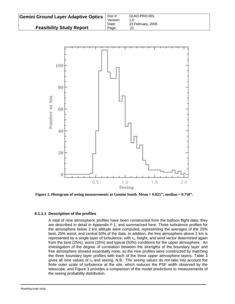
GLAO system performance depends crucially on the structure of the atmospheric turbulence profile. In particular, the size of the compensated field and the uniformity of the delivered PSF over the field depend on the thickness of the boundary layer, while the overall degree of image improvement depends sensitively on the ratio of aberration in the boundary layer to that in the free atmosphere. Unfortunately for the present study, these are not quantities that have been studied in detail at any site, because prior to the emergence of GLAO as a potentially valuable observing tool, they were not seen as important measures of a site’s quality. It is fortunate, on the other hand, that the only detailed measurements made on the structure of the atmospheric turbulence in the boundary layer at any site were recorded from balloon flights during the Gemini-S seeing campaign. The atmospheric turbulence profiles used in this study have been derived from those data. The profiles therefore reflect conditions above Cerro Pachón (Figure 2). While the seeing at Mauna Kea is consistently slightly better, and in particular the boundary layer is believed to be on average less severe, there has as yet been no long-term study to quantify the strength and vertical structure of the low level turbulence. It is therefore not possible at this stage to construct models of the Cn
2 profile above Mauna Kea that can distinguish differences in GLAO performance at the two sites.
Gemini Ground Layer Adaptive Optics
Feasibility Study Report
Doc #: GLAO-PRO-001 Version: 1.0 Date: 23 February, 2005 Page: 21
____________________________________________________________
Modeling trade study
Figure 2. Histogram of seeing measurements at Gemini South. Mean = 0.825”; median = 0.758”.
6.1.1.1 Description of the profiles
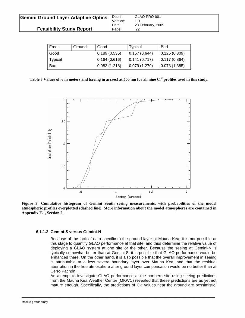
A total of nine atmospheric profiles have been constructed from the balloon flight data; they are described in detail in Appendix F.1, and summarized here. Three turbulence profiles for the atmosphere below 2 km altitude were computed, representing the averages of the 25% best, 25% worst, and central 50% of the data. In addition, the free atmosphere above 2 km is represented by a single layer of turbulence, with r0, height, and wind vector determined again from the best (25%), worst (25%) and typical (50%) conditions for the upper atmosphere. An investigation of the degree of correlation between the strengths of the boundary layer and free atmosphere showed essentially none, so the nine profiles were constructed by matching the three boundary layer profiles with each of the three upper atmosphere layers. Table 3 gives all nine values of r0 and seeing. N.B.: The seeing values do not take into account the finite outer scale of turbulence at the site, which reduces the PSF width observed by the telescope, and Figure 3 provides a comparison of the model predictions to measurements of the seeing probability distribution.
Gemini Ground Layer Adaptive Optics
Feasibility Study Report
Doc #: GLAO-PRO-001 Version: 1.0 Date: 23 February, 2005 Page: 22
____________________________________________________________
Modeling trade study
Free: Ground: Good Typical Bad Good 0.189 (0.535) 0.157 (0.644) 0.125 (0.809) Typical 0.164 (0.616) 0.141 (0.717) 0.117 (0.864) Bad 0.083 (1.218) 0.079 (1.279) 0.073 (1.385)
Table 3 Values of r0 in meters and (seeing in arcsec) at 500 nm for all nine Cn2 profiles used in this study.
Figure 3. Cumulative histogram of Gemini South seeing measurements, with probabilities of the model atmospheric profiles overplotted (dashed line). More information about the model atmospheres are contained in Appendix F.1, Section 2.
6.1.1.2 Gemini-S versus Gemini-N
Because of the lack of data specific to the ground layer at Mauna Kea, it is not possible at this stage to quantify GLAO performance at that site, and thus determine the relative value of deploying a GLAO system at one site or the other. Because the seeing at Gemini-N is typically somewhat better than at Gemini-S, it is possible that GLAO performance would be enhanced there. On the other hand, it is also possible that the overall improvement in seeing is attributable to a less severe boundary layer over Mauna Kea, and that the residual aberration in the free atmosphere after ground layer compensation would be no better than at Cerro Pachón. An attempt to investigate GLAO performance at the northern site using seeing predictions from the Mauna Kea Weather Center (MKWC) revealed that these predictions are as yet not mature enough. Specifically, the predictions of Cn
2 values near the ground are pessimistic,
Gemini Ground Layer Adaptive Optics
Feasibility Study Report
Doc #: GLAO-PRO-001 Version: 1.0 Date: 23 February, 2005 Page: 23
____________________________________________________________
Modeling trade study
leading to larger seeing values than are actually observed at Mauna Kea telescopes. According to MKWC personnel, this is because of an inadequate model of the interaction of the boundary layer air with local topography. This is expected to be remedied in early 2005, with the predictions anchored against seeing monitor data, and when that occurs, it may be possible to use these numerical results to make meaningful estimates of GLAO performance at Gemini-N.
6.1.1.3 Model atmosphere and seeing comparisons to other observatories
As a check that the turbulence profiles derived for Cerro Pachón were not out of line when compared to those from other sites, we have simulated the performance of GLAO also for the profile adopted for the feasibility study of ESO’s Hawk-I system on Cerro Paranal. The results, presented in Table 4 below, show that the predictions for Paranal are bracketed by those for a number of profiles adopted for Pachón and so give confidence in the modeling.
Paranal Good-Good Typical-Typical Bad-Bad Wavelength (microns) GLAO No AO GLAO No AO GLAO No AO GLAO No AO 0.7 0.559 0.688 0.296 0.387 0.447 0.519 0.894 1.075 1.0 0.461 0.616 0.238 0.343 0.379 0.463 0.754 0.970 1.65 0.320 0.519 0.176 0.281 0.284 0.385 0.544 0.829 2.2 0.251 0.464 0.150 0.247 0.236 0.342 0.430 0.750
Table 4 FHWM of on-axis corrected and uncorrected images in arcsec for the Hawk-I Cerro Paranal atmosphere and three of the Cerro Pachón profiles.
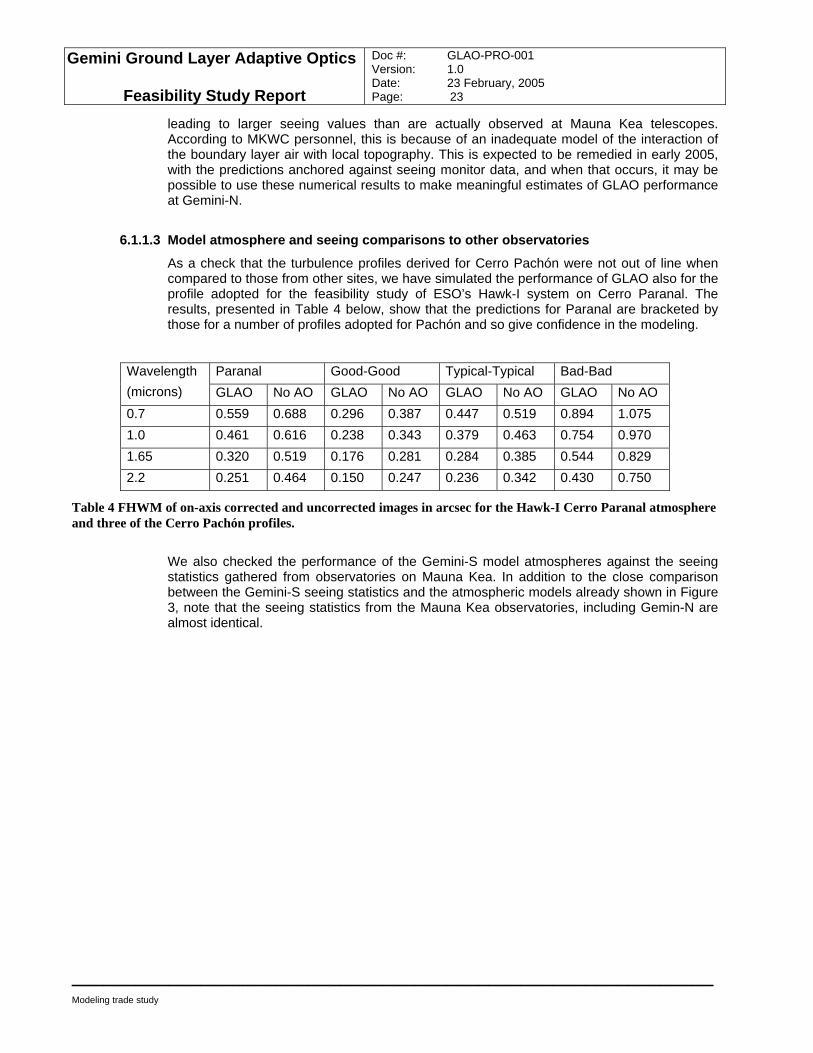
We also checked the performance of the Gemini-S model atmospheres against the seeing statistics gathered from observatories on Mauna Kea. In addition to the close comparison between the Gemini-S seeing statistics and the atmospheric models already shown in Figure 3, note that the seeing statistics from the Mauna Kea observatories, including Gemin-N are almost identical.
Gemini Ground Layer Adaptive Optics
Feasibility Study Report
Doc #: GLAO-PRO-001 Version: 1.0 Date: 23 February, 2005 Page: 24
____________________________________________________________
Modeling trade study
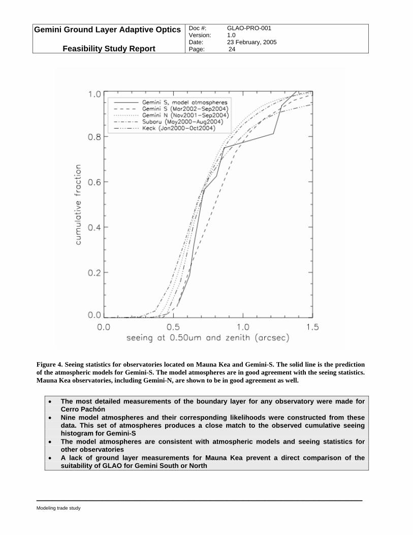
Figure 4. Seeing statistics for observatories located on Mauna Kea and Gemini-S. The solid line is the prediction of the atmospheric models for Gemini-S. The model atmospheres are in good agreement with the seeing statistics. Mauna Kea observatories, including Gemini-N, are shown to be in good agreement as well.
• The most detailed measurements of the boundary layer for any observatory were made for
Cerro Pachón • Nine model atmospheres and their corresponding likelihoods were constructed from these
data. This set of atmospheres produces a close match to the observed cumulative seeing histogram for Gemini-S
• The model atmospheres are consistent with atmospheric models and seeing statistics for other observatories
• A lack of ground layer measurements for Mauna Kea prevent a direct comparison of the suitability of GLAO for Gemini South or North
Gemini Ground Layer Adaptive Optics
Feasibility Study Report
Doc #: GLAO-PRO-001 Version: 1.0 Date: 23 February, 2005 Page: 25
____________________________________________________________
Modeling trade study
6.1.2 Validation of the modeling tools In assessing the viability of GLAO on Gemini, simulation codes written by all three participating groups have been used, in an effort to parallelize the work. To ensure a high degree of confidence in the performance of these codes, they and two additional codes have been tested against each other. A full account of the comparisons is given in Appendices F.1 and F.2. Two codes are full Monte Carlo simulations, while the remaining three implement analytic calculations. Starting from the same inputs, three figures of merit were computed for PSFs compensated with GLAO: FWHM, enclosed energy in a 0.1” square, and Strehl ratio. (Of these, the Strehl ratio, which is not expected to be high in this partially corrected regime, is the least valuable. At the test wavelength of 1.25 µm, all the codes predictions fall within ~1 %.) Three Cn
2 profiles were run both with and without photon and read noise included. In all models, spatial fitting error was included, and some included WFS aliasing error. Other sources of residual wavefront error, such as servo lag, were omitted. The intention was not to produce realistic estimates of performance at Gemini, but merely to verify that the codes all predicted essentially the same level of performance. In summary, the codes were found to agree well in the FWHM and ensquared energy, with the analytic codes predicting slightly better performance than the Monte Carlo models. This is likely to be because of the inclusion in the latter of a greater range of physical effects.
• Monte Carlo and Analytic Codes from the different groups yield comparable results • Analytic codes predict slightly better performance than Monte Carlo Codes probably because
Monte Carlo codes include more physical effects.
6.2 Optimal guide star parameters There are several parameters related to the choice of guide stars that affect the overall performance of a GLAO system. One factor is the optimal guide star geometry, while the other factors are related to the type of guide star from which to sense high order wavefront aberrations. In order of ascending cost, these include the choice of NGS or LGS, and finally a choice between Sodium resonance and Rayleigh beacons.
6.2.1 Optimal guide star geometry Using an analytic code, a range of guide star numbers and geometries have been investigated. In all cases NGS were assumed, which simplified the model and set aside the question of the relative placement of high-order beacons and tip-tilt beacons that must be addressed with LGS. Guided by the theoretical result of Tokovinin that the ideal beacon geometry for GLAO is a complete ring at the edge of the field of view, regular polygons, with and without an additional axial beacon, were explored from a triangle to a heptagon. For comparison, a single axial beacon was also investigated. The results, described in Appendix F.1, are here summarized in Table 5.
Gemini Ground Layer Adaptive Optics
Feasibility Study Report
Doc #: GLAO-PRO-001 Version: 1.0 Date: 23 February, 2005 Page: 26
____________________________________________________________
Modeling trade study
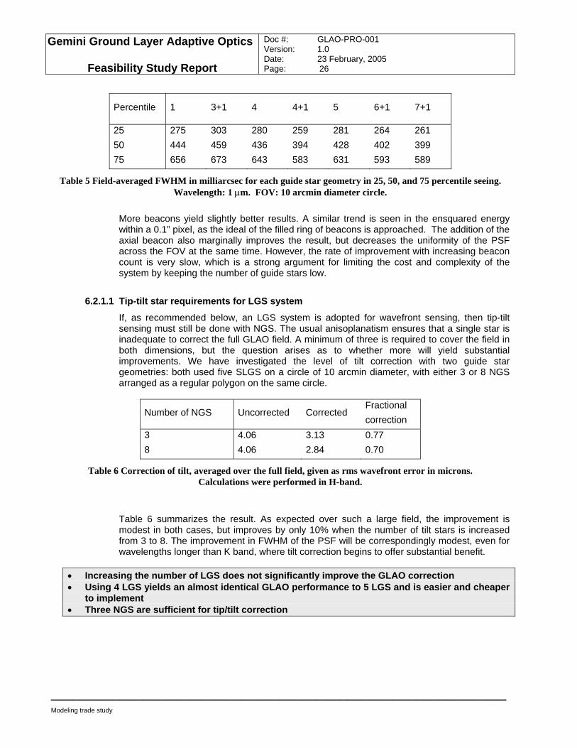
Percentile 1 3+1 4 4+1 5 6+1 7+1
25 275 303 280 259 281 264 261 50 444 459 436 394 428 402 399 75 656 673 643 583 631 593 589
Table 5 Field-averaged FWHM in milliarcsec for each guide star geometry in 25, 50, and 75 percentile seeing. Wavelength: 1 µm. FOV: 10 arcmin diameter circle.
More beacons yield slightly better results. A similar trend is seen in the ensquared energy within a 0.1” pixel, as the ideal of the filled ring of beacons is approached. The addition of the axial beacon also marginally improves the result, but decreases the uniformity of the PSF across the FOV at the same time. However, the rate of improvement with increasing beacon count is very slow, which is a strong argument for limiting the cost and complexity of the system by keeping the number of guide stars low.
6.2.1.1 Tip-tilt star requirements for LGS system
If, as recommended below, an LGS system is adopted for wavefront sensing, then tip-tilt sensing must still be done with NGS. The usual anisoplanatism ensures that a single star is inadequate to correct the full GLAO field. A minimum of three is required to cover the field in both dimensions, but the question arises as to whether more will yield substantial improvements. We have investigated the level of tilt correction with two guide star geometries: both used five SLGS on a circle of 10 arcmin diameter, with either 3 or 8 NGS arranged as a regular polygon on the same circle.
Number of NGS Uncorrected Corrected Fractional correction
3 4.06 3.13 0.77 8 4.06 2.84 0.70
Table 6 Correction of tilt, averaged over the full field, given as rms wavefront error in microns. Calculations were performed in H-band.
Table 6 summarizes the result. As expected over such a large field, the improvement is modest in both cases, but improves by only 10% when the number of tilt stars is increased from 3 to 8. The improvement in FWHM of the PSF will be correspondingly modest, even for wavelengths longer than K band, where tilt correction begins to offer substantial benefit.
• Increasing the number of LGS does not significantly improve the GLAO correction • Using 4 LGS yields an almost identical GLAO performance to 5 LGS and is easier and cheaper
to implement • Three NGS are sufficient for tip/tilt correction
Gemini Ground Layer Adaptive Optics
Feasibility Study Report
Doc #: GLAO-PRO-001 Version: 1.0 Date: 23 February, 2005 Page: 27
____________________________________________________________
Modeling trade study
6.2.2 Trade study between NGS and LGS systems We simulated both a LGS and a 3-star NGS GLAO system to determine if a NGS system could meet the Gemini GLAO scientific requirements. PSFs, equally spaced on a grid with 1 arcminute separation, were simulated analytically using PAOLA for both systems. We then performed a detailed morphological study of those PSFs. Full results of the study are presented in Appendix F.3. As discussed below, the all-NGS GLAO system failed to meet the scientific requirements.
6.2.2.1 Sky coverage obtainable with an all-NGS system
Initial studies of the sky coverage with an all-NGS GLAO system were promising. At the North Galactic Pole, 35% of the fields had 8 suitable NGSs with a total magnitude brighter than 12 within the 10 arcminute FOV. 90% of 10 arcminute fields had 8 suitable NGSs with a total magnitude brighter than 14. These results are mentioned in Appendix F.2. A deeper look into this issue was not required because subsequent studies showed that an all NGS GLAO system did not meet the uniformity system requirements.
6.2.2.2 PSF morphological variations with LGS and NGS systems
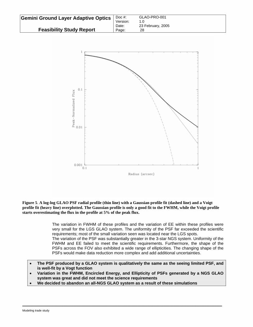
Variation in PSF morphology was readily apparent in the simulations described in Appendix F.3. Figure 5 shows that the shape of the GLAO PSF is well described by a Gaussian core component and a Lorentzian halo (overall, this profile is well-fit by the Vogt function). The shape of GLAO PSF is qualitatively the same as the natural seeing PSF.
Gemini Ground Layer Adaptive Optics
Feasibility Study Report
Doc #: GLAO-PRO-001 Version: 1.0 Date: 23 February, 2005 Page: 28
____________________________________________________________
Modeling trade study
Figure 5. A log-log GLAO PSF radial profile (thin line) with a Gaussian profile fit (dashed line) and a Voigt profile fit (heavy line) overplotted. The Gaussian profile is only a good fit to the FWHM, while the Voigt profile starts overestimating the flux in the profile at 5% of the peak flux.
The variation in FWHM of these profiles and the variation of EE within these profiles were very small for the LGS GLAO system. The uniformity of the PSF far exceeded the scientific requirements; most of the small variation seen was located near the LGS spots. The variation of the PSF was substantially greater in the 3-star NGS system. Uniformity of the FWHM and EE failed to meet the scientific requirements. Furthermore, the shape of the PSFs across the FOV also exhibited a wide range of ellipticities. The changing shape of the PSFs would make data reduction more complex and add additional uncertainties.
• The PSF produced by a GLAO system is qualitatively the same as the seeing limited PSF, and
is well-fit by a Vogt function • Variation in the FWHM, Encircled Energy, and Ellipticity of PSFs generated by a NGS GLAO
system was great and did not meet the science requirements • We decided to abandon an all-NGS GLAO system as a result of these simulations
Gemini Ground Layer Adaptive Optics
Feasibility Study Report
Doc #: GLAO-PRO-001 Version: 1.0 Date: 23 February, 2005 Page: 29
____________________________________________________________
Modeling trade study
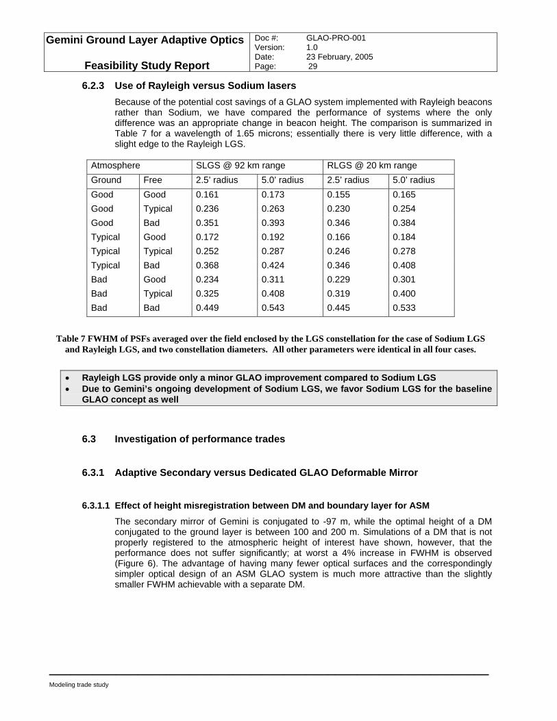
6.2.3 Use of Rayleigh versus Sodium lasers Because of the potential cost savings of a GLAO system implemented with Rayleigh beacons rather than Sodium, we have compared the performance of systems where the only difference was an appropriate change in beacon height. The comparison is summarized in Table 7 for a wavelength of 1.65 microns; essentially there is very little difference, with a slight edge to the Rayleigh LGS.
Atmosphere SLGS @ 92 km range RLGS @ 20 km range Ground Free 2.5’ radius 5.0’ radius 2.5’ radius 5.0’ radius Good Good 0.161 0.173 0.155 0.165 Good Typical 0.236 0.263 0.230 0.254 Good Bad 0.351 0.393 0.346 0.384 Typical Good 0.172 0.192 0.166 0.184 Typical Typical 0.252 0.287 0.246 0.278 Typical Bad 0.368 0.424 0.346 0.408 Bad Good 0.234 0.311 0.229 0.301 Bad Typical 0.325 0.408 0.319 0.400 Bad Bad 0.449 0.543 0.445 0.533
Table 7 FWHM of PSFs averaged over the field enclosed by the LGS constellation for the case of Sodium LGS and Rayleigh LGS, and two constellation diameters. All other parameters were identical in all four cases.
• Rayleigh LGS provide only a minor GLAO improvement compared to Sodium LGS • Due to Gemini’s ongoing development of Sodium LGS, we favor Sodium LGS for the baseline
GLAO concept as well
6.3 Investigation of performance trades
6.3.1 Adaptive Secondary versus Dedicated GLAO Deformable Mirror
6.3.1.1 Effect of height misregistration between DM and boundary layer for ASM
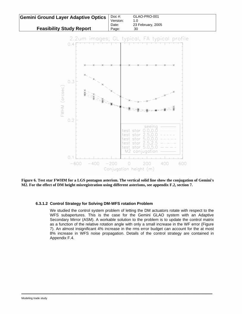
The secondary mirror of Gemini is conjugated to -97 m, while the optimal height of a DM conjugated to the ground layer is between 100 and 200 m. Simulations of a DM that is not properly registered to the atmospheric height of interest have shown, however, that the performance does not suffer significantly; at worst a 4% increase in FWHM is observed (Figure 6). The advantage of having many fewer optical surfaces and the correspondingly simpler optical design of an ASM GLAO system is much more attractive than the slightly smaller FWHM achievable with a separate DM.
Gemini Ground Layer Adaptive Optics
Feasibility Study Report
Doc #: GLAO-PRO-001 Version: 1.0 Date: 23 February, 2005 Page: 30
____________________________________________________________
Modeling trade study
Figure 6. Test star FWHM for a LGS pentagon asterism. The vertical solid line show the conjugation of Gemini's M2. For the effect of DM height misregistration using different asterisms, see appendix F.2, section 7.
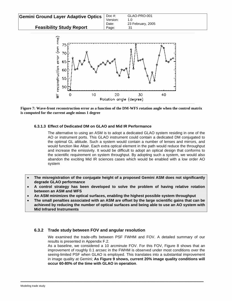
6.3.1.2 Control Strategy for Solving DM-WFS rotation Problem
We studied the control system problem of letting the DM actuators rotate with respect to the WFS subapertures. This is the case for the Gemini GLAO system with an Adaptive Secondary Mirror (ASM). A workable solution to the problem is to update the control matrix as a function of the relative rotation angle with only a small increase in the WF error (Figure 7). An almost insignificant 4% increase in the rms error budget can account for the at most 8% increase in WFS noise propagation. Details of the control strategy are contained in Appendix F.4.
Gemini Ground Layer Adaptive Optics
Feasibility Study Report
Doc #: GLAO-PRO-001 Version: 1.0 Date: 23 February, 2005 Page: 31
____________________________________________________________
Modeling trade study
Figure 7: Wave-front reconstruction error as a function of the DM-WFS rotation angle when the control matrix is computed for the current angle minus 1 degree
6.3.1.3 Effect of Dedicated DM on GLAO and Mid IR Performance
The alternative to using an ASM is to adopt a dedicated GLAO system residing in one of the AO or instrument ports. This GLAO instrument could contain a dedicated DM conjugated to the optimal GL altitude. Such a system would contain a number of lenses and mirrors, and would function like Altair. Each extra optical element in the path would reduce the throughput and increase the emissivity. It would be difficult to adopt an optical design that conforms to the scientific requirement on system throughput. By adopting such a system, we would also abandon the exciting Mid IR sciences cases which would be enabled with a low order AO system
• The misregistration of the conjugate height of a proposed Gemini ASM does not significantly
degrade GLAO performance • A control strategy has been developed to solve the problem of having relative rotation
between an ASM and WFS • An ASM minimizes the optical surfaces, enabling the highest possible system throughput • The small penalties associated with an ASM are offset by the large scientific gains that can be
achieved by reducing the number of optical surfaces and being able to use an AO system with Mid Infrared Instruments
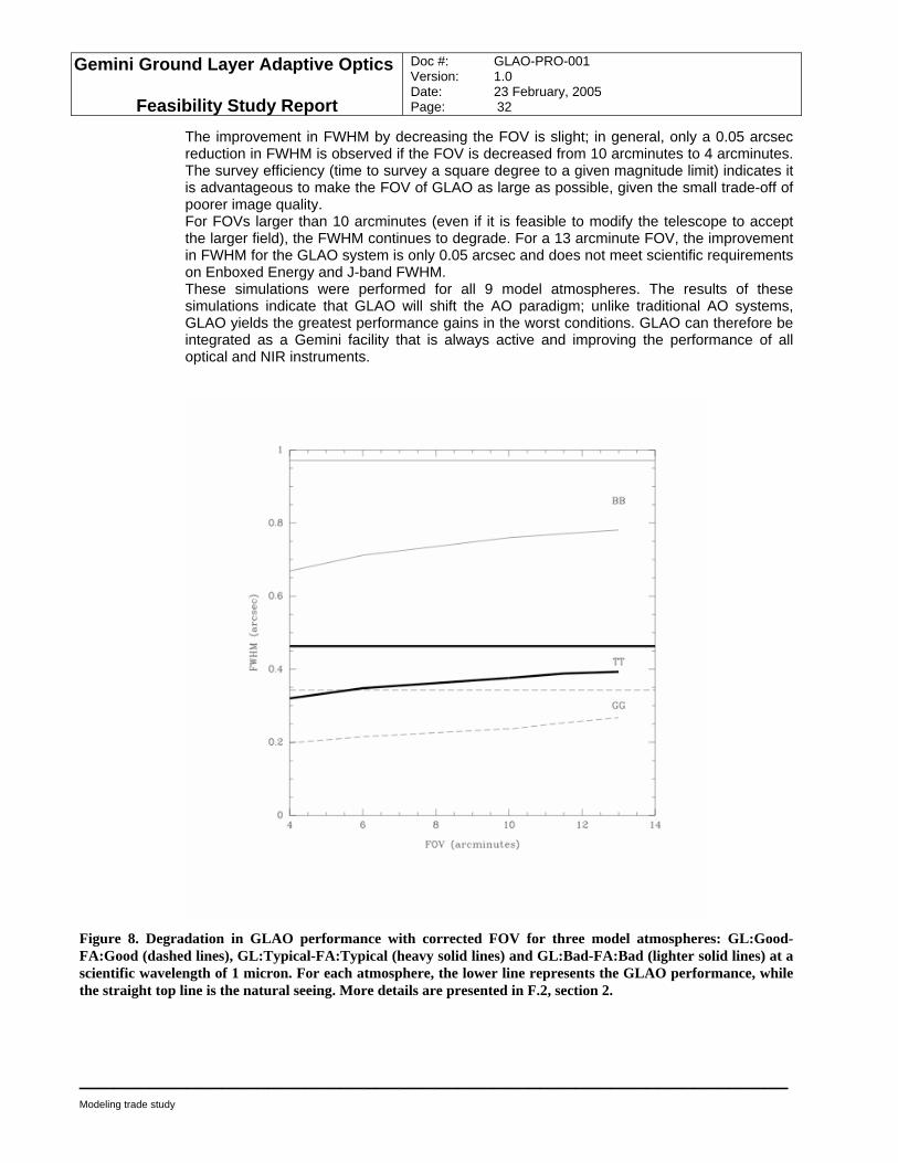
6.3.2 Trade study between FOV and angular resolution We examined the trade-offs between PSF FWHM and FOV. A detailed summary of our results is presented in Appendix F.2. As a baseline, we considered a 10 arcminute FOV. For this FOV, Figure 8 shows that an improvement of roughly 0.1 arcsec in the FWHM is observed under most conditions over the seeing-limited PSF when GLAO is employed. This translates into a substantial improvement in image quality at Gemini; As Figure 9 shows, current 20% image quality conditions will occur 60-80% of the time with GLAO in operation.
Gemini Ground Layer Adaptive Optics
Feasibility Study Report
Doc #: GLAO-PRO-001 Version: 1.0 Date: 23 February, 2005 Page: 32
____________________________________________________________
Modeling trade study
The improvement in FWHM by decreasing the FOV is slight; in general, only a 0.05 arcsec reduction in FWHM is observed if the FOV is decreased from 10 arcminutes to 4 arcminutes. The survey efficiency (time to survey a square degree to a given magnitude limit) indicates it is advantageous to make the FOV of GLAO as large as possible, given the small trade-off of poorer image quality. For FOVs larger than 10 arcminutes (even if it is feasible to modify the telescope to accept the larger field), the FWHM continues to degrade. For a 13 arcminute FOV, the improvement in FWHM for the GLAO system is only 0.05 arcsec and does not meet scientific requirements on Enboxed Energy and J-band FWHM. These simulations were performed for all 9 model atmospheres. The results of these simulations indicate that GLAO will shift the AO paradigm; unlike traditional AO systems, GLAO yields the greatest performance gains in the worst conditions. GLAO can therefore be integrated as a Gemini facility that is always active and improving the performance of all optical and NIR instruments.
Figure 8. Degradation in GLAO performance with corrected FOV for three model atmospheres: GL:Good-FA:Good (dashed lines), GL:Typical-FA:Typical (heavy solid lines) and GL:Bad-FA:Bad (lighter solid lines) at a scientific wavelength of 1 micron. For each atmosphere, the lower line represents the GLAO performance, while the straight top line is the natural seeing. More details are presented in F.2, section 2.
Gemini Ground Layer Adaptive Optics
Feasibility Study Report
Doc #: GLAO-PRO-001 Version: 1.0 Date: 23 February, 2005 Page: 33
____________________________________________________________
Modeling trade study
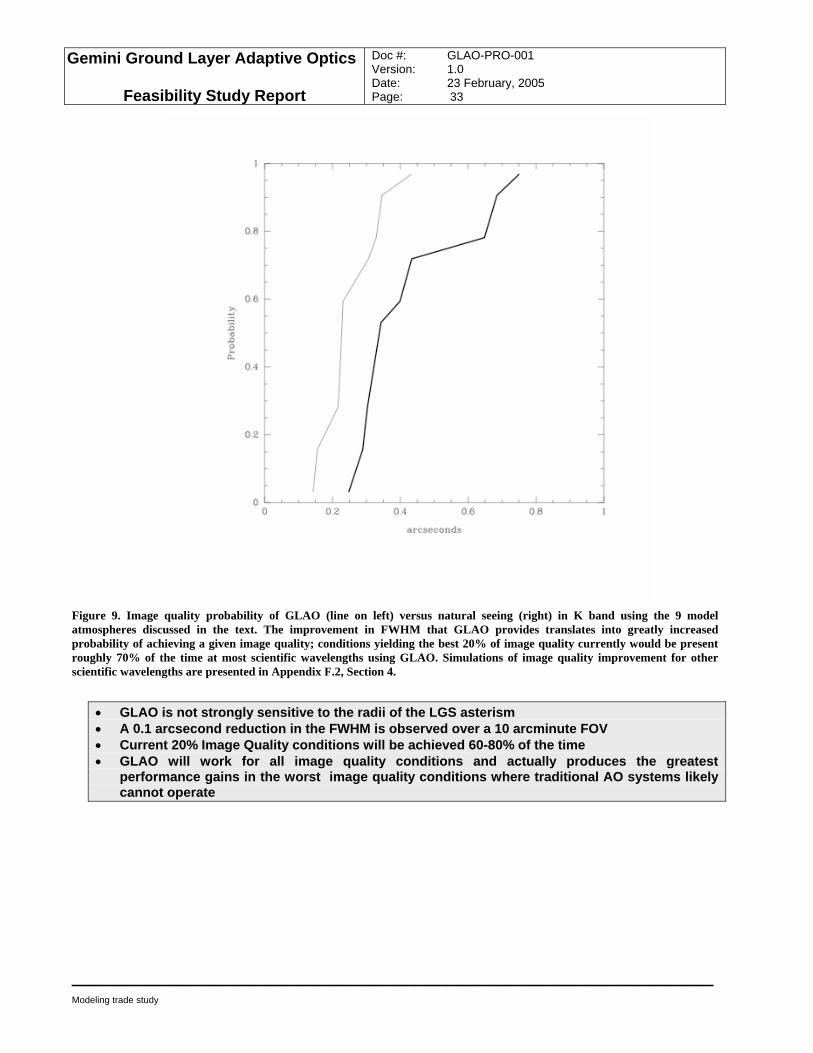
Figure 9. Image quality probability of GLAO (line on left) versus natural seeing (right) in K band using the 9 model atmospheres discussed in the text. The improvement in FWHM that GLAO provides translates into greatly increased probability of achieving a given image quality; conditions yielding the best 20% of image quality currently would be present roughly 70% of the time at most scientific wavelengths using GLAO. Simulations of image quality improvement for other scientific wavelengths are presented in Appendix F.2, Section 4.
• GLAO is not strongly sensitive to the radii of the LGS asterism • A 0.1 arcsecond reduction in the FWHM is observed over a 10 arcminute FOV • Current 20% Image Quality conditions will be achieved 60-80% of the time • GLAO will work for all image quality conditions and actually produces the greatest
performance gains in the worst image quality conditions where traditional AO systems likely cannot operate
Gemini Ground Layer Adaptive Optics
Feasibility Study Report
Doc #: GLAO-PRO-001 Version: 1.0 Date: 23 February, 2005 Page: 34
____________________________________________________________
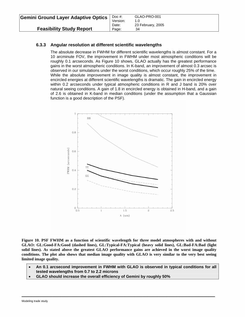
Modeling trade study
6.3.3 Angular resolution at different scientific wavelengths The absolute decrease in FWHM for different scientific wavelengths is almost constant. For a 10 arcminute FOV, the improvement in FWHM under most atmospheric conditions will be roughly 0.1 arcseconds. As Figure 10 shows, GLAO actually has the greatest performance gains in the worst atmospheric conditions. In K-band, an improvement of almost 0.3 arcsec is observed in our simulations under the worst conditions, which occur roughly 25% of the time. While the absolute improvement in image quality is almost constant, the improvement in encircled energies at different scientific wavelengths is dramatic. The gain in encircled energy within 0.2 arcseconds under typical atmospheric conditions in R and J band is 20% over natural seeing conditions. A gain of 1.8 in encircled energy is obtained in H-band, and a gain of 2.6 is obtained in K-band in median conditions (under the assumption that a Gaussian function is a good description of the PSF).
Figure 10. PSF FWHM as a function of scientific wavelength for three model atmospheres with and without GLAO: GL:Good-FA:Good (dashed lines), GL:Typical-FA:Typical (heavy solid lines), GL:Bad-FA:Bad (light solid lines). As stated above the greatest GLAO performance gains are achieved in the worst image quality conditions. The plot also shows that median image quality with GLAO is very similar to the very best seeing limited image quality.
• An 0.1 arcsecond improvement in FWHM with GLAO is observed in typical conditions for all tested wavelengths from 0.7 to 2.2 microns
• GLAO should increase the overall efficiency of Gemini by roughly 50%
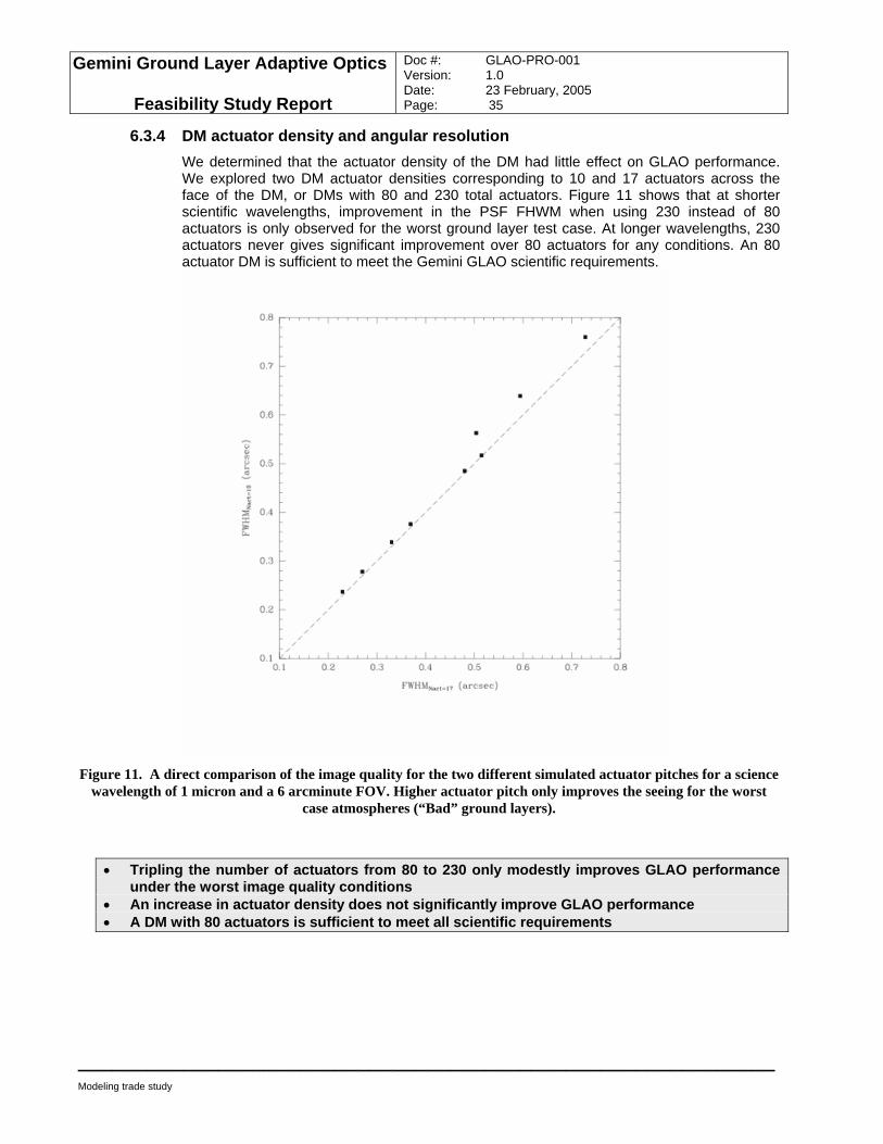
Gemini Ground Layer Adaptive Optics
Feasibility Study Report
Doc #: GLAO-PRO-001 Version: 1.0 Date: 23 February, 2005 Page: 35
____________________________________________________________
Modeling trade study
6.3.4 DM actuator density and angular resolution We determined that the actuator density of the DM had little effect on GLAO performance. We explored two DM actuator densities corresponding to 10 and 17 actuators across the face of the DM, or DMs with 80 and 230 total actuators. Figure 11 shows that at shorter scientific wavelengths, improvement in the PSF FHWM when using 230 instead of 80 actuators is only observed for the worst ground layer test case. At longer wavelengths, 230 actuators never gives significant improvement over 80 actuators for any conditions. An 80 actuator DM is sufficient to meet the Gemini GLAO scientific requirements.
Figure 11. A direct comparison of the image quality for the two different simulated actuator pitches for a science
wavelength of 1 micron and a 6 arcminute FOV. Higher actuator pitch only improves the seeing for the worst case atmospheres (“Bad” ground layers).
• Tripling the number of actuators from 80 to 230 only modestly improves GLAO performance under the worst image quality conditions
• An increase in actuator density does not significantly improve GLAO performance • A DM with 80 actuators is sufficient to meet all scientific requirements

Gemini Ground Layer Adaptive Optics
Feasibility Study Report
Doc #: GLAO-PRO-001 Version: 1.0 Date: 23 February, 2005 Page: 36
____________________________________________________________
Modeling trade study
6.4 Simulation of scientific performance We explored whether images produced from analytic PAOLA simulations of the Gemini LGS GLAO system fulfilled the scientific requirements. Specifically, we used these simulations to explore the uniformity of the PSF across the FOV and the improvement in encircled energy. The simulation was made in the J-band with an asterism of 5 LGS arranged in a pentagon around a circle with a diameter of 10 arcminutes. The complete study can be found in Appendix F.3.
6.4.1 Distortion of GLAO PSF One science requirement of a Gemini GLAO system is that the variation in FWHM must be less than 30 mas across the FOV. The simulated PSFs were actually much more stable; a variation of just 8 mas was observed across the 10 arcminute FOV. We have begun to examine the uniformity of the PSF when only 4 LGS are used. Initial results indicate that performance and PSF uniformity are not significantly worse than the results quoted here. We also showed that the encircled energy within a 0.2 arcsec aperture varied by just 3% across the FOV, which met another GLAO science requirement. A small distortion of the PSF was evident across the FOV. The mean ellipticity of PSFs across the FOV was 2%. This is highly correlated with the location of the LGS spots and should not vary frame to frame. It should be relatively easy to calibrate this small distortion out of images produced from the Gemini GLAO system.
6.4.2 Astrometric Error A properly determined GLAO astrometric error budget would require a much more sophisticated Monte Carlo simulation of both the opto-mechanics of the GLAO system and the atmosphere. Nevertheless, we used the variation in FWHM as a measure of the astrometric precision achievable with GLAO. This astrometric variation is actually less than the expected centering error of GLAO PSFs based on the rule of thumb that a centroid can be determined as accurately as 1% of the FWHM. A 3-sigma detection of a 3 mas/yr movement will require roughly 2.2 years with GLAO using median seeing K-band data. And 4.5 years using median R-band data. It would take ~30% longer to achieve this precision without GLAO.
• Analytic simulations of GLAO performance indicate that PSF uniformity is high when LGS are employed and easily meets scientific requirements
• GLAO should deliver a large field of view with small distortions and deviations from uniformity which enables astrometric studies
6.5 Complementarity between GLAO and MCAO modes Natural break points in the GLAO corrected field arise as GLAO is compared to planned MCAO on Gemini-S. GLAO will address a field of 10 arcmin diameter. The ability to image such a large field in a single exposure will yield a more constant PSF and more efficient use of observing time than the ~100 individual Altair/NIRI frames required to cover the same field. The deployment of GLAO will complement the MCAO system, which will be operational before GLAO comes on line. For detailed morphological studies, the higher resolution of MCAO will always be superior to GLAO. Nevertheless, it will require >50 MCAO pointings to
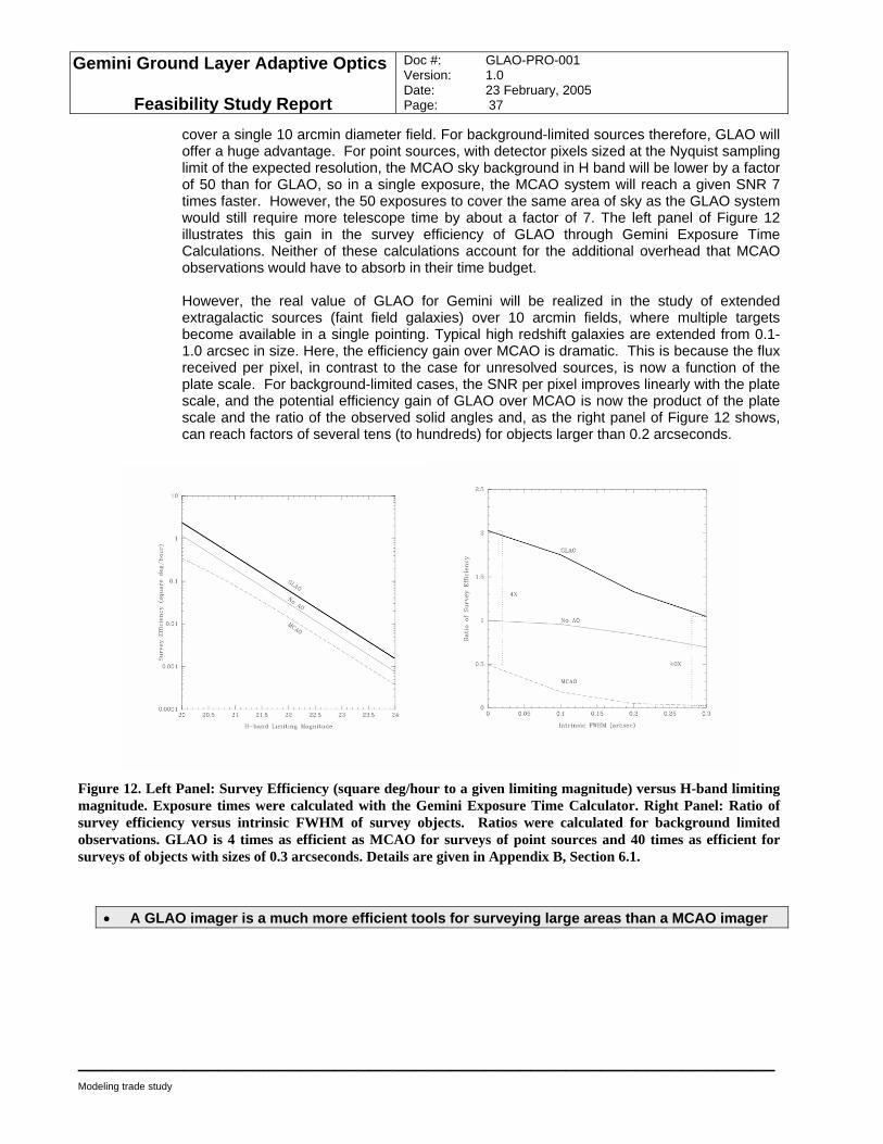
Gemini Ground Layer Adaptive Optics
Feasibility Study Report
Doc #: GLAO-PRO-001 Version: 1.0 Date: 23 February, 2005 Page: 37
____________________________________________________________
Modeling trade study
cover a single 10 arcmin diameter field. For background-limited sources therefore, GLAO will offer a huge advantage. For point sources, with detector pixels sized at the Nyquist sampling limit of the expected resolution, the MCAO sky background in H band will be lower by a factor of 50 than for GLAO, so in a single exposure, the MCAO system will reach a given SNR 7 times faster. However, the 50 exposures to cover the same area of sky as the GLAO system would still require more telescope time by about a factor of 7. The left panel of Figure 12 illustrates this gain in the survey efficiency of GLAO through Gemini Exposure Time Calculations. Neither of these calculations account for the additional overhead that MCAO observations would have to absorb in their time budget. However, the real value of GLAO for Gemini will be realized in the study of extended extragalactic sources (faint field galaxies) over 10 arcmin fields, where multiple targets become available in a single pointing. Typical high redshift galaxies are extended from 0.1-1.0 arcsec in size. Here, the efficiency gain over MCAO is dramatic. This is because the flux received per pixel, in contrast to the case for unresolved sources, is now a function of the plate scale. For background-limited cases, the SNR per pixel improves linearly with the plate scale, and the potential efficiency gain of GLAO over MCAO is now the product of the plate scale and the ratio of the observed solid angles and, as the right panel of Figure 12 shows, can reach factors of several tens (to hundreds) for objects larger than 0.2 arcseconds.
Figure 12. Left Panel: Survey Efficiency (square deg/hour to a given limiting magnitude) versus H-band limiting magnitude. Exposure times were calculated with the Gemini Exposure Time Calculator. Right Panel: Ratio of survey efficiency versus intrinsic FWHM of survey objects. Ratios were calculated for background limited observations. GLAO is 4 times as efficient as MCAO for surveys of point sources and 40 times as efficient for surveys of objects with sizes of 0.3 arcseconds. Details are given in Appendix B, Section 6.1.
• A GLAO imager is a much more efficient tools for surveying large areas than a MCAO imager
Gemini Ground Layer Adaptive Optics
Feasibility Study Report
Doc #: GLAO-PRO-001 Version: 1.0 Date: 23 February, 2005 Page: 38
____________________________________________________________
Modeling trade study
6.6 Monte Carlo Modeling of the Baseline Design The University of Durham (UD) Monte Carlo AO model includes detailed WFS noise propagation and produces 2d PSFs, and was used to quantify the effects of such noise on PSF parameters across the GLAO field for various seeing and noise conditions and zenith angles. The chosen PSF parameters were FWHM, 0.1” and 0.2” enboxed energy, and Strehl ratio. Complete PSF files are also available in all cases. The capabilities of the UD Monte Carlo code are summarized as follows:
• It is a wholly-independent code, but one which has been subject to detailed cross-checks against four other 8m AO models, as part of the Gemini GLAO study.
• The atmospheric model can cope with a large (not specifically-limited) number of independently moving turbulent layers
• It can model multiple laser beacons and/or Natural Guide Stars
• Multiple DMs of a number of types can be modelled
• Multiple Wavefront Sensors (one per laser beacon or NGS) can be included. These include all main detector noise effects, as well as the effects of detector pixellation and atmospherically-induced speckle.
• The science PSF may be sampled at a number of field points A detailed evaluation of PSF variation across one quadrant of the field was carried out for bright guide stars at zenith with four turbulence profiles, and an NGS asterism chosen to illustrate the effects of guide star and science separations. This was repeated off-zenith for a subset of the turbulence profiles. The performance with fainter guide stars was also evaluated for a smaller set of points in the field. The parameters of the simulated system and the pattern of the field points at which science PSFs were computed are given below. This is followed by a graphical summary of the results. A more detailed summary is included in Appendix F.5.
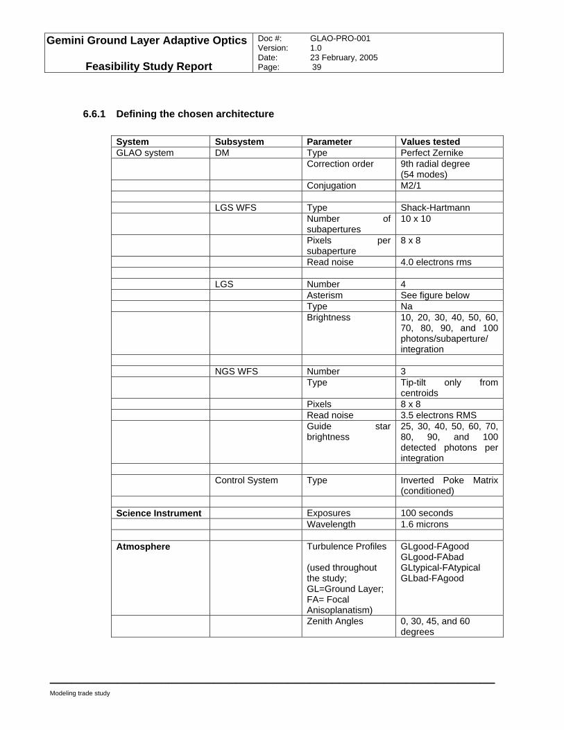
Gemini Ground Layer Adaptive Optics
Feasibility Study Report
Doc #: GLAO-PRO-001 Version: 1.0 Date: 23 February, 2005 Page: 39
____________________________________________________________
Modeling trade study
6.6.1 Defining the chosen architecture System Subsystem Parameter Values tested GLAO system DM Type Perfect Zernike Correction order 9th radial degree
(54 modes) Conjugation M2/1 LGS WFS Type Shack-Hartmann Number of
subapertures 10 x 10
Pixels per subaperture
8 x 8
Read noise 4.0 electrons rms LGS Number 4 Asterism See figure below Type Na Brightness 10, 20, 30, 40, 50, 60,
70, 80, 90, and 100 photons/subaperture/ integration
NGS WFS Number 3 Type Tip-tilt only from
centroids Pixels 8 x 8 Read noise 3.5 electrons RMS Guide star
brightness 25, 30, 40, 50, 60, 70, 80, 90, and 100 detected photons per integration
Control System Type Inverted Poke Matrix
(conditioned) Science Instrument Exposures 100 seconds Wavelength 1.6 microns Atmosphere Turbulence Profiles
(used throughout the study; GL=Ground Layer; FA= Focal Anisoplanatism)
GLgood-FAgood GLgood-FAbad GLtypical-FAtypical GLbad-FAgood
Zenith Angles 0, 30, 45, and 60 degrees
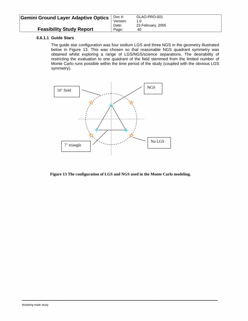
Gemini Ground Layer Adaptive Optics
Feasibility Study Report
Doc #: GLAO-PRO-001 Version: 1.0 Date: 23 February, 2005 Page: 40
____________________________________________________________
Modeling trade study
6.6.1.1 Guide Stars
The guide star configuration was four sodium LGS and three NGS in the geometry illustrated below in Figure 13. This was chosen so that reasonable NGS quadrant symmetry was obtained whilst exploring a range of LGS/NGS/science separations. The desirability of restricting the evaluation to one quadrant of the field stemmed from the limited number of Monte Carlo runs possible within the time period of the study (coupled with the obvious LGS symmetry).
Figure 13 The configuration of LGS and NGS used in the Monte Carlo modeling.
Na LGS
NGS 10’ field
7’ triangle
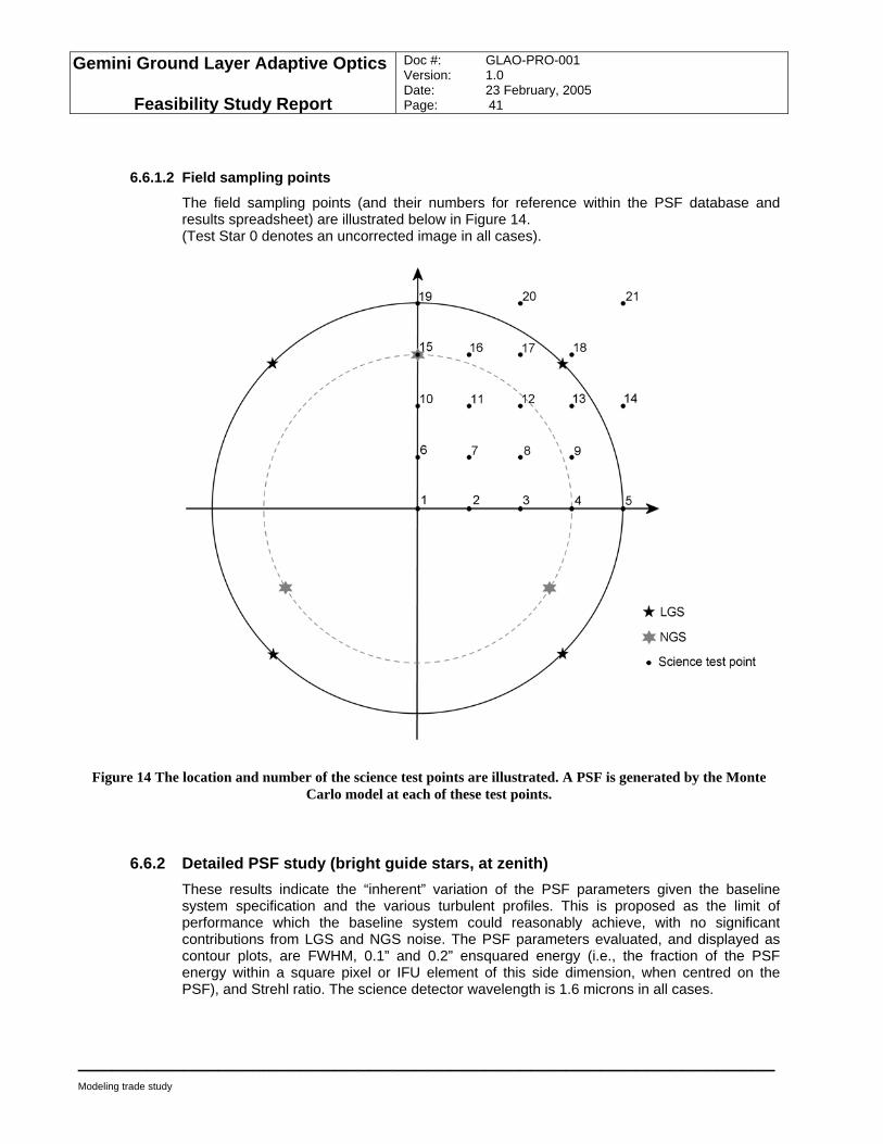
Gemini Ground Layer Adaptive Optics
Feasibility Study Report
Doc #: GLAO-PRO-001 Version: 1.0 Date: 23 February, 2005 Page: 41
____________________________________________________________
Modeling trade study
6.6.1.2 Field sampling points
The field sampling points (and their numbers for reference within the PSF database and results spreadsheet) are illustrated below in Figure 14. (Test Star 0 denotes an uncorrected image in all cases).
Figure 14 The location and number of the science test points are illustrated. A PSF is generated by the Monte Carlo model at each of these test points.
6.6.2 Detailed PSF study (bright guide stars, at zenith) These results indicate the “inherent” variation of the PSF parameters given the baseline system specification and the various turbulent profiles. This is proposed as the limit of performance which the baseline system could reasonably achieve, with no significant contributions from LGS and NGS noise. The PSF parameters evaluated, and displayed as contour plots, are FWHM, 0.1” and 0.2” ensquared energy (i.e., the fraction of the PSF energy within a square pixel or IFU element of this side dimension, when centred on the PSF), and Strehl ratio. The science detector wavelength is 1.6 microns in all cases.
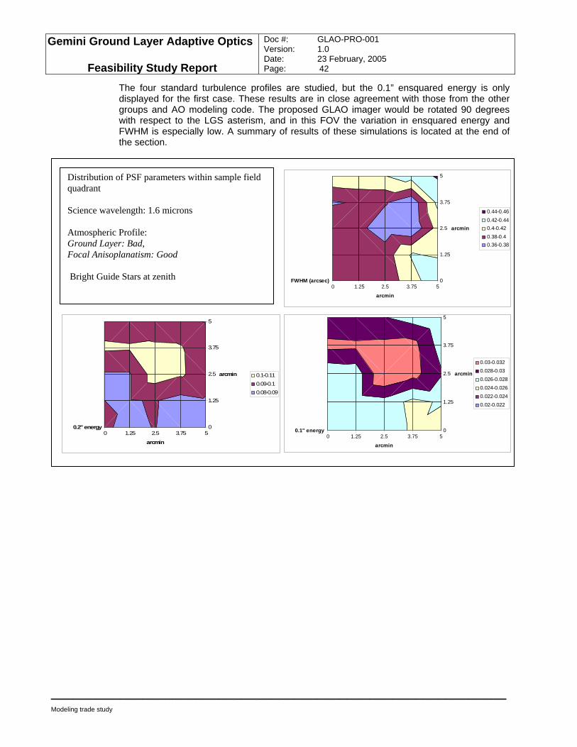
Gemini Ground Layer Adaptive Optics
Feasibility Study Report
Doc #: GLAO-PRO-001 Version: 1.0 Date: 23 February, 2005 Page: 42
____________________________________________________________
Modeling trade study
The four standard turbulence profiles are studied, but the 0.1” ensquared energy is only displayed for the first case. These results are in close agreement with those from the other groups and AO modeling code. The proposed GLAO imager would be rotated 90 degrees with respect to the LGS asterism, and in this FOV the variation in ensquared energy and FWHM is especially low. A summary of results of these simulations is located at the end of the section.
0 1.25 2.5 3.75 50
1.25
2.5
3.75
5
FWHM (arcsec)
arcmin
arcmin
0.44-0.460.42-0.440.4-0.420.38-0.40.36-0.38
0 1.25 2.5 3.75 50
1.25
2.5
3.75
5
0.1" energy
arcmin
arcmin
0.03-0.0320.028-0.030.026-0.0280.024-0.0260.022-0.0240.02-0.022
Distribution of PSF parameters within sample field quadrant Science wavelength: 1.6 microns Atmospheric Profile: Ground Layer: Bad, Focal Anisoplanatism: Good Bright Guide Stars at zenith
0 1.25 2.5 3.75 50
1.25
2.5
3.75
5
0.2" energy
arcmin
arcmin 0.1-0.110.09-0.10.08-0.09
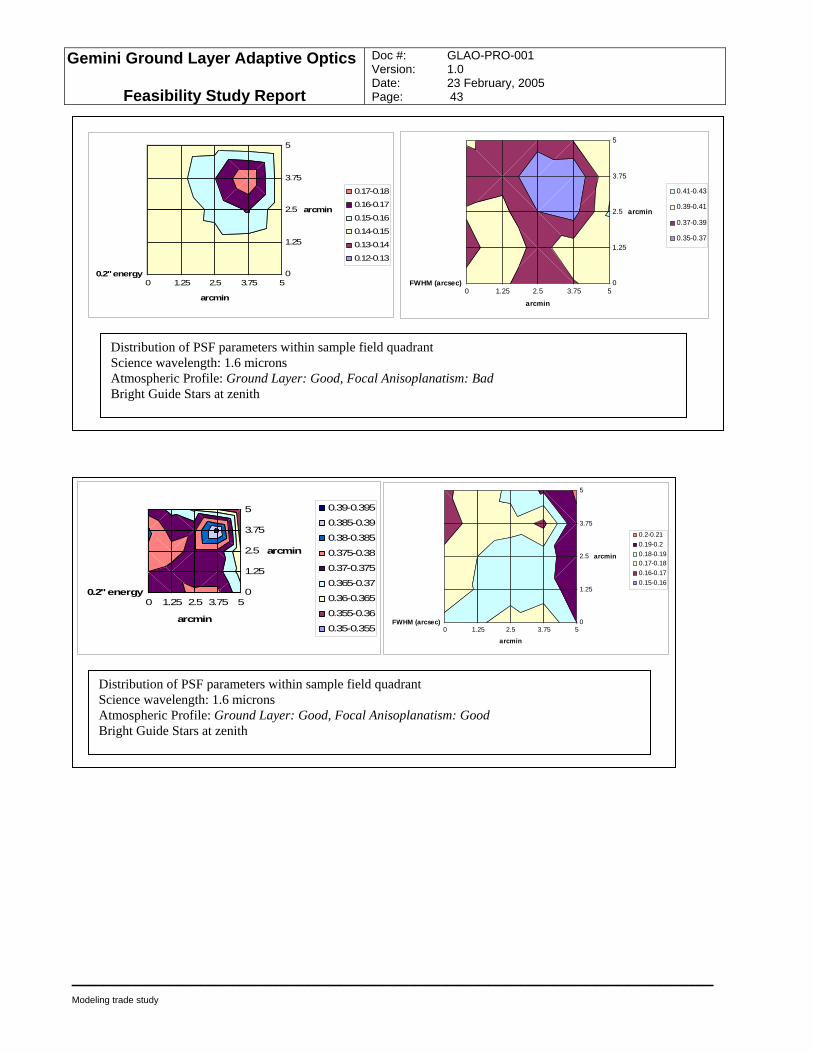
Gemini Ground Layer Adaptive Optics
Feasibility Study Report
Doc #: GLAO-PRO-001 Version: 1.0 Date: 23 February, 2005 Page: 43
____________________________________________________________
Modeling trade study
0 1.25 2.5 3.75 50
1.25
2.5
3.75
5
FWHM (arcsec)
arcmin
arcmin
0.2-0.210.19-0.20.18-0.190.17-0.180.16-0.170.15-0.16
Distribution of PSF parameters within sample field quadrant Science wavelength: 1.6 microns Atmospheric Profile: Ground Layer: Good, Focal Anisoplanatism: Good Bright Guide Stars at zenith
0 1.25 2.5 3.75 50
1.25
2.5
3.75
5
0.2" energy
arcmin
arcmin
0.39-0.395
0.385-0.39
0.38-0.385
0.375-0.38
0.37-0.375
0.365-0.37
0.36-0.365
0.355-0.36
0.35-0.355
0 1.25 2.5 3.75 50
1.25
2.5
3.75
5
FWHM (arcsec)
arcmin
arcmin
0.41-0.43
0.39-0.41
0.37-0.39
0.35-0.37
Distribution of PSF parameters within sample field quadrant Science wavelength: 1.6 microns Atmospheric Profile: Ground Layer: Good, Focal Anisoplanatism: Bad Bright Guide Stars at zenith
0 1.25 2.5 3.75 50
1.25
2.5
3.75
5
0.2" energy
arcmin
arcmin
0.17-0.18
0.16-0.17
0.15-0.16
0.14-0.15
0.13-0.14
0.12-0.13
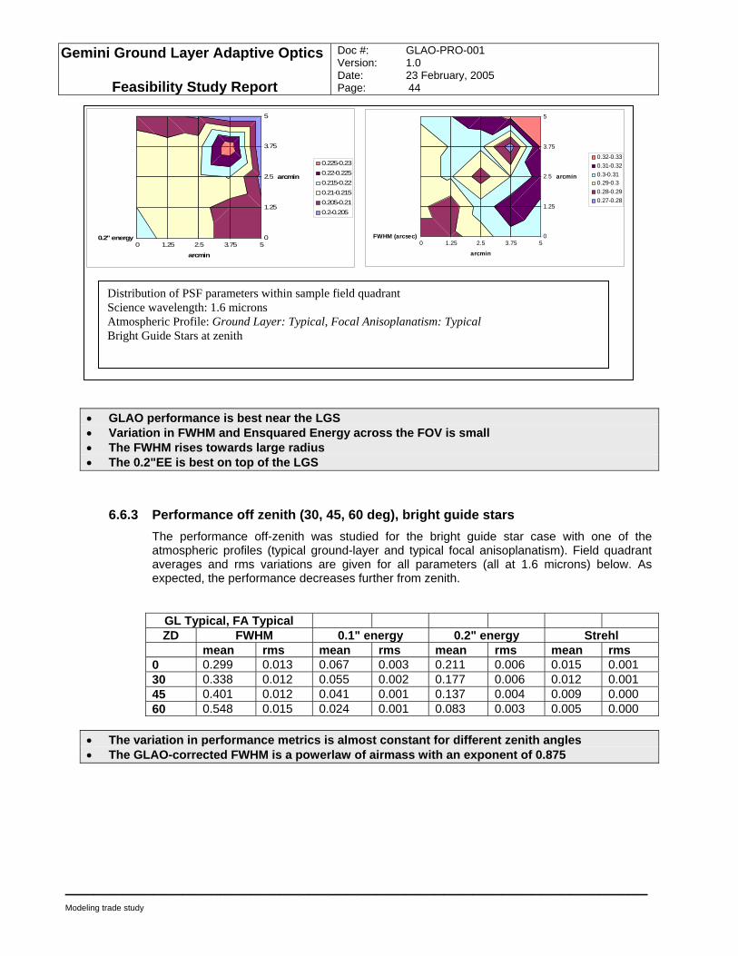
Gemini Ground Layer Adaptive Optics
Feasibility Study Report
Doc #: GLAO-PRO-001 Version: 1.0 Date: 23 February, 2005 Page: 44
____________________________________________________________
Modeling trade study
• GLAO performance is best near the LGS • Variation in FWHM and Ensquared Energy across the FOV is small • The FWHM rises towards large radius • The 0.2"EE is best on top of the LGS
6.6.3 Performance off zenith (30, 45, 60 deg), bright guide stars The performance off-zenith was studied for the bright guide star case with one of the atmospheric profiles (typical ground-layer and typical focal anisoplanatism). Field quadrant averages and rms variations are given for all parameters (all at 1.6 microns) below. As expected, the performance decreases further from zenith.
GL Typical, FA Typical ZD FWHM 0.1" energy 0.2" energy Strehl
mean rms mean rms mean rms mean rms 0 0.299 0.013 0.067 0.003 0.211 0.006 0.015 0.001 30 0.338 0.012 0.055 0.002 0.177 0.006 0.012 0.001 45 0.401 0.012 0.041 0.001 0.137 0.004 0.009 0.000 60 0.548 0.015 0.024 0.001 0.083 0.003 0.005 0.000
• The variation in performance metrics is almost constant for different zenith angles • The GLAO-corrected FWHM is a powerlaw of airmass with an exponent of 0.875
0 1.25 2.5 3.75 50
1.25
2.5
3.75
5
FWHM (arcsec)
arcmin
arcmin
0.32-0.330.31-0.320.3-0.310.29-0.30.28-0.290.27-0.28
Distribution of PSF parameters within sample field quadrant Science wavelength: 1.6 microns Atmospheric Profile: Ground Layer: Typical, Focal Anisoplanatism: Typical Bright Guide Stars at zenith
0 1.25 2.5 3.75 50
1.25
2.5
3.75
5
0.2" energy
arcmin
arcmin
0.225-0.230.22-0.2250.215-0.220.21-0.2150.205-0.210.2-0.205
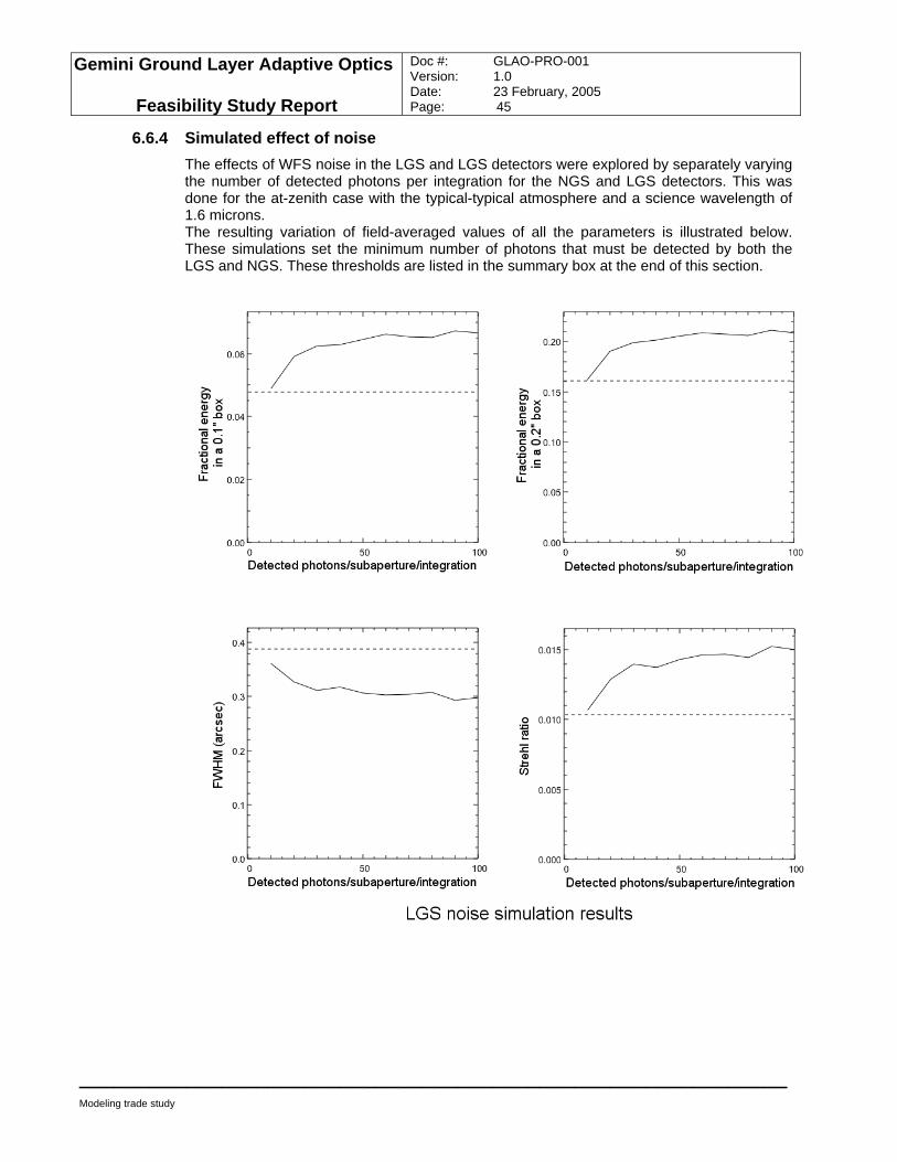
Gemini Ground Layer Adaptive Optics
Feasibility Study Report
Doc #: GLAO-PRO-001 Version: 1.0 Date: 23 February, 2005 Page: 45
____________________________________________________________
Modeling trade study
6.6.4 Simulated effect of noise The effects of WFS noise in the LGS and LGS detectors were explored by separately varying the number of detected photons per integration for the NGS and LGS detectors. This was done for the at-zenith case with the typical-typical atmosphere and a science wavelength of 1.6 microns. The resulting variation of field-averaged values of all the parameters is illustrated below. These simulations set the minimum number of photons that must be detected by both the LGS and NGS. These thresholds are listed in the summary box at the end of this section.
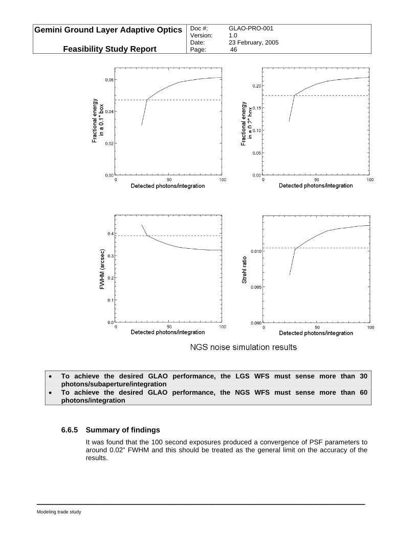
Gemini Ground Layer Adaptive Optics
Feasibility Study Report
Doc #: GLAO-PRO-001 Version: 1.0 Date: 23 February, 2005 Page: 46
____________________________________________________________
Modeling trade study
• To achieve the desired GLAO performance, the LGS WFS must sense more than 30 photons/subaperture/integration
• To achieve the desired GLAO performance, the NGS WFS must sense more than 60 photons/integration
6.6.5 Summary of findings It was found that the 100 second exposures produced a convergence of PSF parameters to around 0.02” FWHM and this should be treated as the general limit on the accuracy of the results.
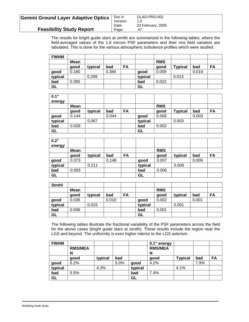
Gemini Ground Layer Adaptive Optics
Feasibility Study Report
Doc #: GLAO-PRO-001 Version: 1.0 Date: 23 February, 2005 Page: 47
____________________________________________________________
Modeling trade study
The results for bright guide stars at zenith are summarized in the following tables, where the field-averaged values of the 1.6 micron PSF parameters and their rms field variation are tabulated. This is done for the various atmospheric turbulence profiles which were studied. FWHM Mean RMS good typical bad FA good Typical bad FA good 0.180 0.384 good 0.009 0.019 typical 0.299 typical 0.013 bad 0.395 bad 0.022 GL GL 0.1" energy
Mean RMS good typical bad FA good Typical bad FA good 0.144 0.044 good 0.006 0.003 typical 0.067 typical 0.003 bad 0.028 bad 0.002 GL GL 0.2" energy
Mean RMS good typical bad FA good typical bad FA good 0.373 0.148 good 0.007 0.009 typical 0.211 typical 0.006 bad 0.093 bad 0.006 GL GL Strehl Mean RMS good typical bad FA good typical bad FA good 0.036 0.010 good 0.002 0.001 typical 0.015 typical 0.001 bad 0.006 bad 0.001 GL GL The following tables illustrate the fractional variability of the PSF parameters across the field for the above cases (bright guide stars at zenith). These results include the region near the LGS and beyond. The uniformity is even higher interior to the LGS asterism. FWHM 0.1" energy RMS/MEA
N RMS/MEA
N
good typical bad good Typical bad FA good 5.2% 5.0% good 4.2% 7.9% typical 4.3% typical 4.1% bad 5.5% bad 7.4% GL GL
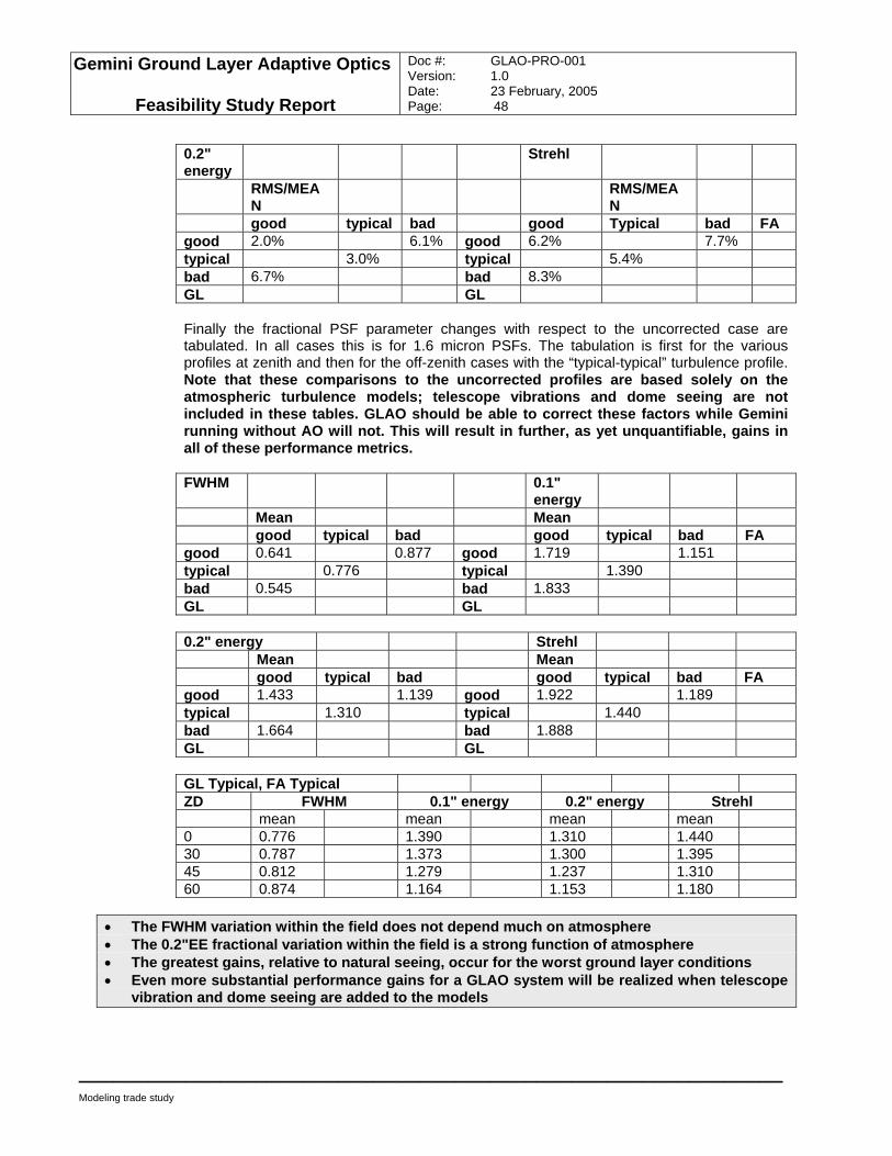
Gemini Ground Layer Adaptive Optics
Feasibility Study Report
Doc #: GLAO-PRO-001 Version: 1.0 Date: 23 February, 2005 Page: 48
____________________________________________________________
Modeling trade study
0.2" energy
Strehl
RMS/MEAN
RMS/MEAN
good typical bad good Typical bad FA good 2.0% 6.1% good 6.2% 7.7% typical 3.0% typical 5.4% bad 6.7% bad 8.3% GL GL Finally the fractional PSF parameter changes with respect to the uncorrected case are tabulated. In all cases this is for 1.6 micron PSFs. The tabulation is first for the various profiles at zenith and then for the off-zenith cases with the “typical-typical” turbulence profile. Note that these comparisons to the uncorrected profiles are based solely on the atmospheric turbulence models; telescope vibrations and dome seeing are not included in these tables. GLAO should be able to correct these factors while Gemini running without AO will not. This will result in further, as yet unquantifiable, gains in all of these performance metrics. FWHM 0.1"
energy
Mean Mean good typical bad good typical bad FA good 0.641 0.877 good 1.719 1.151 typical 0.776 typical 1.390 bad 0.545 bad 1.833 GL GL 0.2" energy Strehl Mean Mean good typical bad good typical bad FA good 1.433 1.139 good 1.922 1.189 typical 1.310 typical 1.440 bad 1.664 bad 1.888 GL GL GL Typical, FA Typical ZD FWHM 0.1" energy 0.2" energy Strehl mean mean mean mean 0 0.776 1.390 1.310 1.440 30 0.787 1.373 1.300 1.395 45 0.812 1.279 1.237 1.310 60 0.874 1.164 1.153 1.180
• The FWHM variation within the field does not depend much on atmosphere • The 0.2"EE fractional variation within the field is a strong function of atmosphere • The greatest gains, relative to natural seeing, occur for the worst ground layer conditions • Even more substantial performance gains for a GLAO system will be realized when telescope
vibration and dome seeing are added to the models
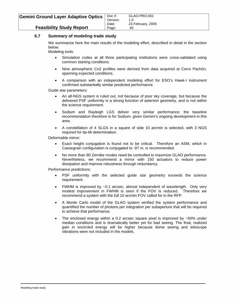
Gemini Ground Layer Adaptive Optics
Feasibility Study Report
Doc #: GLAO-PRO-001 Version: 1.0 Date: 23 February, 2005 Page: 49
____________________________________________________________
Modeling trade study
6.7 Summary of modeling trade study We summarize here the main results of the modeling effort, described in detail in the section below. Modeling tools:
• Simulation codes at all three participating institutions were cross-validated using common starting conditions.
• Nine atmospheric Cn2 profiles were derived from data acquired at Cerro Pachón, spanning expected conditions.
• A comparison with an independent modeling effort for ESO’s Hawk-I instrument confirmed substantially similar predicted performance.
Guide star parameters: • An all-NGS system is ruled out, not because of poor sky coverage, but because the
delivered PSF uniformity is a strong function of asterism geometry, and is not within the science requirement.
• Sodium and Rayleigh LGS deliver very similar performance; the baseline recommendation therefore is for Sodium, given Gemini’s ongoing development in this area.
• A constellation of 4 SLGS in a square of side 10 arcmin is selected, with 3 NGS required for tip-tilt determination.
Deformable mirror: • Exact height conjugation is found not to be critical. Therefore an ASM, which in
Cassegrain configuration is conjugated to -97 m, is recommended.
• No more than 80 Zernike modes need be controlled to maximize GLAO performance. Nevertheless, we recommend a mirror with 150 actuators to reduce power dissipation and improve robustness through redundancy.
Performance predictions: • PSF uniformity with the selected guide star geometry exceeds the science
requirement.
• FWHM is improved by ~0.1 arcsec, almost independent of wavelength. Only very modest improvement in FWHM is seen if the FOV is reduced. Therefore we recommend a system with the full 10 arcmin FOV called for in the RFP.
• A Monte Carlo model of the GLAO system verified the system performance and quantified the number of photons per integration per subaperture that will be required to achieve that performance.
• The enclosed energy within a 0.2 arcsec square pixel is improved by ~50% under median conditions and is dramatically better yet for bad seeing. The final, realized gain in encircled energy will be higher because dome seeing and telescope vibrations were not included in the models.
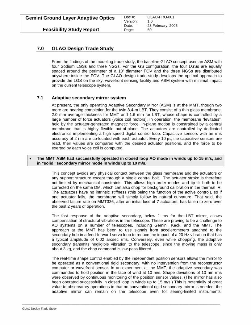
Gemini Ground Layer Adaptive Optics
Feasibility Study Report
Doc #: GLAO-PRO-001 Version: 1.0 Date: 23 February, 2005 Page: 50
____________________________________________________________
GLAO Design Trade Study
7.0 GLAO Design Trade Study
From the findings of the modeling trade study, the baseline GLAO concept uses an ASM with four Sodium LGSs and three NGSs. For the GS configuration, the four LGSs are equally spaced around the perimeter of a 10’ diameter FOV and the three NGSs are distributed anywhere inside the FOV. The GLAO design trade study develops the optimal approach to provide the LGS on the sky, wavefront sensing facility and ASM system with minimal impact on the current telescope system.
7.1 Adaptive secondary mirror system At present, the only operating Adaptive Secondary Mirror (ASM) is at the MMT, though two more are nearing completion for the twin 8.4-m LBT. They consist of a thin glass membrane, 2.0 mm average thickness for MMT and 1.6 mm for LBT, whose shape is controlled by a large number of force actuators (voice coil motors). In operation, the membrane “levitates”, held by the actuator-generated magnetic force. In-plane motion is constrained by a central membrane that is highly flexible out-of-plane. The actuators are controlled by dedicated electronics implementing a high speed digital control loop. Capacitive sensors with an rms accuracy of 2 nm are co-located with each actuator. Every 10 µs, the capacitive sensors are read, their values are compared with the desired actuator positions, and the force to be exerted by each voice coil is computed.
• The MMT ASM had successfully operated in closed loop AO mode in winds up to 15 m/s, and in “solid” secondary mirror mode in winds up to 10 m/s.
This concept avoids any physical contact between the glass membrane and the actuators or any support structure except through a single central bolt. The actuator stroke is therefore not limited by mechanical constraints. This allows high order modes and tip-tilt both to be corrected on the same DM, which can also chop for background calibration in the thermal IR. The actuators have no intrinsic stiffness (this being the function of the active control), so if one actuator fails, the membrane will simply follow its natural curvature. That said, the observed failure rate on MMT336, after an initial loss of 7 actuators, has fallen to zero over the past 2 years of operation. The fast response of the adaptive secondary, below 1 ms for the LBT mirror, allows compensation of structural vibrations in the telescope. These are proving to be a challenge to AO systems on a number of telescopes, including Gemini, Keck, and the MMT. The approach at the MMT has been to use signals from accelerometers attached to the secondary hub in a feed-forward servo loop to reduce the impact of a 20 Hz vibration that has a typical amplitude of 0.02 arcsec rms. Conversely, even while chopping, the adaptive secondary transmits negligible vibration to the telescope, since the moving mass is only about 3 kg, and the chop command is low-pass filtered. The real-time shape control enabled by the independent position sensors allows the mirror to be operated as a conventional rigid secondary, with no intervention from the reconstructor computer or wavefront sensor. In an experiment at the MMT, the adaptive secondary was commanded to hold position in the face of wind at 10 m/s. Shape deviations of 10 nm rms were observed by continuous monitoring of the position sensor values. (The mirror has also been operated successfully in closed loop in winds up to 15 m/s.) This is potentially of great value to observatory operations in that no conventional rigid secondary mirror is needed: the adaptive mirror can remain on the telescope even for seeing-limited instruments.
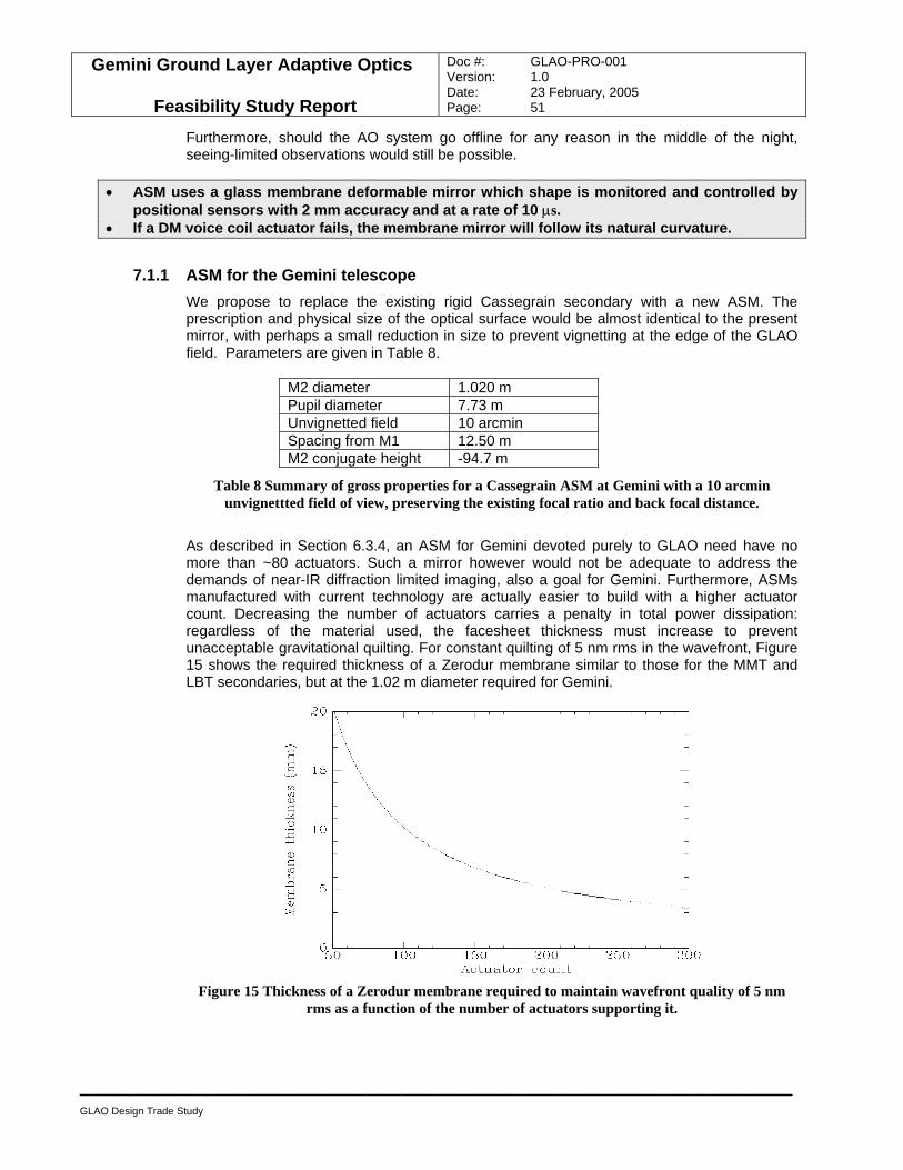
Gemini Ground Layer Adaptive Optics
Feasibility Study Report
Doc #: GLAO-PRO-001 Version: 1.0 Date: 23 February, 2005 Page: 51
____________________________________________________________
GLAO Design Trade Study
Furthermore, should the AO system go offline for any reason in the middle of the night, seeing-limited observations would still be possible.
• ASM uses a glass membrane deformable mirror which shape is monitored and controlled by positional sensors with 2 mm accuracy and at a rate of 10 µs.
• If a DM voice coil actuator fails, the membrane mirror will follow its natural curvature.
7.1.1 ASM for the Gemini telescope We propose to replace the existing rigid Cassegrain secondary with a new ASM. The prescription and physical size of the optical surface would be almost identical to the present mirror, with perhaps a small reduction in size to prevent vignetting at the edge of the GLAO field. Parameters are given in Table 8.
M2 diameter 1.020 m Pupil diameter 7.73 m Unvignetted field 10 arcmin Spacing from M1 12.50 m M2 conjugate height -94.7 m
Table 8 Summary of gross properties for a Cassegrain ASM at Gemini with a 10 arcmin unvignettted field of view, preserving the existing focal ratio and back focal distance.
As described in Section 6.3.4, an ASM for Gemini devoted purely to GLAO need have no more than ~80 actuators. Such a mirror however would not be adequate to address the demands of near-IR diffraction limited imaging, also a goal for Gemini. Furthermore, ASMs manufactured with current technology are actually easier to build with a higher actuator count. Decreasing the number of actuators carries a penalty in total power dissipation: regardless of the material used, the facesheet thickness must increase to prevent unacceptable gravitational quilting. For constant quilting of 5 nm rms in the wavefront, Figure 15 shows the required thickness of a Zerodur membrane similar to those for the MMT and LBT secondaries, but at the 1.02 m diameter required for Gemini.
Figure 15 Thickness of a Zerodur membrane required to maintain wavefront quality of 5 nm
rms as a function of the number of actuators supporting it.
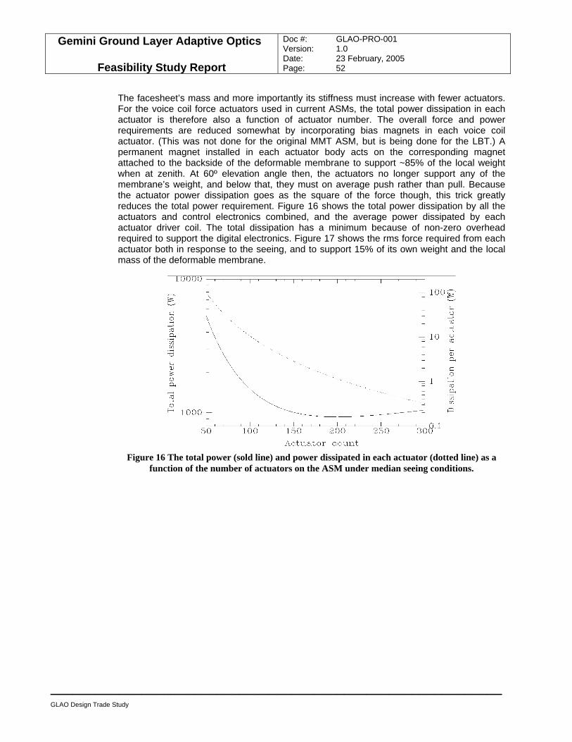
Gemini Ground Layer Adaptive Optics
Feasibility Study Report
Doc #: GLAO-PRO-001 Version: 1.0 Date: 23 February, 2005 Page: 52
____________________________________________________________
GLAO Design Trade Study
The facesheet’s mass and more importantly its stiffness must increase with fewer actuators. For the voice coil force actuators used in current ASMs, the total power dissipation in each actuator is therefore also a function of actuator number. The overall force and power requirements are reduced somewhat by incorporating bias magnets in each voice coil actuator. (This was not done for the original MMT ASM, but is being done for the LBT.) A permanent magnet installed in each actuator body acts on the corresponding magnet attached to the backside of the deformable membrane to support ~85% of the local weight when at zenith. At 60º elevation angle then, the actuators no longer support any of the membrane’s weight, and below that, they must on average push rather than pull. Because the actuator power dissipation goes as the square of the force though, this trick greatly reduces the total power requirement. Figure 16 shows the total power dissipation by all the actuators and control electronics combined, and the average power dissipated by each actuator driver coil. The total dissipation has a minimum because of non-zero overhead required to support the digital electronics. Figure 17 shows the rms force required from each actuator both in response to the seeing, and to support 15% of its own weight and the local mass of the deformable membrane.
Figure 16 The total power (sold line) and power dissipated in each actuator (dotted line) as a
function of the number of actuators on the ASM under median seeing conditions.
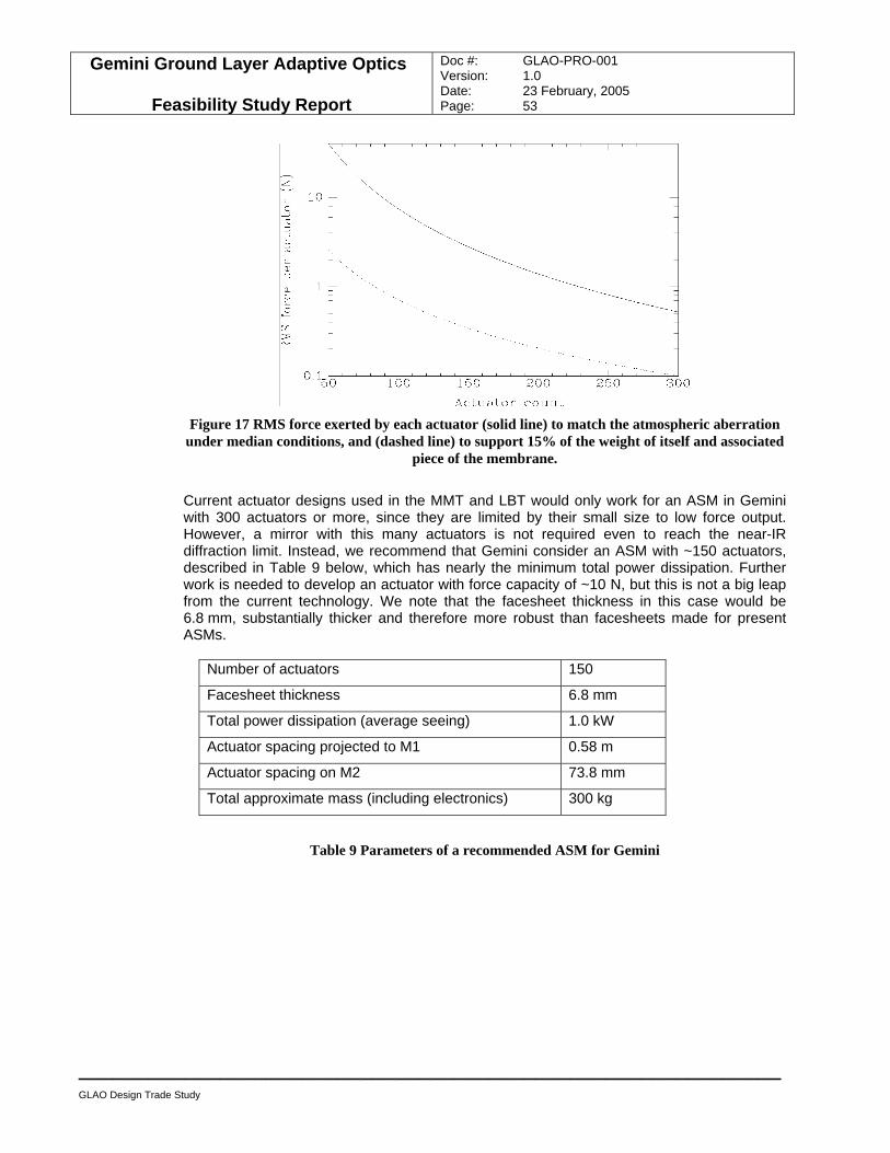
Gemini Ground Layer Adaptive Optics
Feasibility Study Report
Doc #: GLAO-PRO-001 Version: 1.0 Date: 23 February, 2005 Page: 53
____________________________________________________________
GLAO Design Trade Study
Figure 17 RMS force exerted by each actuator (solid line) to match the atmospheric aberration
under median conditions, and (dashed line) to support 15% of the weight of itself and associated piece of the membrane.
Current actuator designs used in the MMT and LBT would only work for an ASM in Gemini with 300 actuators or more, since they are limited by their small size to low force output. However, a mirror with this many actuators is not required even to reach the near-IR diffraction limit. Instead, we recommend that Gemini consider an ASM with ~150 actuators, described in Table 9 below, which has nearly the minimum total power dissipation. Further work is needed to develop an actuator with force capacity of ~10 N, but this is not a big leap from the current technology. We note that the facesheet thickness in this case would be 6.8 mm, substantially thicker and therefore more robust than facesheets made for present ASMs.
Number of actuators 150
Facesheet thickness 6.8 mm
Total power dissipation (average seeing) 1.0 kW
Actuator spacing projected to M1 0.58 m
Actuator spacing on M2 73.8 mm
Total approximate mass (including electronics) 300 kg
Table 9 Parameters of a recommended ASM for Gemini
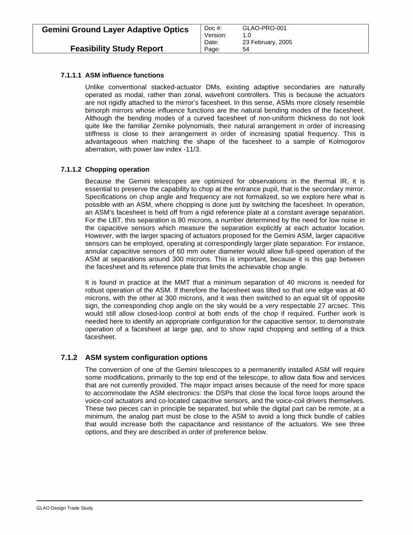
Gemini Ground Layer Adaptive Optics
Feasibility Study Report
Doc #: GLAO-PRO-001 Version: 1.0 Date: 23 February, 2005 Page: 54
____________________________________________________________
GLAO Design Trade Study
7.1.1.1 ASM influence functions
Unlike conventional stacked-actuator DMs, existing adaptive secondaries are naturally operated as modal, rather than zonal, wavefront controllers. This is because the actuators are not rigidly attached to the mirror’s facesheet. In this sense, ASMs more closely resemble bimorph mirrors whose influence functions are the natural bending modes of the facesheet. Although the bending modes of a curved facesheet of non-uniform thickness do not look quite like the familiar Zernike polynomials, their natural arrangement in order of increasing stiffness is close to their arrangement in order of increasing spatial frequency. This is advantageous when matching the shape of the facesheet to a sample of Kolmogorov aberration, with power law index -11/3.
7.1.1.2 Chopping operation
Because the Gemini telescopes are optimized for observations in the thermal IR, it is essential to preserve the capability to chop at the entrance pupil, that is the secondary mirror. Specifications on chop angle and frequency are not formalized, so we explore here what is possible with an ASM, where chopping is done just by switching the facesheet. In operation, an ASM’s facesheet is held off from a rigid reference plate at a constant average separation. For the LBT, this separation is 80 microns, a number determined by the need for low noise in the capacitive sensors which measure the separation explicitly at each actuator location. However, with the larger spacing of actuators proposed for the Gemini ASM, larger capacitive sensors can be employed, operating at correspondingly larger plate separation. For instance, annular capacitive sensors of 60 mm outer diameter would allow full-speed operation of the ASM at separations around 300 microns. This is important, because it is this gap between the facesheet and its reference plate that limits the achievable chop angle. It is found in practice at the MMT that a minimum separation of 40 microns is needed for robust operation of the ASM. If therefore the facesheet was tilted so that one edge was at 40 microns, with the other at 300 microns, and it was then switched to an equal tilt of opposite sign, the corresponding chop angle on the sky would be a very respectable 27 arcsec. This would still allow closed-loop control at both ends of the chop if required. Further work is needed here to identify an appropriate configuration for the capacitive sensor, to demonstrate operation of a facesheet at large gap, and to show rapid chopping and settling of a thick facesheet.
7.1.2 ASM system configuration options The conversion of one of the Gemini telescopes to a permanently installed ASM will require some modifications, primarily to the top end of the telescope, to allow data flow and services that are not currently provided. The major impact arises because of the need for more space to accommodate the ASM electronics: the DSPs that close the local force loops around the voice-coil actuators and co-located capacitive sensors, and the voice-coil drivers themselves. These two pieces can in principle be separated, but while the digital part can be remote, at a minimum, the analog part must be close to the ASM to avoid a long thick bundle of cables that would increase both the capacitance and resistance of the actuators. We see three options, and they are described in order of preference below.
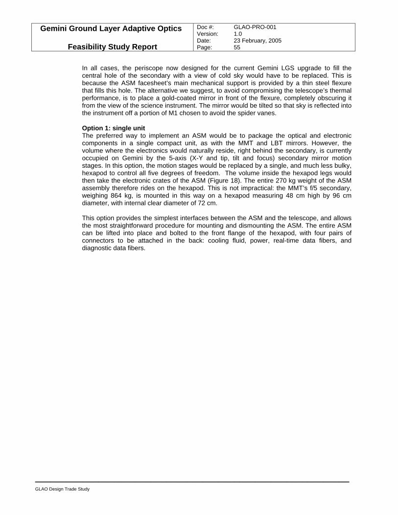
Gemini Ground Layer Adaptive Optics
Feasibility Study Report
Doc #: GLAO-PRO-001 Version: 1.0 Date: 23 February, 2005 Page: 55
____________________________________________________________
GLAO Design Trade Study
In all cases, the periscope now designed for the current Gemini LGS upgrade to fill the central hole of the secondary with a view of cold sky would have to be replaced. This is because the ASM facesheet’s main mechanical support is provided by a thin steel flexure that fills this hole. The alternative we suggest, to avoid compromising the telescope’s thermal performance, is to place a gold-coated mirror in front of the flexure, completely obscuring it from the view of the science instrument. The mirror would be tilted so that sky is reflected into the instrument off a portion of M1 chosen to avoid the spider vanes. Option 1: single unit The preferred way to implement an ASM would be to package the optical and electronic components in a single compact unit, as with the MMT and LBT mirrors. However, the volume where the electronics would naturally reside, right behind the secondary, is currently occupied on Gemini by the 5-axis (X-Y and tip, tilt and focus) secondary mirror motion stages. In this option, the motion stages would be replaced by a single, and much less bulky, hexapod to control all five degrees of freedom. The volume inside the hexapod legs would then take the electronic crates of the ASM (Figure 18). The entire 270 kg weight of the ASM assembly therefore rides on the hexapod. This is not impractical: the MMT’s f/5 secondary, weighing 864 kg, is mounted in this way on a hexapod measuring 48 cm high by 96 cm diameter, with internal clear diameter of 72 cm. This option provides the simplest interfaces between the ASM and the telescope, and allows the most straightforward procedure for mounting and dismounting the ASM. The entire ASM can be lifted into place and bolted to the front flange of the hexapod, with four pairs of connectors to be attached in the back: cooling fluid, power, real-time data fibers, and diagnostic data fibers.
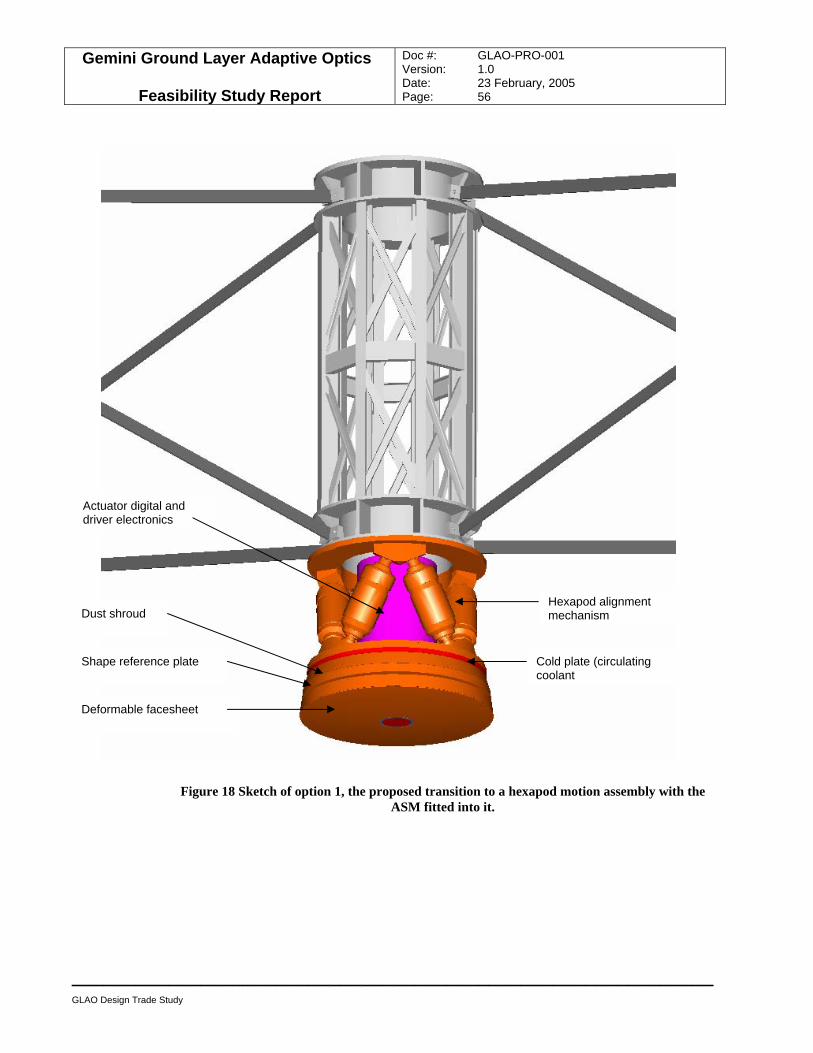
Gemini Ground Layer Adaptive Optics
Feasibility Study Report
Doc #: GLAO-PRO-001 Version: 1.0 Date: 23 February, 2005 Page: 56
____________________________________________________________
GLAO Design Trade Study
Figure 18 Sketch of option 1, the proposed transition to a hexapod motion assembly with the ASM fitted into it.
Dust shroud
Actuator digital and driver electronics
Deformable facesheet
Cold plate (circulating coolant
Hexapod alignment mechanism
Shape reference plate
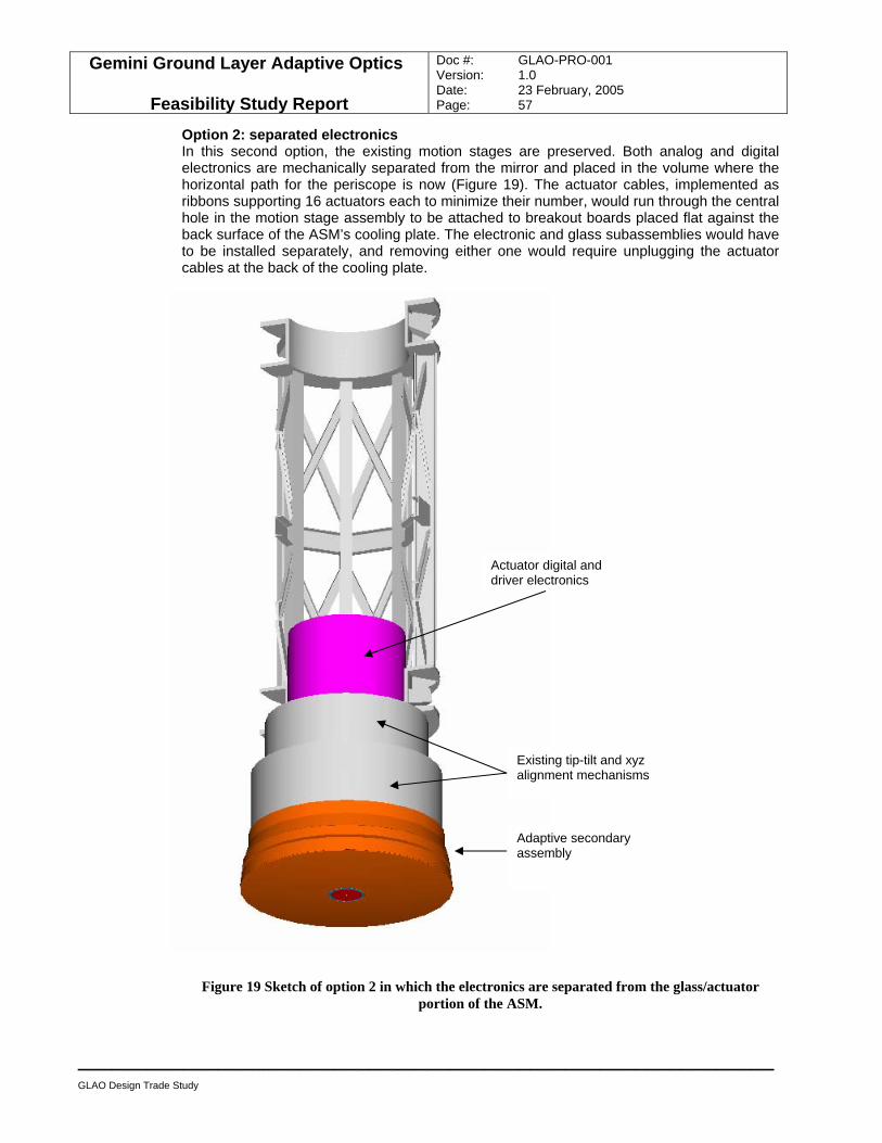
Gemini Ground Layer Adaptive Optics
Feasibility Study Report
Doc #: GLAO-PRO-001 Version: 1.0 Date: 23 February, 2005 Page: 57
____________________________________________________________
GLAO Design Trade Study
Option 2: separated electronics In this second option, the existing motion stages are preserved. Both analog and digital electronics are mechanically separated from the mirror and placed in the volume where the horizontal path for the periscope is now (Figure 19). The actuator cables, implemented as ribbons supporting 16 actuators each to minimize their number, would run through the central hole in the motion stage assembly to be attached to breakout boards placed flat against the back surface of the ASM’s cooling plate. The electronic and glass subassemblies would have to be installed separately, and removing either one would require unplugging the actuator cables at the back of the cooling plate.
Figure 19 Sketch of option 2 in which the electronics are separated from the glass/actuator portion of the ASM.
Actuator digital and driver electronics
Existing tip-tilt and xyz alignment mechanisms
Adaptive secondary assembly
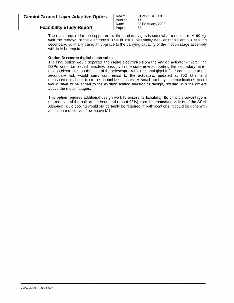
Gemini Ground Layer Adaptive Optics
Feasibility Study Report
Doc #: GLAO-PRO-001 Version: 1.0 Date: 23 February, 2005 Page: 58
____________________________________________________________
GLAO Design Trade Study
The mass required to be supported by the motion stages is somewhat reduced, to ~190 kg, with the removal of the electronics. This is still substantially heavier than Gemini’s existing secondary, so in any case, an upgrade to the carrying capacity of the motion stage assembly will likely be required. Option 3: remote digital electronics The final option would separate the digital electronics from the analog actuator drivers. The DSPs would be placed remotely, possibly in the crate now supporting the secondary mirror motion electronics on the side of the telescope. A bidirectional gigabit fiber connection to the secondary hub would carry commands to the actuators, updated at 100 kHz, and measurements back from the capacitive sensors. A small auxiliary communications board would have to be added to the existing analog electronics design, housed with the drivers above the motion stages. This option requires additional design work to ensure its feasibility. Its principle advantage is the removal of the bulk of the heat load (about 95%) from the immediate vicinity of the ASM. Although liquid cooling would still certainly be required in both locations, it could be done with a minimum of coolant flow above M1.
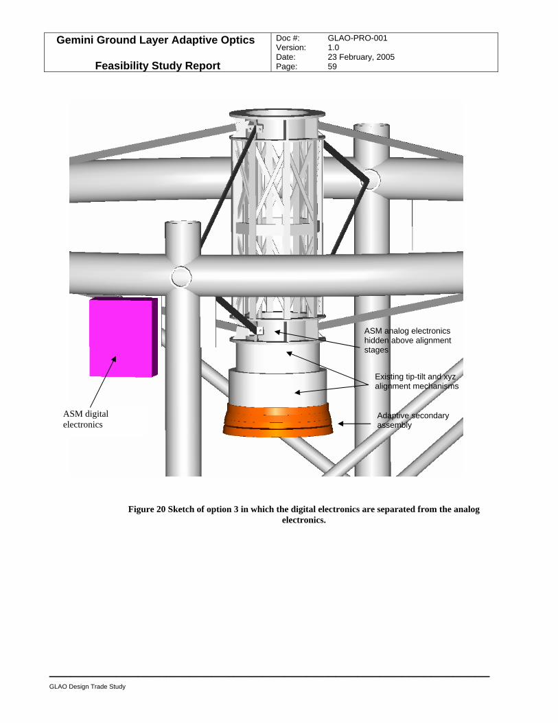
Gemini Ground Layer Adaptive Optics
Feasibility Study Report
Doc #: GLAO-PRO-001 Version: 1.0 Date: 23 February, 2005 Page: 59
____________________________________________________________
GLAO Design Trade Study
Figure 20 Sketch of option 3 in which the digital electronics are separated from the analog electronics.
ASM digital electronics
ASM analog electronics hidden above alignment stages
Existing tip-tilt and xyz alignment mechanisms
Adaptive secondary assembly
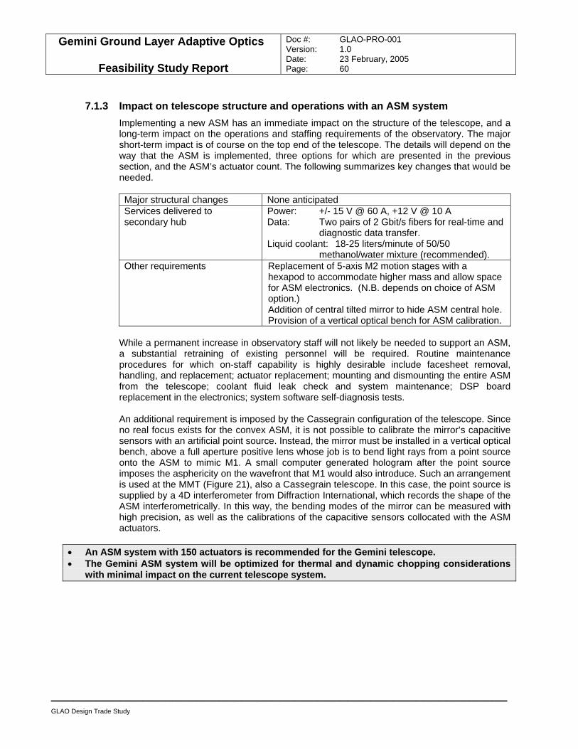
Gemini Ground Layer Adaptive Optics
Feasibility Study Report
Doc #: GLAO-PRO-001 Version: 1.0 Date: 23 February, 2005 Page: 60
____________________________________________________________
GLAO Design Trade Study
7.1.3 Impact on telescope structure and operations with an ASM system Implementing a new ASM has an immediate impact on the structure of the telescope, and a long-term impact on the operations and staffing requirements of the observatory. The major short-term impact is of course on the top end of the telescope. The details will depend on the way that the ASM is implemented, three options for which are presented in the previous section, and the ASM’s actuator count. The following summarizes key changes that would be needed. Major structural changes None anticipated Services delivered to secondary hub
Power: +/- 15 V @ 60 A, +12 V @ 10 A Data: Two pairs of 2 Gbit/s fibers for real-time and
diagnostic data transfer. Liquid coolant: 18-25 liters/minute of 50/50
methanol/water mixture (recommended). Other requirements Replacement of 5-axis M2 motion stages with a
hexapod to accommodate higher mass and allow space for ASM electronics. (N.B. depends on choice of ASM option.) Addition of central tilted mirror to hide ASM central hole. Provision of a vertical optical bench for ASM calibration.
While a permanent increase in observatory staff will not likely be needed to support an ASM, a substantial retraining of existing personnel will be required. Routine maintenance procedures for which on-staff capability is highly desirable include facesheet removal, handling, and replacement; actuator replacement; mounting and dismounting the entire ASM from the telescope; coolant fluid leak check and system maintenance; DSP board replacement in the electronics; system software self-diagnosis tests. An additional requirement is imposed by the Cassegrain configuration of the telescope. Since no real focus exists for the convex ASM, it is not possible to calibrate the mirror’s capacitive sensors with an artificial point source. Instead, the mirror must be installed in a vertical optical bench, above a full aperture positive lens whose job is to bend light rays from a point source onto the ASM to mimic M1. A small computer generated hologram after the point source imposes the asphericity on the wavefront that M1 would also introduce. Such an arrangement is used at the MMT (Figure 21), also a Cassegrain telescope. In this case, the point source is supplied by a 4D interferometer from Diffraction International, which records the shape of the ASM interferometrically. In this way, the bending modes of the mirror can be measured with high precision, as well as the calibrations of the capacitive sensors collocated with the ASM actuators.
• An ASM system with 150 actuators is recommended for the Gemini telescope. • The Gemini ASM system will be optimized for thermal and dynamic chopping considerations
with minimal impact on the current telescope system.
Gemini Ground Layer Adaptive Optics
Feasibility Study Report
Doc #: GLAO-PRO-001 Version: 1.0 Date: 23 February, 2005 Page: 61
____________________________________________________________
GLAO Design Trade Study
Adaptive
secondary Calibration mirror
Interferometer
Secondary transportation cart
Figure 21 The calibration test stand used to record the influence functions and capacitive sensor calibrations of the MMT’s ASM.
7.2 Laser guide star system The Sodium LGS system includes all the facility and equipment required to generate, transmit, sense, steer and project the square LGS pattern, i.e. one LGS at each corner of a 7.07’ square onto the perimeter of a 10’ diameter field. The GLAO LGS system requirements are very similar to the Gemini-S MCAO LGS system except MCAO uses five LGSs with a FOV of 2’ diameter only and its LGS is a cross pattern of five LGSs, i.e. one LGS at each corner of a 1.41’ square plus one LGS at the centre. Since the MCAO LGS system has already passed its Critical Design Review, the GLAO LGS system “borrows” heavily from the MCAO design and the feasibility of adapting the existing design to project a 10’ FOV are described in this section. The GLAO Sodium LGS system (four guide stars) adapts the MCAO LGS system (five guide stars) with the beam transfer optics and laser launch telescope optics modified to project four guide stars over a 10’ field. Detailed description of the MCAO LGS system is available from Gemini, http://ftp.gemini.edu/Groups/AO/BTO_CDR/.
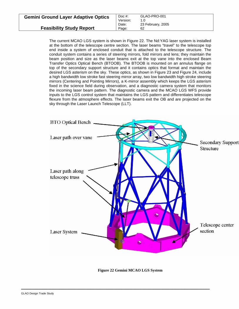
Gemini Ground Layer Adaptive Optics
Feasibility Study Report
Doc #: GLAO-PRO-001 Version: 1.0 Date: 23 February, 2005 Page: 62
____________________________________________________________
GLAO Design Trade Study
The current MCAO LGS system is shown in Figure 22. The Nd:YAG laser system is installed at the bottom of the telescope centre section. The laser beams “travel” to the telescope top end inside a system of enclosed conduit that is attached to the telescope structure. The conduit system contains a series of steering mirrors, fold mirrors and lens; they maintain the beam position and size as the laser beams exit at the top vane into the enclosed Beam Transfer Optics Optical Bench (BTOOB). The BTOOB is mounted on an annulus flange on top of the secondary support structure and it contains optics that format and maintain the desired LGS asterism on the sky. These optics, as shown in Figure 23 and Figure 24, include a high bandwidth low stroke fast steering mirror array, two low bandwidth high stroke steering mirrors (Centering and Pointing Mirrors), a K-mirror assembly which keeps the LGS asterism fixed in the science field during observation, and a diagnostic camera system that monitors the incoming laser beam pattern. The diagnostic camera and the MCAO LGS WFS provide inputs to the LGS control system that maintains the LGS pattern and differentiates telescope flexure from the atmosphere effects. The laser beams exit the OB and are projected on the sky through the Laser Launch Telescope (LLT).
Figure 22 Gemini MCAO LGS System
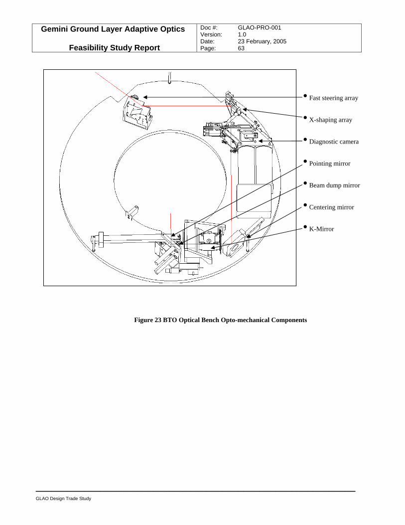
Gemini Ground Layer Adaptive Optics
Feasibility Study Report
Doc #: GLAO-PRO-001 Version: 1.0 Date: 23 February, 2005 Page: 63
____________________________________________________________
GLAO Design Trade Study
Figure 23 BTO Optical Bench Opto-mechanical Components
• Fast steering array
• X-shaping array
• Diagnostic camera
• Pointing mirror
• Beam dump mirror
• Centering mirror
• K-Mirror
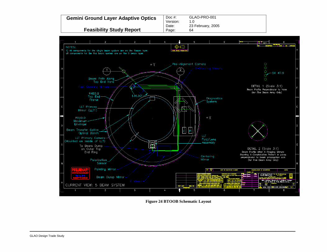
Gemini Ground Layer Adaptive Optics
Feasibility Study Report
Doc #: GLAO-PRO-001 Version: 1.0 Date: 23 February, 2005 Page: 64
________________________________________________________________________________
GLAO Design Trade Study
Figure 24 BTOOB Schematic Layout
Gemini Ground Layer Adaptive Optics
Feasibility Study Report
Doc #: GLAO-PRO-001 Version: 1.0 Date: 23 February, 2005 Page: 65
____________________________________________________________
GLAO Design Trade Study
7.2.1 Impact of the GLAO LGS system Impact on telescope structure and operations Since similar LGS systems are planned for both Gemini telescopes already, a single beam LGS system for Gemini-N and a five beam LGS system for Gemini-S, the interface requirements for GLAO are identical to those for the current LGS systems, except for the number of LGS. Conceptually, the five LGS MCAO system can accommodate the four LGS GLAO system, and a MCAO-like LGS system at Gemini-N can accommodate both the Altair on-axis LGS and GLAO LGS requirements simultaneously. The larger field of GLAO over MCAO, 10’ versus 2’, requires different optics to shape and project the LGS asterism on the sky. Due to the space envelope requirements at the telescope top end and the Secondary Support Structure (SSS), the GLAO BTOOB and LLT must share the same external geometry and mechanical interface as the current LGS systems. Once the telescope is outfitted for the planned LGS system, change over to GLAO has minimal impact on the telescope structure and operations. The possible difference is the mass and centre of gravity of the GLAO BTOOB which requires larger optics due to the larger field. The LLT beam expander optics also require modification for the larger field. Additional lasers and BTOOB optics are required for changing over the Gemini-N telescope to accommodate the extra GLAO laser beams; otherwise modification to the LGS hardware is the same for both telescopes. However, it is possible for the on-axis Altair LGS and GLAO system to share the same BTOOB and LLT hardware using a five-beam arrangement similar to the MCAO LGS system. Ballast weights have been incorporated into the SSS in anticipation of the LGS upgrade with BTOOB and LLT. Mass and centre of gravity of the GLAO BTOOB and LLT requirements are TBD. But their mechanical interfaces, installation and handling procedures are expected to be the same as MCAO. In addition, no change is expected for the LGS safety system and operating procedure such as the safety shutter, beam dump system and SALAS.
• The GLAO LGS system has identical interfaces as the planned Gemini LGS system, therefore its impact on the telescope system will be minimal.
7.2.2 Feasibility of a variable field LGS constellation system The main issue in adapting the Gemini-S MCAO LGS system design for GLAO is whether the BTOOB and LLT optics can be modified to accommodate the larger LGS field with the following considerations:
• The LGS control system requires that the functionality of each BTOOB optical component must be retained.
• The present LGS spot size, ~0.9” in diameter, must be maintained. (This restricts modification to the LLT off-axis paraboloid primary mirror).
• It is unlikely that the current size and geometry of the BTOOB can be changed significantly to accommodate the larger field size. (Since the BTOOB footprint is sized to be within the shadow of the secondary mirror and the central opening allows the LGS light to exit the LLT, and its height is set to allow for clearance with the telescope enclosure.)
• Similarly, the LLT geometry cannot be made bigger since it must fit within the SSS.
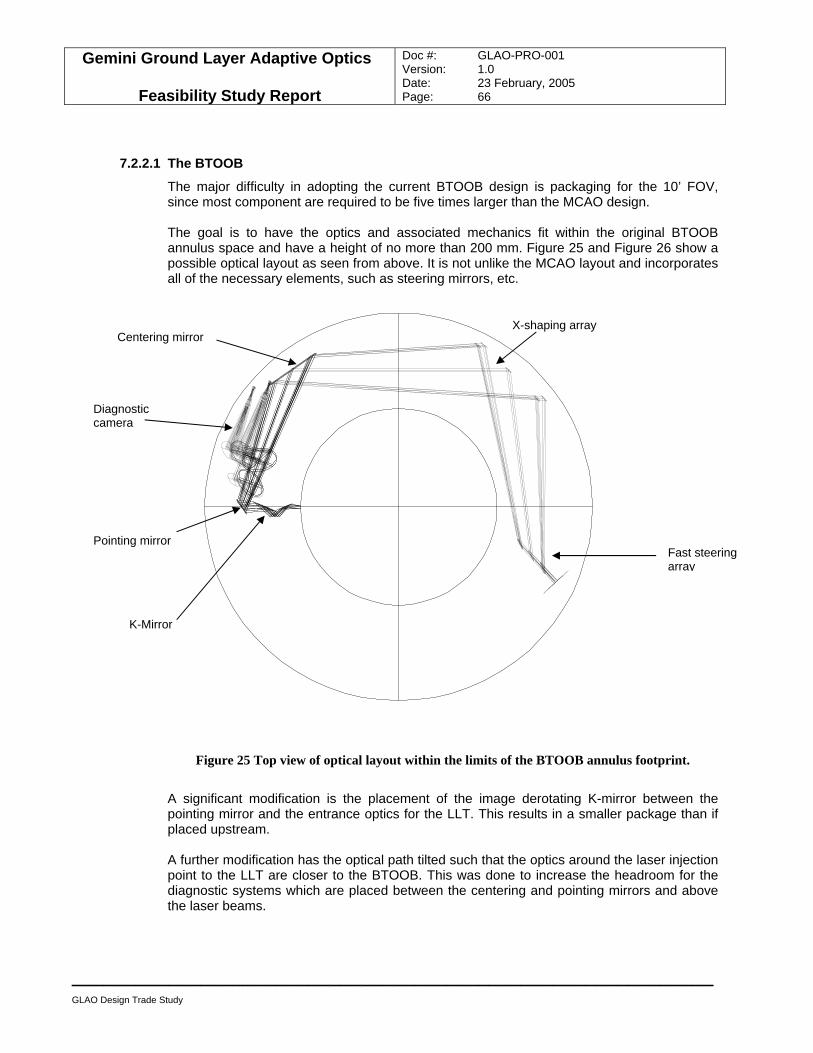
Gemini Ground Layer Adaptive Optics
Feasibility Study Report
Doc #: GLAO-PRO-001 Version: 1.0 Date: 23 February, 2005 Page: 66
____________________________________________________________
GLAO Design Trade Study
7.2.2.1 The BTOOB
The major difficulty in adopting the current BTOOB design is packaging for the 10’ FOV, since most component are required to be five times larger than the MCAO design.
The goal is to have the optics and associated mechanics fit within the original BTOOB annulus space and have a height of no more than 200 mm. Figure 25 and Figure 26 show a possible optical layout as seen from above. It is not unlike the MCAO layout and incorporates all of the necessary elements, such as steering mirrors, etc.
Figure 25 Top view of optical layout within the limits of the BTOOB annulus footprint.
A significant modification is the placement of the image derotating K-mirror between the pointing mirror and the entrance optics for the LLT. This results in a smaller package than if placed upstream. A further modification has the optical path tilted such that the optics around the laser injection point to the LLT are closer to the BTOOB. This was done to increase the headroom for the diagnostic systems which are placed between the centering and pointing mirrors and above the laser beams.
Centering mirror
Diagnostic camera
Pointing mirror
K-Mirror
X-shaping array
Fast steering array
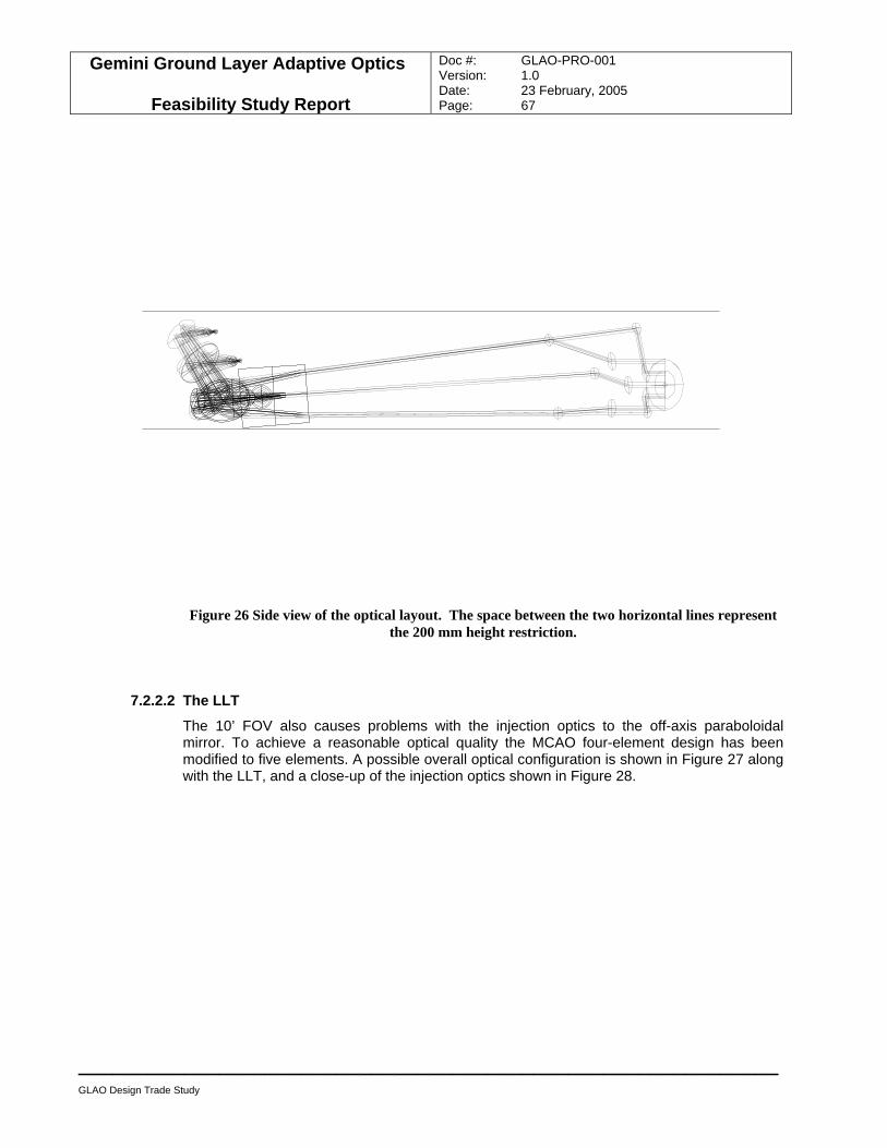
Gemini Ground Layer Adaptive Optics
Feasibility Study Report
Doc #: GLAO-PRO-001 Version: 1.0 Date: 23 February, 2005 Page: 67
____________________________________________________________
GLAO Design Trade Study
Figure 26 Side view of the optical layout. The space between the two horizontal lines represent the 200 mm height restriction.
7.2.2.2 The LLT
The 10’ FOV also causes problems with the injection optics to the off-axis paraboloidal mirror. To achieve a reasonable optical quality the MCAO four-element design has been modified to five elements. A possible overall optical configuration is shown in Figure 27 along with the LLT, and a close-up of the injection optics shown in Figure 28.
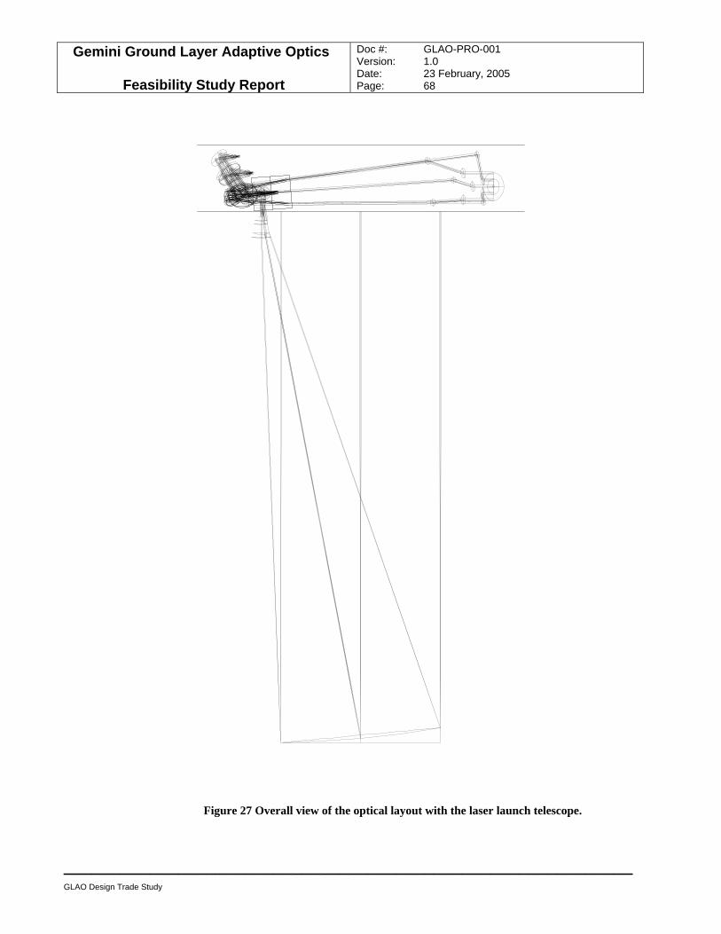
Gemini Ground Layer Adaptive Optics
Feasibility Study Report
Doc #: GLAO-PRO-001 Version: 1.0 Date: 23 February, 2005 Page: 68
____________________________________________________________
GLAO Design Trade Study
Figure 27 Overall view of the optical layout with the laser launch telescope.
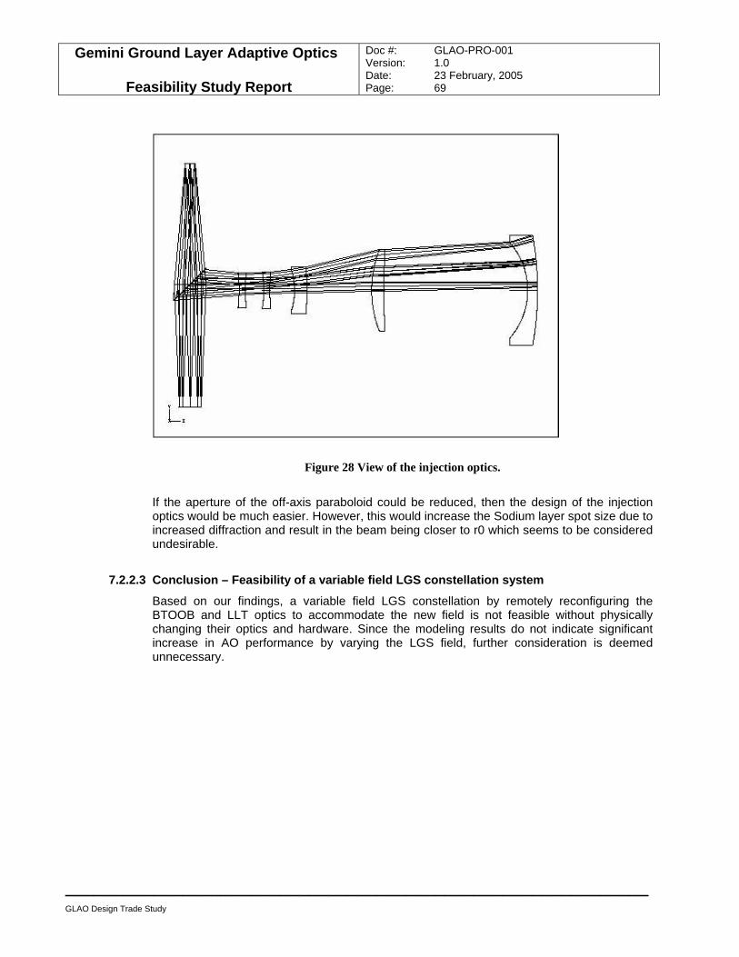
Gemini Ground Layer Adaptive Optics
Feasibility Study Report
Doc #: GLAO-PRO-001 Version: 1.0 Date: 23 February, 2005 Page: 69
____________________________________________________________
GLAO Design Trade Study
Figure 28 View of the injection optics.
If the aperture of the off-axis paraboloid could be reduced, then the design of the injection optics would be much easier. However, this would increase the Sodium layer spot size due to increased diffraction and result in the beam being closer to r0 which seems to be considered undesirable.
7.2.2.3 Conclusion – Feasibility of a variable field LGS constellation system
Based on our findings, a variable field LGS constellation by remotely reconfiguring the BTOOB and LLT optics to accommodate the new field is not feasible without physically changing their optics and hardware. Since the modeling results do not indicate significant increase in AO performance by varying the LGS field, further consideration is deemed unnecessary.
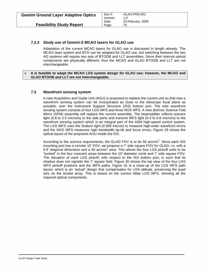
Gemini Ground Layer Adaptive Optics
Feasibility Study Report
Doc #: GLAO-PRO-001 Version: 1.0 Date: 23 February, 2005 Page: 70
____________________________________________________________
GLAO Design Trade Study
7.2.3 Study use of Gemini-S MCAO lasers for GLAO use Adaptation of the current MCAO lasers for GLAO use is discussed in length already. The MCAO laser system and BTO can be adapted for GLAO use, but switching between the two AO systems will require two sets of BTOOB and LLT assemblies. Since their internal optical components are physically different, thus the MCAO and GLAO BTOOB and LLT are not interchangeable.
• It is feasible to adapt the MCAO LGS system design for GLAO use; however, the MCAO and GLAO BTOOB and LLT are not interchangeable.
7.3 Wavefront sensing system A new Acquisition and Guide Unit (AGU) is proposed to replace the current unit so that new a wavefront sensing system can be incorporated as close to the telescope focal plane as possible, over the Instrument Support Structure (ISS) bottom port. The new wavefront sensing system consists of four LGS WFS and three NGS WFS. A new dichroic Science Fold Mirror (SFM) assembly will replace the current assembly. The beamsplitter reflects science light (0.8 to 2.5 microns) to the side ports and transmit WFS light (0.4 to 0.8 microns) to the wavefront sensing system which is an integral part of the ASM high-speed control system. The LGS WFS uses the Sodium light (0.589 micron) to measure high-order wavefront errors and the NGS WFS measures high bandwidth tip-tilt and focus errors. Figure 29 shows the optical layout of the proposed AGU inside the ISS. According to the science requirements, the GLAO FOV is to be 50 arcmin2. Since each ISS mounting port has a circular 10’ FOV, we propose a 7’ side square FOV for GLAO, i.e. with a 9.9’ diagonal dimension and a 50 arcmin2 area. This allows the four LGS pickoff units to be “tucked” in the four crescent areas between the 10’ diameter circle and 7’ side square FOV. The elevation of each LGS pickoff, with respect to the ISS bottom port, is such that its shadow does not vignette the 7’ square field. Figure 30 shows the top view of the four LGS WFS pickoff positions and the WFS paths. Figure 31 is a close-up of the LGS WFS path layout, which is an “actual” design that compensates for LGS altitude, preserving the pupil size on the lenslet array. This is based on the current Altair LGS WFS, showing all the required optical components.
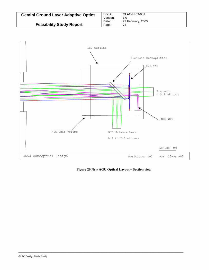
Gemini Ground Layer Adaptive Optics
Feasibility Study Report
Doc #: GLAO-PRO-001 Version: 1.0 Date: 23 February, 2005 Page: 71
____________________________________________________________
GLAO Design Trade Study
Figure 29 New AGU Optical Layout – Section view
GLAO Conceptual Design Positions: 1-2 JSP 25-Jan-05
500.00 MM
NIR Science beam
Transmit < 0.8 microns
0.8 to 2.5 microns
LGS WFS
NGS WFS
Dichroic Beamsplitter
ISS Outline
A&G Unit Volume
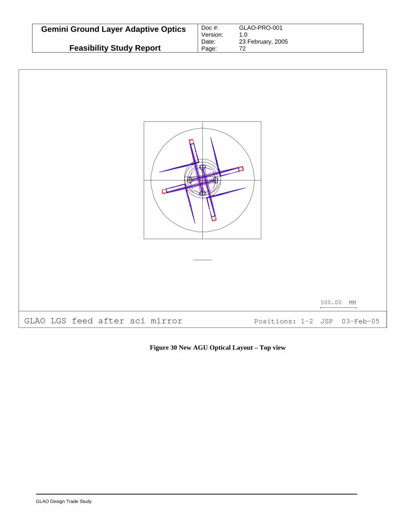
Gemini Ground Layer Adaptive Optics
Feasibility Study Report
Doc #: GLAO-PRO-001 Version: 1.0 Date: 23 February, 2005 Page: 72
____________________________________________________________
GLAO Design Trade Study
GLAO LGS feed after sci mirror Positions: 1-2 JSP 03-Feb-05
500.00 MM
Figure 30 New AGU Optical Layout – Top view
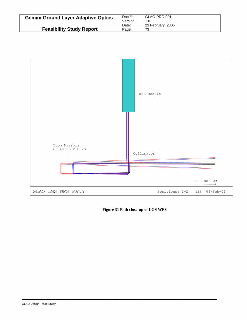
Gemini Ground Layer Adaptive Optics
Feasibility Study Report
Doc #: GLAO-PRO-001 Version: 1.0 Date: 23 February, 2005 Page: 73
____________________________________________________________
GLAO Design Trade Study
Figure 31 Path close-up of LGS WFS
GLAO LGS WFS Path Positions: 1-2 JSP 03-Feb-05
100.00 MM
Zoom Mirrors 85 km to 210 km
Collimator
WFS Module
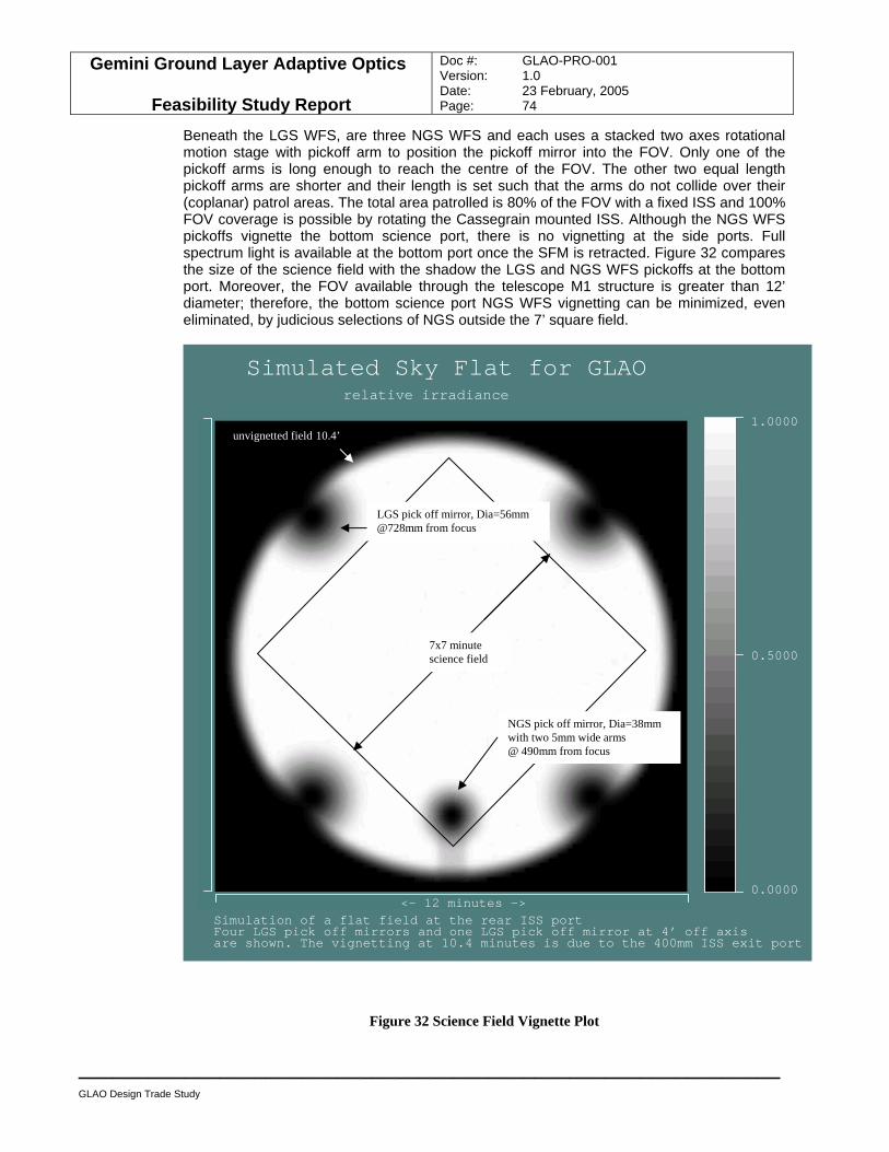
Gemini Ground Layer Adaptive Optics
Feasibility Study Report
Doc #: GLAO-PRO-001 Version: 1.0 Date: 23 February, 2005 Page: 74
____________________________________________________________
GLAO Design Trade Study
Beneath the LGS WFS, are three NGS WFS and each uses a stacked two axes rotational motion stage with pickoff arm to position the pickoff mirror into the FOV. Only one of the pickoff arms is long enough to reach the centre of the FOV. The other two equal length pickoff arms are shorter and their length is set such that the arms do not collide over their (coplanar) patrol areas. The total area patrolled is 80% of the FOV with a fixed ISS and 100% FOV coverage is possible by rotating the Cassegrain mounted ISS. Although the NGS WFS pickoffs vignette the bottom science port, there is no vignetting at the side ports. Full spectrum light is available at the bottom port once the SFM is retracted. Figure 32 compares the size of the science field with the shadow the LGS and NGS WFS pickoffs at the bottom port. Moreover, the FOV available through the telescope M1 structure is greater than 12’ diameter; therefore, the bottom science port NGS WFS vignetting can be minimized, even eliminated, by judicious selections of NGS outside the 7’ square field.
Figure 32 Science Field Vignette Plot
<- 12 minutes ->
0.0000
1.0000
0.5000
Simulated Sky Flat for GLAO
relative irradiance
Simulation of a flat field at the rear ISS port Four LGS pick off mirrors and one LGS pick off mirror at 4’ off axisare shown. The vignetting at 10.4 minutes is due to the 400mm ISS exit port
7x7 minute science field
unvignetted field 10.4’
LGS pick off mirror, Dia=56mm @728mm from focus
NGS pick off mirror, Dia=38mm with two 5mm wide arms @ 490mm from focus
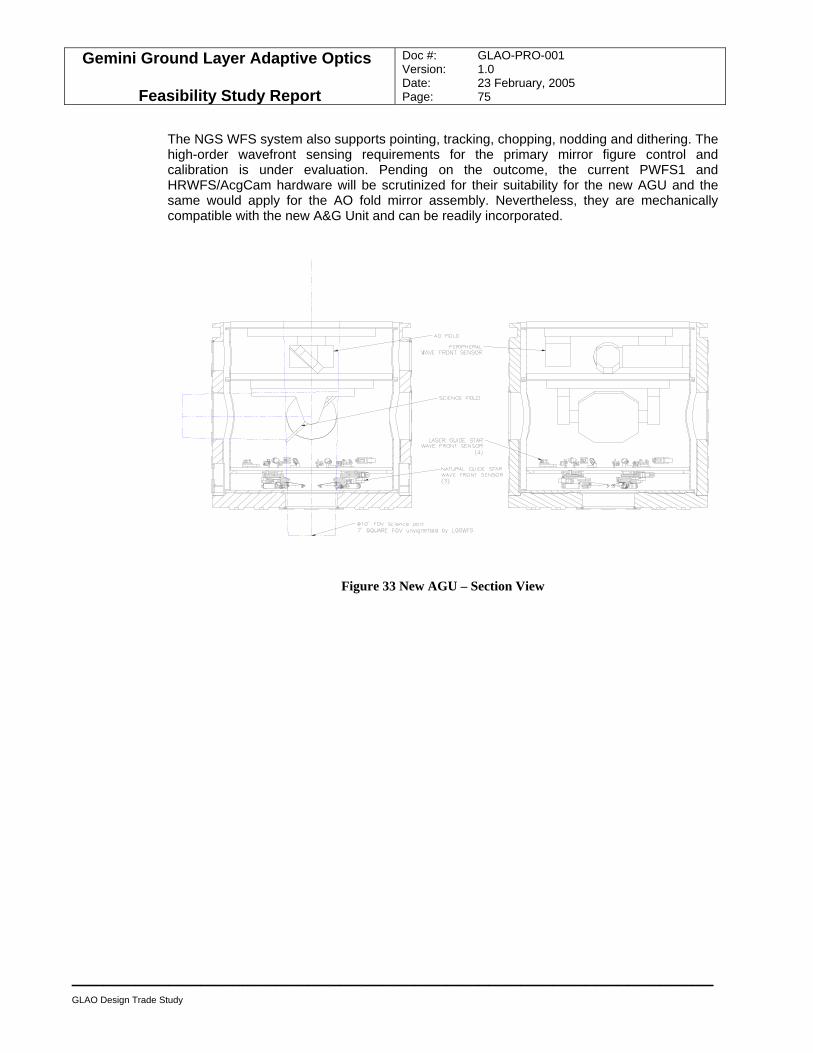
Gemini Ground Layer Adaptive Optics
Feasibility Study Report
Doc #: GLAO-PRO-001 Version: 1.0 Date: 23 February, 2005 Page: 75
____________________________________________________________
GLAO Design Trade Study
The NGS WFS system also supports pointing, tracking, chopping, nodding and dithering. The high-order wavefront sensing requirements for the primary mirror figure control and calibration is under evaluation. Pending on the outcome, the current PWFS1 and HRWFS/AcgCam hardware will be scrutinized for their suitability for the new AGU and the same would apply for the AO fold mirror assembly. Nevertheless, they are mechanically compatible with the new A&G Unit and can be readily incorporated.
Figure 33 New AGU – Section View
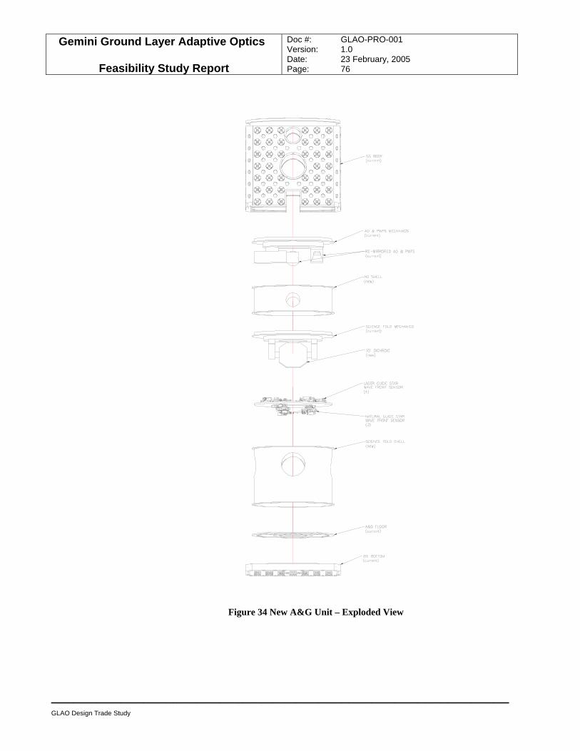
Gemini Ground Layer Adaptive Optics
Feasibility Study Report
Doc #: GLAO-PRO-001 Version: 1.0 Date: 23 February, 2005 Page: 76
____________________________________________________________
GLAO Design Trade Study
Figure 34 New A&G Unit – Exploded View
Gemini Ground Layer Adaptive Optics
Feasibility Study Report
Doc #: GLAO-PRO-001 Version: 1.0 Date: 23 February, 2005 Page: 77
____________________________________________________________
GLAO Design Trade Study
Figure 33 and Figure 34 show the optomechanical components of the new AGU. At the base of the new unit, over the science port, are three NGS WFS units; each patrols a portion of the 10’ science field3. Over them are four stationary LGS WFS units positioned at the edge of the 7’ square field. Over them is the new dichroic SFM assembly which delivers a 10’ diameter field to the side ports. In the figures, it is assumed that the current A&G Module 2 is modified to house the new SFM and mounted upside down. Over it is the current A&G Module 3 also mounted upside down and the AO fold mirror and the PWFS pickoff “flipped” to redirect the light. The order of the PWFS unit can be increased to suit the M1 mirror figuring and calibration requirements.
• A LGS and NGS WFS system that is fully compatible with the current telescope system can be implemented for side-port mounted NIR instruments and bottom-port mounted optical and narrow-field thermal IR instruments.
• There is no corresponding vignetting and emissivity issues. • There is no design issue with regard to the dichroic science fold mirror, see Appendix I.
3 Actually the patrol field can be as large as 12’ diameter.
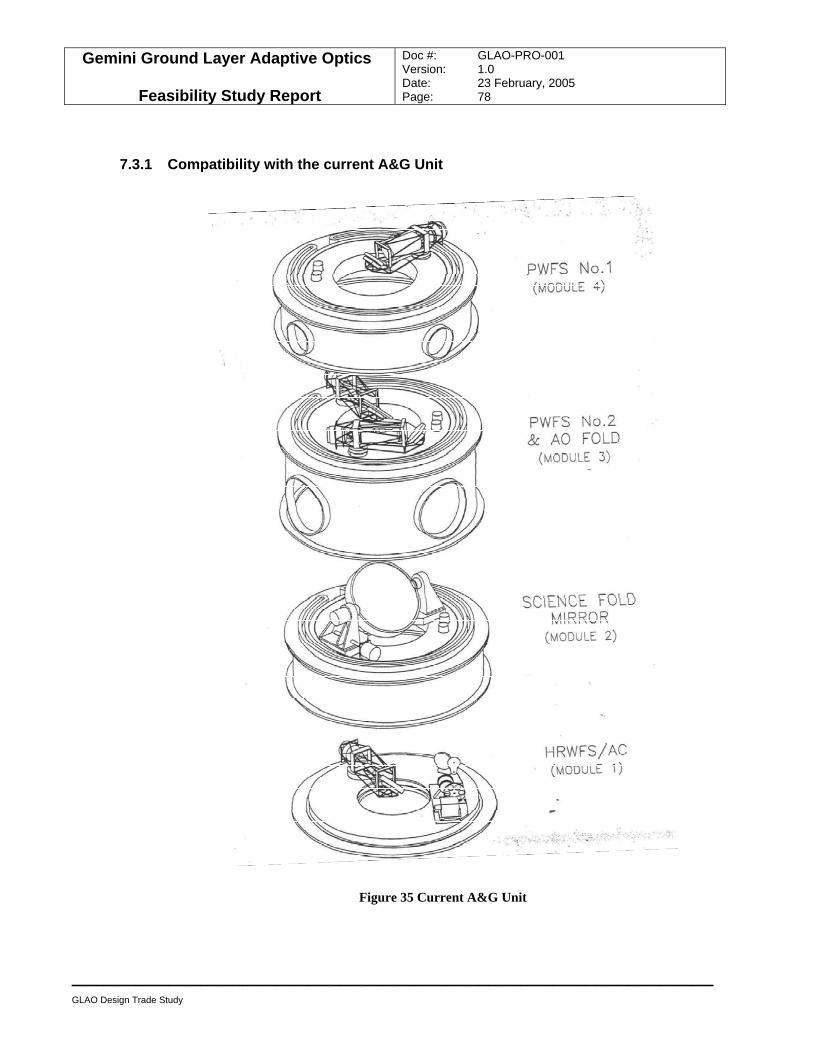
Gemini Ground Layer Adaptive Optics
Feasibility Study Report
Doc #: GLAO-PRO-001 Version: 1.0 Date: 23 February, 2005 Page: 78
____________________________________________________________
GLAO Design Trade Study
7.3.1 Compatibility with the current A&G Unit
Figure 35 Current A&G Unit
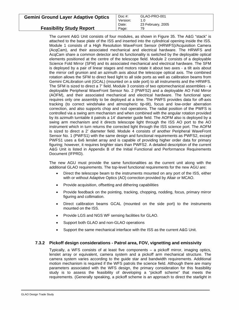
Gemini Ground Layer Adaptive Optics
Feasibility Study Report
Doc #: GLAO-PRO-001 Version: 1.0 Date: 23 February, 2005 Page: 79
____________________________________________________________
GLAO Design Trade Study
The current A&G Unit consists of four modules, as shown in Figure 35. The A&G “stack” is attached to the base plate of the ISS and inserted into the cylindrical opening inside the ISS. Module 1 consists of a High Resolution WaveFront Sensor (HRWFS)/Acquisition Camera (AcqCam), and their associated mechanical and electrical hardware. The HRWFS and AcqCam share a common detector and its functionality is switched by the deployable optical elements positioned at the centre of the telescope field. Module 2 consists of a deployable Science Fold Mirror (SFM) and its associated mechanical and electrical hardware. The SFM is deployed by a pair of linear stages and motors rotate it about two axes - a tilt axis about the mirror cell grunion and an azimuth axis about the telescope optical axis. The combined rotation allows the SFM to direct feed light to all side ports as well as calibration beams from Gemini CALibration unit (GCAL) (mounted on a side port) to all instruments and the HRWFS. The SFM is sized to direct a 7’ field. Module 3 consists of two optomechanical assemblies - a deployable Peripheral WaveFront Sensor No. 2 (PWFS2) and a deployable AO Fold Mirror (AOFM), and their associated mechanical and electrical hardware. The functional spec requires only one assembly to be deployed at a time. The PWFS provides data for off-axis tracking (to correct windshake and atmospheric tip-tilt), focus and low-order aberration correction, and also supports chop and nod operations. The radial position of the PWFS is controlled via a swing arm mechanism and when combined with the angular rotation provided by its azimuth turntable it patrols a 14’ diameter guide field. The AOFM also is deployed by a swing arm mechanism and it directs telescope light through the ISS AO port to the AO instrument which in turn returns the corrected light through the ISS science port. The AOFM is sized to direct a 2’ diameter field. Module 4 consists of another Peripheral WaveFront Sensor No. 1 (PWFS1) with the same design and functional requirements as PWFS2, except PWFS1 uses a 6x6 lenslet array and is capable of providing higher order data for primary figuring; however, it requires brighter stars than PWFS2. A detailed description of the current A&G Unit is listed in Appendix B of the Initial Functional and Performance Requirements Document (IFPRD). The new AGU must provide the same functionalities as the current unit along with the additional GLAO requirements. The top-level functional requirements for the new AGU are:
• Direct the telescope beam to the instruments mounted on any port of the ISS, either with or without Adaptive Optics (AO) correction provided by Altair or MCAO.
• Provide acquisition, offsetting and dithering capabilities
• Provide feedback on the pointing, tracking, chopping, nodding, focus, primary mirror figuring and collimation.
• Direct calibration beams GCAL (mounted on the side port) to the instruments mounted on the ISS.
• Provide LGS and NGS WF sensing facilities for GLAO.
• Support both GLAO and non-GLAO operations
• Support the same mechanical interface with the ISS as the current A&G Unit.
7.3.2 Pickoff design considerations - Patrol area, FOV, vignetting and emissivity Typically, a WFS consists of at least five components – a pickoff mirror, imaging optics, lenslet array or equivalent, camera system and a pickoff arm mechanical structure. The camera system varies according to the guide star and bandwidth requirements. Additional motion mechanism is required if the WFS patrols the science field. Although there are many parameters associated with the WFS design, the primary consideration for this feasibility study is to assess the feasibility of developing a “pickoff scheme” that meets the requirements. (Generally speaking, a pickoff scheme is an approach to direct the starlight in
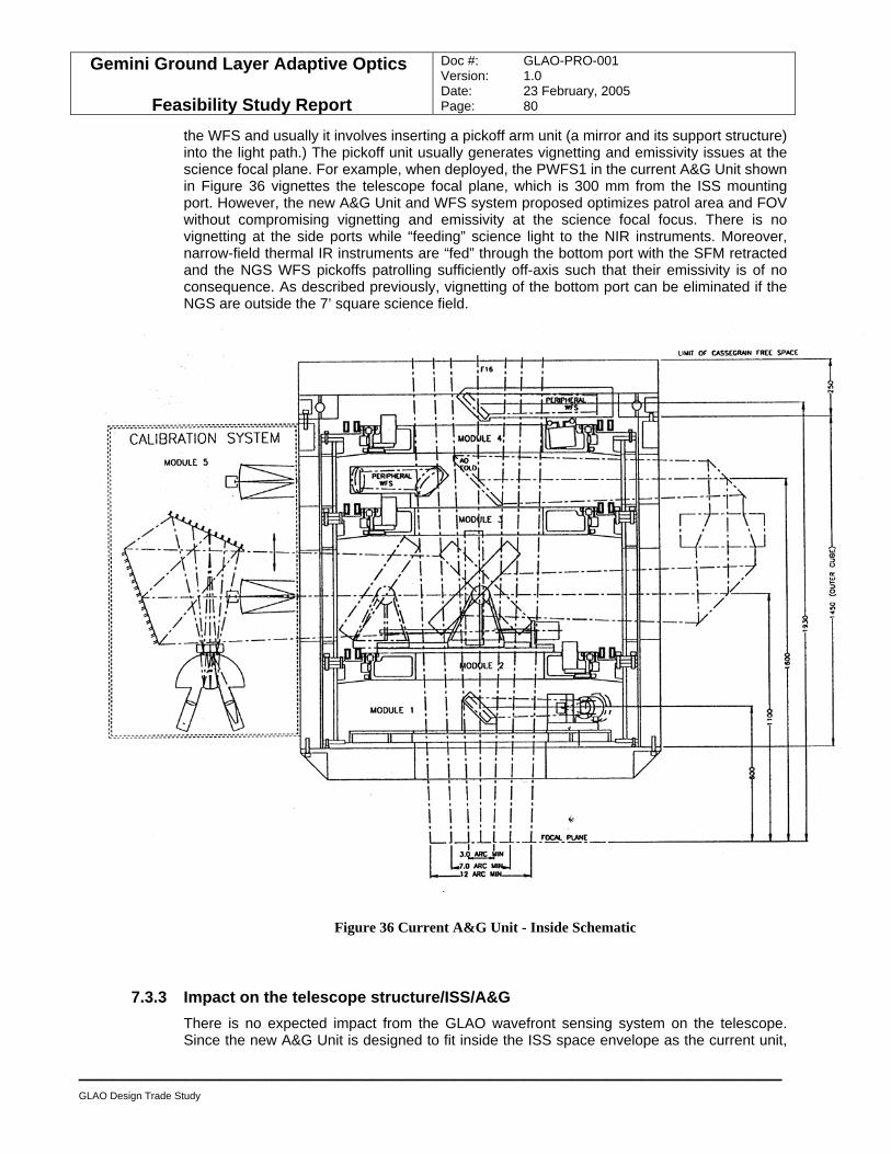
Gemini Ground Layer Adaptive Optics
Feasibility Study Report
Doc #: GLAO-PRO-001 Version: 1.0 Date: 23 February, 2005 Page: 80
____________________________________________________________
GLAO Design Trade Study
the WFS and usually it involves inserting a pickoff arm unit (a mirror and its support structure) into the light path.) The pickoff unit usually generates vignetting and emissivity issues at the science focal plane. For example, when deployed, the PWFS1 in the current A&G Unit shown in Figure 36 vignettes the telescope focal plane, which is 300 mm from the ISS mounting port. However, the new A&G Unit and WFS system proposed optimizes patrol area and FOV without compromising vignetting and emissivity at the science focal focus. There is no vignetting at the side ports while “feeding” science light to the NIR instruments. Moreover, narrow-field thermal IR instruments are “fed” through the bottom port with the SFM retracted and the NGS WFS pickoffs patrolling sufficiently off-axis such that their emissivity is of no consequence. As described previously, vignetting of the bottom port can be eliminated if the NGS are outside the 7’ square science field.
Figure 36 Current A&G Unit - Inside Schematic
7.3.3 Impact on the telescope structure/ISS/A&G There is no expected impact from the GLAO wavefront sensing system on the telescope. Since the new A&G Unit is designed to fit inside the ISS space envelope as the current unit,
Gemini Ground Layer Adaptive Optics
Feasibility Study Report
Doc #: GLAO-PRO-001 Version: 1.0 Date: 23 February, 2005 Page: 81
____________________________________________________________
GLAO Design Trade Study
the wavefront sensing system has no direct impact on the telescope and ISS, structurally speaking.
7.3.4 Intermediate A&G implementation concept A possible intermediate phase involving limited modification of the current A&G unit, but providing full LGS GLAO at the current upward-looking port (only), has also been studied. This would re-use the GLAO LGS and NGS WFSs that are required in the final implementation phase, and would also require the deployment of the ASM. Details of this option are provided in Appendix G. Proposed annular science fold mirror.
7.3.5 Impact on operation and compatibility issues As mentioned, the “transferability” of the components in Module 1, 3 and 4 of the current A&G Unit will be assessed for the new unit. If suitable, they will be adapted for the AO fold mirror and high-order WFS required. The requirements for an integrated acquisition camera will be evaluated as well. The requirements for supporting chopping, dithering and nodding using with the three NGS WFS will be formalized and incorporated into the next design cycle. Likely, the basic requirements are:
• Dithering/nodding with AO closed loop correction with amplitude of 5 arcsec at TBD Hz.
• Chopping with guiding at either one end or both ends of the chop with amplitude of 15 arcsec at TBD Hz (requirement) and of 30 arcsec at TBD Hz (goal).
• The new AGU design and telescope system are fully backward compatible with the
functionalities and operations of the existing A&G Unit. • The AGU design has no impact on the telescope and ISS structurally.
7.4 Rayleigh beacon laser system While the great majority of the astronomical AO community is focused on the development of Na LGS as the beacon of choice, in the particular case of GLAO, low-level Rayleigh beacons offer a practical and cost-effective alternative. They also offer the distinct advantage that well-engineered lasers exist and can be ordered as stock items from a number of manufacturers. In addition, Rayleigh beacons do not suffer from brightness fluctuations caused by variations in scatterer column density, and are not subject to the height uncertainty that renders focus measurements from Sodium beacons uncertain. The price to be paid is the need for a dynamic refocus scheme to avoid perspective elongation, since the integration time required to yield a sufficiently strong signal for reasonable laser power implies a pulse pathlength greatly exceeding Gemini’s depth of focus.
7.4.1 Laser system The laser system would require one 15 W doubled-YAG laser per beacon. Laser heads of the type required are not large, and all four could readily be accommodated in a single box attached to the side of the telescope structure, thereby minimizing the complexity of the feed optics to get the beams onto the telescope. Power supplies, cooling, and diagnostics would be located remotely in a temperature controlled environment.
Gemini Ground Layer Adaptive Optics
Feasibility Study Report
Doc #: GLAO-PRO-001 Version: 1.0 Date: 23 February, 2005 Page: 82
____________________________________________________________
GLAO Design Trade Study
7.4.2 BTO/BTOOB/LLT Section 7.2 specifies an LGS system modeled on the current Gemini systems, but differing in the number of guide stars (4) and the larger field size, due to the larger LGS asterism requirements. The differences in BTO requirements between the baseline Sodium laser implementation of GLAO and the Gemini-S MCAO system consist only of the reduced number of guide stars for GLAO (4 instead of 5) and any general relaxation of system error budgets due to the reduction in delivered image quality for GLAO as opposed to MCAO. Such relaxations are likely to be very modest when propagated to the BTO and certainly not sufficient to justify the design effort and risk of departing from the MCAO design in order to gain cost reductions. The baseline design concept is therefore to copy the MCAO BTO system, the feasibility of which is taken as a given. In practice, the use of the Gemini-S MCAO BTO design on Gemini-N would simply amount to a modification of the existing Gemini-N BTO installation to deal with four laser beacons instead of one. This is because the Southern design closely follows the Northern where possible. The Gemini-S BTO design contains the optics which produces the X-shaped LGS constellation for MCAO, and this of course would need to be incorporated. This design would, of course, require modification for 4 LGS instead of 5 but this should not present issues of feasibility. The other required modification of the Northern installation would be to incorporate the Southern system for rotating the LGS constellation with telescope zenith angle. All other specifications (throughput, beam quality, polarisation, steering, diagnostics, shuttering and control) remain the same as would consequent space, weight and thermal budgets. The Northern system for dithering would not actually be required for GLAO but should be left unaffected for continued compatibility with Altair. Both the Gemini-N and Gemini-S designs are specifically intended for use with a Sodium laser. For use with a Rayleigh beacon laser two changes are anticipated. Firstly, there must be a change of the wavelength of all dielectric mirrors from 589nm to the selected Rayleigh wavelength. This should not have any effect on feasibility, and no significant effect on cost or operation of the BTO. Secondly, the design must ensure that all the components can deal with the increased peak power of a pulsed laser. This requirement should not in itself affect any of the current component choices. It is conceivable that some modifications may be desirable in the light of operational experience with the MCAO LGS system, but such considerations are beyond the timescale and scope of the present study.
7.4.3 WFS Five separate Shack-Hartmann sensors would be matched one-to-one to the LGS. The ideal devices already exist: the 80 x 80 pixel E2V CCD39. The individual lasers beams are naturally linearly polarized. To enforce circular polarization on the sky, a quarter wave plate would be used, with probably one each per beacon. Gating would then very efficiently be done with quarter wave plates, to restore linear polarization, and Pockels cells in front of each WFS head. Circular polarization on the sky means that one need not be concerned about changes in the angle with field rotation. There is no difficulty in gating the small field of view needed for each beacon with readily available Pockels cells. The étendue for a cell with 1 cm2 aperture is 4´10-8 m2, matching a 6’ diameter field at Gemini. Each beacon would be analyzed with a 10 x 10 array of 0.8 m subapertures. The CCD pixels would be binned on-chip 3 x 3, with each spot falling on a quad cell of 4 super pixels. In this way, degradation of the slope transfer function by charge diffusion is minimized. Because these WFS heads would always be used with LGS of constant brightness, there is no need
Gemini Ground Layer Adaptive Optics
Feasibility Study Report
Doc #: GLAO-PRO-001 Version: 1.0 Date: 23 February, 2005 Page: 83
____________________________________________________________
GLAO Design Trade Study
for provision of different lenslet arrays. The optical design of the heads can therefore be very simple and robust.
7.4.4 Dynamic refocus To avoid the need for very powerful lasers, the range gate for the Rayleigh beacons must be extended well beyond the depth of focus of the telescope. Perspective elongation of the WFS spots at the edge of the pupil would therefore be unacceptable unless it is actively compensated. A scheme to do so through dynamic refocus of the telescope has been demonstrated at the MMT, and has proven to be very robust. In this technique, a high-Q mechanical resonator drives the refocusing mirror, while also triggering pulses from the lasers, and the WFS shutter. After several iterations, a mechanical design has been proven, with hundreds of hours of operation without failure, as demonstrated by a Q that remains constant with time. The whole dynamic refocus optical system is cheap to produce and robust in operation, and therefore represents a modest price to pay for the huge savings in the cost of the lasers.
• It is also feasible to implement a Rayleigh beacons LGS system since the associated hardware and technology for dynamic refocus WFS are proven.
Gemini Ground Layer Adaptive Optics
Feasibility Study Report
Doc #: GLAO-PRO-001 Version: 1.0 Date: 23 February, 2005 Page: 84
____________________________________________________________
GLAO Design Trade Study
7.5 Summary of design trade study In the design trade study, the top-level functional requirements for three major subsystems (LGS, wavefront sensing and ASM) are derived from the science requirements and current Gemini subsystem specifications. The suitability of the telescope subsystems (MCAO LGS system, A&G Unit and M2 assembly) is assessed, and current transferable components are adapted for the GLAO system. Based on our assessment, the planned LGS system is readily adaptable to GLAO use with the BTOOB and LLT optical components modified for the larger LGS field. A new AGU is required for the GLAO LGS and NGS WFS, and the dichroic SFM. It is possible that the current AO fold mirror, PWFS1 and HRWFS assemblies are reusable in the new unit pending further development work. The current M2 assembly is replaced by an ASM system with minimal changes to the telescope top end structure.
• A GLAO system for the Gemini telescope is feasible, using existing design and hardware, with minimal impact on the telescope system.
Gemini Ground Layer Adaptive Optics
Feasibility Study Report
Doc #: GLAO-PRO-001 Version: 1.0 Date: 23 February, 2005 Page: 85
____________________________________________________________
Interface with Gemini observatory system
8.0 Interface with Gemini observatory system
8.1 Overview The Gemini observatory to GLAO interface requirements are listed in Appendix C. ICD 1.1x GLAO Interface Control Documents of the Initial Functional and Performance Requirements Document. The purpose of this section is to identify and list the relevant physical interfaces, except for software, under four categories: mechanical; electrical/electronics; new services; and control & monitoring. Due to the preliminary phase of this study, many physical interfaces required more clarify, investigation and development than the scope and time allowed. When information is insufficient, the corresponding interface listed becomes a placeholder for future work.
8.2 ICD N2 matrix The top-level GLAO to telescope system interfaces are summarized in the ICD N2 matrix shown in Figure 37 which includes all possible top-level interfaces whether they are physical or software, direct or indirect, external or internal.
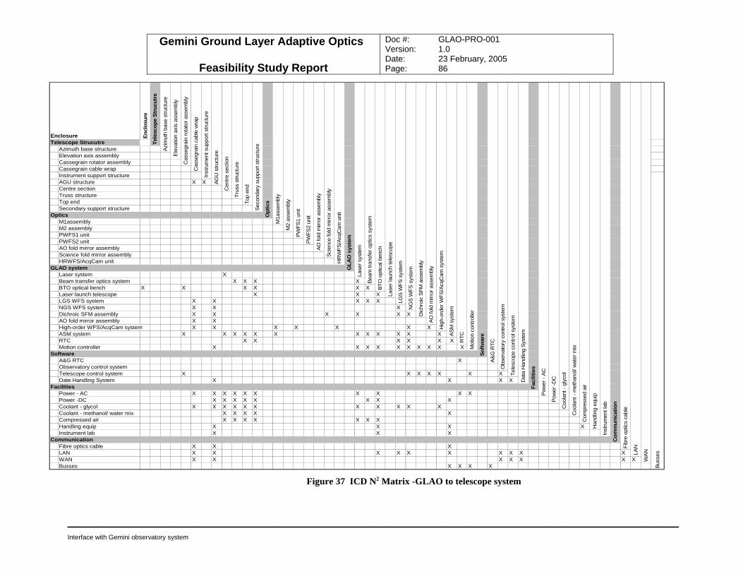
Gemini Ground Layer Adaptive Optics
Feasibility Study Report
Doc #: GLAO-PRO-001 Version: 1.0 Date: 23 February, 2005 Page: 86
_________________________________________________________________________________
Interface with Gemini observatory system
Enclosure Encl
osur
eTelescope Strucutre
Azimuth base structure Elevation axis assemblyCassegrain rotator assemblyCassegrain cable wrapInstrument support structureAGU structure X XCentre sectionTruss structureTop endSecondary support structure
OpticsM1assemblyM2 assemblyPWFS1 unitPWFS2 unitAO fold mirror assemblyScience fold mirror assemblyHRWFS/AcqCam unit
GLAO systemLaser system XBeam transfer optics system X X X XBTO optical bench X X X X X XLaser launch telescope X X XLGS WFS system X X X X XNGS WFS system X X XDichroic SFM assembly X X X X X XAO fold mirror assembly X XHigh-order WFS/AcqCam system X X X X X X XASM system X X X X X X X X X X X XRTC X X X X X XMotion controller X X X X X X X X X X
SoftwareA&G RTC XObservatory control systemTelescope control system X X X X X X XDate Handling System X X X X
FacilitiesPower - AC X X X X X X X X X XPower -DC X X X X X X X XCoolant - glycol X X X X X X X X X X XCoolant - methanol/ water mix X X X X XCompressed air X X X X X X XHandling equip X X X XInstrument lab X X X
CommunicationFibre optics cable X X XLAN X X X X X X X X X XWAN X X X X X X XBusses X X X X
Seco
ndar
y su
ppor
t stru
ctur
e
Top
end
M2
asse
mbl
y
PWFS
1 un
it
M1a
ssem
bly
Opt
ics
Inst
rum
ent s
uppo
rt st
ruct
ure
AGU
stru
ctur
e
Cen
tre s
ectio
n
Trus
s st
ruct
ure
PWFS
2 un
it
AO
fold
mirr
or a
ssem
bly
Sci
ence
fold
mirr
or a
ssem
bly
HR
WFS
/Acq
Cam
uni
t
Tele
scop
e St
rucu
tre
Azim
uth
base
stru
ctur
e
Cas
segr
ain
rota
tor a
ssem
bly
Cas
segr
ain
cabl
e w
rap
Ele
vatio
n ax
is a
ssem
bly
GLA
O s
yste
m
Lase
r sys
tem
Bea
m tr
ansf
er o
ptic
s sy
stem
BTO
opt
ical
ben
ch
Lase
r lau
nch
tele
scop
e
LGS
WFS
sys
tem
NG
S W
FS s
yste
m
Dic
hroi
c SF
M a
ssem
bly
AO
fold
mirr
or a
ssem
bly
Hig
h-or
der W
FS/A
cqC
am s
yste
m
AS
M s
yste
m
Softw
are
RTC
Mot
ion
cont
rolle
r
Pow
er -D
C
Coo
lant
- gl
ycol
Coo
lant
- m
etha
nol/
wat
er m
ix
Obs
erva
tory
con
trol s
yste
m
Tele
scop
e co
ntro
l sys
tem
Dat
a H
andl
ing
Sys
tem
Faci
litie
s
A&G
RTC
Bus
ses
Fibr
e op
tics
cabl
e
LAN
WA
N
Com
pres
sed
air
Han
dlin
g eq
uip
Inst
rum
ent l
ab
Com
mun
icat
ion
Pow
er -
AC
Figure 37 ICD N2 Matrix -GLAO to telescope system
Gemini Ground Layer Adaptive Optics
Feasibility Study Report
Doc #: GLAO-PRO-001 Version: 1.0 Date: 23 February, 2005 Page: 87
_____________________________________________________________ Interface with Gemini observatory system
8.3 Interface requirements
8.3.1 ASM to telescope The current M2 assembly consists of the secondary mirror, deployable baffles, X-Y position motion stage, tip-tilt and focus motion system and their control electronics. It will be replaced by an ASM assembly consisting of a deformable mirror assembly and possibly a new hexapod system (or the current 5-axis motion stages) and their control electronics; a high-speed monitoring and control system governs AO and non-AO mode, and also mitigates the (structural) dynamic coupling between the ASM and telescope top end. The ASM assembly uses the same mechanical interface as the M2 assembly and depending on the ASM configuration options, as discussed in Section 7.0, the electronics and electrical system will vary. Nevertheless, upgrade is required for the current data handling, power and cooling systems.
8.3.1.1 Mechanical
• Mechanical interface – secondary support structure M2 assembly mounting flange
• Mass and Centre of Gravity (CofG) – TBD (Compare the mass of ASM and M2 assembly)
• Space Envelope – listed in the IFPRD
• Cooling and heat dissipation – TBD depending on ASM option
• Handling and installation – vary depending on ASM option, nevertheless should be similar to the current M2 assembly
8.3.1.2 Electrical/Electronics
• Power – TBD depending on ASM option
• Cabling – Two pairs new of 2 Gbit/s fibers for real-time and diagnostic data transfer, and TBD on reusing the existing M2 assembly cables for the ASM option chosen
• Electronic location – secondary support structure and top ring, TBD depending on ASM option
8.3.1.3 New Services
• AC power - +/- 15 V @ 60 A, +12 V @ 10 A
• Liquid coolant system capable to deliver 50/50 methanol/water mixture at 18-25 liters/minute (recommended)
• On-site off-telescope vertical optical bench and 4D interferometer for ASM mirror calibration
Gemini Ground Layer Adaptive Optics
Feasibility Study Report
Doc #: GLAO-PRO-001 Version: 1.0 Date: 23 February, 2005 Page: 88
_____________________________________________________________ Interface with Gemini observatory system
8.3.1.4 Control and monitoring
Much of the control and monitoring requirements are handled internally between the software components Instrument Sequencer (IS) and WaveFront Control System (WFCS).
• External Software interfaces – TBD, to be supported by IS for both AO and non-AO mode
8.3.2 BTO, BTOOB and LLT to telescope The interfaces described in this section are based on the assumption that the telescope has been upgraded for LGS operation with a complete LGS system including NdYAG laser system, BTO, BTOOB and LLT. However, the GLAO laser system interface is not considered below.
8.3.2.1 Mechanical
• Mechanical interface – no change
• Mass and Centre of Gravity (CofG) – TBD (Note: lager optical components are required for the lager LGS field)
• Space Envelope – no change
• Cooling and heat dissipation – no change
• Handling and installation – no change
8.3.2.2 Electrical/Electronics
• Power – no change
• Cabling – no change
• Electronic location – no change
8.3.2.3 New Services
Four lasers are required by GLAO, where five are available from MCAO and one is available from Altair LGS system. Incidentally, a five laser MCAO-like NdYAG laser will accommodate both GLAO and Altair LGS operational requirement.
8.3.2.4 Control and monitoring
The control and monitoring requirements are unchanged. The interfaces between the LGS and their WFS are handled internally between the software components Component Controller (CC) and WFCS via the IS.
• External software interfaces – TBD, to be supported by IS to distinguish between AO and non-AO mode
Gemini Ground Layer Adaptive Optics
Feasibility Study Report
Doc #: GLAO-PRO-001 Version: 1.0 Date: 23 February, 2005 Page: 89
_____________________________________________________________ Interface with Gemini observatory system
8.3.3 WFS to ISS
8.3.3.1 Description of NGS and LGS WFS
The LGS WFS are fixed in the science field; however, they required motion stages for zoom and collimation in order to accommodate the variations in the Sodium layer height. They are not used for non-AO operation. The NGS WFS patrols the science field using a stacked two-axis rotational stage with a mirror mounted at the tip of the pickoff arm. Both LGS and NGS WFS are mounted inside the new A&G Unit along with the new dichroic beamsplitter science fold mirror, an AO fold mirror and an High-Order WFS/AcqCam. The new AGU has the same mechanical interface with the ISS as the current A&G Unit.
8.3.3.2 WFS to AGU
8.3.3.2.1 Mechanical
• Mechanical interface – internal to the new AGU
• Mass and Centre of Gravity (CofG) – internal to the new AGU
• Space Envelope – internal to the new AGU
• Cooling and heat dissipation – listed in the IFPRD
• Handling and installation – internal to the new AGU
8.3.3.2.2 Electrical/Electronics
• Power – TBD
• Cabling – TBD on reusing the existing cables in the Cassegrain rotator
• Electronics – TBD, electronics for the new WFS and science fold mirror
• Electronic location – no change, GCAL ISS side mounting port
8.3.3.2.3 New Services Extra power, cabling and cooling are required for the extra electronics, TBD.
8.3.3.2.4 Control and monitoring The control and monitoring requirements are handled internally between the software components IS, CC and WFCS for AO operation.
• External software interfaces – TBD, to be supported by IS for AO mode
• New software interfaces – TBD for non-AO mode (Note: LGS WFS is no used and currently all NGS WFS are under the telescope Telescope Control System (TCS) command directly.)
8.3.3.3 WFS to ISS
There is no direct physical interface between the GLAO WFS and ISS, except the possibility of routing cabling through the rectangular “mouse-hole” at the bottom of the GCAL ISS port.
Gemini Ground Layer Adaptive Optics
Feasibility Study Report
Doc #: GLAO-PRO-001 Version: 1.0 Date: 23 February, 2005 Page: 90
_____________________________________________________________ Interface with Gemini observatory system
8.3.3.4 WFS to M1 mirror cell and baffle tube
One of the earlier GLAO WFS packaging concepts uses the free-space inside the central volume of the M1 mirror cell below the baffle tube; however, the current concept proposed does not. Therefore, no physical interface is required.
Gemini Ground Layer Adaptive Optics
Feasibility Study Report
Doc #: GLAO-PRO-001 Version: 1.0 Date: 23 February, 2005 Page: 91
_____________________________________________________________ Modification requirements
9.0 Modification requirements
9.1 Telescope structure Modification to the telescope structure, between the laser system to telescope truss, telescope truss to top end, top end and SSS, is expected to be minimal. Depending on the ASM options chosen, placement of electronic enclosures might require minor structural modifications for their mounting. Also, the laser system and BTO enclosed conduit will be modified to accommodate four laser beams.
9.2 M2 assembly If the ASM option 2 is chosen, the new ASM assembly will attach to the 5-axis motion stage of the M2 assembly. This might require modification to the mounting interface as well as the stages due to the higher ASM mass.
9.3 A&G unit and WF sensing A new AGU design is required to meet the GLAO wavefront sensing configuration.
9.4 ISS No major modification is expected to the ISS since the new AGU will comply with the current ISS to A&G mechanical interface requirements. There might be minor modifications due to new cabling and services requirements.
9.5 M1 mirror cell and baffle tube At the beginning of the feasibility study, the actual telescope FOV available inside the A&G Unit was uncertain and the M1 mirror cell baffle tube was alleged to vignette the FOV. After a detailed investigation during the site visit, the actual FOV was determined with confirmation that the baffle tube does not vignette. Therefore, no modification is required.

Gemini Ground Layer Adaptive Optics
Feasibility Study Report
Doc #: GLAO-PRO-001 Version: 1.0 Date: 23 February, 2005 Page: 95
_____________________________________________________________
11.0 Conclusions and recommendations
Through science case analyses, AO modeling and simulations, this feasibility study clearly illustrates the scientific potential of a GLAO system for the Gemini telescopes. Moreover, the feasibility of implementing such a GLAO system on Gemini has been established through engineering analyses and technology studies. The GLAO science case clearly indicates that there will be a tremendous efficiency gain due both to the larger FOV and to the AO-corrected image quality improvements. The AO performance gain is verified by modeling studies using both analytical codes and Monte Carlo simulations from the three partner groups. The modeling tools have been validated against each other and independently with other modeling codes. The modeling tools allowed efficient and effective trade studies of the system parameters to be carried out within the GLAO design space. The proposed GLAO architecture in this report has been optimized in terms of scientific performance and competitiveness, while minimizing the impact to the existing telescope system, and minimizing technological risk entailed in implementing a new adaptive secondary mirror and new wavefront sensing systems. In our opinion, there is no technical difficulty in completing the design and implementation of the three major GLAO systems described in this report once their functionalities and specifications are formally established in more detail. With the help of Gemini technical staff, we have made great progress in collecting and documenting technical information of the relevant Gemini systems. However, given the limited scope and restricted timeline of the feasibility study, we believe that more work is required to develop a comprehensive understanding of the complex opto-mechanical, electrical, electronic, and software interfaces of entire telescope system as they pertain to a GLAO conversion. We have made a good start and laid the foundation of a GLAO system optimized for the Gemini telescope through the following fundamental scientific and technical documents that were developed as part of this feasibility study:
• Science case and science requirements documents
• Initial Operational Concepts Definition Document (IOCDD)
• Initial Functional and Performance Requirements Document (IFPRD)
• GLAO Interface Control Document (ICD) list These documents are attached as appendices to this report.
11.1 Future works In effect, the documents above form the basis for a Gemini GLAO system and indicate directions for further development. Scientifically, the operational concepts and the functional requirements of the GLAO specific instruments (e.g. Wide field NIR imager and d-IFU spectrograph) need to be developed in more detail in order to refine the overall GLAO design requirements since the GLAO “facility” and its instruments must operate as a integrated system. An initial study of a potential widefield imager by INO is attached as an Appendix to this report. Feasibility studies for “MOAO” deployable IFU spectrographs are just beginning for TMT and results of those studies should be very relevant for Gemini GLAO. It was unfortunate that we were unable to carry out a comparison of GLAO performance between Gemini-N and Gemini-S due to the lack of adequate atmospheric profile data for the northern telescope. This lack of quantitative performance data will become critical if other
Gemini Ground Layer Adaptive Optics
Feasibility Study Report
Doc #: GLAO-PRO-001 Version: 1.0 Date: 23 February, 2005 Page: 96
_____________________________________________________________ Conclusions and recommendations
considerations continue to favour installation of GLAO on the Gemini-N telescope. It is encouraging that more atmospheric surveys are currently being planned at the Mauna Kea summit, and a proper comparison study should be carried out as soon as possible. This will establish the ultimate scientific gains of a GLAO system for Gemini. Although the ASM is a mature technology that has been demonstrated successfully on the MMT telescope, the ASM for Gemini GLAO requires different actuators, a larger air gap for chopping, and careful electronic packaging. Further work is required to ensure that an ASM system can be configured according to the GLAO requirements. However, our analyses indicate significant optimism in this regard. Additional engineering work on a GLAO upgrade for Gemini should first be preceded by refining and formalizing the design requirements and specifications at the system level. A parallel development of establishing better internal and external ICDs is also required. From our experience during the feasibility study, this task is not trivial since it involves a complex working telescope system and many levels of technical staff, with different engineering disciplines, at Gemini. It requires a concerted effort from all stakeholders (designers, operators, support staff and astronomers). In addition, there are new requirements such as a methanol/water coolant system for the ASM, electronics and cabling for the new AGU, and significant software interfaces required to accommodate AO and non-AO operations. The most significant challenge for the GLAO conversion is likely to be minimizing telescope downtime and mitigating the risk of unforeseen problems. Taking advantage of the modular design of the GLAO system, we recommend a phased implementation of the three major subsystems. These systems can be qualified independently and then collectively before integration on the telescope. Since the ASM can operate as a conventional secondary, without the reconstructor computer and wavefront sensor control, it can be integrated independently first. This would allow the telescope to continue operation in non-AO mode while the AO aspect of the ASM system undergoes engineering integration. After the ASM is completely operational, implementation of the AGU can follow. Once again, this will allow concurrent integration of the NGS WFS for no-AO observation and engineering validation of the NGS and LGS WFS with AO using the LGS system that is already in place. Lastly, the full system with LGS can be implemented; this is considered to be a low risk item since it will have the benefit of the MCAO LGS system implementation experience. It is obvious that the implementation of the GLAO system is not without risk of substantial downtime. However, with careful planning and rigorous qualification of the GLAO system before the conversion, we believe the GLAO upgrade will offer major efficiency gains that will quickly pay back the lost downtime. By implementing our proposed GLAO system on Gemini, a new era will begin: poor seeing will be a thing of the past. Our studies indicate that, in terms of observing efficiency (especially for many top ranked proposals), an upgrade of Gemini to full GLAO operation will be equivalent to adding another telescope.
Gemini Ground Layer Adaptive Optics
Feasibility Study Report
Doc #: GLAO-PRO-001 Version: 1.0 Date: 23 February, 2005 Page: 97
_____________________________________________________________ Acronyms and Abbreviations
12.0 Acronyms and Abbreviations
A&G Acquisition and Guide AcqCam Acquisition Camera AOFM AO Fold Mirror ASM Adaptive Secondary Mirror AURA Association of Universities for Research in Astronomy BTO Beam Transfer Optics CofG Centre of Gravity CCD Charge Couple Device CC Component Controller DM Deformable Mirror DSP Digital Signal Processor EE Encircled Energy FOV Field of View FWHM Full Width Half Maximum FPRD Functional and Performance Requirements Document GLAO Ground Layer Adaptive Optics GCAL Gemini CALibration unit GSAOI Gemini South Adaptive Optics Imager HRWFS High Resolution WaveFront Sensor IFPRD Initial Functional and Performance Requirements Document IOCDD Initial Operation Concept Definition Document IS Instrument Sequencer ISS Instrument Support Structure ICD Interface Control Document LBT Large Binocular Telescope LGS Laser Guide Star LLT Laser Launch Telescope MC Monte Carlo MCAO Multi-Conjugate Adaptive Optics MKWG Mauna Kea Weather Center MMT Multiple Mirror Telescope NRC National Research Council of Canada NGS Natural Guide Star Nd:YAG Neodymium: Yttrium Aluminum Garnet OCS Observation Control System OB Optical Bench PAOLA Performance of Adaptive Optics Large Apertures PWFS Peripheral WaveFront Sensor PSF Point Spread Function SALAS Safe Aircraft Localization and Satellite Acquisition System SSS Secondary Support Structure TCS Telescope Control System UA University of Arizona UD University of Durham WF Wavefront WFCS WaveFront Control System
Gemini Ground Layer Adaptive Optics
Feasibility Study Report
Doc #: GLAO-PRO-001 Version: 1.0 Date: 23 February, 2005 Page: 98
_____________________________________________________________ Appendices
13.0 Appendices
Appendix A. Reference Gemini document/drawing list
Appendix B. Science workshop report
Appendix C. IOCDD
Appendix D. IFPRD
Appendix E. ICD list document
Appendix F.1 Modelling GLAO System Performance at Gemini: Early Results
Appendix F.2 Gemini GLAO System Trade Studies Using Analytic Modeling Tools
Appendix F.3 Morphology of GLAO PSFs from PAOLA Simulations
Appendix F.4 Control strategy to solve the ASM GLAO DM-WFS rotation problem
Appendix F.5 University of Durham Monte Carlo Model Results
Appendix G Proposed annular science fold mirror
Appendix H Proposed GLAO NIR Imager by INO
Appendix I Dichroic Beamsplitter Technical Issues
Appendix J GLAO Project Plan