Embed Size (px)
Citation preview
Multi-Conjugate Adaptive Optics: A Feasibility Study for Gemini-South
7 May, 2023
Gemini8-m Telescopes Project670 N A’Ohoku PlaceHILO HI-96720Tel: (808) 974-2500
Document No RPT-AO-G0091Revision 1
Multi-Conjugate Adaptive Optics: A Feasibility Study for Gemini-South
Version 1.27 May, 2023
EditorFrancois Rigaut
ContributorsCorrine Boyer Simon Morris
Mark Chun Jim Oschmann
Celine d'Orgeville Jacques Sebag
Brent Ellerbroek Doug Simons
Ralf Flicker Marianne Takamiya
Inger Jorgensen David Montgomery
2
Science Requirements and Specifications for the Gemini ProjectTop Level Science Drivers
The gains offered by the Gemini telescopes will come from the combination of light gathering power of their 8-m diameter mirrors, the low telescope emissivity in the thermal IR, and the superb image quality of their optical systems.
Specification High-Resolution Cassegrain
Focal Ratio f/16
Principal Field of View (arcminutes) 3'.5
Usable Field of View (arcminutes) 10'
Principal Spectral Range (microns) 0.4 - 30µm
Usable Spectral Range (microns) 0.35 - 1,000µm
Image Quality (arcseconds) 0".1 at 2.2µm
Top level Performance Requirements8-m Diameter Primary Mirrors
The Gemini telescopes will have a minimum usable primary mirror diameter of 8.0 meters.
Image Quality of better than 0.1 arcsec with AO
Achievement of outstanding image quality will have the highest scientific priority for the project. The intent is that the Gemini telescopes will achieve image quality equal to the best conditions of the sites. With wavefront-tilt correction, the Gemini telescopes are to deliver image quality at near-IR wavelengths of better than 0.1 arcsec over a 1 arcmin field. Adaptive optics capabilities will extend this near-diffraction-limited angular resolution to shorter wavelengths.
Broad wavelength coverage and high throughput
For full realization of their scientific potential, the Gemini telescopes will need high throughput from ultraviolet wavelengths longer than 0.3 microns through the visible and infrared bands to at least 30 microns. In order to achieve high performance across this very broad wavelength band, capability for a variety of mirror coatings is required.
Low emissivity configuration
An optimized IR configuration will provide an extremely low emissivity, with a goal of 2%, for making the most sensitive thermal IR measurements. Through key windows around 2.3 microns, 3.7 microns, and 11 microns, a factor of two reduction in telescope emissivity is equivalent to increasing the collecting area by the same factor.
Wide-field configuration
The Gemini telescopes include an upgrade capability at optical wavelengths to a wide-field cassegrain using f/6 for a 45 arcmin field of view, allowing spectroscopic observations of up to several hundred objects simultaneously. This is not, however, the current baseline.
Flexibility
To maximize scientific productivity, the Gemini telescopes will need the capability to respond to changing sky conditions, particularly to take advantage of times with the best seeing or lowest water vapor. The telescopes will need to be able to support more than one mode of observing and to change rapidly between selected instruments.
3
Table of contentList of Acronyms..............................................................................................................................................6Summary...........................................................................................................................................................7
Science Drivers.............................................................................................................................................7
Theoretical Analysis.....................................................................................................................................7
Engineering feasibility..................................................................................................................................7
Gemini Instrumentation Program.................................................................................................................8
1 Introduction............................................................................................................................................10
1.1 What is MCAO ?............................................................................................................................10
1.2 Cerro Pachon AOS/LGS forum......................................................................................................11
1.3 Context / Gemini Competitiveness.................................................................................................12
2 Science Drivers.......................................................................................................................................15
2.1 General Considerations..................................................................................................................15
2.2 Science Requirements....................................................................................................................21
3 Performance and Optimization of the MCAO System...........................................................................23
3.1 Adaptive Optics Primer..................................................................................................................23
3.2 Multi-Conjugate Adaptive Optics..................................................................................................24
3.3 Performance and system optimization............................................................................................25
4 Engineering Considerations....................................................................................................................31
4.1 System-Level Technical Requirements..........................................................................................31
4.2 Laser Requirements and Options....................................................................................................32
4.3 Beam Transfer Optics and Launch Telescope................................................................................33
4.4 Adaptive Optics Instrument Package.............................................................................................34
4.5 Signal Processing and Control Algorithms....................................................................................38
4.6 Laboratory Demonstrations............................................................................................................39
5 Schedule.................................................................................................................................................41
6 Impact on the Gemini Instrumentation Program....................................................................................42
6.1 Filling the AO Gap at CP...............................................................................................................42
6.2 Timing of a MCAO with respect to the OGIP...............................................................................43
Appendix A: Numerical Simulation Results..................................................................................................45
Appendix B: MCAOS Optical Model. Additionnal Zemax Drawings..........................................................48
Appendix C: Real Time Processing and Algorithms.....................................................................................52
Appendix D: Instrument Forum AO program Presentation...........................................................................57
4
5

List of AcronymsAO Adaptive Optics
AOS Adaptive Optics System
BTO Beam Transfer Optics
CP Cerro Pachon
DM Deformable Mirror
DRM Design Reference Mission
FDF Facility Development Fund
FoV Field of View
IDF Instrument Development Fund
IFU Integral Field Unit
LGS Laser Guide Star
LLT Laser Launch Telescope
MAP Maximum a Posteriori
MCAO Multi-conjugate Adaptive Optics
MCAOS Multi-conjugate Adaptive Optics System
MK Mauna Kea
MKLGS Mauna Kea Laser Guide Star
MOS Multiple Object Spectrograph
NGS Natural Guide Star
OGIP On-Going Instrument Program
PSF Point Spread Function
RFP Request For Proposal
TT Tip-Tilt
TTNGS Tip-Tilt Natural Guide Star
WFS Wave-Front Sensor
6

SummaryWe present preliminary results of a study on the motivation and feasibility of implementing a multi-conjugate adaptive optics (MCAO) system for the Gemini-South telescope. The study addresses the scientific drivers and gains, a theoretical analysis of the performance and optimization of the system, the engineering and programmatics of the system, and how such a program might fit into the overall Gemini instrumentation program.
Science DriversThe two principle limitations of classical adaptive optics are the angular decorrelation of the phase correction and the limited sky coverage. These limitations manifest themselves as variations of the point spread function across the field and limit the number of objects which can be observed. The variation is a strong function of wavelength which makes studies covering a wide wavelength range within the compensated field-of-view (eg. J, H, and K bands) difficult. A solution to these problems is a multi-conjugate adaptive optics system. A number of simulations [Ellerbroek 1994, Fusco et al 1999, Rigaut et al 1999] show that a MCAOS with laser guide stars will compensate for the PSF variations and increase the corrected field of view to 1-2+ arcminutes with a 50% sky coverage.
Such an instrument on Gemini would be completely unchallenged until the launch of NGST, and be an ideal spectroscopic complement in the NGST era. A multi-object/deployable integral-field near-infrared spectrograph would ideal for these goals. The proposed instrument enables a very significant fraction of the NGST science four years early.
Theoretical AnalysisA multi-conjugate adaptive optics system uses several deformable mirrors optically conjugate to different altitudes to make a three-dimensional correction of the wavefront distortions introduced by the Earth's atmosphere. In order to drive these mirrors, several wavefront reference sources are required. This is accomplished with an array of laser guide stars. While the theoretical analysis of multi-conjugate adaptive optics systems is still in its infancy, Gemini is poised to contribute substantially to this area in the coming years. Already early results from three independent simulations (two of which are in-house Gemini capabilities) suggest that a 3 deformable mirror, 5 wavefront sensor multi-conjugate adaptive optics system substantially removes any point spread function variations in the field between the guide stars. Diffraction-limited resolutions and high Strehl ratios across a 1-2 arcminute field with an 8-meter telescope are possible in the near infrared.
Engineering feasibilityImplementing a MCAO system is more complex than a classical AO system. However, for an 8-m class telescope all the required technologies are available except the laser systems. The minimum laser system requirements are no greater than those for the MK-LGS laser system for Altair. The principal difficulties are the opto-mechanical design, the implementation of multiple laser guide stars, and the controls. With appropriate design trades these issues can be overcome. The feasibility study presented here results in an proof-of-concept opto-mechanical design only slightly more complex than current adaptive optics systems, a simple laser launch configuration, and a control system with requirements similar to current high-order AO systems. For example, a MCAO system with 3 DMs of order 12x12, 14x14, and 16x16 can be fit into the current Gemini space requirements, driven with commercially available processor electronics and would require four laser guide stars sensed with a single, 128x128 pixel low-noise CCD detector.
7
Gemini Instrumentation Program
Our proposed plan has a MCAOS on the Gemini-South telescope in 2003/4. During the period prior to this, we make available to the community an upgraded copy of the University of Hawaii 85-element Hokupaa with the addition of laser guide star. Pending the approval of the NSF grant for the optomechanics for Hokupaa-85, this capability will be on the Gemini-S telescope in mid 2001.
In addition, a MCAO system would require a complement of focal-plane instruments to take full advantage of the system. The large-field IRMOS (IRIS-2g/FlamingosII) being developed would be a timely match to a MCAOS delivered in 2003/4. This spectrograph and the narrow-field IFU spectrograph NIFS in conjunction with the MCAO provides a significant fraction of the features desired in the Lrg-Fld and Sm-Fld IRMOSs. We also envision a critically-sampled NIR imager although not necessarily over the entire corrected field (eg. a 2k2 detector corresponding to 33'' at 1.25 microns).
Summary
We have not identified any fundamental theoretical or technological limit that prevents us from implementing a MCAO system for Gemini-South.
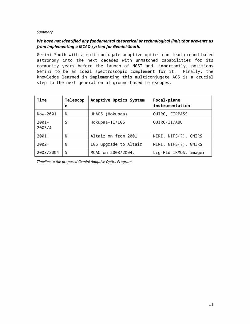
Gemini-South with a multiconjugate adaptive optics can lead ground-based astronomy into the next decades with unmatched capabilities for its community years before the launch of NGST and, importantly, positions Gemini to be an ideal spectroscopic complement for it. Finally, the knowledge learned in implementing this multiconjugate AOS is a crucial step to the next generation of ground-based telescopes.
Time Telescope Adaptive Optics System Focal-plane instrumentation
Now–2001 N UHAOS (Hokupaa) QUIRC, CIRPASS
2001-2003/4 S Hokupaa-II/LGS QUIRC-II/ABU
2001+ N Altair on from 2001 NIRI, NIFS(?), GNIRS
2002+ N LGS upgrade to Altair NIRI, NIFS(?), GNIRS
2003/2004 S MCAO on 2003/2004. Lrg-Fld IRMOS, imager
Timeline to the proposed Gemini Adaptive Optics Program
8
9
1 IntroductionIn this section, we briefly describe what MCAO is and the gains brought by it, and put this proposed AO program into a more general context.
1.1 What is MCAO ?
The limiting magnitude of the usable guide star and the limited isoplanatic patch are the two fundamental limitations of adaptive optics. The use of Laser Guide Stars (LGS) relieves the first one, but a LGS AO system still has a limited field of view (FoV), and suffer from PSF variations across the field, which makes the data reduction a difficult job to carry out for moderate fields (10-30’’).
This limitation, together with the cone effect associated to the use of LGSs is solved by the use of Multi-Conjugate Adaptive Optics (MCAO).
The principles of MCAO are described in some details in section 3. The basic idea is to compensate for the turbulence in a 3-dimensional fashion, by having several deformable mirrors conjugated to different altitude, instead of the single deformable mirror, usually conjugated to ground level, of classical/existing AO systems. By using this technique, MCAO is able to reach on-axis NGS AO type performance, with a uniform PSF, over 1-2+ arcmins field of view. The basic advantages of an MCAO system with respect to more conventional NGS or LGS systems are:
Increased sky coverage (approximately 50%) w/ respect to a NGS system (50-500x)
Increased performance on axis w/ respect to a LGS system because the cone effect is taken care of
Increased field of view Uniform PSF across the field of view, which renders the
data reduction much easier, accurate and stableThese advantages are illustrated in figure 1.1 and 1.2, which show a performance example of a medium order MCAO.
The proposed instrument will basically offer diffraction limited performance from one micron and longward, with Strehl ratio in median seeing conditions in the range of 50-65% (J band, AO contribution only) and 80-90% (K band, AO only). Corresponding slit coupling efficiencies, e.g. for a 0.1 arcsec slit, are 60-70% in J band to 80% in K band (see section 2).
10
Figure 1.1: An example of NGS MCAO capability. Simulated stellar field with 320 stars, showed without AO, with a classical single guide star/deformable mirror AO and with a 2 deformable mirror/5 guide star MCAO. The wavefront sensors have 8x8 subapertures. The field of view is 165 arcsec, the wavelength is 2.1 micron. The telescope aperture is 8-m. The natural seeing is 0.7 arcsec at 550 nm. Note that each star has been blown up by 15x to be able to better see the PSF variations. Because of this, the crowding looks worse than it actually is (especially on the No-AO image). The guide stars are not shown on these images, but their positions are marked by crosses.
Title:Graphics produced by IDLCreator:IDL Version 5.2 (sunos sparc)Preview:This EPS picture was not savedwith a preview included in it.Comment:This EPS picture will print to aPostScript printer, but not toother types of printers.
It is worthwhile to note that the proposed system can be build with the currently existing/available technology. An exception to that is the laser (4-5 Altair type lasers), but such laser will have to exist for Altair in a 3 years horizon (we are putting out an RFP in 10/99), and we are confident that these can be scaled up or multiplexed (more argumentation on that in section 4). The complexity of building this instrument mostly lies into its optomechanical packaging. This feasibility study presents a very encouraging “proof-of-existence” optomechanical design in section 4. Another issue, that we have addressed, is the computing power. Although large, the computing power requirements are of the same order or lower than currently existing very high order AO systems (AF at SOR).
The conclusion of the present study is that we have not identified any show stoppers, either theoretical or technological.
1.2 Cerro Pachon AOS/LGS forumA Forum on the Gemini South Facility was organized in April 1999 in Hilo. AO and science from the Gemini community and beyond were invited to participate and present their thoughts/proposal for the CP AO facility. The response was overwhelming, with around 40 participants. One of the trends of this forum was that a significant number of attendants were interested in participating in the subsystem design/fabrication, but no group stepped ahead to take charge of the whole system. As a result of this forum, a recommendation on how to proceed for the CP AO facility was put together by a review panel. The current feasibility study derives directly from the review panel recommendation.
Cerro Pachon LGS/AOS Forum, 19/20 April 1999, HILO
Recommendations to the Director of the IGPO from the review panelReview Panel members: Mark Chun (IGPO), Roberto Ragazonni (Padova Observatory), Francois Rigaut (IGPO-Chair), Chris Shelton (Keck), Doug Simons (IGPO), and Peter Wizinowich (Keck)
1. The IGPO should develop a strategy for its overall adaptive optics program which satisfies the Gemini community. Timing of the program, staff resources, and cost must be addressed. The RP also notes that the experience gained with the Altair AO and Hokupa'a teams are valuable to the overall program and should be folded into the planning.
2. The Project should conduct a significant but time-limited study of a multiconjugate adaptive optics system for Cerro Pachon. This would provide an exciting advancement in capabilities but implementing the system should be conditional on "filling" the AO gap on Gemini-South and addressing the requirements of the coronagraphic imager. The study should address the theoretical
11
Title:Graphics produced by IDLCreator:IDL Version 5.2 (sunos sparc)Preview:This EPS picture was not savedwith a preview included in it.Comment:This EPS picture will print to aPostScript printer, but not toother types of printers.
Figure 1.2: Strehl ratio versus field angle for a classical pupil-conjugated AO system (triangles) and a MCAO system (crosses), from the star field shown in Figure 1.1. Note the Strehl ratio plateau, and the smooth decrease compared to the classical AO case. Note that these results have been obtained with a MK turbulence profile, and are therefore mostly illustrative and not directly applicable to CP.

analysis, science drivers, technical challenges, systems engineering, and programmatic of such an AO system. With the development of a plan, the RP recommends that Gemini adopt as aggressive a schedule as possible to bring this capability to the community.
3. The IGPO should lead the conceptual design program of the Gemini-South AO system, including defining the allocation of subsystems across the Gemini Community.
4. In light of the proposals presented for turn-key laser systems, the RP recommends that the IGPO explore with LiteCycles the manufacture of a Sum Frequency laser. To reduce cost and risk for the laser, procurement through a consortium should be explored, including Keck, and possibly other groups if they can participate on time scales which are consistent with Gemini's schedule for laser deployment.
5. The project should avoid relying on major technological developments such as MEMs, liquid crystals, and other 'advanced' DMs for the CP AOS.
1.3 Context / Gemini CompetitivenessGround-based astronomy is currently undergoing a tremendous change in the collecting area and angular resolution available throughout the world. The collecting area of the entire community will more than triple as the current suite of large 8-10m class telescopes become available. Already, we have seen the resolving power of these telescopes increase by a factor of 10 with the use of adaptive optics systems. However, these systems –NGS or LGS- are still limited in field of view, which limits the science applications. The typical corrected field of view1 in J band for a high-order AO system like Keck II is about 20’’ in radius.
1 Here the corrected field-of-view is defined as the field angle at which the Strehl drops by a factor of 2 due to angular anisoplanatism.
12
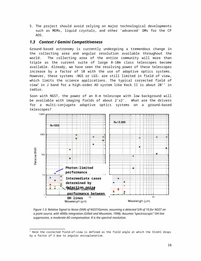
Figure 1.3: Relative Signal to Noise (SNR) of NGST/Gemini, assuming a detected S/N of 10 for NGST on a point source, with 4000s integration (Gillett and Mountain, 1998). Assumes “spectroscopic” OH line suppression, a moderate AO compensation. R is the spectral resolution.
Photon-limited performance between OH lines
Photon-limited performance averaging OH lines
Intermediate cases determined by detection noise
Soon with NGST, the power of an 8-m telescope with low background will be available with imaging fields of about 2’x2’. What are the drivers for a multi-conjugate adaptive optics systems on a ground-based telescopes?
MCAO enables NGST-type science 5 years prior to the NGST launch.
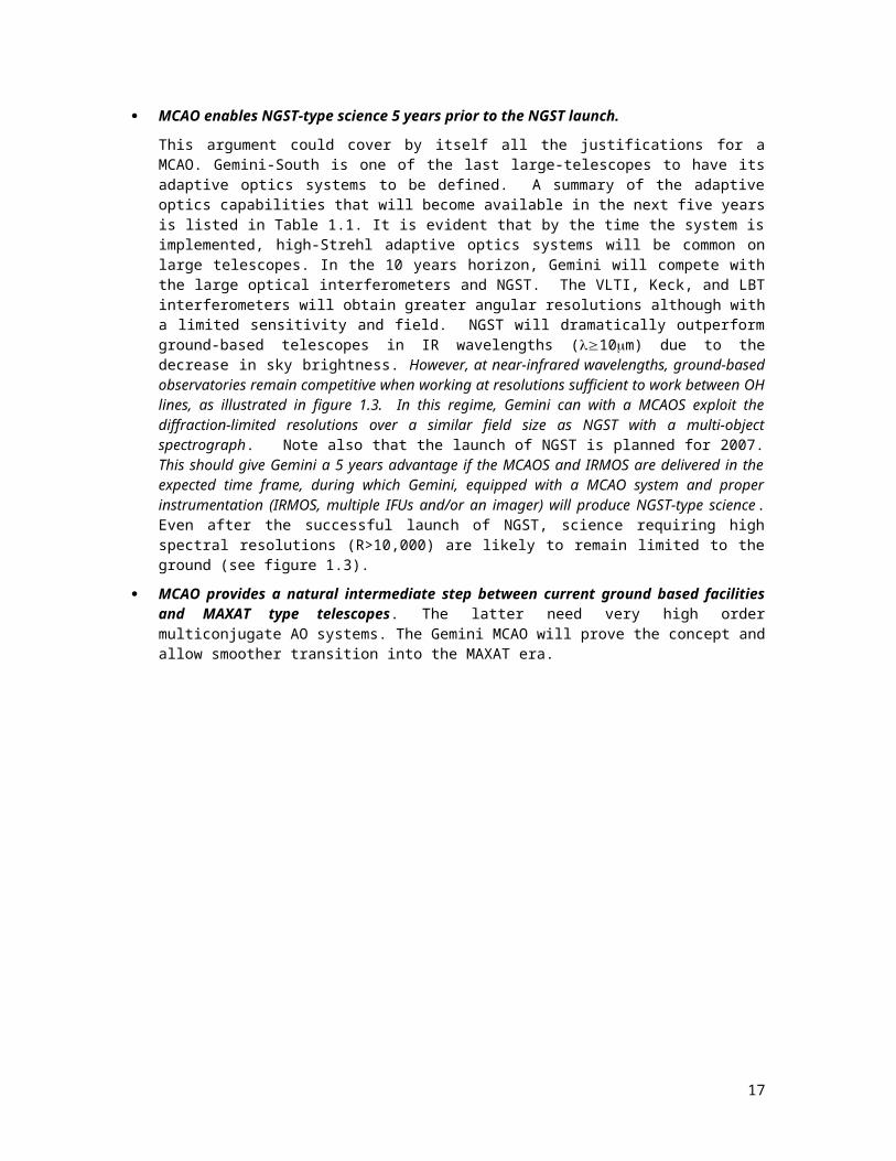
This argument could cover by itself all the justifications for a MCAO. Gemini-South is one of the last large-telescopes to have its adaptive optics systems to be defined. A summary of the adaptive optics capabilities that will become available in the next five years is listed in Table 1.1. It is evident that by the time the system is implemented, high-Strehl adaptive optics systems will be common on large telescopes. In the 10 years horizon, Gemini will compete with the large optical interferometers and NGST. The VLTI, Keck, and LBT interferometers will obtain greater angular resolutions although with a limited sensitivity and field. NGST will dramatically outperform ground-based telescopes in IR wavelengths (10m) due to the decrease in sky brightness. However, at near-infrared wavelengths, ground-based observatories remain competitive when working at resolutions sufficient to work between OH lines, as illustrated in figure 1.3. In this regime, Gemini can with a MCAOS exploit the diffraction-limited resolutions over a similar field size as NGST with a multi-object spectrograph . Note also that the launch of NGST is planned for 2007. This should give Gemini a 5 years advantage if the MCAOS and IRMOS are delivered in the expected time frame, during which Gemini, equipped with a MCAO system and proper instrumentation (IRMOS, multiple IFUs and/or an imager) will produce NGST-type science. Even after the successful launch of NGST, science requiring high spectral resolutions (R>10,000) are likely to remain limited to the ground (see figure 1.3).
MCAO provides a natural intermediate step between current ground based facilities and MAXAT type telescopes. The latter need very high order multiconjugate AO systems. The Gemini MCAO will prove the concept and allow smoother transition into the MAXAT era.
13
Facility AOS Schedule (tentative)
SR2.2m Limiting Magnitude
2.2 m Sky Cov.2
Focal-plane Instruments (Schedule)
Keck-II Keck II AO Facility
NGS: Now
LGS: 2000
0.8 NGS: 13
LGS: 18
0.4%
19%
NIRC2 (Now)(10242 InSb)
NIRSPEC (Now)(10242 InSb, R-2000-25000)
Gemini-N Hokupaa 36-element CS
NGS: Now 0.3 NGS: 16 2% QUIRC (Now)(10242 InSb)
Subaru 37-element CS NGS: 2000? 0.3 NGS: 16 2% CIAO (?)(Coronographic Imager)
IRCS (?)(Spectrograph)
MMT adaptive M2 NGS: 2000
LGS:?
0.7 NGS:~13
LGS:17-18
0.4%
19%
?
VLT NAOS NGS: 2001
LGS: 2003?
0.7 NGS: ~13 0.4% CONICA (1999)(10242 InSb)
Gemini-N Altair NGS: 2001
LGS: 2002
0.65 NGS: 13
LGS: 18
1.5%
19%
NIRI (2000)
GNIRS (2002/3)
VLT MACAO 36-element CS
NGS: 2002 0.3 NGS: 16 2% SINFONI (2001) (IFU spectrograph)
LBT adaptive M2? 2002-2003 ? ? ? ?
Gemini-S MCAO End of 2003 0.8 LGS: 18/20 50% IRMOS (2003)
Deployable IFUs (?)
Table 1.1: Summary of Adaptive Optics Facilities on 8-10 m Telescopes
2 Sky coverage is the percentage of the sky in which one would achieve ‘high’ performance from the AOS. They use the galactic models of Bahcall and Soneira (1984) for the North Galactic Pole. The guide star-science target separation is taken to be 30’’ in the NGS case and 60’’ in the LGS case. Note that in the case of Altair-NGS the allowable separation was increased by a factor of 2 (diameter) to account for the conjugation to altitude
14
2 Science Drivers
2.1 General ConsiderationsA variety of science cases were considered in the document justifying the construction of Altair for Gemini (Morris et al. 1996). These science cases were revisited in the Altair Operational Concepts Definition Document (Morris, Herriot and Davidge 1997), where 5 cases were considered in more detail. In parallel with this effort, a meeting was held at Abingdon in January 1997 where the science drivers for the Gemini On-Going Instrumentation Plan (OGIP) were formulated (Gillett et al. 1997).
In none of these Gemini documents was the possibility of wide FOV AO considered. However, it is certainly clear that many of the science cases considered would benefit substantially from MCAO. From the list in Table 1 of the Altair OCDD, clear cases of this are:
Studies of star formation - star formation regions are complex and inter-related. It is naïve to assume that a star forming region can be studied in isolation, without complementary information about the surrounding regions.
Local Group Old Stars - studies of the stellar populations in the bulge and disk of M31 require AO to resolve stars in crowded fields, and the MCAO will allow reasonable samples of stars to be observed in a single exposure.
Starburst galaxies - many of the nearer starburst galaxies subtend more than an arcminute, while individual giant HII regions in these objects are < 1 arcsecond in diameter. Spatially resolved spectroscopy across the extent of these galaxies will allow us to understand the triggering and propagation of the star formation. (It should be noted that the above arguments also apply for galaxies not currently undergoing starbursts - where one might wish to still study the star formation process).
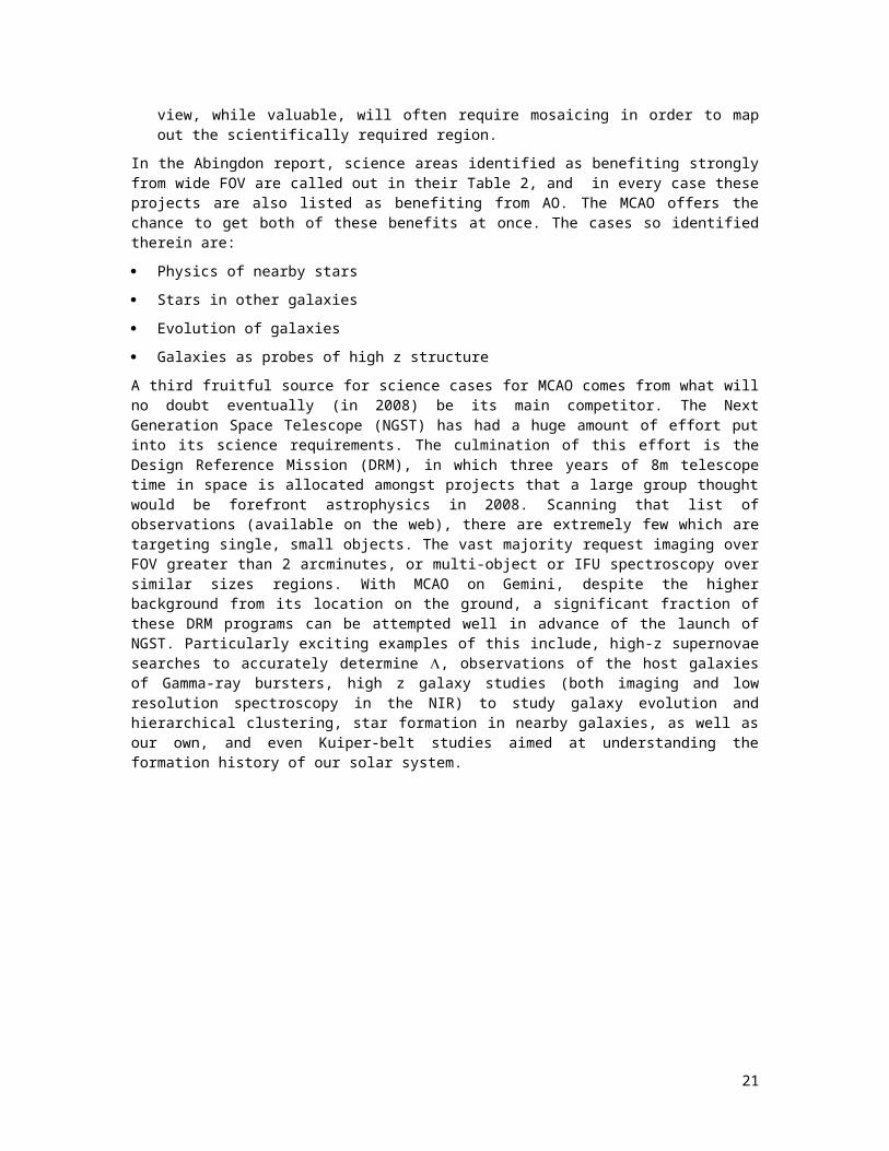
Gravitational arcs - while individual giant arcs are generally only a few arcseconds along their long dimension, and entire set of images for a given background galaxy may well be spread over an arcminute or more. Spatially resolved spectroscopy of all of these images will allow detailed reconstruction of the high redshift lensed galaxy, with information on scales that will be unobservable in any other way.
High redshift galaxies and clusters - we will explore this case in more detail below, but the cores of moderate redshift clusters of galaxies subtend a few arcminutes, while the comoving volume from which objects such as the local group were likely assembled also subtends this sort of scale at high redshifts. Smaller fields of view, while valuable, will often require mosaicing in order to map out the scientifically required region.
In the Abingdon report, science areas identified as benefiting strongly from wide FOV are called out in their Table 2, and in every case these projects are also listed as benefiting from AO. The MCAO offers the chance to get both of these benefits at once. The cases so identified therein are:
Physics of nearby stars
Stars in other galaxies
Evolution of galaxies
Galaxies as probes of high z structure
A third fruitful source for science cases for MCAO comes from what will no doubt eventually (in 2008) be its main competitor. The Next Generation Space Telescope (NGST) has had a huge amount of effort put into its science requirements. The culmination of this effort is the Design Reference Mission (DRM), in which three years of 8m telescope time in space is allocated amongst projects that a large group thought would be forefront astrophysics in 2008. Scanning that list of observations (available on the web), there are extremely few which are targeting single, small objects. The vast majority request imaging over FOV greater than 2 arcminutes, or multi-object or IFU spectroscopy over similar sizes regions. With MCAO on Gemini, despite the higher background from its location on the ground, a significant fraction of these DRM
15
programs can be attempted well in advance of the launch of NGST. Particularly exciting examples of this include, high-z supernovae searches to accurately determine , observations of the host galaxies of Gamma-ray bursters, high z galaxy studies (both imaging and low resolution spectroscopy in the NIR) to study galaxy evolution and hierarchical clustering, star formation in nearby galaxies, as well as our own, and even Kuiper-belt studies aimed at understanding the formation history of our solar system.
Figure 2.1: Multiple images of a background ring galaxy can be seen. This cluster does not have a suitable star for NGS AO, and the images above are spread over a large enough region to require MCAO.
2.1.1 A Few Specific ExamplesBelow we give a few illustrative examples of how studies of galaxy formation and evolution benefit from MCAO. MCAO science applications are obviously not restricted to extra-galactic work. YSOs in general, and even planetary astronomy will find great support from MCAO.
2.1.1.1 Evolution of StructureThe redshift evolution of galaxy clustering is a fundamental test of all theories for the origin of structure in the Universe. There are now a large number of very sophisticated statistical measures for the amount and form of clustering amongst the galaxy population. The simplest of these are the two-point correlation function and the spatial power spectrum. For either of these statistics, samples of a few hundred galaxies along a given redshift column from zero to perhaps as high as 10 will be extremely inadequate.
16
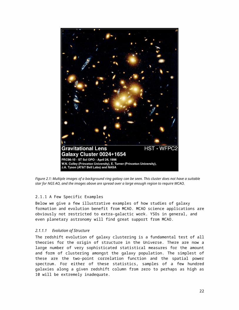
To illustrate this point graphically, the figure 2.2 shows a pie diagram from the recently completed CNOC2 survey (Carlberg et al. 1999). The y-axis has been greatly expanded to allow one to see the individual points, but nevertheless one can see that with 1500 galaxies and a redshift column from 0.1 to 0.7 one can begin to see a wealth of structure. Removing a large fraction of these points and then spreading the remainder over an enormously expanded redshift range will make clustering studies impossible. Formal error estimates for the two-point correlation function as a function of number of objects and redshift scale as the square root of the number of galaxies in each redshift bin, and so very large samples are needed.
The need for large samples is made more extreme by the clear desire to break up any galaxy sample still further to look for clustering as a function of galaxy properties such as luminosity, colour, star formation rate, or morphology (see Kauffmann et al. 1998). In justifying the request for a sample of 2500 galaxies in order to study evolution in their properties with R=1000 spectroscopy, the NGST DRM for example proposes breaking the sample into 5 redshift bins, 6 mass bins and 4 star formation rate bins, yielding 20 galaxies per bin.
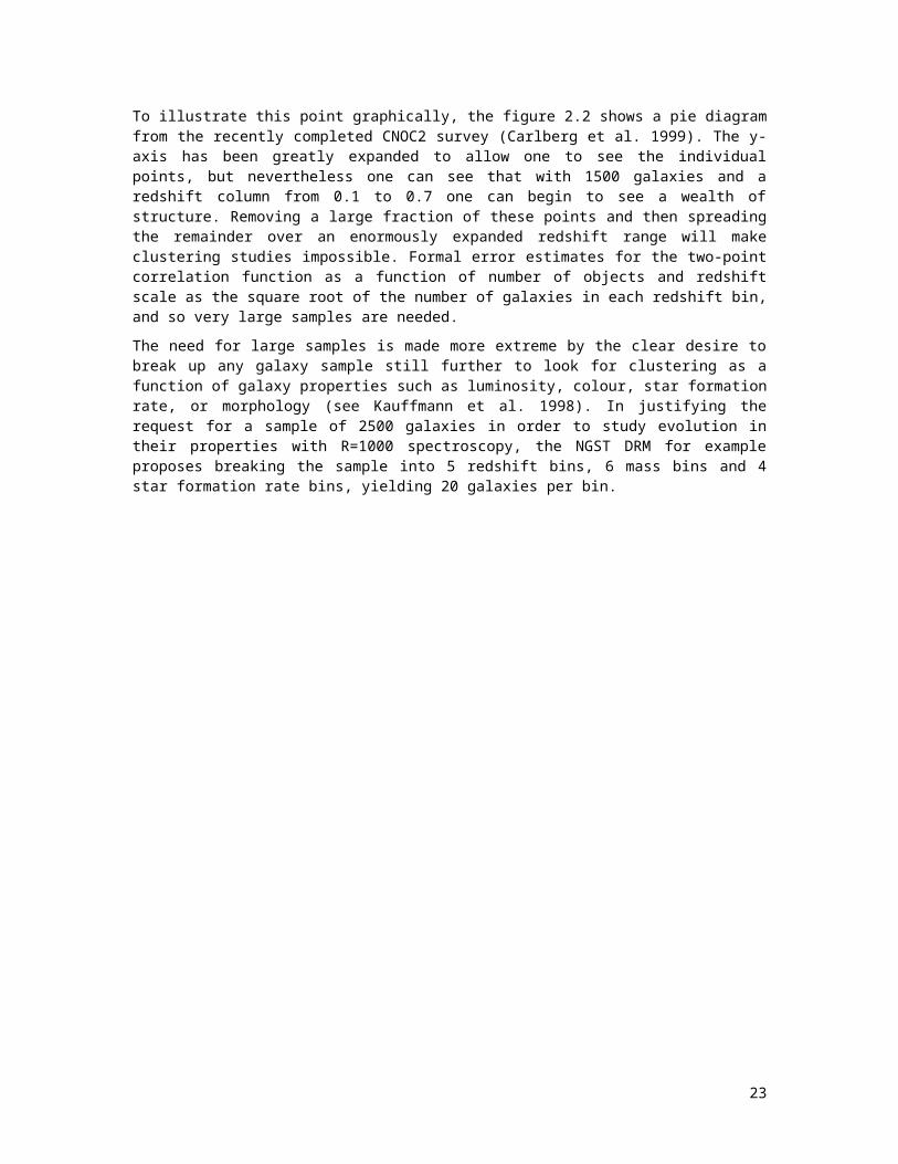
Figure 2.2: Pie diagram showing ~1500 galaxies in a 2 degree region of the sky surveyed as part of the CNOC2 survey (Carlberg et al. 1999). The x-axis labels are redshift. The tick marks on the y-axis show 1/h proper Mpc.
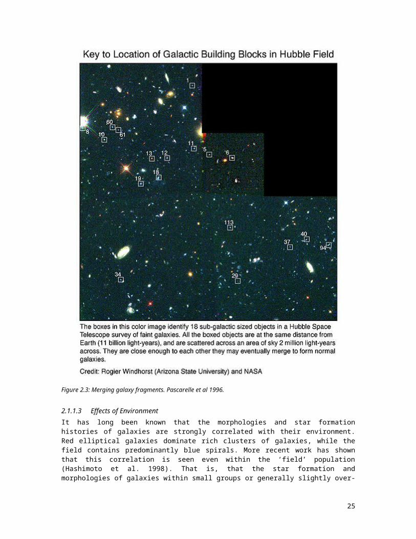
2.1.1.2 Location of Merging FragmentsThe figure 2.3 shows the results from an HST study by Pascarelle et al (1996). They used a 0.15 micron wide filter to identify objects with Lyman- emission at z=2.39 associated with a weak radio galaxy. The figure shows 18 candidate ‘fragments’ spread across a 2.5 arcminute field (corresponding to 0.7 Mpc for h=0.8, q0=0.5). At least 8 of these fragments have been confirmed spectroscopically, and have been shown to have a relatively small velocity dispersion (~300 km/s). It has therefore been claimed that these fragments will have merged to form an early type galaxy by the present day.
17
It is clear from Figure 2.3 that identifying all such fragments will be extremely arduous without MCAO. After identifying the candidate fragments using photometric redshifts, one would then like to follow up a subset of these fragments at higher spectral resolution in order to measure their velocity dispersion.
Figure 2.3: Merging galaxy fragments. Pascarelle et al 1996.
2.1.1.3 Effects of EnvironmentIt has long been known that the morphologies and star formation histories of galaxies are strongly correlated with their environment. Red elliptical galaxies dominate rich clusters of galaxies, while the field contains predominantly blue spirals. More recent work has shown that this correlation is seen even within the ‘field’ population (Hashimoto et al. 1998). That is, that the star formation and morphologies of galaxies within small groups or generally slightly over-dense regions is also significantly different from that of galaxies in low density regions. The Hashimoto et al. Study used the LCRS sample of 15,000 galaxies
18

spread over a large angle on the sky, but limited to redshifts less than 0.2. Turning again the Pie diagram above, it is clear that samples of 100-500 galaxies would not be sufficient to measure the local galaxy density. Again the wide field of MCAO will be needed for efficient observation.
2.1.1.4 Additional Benefits of Large Samples to the GDRMThree rather general points can be made about the benefits of large samples of objects with relatively complete spectroscopic information:
1. Such samples make possible the finding of rare and unusual objects. Some possible examples of such objects would be very high redshift galaxies, Ultra-Luminous Infra-Red Galaxies, or low-luminosity, low star-formation rate dwarfs.
2. Another general area needing large samples is anything where one would like to break the galaxy sample into several bins. Immediately obvious cases of this are studies of the star formation rate as a function of redshift, or the evolution in galaxy metallicity with redshift. For both of these one would like to break the galaxy sample into several bins in luminosity, morphological class, and possibly also spectral class. This division (on top of binning in redshift) will rapidly reduce a sample of a few hundred galaxies to statistical meaninglessness.
3. Selection effects often plague studies of galaxy evolution. Substantial samples are needed to quantify and correct for any such effects.
It is also true the high spatial resolution wide FOV data will undoubtedly prove to be a rich source for serendipitous discoveries.
2.1.1.5 Star formation in galaxies at z~1-3Over the last several years great strides have been made in finding galaxies at very high redshifts and estimating the star formation history of the universe (cf. Steidel et al. 1996, Madau et al. 1996). The emerging picture of the history of star formation in galaxies in the universe suggests that the star formation rate was higher in the past than measured locally; the star formation rate has decreased for redshifts less than z ~ 2 by a factor of about 10. Beyond a redshift of z~2, dust, AGN contributions, and use of different diagnostics make the picture more difficult to interpret. However, a deviation from an increasing star formation rate with redshift occurs around z~1 to z~3. The gap in observations at this redshift is due to the shift of the key optical diagnostics lines into the near infrared. For example, the relatively direct measure of the current star formation rate using the hydrogen recombination line H, becomes difficult with optical at around z~0.5-1. Use of optical diagnostic lines such as H, H, and [OIII]5007 are important since they are less extinct by dust, the major unknown in estimations of the star formation rate using the UV continuum. Note that the use of [OIII] used in conjunction with the hydrogen recombination lines also gives a handle on the metallicity in these systems.
With a multi-conjugate adaptive optics system with good performance throughout the near-infrared and a multi-object spectrograph, Gemini will be able to explore this redshift range with a great multiplexing advantage. An angular resolution sufficient to resolve emission originating from the core and from discrete HII regions in the outer portions of the galaxies is obtained for resolutions of ~0.1''. (The minimum angle subtended by a 1 kpc region due to the curvature of space is 0.2'' (for H 0=75 km/s/Mpc and q0=0.5).) Assuming a conversion factor of 1041erg/s per M/yr in star formation (Kennicut 1983), we find that on Gemini, H can be observed (5, 3600sec) out to redshifts z~2.5 for galaxies with a total star formation rate greater than 1 M/year. As the galaxy will be resolved, this corresponds to detection of the typically brightest HII regions in galaxies out to z~2.5 (assuming no evolution). In order to study field and cluster galaxies in a systematic way, we need the multiplexing capability of multi-object spectroscopy. If we assume that the density of galaxies is the same as locally, then there should be ~2-10 L* galaxies per square arcmin within the redshift range 1<z<3 (Thompson et al. 1994). For an MCAO with a 2' x 2' field of view, this requires 8-40 discrete slits or deployable-IFUs in the MOS.
19

2.1.1.6 Search for high redshift galaxiesRich clusters at redshifts of 0.4-0.7 show strong gravitational lensing of the background objects. The gravitational lensing makes the lensed objects appear brighter than they would have without the lensing. This makes rich clusters an optimal place to search for very high redshift objects - behind the clusters. We are effectively using the rich cluster as an addition to the telescope.
Many of the lensed objects have very small angular sizes; often less than one arcsecond. Thus, in order to study the lensed objects in any detail superior spatial resolution is needed. There are examples of cases where reconstruction of real spatial appearance has been attempted based on HST/WFPC2 data. The lensed objects found with optical data often have redshifts less than 1-1.5. However a few very high redshift objects have been found.
The typical spectral energy distribution of galaxies (especially those that are dominated by old stellar populations) makes it very hard to detect galaxies with redshifts from about 1.3 to 3.2 using optical data. [At redshift 1.3 the 4000A break is redshifted to far into the red to be observable with optical observations. At redshifts larger than 3.2 the Ly-alpha line becomes observable in the optical.] As a result very little is know about stellar populations in galaxies with redshifts in this interval. Detecting these galaxies should be possible using the near IR - and searching for them as lensed objects behind rich intermediate redshift clusters should make the task easier.
The candidate high redshift galaxies may identify in two ways: (1) redshift 2.3-4.0 based on the 4000 A break and drop-outs in J and/or H, and (2) redshifts from 1 to 4 based on the near-IR colors. We may also have the possibility of detecting galaxies at even higher redshifts based on the drop-out method. There are breaks in the UV that at very high redshifts will be observable in the near-IR.
A large field, e.g. 2’x2’, is very important for the success of such a search. With 2'x2' we can carry out the search for high redshift galaxies behind the core of a cluster at redshift around 0.5 with one field observed. Since these high redshift galaxies may be very difficult to find it is essential to have a large field of view.
Once candidate high redshift galaxies are found, follow-up spectroscopy may be possible for the brightest candidates. The spectroscopy will also benefit greatly from the AO. In fact, such observations are most likely impossible without AO due to the small angular size of the lensed galaxies combined with the bright background in the near-IR.
2.1.1.7 Ages, metal content and structure of distant dwarf galaxiesThe origin and destination of the dwarf galaxies in rich clusters can give us information about the evolutionary processes of the clusters as a whole. There are theories that predict the dwarf galaxies are “failed” galaxies - they never got big enough. Other theories predict that dwarf galaxies are formed by pieces of larger galaxies that got separated during mergers and interactions. These two possible sources of the formation of dwarf galaxies result in very different properties of the stellar populations in terms of ages and metal content. If dwarf galaxies are formed from pieces of larger galaxies, they may have a larger metal content and may also have a different mean age than if they are “failed” galaxies formed on their own from smaller density enhancements.
Very little is known about how the population of dwarf galaxies evolve over time since is it difficult to observe these faint galaxies at redshifts large enough (z up to about one) to address this problem. Further, even when imaging in the optical is done we cannot distinguish metal variations from age variations for the old stellar population in these galaxies. By "old stellar populations" is meant ages larger than about 2-3 Gyr, e.g. no emission lines.
Imaging in the near-IR with AO will give sufficient resolution to study the scale lengths and surface brightness of dwarf galaxies in intermediate redshift clusters (z ~ 0.2-1.0). This will give the possibility of addressing the evolution of the structure of this population of galaxies. Further, by combining the near-IR observations with observations in the optical (e.g. HST/WFPC2) we can break the degeneracy of age and metal content. This may make it possible to study how the stellar populations in these galaxies evolve over time and test the models for their evolution in detail.
In order to cover large enough samples of galaxies in an efficient way a field of view that covers the cores of intermediate redshift clusters is needed. A field of view of 2'x2' will do just that. Further, it is a
20
requirement that there are no large PSF variations over the field, since otherwise surface photometry of the galaxies will become very difficult to obtain.
2.2 Science RequirementsThis section expresses our current thinking on the subject. Discussion is expected and encouraged.
A useful source/baseline is the science specifications document for Altair.
Science requirements for the MCAO should encompass both spectroscopic and imaging applications, to cover the broadest range of science. In view of the NGST-type science program, oriented toward moderate field of view, some common specifications emerge:
Angular resolution:
Imaging of bright sources: diffraction limited in J, H and K
Imaging and spectroscopy of faint sources: Resolution is probably not the very limiting factor, not as much as Strehl, for SNR reasons (IRMOS will most probably be undersample to increase sensitivity)
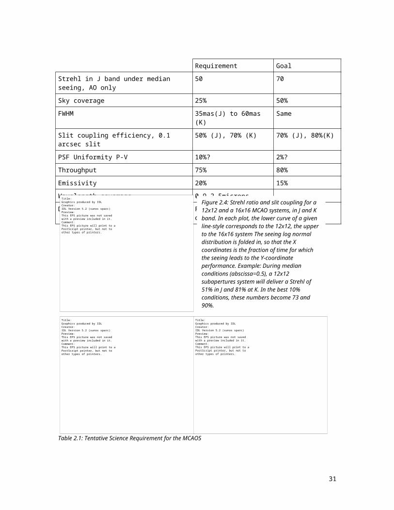
Strehl ratio: Should be maximized for both imaging and spectroscopy. Strehl ratio drives directly the SNR for resolved objects, both in imaging and spectroscopy. More exactly, it is encircled energy/slit coupling efficiency that is the relevant parameter for spectroscopy, but these parameters are directly related to the Strehl ratio. Figure 2.4 gives the Strehl ratio and the slit coupling efficiency for a “low-end” (12x12 subapertures) and a “high-end” (16x16 subapertures) MCAO systems. Because the guide star magnitude is not anymore a major driver of the performance (LGSs have more or less constant brightness) and that field anisoplanatism is not relevant anymore, the main parameter to determine the system performance is the seeing. By folding in the seeing statistics, one can therefore predict the distribution of Strehl ratio or other relevant metrics. These curves should be useful to specify the order of the MCAO system, especially considering the queue operation mode adopted at Gemini.
Field of view: This is mostly driven by existing hardware (field stop and mirrors) in the telescope, and is limited to 2 arcmin.
Uniformity of the PSF: This would have to be addressed/simulated. It is difficult to say up front how much the PSF is allowed to fluctuate across the field. There is nevertheless two kinds of fluctuations: The absolute fluctuations, may be due to system design/trade off, and the residual fluctuations after calibration. Although the latter are certainly the most damaging, the first ones (absolute fluctuations) are to be avoided as well, as it will re-introduce some kind of PSF variation and therefore make data reduction processes more complex. It is our opinion that the gain brought by PSF uniformity is absolutely crucial. The past has shown that these fluctuations are difficult to deal with when relatively high accuracy is searched. MCAO should solve this problem, and should be required to do so.
A tentative requirement list is presented in table 2.1.
21
Requirement Goal
Strehl in J band under median seeing, AO only 50 70
Sky coverage 25% 50%
FWHM 35mas(J) to 60mas (K) Same
Slit coupling efficiency, 0.1 arcsec slit 50% (J), 70% (K) 70% (J), 80%(K)
PSF Uniformity P-V 10%? 2%?
Throughput 75% 80%
Emissivity 20% 15%
Wavelength coverage 0.9-2.5microns
Dithering Frequency and offsets?
Table 2.1: Tentative Science Requirement for the MCAOS
22
Title:Graphics produced by IDLCreator:IDL Version 5.2 (sunos sparc)Preview:This EPS picture was not savedwith a preview included in it.Comment:This EPS picture will print to aPostScript printer, but not toother types of printers.
Title:Graphics produced by IDLCreator:IDL Version 5.2 (sunos sparc)Preview:This EPS picture was not savedwith a preview included in it.Comment:This EPS picture will print to aPostScript printer, but not toother types of printers.
Title:Graphics produced by IDLCreator:IDL Version 5.2 (sunos sparc)Preview:This EPS picture was not savedwith a preview included in it.Comment:This EPS picture will print to aPostScript printer, but not toother types of printers.
Figure 2.4: Strehl ratio and slit coupling for a 12x12 and a 16x16 MCAO systems, in J and K band. In each plot, the lower curve of a given line-style corresponds to the 12x12, the upper to the 16x16 system The seeing log normal distribution is folded in, so that the X coordinates is the fraction of time for which the seeing leads to the Y-coordinate performance. Example: During median conditions (abscissa=0.5), a 12x12 subapertures system will deliver a Strehl of 51% in J and 81% at K. In the best 10% conditions, these numbers become 73 and 90%.
3 Performance and Optimization of the MCAO System
3.1 Adaptive Optics Primer
3.1.1 Limiting magnitude and sky coverageThe primary limitation of AO systems using natural guide stars (NGSs) is the sky coverage. Because the phase aberrations have to be measured over a finite spatial scale (r 0()) and time scale (0()), and with a useful SNR, only stars brighter than a given limiting magnitude can be used. For typical seeing conditions and a compensation in the near IR, typical limiting magnitudes are mR=13-15. This, coupled with the fact that the compensation is valid only in a limited angular area (more on the isoplanatic patch below), limits the sky coverage, i.e. the area of the sky in which a suitable level of compensation can be achieved. Typical values for sky coverage, for adequate compensation in the near IR, are of the order of 0.1 to 1%.
3.1.2 Isoplanatic patchBecause the turbulence is vertically distributed over several kilometers, and not all located in a single layer at the ground, the phase corrugation is not isotropic, or isoplanatic. This means that it changes according to the direction in which the telescope is pointing. Practically, for typical vertical distributions of turbulence and typical seeing, the phase angular decorrelation is such that the isoplanatic patch (defined here as the radius of the field over which the Strehl loss is lower or equal to 50%) is typically equal to 40’’ in K band. This angle scales as 1.2, which then translates into 25’’ at H band and 20’’ at J band.
Summary: The major fundamental limitation of NGS AO systems is sky coverage, which results from a combination of the finite limiting magnitude and isoplanatic patch. Typical values of sky coverage, for adequate compensation in the near IR, are of the order of 0.1 to 1%.
3.1.3 Laser guide stars and cone effectBecause the sky coverage is so low with NGSs, the use of Laser Guide Stars (LGSs) was proposed in 1985 (Foy and Labeyrie). The idea is to create an artificial beacon, or artificial star, by resonant scattering of the Sodium atoms located in the 10km thick, 90km high Sodium layer. Projected from an auxiliary telescope mounted on the observing telescope (or not), this beacon can be created wherever it is needed, and in particular where no NGS is available. Unfortunately, this LGS do not provide a full solution. Indeed, two fundamental problems are associated with the use of LGS’s (in addition of all the FAA regulations about shooting up several watts of yellow colored laser): The cone effect and the tip-tilt problem.
3.1.3.1 Cone effectBecause an LGS is at finite altitude (90km), the beam propagating back to the telescope aperture does not follow the same path as the beam from a celestial object, located at infinity. Therefore, there is an estimation error, which results in a phase error, and in a degradation of the performance. This effect has been recognized early and quantified by several authors (Foy and Labeyrie 1985, and e.g. Parenti and Sasiela 1994). Its amplitude depends on the vertical profile of turbulence and on D/r 0 in the telescope aperture, which means that it becomes more critical toward shorter wavelengths, for larger telescope apertures, or for worse seeing. In a regular astronomical site and for an 8-m telescope, the Strehl ratio attenuation due to the cone effect is typically 50% at about 1.25m, and reduces the performance further to almost zero at visible wavelengths.
3.1.3.2 Tip-tilt problemA LGS is not fixed in the sky. Indeed the laser is shot from ground level, and before it hits the sodium layer and is back scattered, it crosses some turbulence. This induces a wander of the spot at 90km, which in turn make its position unpredictable (in the deterministic sense). The LGS still provides useful information from one part of the pupil to the next (relative phase excursion across the telescope aperture), but the overall tilt cannot be unequivocally extracted from the LGS information. In addition to the LGS, one therefore needs a
23
NGS that will provide the tip-tilt–image motion-information (TTNGS). Because the whole telescope aperture is used in TT sensors, a NGS significantly fainter than the one required for NGS-only systems can be used. Typical limiting magnitude for TTNGS are mR=18. Such systems lead to approximately 30-50% sky coverage in the near IR, which is a major improvement with respect to NGS systems.
Summary: Compared to NGS AO, LGS AO significantly improves the sky coverage, but the cone effect reduces their performance-Strehl ratio- by about 50% at 1 micron (and more at shorter wavelengths). Sky coverage is still limited by the need for a tip/tilt natural guide star.
3.2 Multi-Conjugate Adaptive OpticsTo solve this problem, several schemes have been proposed, that use several LGS in order to probe the entire volume of turbulence crossed by the light propagating from an object at infinity. The measurements from the various LGSs have then to be processed/mixed to extract the relevant information. Independently, Beckers (1988) proposed to use several deformable mirrors to compensate for the off-axis degradation of the image quality in an AO system, due to the anisoplanatism of the phase corrugation (given that in all AO system up to date, there is only one deformable mirror, usually conjugated to the ground, to compensate for the phase distortions). No convincing control scheme were found to beat the cone effect until Ellerbroek (1994), Fusco et al (1999), and Rigaut et al (1999) proposed to associate turbulence tomography-using several LGS and wavefront sensors-with multiconjugate DM’s, and to consider both measurements and mirrors in a global estimation problem, without explicitly trying to reconstruct the 3-dimensional phase.
This scheme is called Multi-Conjugate Adaptive Optics (MCAO). It relies on the signal coming from a very limited number of guide stars (3-5, at first order independent of the telescope aperture) to drive a limited number of deformable mirrors (2-3), conjugated to several altitudes. The net benefit is a large increase of the compensated field of view, in the sense of a homogeneous image quality over several arcmin (2-3). Let us now sketch how MCAO works and show an example of its performance.
Figure 3.1 shows the layout of a MCAO system. Here, two wavefront sensors look at two guide stars (LGSs or NGSs) separated by a angle which is typically of the order of the required compensated field of view. The beams pass through slightly different volumes of turbulent atmosphere, however, both cross all layers. Several deformable mirrors (two in fig 3.1) are optically conjugated to different altitudes, which means that their images are in focus at these altitudes. In Fig 3.1, one of the mirror is conjugated to the ground layer (pupil of the telescope). If an optical aberration is present at ground level, the two sensors will
24
Figure 3.1: Principle of a MCAO system
deliver the same signal since the shear of the two beams is zero at this altitude. Because of the shear of the two guide star beams at the upper layer, the two sensors will measure different quantities if a phase distortion is present at this altitude (namely, the measured distortion will be shifted by the geometrical shear of the beam). As a classical AO instrument, this MCAO system can be “taught” how to react to a measured phase distortion by doing an “interaction matrix” between deformable mirrors and wavefront sensors. It will then figure how to split the phase correction between the two deformable mirrors, from the information collected by both sensors. As for classical AO system, several control algorithms can be used: Least square (Rigaut et al 1999), minimal variance estimators (Ellerbroek 1994), Maximum a posteriori (MAP, Fusco et al 1999), etc. Early numerical simulations (see below) show that MCAO is quite stable, and that the performance behaves smoothly with, for instance, mismatch of the conjugation altitudes. Fusco et al (1999) found that three mirrors and five guide stars are sufficient to get the maximum efficiency from the MCAO system (same Strehl ratio over the wide field as the Strehl ratio obtained on axis with a classical AO system using the same actuator density).
3.3 Performance and system optimization
3.3.1 The numerical simulation codesTwo codes are currently available at Gemini: The first one (“covariance code”) was developed by Brent Ellerbroek, and is based on atmospheric turbulence covariance matrices computations. The other one (“Monte-Carlo code”) was developed by Francois Rigaut and Ralf Flicker. It is based on Monte-Carlo simulations. Both codes include an elaborate model of the AO servo-loop, Shack-Hartmann wavefront sensors, and deformable mirrors. They have shown good agreement in several comparison tests.
3.3.1.1 The “Covariance code”The so-called “optimal estimator” results presented in this section have been derived using a linear systems model of the multi-conjugate AO system. This model neglects wave optics effects associated with optical propagation through the atmosphere and the WFS, as well as any other nonlinearities induced by imperfect hardware. WFS measurements, for example, are modeled as subaperture-averaged wave front gradients, and deformable mirrors are modeled using linear superposition of the individual actuator influence functions. Guide stars are modeled as point sources at either finite or infinite range, with the global tip/tilt modes nulled in WFS measurements made using laser guide stars.
Starting with these assumptions, it is straightforward (although computationally intensive) to compute the DM-to-WFS influence matrix, and also the covariance matrices describing the second-order statistics of the WFS measurements and the phase distortions to be corrected. The next step in the analysis is to compute a minimal variance (or “optimal”) wave front reconstruction matrix using the techniques first developed by Walner and Welsh. One variant on this earlier method is the inclusion of a constraint which simplifies the evaluation of the estimator in a closed-loop system and enhances its stability. The statistics of the residual wave front errors left uncompensated by AO can then be computed from the reconstruction matrix and the statistics of the input disturbance. Finally, Strehl ratios and (optionally) point spread functions may be computed from the residual error covariance matrix, if we assume that these errors are normally distributed.
The AO performance estimates derived using this approach can properly account for the combined effects of DM/WFS fitting error, anisoplanatism, time delay through the AO servo loop, additive WFS measurement noise, and uncorrectable or non-common path optical aberrations in the telescope (Only the first two error sources are included in the results presented here). The approach is sufficiently general that AO systems including multiple DM’s and WFS’s are treated no differently than conventional systems. AO system performance may also be optimized over extended fields of view, which is of course the point of an MCAO system. In this case the user must supply “weights” indicating the relative importance to attach to performance at each point in the field-of-view, and developing weights to yield uniform performance is still an ad hoc process.
3.3.1.2 The “Monte-Carlo” code This code includes the following features:
25
To date includes only Shack-Hartmann wave-front sensors and Piezostack mirrors 3D properties of turbulence is modeled as a finite number of phase screens at adjustable altitudes Temporal evolution of the turbulence by translation of the phase screens First order model of the Shack-Hartmann wave-front sensors which averages the phase gradient over
the each subaperture Realistic mirror influence functions (CILAS model, cf C.Boyer) Matrix multiply reconstruction algorithm. Least square matrix inversion. Loop scheme: First order integrator with gain Adjustable number of mirrors, their order and altitude conjugation Adjustable number of sensors, their order and off-axis offsets Adjustable number of guide stars: Natural and/or laser guide stars and/or TT+defocus natural guide
stars.
The performance metric is currently the Strehl ratio, which is evaluated at an arbitrary number of points located at the user’s choice in or out of the field defined by the guide stars. The output can also be raw PSFs, which can be used for more detailed analysis if needed.
3.3.2 The Atmospheric modelA site characterization campaign took place at Cerro Pachon in 1997-1998, including measurements of the vertical profile of turbulence and the integrated r0. We used a median profile derived from these measurements. In the figure on the right, we show this median profile, binned in 7 layers, as used in the Monte-Carlo simulations and the covariance code calculations.
3.3.3 Example of PerformanceA quite extensive compilation of results can be found in Appendix A. In this section, we focus on a couple of demonstrative cases, which can be viewed as “existence proofs” that significant performance improve-ments are possible using the MCAO approach. The figures and tables below gives Strehl ratios at various field positions for two MCAO systems along the lines of the one used for the sample optomechanical design. They feature 3 DMs, conjugated at 0, 4 and 8 km above the observatory level. For the “low order” MCAO system these DM’s have 7, 8 and 9 actuators in their useful diameter (i.e. across the beam sustained by the outermost guide stars at the given altitude), and for “high order” system the corresponding values are 13, 8, and 9. Both systems use five LGS’s, with associated wave-front sensors of 6x6 or 12x12 subapertures. The systems also use from one to four NGS’s for tip/tilt (and in some calculations focus) measurements.
26
Title:Graphics produced by IDLCreator:IDL Version 5.2 (sunos sparc)Preview:This EPS picture was not savedwith a preview included in it.Comment:This EPS picture will print to aPostScript printer, but not toother types of printers.
Figure 3.2: 7 Layers turbulence profile used in Monte-Carlo code, in term of D/r0 per layer
Figure 3.3 illustrates results for this configuration obtained using the Monte Carlo code. The figure plots K band Strehl ratios as a function of the distance from the center of the field of view for the low-order MCAO system (diamonds) and a conventional NGS AO system of the same order (triangles). NGS AO performance is modestly better on axis due to the absence of the cone effect, but MCAO performance is much more uniform off-axis and achieves a fourfold improvement in Strehl at an off-axis angle of 50 arc seconds. Figure 3.4 plots time-averaged point spread functions for the two systems for off-axis angles from 0 to 50 arc seconds. Note that the shapes of the MCAO point spread functions are also uniform over the field.
Table 3.1 summarizes similar performance predictions obtained using the covariance code for the high-order MCAO system. Strehl ratios in J, H, and K bands are listed for 5 points in the field of view for both the MCAO system and conventional NGS AO. The On-axis Strehls for the two systems are nearly equal,
indicating that much of the cone effect has been compensated by means of MCAO. MCAO performance is reasonably uniform across the entire field, with Strehl ratios at the corners of the field which are factors of 2.8, 5, and 9 improvements over NGS AO in K, H, and J bands. The corresponding improvement ratios for a MCAO system with 4 LGS’s are 2.6, 4, and 7 (see Appendix A). Similar results have not yet been achieved for the high-order MCAO system using the least squares reconstructor in the Monte Carlo code, and it appears that the importance of incorporating turbulence statistics into the reconstructor increase with the order of the MCAO system.
27
Title:Graphics produced by IDLCreator:IDL Version 5.2 (sunos sparc)Preview:This EPS picture was not savedwith a preview included in it.Comment:This EPS picture will print to aPostScript printer, but not toother types of printers.
Figure 3.3: Strehl versus off-axis angle for a MCAO system with 3 DMs and 5 LGS WFSs (see text)
Title:Graphics produced by IDLCreator:IDL Version 5.2 (sunos sparc)Preview:This EPS picture was not savedwith a preview included in it.Comment:This EPS picture will print to aPostScript printer, but not toother types of printers.
Figure 3.4 Long-exposure point spread functions corresponding to the Strehl ratio in figure 3.3
System Band ( 0, 0) (17, 0) (34, 0) ( 0,0) (17,17) (34,34)
NGS AO J 0.553 0.215 0.065 0.553 0.125 0.036
H 0.711 0.409 0.182 0.711 0.291 0.109
K 0.825 0.603 0.368 0.825 0.493 0.257
MCAO J 0.535 0.440 0.407 0.535 0.403 0.354
H 0.698 0.624 0.596 0.698 0.593 0.550
K 0.817 0.767 0.747 0.817 0.745 0.713
Table 3.1: Strehl ratios vs. off-axis angle and spectral band for a high order MCAO system with 3 DM’s, 5 LGS’s, and 4 tip/tilt NGS’s. The headings for columns 3-8 indicate the two-dimensional field angle in arc seconds.
All of the results presented so far in this subsection are for MCAO systems incorporating four natural guide stars for tip/tilt measurements. Are all of these tip/tilt measurements really necessary? Table 3.2 illustrates how the off-axis K band Strehl ratios for the low-order MCAO system degrade by up two nearly a factor of two if the number of tip/tilt guide stars is reduced from 4 to 1. The results for the system with 1 NGS are only very modestly better than conventional AO. Heuristically, this degradation occurs because measurements from multiple LGS’s at a common range are insensitive to tilt anisoplanatism, and the addition of NGS tilt data enables the measurement and correction of this error. Additional results presented in Appendix A illustrate that (i) measurements from two tip/tilt NGS suffice to estimate and correct tilt anisoplanatism along one axis but not the other, and (ii) multiple tip/tilt NGS’s would not be necessary if the LGS tilt indeterminacy problem could somehow be solved. (In prior calculations we have always found that 3 tip/tilt NGS’s are nearly equivalent to 4 in terms of performance, but results for the 4 NGS case are easier to compute and present because they are x- and y- symmetric.)
T/T NGS’s ( 0, 0) (17, 0) (34, 0) ( 0, 0) (17,17) (34,34)
4 0.493 0.502 0.493 0.493 0.512 0.482
1 0.479 0.436 0.333 0.479 0.405 0.267
Table 3.2: K band Strehl ratios vs. off-axis angle and number of tip/tilt guide stars for a low-order MCAO system with 3 DM’s and 5 LGS’s. The headings for columns 2-7 indicate the two-dimensional field angle in arc seconds.
3.3.4 General behaviorFrom the various cases ran to date, and although our theoretical/simulation effort is just starting, some tendencies have emerged. These are reinforced by the study from Fusco et al (1999, Proc SPIE Denver conference), which finds similar results. In the following, we present our finding to date, mostly in qualitative terms (see also compilation of results in Appendix A). It has to be noticed that the parameter space is very large for a MCAO system (larger than for a classical single NGS/LGS system), so the conclusion drawn below have to be taken with some caution.
3.3.4.1 Number of DMs and conjugation 2 DMs are enough to insure a relatively good uniformity across the field of view, if all the other
parameters are set correctly. However, for an identical number of actuators–for the ground conjugated DM, which is usually the highest order one, for various reasons-, one get only approximately 70% of the on-axis Strehl one would get with a single NGS system. This is because approximating the full volume of turbulence with only 2 equivalent layers is too crude, and the layers located far away from the mirror conjugation altitude cannot be well corrected.
28

Somehow, this effect seems to become very insignificant as soon as the number of MCAO DM is 3 (or higher, obviously). At 3 DM, one recovers almost fully the performance of a same order single NGS system on axis, at least for the turbulence profiles and wavelengths investigated to date.
The conjugation with altitude has some effects, but a mismatch in conjugation leads to very progressive degradation of the performance. The best results to date have been obtained with mirror altitude of approximately 0, 4 and 8 km, which do not comprise all the turbulence (0-15km above site at CP). However, as underlined above, the effective performance of a given configuration depends on other factors (stability is affected if the DM is higher, as the shear is larger) and we should be careful not to draw conclusions too fast.
3.3.4.2 Number of wavefront sensors/Guide starsSimulations by Fusco et al show that up to 20% variation in Strehl can be expected with 4 GSs. The 5 GS case appear to be much more stable and easier to handle, leading to Strehl variation of several percent (approx 3-10% PV in the best cases we have simulated, depending on the turbulence profile). Because of implications on optomechanical packaging, we intend to study this issue closely. The baseline is that 3 GS appears to be too few, and that more than 5 are not needed, unless a requirement for PSF uniformity demands it.
3.3.4.3 Number of TT Guide starsOne has to remember that in LGS AO systems, the tip-tilt is completely disjoint from the correction of the higher-order modes. One TT (Tip-tilt) Guide star is sufficient for the system to work, but the performance is not optimal because of tip-tilt anisoplanatism, which is not correct. This is an effect that we still need to quantify in detail. Using three tip-tilt guide stars (two leads into an anisotropy of the compensation performance), spread uniformly in the field of view defined by the outer LGSs, one can compensate for most of the tip-tilt anisoplanatism (cf discussion in sect.3.3.3). This is also a very strong driver for the optomechanics, and compromise may have to be done at the design phase. Interestingly enough to be mentioned, the three TTGS do not have the same brightness requirements. One–anyone--should be bright enough to support sensing of the highest frequency perturbations of the tip-tilt (wind-induced telescope shaking), but the others can be significantly fainter if they have to measure only the atmospheric contribution to the tilt.
3.3.4.4 Natural vs Laser Guide StarsThis is not an issue for the current feasibility study, as using natural guide stars would reduce the sky coverage, although it would improve it somewhat with respect to a single NGS on axis. In addition, this would critically complicate the design of the wave-front sensors.
3.3.4.5 Algorithm issuesThis is a very promising issue that we have started investigating. Even more than in classical AO, the control method will make a difference with MCAO. Interestingly enough, the three groups that have published some MCAO results to date use different methods; least square, optimal estimator and Maximum-a-posteriori. All groups find similar results, but the main advantages may not be in ultimate performance but in system stability, for instance in term of dealing with various turbulence profiles with a fixed altitude conjugation of the DMs. It seems reasonable that including as much statistical information on the turbulence (which is done by the optimal estimator and MAP) can only have beneficial consequences. This effect appears to increase with the order of the MCAO system and the number of DM’s.
3.3.4.6 Order of the systemComputation requirements increase very quickly with the order of the system (approximately as the product of the number of actuators/subapertures, therefore as the fourth power of the number of actuators/subapertures across the beam). Inversion of the very large matrices involved is subject to numerical instabilities. To date, we have had some difficulty in scaling up the performance as expected
29
when the number of degrees of freedom increases. However, we have already made progress and expect some results in the short/near term.
30
4 Engineering ConsiderationsThe individual hardware components comprising the MCAO system are very similar to those already demonstrated or under development for conventional LGS AO systems. The anticipated order of each DM and WFS and the overall signal processing load for the wave-front reconstruction algorithm are all within the current state-of-the-art, while the signal level required for each individual laser beacon is in the same range as planned for the LGS upgrade to Altair on Gemini-North. The complexity and risk of the MCAO concept is in the increased number of components and the requirements for their integration.
In this section, we outline an initial conceptual design which indicates that incorporating a nontrivial multi-conjugate AO capability into Gemini-South is indeed practical. Designs have been proposed for laser sources of adequate total power which are sufficiently compact to mount on the telescope. The beams from these lasers may be relayed to a launch telescope behind the secondary mirror and projected to produce guide stars across the desired field-of-view. The multiple DM’s and WFS’s required for MCAO may be packaged in an overall volume very similar to the Altair optical bench. The necessary power supplies and signal processors are feasible in terms of electrical power requirements, heat dissipation, and the placement of these components near the telescope. These elements of the initial MCAO conceptual design are sketched in the following subsections. A final subsection considers the possibility of a near-term laboratory test to demonstrate the MCAO concept in hardware.
4.1 System-Level Technical RequirementsTable 4.1 summarizes the system-level parameters for an IR-optimized MCAO system for Gemini-South with a compensated field-of-view of approximately 0.5 to 1.0 arc minute in radius. These parameters are primarily (but not exclusively) those needed for the performance simulation studies presented above in Section 3. Derived requirements have been omitted in the interest of brevity; for example, the signal processing requirements for wave-front reconstruction are specified by the WFS sampling rate and the number and order of WFS’s and DM’s.
Shack-Hartmann WFS’s and Piezo stack actuators have been assumed for this preliminary design because other design approaches have not yet been demonstrated at the required order of sensing and correction. These orders are determined by the anticipated seeing at Cerro-Pachon, the science requirements for high Strehl ratios in J, H, and K bands, and the beam footprints on the deformable mirrors as a function of their conjugate altitude. Note that a higher-order NGS WFS is presently included in the baseline system, although it is hoped that LGS MCAO performance will eventually prove sufficient for all applications and instruments apart from the coronagraphic imager.
As Discussed in Section 3 above, the use of multiple tip-tilt NGS WFS may improve the performance of a LGS MCAO system by enabling the direct measurement and correction of tilt anisoplanatism. A “desirement” for simultaneous tip-tilt sensing using multiple, randomly distributed, stars in a relatively small guide field has potentially disturbing implications for both optical design complexity and sky coverage. Fortunately for sky coverage, only one of the guide stars needs to be bright enough for high bandwidth tip/tilt sensing as required for the compensation of windshake-induced tip/tilt disturbances. Any additional natural guide stars would be used for the measurement of tilt anisoplanatism, which is in general a somewhat lower frequency disturbance, which may be sampled at lower rates using dimmer sources. More detailed tradeoffs between MCAO performance, sky coverage, and optical design complexity remain to be resolved in the preliminary design phase of the project.
31

Component Number Parameter Anticipated Range Baseline Value
LGS 4-5 CW Equivalent Power, W
Beam Quality, xDL
Laser Source Placement
10-20
1.0-1.5
On- or Off Mount
18
1.5
On Mount
LGS WFS 4-5 Type
Order
Sampling Rate, Hz
Pixels per Subaperture
Shack-Hartmann
12-20
600-1000
4-6
16
1000
4
Higher-Order NGS WFS
0-1 Type
Order
Sampling Rate, Hz
Pixels per Subaperture
Spectral Bandwidth, m
Shack-Hartmann
12-20
Adjustable
16
100-1000
4
0.4-1.0
Tip-Tilt NGS WFS 1-2 Order
Sampling Rate, Hz
Spectral Bandwidth, m
Limiting Magnitude
2
Adjustable
0.4-1.0 or 1.0-2.5
18-20
100-1500
0.4-1.0
18
DM 2-3 Type
Order (w/o Guard Rows)
Conjugate Range, km
Piezo Stack
13-21, 15-23, 9-25
0, 4-6, 8-12
17, 19, 11
0, 4, 8
Tip-Tilt Mirror 1 Conjugate Range, km Near 0
Table 4.1: System level parameters for MCAO on Gemini-South
4.2 Laser Requirements and OptionsBased upon detailed simulations of the ALTAIR LGS AO upgrade, the signal level required to achieve satisfactory atmospheric turbulence compensation in H band using a sodium laser guide star is in the range of 160 to 240 photons per square centimeter per second at the primary mirror. This corresponds to a laser power level of about 24 to 36 Watts for a long pulse sodium laser such as the Lawrence Livermore National Laboratory (LLNL) design intended for Keck, or a power level of about 7 to 11 Watts for the macro-micro pulse laser format which provides a better match to the resonance characteristics of the mesospheric sodium atoms. About four to five times these power levels would be necessary for the multiple guide stars required by a MCAO system, although there is a chance that the signal level for each individual guide star could be reduced somewhat due to the redundancy of the multiple measurements.
Scaling the LLNL laser design to a total power level of 100 to 180 Watts may be technically feasible, but it is not our first choice due to reasons of cost, power/volume requirements, thermal management, and overall system complexity. Scaling a macro-micro pulse laser into the 30-50 Watt range appears to be much more tractable. One contractor has already asserted that such power levels could be achieved by sum-frequency combining a 60-100 W beam at 1.06 m with a 80-140 beam at 1.32 m. The 1.06 m and 1.32 m beams
32
are produced by diode-pumped Nd:YAG zig-zag slab laser cavities. It is claimed that the laser head could be mounted on a 3 by 4 foot optical bench, and that the wall plug electrical power would be less than 10 kW. Both of these values could be increased appreciably before they introduced serious weight, volume, or thermal concerns for a laser source mounted on the telescope. Multiple lower power lasers built to the specifications given in the Mauna Kea LGS laser system RFP could also be utilized, if necessary.
The central performance and cost risks for this approach include (i) diode cost and reliability, (ii) obtaining good beam quality in the high-power Nd:YAG lasers so that efficient sum-frequency mixing can be achieved, and (iii) damage to the nonlinear crystal in which the two beams are combined. The use of diode lasers instead of flashlamps to pump the laser medium makes diode-pumped solid state laser systems compact, mechanically rugged and reliable. Diode lifetime can be increased by derating the diode operating current and minimizing on-off cycling. Most laser cavities are hermetically sealed and produce long-life operations even under harsh operating conditions.
Many diode-pumped solid state lasers systems also provide high reliability in terms of output power, beam quality and beam pointing. However the laser systems which offer a good beam quality and beam pointing are either CW or low pulse repetition rate (10-20 Hz) with moderate power levels (up to 20 W) or high pulse repetition rate (over 1 kHz) with low power levels (around 1 W). The thermal management in solid-state laser crystals is still an issue for those systems which combine high repetition rates and high power levels. Such systems are commercially available, but do not offer sufficient beam quality and beam pointing stability to use for LGS operation. The highest power level previously achieved together with beam quality and pulse repetition rates sufficient for the LGS application is on the order of 5 W.
Several designers have proposed concepts for improving the beam quality of high-power Nd:YAG slab lasers, and John Telle of the Air Force Research Laboratory is independently developing a “thin disk” Nd:YAG laser as an alternative approach. His schedule calls for lab demonstrations of lasers at very useful power levels in the 2001 time frame. Finally, up to 15 Watts average power of 0.589 micron light has been obtained from a single sum-frequency crystal without crystal damage. This is more power than required here for a single guide star, and one crystal could be used for each of the four or five guide stars in the MCAO system if necessary.
4.3 Beam Transfer Optics and Launch TelescopeTo generate a laser guide star, beams from a laser source mounted either on- or off gimbal must be propagated to a launch telescope located somewhere on the top end of the telescope and then be transmitted in the desired direction. Figure 4.1 is a schematic of the preliminary designs for the launch telescope under development for the ALTAIR LGS upgrade to Gemini-North. Figure 4.2 illustrates the beam propagation path for a laser source mounted at one possible location on the telescope. The launch telescope is located behind the secondary mirror to minimize the elongation of the three-dimensional LGS as observed by WFS subapertures at the edge of the telescope pupil. The secondary mirror support struts are only one centimeter in width, and the laser beam (together with any beam tube enclosures) must lie entirely behind one strut to prevent increased emissivity. Alignment sensors are also required to maintain the centration, pointing angle, and divergence of the beam at the point where it is expanded into the launch telescope.
33
Actuator
Output beamInput
beam
Figure 4.1: Laser Launch Telescope Schematic
The initial approach to the transfer optics and launch telescope for a MCAO system closely parallels the above design. One laser head might output 4 or 5 beams, one beam per guide star, to minimize the power loading on the sum-frequency crystals. The beams would be aligned vertically, one above the other, and be relayed to the top end via the beam transfer optics. This vertical configuration allows the multiple laser beams to be hidden behind the secondary vanes. Their size may be around 1or 2 mm, smaller than the likely MK LGS beam size which is closer to 5mm.The beam transfer optics could be composed either of multiple small optical elements (identical relays dedicated for each beam), or single larger optics depending on the beams’ separation. If the beams have almost identical properties, we could use a single alignment control system built to the design presently under development for the MK laser guide star system.
After reaching the central frame, the beams are directed into the launch telescope to be positioned on the sky as required for the MCAO guide star configuration. All of the beams might first be directed onto a common tip/tilt mirror which would define the central axis of their propagation. They would then be pointed independently by multiple tip/tilt mirrors into their final directions with respect to the system central axis. They would finally be expanded and projected by the same laser launch telescope design as used in the MK LGS system. We have verified that the optical aberrations in the launch telescope over a 0.5 arc minute radius field are small relative to the other factors determining the apparent size of the LGS as imaged through each subaperture in the Shack-Hartmann WFS.
4.4 Adaptive Optics Instrument Package
The system-level requirements for the adaptive optics instrument package are very similar to ALTAIR. It must mount on a face of the instrument support structure, pass an unvignetted field-of-view of one arc minute radius, preserve the focal plane location of the compensated beam, and increase the total emissivity of the science optical path to no more than 15%. For the MCAO system, however, this package must incorporate multiple deformable mirrors optically conjugate to distinct ranges, as well as multiple wave-front sensors for four to five laser guide stars and one (or possibly several) tip/tilt natural guide stars. These additional components must be incorporated without exceeding weight, volume, and power limitations not far beyond the characteristics of the current ALTAIR design.
34
A
Figure 4.2: Beam propagation path for an on-telescope laser source
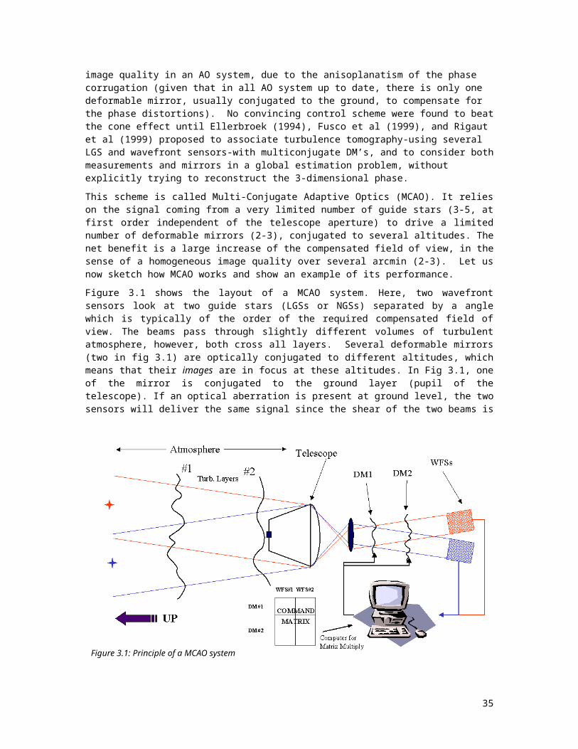
Figure 4.3 illustrates an initial conceptual design for the science optical path through the AO instrument package. This design includes a pair of off-axis parabolas to relay the beam, locations for deformable mirrors optically conjugate to ranges of 0, 4, and 8 kilometers, a tip/tilt mirror optically conjugate to –2 km, two folding flats, and a dichroic which transmits IR wavelengths and reflects visible light into the sensor optical path. The beam print diameter at each DM is approximately 84 mm, which corresponds to 13 actuators across the beam diameter for a 7 mm interactuator spacing.* The total of 9 surfaces in the science optical path is actually less than ALTAIR, and the estimated total emissivity is about 13%. The design is diffraction-limited in H band, as illustrated by the encircled energy curves plotted in Figure 4.4.
The optical design of the LGS wave-sensing path is illustrated in Figure 4.5. The optical relay to the LGS WFS includes a prism with one facet per guide star so that the Shack-Hartmann spots from all of the sources may be placed side-by-side on a single CCD array, as illustrated in Figure 4.6. Assuming four by four pixels per Hartmann spot and a lenslet array of up to 16 by 16 subapertures, up to four guide stars may be sensed using a single 128 by 128 pixel CCD. This example design uses 12 by 12 sampling and easily fits on a 1282 array. High-speed arrays of this size are at a reasonably mature state of development. For example, several have been fabricated by MIT Lincoln Laboratory and are presently in use at the3.5-m
telescope AO system at the USAF Starfire Optical Range. The present read noise of about 12 electrons/pixel at 1500 Hz would need to be reduced by a factor of about two to three to obtain satisfactory measurement accuracy with the anticipated laser guide star signal levels. Increasing the number of subapertures, guide stars, or pixels per Hartmann spot beyond the values listed above would require either the use of multiple WFS cameras or a larger format high-speed CCD array which has not yet been developed.
* Although the present baseline for the MCAO system uses 17 actuators across a beam diameter instead of 13, the analysis and simulation results in Section 3 illustrate that very interesting level of performance may still be achieved with this lesser number. The optical designs presented in this section may be considered an “existence proof” that implementing a useful MCAO capability on Gemini-South is feasible. We do not anticipate significant difficulties in modifying these designs for consistency with higher order DM’s and larger beamprints.
35
Figure 4.3: 3D solid model of the MCAO science path. The path begins at the AO fold mirror in the upper right hand corner (inside of ISS), out through the MCAO, back to the science fold mirror and directed to an up-looking instrument. Four field points are represented here at +/- 1 arc minute radius in the x and y directions. In the MCAO science path, there is first 2 fold mirrors, an off-axis parabola to collimate the beam, three DM’s at 8, 4, and 0KM conjugates (in that order), and an off axis parabola as a final camera optic. This system results in an f/30 beam fed back into the ISS. The Final OAP may serve as a fast tip tilt mirror if larger, average tilts are taken up with the M2 assembly.
36
Figure 4.4: Encircled energy curves for the MCAO science path in H band. Curves are plotted for an ideal diffraction-limited Airy pattern, an on-axis source, and a source off-axis by 1 arc minute.
Figure 4.5: ZEMAX plot of the LGS WFS optical path
The AO instrument package also includes a NGS tip/tilt sensor (not shown), even though at first glance this might seem redundant with the tip/tilt/focus wave-front sensors already included in each Gemini instrument. As described in Section 3 above, however, simultaneous tip/tilt measurements from two different stars provide a direct measurement of tilt anisoplanatism which significantly enhances the performance of the MCAO system. Ideally one would wish to measure the components of tilt anisoplanatism in two different directions using three natural guide stars, and we will explore whether any practical approach can be found to including a second tip/tilt NGS WFS in this sensor package.
At the moment, a NGS WFS with up to 16 by 16 subapertures (not shown) is also included in the system design, since NGS wave-front sensing will always provide peak performance for those applications where a narrow science field contains a bright (mV 15 or better) guide star. Unlike the Altair NGS WFS this sensor does not require a scanning capability to patrol an extended guide field, since NGS AO would only be selected over the MCAO system for small science fields actually containing bright natural guide stars. This sensor may be eliminated (or only needed for system calibration measurements on very bright stars) in the likely event that the MCAO LGS wave-front reconstruction algorithm can be tuned to provide nearly equivalent performance for narrow fields.
Figure 4.7 is a conception of the MCAO optical bench and the associated electronics and DM actuator drivers attached to the ISS. At first glance, the overall cost and weight of the MCAO instrument package appears roughly equivalent to Altair. Some features of the opto-mechanical design are simplified because the WFS pupils are optically conjugate to the telescope primary instead of a range of 6.5 kilometers. Controls and communications interfaces with the A&G system, the tip/tilt system, and the laser guide star system are also very similar to Altair, although the algorithms and interfaces for “blending” tip/tilt measurements from several different guide stars would be more sophisticated. Multiple deformable mirrors do of course represent an increase in cost and complexity when compared to Altair, since the total number of DM actuators could be in the range from 800 to 1250 for a system with 17 actuators across the telescope pupil for each of two or three DM’s.
37
Figure 4.6: Hartmann spot pattern for the LGS WFS. A faceted prism is used to image four sets of spots on a single CCD array
4.5 Signal Processing and Control AlgorithmsThe high-level control requirements for a MCAO system are functionally very similar to any other high order, Shack-Hartmann-based, LGS AO system. These requirements include real-time wave front correction, alignment control of the multiple laser guide stars, and control of opto-mechanical elements in the AO instrument package. Only real-time wave front correction will be discussed in this section, since it is the most demanding task in terms of processing requirements and will drive the cost and the complexity of the MCAO control system. Further material on this subject may be found in Appendix B.
Signal processing functions for real-time wave front correction may be grouped into 5 main tasks:
1. Read the CCD array for each LGS WFS and each NGS tip/tilt WFS, and calibrate the measurements for bias and gain variations;
2. Compute the Shack-Hartmann spot centroids for each subaperture in each WFS, and calibrate these measurements for non-common path optical aberration;
3. Apply the wave front reconstruction matrix to estimate the current value of the closed-loop wave front aberrations;
4. Temporally filter this estimate to determine DM and tip/tilt mirror actuator commands; and
5. Send these commands to the DM’s and the tip/tilt mirror.
The first three tasks may be performed in pipeline mode. For example, the centroid calculations may begin as soon as the first pixel is digitized, and the matrix multiply in step three may begin as soon as the first centroid has been computed. The readout task may also be parallelized for CCD array designs with multiple output ports. These two observations must be exploited to design a processing approach with as little end-to-end latency as possible.
38
Figure 4.7: Conception of the MCAO optical bench and associated electronics attached to the ISS.
Overall signal processing requirements for an MCAO system will be considerably greater than for Altair because the total number of WFS subapertures and DM actuators is much larger. The processing requirements for tasks 1,2, 4, and 5 increase linearly with the total number or subapertures and actuators, but the requirements for task 3 increase as the product of these two numbers. We will therefore focus on task 3, since it will largely determine the total real-time signal processing requirements (the remaining tasks are described in some detail in the appendix). Assume a MCAO AO system with 4 LGS WFS’s with 16 by 16 subapertures, 3 tip/tilt/focus NGS WFS’s with 2 by 2 subapertures, and 3 DM’s with 17, 19, and 21 actuators across the illuminated portion of each mirror. The total number of centroids to be computed each cycle is then 2*(4*162+3*22)=2072; note that the unilluminated subapertures in the corners of each LGS WFS are included in this sum, since they are intermingled with the remaining subapertures in the CCD array output stream and cannot easily be skipped over if a pipeline processing scheme is utilized. The total number of DM actuators is about /4*(212+232+252)=1253 if each deformable mirror includes two guard rings of actuators outside the illuminated region of the mirror. The total number of add/multiply pairs required per reconstruction is therefore about 2.6 million, for an overall processing requirement of 5.2 gigaops at a WFS frame rate of 1000 Hz. The average processing rate is reduced to p/4*5.2 = 4.1 gigaops if the centroids from the unilluminated subapertures are omitted from the matrix multiply, although the need to minimize latency in the AO control loop implies that the computation must still be completed as soon as possible after the output from the final CCD array pixel has been digitized. Reconstructor hardware exists today with at least twice this overall processing capability, although it admittedly occupies two full-size electronics racks and consumes about 600 Watts of power. Still, developing the wave front reconstructor for the MCAO system is an engineering task well within the current state-of-the-art.
In addition to the above real-time tasks, there are a number of background processes to be performed by the MCAO control system:
1. Modal gain optimization if a modal control algorithm is utilized;
2. r0 and fg computation;
3. WFS gain estimation; and
4. Communication with the Data Handling System and other Gemini subsystems.
These tasks will be performed by other processors, and the computation requirements for tasks 2 through 4 scale linearly with the number of subapertures and actuators. Task 1 may not be required at all, since the performance improvement obtained with modal gain optimization may not be great for a LGS AO system with guide stars of fixed and fairly high guide star signal levels.
4.6 Laboratory DemonstrationsThe analysis and simulation results on MCAO system performance summarized in Section 3 above have all been derived using idealized, linear models for wave-front sensors, deformable mirrors, and the wave-front aberrations induced by atmospheric turbulence. This approach is useful for rapidly exploring the performance of a variety of MCAO configurations for a range of operating conditions, but it cannot be used to develop detailed performance specifications for real-world sensors and mirrors. For example, how much optical distortion is allowed in the pupil relay between these two components? Is the tolerance on this parameter more severe than for a conventional AO system due to possible subtleties in the DM-to-WFS influence matrix? More realistic simulations, including wave optics propagation modeling, are planned as a useful next step, but a laboratory demonstration is the best way to validate that MCAO will indeed work with the all of the imperfections of actual hardware.
As illustrated in Figure 4.8, the principal hardware components required in a proof-of-concept laboratory demonstration are:
1. A point source “guide star” with a translation stage or steering mirror to simulate multiple sources at several points in the field-of-view (multiple fixed sources are also an option);
2. Multiple phase screens to simulate a distributed atmosphere;
39
3. A telescope producing a real image of the simulated guide star, followed by relay optics to reimage the telescope pupil and the phase screens;
4. Multiple deformable mirrors placed at several of these conjugate locations;
5. A second optical relay to re-image the pupil onto a wave-front sensor;
6. A wave-front sensor, which must incorporate either a scan mirror or a faceted prism as in Figure xxx to enable wave-front measurements using sources in several difference directions;
7. A control computer to drive the scan mirrors, compute gradients from the WFS intensity measurements, and reconstruct and apply DM actuator commands from the wave-front gradients; and
8. An imaging camera to evaluate guide star image quality with and without adaptive optics compensation.
Figure 4.8: Unfolded Optical Schematic of a laboratory MCAO demonstration
Apart from the deformable mirrors, none of these components need be particularly expensive for a non-real-time demonstration with fixed phase screens. The control computer may be a PC with appropriate interface cards to the cameras and DM actuator drivers. The requirements for camera read time and read noise are very relaxed. The deformable mirrors, however, may represent a significant expense and will determine the overall cost of the demonstration. Three alternatives are under consideration:
1. One might argue that any AO system for Cerro Pachon will require at least one high-order deformable mirror, and the first DM should therefore not be considered a cost of the demonstration. A sufficiently high-order DM, say 21 by 21 actuators, could actually simulate two low-order DM’s using the optical configuration illustrated schematically in Figure yyy. Unfortunately, the lead time necessary to procure a high-order DM could significantly delay the demonstration and the entire MCAO program as well.
2. Relatively inexpensive low order DM’s are becoming available. Their optical quality and actuator influence function characteristics would need to be consistent with a convincing MCAO demonstration designed to achieve at least near-diffraction-limited image quality. Mirrors with a poor surface figure, but satisfactory influence functions, might conceivably be used in a MCAO test to demonstrate wide-field-of-view correction of wave-front distortions to consistent (but large) static residuals.
3. Deformable mirrors already in existence could be temporarily borrowed for a demonstration. The above comments on mirror performance requirements apply here as well.
We will review the above options, and develop a conceptual design for a MCAO laboratory demonstration in time for presentation to the next meeting of the Gemini board.
40
Source WFS
Scori
BX
T/T mirror
Pupil Stop
Pupil Relay
Phase Screens
“Telescope”
Pupil Relay
DM’s
Pupil Relay
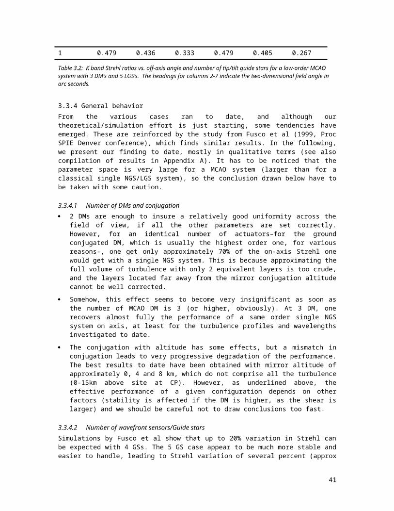
5 Schedule(Cost information has been stripped out of this version)
Figure 5.1 plots a tentative schedule for the MCAO program. Milestones in this schedule include a conceptual design review in March 2000, PDR’s for the laser system and the AO instrument package in December 2000, and CDR’s in December 2001. Subsystem fabrication continues until June 2003, and is followed by 20 weeks of system integration and 20 more weeks of commissioning. Science handover occurs in March of 2004. Note that the MCAO laboratory demonstration is scheduled as part of the preliminary design phase of the AO instrument package, and the critical design phase of the laser system includes a “risk reduction prototyping” task.
41
ID Task Name Duration1 CP LGS MCAO System 1632 days
2 Conceptual Design 632 days
3 CP Site Charac terization 261 days
4 Science and System Implimentation Review 65 days
5 CoD Forum 1 day
6 Review Forum 22 days
7 System Concept Development 152 days
8 System Requirements Review (Gemini Board) 1 day
9 System Conceptual Design 87 days
10 Conceptual Design Review 0 days
11 Subsystem Requirements and Interface Description44 days
12 AO Instrument Package 799 days
13 Preliminary Design Phase 141 days
14 Preliminary Design 140 days
15 Lab Demo 140 days
16 Integration and Test Planning 120 days
17 Preliminary Design Review(s) 1 day
18 Detailed Design Phase 258 days
19 Subsystem Detailed Design 257 days
20 Integration and test planning 160 days
21 Critical Design Review(s) 1 day
22 Fabrication Phase 400 days
23 Fabrication of Subsystems 300 days
24 I, T, & C Proceedures 200 days
25 Operational Software Implementation 300 days
26 Integration and Test 100 days
27 Laser System 799 days
28 Preliminary Design Phase 141 days
29 Preliminary Design 140 days
30 Integration and Test Planning 140 days
31 Preliminary Design Review(s) 1 day
32 Detailed Design Phase 258 days
33 Subsystem Detailed Design 257 days
34 Risk Reduction Prototyping 257 days
35 Integration and Test Planning 160 days
36 Critical Design Review(s) 1 day
37 Fabrication Phase 400 days
38 Fabrication of Subsystems 300 days
39 I, T, & C Proceedures 200 days
40 Operational Software Implementation 300 days
41 Integration and Test 100 days
42 System Integration Phase 201 days
43 System Integration and Tes t 100 days
44 Commiss ioning 100 days
45 Science Handover 1 day
3/31
12/14
12/11
12/14
12/11
3/31
J F M A M J J A S O N D J F M A M J J A S O N D J F M A M J J A S O N D J F M A M J J A S O N D J F M A M J J A S O N D J F M A M1999 2000 2001 2002 2003 2004
Figure 5.1 MCAO Program Schedule
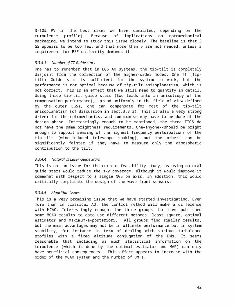
6 Impact on the Gemini Instrumentation Program We now briefly discuss the impact of a MCAOS on the Gemini Instrumentation Program. For additional information the reader is referred to the presentation to the September 1999 Instrumentation Program the Gemini AO Program (see Appendix).
The current On-Going instrumentation program is set up for a classical Altair-class adaptive optics system at Cerro Pachon in 2003. Instruments at the southern telescope with AO-optimized capabilities are the NIR Coronographic Imager, the integral-field spectrograph (NIFS), and the small-field IR MOS. Under the current OGIP, the first of these instruments is not available until 2002 although some instruments could make limited use of a system earlier (eg. GMOS-S in 2001) (Figure 6.1).
Title:Graphics produced by IDLCreator:IDL Version 5.2 (sunos sparc)Preview:This EPS picture was not savedwith a preview included in it.Comment:This EPS picture will print to aPostScript printer, but not toother types of printers.
Figure 6.1. Summary of the time line for the instruments in the current OGIP3.
Under the proposed AO plan, a MCAOS could be on the telescope as early as mid-2003. The principle issues for the OGIP in the context of a MCAO at Pachon are as follows:
(1) AO Gap at Pachon until MCAO is online
(2) Timing of a MCAO with respect to NIR C/I and NIFS
(3) Cost of the program
(4) Focal-plane instrument support for MCAO
6.1 Filling the AO Gap at CPWhether or not we implement a MCAOS, there is an AO gap from handover to 2003/4 when the facility AO system comes online at Pachon. As part of the overall Gemini AO Program we intend to bring a visitor instrument Hokupaa-85 (a clone of the University of Hawaii's planned 85-element upgrade to Hokupa'a) to Gemini-South. Currently, a proposal has been submitted to NSF to fund the cost of the duplication of the AOS. The proposed system includes the following:
1. Duplicate opto-mechanical design of the upgraded Hokupa'a. This will be a stand-along visitor instrument and as such will not feed a beam back into the ISS. Rather we plan to duplicate QUIRC as the default imager. Note that the opto-mechanical design will allow for a single variable conjugate correction.
3 Adapted from F. Gillett's presentation at the Spring 1999 Instrument Forum.
42
2. LGS upgrade for Hokupa'a-85. Gemini will supply the components to upgrade Hokupa'a-85 to include a LGS capability. This includes the laser, launching facilities, and components specific to the LGS inside Hokupaa-85 (eg. a tip/tilt tracker). Note that since Hokupaa-85 is based on avalanche-photodiodes, the laser power requirements for the LGS are greatly reduced. We plan to implement a 2W ring-dye laser pumped by a solid-state doubled YAG laser. At least two manufactures say they will guarantee the 2W output. The cost of the laser system is ~$250k for parts. The figure on the right illustrates the performance and gain in sky coverage for Hokupaa-85LGS. For natural guide stars brighter than 14 are available, the system is used in NGS mode. When the natural guide star is fainter (down to ~19), the LGS mode is used. The calculation presented in Figure 6.2 here are in the H-band under 0.7'' seeing.
The Hokupaa-85 plus LGS/AOS is expected to be ready for use on the southern telescope around operational handover (mid 2001). It will deliver near diffraction-limited resolutions throughout the near-IR and will bring a capability unmatched in the south. While the VLT AOS (NAOS) has a similar order of performance (or slightly better), it will be limited in sky coverage by it's wavefront sensor's CCD detector. If previous ESO plans are followed for the LGS, then the scheduled upgrade of NAOS to LGS is in 2003. This leaves at least a two-year window where Hokupaa-85 LGS will be the only capability in the southern hemisphere with these resolutions.
As this is a visiting instrument a focal-plane instrument is required. A copy of QUIRC is being explored and we estimate it's cost to be $300-400k. In addition, Hokupaa-85 will be well matched to CIRPASS the J-band IFU spectrograph. This capability in J is unmatched even by the VLT facility IFU/AOS (SINFONI) since it is built around a 36-element AOS.
In addition to bringing a LGS/AOS to the southern telescope early, this program provides a method to step up the experience of the Gemini AO team in implementing LGSs. Other than the laser and laser location, the LGS for Hokupaa-85 will be similar to the MK-LGS and CP-LGS implementations. By implementing this system first at Pachon, we will gain greater access to the telescope with a smaller impact on the user community (prior to handover) and develop the expertise on a simpler LGS/AOS system.
6.2 Timing of a MCAO with respect to the OGIPThe NIR Coronographic imager is intended for use with an adaptive optics feed. Its field is narrow and much of its intended scientific use is around bright stars. This translates into an AOS requirement of an on-axis NGS wavefront sensor and a high-order correction. These requirements do not preclude the use of the C/I with a MCAOS. However, in lieu of the increased scattered light, a dedicated AOS internal to the C/I may be preferred. As such, the NIR C/I team is exploring ways to package an internal AOS in the C/I. The question remains whether there are sufficient funds in the C/I funding to provide such an AOS.
The MCAOS would require spectroscopic capabilities as well as an imager. The MCAOS is naturally matched with an IRIS-2g/Flamingos-II IR MOS instrument. This provides a multiplexing spectroscopic capability with a wide-field imaging mode but with undersample pixels. Assuming that the IRIS-2g/Flamingos-II spectrograph has 0.1''/pixel, R=3500, and a 0.3'' slit with a f/16 feed, an f/30 feed from a MCAOS will give a pixel size of 0.05''/pixel and a field of view of 1.7' FOV. This is extremely well matched to the MCAOS field although still undersample spatially. For some objects (eg. faint resolved objects), this undersampling can be desirable.
43
Title:Graphics produced by IDLCreator:IDL Version 5.2 (sunos sparc)Preview:This EPS picture was not savedwith a preview included in it.Comment:This EPS picture will print to aPostScript printer, but not toother types of printers.
Figure 6.2. The expected performance of the Hokupaa-85 + LGS system at Cerro Pachon

The narrow-field integral-field spectrograph (NIFS) is currently designed to be fed by an AOS. Its small plate scale/field and KISS philosophy implies that if NIFS did not have an AO-corrected beam, its performance would be limited. Again, NIFS is not precluded from being fed by a MCAO although the timing of the MCAO puts it at least a year behind NIFS. A possible solution to note is swapping GNIRS and NIFS between telescopes where Altair would fed NIFS. Note however that the focal ratio of the output beam from the MCAOS may not be f/16.
In lieu of the capabilities of the Wide Field IRMOS and NIFS, what role will the Narrow Field-IRMOS play?
A wide-field (2' of MCAO) imager with critically sampled pixel scales requires a detector with 8k x 8k pixels to cover the field of view at 1.25 microns. Such detectors, or at least mosaics to this size, will be developed for NGST, so Gemini could wait for this development. However, the issue remains whether such a capability would be competitive in an NGST-era. On one hand an MCAOS in 2003/4 would have several year advantage over NGST. On the other hand, we would have to wait for NGST to develop the technologies. Still, the MCAO will need some form of an imager during the 3-4 years prior to the scheduled launch of NGST. While a 2k x 2k detector array with critically sampled pixels in J only subtends a 30'' x 30'' field of view, imaging/photometry still benefits greatly from the consistency of the PSF. A possible option is to retrofit (or design in) a 2k+ detector into one of the current imagers.
Questions:
(1) Is imaging over the entire field of view required? At what pixel scale?
(2) What will become of the Narrow Field-MOS in light of a MCAOS+WF IRMOS/NIFS?
(3) What technologies are being developed for NGST that we leverage?
(4) Upgrading current imagers to larger detectors (NIRI, C/I, ??)?
44

Appendix A
Numerical Simulation Results
Compilation of results from the “covariance code”
This appendix reports a selection of results of the performance simulations of a MCAO system. The standard parameters for these results are as follows:
Cn2 profile deduced from a fit to a median Cerro-Pachon profile, r0=0.155m at 0.5 microns
0 degree zenith angle, performance evaluation at 1.25, 1.6, and 2.2 microns
D=8m with 0.152 fractional central obscuration
Kolmogorov turbulence spectrum with an infinite outer scale
LGS locations: (+/-34,+/-34) arcsec, and (0,0) arcsec for the optional fifth guide star
NGS locations: (0,0) for 1, (+/-24.1,0) for 2, and (+/-24.1,0) and (0,+/-24.1) for 4
The Column headings are as follows:
1 and 2: N LGS and O LGS -- Number of LGS's and order of their WFS's
3 and 4: N NGS and O NGS -- Same for NGS's
5 through 7: N DM, O DM, and H DM --Number, order, and conjugate range of the DM's
8 through 13: Strehl ratio evaluated at positions (x,y) -- evaluation direction in arc sec. The (0,x) values are only listed if they are different from the (x,0) values, which only happens with 2 tip/tilt NGS (see small additional table in 2 DM case). The three rows of Strehl ratio correspond to J (top), H (middle), K (bottom) bands
Table A1: Results from numerical simulations, 1 deformable mirror case
Strehls StrehlsN LGS O LGS N NGS O NGS N DM O DM H DM (0,0) (17,0) (34,0) (0,0) (17,17) (34,34)
0 1 6 1 7 0 0.202 0.098 0.035 0.202 0.061 0.0220.395 0.257 0.123 0.395 0.189 0.0780.591 0.462 0.294 0.591 0.385 0.211
0 1 12 1 13 0 0.553 0.215 0.065 0.553 0.125 0.0360.711 0.409 0.182 0.711 0.291 0.1090.825 0.603 0.368 0.825 0.493 0.257
1 6 1 1 1 7 0 0.18 0.096 0.037 0.18 0.062 0.0230.369 0.252 0.128 0.369 0.19 0.0830.569 0.456 0.301 0.569 0.386 0.22
1 12 1 1 1 13 0 0.466 0.214 0.7 0.466 0.13 0.040.644 0.406 0.192 0.644 0.297 0.1180.781 0.599 0.381 0.781 0.498 0.271
45
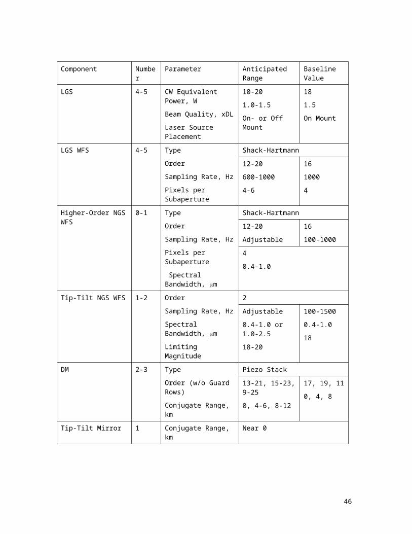
Table A2: Results of numerical simulation, 2 deformable mirror case
Strehls StrehlsN LGS O LGS N NGS O NGS N DM O DM H DM (0,0) (17,0) (34,0) (0,0) (17,17) (34,34)
4 with t/t 6 0 2 7,9 0,8 0.101 0.106 0.103 0.101 0.114 0.1090.262 0.27 0.266 0.262 0.282 0.2740.467 0.476 0.472 0.467 0.486 0.48
4 6 1 1 2 7,9 0,8 0.108 0.086 0.051 0.108 0.075 0.0390.27 0.034 0.156 0.273 0.21 0.1190.479 0.436 0.333 0.479 0.405 0.267
4 6 2 1 2 7,9 0,8 0.111 0.118 0.112 0.111 0.105 0.0710.279 0.288 0.28 0.279 0.267 0.1980.485 0.495 0.486 0.485 0.471 0.386
4 6 4 1 2 7,9 0,8 0.117 0.123 0.117 0.117 0.131 0.110.287 0.296 0.287 0.287 0.306 0.2760.493 0.502 0.493 0.493 0.512 0.482
4 12 4 1 2 13,9 0,8 0.293 0.297 0.276 0.293 0.311 0.2630.492 0.496 0.476 0.492 0.51 0.4610.67 0.673 0.657 0.67 0.684 0.645
5 with t/t 6 0 2 7,9 0,8 0.168 0.154 0.131 0.168 0.147 0.110.355 0.338 0.306 0.355 0.329 0.2750.556 0.541 0.512 0.556 0.533 0.481
5 6 1 1 2 7,9 0,8 0.172 0.12 0.062 0.172 0.093 0.0390.36 0.287 0.177 0.36 0.241 0.120.561 0.49 0.359 0.561 0.44 0.269
5 6 2 1 2 7,9 0,8 0.178 0.166 0.141 0.178 0.133 0.0720.368 0.353 0.32 0.368 0.307 0.20.568 0.555 0.525 0.568 0.511 0.391
5 6 4 1 2 7,9 0,8 0.189 0.174 0.146 0.189 0.166 0.1120.38 0.363 0.328 0.38 0.383 0.280.578 0.564 0.532 0.578 0.555 0.485
5 12 4 1 2 13,9 0,8 0.513 0.433 0.354 0.513 0.399 0.2640.681 0.618 0.55 0.681 0.59 0.4620.805 0.762 0.714 0.805 0.743 0.646
Table A2 Continued
StrehlsN LGS O LGS N NGS O NGS N DM O DM H DM (0,0) (0,17) (0,34)
4 6 2 1 2 7,9 0,8 0.111 0.098 0.070.279 0.256 0.1980.485 0.46 0.387
5 6 2 1 2 7,9 0,8 0.178 0.138 0.0870.368 0.313 0.2270.568 0.517 0.42
46

Table A3 : Results of numerical simulation with 3 deformable mirrors
Strehls StrehlsN LGS O LGS N NGS O NGS N DM O DM H DM (0,0) (17,0) (34,0) (0,0) (17,17) (34,34)
0.103 0.104 0.093 0.103 0.107 0.0914 12 4 2 3 7,8,9 0,4,8 0.262 0.264 0.249 0.262 0.271 0.243
0.466 0.469 0.454 0.466 0.476 0.4470.25 0.249 0.243 0.25 0.262 0.264
4 12 4 2 3 13,8,9 0,4,8 0.446 0.447 0.44 0.446 0.461 0.4610.632 0.634 0.628 0.632 0.645 0.645
4 12 4 2 3 13,15,9 0,4,8
4 12 4 2 3 13,15,17 0,4,8
0.245 0.208 0.171 0.245 0.187 0.1325 12 4 2 3 7,8,9 0,4,8 0.441 0.402 0.358 0.441 0.378 0.307
0.629 0.597 0.56 0.629 0.577 0.5110.535 0.44 0.407 0.535 0.403 0.354
5 12 4 2 3 13,8,9 0,4,8 0.698 0.624 0.596 0.698 0.593 0.550.817 0.767 0.747 0.817 0.745 0.713
47
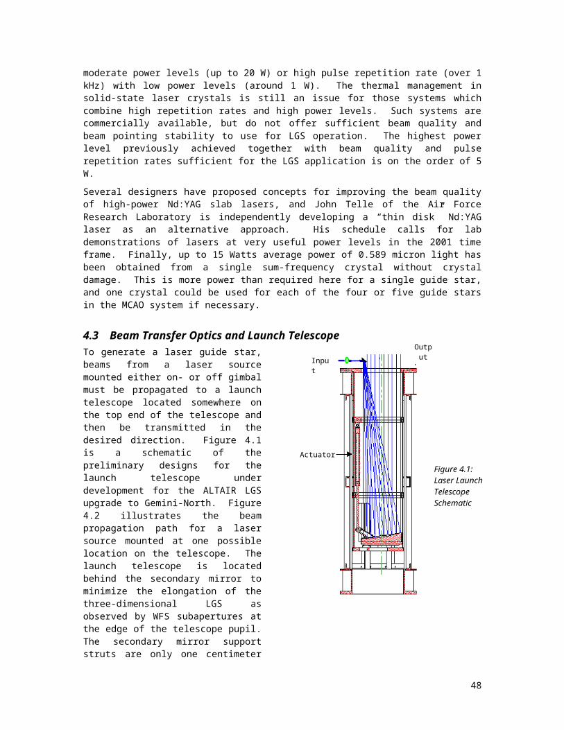
Appendix B
MCAOS Optical Model. Additionnal Zemax Drawings
Appendix B.1 Science Path
48
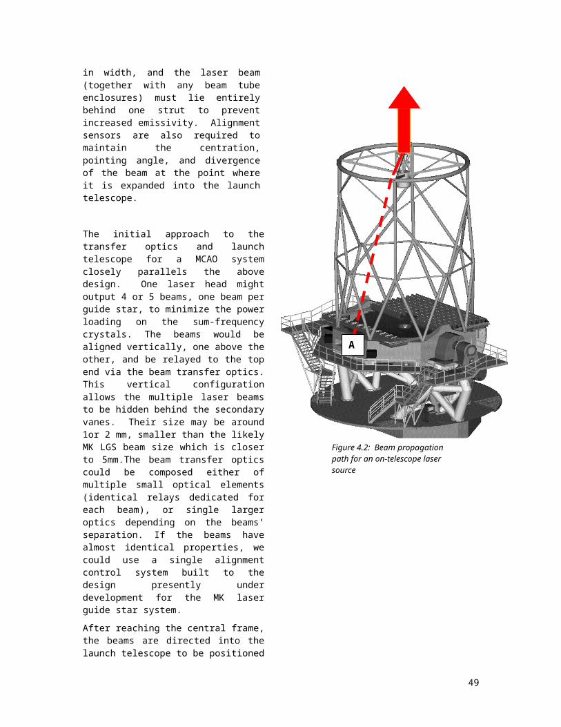
49
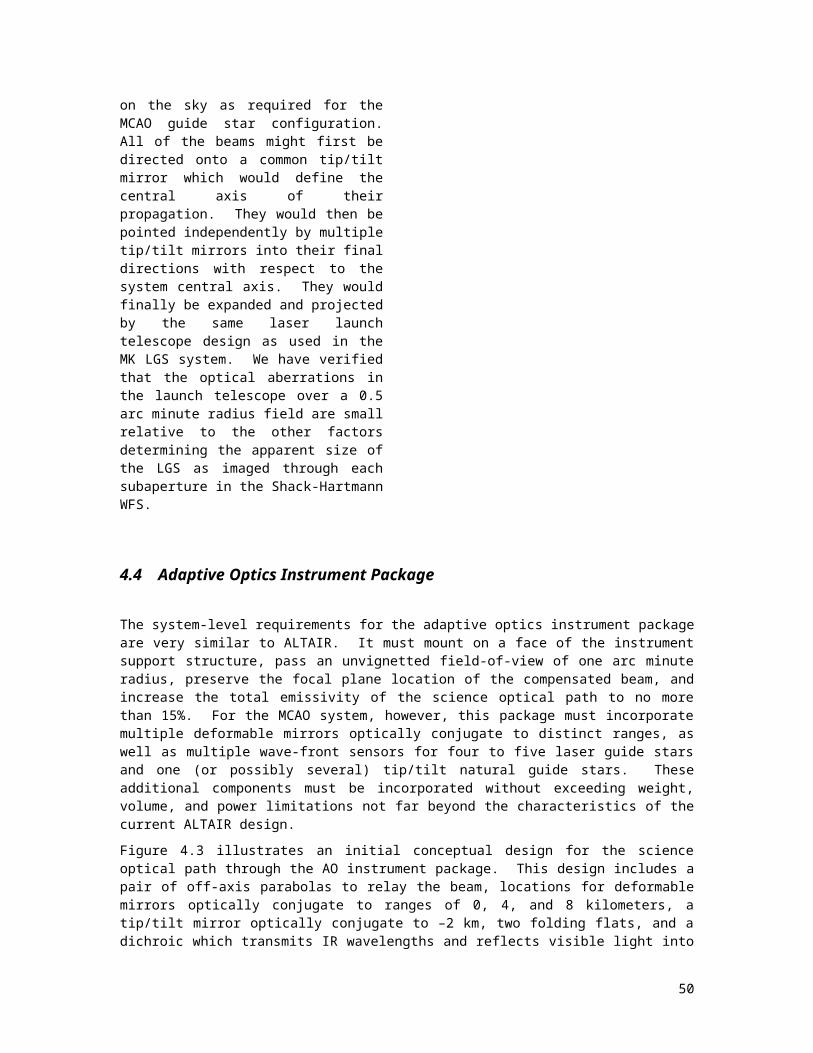
APPENDIX B.2 WFS PATH
50
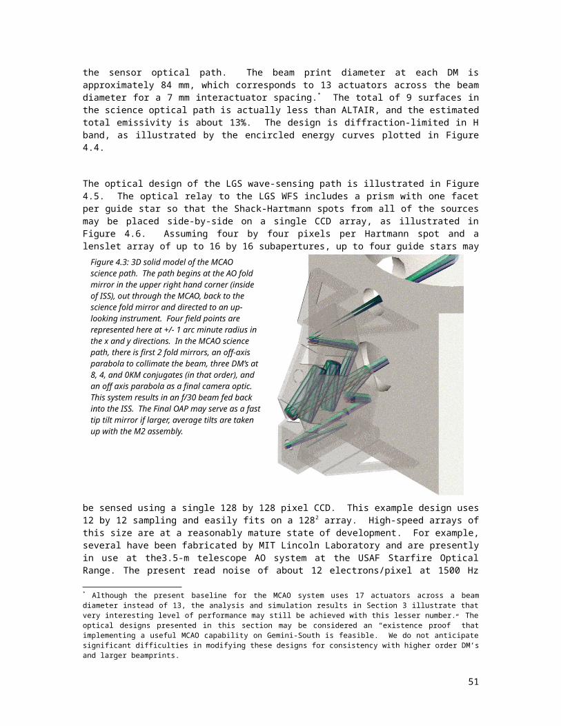
51

Appendix CReal Time Processing and AlgorithmsAppendix C.1 IntroductionThis section describes the requirements in terms of real time processing and algorithms of the Gemini Multi Conjugate Adaptive Optics System and presents an overview of a solution for the real time computer.
Requirements are based on these following inputs:
The Gemini Multi Conjugate Adaptive Optics System will be composed of:
4 identical Shack Hartmann Wavefront Sensors,
4 lasers guide star,
3 Deformable Mirrors,
1 tip-tilt mirror and a dedicated tip tilt Wavefront Sensor,
and various opto-mechanical assemblies.
The sampling rate for this system will be 1KHz.
The control of such a system will be splitted into 3 different functions:
the real time wavefront correction,
the control of the 4 laser guide stars,
the control of the opto-mechanical elements.
Only the real time wavefront correction function will be studied (requirements and solution) in this section. The two others functions are part of the laser section and part of the opto-mechanical section.
These imputs are considered as a starting point and perhaps will be modified during the study.
Appendix C.2 AcronymsDHS Data Handling Systems
DM Deformable Mirror
LGS Laser Guide Star
MCAO Multi Conjugate Adaptive Optics
SH Shack Hartmann
TTM Tip Tilt Mirror
WFS Wavefront Sensor
Appendix C.3 Real time wavefront correction requirementsThe real time wavefront correction requirements can be synthesized into these 6 main tasks:
read the CCD for each WFS including the dedicated tip tilt WFS,
compute the centroids for each WFS,
subtract a centroid reference vector and save centroids data into a circular buffer,
apply the control matrix,
52
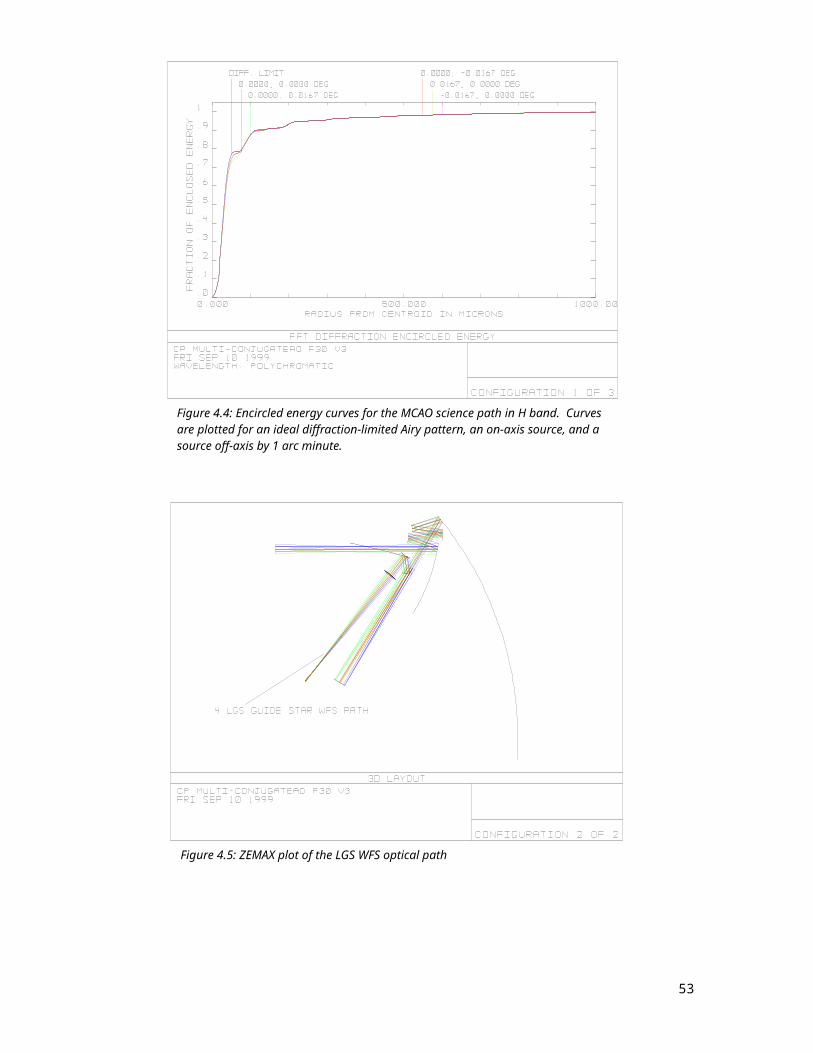
apply a temporal filter and save actuator controls into a circular buffer,
send the data to the DMs and the TTM.
All these tasks have to be performed in 1ms or less and following this order.
However, it is not necessary to wait the end of a task to start the next one. For example the computation of the centroids can be started as soon as we have one pixel. Moreover because of the fact we have 4 WFS, the readout task can be parallelized. These two characteristics have to be exploited to design a very high performant real time computer.
To these tasks, some optimizations and backgrounds tasks have to be added:
modal gain optimization,
r0, t0 computation,
send data to the DHS...
These tasks will have to be performed by other processors.
Let’s describe now the algorithms used for the real time wavefront correction.
Appendix C.3.1 The wavefront sensorsEach of the 4 WFS will be Shack Hartmann type and will be composed by a square lenset array and a low noise and fast CCD. Due to the beam geometry, several subapertures will not be used at each corner. Let m/2 be the number of subapertures of each WFS.
Each subaperture will be composed by 2x2 pixels.
Pixel data will be acquired as short integer values. All further computation will be in float, then the centroid computation will include floating point conversions.
The centroid (Xi, Yi) computation for each subaperture i is very simple and is done after a dark subtraction for each used pixel:
Ai Bi Xi = (( Bi+Di – Ai+Ci ) / ( Ai+Bi+Ci+Di )) - Xiref
Ci Di Yi = (( Ai+Bi – Ci+Di ) / ( Ai+Bi+Ci+Di )) - Yiref
where Ai, Bi, Ci, Di are the pixel values after dark subtraction, Xiref and Yiref the reference position for this subaperture.
The number of centroids for one WFS will be m.
The total number of operations to compute the centroids for the 4 WFS:
8*m short integer subtraction (dark subtraction),
8*m short integer to floating point conversions,
10*m additions and 8*m subtractions,
4*m divisions.
The tip tilt wavefront sensor will be a quadrant detector and the computation of the tip tilt measurement will be performed as one subaperture of the previous 4 WFS.
Example: 20x20 SH WFS
53
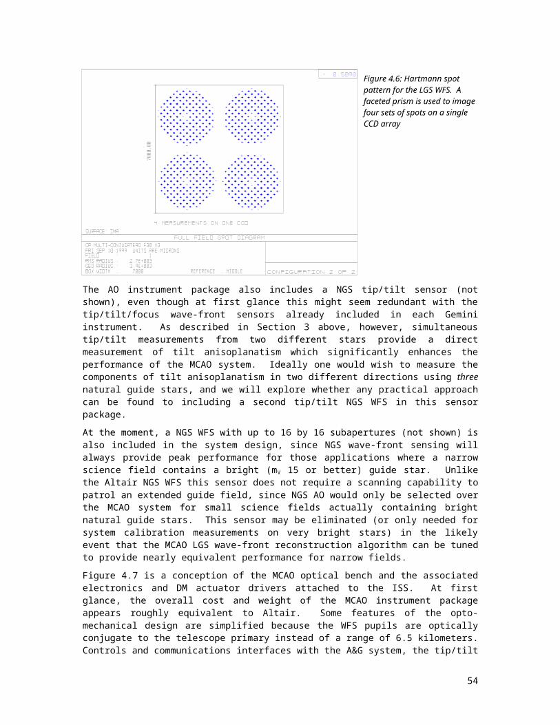
The SH WFS will be composed by a grid of 20x20 subapertures. The CCD will be the Pixel Vision 80x80 pixel elements and 40 outputs CCD called ADAPT3. Each subaperture will be composed by 2x2 pixels and between each rows and columns of subapertures, there will be a gap of 2 pixels.
Because of the geometry of the beam, 21 subapertures will be cancelled at each corner. The total number of subapertures for each WFS will be 316 (m=632) and the corresponding number of pixels to read will be 1264.
The 40 outputs ensure high performance imaging at rates up 1500 frames per second and low noise such 12electrons rms at 1250 frames per second. To acquire the 14 bit serial from the CCD, a dedicated PCI bus interface board is used.
Representation of the 20x20 subapetures Shack Hartmann Wavefront Sensor
The Deformable Mirrors
Let n be the number of actuators of each deformable mirror.
Example:
An option will be to use the Xinetics DM349PMNS4 with 349 actuators (grid of 21x21 actuators with 23 actuators cancelled in each corner).
The Control Matrix
The control matrix allows to compute the actuator commands from the centroids measurements:
54
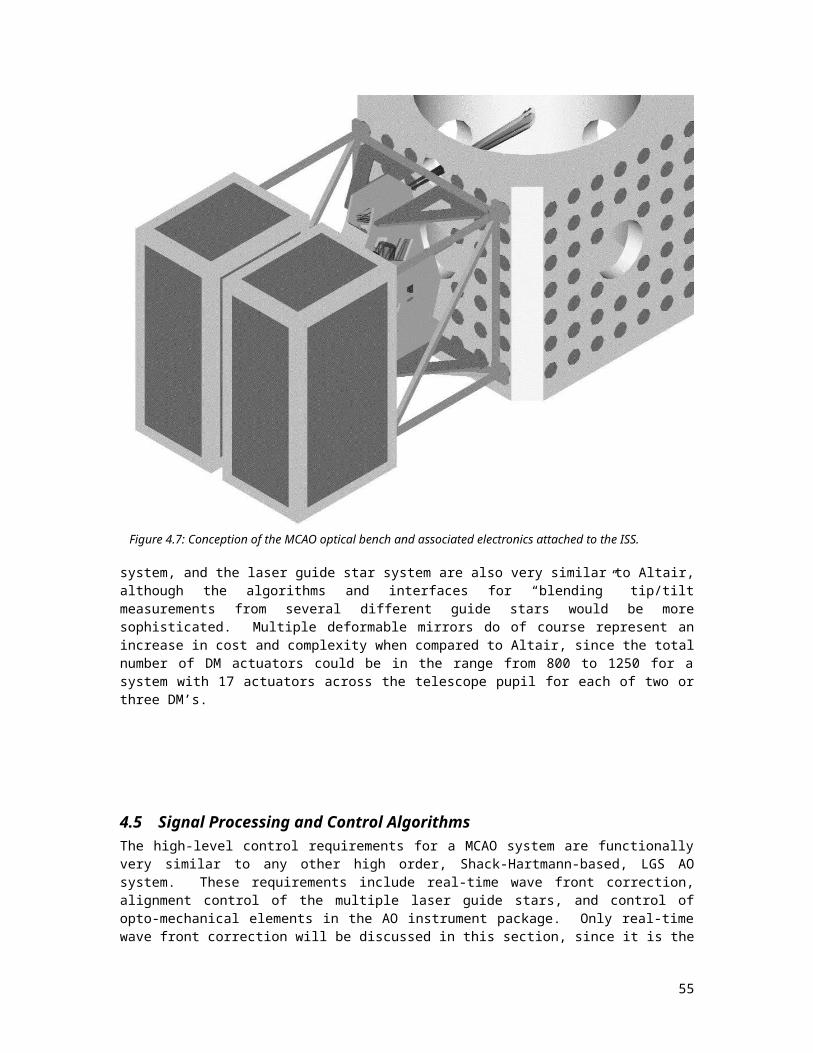
|A> = M |C> (EQ1)
where:
|A> is the vector of the actuator commands for the 3 DMs, the dimension of this vector is then 3*n,
M is the control matrix, which contains 3*n rows and 4*m columns in floating point value,
|C> is the centroid error vector for the 4 WFSs, dimension of this vector is 4*m
To determine this control matrix, first it is necessary to determine the interaction matrix. This matrix defines the set of linear equations between the actuator stroke vector |A> and the centroid measurement vector |C>.
Let |Ci> be the centroids measured when the ist actuator is driven; the interaction matrix consists in the following set of the centroids vectors:
NIM = | |C1>,|Ci>,...|C3*n>| (EQ2)
The process to determine this interaction matrix is a maintenance process and is never done in real time.
However, the control matrix is obtained by a real time background process and updated at a slow rate (each mn or less):
M = O G O-1
NIM-1
(EQ3)
where:
O is the correction mode matrix, this matrix contains the mirror modes for the 3 DMs, this matrix is a square matrix and the dimension is (3*n,3*n).
G is the gain matrix, this matrix is diagonal matrix and each element of the diagonal represents the closed loop gain for the corresponding mirror mode. The dimension of this matrix is (3*n,3*n).
NIM is the interaction matrix of dimension (3*n,4*m).
From real time measurements (centroids and actuator controls), the signal to noise ratio and the temporal behavior of each correction mode is determined and through an optimization process, closed loop gains are recomputed, given a new G matrix.
Apply the control matrix will lead to two different functions:
the real time process which will compute the (EQ1), the number of operations will be 12*n*m operations.
the pseudo real time process which will optimize the closed loop gains, this function will be performed by a single processor (requirement each mn).
A temporal filter is then applied on the actuator controls. Let just do an integrator. This corresponds to add the previous actuator controls to the instantaneous ones. This leads to have 3*n add.
Finally, the data are sent to the DMs through a high speed parallel interface board. This will lead to do some ckecking and conversions before writing the data on the interface board.
Number of operations
The options are:
4 identical 20x20 SH WFS (316 subapertures each – corner subapertures cancelled) and 3 identical 21x21 DMs (349 actuators each – corner actuators cancelled and no guard rings of actuators)
4 identical 16x16 SH WFS (256 subapertures each – corner subapertures not cancelled) and 3 DMs 17x17, 19x19 and 21x21 (1253 actuators with for each DM 2 guard rings of actuators outside the illuminated region of the mirror and corner actuators cancelled)
55
Float add/mult Float add Float sub Float div Short Int sub Conv Total
option 1 2646816 7367 5056 2528 5056 5056 ~5.4 Mop
option 2 2566144 6373 4096 2048 4096 4096 ~5.2 Mop
A benchmark program has been written in C language and allows to estimate the time from the centroid computation to the temporal filtering on the actuator controls. This benchmark program has been tested on a MOTOROLA board MVME2700 equipped with a PowerPC 750 running at 266MHz and the following computation time has been obtained for the option 1 described above : 147.103 ms.
A second benchmark program has been written in C language to estimate time used for the modal gain optimization (modes computation, FFT computation and matrix multiplication). Again this benchmark program has been tested on a MOTOROLA board MVME2700 equipped with a PowerPC 750 running at 266MHz and the following computation time has been obtained for the option 1 described above and with a number of 128 FFT per modes: 39.716 s.
56
Appendix D: Instrument Forum AO program Presentation
57
Title:Microsoft PowerPoint - forum_no_backgrdCreator:PSCRIPT.DRV Version 4.0Preview:This EPS picture was not savedwith a preview included in it.Comment:This EPS picture will print to aPostScript printer, but not toother types of printers.
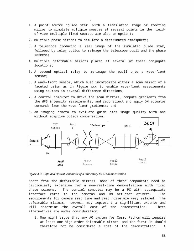
58
Title:Microsoft PowerPoint - forum_no_backgrdCreator:PSCRIPT.DRV Version 4.0Preview:This EPS picture was not savedwith a preview included in it.Comment:This EPS picture will print to aPostScript printer, but not toother types of printers.
59
Title:Microsoft PowerPoint - forum_no_backgrdCreator:PSCRIPT.DRV Version 4.0Preview:This EPS picture was not savedwith a preview included in it.Comment:This EPS picture will print to aPostScript printer, but not toother types of printers.
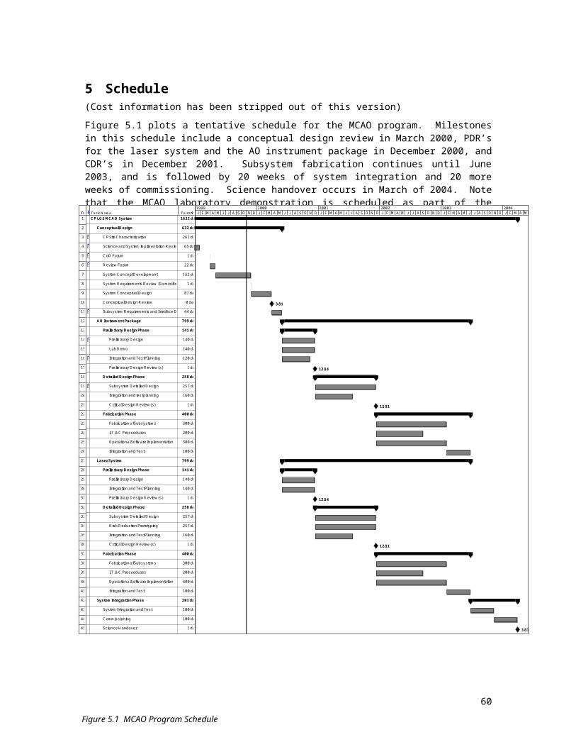
60
Title:Microsoft PowerPoint - forum_no_backgrdCreator:PSCRIPT.DRV Version 4.0Preview:This EPS picture was not savedwith a preview included in it.Comment:This EPS picture will print to aPostScript printer, but not toother types of printers.
61
Title:Microsoft PowerPoint - forum_no_backgrdCreator:PSCRIPT.DRV Version 4.0Preview:This EPS picture was not savedwith a preview included in it.Comment:This EPS picture will print to aPostScript printer, but not toother types of printers.