Embed Size (px)
Citation preview

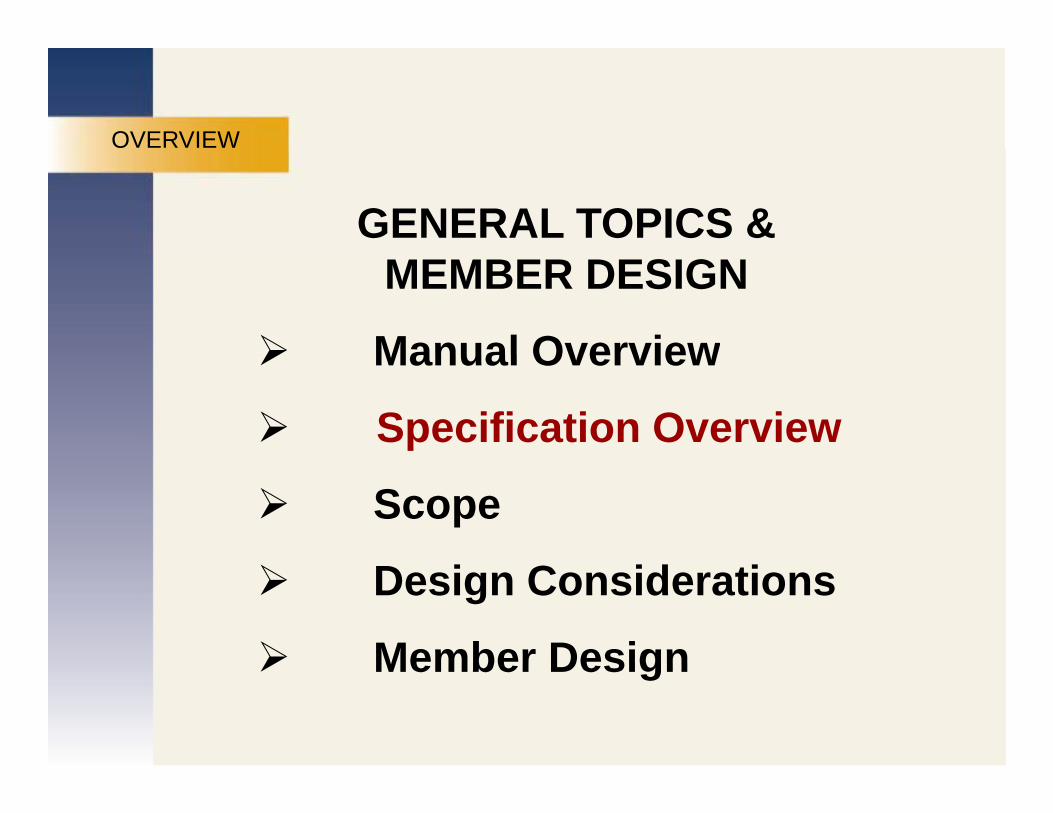
OVERVIEW
GENERAL TOPICS &
MARKETINGMEMBER DESIGN
Manual Overview
PUBLICATIONSManual Overview
Specification Overview
REDESIGNScope
Design Considerations
Member DesignMember Design

OVERVIEW CONNECTION DESIGNCONNECTION DESIGN
2010 Specification
MARKETINGBoltsWelds
PUBLICATIONSConnecting Elements
thREDESIGN14th Ed. Manual
Coped BeamsPrying ActionBracket Plates

MANUAL OVERVIEW
14th Ed. MANUAL TABLE OF CONTENTS
1 Dimensions and PropertiesMANUAL OVERVIEW 1 Dimensions and Properties
2 General Design Considerations
MARKETING3 Design of Flexural Members
PUBLICATIONS4 Design of Compression Members
5 Design of Tension MembersREDESIGN
5 Design of Tension Members
6 Design of Members Subject to Combined Forces
7 Design Considerations for Bolts7 Design Considerations for Bolts
8 Design Considerations for Welds

9 Design of Connecting Elements
10 D i f Si l Sh C tiMANUAL OVERVIEW 10 Design of Simple Shear Connections
11 Design of Partially Restrained Moment Connections
MANUAL OVERVIEW
MARKETING12 Design of Fully Restrained Moment Connections
13 Design of Bracing Connections and
PUBLICATIONS13 Design of Bracing Connections and
Truss Connections
14 Design of Beam Bearing Plates, Col. Base Plates,
REDESIGNg g
Anchor Rods, and Col. Splices
15 Design of Hanger Connections, Bracket Plates, and Crane-Rail Connections
16 Specifications and Codes(Specification RCSC Spec Code)(Specification, RCSC Spec, Code)
17 Miscellaneous Data and Mathematical Information

2010
ANSI/AISC 360-10
MARKETINGPUBLICATIONS 2009
REDESIGNCaption text.
OVERVIEW
GENERAL TOPICS &
MARKETINGMEMBER DESIGN
Manual Overview
PUBLICATIONSManual Overview
Specification Overview
REDESIGNScope
Design Considerations
Member DesignMember Design

Specification for Structural Steel BuildingsSPEC OVERVIEW Buildings
Chapter A. General Provisions
MARKETINGp
Chapter B. Design Requirements
Chapter C Design for Stability
PUBLICATIONSChapter C. Design for Stability
Chapter D. Design of Members for Tension
C f f CREDESIGNChapter E. Design of Members for Compression
Chapter F. Design of Members for Flexure
Chapter G. Design of Members for Shear
Chapter H. Design of Members for Combined Forces and Torsion

Specification for Structural SteelSPEC OVERVIEW Specification for Structural Steel Buildings
Chapter I. Design of Composite Members
MARKETINGp g p
Chapter J. Design of Connections
Chapter K Design of HSS and Box Members
PUBLICATIONSChapter K. Design of HSS and Box Members
Connections
Chapter L. Design for Serviceability
REDESIGNp g S y
Chapter M. Fabrication and Erection
Chapter N Quality Control and Quality AssuranceChapter N. Quality Control and Quality Assurance -NEW

Specification for Structural SteelSPEC OVERVIEW Specification for Structural Steel Buildings
Appendix 1 Design by Inelastic Analysis New
MARKETINGAppendix 1. Design by Inelastic Analysis - New
Appendix 2. Design for Ponding
PUBLICATIONSAppendix 3. Design for Fatigue
Appendix 4. Structural Design for Fire Conditions
REDESIGNAppendix 5. Evaluation of Existing Structures
Appendix 6. Stability Bracing for Columns and Beams
Appendix 7. Alternative Methods of Design for Stability
Appendix 8. Approximate Second-Order Analysis

OVERVIEW
GENERAL TOPICS &
MARKETINGMEMBER DESIGN
Manual Overview
PUBLICATIONSManual Overview
Specification Overview
REDESIGNScope
Design Considerations
Member DesignMember Design
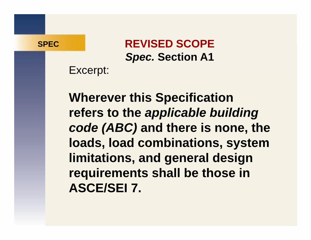
REVISED SCOPESPEC REVISED SCOPESpec. Section A1
Excerpt:
SPEC
MARKETINGp
Wherever this Specification
PUBLICATIONSrefers to the applicable building code (ABC) and there is none, the
REDESIGNloads, load combinations, system limitations, and general design requirements shall be those in ASCE/SEI 7.

REVISED SCOPESPEC REVISED SCOPE
Section A1.1: Seismic Applications
SPEC
MARKETINGSection A1.1: Seismic ApplicationsThe Seismic Provisions shall apply to the design of seismic force resisting
PUBLICATIONSthe design of seismic force resisting systems of structural steel or of structural steel acting compositely
REDESIGNwith reinforced concrete, unless specifically exempted by the
li bl b ildi dapplicable building code.

MANUAL ADDEDMANUAL ADDEDMANUAL SCOPE STATEMENT
MARKETINGThe specification requirements and
PUBLICATIONSp q
other design recommendations and considerations summarized in this
REDESIGNconsiderations summarized in this
Manual apply in general to the design and construction of steel buildings andand construction of steel buildings and
other structures.

MANUAL
MANUAL SCOPE STATEMENTMANUAL SCOPE STATEMENT
AISC Seismic Provisions are not applicable to:• Buildings and other structures in SDC A
MARKETING• Buildings and other structures in SDC B or C with R = 3 systems (steel systems not specifically detailed for
PUBLICATIONSsystems (steel systems not specifically detailed for seismic resistance per ASCE/SEI 7 Table 12.2-1)
• Non building structures similar to buildings with R = 12
REDESIGN• Non-building structures similar to buildings with R = 12 braced-frame systems or R = 1 moment-frame systems; see ASCE/SEI 7 Table 15.4-1
• Non-building structures not similar to buildings (see ASCE/SEI 7 Table 15.4-2), which are designed to meetASCE/SEI 7 Table 15.4 2), which are designed to meet the requirements in other standards entirely

MANUAL
MANUAL SCOPE STATEMENTMANUAL SCOPE STATEMENT
Seismic Provisions are applicable to:
MARKETING• Buildings and other structures in SDC B or C when one of the exemptions for steel seismic force resisting systems above does not apply
PUBLICATIONSsystems above does not apply
• Buildings and other structures in SDC B or C that use it i i f i ti tREDESIGNcomposite seismic force resisting systems
• Buildings in SDC D, E or Fg ,
• Non-building structures in SDC D, E or F when the exemption above does not applyexemption above does not apply

OVERVIEW
GENERAL TOPICS &
MARKETINGMEMBER DESIGN
Manual Overview
PUBLICATIONSManual Overview
Specification Overview
REDESIGNScope
Design Considerations
Member DesignMember Design

DESIGN CONSIDERATIONS
DESIGN CONSIDERATIONS
MARKETING• Shapes Available
PUBLICATIONS• Properties Updated• Referenced Standards/Material
REDESIGN• Structural Integrity• Stability• Stability• Other Topics

MANUAL PART 1 SHAPES AVAILABLEMANUAL PART 1 SHAPES AVAILABLE
(Manual Part 1)
MARKETINGNEW: HP 18 series
HP 16 series
PUBLICATIONSHP 16 series
C4x7.25
REDESIGNMC12x14.3
DELETED: W36x800DELETED: W36x800
See www. aisc.org for availability
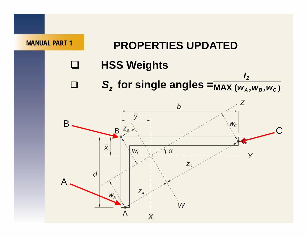
MANUAL PART 1 PROPERTIES UPDATEDMANUAL PART 1 PROPERTIES UPDATED
HSS WeightsI
MARKETINGSz for single angles = , , )MAX (
Z
A B C
Iw w w
PUBLICATIONSBC
REDESIGNC
A

A2. REFERENCED SPECIFICATIONS, CODES AND STANDARDS
SPEC
ASCE/SEI 7-2010
SPEC
MARKETINGACI 318-08
PUBLICATIONSAWS D1.1:2010
REDESIGNNew Material: ASTM A1043/A1043M• Seismic Applications
F / F 0 8• Fy / Fu = 0.8• Charpy V-notch toughness is 40 ft-lb@70°F
Testing with ASTM A673 Freq HTesting with ASTM A673, Freq. H

B2. LIMIT STATES STRUCTURAL INTEGRITY OF CONNECTIONS
SPECSPEC
Based on a minimum nominal strength T
MARKETINGnominal strength, Tn, unless ABC specifies Vu or Va
PUBLICATIONSIgnore limit states based on limiting d f i / i ldiREDESIGNdeformations/yielding
Bearing bolts in
Tn
Bearing bolts in SSLP permitted with bolts assumed at endbolts assumed at end of slot

SPECSTRUCTURAL INTEGRITY OF
CONNECTIONS
SPEC
MARKETINGRef: Geschwindner and Gustafson, Engineering Journal, 3rd Q. 2010
PUBLICATIONS2009 IBC specifies for high-rise buildings (Occ Cat. III and IV):
REDESIGNbuildings (Occ Cat. III and IV):
Tn ≥ Va ≥ 10 kips (ASD)a
Tn ≥ (2/3) Vu ≥ 10 kips (LRFD)

DESIGN FOR STABILITYCHAPTER CCHAPTER C AND APPENDIX 7
CHAPTER C
MARKETINGCHAPTER C DIRECT ANALYSIS METHOD
OR
PUBLICATIONSOR
APPENDIX 7 EFFECTIVE LENGTH METHOD
REDESIGNOR
1ST-ORDER ANALYSIS METHOD
APPENDIX 8 APPROX. 2ND ORDERAPPENDIX 8 APPROX. 2 ORDER ANALYSIS (B1-B2 procedure)

DESIGN FOR STABILITYCHAPTER C
C1. General Stability Requirements
CHAPTER C
MARKETINGStability Design Method must account for:
1) Fl l Sh A i l b d f ti
PUBLICATIONS1) Flexural, Shear, Axial member deformations
2) Second-order effects (P-Δ & P-δ)
REDESIGN) ( )

MARKETINGPUBLICATIONSREDESIGN

DESIGN FOR STABILITYSPEC
C1. General Stability Requirements
SPEC
MARKETINGStability Design Method must account for:
1) Fl l Sh A i l b d f ti
PUBLICATIONS1) Flexural, Shear, Axial member deformations
2) Second-order effects (P-Δ & P-δ)
REDESIGN) ( )
3) Geometric Imperfections
4) Stiffness Reductions due to Inelasticity(2005: due to residual stresses)
5) Uncertainty in Stiffness and Strength - New

DESIGN FOR STABILITYSPEC DESIGN FOR STABILITYC2. Calculation of Required Strengths-DM
Ok t N l t P h
SPEC
MARKETINGOkay to Neglect P - δ when:1) Gravity loads supported by vertical columns,
walls, frames
PUBLICATIONS,
2) δmax / Δmax ≤ 1.7 in all stories
REDESIGN3) 1/3 or less of the total gravity load on structure is supported by columns that are
t f th t i ti f i thpart of the moment-resisting frames in the direction of translation
Not permitted for members under compression & flexure
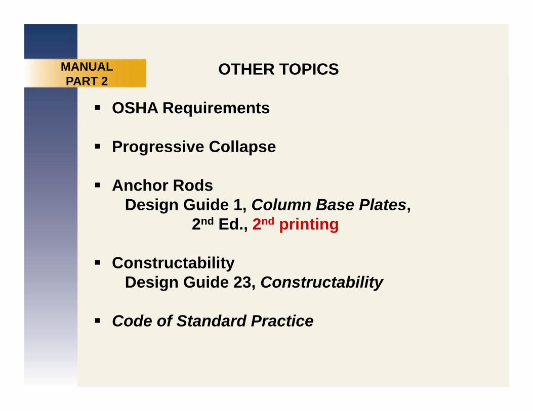
OTHER TOPICSMANUAL
OSHA RequirementsPART 2
MARKETINGProgressive Collapse
A h R d
PUBLICATIONSAnchor Rods
Design Guide 1, Column Base Plates, 2nd Ed., 2nd printing
REDESIGN, p g
Constructability Design Guide 23 ConstructabilityDesign Guide 23, Constructability
Code of Standard Practice

2010 Code of Standard Practice for SteelMANUAL 2010 Code of Standard Practice for Steel Buildings and Bridges
MANUAL
MARKETINGSection 3.1.2 (Connection Design)3 options for each connection design:
PUBLICATIONS1) Complete design on structural design drawings
O i th t t l d i d iREDESIGNOr in the structural design drawings or
specifications, designate:2) Selected or completed by experienced
detailerOr3) Designed by a licensed P E working for the3) Designed by a licensed P.E. working for the
fabricator

OTHER TOPICS
OSHA Requirements (MANUAL PART 2)Progressive Collapse
MARKETINGProgressive CollapseAnchor Rods
Design Guide 1, Column Base Plates, 2 d Ed 2 d i ti
PUBLICATIONS2nd Ed., 2nd printing
Constructability Design Guide 23, Constructability
REDESIGNg , y
Code of Standard Practice Section 3.1.2Connection design responsibility
Quality Control and Quality AssuranceQuality Control and Quality AssuranceSpec. Chapter N

SPEC
NEWCHAPTER N: QUALITY CONTROL SPEC Q
AND QUALITY ASSURANCE
WHY?
MARKETINGWHY?
1) IBC Chapter 17 – applied inconsistently2) Requests from BSSC NCSEA and others
PUBLICATIONS2) Requests from BSSC, NCSEA and others3) Needed a non-seismic version of
2005 Seismic Provisions Appendix Q
REDESIGN2005 Seismic Provisions Appendix Q
4) Goal: Provide a uniform plan with a relatively high level of assurance, and effective, consistent e e o assu a ce, a d e ect e, co s ste trequirements

SPEC QUALITY CONTROL SPECAND QUALITY ASSURANCE
MARKETINGN1. SCOPE
Minim m req irements
PUBLICATIONS• Minimum requirements
• Quality Control by fabricator & erector
REDESIGN• Quality Assurance by others when
requiredrequired
• Non-destructive testing by QA firm, except as permitted in N7except as permitted in N7

CHAPTER N QUALITY CONTROL CHAPTER NAND QUALITY ASSURANCE
N1. Scope
MARKETINGN2. Fabricator’s and erector’s quality control programN3. Fabricator’s and erector’s documents
PUBLICATIONSN4. Inspection and non-destructive testing personnel
N5. Minimum requirements for inspection of structural l b ildiREDESIGNsteel buildings
N6. Minimum requirements for inspection of composite constructionconstruction
N7. Approved fabricators and erectors
N8. Non-conforming materials and workmanshipN8. Non conforming materials and workmanship

CHAPTER N QUALITY CONTROL CHAPTER NAND QUALITY ASSURANCE
SECTIONS N5 AND N6
MARKETINGSECTIONS N5 AND N6
PUBLICATIONSAISC: PERFORM (P) OBSERVE (O)
REDESIGNIBC: CONTINUOUS PERIODIC
2012 IBC CHAP 17 ADOPTS CHAPTER N

OVERVIEW
GENERAL TOPICS &
MARKETINGMEMBER DESIGN
Manual Overview
PUBLICATIONSManual Overview
Specification Overview
REDESIGNScope
Design Considerations
Member DesignMember Design

SPEC
MEMBER DESIGN
MARKETING• Compression Members
PUBLICATIONS• Flexural Members• Members and Combined ForcesREDESIGN
• Members and Combined Forces• Composite Members

SPEC CHAPTER E.
DESIGN OF MEMBERS FOR COMPRESSIONE1 General Provisions
MARKETINGE1. General ProvisionsE2. Effective LengthE3 Fl l B kli f M b With t
PUBLICATIONSE3. Flexural Buckling of Members Without
Slender ElementsE4 T i l d Fl l T i l B kli fREDESIGNE4. Torsional and Flexural-Torsional Buckling of
Members without Slender ElementsE5 Si l A l C i M bE5. Single Angle Compression MembersE6. Built-Up MembersE7. Members with Slender Elements

B4 1 CLASSIFICATION OF SECTIONSSPEC B4.1. CLASSIFICATION OF SECTIONS FOR LOCAL BUCKLING
SPEC
MARKETINGTable B4.1a: Limiting Width-to-Thickness
Ratios of Members Subject to Axial
PUBLICATIONSj
Compression
N l d Sl dREDESIGNNon-slender vs. Slenderλ ≤ λr λ > λr

MARKETINGPUBLICATIONSREDESIGN

DESIGN OF MEMBERS FORCHAPTER E DESIGN OF MEMBERS FOR COMPRESSION
CHAPTER E
MARKETINGE3. FLEXURAL BUCKLING OF MEMBERS
WITHOUT SLENDER ELEMENTS
PUBLICATIONS(a) When ⎞⎟⎠
≤⎛
≤⎜⎝
. .o4 71 r 2 25y
y
e
FF
KL Er F
REDESIGNIn 2005: (or Fe ≥ 0.44Fy)
⎡ ⎤= −⎢ ⎥⎢ ⎥
. ( )0 658 E3 2y
e
FF
cr yF F⎢ ⎥⎣ ⎦
y

MANUALE5. SINGLE ANGLE COMPRESSION MEMBERS
(Eccentrically Loaded)
MANUAL
MARKETINGTABLE 4-12
Based on . ( )+ + ≤ −1 0 H2 1ra rbw rbzf f f
PUBLICATIONS. ( )+ + ≤ 1 0 H2 1
ca cbw cbzF F F
REDESIGN[insert Table 4-12]

DESIGN OF MEMBERS FOR CHAPTER ECOMPRESSION
E6 BUILT-UP MEMBERS
CHAPTER E
MARKETINGE6. BUILT-UP MEMBERS1. Compressive Strength
( ) F i t di t t th t b lt d
PUBLICATIONS(a) For intermediate connectors that are bolted
snug-tight:
⎛ ⎞⎛ ⎞ ⎛ ⎞22
REDESIGN⎛ ⎞⎛ ⎞ ⎛ ⎞= + −⎜ ⎟ ⎜ ⎟ ⎜ ⎟⎝ ⎠ ⎝ ⎠ ⎝ ⎠
( )22
E6 1im o
KL KL ar r r
(same as 2005)

DESIGN OF MEMBERS FOR CHAPTER ECOMPRESSION
(b) For welded or pretensioned bolted
CHAPTER E
MARKETING(b) For welded or pretensioned bolted
intermediate connectors:
PUBLICATIONSIn 2005: For all connector spacings
REDESIGN( )
. ( )22 2
20 82 E6 2
1 ibm o
KL KL ar r r
α ⎛ ⎞⎛ ⎞ ⎛ ⎞= + −⎜ ⎟ ⎜ ⎟ ⎜ ⎟+ α⎝ ⎠ ⎝ ⎠ ⎝ ⎠( )

DESIGN OF MEMBERS FOR COMPRESSIONCHAPTER E FOR COMPRESSION
In 2010:(b) For welded or pretensioned bolted
CHAPTER E
MARKETING( )
intermediate connectors:(i) When (a / ri ) ≤ 40
⎛ ⎞ ⎛ ⎞KL KL
PUBLICATIONS⎛ ⎞ ⎛ ⎞= −⎜ ⎟ ⎜ ⎟⎝ ⎠ ⎝ ⎠
( )E6 2am o
KL KLr r
REDESIGN(ii) When (a / ri ) > 40
⎛ ⎞⎛ ⎞ ⎛ ⎞22KL KL K⎛ ⎞⎛ ⎞ ⎛ ⎞= + −⎜ ⎟ ⎜ ⎟ ⎜ ⎟
⎝ ⎠ ⎝ ⎠ ⎝ ⎠( )
22
E6 2bi
im o
KL KL K ar r r
Ref: Sato and Uang, Engineering Journal,Third Quarter, 2007

MANUAL PART 4: DESIGN OF COMPRESSION MEMBERS
MARKETINGPUBLICATIONSREDESIGN

SPEC
MEMBER DESIGN
MARKETING• Compression Members
PUBLICATIONS• Flexural Members• Combined Forces
REDESIGN• Composite Members

SPEC CHAPTER F.
DESIGN OF MEMBERS FOR FLEXUREF1 General Provisions
MARKETINGF1. General Provisions F2. Doubly Symmetric Compact I-Shaped
Members and Channels Bent About Their
PUBLICATIONSMembers and Channels Bent About Their Major Axis
REDESIGN…F9. Tees and Double Angles Loaded in the
Plane of SymmetryPlane of Symmetry…F13 P ti f B d Gi dF13. Proportions of Beams and Girders

B4 1 CLASSIFICATION OF SECTIONSSPEC B4.1. CLASSIFICATION OF SECTIONS FOR LOCAL BUCKLING
SPEC
MARKETINGTable B4.1b: Members Subject to Flexure
PUBLICATIONSCompact vs. Noncompact vs. Slenderλ ≤ λ λ < λ ≤ λ λ > λ
REDESIGNλ ≤ λp λp < λ ≤ λr λ > λr

MARKETINGPUBLICATIONSREDESIGN

CHAPTER F. CHAPTER F
DESIGN OF MEMBERS FOR FLEXUREF1 GENERAL PROVISIONS
CHAPTER F
MARKETINGF1. GENERAL PROVISIONSIn 2010:
PUBLICATIONS12 5 F1 12 5 3 4 3
. ( ).
maxb
max A B C
MCM M M M
= −+ + +
REDESIGNIn 2005:
max A B C
12 5 F1 12 5 3 4
3 03
. ( ).
.maxb
max Am
B C
MCM M M
RM
= −+ + +
≤max A B C

CHAPTER F DESIGN OF MEMBERSCHAPTER F DESIGN OF MEMBERS
FOR FLEXUREF2 DOUBLY SYMMETRIC COMPACT I
MARKETINGF2. DOUBLY SYMMETRIC COMPACT I-
SHAPED MEMBERS AND CHANNELS BENT ABOUT THEIR MAJOR AXIS
PUBLICATIONSBENT ABOUT THEIR MAJOR AXIS
In 2010:
REDESIGN .. .
2 20 71 95 6 760 7
yr ts
FE Jc JcL rF S h S h E
⎛ ⎞ ⎛ ⎞= + +⎜ ⎟ ⎜ ⎟
⎝ ⎠ ⎝ ⎠.
( )
0 7
F2 6
y x o x oF S h S h E⎝ ⎠ ⎝ ⎠
−( )F2 6−

MARKETINGPUBLICATIONSREDESIGN

CHAPTER F DESIGN OF MEMBERSCHAPTER F DESIGN OF MEMBERS
FOR FLEXUREF2 DOUBLY SYMMETRIC COMPACT I
MARKETINGF2. DOUBLY SYMMETRIC COMPACT I-
SHAPED MEMBERS AND CHANNELS BENT ABOUT THEIR MAJOR AXIS
PUBLICATIONSBENT ABOUT THEIR MAJOR AXIS
In 2010:2 20 7FE J J⎛ ⎞ ⎛ ⎞
REDESIGN.
. . ( ).
0 71 95 6 76 F2 60 7
yr ts
y x o x o
FE Jc JcL rF S h S h E
⎛ ⎞ ⎛ ⎞= + + −⎜ ⎟ ⎜ ⎟
⎝ ⎠ ⎝ ⎠
In 2005:20 71 95 1 1 6 76 F2 6.
. . ( )y x or ts
FE Jc S hL r ⎛ ⎞= + + −⎜ ⎟1 95 1 1 6 76 F2 6
0 7. . ( )
.r tsy x o
L rF S h E Jc
+ + ⎜ ⎟⎝ ⎠

CHAPTER F DESIGN OF MEMBERS CHAPTER FFOR FLEXURE
In 2005: Local Buckling of Tee Stems
MARKETINGg
F9.2 LATERAL-TORSIONAL BUCKLING (OF TEES AND DOUBLE ANGLES)PUBLICATIONSTEES AND DOUBLE ANGLES)
21 F9 4( )yEI GJM M B B
π ⎡ ⎤
REDESIGNwhere
21 F9 4( )yn cr
bM M B B
L⎡ ⎤= + + −⎣ ⎦
2 3. yIdBL J
⎛ ⎞= ± ⎜ ⎟
⎝ ⎠bL J⎝ ⎠

CHAPTER F
DESIGN OF MEMBERS
FOR FLEXURECHAPTER F
In 2010:F9 4 LOCAL BUCKLING OF TEE STEMS IN
MARKETINGF9.4 LOCAL BUCKLING OF TEE STEMS IN
FLEXURAL COMPRESSIONM = F S (F9 8)
PUBLICATIONSMn = FcrSx (F9-8)
( ) Wh 0 84d E
REDESIGN(a) When
F F (F9 9)
0 84.w yt F≤
Fcr = Fy (F9-9)
Ref: Guide to Stability Design CriteriaEd. R.D. Ziemian, 2010

CHAPTER F DESIGN OF MEMBERS CHAPTER FFOR FLEXURE
MARKETINGF9.4 LOCAL BUCKLING OF TEE STEMS IN
FLEXURAL COMPRESSION - NEW(b) Wh 0 84 1 03E d E
PUBLICATIONS(b) When . .0 84 1 03
y w y
E d EF t F
< ≤
⎡ ⎤⎢ ⎥
yFd
REDESIGN. . ( )= − −⎢ ⎥
⎢ ⎥⎣ ⎦2 55 1 84 F9 10y
cr yw
FdF Ft E
d E(c) When .1 03
w y
d Et F
>
. ( )0 69 F9 11EF . ( )= −⎛ ⎞⎜ ⎟⎝ ⎠
20 69 F9 11cr
w
EFdt

SUMMARY
MEMBER DESIGN
MARKETING• Compression Members
PUBLICATIONS• Flexural Members• Combined Forces
REDESIGN• Composite Members

CHAPTER H DESIGN OF MEMBERSCHAPTER H. DESIGN OF MEMBERS
FOR COMBINED FORCES AND TORSION
MARKETINGH1. Doubly and Singly Symmetric Members Subject to Flexure and Axial Force
PUBLICATIONSSubject to e u e a d a o ce
H2. Unsymmetric and Other Members Subject to Flexure and Axial Force
REDESIGNH3. Members Subject to Torsion and Combined Torsion, Flexure, Shear and/or Axial ForceAxial Force
H4. Rupture of Flanges with Holes Subject to Tension - NewTension New

CHAPTER H
DESIGN OF MEMBERS
FOR COMBINED FORCES AND TORSIONCHAPTER H
H1.2. DOUBLY AND SINGLY SYMMETRIC MEMBERSSUBJECT TO FLEXURE AND TENSION
MARKETINGSUBJECT TO FLEXURE AND TENSION
In 2005:
PUBLICATIONSFor doubly symmetric members, Cb in Chapter F may be multiplied by
REDESIGN+ +1.51 (LRFD) 1 (ASD)u a
ey ey
P PP P
for axial tension that acts concurrently with flexure

CHAPTER H
DESIGN OF MEMBERS
FOR COMBINED FORCES AND TORSIONCHAPTER H
H1.2. DOUBLY AND SINGLY SYMMETRIC MEMBERSSUBJECT TO FLEXURE AND TENSION
MARKETINGSUBJECT TO FLEXURE AND TENSIONIn 2010:For doubly symmetric members, Cb in Chapter F may be
PUBLICATIONSmultiplied by
α+1 rP
PREDESIGNfor axial tension that acts concurrently with flexure,where
eyP
where α = 1.0 (LRFD) α = 1.6 (ASD)
2yEIπ
2y
eyb
EIPL
π=

CHAPTER HDESIGN OF MEMBERS
FOR COMBINED FORCES AND TORSIONCHAPTER H FOR COMBINED FORCES AND TORSIONH1.3. DOUBLY SYMMETRIC ROLLED COMPACT
MEMBERSSUBJECT TO SINGLE AXIS FLEXURE AND
MARKETINGSUBJECT TO SINGLE AXIS FLEXURE AND COMPRESSIONIn 2010
PUBLICATIONSLTB: New Optional Solution
1) For moments primarily about the major axis
REDESIGN1) For moments primarily about the major axis
2) .0 05ry cyM M <
3)
y y
( ) ( )z yKL KL≤

CHAPTER H
DESIGN OF MEMBERS
FOR COMBINED FORCES AND TORSIONCHAPTER H FOR COMBINED FORCES AND TORSIONH1.3. DOUBLY SYMMETRIC ROLLED ROLLED
COMPACT MEMBERS
MARKETINGSUBJECT TO SINGLE AXIS FLEXURE AND COMPRESSION
PUBLICATIONS(a) For the limit state of in-plane instability, Eqns. H1-1 shall be used with Pc, Mrx and Mcxdetermined in the plane of bending
REDESIGNdetermined in the plane of bending.
(b) For the limit state of out-of-plane buckling and lateral-torsional buckling:
(H1 2)⎛ ⎞ ⎛ ⎞2
P P M (H1-2). . .⎛ ⎞ ⎛ ⎞
− + ≤⎜ ⎟ ⎜ ⎟⎜ ⎟ ⎝ ⎠⎝ ⎠1 5 0 5 1 0r r rx
cy cy b cx
P P MP P C M

CHAPTER HCHAPTER H
H4. RUPTURE OF FLANGES WITH HOLES SUBJECT TO TENSION NEW
MARKETINGSUBJECT TO TENSION - NEW
PUBLICATIONS(H4-1).1 0r rxP MP M
+ ≤REDESIGNc cxP M

SPEC
MEMBER DESIGN
MARKETING• Compression Members
PUBLICATIONS• Flexural Members• Combined Forces
REDESIGN• Composite Members

CHAPTER ICHAPTER IDESIGN OF COMPOSITE MEMBERSDESIGN OF COMPOSITE MEMBERS
CHAPTER ICHAPTER I
• Reorganization of chapterN t i d ti
MARKETINGNew topics and sections
• New local buckling provisions – filled members
PUBLICATIONSmembers
Provisions for axial, flexure, combined bending• Load transfer – new provisions
REDESIGNp
• Composite beam columns – expanded• Diaphragms and collectors – new topic• Steel anchors – new term introduced,
new design guidelines

Chapter I ReorganizationChapter I ReorganizationChapter I ReorganizationChapter I Reorganization2005 2010
MARKETINGI1. General Provisions I1. General Provisions
I2. Axial Members I2. Axial Force
I3 Fl l M b I3 Fl
PUBLICATIONSI3. Flexural Members I3. Flexure
I4. Shear
I4 C bi d A i l F d I5 C bi d A i l F d
REDESIGNI4. Combined Axial Force and Flexure
I5. Combined Axial Force and FlexureI6. Load Transfer
I7. Composite Diaphragms andCollector Beams
I8 St l A hI8. Steel Anchors
I5. Special Cases I9. Special Cases

CHAPTER I DESIGN OF COMPOSITE MEMBERSCHAPTER I DESIGN OF COMPOSITE MEMBERS
I1. GENERAL PROVISIONS
MARKETINGTABLE I1.1aLimiting Width to Thickness Ratios
PUBLICATIONSLimiting Width-to-Thickness Ratios for Compression Steel Elements in
Filled Composite Members Subject to Axial Compression
REDESIGN

ANSI/ AISC 360-10CHAPTER I.
ANSI/ AISC 360-10DESIGN OF COMPOSITE MEMBERS
I1. GENERAL PROVISIONS
MARKETINGTABLE I1.1b
Limiting Width-to-Thickness Ratios f C i St l El t i
PUBLICATIONSfor Compression Steel Elements in
Filled Composite Members Subject to Flexure
REDESIGN

CHAPTER I DESIGN OF COMPOSITE MEMBERSCHAPTER I DESIGN OF COMPOSITE MEMBERS
I2. AXIAL FORCE
MARKETINGFor both encased and filled composite members:
PUBLICATIONSThe available compressive strength need not be less than that specified for the b t l b i d bREDESIGNbare steel member as required by Chapter E (Design of Compression Members)Members)

MANUAL PART 4: DESIGN OF COMPRESSION MEMBERS
MARKETINGPUBLICATIONSREDESIGN14 ft
20 ft
25 ft

CHAPTER I DESIGN OF COMPOSITE MEMBERSCHAPTER I DESIGN OF COMPOSITE MEMBERS
I7. COMPOSITE DIAPHRAGMS AND COLLECTORS BEAMS NEW
MARKETINGCOLLECTORS BEAMS - NEW
Composite slab diaphragms and collector
PUBLICATIONSComposite slab diaphragms and collectorbeams shall be designed and detailed totransfer loads between the diaphragm,
REDESIGNthe diaphragm’s boundary members andcollector elements, and elements of thel t l l d i ti tlateral-load-resisting-system.
User Note: Design guidelines for composite diaphragms and collector beams can be found in the commentary.

CHAPTER I DESIGN OF COMPOSITE MEMBERSCHAPTER I DESIGN OF COMPOSITE MEMBERS
I8. STEEL ANCHORS
MARKETINGShear Connector
PUBLICATIONSSteel Anchor
REDESIGNSteel headed stud anchors Hot-rolled steel channel
anchors

CHAPTER I DESIGN OF COMPOSITE MEMBERSCHAPTER I DESIGN OF COMPOSITE MEMBERS
I8. STEEL ANCHORS
MARKETING1. General
PUBLICATIONS2. Steel anchors in composite beams
REDESIGN3. Steel anchors in compositecomponents

CHAPTER I DESIGN OF COMPOSITE MEMBERSCHAPTER I
I8.2a. STEEL HEADED STUD ANCHORS
MARKETING. ( )′= ≤ −0 5 I8 1n sa c c g p sa uQ A f E R R A F
PUBLICATIONSwhere Rp = 0.75 (ALL configurations except
REDESIGNp ( g p
composite slab oriented perpendicular to beam and e id ht<2 in ; R =0 60)to beam and emid-ht<2 in.; Rp =0.60)
R f P ll é d H jj 2010Ref: Pallarés and Hajjar, 2010

CHAPTER I DESIGN OF COMPOSITE MEMBERSCHAPTER I DESIGN OF COMPOSITE MEMBERS
I8. 2. STEEL ANCHORS IN COMPOSITE BEAMS
MARKETINGBEAMS2d. Detailing Requirements
PUBLICATIONSMinimum distance from anchorcenterline to free edge:
REDESIGN= 8 in. NWC= 10 in. LWC
or ACI 318 App. D

Chapter A General ProvisionsANSI/ AISC 360-10ANSI/AISC 360-10 Chapter A. General ProvisionsANSI/ AISC 360-10
MARKETINGPUBLICATIONSREDESIGN