Embed Size (px)
Citation preview
Draft NUREG-1801, Vol. 2, Rev. 1
Generic Aging Lessons Learned (GALL) Report
Tabulation of Results
Manuscript Completed: September 2005 Date Published: TBD
Division of Regulatory Improvement Programs Office of Nuclear Reactor Regulation U.S. Nuclear Regulatory Commission Washington, DC 20555-0001

This Page Intentionally Left Blank
Abstract
The Generic Aging Lessons Learned (GALL) report contains the staff's generic evaluation of the existing plant programs and documents the technical basis for determining where existing programs are adequate without modification and where existing programs should be augmented for the extended period of operation. The evaluation results documented in the GALL report indicate that many of the existing programs are adequate to manage the aging effects for particular structures or components for license renewal without change. The GALL report also contains recommendations on specific areas for which existing programs should be augmented for license renewal. An applicant may reference the GALL report in a license renewal application to demonstrate that the programs at the applicant’s facility correspond to those reviewed and approved in the GALL report and that no further staff review is required. The focus of the staff review is on the augmented existing programs for license renewal. The incorporation of the GALL report information into the NUREG-1800, “Standard Review Plan for Review of License Renewal Applications for Nuclear Power Plants,” as directed by the Commission, should improve the efficiency of the license renewal process.
September 2005 i Draft NUREG-1801, Rev. 1

This Page Intentionally Left Blank
Draft NUREG-1801, Rev.1 ii September 2005
TABLE OF CONTENTS
Abstract .......................................................................................................................... i
List of Contributors – 2004-2005 .................................................................................. viii
Abbreviations ................................................................................................................. xi
Introduction .................................................................................................................... 1
I. Application of ASME Code ................................................................................... I-i
II. Containment Structures ....................................................................................... II-i
A Pressurized Water Reactor (PWR) Containments..................................... II A-i A1 Concrete Containments (Reinforced and Prestressed) .................... II A1-1 A2 Steel Containments........................................................................... II A2-1 A3 Common Components ...................................................................... II A3-1
B Boiling Water Reactor (BWR) Containments ............................................. II B-i B1 Mark I Containments ......................................................................... II B1-1 B2 Mark II Containments ........................................................................ II B2-1 B3 Mark III Containments ....................................................................... II B3-1 B4 Common Components ...................................................................... II B4-1
III. Structures and Component Supports ................................................................. III-i
A Safety Related and Other Structures ......................................................... III A-i A1 Group 1 Structures (BWR Reactor Building, PWR Shield
Building, Control Room/Building) ................................................... III A1-1 A2 Group 2 Structures (BWR Reactor Building with Steel
Superstructure) .............................................................................. III A2-1 A3 Group 3 Structures (Auxiliary Bldg., Diesel Generator Bldg.,
Radwaste Bldg., Turbine Bldg., Switchgear Rm., AFW Pumphouse, Utility/Piping Tunnels Yard Structures such as AFW Pumphouse, Utility/Piping Tunnels, Security/Lighting Poles, Manholes, Duct Banks; SBO Structures such as Transmission Towers, Startup Towers Circuit Breaker Foundation, Electrical Enclosure) .................................................. III A3-1
A4 Group 4 Structures (Containment Internal Structures, excluding Refueling Canal) ............................................................ III A4-1
A5 Group 5 Structures (Fuel Storage Facility, Refueling Canal) ............ III A5-1 A6 Group 6 Structures (Water-Control Structures)................................. III A6-1 A7 Group 7 Structures (Concrete Tanks and Missile Barriers)) ............. III A7-1 A8 Group 8 Structures (Steel Tanks and Missile Barriers)..................... III A8-1 A9 Group 9 Structures (BWR Unit Vent Stack) ...................................... III A9-1
B Component Supports ................................................................................. III B-i B1 Supports for ASME Piping and Components .................................... III B1-1 B2 Supports for Cable Trays, Conduit, HVAC Ducts, Tube Track,
Instrument Tubing, Non-ASME Piping and Components ............ III B2-1
September 2005 iii Draft NUREG-1801, Rev. 1
III. Structures and Component Supports (continued)
B3
B4
B5
Anchorage of Racks, Panels, Cabinets, and Enclosures for Electrical Equipment and Instrumentation ................................
Supports for Emergency Diesel Generator (EDG), HVAC System Components, and Other Miscellaneous Mechanical Equipment ..................................................................
Supports for Platforms, Pipe Whip Restraints, Jet Impingement Shields, Masonry Walls, and Other Miscellaneous Structures.......
III B3-1
III B4-1
III B5-1
IV. Reactor Vessel, Internals, and Reactor Coolant System .................................. IV-i
A1 A2 B1 B2 B3 B4 C1 C2 D1 D2 F
Reactor Vessel (BWR) .............................................................................. Reactor Vessel (PWR)............................................................................... Reactor Vessel Internals (BWR) ................................................................ Reactor Vessel Internals (PWR) - Westinghouse ...................................... Reactor Vessel Internals (PWR) - Combustion Engineering ..................... Reactor Vessel Internals (PWR) - Babcock and Wilcox ............................ Reactor Coolant Pressure Boundary (BWR) ............................................. Reactor Coolant System and Connected Lines (PWR) ............................. Steam Generator (Recirculating) ...............................................................Steam Generator (Once-Through)............................................................. Common Miscellaneous Material/Environment Combinations...................
IV A1-1 IV A2-1 IV B1-1 IV B2-1 IV B3-1 IV B4-1 IV C1-1 IV C2-1 IV D1-1 IV D2-1
IV F-1
V. Engineered Safety Features ................................................................................. V-i
A B C D1 D2 E F
Containment Spray System (PWR) ...........................................................Standby Gas Treatment System (BWR) .................................................. Containment Isolation Components........................................................... Emergency Core Cooling System (PWR) .................................................. Emergency Core Cooling System (BWR) .................................................. External Surfaces of Components and Miscellaneous Bolting .................. Common Miscellaneous Material/Environment Combinations…………….
V A-1 V B-1 V C-1
V D1-1 V D2-1
V E-1 V F-1
VI. Electrical Components ......................................................................................... VI-i
A
B
Equipment, Electrical Cables and Connections Not Subject to 10 CFR 50.49 Environmental Qualification Requirements........................
Equipment Subject to 10 CFR 50.49 Environmental Qualification Requirements.......................................................................................
VI A-1
VI B-1
VII. Auxiliary Systems ................................................................................................. VII-i
A1 A2 A3 A4 A5 B
New Fuel Storage ...................................................................................... Spent Fuel Storage.................................................................................... Spent Fuel Pool Cooling and Cleanup (PWR) ........................................... Spent Fuel Pool Cooling and Cleanup (BWR) ........................................... Suppression Pool Cleanup System (BWR)................................................ Overhead Heavy Load and Light Load (Related to Refueling)
Handling Systems ...............................................................................
VII A1-1 VII A2-1 VII A3-1 VII A4-1 VII A5-1
VII B-1
Draft NUREG-1801, Rev. 1 iv September 2005
VII. Auxiliary Systems (continued)
C1 Open-Cycle Cooling Water System (Service Water System) .................... VII C1-1 C2 Closed-Cycle Cooling Water System......................................................... VII C2-1 C3 Ultimate Heat Sink .................................................................................... VII C3-1 D Compressed Air System ............................................................................ VII D-1 E1 Chemical and Volume Control System (PWR) .......................................... VII E1-1 E2 Standby Liquid Control System (BWR) ..................................................... VII E2-1 E3 Reactor Water Cleanup System (BWR) .................................................... VII E3-1 E4 Shutdown Cooling System (Older BWR) ................................................... VII E4-1 F1 Control Room Area Ventilation System ..................................................... VII F1-1 F2 Auxiliary and Radwaste Area Ventilation System...................................... VII F2-1 F3 Primary Containment Heating and Ventilation System .............................. VII F3-1 F4 Diesel Generator Building Ventilation System .......................................... VII F4-1 G Fire Protection ........................................................................................... VII G-1 H1 Diesel Fuel Oil System............................................................................... VII H1-1 H2 Emergency Diesel Generator System ....................................................... VII H2-1 I External Surfaces of Components and Miscellaneous Bolting .................. VII I-1 J Common Miscellaneous Material/Environment Combinations................... VII J-1
VIII. Steam and Power Conversion System ............................................................... VIII-i
A Steam Turbine System .............................................................................. VIII A-1 B1 Main Steam System (PWR) ....................................................................... VIII B1-1 B2 Main Steam System (BWR) ....................................................................... VIII B2-1 C Extraction Steam System........................................................................... VIII C-1 D1 Feedwater System (PWR) ......................................................................... VIII D1-1 D2 Feedwater System (BWR) ......................................................................... VIII D2-1 E Condensate System................................................................................... VIII E-1 F Steam Generator Blowdown System (PWR) ............................................. VIII F-1 G Auxiliary Feedwater System (PWR)........................................................... VIII G-1 H External Surfaces of Components and Miscellaneous Bolting .................. VIII H-1 I Common Miscellaneous Material/Environment Combinations................... VIII I-1
IX. Selected Definitions and Use of Terms For Structures, Components, Materials, Environments, Aging Effects, And Aging Mechanisms .................. IX-i
X. Time-Limited Aging Analyses [Evaluation of Aging Management Programs under 10 CFR 54.21(c)(1)(iii)].............................................................. X-i
X.M1 Metal Fatigue of Reactor Coolant Pressure Boundary ........................... X M-1 X.S1 Concrete Containment Tendon Prestress ............................................... X S-1 X.E1 Environmental Qualification (EQ) of Electric Components ..................... X E-1
XI. Aging Management Programs (AMPs) ................................................................ XI-i
XI.M1 ASME Section XI Inservice Inspection, Subsections IWB, IWC, and IWD ...................................................................................................... XI M-1
XI.M2 Water Chemistry ...................................................................................... XI M-10 XI.M3 Reactor Head Closure Studs ................................................................... XI M-16
September 2005 v Draft NUREG-1801, Rev. 1
XI. Aging Management Programs (AMPs) (continued)
XI.M4 BWR Vessel ID Attachment Welds .......................................................... XI M-19 XI.M5 BWR Feedwater Nozzle........................................................................... XI M-23 XI.M6 BWR Control Rod Drive Return Line Nozzle............................................ XI M-25 XI.M7 BWR Stress Corrosion Cracking.............................................................. XI M-27 XI.M8 BWR Penetrations ................................................................................... XI M-31 XI.M9 BWR Vessel Internals .............................................................................. XI M-35 XI.M10 Boric Acid Corrosion ................................................................................ XI M-42 XI.M11 Nickel-Alloy Nozzles and Penetrations (Deleted)..................................... XI M-45 XI.M11A Nickel-Alloy Penetration Nozzles Welded to the Upper Reactor
Vessel Closure Heads of Pressurized Water Reactors ......................... XI M-46 XI.M12 Thermal Aging Embrittlement of Cast Austenitic
Stainless Steel (CASS) ........................................................................ XI M-50 XI.M13 Thermal Aging and Neutron Irradiation Embrittlement
of Cast Austenitic Stainless Steel (CASS) ........................................... XI M-53 XI.M14 Loose Part Monitoring.............................................................................. XI M-56 XI.M15 Neutron Noise Monitoring ........................................................................ XI M-58 XI.M16 PWR Vessel Internals (Deleted) .............................................................. XI M-61 XI.M17 Flow-Accelerated Corrosion..................................................................... XI M-62 XI.M18 Bolting Integrity ........................................................................................ XI M-65 XI.M19 Steam Generator Tube Integrity............................................................... XI M-69 XI.M20 Open-Cycle Cooling Water System ......................................................... XI M-73 XI.M21 Closed-Cycle Cooling Water System....................................................... XI M-76 XI.M22 Boraflex Monitoring .................................................................................. XI M-79 XI.M23 Inspection of Overhead Heavy Load and Light Load
(Related to Refueling) Handling Systems ........................................... XI M-82 XI.M24 Compressed Air Monitoring...................................................................... XI M-84 XI.M25 BWR Reactor Water Cleanup System ..................................................... XI M-87 XI.M26 Fire Protection.......................................................................................... XI M-90 XI.M27 Fire Water System ................................................................................... XI M-94 XI.M28 Buried Piping and Tanks Surveillance ..................................................... XI M-97 XI.M29 Aboveground Steel Tanks........................................................................ XI M-99 XI.M30 Fuel Oil Chemistry ................................................................................... XI M-101 XI.M31 Reactor Vessel Surveillance .................................................................... XI M-103 XI.M32 One-Time Inspection................................................................................ XI M-106 XI.M33 Selective Leaching of Materials ............................................................... XI M-110 XI.M34 Buried Piping and Tanks Inspection ........................................................ XI M-112 XI.M35 One-time Inspection of ASME Code Class 1 Small Bore-Piping ............. XI M-114 XI.M36 External Surfaces Monitoring .................................................................. XI M-116 XI.M37 Flux Thimble Tube Inspection ................................................................. XI M-119 XI.M38 Inspection of Internal Surfaces in
Miscellaneous Piping and Ducting Components .................................. XI M-123 XI.M39 Lubricating Oil Analysis............................................................................ XI M-125
XI.S1 ASME Section XI, Subsection IWE.......................................................... XI S-1 XI.S2 ASME Section XI, Subsection IWL .......................................................... XI S-6 XI.S3 ASME Section XI, Subsection IWF .......................................................... XI S-10 XI.S4 10 CFR 50, Appendix J ............................................................................ XI S-14 XI.S5 Masonry Wall Program............................................................................. XI S-17 XI.S6 Structures Monitoring Program ................................................................ XI S-19
Draft NUREG-1801, Rev. 1 vi September 2005
XI. Aging Management Programs (AMPs) (continued)
XI.S7 RG 1.127, Inspection of Water-Control Structures Associated with Nuclear Power Plants ........................................................................... XI S-22
XI.S8 Protective Coating Monitoring and Maintenance Program ....................... XI S-25
XI.E1 Electrical Cables and Connections Not Subject to 10 CFR 50.49 Environmental Qualification Requirements ........................................... XI E-1
XI.E2 Electrical Cables and Connections Not Subject to 10 CFR 50.49 Environmental Qualification Requirements Used in Instrumentation Circuits......................................................................... XI E-4
XI.E3 Inaccessible Medium-Voltage Cables Not Subject to 10 CFR 50.49 Environmental Qualification Requirements ........................................... XI E-7
XI.E4 Metal Enclosed Bus ................................................................................... XI E-10 XI.E5 Fuse Holders.............................................................................................. XI E-13 XI.E6 Electrical Cable Connections Not Subject to 10 CFR 50.49
Environmental Qualification Requirements ........................................... XI E-15
Appendix: Quality Assurance for Aging Management Programs ............................
September 2005 vii Draft NUREG-1801, Rev. 1
A-i
LIST OF CONTRIBUTORS 2004-2005
License Renewal and Environmental Programs Section of Division of Regulatory Improvement Programs, Office of Nuclear Reactor Regulation
P.T. Kuo Program Director S. Lee Section Chief S. West Section Chief J. Zimmerman Section Chief J. Dozier Team Leader
K. Chang Mechanical Engineering K. Cozens Materials Engineering G. Cranston Reactor Systems Engineering D. Guha Systems Engineering S. Hoffman Mechanical Engineering A. Hull Materials Engineering K. Hsu Materials Engineering A. Lee Mechanical Engineering M. Lintz Mechanical Engineering K. Naidu Reactor Engineering R. Subbaratnam Mechanical Engineering T. Terry Mechanical Engineering L. Tran Electrical Engineering
Office of Nuclear Reactor Regulation
T. Chan Section Chief S. Coffin Section Chief R. Jenkins Section Chief L. Lund Section Chief R. Karas Section Chief K. Manoly Section Chief M. Mitchell Section Chief D. Terao Section Chief H. Ashar Structural Engineering S. Bailey Mechanical Engineering T. Cheng Structural Engineering R. Davis Materials Engineering B. Elliot Materials Engineering J. Fair Mechanical Engineering G. Georgiev Materials Engineering N. Iqbal Fire Protection Engineering D. Jeng Structural Engineering K. Karwoski Materials Engineering Y. Li Mechanical Engineering R. McNally Mechanical Engineering J. Medoff Materials Engineering D. Nguyen Electrical Engineering
Draft NUREG-1801, Rev. 1 viii September 2005
LIST OF CONTRIBUTORS – 2004-2005 (continued)
A. Pal Electrical Engineering J. Rajan Mechanical Engineering P. Shemanski Electrical Engineering J. Strnisha Mechanical Engineering
Office of Nuclear Regulatory Research
A. Hiser Section Chief J. Vora Team Leader
J. Davis Materials Engineering P. Kang Electrical Engineering
Parallax, Inc
A. Baione Team Leader M. Bowman Mechanical Engineering D. Jones Programming K. Larson Technical Editing E. Patel Mechanical Engineering F. Stetson Mechanical Engineering C. Urland Mechanical Engineering R. Wells License Engineering G. Worku Mechanical Engineering T. Kennedy Materials Engineering
Argonne National Laboratory
O. Chopra Team Leader D. Diercks Materials Engineering V. Shah Mechanical and Materials Engineering S. Tam Materials Engineering
Information Systems Laboratories
B. Gitnick Team Leader B. Mrowca Systems Engineering O. Mazzoni Electrical Engineering M. Patterson Systems Engineering R. Pond Materials Engineering S. Traiforos Structural Engineering C. Amoruso Technical Editing
September 2005 ix Draft NUREG-1801, Rev. 1
This Page Intentionally Left Blank
Draft NUREG-1801, Rev. 1 x September 2005
ABBREVIATIONS
ACI American Concrete Institute ADS automatic depressurization system AFW auxiliary feedwater ALARA as low as reasonably achievable AMP aging management program AMR aging management review ANSI American National Standards Institute ASCE American Society of Civil Engineers ASME American Society of Mechanical Engineers ASTM American Society for Testing and Materials
B&PV boiler and pressure vessel B&W Babcock & Wilcox BWR boiling water reactor BWRVIP Boiling Water Reactor Vessel and Internals Project
CASS cast austenitic stainless steel CB core barrel CCCW closed-cycle cooling water CE Combustion Engineering CEA control element assembly CEDM control element drive mechanism CFR Code of Federal Regulations CFS core flood system CLB current licensing basis CRD control rod drive CRDM control rod drive mechanism CRDRL control rod drive return line CRGT control rod guide tube CVCS chemical and volume control system
DC direct current DHR decay heat removal DSCSS drywell and suppression chamber spray system
ECP electrochemical potential EDG emergency diesel generator EFPD effective full power day EPRI Electric Power Research Institute EQ environmental qualification
FAC flow-accelerated corrosion FERC Federal Energy Regulatory Commission FSAR Final Safety Analysis Report FW feedwater
GALL Generic Aging Lessons Learned GE General Electric GL generic letter
September 2005 xi Draft NUREG-1801, Rev. 1
ABBREVIATIONS (continued)
HELBs high-energy line breaks HP high pressure HPCI high-pressure coolant injection HPCS high-pressure core spray HPSI high-pressure safety injection HVAC heating, ventilation, and air conditioning
I&C instrumentation and control IASCC irradiation assisted stress corrosion cracking IC isolation condenser ID inside diameter IEB inspection and enforcement bulletin IEEE Institute of Electrical and Electronics Engineers IGA intergranular attack IGSCC intergranular stress corrosion cracking IN information notice INPO Institute of Nuclear Power Operations IPA integrated plant assessment IR insulation resistance IRM intermediate range monitor ISI inservice inspection ITG Issues Task Group
LER licensee event report LG lower grid LOCA loss of coolant accident LP low pressure LPCI low-pressure coolant injection LPCS low-pressure core spray LPM loose part monitoring LPRM low-power range monitor LPSI low-pressure safety injection LRT leak rate test LWR light water reactor
MFW main feedwater MIC microbiologically influenced corrosion MS main steam MSR moisture separator/reheater MT magnetic particle testing
NDE nondestructive examination NEI Nuclear Energy Institute NFPA National Fire Protection Association NPAR nuclear plant aging research NPS nominal pipe size NRC Nuclear Regulatory Commission NRMS normalized root mean square
Draft NUREG-1801, Rev. 1 xii September 2005
ABBREVIATIONS (continued)
NSAC Nuclear Safety Analysis Center NSSS nuclear steam supply system NUMARC Nuclear Management and Resources Council
OCCW open-cycle cooling water OD outside diameter ODSCC outside diameter stress corrosion cracking OM operation and maintenance
PT penetrant testing PWR pressurized water reactor PWSCC primary water stress corrosion cracking
QA quality assurance
RCCA rod control cluster assemblies RCIC reactor core isolation cooling RCP reactor coolant pump RCPB reactor coolant pressure boundary RCS reactor coolant system RG Regulatory Guide RHR residual heat removal RICSIL rapid information communication services information letter RMS root mean square RWC reactor water cleanup RWST refueling water storage tank RWT refueling water tank
SAW submerged arc weld SC suppression chamber SCC stress corrosion cracking SDC shutdown cooling SFP spent fuel pool SG steam generator S/G standards and guides SIL services information letter SIT safety injection tank SLC standby liquid control SOER significant operating experience report SRM source range monitor SRM staff requirements memorandum SRP-LR standard review plan for license renewal SS stainless steel SSC systems, structures, and components
TGSCC transgranular stress corrosion cracking TLAA time-limited aging analysis
September 2005 xiii Draft NUREG-1801, Rev. 1
ABBREVIATIONS (continued)
UCS Union of Concerned Scientists UHS ultimate heat sink USI unresolved safety issue UT ultrasonic testing UV ultraviolet
Draft NUREG-1801, Rev. 1 xiv September 2005
INTRODUCTION
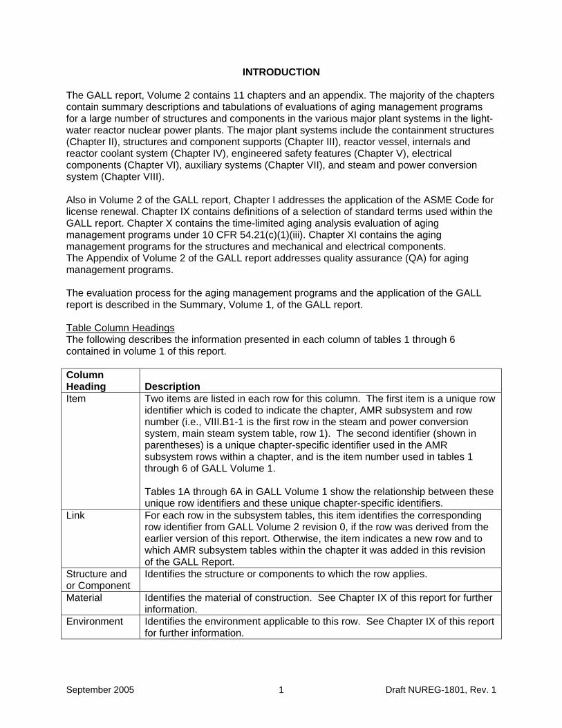
The GALL report, Volume 2 contains 11 chapters and an appendix. The majority of the chapters contain summary descriptions and tabulations of evaluations of aging management programs for a large number of structures and components in the various major plant systems in the light-water reactor nuclear power plants. The major plant systems include the containment structures (Chapter II), structures and component supports (Chapter III), reactor vessel, internals and reactor coolant system (Chapter IV), engineered safety features (Chapter V), electrical components (Chapter VI), auxiliary systems (Chapter VII), and steam and power conversion system (Chapter VIII).
Also in Volume 2 of the GALL report, Chapter I addresses the application of the ASME Code for license renewal. Chapter IX contains definitions of a selection of standard terms used within the GALL report. Chapter X contains the time-limited aging analysis evaluation of aging management programs under 10 CFR 54.21(c)(1)(iii). Chapter XI contains the aging management programs for the structures and mechanical and electrical components. The Appendix of Volume 2 of the GALL report addresses quality assurance (QA) for aging management programs.
The evaluation process for the aging management programs and the application of the GALL report is described in the Summary, Volume 1, of the GALL report.
Table Column Headings The following describes the information presented in each column of tables 1 through 6 contained in volume 1 of this report.
Column Heading Description Item Two items are listed in each row for this column. The first item is a unique row
identifier which is coded to indicate the chapter, AMR subsystem and row number (i.e., VIII.B1-1 is the first row in the steam and power conversion system, main steam system table, row 1). The second identifier (shown in parentheses) is a unique chapter-specific identifier used in the AMR subsystem rows within a chapter, and is the item number used in tables 1 through 6 of GALL Volume 1.
Tables 1A through 6A in GALL Volume 1 show the relationship between these unique row identifiers and these unique chapter-specific identifiers.
Link For each row in the subsystem tables, this item identifies the corresponding row identifier from GALL Volume 2 revision 0, if the row was derived from the earlier version of this report. Otherwise, the item indicates a new row and to which AMR subsystem tables within the chapter it was added in this revision of the GALL Report.
Structure and or Component
Identifies the structure or components to which the row applies.
Material Identifies the material of construction. See Chapter IX of this report for further information.
Environment Identifies the environment applicable to this row. See Chapter IX of this report for further information.
September 2005 1 Draft NUREG-1801, Rev. 1
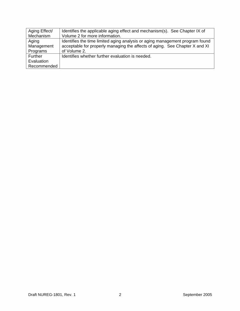
Aging Effect/ Mechanism
Identifies the applicable aging effect and mechanism(s). See Chapter IX of Volume 2 for more information.
Aging Management Programs
Identifies the time limited aging analysis or aging management program found acceptable for properly managing the affects of aging. See Chapter X and XI of Volume 2.
Further Evaluation Recommended
Identifies whether further evaluation is needed.
Draft NUREG-1801, Rev. 1 2 September 2005
CHAPTER I
APPLICATION OF THE ASME CODE
September 2005 I-i Draft NUREG-1801, Rev. 1

This Page Intentionally Left Blank
Draft NUREG-1801, Rev. 1 I-ii September 2005
APPLICATION OF THE ASME CODE
The American Society of Mechanical Engineers (ASME) codes were developed and are revised periodically by industry code committees composed of representatives of utilities, reactor designers, architect-engineers, component manufacturers, insurance companies, the U.S. Nuclear Regulatory Commission (NRC), and others. In 1971, NRC incorporated the ASME Boiler and Pressure Vessel Code into the regulations in 10 CFR 50.55a. [36 FR 11,423 (June 12, 1971)].
The Statements of Consideration (SOC) for the final rule state:
“It has been generally recognized that, for boiling and pressurized water-cooled reactors, pressure vessels, piping, pumps, and valves which are part of the reactor coolant pressure boundary should, as a minimum, be designed, fabricated, inspected, and tested in accordance with the requirements of the applicable American Society of Mechanical Engineers (ASME) codes in effect at the time the equipment is purchased[.]”
The SOC also states:
“Because of the safety significance of uniform early compliance by the nuclear industry with the requirements of these ASME . . . codes and published code revisions, the Commission has adopted the following amendments to Part 50 and 115, which require that certain components and systems of water-cooled reactors important to safety comply with these codes and appropriate revisions to the codes at the earliest feasible time.”
In addition, the SOC states:
“Compliance with the provisions of the amendments and the referenced codes is intended to insure a basic, sound quality level.”
The ASME code, based on the collective engineering judgment of the code committees, documents the conditions that must be monitored, the inspection techniques adequate to observe those conditions, the frequency of the inspections, and the acceptance criteria that the results of the inspections must meet in order to assure the integrity of the structures and components considered in the code. The NRC has adopted this engineering judgment with respect to selected portions of the ASME code, as incorporated in 10 CFR 50.55a.
The NRC has amended 10 CFR 50.55a periodically to incorporate later editions of the ASME code into the regulations, with modifications and limitations, as appropriate. The latest such amendment was in 2001 (including the 2002 and 2003 Addenda). For the purpose of license renewal, the staff has extensively evaluated the appropriate ASME Section XI programs based on the ten program elements described in Volume 1 of this report. Except where noted, the staff has determined that the ASME Section XI programs provide processes for identifying degradation that is attributable to applicable aging effects and are therefore acceptable for managing the effects of aging during the period of extended operation. Where warranted, the NRC staff indicates that certain parts of the code programs should be augmented to satisfy aging management requirements for license renewal.
September 2005 I-1 Draft NUREG-1801, Rev. 1
10 CFR 50.55a is revised periodically to adopt, by reference, new editions, and addenda of the ASME Code. Every 10 years applicants are required to revise the nuclear plant’s ISI program to incorporate the requirements specified in the current version of the 10 CFR 50.55a regulations. NRC SOC associated with the adoption of new editions and addenda of the ASME Code in 10 CFR 50.55a discusses the adequacy of the newer edition and addendum as they relate to the GALL Report. The information contained in these SOCs may provide a reasonable basis for exceptions relating to use of editions or addenda of the ASME Code that are not the same as identified in the GALL Report.
The NRC Director of the Office of Nuclear Reactor Regulation may approve licensee proposed alternatives to the ASME Code in accordance with the provisions of 10 CFR 50.55a(a)(3). These NRC approved ASME Code alternative requirements may have an associated applicability time limit. The applicability time limits associated with the approved alternatives do not extend beyond the current license term. If an applicant seeks relief from specific requirements of 10 CFR 50.55a and Section XI of the ASME Code for the period of extended operation, the applicant will need to re-apply for relief through the 10 CFR 50.55a relief request process once the operating license for the facility has been renewed.
Draft NUREG-1801, Rev. 1 I-2 September 2005
CHAPTER II
CONTAINMENT STRUCTURES
September 2005 II-i Draft NUREG-1801, Rev. 1

This Page Intentionally Left Blank
Draft NUREG-1801, Rev. 1 II-ii September 2005
CONTAINMENT STRUCTURES
A. Pressurized Water Reactor (PWR) Containments
B. Boiling Water Reactor (BWR) Containments
September 2005 II-iii Draft NUREG-1801, Rev. 1

This Page Intentionally Left Blank
Draft NUREG-1801, Rev. 1 II-iv September 2005
PWR CONTAINMENTS
A1. Concrete Containments (Reinforced and Prestressed)
A2. Steel Containments
A3. Common Components
September 2005 II A-1 Draft NUREG-1801, Rev. 1

This Page Intentionally Left Blank
Draft NUREG-1801, Rev. 1 II A-2 September 2005
A1. CONCRETE CONTAINMENTS (REINFORCED AND PRESTRESSED)
Systems, Structures, and Components
This section addresses the elements of pressurized water reactor (PWR) concrete containment structures. Concrete containment structures are divided into three elements: concrete, steel, and prestressing system.
System Interfaces
Functional interfaces include the primary containment heating and ventilation system (VII.F3), containment isolation system (V.C), and containment spray system (V.A). Physical interfaces exist with any structure, system, or component that either penetrates the containment wall, such as the main steam system (VIII.B1) and feedwater system (VIII.D1), or is supported by the containment structure, such as the polar crane (VII.B). The containment structure basemat typically provides support to the nuclear steam supply system (NSSS) components and containment internal structures.
September 2005 II A1-1 Draft NUREG-1801, Rev. 1
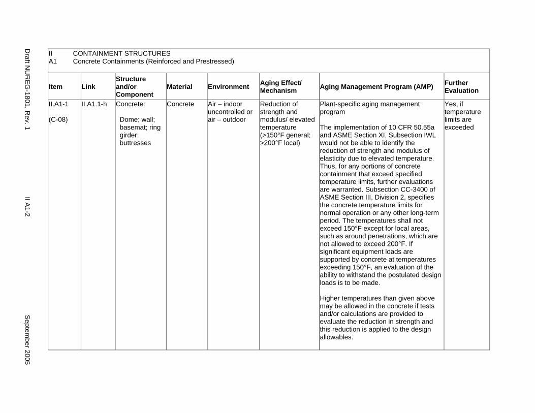
II CONTAINMENT STRUCTURES A1 Concrete Containments (Reinforced and Prestressed)
Item Link Structure and/or Component
Material Environment Aging Effect/ Mechanism Aging Management Program (AMP) Further
Evaluation
II.A1-1
(C-08)
II.A1.1-h Concrete:
Dome; wall; basemat; ring girder; buttresses
Concrete Air – indoor uncontrolled or air – outdoor
Reduction of strength and modulus/ elevated temperature (>150°F general; >200°F local)
Plant-specific aging management program
The implementation of 10 CFR 50.55a and ASME Section XI, Subsection IWL would not be able to identify the reduction of strength and modulus of elasticity due to elevated temperature. Thus, for any portions of concrete containment that exceed specified temperature limits, further evaluations are warranted. Subsection CC-3400 of ASME Section III, Division 2, specifies the concrete temperature limits for normal operation or any other long-term period. The temperatures shall not exceed 150°F except for local areas, such as around penetrations, which are not allowed to exceed 200°F. If significant equipment loads are supported by concrete at temperatures exceeding 150°F, an evaluation of the ability to withstand the postulated design loads is to be made.
Higher temperatures than given above may be allowed in the concrete if tests and/or calculations are provided to evaluate the reduction in strength and this reduction is applied to the design allowables.
Yes, if temperature limits are exceeded
Draft N
UR
EG-1801, R
ev. 1 II A
1-2 S
eptember 2005
II CONTAINMENT STRUCTURES A1 Concrete Containments (Reinforced and Prestressed)
Item Link Structure and/or Component
Material Environment Aging Effect/ Mechanism Aging Management Program (AMP) Further
Evaluation
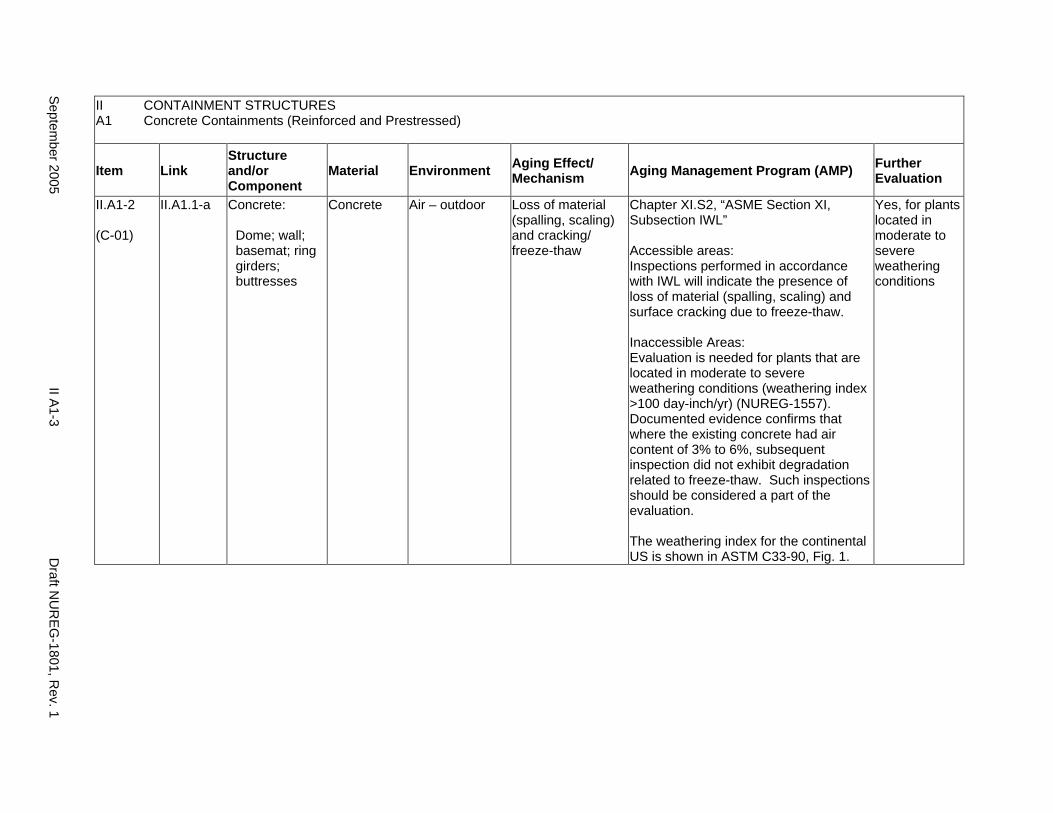
II.A1-2
(C-01)
II.A1.1-a Concrete:
Dome; wall; basemat; ring girders; buttresses
Concrete Air – outdoor Loss of material (spalling, scaling) and cracking/ freeze-thaw
Chapter XI.S2, “ASME Section XI, Subsection IWL”
Accessible areas: Inspections performed in accordance with IWL will indicate the presence of loss of material (spalling, scaling) and surface cracking due to freeze-thaw.
Inaccessible Areas: Evaluation is needed for plants that are located in moderate to severe weathering conditions (weathering index >100 day-inch/yr) (NUREG-1557). Documented evidence confirms that where the existing concrete had air content of 3% to 6%, subsequent inspection did not exhibit degradation related to freeze-thaw. Such inspections should be considered a part of the evaluation.
The weathering index for the continental US is shown in ASTM C33-90, Fig. 1.
Yes, for plants located in moderate to severe weathering conditions
Septem
ber 2005 II A
1-3 D
raft NU
REG
-1801, Rev. 1
II CONTAINMENT STRUCTURES A1 Concrete Containments (Reinforced and Prestressed)
Item Link Structure and/or Component
Material Environment Aging Effect/ Mechanism Aging Management Program (AMP) Further
Evaluation
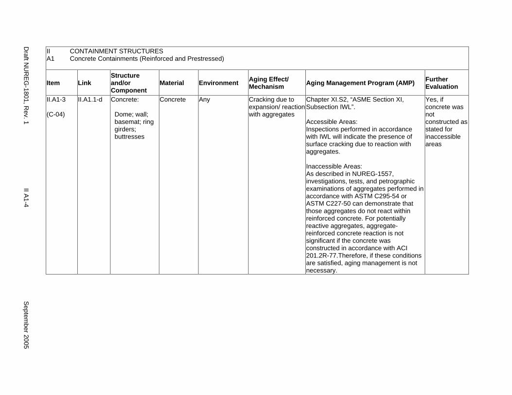
II.A1-3
(C-04)
II.A1.1-d Concrete:
Dome; wall; basemat; ring girders; buttresses
Concrete Any Cracking due to expansion/ reaction with aggregates
Chapter XI.S2, “ASME Section XI, Subsection IWL”.
Accessible Areas: Inspections performed in accordance with IWL will indicate the presence of surface cracking due to reaction with aggregates.
Inaccessible Areas: As described in NUREG-1557, investigations, tests, and petrographic examinations of aggregates performed in accordance with ASTM C295-54 or ASTM C227-50 can demonstrate that those aggregates do not react within reinforced concrete. For potentially reactive aggregates, aggregate-reinforced concrete reaction is not significant if the concrete was constructed in accordance with ACI 201.2R-77.Therefore, if these conditions are satisfied, aging management is not necessary.
Yes, if concrete was not constructed as stated for inaccessible areas
Draft N
UR
EG-1801, R
ev. 1 II A
1-4 S
eptember 2005
II CONTAINMENT STRUCTURES A1 Concrete Containments (Reinforced and Prestressed)
Item Link Structure and/or Component
Material Environment Aging Effect/ Mechanism Aging Management Program (AMP) Further
Evaluation
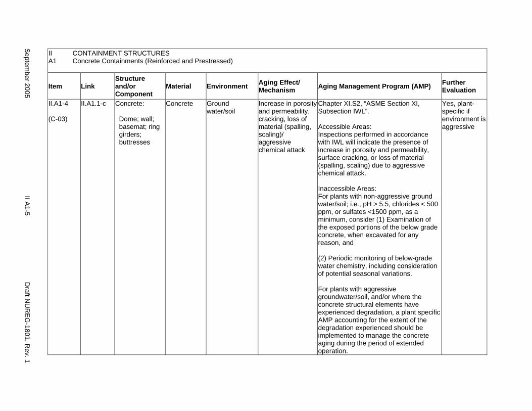
II.A1-4
(C-03)
II.A1.1-c Concrete:
Dome; wall; basemat; ring girders; buttresses
Concrete Ground water/soil
Increase in porosity and permeability, cracking, loss of material (spalling, scaling)/ aggressive chemical attack
Chapter XI.S2, “ASME Section XI, Subsection IWL”.
Accessible Areas: Inspections performed in accordance with IWL will indicate the presence of increase in porosity and permeability, surface cracking, or loss of material (spalling, scaling) due to aggressive chemical attack.
Inaccessible Areas: For plants with non-aggressive ground water/soil; i.e., pH > 5.5, chlorides < 500 ppm, or sulfates <1500 ppm, as a minimum, consider (1) Examination of the exposed portions of the below grade concrete, when excavated for any reason, and
(2) Periodic monitoring of below-grade water chemistry, including consideration of potential seasonal variations.
For plants with aggressive groundwater/soil, and/or where the concrete structural elements have experienced degradation, a plant specific AMP accounting for the extent of the degradation experienced should be implemented to manage the concrete aging during the period of extended operation.
Yes, plant-specific if environment is aggressive
Septem
ber 2005 II A
1-5 D
raft NU
REG
-1801, Rev. 1
II A1
CONTAINMENT STRUCTURES Concrete Containments (Reinforced and Prestressed)
Item Link Structure and/or Component
Material Environment Aging Effect/ Mechanism Aging Management Program (AMP) Further
Evaluation
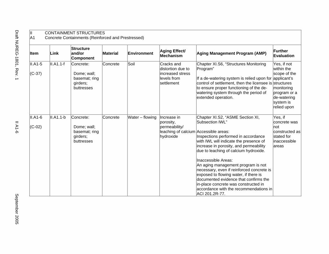
II.A1-5
(C-37)
II.A1.1-f Concrete:
Dome; wall; basemat; ring girders; buttresses
Concrete Soil Cracks and distortion due to increased stress levels from settlement
Chapter XI.S6, “Structures Monitoring Program”
If a de-watering system is relied upon for control of settlement, then the licensee is to ensure proper functioning of the dewatering system through the period of extended operation.
Yes, if not within the scope of the applicant’s structures monitoring program or a de-watering system is relied upon
II.A1-6
(C-02)
II.A1.1-b Concrete:
Dome; wall; basemat; ring girders; buttresses
Concrete Water – flowing Increase in porosity, permeability/ leaching of calcium hydroxide
Chapter XI.S2, “ASME Section XI, Subsection IWL”
Accessible areas: Inspections performed in accordance with IWL will indicate the presence of increase in porosity, and permeability due to leaching of calcium hydroxide.
Inaccessible Areas: An aging management program is not necessary, even if reinforced concrete is exposed to flowing water, if there is documented evidence that confirms the in-place concrete was constructed in accordance with the recommendations in ACI 201.2R-77.
Yes, if concrete was not constructed as stated for inaccessible areas
Draft N
UR
EG-1801, R
ev. 1 II A
1-6 S
eptember 2005
II CONTAINMENT STRUCTURES A1 Concrete Containments (Reinforced and Prestressed)
Item Link Structure and/or Component
Material Environment Aging Effect/ Mechanism Aging Management Program (AMP) Further
Evaluation
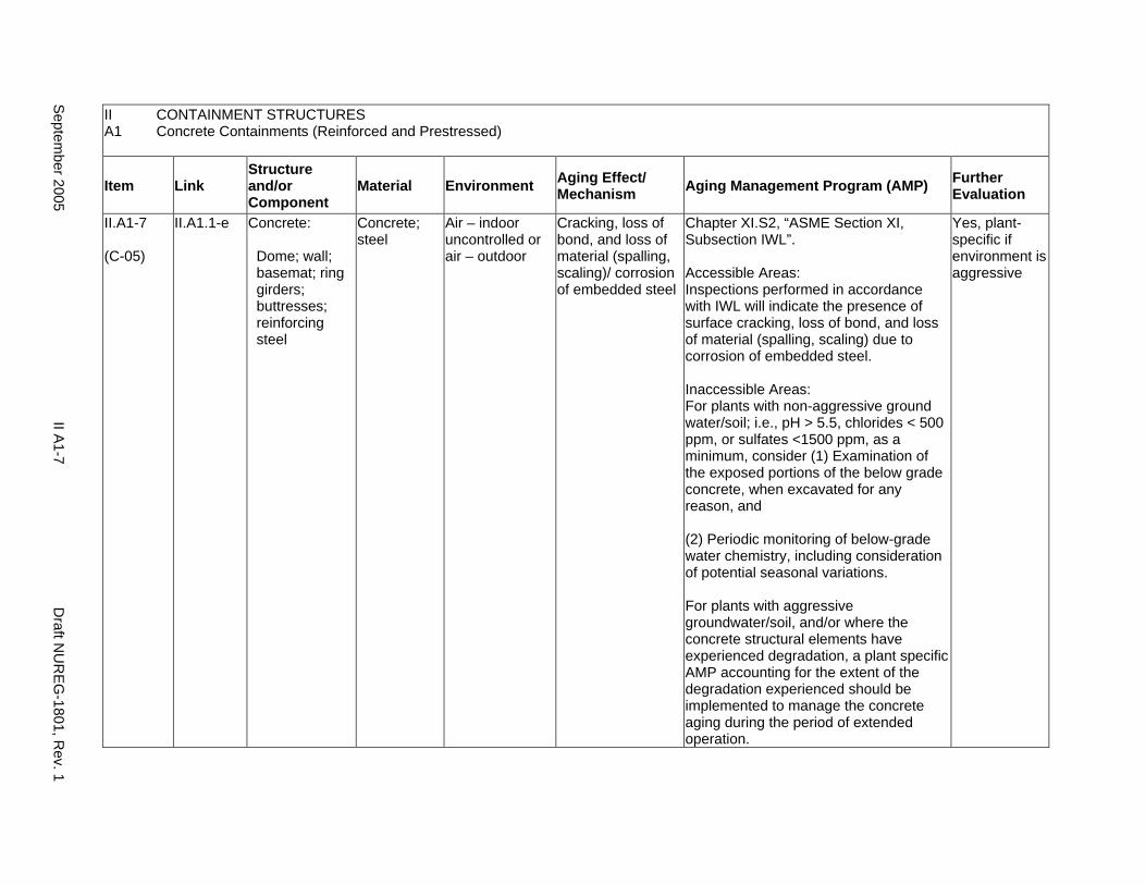
II.A1-7
(C-05)
II.A1.1-e Concrete:
Dome; wall; basemat; ring girders; buttresses; reinforcing steel
Concrete; steel
Air – indoor uncontrolled or air – outdoor
Cracking, loss of bond, and loss of material (spalling, scaling)/ corrosion of embedded steel
Chapter XI.S2, “ASME Section XI, Subsection IWL”.
Accessible Areas: Inspections performed in accordance with IWL will indicate the presence of surface cracking, loss of bond, and loss of material (spalling, scaling) due to corrosion of embedded steel.
Inaccessible Areas: For plants with non-aggressive ground water/soil; i.e., pH > 5.5, chlorides < 500 ppm, or sulfates <1500 ppm, as a minimum, consider (1) Examination of the exposed portions of the below grade concrete, when excavated for any reason, and
(2) Periodic monitoring of below-grade water chemistry, including consideration of potential seasonal variations.
For plants with aggressive groundwater/soil, and/or where the concrete structural elements have experienced degradation, a plant specific AMP accounting for the extent of the degradation experienced should be implemented to manage the concrete aging during the period of extended operation.
Yes, plant-specific if environment is aggressive
Septem
ber 2005 II A
1-7 D
raft NU
REG
-1801, Rev. 1
II A1
CONTAINMENT STRUCTURES Concrete Containments (Reinforced and Prestressed)
Item Link Structure and/or Component
Material Environment Aging Effect/ Mechanism Aging Management Program (AMP) Further
Evaluation
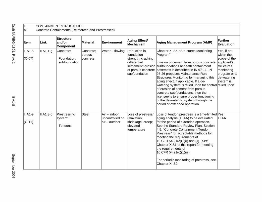
II.A1-8
(C-07)
II.A1.1-g Concrete:
Foundation; subfoundation
Concrete; porous concrete
Water – flowing Reduction in foundation strength, cracking, differential settlement/ erosion of porous concrete subfoundation
Chapter XI.S6, “Structures Monitoring Program”
Erosion of cement from porous concrete subfoundations beneath containment basemats is described in IN 97-11. IN 98-26 proposes Maintenance Rule Structures Monitoring for managing this aging effect, if applicable. If a dewatering system is relied upon for control of erosion of cement from porous concrete subfoundations, then the licensee is to ensure proper functioning of the de-watering system through the period of extended operation.
Yes, if not within the scope of the applicant’s structures monitoring program or a de-watering system is relied upon
II.A1-9
(C-11)
II.A1.3-b Prestressing system:
Tendons
Steel Air – indoor uncontrolled or air – outdoor
Loss of prestress/ relaxation; shrinkage; creep; elevated temperature
Loss of tendon prestress is a time-limited aging analysis (TLAA) to be evaluated for the period of extended operation. See the Standard Review Plan, Section 4.5, “Concrete Containment Tendon Prestress” for acceptable methods for meeting the requirements of 10 CFR 54.21(c)(1)(i) and (ii). See Chapter X.S1 of this report for meeting the requirements of 10 CFR 54.21(c)(1)(iii).
For periodic monitoring of prestress, see Chapter XI.S2.
Yes, TLAA
Draft N
UR
EG-1801, R
ev. 1 II A
1-8 S
eptember 2005
II CONTAINMENT STRUCTURES A1 Concrete Containments (Reinforced and Prestressed)
Item Link Structure and/or Component
Material Environment Aging Effect/ Mechanism Aging Management Program (AMP) Further
Evaluation
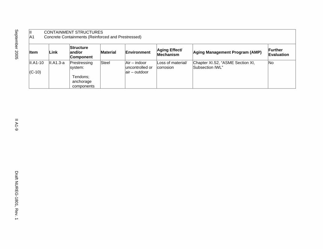
II.A1-10
(C-10)
II.A1.3-a Prestressing system:
Tendons; anchorage components
Steel Air – indoor uncontrolled or air – outdoor
Loss of material/ corrosion
Chapter XI.S2, “ASME Section XI, Subsection IWL”
No
Septem
ber 2005 II A
1-9 D
raft NU
REG
-1801, Rev. 1
II CONTAINMENT STRUCTURES A1 Concrete Containments (Reinforced and Prestressed)
Item Link Structure and/or Component
Material Environment Aging Effect/ Mechanism Aging Management Program (AMP) Further
Evaluation
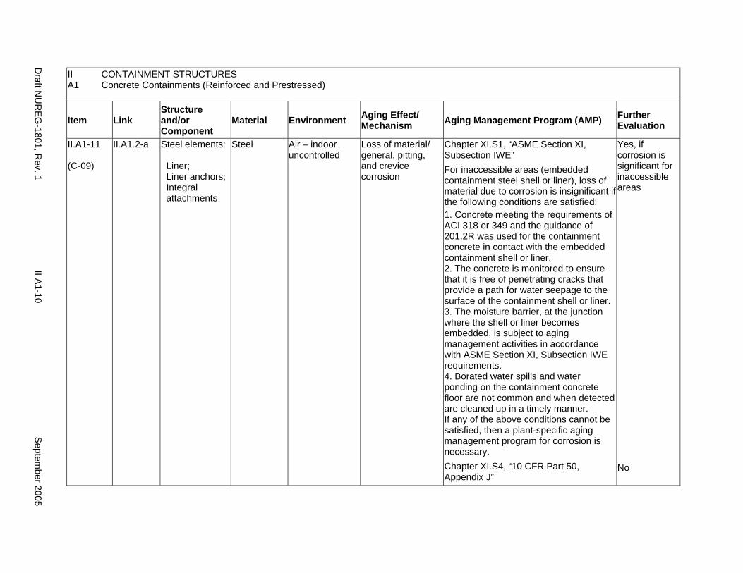
II.A1-11
(C-09)
II.A1.2-a Steel elements:
Liner; Liner anchors; Integral attachments
Steel Air – indoor uncontrolled
Loss of material/ general, pitting, and crevice corrosion
Chapter XI.S1, “ASME Section XI, Subsection IWE” For inaccessible areas (embedded containment steel shell or liner), loss of material due to corrosion is insignificant if the following conditions are satisfied: 1. Concrete meeting the requirements of ACI 318 or 349 and the guidance of 201.2R was used for the containment concrete in contact with the embedded containment shell or liner. 2. The concrete is monitored to ensure that it is free of penetrating cracks that provide a path for water seepage to the surface of the containment shell or liner. 3. The moisture barrier, at the junction where the shell or liner becomes embedded, is subject to aging management activities in accordance with ASME Section XI, Subsection IWE requirements. 4. Borated water spills and water ponding on the containment concrete floor are not common and when detected are cleaned up in a timely manner. If any of the above conditions cannot be satisfied, then a plant-specific aging management program for corrosion is necessary. Chapter XI.S4, “10 CFR Part 50, Appendix J”
Yes, if corrosion is significant for inaccessible areas
No
Draft N
UR
EG-1801, R
ev. 1 II A
1-10 S
eptember 2005
A2. STEEL CONTAINMENTS
Systems, Structures, and Components
This section addresses the elements of pressurized water reactor (PWR) steel containment structures. Steel containment structures are divided into two elements: steel and concrete.
System Interfaces
Functional interfaces include the primary containment heating and ventilation system (VII.F3), containment isolation system (V.C), and containment spray system (V.A). Physical interfaces exist with any structure, system, or component that either penetrates the containment wall, such as the main steam system (VIII.B1) and feedwater system (VIII.D1), or is supported by the containment structure, such as the polar crane (VII.B). The containment structure basemat typically provides support to the nuclear steam supply system (NSSS) components and containment internal structures.
September 2005 II A2-1 Draft NUREG-1801, Rev. 1
II A2
CONTAINMENT STRUCTURES Steel Containments
Item Link Structure and/or Component
Material Environment Aging Effect/ Mechanism Aging Management Program (AMP) Further
Evaluation
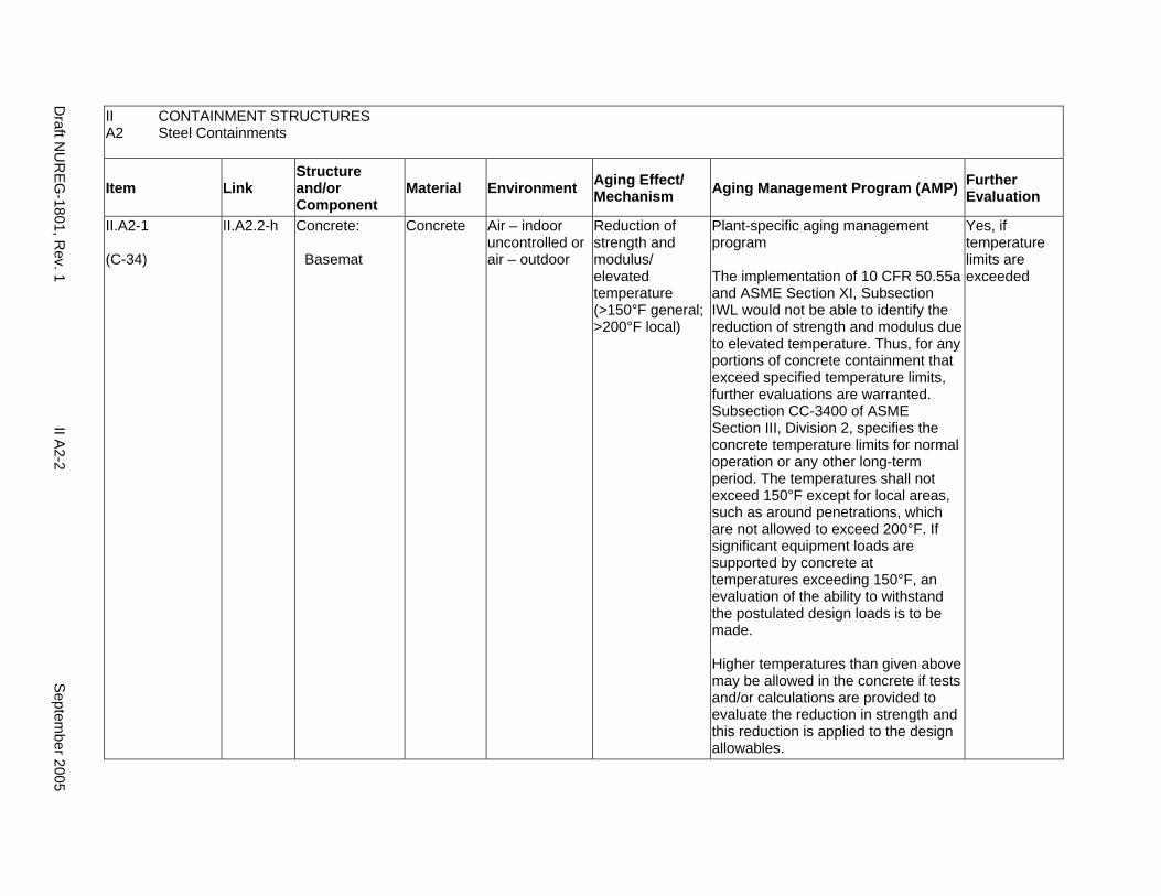
II.A2-1
(C-34)
II.A2.2-h Concrete:
Basemat
Concrete Air – indoor uncontrolled or air – outdoor
Reduction of strength and modulus/ elevated temperature (>150°F general; >200°F local)
Plant-specific aging management program
The implementation of 10 CFR 50.55a and ASME Section XI, Subsection IWL would not be able to identify the reduction of strength and modulus due to elevated temperature. Thus, for any portions of concrete containment that exceed specified temperature limits, further evaluations are warranted. Subsection CC-3400 of ASME Section III, Division 2, specifies the concrete temperature limits for normal operation or any other long-term period. The temperatures shall not exceed 150°F except for local areas, such as around penetrations, which are not allowed to exceed 200°F. If significant equipment loads are supported by concrete at temperatures exceeding 150°F, an evaluation of the ability to withstand the postulated design loads is to be made.
Higher temperatures than given above may be allowed in the concrete if tests and/or calculations are provided to evaluate the reduction in strength and this reduction is applied to the design allowables.
Yes, if temperature limits are exceeded
Draft N
UR
EG-1801, R
ev. 1 II A
2-2 S
eptember 2005
II A2
CONTAINMENT STRUCTURES Steel Containments
Item Link Structure and/or Component
Material Environment Aging Effect/ Mechanism Aging Management Program (AMP) Further
Evaluation
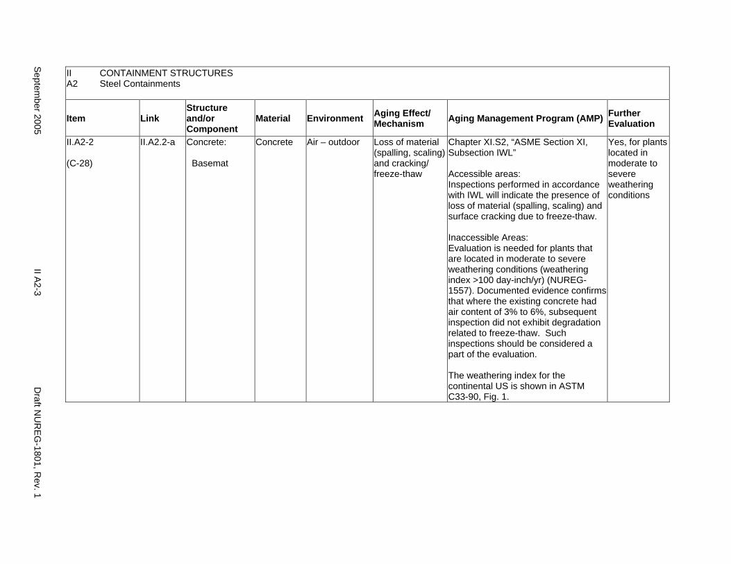
II.A2-2
(C-28)
II.A2.2-a Concrete:
Basemat
Concrete Air – outdoor Loss of material (spalling, scaling) and cracking/ freeze-thaw
Chapter XI.S2, “ASME Section XI, Subsection IWL”
Accessible areas: Inspections performed in accordance with IWL will indicate the presence of loss of material (spalling, scaling) and surface cracking due to freeze-thaw.
Inaccessible Areas: Evaluation is needed for plants that are located in moderate to severe weathering conditions (weathering index >100 day-inch/yr) (NUREG1557). Documented evidence confirms that where the existing concrete had air content of 3% to 6%, subsequent inspection did not exhibit degradation related to freeze-thaw. Such inspections should be considered a part of the evaluation.
The weathering index for the continental US is shown in ASTM C33-90, Fig. 1.
Yes, for plants located in moderate to severe weathering conditions
Septem
ber 2005 II A
2-3 D
raft NU
REG
-1801, Rev. 1

II CONTAINMENT STRUCTURES A2 Steel Containments
Item Link Structure and/or Component
Material Environment Aging Effect/ Mechanism Aging Management Program (AMP) Further
Evaluation
II.A2-3
(C-38)
II.A2.2-d Concrete:
Basemat
Concrete Any Cracking due to expansion/ reaction with aggregates
Chapter XI.S2, “ASME Section XI, Subsection IWL”.
Accessible Areas: Inspections performed in accordance with IWL will indicate the presence of surface cracking due to reaction with aggregates.
Inaccessible Areas: As described in NUREG-1557, investigations, tests, and petrographic examinations of aggregates performed in accordance with ASTM C295-54 or ASTM C227-50 can demonstrate that those aggregates do not react within reinforced concrete. For potentially reactive aggregates, aggregate-reinforced concrete reaction is not significant if the concrete was constructed in accordance with ACI 201.2R-77.Therefore, if these conditions are satisfied, aging management is not necessary.
Yes, if concrete was not constructed as stated for inaccessible areas
Draft N
UR
EG-1801, R
ev. 1 II A
2-4 S
eptember 2005

II A2
CONTAINMENT STRUCTURES Steel Containments
Item Link Structure and/or Component
Material Environment Aging Effect/ Mechanism Aging Management Program (AMP) Further
Evaluation
II.A2-4
(C-25)
II.A2.2-c Concrete:
Basemat
Concrete Ground water/soil
Increase in porosity and permeability, cracking, loss of material (spalling, scaling)/ aggressive chemical attack
Chapter XI.S2, “ASME Section XI, Subsection IWL”.
Accessible Areas: Inspections performed in accordance with IWL will indicate the presence of increase in porosity and permeability, surface cracking, or loss of material (spalling, scaling) due to aggressive chemical attack.
Inaccessible Areas: For plants with non-aggressive ground water/soil; i.e., pH > 5.5, chlorides < 500 ppm, or sulfates <1500 ppm, as a minimum, consider (1) Examination of the exposed portions of the below grade concrete, when excavated for any reason, and
(2) Periodic monitoring of below-grade water chemistry, including consideration of potential seasonal variations.
For plants with aggressive groundwater/soil, and/or where the concrete structural elements have experienced degradation, a plant specific AMP accounting for the extent of the degradation experienced should be implemented to manage the concrete aging during the period of extended operation.
Yes, plant-specific if environment is aggressive
Septem
ber 2005 II A
2-5 D
raft NU
REG
-1801, Rev. 1
II A2
CONTAINMENT STRUCTURES Steel Containments
Item Link Structure and/or Component
Material Environment Aging Effect/ Mechanism Aging Management Program (AMP) Further
Evaluation
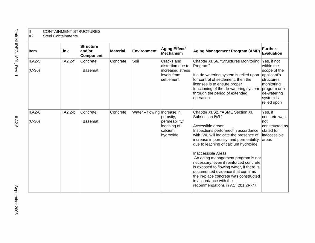
II.A2-5
(C-36)
II.A2.2-f Concrete:
Basemat
Concrete Soil Cracks and distortion due to increased stress levels from settlement
Chapter XI.S6, “Structures Monitoring Program”
If a de-watering system is relied upon for control of settlement, then the licensee is to ensure proper functioning of the de-watering system through the period of extended operation.
Yes, if not within the scope of the applicant’s structures monitoring program or a de-watering system is relied upon
II.A2-6
(C-30)
II.A2.2-b Concrete:
Basemat
Concrete Water – flowing Increase in porosity, permeability/ leaching of calcium hydroxide
Chapter XI.S2, “ASME Section XI, Subsection IWL”
Accessible areas: Inspections performed in accordance with IWL will indicate the presence of increase in porosity, and permeability due to leaching of calcium hydroxide.
Inaccessible Areas: An aging management program is not necessary, even if reinforced concrete is exposed to flowing water, if there is documented evidence that confirms the in-place concrete was constructed in accordance with the recommendations in ACI 201.2R-77.
Yes, if concrete was not constructed as stated for inaccessible areas
Draft N
UR
EG-1801, R
ev. 1 II A
2-6 S
eptember 2005

II CONTAINMENT STRUCTURES A2 Steel Containments
Item Link Structure and/or Component
Material Environment Aging Effect/ Mechanism Aging Management Program (AMP) Further
Evaluation
II.A2-7
(C-43)
II.A2.2-e Concrete:
Basemat; reinforcing steel
Concrete; steel
Air – indoor uncontrolled or air – outdoor
Cracking, loss of bond, and loss of material (spalling, scaling)/ corrosion of embedded steel
Chapter XI.S2, “ASME Section XI, Subsection IWL”.
Accessible Areas: Inspections performed in accordance with IWL will indicate the presence of surface cracking, loss of bond, and loss of material (spalling, scaling) due to corrosion of embedded steel.
Inaccessible Areas: For plants with non-aggressive ground water/soil; i.e., pH > 5.5, chlorides < 500 ppm, or sulfates <1500 ppm, as a minimum, consider (1) Examination of the exposed portions of the below grade concrete, when excavated for any reason, and (2) Periodic monitoring of below-grade water chemistry, including consideration of potential seasonal variations. For plants with aggressive groundwater/soil, and/or where the concrete structural elements have experienced degradation, a plant specific AMP accounting for the extent of the degradation experienced should be implemented to manage the concrete aging during the period of extended operation.
Yes, plant-specific if environment is aggressive
Septem
ber 2005 II A
2-7 D
raft NU
REG
-1801, Rev. 1
II A2
CONTAINMENT STRUCTURES Steel Containments
Item Link Structure and/or Component
Material Environment Aging Effect/ Mechanism Aging Management Program (AMP) Further
Evaluation
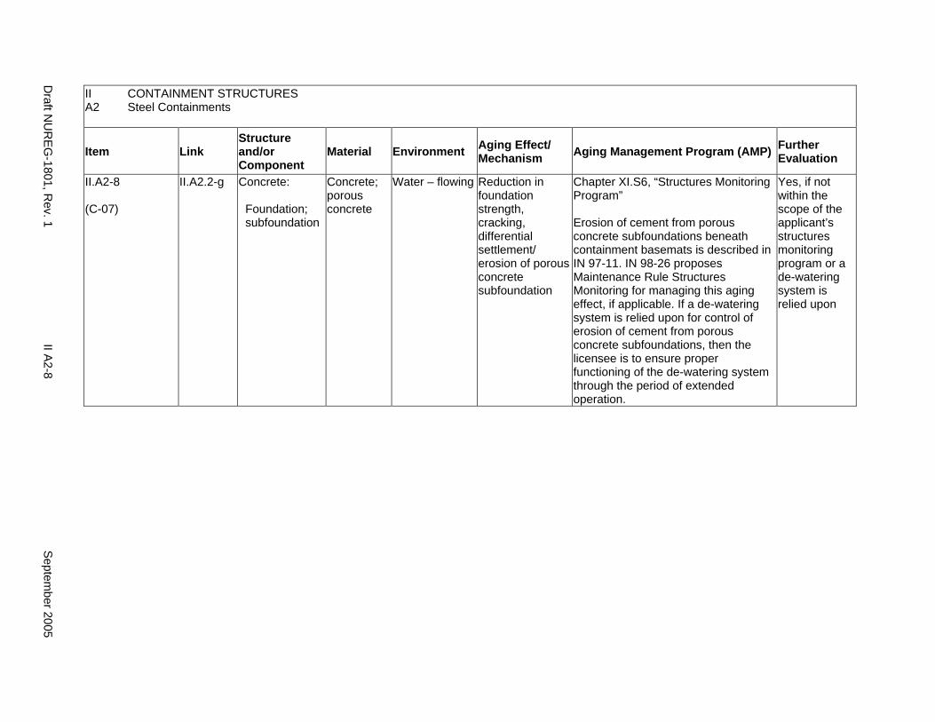
II.A2-8
(C-07)
II.A2.2-g Concrete:
Foundation; subfoundation
Concrete; porous concrete
Water – flowing Reduction in foundation strength, cracking, differential settlement/ erosion of porous concrete subfoundation
Chapter XI.S6, “Structures Monitoring Program”
Erosion of cement from porous concrete subfoundations beneath containment basemats is described in IN 97-11. IN 98-26 proposes Maintenance Rule Structures Monitoring for managing this aging effect, if applicable. If a de-watering system is relied upon for control of erosion of cement from porous concrete subfoundations, then the licensee is to ensure proper functioning of the de-watering system through the period of extended operation.
Yes, if not within the scope of the applicant’s structures monitoring program or a de-watering system is relied upon
Draft N
UR
EG-1801, R
ev. 1 II A
2-8 S
eptember 2005
II A2
CONTAINMENT STRUCTURES Steel Containments
Item Link Structure and/or Component
Material Environment Aging Effect/ Mechanism Aging Management Program (AMP) Further
Evaluation
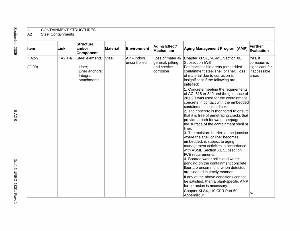
II.A2-9
(C-09)
II.A2.1-a Steel elements:
Liner; Liner anchors; Integral attachments
Steel Air – indoor uncontrolled
Loss of material/ general, pitting, and crevice corrosion
Chapter XI.S1, “ASME Section XI, Subsection IWE” For inaccessible areas (embedded containment steel shell or liner), loss of material due to corrosion is insignificant if the following are satisfied: 1. Concrete meeting the requirements of ACI 318 or 349 and the guidance of 201.2R was used for the containment concrete in contact with the embedded containment shell or liner. 2. The concrete is monitored to ensure that it is free of penetrating cracks that provide a path for water seepage to the surface of the containment shell or liner. 3. The moisture barrier, at the junction where the shell or liner becomes embedded, is subject to aging management activities in accordance with ASME Section XI, Subsection IWE requirements. 4. Borated water spills and water ponding on the containment concrete floor are uncommon, when detected are cleaned in timely manner. If any of the above conditions cannot be satisfied, then a plant-specific AMP for corrosion is necessary. Chapter XI.S4, “10 CFR Part 50, Appendix J”
Yes, if corrosion is significant for inaccessible areas
No
Septem
ber 2005 II A
2-9 D
raft NU
REG
-1801, Rev. 1
This Page Intentionally Left Blank
Draft N
UR
EG-1801, R
ev. 1 II A
2-10 S
eptember 2005
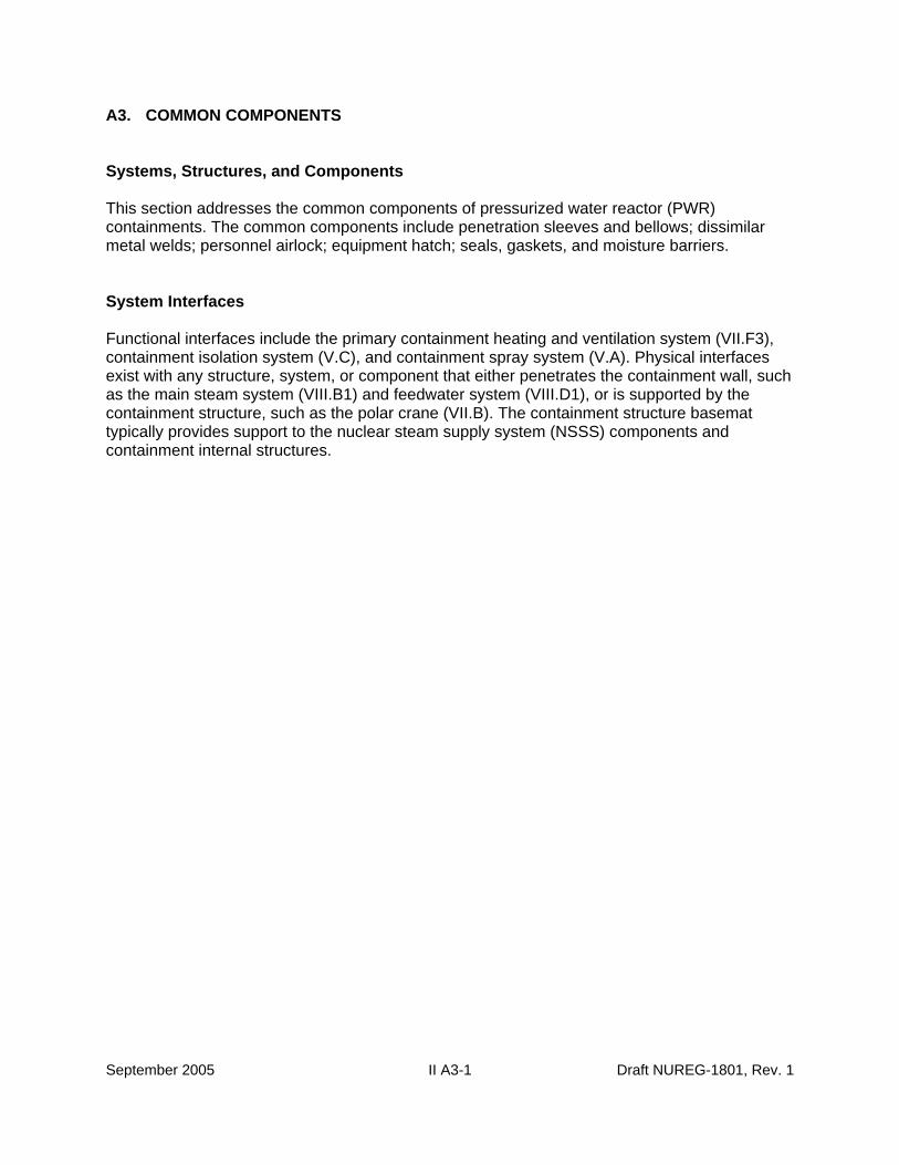
A3. COMMON COMPONENTS
Systems, Structures, and Components
This section addresses the common components of pressurized water reactor (PWR) containments. The common components include penetration sleeves and bellows; dissimilar metal welds; personnel airlock; equipment hatch; seals, gaskets, and moisture barriers.
System Interfaces
Functional interfaces include the primary containment heating and ventilation system (VII.F3), containment isolation system (V.C), and containment spray system (V.A). Physical interfaces exist with any structure, system, or component that either penetrates the containment wall, such as the main steam system (VIII.B1) and feedwater system (VIII.D1), or is supported by the containment structure, such as the polar crane (VII.B). The containment structure basemat typically provides support to the nuclear steam supply system (NSSS) components and containment internal structures.
September 2005 II A3-1 Draft NUREG-1801, Rev. 1
II A3
CONTAINMENT STRUCTURES Common Components
Item Link Structure and/or Component
Material Environment Aging Effect/ Mechanism Aging Management Program (AMP) Further
Evaluation
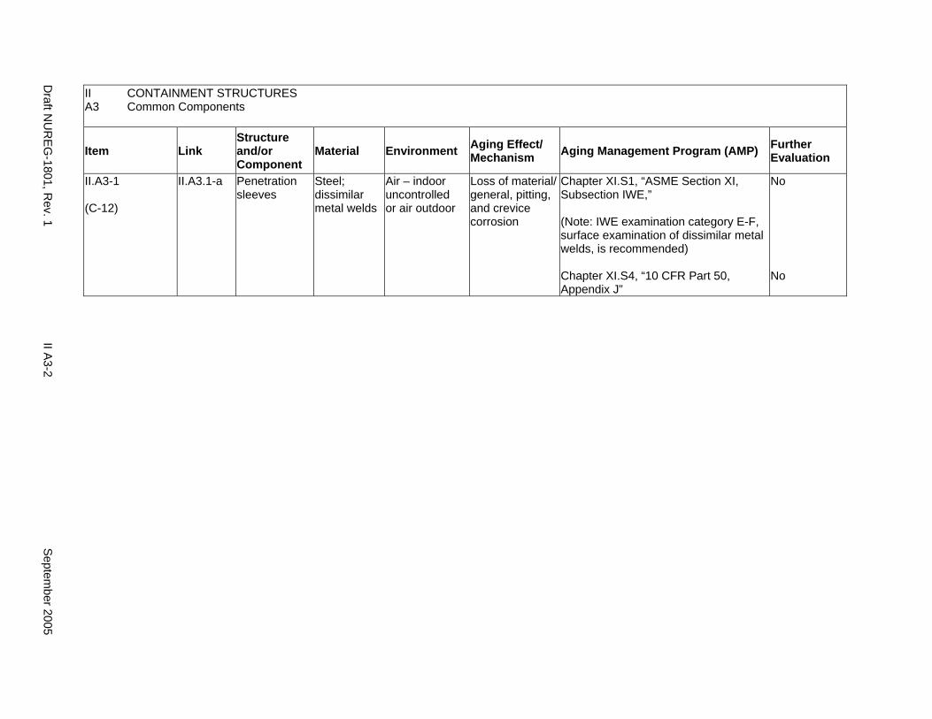
II.A3-1
(C-12)
II.A3.1-a Penetration sleeves
Steel; dissimilar metal welds
Air – indoor uncontrolled or air outdoor
Loss of material/ general, pitting, and crevice corrosion
Chapter XI.S1, “ASME Section XI, Subsection IWE,”
(Note: IWE examination category E-F, surface examination of dissimilar metal welds, is recommended)
Chapter XI.S4, “10 CFR Part 50, Appendix J”
No
No
Draft N
UR
EG-1801, R
ev. 1 II A
3-2 S
eptember 2005

II A3
CONTAINMENT STRUCTURES Common Components
Item Link Structure and/or Component
Material Environment Aging Effect/ Mechanism Aging Management Program (AMP) Further
Evaluation
II.A3-2
(C-15)
II.A3.1-d Penetration sleeves; Penetration bellows
Stainless steel; dissimilar metal welds
Air – indoor uncontrolled or air – outdoor
Cracking/ stress corrosion cracking
Chapter XI.S1, “ASME Section XI, Subsection IWE” and Chapter XI.S4, “10 CFR Part 50, Appendix J”
Evaluation of 10 CFR 50.55a/ASME Section XI, Subsection IWE is augmented as follows:
(4) Detection of Aging Effects: Transgranular Stress corrosion cracking (TGSCC) is a concern for dissimilar metal welds. In the case of bellows assemblies, SCC may cause aging effects particularly if the material is not shielded from a corrosive environment. ASME Section XI, Subsection IWE covers inspection of these items under examination categories E-B, E-F, and E-P (10 CFR Part 50, Appendix J pressure tests). 10 CFR 50.55a identifies examination categories E-B and E-F as optional during the current term of operation. For the extended period of operation, Examination Categories E-B & E-F, and additional appropriate examinations to detect SCC in bellows assemblies and dissimilar metal welds are warranted to address this issue.
(10) Operating Experience: IN 92-20 describes an instance of containment bellows cracking, resulting in loss of leak tightness.
Yes, detection of aging effects is to be evaluated
Septem
ber 2005 II A
3-3 D
raft NU
REG
-1801, Rev.1

II A3
CONTAINMENT STRUCTURES Common Components
Item Link Structure and/or Component
Material Environment Aging Effect/ Mechanism Aging Management Program (AMP) Further
Evaluation
II.A3-3
(C-14)
II.A3.1-c Penetration sleeves; Penetration bellows
Steel; stainless steel; dissimilar metal welds
Air – indoor uncontrolled or air – outdoor
Cracking/ cyclic loading
(CLB fatigue analysis does not exist)
Chapter XI.S1, “ASME Section XI, Subsection IWE ” and Chapter XI.S4, “10 CFR Part 50, Appendix J”
Evaluation of 10 CFR 50.55a/ASME Section XI, Subsection IWE is to be supplemented to consider the following: (4) Detection of Aging Effects: VT-3 visual inspection may not detect fine cracks.
Yes, detection of aging effects is to be evaluated
II.A3-4
(C-13)
II.A3.1-b Penetration sleeves; Penetration bellows
Steel; stainless steel; dissimilar metal welds
Air – indoor uncontrolled or air – outdoor
Cumulative fatigue damage/ fatigue
(Only if CLB fatigue analysis exists)
Fatigue is a time-limited aging analysis (TLAA) to be evaluated for the period of extended operation. See the Standard Review Plan, Section 4.6, “Containment Liner Plate and Penetration Fatigue Analysis” for acceptable methods for meeting the requirements of 10 CFR 54.21(c)(1).
Yes, TLAA
II.A3-5
(C-17)
II.A3.2-b Personnel airlock, equipment hatch, CRD hatch:
Locks, hinges, and closure mechanisms
Steel Air – indoor uncontrolled or air outdoor
Loss of leak tightness/ mechanical wear of locks, hinges and closure mechanisms
Chapter XI.S4, “10 CFR Part 50, Appendix J” and
Plant Technical Specifications
No
Draft N
UR
EG-1801, R
ev. 1 II A
3-4 S
eptember 2005

II CONTAINMENT STRUCTURES A3 Common Components
Item Link Structure and/or Component
Material Environment Aging Effect/ Mechanism Aging Management Program (AMP) Further
Evaluation
II.A3-6
(C-16)
II.A3.2-a Personnel airlock, equipment hatch, CRD hatch
Steel Air – indoor uncontrolled or air – outdoor
Loss of material/ general, pitting, and crevice corrosion
Chapter XI.S1, “ASME Section XI, Subsection IWE,”
Chapter XI.S4, “10 CFR Part 50, Appendix J”
No
No
II.A3-7
(C-18)
II.A3.3-a Seals, gaskets, and moisture barriers (caulking, flashing, and other sealants)
Elastomers, rubber and other similar materials
Air – indoor uncontrolled or air – outdoor
Loss of sealing; Leakage through containment/ deterioration of seals, gaskets, and moisture barriers (caulking, flashing, and other sealants)
Chapter XI.S1, “ASME Section XI, Subsection IWE”
Leak tightness will be monitored by 10 CFR Part 50, Appendix J Leak Rate Tests for pressure boundary, seals and gaskets (including O-rings).
No
Septem
ber 2005 II A
3-5 D
raft NU
REG
-1801, Rev.1

This Page Intentionally Left Blank
Draft NUREG-1801, Rev. 1 II A3-6 September 2005
BWR CONTAINMENTS
B1. Mark I Containments
B2. Mark II Containments
B3. Mark III Containments
B4. Common Components
September 2005 II B-i Draft NUREG-1801, Rev. 1

This Page Intentionally Left Blank
Draft NUREG-1801, Rev. 1 II B-ii September 2005
B1. MARK I CONTAINMENTS
Systems, Structures, and Components
This section addresses the elements of boiling water reactor (BWR) Mark I containment structures. Steel containments are discussed in II.B1.1 and concrete containments are discussed in II.B.2.
System Interfaces
Functional interfaces include the primary containment heating and ventilation system (VII.F3), containment isolation system (V.C), and standby gas treatment system (V.B). Physical interfaces exist with any structure, system, or component that either penetrates the containment wall, such as the main steam system (VIII.B2) and feedwater system (VIII.D2), or is supported by the containment structure. The containment structure basemat may provide support to the NSSS components and containment internal structures.
September 2005 II B1-1 Draft NUREG-1801, Rev. 1
II CONTAINMENT STRUCTURES B1.1 Mark I Steel Containments
Item Link Structure and/or Component
Material Environment Aging Effect/ Mechanism Aging Management Program (AMP) Further
Evaluation
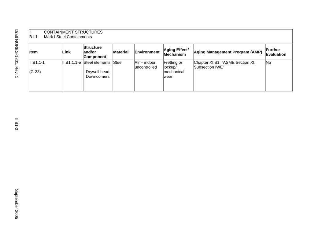
II.B1.1-1
(C-23)
II.B1.1.1-e Steel elements:
Drywell head; Downcomers
Steel Air – indoor uncontrolled
Fretting or lockup/ mechanical wear
Chapter XI.S1, “ASME Section XI, Subsection IWE”
No
Draft N
UR
EG-1801, R
ev. 1 II B
1-2 S
eptember 2005
II CONTAINMENT STRUCTURES B1.1 Mark I Steel Containments
Item Link Structure and/or Component
Material Environment Aging Effect/ Mechanism Aging Management Program (AMP) Further
Evaluation
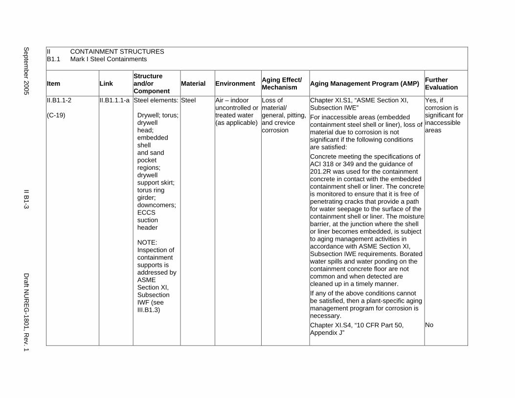
II.B1.1-2
(C-19)
II.B1.1.1-a Steel elements:
Drywell; torus; drywell head; embedded shell and sand pocket regions; drywell support skirt; torus ring girder; downcomers; ECCS suction header
NOTE: Inspection of containment supports is addressed by ASME Section XI, Subsection IWF (see III.B1.3)
Steel Air – indoor uncontrolled or treated water (as applicable)
Loss of material/ general, pitting, and crevice corrosion
Chapter XI.S1, “ASME Section XI, Subsection IWE” For inaccessible areas (embedded containment steel shell or liner), loss of material due to corrosion is not significant if the following conditions are satisfied: Concrete meeting the specifications of ACI 318 or 349 and the guidance of 201.2R was used for the containment concrete in contact with the embedded containment shell or liner. The concrete is monitored to ensure that it is free of penetrating cracks that provide a path for water seepage to the surface of the containment shell or liner. The moisture barrier, at the junction where the shell or liner becomes embedded, is subject to aging management activities in accordance with ASME Section XI, Subsection IWE requirements. Borated water spills and water ponding on the containment concrete floor are not common and when detected are cleaned up in a timely manner. If any of the above conditions cannot be satisfied, then a plant-specific aging management program for corrosion is necessary. Chapter XI.S4, “10 CFR Part 50, Appendix J”
Yes, if corrosion is significant for inaccessible areas
No
Septem
ber 2005 II B
1-3 D
raft NU
REG
-1801, Rev. 1
II CONTAINMENT STRUCTURES B1.1 Mark I Steel Containments
Item Link Structure and/or Component
Material Environment Aging Effect/ Mechanism Aging Management Program (AMP) Further
Evaluation
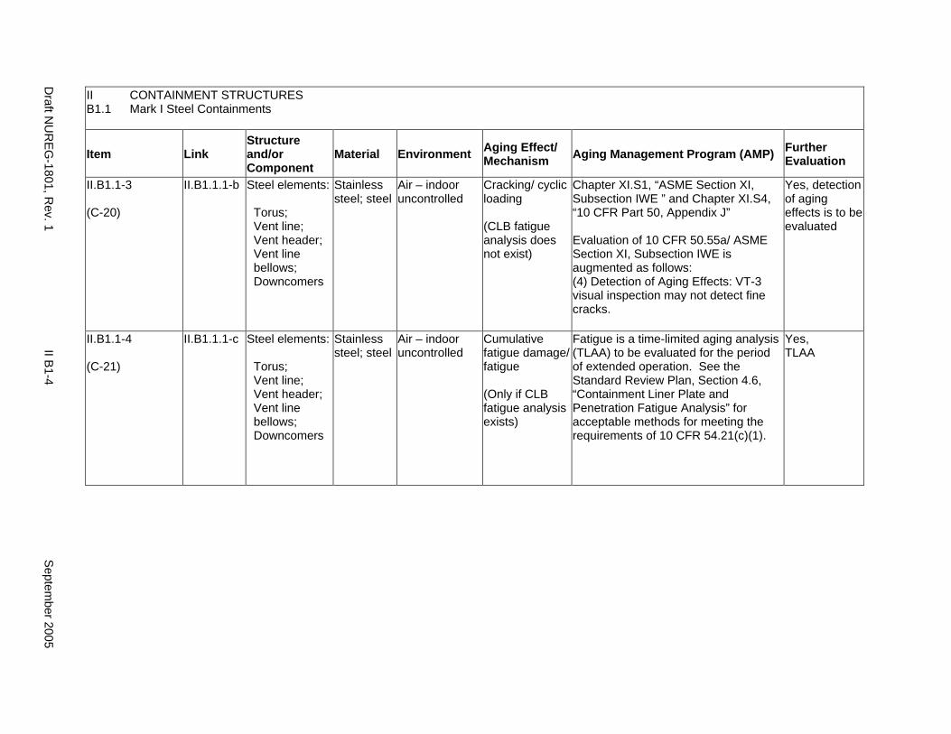
II.B1.1-3
(C-20)
II.B1.1.1-b Steel elements:
Torus; Vent line; Vent header; Vent line bellows; Downcomers
Stainless steel; steel
Air – indoor uncontrolled
Cracking/ cyclic loading
(CLB fatigue analysis does not exist)
Chapter XI.S1, “ASME Section XI, Subsection IWE ” and Chapter XI.S4, “10 CFR Part 50, Appendix J”
Evaluation of 10 CFR 50.55a/ ASME Section XI, Subsection IWE is augmented as follows: (4) Detection of Aging Effects: VT-3 visual inspection may not detect fine cracks.
Yes, detection of aging effects is to be evaluated
II.B1.1-4
(C-21)
II.B1.1.1-c Steel elements:
Torus; Vent line; Vent header; Vent line bellows; Downcomers
Stainless steel; steel
Air – indoor uncontrolled
Cumulative fatigue damage/ fatigue
(Only if CLB fatigue analysis exists)
Fatigue is a time-limited aging analysis (TLAA) to be evaluated for the period of extended operation. See the Standard Review Plan, Section 4.6, “Containment Liner Plate and Penetration Fatigue Analysis” for acceptable methods for meeting the requirements of 10 CFR 54.21(c)(1).
Yes, TLAA
Draft N
UR
EG-1801, R
ev. 1 II B
1-4 S
eptember 2005
II CONTAINMENT STRUCTURES B1.1 Mark I Steel Containments
Item Link Structure and/or Component
Material Environment Aging Effect/ Mechanism Aging Management Program (AMP) Further
Evaluation
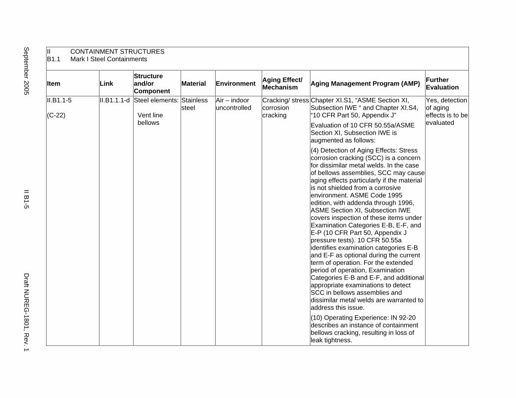
II.B1.1-5
(C-22)
II.B1.1.1-d Steel elements:
Vent line bellows
Stainless steel
Air – indoor uncontrolled
Cracking/ stress corrosion cracking
Chapter XI.S1, “ASME Section XI, Subsection IWE “ and Chapter XI.S4, “10 CFR Part 50, Appendix J” Evaluation of 10 CFR 50.55a/ASME Section XI, Subsection IWE is augmented as follows: (4) Detection of Aging Effects: Stress corrosion cracking (SCC) is a concern for dissimilar metal welds. In the case of bellows assemblies, SCC may cause aging effects particularly if the material is not shielded from a corrosive environment. ASME Code 1995 edition, with addenda through 1996, ASME Section XI, Subsection IWE covers inspection of these items under Examination Categories E-B, E-F, and E-P (10 CFR Part 50, Appendix J pressure tests). 10 CFR 50.55a identifies examination categories E-B and E-F as optional during the current term of operation. For the extended period of operation, Examination Categories E-B and E-F, and additional appropriate examinations to detect SCC in bellows assemblies and dissimilar metal welds are warranted to address this issue. (10) Operating Experience: IN 92-20 describes an instance of containment bellows cracking, resulting in loss of leak tightness.
Yes, detection of aging effects is to be evaluated
Septem
ber 2005 II B
1-5 D
raft NU
REG
-1801, Rev. 1
II CONTAINMENT STRUCTURES B1.2 Mark I Concrete Containments
Item Link Structure and/or Component
Material Environment Aging Effect/ Mechanism Aging Management Program (AMP) Further
Evaluation
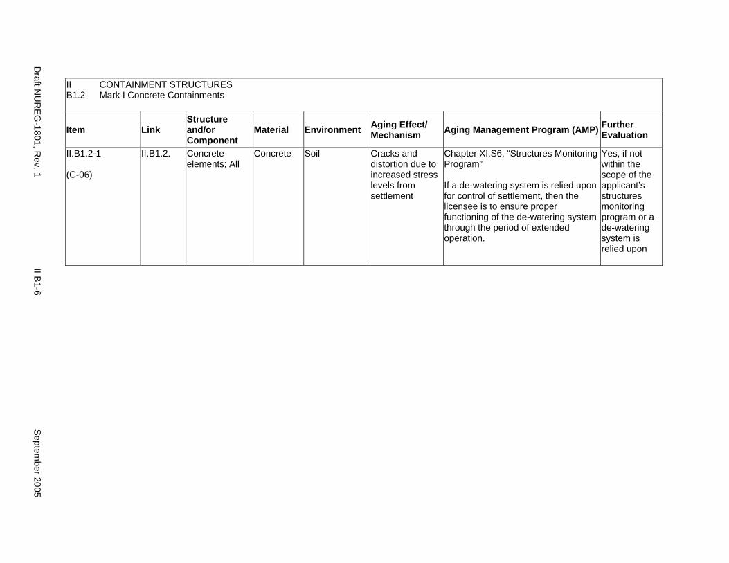
II.B1.2-1
(C-06)
II.B1.2. Concrete elements; All
Concrete Soil Cracks and distortion due to increased stress levels from settlement
Chapter XI.S6, “Structures Monitoring Program”
If a de-watering system is relied upon for control of settlement, then the licensee is to ensure proper functioning of the de-watering system through the period of extended operation.
Yes, if not within the scope of the applicant’s structures monitoring program or a de-watering system is relied upon
Draft N
UR
EG-1801, R
ev. 1 II B
1-6 S
eptember 2005

II CONTAINMENT STRUCTURES B1.2 Mark I Concrete Containments
Item Link Structure and/or Component
Material Environment Aging Effect/ Mechanism Aging Management Program (AMP) Further
Evaluation
II.B1.2-2
(C-41)
II.B1.2. Concrete:
Basemat; reinforcing steel
Concrete; steel
Air – indoor uncontrolled or air – outdoor
Cracking, loss of bond, and loss of material (spalling, scaling)/ corrosion of embedded steel
Chapter XI.S2, “ASME Section XI, Subsection IWL”.
Accessible Areas: Inspections performed in accordance with IWL will indicate the presence of surface cracking, loss of bond, and loss of material (spalling, scaling) due to corrosion of embedded steel.
Inaccessible Areas: For plants with non-aggressive ground water/soil; i.e., pH > 5.5, chlorides < 500 ppm, or sulfates <1500 ppm, as a minimum, consider (1) Examination of the exposed portions of the below grade concrete, when excavated for any reason, and
(2) Periodic monitoring of below-grade water chemistry, including consideration of potential seasonal variations.
For plants with aggressive groundwater/soil, and/or where the concrete structural elements have experienced degradation, a plant specific AMP accounting for the extent of the degradation experienced should be implemented to manage the concrete aging during the period of extended operation.
Yes, plant-specific if environment is aggressive
Septem
ber 2005 II B
1-7 D
raft NU
REG
-1801, Rev. 1
II CONTAINMENT STRUCTURES B1.2 Mark I Concrete Containments
Item Link Structure and/or Component
Material Environment Aging Effect/ Mechanism Aging Management Program (AMP) Further
Evaluation
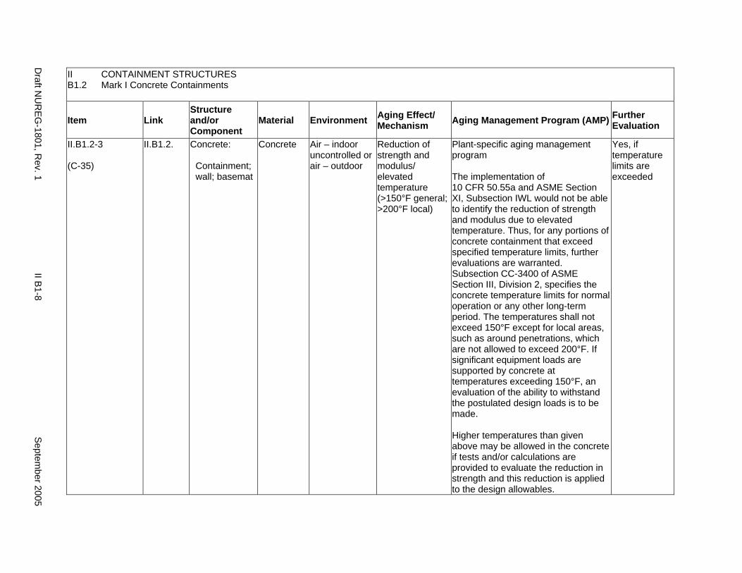
II.B1.2-3
(C-35)
II.B1.2. Concrete:
Containment; wall; basemat
Concrete Air – indoor uncontrolled or air – outdoor
Reduction of strength and modulus/ elevated temperature (>150°F general; >200°F local)
Plant-specific aging management program
The implementation of 10 CFR 50.55a and ASME Section XI, Subsection IWL would not be able to identify the reduction of strength and modulus due to elevated temperature. Thus, for any portions of concrete containment that exceed specified temperature limits, further evaluations are warranted. Subsection CC-3400 of ASME Section III, Division 2, specifies the concrete temperature limits for normal operation or any other long-term period. The temperatures shall not exceed 150°F except for local areas, such as around penetrations, which are not allowed to exceed 200°F. If significant equipment loads are supported by concrete at temperatures exceeding 150°F, an evaluation of the ability to withstand the postulated design loads is to be made.
Higher temperatures than given above may be allowed in the concrete if tests and/or calculations are provided to evaluate the reduction in strength and this reduction is applied to the design allowables.
Yes, if temperature limits are exceeded
Draft N
UR
EG-1801, R
ev. 1 II B
1-8 S
eptember 2005

II CONTAINMENT STRUCTURES B1.2 Mark I Concrete Containments
Item Link Structure and/or Component
Material Environment Aging Effect/ Mechanism Aging Management Program (AMP) Further
Evaluation
II.B1.2-4
(C-39)
II.B1.2. Concrete:
Containment; wall; basemat
Concrete Any Cracking due to expansion/ reaction with aggregates
Chapter XI.S2, “ASME Section XI, Subsection IWL”.
Accessible Areas: Inspections performed in accordance with IWL will indicate the presence of surface cracking due to reaction with aggregates.
Inaccessible Areas: As described in NUREG-1557, investigations, tests, and petrographic examinations of aggregates performed in accordance with ASTM C295-54 or ASTM C227-50 can demonstrate that those aggregates do not react within reinforced concrete. For potentially reactive aggregates, aggregate-reinforced concrete reaction is not significant if the concrete was constructed in accordance with ACI 201.2R-77. Therefore, if these conditions are satisfied, aging management is not necessary.
Yes, if concrete was not constructed as stated for inaccessible areas
Septem
ber 2005 II B
1-9 D
raft NU
REG
-1801, Rev. 1
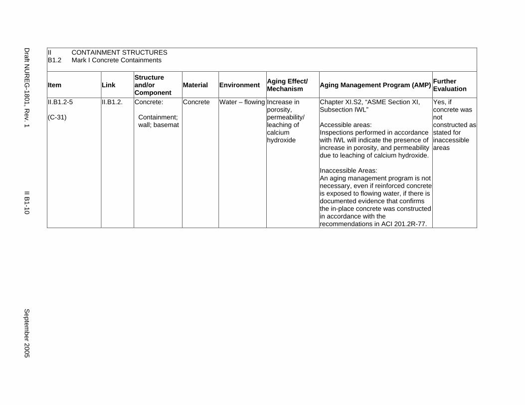
II CONTAINMENT STRUCTURES B1.2 Mark I Concrete Containments
Item Link Structure and/or Component
Material Environment Aging Effect/ Mechanism Aging Management Program (AMP) Further
Evaluation
II.B1.2-5
(C-31)
II.B1.2. Concrete:
Containment; wall; basemat
Concrete Water – flowing Increase in porosity, permeability/ leaching of calcium hydroxide
Chapter XI.S2, “ASME Section XI, Subsection IWL”
Accessible areas: Inspections performed in accordance with IWL will indicate the presence of increase in porosity, and permeability due to leaching of calcium hydroxide.
Inaccessible Areas: An aging management program is not necessary, even if reinforced concrete is exposed to flowing water, if there is documented evidence that confirms the in-place concrete was constructed in accordance with the recommendations in ACI 201.2R-77.
Yes, if concrete was not constructed as stated for inaccessible areas
Draft N
UR
EG-1801, R
ev. 1 II B
1-10 S
eptember 2005

II CONTAINMENT STRUCTURES B1.2 Mark I Concrete Containments
Item Link Structure and/or Component
Material Environment Aging Effect/ Mechanism Aging Management Program (AMP) Further
Evaluation
II.B1.2-6
(C-07)
II.B1.2. Concrete:
Foundation; subfoundation
Concrete; porous concrete
Water – flowing Reduction in foundation strength, cracking, differential settlement/ erosion of porous concrete subfoundation
Chapter XI.S6, “Structures Monitoring Program”
Erosion of cement from porous concrete subfoundations beneath containment basemats is described in IN 97-11. IN 98-26 proposes Maintenance Rule Structures Monitoring for managing this aging effect, if applicable. If a de-watering system is relied upon for control of erosion of cement from porous concrete subfoundations, then the licensee is to ensure proper functioning of the de-watering system through the period of extended operation.
Yes, if not within the scope of the applicant’s structures monitoring program or a de-watering system is relied upon
Septem
ber 2005 II B
1-11 D
raft NU
REG
-1801, Rev. 1
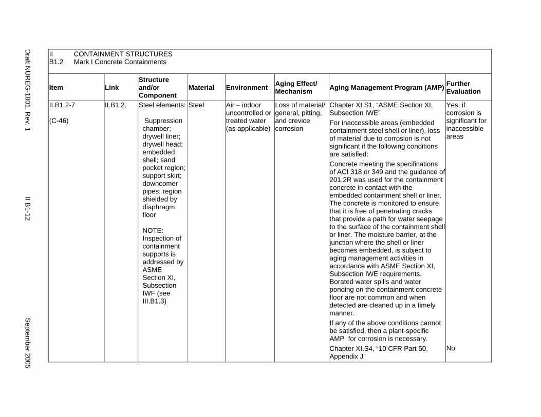
II CONTAINMENT STRUCTURES B1.2 Mark I Concrete Containments
Item Link Structure and/or Component
Material Environment Aging Effect/ Mechanism Aging Management Program (AMP) Further
Evaluation
II.B1.2-7
(C-46)
II.B1.2. Steel elements:
Suppression chamber; drywell liner; drywell head; embedded shell; sand pocket region; support skirt; downcomer pipes; region shielded by diaphragm floor
NOTE: Inspection of containment supports is addressed by ASME Section XI, Subsection IWF (see III.B1.3)
Steel Air – indoor uncontrolled or treated water (as applicable)
Loss of material/ general, pitting, and crevice corrosion
Chapter XI.S1, “ASME Section XI, Subsection IWE” For inaccessible areas (embedded containment steel shell or liner), loss of material due to corrosion is not significant if the following conditions are satisfied: Concrete meeting the specifications of ACI 318 or 349 and the guidance of 201.2R was used for the containment concrete in contact with the embedded containment shell or liner. The concrete is monitored to ensure that it is free of penetrating cracks that provide a path for water seepage to the surface of the containment shell or liner. The moisture barrier, at the junction where the shell or liner becomes embedded, is subject to aging management activities in accordance with ASME Section XI, Subsection IWE requirements. Borated water spills and water ponding on the containment concrete floor are not common and when detected are cleaned up in a timely manner. If any of the above conditions cannot be satisfied, then a plant-specific AMP for corrosion is necessary. Chapter XI.S4, “10 CFR Part 50, Appendix J”
Yes, if corrosion is significant for inaccessible areas
No
Draft N
UR
EG-1801, R
ev. 1 II B
1-12 S
eptember 2005
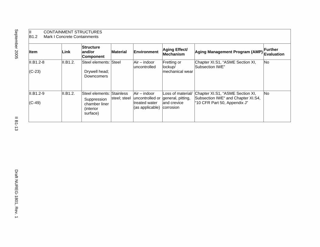
II CONTAINMENT STRUCTURES B1.2 Mark I Concrete Containments
Item Link Structure and/or Component
Material Environment Aging Effect/ Mechanism Aging Management Program (AMP) Further
Evaluation
II.B1.2-8
(C-23)
II.B1.2. Steel elements:
Drywell head; Downcomers
Steel Air – indoor uncontrolled
Fretting or lockup/ mechanical wear
Chapter XI.S1, “ASME Section XI, Subsection IWE”
No
II.B1.2-9
(C-49)
II.B1.2. Steel elements: Suppression chamber liner (interior surface)
Stainless steel; steel
Air – indoor uncontrolled or treated water (as applicable)
Loss of material/ general, pitting, and crevice corrosion
Chapter XI.S1, “ASME Section XI, Subsection IWE“ and Chapter XI.S4, “10 CFR Part 50, Appendix J"
No
Septem
ber 2005 II B
1-13 D
raft NU
REG
-1801, Rev. 1

This Page Intentionally Left Blank
Draft N
UR
EG-1801, R
ev. 1 II B
1-14 S
eptember 2005
B2. MARK II CONTAINMENTS
Systems, Structures, and Components
This section addresses the elements of boiling water reactor (BWR) Mark II containment structures. Mark II steel containments are discussed in II.B2.1. Mark II concrete containments are discussed in II.B2.2.
System Interfaces
Functional interfaces include the primary containment heating and ventilation system (VII.F3), containment isolation system (V.C), and standby gas treatment system (V.B). Physical interfaces exist with any structure, system, or component that either penetrates the containment wall, such as the main steam system (VIII.B2) and feedwater system (VIII.D2), or is supported by the containment structure. The containment structure basemat may provide support to the NSSS components and containment internal structures.
September 2005 II B2-1 Draft NUREG-1801, Rev. 1
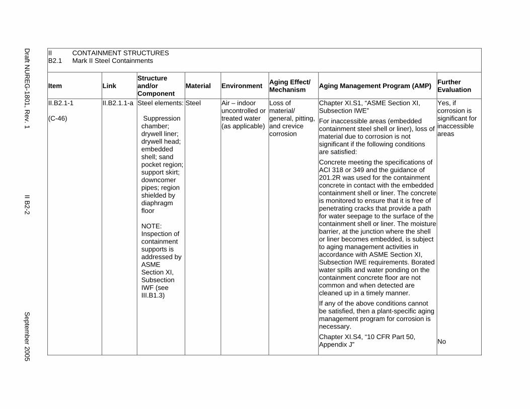
II CONTAINMENT STRUCTURES B2.1 Mark II Steel Containments
Item Link Structure and/or Component
Material Environment Aging Effect/ Mechanism Aging Management Program (AMP) Further
Evaluation
II.B2.1-1
(C-46)
II.B2.1.1-a Steel elements:
Suppression chamber; drywell liner; drywell head; embedded shell; sand pocket region; support skirt; downcomer pipes; region shielded by diaphragm floor
NOTE: Inspection of containment supports is addressed by ASME Section XI, Subsection IWF (see III.B1.3)
Steel Air – indoor uncontrolled or treated water (as applicable)
Loss of material/ general, pitting, and crevice corrosion
Chapter XI.S1, “ASME Section XI, Subsection IWE” For inaccessible areas (embedded containment steel shell or liner), loss of material due to corrosion is not significant if the following conditions are satisfied: Concrete meeting the specifications of ACI 318 or 349 and the guidance of 201.2R was used for the containment concrete in contact with the embedded containment shell or liner. The concrete is monitored to ensure that it is free of penetrating cracks that provide a path for water seepage to the surface of the containment shell or liner. The moisture barrier, at the junction where the shell or liner becomes embedded, is subject to aging management activities in accordance with ASME Section XI, Subsection IWE requirements. Borated water spills and water ponding on the containment concrete floor are not common and when detected are cleaned up in a timely manner. If any of the above conditions cannot be satisfied, then a plant-specific aging management program for corrosion is necessary. Chapter XI.S4, “10 CFR Part 50, Appendix J”
Yes, if corrosion is significant for inaccessible areas
No
Draft N
UR
EG-1801, R
ev. 1 II B
2-2 S
eptember 2005
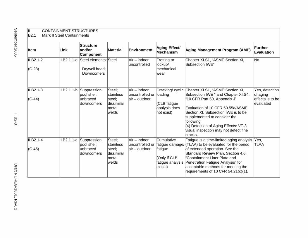
II CONTAINMENT STRUCTURES B2.1 Mark II Steel Containments
Item Link Structure and/or Component
Material Environment Aging Effect/ Mechanism Aging Management Program (AMP) Further
Evaluation
II.B2.1-2
(C-23)
II.B2.1.1-d Steel elements:
Drywell head; Downcomers
Steel Air – indoor uncontrolled
Fretting or lockup/ mechanical wear
Chapter XI.S1, “ASME Section XI, Subsection IWE”
No
II.B2.1-3
(C-44)
II.B2.1.1-b Suppression pool shell; unbraced downcomers
Steel; stainless steel; dissimilar metal welds
Air – indoor uncontrolled or air – outdoor
Cracking/ cyclic loading
(CLB fatigue analysis does not exist)
Chapter XI.S1, “ASME Section XI, Subsection IWE ” and Chapter XI.S4, “10 CFR Part 50, Appendix J”
Evaluation of 10 CFR 50.55a/ASME Section XI, Subsection IWE is to be supplemented to consider the following: (4) Detection of Aging Effects: VT-3 visual inspection may not detect fine cracks.
Yes, detection of aging effects is to be evaluated
II.B2.1-4
(C-45)
II.B2.1.1-c Suppression pool shell; unbraced downcomers
Steel; stainless steel; dissimilar metal welds
Air – indoor uncontrolled or air – outdoor
Cumulative fatigue damage/ fatigue
(Only if CLB fatigue analysis exists)
Fatigue is a time-limited aging analysis (TLAA) to be evaluated for the period of extended operation. See the Standard Review Plan, Section 4.6, “Containment Liner Plate and Penetration Fatigue Analysis” for acceptable methods for meeting the requirements of 10 CFR 54.21(c)(1).
Yes, TLAA
Septem
ber 2005 II B
2-3 D
raft NU
REG
-1801, Rev. 1
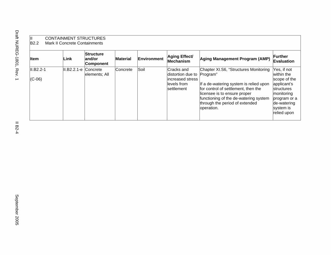
II CONTAINMENT STRUCTURES B2.2 Mark II Concrete Containments
Item Link Structure and/or Component
Material Environment Aging Effect/ Mechanism Aging Management Program (AMP) Further
Evaluation
II.B2.2-1
(C-06)
II.B2.2.1-e Concrete elements; All
Concrete Soil Cracks and distortion due to increased stress levels from settlement
Chapter XI.S6, “Structures Monitoring Program”
If a de-watering system is relied upon for control of settlement, then the licensee is to ensure proper functioning of the de-watering system through the period of extended operation.
Yes, if not within the scope of the applicant’s structures monitoring program or a de-watering system is relied upon
Draft N
UR
EG-1801, R
ev. 1 II B
2-4 S
eptember 2005
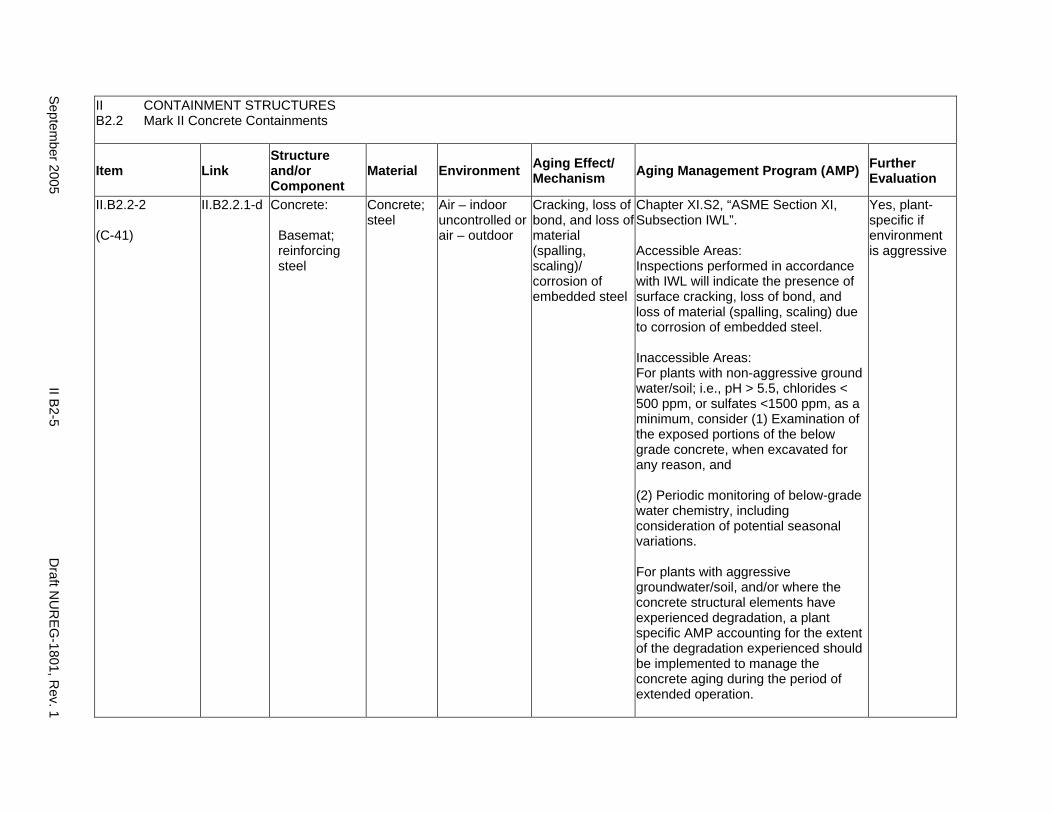
II CONTAINMENT STRUCTURES B2.2 Mark II Concrete Containments
Item Link Structure and/or Component
Material Environment Aging Effect/ Mechanism Aging Management Program (AMP) Further
Evaluation
II.B2.2-2
(C-41)
II.B2.2.1-d Concrete:
Basemat; reinforcing steel
Concrete; steel
Air – indoor uncontrolled or air – outdoor
Cracking, loss of bond, and loss of material (spalling, scaling)/ corrosion of embedded steel
Chapter XI.S2, “ASME Section XI, Subsection IWL”.
Accessible Areas: Inspections performed in accordance with IWL will indicate the presence of surface cracking, loss of bond, and loss of material (spalling, scaling) due to corrosion of embedded steel.
Inaccessible Areas: For plants with non-aggressive ground water/soil; i.e., pH > 5.5, chlorides < 500 ppm, or sulfates <1500 ppm, as a minimum, consider (1) Examination of the exposed portions of the below grade concrete, when excavated for any reason, and
(2) Periodic monitoring of below-grade water chemistry, including consideration of potential seasonal variations.
For plants with aggressive groundwater/soil, and/or where the concrete structural elements have experienced degradation, a plant specific AMP accounting for the extent of the degradation experienced should be implemented to manage the concrete aging during the period of extended operation.
Yes, plant-specific if environment is aggressive
Septem
ber 2005 II B
2-5 D
raft NU
REG
-1801, Rev. 1
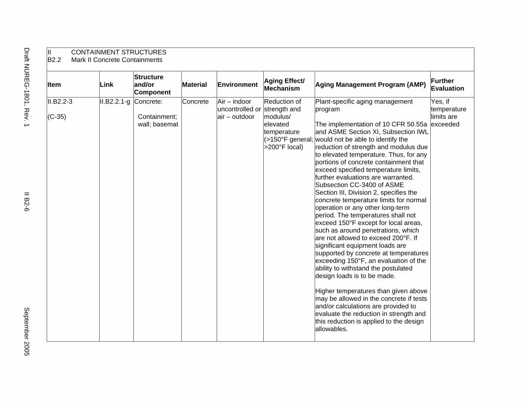
II CONTAINMENT STRUCTURES B2.2 Mark II Concrete Containments
Item Link Structure and/or Component
Material Environment Aging Effect/ Mechanism Aging Management Program (AMP) Further
Evaluation
II.B2.2-3
(C-35)
II.B2.2.1-g Concrete:
Containment; wall; basemat
Concrete Air – indoor uncontrolled or air – outdoor
Reduction of strength and modulus/ elevated temperature (>150°F general; >200°F local)
Plant-specific aging management program
The implementation of 10 CFR 50.55a and ASME Section XI, Subsection IWL would not be able to identify the reduction of strength and modulus due to elevated temperature. Thus, for any portions of concrete containment that exceed specified temperature limits, further evaluations are warranted. Subsection CC-3400 of ASME Section III, Division 2, specifies the concrete temperature limits for normal operation or any other long-term period. The temperatures shall not exceed 150°F except for local areas, such as around penetrations, which are not allowed to exceed 200°F. If significant equipment loads are supported by concrete at temperatures exceeding 150°F, an evaluation of the ability to withstand the postulated design loads is to be made.
Higher temperatures than given above may be allowed in the concrete if tests and/or calculations are provided to evaluate the reduction in strength and this reduction is applied to the design allowables.
Yes, if temperature limits are exceeded
Draft N
UR
EG-1801, R
ev. 1 II B
2-6 S
eptember 2005

II CONTAINMENT STRUCTURES B2.2 Mark II Concrete Containments
Item Link Structure and/or Component
Material Environment Aging Effect/ Mechanism Aging Management Program (AMP) Further
Evaluation
II.B2.2-4
(C-39)
II.B2.2.1-c Concrete:
Containment; wall; basemat
Concrete Any Cracking due to expansion/ reaction with aggregates
Chapter XI.S2, “ASME Section XI, Subsection IWL”.
Accessible Areas: Inspections performed in accordance with IWL will indicate the presence of surface cracking due to reaction with aggregates.
Inaccessible Areas: As described in NUREG-1557, investigations, tests, and petrographic examinations of aggregates performed in accordance with ASTM C295-54 or ASTM C227-50 can demonstrate that those aggregates do not react within reinforced concrete. For potentially reactive aggregates, aggregate-reinforced concrete reaction is not significant if the concrete was constructed in accordance with ACI 201.2R-77. Therefore, if these conditions are satisfied, aging management is not necessary.
Yes, if concrete was not constructed as stated for inaccessible areas
Septem
ber 2005 II B
2-7 D
raft NU
REG
-1801, Rev. 1
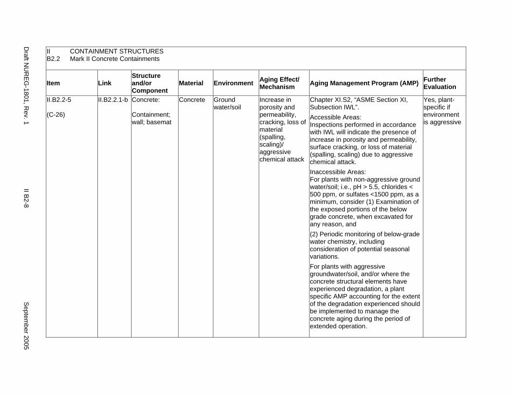
II CONTAINMENT STRUCTURES B2.2 Mark II Concrete Containments
Item Link Structure and/or Component
Material Environment Aging Effect/ Mechanism Aging Management Program (AMP) Further
Evaluation
II.B2.2-5
(C-26)
II.B2.2.1-b Concrete:
Containment; wall; basemat
Concrete Ground water/soil
Increase in porosity and permeability, cracking, loss of material (spalling, scaling)/ aggressive chemical attack
Chapter XI.S2, “ASME Section XI, Subsection IWL”. Accessible Areas: Inspections performed in accordance with IWL will indicate the presence of increase in porosity and permeability, surface cracking, or loss of material (spalling, scaling) due to aggressive chemical attack. Inaccessible Areas: For plants with non-aggressive ground water/soil; i.e., pH > 5.5, chlorides < 500 ppm, or sulfates <1500 ppm, as a minimum, consider (1) Examination of the exposed portions of the below grade concrete, when excavated for any reason, and (2) Periodic monitoring of below-grade water chemistry, including consideration of potential seasonal variations. For plants with aggressive groundwater/soil, and/or where the concrete structural elements have experienced degradation, a plant specific AMP accounting for the extent of the degradation experienced should be implemented to manage the concrete aging during the period of extended operation.
Yes, plant-specific if environment is aggressive
Draft N
UR
EG-1801, R
ev. 1 II B
2-8 S
eptember 2005
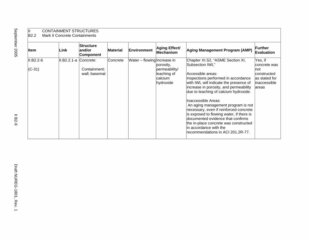
II CONTAINMENT STRUCTURES B2.2 Mark II Concrete Containments
Item Link Structure and/or Component
Material Environment Aging Effect/ Mechanism Aging Management Program (AMP) Further
Evaluation
II.B2.2-6
(C-31)
II.B2.2.1-a Concrete:
Containment; wall; basemat
Concrete Water – flowing Increase in porosity, permeability/ leaching of calcium hydroxide
Chapter XI.S2, “ASME Section XI, Subsection IWL”
Accessible areas: Inspections performed in accordance with IWL will indicate the presence of increase in porosity, and permeability due to leaching of calcium hydroxide.
Inaccessible Areas: An aging management program is not necessary, even if reinforced concrete is exposed to flowing water, if there is documented evidence that confirms the in-place concrete was constructed in accordance with the recommendations in ACI 201.2R-77.
Yes, if concrete was not constructed as stated for inaccessible areas
Septem
ber 2005 II B
2-9 D
raft NU
REG
-1801, Rev. 1
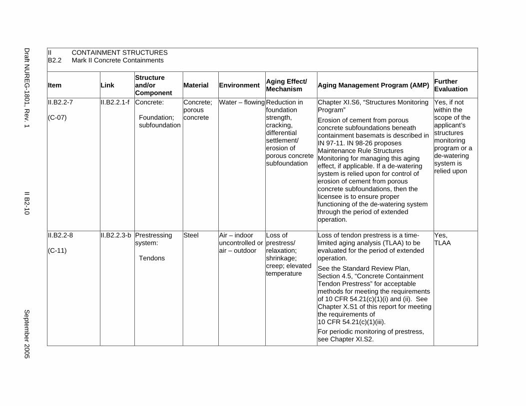
II CONTAINMENT STRUCTURES B2.2 Mark II Concrete Containments
Item Link Structure and/or Component
Material Environment Aging Effect/ Mechanism Aging Management Program (AMP) Further
Evaluation
II.B2.2-7
(C-07)
II.B2.2.1-f Concrete:
Foundation; subfoundation
Concrete; porous concrete
Water – flowing Reduction in foundation strength, cracking, differential settlement/ erosion of porous concrete subfoundation
Chapter XI.S6, “Structures Monitoring Program” Erosion of cement from porous concrete subfoundations beneath containment basemats is described in IN 97-11. IN 98-26 proposes Maintenance Rule Structures Monitoring for managing this aging effect, if applicable. If a de-watering system is relied upon for control of erosion of cement from porous concrete subfoundations, then the licensee is to ensure proper functioning of the de-watering system through the period of extended operation.
Yes, if not within the scope of the applicant’s structures monitoring program or a de-watering system is relied upon
II.B2.2-8
(C-11)
II.B2.2.3-b Prestressing system:
Tendons
Steel Air – indoor uncontrolled or air – outdoor
Loss of prestress/ relaxation; shrinkage; creep; elevated temperature
Loss of tendon prestress is a time-limited aging analysis (TLAA) to be evaluated for the period of extended operation. See the Standard Review Plan, Section 4.5, “Concrete Containment Tendon Prestress” for acceptable methods for meeting the requirements of 10 CFR 54.21(c)(1)(i) and (ii). See Chapter X.S1 of this report for meeting the requirements of 10 CFR 54.21(c)(1)(iii). For periodic monitoring of prestress, see Chapter XI.S2.
Yes, TLAA
Draft N
UR
EG-1801, R
ev. 1 II B
2-10 S
eptember 2005
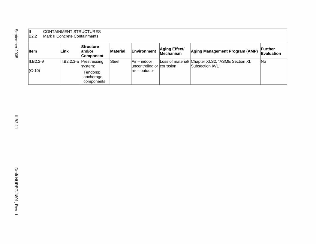
II CONTAINMENT STRUCTURES B2.2 Mark II Concrete Containments
Item Link Structure and/or Component
Material Environment Aging Effect/ Mechanism Aging Management Program (AMP) Further
Evaluation
II.B2.2-9
(C-10)
II.B2.2.3-a Prestressing system:
Tendons; anchorage components
Steel Air – indoor uncontrolled or air – outdoor
Loss of material/ corrosion
Chapter XI.S2, “ASME Section XI, Subsection IWL”
No
Septem
ber 2005 II B
2-11 D
raft NU
REG
-1801, Rev. 1
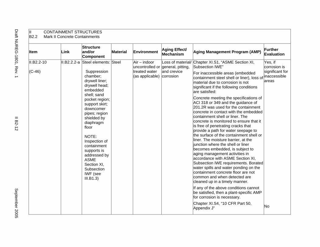
II CONTAINMENT STRUCTURES B2.2 Mark II Concrete Containments
Item Link Structure and/or Component
Material Environment Aging Effect/ Mechanism Aging Management Program (AMP) Further
Evaluation
II.B2.2-10
(C-46)
II.B2.2.2-a Steel elements:
Suppression chamber; drywell liner; drywell head; embedded shell; sand pocket region; support skirt; downcomer pipes; region shielded by diaphragm floor
NOTE: Inspection of containment supports is addressed by ASME Section XI, Subsection IWF (see III.B1.3)
Steel Air – indoor uncontrolled or treated water (as applicable)
Loss of material/ general, pitting, and crevice corrosion
Chapter XI.S1, “ASME Section XI, Subsection IWE” For inaccessible areas (embedded containment steel shell or liner), loss of material due to corrosion is not significant if the following conditions are satisfied: Concrete meeting the specifications of ACI 318 or 349 and the guidance of 201.2R was used for the containment concrete in contact with the embedded containment shell or liner. The concrete is monitored to ensure that it is free of penetrating cracks that provide a path for water seepage to the surface of the containment shell or liner. The moisture barrier, at the junction where the shell or liner becomes embedded, is subject to aging management activities in accordance with ASME Section XI, Subsection IWE requirements. Borated water spills and water ponding on the containment concrete floor are not common and when detected are cleaned up in a timely manner. If any of the above conditions cannot be satisfied, then a plant-specific AMP for corrosion is necessary. Chapter XI.S4, “10 CFR Part 50, Appendix J”
Yes, if corrosion is significant for inaccessible areas
No
Draft N
UR
EG-1801, R
ev. 1 II B
2-12 S
eptember 2005
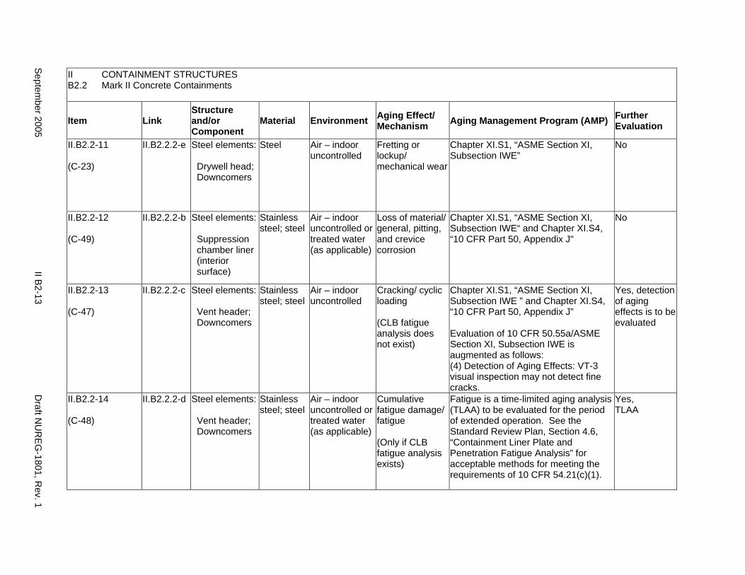
II CONTAINMENT STRUCTURES B2.2 Mark II Concrete Containments
Item Link Structure and/or Component
Material Environment Aging Effect/ Mechanism Aging Management Program (AMP) Further
Evaluation
II.B2.2-11
(C-23)
II.B2.2.2-e Steel elements:
Drywell head; Downcomers
Steel Air – indoor uncontrolled
Fretting or lockup/ mechanical wear
Chapter XI.S1, “ASME Section XI, Subsection IWE”
No
II.B2.2-12
(C-49)
II.B2.2.2-b Steel elements:
Suppression chamber liner (interior surface)
Stainless steel; steel
Air – indoor uncontrolled or treated water (as applicable)
Loss of material/ general, pitting, and crevice corrosion
Chapter XI.S1, “ASME Section XI, Subsection IWE“ and Chapter XI.S4, “10 CFR Part 50, Appendix J"
No
II.B2.2-13
(C-47)
II.B2.2.2-c Steel elements:
Vent header; Downcomers
Stainless steel; steel
Air – indoor uncontrolled
Cracking/ cyclic loading
(CLB fatigue analysis does not exist)
Chapter XI.S1, “ASME Section XI, Subsection IWE ” and Chapter XI.S4, “10 CFR Part 50, Appendix J”
Evaluation of 10 CFR 50.55a/ASME Section XI, Subsection IWE is augmented as follows: (4) Detection of Aging Effects: VT-3 visual inspection may not detect fine cracks.
Yes, detection of aging effects is to be evaluated
II.B2.2-14
(C-48)
II.B2.2.2-d Steel elements:
Vent header; Downcomers
Stainless steel; steel
Air – indoor uncontrolled or treated water (as applicable)
Cumulative fatigue damage/ fatigue
(Only if CLB fatigue analysis exists)
Fatigue is a time-limited aging analysis (TLAA) to be evaluated for the period of extended operation. See the Standard Review Plan, Section 4.6, “Containment Liner Plate and Penetration Fatigue Analysis” for acceptable methods for meeting the requirements of 10 CFR 54.21(c)(1).
Yes, TLAA
Septem
ber 2005 II B
2-13 D
raft NU
REG
-1801, Rev. 1
This Page Intentionally Left Blank
Draft N
UR
EG-1801, R
ev. 1 II B
2-14 S
eptember 2005
B3. MARK III CONTAINMENTS
B3.1 Steel Containments
B3.2 Concrete Containments
September 2005 II B3-1 Draft NUREG-1801, Rev. 1
This Page Intentionally Left Blank
Draft NUREG-1801, Rev. 1 II B3-2 September 2005
B3. MARK III CONTAINMENTS
Systems, Structures, and Components
This section addresses the elements of boiling water reactor (BWR) Mark III containment structures. Mark III steel containments are discussed in II.B3.1. Mark III concrete containments are discussed in II.B3.2.
System Interfaces
Functional interfaces include the primary containment heating and ventilation system (VII.F3), containment isolation system (V.C), and standby gas treatment system (V.B). Physical interfaces exist with any structure, system, or component that either penetrates the containment wall, such as the main steam system (VIII.B2) and feedwater system (VIII.D2), or is supported by the containment structure. The containment structure basemat may provide support to the NSSS components and containment internal structures.
September 2005 II B3-3 Draft NUREG-1801, Rev. 1
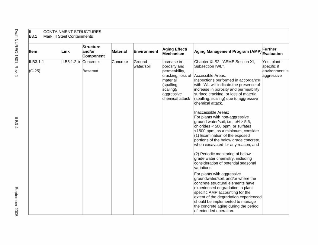
II CONTAINMENT STRUCTURES B3.1 Mark III Steel Containments
Item Link Structure and/or Component
Material Environment Aging Effect/ Mechanism Aging Management Program (AMP) Further
Evaluation
II.B3.1-1
(C-25)
II.B3.1.2-b Concrete:
Basemat
Concrete Ground water/soil
Increase in porosity and permeability, cracking, loss of material (spalling, scaling)/ aggressive chemical attack
Chapter XI.S2, “ASME Section XI, Subsection IWL”.
Accessible Areas: Inspections performed in accordance with IWL will indicate the presence of increase in porosity and permeability, surface cracking, or loss of material (spalling, scaling) due to aggressive chemical attack.
Inaccessible Areas: For plants with non-aggressive ground water/soil; i.e., pH > 5.5, chlorides < 500 ppm, or sulfates <1500 ppm, as a minimum, consider (1) Examination of the exposed portions of the below grade concrete, when excavated for any reason, and
(2) Periodic monitoring of below-grade water chemistry, including consideration of potential seasonal variations. For plants with aggressive groundwater/soil, and/or where the concrete structural elements have experienced degradation, a plant specific AMP accounting for the extent of the degradation experienced should be implemented to manage the concrete aging during the period of extended operation.
Yes, plant-specific if environment is aggressive
Draft N
UR
EG-1801, R
ev. 1 II B
3-4 S
eptember 2005
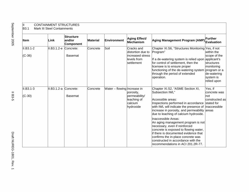
II CONTAINMENT STRUCTURES B3.1 Mark III Steel Containments
Item Link Structure and/or Component
Material Environment Aging Effect/ Mechanism Aging Management Program (AMP) Further
Evaluation
II.B3.1-2
(C-36)
II.B3.1.2-e Concrete:
Basemat
Concrete Soil Cracks and distortion due to increased stress levels from settlement
Chapter XI.S6, “Structures Monitoring Program”
If a de-watering system is relied upon for control of settlement, then the licensee is to ensure proper functioning of the de-watering system through the period of extended operation.
Yes, if not within the scope of the applicant’s structures monitoring program or a de-watering system is relied upon
II.B3.1-3
(C-30)
II.B3.1.2-a Concrete:
Basemat
Concrete Water – flowing Increase in porosity, permeability/ leaching of calcium hydroxide
Chapter XI.S2, “ASME Section XI, Subsection IWL”
Accessible areas: Inspections performed in accordance with IWL will indicate the presence of increase in porosity, and permeability due to leaching of calcium hydroxide. Inaccessible Areas: An aging management program is not necessary, even if reinforced concrete is exposed to flowing water, if there is documented evidence that confirms the in-place concrete was constructed in accordance with the recommendations in ACI 201.2R-77.
Yes, if concrete was not constructed as stated for inaccessible areas
Septem
ber 2005 II B
3-5 D
raft NU
REG
-1801, Rev. 1

II CONTAINMENT STRUCTURES B3.1 Mark III Steel Containments
Item Link Structure and/or Component
Material Environment Aging Effect/ Mechanism Aging Management Program (AMP) Further
Evaluation
II.B3.1-4
(C-50)
II.B3.1.2-g Concrete:
Basemat, concrete fill-in annulus
Concrete Air – indoor uncontrolled or air – outdoor
Reduction of strength and modulus/ elevated temperature (>150°F general; >200°F local)
Plant-specific aging management program
The implementation of 10 CFR 50.55a and ASME Section XI, Subsection IWL would not be able to identify the reduction of strength and modulus due to elevated temperature. Thus, for any portions of concrete containment that exceed specified temperature limits, further evaluations are warranted. Subsection CC-3400 of ASME Section III, Division 2, specifies the concrete temperature limits for normal operation or any other long-term period. The temperatures shall not exceed 150°F except for local areas, such as around penetrations, which are not allowed to exceed 200°F. If significant equipment loads are supported by concrete at temperatures exceeding 150°F, an evaluation of the ability to withstand the postulated design loads is to be made. Higher temperatures than given above may be allowed in the concrete if tests and/or calculations are provided to evaluate the reduction in strength and this reduction is applied to the design allowables.
Yes, if temperature limits are exceeded
Draft N
UR
EG-1801, R
ev. 1 II B
3-6 S
eptember 2005
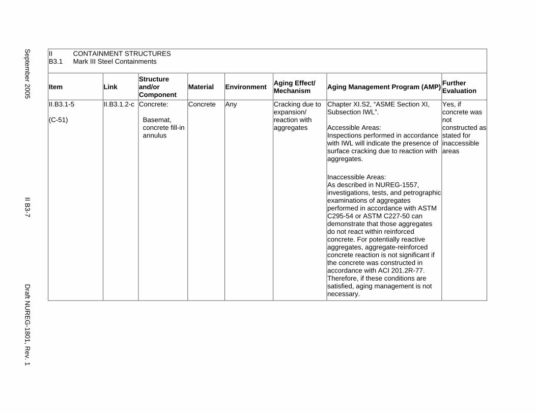
II CONTAINMENT STRUCTURES B3.1 Mark III Steel Containments
Item Link Structure and/or Component
Material Environment Aging Effect/ Mechanism Aging Management Program (AMP) Further
Evaluation
II.B3.1-5
(C-51)
II.B3.1.2-c Concrete:
Basemat, concrete fill-in annulus
Concrete Any Cracking due to expansion/ reaction with aggregates
Chapter XI.S2, “ASME Section XI, Subsection IWL”.
Accessible Areas: Inspections performed in accordance with IWL will indicate the presence of surface cracking due to reaction with aggregates.
Inaccessible Areas: As described in NUREG-1557, investigations, tests, and petrographic examinations of aggregates performed in accordance with ASTM C295-54 or ASTM C227-50 can demonstrate that those aggregates do not react within reinforced concrete. For potentially reactive aggregates, aggregate-reinforced concrete reaction is not significant if the concrete was constructed in accordance with ACI 201.2R-77. Therefore, if these conditions are satisfied, aging management is not necessary.
Yes, if concrete was not constructed as stated for inaccessible areas
Septem
ber 2005 II B
3-7 D
raft NU
REG
-1801, Rev. 1
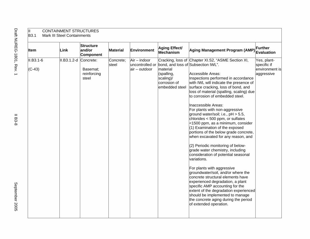
II CONTAINMENT STRUCTURES B3.1 Mark III Steel Containments
Item Link Structure and/or Component
Material Environment Aging Effect/ Mechanism Aging Management Program (AMP) Further
Evaluation
II.B3.1-6
(C-43)
II.B3.1.2-d Concrete:
Basemat; reinforcing steel
Concrete; steel
Air – indoor uncontrolled or air – outdoor
Cracking, loss of bond, and loss of material (spalling, scaling)/ corrosion of embedded steel
Chapter XI.S2, “ASME Section XI, Subsection IWL”.
Accessible Areas: Inspections performed in accordance with IWL will indicate the presence of surface cracking, loss of bond, and loss of material (spalling, scaling) due to corrosion of embedded steel.
Inaccessible Areas: For plants with non-aggressive ground water/soil; i.e., pH > 5.5, chlorides < 500 ppm, or sulfates <1500 ppm, as a minimum, consider (1) Examination of the exposed portions of the below grade concrete, when excavated for any reason, and
(2) Periodic monitoring of below-grade water chemistry, including consideration of potential seasonal variations.
For plants with aggressive groundwater/soil, and/or where the concrete structural elements have experienced degradation, a plant specific AMP accounting for the extent of the degradation experienced should be implemented to manage the concrete aging during the period of extended operation.
Yes, plant-specific if environment is aggressive
Draft N
UR
EG-1801, R
ev. 1 II B
3-8 S
eptember 2005
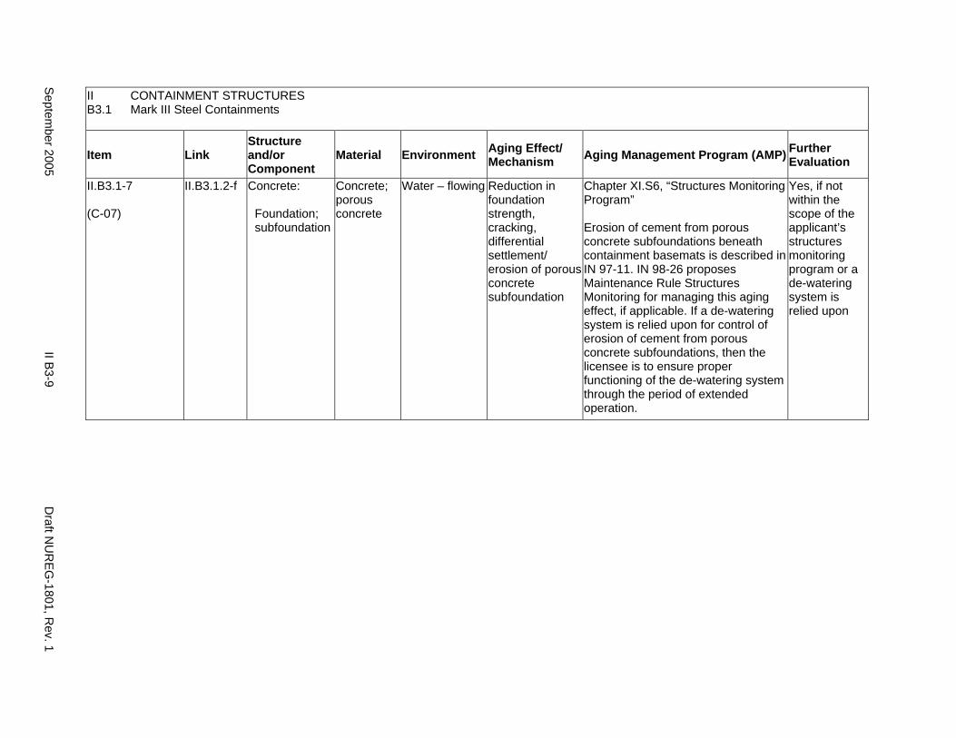
II CONTAINMENT STRUCTURES B3.1 Mark III Steel Containments
Item Link Structure and/or Component
Material Environment Aging Effect/ Mechanism Aging Management Program (AMP) Further
Evaluation
II.B3.1-7
(C-07)
II.B3.1.2-f Concrete:
Foundation; subfoundation
Concrete; porous concrete
Water – flowing Reduction in foundation strength, cracking, differential settlement/ erosion of porous concrete subfoundation
Chapter XI.S6, “Structures Monitoring Program”
Erosion of cement from porous concrete subfoundations beneath containment basemats is described in IN 97-11. IN 98-26 proposes Maintenance Rule Structures Monitoring for managing this aging effect, if applicable. If a de-watering system is relied upon for control of erosion of cement from porous concrete subfoundations, then the licensee is to ensure proper functioning of the de-watering system through the period of extended operation.
Yes, if not within the scope of the applicant’s structures monitoring program or a de-watering system is relied upon
Septem
ber 2005 II B
3-9 D
raft NU
REG
-1801, Rev. 1
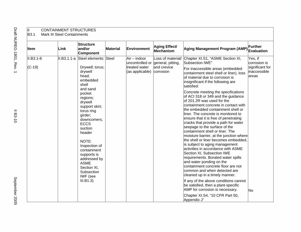
II CONTAINMENT STRUCTURES B3.1 Mark III Steel Containments
Item Link Structure and/or Component
Material Environment Aging Effect/ Mechanism Aging Management Program (AMP) Further
Evaluation
II.B3.1-8
(C-19)
II.B3.1.1-a Steel elements:
Drywell; torus; drywell head; embedded shell and sand pocket regions; drywell support skirt; torus ring girder; downcomers; ECCS suction header
NOTE: Inspection of containment supports is addressed by ASME Section XI, Subsection IWF (see III.B1.3)
Steel Air – indoor uncontrolled or treated water (as applicable)
Loss of material/ general, pitting, and crevice corrosion
Chapter XI.S1, “ASME Section XI, Subsection IWE” For inaccessible areas (embedded containment steel shell or liner), loss of material due to corrosion is insignificant if the following are satisfied: Concrete meeting the specifications of ACI 318 or 349 and the guidance of 201.2R was used for the containment concrete in contact with the embedded containment shell or liner. The concrete is monitored to ensure that it is free of penetrating cracks that provide a path for water seepage to the surface of the containment shell or liner. The moisture barrier, at the junction where the shell or liner becomes embedded, is subject to aging management activities in accordance with ASME Section XI, Subsection IWE requirements. Borated water spills and water ponding on the containment concrete floor are not common and when detected are cleaned up in a timely manner. If any of the above conditions cannot be satisfied, then a plant-specific AMP for corrosion is necessary. Chapter XI.S4, “10 CFR Part 50, Appendix J”
Yes, if corrosion is significant for inaccessible areas
No
Draft N
UR
EG-1801, R
ev. 1 II B
3-10 S
eptember 2005
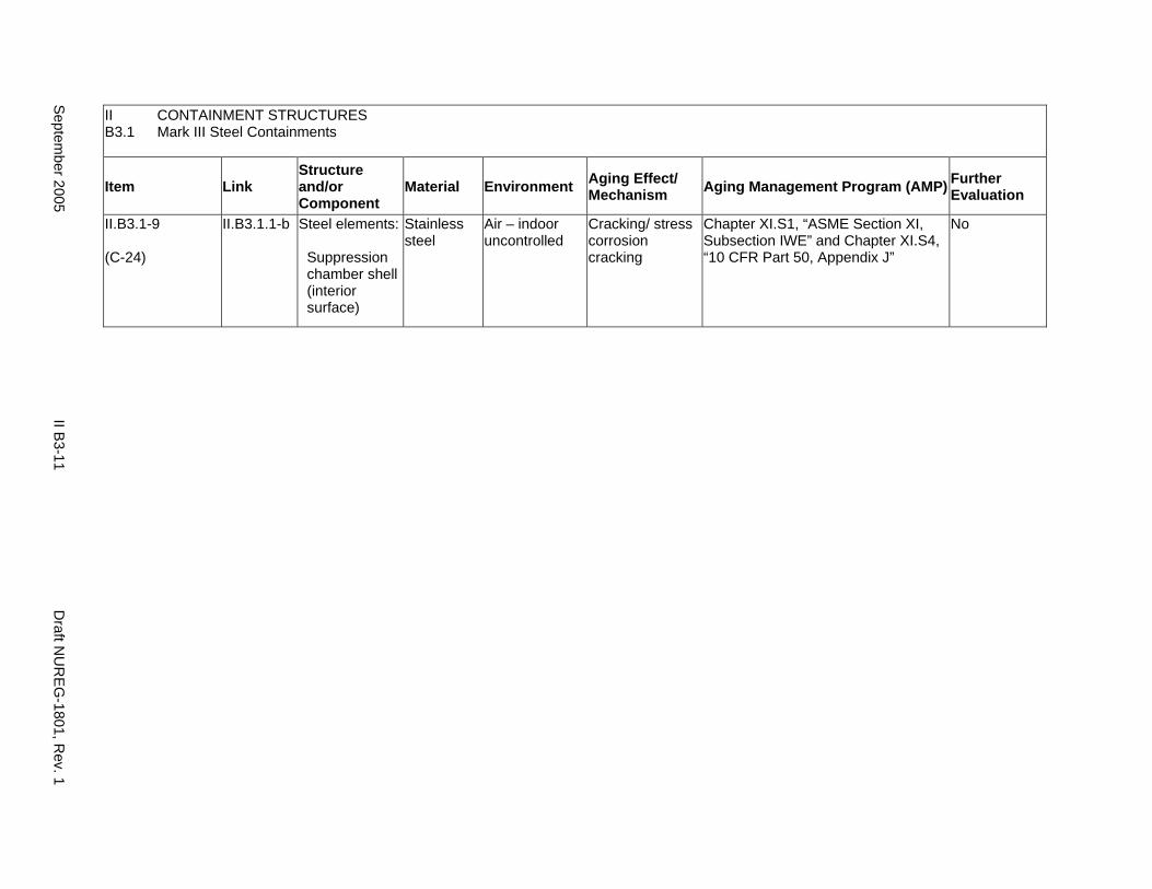
II CONTAINMENT STRUCTURES B3.1 Mark III Steel Containments
Item Link Structure and/or Component
Material Environment Aging Effect/ Mechanism Aging Management Program (AMP) Further
Evaluation
II.B3.1-9
(C-24)
II.B3.1.1-b Steel elements:
Suppression chamber shell (interior surface)
Stainless steel
Air – indoor uncontrolled
Cracking/ stress corrosion cracking
Chapter XI.S1, “ASME Section XI, Subsection IWE” and Chapter XI.S4, “10 CFR Part 50, Appendix J”
No
Septem
ber 2005 II B
3-11 D
raft NU
REG
-1801, Rev. 1
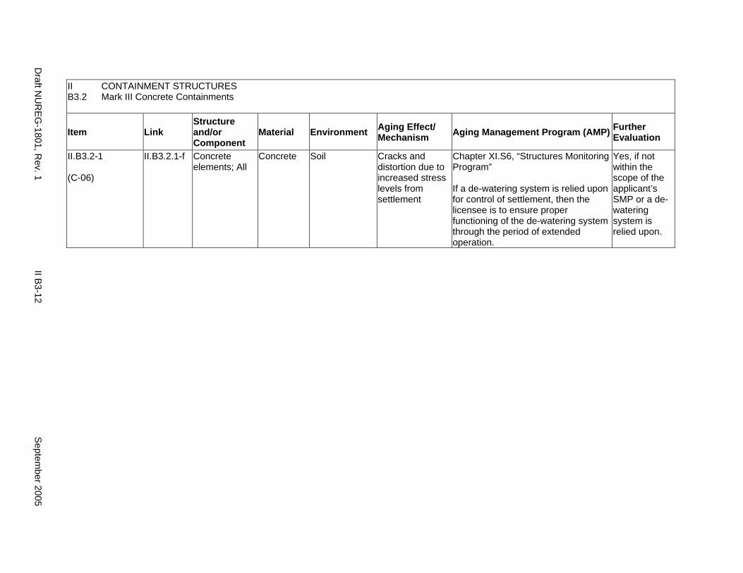
II CONTAINMENT STRUCTURES B3.2 Mark III Concrete Containments
Item Link Structure and/or Component
Material Environment Aging Effect/ Mechanism Aging Management Program (AMP) Further
Evaluation
II.B3.2-1
(C-06)
II.B3.2.1-f Concrete elements; All
Concrete Soil Cracks and distortion due to increased stress levels from settlement
Chapter XI.S6, “Structures Monitoring Program”
If a de-watering system is relied upon for control of settlement, then the licensee is to ensure proper functioning of the de-watering system through the period of extended operation.
Yes, if not within the scope of the applicant’s SMP or a dewatering system is relied upon.
Draft N
UR
EG-1801, R
ev. 1 II B
3-12 S
eptember 2005
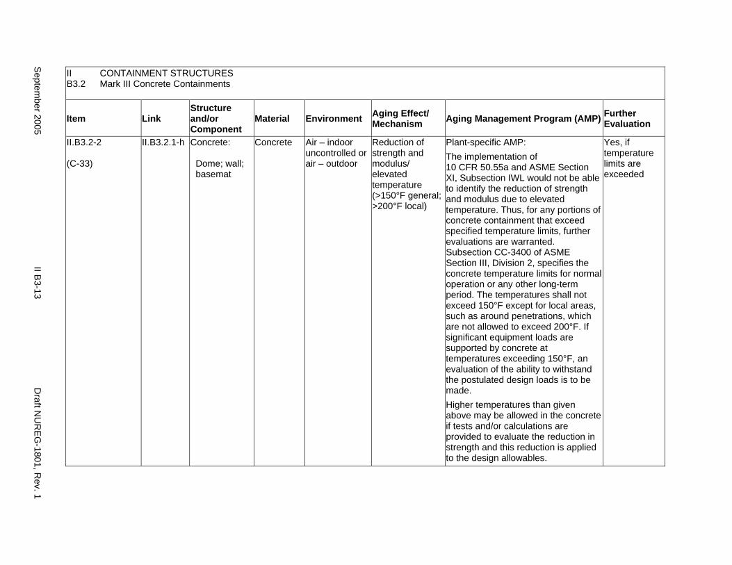
II CONTAINMENT STRUCTURES B3.2 Mark III Concrete Containments
Item Link Structure and/or Component
Material Environment Aging Effect/ Mechanism Aging Management Program (AMP) Further
Evaluation
II.B3.2-2
(C-33)
II.B3.2.1-h Concrete:
Dome; wall; basemat
Concrete Air – indoor uncontrolled or air – outdoor
Reduction of strength and modulus/ elevated temperature (>150°F general; >200°F local)
Plant-specific AMP: The implementation of 10 CFR 50.55a and ASME Section XI, Subsection IWL would not be able to identify the reduction of strength and modulus due to elevated temperature. Thus, for any portions of concrete containment that exceed specified temperature limits, further evaluations are warranted. Subsection CC-3400 of ASME Section III, Division 2, specifies the concrete temperature limits for normal operation or any other long-term period. The temperatures shall not exceed 150°F except for local areas, such as around penetrations, which are not allowed to exceed 200°F. If significant equipment loads are supported by concrete at temperatures exceeding 150°F, an evaluation of the ability to withstand the postulated design loads is to be made. Higher temperatures than given above may be allowed in the concrete if tests and/or calculations are provided to evaluate the reduction in strength and this reduction is applied to the design allowables.
Yes, if temperature limits are exceeded
Septem
ber 2005 II B
3-13 D
raft NU
REG
-1801, Rev. 1
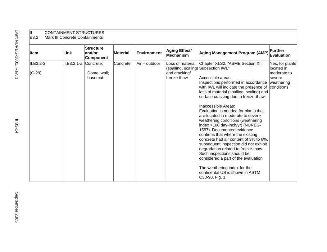
II CONTAINMENT STRUCTURES B3.2 Mark III Concrete Containments
Item Link Structure and/or Component
Material Environment Aging Effect/ Mechanism Aging Management Program (AMP) Further
Evaluation
II.B3.2-3
(C-29)
II.B3.2.1-a Concrete:
Dome; wall; basemat
Concrete Air – outdoor Loss of material (spalling, scaling) and cracking/ freeze-thaw
Chapter XI.S2, “ASME Section XI, Subsection IWL”
Accessible areas: Inspections performed in accordance with IWL will indicate the presence of loss of material (spalling, scaling) and surface cracking due to freeze-thaw.
Inaccessible Areas: Evaluation is needed for plants that are located in moderate to severe weathering conditions (weathering index >100 day-inch/yr) (NUREG1557). Documented evidence confirms that where the existing concrete had air content of 3% to 6%, subsequent inspection did not exhibit degradation related to freeze-thaw. Such inspections should be considered a part of the evaluation.
The weathering index for the continental US is shown in ASTM C33-90, Fig. 1.
Yes, for plants located in moderate to severe weathering conditions
Draft N
UR
EG-1801, R
ev. 1 II B
3-14 S
eptember 2005
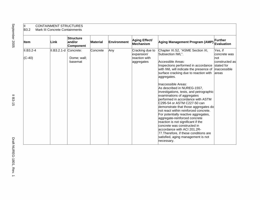
II CONTAINMENT STRUCTURES B3.2 Mark III Concrete Containments
Item Link Structure and/or Component
Material Environment Aging Effect/ Mechanism Aging Management Program (AMP) Further
Evaluation
II.B3.2-4
(C-40)
II.B3.2.1-d Concrete:
Dome; wall; basemat
Concrete Any Cracking due to expansion/ reaction with aggregates
Chapter XI.S2, “ASME Section XI, Subsection IWL”.
Accessible Areas: Inspections performed in accordance with IWL will indicate the presence of surface cracking due to reaction with aggregates.
Inaccessible Areas: As described in NUREG-1557, investigations, tests, and petrographic examinations of aggregates performed in accordance with ASTM C295-54 or ASTM C227-50 can demonstrate that those aggregates do not react within reinforced concrete. For potentially reactive aggregates, aggregate-reinforced concrete reaction is not significant if the concrete was constructed in accordance with ACI 201.2R77.Therefore, if these conditions are satisfied, aging management is not necessary.
Yes, if concrete was not constructed as stated for inaccessible areas
Septem
ber 2005 II B
3-15 D
raft NU
REG
-1801, Rev. 1
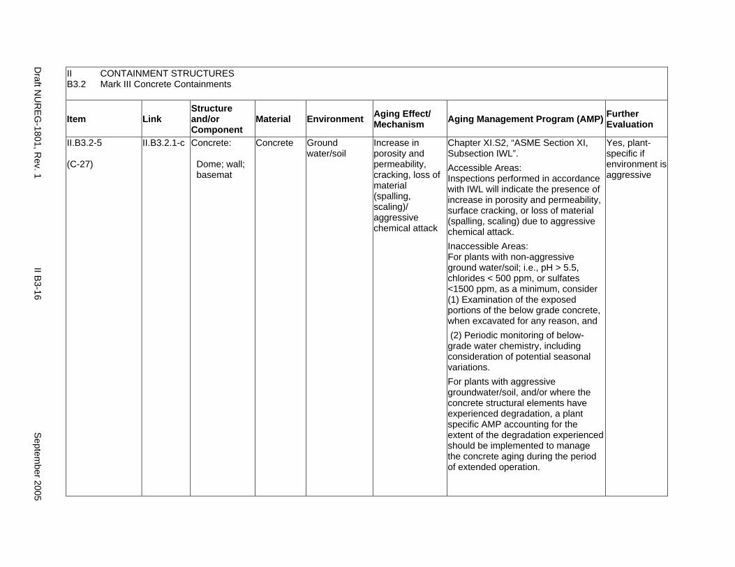
II CONTAINMENT STRUCTURES B3.2 Mark III Concrete Containments
Item Link Structure and/or Component
Material Environment Aging Effect/ Mechanism Aging Management Program (AMP) Further
Evaluation
II.B3.2-5
(C-27)
II.B3.2.1-c Concrete:
Dome; wall; basemat
Concrete Ground water/soil
Increase in porosity and permeability, cracking, loss of material (spalling, scaling)/ aggressive chemical attack
Chapter XI.S2, “ASME Section XI, Subsection IWL”. Accessible Areas: Inspections performed in accordance with IWL will indicate the presence of increase in porosity and permeability, surface cracking, or loss of material (spalling, scaling) due to aggressive chemical attack. Inaccessible Areas: For plants with non-aggressive ground water/soil; i.e., pH > 5.5, chlorides < 500 ppm, or sulfates <1500 ppm, as a minimum, consider (1) Examination of the exposed portions of the below grade concrete, when excavated for any reason, and (2) Periodic monitoring of below-grade water chemistry, including consideration of potential seasonal variations. For plants with aggressive groundwater/soil, and/or where the concrete structural elements have experienced degradation, a plant specific AMP accounting for the extent of the degradation experienced should be implemented to manage the concrete aging during the period of extended operation.
Yes, plant-specific if environment is aggressive
Draft N
UR
EG-1801, R
ev. 1 II B
3-16 S
eptember 2005

II CONTAINMENT STRUCTURES B3.2 Mark III Concrete Containments
Item Link Structure and/or Component
Material Environment Aging Effect/ Mechanism Aging Management Program (AMP) Further
Evaluation
II.B3.2-6
(C-32)
II.B3.2.1-b Concrete:
Dome; wall; basemat
Concrete Water – flowing Increase in porosity, permeability/ leaching of calcium hydroxide
Chapter XI.S2, “ASME Section XI, Subsection IWL”
Accessible areas: Inspections performed in accordance with IWL will indicate the presence of increase in porosity, and permeability due to leaching of calcium hydroxide.
Inaccessible Areas: An aging management program is not necessary, even if reinforced concrete is exposed to flowing water, if there is documented evidence that confirms the in-place concrete was constructed in accordance with the recommendations in ACI 201.2R-77.
Yes, if concrete was not constructed as stated for inaccessible areas
Septem
ber 2005 II B
3-17 D
raft NU
REG
-1801, Rev. 1

II CONTAINMENT STRUCTURES B3.2 Mark III Concrete Containments
Item Link Structure and/or Component
Material Environment Aging Effect/ Mechanism Aging Management Program (AMP) Further
Evaluation
II.B3.2-7
(C-42)
II.B3.2.1-e Concrete:
Dome; wall; basemat; reinforcing steel
Concrete; steel
Air – indoor uncontrolled or air – outdoor
Cracking, loss of bond, and loss of material (spalling, scaling)/ corrosion of embedded steel
Chapter XI.S2, “ASME Section XI, Subsection IWL”.
Accessible Areas: Inspections performed in accordance with IWL will indicate the presence of surface cracking, loss of bond, and loss of material (spalling, scaling) due to corrosion of embedded steel.
Inaccessible Areas: For plants with non-aggressive ground water/soil; i.e., pH > 5.5, chlorides < 500 ppm, or sulfates <1500 ppm, as a minimum, consider (1) Examination of the exposed portions of the below grade concrete, when excavated for any reason, and (2) Periodic monitoring of below-grade water chemistry, including consideration of potential seasonal variations.
For plants with aggressive groundwater/soil, and/or where the concrete structural elements have experienced degradation, a plant specific AMP accounting for the extent of the degradation experienced should be implemented to manage the concrete aging during the period of extended operation.
Yes, plant-specific if environment is aggressive
Draft N
UR
EG-1801, R
ev. 1 II B
3-18 S
eptember 2005

II CONTAINMENT STRUCTURES B3.2 Mark III Concrete Containments
Item Link Structure and/or Component
Material Environment Aging Effect/ Mechanism Aging Management Program (AMP) Further
Evaluation
II.B3.2-8
(C-07)
II.B3.2.1-g Concrete:
Foundation; subfoundatio n
Concrete; porous concrete
Water – flowing Reduction in foundation strength, cracking, differential settlement/ erosion of porous concrete subfoundation
Chapter XI.S6, “Structures Monitoring Program”
Erosion of cement from porous concrete subfoundations beneath containment basemats is described in IN 97-11. IN 98-26 proposes Maintenance Rule Structures Monitoring for managing this aging effect, if applicable. If a de-watering system is relied upon for control of erosion of cement from porous concrete subfoundations, then the licensee is to ensure proper functioning of the de-watering system through the period of extended operation.
Yes, if not within the scope of the applicant’s structures monitoring program or a de-watering system is relied upon
Septem
ber 2005 II B
3-19 D
raft NU
REG
-1801, Rev. 1
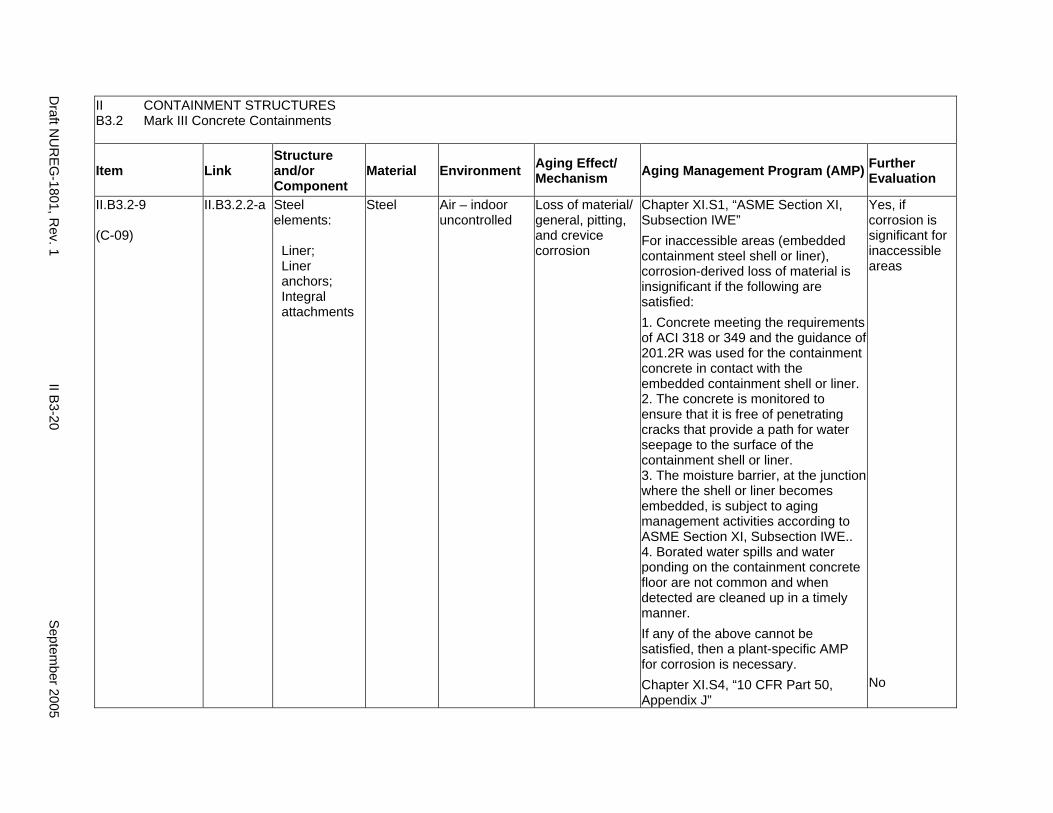
II CONTAINMENT STRUCTURES B3.2 Mark III Concrete Containments
Item Link Structure and/or Component
Material Environment Aging Effect/ Mechanism Aging Management Program (AMP) Further
Evaluation
II.B3.2-9
(C-09)
II.B3.2.2-a Steel elements:
Liner; Liner anchors; Integral attachments
Steel Air – indoor uncontrolled
Loss of material/ general, pitting, and crevice corrosion
Chapter XI.S1, “ASME Section XI, Subsection IWE” For inaccessible areas (embedded containment steel shell or liner), corrosion-derived loss of material is insignificant if the following are satisfied: 1. Concrete meeting the requirements of ACI 318 or 349 and the guidance of 201.2R was used for the containment concrete in contact with the embedded containment shell or liner. 2. The concrete is monitored to ensure that it is free of penetrating cracks that provide a path for water seepage to the surface of the containment shell or liner. 3. The moisture barrier, at the junction where the shell or liner becomes embedded, is subject to aging management activities according to ASME Section XI, Subsection IWE.. 4. Borated water spills and water ponding on the containment concrete floor are not common and when detected are cleaned up in a timely manner. If any of the above cannot be satisfied, then a plant-specific AMP for corrosion is necessary. Chapter XI.S4, “10 CFR Part 50, Appendix J”
Yes, if corrosion is significant for inaccessible areas
No
Draft N
UR
EG-1801, R
ev. 1 II B
3-20 S
eptember 2005
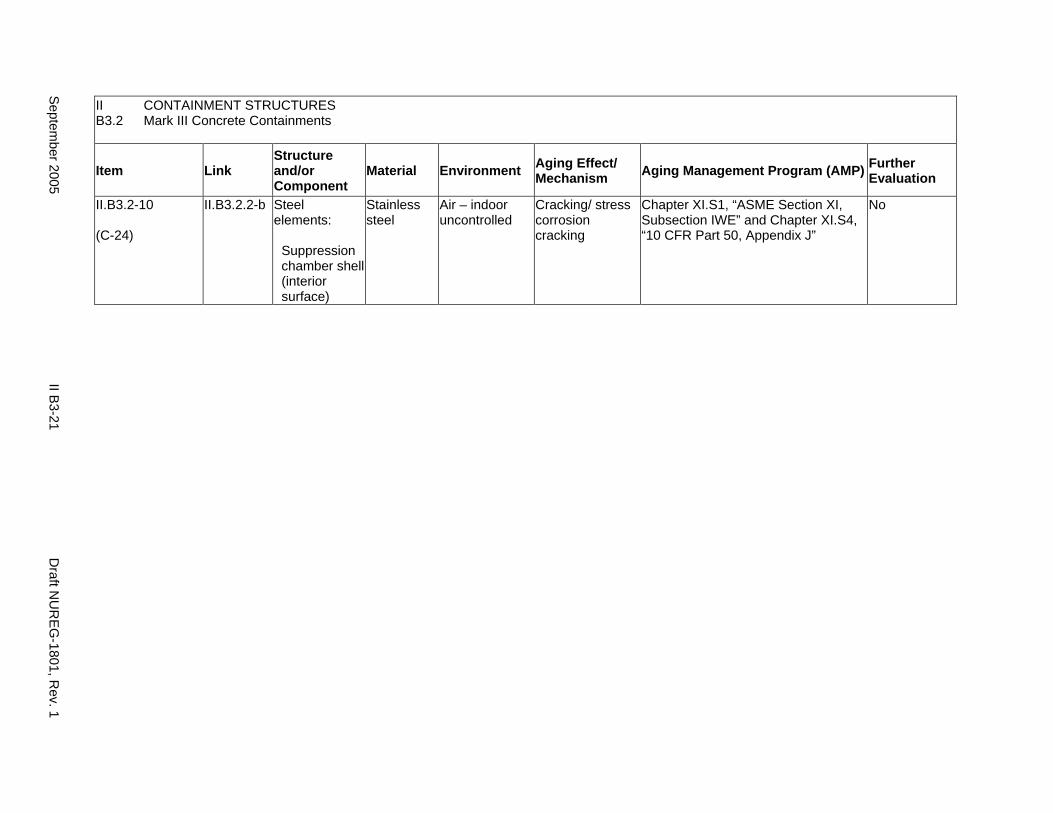
II CONTAINMENT STRUCTURES B3.2 Mark III Concrete Containments
Item Link Structure and/or Component
Material Environment Aging Effect/ Mechanism Aging Management Program (AMP) Further
Evaluation
II.B3.2-10
(C-24)
II.B3.2.2-b Steel elements:
Suppression chamber shell (interior surface)
Stainless steel
Air – indoor uncontrolled
Cracking/ stress corrosion cracking
Chapter XI.S1, “ASME Section XI, Subsection IWE” and Chapter XI.S4, “10 CFR Part 50, Appendix J”
No
Septem
ber 2005 II B
3-21 D
raft NU
REG
-1801, Rev. 1
This Page Intentionally Left Blank
Draft NUREG-1801, Rev. 1 II B3-22 September 2005
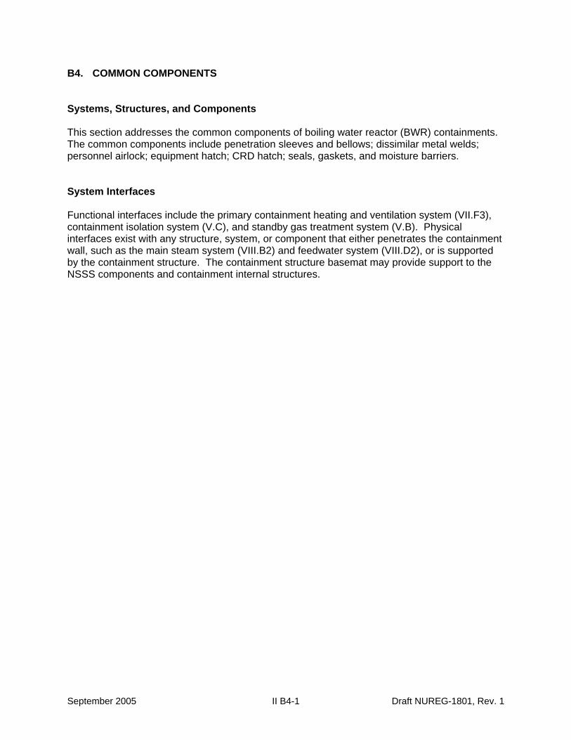
B4. COMMON COMPONENTS
Systems, Structures, and Components
This section addresses the common components of boiling water reactor (BWR) containments. The common components include penetration sleeves and bellows; dissimilar metal welds; personnel airlock; equipment hatch; CRD hatch; seals, gaskets, and moisture barriers.
System Interfaces
Functional interfaces include the primary containment heating and ventilation system (VII.F3), containment isolation system (V.C), and standby gas treatment system (V.B). Physical interfaces exist with any structure, system, or component that either penetrates the containment wall, such as the main steam system (VIII.B2) and feedwater system (VIII.D2), or is supported by the containment structure. The containment structure basemat may provide support to the NSSS components and containment internal structures.
September 2005 II B4-1 Draft NUREG-1801, Rev. 1
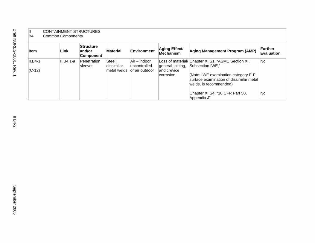
II B4
CONTAINMENT STRUCTURES Common Components
Item Link Structure and/or Component
Material Environment Aging Effect/ Mechanism Aging Management Program (AMP) Further
Evaluation
II.B4-1
(C-12)
II.B4.1-a Penetration sleeves
Steel; dissimilar metal welds
Air – indoor uncontrolled or air outdoor
Loss of material/ general, pitting, and crevice corrosion
Chapter XI.S1, “ASME Section XI, Subsection IWE,”
(Note: IWE examination category E-F, surface examination of dissimilar metal welds, is recommended)
Chapter XI.S4, “10 CFR Part 50, Appendix J”
No
No
Draft N
UR
EG-1801, R
ev. 1 II B
4-2 S
eptember 2005
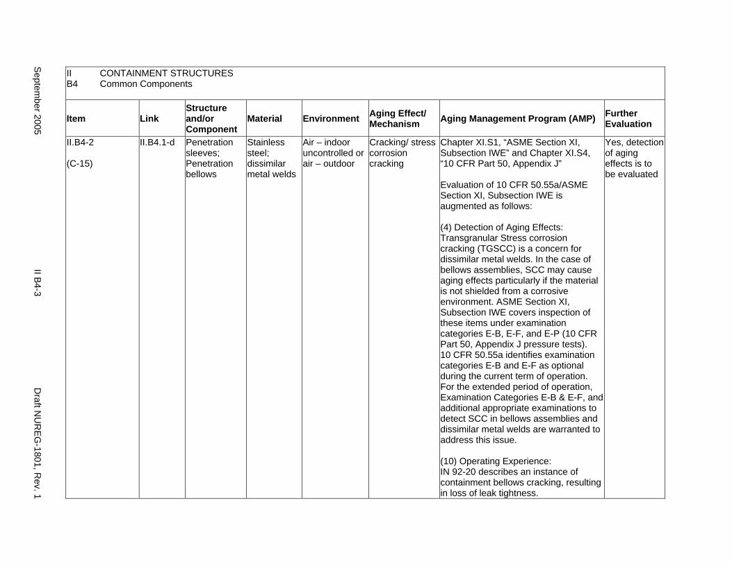
II B4
CONTAINMENT STRUCTURES Common Components
Item Link Structure and/or Component
Material Environment Aging Effect/ Mechanism Aging Management Program (AMP) Further
Evaluation
II.B4-2
(C-15)
II.B4.1-d Penetration sleeves; Penetration bellows
Stainless steel; dissimilar metal welds
Air – indoor uncontrolled or air – outdoor
Cracking/ stress corrosion cracking
Chapter XI.S1, “ASME Section XI, Subsection IWE” and Chapter XI.S4, “10 CFR Part 50, Appendix J”
Evaluation of 10 CFR 50.55a/ASME Section XI, Subsection IWE is augmented as follows:
(4) Detection of Aging Effects: Transgranular Stress corrosion cracking (TGSCC) is a concern for dissimilar metal welds. In the case of bellows assemblies, SCC may cause aging effects particularly if the material is not shielded from a corrosive environment. ASME Section XI, Subsection IWE covers inspection of these items under examination categories E-B, E-F, and E-P (10 CFR Part 50, Appendix J pressure tests). 10 CFR 50.55a identifies examination categories E-B and E-F as optional during the current term of operation. For the extended period of operation, Examination Categories E-B & E-F, and additional appropriate examinations to detect SCC in bellows assemblies and dissimilar metal welds are warranted to address this issue.
(10) Operating Experience: IN 92-20 describes an instance of containment bellows cracking, resulting in loss of leak tightness.
Yes, detection of aging effects is to be evaluated
Septem
ber 2005 II B
4-3 D
raft NU
REG
-1801, Rev. 1
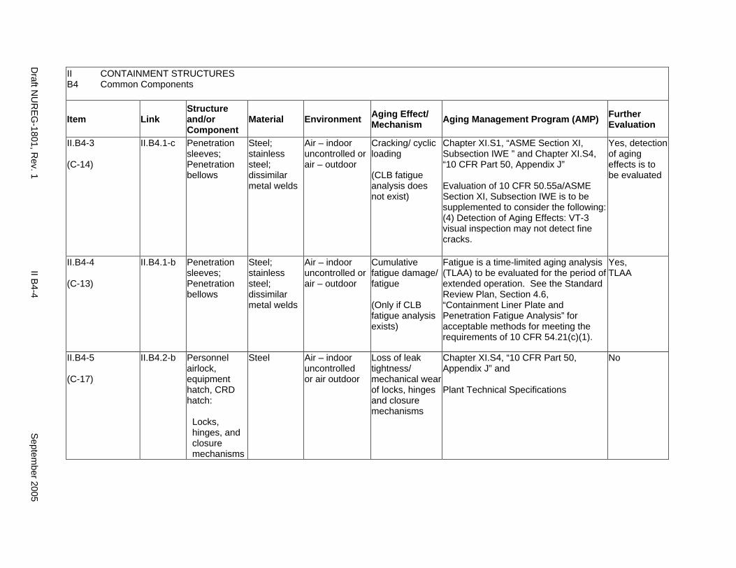
II B4
CONTAINMENT STRUCTURES Common Components
Item Link Structure and/or Component
Material Environment Aging Effect/ Mechanism Aging Management Program (AMP) Further
Evaluation
II.B4-3
(C-14)
II.B4.1-c Penetration sleeves; Penetration bellows
Steel; stainless steel; dissimilar metal welds
Air – indoor uncontrolled or air – outdoor
Cracking/ cyclic loading
(CLB fatigue analysis does not exist)
Chapter XI.S1, “ASME Section XI, Subsection IWE ” and Chapter XI.S4, “10 CFR Part 50, Appendix J”
Evaluation of 10 CFR 50.55a/ASME Section XI, Subsection IWE is to be supplemented to consider the following: (4) Detection of Aging Effects: VT-3 visual inspection may not detect fine cracks.
Yes, detection of aging effects is to be evaluated
II.B4-4
(C-13)
II.B4.1-b Penetration sleeves; Penetration bellows
Steel; stainless steel; dissimilar metal welds
Air – indoor uncontrolled or air – outdoor
Cumulative fatigue damage/ fatigue
(Only if CLB fatigue analysis exists)
Fatigue is a time-limited aging analysis (TLAA) to be evaluated for the period of extended operation. See the Standard Review Plan, Section 4.6, “Containment Liner Plate and Penetration Fatigue Analysis” for acceptable methods for meeting the requirements of 10 CFR 54.21(c)(1).
Yes, TLAA
II.B4-5
(C-17)
II.B4.2-b Personnel airlock, equipment hatch, CRD hatch:
Locks, hinges, and closure mechanisms
Steel Air – indoor uncontrolled or air outdoor
Loss of leak tightness/ mechanical wear of locks, hinges and closure mechanisms
Chapter XI.S4, “10 CFR Part 50, Appendix J” and
Plant Technical Specifications
No
Draft N
UR
EG-1801, R
ev. 1 II B
4-4 S
eptember 2005
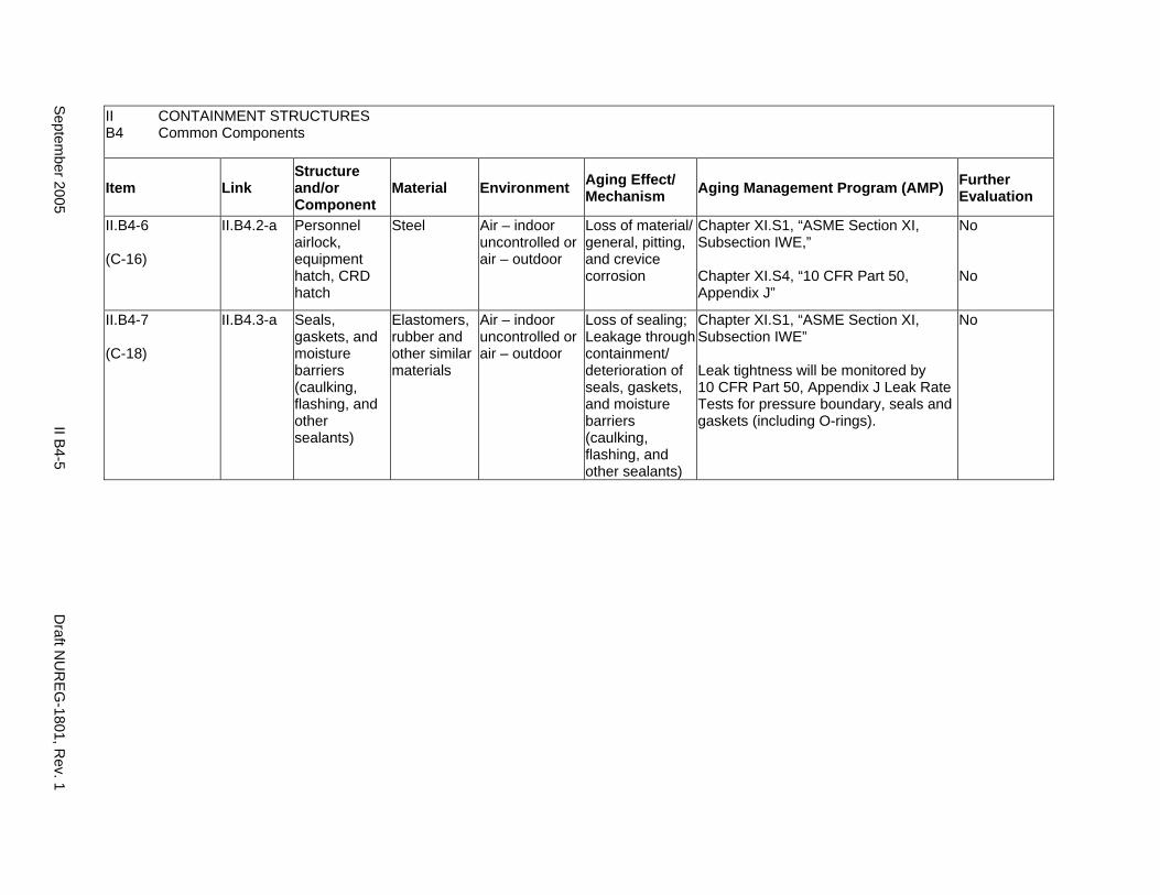
II CONTAINMENT STRUCTURES B4 Common Components
Item Link Structure and/or Component
Material Environment Aging Effect/ Mechanism Aging Management Program (AMP) Further
Evaluation
II.B4-6
(C-16)
II.B4.2-a Personnel airlock, equipment hatch, CRD hatch
Steel Air – indoor uncontrolled or air – outdoor
Loss of material/ general, pitting, and crevice corrosion
Chapter XI.S1, “ASME Section XI, Subsection IWE,”
Chapter XI.S4, “10 CFR Part 50, Appendix J”
No
No
II.B4-7
(C-18)
II.B4.3-a Seals, gaskets, and moisture barriers (caulking, flashing, and other sealants)
Elastomers, rubber and other similar materials
Air – indoor uncontrolled or air – outdoor
Loss of sealing; Leakage through containment/ deterioration of seals, gaskets, and moisture barriers (caulking, flashing, and other sealants)
Chapter XI.S1, “ASME Section XI, Subsection IWE”
Leak tightness will be monitored by 10 CFR Part 50, Appendix J Leak Rate Tests for pressure boundary, seals and gaskets (including O-rings).
No
Septem
ber 2005 II B
4-5 D
raft NU
REG
-1801, Rev. 1
This Page Intentionally Left Blank
Draft NUREG-1801, Rev. 1 II B4-6 September 2005
CHAPTER III
STRUCTURES AND COMPONENT SUPPORTS
September 2005 III-i Draft NUREG-1801, Rev. 1

This Page Intentionally Left Blank
Draft NUREG-1801, Rev. 1 III-ii September 2005
STRUCTURES AND COMPONENT SUPPORTS
Chapter III A: Safety Related and Other Structures
Safety related structures are those structures defined pursuant to 10 CFR 54.4(a)(1) and the other structures are those defined pursuant to 10 CFR 54.4(a)(2) and 10 CFR 54.4(a)(3). Structures in this section are organized into nine groups and are discussed separately under subheadings A1 through A9.
Chapter III B: Component Supports
Component supports include supports for ASME piping and components; supports for cable trays, conduit, HVAC ducts, tubetrack, instrument tubing, non-ASME piping and components; anchorage of racks, panels, cabinets, and enclosures for electrical equipment and instrumentation; supports for emergency diesel generator (EDG) and HVAC system components; and supports for platforms, pipe whip restraints, jet impingement shields, masonry walls, and other miscellaneous structures.
September 2005 III-iii Draft NUREG-1801, Rev. 1
DraftD
raftDraft N
UR
EG
1801, Rev. 1
III A2-iv
Septem
ber 2005 -
This Page Intentionally Left Blank
Draft NUREG-1801, Rev. 1 III-iv September 2005
III.A SAFETY RELATED AND OTHER STRUCTURES
A1. Group 1 Structures (BWR Reactor Bldg., PWR Shield Bldg., Control Rm./Bldg.)
A2. Group 2 Structures (BWR Reactor Bldg. with Steel Superstructure)
A3. Group 3 Structures (Auxiliary Bldg., Diesel Generator Bldg., Radwaste Bldg., Turbine Bldg., Switchgear Rm., Yard Structures such as AFW Pumphouse, Utility/Piping Tunnels, Security/Lighting Poles, Manholes, Duct Banks; SBO Structures such as Transmission Towers, Startup Towers Circuit Breaker Foundation, Electrical Enclosure)
A4. Group 4 Structures (Containment Internal Structures, excluding Refueling Canal)
A5. Group 5 Structures (Fuel Storage Facility, Refueling Canal)
A6. Group 6 Structures (Water-Control Structures)
A7. Group 7 Structures (Concrete Tanks and Missile Barriers)
A8. Group 8 Structures (Steel Tanks and Missile Barriers)
A9. Group 9 Structures (BWR Unit Vent Stack)
September 2005 III A-1 Draft NUREG-1801, Rev. 1

DraftD
raftDraft N
UR
EG
1801, Rev. 1
III A1-2
Septem
ber 2005 -
This Page Intentionally Left Blank
Draft NUREG-1801, Rev. 1 III A-2 September 2005
A1. GROUP 1 STRUCTURES (BWR REACTOR BLDG., PWR SHIELD BLDG., CONTROL RM./BLDG.)
Systems, Structures, and Components
This section addresses the elements of boiling water reactor (BWR) reactor building, pressurized water reactor (PWR) shield building, and control room/building. For this group, the applicable structural elements are concrete, steel, and masonry walls. The aging management review is presented for each applicable combination of structural element and aging effect.
System Interfaces
Physical interfaces exist with any system or component that either penetrates the structure wall or is supported by the structure wall, floor, and roof. The direct interface is through the system or component supports that are anchored to the structure. Structures also protect housed systems or components from internal and external design basis events. In the case of tanks, there is a functional interface with the associated system. Water-control structures are integral parts of the systems that provide plant cooling water and residual heat removal.
September 2005 III A1-1 Draft NUREG-1801, Rev. 1
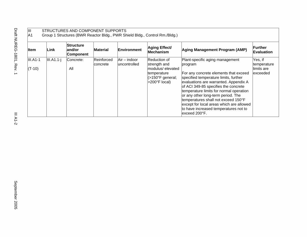
III STRUCTURES AND COMPONENT SUPPORTS A1 Group 1 Structures (BWR Reactor Bldg., PWR Shield Bldg., Control Rm./Bldg.)
Item Link Structure and/or Component
Material Environment Aging Effect/ Mechanism Aging Management Program (AMP) Further
Evaluation
III.A1-1
(T-10)
III.A1.1-j Concrete:
All
Reinforced concrete
Air – indoor uncontrolled
Reduction of strength and modulus/ elevated temperature (>150°F general; >200°F local)
Plant-specific aging management program
For any concrete elements that exceed specified temperature limits, further evaluations are warranted. Appendix A of ACI 349-85 specifies the concrete temperature limits for normal operation or any other long-term period. The temperatures shall not exceed 150°F except for local areas which are allowed to have increased temperatures not to exceed 200°F.
Yes, if temperature limits are exceeded
Draft N
UR
EG-1801, R
ev. 1 III A
1-2 S
eptember 2005
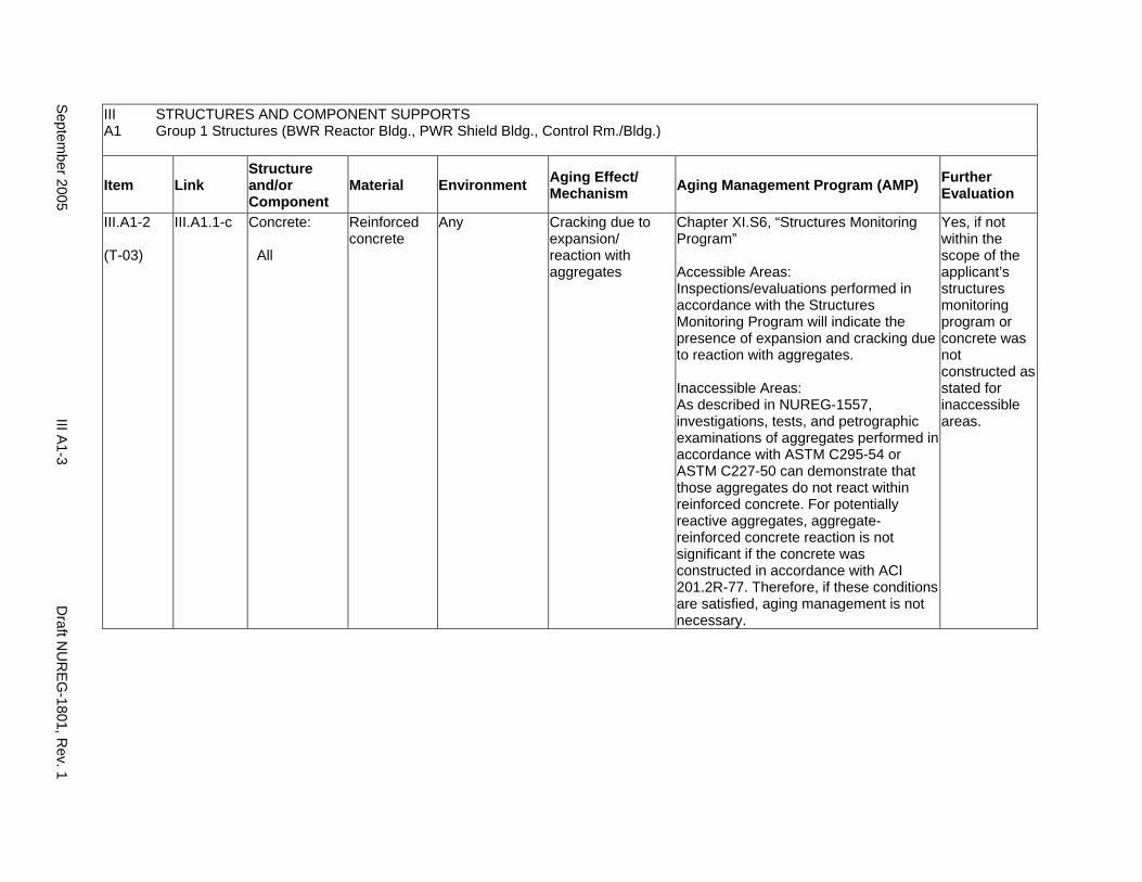
III STRUCTURES AND COMPONENT SUPPORTS A1 Group 1 Structures (BWR Reactor Bldg., PWR Shield Bldg., Control Rm./Bldg.)
Item Link Structure and/or Component
Material Environment Aging Effect/ Mechanism Aging Management Program (AMP) Further
Evaluation
III.A1-2
(T-03)
III.A1.1-c Concrete:
All
Reinforced concrete
Any Cracking due to expansion/ reaction with aggregates
Chapter XI.S6, “Structures Monitoring Program”
Accessible Areas: Inspections/evaluations performed in accordance with the Structures Monitoring Program will indicate the presence of expansion and cracking due to reaction with aggregates.
Inaccessible Areas: As described in NUREG-1557, investigations, tests, and petrographic examinations of aggregates performed in accordance with ASTM C295-54 or ASTM C227-50 can demonstrate that those aggregates do not react within reinforced concrete. For potentially reactive aggregates, aggregate-reinforced concrete reaction is not significant if the concrete was constructed in accordance with ACI 201.2R-77. Therefore, if these conditions are satisfied, aging management is not necessary.
Yes, if not within the scope of the applicant’s structures monitoring program or concrete was not constructed as stated for inaccessible areas.
Septem
ber 2005 III A
1-3 D
raft NU
REG
-1801, Rev. 1
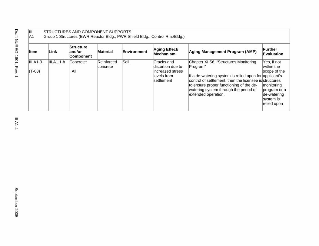
III STRUCTURES AND COMPONENT SUPPORTS A1 Group 1 Structures (BWR Reactor Bldg., PWR Shield Bldg., Control Rm./Bldg.)
Item Link Structure and/or Component
Material Environment Aging Effect/ Mechanism Aging Management Program (AMP) Further
Evaluation
III.A1-3
(T-08)
III.A1.1-h Concrete:
All
Reinforced concrete
Soil Cracks and distortion due to increased stress levels from settlement
Chapter XI.S6, “Structures Monitoring Program”
If a de-watering system is relied upon for control of settlement, then the licensee is to ensure proper functioning of the dewatering system through the period of extended operation.
Yes, if not within the scope of the applicant’s structures monitoring program or a de-watering system is relied upon
Draft N
UR
EG-1801, R
ev. 1 III A
1-4 S
eptember 2005
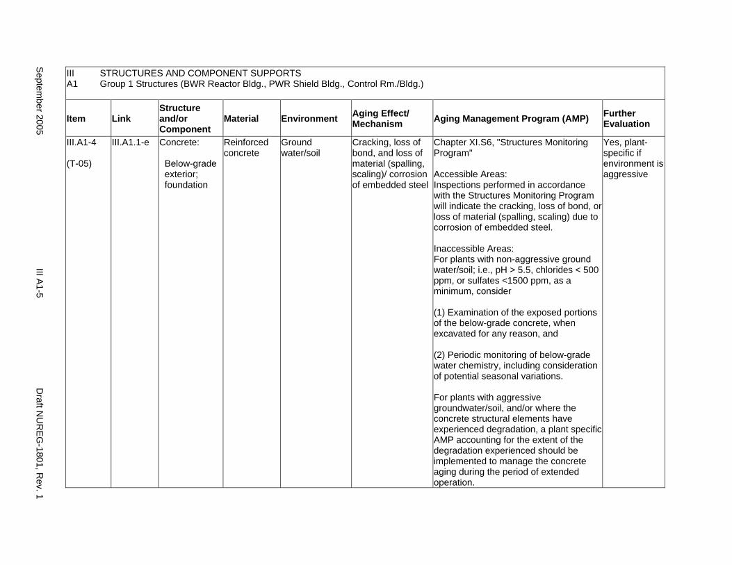
III A1
STRUCTURES AND COMPONENT SUPPORTS Group 1 Structures (BWR Reactor Bldg., PWR Shield Bldg., Control Rm./Bldg.)
Item Link Structure and/or Component
Material Environment Aging Effect/ Mechanism Aging Management Program (AMP) Further
Evaluation
III.A1-4
(T-05)
III.A1.1-e Concrete:
Below-grade exterior; foundation
Reinforced concrete
Ground water/soil
Cracking, loss of bond, and loss of material (spalling, scaling)/ corrosion of embedded steel
Chapter XI.S6, "Structures Monitoring Program"
Accessible Areas: Inspections performed in accordance with the Structures Monitoring Program will indicate the cracking, loss of bond, or loss of material (spalling, scaling) due to corrosion of embedded steel.
Inaccessible Areas: For plants with non-aggressive ground water/soil; i.e., pH > 5.5, chlorides < 500 ppm, or sulfates <1500 ppm, as a minimum, consider
(1) Examination of the exposed portions of the below-grade concrete, when excavated for any reason, and
(2) Periodic monitoring of below-grade water chemistry, including consideration of potential seasonal variations.
For plants with aggressive groundwater/soil, and/or where the concrete structural elements have experienced degradation, a plant specific AMP accounting for the extent of the degradation experienced should be implemented to manage the concrete aging during the period of extended operation.
Yes, plant-specific if environment is aggressive
Septem
ber 2005 III A
1-5 D
raft NU
REG
-1801, Rev. 1

III STRUCTURES AND COMPONENT SUPPORTS A1 Group 1 Structures (BWR Reactor Bldg., PWR Shield Bldg., Control Rm./Bldg.)
Item Link Structure and/or Component
Material Environment Aging Effect/ Mechanism Aging Management Program (AMP) Further
Evaluation
III.A1-5
(T-07)
III.A1.1-g Concrete:
Below-grade exterior; foundation
Reinforced concrete
Ground water/soil
Increase in porosity and permeability, cracking, loss of material (spalling, scaling)/ aggressive chemical attack
Inaccessible Areas: For plants with non-aggressive ground water/soil; i.e., pH > 5.5, chlorides < 500 ppm, or sulfates <1500 ppm, as a minimum, consider
(1) Examination of the exposed portions of the below-grade concrete, when excavated for any reason, and
(2) Periodic monitoring of below-grade water chemistry, including consideration of potential seasonal variations.
For plants with aggressive groundwater/soil, and/or where the concrete structural elements have experienced degradation, a plant specific AMP accounting for the extent of the degradation experienced should be implemented to manage the concrete aging during the period of extended operation.
Yes, plant-specific if environment is aggressive
Draft N
UR
EG-1801, R
ev. 1 III A
1-6 S
eptember 2005
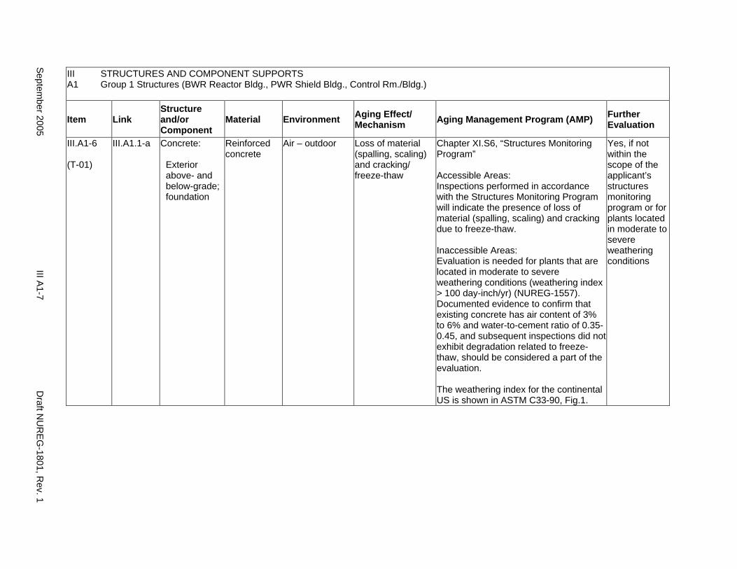
III STRUCTURES AND COMPONENT SUPPORTS A1 Group 1 Structures (BWR Reactor Bldg., PWR Shield Bldg., Control Rm./Bldg.)
Item Link Structure and/or Component
Material Environment Aging Effect/ Mechanism Aging Management Program (AMP) Further
Evaluation
III.A1-6
(T-01)
III.A1.1-a Concrete:
Exterior above- and below-grade; foundation
Reinforced concrete
Air – outdoor Loss of material (spalling, scaling) and cracking/ freeze-thaw
Chapter XI.S6, “Structures Monitoring Program”
Accessible Areas: Inspections performed in accordance with the Structures Monitoring Program will indicate the presence of loss of material (spalling, scaling) and cracking due to freeze-thaw.
Inaccessible Areas: Evaluation is needed for plants that are located in moderate to severe weathering conditions (weathering index > 100 day-inch/yr) (NUREG-1557). Documented evidence to confirm that existing concrete has air content of 3% to 6% and water-to-cement ratio of 0.350.45, and subsequent inspections did not exhibit degradation related to freeze-thaw, should be considered a part of the evaluation.
The weathering index for the continental US is shown in ASTM C33-90, Fig.1.
Yes, if not within the scope of the applicant’s structures monitoring program or for plants located in moderate to severe weathering conditions
Septem
ber 2005 III A
1-7 D
raft NU
REG
-1801, Rev. 1
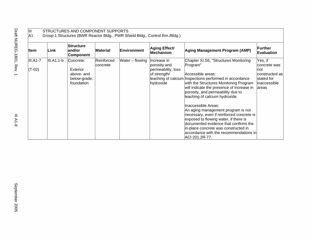
III A1
STRUCTURES AND COMPONENT SUPPORTS Group 1 Structures (BWR Reactor Bldg., PWR Shield Bldg., Control Rm./Bldg.)
Item Link Structure and/or Component
Material Environment Aging Effect/ Mechanism Aging Management Program (AMP) Further
Evaluation
III.A1-7
(T-02)
III.A1.1-b Concrete:
Exterior above- and below-grade; foundation
Reinforced concrete
Water – flowing Increase in porosity and permeability, loss of strength/ leaching of calcium hydroxide
Chapter XI.S6, "Structures Monitoring Program"
Accessible areas: Inspections performed in accordance with the Structures Monitoring Program will indicate the presence of increase in porosity, and permeability due to leaching of calcium hydroxide.
Inaccessible Areas: An aging management program is not necessary, even if reinforced concrete is exposed to flowing water, if there is documented evidence that confirms the in-place concrete was constructed in accordance with the recommendations in ACI 201.2R-77.
Yes, if concrete was not constructed as stated for inaccessible areas
Draft N
UR
EG-1801, R
ev. 1 III A
1-8 S
eptember 2005
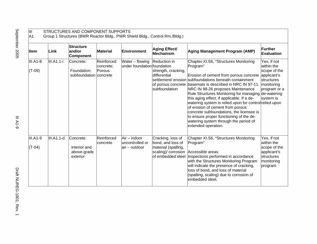
III A1
STRUCTURES AND COMPONENT SUPPORTS Group 1 Structures (BWR Reactor Bldg., PWR Shield Bldg., Control Rm./Bldg.)
Item Link Structure and/or Component
Material Environment Aging Effect/ Mechanism Aging Management Program (AMP) Further
Evaluation
III.A1-8
(T-09)
III.A1.1-i Concrete:
Foundation; subfoundation
Reinforced concrete; Porous concrete
Water – flowing under foundation
Reduction in foundation strength, cracking, differential settlement/ erosion of porous concrete subfoundation
Chapter XI.S6, “Structures Monitoring Program”
Erosion of cement from porous concrete subfoundations beneath containment basemats is described in NRC IN 97-11. NRC IN 98-26 proposes Maintenance Rule Structures Monitoring for managing this aging effect, if applicable. If a dewatering system is relied upon for control of erosion of cement from porous concrete subfoundations, the licensee is to ensure proper functioning of the dewatering system through the period of extended operation.
Yes, if not within the scope of the applicant’s structures monitoring program or a de-watering system is relied upon
III.A1-9
(T-04)
III.A1.1-d Concrete:
Interior and above-grade exterior
Reinforced concrete
Air – indoor uncontrolled or air – outdoor
Cracking, loss of bond, and loss of material (spalling, scaling)/ corrosion of embedded steel
Chapter XI.S6, “Structures Monitoring Program”
Accessible areas: Inspections performed in accordance with the Structures Monitoring Program will indicate the presence of cracking, loss of bond, and loss of material (spalling, scaling) due to corrosion of embedded steel.
Yes, if not within the scope of the applicant’s structures monitoring program
Septem
ber 2005 III A
1-9 D
raft NU
REG
-1801, Rev. 1
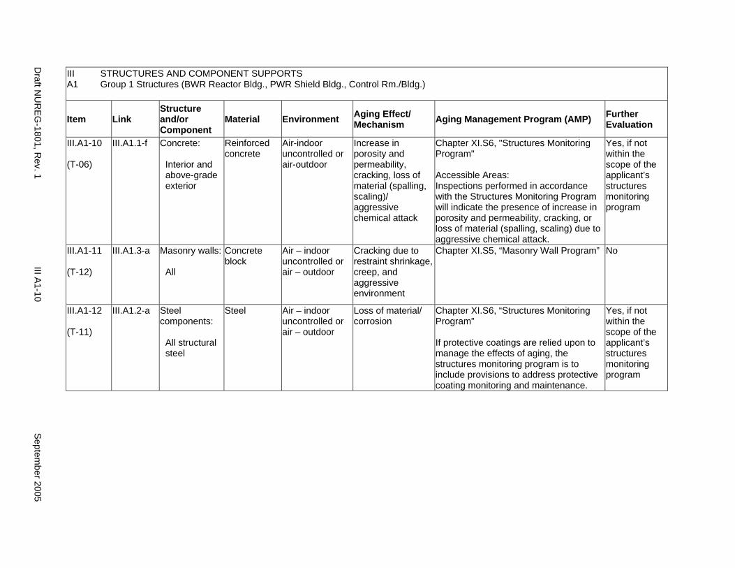
III STRUCTURES AND COMPONENT SUPPORTS A1 Group 1 Structures (BWR Reactor Bldg., PWR Shield Bldg., Control Rm./Bldg.)
Item Link Structure and/or Component
Material Environment Aging Effect/ Mechanism Aging Management Program (AMP) Further
Evaluation
III.A1-10
(T-06)
III.A1.1-f Concrete:
Interior and above-grade exterior
Reinforced concrete
Air-indoor uncontrolled or air-outdoor
Increase in porosity and permeability, cracking, loss of material (spalling, scaling)/ aggressive chemical attack
Chapter XI.S6, "Structures Monitoring Program"
Accessible Areas: Inspections performed in accordance with the Structures Monitoring Program will indicate the presence of increase in porosity and permeability, cracking, or loss of material (spalling, scaling) due to aggressive chemical attack.
Yes, if not within the scope of the applicant’s structures monitoring program
III.A1-11
(T-12)
III.A1.3-a Masonry walls:
All
Concrete block
Air – indoor uncontrolled or air – outdoor
Cracking due to restraint shrinkage, creep, and aggressive environment
Chapter XI.S5, “Masonry Wall Program” No
III.A1-12
(T-11)
III.A1.2-a Steel components:
All structural steel
Steel Air – indoor uncontrolled or air – outdoor
Loss of material/ corrosion
Chapter XI.S6, “Structures Monitoring Program”
If protective coatings are relied upon to manage the effects of aging, the structures monitoring program is to include provisions to address protective coating monitoring and maintenance.
Yes, if not within the scope of the applicant’s structures monitoring program
Draft N
UR
EG-1801, R
ev. 1 III A
1-10 S
eptember 2005
A2. GROUP 2 STRUCTURES (BWR REACTOR BLDG. WITH STEEL SUPERSTRUCTURE)
Systems, Structures, and Components
This section addresses the elements of boiling water reactor (BWR) reactor building with steel superstructure. For this group, the applicable structural elements are identified: concrete, steel, and masonry walls. The aging management review is presented for each applicable combination of structural element and aging effect.
System Interfaces
Physical interfaces exist with any system or component that either penetrates the structure wall or is supported by the structure wall, floor, and roof. The direct interface is through the system or component supports that are anchored to the structure. Structures also protect housed systems and components from internal and external design basis events. In the case of tanks, there is a functional interface with the associated system. Water-control structures are integral parts of the systems that provide plant cooling water and residual heat removal.
September 2005 III A2-1 Draft NUREG-1801, Rev. 1
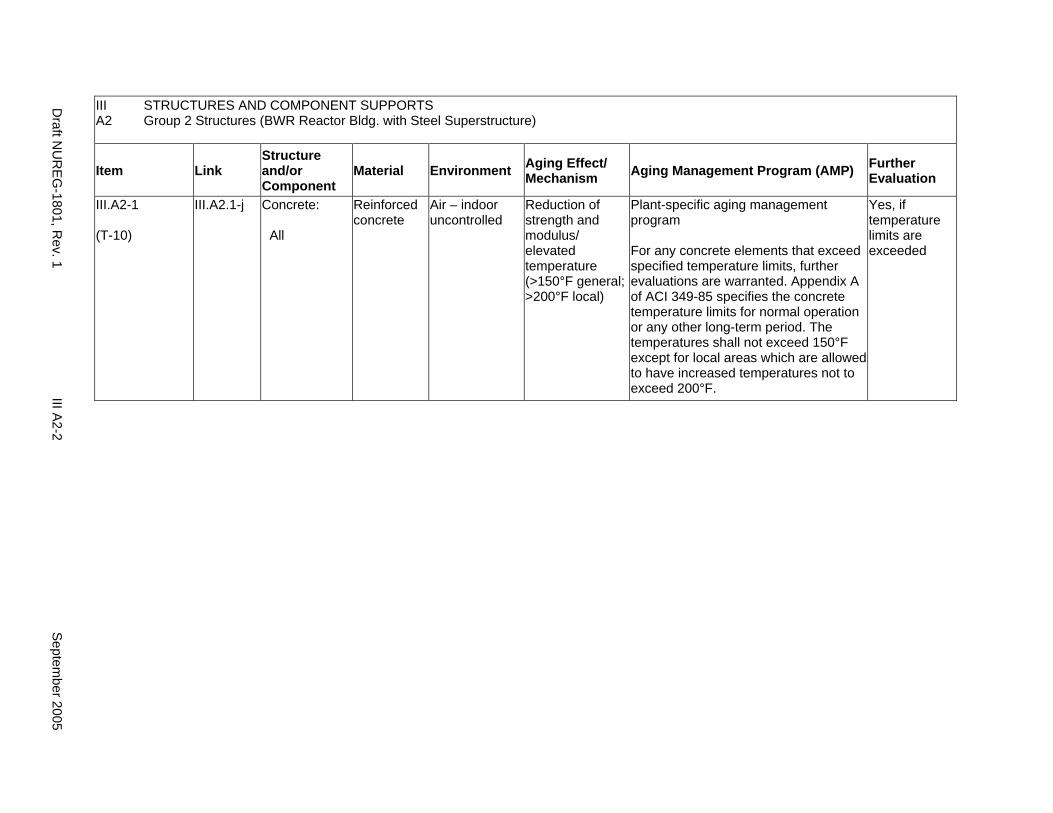
III A2
STRUCTURES AND COMPONENT SUPPORTS Group 2 Structures (BWR Reactor Bldg. with Steel Superstructure)
Item Link Structure and/or Component
Material Environment Aging Effect/ Mechanism Aging Management Program (AMP) Further
Evaluation
III.A2-1
(T-10)
III.A2.1-j Concrete:
All
Reinforced concrete
Air – indoor uncontrolled
Reduction of strength and modulus/ elevated temperature (>150°F general; >200°F local)
Plant-specific aging management program
For any concrete elements that exceed specified temperature limits, further evaluations are warranted. Appendix A of ACI 349-85 specifies the concrete temperature limits for normal operation or any other long-term period. The temperatures shall not exceed 150°F except for local areas which are allowed to have increased temperatures not to exceed 200°F.
Yes, if temperature limits are exceeded
Draft N
UR
EG-1801, R
ev. 1 III A
2-2 S
eptember 2005
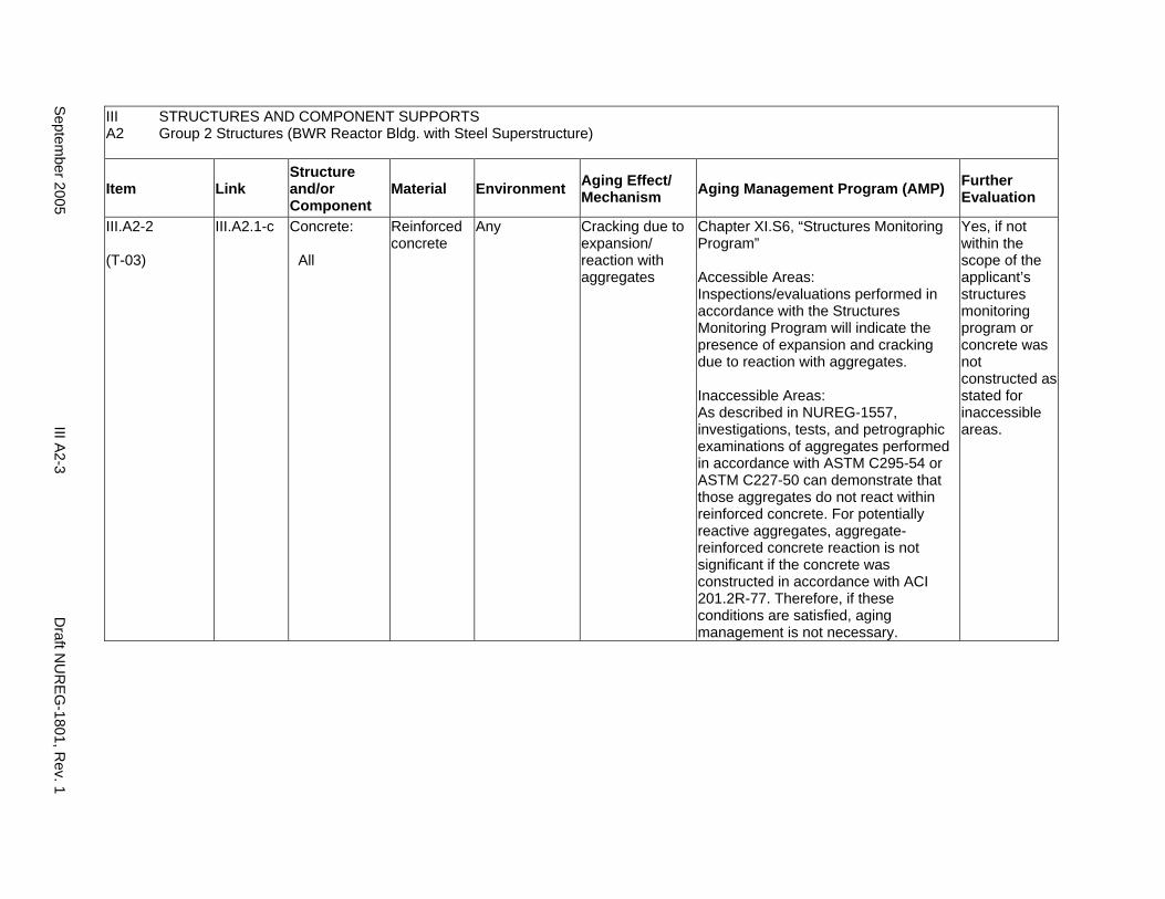
III STRUCTURES AND COMPONENT SUPPORTS A2 Group 2 Structures (BWR Reactor Bldg. with Steel Superstructure)
Item Link Structure and/or Component
Material Environment Aging Effect/ Mechanism Aging Management Program (AMP) Further
Evaluation
III.A2-2
(T-03)
III.A2.1-c Concrete:
All
Reinforced concrete
Any Cracking due to expansion/ reaction with aggregates
Chapter XI.S6, “Structures Monitoring Program”
Accessible Areas: Inspections/evaluations performed in accordance with the Structures Monitoring Program will indicate the presence of expansion and cracking due to reaction with aggregates.
Inaccessible Areas: As described in NUREG-1557, investigations, tests, and petrographic examinations of aggregates performed in accordance with ASTM C295-54 or ASTM C227-50 can demonstrate that those aggregates do not react within reinforced concrete. For potentially reactive aggregates, aggregate-reinforced concrete reaction is not significant if the concrete was constructed in accordance with ACI 201.2R-77. Therefore, if these conditions are satisfied, aging management is not necessary.
Yes, if not within the scope of the applicant’s structures monitoring program or concrete was not constructed as stated for inaccessible areas.
Septem
ber 2005 III A
2-3 D
raft NU
REG
-1801, Rev. 1
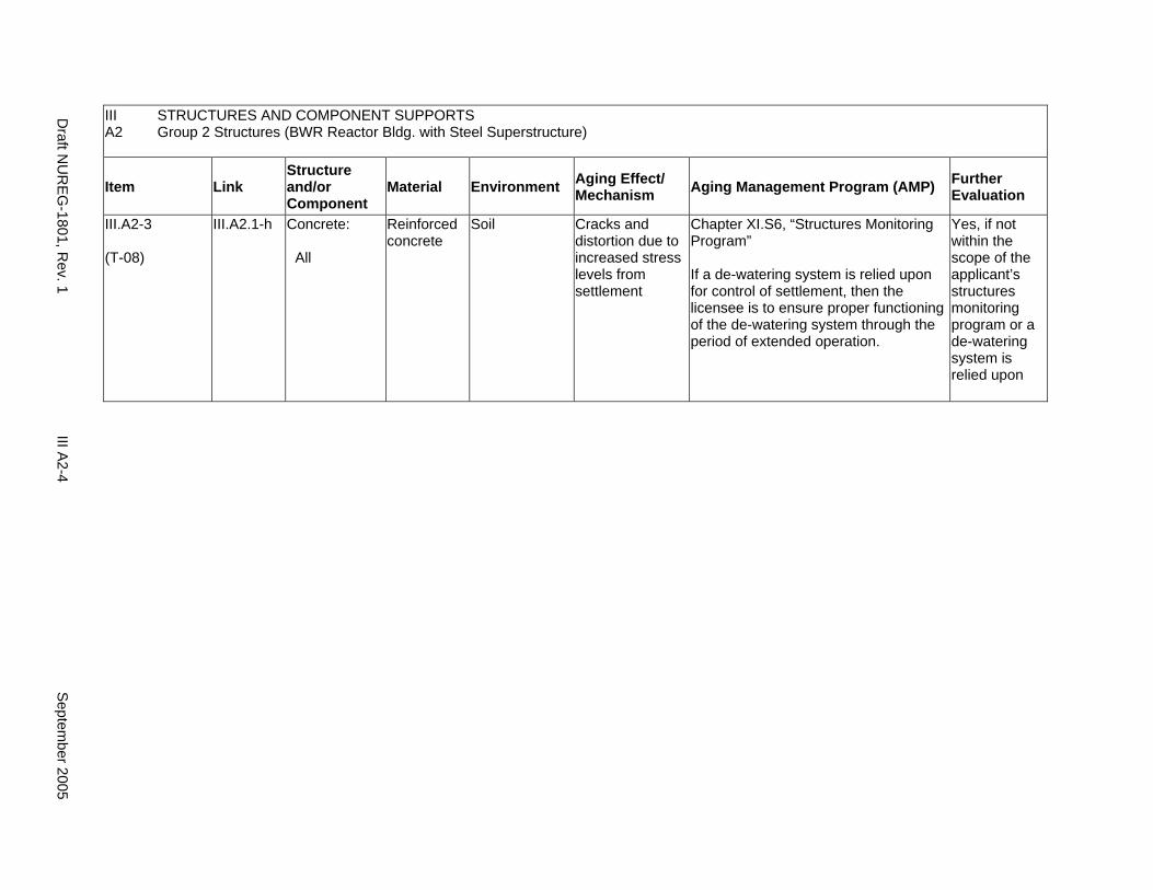
III STRUCTURES AND COMPONENT SUPPORTS A2 Group 2 Structures (BWR Reactor Bldg. with Steel Superstructure)
Item Link Structure and/or Component
Material Environment Aging Effect/ Mechanism Aging Management Program (AMP) Further
Evaluation
III.A2-3
(T-08)
III.A2.1-h Concrete:
All
Reinforced concrete
Soil Cracks and distortion due to increased stress levels from settlement
Chapter XI.S6, “Structures Monitoring Program”
If a de-watering system is relied upon for control of settlement, then the licensee is to ensure proper functioning of the de-watering system through the period of extended operation.
Yes, if not within the scope of the applicant’s structures monitoring program or a de-watering system is relied upon
Draft N
UR
EG-1801, R
ev. 1 III A
2-4 S
eptember 2005
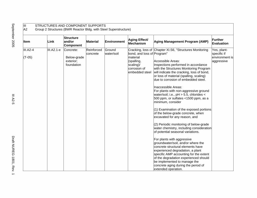
III A2
STRUCTURES AND COMPONENT SUPPORTS Group 2 Structures (BWR Reactor Bldg. with Steel Superstructure)
Item Link Structure and/or Component
Material Environment Aging Effect/ Mechanism Aging Management Program (AMP) Further
Evaluation
III.A2-4
(T-05)
III.A2.1-e Concrete:
Below-grade exterior; foundation
Reinforced concrete
Ground water/soil
Cracking, loss of bond, and loss of material (spalling, scaling)/ corrosion of embedded steel
Chapter XI.S6, "Structures Monitoring Program"
Accessible Areas: Inspections performed in accordance with the Structures Monitoring Program will indicate the cracking, loss of bond, or loss of material (spalling, scaling) due to corrosion of embedded steel.
Inaccessible Areas: For plants with non-aggressive ground water/soil; i.e., pH > 5.5, chlorides < 500 ppm, or sulfates <1500 ppm, as a minimum, consider
(1) Examination of the exposed portions of the below-grade concrete, when excavated for any reason, and
(2) Periodic monitoring of below-grade water chemistry, including consideration of potential seasonal variations.
For plants with aggressive groundwater/soil, and/or where the concrete structural elements have experienced degradation, a plant specific AMP accounting for the extent of the degradation experienced should be implemented to manage the concrete aging during the period of extended operation.
Yes, plant-specific if environment is aggressive
Septem
ber 2005 III A
2-5 D
raft NU
REG
-1801, Rev. 1
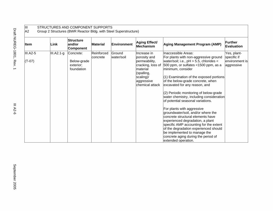
III STRUCTURES AND COMPONENT SUPPORTS A2 Group 2 Structures (BWR Reactor Bldg. with Steel Superstructure)
Item Link Structure and/or Component
Material Environment Aging Effect/ Mechanism Aging Management Program (AMP) Further
Evaluation
III.A2-5
(T-07)
III.A2.1-g Concrete:
Below-grade exterior; foundation
Reinforced concrete
Ground water/soil
Increase in porosity and permeability, cracking, loss of material (spalling, scaling)/ aggressive chemical attack
Inaccessible Areas: For plants with non-aggressive ground water/soil; i.e., pH > 5.5, chlorides < 500 ppm, or sulfates <1500 ppm, as a minimum, consider
(1) Examination of the exposed portions of the below-grade concrete, when excavated for any reason, and
(2) Periodic monitoring of below-grade water chemistry, including consideration of potential seasonal variations.
For plants with aggressive groundwater/soil, and/or where the concrete structural elements have experienced degradation, a plant specific AMP accounting for the extent of the degradation experienced should be implemented to manage the concrete aging during the period of extended operation.
Yes, plant-specific if environment is aggressive
Draft N
UR
EG-1801, R
ev. 1 III A
2-6 S
eptember 2005
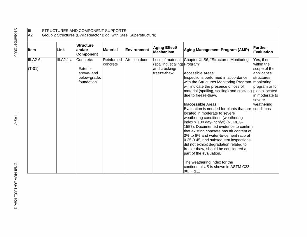
III A2
STRUCTURES AND COMPONENT SUPPORTS Group 2 Structures (BWR Reactor Bldg. with Steel Superstructure)
Item Link Structure and/or Component
Material Environment Aging Effect/ Mechanism Aging Management Program (AMP) Further
Evaluation
III.A2-6
(T-01)
III.A2.1-a Concrete:
Exterior above- and below-grade; foundation
Reinforced concrete
Air – outdoor Loss of material (spalling, scaling) and cracking/ freeze-thaw
Chapter XI.S6, “Structures Monitoring Program”
Accessible Areas: Inspections performed in accordance with the Structures Monitoring Program will indicate the presence of loss of material (spalling, scaling) and cracking due to freeze-thaw.
Inaccessible Areas: Evaluation is needed for plants that are located in moderate to severe weathering conditions (weathering index > 100 day-inch/yr) (NUREG1557). Documented evidence to confirm that existing concrete has air content of 3% to 6% and water-to-cement ratio of 0.35-0.45, and subsequent inspections did not exhibit degradation related to freeze-thaw, should be considered a part of the evaluation.
The weathering index for the continental US is shown in ASTM C3390, Fig.1.
Yes, if not within the scope of the applicant’s structures monitoring program or for plants located in moderate to severe weathering conditions
Septem
ber 2005 III A
2-7 D
raft NU
REG
-1801, Rev. 1
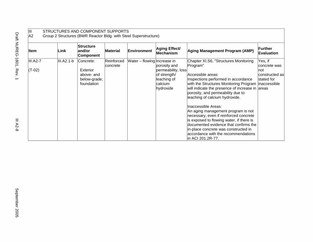
III A2
STRUCTURES AND COMPONENT SUPPORTS Group 2 Structures (BWR Reactor Bldg. with Steel Superstructure)
Item Link Structure and/or Component
Material Environment Aging Effect/ Mechanism Aging Management Program (AMP) Further
Evaluation
III.A2-7
(T-02)
III.A2.1-b Concrete:
Exterior above- and below-grade; foundation
Reinforced concrete
Water – flowing Increase in porosity and permeability, loss of strength/ leaching of calcium hydroxide
Chapter XI.S6, "Structures Monitoring Program"
Accessible areas: Inspections performed in accordance with the Structures Monitoring Program will indicate the presence of increase in porosity, and permeability due to leaching of calcium hydroxide.
Inaccessible Areas: An aging management program is not necessary, even if reinforced concrete is exposed to flowing water, if there is documented evidence that confirms the in-place concrete was constructed in accordance with the recommendations in ACI 201.2R-77.
Yes, if concrete was not constructed as stated for inaccessible areas
Draft N
UR
EG-1801, R
ev. 1 III A
2-8 S
eptember 2005
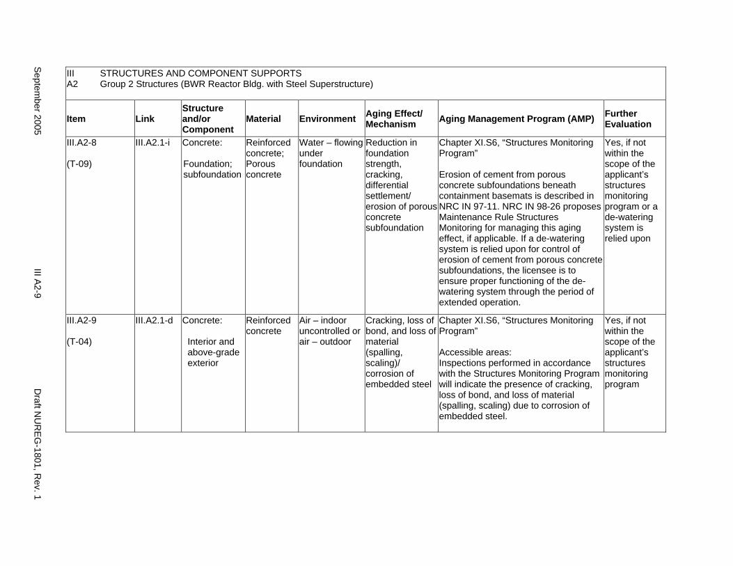
III A2
STRUCTURES AND COMPONENT SUPPORTS Group 2 Structures (BWR Reactor Bldg. with Steel Superstructure)
Item Link Structure and/or Component
Material Environment Aging Effect/ Mechanism Aging Management Program (AMP) Further
Evaluation
III.A2-8
(T-09)
III.A2.1-i Concrete:
Foundation; subfoundation
Reinforced concrete; Porous concrete
Water – flowing under foundation
Reduction in foundation strength, cracking, differential settlement/ erosion of porous concrete subfoundation
Chapter XI.S6, “Structures Monitoring Program”
Erosion of cement from porous concrete subfoundations beneath containment basemats is described in NRC IN 97-11. NRC IN 98-26 proposes Maintenance Rule Structures Monitoring for managing this aging effect, if applicable. If a de-watering system is relied upon for control of erosion of cement from porous concrete subfoundations, the licensee is to ensure proper functioning of the dewatering system through the period of extended operation.
Yes, if not within the scope of the applicant’s structures monitoring program or a de-watering system is relied upon
III.A2-9
(T-04)
III.A2.1-d Concrete:
Interior and above-grade exterior
Reinforced concrete
Air – indoor uncontrolled or air – outdoor
Cracking, loss of bond, and loss of material (spalling, scaling)/ corrosion of embedded steel
Chapter XI.S6, “Structures Monitoring Program”
Accessible areas: Inspections performed in accordance with the Structures Monitoring Program will indicate the presence of cracking, loss of bond, and loss of material (spalling, scaling) due to corrosion of embedded steel.
Yes, if not within the scope of the applicant’s structures monitoring program
Septem
ber 2005 III A
2-9 D
raft NU
REG
-1801, Rev. 1
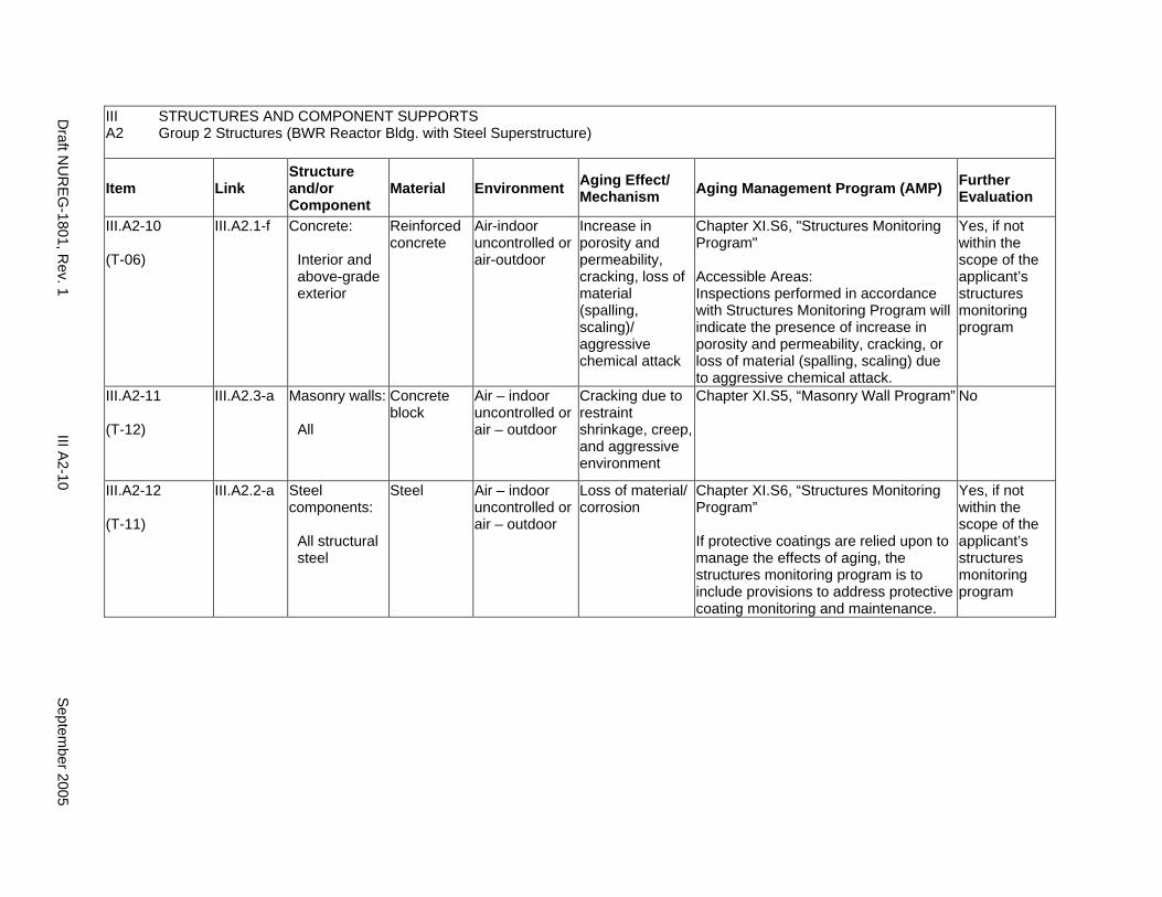
III STRUCTURES AND COMPONENT SUPPORTS A2 Group 2 Structures (BWR Reactor Bldg. with Steel Superstructure)
Item Link Structure and/or Component
Material Environment Aging Effect/ Mechanism Aging Management Program (AMP) Further
Evaluation
III.A2-10
(T-06)
III.A2.1-f Concrete:
Interior and above-grade exterior
Reinforced concrete
Air-indoor uncontrolled or air-outdoor
Increase in porosity and permeability, cracking, loss of material (spalling, scaling)/ aggressive chemical attack
Chapter XI.S6, "Structures Monitoring Program"
Accessible Areas: Inspections performed in accordance with Structures Monitoring Program will indicate the presence of increase in porosity and permeability, cracking, or loss of material (spalling, scaling) due to aggressive chemical attack.
Yes, if not within the scope of the applicant’s structures monitoring program
III.A2-11
(T-12)
III.A2.3-a Masonry walls:
All
Concrete block
Air – indoor uncontrolled or air – outdoor
Cracking due to restraint shrinkage, creep, and aggressive environment
Chapter XI.S5, “Masonry Wall Program” No
III.A2-12
(T-11)
III.A2.2-a Steel components:
All structural steel
Steel Air – indoor uncontrolled or air – outdoor
Loss of material/ corrosion
Chapter XI.S6, “Structures Monitoring Program”
If protective coatings are relied upon to manage the effects of aging, the structures monitoring program is to include provisions to address protective coating monitoring and maintenance.
Yes, if not within the scope of the applicant’s structures monitoring program
Draft N
UR
EG-1801, R
ev. 1 III A
2-10 S
eptember 2005
A3. GROUP 3 STRUCTURES (AUXILIARY BLDG., DIESEL GENERATOR BLDG., RADWASTE BLDG., TURBINE BLDG., SWITCHGEAR RM., YARD STRUCTURES SUCH AS AFW PUMPHOUSE, UTILITY/PIPING TUNNELS, SECURITY/LIGHTING POLES, MANHOLES, DUCT BANKS; SBO STRUCTURES SUCH AS TRANSMISSION TOWERS, STARTUP TOWERS CIRCUIT BREAKER FOUNDATION, ELECTRICAL ENCLOSURE)
Systems, Structures, and Components
This section addresses the elements of auxiliary building, diesel generator building, radwaste building, turbine building, switchgear room, yard structures, and station blackout (SBO) structures. For this group, the applicable structural elements are identified: concrete, steel, and masonry walls. The aging management review is presented for each applicable combination of structural element and aging effect.
System Interfaces
Physical interfaces exist with any system or component that either penetrates the structure wall or is supported by the structure wall, floor, and roof. The direct interface is through the system or component supports that are anchored to the structure. Structures also protect housed systems and components from internal and external design basis events. In the case of tanks, there is a functional interface with the associated system. Water-control structures are integral parts of the systems that provide plant cooling water and residual heat removal.
September 2005 III A3-1 Draft NUREG-1801, Rev. 1

III A3
STRUCTURES AND COMPONENT SUPPORTS Group 3 Structures (Auxiliary Bldg., Diesel Generator Bldg., Radwaste Bldg., Turbine Bldg., Switchgear Rm., Yard Structures such as AFW Pumphouse, Utility/Piping Tunnels, Security/Lighting Poles, Manholes, Duct Banks; SBO Structures such as Transmission Towers, Startup Towers Circuit Breaker foundation, Electrical Enclosure)
Item Link Structure and/or Component
Material Environment Aging Effect/ Mechanism Aging Management Program (AMP) Further
Evaluation
III.A3-1
(T-10)
III.A3.1-j Concrete:
All
Reinforced concrete
Air – indoor uncontrolled
Reduction of strength and modulus/ elevated temperature (>150°F general; >200°F local)
Plant-specific aging management program
For any concrete elements that exceed specified temperature limits, further evaluations are warranted. Appendix A of ACI 349-85 specifies the concrete temperature limits for normal operation or any other long-term period. The temperatures shall not exceed 150°F except for local areas which are allowed to have increased temperatures not to exceed 200°F.
Yes, if temperature limits are exceeded
Draft N
UR
EG-1801, R
ev. 1 III A
3-2 S
eptember 2005
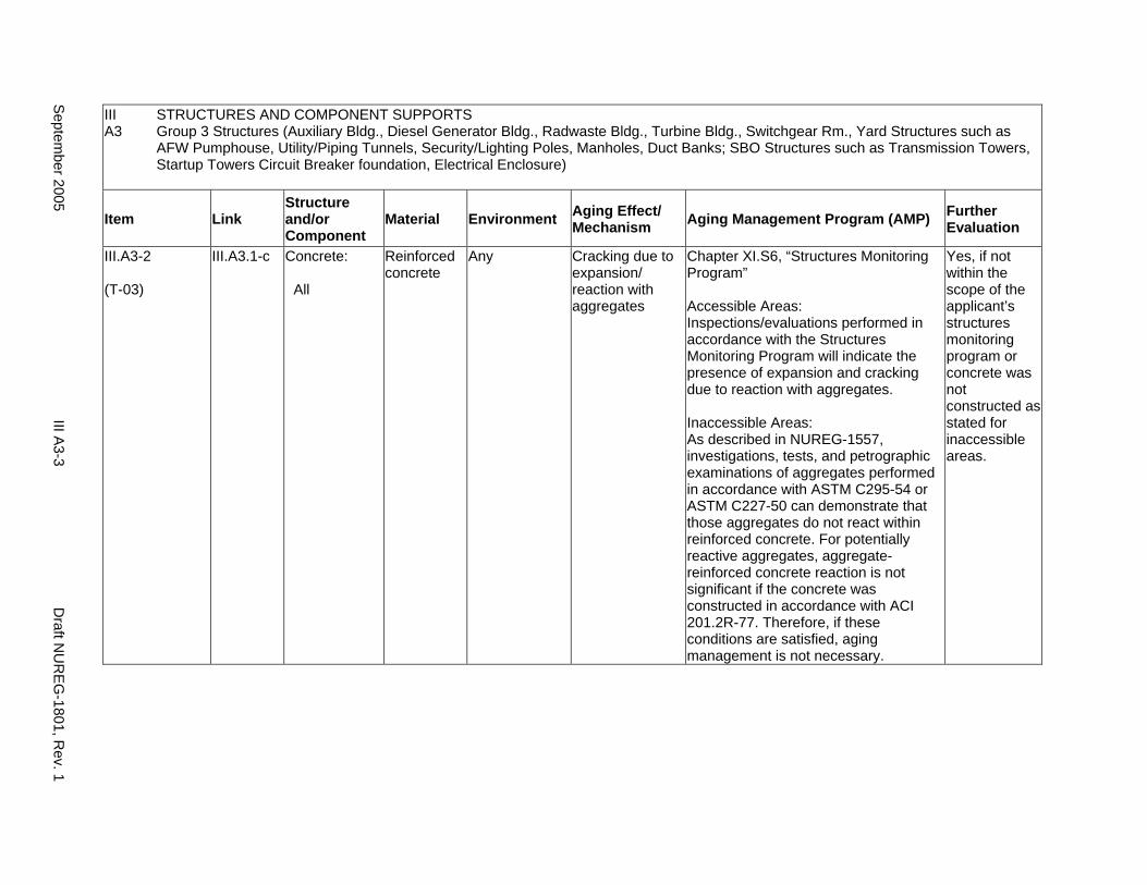
III A3
STRUCTURES AND COMPONENT SUPPORTS Group 3 Structures (Auxiliary Bldg., Diesel Generator Bldg., Radwaste Bldg., Turbine Bldg., Switchgear Rm., Yard Structures such as AFW Pumphouse, Utility/Piping Tunnels, Security/Lighting Poles, Manholes, Duct Banks; SBO Structures such as Transmission Towers, Startup Towers Circuit Breaker foundation, Electrical Enclosure)
Item Link Structure and/or Component
Material Environment Aging Effect/ Mechanism Aging Management Program (AMP) Further
Evaluation
III.A3-2
(T-03)
III.A3.1-c Concrete:
All
Reinforced concrete
Any Cracking due to expansion/ reaction with aggregates
Chapter XI.S6, “Structures Monitoring Program”
Accessible Areas: Inspections/evaluations performed in accordance with the Structures Monitoring Program will indicate the presence of expansion and cracking due to reaction with aggregates.
Inaccessible Areas: As described in NUREG-1557, investigations, tests, and petrographic examinations of aggregates performed in accordance with ASTM C295-54 or ASTM C227-50 can demonstrate that those aggregates do not react within reinforced concrete. For potentially reactive aggregates, aggregate-reinforced concrete reaction is not significant if the concrete was constructed in accordance with ACI 201.2R-77. Therefore, if these conditions are satisfied, aging management is not necessary.
Yes, if not within the scope of the applicant’s structures monitoring program or concrete was not constructed as stated for inaccessible areas.
Septem
ber 2005 III A
3-3 D
raft NU
REG
-1801, Rev. 1
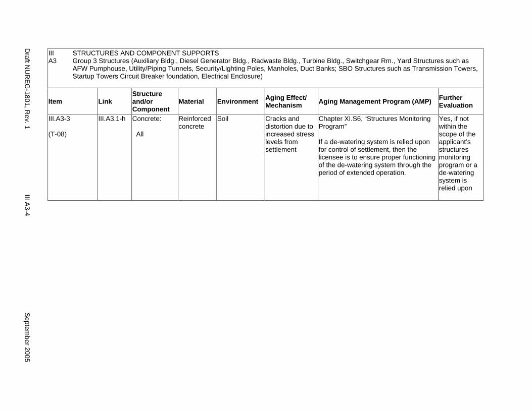
III A3
STRUCTURES AND COMPONENT SUPPORTS Group 3 Structures (Auxiliary Bldg., Diesel Generator Bldg., Radwaste Bldg., Turbine Bldg., Switchgear Rm., Yard Structures such as AFW Pumphouse, Utility/Piping Tunnels, Security/Lighting Poles, Manholes, Duct Banks; SBO Structures such as Transmission Towers, Startup Towers Circuit Breaker foundation, Electrical Enclosure)
Item Link Structure and/or Component
Material Environment Aging Effect/ Mechanism Aging Management Program (AMP) Further
Evaluation
III.A3-3
(T-08)
III.A3.1-h Concrete:
All
Reinforced concrete
Soil Cracks and distortion due to increased stress levels from settlement
Chapter XI.S6, “Structures Monitoring Program”
If a de-watering system is relied upon for control of settlement, then the licensee is to ensure proper functioning of the de-watering system through the period of extended operation.
Yes, if not within the scope of the applicant’s structures monitoring program or a de-watering system is relied upon
Draft N
UR
EG-1801, R
ev. 1 III A
3-4 S
eptember 2005
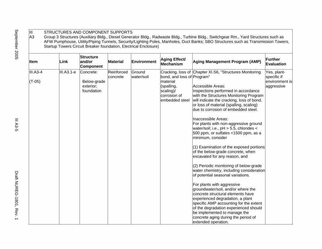
III A3
STRUCTURES AND COMPONENT SUPPORTS Group 3 Structures (Auxiliary Bldg., Diesel Generator Bldg., Radwaste Bldg., Turbine Bldg., Switchgear Rm., Yard Structures such as AFW Pumphouse, Utility/Piping Tunnels, Security/Lighting Poles, Manholes, Duct Banks; SBO Structures such as Transmission Towers, Startup Towers Circuit Breaker foundation, Electrical Enclosure)
Item Link Structure and/or Component
Material Environment Aging Effect/ Mechanism Aging Management Program (AMP) Further
Evaluation
III.A3-4
(T-05)
III.A3.1-e Concrete:
Below-grade exterior; foundation
Reinforced concrete
Ground water/soil
Cracking, loss of bond, and loss of material (spalling, scaling)/ corrosion of embedded steel
Chapter XI.S6, "Structures Monitoring Program"
Accessible Areas: Inspections performed in accordance with the Structures Monitoring Program will indicate the cracking, loss of bond, or loss of material (spalling, scaling) due to corrosion of embedded steel.
Inaccessible Areas: For plants with non-aggressive ground water/soil; i.e., pH > 5.5, chlorides < 500 ppm, or sulfates <1500 ppm, as a minimum, consider
(1) Examination of the exposed portions of the below-grade concrete, when excavated for any reason, and
(2) Periodic monitoring of below-grade water chemistry, including consideration of potential seasonal variations.
For plants with aggressive groundwater/soil, and/or where the concrete structural elements have experienced degradation, a plant specific AMP accounting for the extent of the degradation experienced should be implemented to manage the concrete aging during the period of extended operation.
Yes, plant-specific if environment is aggressive
Septem
ber 2005 III A
3-5 D
raft NU
REG
-1801, Rev. 1
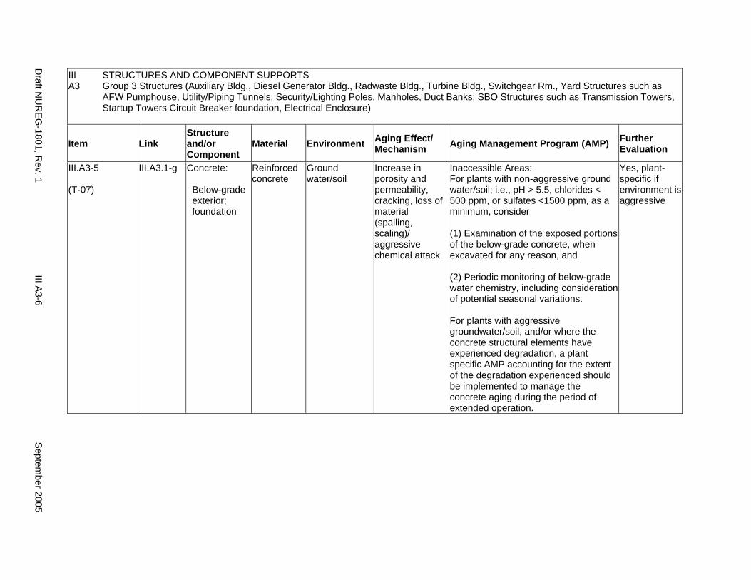
III A3
STRUCTURES AND COMPONENT SUPPORTS Group 3 Structures (Auxiliary Bldg., Diesel Generator Bldg., Radwaste Bldg., Turbine Bldg., Switchgear Rm., Yard Structures such as AFW Pumphouse, Utility/Piping Tunnels, Security/Lighting Poles, Manholes, Duct Banks; SBO Structures such as Transmission Towers, Startup Towers Circuit Breaker foundation, Electrical Enclosure)
Item Link Structure and/or Component
Material Environment Aging Effect/ Mechanism Aging Management Program (AMP) Further
Evaluation
III.A3-5
(T-07)
III.A3.1-g Concrete:
Below-grade exterior; foundation
Reinforced concrete
Ground water/soil
Increase in porosity and permeability, cracking, loss of material (spalling, scaling)/ aggressive chemical attack
Inaccessible Areas: For plants with non-aggressive ground water/soil; i.e., pH > 5.5, chlorides < 500 ppm, or sulfates <1500 ppm, as a minimum, consider
(1) Examination of the exposed portions of the below-grade concrete, when excavated for any reason, and
(2) Periodic monitoring of below-grade water chemistry, including consideration of potential seasonal variations.
For plants with aggressive groundwater/soil, and/or where the concrete structural elements have experienced degradation, a plant specific AMP accounting for the extent of the degradation experienced should be implemented to manage the concrete aging during the period of extended operation.
Yes, plant-specific if environment is aggressive
Draft N
UR
EG-1801, R
ev. 1 III A
3-6 S
eptember 2005
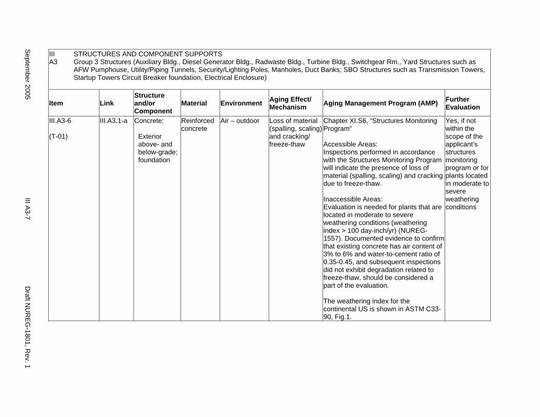
III A3
STRUCTURES AND COMPONENT SUPPORTS Group 3 Structures (Auxiliary Bldg., Diesel Generator Bldg., Radwaste Bldg., Turbine Bldg., Switchgear Rm., Yard Structures such as AFW Pumphouse, Utility/Piping Tunnels, Security/Lighting Poles, Manholes, Duct Banks; SBO Structures such as Transmission Towers, Startup Towers Circuit Breaker foundation, Electrical Enclosure)
Item Link Structure and/or Component
Material Environment Aging Effect/ Mechanism Aging Management Program (AMP) Further
Evaluation
III.A3-6
(T-01)
III.A3.1-a Concrete:
Exterior above- and below-grade; foundation
Reinforced concrete
Air – outdoor Loss of material (spalling, scaling) and cracking/ freeze-thaw
Chapter XI.S6, “Structures Monitoring Program”
Accessible Areas: Inspections performed in accordance with the Structures Monitoring Program will indicate the presence of loss of material (spalling, scaling) and cracking due to freeze-thaw.
Inaccessible Areas: Evaluation is needed for plants that are located in moderate to severe weathering conditions (weathering index > 100 day-inch/yr) (NUREG1557). Documented evidence to confirm that existing concrete has air content of 3% to 6% and water-to-cement ratio of 0.35-0.45, and subsequent inspections did not exhibit degradation related to freeze-thaw, should be considered a part of the evaluation.
The weathering index for the continental US is shown in ASTM C3390, Fig.1.
Yes, if not within the scope of the applicant’s structures monitoring program or for plants located in moderate to severe weathering conditions
Septem
ber 2005 III A
3-7 D
raft NU
REG
-1801, Rev. 1
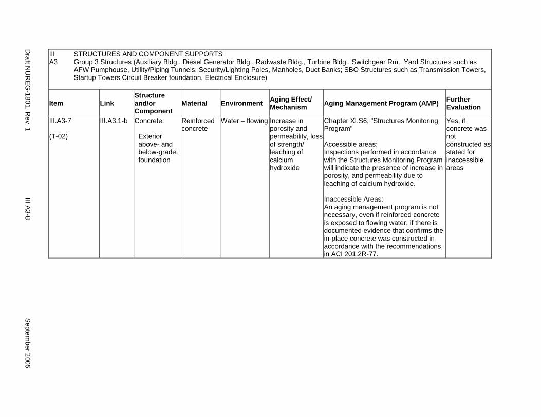
III A3
STRUCTURES AND COMPONENT SUPPORTS Group 3 Structures (Auxiliary Bldg., Diesel Generator Bldg., Radwaste Bldg., Turbine Bldg., Switchgear Rm., Yard Structures such as AFW Pumphouse, Utility/Piping Tunnels, Security/Lighting Poles, Manholes, Duct Banks; SBO Structures such as Transmission Towers, Startup Towers Circuit Breaker foundation, Electrical Enclosure)
Item Link Structure and/or Component
Material Environment Aging Effect/ Mechanism Aging Management Program (AMP) Further
Evaluation
III.A3-7
(T-02)
III.A3.1-b Concrete:
Exterior above- and below-grade; foundation
Reinforced concrete
Water – flowing Increase in porosity and permeability, loss of strength/ leaching of calcium hydroxide
Chapter XI.S6, "Structures Monitoring Program"
Accessible areas: Inspections performed in accordance with the Structures Monitoring Program will indicate the presence of increase in porosity, and permeability due to leaching of calcium hydroxide.
Inaccessible Areas: An aging management program is not necessary, even if reinforced concrete is exposed to flowing water, if there is documented evidence that confirms the in-place concrete was constructed in accordance with the recommendations in ACI 201.2R-77.
Yes, if concrete was not constructed as stated for inaccessible areas
Draft N
UR
EG-1801, R
ev. 1 III A
3-8 S
eptember 2005
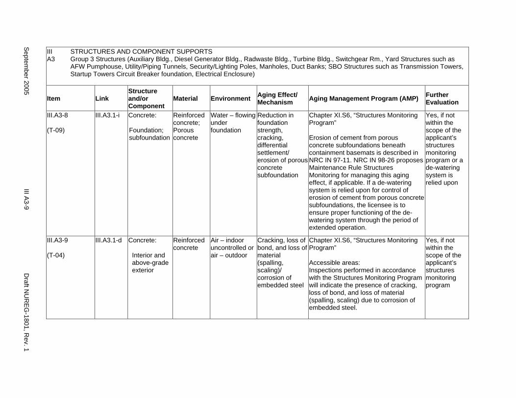
III A3
STRUCTURES AND COMPONENT SUPPORTS Group 3 Structures (Auxiliary Bldg., Diesel Generator Bldg., Radwaste Bldg., Turbine Bldg., Switchgear Rm., Yard Structures such as AFW Pumphouse, Utility/Piping Tunnels, Security/Lighting Poles, Manholes, Duct Banks; SBO Structures such as Transmission Towers, Startup Towers Circuit Breaker foundation, Electrical Enclosure)
Item Link Structure and/or Component
Material Environment Aging Effect/ Mechanism Aging Management Program (AMP) Further
Evaluation
III.A3-8
(T-09)
III.A3.1-i Concrete:
Foundation; subfoundation
Reinforced concrete; Porous concrete
Water – flowing under foundation
Reduction in foundation strength, cracking, differential settlement/ erosion of porous concrete subfoundation
Chapter XI.S6, “Structures Monitoring Program”
Erosion of cement from porous concrete subfoundations beneath containment basemats is described in NRC IN 97-11. NRC IN 98-26 proposes Maintenance Rule Structures Monitoring for managing this aging effect, if applicable. If a de-watering system is relied upon for control of erosion of cement from porous concrete subfoundations, the licensee is to ensure proper functioning of the dewatering system through the period of extended operation.
Yes, if not within the scope of the applicant’s structures monitoring program or a de-watering system is relied upon
III.A3-9
(T-04)
III.A3.1-d Concrete:
Interior and above-grade exterior
Reinforced concrete
Air – indoor uncontrolled or air – outdoor
Cracking, loss of bond, and loss of material (spalling, scaling)/ corrosion of embedded steel
Chapter XI.S6, “Structures Monitoring Program”
Accessible areas: Inspections performed in accordance with the Structures Monitoring Program will indicate the presence of cracking, loss of bond, and loss of material (spalling, scaling) due to corrosion of embedded steel.
Yes, if not within the scope of the applicant’s structures monitoring program
Septem
ber 2005 III A
3-9 D
raft NU
REG
-1801, Rev. 1
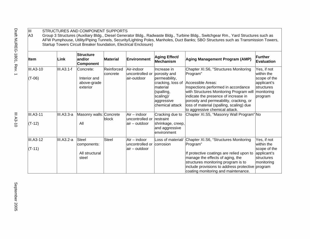
III STRUCTURES AND COMPONENT SUPPORTS A3 Group 3 Structures (Auxiliary Bldg., Diesel Generator Bldg., Radwaste Bldg., Turbine Bldg., Switchgear Rm., Yard Structures such as
AFW Pumphouse, Utility/Piping Tunnels, Security/Lighting Poles, Manholes, Duct Banks; SBO Structures such as Transmission Towers, Startup Towers Circuit Breaker foundation, Electrical Enclosure)
Item Link Structure and/or Component
Material Environment Aging Effect/ Mechanism Aging Management Program (AMP) Further
Evaluation
III.A3-10
(T-06)
III.A3.1-f Concrete:
Interior and above-grade exterior
Reinforced concrete
Air-indoor uncontrolled or air-outdoor
Increase in porosity and permeability, cracking, loss of material (spalling, scaling)/ aggressive chemical attack
Chapter XI.S6, "Structures Monitoring Program"
Accessible Areas: Inspections performed in accordance with Structures Monitoring Program will indicate the presence of increase in porosity and permeability, cracking, or loss of material (spalling, scaling) due to aggressive chemical attack.
Yes, if not within the scope of the applicant’s structures monitoring program
III.A3-11
(T-12)
III.A3.3-a Masonry walls:
All
Concrete block
Air – indoor uncontrolled or air – outdoor
Cracking due to restraint shrinkage, creep, and aggressive environment
Chapter XI.S5, “Masonry Wall Program” No
III.A3-12
(T-11)
III.A3.2-a Steel components:
All structural steel
Steel Air – indoor uncontrolled or air – outdoor
Loss of material/ corrosion
Chapter XI.S6, “Structures Monitoring Program”
If protective coatings are relied upon to manage the effects of aging, the structures monitoring program is to include provisions to address protective coating monitoring and maintenance.
Yes, if not within the scope of the applicant’s structures monitoring program
Draft N
UR
EG-1801, R
ev. 1 III A
3-10 S
eptember 2005
A4. GROUP 4 STRUCTURES (CONTAINMENT INTERNAL STRUCTURES, EXCLUDING REFUELING CANAL)
Systems, Structures, and Components
This section addresses the elements of containment internal structures, excluding refueling canal. For this group, the applicable structural elements are identified: concrete and steel elements. The aging management review is presented for each applicable combination of structural element and aging effect.
System Interfaces
Physical interfaces exist with any system or component that either penetrates the structure wall or is supported by the structure wall, floor, and roof. The direct interface is through the system or component supports that are anchored to the structure. Structures also protect housed systems and components from internal and external design basis events. In the case of tanks, there is a functional interface with the associated system. Water-control structures are integral parts of the systems that provide plant cooling water and residual heat removal.
September 2005 III A4-1 Draft NUREG-1801, Rev. 1
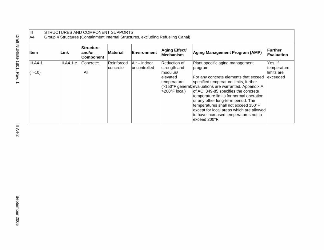
III A4
STRUCTURES AND COMPONENT SUPPORTS Group 4 Structures (Containment Internal Structures, excluding Refueling Canal)
Item Link Structure and/or Component
Material Environment Aging Effect/ Mechanism Aging Management Program (AMP) Further
Evaluation
III.A4-1
(T-10)
III.A4.1-c Concrete:
All
Reinforced concrete
Air – indoor uncontrolled
Reduction of strength and modulus/ elevated temperature (>150°F general; >200°F local)
Plant-specific aging management program
For any concrete elements that exceed specified temperature limits, further evaluations are warranted. Appendix A of ACI 349-85 specifies the concrete temperature limits for normal operation or any other long-term period. The temperatures shall not exceed 150°F except for local areas which are allowed to have increased temperatures not to exceed 200°F.
Yes, if temperature limits are exceeded
Draft N
UR
EG-1801, R
ev. 1 III A
4-2 S
eptember 2005
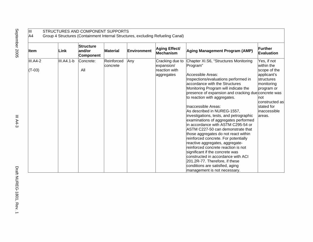
III STRUCTURES AND COMPONENT SUPPORTS A4 Group 4 Structures (Containment Internal Structures, excluding Refueling Canal)
Item Link Structure and/or Component
Material Environment Aging Effect/ Mechanism Aging Management Program (AMP) Further
Evaluation
III.A4-2
(T-03)
III.A4.1-b Concrete:
All
Reinforced concrete
Any Cracking due to expansion/ reaction with aggregates
Chapter XI.S6, “Structures Monitoring Program”
Accessible Areas: Inspections/evaluations performed in accordance with the Structures Monitoring Program will indicate the presence of expansion and cracking due to reaction with aggregates.
Inaccessible Areas: As described in NUREG-1557, investigations, tests, and petrographic examinations of aggregates performed in accordance with ASTM C295-54 or ASTM C227-50 can demonstrate that those aggregates do not react within reinforced concrete. For potentially reactive aggregates, aggregate-reinforced concrete reaction is not significant if the concrete was constructed in accordance with ACI 201.2R-77. Therefore, if these conditions are satisfied, aging management is not necessary.
Yes, if not within the scope of the applicant’s structures monitoring program or concrete was not constructed as stated for inaccessible areas.
Septem
ber 2005 III A
4-3 D
raft NU
REG
-1801, Rev. 1
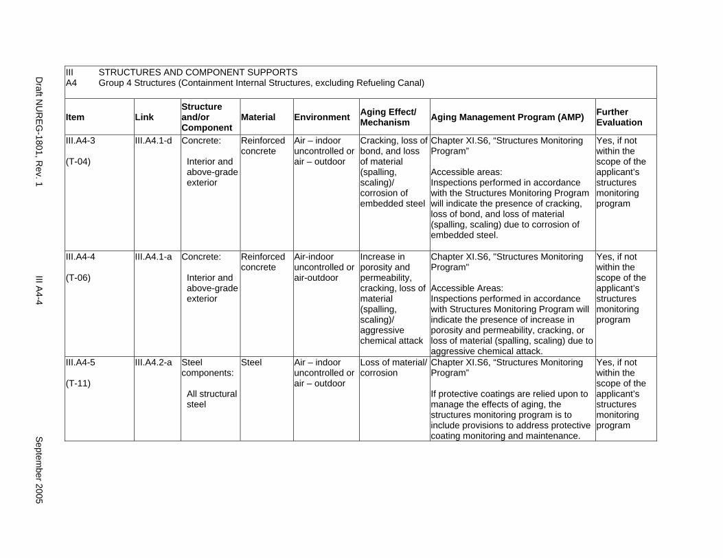
III A4
STRUCTURES AND COMPONENT SUPPORTS Group 4 Structures (Containment Internal Structures, excluding Refueling Canal)
Item Link Structure and/or Component
Material Environment Aging Effect/ Mechanism Aging Management Program (AMP) Further
Evaluation
III.A4-3
(T-04)
III.A4.1-d Concrete:
Interior and above-grade exterior
Reinforced concrete
Air – indoor uncontrolled or air – outdoor
Cracking, loss of bond, and loss of material (spalling, scaling)/ corrosion of embedded steel
Chapter XI.S6, “Structures Monitoring Program”
Accessible areas: Inspections performed in accordance with the Structures Monitoring Program will indicate the presence of cracking, loss of bond, and loss of material (spalling, scaling) due to corrosion of embedded steel.
Yes, if not within the scope of the applicant’s structures monitoring program
III.A4-4
(T-06)
III.A4.1-a Concrete:
Interior and above-grade exterior
Reinforced concrete
Air-indoor uncontrolled or air-outdoor
Increase in porosity and permeability, cracking, loss of material (spalling, scaling)/ aggressive chemical attack
Chapter XI.S6, "Structures Monitoring Program"
Accessible Areas: Inspections performed in accordance with Structures Monitoring Program will indicate the presence of increase in porosity and permeability, cracking, or loss of material (spalling, scaling) due to aggressive chemical attack.
Yes, if not within the scope of the applicant’s structures monitoring program
III.A4-5
(T-11)
III.A4.2-a Steel components:
All structural steel
Steel Air – indoor uncontrolled or air – outdoor
Loss of material/ corrosion
Chapter XI.S6, “Structures Monitoring Program”
If protective coatings are relied upon to manage the effects of aging, the structures monitoring program is to include provisions to address protective coating monitoring and maintenance.
Yes, if not within the scope of the applicant’s structures monitoring program
Draft N
UR
EG-1801, R
ev. 1 III A
4-4 S
eptember 2005
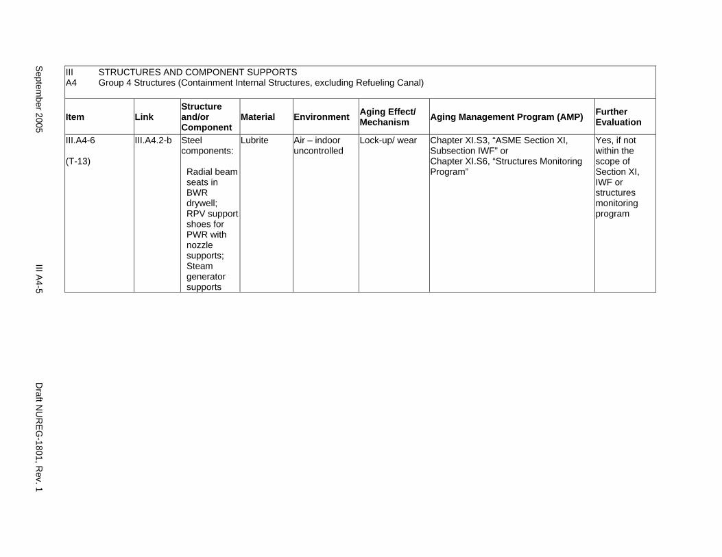
III STRUCTURES AND COMPONENT SUPPORTS A4 Group 4 Structures (Containment Internal Structures, excluding Refueling Canal)
Item Link Structure and/or Component
Material Environment Aging Effect/ Mechanism Aging Management Program (AMP) Further
Evaluation
III.A4-6
(T-13)
III.A4.2-b Steel components:
Radial beam seats in BWR drywell; RPV support shoes for PWR with nozzle supports; Steam generator supports
Lubrite Air – indoor uncontrolled
Lock-up/ wear Chapter XI.S3, “ASME Section XI, Subsection IWF” or Chapter XI.S6, “Structures Monitoring Program”
Yes, if not within the scope of Section XI, IWF or structures monitoring program
Septem
ber 2005 III A
4-5 D
raft NU
REG
-1801, Rev. 1

This Page Intentionally Left Blank
Draft NUREG-1801, Rev. 1 III A4-6 September 2005
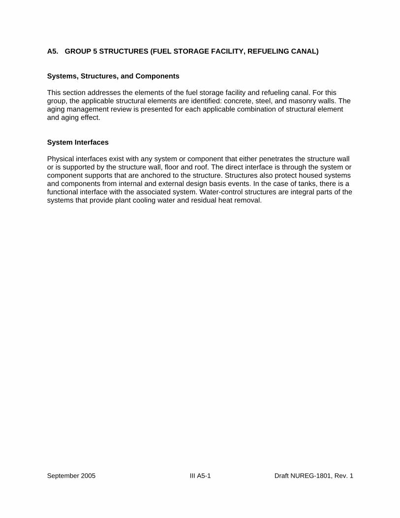
A5. GROUP 5 STRUCTURES (FUEL STORAGE FACILITY, REFUELING CANAL)
Systems, Structures, and Components
This section addresses the elements of the fuel storage facility and refueling canal. For this group, the applicable structural elements are identified: concrete, steel, and masonry walls. The aging management review is presented for each applicable combination of structural element and aging effect.
System Interfaces
Physical interfaces exist with any system or component that either penetrates the structure wall or is supported by the structure wall, floor and roof. The direct interface is through the system or component supports that are anchored to the structure. Structures also protect housed systems and components from internal and external design basis events. In the case of tanks, there is a functional interface with the associated system. Water-control structures are integral parts of the systems that provide plant cooling water and residual heat removal.
September 2005 III A5-1 Draft NUREG-1801, Rev. 1

III STRUCTURES AND COMPONENT SUPPORTS A5 Group 5 Structures (Fuel Storage Facility, Refueling Canal)
Item Link Structure and/or Component
Material Environment Aging Effect/ Mechanism Aging Management Program (AMP) Further
Evaluation
III.A5-1
(T-10)
III.A5.1-j Concrete:
All
Reinforced concrete
Air – indoor uncontrolled
Reduction of strength and modulus/ elevated temperature (>150°F general; >200°F local)
Plant-specific aging management program
For any concrete elements that exceed specified temperature limits, further evaluations are warranted. Appendix A of ACI 349-85 specifies the concrete temperature limits for normal operation or any other long-term period. The temperatures shall not exceed 150°F except for local areas which are allowed to have increased temperatures not to exceed 200°F.
Yes, if temperature limits are exceeded
Draft N
UR
EG-1801, R
ev. 1 III A
5-2 S
eptember 2005
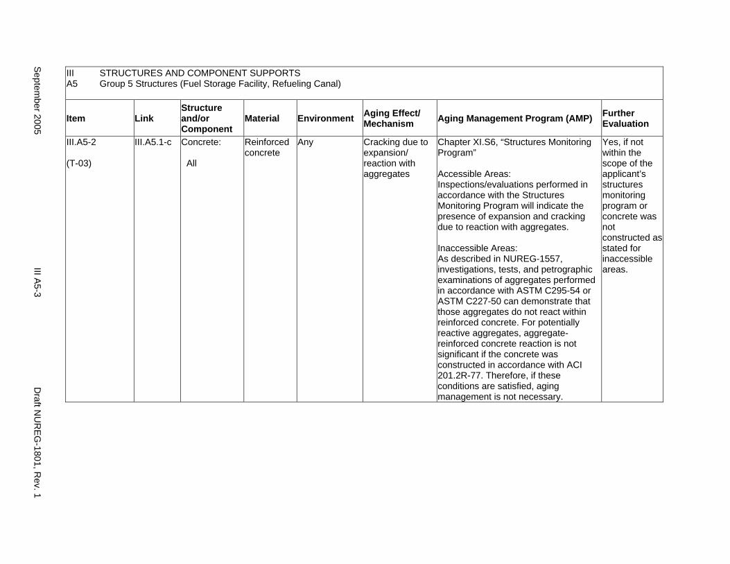
III STRUCTURES AND COMPONENT SUPPORTS A5 Group 5 Structures (Fuel Storage Facility, Refueling Canal)
Item Link Structure and/or Component
Material Environment Aging Effect/ Mechanism Aging Management Program (AMP) Further
Evaluation
III.A5-2
(T-03)
III.A5.1-c Concrete:
All
Reinforced concrete
Any Cracking due to expansion/ reaction with aggregates
Chapter XI.S6, “Structures Monitoring Program”
Accessible Areas: Inspections/evaluations performed in accordance with the Structures Monitoring Program will indicate the presence of expansion and cracking due to reaction with aggregates.
Inaccessible Areas: As described in NUREG-1557, investigations, tests, and petrographic examinations of aggregates performed in accordance with ASTM C295-54 or ASTM C227-50 can demonstrate that those aggregates do not react within reinforced concrete. For potentially reactive aggregates, aggregate-reinforced concrete reaction is not significant if the concrete was constructed in accordance with ACI 201.2R-77. Therefore, if these conditions are satisfied, aging management is not necessary.
Yes, if not within the scope of the applicant’s structures monitoring program or concrete was not constructed as stated for inaccessible areas.
Septem
ber 2005 III A
5-3 D
raft NU
REG
-1801, Rev. 1
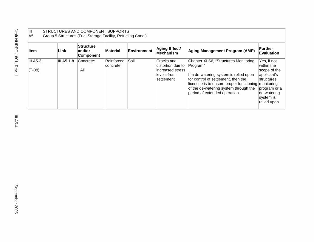
III STRUCTURES AND COMPONENT SUPPORTS A5 Group 5 Structures (Fuel Storage Facility, Refueling Canal)
Item Link Structure and/or Component
Material Environment Aging Effect/ Mechanism Aging Management Program (AMP) Further
Evaluation
III.A5-3
(T-08)
III.A5.1-h Concrete:
All
Reinforced concrete
Soil Cracks and distortion due to increased stress levels from settlement
Chapter XI.S6, “Structures Monitoring Program”
If a de-watering system is relied upon for control of settlement, then the licensee is to ensure proper functioning of the de-watering system through the period of extended operation.
Yes, if not within the scope of the applicant’s structures monitoring program or a de-watering system is relied upon
Draft N
UR
EG-1801, R
ev. 1 III A
5-4 S
eptember 2005
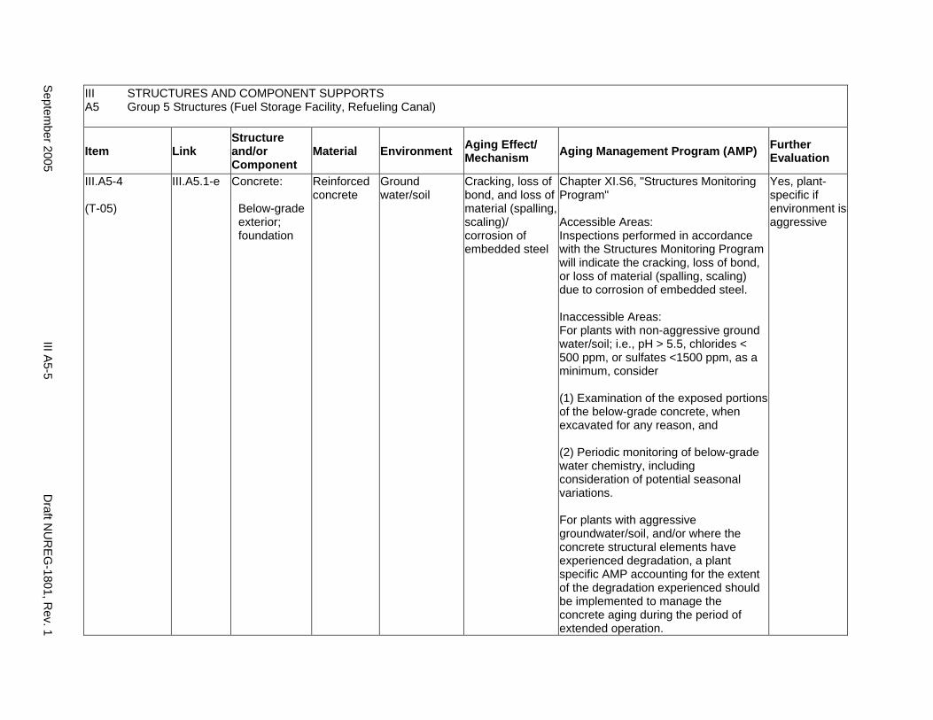
III STRUCTURES AND COMPONENT SUPPORTS A5 Group 5 Structures (Fuel Storage Facility, Refueling Canal)
Item Link Structure and/or Component
Material Environment Aging Effect/ Mechanism Aging Management Program (AMP) Further
Evaluation
III.A5-4
(T-05)
III.A5.1-e Concrete:
Below-grade exterior; foundation
Reinforced concrete
Ground water/soil
Cracking, loss of bond, and loss of material (spalling, scaling)/ corrosion of embedded steel
Chapter XI.S6, "Structures Monitoring Program"
Accessible Areas: Inspections performed in accordance with the Structures Monitoring Program will indicate the cracking, loss of bond, or loss of material (spalling, scaling) due to corrosion of embedded steel.
Inaccessible Areas: For plants with non-aggressive ground water/soil; i.e., pH > 5.5, chlorides < 500 ppm, or sulfates <1500 ppm, as a minimum, consider
(1) Examination of the exposed portions of the below-grade concrete, when excavated for any reason, and
(2) Periodic monitoring of below-grade water chemistry, including consideration of potential seasonal variations.
For plants with aggressive groundwater/soil, and/or where the concrete structural elements have experienced degradation, a plant specific AMP accounting for the extent of the degradation experienced should be implemented to manage the concrete aging during the period of extended operation.
Yes, plant-specific if environment is aggressive
Septem
ber 2005 III A
5-5 D
raft NU
REG
-1801, Rev. 1
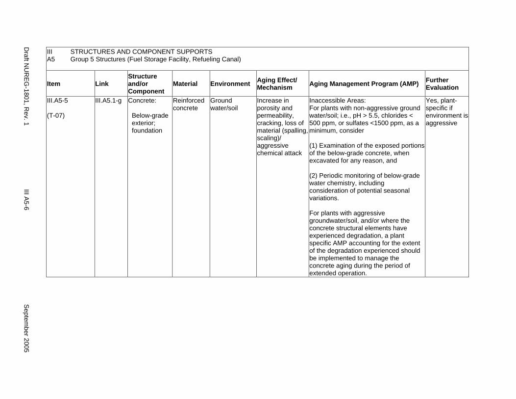
III STRUCTURES AND COMPONENT SUPPORTS A5 Group 5 Structures (Fuel Storage Facility, Refueling Canal)
Item Link Structure and/or Component
Material Environment Aging Effect/ Mechanism Aging Management Program (AMP) Further
Evaluation
III.A5-5
(T-07)
III.A5.1-g Concrete:
Below-grade exterior; foundation
Reinforced concrete
Ground water/soil
Increase in porosity and permeability, cracking, loss of material (spalling, scaling)/ aggressive chemical attack
Inaccessible Areas: For plants with non-aggressive ground water/soil; i.e., pH > 5.5, chlorides < 500 ppm, or sulfates <1500 ppm, as a minimum, consider
(1) Examination of the exposed portions of the below-grade concrete, when excavated for any reason, and
(2) Periodic monitoring of below-grade water chemistry, including consideration of potential seasonal variations.
For plants with aggressive groundwater/soil, and/or where the concrete structural elements have experienced degradation, a plant specific AMP accounting for the extent of the degradation experienced should be implemented to manage the concrete aging during the period of extended operation.
Yes, plant-specific if environment is aggressive
Draft N
UR
EG-1801, R
ev. 1 III A
5-6 S
eptember 2005
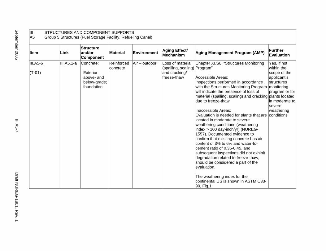
III STRUCTURES AND COMPONENT SUPPORTS A5 Group 5 Structures (Fuel Storage Facility, Refueling Canal)
Item Link Structure and/or Component
Material Environment Aging Effect/ Mechanism Aging Management Program (AMP) Further
Evaluation
III.A5-6
(T-01)
III.A5.1-a Concrete:
Exterior above- and below-grade; foundation
Reinforced concrete
Air – outdoor Loss of material (spalling, scaling) and cracking/ freeze-thaw
Chapter XI.S6, “Structures Monitoring Program”
Accessible Areas: Inspections performed in accordance with the Structures Monitoring Program will indicate the presence of loss of material (spalling, scaling) and cracking due to freeze-thaw.
Inaccessible Areas: Evaluation is needed for plants that are located in moderate to severe weathering conditions (weathering index > 100 day-inch/yr) (NUREG1557). Documented evidence to confirm that existing concrete has air content of 3% to 6% and water-tocement ratio of 0.35-0.45, and subsequent inspections did not exhibit degradation related to freeze-thaw, should be considered a part of the evaluation.
The weathering index for the continental US is shown in ASTM C3390, Fig.1.
Yes, if not within the scope of the applicant’s structures monitoring program or for plants located in moderate to severe weathering conditions
Septem
ber 2005 III A
5-7 D
raft NU
REG
-1801, Rev. 1

III A5
STRUCTURES AND COMPONENT SUPPORTS Group 5 Structures (Fuel Storage Facility, Refueling Canal)
Item Link Structure and/or Component
Material Environment Aging Effect/ Mechanism Aging Management Program (AMP) Further
Evaluation
III.A5-7
(T-02)
III.A5.1-b Concrete:
Exterior above- and below-grade; foundation
Reinforced concrete
Water – flowing Increase in porosity and permeability, loss of strength/ leaching of calcium hydroxide
Chapter XI.S6, "Structures Monitoring Program"
Accessible areas: Inspections performed in accordance with the Structures Monitoring Program will indicate the presence of increased porosity, and permeability due to leaching of calcium hydroxide.
Inaccessible Areas: An aging management program is not necessary, even if reinforced concrete is exposed to flowing water, if there is documented evidence that confirms the in-place concrete was constructed in accordance with the recommendations in ACI 201.2R-77.
Yes, if concrete was not constructed as stated for inaccessible areas
Draft N
UR
EG-1801, R
ev. 1 III A
5-8 S
eptember 2005
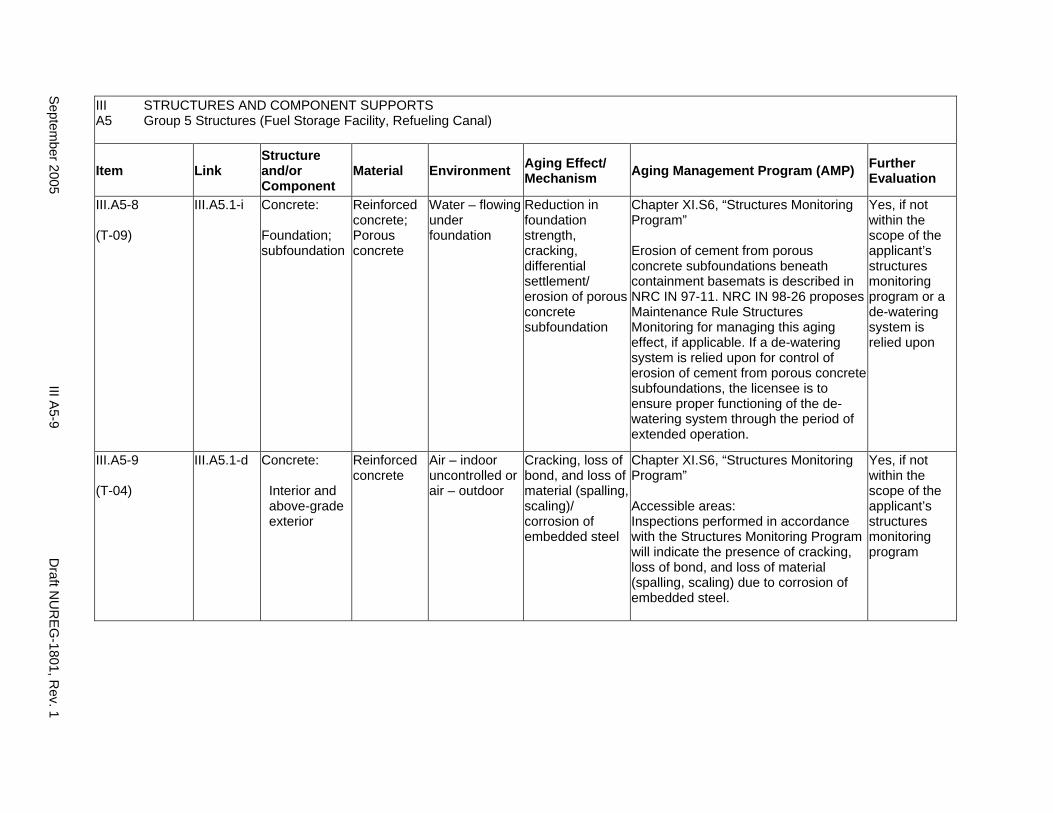
III A5
STRUCTURES AND COMPONENT SUPPORTS Group 5 Structures (Fuel Storage Facility, Refueling Canal)
Item Link Structure and/or Component
Material Environment Aging Effect/ Mechanism Aging Management Program (AMP) Further
Evaluation
III.A5-8
(T-09)
III.A5.1-i Concrete:
Foundation; subfoundation
Reinforced concrete; Porous concrete
Water – flowing under foundation
Reduction in foundation strength, cracking, differential settlement/ erosion of porous concrete subfoundation
Chapter XI.S6, “Structures Monitoring Program”
Erosion of cement from porous concrete subfoundations beneath containment basemats is described in NRC IN 97-11. NRC IN 98-26 proposes Maintenance Rule Structures Monitoring for managing this aging effect, if applicable. If a de-watering system is relied upon for control of erosion of cement from porous concrete subfoundations, the licensee is to ensure proper functioning of the dewatering system through the period of extended operation.
Yes, if not within the scope of the applicant’s structures monitoring program or a de-watering system is relied upon
III.A5-9
(T-04)
III.A5.1-d Concrete:
Interior and above-grade exterior
Reinforced concrete
Air – indoor uncontrolled or air – outdoor
Cracking, loss of bond, and loss of material (spalling, scaling)/ corrosion of embedded steel
Chapter XI.S6, “Structures Monitoring Program”
Accessible areas: Inspections performed in accordance with the Structures Monitoring Program will indicate the presence of cracking, loss of bond, and loss of material (spalling, scaling) due to corrosion of embedded steel.
Yes, if not within the scope of the applicant’s structures monitoring program
Septem
ber 2005 III A
5-9 D
raft NU
REG
-1801, Rev. 1
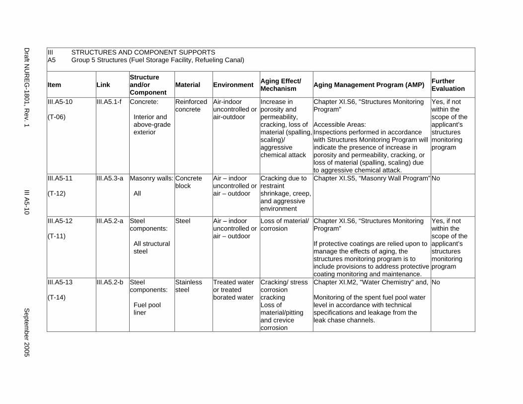
III STRUCTURES AND COMPONENT SUPPORTS A5 Group 5 Structures (Fuel Storage Facility, Refueling Canal)
Item Link Structure and/or Component
Material Environment Aging Effect/ Mechanism Aging Management Program (AMP) Further
Evaluation
III.A5-10
(T-06)
III.A5.1-f Concrete:
Interior and above-grade exterior
Reinforced concrete
Air-indoor uncontrolled or air-outdoor
Increase in porosity and permeability, cracking, loss of material (spalling, scaling)/ aggressive chemical attack
Chapter XI.S6, "Structures Monitoring Program"
Accessible Areas: Inspections performed in accordance with Structures Monitoring Program will indicate the presence of increase in porosity and permeability, cracking, or loss of material (spalling, scaling) due to aggressive chemical attack.
Yes, if not within the scope of the applicant’s structures monitoring program
III.A5-11
(T-12)
III.A5.3-a Masonry walls:
All
Concrete block
Air – indoor uncontrolled or air – outdoor
Cracking due to restraint shrinkage, creep, and aggressive environment
Chapter XI.S5, “Masonry Wall Program” No
III.A5-12
(T-11)
III.A5.2-a Steel components:
All structural steel
Steel Air – indoor uncontrolled or air – outdoor
Loss of material/ corrosion
Chapter XI.S6, “Structures Monitoring Program”
If protective coatings are relied upon to manage the effects of aging, the structures monitoring program is to include provisions to address protective coating monitoring and maintenance.
Yes, if not within the scope of the applicant’s structures monitoring program
III.A5-13
(T-14)
III.A5.2-b Steel components:
Fuel pool liner
Stainless steel
Treated water or treated borated water
Cracking/ stress corrosion cracking Loss of material/pitting and crevice corrosion
Chapter XI.M2, "Water Chemistry" and,
Monitoring of the spent fuel pool water level in accordance with technical specifications and leakage from the leak chase channels.
No
Draft N
UR
EG-1801, R
ev. 1 III A
5-10 S
eptember 2005
A6. GROUP 6 STRUCTURES (WATER-CONTROL STRUCTURES)
Systems, Structures, and Components
This section addresses the elements of water-control structures. For this group, the applicable structural elements are identified: concrete, steel, masonry walls, and earthen water-control structures. The aging management review is presented for each applicable combination of structural element and aging effect.
System Interfaces
Physical interfaces exist with any system or component that either penetrates the structure wall or is supported by the structure wall, floor, and roof. The direct interface is through the system or component supports that are anchored to the structure. Structures also protect housed systems and components from internal and external design basis events. In the case of tanks, there is a functional interface with the associated system. Water-control structures are integral parts of the systems that provide plant cooling water and residual heat removal.
September 2005 III A6-1 Draft NUREG-1801, Rev. 1
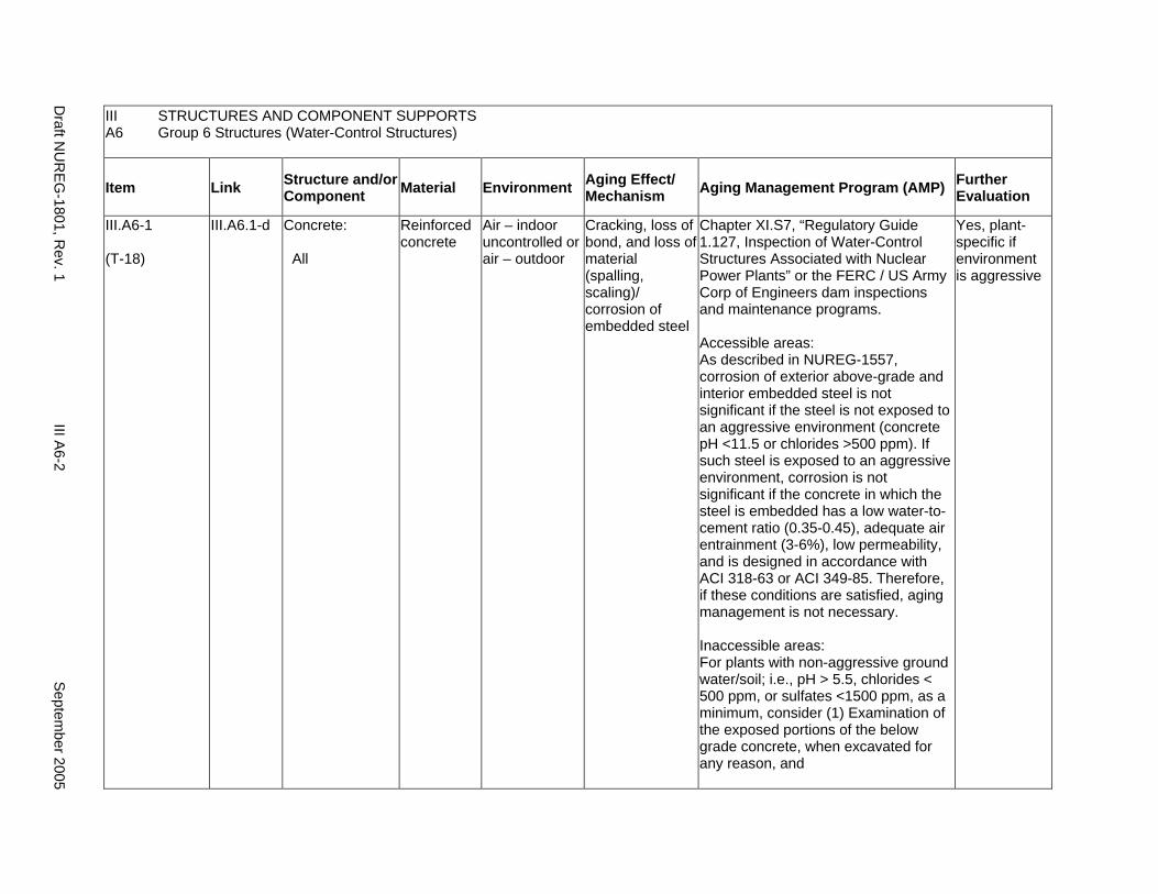
III STRUCTURES AND COMPONENT SUPPORTS A6 Group 6 Structures (Water-Control Structures)
Item Link Structure and/or Component Material Environment Aging Effect/
Mechanism Aging Management Program (AMP) Further Evaluation
III.A6-1
(T-18)
III.A6.1-d Concrete:
All
Reinforced concrete
Air – indoor uncontrolled or air – outdoor
Cracking, loss of bond, and loss of material (spalling, scaling)/ corrosion of embedded steel
Chapter XI.S7, “Regulatory Guide 1.127, Inspection of Water-Control Structures Associated with Nuclear Power Plants” or the FERC / US Army Corp of Engineers dam inspections and maintenance programs.
Accessible areas: As described in NUREG-1557, corrosion of exterior above-grade and interior embedded steel is not significant if the steel is not exposed to an aggressive environment (concrete pH <11.5 or chlorides >500 ppm). If such steel is exposed to an aggressive environment, corrosion is not significant if the concrete in which the steel is embedded has a low water-tocement ratio (0.35-0.45), adequate air entrainment (3-6%), low permeability, and is designed in accordance with ACI 318-63 or ACI 349-85. Therefore, if these conditions are satisfied, aging management is not necessary.
Inaccessible areas: For plants with non-aggressive ground water/soil; i.e., pH > 5.5, chlorides < 500 ppm, or sulfates <1500 ppm, as a minimum, consider (1) Examination of the exposed portions of the below grade concrete, when excavated for any reason, and
Yes, plant-specific if environment is aggressive
Draft N
UR
EG-1801, R
ev. 1 III A
6-2 S
eptember 2005
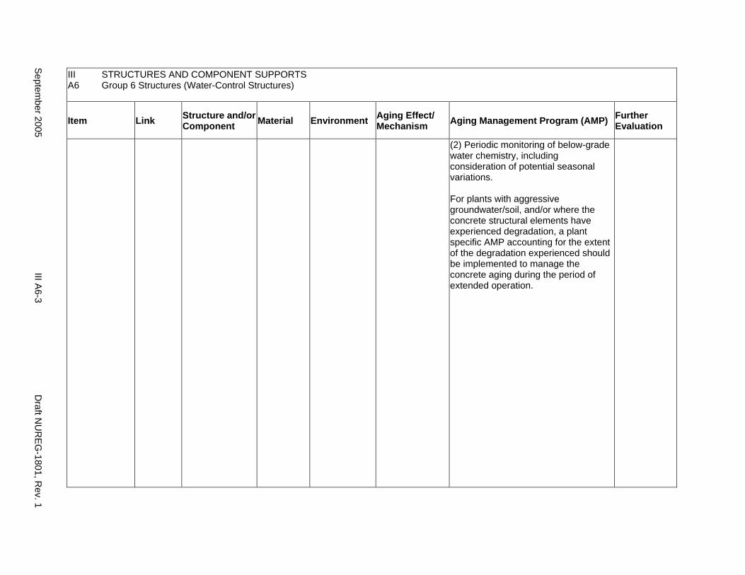
III A6
STRUCTURES AND COMPONENT SUPPORTS Group 6 Structures (Water-Control Structures)
Item Link Structure and/or Component Material Environment Aging Effect/
Mechanism Aging Management Program (AMP) Further Evaluation
(2) Periodic monitoring of below-grade water chemistry, including consideration of potential seasonal variations.
For plants with aggressive groundwater/soil, and/or where the concrete structural elements have experienced degradation, a plant specific AMP accounting for the extent of the degradation experienced should be implemented to manage the concrete aging during the period of extended operation.
Septem
ber 2005 III A
6-3 D
raft NU
REG
-1801, Rev. 1
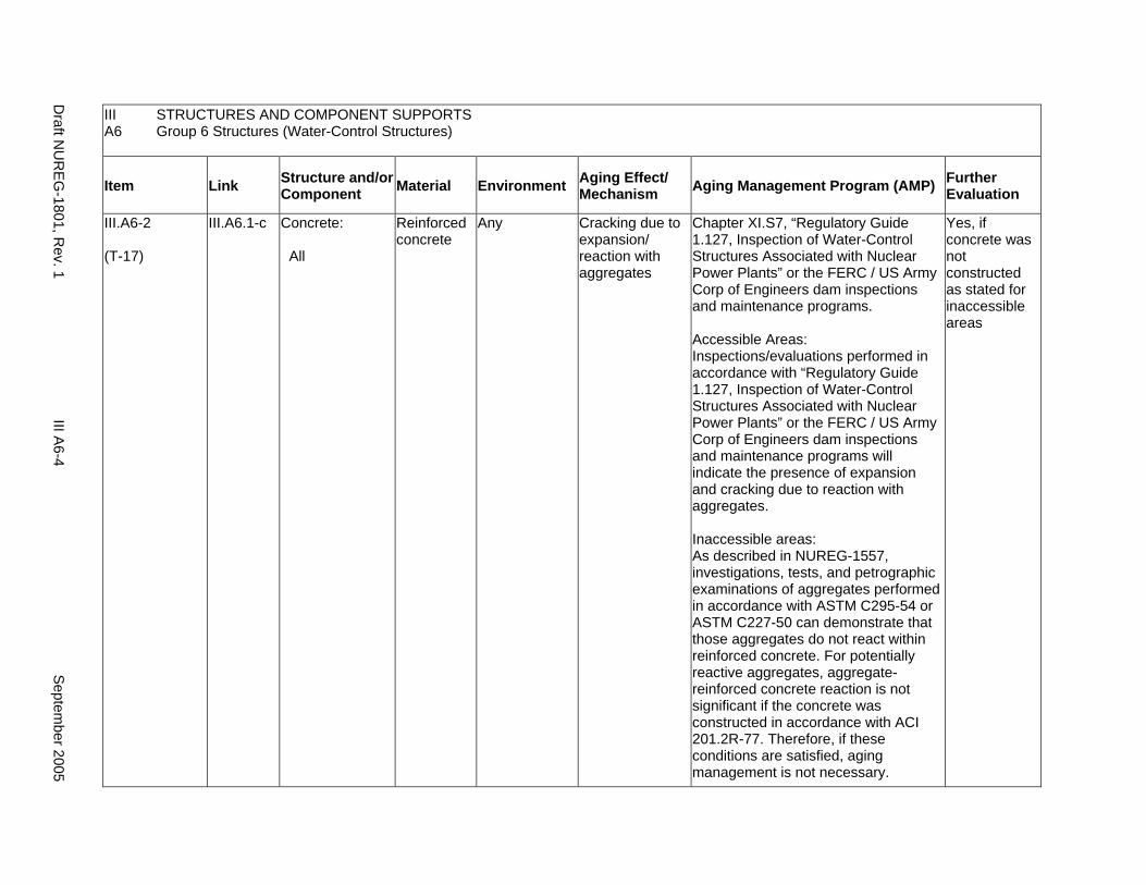
III STRUCTURES AND COMPONENT SUPPORTS A6 Group 6 Structures (Water-Control Structures)
Item Link Structure and/or Component Material Environment Aging Effect/
Mechanism Aging Management Program (AMP) Further Evaluation
III.A6-2
(T-17)
III.A6.1-c Concrete:
All
Reinforced concrete
Any Cracking due to expansion/ reaction with aggregates
Chapter XI.S7, “Regulatory Guide 1.127, Inspection of Water-Control Structures Associated with Nuclear Power Plants” or the FERC / US Army Corp of Engineers dam inspections and maintenance programs.
Accessible Areas: Inspections/evaluations performed in accordance with “Regulatory Guide 1.127, Inspection of Water-Control Structures Associated with Nuclear Power Plants” or the FERC / US Army Corp of Engineers dam inspections and maintenance programs will indicate the presence of expansion and cracking due to reaction with aggregates.
Inaccessible areas: As described in NUREG-1557, investigations, tests, and petrographic examinations of aggregates performed in accordance with ASTM C295-54 or ASTM C227-50 can demonstrate that those aggregates do not react within reinforced concrete. For potentially reactive aggregates, aggregate-reinforced concrete reaction is not significant if the concrete was constructed in accordance with ACI 201.2R-77. Therefore, if these conditions are satisfied, aging management is not necessary.
Yes, if concrete was not constructed as stated for inaccessible areas
Draft N
UR
EG-1801, R
ev. 1 III A
6-4 S
eptember 2005
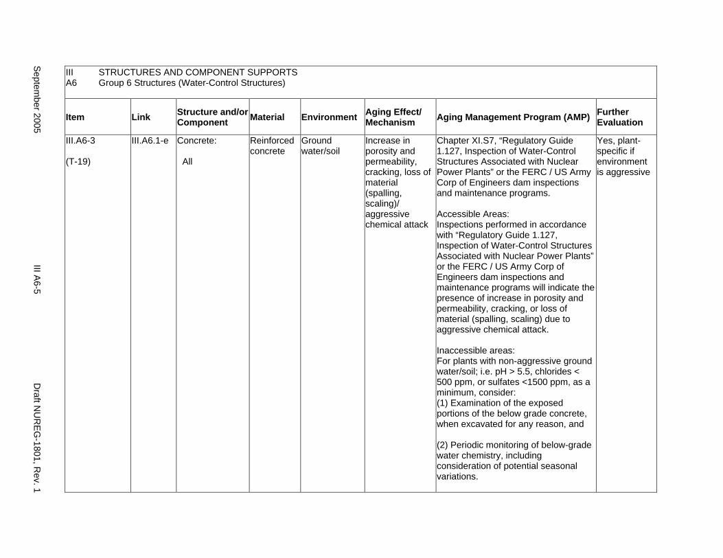
III STRUCTURES AND COMPONENT SUPPORTS A6 Group 6 Structures (Water-Control Structures)
Item Link Structure and/or Component Material Environment Aging Effect/
Mechanism Aging Management Program (AMP) Further Evaluation
III.A6-3
(T-19)
III.A6.1-e Concrete:
All
Reinforced concrete
Ground water/soil
Increase in porosity and permeability, cracking, loss of material (spalling, scaling)/ aggressive chemical attack
Chapter XI.S7, “Regulatory Guide 1.127, Inspection of Water-Control Structures Associated with Nuclear Power Plants” or the FERC / US Army Corp of Engineers dam inspections and maintenance programs.
Accessible Areas: Inspections performed in accordance with “Regulatory Guide 1.127, Inspection of Water-Control Structures Associated with Nuclear Power Plants” or the FERC / US Army Corp of Engineers dam inspections and maintenance programs will indicate the presence of increase in porosity and permeability, cracking, or loss of material (spalling, scaling) due to aggressive chemical attack.
Inaccessible areas: For plants with non-aggressive ground water/soil; i.e. pH > 5.5, chlorides < 500 ppm, or sulfates <1500 ppm, as a minimum, consider: (1) Examination of the exposed portions of the below grade concrete, when excavated for any reason, and
(2) Periodic monitoring of below-grade water chemistry, including consideration of potential seasonal variations.
Yes, plant-specific if environment is aggressive
Septem
ber 2005 III A
6-5 D
raft NU
REG
-1801, Rev. 1
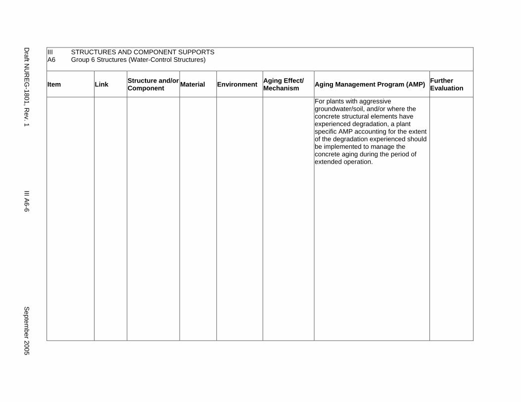
III A6
STRUCTURES AND COMPONENT SUPPORTS Group 6 Structures (Water-Control Structures)
Item Link Structure and/or Component Material Environment Aging Effect/
Mechanism Aging Management Program (AMP) Further Evaluation
For plants with aggressive groundwater/soil, and/or where the concrete structural elements have experienced degradation, a plant specific AMP accounting for the extent of the degradation experienced should be implemented to manage the concrete aging during the period of extended operation.
Draft N
UR
EG-1801, R
ev. 1 III A
6-6 S
eptember 2005

III STRUCTURES AND COMPONENT SUPPORTS A6 Group 6 Structures (Water-Control Structures)
Item Link Structure and/or Component Material Environment Aging Effect/
Mechanism Aging Management Program (AMP) Further Evaluation
III.A6-4
(T-08)
III.A6.1-f Concrete:
All
Reinforced concrete
Soil Cracks and distortion due to increased stress levels from settlement
Chapter XI.S6, “Structures Monitoring Program”
If a de-watering system is relied upon for control of settlement, then the licensee is to ensure proper functioning of the de-watering system through the period of extended operation.
Yes, if not within the scope of the applicant’s structures monitoring program or a de-watering system is relied upon
Septem
ber 2005 III A
6-7 D
raft NU
REG
-1801, Rev. 1
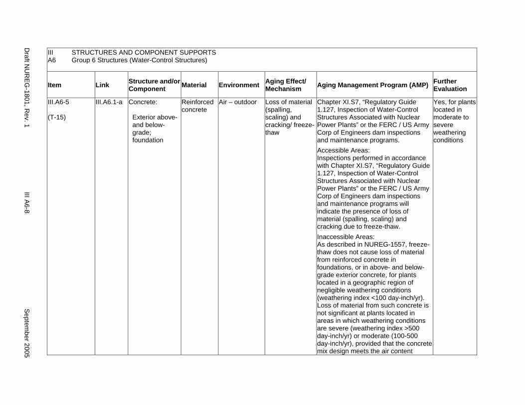
III STRUCTURES AND COMPONENT SUPPORTS A6 Group 6 Structures (Water-Control Structures)
Item Link Structure and/or Component Material Environment Aging Effect/
Mechanism Aging Management Program (AMP) Further Evaluation
III.A6-5
(T-15)
III.A6.1-a Concrete:
Exterior above- and below-grade; foundation
Reinforced concrete
Air – outdoor Loss of material (spalling, scaling) and cracking/ freeze-thaw
Chapter XI.S7, “Regulatory Guide 1.127, Inspection of Water-Control Structures Associated with Nuclear Power Plants” or the FERC / US Army Corp of Engineers dam inspections and maintenance programs. Accessible Areas: Inspections performed in accordance with Chapter XI.S7, “Regulatory Guide 1.127, Inspection of Water-Control Structures Associated with Nuclear Power Plants” or the FERC / US Army Corp of Engineers dam inspections and maintenance programs will indicate the presence of loss of material (spalling, scaling) and cracking due to freeze-thaw. Inaccessible Areas: As described in NUREG-1557, freeze-thaw does not cause loss of material from reinforced concrete in foundations, or in above- and below-grade exterior concrete, for plants located in a geographic region of negligible weathering conditions (weathering index <100 day-inch/yr). Loss of material from such concrete is not significant at plants located in areas in which weathering conditions are severe (weathering index >500 day-inch/yr) or moderate (100-500 day-inch/yr), provided that the concrete mix design meets the air content
Yes, for plants located in moderate to severe weathering conditions
Draft N
UR
EG-1801, R
ev. 1 III A
6-8 S
eptember 2005
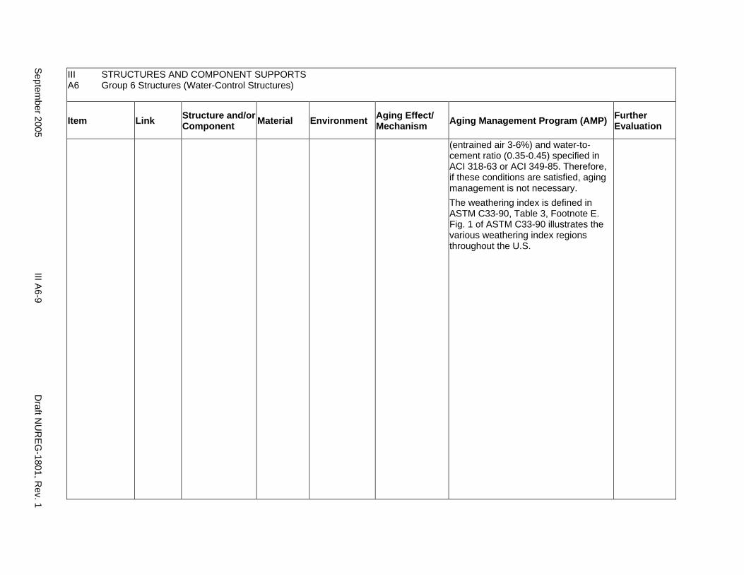
III A6
STRUCTURES AND COMPONENT SUPPORTS Group 6 Structures (Water-Control Structures)
Item Link Structure and/or Component Material Environment Aging Effect/
Mechanism Aging Management Program (AMP) Further Evaluation
(entrained air 3-6%) and water-tocement ratio (0.35-0.45) specified in ACI 318-63 or ACI 349-85. Therefore, if these conditions are satisfied, aging management is not necessary. The weathering index is defined in ASTM C33-90, Table 3, Footnote E. Fig. 1 of ASTM C33-90 illustrates the various weathering index regions throughout the U.S.
Septem
ber 2005 III A
6-9 D
raft NU
REG
-1801, Rev. 1
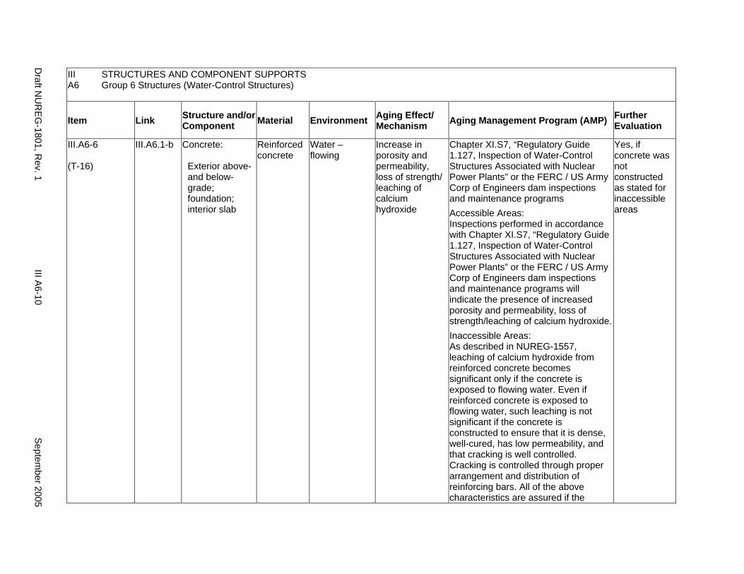
III STRUCTURES AND COMPONENT SUPPORTS A6 Group 6 Structures (Water-Control Structures)
Item Link Structure and/or Component Material Environment Aging Effect/
Mechanism Aging Management Program (AMP) Further Evaluation
III.A6-6
(T-16)
III.A6.1-b Concrete:
Exterior above- and below-grade; foundation; interior slab
Reinforced concrete
Water – flowing
Increase in porosity and permeability, loss of strength/ leaching of calcium hydroxide
Chapter XI.S7, “Regulatory Guide 1.127, Inspection of Water-Control Structures Associated with Nuclear Power Plants” or the FERC / US Army Corp of Engineers dam inspections and maintenance programs Accessible Areas: Inspections performed in accordance with Chapter XI.S7, “Regulatory Guide 1.127, Inspection of Water-Control Structures Associated with Nuclear Power Plants” or the FERC / US Army Corp of Engineers dam inspections and maintenance programs will indicate the presence of increased porosity and permeability, loss of strength/leaching of calcium hydroxide. Inaccessible Areas: As described in NUREG-1557, leaching of calcium hydroxide from reinforced concrete becomes significant only if the concrete is exposed to flowing water. Even if reinforced concrete is exposed to flowing water, such leaching is not significant if the concrete is constructed to ensure that it is dense, well-cured, has low permeability, and that cracking is well controlled. Cracking is controlled through proper arrangement and distribution of reinforcing bars. All of the above characteristics are assured if the
Yes, if concrete was not constructed as stated for inaccessible areas
Draft N
UR
EG-1801, R
ev. 1 III A
6-10 S
eptember 2005
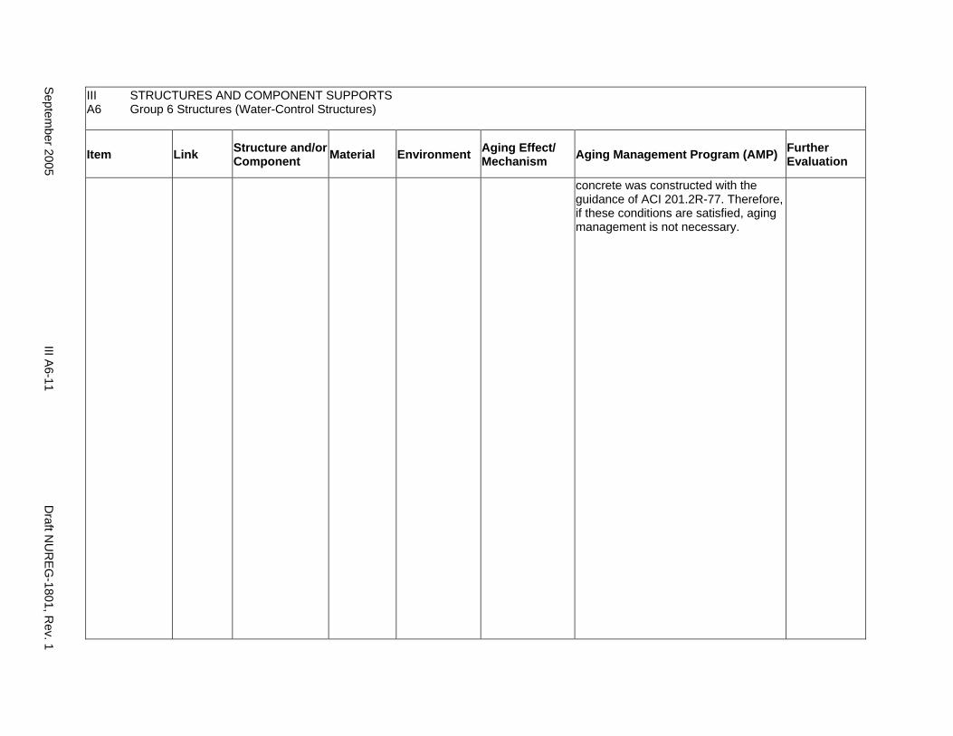
III A6
STRUCTURES AND COMPONENT SUPPORTS Group 6 Structures (Water-Control Structures)
Item Link Structure and/or Component Material Environment Aging Effect/
Mechanism Aging Management Program (AMP) Further Evaluation
concrete was constructed with the guidance of ACI 201.2R-77. Therefore, if these conditions are satisfied, aging management is not necessary.
Septem
ber 2005 III A
6-11 D
raft NU
REG
-1801, Rev. 1
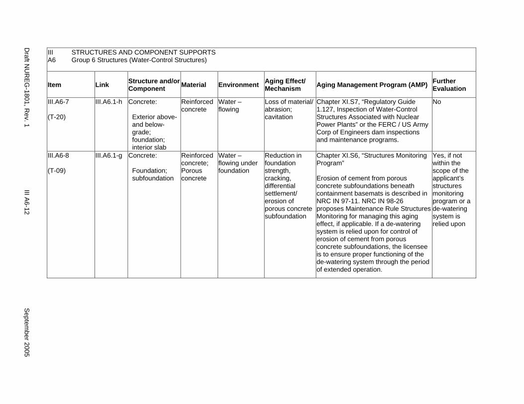
III STRUCTURES AND COMPONENT SUPPORTS A6 Group 6 Structures (Water-Control Structures)
Item Link Structure and/or Component Material Environment Aging Effect/
Mechanism Aging Management Program (AMP) Further Evaluation
III.A6-7
(T-20)
III.A6.1-h Concrete:
Exterior above- and below-grade; foundation; interior slab
Reinforced concrete
Water – flowing
Loss of material/ abrasion; cavitation
Chapter XI.S7, “Regulatory Guide 1.127, Inspection of Water-Control Structures Associated with Nuclear Power Plants” or the FERC / US Army Corp of Engineers dam inspections and maintenance programs.
No
III.A6-8
(T-09)
III.A6.1-g Concrete:
Foundation; subfoundation
Reinforced concrete; Porous concrete
Water – flowing under foundation
Reduction in foundation strength, cracking, differential settlement/ erosion of porous concrete subfoundation
Chapter XI.S6, “Structures Monitoring Program”
Erosion of cement from porous concrete subfoundations beneath containment basemats is described in NRC IN 97-11. NRC IN 98-26 proposes Maintenance Rule Structures Monitoring for managing this aging effect, if applicable. If a de-watering system is relied upon for control of erosion of cement from porous concrete subfoundations, the licensee is to ensure proper functioning of the de-watering system through the period of extended operation.
Yes, if not within the scope of the applicant’s structures monitoring program or a de-watering system is relied upon
Draft N
UR
EG-1801, R
ev. 1 III A
6-12 S
eptember 2005
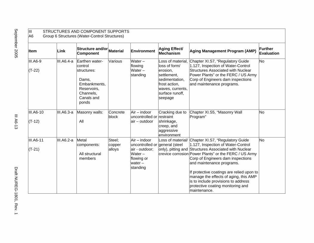
III STRUCTURES AND COMPONENT SUPPORTS A6 Group 6 Structures (Water-Control Structures)
Item Link Structure and/or Component Material Environment Aging Effect/
Mechanism Aging Management Program (AMP) Further Evaluation
III.A6-9
(T-22)
III.A6.4-a Earthen water-control structures:
Dams, Embankments, Reservoirs, Channels, Canals and ponds
Various Water – flowing Water – standing
Loss of material, loss of form/ erosion, settlement, sedimentation, frost action, waves, currents, surface runoff, seepage
Chapter XI.S7, “Regulatory Guide 1.127, Inspection of Water-Control Structures Associated with Nuclear Power Plants” or the FERC / US Army Corp of Engineers dam inspections and maintenance programs.
No
III.A6-10
(T-12)
III.A6.3-a Masonry walls:
All
Concrete block
Air – indoor uncontrolled or air – outdoor
Cracking due to restraint shrinkage, creep, and aggressive environment
Chapter XI.S5, “Masonry Wall Program”
No
III.A6-11
(T-21)
III.A6.2-a Metal components:
All structural members
Steel; copper alloys
Air – indoor uncontrolled or air - outdoor; Water – flowing or water – standing
Loss of material/ general (steel only), pitting and crevice corrosion
Chapter XI.S7, “Regulatory Guide 1.127, Inspection of Water-Control Structures Associated with Nuclear Power Plants” or the FERC / US Army Corp of Engineers dam inspections and maintenance programs.
If protective coatings are relied upon to manage the effects of aging, this AMP is to include provisions to address protective coating monitoring and maintenance.
No
Septem
ber 2005 III A
6-13 D
raft NU
REG
-1801, Rev. 1
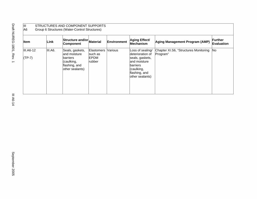
III STRUCTURES AND COMPONENT SUPPORTS A6 Group 6 Structures (Water-Control Structures)
Item Link Structure and/or Component Material Environment Aging Effect/
Mechanism Aging Management Program (AMP) Further Evaluation
III.A6-12
(TP-7)
III.A6. Seals, gaskets, and moisture barriers (caulking, flashing, and other sealants)
Elastomers such as EPDM rubber
Various Loss of sealing/ deterioration of seals, gaskets, and moisture barriers (caulking, flashing, and other sealants)
Chapter XI.S6, “Structures Monitoring Program”
No
Draft N
UR
EG-1801, R
ev. 1 III A
6-14 S
eptember 2005
A7. GROUP 7 STRUCTURES (CONCRETE TANKS AND MISSILE BARRIERS)
Systems, Structures, and Components
This section addresses the elements of concrete tanks and missile barriers. For this group, the applicable structural elements are identified: concrete and steel. The aging management review is presented for each applicable combination of structural element and aging effect.
System Interfaces
Physical interfaces exist with any system or component that either penetrates the structure wall or is supported by the structure wall, floor, and roof. The direct interface is through the system or component supports that are anchored to the structure. Structures also protect housed systems and components from internal and external design basis events. In the case of tanks, there is a functional interface with the associated system. Water-control structures are integral parts of the systems that provide plant cooling water and residual heat removal.
September 2005 III A7-1 Draft NUREG-1801, Rev. 1
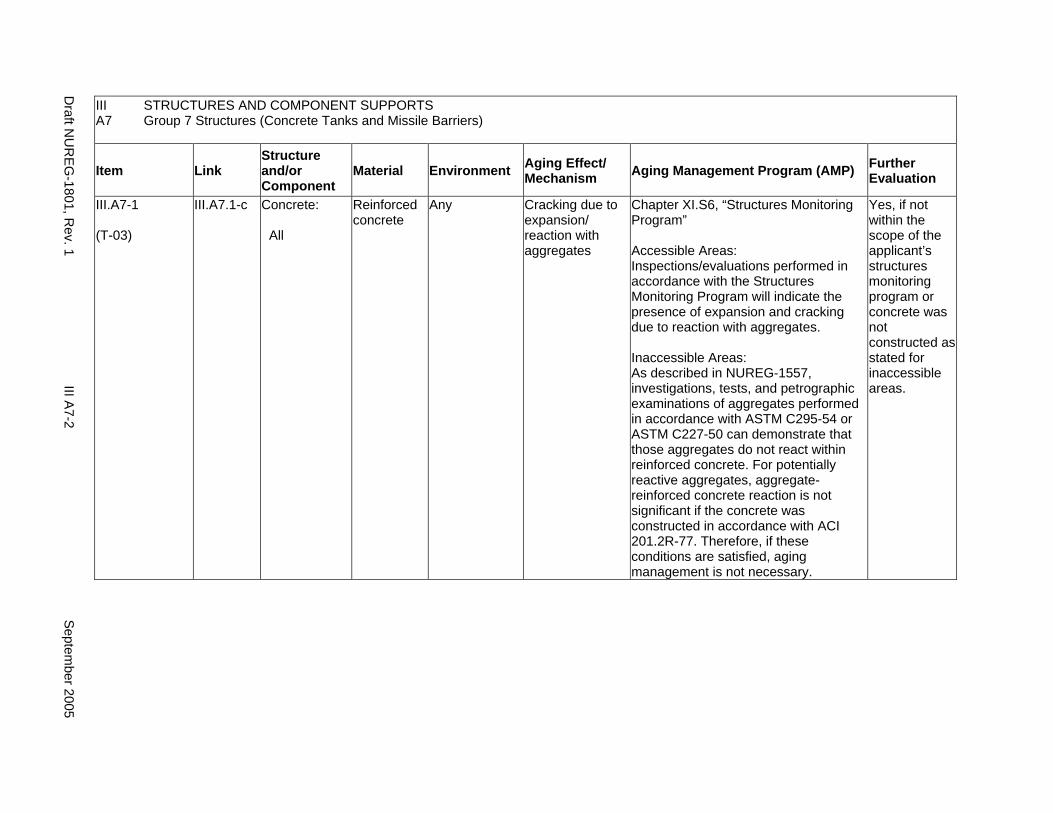
III STRUCTURES AND COMPONENT SUPPORTS A7 Group 7 Structures (Concrete Tanks and Missile Barriers)
Item Link Structure and/or Component
Material Environment Aging Effect/ Mechanism Aging Management Program (AMP) Further
Evaluation
III.A7-1
(T-03)
III.A7.1-c Concrete:
All
Reinforced concrete
Any Cracking due to expansion/ reaction with aggregates
Chapter XI.S6, “Structures Monitoring Program”
Accessible Areas: Inspections/evaluations performed in accordance with the Structures Monitoring Program will indicate the presence of expansion and cracking due to reaction with aggregates.
Inaccessible Areas: As described in NUREG-1557, investigations, tests, and petrographic examinations of aggregates performed in accordance with ASTM C295-54 or ASTM C227-50 can demonstrate that those aggregates do not react within reinforced concrete. For potentially reactive aggregates, aggregate-reinforced concrete reaction is not significant if the concrete was constructed in accordance with ACI 201.2R-77. Therefore, if these conditions are satisfied, aging management is not necessary.
Yes, if not within the scope of the applicant’s structures monitoring program or concrete was not constructed as stated for inaccessible areas.
Draft N
UR
EG-1801, R
ev. 1 III A
7-2 S
eptember 2005
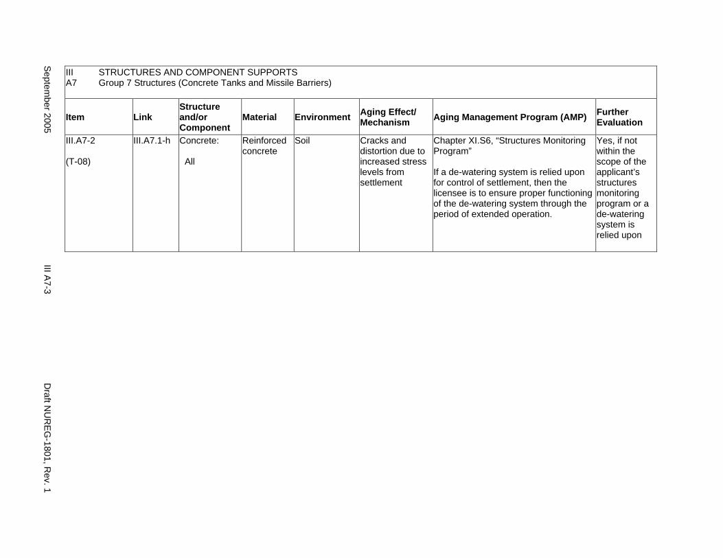
III STRUCTURES AND COMPONENT SUPPORTS A7 Group 7 Structures (Concrete Tanks and Missile Barriers)
Item Link Structure and/or Component
Material Environment Aging Effect/ Mechanism Aging Management Program (AMP) Further
Evaluation
III.A7-2
(T-08)
III.A7.1-h Concrete:
All
Reinforced concrete
Soil Cracks and distortion due to increased stress levels from settlement
Chapter XI.S6, “Structures Monitoring Program”
If a de-watering system is relied upon for control of settlement, then the licensee is to ensure proper functioning of the de-watering system through the period of extended operation.
Yes, if not within the scope of the applicant’s structures monitoring program or a de-watering system is relied upon
Septem
ber 2005 III A
7-3 D
raft NU
REG
-1801, Rev. 1
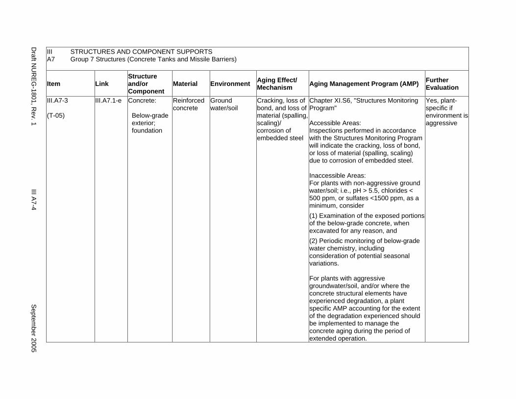
III STRUCTURES AND COMPONENT SUPPORTS A7 Group 7 Structures (Concrete Tanks and Missile Barriers)
Item Link Structure and/or Component
Material Environment Aging Effect/ Mechanism Aging Management Program (AMP) Further
Evaluation
III.A7-3
(T-05)
III.A7.1-e Concrete:
Below-grade exterior; foundation
Reinforced concrete
Ground water/soil
Cracking, loss of bond, and loss of material (spalling, scaling)/ corrosion of embedded steel
Chapter XI.S6, "Structures Monitoring Program"
Accessible Areas: Inspections performed in accordance with the Structures Monitoring Program will indicate the cracking, loss of bond, or loss of material (spalling, scaling) due to corrosion of embedded steel.
Inaccessible Areas: For plants with non-aggressive ground water/soil; i.e., pH > 5.5, chlorides < 500 ppm, or sulfates <1500 ppm, as a minimum, consider (1) Examination of the exposed portions of the below-grade concrete, when excavated for any reason, and (2) Periodic monitoring of below-grade water chemistry, including consideration of potential seasonal variations.
For plants with aggressive groundwater/soil, and/or where the concrete structural elements have experienced degradation, a plant specific AMP accounting for the extent of the degradation experienced should be implemented to manage the concrete aging during the period of extended operation.
Yes, plant-specific if environment is aggressive
Draft N
UR
EG-1801, R
ev. 1 III A
7-4 S
eptember 2005
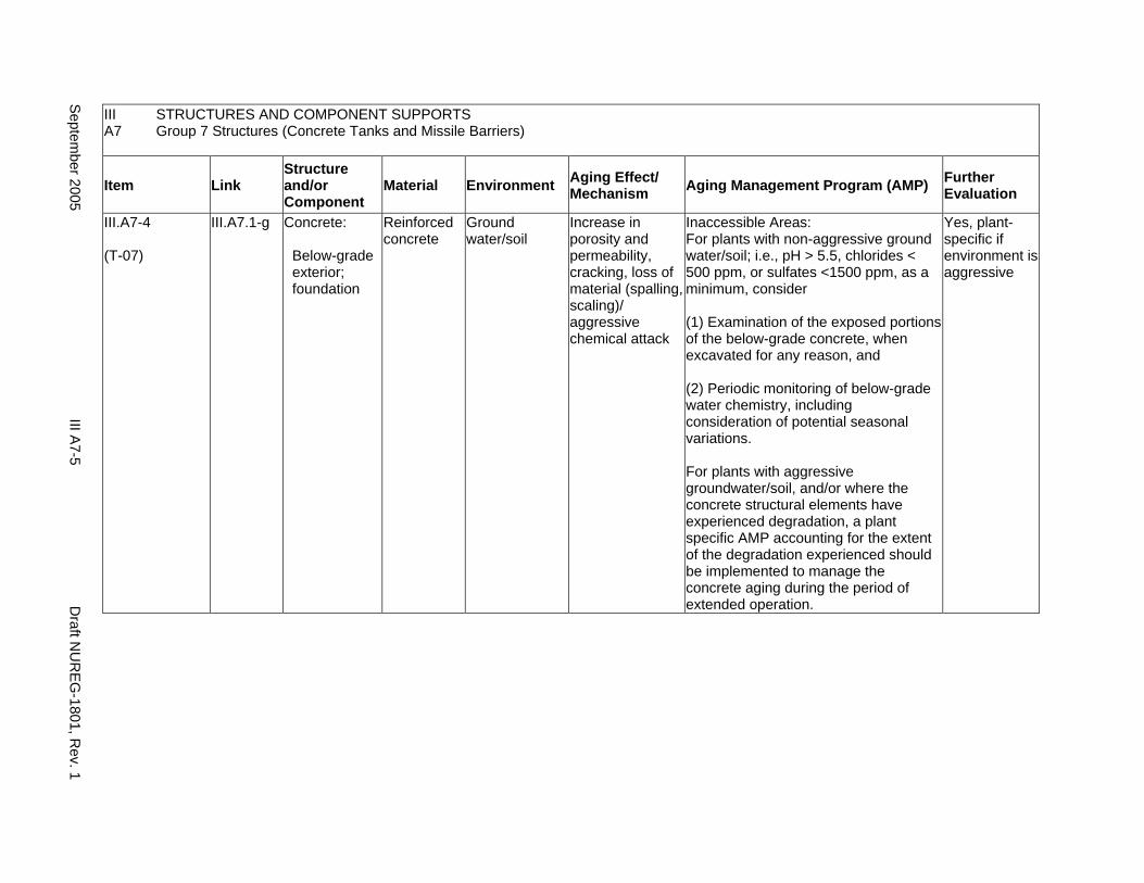
III STRUCTURES AND COMPONENT SUPPORTS A7 Group 7 Structures (Concrete Tanks and Missile Barriers)
Item Link Structure and/or Component
Material Environment Aging Effect/ Mechanism Aging Management Program (AMP) Further
Evaluation
III.A7-4
(T-07)
III.A7.1-g Concrete:
Below-grade exterior; foundation
Reinforced concrete
Ground water/soil
Increase in porosity and permeability, cracking, loss of material (spalling, scaling)/ aggressive chemical attack
Inaccessible Areas: For plants with non-aggressive ground water/soil; i.e., pH > 5.5, chlorides < 500 ppm, or sulfates <1500 ppm, as a minimum, consider
(1) Examination of the exposed portions of the below-grade concrete, when excavated for any reason, and
(2) Periodic monitoring of below-grade water chemistry, including consideration of potential seasonal variations.
For plants with aggressive groundwater/soil, and/or where the concrete structural elements have experienced degradation, a plant specific AMP accounting for the extent of the degradation experienced should be implemented to manage the concrete aging during the period of extended operation.
Yes, plant-specific if environment is aggressive
Septem
ber 2005 III A
7-5 D
raft NU
REG
-1801, Rev. 1
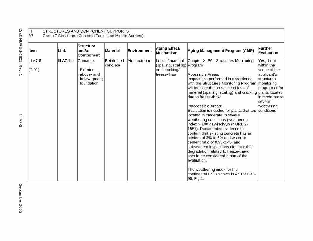
III STRUCTURES AND COMPONENT SUPPORTS A7 Group 7 Structures (Concrete Tanks and Missile Barriers)
Item Link Structure and/or Component
Material Environment Aging Effect/ Mechanism Aging Management Program (AMP) Further
Evaluation
III.A7-5
(T-01)
III.A7.1-a Concrete:
Exterior above- and below-grade; foundation
Reinforced concrete
Air – outdoor Loss of material (spalling, scaling) and cracking/ freeze-thaw
Chapter XI.S6, “Structures Monitoring Program”
Accessible Areas: Inspections performed in accordance with the Structures Monitoring Program will indicate the presence of loss of material (spalling, scaling) and cracking due to freeze-thaw.
Inaccessible Areas: Evaluation is needed for plants that are located in moderate to severe weathering conditions (weathering index > 100 day-inch/yr) (NUREG1557). Documented evidence to confirm that existing concrete has air content of 3% to 6% and water-tocement ratio of 0.35-0.45, and subsequent inspections did not exhibit degradation related to freeze-thaw, should be considered a part of the evaluation.
The weathering index for the continental US is shown in ASTM C3390, Fig.1.
Yes, if not within the scope of the applicant’s structures monitoring program or for plants located in moderate to severe weathering conditions
Draft N
UR
EG-1801, R
ev. 1 III A
7-6 S
eptember 2005

III A7
STRUCTURES AND COMPONENT SUPPORTS Group 7 Structures (Concrete Tanks and Missile Barriers)
Item Link Structure and/or Component
Material Environment Aging Effect/ Mechanism Aging Management Program (AMP) Further
Evaluation
III.A7-6
(T-02)
III.A7.1-b Concrete:
Exterior above- and below-grade; foundation
Reinforced concrete
Water – flowing Increase in porosity and permeability, loss of strength/ leaching of calcium hydroxide
Chapter XI.S6, "Structures Monitoring Program"
Accessible areas: Inspections performed in accordance with the Structures Monitoring Program will indicate the presence of increase in porosity, and permeability due to leaching of calcium hydroxide.
Inaccessible Areas: An aging management program is not necessary, even if reinforced concrete is exposed to flowing water, if there is documented evidence that confirms the in-place concrete was constructed in accordance with the recommendations in ACI 201.2R-77.
Yes, if concrete was not constructed as stated for inaccessible areas
Septem
ber 2005 III A
7-7 D
raft NU
REG
-1801, Rev. 1
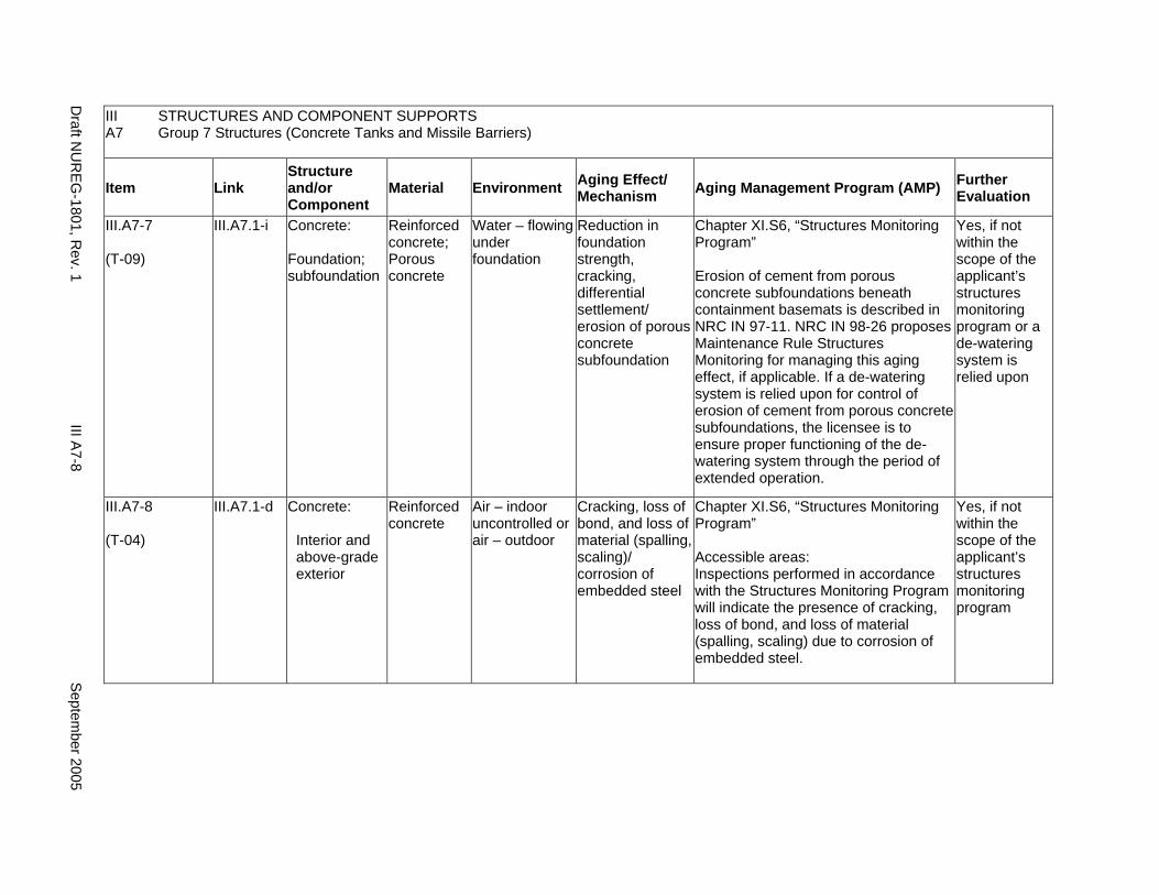
III A7
STRUCTURES AND COMPONENT SUPPORTS Group 7 Structures (Concrete Tanks and Missile Barriers)
Item Link Structure and/or Component
Material Environment Aging Effect/ Mechanism Aging Management Program (AMP) Further
Evaluation
III.A7-7
(T-09)
III.A7.1-i Concrete:
Foundation; subfoundation
Reinforced concrete; Porous concrete
Water – flowing under foundation
Reduction in foundation strength, cracking, differential settlement/ erosion of porous concrete subfoundation
Chapter XI.S6, “Structures Monitoring Program”
Erosion of cement from porous concrete subfoundations beneath containment basemats is described in NRC IN 97-11. NRC IN 98-26 proposes Maintenance Rule Structures Monitoring for managing this aging effect, if applicable. If a de-watering system is relied upon for control of erosion of cement from porous concrete subfoundations, the licensee is to ensure proper functioning of the dewatering system through the period of extended operation.
Yes, if not within the scope of the applicant’s structures monitoring program or a de-watering system is relied upon
III.A7-8
(T-04)
III.A7.1-d Concrete:
Interior and above-grade exterior
Reinforced concrete
Air – indoor uncontrolled or air – outdoor
Cracking, loss of bond, and loss of material (spalling, scaling)/ corrosion of embedded steel
Chapter XI.S6, “Structures Monitoring Program”
Accessible areas: Inspections performed in accordance with the Structures Monitoring Program will indicate the presence of cracking, loss of bond, and loss of material (spalling, scaling) due to corrosion of embedded steel.
Yes, if not within the scope of the applicant’s structures monitoring program
Draft N
UR
EG-1801, R
ev. 1 III A
7-8 S
eptember 2005
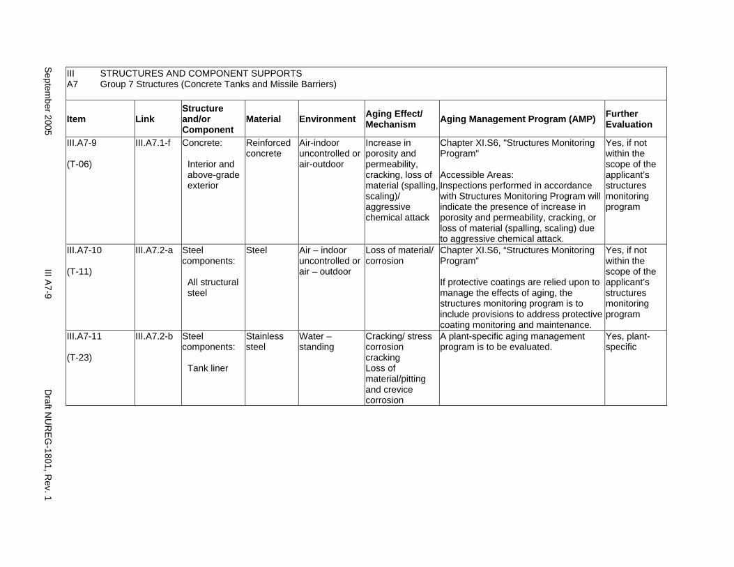
III STRUCTURES AND COMPONENT SUPPORTS A7 Group 7 Structures (Concrete Tanks and Missile Barriers)
Item Link Structure and/or Component
Material Environment Aging Effect/ Mechanism Aging Management Program (AMP) Further
Evaluation
III.A7-9
(T-06)
III.A7.1-f Concrete:
Interior and above-grade exterior
Reinforced concrete
Air-indoor uncontrolled or air-outdoor
Increase in porosity and permeability, cracking, loss of material (spalling, scaling)/ aggressive chemical attack
Chapter XI.S6, "Structures Monitoring Program"
Accessible Areas: Inspections performed in accordance with Structures Monitoring Program will indicate the presence of increase in porosity and permeability, cracking, or loss of material (spalling, scaling) due to aggressive chemical attack.
Yes, if not within the scope of the applicant’s structures monitoring program
III.A7-10
(T-11)
III.A7.2-a Steel components:
All structural steel
Steel Air – indoor uncontrolled or air – outdoor
Loss of material/ corrosion
Chapter XI.S6, “Structures Monitoring Program”
If protective coatings are relied upon to manage the effects of aging, the structures monitoring program is to include provisions to address protective coating monitoring and maintenance.
Yes, if not within the scope of the applicant’s structures monitoring program
III.A7-11
(T-23)
III.A7.2-b Steel components:
Tank liner
Stainless steel
Water – standing
Cracking/ stress corrosion cracking Loss of material/pitting and crevice corrosion
A plant-specific aging management program is to be evaluated.
Yes, plant-specific
Septem
ber 2005 III A
7-9 D
raft NU
REG
-1801, Rev. 1

DraftD
raftDraft N
UR
EG
1801, Rev. 1
III A8-10
Septem
ber 2005-
5
This Page Intentionally Left Blank
Draft NUREG-1801, Rev. 1 III A7-10 September 2005
A8. GROUP 8 STRUCTURES (STEEL TANKS AND MISSILE BARRIERS)
Systems, Structures, and Components
This section addresses the elements of steel tanks and missile barriers. For this group, the applicable structural elements are identified: concrete and steel. The aging management review is presented for each applicable combination of structural element and aging effect.
System Interfaces
Physical interfaces exist with any system or component that either penetrates the structure wall or is supported by the structure wall, floor, and roof. The direct interface is through the system or component supports that are anchored to the structure. Structures also protect housed systems and components from internal and external design basis events. In the case of tanks, there is a functional interface with the associated system. Water-control structures are integral parts of the systems that provide plant cooling water and residual heat removal.
September 2005 III A8-1 Draft NUREG-1801, Rev. 1
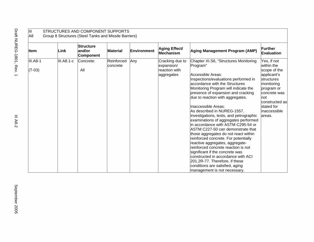
III STRUCTURES AND COMPONENT SUPPORTS A8 Group 8 Structures (Steel Tanks and Missile Barriers)
Item Link Structure and/or Component
Material Environment Aging Effect/ Mechanism Aging Management Program (AMP) Further
Evaluation
III.A8-1
(T-03)
III.A8.1-c Concrete:
All
Reinforced concrete
Any Cracking due to expansion/ reaction with aggregates
Chapter XI.S6, “Structures Monitoring Program”
Accessible Areas: Inspections/evaluations performed in accordance with the Structures Monitoring Program will indicate the presence of expansion and cracking due to reaction with aggregates.
Inaccessible Areas: As described in NUREG-1557, investigations, tests, and petrographic examinations of aggregates performed in accordance with ASTM C295-54 or ASTM C227-50 can demonstrate that those aggregates do not react within reinforced concrete. For potentially reactive aggregates, aggregate-reinforced concrete reaction is not significant if the concrete was constructed in accordance with ACI 201.2R-77. Therefore, if these conditions are satisfied, aging management is not necessary.
Yes, if not within the scope of the applicant’s structures monitoring program or concrete was not constructed as stated for inaccessible areas.
Draft N
UR
EG-1801, R
ev. 1 III A
8-2 S
eptember 2005

III STRUCTURES AND COMPONENT SUPPORTS A8 Group 8 Structures (Steel Tanks and Missile Barriers)
Item Link Structure and/or Component
Material Environment Aging Effect/ Mechanism Aging Management Program (AMP) Further
Evaluation
III.A8-2
(T-08)
III.A8.1-f Concrete:
All
Reinforced concrete
Soil Cracks and distortion due to increased stress levels from settlement
Chapter XI.S6, “Structures Monitoring Program”
If a de-watering system is relied upon for control of settlement, then the licensee is to ensure proper functioning of the de-watering system through the period of extended operation.
Yes, if not within the scope of the applicant’s structures monitoring program or a de-watering system is relied upon
Septem
ber 2005 III A
8-3 D
raft NU
REG
-1801, Rev. 1
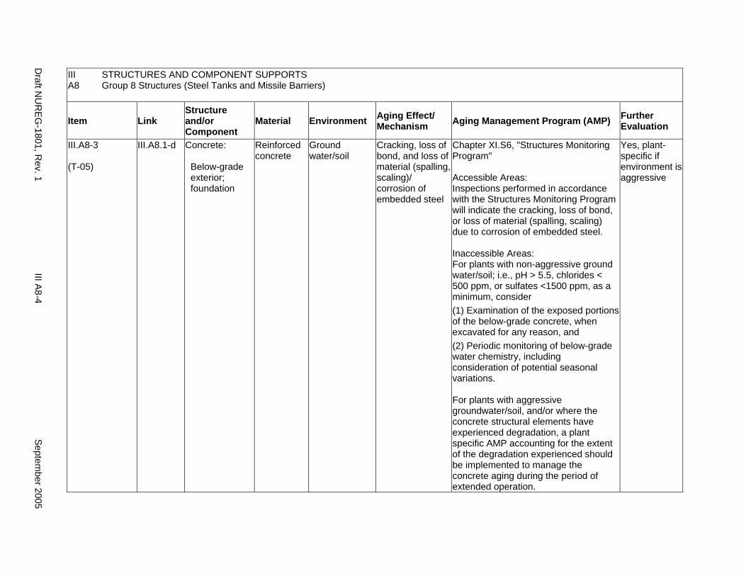
III STRUCTURES AND COMPONENT SUPPORTS A8 Group 8 Structures (Steel Tanks and Missile Barriers)
Item Link Structure and/or Component
Material Environment Aging Effect/ Mechanism Aging Management Program (AMP) Further
Evaluation
III.A8-3
(T-05)
III.A8.1-d Concrete:
Below-grade exterior; foundation
Reinforced concrete
Ground water/soil
Cracking, loss of bond, and loss of material (spalling, scaling)/ corrosion of embedded steel
Chapter XI.S6, "Structures Monitoring Program"
Accessible Areas: Inspections performed in accordance with the Structures Monitoring Program will indicate the cracking, loss of bond, or loss of material (spalling, scaling) due to corrosion of embedded steel.
Inaccessible Areas: For plants with non-aggressive ground water/soil; i.e., pH > 5.5, chlorides < 500 ppm, or sulfates <1500 ppm, as a minimum, consider (1) Examination of the exposed portions of the below-grade concrete, when excavated for any reason, and (2) Periodic monitoring of below-grade water chemistry, including consideration of potential seasonal variations.
For plants with aggressive groundwater/soil, and/or where the concrete structural elements have experienced degradation, a plant specific AMP accounting for the extent of the degradation experienced should be implemented to manage the concrete aging during the period of extended operation.
Yes, plant-specific if environment is aggressive
Draft N
UR
EG-1801, R
ev. 1 III A
8-4 S
eptember 2005
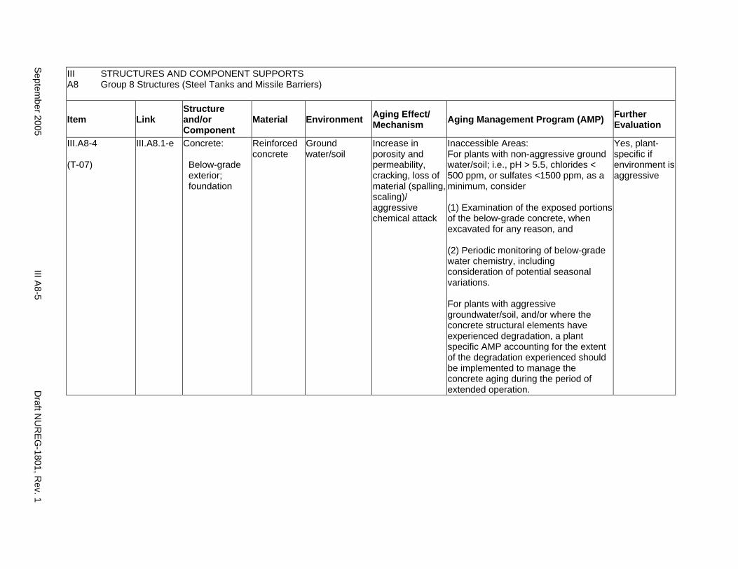
III STRUCTURES AND COMPONENT SUPPORTS A8 Group 8 Structures (Steel Tanks and Missile Barriers)
Item Link Structure and/or Component
Material Environment Aging Effect/ Mechanism Aging Management Program (AMP) Further
Evaluation
III.A8-4
(T-07)
III.A8.1-e Concrete:
Below-grade exterior; foundation
Reinforced concrete
Ground water/soil
Increase in porosity and permeability, cracking, loss of material (spalling, scaling)/ aggressive chemical attack
Inaccessible Areas: For plants with non-aggressive ground water/soil; i.e., pH > 5.5, chlorides < 500 ppm, or sulfates <1500 ppm, as a minimum, consider
(1) Examination of the exposed portions of the below-grade concrete, when excavated for any reason, and
(2) Periodic monitoring of below-grade water chemistry, including consideration of potential seasonal variations.
For plants with aggressive groundwater/soil, and/or where the concrete structural elements have experienced degradation, a plant specific AMP accounting for the extent of the degradation experienced should be implemented to manage the concrete aging during the period of extended operation.
Yes, plant-specific if environment is aggressive
Septem
ber 2005 III A
8-5 D
raft NU
REG
-1801, Rev. 1
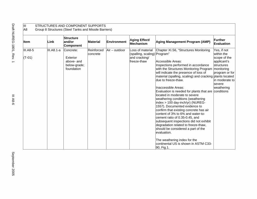
III STRUCTURES AND COMPONENT SUPPORTS A8 Group 8 Structures (Steel Tanks and Missile Barriers)
Item Link Structure and/or Component
Material Environment Aging Effect/ Mechanism Aging Management Program (AMP) Further
Evaluation
III.A8-5
(T-01)
III.A8.1-a Concrete:
Exterior above- and below-grade; foundation
Reinforced concrete
Air – outdoor Loss of material (spalling, scaling) and cracking/ freeze-thaw
Chapter XI.S6, “Structures Monitoring Program”
Accessible Areas: Inspections performed in accordance with the Structures Monitoring Program will indicate the presence of loss of material (spalling, scaling) and cracking due to freeze-thaw.
Inaccessible Areas: Evaluation is needed for plants that are located in moderate to severe weathering conditions (weathering index > 100 day-inch/yr) (NUREG1557). Documented evidence to confirm that existing concrete has air content of 3% to 6% and water-tocement ratio of 0.35-0.45, and subsequent inspections did not exhibit degradation related to freeze-thaw, should be considered a part of the evaluation.
The weathering index for the continental US is shown in ASTM C3390, Fig.1.
Yes, if not within the scope of the applicant’s structures monitoring program or for plants located in moderate to severe weathering conditions
Draft N
UR
EG-1801, R
ev. 1 III A
8-6 S
eptember 2005
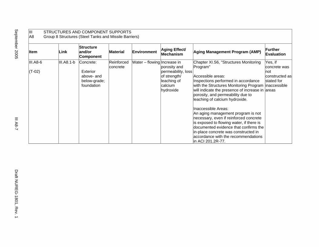
III A8
STRUCTURES AND COMPONENT SUPPORTS Group 8 Structures (Steel Tanks and Missile Barriers)
Item Link Structure and/or Component
Material Environment Aging Effect/ Mechanism Aging Management Program (AMP) Further
Evaluation
III.A8-6
(T-02)
III.A8.1-b Concrete:
Exterior above- and below-grade; foundation
Reinforced concrete
Water – flowing Increase in porosity and permeability, loss of strength/ leaching of calcium hydroxide
Chapter XI.S6, "Structures Monitoring Program"
Accessible areas: Inspections performed in accordance with the Structures Monitoring Program will indicate the presence of increase in porosity, and permeability due to leaching of calcium hydroxide.
Inaccessible Areas: An aging management program is not necessary, even if reinforced concrete is exposed to flowing water, if there is documented evidence that confirms the in-place concrete was constructed in accordance with the recommendations in ACI 201.2R-77.
Yes, if concrete was not constructed as stated for inaccessible areas
Septem
ber 2005 III A
8-7 D
raft NU
REG
-1801, Rev. 1
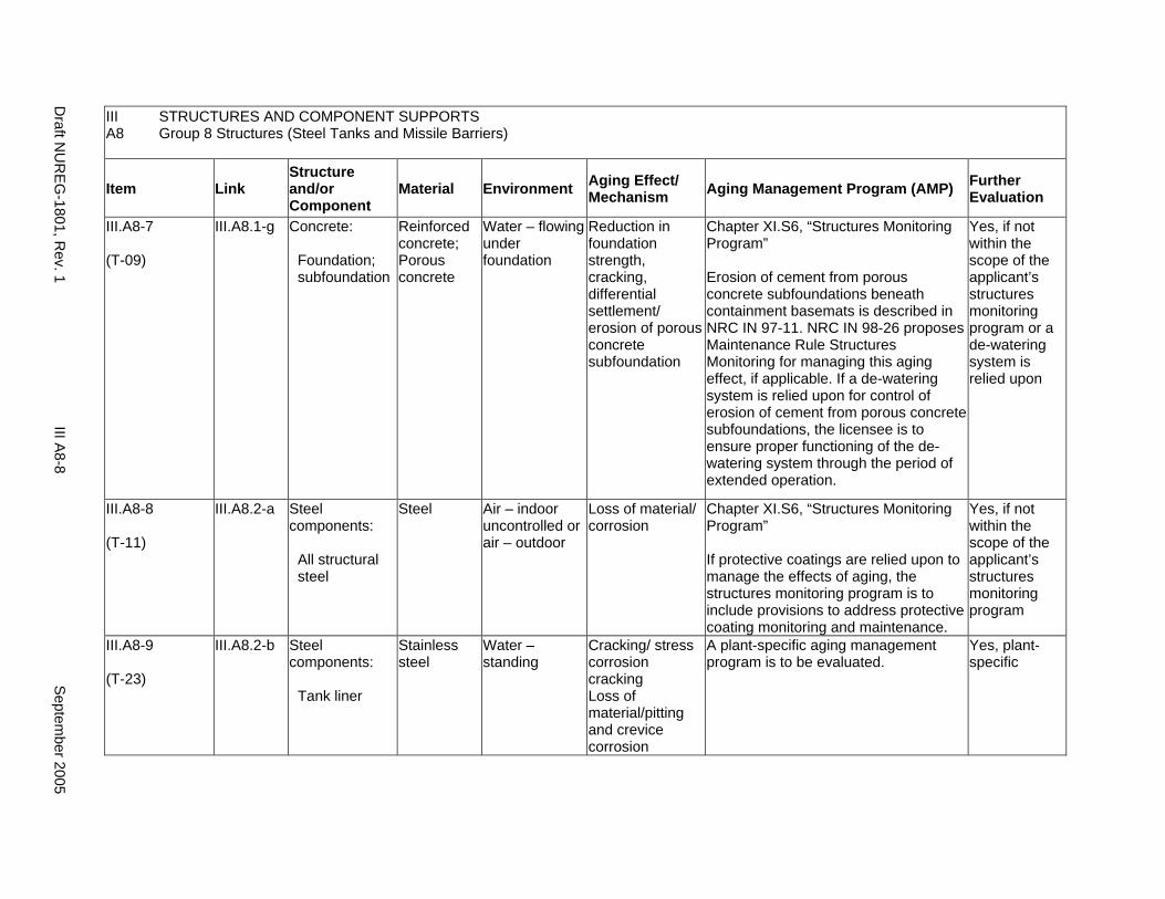
III A8
STRUCTURES AND COMPONENT SUPPORTS Group 8 Structures (Steel Tanks and Missile Barriers)
Item Link Structure and/or Component
Material Environment Aging Effect/ Mechanism Aging Management Program (AMP) Further
Evaluation
III.A8-7
(T-09)
III.A8.1-g Concrete:
Foundation; subfoundation
Reinforced concrete; Porous concrete
Water – flowing under foundation
Reduction in foundation strength, cracking, differential settlement/ erosion of porous concrete subfoundation
Chapter XI.S6, “Structures Monitoring Program”
Erosion of cement from porous concrete subfoundations beneath containment basemats is described in NRC IN 97-11. NRC IN 98-26 proposes Maintenance Rule Structures Monitoring for managing this aging effect, if applicable. If a de-watering system is relied upon for control of erosion of cement from porous concrete subfoundations, the licensee is to ensure proper functioning of the dewatering system through the period of extended operation.
Yes, if not within the scope of the applicant’s structures monitoring program or a de-watering system is relied upon
III.A8-8
(T-11)
III.A8.2-a Steel components:
All structural steel
Steel Air – indoor uncontrolled or air – outdoor
Loss of material/ corrosion
Chapter XI.S6, “Structures Monitoring Program”
If protective coatings are relied upon to manage the effects of aging, the structures monitoring program is to include provisions to address protective coating monitoring and maintenance.
Yes, if not within the scope of the applicant’s structures monitoring program
III.A8-9
(T-23)
III.A8.2-b Steel components:
Tank liner
Stainless steel
Water – standing
Cracking/ stress corrosion cracking Loss of material/pitting and crevice corrosion
A plant-specific aging management program is to be evaluated.
Yes, plant-specific
Draft N
UR
EG-1801, R
ev. 1 III A
8-8 S
eptember 2005
A9. GROUP 9 STRUCTURES (BWR UNIT VENT STACK)
Systems, Structures, and Components
This section addresses the elements of the boiling water reactor (BWR) unit vent stack. For this group, the applicable structural element is identified: concrete. The aging management review is presented for each applicable combination of structural element and aging effect.
System Interfaces
Physical interfaces exist with any system or component that either penetrates the structure wall or is supported by the structure wall, floor, and roof. The direct interface is through the system or component supports that are anchored to the structure. Structures also protect housed systems and components from internal and external design basis events. In the case of tanks, there is a functional interface with the associated system. Water-control structures are integral parts of the systems that provide plant cooling water and residual heat removal.
September 2005 III A9-1 Draft NUREG-1801, Rev. 1
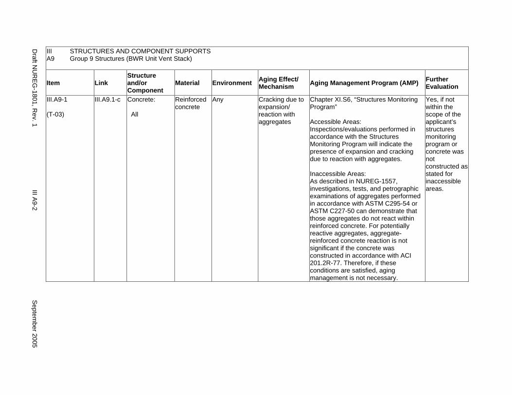
III STRUCTURES AND COMPONENT SUPPORTS A9 Group 9 Structures (BWR Unit Vent Stack)
Item Link Structure and/or Component
Material Environment Aging Effect/ Mechanism Aging Management Program (AMP) Further
Evaluation
III.A9-1
(T-03)
III.A9.1-c Concrete:
All
Reinforced concrete
Any Cracking due to expansion/ reaction with aggregates
Chapter XI.S6, “Structures Monitoring Program”
Accessible Areas: Inspections/evaluations performed in accordance with the Structures Monitoring Program will indicate the presence of expansion and cracking due to reaction with aggregates.
Inaccessible Areas: As described in NUREG-1557, investigations, tests, and petrographic examinations of aggregates performed in accordance with ASTM C295-54 or ASTM C227-50 can demonstrate that those aggregates do not react within reinforced concrete. For potentially reactive aggregates, aggregate-reinforced concrete reaction is not significant if the concrete was constructed in accordance with ACI 201.2R-77. Therefore, if these conditions are satisfied, aging management is not necessary.
Yes, if not within the scope of the applicant’s structures monitoring program or concrete was not constructed as stated for inaccessible areas.
Draft N
UR
EG-1801, R
ev. 1 III A
9-2 S
eptember 20055
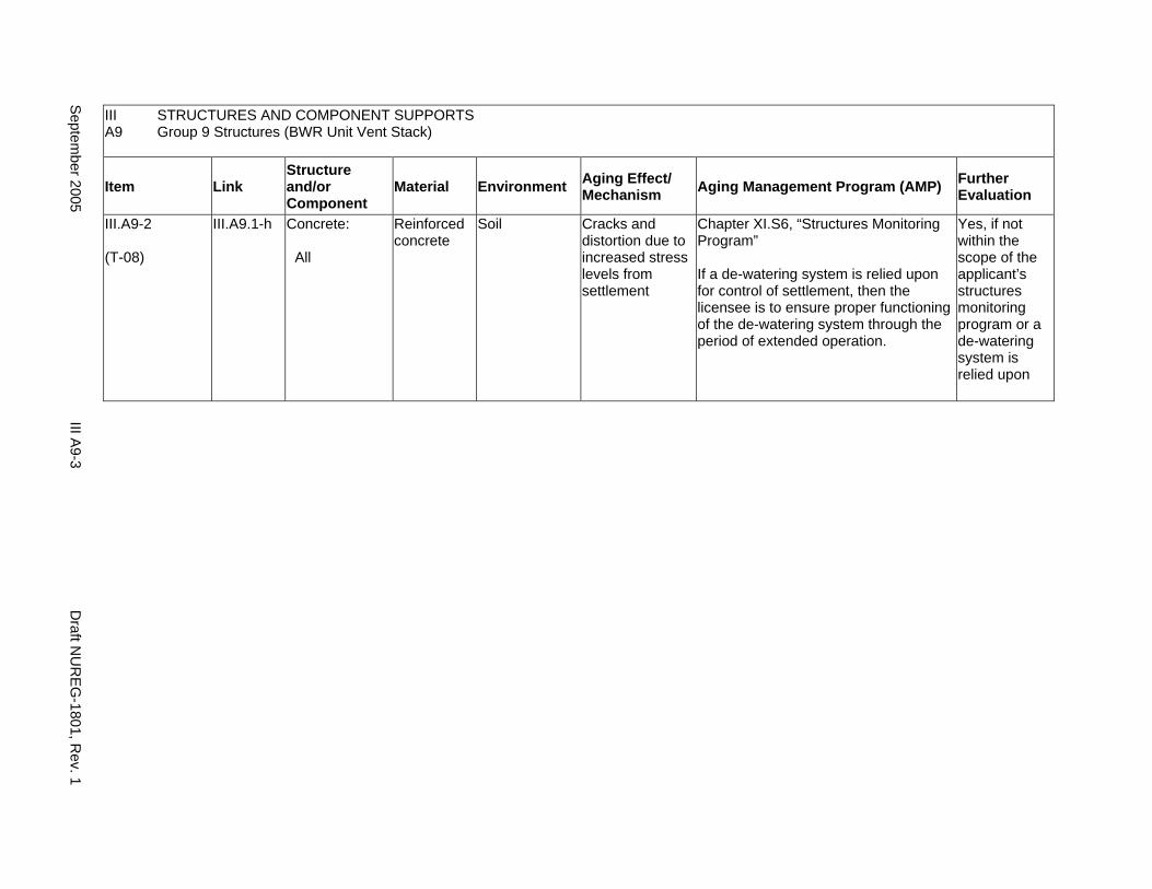
III STRUCTURES AND COMPONENT SUPPORTS A9 Group 9 Structures (BWR Unit Vent Stack)
Item Link Structure and/or Component
Material Environment Aging Effect/ Mechanism Aging Management Program (AMP) Further
Evaluation
III.A9-2
(T-08)
III.A9.1-h Concrete:
All
Reinforced concrete
Soil Cracks and distortion due to increased stress levels from settlement
Chapter XI.S6, “Structures Monitoring Program”
If a de-watering system is relied upon for control of settlement, then the licensee is to ensure proper functioning of the de-watering system through the period of extended operation.
Yes, if not within the scope of the applicant’s structures monitoring program or a de-watering system is relied upon
Septem
ber 2005 III A
9-3 D
raft NU
REG
-1801, Rev. 1
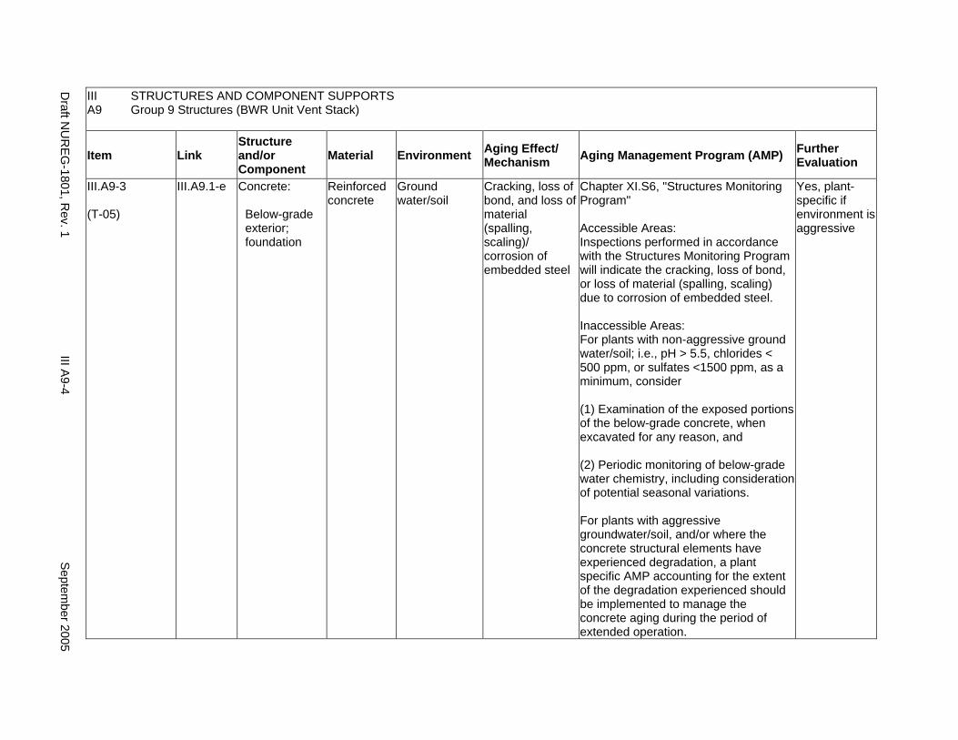
III STRUCTURES AND COMPONENT SUPPORTS A9 Group 9 Structures (BWR Unit Vent Stack)
Item Link Structure and/or Component
Material Environment Aging Effect/ Mechanism Aging Management Program (AMP) Further
Evaluation
III.A9-3
(T-05)
III.A9.1-e Concrete:
Below-grade exterior; foundation
Reinforced concrete
Ground water/soil
Cracking, loss of bond, and loss of material (spalling, scaling)/ corrosion of embedded steel
Chapter XI.S6, "Structures Monitoring Program"
Accessible Areas: Inspections performed in accordance with the Structures Monitoring Program will indicate the cracking, loss of bond, or loss of material (spalling, scaling) due to corrosion of embedded steel.
Inaccessible Areas: For plants with non-aggressive ground water/soil; i.e., pH > 5.5, chlorides < 500 ppm, or sulfates <1500 ppm, as a minimum, consider
(1) Examination of the exposed portions of the below-grade concrete, when excavated for any reason, and
(2) Periodic monitoring of below-grade water chemistry, including consideration of potential seasonal variations.
For plants with aggressive groundwater/soil, and/or where the concrete structural elements have experienced degradation, a plant specific AMP accounting for the extent of the degradation experienced should be implemented to manage the concrete aging during the period of extended operation.
Yes, plant-specific if environment is aggressive
Draft N
UR
EG-1801, R
ev. 1 III A
9-4 S
eptember 20055

III STRUCTURES AND COMPONENT SUPPORTS A9 Group 9 Structures (BWR Unit Vent Stack)
Item Link Structure and/or Component
Material Environment Aging Effect/ Mechanism Aging Management Program (AMP) Further
Evaluation
III.A9-4
(T-07)
III.A9.1-g Concrete:
Below-grade exterior; foundation
Reinforced concrete
Ground water/soil
Increase in porosity and permeability, cracking, loss of material (spalling, scaling)/ aggressive chemical attack
Inaccessible Areas: For plants with non-aggressive ground water/soil; i.e., pH > 5.5, chlorides < 500 ppm, or sulfates <1500 ppm, as a minimum, consider
(1) Examination of the exposed portions of the below-grade concrete, when excavated for any reason, and
(2) Periodic monitoring of below-grade water chemistry, including consideration of potential seasonal variations.
For plants with aggressive groundwater/soil, and/or where the concrete structural elements have experienced degradation, a plant specific AMP accounting for the extent of the degradation experienced should be implemented to manage the concrete aging during the period of extended operation.
Yes, plant-specific if environment is aggressive
Septem
ber 2005 III A
9-5 D
raft NU
REG
-1801, Rev. 1
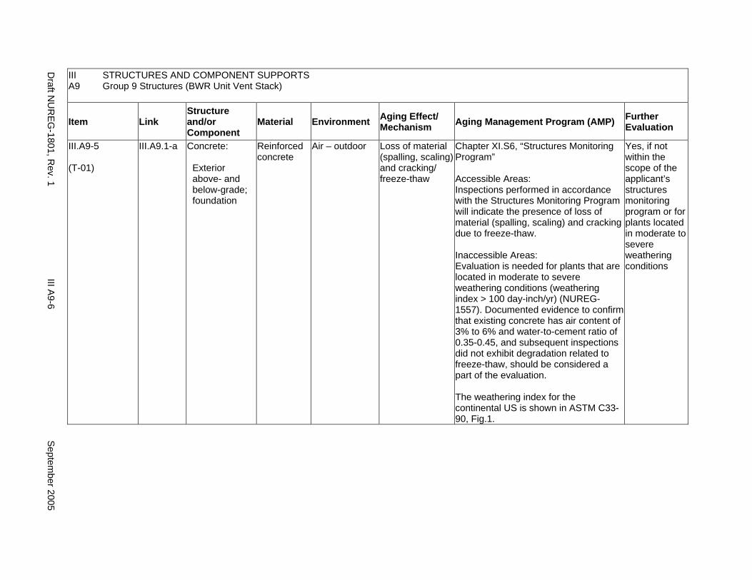
III STRUCTURES AND COMPONENT SUPPORTS A9 Group 9 Structures (BWR Unit Vent Stack)
Item Link Structure and/or Component
Material Environment Aging Effect/ Mechanism Aging Management Program (AMP) Further
Evaluation
III.A9-5
(T-01)
III.A9.1-a Concrete:
Exterior above- and below-grade; foundation
Reinforced concrete
Air – outdoor Loss of material (spalling, scaling) and cracking/ freeze-thaw
Chapter XI.S6, “Structures Monitoring Program”
Accessible Areas: Inspections performed in accordance with the Structures Monitoring Program will indicate the presence of loss of material (spalling, scaling) and cracking due to freeze-thaw.
Inaccessible Areas: Evaluation is needed for plants that are located in moderate to severe weathering conditions (weathering index > 100 day-inch/yr) (NUREG1557). Documented evidence to confirm that existing concrete has air content of 3% to 6% and water-to-cement ratio of 0.35-0.45, and subsequent inspections did not exhibit degradation related to freeze-thaw, should be considered a part of the evaluation.
The weathering index for the continental US is shown in ASTM C3390, Fig.1.
Yes, if not within the scope of the applicant’s structures monitoring program or for plants located in moderate to severe weathering conditions
Draft N
UR
EG-1801, R
ev. 1 III A
9-6 S
eptember 20055
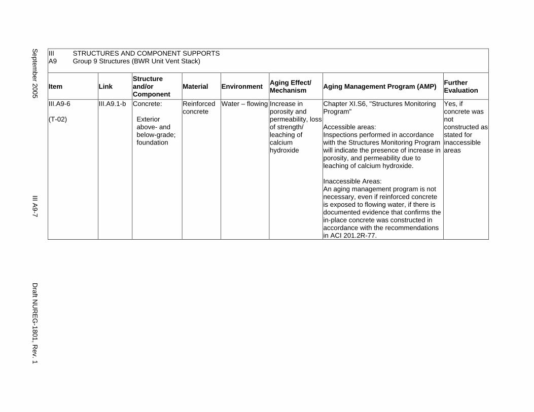
III STRUCTURES AND COMPONENT SUPPORTS A9 Group 9 Structures (BWR Unit Vent Stack)
Item Link Structure and/or Component
Material Environment Aging Effect/ Mechanism Aging Management Program (AMP) Further
Evaluation
III.A9-6
(T-02)
III.A9.1-b Concrete:
Exterior above- and below-grade; foundation
Reinforced concrete
Water – flowing Increase in porosity and permeability, loss of strength/ leaching of calcium hydroxide
Chapter XI.S6, "Structures Monitoring Program"
Accessible areas: Inspections performed in accordance with the Structures Monitoring Program will indicate the presence of increase in porosity, and permeability due to leaching of calcium hydroxide.
Inaccessible Areas: An aging management program is not necessary, even if reinforced concrete is exposed to flowing water, if there is documented evidence that confirms the in-place concrete was constructed in accordance with the recommendations in ACI 201.2R-77.
Yes, if concrete was not constructed as stated for inaccessible areas
Septem
ber 2005 III A
9-7 D
raft NU
REG
-1801, Rev. 1

III STRUCTURES AND COMPONENT SUPPORTS A9 Group 9 Structures (BWR Unit Vent Stack)
Item Link Structure and/or Component
Material Environment Aging Effect/ Mechanism Aging Management Program (AMP) Further
Evaluation
III.A9-7
(T-09)
III.A9.1-i Concrete:
Foundation; subfoundation
Reinforced concrete; Porous concrete
Water – flowing under foundation
Reduction in foundation strength, cracking, differential settlement/ erosion of porous concrete subfoundation
Chapter XI.S6, “Structures Monitoring Program”
Erosion of cement from porous concrete subfoundations beneath containment basemats is described in NRC IN 97-11. NRC IN 98-26 proposes Maintenance Rule Structures Monitoring for managing this aging effect, if applicable. If a de-watering system is relied upon for control of erosion of cement from porous concrete subfoundations, the licensee is to ensure proper functioning of the dewatering system through the period of extended operation.
Yes, if not within the scope of the applicant’s structures monitoring program or a de-watering system is relied upon
III.A9-8
(T-04)
III.A9.1-d Concrete:
Interior and above-grade exterior
Reinforced concrete
Air – indoor uncontrolled or air – outdoor
Cracking, loss of bond, and loss of material (spalling, scaling)/ corrosion of embedded steel
Chapter XI.S6, “Structures Monitoring Program”
Accessible areas: Inspections performed in accordance with the Structures Monitoring Program will indicate the presence of cracking, loss of bond, and loss of material (spalling, scaling) due to corrosion of embedded steel.
Yes, if not within the scope of the applicant’s structures monitoring program
Draft N
UR
EG-1801, R
ev. 1 III A
9-8 S
eptember 20055
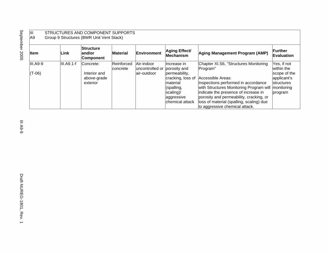
III STRUCTURES AND COMPONENT SUPPORTS A9 Group 9 Structures (BWR Unit Vent Stack)
Item Link Structure and/or Component
Material Environment Aging Effect/ Mechanism Aging Management Program (AMP) Further
Evaluation
III.A9-9
(T-06)
III.A9.1-f Concrete:
Interior and above-grade exterior
Reinforced concrete
Air-indoor uncontrolled or air-outdoor
Increase in porosity and permeability, cracking, loss of material (spalling, scaling)/ aggressive chemical attack
Chapter XI.S6, "Structures Monitoring Program"
Accessible Areas: Inspections performed in accordance with Structures Monitoring Program will indicate the presence of increase in porosity and permeability, cracking, or loss of material (spalling, scaling) due to aggressive chemical attack.
Yes, if not within the scope of the applicant’s structures monitoring program
Septem
ber 2005 III A
9-9 D
raft NU
REG
-1801, Rev. 1

This Page Intentionally Left Blank
Draft NUREG-1801, Rev. 1 III A9-10 September 2005
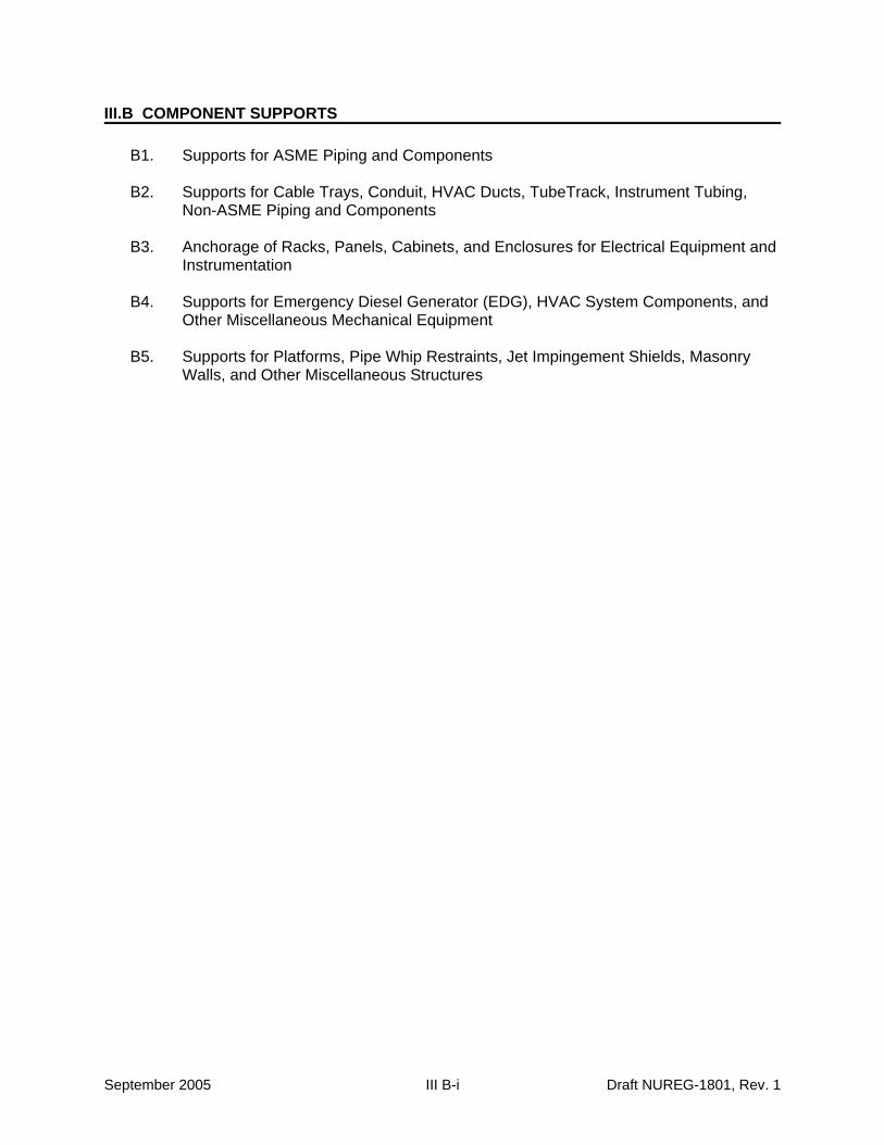
III.B COMPONENT SUPPORTS
B1. Supports for ASME Piping and Components
B2. Supports for Cable Trays, Conduit, HVAC Ducts, TubeTrack, Instrument Tubing, Non-ASME Piping and Components
B3. Anchorage of Racks, Panels, Cabinets, and Enclosures for Electrical Equipment and Instrumentation
B4. Supports for Emergency Diesel Generator (EDG), HVAC System Components, and Other Miscellaneous Mechanical Equipment
B5. Supports for Platforms, Pipe Whip Restraints, Jet Impingement Shields, Masonry Walls, and Other Miscellaneous Structures
September 2005 III B-i Draft NUREG-1801, Rev. 1
This Page Intentionally Left Blank
Draft NUREG-1801, Rev. 1 III B-ii September 2005
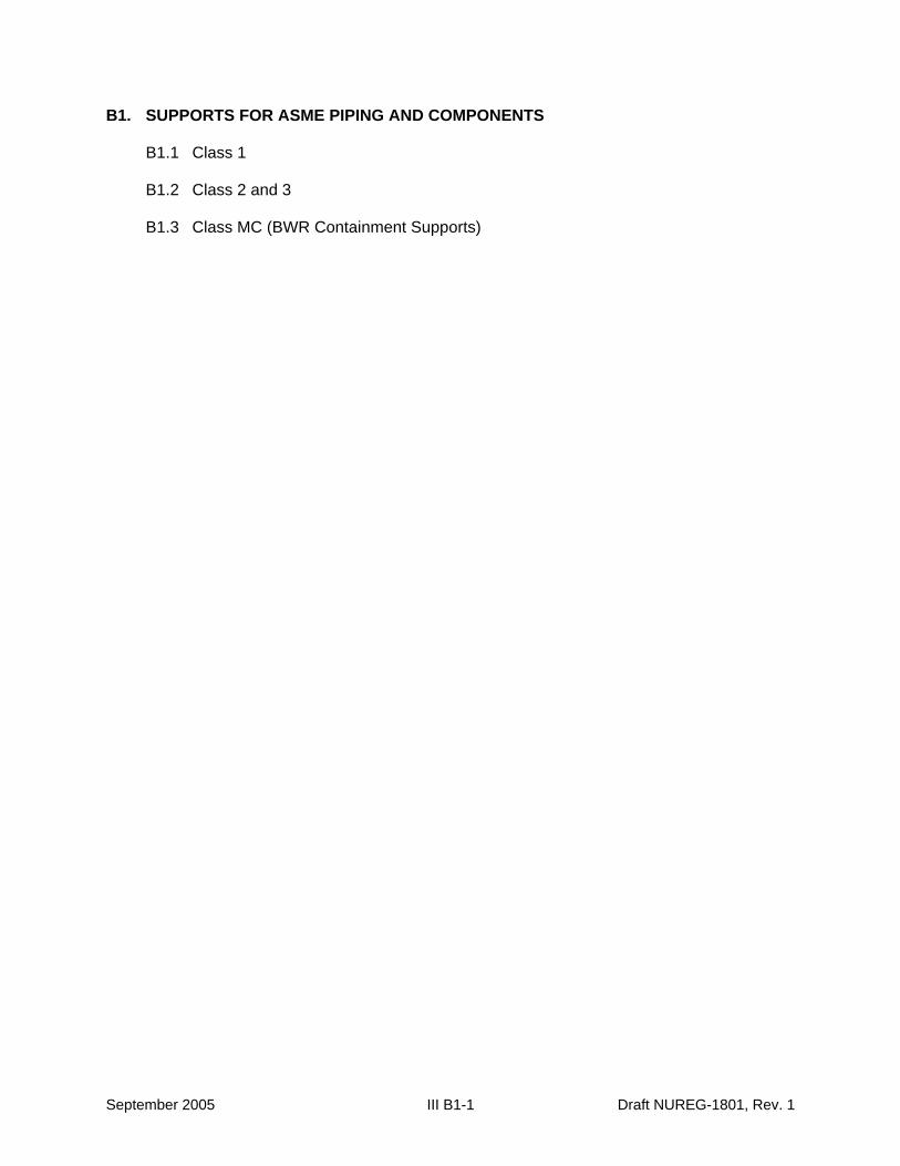
B1. SUPPORTS FOR ASME PIPING AND COMPONENTS
B1.1 Class 1
B1.2 Class 2 and 3
B1.3 Class MC (BWR Containment Supports)
September 2005 III B1-1 Draft NUREG-1801, Rev. 1

This Page Intentionally Left Blank
Draft NUREG-1801, Rev. 1 III B1-2 September 2005
B1. SUPPORTS FOR ASME PIPING AND COMPONENTS
Systems, Structures, and Components
This section addresses supports and anchorage for ASME piping systems and components. It is subdivided into Class 1 (III.B1.1), Class 2 and 3 (III.B1.2), and Class MC (III.B1.3). Applicable aging effects are identified and the aging management review is presented for each applicable combination of support component and aging effect.
System Interfaces
Physical interfaces exist with the structure, system, or component being supported and with the building structural element to which the support is anchored. A primary function of supports is to provide anchorage of the supported element for internal and external design basis events, so that the supported element can perform its intended function.
September 2005 III B1-3 Draft NUREG-1801, Rev. 1
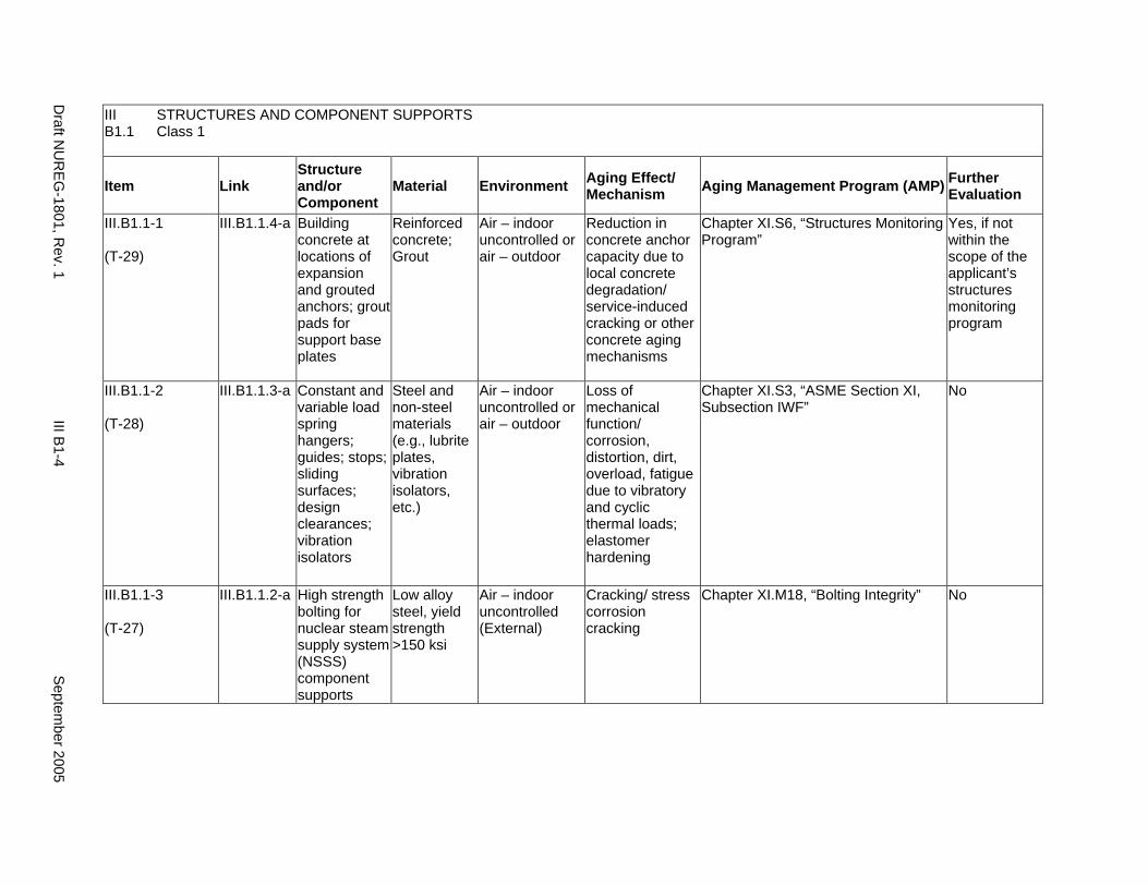
III STRUCTURES AND COMPONENT SUPPORTS B1.1 Class 1
Item Link Structure and/or Component
Material Environment Aging Effect/ Mechanism Aging Management Program (AMP) Further
Evaluation
III.B1.1-1
(T-29)
III.B1.1.4-a Building concrete at locations of expansion and grouted anchors; grout pads for support base plates
Reinforced concrete; Grout
Air – indoor uncontrolled or air – outdoor
Reduction in concrete anchor capacity due to local concrete degradation/ service-induced cracking or other concrete aging mechanisms
Chapter XI.S6, “Structures Monitoring Program”
Yes, if not within the scope of the applicant’s structures monitoring program
III.B1.1-2
(T-28)
III.B1.1.3-a Constant and variable load spring hangers; guides; stops; sliding surfaces; design clearances; vibration isolators
Steel and non-steel materials (e.g., lubrite plates, vibration isolators, etc.)
Air – indoor uncontrolled or air – outdoor
Loss of mechanical function/ corrosion, distortion, dirt, overload, fatigue due to vibratory and cyclic thermal loads; elastomer hardening
Chapter XI.S3, “ASME Section XI, Subsection IWF”
No
III.B1.1-3
(T-27)
III.B1.1.2-a High strength bolting for nuclear steam supply system (NSSS) component supports
Low alloy steel, yield strength >150 ksi
Air – indoor uncontrolled (External)
Cracking/ stress corrosion cracking
Chapter XI.M18, “Bolting Integrity” No
Draft N
UR
EG-1801, R
ev. 1 III B
1-4 S
eptember 2005
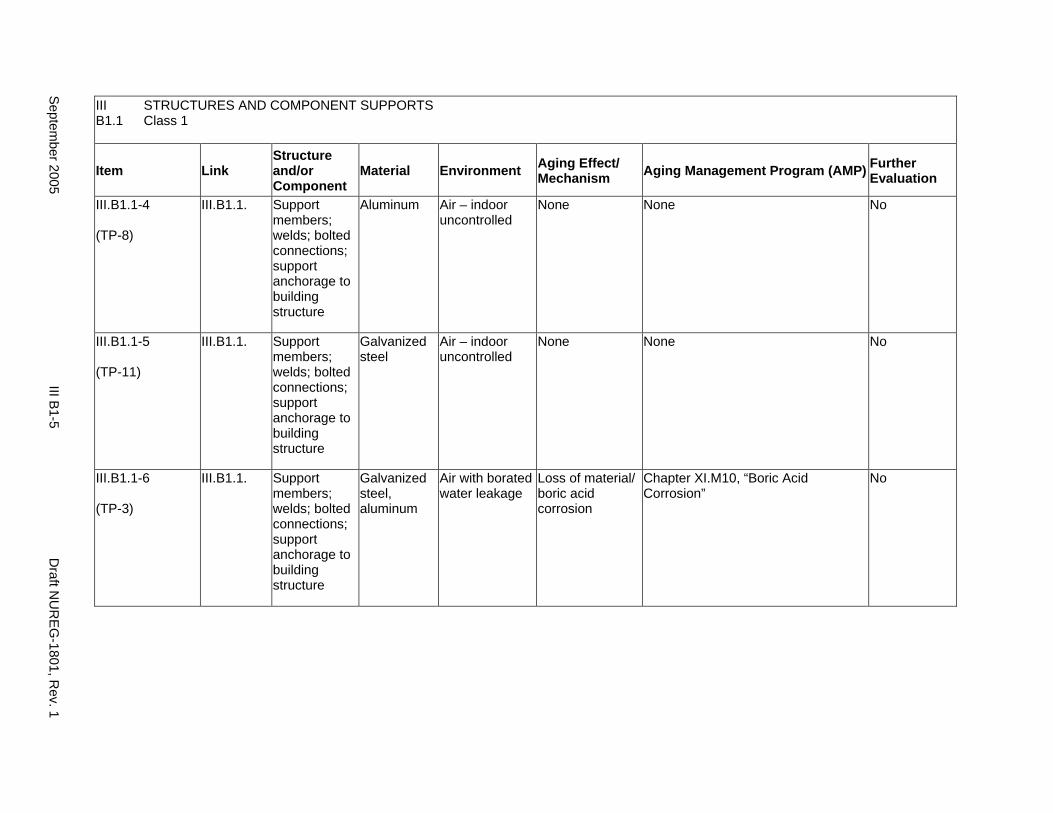
III STRUCTURES AND COMPONENT SUPPORTS B1.1 Class 1
Item Link Structure and/or Component
Material Environment Aging Effect/ Mechanism Aging Management Program (AMP) Further
Evaluation
III.B1.1-4
(TP-8)
III.B1.1. Support members; welds; bolted connections; support anchorage to building structure
Aluminum Air – indoor uncontrolled
None None No
III.B1.1-5
(TP-11)
III.B1.1. Support members; welds; bolted connections; support anchorage to building structure
Galvanized steel
Air – indoor uncontrolled
None None No
III.B1.1-6
(TP-3)
III.B1.1. Support members; welds; bolted connections; support anchorage to building structure
Galvanized steel, aluminum
Air with borated water leakage
Loss of material/ boric acid corrosion
Chapter XI.M10, “Boric Acid Corrosion”
No
Septem
ber 2005 III B
1-5 D
raft NU
REG
-1801, Rev. 1
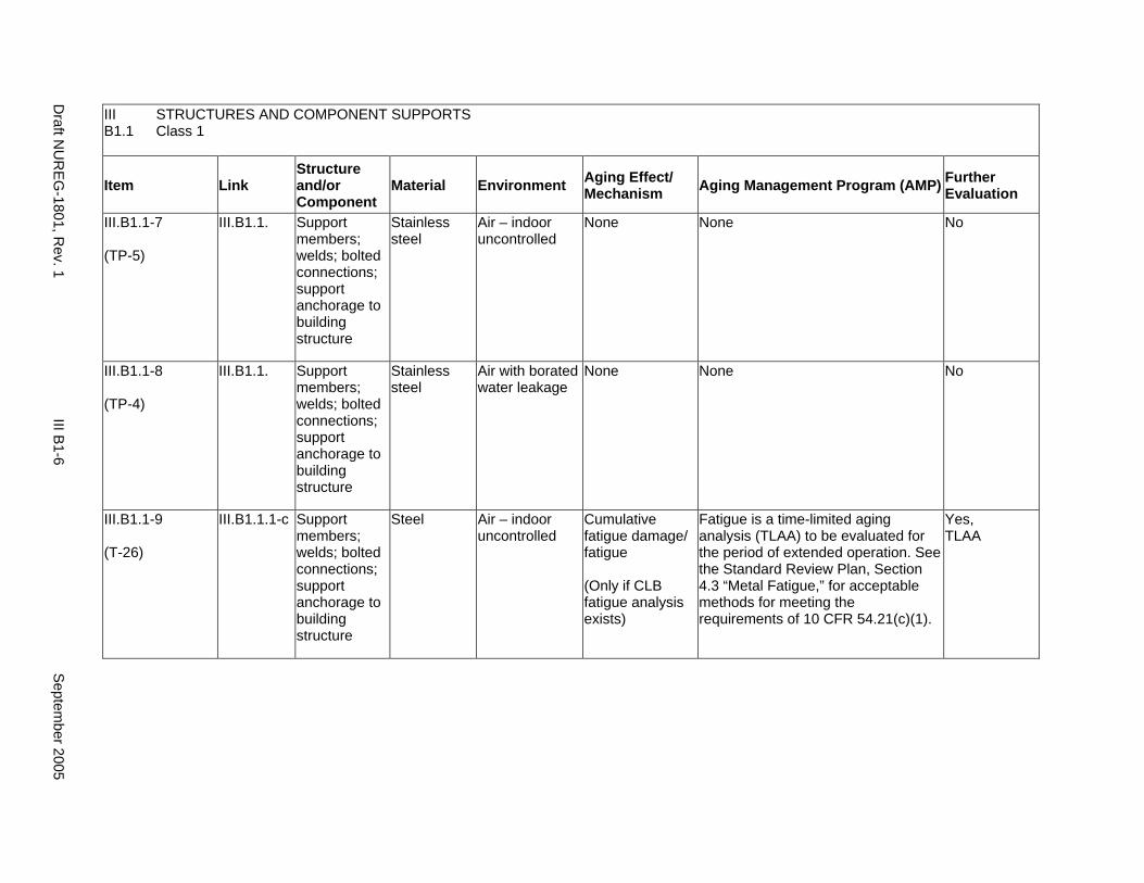
III STRUCTURES AND COMPONENT SUPPORTS B1.1 Class 1
Item Link Structure and/or Component
Material Environment Aging Effect/ Mechanism Aging Management Program (AMP) Further
Evaluation
III.B1.1-7
(TP-5)
III.B1.1. Support members; welds; bolted connections; support anchorage to building structure
Stainless steel
Air – indoor uncontrolled
None None No
III.B1.1-8
(TP-4)
III.B1.1. Support members; welds; bolted connections; support anchorage to building structure
Stainless steel
Air with borated water leakage
None None No
III.B1.1-9
(T-26)
III.B1.1.1-c Support members; welds; bolted connections; support anchorage to building structure
Steel Air – indoor uncontrolled
Cumulative fatigue damage/ fatigue
(Only if CLB fatigue analysis exists)
Fatigue is a time-limited aging analysis (TLAA) to be evaluated for the period of extended operation. See the Standard Review Plan, Section 4.3 “Metal Fatigue,” for acceptable methods for meeting the requirements of 10 CFR 54.21(c)(1).
Yes, TLAA
Draft N
UR
EG-1801, R
ev. 1 III B
1-6 S
eptember 2005
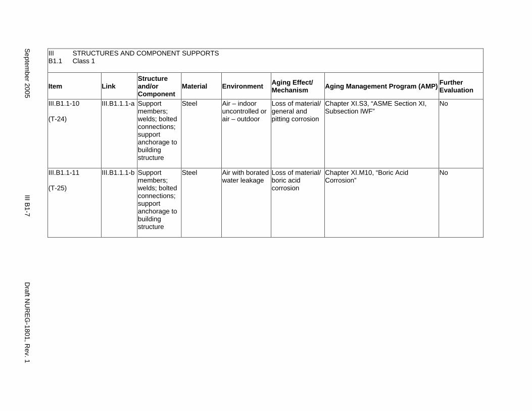
III STRUCTURES AND COMPONENT SUPPORTS B1.1 Class 1
Item Link Structure and/or Component
Material Environment Aging Effect/ Mechanism Aging Management Program (AMP) Further
Evaluation
III.B1.1-10
(T-24)
III.B1.1.1-a Support members; welds; bolted connections; support anchorage to building structure
Steel Air – indoor uncontrolled or air – outdoor
Loss of material/ general and pitting corrosion
Chapter XI.S3, “ASME Section XI, Subsection IWF”
No
III.B1.1-11
(T-25)
III.B1.1.1-b Support members; welds; bolted connections; support anchorage to building structure
Steel Air with borated water leakage
Loss of material/ boric acid corrosion
Chapter XI.M10, “Boric Acid Corrosion”
No
Septem
ber 2005 III B
1-7 D
raft NU
REG
-1801, Rev. 1
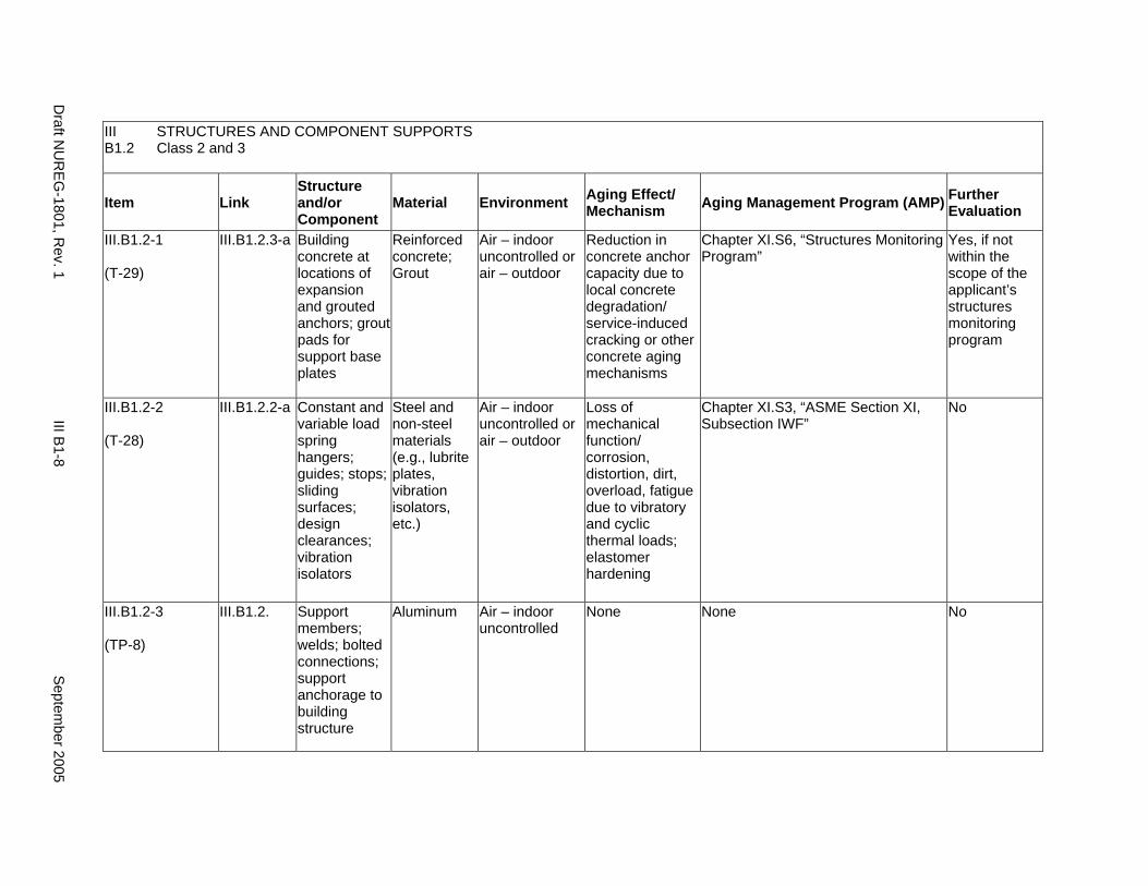
III STRUCTURES AND COMPONENT SUPPORTS B1.2 Class 2 and 3
Item Link Structure and/or Component
Material Environment Aging Effect/ Mechanism Aging Management Program (AMP) Further
Evaluation
III.B1.2-1
(T-29)
III.B1.2.3-a Building concrete at locations of expansion and grouted anchors; grout pads for support base plates
Reinforced concrete; Grout
Air – indoor uncontrolled or air – outdoor
Reduction in concrete anchor capacity due to local concrete degradation/ service-induced cracking or other concrete aging mechanisms
Chapter XI.S6, “Structures Monitoring Program”
Yes, if not within the scope of the applicant’s structures monitoring program
III.B1.2-2
(T-28)
III.B1.2.2-a Constant and variable load spring hangers; guides; stops; sliding surfaces; design clearances; vibration isolators
Steel and non-steel materials (e.g., lubrite plates, vibration isolators, etc.)
Air – indoor uncontrolled or air – outdoor
Loss of mechanical function/ corrosion, distortion, dirt, overload, fatigue due to vibratory and cyclic thermal loads; elastomer hardening
Chapter XI.S3, “ASME Section XI, Subsection IWF”
No
III.B1.2-3
(TP-8)
III.B1.2. Support members; welds; bolted connections; support anchorage to building structure
Aluminum Air – indoor uncontrolled
None None No
Draft N
UR
EG-1801, R
ev. 1 III B
1-8 S
eptember 2005
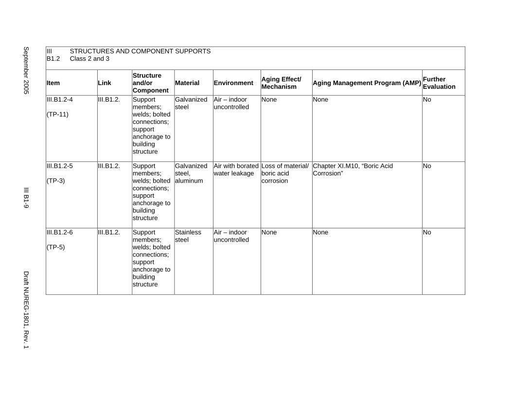
III STRUCTURES AND COMPONENT SUPPORTS B1.2 Class 2 and 3
Item Link Structure and/or Component
Material Environment Aging Effect/ Mechanism Aging Management Program (AMP) Further
Evaluation
III.B1.2-4
(TP-11)
III.B1.2. Support members; welds; bolted connections; support anchorage to building structure
Galvanized steel
Air – indoor uncontrolled
None None No
III.B1.2-5
(TP-3)
III.B1.2. Support members; welds; bolted connections; support anchorage to building structure
Galvanized steel, aluminum
Air with borated water leakage
Loss of material/ boric acid corrosion
Chapter XI.M10, “Boric Acid Corrosion”
No
III.B1.2-6
(TP-5)
III.B1.2. Support members; welds; bolted connections; support anchorage to building structure
Stainless steel
Air – indoor uncontrolled
None None No
Septem
ber 2005 III B
1-9 D
raft NU
REG
-1801, Rev. 1
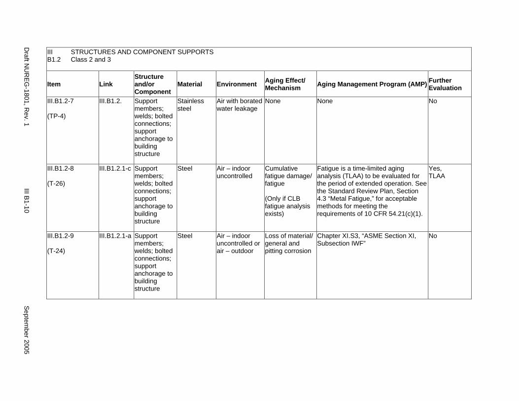
III STRUCTURES AND COMPONENT SUPPORTS B1.2 Class 2 and 3
Item Link Structure and/or Component
Material Environment Aging Effect/ Mechanism Aging Management Program (AMP) Further
Evaluation
III.B1.2-7
(TP-4)
III.B1.2. Support members; welds; bolted connections; support anchorage to building structure
Stainless steel
Air with borated water leakage
None None No
III.B1.2-8
(T-26)
III.B1.2.1-c Support members; welds; bolted connections; support anchorage to building structure
Steel Air – indoor uncontrolled
Cumulative fatigue damage/ fatigue
(Only if CLB fatigue analysis exists)
Fatigue is a time-limited aging analysis (TLAA) to be evaluated for the period of extended operation. See the Standard Review Plan, Section 4.3 “Metal Fatigue,” for acceptable methods for meeting the requirements of 10 CFR 54.21(c)(1).
Yes, TLAA
III.B1.2-9
(T-24)
III.B1.2.1-a Support members; welds; bolted connections; support anchorage to building structure
Steel Air – indoor uncontrolled or air – outdoor
Loss of material/ general and pitting corrosion
Chapter XI.S3, “ASME Section XI, Subsection IWF”
No
Draft N
UR
EG-1801, R
ev. 1 III B
1-10 S
eptember 2005
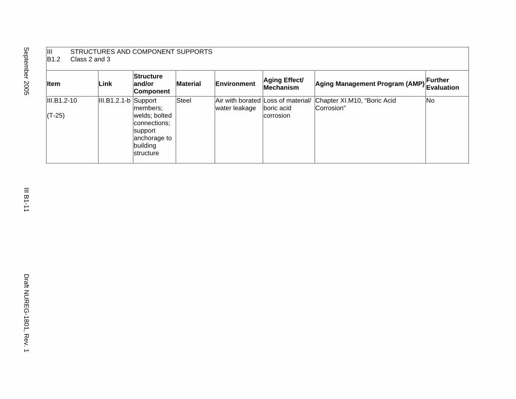
III STRUCTURES AND COMPONENT SUPPORTS B1.2 Class 2 and 3
Item Link Structure and/or Component
Material Environment Aging Effect/ Mechanism Aging Management Program (AMP) Further
Evaluation
III.B1.2-10
(T-25)
III.B1.2.1-b Support members; welds; bolted connections; support anchorage to building structure
Steel Air with borated water leakage
Loss of material/ boric acid corrosion
Chapter XI.M10, “Boric Acid Corrosion”
No
Septem
ber 2005 III B
1-11 D
raft NU
REG
-1801, Rev. 1
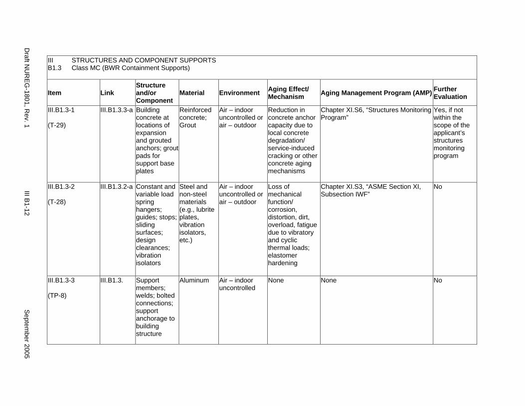
III STRUCTURES AND COMPONENT SUPPORTS B1.3 Class MC (BWR Containment Supports)
Item Link Structure and/or Component
Material Environment Aging Effect/ Mechanism Aging Management Program (AMP) Further
Evaluation
III.B1.3-1
(T-29)
III.B1.3.3-a Building concrete at locations of expansion and grouted anchors; grout pads for support base plates
Reinforced concrete; Grout
Air – indoor uncontrolled or air – outdoor
Reduction in concrete anchor capacity due to local concrete degradation/ service-induced cracking or other concrete aging mechanisms
Chapter XI.S6, “Structures Monitoring Program”
Yes, if not within the scope of the applicant’s structures monitoring program
III.B1.3-2
(T-28)
III.B1.3.2-a Constant and variable load spring hangers; guides; stops; sliding surfaces; design clearances; vibration isolators
Steel and non-steel materials (e.g., lubrite plates, vibration isolators, etc.)
Air – indoor uncontrolled or air – outdoor
Loss of mechanical function/ corrosion, distortion, dirt, overload, fatigue due to vibratory and cyclic thermal loads; elastomer hardening
Chapter XI.S3, “ASME Section XI, Subsection IWF”
No
III.B1.3-3
(TP-8)
III.B1.3. Support members; welds; bolted connections; support anchorage to building structure
Aluminum Air – indoor uncontrolled
None None No
Draft N
UR
EG-1801, R
ev. 1 III B
1-12 S
eptember 2005
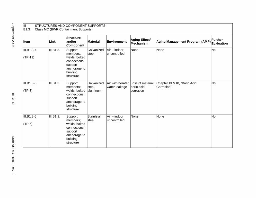
III STRUCTURES AND COMPONENT SUPPORTS B1.3 Class MC (BWR Containment Supports)
Item Link Structure and/or Component
Material Environment Aging Effect/ Mechanism Aging Management Program (AMP) Further
Evaluation
III.B1.3-4
(TP-11)
III.B1.3. Support members; welds; bolted connections; support anchorage to building structure
Galvanized steel
Air – indoor uncontrolled
None None No
III.B1.3-5
(TP-3)
III.B1.3. Support members; welds; bolted connections; support anchorage to building structure
Galvanized steel, aluminum
Air with borated water leakage
Loss of material/ boric acid corrosion
Chapter XI.M10, “Boric Acid Corrosion”
No
III.B1.3-6
(TP-5)
III.B1.3. Support members; welds; bolted connections; support anchorage to building structure
Stainless steel
Air – indoor uncontrolled
None None No
Septem
ber 2005 III B
1-13 D
raft NU
REG
-1801, Rev. 1
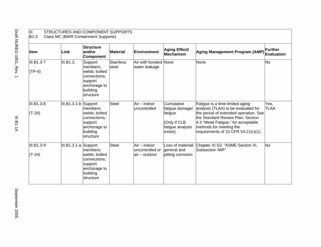
III STRUCTURES AND COMPONENT SUPPORTS B1.3 Class MC (BWR Containment Supports)
Item Link Structure and/or Component
Material Environment Aging Effect/ Mechanism Aging Management Program (AMP) Further
Evaluation
III.B1.3-7
(TP-4)
III.B1.3. Support members; welds; bolted connections; support anchorage to building structure
Stainless steel
Air with borated water leakage
None None No
III.B1.3-8
(T-26)
III.B1.3.1-b Support members; welds; bolted connections; support anchorage to building structure
Steel Air – indoor uncontrolled
Cumulative fatigue damage/ fatigue
(Only if CLB fatigue analysis exists)
Fatigue is a time-limited aging analysis (TLAA) to be evaluated for the period of extended operation. See the Standard Review Plan, Section 4.3 “Metal Fatigue,” for acceptable methods for meeting the requirements of 10 CFR 54.21(c)(1).
Yes, TLAA
III.B1.3-9
(T-24)
III.B1.3.1-a Support members; welds; bolted connections; support anchorage to building structure
Steel Air – indoor uncontrolled or air – outdoor
Loss of material/ general and pitting corrosion
Chapter XI.S3, “ASME Section XI, Subsection IWF”
No
Draft N
UR
EG-1801, R
ev. 1 III B
1-14 S
eptember 2005
B2. SUPPORTS FOR CABLE TRAYS, CONDUIT, HVAC DUCTS, TUBETRACK, INSTRUMENT TUBING, NON-ASME PIPING AND COMPONENTS
Systems, Structures, and Components
This section addresses supports and anchorage for cable trays, conduit, heating, ventilation, and air-conditioning (HVAC) ducts, tube track, instrument tubing, and non-ASME piping and components. Applicable aging effects are identified and the aging management review is presented for each applicable combination of support component and aging effect.
System Interfaces
Physical interfaces exist with the structure, system, or component being supported and with the building structural element to which the support is anchored. A primary function of supports is to provide anchorage of the supported element for internal and external design basis events, so that the supported element can perform its intended function.
September 2005 III B2-1 Draft NUREG-1801, Rev. 1
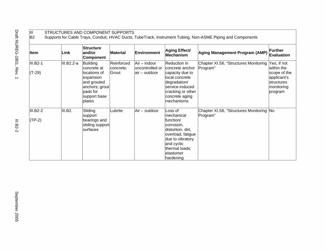
III B2
STRUCTURES AND COMPONENT SUPPORTS Supports for Cable Trays, Conduit, HVAC Ducts, TubeTrack, Instrument Tubing, Non-ASME Piping and Components
Item Link Structure and/or Component
Material Environment Aging Effect/ Mechanism Aging Management Program (AMP) Further
Evaluation
III.B2-1
(T-29)
III.B2.2-a Building concrete at locations of expansion and grouted anchors; grout pads for support base plates
Reinforced concrete; Grout
Air – indoor uncontrolled or air – outdoor
Reduction in concrete anchor capacity due to local concrete degradation/ service-induced cracking or other concrete aging mechanisms
Chapter XI.S6, “Structures Monitoring Program”
Yes, if not within the scope of the applicant’s structures monitoring program
III.B2-2
(TP-2)
III.B2. Sliding support bearings and sliding support surfaces
Lubrite Air – outdoor Loss of mechanical function/ corrosion, distortion, dirt, overload, fatigue due to vibratory and cyclic thermal loads; elastomer hardening
Chapter XI.S6, “Structures Monitoring Program”
No
Draft N
UR
EG-1801, R
ev. 1 III B
2-2 S
eptember 2005
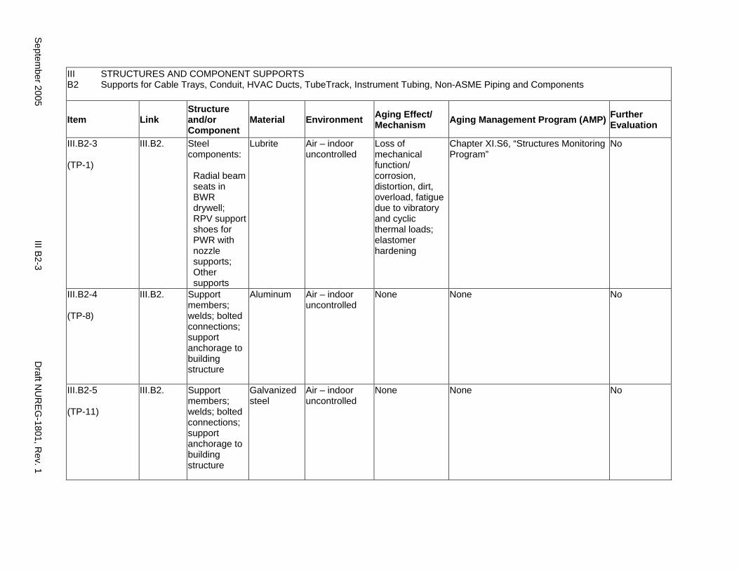
III B2
STRUCTURES AND COMPONENT SUPPORTS Supports for Cable Trays, Conduit, HVAC Ducts, TubeTrack, Instrument Tubing, Non-ASME Piping and Components
Item Link Structure and/or Component
Material Environment Aging Effect/ Mechanism Aging Management Program (AMP) Further
Evaluation
III.B2-3
(TP-1)
III.B2. Steel components:
Radial beam seats in BWR drywell; RPV support shoes for PWR with nozzle supports; Other supports
Lubrite Air – indoor uncontrolled
Loss of mechanical function/ corrosion, distortion, dirt, overload, fatigue due to vibratory and cyclic thermal loads; elastomer hardening
Chapter XI.S6, “Structures Monitoring Program”
No
III.B2-4
(TP-8)
III.B2. Support members; welds; bolted connections; support anchorage to building structure
Aluminum Air – indoor uncontrolled
None None No
III.B2-5
(TP-11)
III.B2. Support members; welds; bolted connections; support anchorage to building structure
Galvanized steel
Air – indoor uncontrolled
None None No
Septem
ber 2005 III B
2-3 D
raft NU
REG
-1801, Rev. 1
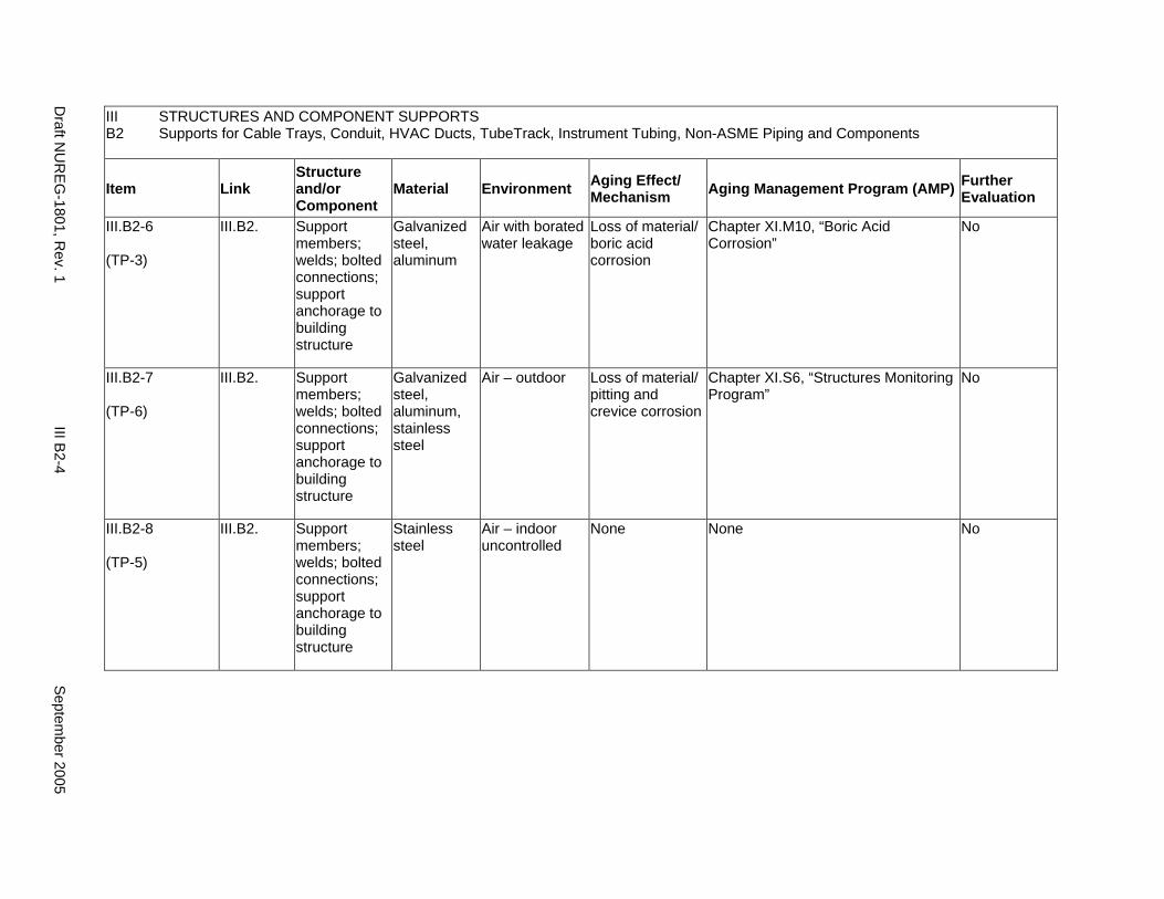
III B2
STRUCTURES AND COMPONENT SUPPORTS Supports for Cable Trays, Conduit, HVAC Ducts, TubeTrack, Instrument Tubing, Non-ASME Piping and Components
Item Link Structure and/or Component
Material Environment Aging Effect/ Mechanism Aging Management Program (AMP) Further
Evaluation
III.B2-6
(TP-3)
III.B2. Support members; welds; bolted connections; support anchorage to building structure
Galvanized steel, aluminum
Air with borated water leakage
Loss of material/ boric acid corrosion
Chapter XI.M10, “Boric Acid Corrosion”
No
III.B2-7
(TP-6)
III.B2. Support members; welds; bolted connections; support anchorage to building structure
Galvanized steel, aluminum, stainless steel
Air – outdoor Loss of material/ pitting and crevice corrosion
Chapter XI.S6, “Structures Monitoring Program”
No
III.B2-8
(TP-5)
III.B2. Support members; welds; bolted connections; support anchorage to building structure
Stainless steel
Air – indoor uncontrolled
None None No
Draft N
UR
EG-1801, R
ev. 1 III B
2-4 S
eptember 2005
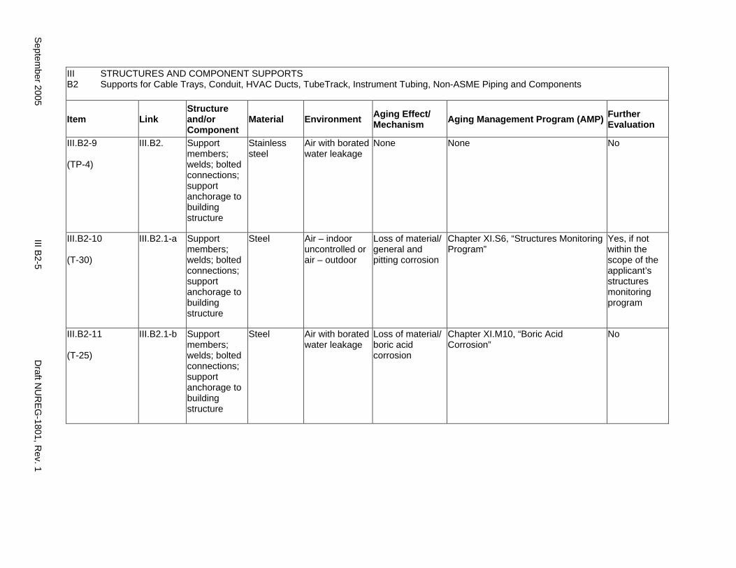
III STRUCTURES AND COMPONENT SUPPORTS B2 Supports for Cable Trays, Conduit, HVAC Ducts, TubeTrack, Instrument Tubing, Non-ASME Piping and Components
Item Link Structure and/or Component
Material Environment Aging Effect/ Mechanism Aging Management Program (AMP) Further
Evaluation
III.B2-9
(TP-4)
III.B2. Support members; welds; bolted connections; support anchorage to building structure
Stainless steel
Air with borated water leakage
None None No
III.B2-10
(T-30)
III.B2.1-a Support members; welds; bolted connections; support anchorage to building structure
Steel Air – indoor uncontrolled or air – outdoor
Loss of material/ general and pitting corrosion
Chapter XI.S6, “Structures Monitoring Program”
Yes, if not within the scope of the applicant’s structures monitoring program
III.B2-11
(T-25)
III.B2.1-b Support members; welds; bolted connections; support anchorage to building structure
Steel Air with borated water leakage
Loss of material/ boric acid corrosion
Chapter XI.M10, “Boric Acid Corrosion”
No
Septem
ber 2005 III B
2-5 D
raft NU
REG
-1801, Rev. 1

This Page Intentionally Left Blank
Draft NUREG-1801, Rev. 1 III B2-6 September 2005
B3. ANCHORAGE OF RACKS, PANELS, CABINETS, AND ENCLOSURES FOR ELECTRICAL EQUIPMENT AND INSTRUMENTATION
Systems, Structures, and Components
This section addresses supports and anchorage for racks, panels, cabinets, and enclosures for electrical equipment and instrumentation. Applicable aging effects are identified and the aging management review is presented for each applicable combination of support component and aging effect.
System Interfaces
Physical interfaces exist with the structure, system, or component being supported and with the building structural element to which the support is anchored. A primary function of supports is to provide anchorage of the supported element for internal and external design basis events, so that the supported element can perform its intended function.
September 2005 III B3-1 Draft NUREG-1801, Rev. 1
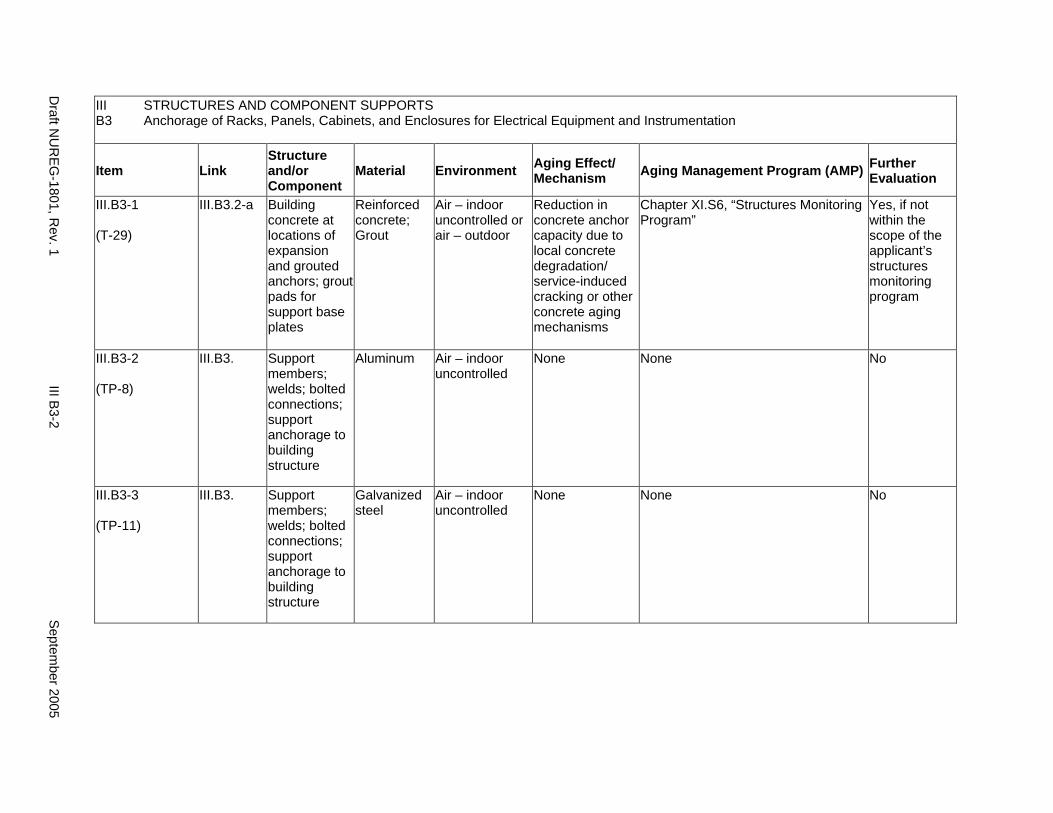
III B3
STRUCTURES AND COMPONENT SUPPORTS Anchorage of Racks, Panels, Cabinets, and Enclosures for Electrical Equipment and Instrumentation
Item Link Structure and/or Component
Material Environment Aging Effect/ Mechanism Aging Management Program (AMP) Further
Evaluation
III.B3-1
(T-29)
III.B3.2-a Building concrete at locations of expansion and grouted anchors; grout pads for support base plates
Reinforced concrete; Grout
Air – indoor uncontrolled or air – outdoor
Reduction in concrete anchor capacity due to local concrete degradation/ service-induced cracking or other concrete aging mechanisms
Chapter XI.S6, “Structures Monitoring Program”
Yes, if not within the scope of the applicant’s structures monitoring program
III.B3-2
(TP-8)
III.B3. Support members; welds; bolted connections; support anchorage to building structure
Aluminum Air – indoor uncontrolled
None None No
III.B3-3
(TP-11)
III.B3. Support members; welds; bolted connections; support anchorage to building structure
Galvanized steel
Air – indoor uncontrolled
None None No
Draft N
UR
EG-1801, R
ev. 1 III B
3-2 S
eptember 2005
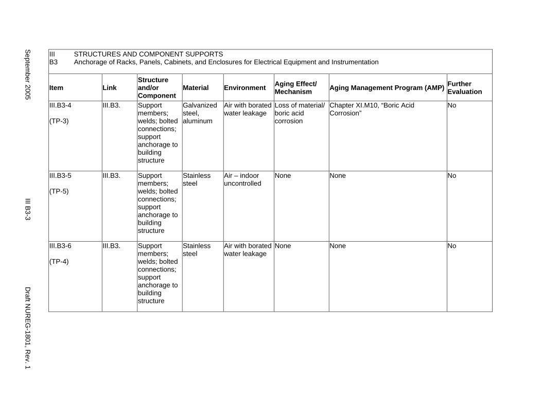
III B3
STRUCTURES AND COMPONENT SUPPORTS Anchorage of Racks, Panels, Cabinets, and Enclosures for Electrical Equipment and Instrumentation
Item Link Structure and/or Component
Material Environment Aging Effect/ Mechanism Aging Management Program (AMP) Further
Evaluation
III.B3-4
(TP-3)
III.B3. Support members; welds; bolted connections; support anchorage to building structure
Galvanized steel, aluminum
Air with borated water leakage
Loss of material/ boric acid corrosion
Chapter XI.M10, “Boric Acid Corrosion”
No
III.B3-5
(TP-5)
III.B3. Support members; welds; bolted connections; support anchorage to building structure
Stainless steel
Air – indoor uncontrolled
None None No
III.B3-6
(TP-4)
III.B3. Support members; welds; bolted connections; support anchorage to building structure
Stainless steel
Air with borated water leakage
None None No
Septem
ber 2005 III B
3-3 D
raft NU
REG
-1801, Rev. 1
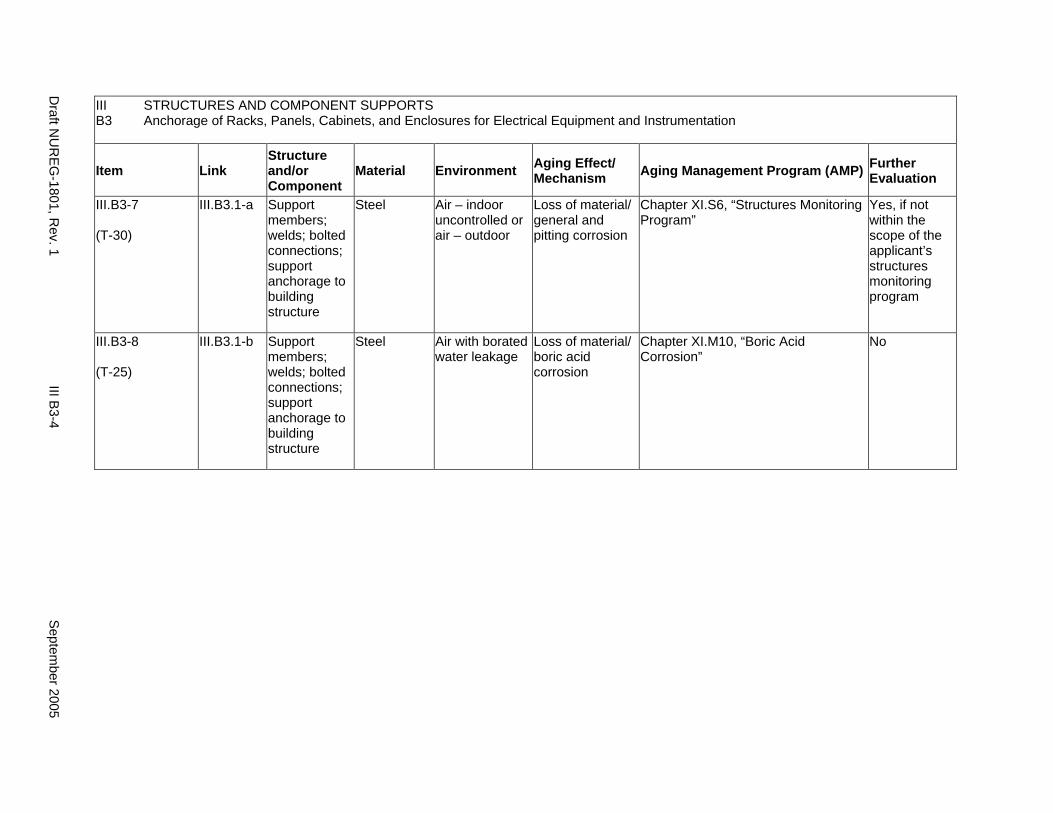
III B3
STRUCTURES AND COMPONENT SUPPORTS Anchorage of Racks, Panels, Cabinets, and Enclosures for Electrical Equipment and Instrumentation
Item Link Structure and/or Component
Material Environment Aging Effect/ Mechanism Aging Management Program (AMP) Further
Evaluation
III.B3-7
(T-30)
III.B3.1-a Support members; welds; bolted connections; support anchorage to building structure
Steel Air – indoor uncontrolled or air – outdoor
Loss of material/ general and pitting corrosion
Chapter XI.S6, “Structures Monitoring Program”
Yes, if not within the scope of the applicant’s structures monitoring program
III.B3-8
(T-25)
III.B3.1-b Support members; welds; bolted connections; support anchorage to building structure
Steel Air with borated water leakage
Loss of material/ boric acid corrosion
Chapter XI.M10, “Boric Acid Corrosion”
No
Draft N
UR
EG-1801, R
ev. 1 III B
3-4 S
eptember 2005
B4. SUPPORTS FOR EMERGENCY DIESEL GENERATOR (EDG), HVAC SYSTEM COMPONENTS, AND OTHER MISCELLANEOUS MECHANICAL EQUIPMENT
Systems, Structures, and Components
This section addresses supports and anchorage for the emergency diesel generator (EDG) and HVAC system components, and other miscellaneous mechanical equipment. Applicable aging effects are identified and the aging management review is presented for each applicable combination of support component and aging effect.
System Interfaces
Physical interfaces exist with the structure, system, or component being supported and with the building structural element to which the support is anchored. A primary function of supports is to provide anchorage of the supported element for internal and external design basis events, so that the supported element can perform its intended function.
September 2005 III B4-1 Draft NUREG-1801, Rev. 1
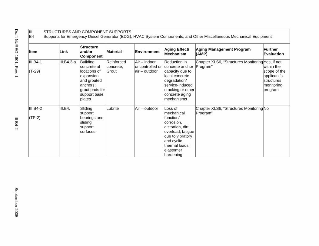
III B4
STRUCTURES AND COMPONENT SUPPORTS Supports for Emergency Diesel Generator (EDG), HVAC System Components, and Other Miscellaneous Mechanical Equipment
Item Link Structure and/or Component
Material Environment Aging Effect/ Mechanism
Aging Management Program (AMP)
Further Evaluation
III.B4-1
(T-29)
III.B4.3-a Building concrete at locations of expansion and grouted anchors; grout pads for support base plates
Reinforced concrete; Grout
Air – indoor uncontrolled or air – outdoor
Reduction in concrete anchor capacity due to local concrete degradation/ service-induced cracking or other concrete aging mechanisms
Chapter XI.S6, “Structures Monitoring Program”
Yes, if not within the scope of the applicant’s structures monitoring program
III.B4-2
(TP-2)
III.B4. Sliding support bearings and sliding support surfaces
Lubrite Air – outdoor Loss of mechanical function/ corrosion, distortion, dirt, overload, fatigue due to vibratory and cyclic thermal loads; elastomer hardening
Chapter XI.S6, “Structures Monitoring Program”
No
Draft N
UR
EG-1801, R
ev. 1 III B
4-2 S
eptember 2005
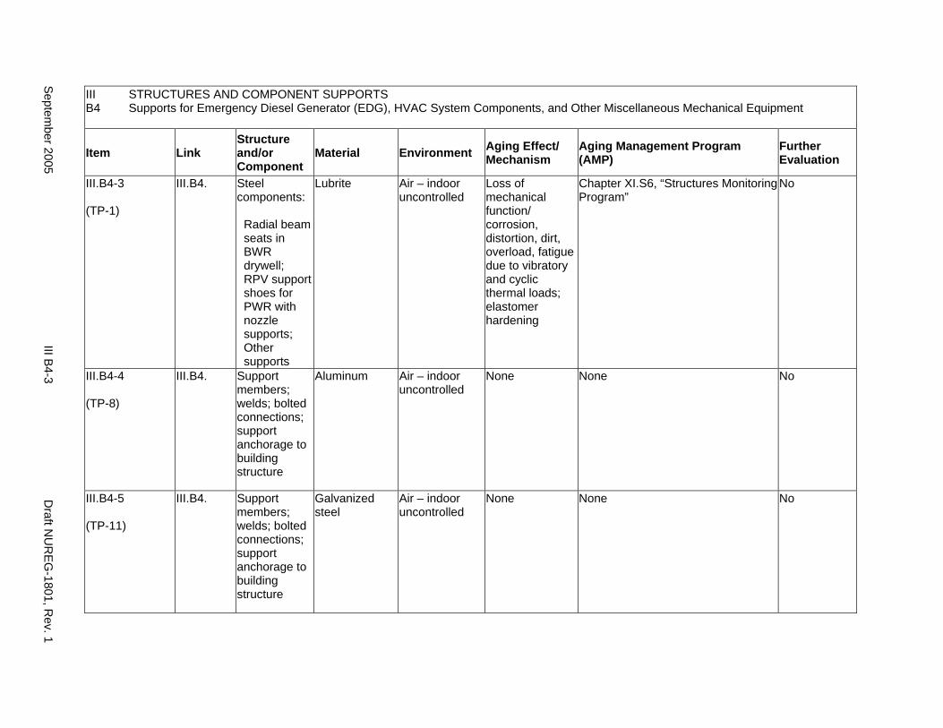
III B4
STRUCTURES AND COMPONENT SUPPORTS Supports for Emergency Diesel Generator (EDG), HVAC System Components, and Other Miscellaneous Mechanical Equipment
Item Link Structure and/or Component
Material Environment Aging Effect/ Mechanism
Aging Management Program (AMP)
Further Evaluation
III.B4-3
(TP-1)
III.B4. Steel components:
Radial beam seats in BWR drywell; RPV support shoes for PWR with nozzle supports; Other supports
Lubrite Air – indoor uncontrolled
Loss of mechanical function/ corrosion, distortion, dirt, overload, fatigue due to vibratory and cyclic thermal loads; elastomer hardening
Chapter XI.S6, “Structures Monitoring Program”
No
III.B4-4
(TP-8)
III.B4. Support members; welds; bolted connections; support anchorage to building structure
Aluminum Air – indoor uncontrolled
None None No
III.B4-5
(TP-11)
III.B4. Support members; welds; bolted connections; support anchorage to building structure
Galvanized steel
Air – indoor uncontrolled
None None No
Septem
ber 2005 III B
4-3 D
raft NU
REG
-1801, Rev. 1
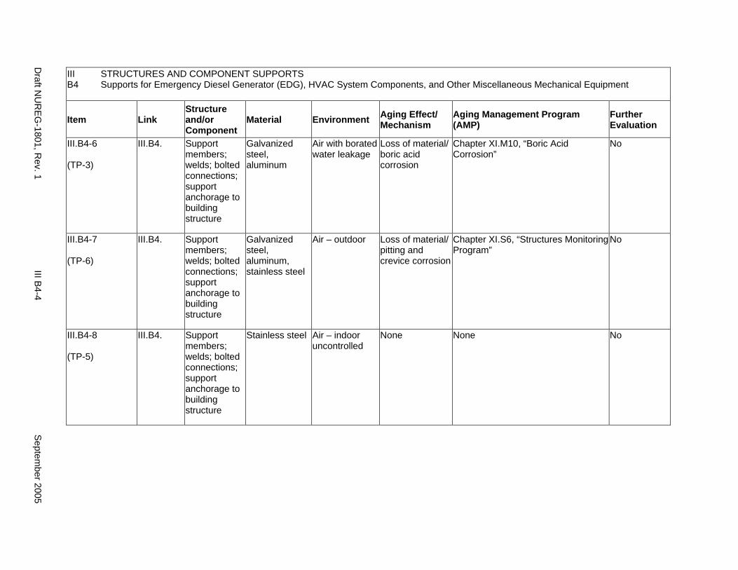
III B4
STRUCTURES AND COMPONENT SUPPORTS Supports for Emergency Diesel Generator (EDG), HVAC System Components, and Other Miscellaneous Mechanical Equipment
Item Link Structure and/or Component
Material Environment Aging Effect/ Mechanism
Aging Management Program (AMP)
Further Evaluation
III.B4-6
(TP-3)
III.B4. Support members; welds; bolted connections; support anchorage to building structure
Galvanized steel, aluminum
Air with borated water leakage
Loss of material/ boric acid corrosion
Chapter XI.M10, “Boric Acid Corrosion”
No
III.B4-7
(TP-6)
III.B4. Support members; welds; bolted connections; support anchorage to building structure
Galvanized steel, aluminum, stainless steel
Air – outdoor Loss of material/ pitting and crevice corrosion
Chapter XI.S6, “Structures Monitoring Program”
No
III.B4-8
(TP-5)
III.B4. Support members; welds; bolted connections; support anchorage to building structure
Stainless steel Air – indoor uncontrolled
None None No
Draft N
UR
EG-1801, R
ev. 1 III B
4-4 S
eptember 2005
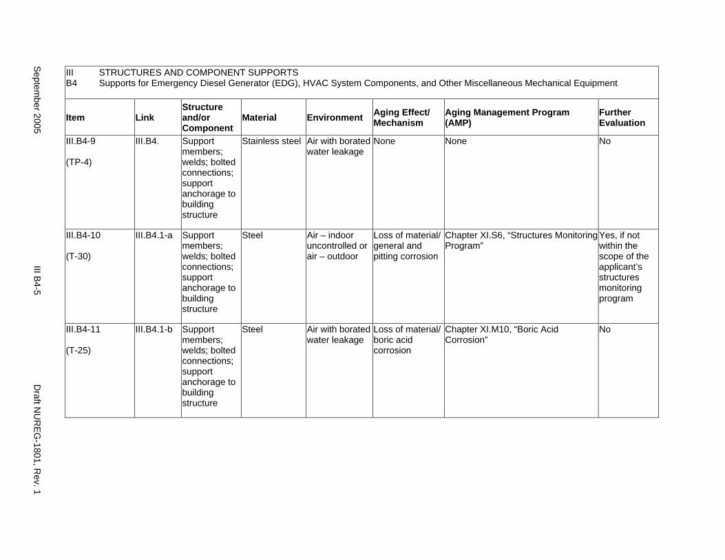
III STRUCTURES AND COMPONENT SUPPORTS B4 Supports for Emergency Diesel Generator (EDG), HVAC System Components, and Other Miscellaneous Mechanical Equipment
Item Link Structure and/or Component
Material Environment Aging Effect/ Mechanism
Aging Management Program (AMP)
Further Evaluation
III.B4-9
(TP-4)
III.B4. Support members; welds; bolted connections; support anchorage to building structure
Stainless steel Air with borated water leakage
None None No
III.B4-10
(T-30)
III.B4.1-a Support members; welds; bolted connections; support anchorage to building structure
Steel Air – indoor uncontrolled or air – outdoor
Loss of material/ general and pitting corrosion
Chapter XI.S6, “Structures Monitoring Program”
Yes, if not within the scope of the applicant’s structures monitoring program
III.B4-11
(T-25)
III.B4.1-b Support members; welds; bolted connections; support anchorage to building structure
Steel Air with borated water leakage
Loss of material/ boric acid corrosion
Chapter XI.M10, “Boric Acid Corrosion”
No
Septem
ber 2005 III B
4-5 D
raft NU
REG
-1801, Rev. 1
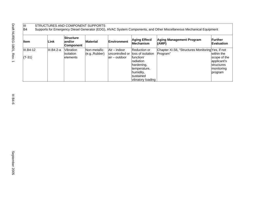
III STRUCTURES AND COMPONENT SUPPORTS B4 Supports for Emergency Diesel Generator (EDG), HVAC System Components, and Other Miscellaneous Mechanical Equipment
Item Link Structure and/or Component
Material Environment Aging Effect/ Mechanism
Aging Management Program (AMP)
Further Evaluation
III.B4-12
(T-31)
III.B4.2-a Vibration isolation elements
Non-metallic (e.g.,Rubber)
Air – indoor uncontrolled or air – outdoor
Reduction or loss of isolation function/ radiation hardening, temperature, humidity, sustained vibratory loading
Chapter XI.S6, “Structures Monitoring Program”
Yes, if not within the scope of the applicant’s structures monitoring program
Draft N
UR
EG-1801, R
ev. 1 III B
4-6 S
eptember 2005
B5. SUPPORTS FOR PLATFORMS, PIPE WHIP RESTRAINTS, JET IMPINGEMENT SHIELDS, MASONRY WALLS, AND OTHER MISCELLANEOUS STRUCTURES
Systems, Structures, and Components
This section addresses supports and anchorage for platforms, pipe whip restraints, jet impingement shields, masonry walls, and other miscellaneous structures. Applicable aging effects are identified and the aging management review is presented for each applicable combination of support component and aging effect.
System Interfaces
Physical interfaces exist with the structure, system, or component being supported and with the building structural element to which the support is anchored. A primary function of supports is to provide anchorage of the supported element for internal and external design basis events, so that the supported element can perform its intended function.
September 2005 III B5-1 Draft NUREG-1801, Rev. 1
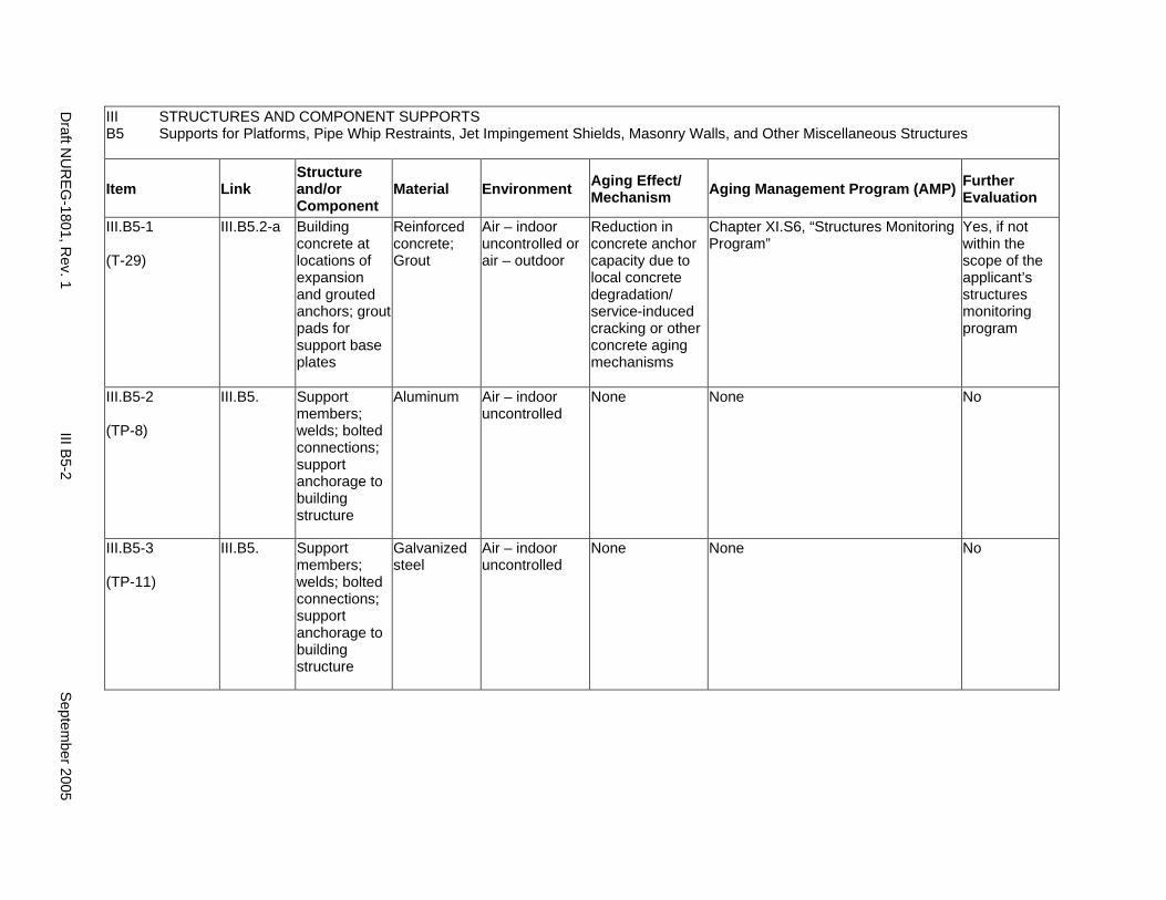
III B5
STRUCTURES AND COMPONENT SUPPORTS Supports for Platforms, Pipe Whip Restraints, Jet Impingement Shields, Masonry Walls, and Other Miscellaneous Structures
Item Link Structure and/or Component
Material Environment Aging Effect/ Mechanism Aging Management Program (AMP) Further
Evaluation
III.B5-1
(T-29)
III.B5.2-a Building concrete at locations of expansion and grouted anchors; grout pads for support base plates
Reinforced concrete; Grout
Air – indoor uncontrolled or air – outdoor
Reduction in concrete anchor capacity due to local concrete degradation/ service-induced cracking or other concrete aging mechanisms
Chapter XI.S6, “Structures Monitoring Program”
Yes, if not within the scope of the applicant’s structures monitoring program
III.B5-2
(TP-8)
III.B5. Support members; welds; bolted connections; support anchorage to building structure
Aluminum Air – indoor uncontrolled
None None No
III.B5-3
(TP-11)
III.B5. Support members; welds; bolted connections; support anchorage to building structure
Galvanized steel
Air – indoor uncontrolled
None None No
Draft N
UR
EG-1801, R
ev. 1 III B
5-2 S
eptember 2005
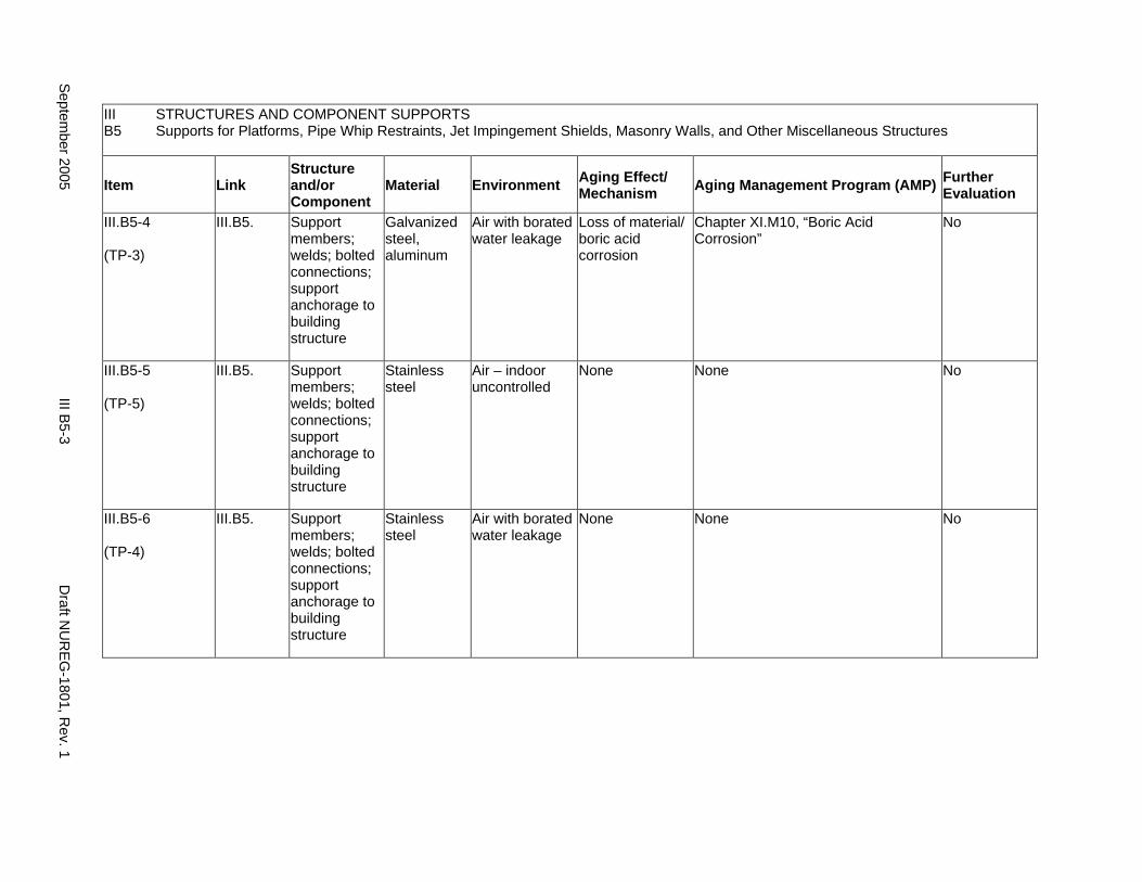
III B5
STRUCTURES AND COMPONENT SUPPORTS Supports for Platforms, Pipe Whip Restraints, Jet Impingement Shields, Masonry Walls, and Other Miscellaneous Structures
Item Link Structure and/or Component
Material Environment Aging Effect/ Mechanism Aging Management Program (AMP) Further
Evaluation
III.B5-4
(TP-3)
III.B5. Support members; welds; bolted connections; support anchorage to building structure
Galvanized steel, aluminum
Air with borated water leakage
Loss of material/ boric acid corrosion
Chapter XI.M10, “Boric Acid Corrosion”
No
III.B5-5
(TP-5)
III.B5. Support members; welds; bolted connections; support anchorage to building structure
Stainless steel
Air – indoor uncontrolled
None None No
III.B5-6
(TP-4)
III.B5. Support members; welds; bolted connections; support anchorage to building structure
Stainless steel
Air with borated water leakage
None None No
Septem
ber 2005 III B
5-3 D
raft NU
REG
-1801, Rev. 1
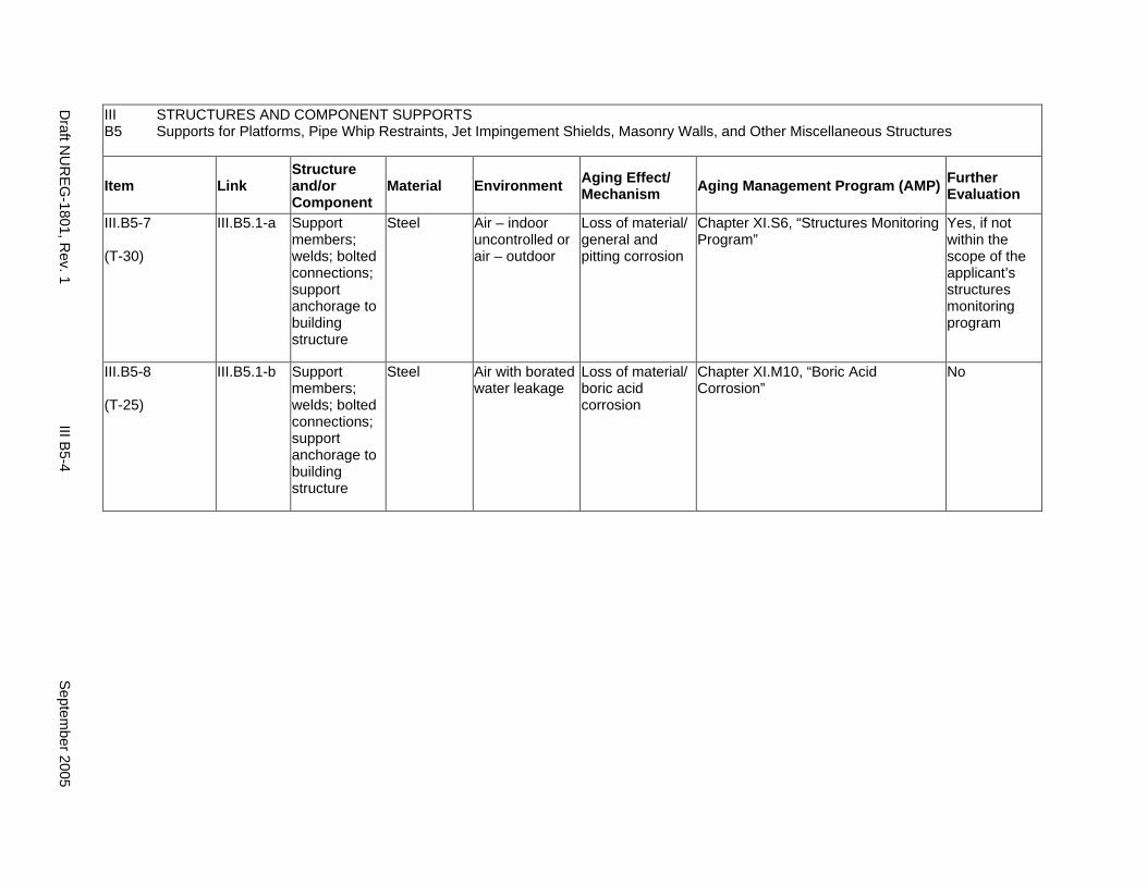
III B5
STRUCTURES AND COMPONENT SUPPORTS Supports for Platforms, Pipe Whip Restraints, Jet Impingement Shields, Masonry Walls, and Other Miscellaneous Structures
Item Link Structure and/or Component
Material Environment Aging Effect/ Mechanism Aging Management Program (AMP) Further
Evaluation
III.B5-7
(T-30)
III.B5.1-a Support members; welds; bolted connections; support anchorage to building structure
Steel Air – indoor uncontrolled or air – outdoor
Loss of material/ general and pitting corrosion
Chapter XI.S6, “Structures Monitoring Program”
Yes, if not within the scope of the applicant’s structures monitoring program
III.B5-8
(T-25)
III.B5.1-b Support members; welds; bolted connections; support anchorage to building structure
Steel Air with borated water leakage
Loss of material/ boric acid corrosion
Chapter XI.M10, “Boric Acid Corrosion”
No
Draft N
UR
EG-1801, R
ev. 1 III B
5-4 S
eptember 2005
CHAPTER IV
REACTOR VESSEL, INTERNALS, AND REACTOR COOLANT SYSTEM
September 2005 IV-i Draft NUREG-1801, Rev. 1

This Page Intentionally Left Blank
Draft NUREG-1801, Rev. 1 IV-ii September 2005
MAJOR PLANT SECTIONS
A1. Reactor Vessel (Boiling Water Reactor)
A2. Reactor Vessel (Pressurized Water Reactor)
B1. Reactor Vessel Internals (Boiling Water Reactor)
B2. Reactor Vessel Internals (PWR) - Westinghouse
B3. Reactor Vessel Internals (PWR) - Combustion Engineering
B4. Reactor Vessel Internals (PWR) - Babcock and Wilcox
C1. Reactor Coolant Pressure Boundary (Boiling Water Reactor)
C2. Reactor Coolant System and Connected Lines (Pressurized Water Reactor)
D1. Steam Generator (Recirculating)
D2. Steam Generator (Once-Through)
E. Common Miscellaneous Material/Environment Combinations
September 2005 IV-iii Draft NUREG-1801, Rev. 1

This Page Intentionally Left Blank
Draft NUREG-1801, Rev. 1 IV-iv September 2005
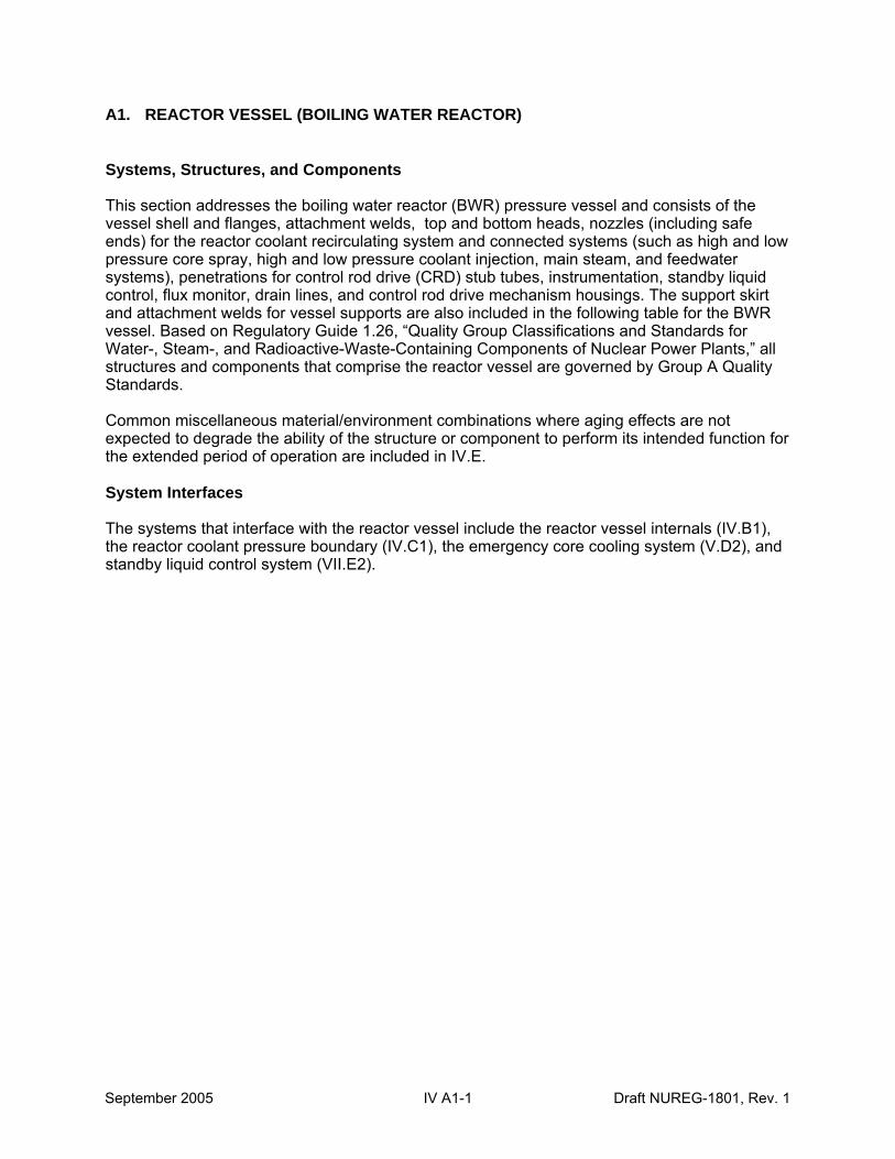
A1. REACTOR VESSEL (BOILING WATER REACTOR)
Systems, Structures, and Components
This section addresses the boiling water reactor (BWR) pressure vessel and consists of the vessel shell and flanges, attachment welds, top and bottom heads, nozzles (including safe ends) for the reactor coolant recirculating system and connected systems (such as high and low pressure core spray, high and low pressure coolant injection, main steam, and feedwater systems), penetrations for control rod drive (CRD) stub tubes, instrumentation, standby liquid control, flux monitor, drain lines, and control rod drive mechanism housings. The support skirt and attachment welds for vessel supports are also included in the following table for the BWR vessel. Based on Regulatory Guide 1.26, “Quality Group Classifications and Standards for Water-, Steam-, and Radioactive-Waste-Containing Components of Nuclear Power Plants,” all structures and components that comprise the reactor vessel are governed by Group A Quality Standards.
Common miscellaneous material/environment combinations where aging effects are not expected to degrade the ability of the structure or component to perform its intended function for the extended period of operation are included in IV.E.
System Interfaces
The systems that interface with the reactor vessel include the reactor vessel internals (IV.B1), the reactor coolant pressure boundary (IV.C1), the emergency core cooling system (V.D2), and standby liquid control system (VII.E2).
September 2005 IV A1-1 Draft NUREG-1801, Rev. 1
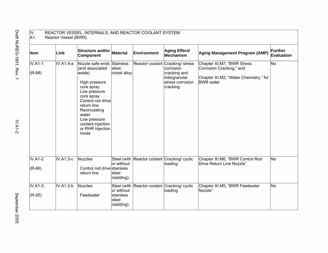
IV REACTOR VESSEL, INTERNALS, AND REACTOR COOLANT SYSTEM A1 Reactor Vessel (BWR)
Item Link Structure and/or Component Material Environment Aging Effect/
Mechanism Aging Management Program (AMP) Further Evaluation
IV.A1-1
(R-68)
IV.A1.4-a Nozzle safe ends (and associated welds)
High pressure core spray Low pressure core spray Control rod drive return line Recirculating water Low pressure coolant injection or RHR injection mode
Stainless steel; nickel alloy
Reactor coolant Cracking/ stress corrosion cracking and intergranular stress corrosion cracking
Chapter XI.M7, “BWR Stress Corrosion Cracking,” and
Chapter XI.M2, “Water Chemistry,” for BWR water
No
IV.A1-2
(R-66)
IV.A1.3-c Nozzles
Control rod drive return line
Steel (with or without stainless steel cladding)
Reactor coolant Cracking/ cyclic loading
Chapter XI.M6, “BWR Control Rod Drive Return Line Nozzle”
No
IV.A1-3
(R-65)
IV.A1.3-b Nozzles
Feedwater
Steel (with or without stainless steel cladding)
Reactor coolant Cracking/ cyclic loading
Chapter XI.M5, “BWR Feedwater Nozzle”
No
Draft N
UR
EG
-1801, Rev. 1
IV.A
1-2 S
eptember 2005
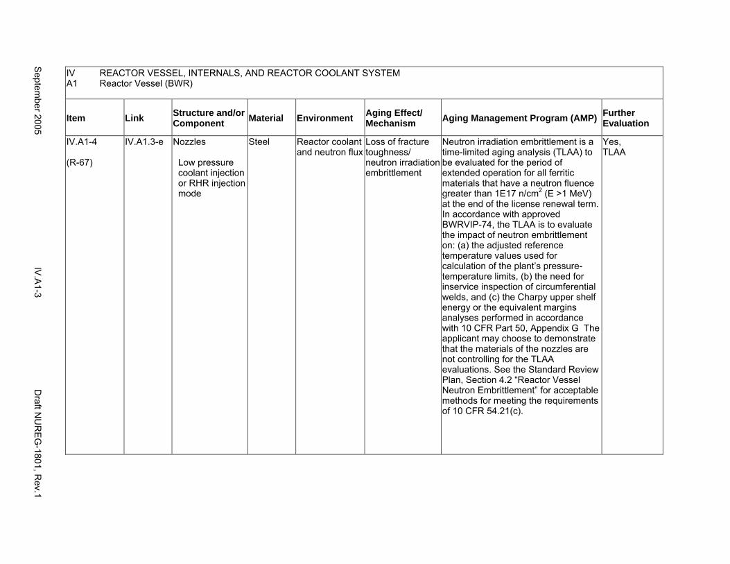
IV A1
REACTOR VESSEL, INTERNALS, AND REACTOR COOLANT SYSTEM Reactor Vessel (BWR)
Item Link Structure and/or Component Material Environment Aging Effect/
Mechanism Aging Management Program (AMP) Further Evaluation
IV.A1-4
(R-67)
IV.A1.3-e Nozzles
Low pressure coolant injection or RHR injection mode
Steel Reactor coolant and neutron flux
Loss of fracture toughness/ neutron irradiation embrittlement
Neutron irradiation embrittlement is a time-limited aging analysis (TLAA) to be evaluated for the period of extended operation for all ferritic materials that have a neutron fluence greater than 1E17 n/cm2 (E >1 MeV) at the end of the license renewal term. In accordance with approved BWRVIP-74, the TLAA is to evaluate the impact of neutron embrittlement on: (a) the adjusted reference temperature values used for calculation of the plant’s pressure-temperature limits, (b) the need for inservice inspection of circumferential welds, and (c) the Charpy upper shelf energy or the equivalent margins analyses performed in accordance with 10 CFR Part 50, Appendix G The applicant may choose to demonstrate that the materials of the nozzles are not controlling for the TLAA evaluations. See the Standard Review Plan, Section 4.2 “Reactor Vessel Neutron Embrittlement” for acceptable methods for meeting the requirements of 10 CFR 54.21(c).
Yes, TLAA
Septem
ber 2005 IV
.A1-3
Draft N
UR
EG
-1801, Rev.1
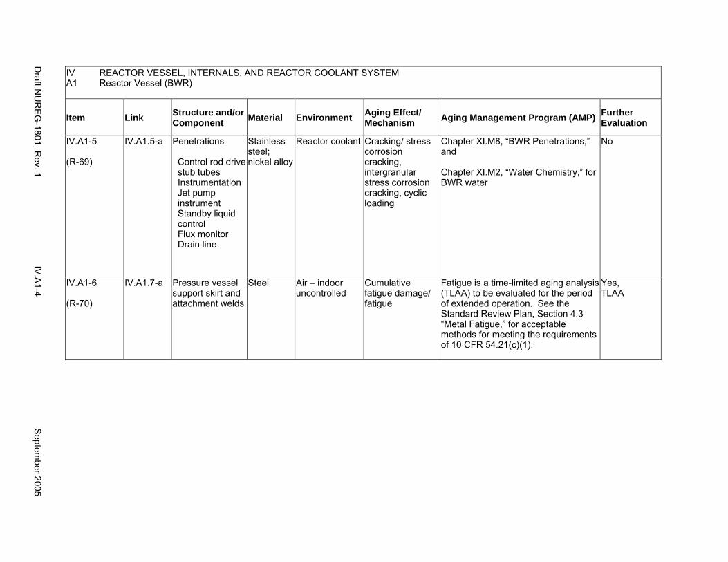
IV REACTOR VESSEL, INTERNALS, AND REACTOR COOLANT SYSTEM A1 Reactor Vessel (BWR)
Item Link Structure and/or Component Material Environment Aging Effect/
Mechanism Aging Management Program (AMP) Further Evaluation
IV.A1-5
(R-69)
IV.A1.5-a Penetrations
Control rod drive stub tubes Instrumentation Jet pump instrument Standby liquid control Flux monitor Drain line
Stainless steel; nickel alloy
Reactor coolant Cracking/ stress corrosion cracking, intergranular stress corrosion cracking, cyclic loading
Chapter XI.M8, “BWR Penetrations,” and
Chapter XI.M2, “Water Chemistry,” for BWR water
No
IV.A1-6
(R-70)
IV.A1.7-a Pressure vessel support skirt and attachment welds
Steel Air – indoor uncontrolled
Cumulative fatigue damage/ fatigue
Fatigue is a time-limited aging analysis (TLAA) to be evaluated for the period of extended operation. See the Standard Review Plan, Section 4.3 “Metal Fatigue,” for acceptable methods for meeting the requirements of 10 CFR 54.21(c)(1).
Yes, TLAA
Draft N
UR
EG
-1801, Rev. 1
IV.A
1-4 S
eptember 2005
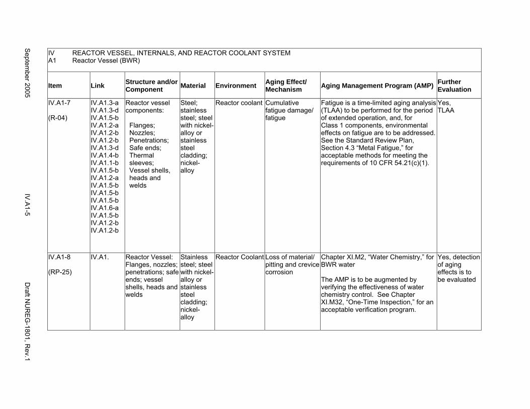
IV A1
REACTOR VESSEL, INTERNALS, AND REACTOR COOLANT SYSTEM Reactor Vessel (BWR)
Item Link Structure and/or Component Material Environment Aging Effect/
Mechanism Aging Management Program (AMP) Further Evaluation
IV.A1-7
(R-04)
IV.A1.3-a IV.A1.3-d IV.A1.5-b IV.A1.2-a IV.A1.2-b IV.A1.2-b IV.A1.3-d IV.A1.4-b IV.A1.1-b IV.A1.5-b IV.A1.2-a IV.A1.5-b IV.A1.5-b IV.A1.5-b IV.A1.6-a IV.A1.5-b IV.A1.2-b IV.A1.2-b
Reactor vessel components:
Flanges; Nozzles; Penetrations; Safe ends; Thermal sleeves; Vessel shells, heads and welds
Steel; stainless steel; steel with nickel-alloy or stainless steel cladding; nickel-alloy
Reactor coolant Cumulative fatigue damage/ fatigue
Fatigue is a time-limited aging analysis (TLAA) to be performed for the period of extended operation, and, for Class 1 components, environmental effects on fatigue are to be addressed. See the Standard Review Plan, Section 4.3 “Metal Fatigue,” for acceptable methods for meeting the requirements of 10 CFR 54.21(c)(1).
Yes, TLAA
IV.A1-8
(RP-25)
IV.A1. Reactor Vessel: Flanges, nozzles; penetrations; safe ends; vessel shells, heads and welds
Stainless steel; steel with nickel-alloy or stainless steel cladding; nickel-alloy
Reactor Coolant Loss of material/ pitting and crevice corrosion
Chapter XI.M2, “Water Chemistry,” for BWR water
The AMP is to be augmented by verifying the effectiveness of water chemistry control. See Chapter XI.M32, “One-Time Inspection,” for an acceptable verification program.
Yes, detection of aging effects is to be evaluated
Septem
ber 2005 IV
.A1-5
Draft N
UR
EG
-1801, Rev.1
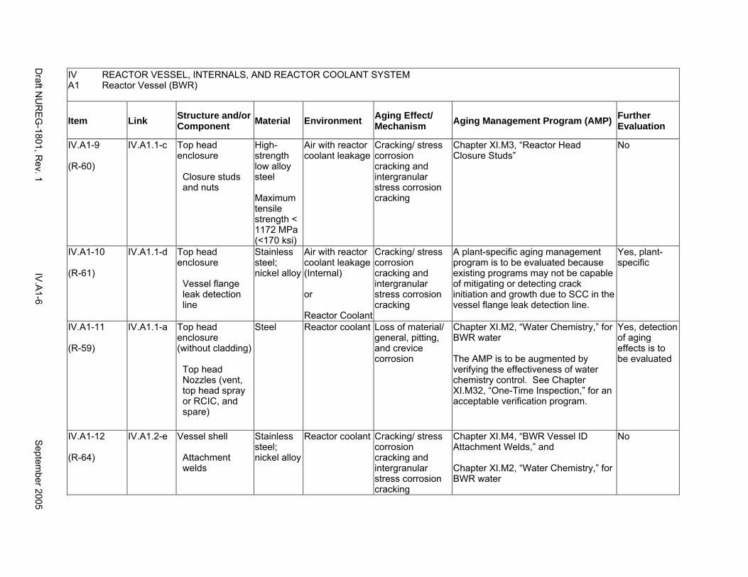
IV REACTOR VESSEL, INTERNALS, AND REACTOR COOLANT SYSTEM A1 Reactor Vessel (BWR)
Item Link Structure and/or Component Material Environment Aging Effect/
Mechanism Aging Management Program (AMP) Further Evaluation
IV.A1-9
(R-60)
IV.A1.1-c Top head enclosure
Closure studs and nuts
High-strength low alloy steel
Maximum tensile strength < 1172 MPa (<170 ksi)
Air with reactor coolant leakage
Cracking/ stress corrosion cracking and intergranular stress corrosion cracking
Chapter XI.M3, “Reactor Head Closure Studs”
No
IV.A1-10
(R-61)
IV.A1.1-d Top head enclosure
Vessel flange leak detection line
Stainless steel; nickel alloy
Air with reactor coolant leakage (Internal)
or
Reactor Coolant
Cracking/ stress corrosion cracking and intergranular stress corrosion cracking
A plant-specific aging management program is to be evaluated because existing programs may not be capable of mitigating or detecting crack initiation and growth due to SCC in the vessel flange leak detection line.
Yes, plant-specific
IV.A1-11
(R-59)
IV.A1.1-a Top head enclosure (without cladding)
Top head Nozzles (vent, top head spray or RCIC, and spare)
Steel Reactor coolant Loss of material/ general, pitting, and crevice corrosion
Chapter XI.M2, “Water Chemistry,” for BWR water
The AMP is to be augmented by verifying the effectiveness of water chemistry control. See Chapter XI.M32, “One-Time Inspection,” for an acceptable verification program.
Yes, detection of aging effects is to be evaluated
IV.A1-12
(R-64)
IV.A1.2-e Vessel shell
Attachment welds
Stainless steel; nickel alloy
Reactor coolant Cracking/ stress corrosion cracking and intergranular stress corrosion cracking
Chapter XI.M4, “BWR Vessel ID Attachment Welds,” and
Chapter XI.M2, “Water Chemistry,” for BWR water
No
Draft N
UR
EG
-1801, Rev. 1
IV.A
1-6 S
eptember 2005
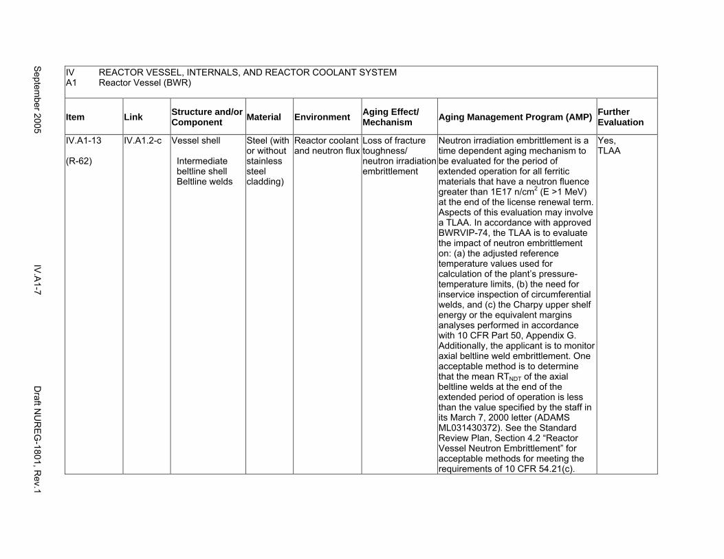
IV REACTOR VESSEL, INTERNALS, AND REACTOR COOLANT SYSTEM A1 Reactor Vessel (BWR)
Item Link Structure and/or Component Material Environment Aging Effect/
Mechanism Aging Management Program (AMP) Further Evaluation
IV.A1-13
(R-62)
IV.A1.2-c Vessel shell
Intermediate beltline shell Beltline welds
Steel (with or without stainless steel cladding)
Reactor coolant and neutron flux
Loss of fracture toughness/ neutron irradiation embrittlement
Neutron irradiation embrittlement is a time dependent aging mechanism to be evaluated for the period of extended operation for all ferritic materials that have a neutron fluence greater than 1E17 n/cm2 (E >1 MeV) at the end of the license renewal term. Aspects of this evaluation may involve a TLAA. In accordance with approved BWRVIP-74, the TLAA is to evaluate the impact of neutron embrittlement on: (a) the adjusted reference temperature values used for calculation of the plant’s pressure-temperature limits, (b) the need for inservice inspection of circumferential welds, and (c) the Charpy upper shelf energy or the equivalent margins analyses performed in accordance with 10 CFR Part 50, Appendix G. Additionally, the applicant is to monitor axial beltline weld embrittlement. One acceptable method is to determine that the mean RTNDT of the axial beltline welds at the end of the extended period of operation is less than the value specified by the staff in its March 7, 2000 letter (ADAMS ML031430372). See the Standard Review Plan, Section 4.2 “Reactor Vessel Neutron Embrittlement” for acceptable methods for meeting the requirements of 10 CFR 54.21(c).
Yes, TLAA
Septem
ber 2005 IV
.A1-7
Draft N
UR
EG
-1801, Rev.1
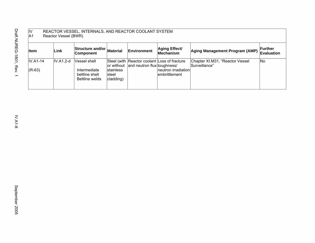
IV REACTOR VESSEL, INTERNALS, AND REACTOR COOLANT SYSTEM A1 Reactor Vessel (BWR)
Item Link Structure and/or Component Material Environment Aging Effect/
Mechanism Aging Management Program (AMP) Further Evaluation
IV.A1-14
(R-63)
IV.A1.2-d Vessel shell
Intermediate beltline shell Beltline welds
Steel (with or without stainless steel cladding)
Reactor coolant and neutron flux
Loss of fracture toughness/ neutron irradiation embrittlement
Chapter XI.M31, “Reactor Vessel Surveillance”
No
Draft N
UR
EG
-1801, Rev. 1
IV.A
1-8 S
eptember 2005
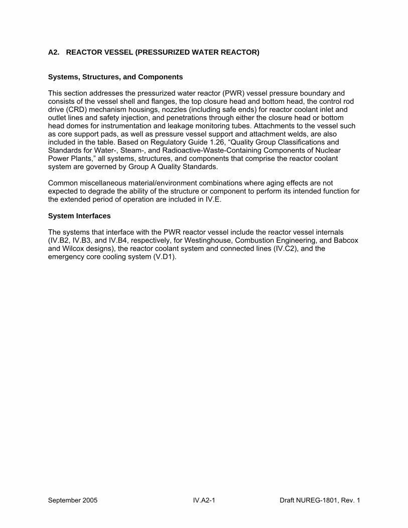
A2. REACTOR VESSEL (PRESSURIZED WATER REACTOR)
Systems, Structures, and Components
This section addresses the pressurized water reactor (PWR) vessel pressure boundary and consists of the vessel shell and flanges, the top closure head and bottom head, the control rod drive (CRD) mechanism housings, nozzles (including safe ends) for reactor coolant inlet and outlet lines and safety injection, and penetrations through either the closure head or bottom head domes for instrumentation and leakage monitoring tubes. Attachments to the vessel such as core support pads, as well as pressure vessel support and attachment welds, are also included in the table. Based on Regulatory Guide 1.26, “Quality Group Classifications and Standards for Water-, Steam-, and Radioactive-Waste-Containing Components of Nuclear Power Plants,” all systems, structures, and components that comprise the reactor coolant system are governed by Group A Quality Standards.
Common miscellaneous material/environment combinations where aging effects are not expected to degrade the ability of the structure or component to perform its intended function for the extended period of operation are included in IV.E.
System Interfaces
The systems that interface with the PWR reactor vessel include the reactor vessel internals (IV.B2, IV.B3, and IV.B4, respectively, for Westinghouse, Combustion Engineering, and Babcox and Wilcox designs), the reactor coolant system and connected lines (IV.C2), and the emergency core cooling system (V.D1).
September 2005 IV.A2-1 Draft NUREG-1801, Rev. 1
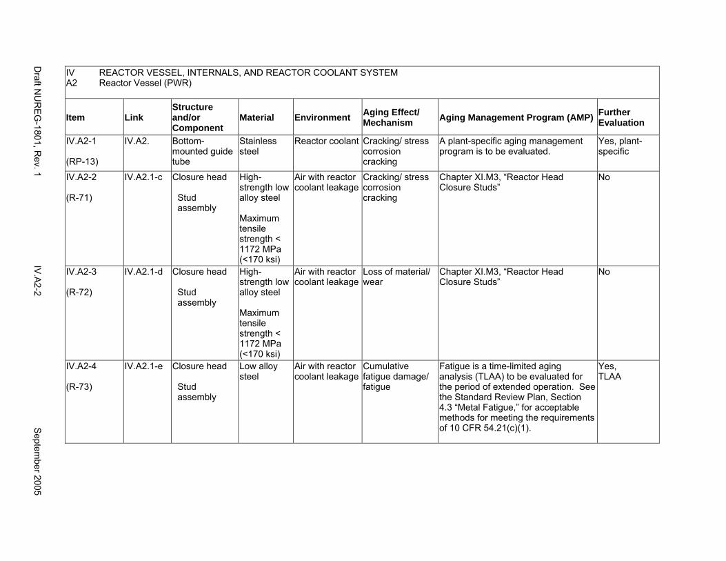
IV REACTOR VESSEL, INTERNALS, AND REACTOR COOLANT SYSTEM A2 Reactor Vessel (PWR)
Item Link Structure and/or Component
Material Environment Aging Effect/ Mechanism Aging Management Program (AMP) Further
Evaluation
IV.A2-1
(RP-13)
IV.A2. Bottom-mounted guide tube
Stainless steel
Reactor coolant Cracking/ stress corrosion cracking
A plant-specific aging management program is to be evaluated.
Yes, plant-specific
IV.A2-2
(R-71)
IV.A2.1-c Closure head
Stud assembly
High-strength low alloy steel
Maximum tensile strength < 1172 MPa (<170 ksi)
Air with reactor coolant leakage
Cracking/ stress corrosion cracking
Chapter XI.M3, “Reactor Head Closure Studs”
No
IV.A2-3
(R-72)
IV.A2.1-d Closure head
Stud assembly
High-strength low alloy steel
Maximum tensile strength < 1172 MPa (<170 ksi)
Air with reactor coolant leakage
Loss of material/ wear
Chapter XI.M3, “Reactor Head Closure Studs”
No
IV.A2-4
(R-73)
IV.A2.1-e Closure head
Stud assembly
Low alloy steel
Air with reactor coolant leakage
Cumulative fatigue damage/ fatigue
Fatigue is a time-limited aging analysis (TLAA) to be evaluated for the period of extended operation. See the Standard Review Plan, Section 4.3 “Metal Fatigue,” for acceptable methods for meeting the requirements of 10 CFR 54.21(c)(1).
Yes, TLAA
Draft N
UR
EG
-1801, Rev. 1
IV.A
2-2 S
eptember 2005
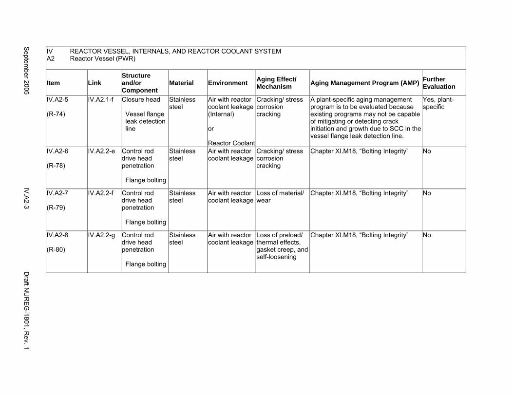
IV A2
REACTOR VESSEL, INTERNALS, AND REACTOR COOLANT SYSTEM Reactor Vessel (PWR)
Item Link Structure and/or Component
Material Environment Aging Effect/ Mechanism Aging Management Program (AMP) Further
Evaluation
IV.A2-5
(R-74)
IV.A2.1-f Closure head
Vessel flange leak detection line
Stainless steel
Air with reactor coolant leakage (Internal)
or
Reactor Coolant
Cracking/ stress corrosion cracking
A plant-specific aging management program is to be evaluated because existing programs may not be capable of mitigating or detecting crack initiation and growth due to SCC in the vessel flange leak detection line.
Yes, plant-specific
IV.A2-6
(R-78)
IV.A2.2-e Control rod drive head penetration
Flange bolting
Stainless steel
Air with reactor coolant leakage
Cracking/ stress corrosion cracking
Chapter XI.M18, “Bolting Integrity” No
IV.A2-7
(R-79)
IV.A2.2-f Control rod drive head penetration
Flange bolting
Stainless steel
Air with reactor coolant leakage
Loss of material/ wear
Chapter XI.M18, “Bolting Integrity” No
IV.A2-8
(R-80)
IV.A2.2-g Control rod drive head penetration
Flange bolting
Stainless steel
Air with reactor coolant leakage
Loss of preload/ thermal effects, gasket creep, and self-loosening
Chapter XI.M18, “Bolting Integrity” No
Septem
ber 2005 IV
.A2-3
Draft N
UR
EG
-1801, Rev. 1
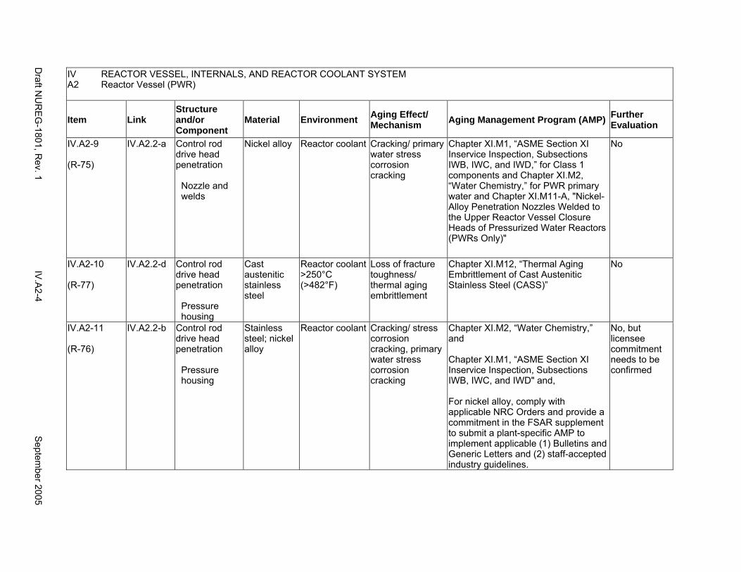
IV REACTOR VESSEL, INTERNALS, AND REACTOR COOLANT SYSTEM A2 Reactor Vessel (PWR)
Item Link Structure and/or Component
Material Environment Aging Effect/ Mechanism Aging Management Program (AMP) Further
Evaluation
IV.A2-9
(R-75)
IV.A2.2-a Control rod drive head penetration
Nozzle and welds
Nickel alloy Reactor coolant Cracking/ primary water stress corrosion cracking
Chapter XI.M1, “ASME Section XI Inservice Inspection, Subsections IWB, IWC, and IWD,” for Class 1 components and Chapter XI.M2, “Water Chemistry,” for PWR primary water and Chapter XI.M11-A, "Nickel-Alloy Penetration Nozzles Welded to the Upper Reactor Vessel Closure Heads of Pressurized Water Reactors (PWRs Only)"
No
IV.A2-10
(R-77)
IV.A2.2-d Control rod drive head penetration
Pressure housing
Cast austenitic stainless steel
Reactor coolant >250°C (>482°F)
Loss of fracture toughness/ thermal aging embrittlement
Chapter XI.M12, “Thermal Aging Embrittlement of Cast Austenitic Stainless Steel (CASS)”
No
IV.A2-11
(R-76)
IV.A2.2-b Control rod drive head penetration
Pressure housing
Stainless steel; nickel alloy
Reactor coolant Cracking/ stress corrosion cracking, primary water stress corrosion cracking
Chapter XI.M2, “Water Chemistry,” and
Chapter XI.M1, “ASME Section XI Inservice Inspection, Subsections IWB, IWC, and IWD" and,
For nickel alloy, comply with applicable NRC Orders and provide a commitment in the FSAR supplement to submit a plant-specific AMP to implement applicable (1) Bulletins and Generic Letters and (2) staff-accepted industry guidelines.
No, but licensee commitment needs to be confirmed
Draft N
UR
EG
-1801, Rev. 1
IV.A
2-4 S
eptember 2005

IV REACTOR VESSEL, INTERNALS, AND REACTOR COOLANT SYSTEM A2 Reactor Vessel (PWR)
Item Link Structure and/or Component
Material Environment Aging Effect/ Mechanism Aging Management Program (AMP) Further
Evaluation
IV.A2-12
(R-88)
IV.A2.6-a Core support pads/ core guide lugs
Nickel alloy Reactor coolant Cracking/ primary water stress corrosion cracking
Chapter XI.M2, “Water Chemistry,” and
Chapter XI.M1, “ASME Section XI Inservice Inspection, Subsections IWB, IWC, and IWD" and,
Comply with applicable NRC Orders and provide a commitment in the FSAR supplement to submit a plant-specific AMP to implement applicable (1) Bulletins and Generic Letters and (2) staff-accepted industry guidelines.
No, but licensee commitment needs to be confirmed
IV.A2-13
(R-17)
IV.A2.8-b IV.A2.5-e IV.A2.1-a
External surfaces
Steel Air with borated water leakage
Loss of material/ boric acid corrosion
Chapter XI.M10, “Boric Acid Corrosion”
No
IV.A2-14
(RP-28)
IV.A2. Flanges; nozzles; penetrations; pressure housings; safe ends; vessel shells, heads and welds
Stainless steel; steel with nickel-alloy or stainless steel cladding; nickel-alloy
Reactor Coolant Loss of material/ pitting and crevice corrosion
Chapter XI.M2, “Water Chemistry,” for PWR primary water
No
IV.A2-15
(R-83)
IV.A2.4-b Nozzle safe ends and welds:
Inlet Outlet Safety injection
Stainless steel; nickel alloy welds and/or buttering
Reactor coolant Cracking/ stress corrosion cracking, primary water stress corrosion cracking
Chapter XI.M1, “ASME Section XI Inservice Inspection, Subsections IWB, IWC, and IWD,” for Class 1 components and
Chapter XI.M2, “Water Chemistry,” for PWR primary water
No
Septem
ber 2005 IV
.A2-5
Draft N
UR
EG
-1801, Rev. 1

IV REACTOR VESSEL, INTERNALS, AND REACTOR COOLANT SYSTEM A2 Reactor Vessel (PWR)
Item Link Structure and/or Component
Material Environment Aging Effect/ Mechanism Aging Management Program (AMP) Further
Evaluation
IV.A2-16
(R-81)
IV.A2.3-a Nozzles
Inlet Outlet Safety injection
Steel with stainless steel cladding
Reactor coolant and neutron flux
Loss of fracture toughness/ neutron irradiation embrittlement
Neutron irradiation embrittlement is a time-limited aging analysis (TLAA) to be evaluated for the period of extended operation for all ferritic materials that have a neutron fluence greater than 1E17 n/cm2 (E >1 MeV) at the end of the license renewal term. The TLAA is to evaluate the impact of neutron embrittlement on: (a) the RTPTS value based on the requirements in 10 CFR 50.61, (b) the adjusted reference temperature values used for calculation of the plant’s pressure-temperature limits, and (c) the Charpy upper shelf energy or the equivalent margins analyses performed in accordance with 10 CFR Part 50, Appendix G requirements. The applicant may choose to demonstrate that the materials in the inlet, outlet, and safety injection nozzles are not controlling for the TLAA evaluations.
Yes, TLAA
IV.A2-17
(R-82)
IV.A2.3-b Nozzles
Inlet Outlet Safety injection
Steel with stainless steel cladding
Reactor coolant and neutron flux
Loss of fracture toughness/ neutron irradiation embrittlement
Chapter XI.M31, “Reactor Vessel Surveillance”
No
Draft N
UR
EG
-1801, Rev. 1
IV.A
2-6 S
eptember 2005
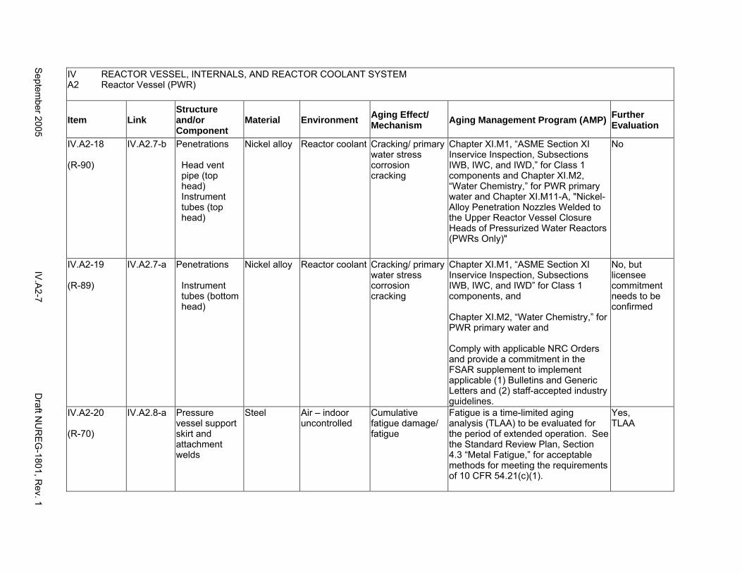
IV REACTOR VESSEL, INTERNALS, AND REACTOR COOLANT SYSTEM A2 Reactor Vessel (PWR)
Item Link Structure and/or Component
Material Environment Aging Effect/ Mechanism Aging Management Program (AMP) Further
Evaluation
IV.A2-18
(R-90)
IV.A2.7-b Penetrations
Head vent pipe (top head) Instrument tubes (top head)
Nickel alloy Reactor coolant Cracking/ primary water stress corrosion cracking
Chapter XI.M1, “ASME Section XI Inservice Inspection, Subsections IWB, IWC, and IWD,” for Class 1 components and Chapter XI.M2, “Water Chemistry,” for PWR primary water and Chapter XI.M11-A, "Nickel-Alloy Penetration Nozzles Welded to the Upper Reactor Vessel Closure Heads of Pressurized Water Reactors (PWRs Only)"
No
IV.A2-19
(R-89)
IV.A2.7-a Penetrations
Instrument tubes (bottom head)
Nickel alloy Reactor coolant Cracking/ primary water stress corrosion cracking
Chapter XI.M1, “ASME Section XI Inservice Inspection, Subsections IWB, IWC, and IWD” for Class 1 components, and
Chapter XI.M2, “Water Chemistry,” for PWR primary water and
Comply with applicable NRC Orders and provide a commitment in the FSAR supplement to implement applicable (1) Bulletins and Generic Letters and (2) staff-accepted industry guidelines.
No, but licensee commitment needs to be confirmed
IV.A2-20
(R-70)
IV.A2.8-a Pressure vessel support skirt and attachment welds
Steel Air – indoor uncontrolled
Cumulative fatigue damage/ fatigue
Fatigue is a time-limited aging analysis (TLAA) to be evaluated for the period of extended operation. See the Standard Review Plan, Section 4.3 “Metal Fatigue,” for acceptable methods for meeting the requirements of 10 CFR 54.21(c)(1).
Yes, TLAA
Septem
ber 2005 IV
.A2-7
Draft N
UR
EG
-1801, Rev. 1
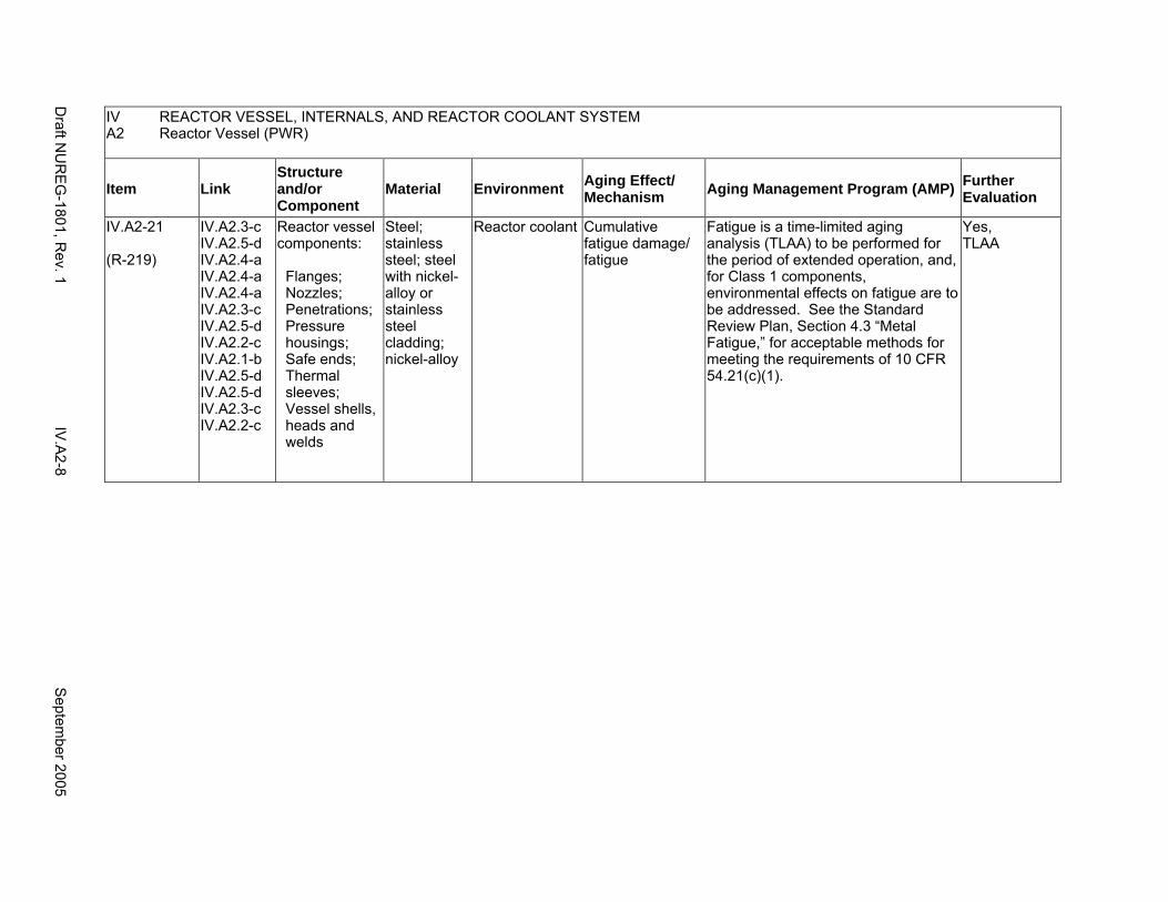
IV REACTOR VESSEL, INTERNALS, AND REACTOR COOLANT SYSTEM A2 Reactor Vessel (PWR)
Item Link Structure and/or Component
Material Environment Aging Effect/ Mechanism Aging Management Program (AMP) Further
Evaluation
IV.A2-21
(R-219)
IV.A2.3-c IV.A2.5-d IV.A2.4-a IV.A2.4-a IV.A2.4-a IV.A2.3-c IV.A2.5-d IV.A2.2-c IV.A2.1-b IV.A2.5-d IV.A2.5-d IV.A2.3-c IV.A2.2-c
Reactor vessel components:
Flanges; Nozzles; Penetrations; Pressure housings; Safe ends; Thermal sleeves; Vessel shells, heads and welds
Steel; stainless steel; steel with nickel-alloy or stainless steel cladding; nickel-alloy
Reactor coolant Cumulative fatigue damage/ fatigue
Fatigue is a time-limited aging analysis (TLAA) to be performed for the period of extended operation, and, for Class 1 components, environmental effects on fatigue are to be addressed. See the Standard Review Plan, Section 4.3 “Metal Fatigue,” for acceptable methods for meeting the requirements of 10 CFR 54.21(c)(1).
Yes, TLAA
Draft N
UR
EG
-1801, Rev. 1
IV.A
2-8 S
eptember 2005
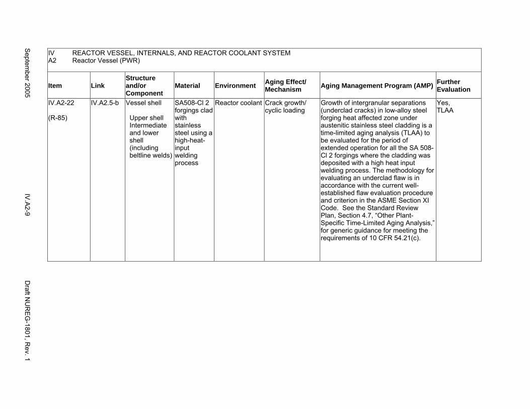
IV REACTOR VESSEL, INTERNALS, AND REACTOR COOLANT SYSTEM A2 Reactor Vessel (PWR)
Item Link Structure and/or Component
Material Environment Aging Effect/ Mechanism Aging Management Program (AMP) Further
Evaluation
IV.A2-22
(R-85)
IV.A2.5-b Vessel shell
Upper shell Intermediate and lower shell (including beltline welds)
SA508-Cl 2 forgings clad with stainless steel using a high-heatinput welding process
Reactor coolant Crack growth/ cyclic loading
Growth of intergranular separations (underclad cracks) in low-alloy steel forging heat affected zone under austenitic stainless steel cladding is a time-limited aging analysis (TLAA) to be evaluated for the period of extended operation for all the SA 508Cl 2 forgings where the cladding was deposited with a high heat input welding process. The methodology for evaluating an underclad flaw is in accordance with the current well-established flaw evaluation procedure and criterion in the ASME Section XI Code. See the Standard Review Plan, Section 4.7, “Other Plant-Specific Time-Limited Aging Analysis,” for generic guidance for meeting the requirements of 10 CFR 54.21(c).
Yes, TLAA
Septem
ber 2005 IV
.A2-9
Draft N
UR
EG
-1801, Rev. 1
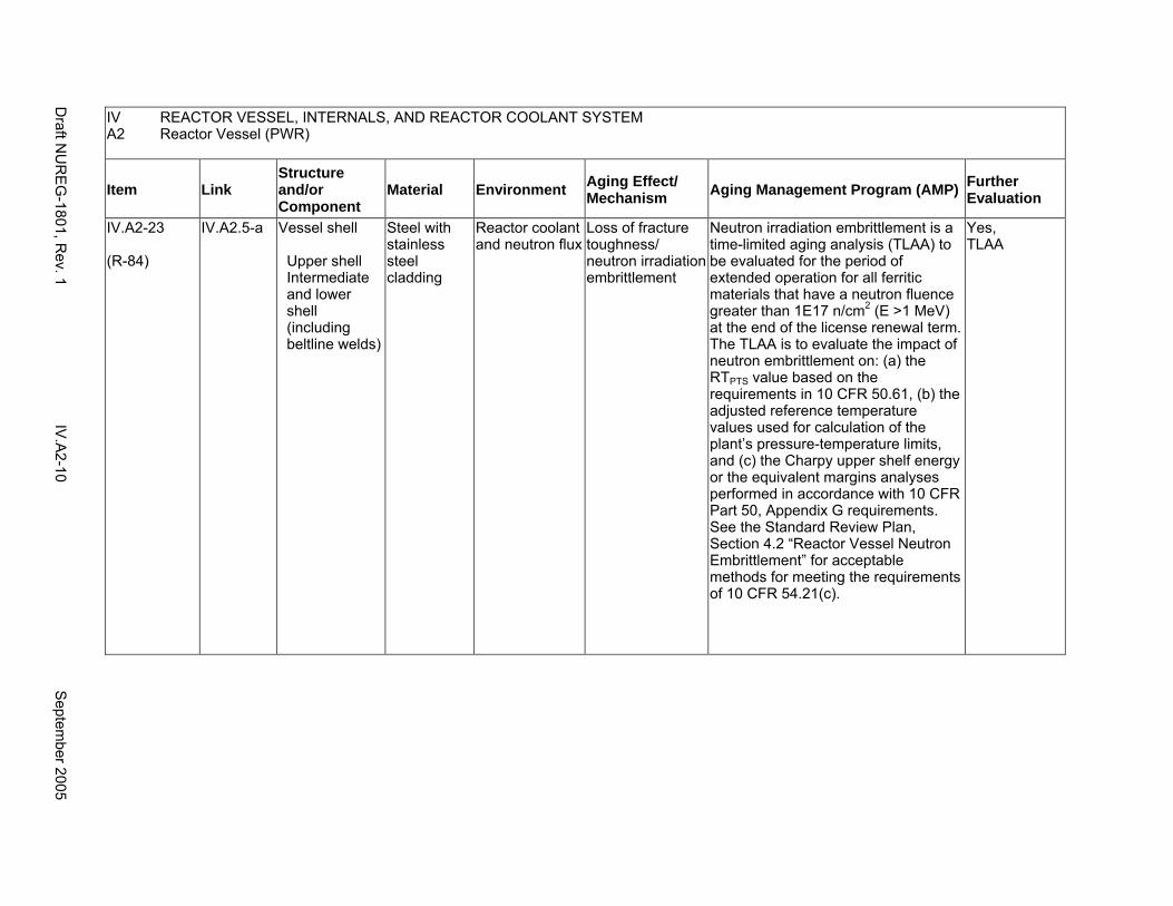
IV REACTOR VESSEL, INTERNALS, AND REACTOR COOLANT SYSTEM A2 Reactor Vessel (PWR)
Item Link Structure and/or Component
Material Environment Aging Effect/ Mechanism Aging Management Program (AMP) Further
Evaluation
IV.A2-23
(R-84)
IV.A2.5-a Vessel shell
Upper shell Intermediate and lower shell (including beltline welds)
Steel with stainless steel cladding
Reactor coolant and neutron flux
Loss of fracture toughness/ neutron irradiation embrittlement
Neutron irradiation embrittlement is a time-limited aging analysis (TLAA) to be evaluated for the period of extended operation for all ferritic materials that have a neutron fluence greater than 1E17 n/cm2 (E >1 MeV) at the end of the license renewal term. The TLAA is to evaluate the impact of neutron embrittlement on: (a) the RTPTS value based on the requirements in 10 CFR 50.61, (b) the adjusted reference temperature values used for calculation of the plant’s pressure-temperature limits, and (c) the Charpy upper shelf energy or the equivalent margins analyses performed in accordance with 10 CFR Part 50, Appendix G requirements. See the Standard Review Plan, Section 4.2 “Reactor Vessel Neutron Embrittlement” for acceptable methods for meeting the requirements of 10 CFR 54.21(c).
Yes, TLAA
Draft N
UR
EG
-1801, Rev. 1
IV.A
2-10 S
eptember 2005
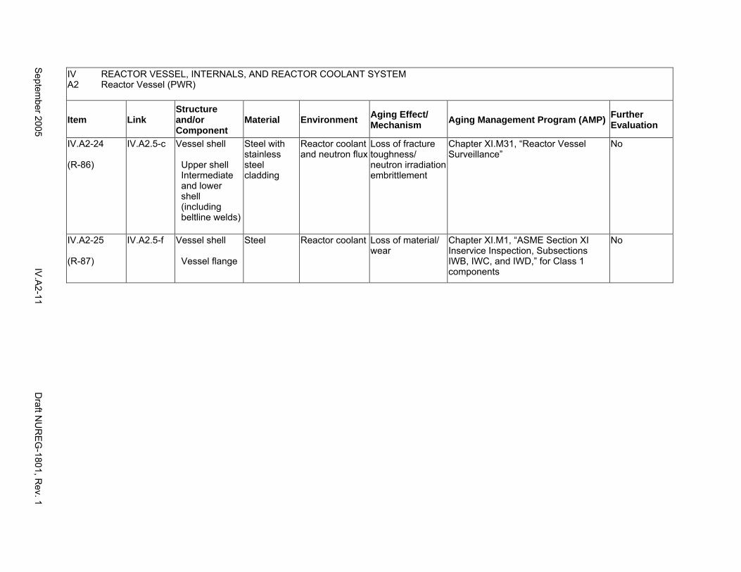
IV REACTOR VESSEL, INTERNALS, AND REACTOR COOLANT SYSTEM A2 Reactor Vessel (PWR)
Item Link Structure and/or Component
Material Environment Aging Effect/ Mechanism Aging Management Program (AMP) Further
Evaluation
IV.A2-24
(R-86)
IV.A2.5-c Vessel shell
Upper shell Intermediate and lower shell (including beltline welds)
Steel with stainless steel cladding
Reactor coolant and neutron flux
Loss of fracture toughness/ neutron irradiation embrittlement
Chapter XI.M31, “Reactor Vessel Surveillance”
No
IV.A2-25
(R-87)
IV.A2.5-f Vessel shell
Vessel flange
Steel Reactor coolant Loss of material/ wear
Chapter XI.M1, “ASME Section XI Inservice Inspection, Subsections IWB, IWC, and IWD,” for Class 1 components
No
Septem
ber 2005 IV
.A2-11
Draft N
UR
EG
-1801, Rev. 1

This Page Intentionally Left Blank
Draft NUREG-1801, Rev. 1 IV A2-12 September 2005
B1. REACTOR VESSEL INTERNALS (BOILING WATER REACTOR)
Systems, Structures, and Components
This section addresses the boiling water reactor (BWR) vessel internals and consists of the core shroud (including repairs) and core plate, the top guide, feedwater spargers, core spray lines and spargers, jet pump assemblies, fuel supports and control rod drive (CRD), and instrument housings, such as the intermediate range monitor (IRM) dry tubes, the low power range monitor (LPRM) dry tubes, and the source range monitor (SRM) dry tubes. Based on Regulatory Guide 1.26, “Quality Group Classifications and Standards for Water-, Steam-, and Radioactive-Waste-Containing Components of Nuclear Power Plants,” all structures and components that comprise the reactor vessel are governed by Group A or B Quality Standards.
Common miscellaneous material/environment combinations where aging effects are not expected to degrade the ability of the structure or component to perform its intended function for the extended period of operation are included in IV.E.
System Interfaces
The systems that interface with the reactor vessel internals include the reactor pressure vessel (IV.A1) and the reactor coolant pressure boundary (IV.C1).
September 2005 IV B1-1 Draft NUREG-1801, Rev. 1
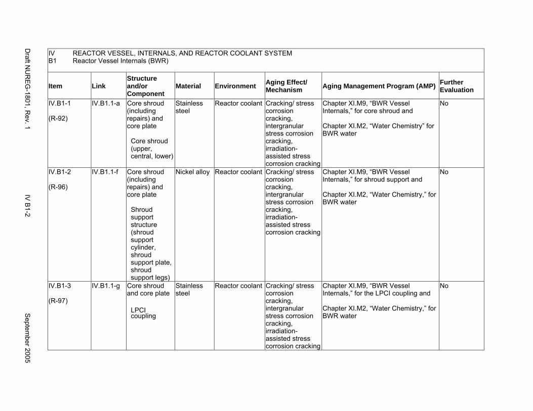
IV B1
REACTOR VESSEL, INTERNALS, AND REACTOR COOLANT SYSTEM Reactor Vessel Internals (BWR)
Item Link Structure and/or Component
Material Environment Aging Effect/ Mechanism Aging Management Program (AMP) Further
Evaluation
IV.B1-1
(R-92)
IV.B1.1-a Core shroud (including repairs) and core plate
Core shroud (upper, central, lower)
Stainless steel
Reactor coolant Cracking/ stress corrosion cracking, intergranular stress corrosion cracking, irradiation-assisted stress corrosion cracking
Chapter XI.M9, “BWR Vessel Internals,” for core shroud and
Chapter XI.M2, “Water Chemistry” for BWR water
No
IV.B1-2
(R-96)
IV.B1.1-f Core shroud (including repairs) and core plate
Shroud support structure (shroud support cylinder, shroud support plate, shroud support legs)
Nickel alloy Reactor coolant Cracking/ stress corrosion cracking, intergranular stress corrosion cracking, irradiation-assisted stress corrosion cracking
Chapter XI.M9, “BWR Vessel Internals,” for shroud support and
Chapter XI.M2, “Water Chemistry,” for BWR water
No
IV.B1-3
(R-97)
IV.B1.1-g Core shroud and core plate
LPCI coupling
Stainless steel
Reactor coolant Cracking/ stress corrosion cracking, intergranular stress corrosion cracking, irradiation-assisted stress corrosion cracking
Chapter XI.M9, “BWR Vessel Internals,” for the LPCI coupling and
Chapter XI.M2, “Water Chemistry,” for BWR water
No
Draft N
UR
EG
-1801, Rev. 1
IV B
1-2 S
eptember 2005
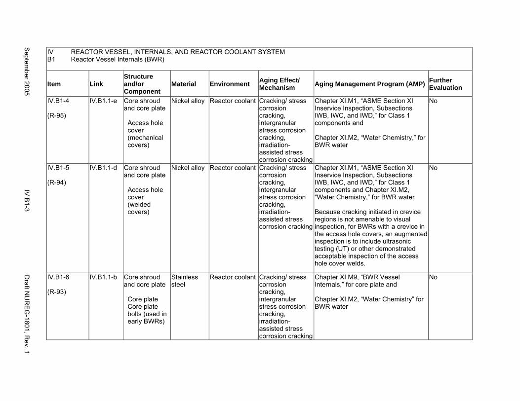
IV B1
REACTOR VESSEL, INTERNALS, AND REACTOR COOLANT SYSTEM Reactor Vessel Internals (BWR)
Item Link Structure and/or Component
Material Environment Aging Effect/ Mechanism Aging Management Program (AMP) Further
Evaluation
IV.B1-4
(R-95)
IV.B1.1-e Core shroud and core plate
Access hole cover (mechanical covers)
Nickel alloy Reactor coolant Cracking/ stress corrosion cracking, intergranular stress corrosion cracking, irradiation-assisted stress corrosion cracking
Chapter XI.M1, “ASME Section XI Inservice Inspection, Subsections IWB, IWC, and IWD,” for Class 1 components and
Chapter XI.M2, “Water Chemistry,” for BWR water
No
IV.B1-5
(R-94)
IV.B1.1-d Core shroud and core plate
Access hole cover (welded covers)
Nickel alloy Reactor coolant Cracking/ stress corrosion cracking, intergranular stress corrosion cracking, irradiation-assisted stress corrosion cracking
Chapter XI.M1, “ASME Section XI Inservice Inspection, Subsections IWB, IWC, and IWD,” for Class 1 components and Chapter XI.M2, “Water Chemistry,” for BWR water
Because cracking initiated in crevice regions is not amenable to visual inspection, for BWRs with a crevice in the access hole covers, an augmented inspection is to include ultrasonic testing (UT) or other demonstrated acceptable inspection of the access hole cover welds.
No
IV.B1-6
(R-93)
IV.B1.1-b Core shroud and core plate
Core plate Core plate bolts (used in early BWRs)
Stainless steel
Reactor coolant Cracking/ stress corrosion cracking, intergranular stress corrosion cracking, irradiation-assisted stress corrosion cracking
Chapter XI.M9, “BWR Vessel Internals,” for core plate and
Chapter XI.M2, “Water Chemistry” for BWR water
No
Septem
ber 2005 IV
B1-3
Draft N
UR
EG
-1801, Rev. 1
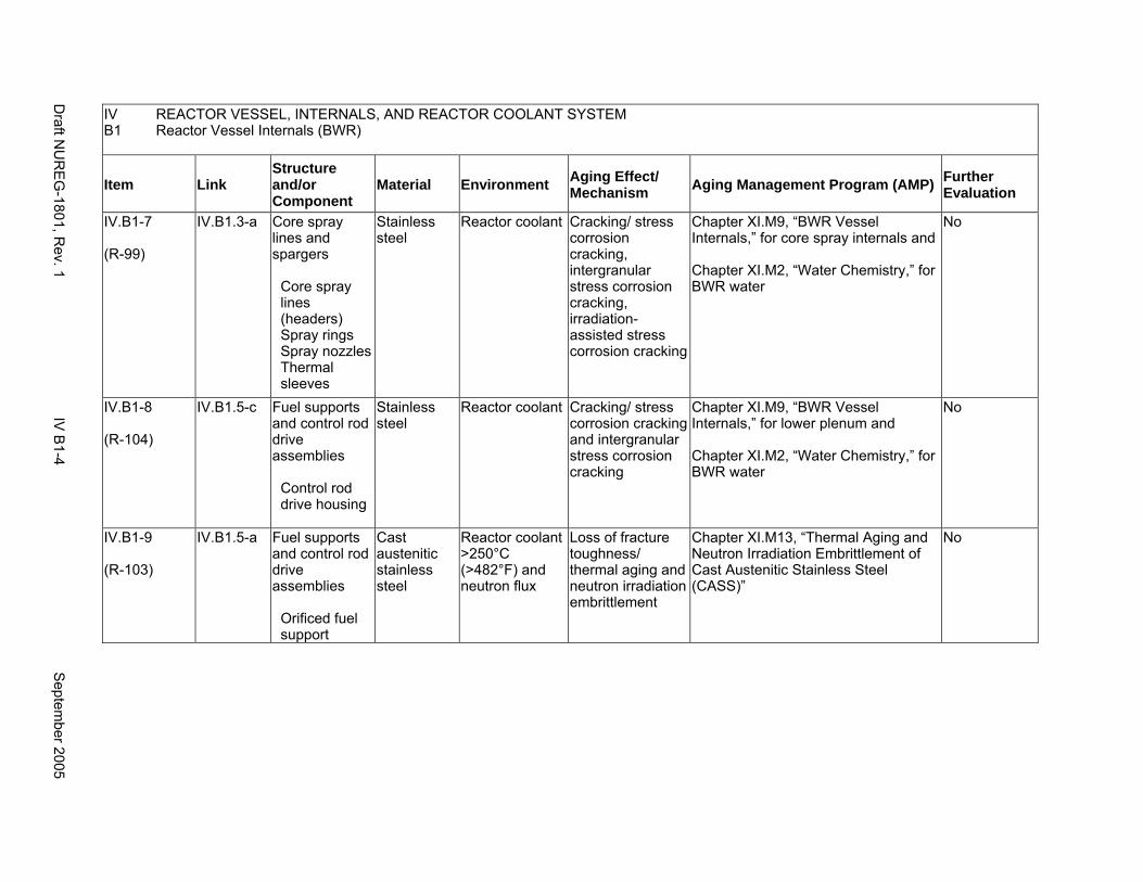
IV B1
REACTOR VESSEL, INTERNALS, AND REACTOR COOLANT SYSTEM Reactor Vessel Internals (BWR)
Item Link Structure and/or Component
Material Environment Aging Effect/ Mechanism Aging Management Program (AMP) Further
Evaluation
IV.B1-7
(R-99)
IV.B1.3-a Core spray lines and spargers
Core spray lines (headers) Spray rings Spray nozzles Thermal sleeves
Stainless steel
Reactor coolant Cracking/ stress corrosion cracking, intergranular stress corrosion cracking, irradiation-assisted stress corrosion cracking
Chapter XI.M9, “BWR Vessel Internals,” for core spray internals and
Chapter XI.M2, “Water Chemistry,” for BWR water
No
IV.B1-8
(R-104)
IV.B1.5-c Fuel supports and control rod drive assemblies
Control rod drive housing
Stainless steel
Reactor coolant Cracking/ stress corrosion cracking and intergranular stress corrosion cracking
Chapter XI.M9, “BWR Vessel Internals,” for lower plenum and
Chapter XI.M2, “Water Chemistry,” for BWR water
No
IV.B1-9
(R-103)
IV.B1.5-a Fuel supports and control rod drive assemblies
Orificed fuel support
Cast austenitic stainless steel
Reactor coolant >250°C (>482°F) and neutron flux
Loss of fracture toughness/ thermal aging and neutron irradiation embrittlement
Chapter XI.M13, “Thermal Aging and Neutron Irradiation Embrittlement of Cast Austenitic Stainless Steel (CASS)”
No
Draft N
UR
EG
-1801, Rev. 1
IV B
1-4 S
eptember 2005
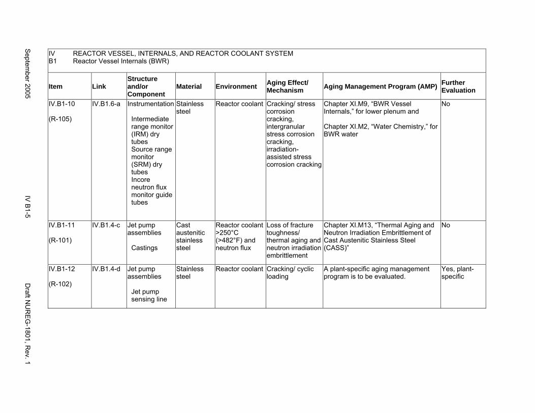
IV REACTOR VESSEL, INTERNALS, AND REACTOR COOLANT SYSTEM B1 Reactor Vessel Internals (BWR)
Item Link Structure and/or Component
Material Environment Aging Effect/ Mechanism Aging Management Program (AMP) Further
Evaluation
IV.B1-10
(R-105)
IV.B1.6-a Instrumentation
Intermediate range monitor (IRM) dry tubes Source range monitor (SRM) dry tubes Incore neutron flux monitor guide tubes
Stainless steel
Reactor coolant Cracking/ stress corrosion cracking, intergranular stress corrosion cracking, irradiation-assisted stress corrosion cracking
Chapter XI.M9, “BWR Vessel Internals,” for lower plenum and
Chapter XI.M2, “Water Chemistry,” for BWR water
No
IV.B1-11
(R-101)
IV.B1.4-c Jet pump assemblies
Castings
Cast austenitic stainless steel
Reactor coolant >250°C (>482°F) and neutron flux
Loss of fracture toughness/ thermal aging and neutron irradiation embrittlement
Chapter XI.M13, “Thermal Aging and Neutron Irradiation Embrittlement of Cast Austenitic Stainless Steel (CASS)”
No
IV.B1-12
(R-102)
IV.B1.4-d Jet pump assemblies
Jet pump sensing line
Stainless steel
Reactor coolant Cracking/ cyclic loading
A plant-specific aging management program is to be evaluated.
Yes, plant-specific
Septem
ber 2005 IV
B1-5
Draft N
UR
EG
-1801, Rev. 1
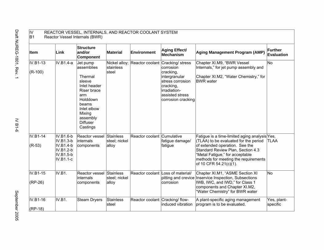
IV REACTOR VESSEL, INTERNALS, AND REACTOR COOLANT SYSTEM B1 Reactor Vessel Internals (BWR)
Item Link Structure and/or Component
Material Environment Aging Effect/ Mechanism Aging Management Program (AMP) Further
Evaluation
IV.B1-13
(R-100)
IV.B1.4-a Jet pump assemblies
Thermal sleeve Inlet header Riser brace arm Holddown beams Inlet elbow Mixing assembly Diffuser Castings
Nickel alloy; stainless steel
Reactor coolant Cracking/ stress corrosion cracking, intergranular stress corrosion cracking, irradiation-assisted stress corrosion cracking
Chapter XI.M9, “BWR Vessel Internals,” for jet pump assembly and
Chapter XI.M2, “Water Chemistry,” for BWR water
No
IV.B1-14
(R-53)
IV.B1.6-b IV.B1.3-b IV.B1.4-b IV.B1.2-b IV.B1.5-b IV.B1.1-c
Reactor vessel internals components
Stainless steel; nickel alloy
Reactor coolant Cumulative fatigue damage/ fatigue
Fatigue is a time-limited aging analysis (TLAA) to be evaluated for the period of extended operation. See the Standard Review Plan, Section 4.3 “Metal Fatigue,” for acceptable methods for meeting the requirements of 10 CFR 54.21(c)(1).
Yes, TLAA
IV.B1-15
(RP-26)
IV.B1. Reactor vessel internals components
Stainless steel; nickel alloy
Reactor coolant Loss of material/ pitting and crevice corrosion
Chapter XI.M1, “ASME Section XI Inservice Inspection, Subsections IWB, IWC, and IWD,” for Class 1 components and Chapter XI.M2, “Water Chemistry” for BWR water
No
IV.B1-16
(RP-18)
IV.B1. Steam Dryers Stainless steel
Reactor coolant Cracking/ flow-induced vibration
A plant-specific aging management program is to be evaluated.
Yes, plant-specific
Draft N
UR
EG
-1801, Rev. 1
IV B
1-6 S
eptember 2005
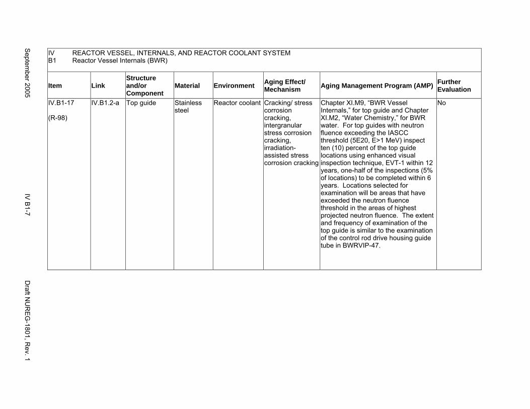
IV REACTOR VESSEL, INTERNALS, AND REACTOR COOLANT SYSTEM B1 Reactor Vessel Internals (BWR)
Item Link Structure and/or Component
Material Environment Aging Effect/ Mechanism Aging Management Program (AMP) Further
Evaluation
IV.B1-17
(R-98)
IV.B1.2-a Top guide Stainless steel
Reactor coolant Cracking/ stress corrosion cracking, intergranular stress corrosion cracking, irradiation-assisted stress corrosion cracking
Chapter XI.M9, “BWR Vessel Internals,” for top guide and Chapter XI.M2, “Water Chemistry,” for BWR water. For top guides with neutron fluence exceeding the IASCC threshold (5E20, E>1 MeV) inspect ten (10) percent of the top guide locations using enhanced visual inspection technique, EVT-1 within 12 years, one-half of the inspections (5% of locations) to be completed within 6 years. Locations selected for examination will be areas that have exceeded the neutron fluence threshold in the areas of highest projected neutron fluence. The extent and frequency of examination of the top guide is similar to the examination of the control rod drive housing guide tube in BWRVIP-47.
No
Septem
ber 2005 IV
B1-7
Draft N
UR
EG
-1801, Rev. 1

This Page Intentionally Left Blank
Draft NUREG-1801, Rev. 1 IV B1-8 September 2005
B2. REACTOR VESSEL INTERNALS (PWR) - WESTINGHOUSE
Systems, Structures, and Components
This section addresses the Westinghouse pressurized water reactor (PWR) vessel internals and consists of the upper internals assembly, the rod control cluster assemblies (RCCA) guide tube assemblies, the core barrel, the baffle/former assembly, the lower internal assembly, and the instrumentation support structures. Based on Regulatory Guide 1.26, “Quality Group Classifications and Standards for Water-, Steam-, and Radioactive-Waste-Containing Components of Nuclear Power Plants,” all structures and components that comprise the reactor vessel are governed by Group A or B Quality Standards.
Common miscellaneous material/environment combinations where aging effects are not expected to degrade the ability of the structure or component to perform its intended function for the extended period of operation are included in IV.E.
System Interfaces
The systems that interface with the reactor vessel internals include the reactor pressure vessel (IV.A2).
September 2005 IV B2-1 Draft NUREG-1801, Rev. 1

IV REACTOR VESSEL, INTERNALS, AND REACTOR COOLANT SYSTEM B2 Reactor Vessel Internals (PWR) - Westinghouse
Item Link Structure and/or Component
Material Environment Aging Effect/ Mechanism Aging Management Program (AMP) Further
Evaluation
IV.B2-1
(R-124)
IV.B2.4-b Baffle/former assembly
Baffle and former plates
Stainless steel
Reactor coolant Changes in dimensions/ void swelling
No further aging management review is necessary if the applicant provides a commitment in the FSAR supplement to (1) participate in the industry programs for investigating and managing aging effects on reactor internals; (2) evaluate and implement the results of the industry programs as applicable to the reactor internals; and (3) upon completion of these programs, but not less than 24 months before entering the period of extended operation, submit an inspection plan for reactor internals to the NRC for review and approval.
No, but licensee commitment needs to be confirmed
Draft N
UR
EG
-1801, Rev. 1
IV B
2-2 S
eptember 2005
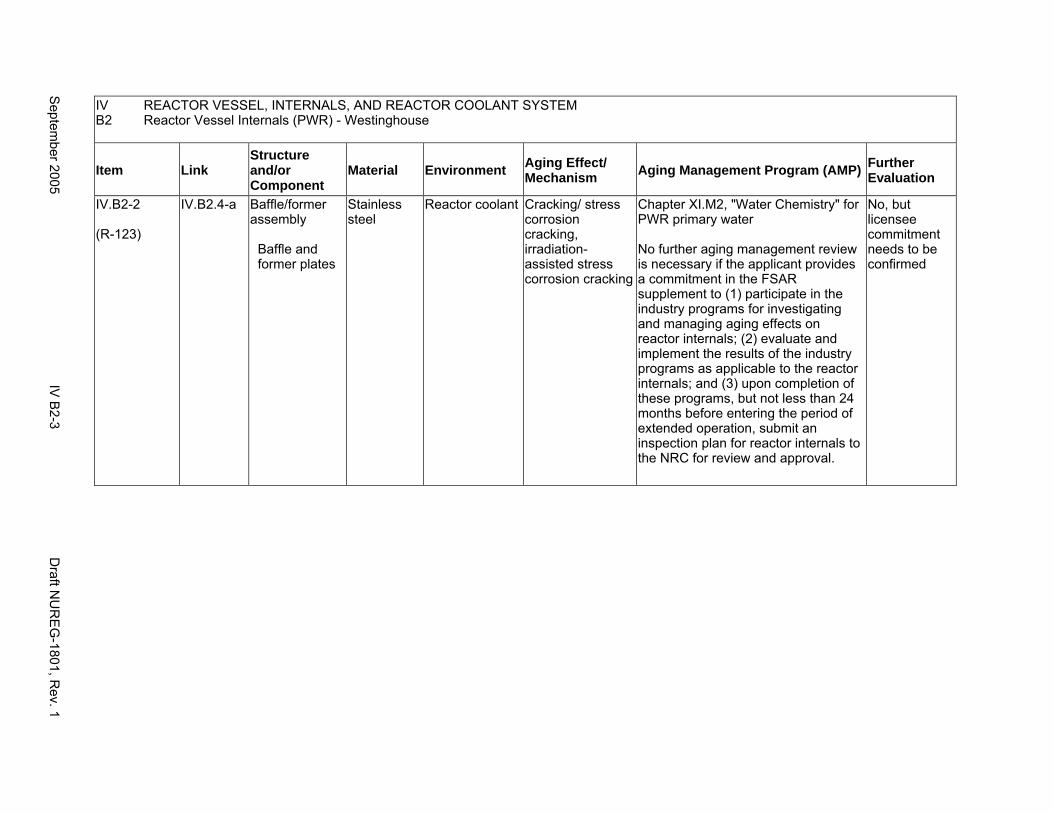
IV B2
REACTOR VESSEL, INTERNALS, AND REACTOR COOLANT SYSTEM Reactor Vessel Internals (PWR) - Westinghouse
Item Link Structure and/or Component
Material Environment Aging Effect/ Mechanism Aging Management Program (AMP) Further
Evaluation
IV.B2-2
(R-123)
IV.B2.4-a Baffle/former assembly
Baffle and former plates
Stainless steel
Reactor coolant Cracking/ stress corrosion cracking, irradiation-assisted stress corrosion cracking
Chapter XI.M2, "Water Chemistry" for PWR primary water
No further aging management review is necessary if the applicant provides a commitment in the FSAR supplement to (1) participate in the industry programs for investigating and managing aging effects on reactor internals; (2) evaluate and implement the results of the industry programs as applicable to the reactor internals; and (3) upon completion of these programs, but not less than 24 months before entering the period of extended operation, submit an inspection plan for reactor internals to the NRC for review and approval.
No, but licensee commitment needs to be confirmed
Septem
ber 2005 IV
B2-3
Draft N
UR
EG
-1801, Rev. 1
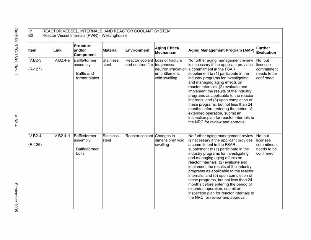
IV B2
REACTOR VESSEL, INTERNALS, AND REACTOR COOLANT SYSTEM Reactor Vessel Internals (PWR) - Westinghouse
Item Link Structure and/or Component
Material Environment Aging Effect/ Mechanism Aging Management Program (AMP) Further
Evaluation
IV.B2-3
(R-127)
IV.B2.4-e Baffle/former assembly
Baffle and former plates
Stainless steel
Reactor coolant and neutron flux
Loss of fracture toughness/ neutron irradiation embrittlement, void swelling
No further aging management review is necessary if the applicant provides a commitment in the FSAR supplement to (1) participate in the industry programs for investigating and managing aging effects on reactor internals; (2) evaluate and implement the results of the industry programs as applicable to the reactor internals; and (3) upon completion of these programs, but not less than 24 months before entering the period of extended operation, submit an inspection plan for reactor internals to the NRC for review and approval.
No, but licensee commitment needs to be confirmed
IV.B2-4
(R-126)
IV.B2.4-d Baffle/former assembly
Baffle/former bolts
Stainless steel
Reactor coolant Changes in dimensions/ void swelling
No further aging management review is necessary if the applicant provides a commitment in the FSAR supplement to (1) participate in the industry programs for investigating and managing aging effects on reactor internals; (2) evaluate and implement the results of the industry programs as applicable to the reactor internals; and (3) upon completion of these programs, but not less than 24 months before entering the period of extended operation, submit an inspection plan for reactor internals to the NRC for review and approval.
No, but licensee commitment needs to be confirmed
Draft N
UR
EG
-1801, Rev. 1
IV B
2-4 S
eptember 2005
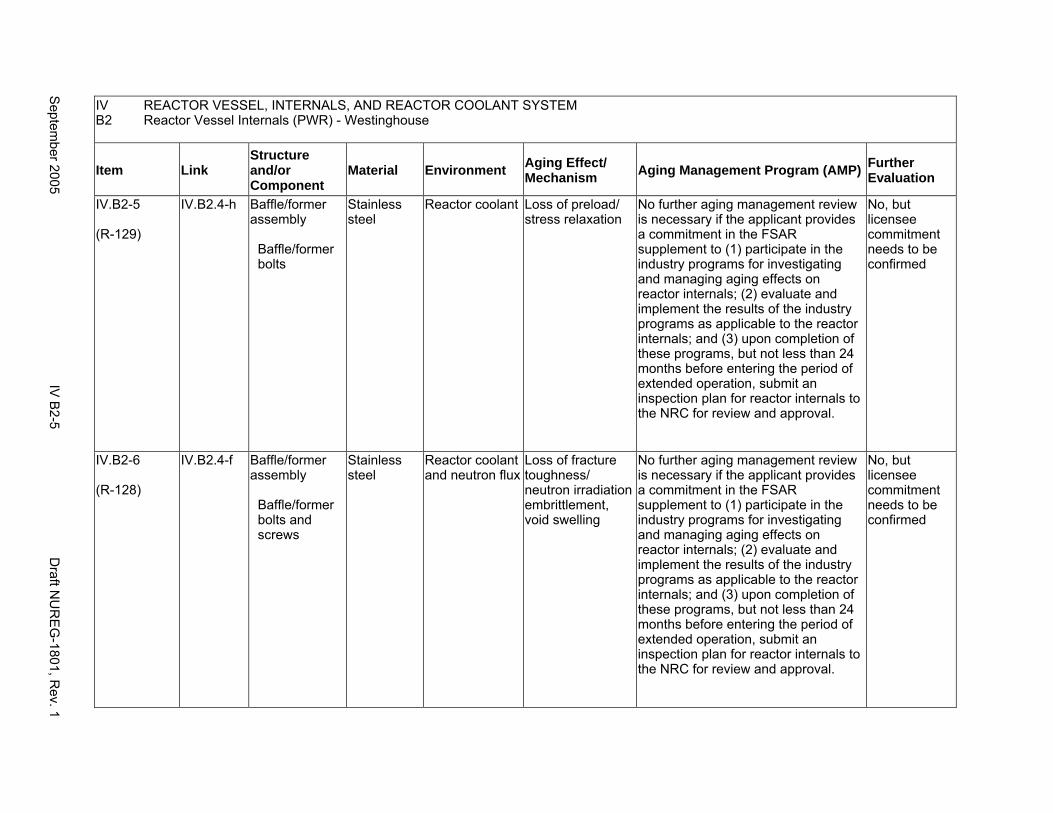
IV B2
REACTOR VESSEL, INTERNALS, AND REACTOR COOLANT SYSTEM Reactor Vessel Internals (PWR) - Westinghouse
Item Link Structure and/or Component
Material Environment Aging Effect/ Mechanism Aging Management Program (AMP) Further
Evaluation
IV.B2-5
(R-129)
IV.B2.4-h Baffle/former assembly
Baffle/former bolts
Stainless steel
Reactor coolant Loss of preload/ stress relaxation
No further aging management review is necessary if the applicant provides a commitment in the FSAR supplement to (1) participate in the industry programs for investigating and managing aging effects on reactor internals; (2) evaluate and implement the results of the industry programs as applicable to the reactor internals; and (3) upon completion of these programs, but not less than 24 months before entering the period of extended operation, submit an inspection plan for reactor internals to the NRC for review and approval.
No, but licensee commitment needs to be confirmed
IV.B2-6
(R-128)
IV.B2.4-f Baffle/former assembly
Baffle/former bolts and screws
Stainless steel
Reactor coolant and neutron flux
Loss of fracture toughness/ neutron irradiation embrittlement, void swelling
No further aging management review is necessary if the applicant provides a commitment in the FSAR supplement to (1) participate in the industry programs for investigating and managing aging effects on reactor internals; (2) evaluate and implement the results of the industry programs as applicable to the reactor internals; and (3) upon completion of these programs, but not less than 24 months before entering the period of extended operation, submit an inspection plan for reactor internals to the NRC for review and approval.
No, but licensee commitment needs to be confirmed
Septem
ber 2005 IV
B2-5
Draft N
UR
EG
-1801, Rev. 1
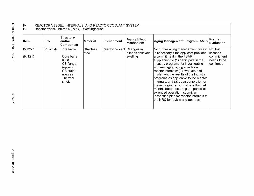
IV REACTOR VESSEL, INTERNALS, AND REACTOR COOLANT SYSTEM B2 Reactor Vessel Internals (PWR) - Westinghouse
Item Link Structure and/or Component
Material Environment Aging Effect/ Mechanism Aging Management Program (AMP) Further
Evaluation
IV.B2-7
(R-121)
IV.B2.3-b Core barrel
Core barrel (CB) CB flange (upper) CB outlet nozzles Thermal shield
Stainless steel
Reactor coolant Changes in dimensions/ void swelling
No further aging management review is necessary if the applicant provides a commitment in the FSAR supplement to (1) participate in the industry programs for investigating and managing aging effects on reactor internals; (2) evaluate and implement the results of the industry programs as applicable to the reactor internals; and (3) upon completion of these programs, but not less than 24 months before entering the period of extended operation, submit an inspection plan for reactor internals to the NRC for review and approval.
No, but licensee commitment needs to be confirmed
Draft N
UR
EG
-1801, Rev. 1
IV B
2-6 S
eptember 2005

IV B2
REACTOR VESSEL, INTERNALS, AND REACTOR COOLANT SYSTEM Reactor Vessel Internals (PWR) - Westinghouse
Item Link Structure and/or Component
Material Environment Aging Effect/ Mechanism Aging Management Program (AMP) Further
Evaluation
IV.B2-8
(R-120)
IV.B2.3-a Core barrel
Core barrel (CB) CB flange (upper) CB outlet nozzles Thermal shield
Stainless steel
Reactor coolant Cracking/ stress corrosion cracking, irradiation-assisted stress corrosion cracking
Chapter XI.M2, "Water Chemistry" for PWR primary water
No further aging management review is necessary if the applicant provides a commitment in the FSAR supplement to (1) participate in the industry programs for investigating and managing aging effects on reactor internals; (2) evaluate and implement the results of the industry programs as applicable to the reactor internals; and (3) upon completion of these programs, but not less than 24 months before entering the period of extended operation, submit an inspection plan for reactor internals to the NRC for review and approval.
No, but licensee commitment needs to be confirmed
Septem
ber 2005 IV
B2-7
Draft N
UR
EG
-1801, Rev. 1
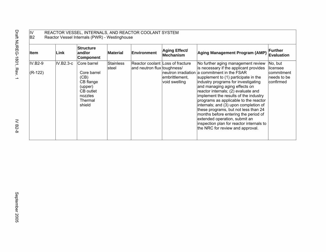
IV REACTOR VESSEL, INTERNALS, AND REACTOR COOLANT SYSTEM B2 Reactor Vessel Internals (PWR) - Westinghouse
Item Link Structure and/or Component
Material Environment Aging Effect/ Mechanism Aging Management Program (AMP) Further
Evaluation
IV.B2-9
(R-122)
IV.B2.3-c Core barrel
Core barrel (CB) CB flange (upper) CB outlet nozzles Thermal shield
Stainless steel
Reactor coolant and neutron flux
Loss of fracture toughness/ neutron irradiation embrittlement, void swelling
No further aging management review is necessary if the applicant provides a commitment in the FSAR supplement to (1) participate in the industry programs for investigating and managing aging effects on reactor internals; (2) evaluate and implement the results of the industry programs as applicable to the reactor internals; and (3) upon completion of these programs, but not less than 24 months before entering the period of extended operation, submit an inspection plan for reactor internals to the NRC for review and approval.
No, but licensee commitment needs to be confirmed
Draft N
UR
EG
-1801, Rev. 1
IV B
2-8 S
eptember 2005
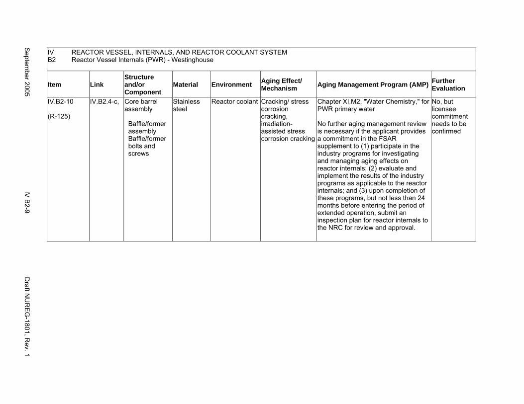
IV REACTOR VESSEL, INTERNALS, AND REACTOR COOLANT SYSTEM B2 Reactor Vessel Internals (PWR) - Westinghouse
Item Link Structure and/or Component
Material Environment Aging Effect/ Mechanism Aging Management Program (AMP) Further
Evaluation
IV.B2-10
(R-125)
IV.B2.4-c, Core barrel assembly
Baffle/former assembly Baffle/former bolts and screws
Stainless steel
Reactor coolant Cracking/ stress corrosion cracking, irradiation-assisted stress corrosion cracking
Chapter XI.M2, "Water Chemistry," for PWR primary water
No further aging management review is necessary if the applicant provides a commitment in the FSAR supplement to (1) participate in the industry programs for investigating and managing aging effects on reactor internals; (2) evaluate and implement the results of the industry programs as applicable to the reactor internals; and (3) upon completion of these programs, but not less than 24 months before entering the period of extended operation, submit an inspection plan for reactor internals to the NRC for review and approval.
No, but licensee commitment needs to be confirmed
Septem
ber 2005 IV
B2-9
Draft N
UR
EG
-1801, Rev. 1
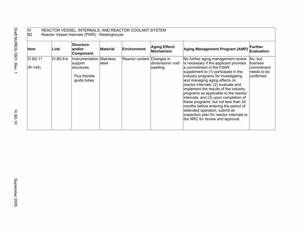
IV REACTOR VESSEL, INTERNALS, AND REACTOR COOLANT SYSTEM B2 Reactor Vessel Internals (PWR) - Westinghouse
Item Link Structure and/or Component
Material Environment Aging Effect/ Mechanism Aging Management Program (AMP) Further
Evaluation
IV.B2-11
(R-144)
IV.B2.6-b Instrumentation support structures
Flux thimble guide tubes
Stainless steel
Reactor coolant Changes in dimensions/ void swelling
No further aging management review is necessary if the applicant provides a commitment in the FSAR supplement to (1) participate in the industry programs for investigating and managing aging effects on reactor internals; (2) evaluate and implement the results of the industry programs as applicable to the reactor internals; and (3) upon completion of these programs, but not less than 24 months before entering the period of extended operation, submit an inspection plan for reactor internals to the NRC for review and approval.
No, but licensee commitment needs to be confirmed
Draft N
UR
EG
-1801, Rev. 1
IV B
2-10 S
eptember 2005
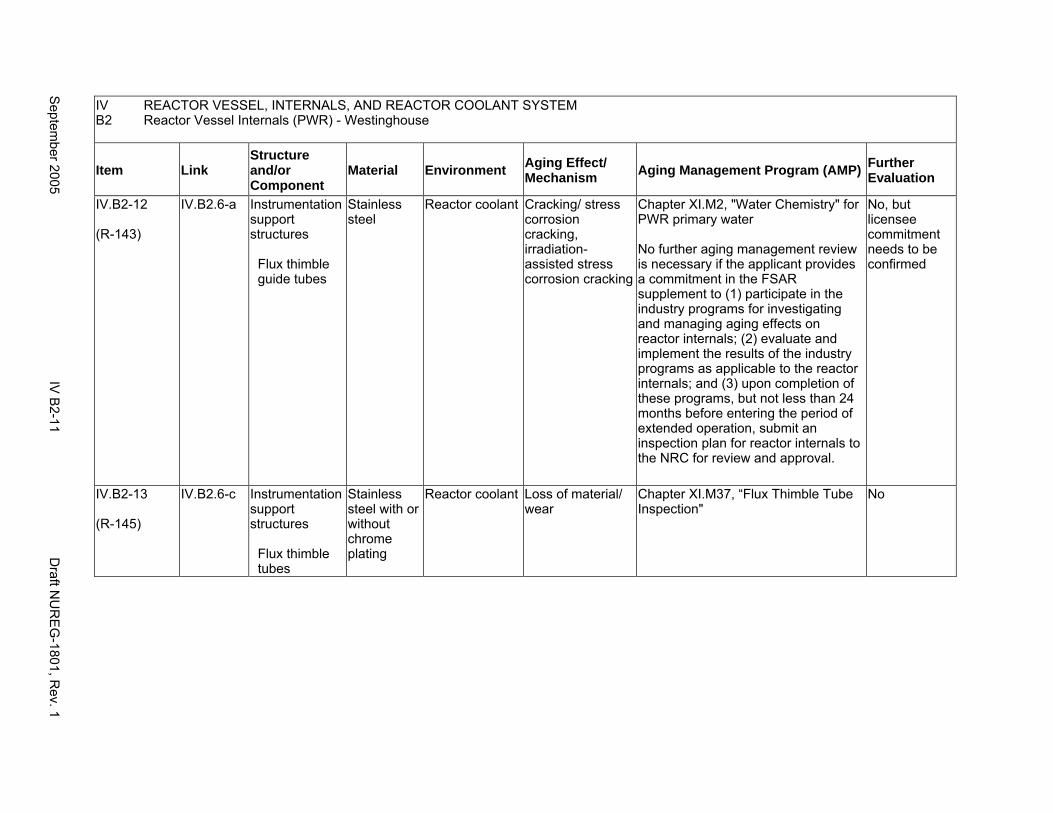
IV REACTOR VESSEL, INTERNALS, AND REACTOR COOLANT SYSTEM B2 Reactor Vessel Internals (PWR) - Westinghouse
Item Link Structure and/or Component
Material Environment Aging Effect/ Mechanism Aging Management Program (AMP) Further
Evaluation
IV.B2-12
(R-143)
IV.B2.6-a Instrumentation support structures
Flux thimble guide tubes
Stainless steel
Reactor coolant Cracking/ stress corrosion cracking, irradiation-assisted stress corrosion cracking
Chapter XI.M2, "Water Chemistry" for PWR primary water
No further aging management review is necessary if the applicant provides a commitment in the FSAR supplement to (1) participate in the industry programs for investigating and managing aging effects on reactor internals; (2) evaluate and implement the results of the industry programs as applicable to the reactor internals; and (3) upon completion of these programs, but not less than 24 months before entering the period of extended operation, submit an inspection plan for reactor internals to the NRC for review and approval.
No, but licensee commitment needs to be confirmed
IV.B2-13
(R-145)
IV.B2.6-c Instrumentation support structures
Flux thimble tubes
Stainless steel with or without chrome plating
Reactor coolant Loss of material/ wear
Chapter XI.M37, “Flux Thimble Tube Inspection"
No
Septem
ber 2005 IV
B2-11
Draft N
UR
EG
-1801, Rev. 1
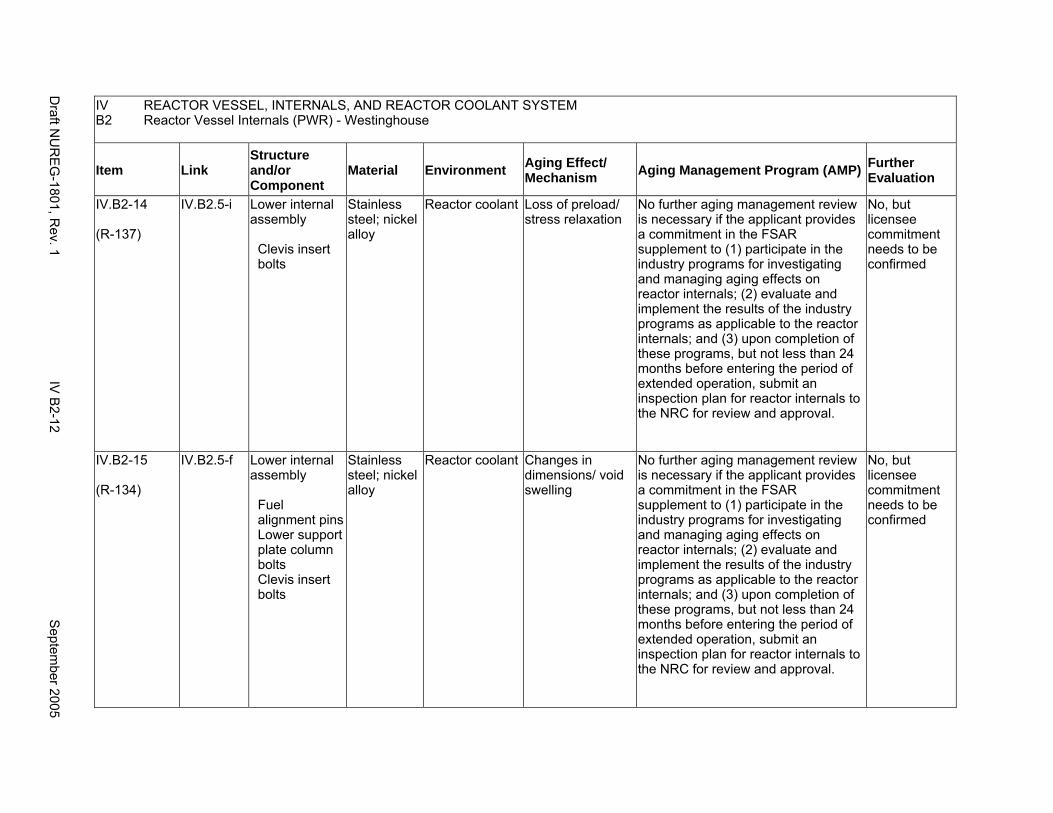
IV REACTOR VESSEL, INTERNALS, AND REACTOR COOLANT SYSTEM B2 Reactor Vessel Internals (PWR) - Westinghouse
Item Link Structure and/or Component
Material Environment Aging Effect/ Mechanism Aging Management Program (AMP) Further
Evaluation
IV.B2-14
(R-137)
IV.B2.5-i Lower internal assembly
Clevis insert bolts
Stainless steel; nickel alloy
Reactor coolant Loss of preload/ stress relaxation
No further aging management review is necessary if the applicant provides a commitment in the FSAR supplement to (1) participate in the industry programs for investigating and managing aging effects on reactor internals; (2) evaluate and implement the results of the industry programs as applicable to the reactor internals; and (3) upon completion of these programs, but not less than 24 months before entering the period of extended operation, submit an inspection plan for reactor internals to the NRC for review and approval.
No, but licensee commitment needs to be confirmed
IV.B2-15
(R-134)
IV.B2.5-f Lower internal assembly
Fuel alignment pins Lower support plate column bolts Clevis insert bolts
Stainless steel; nickel alloy
Reactor coolant Changes in dimensions/ void swelling
No further aging management review is necessary if the applicant provides a commitment in the FSAR supplement to (1) participate in the industry programs for investigating and managing aging effects on reactor internals; (2) evaluate and implement the results of the industry programs as applicable to the reactor internals; and (3) upon completion of these programs, but not less than 24 months before entering the period of extended operation, submit an inspection plan for reactor internals to the NRC for review and approval.
No, but licensee commitment needs to be confirmed
Draft N
UR
EG
-1801, Rev. 1
IV B
2-12 S
eptember 2005
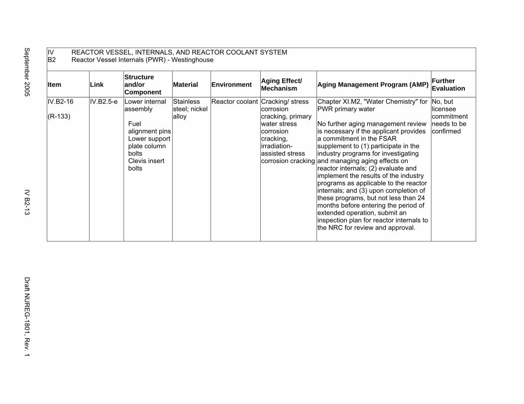
IV REACTOR VESSEL, INTERNALS, AND REACTOR COOLANT SYSTEM B2 Reactor Vessel Internals (PWR) - Westinghouse
Item Link Structure and/or Component
Material Environment Aging Effect/ Mechanism Aging Management Program (AMP) Further
Evaluation
IV.B2-16
(R-133)
IV.B2.5-e Lower internal assembly
Fuel alignment pins Lower support plate column bolts Clevis insert bolts
Stainless steel; nickel alloy
Reactor coolant Cracking/ stress corrosion cracking, primary water stress corrosion cracking, irradiation-assisted stress corrosion cracking
Chapter XI.M2, "Water Chemistry" for PWR primary water
No further aging management review is necessary if the applicant provides a commitment in the FSAR supplement to (1) participate in the industry programs for investigating and managing aging effects on reactor internals; (2) evaluate and implement the results of the industry programs as applicable to the reactor internals; and (3) upon completion of these programs, but not less than 24 months before entering the period of extended operation, submit an inspection plan for reactor internals to the NRC for review and approval.
No, but licensee commitment needs to be confirmed
Septem
ber 2005 IV
B2-13
Draft N
UR
EG
-1801, Rev. 1
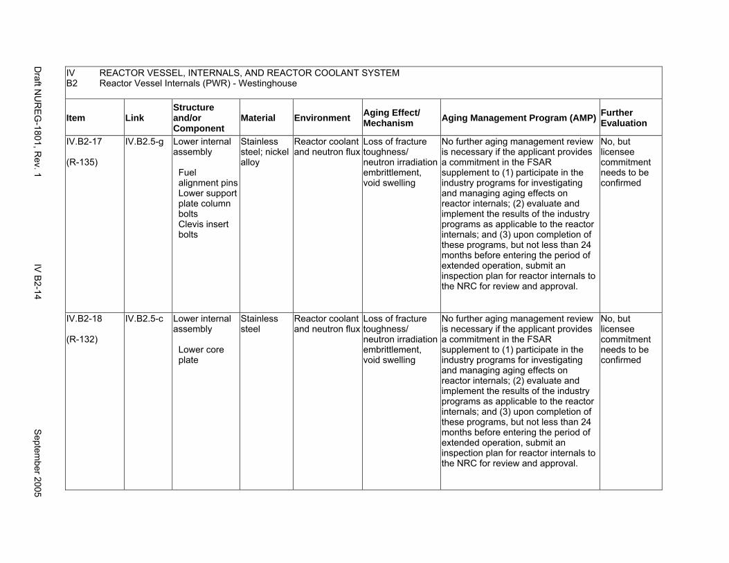
IV REACTOR VESSEL, INTERNALS, AND REACTOR COOLANT SYSTEM B2 Reactor Vessel Internals (PWR) - Westinghouse
Item Link Structure and/or Component
Material Environment Aging Effect/ Mechanism Aging Management Program (AMP) Further
Evaluation
IV.B2-17
(R-135)
IV.B2.5-g Lower internal assembly
Fuel alignment pins Lower support plate column bolts Clevis insert bolts
Stainless steel; nickel alloy
Reactor coolant and neutron flux
Loss of fracture toughness/ neutron irradiation embrittlement, void swelling
No further aging management review is necessary if the applicant provides a commitment in the FSAR supplement to (1) participate in the industry programs for investigating and managing aging effects on reactor internals; (2) evaluate and implement the results of the industry programs as applicable to the reactor internals; and (3) upon completion of these programs, but not less than 24 months before entering the period of extended operation, submit an inspection plan for reactor internals to the NRC for review and approval.
No, but licensee commitment needs to be confirmed
IV.B2-18
(R-132)
IV.B2.5-c Lower internal assembly
Lower core plate
Stainless steel
Reactor coolant and neutron flux
Loss of fracture toughness/ neutron irradiation embrittlement, void swelling
No further aging management review is necessary if the applicant provides a commitment in the FSAR supplement to (1) participate in the industry programs for investigating and managing aging effects on reactor internals; (2) evaluate and implement the results of the industry programs as applicable to the reactor internals; and (3) upon completion of these programs, but not less than 24 months before entering the period of extended operation, submit an inspection plan for reactor internals to the NRC for review and approval.
No, but licensee commitment needs to be confirmed
Draft N
UR
EG
-1801, Rev. 1
IV B
2-14 S
eptember 2005
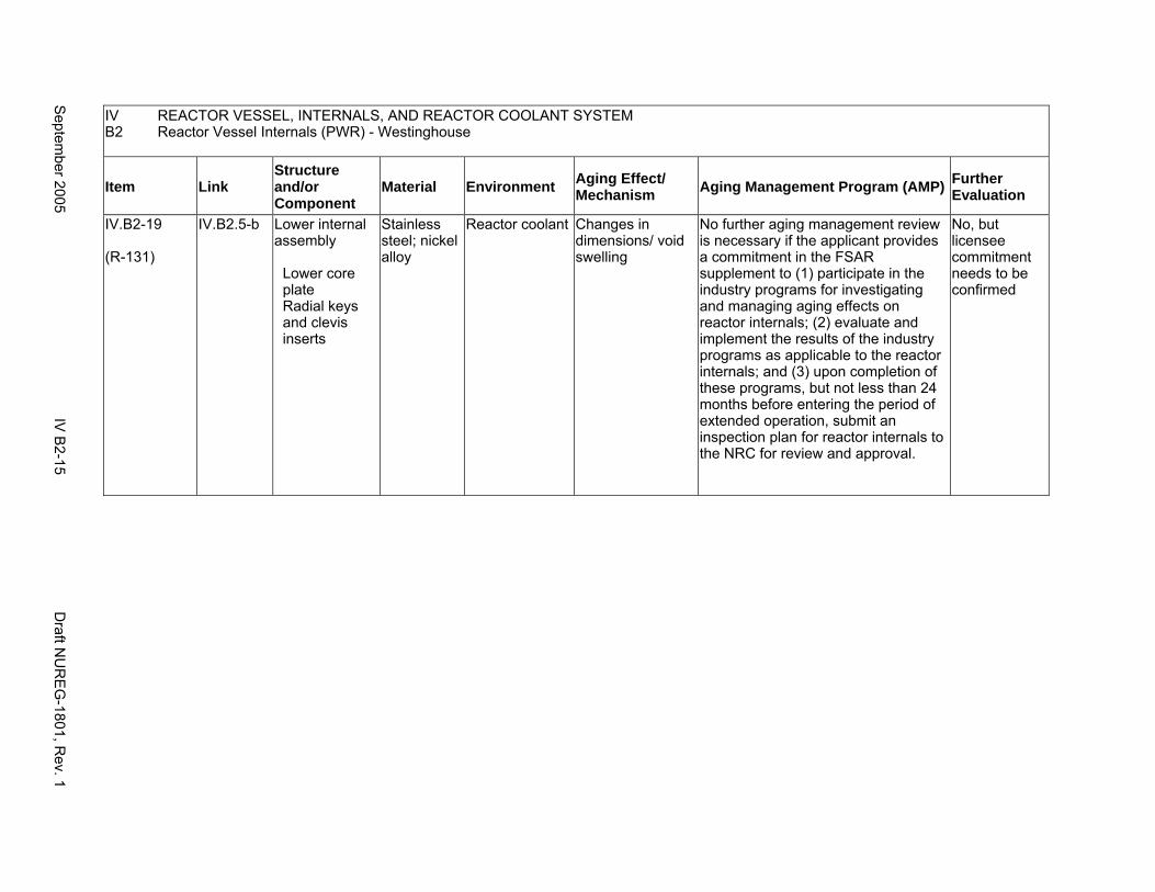
IV REACTOR VESSEL, INTERNALS, AND REACTOR COOLANT SYSTEM B2 Reactor Vessel Internals (PWR) - Westinghouse
Item Link Structure and/or Component
Material Environment Aging Effect/ Mechanism Aging Management Program (AMP) Further
Evaluation
IV.B2-19
(R-131)
IV.B2.5-b Lower internal assembly
Lower core plate Radial keys and clevis inserts
Stainless steel; nickel alloy
Reactor coolant Changes in dimensions/ void swelling
No further aging management review is necessary if the applicant provides a commitment in the FSAR supplement to (1) participate in the industry programs for investigating and managing aging effects on reactor internals; (2) evaluate and implement the results of the industry programs as applicable to the reactor internals; and (3) upon completion of these programs, but not less than 24 months before entering the period of extended operation, submit an inspection plan for reactor internals to the NRC for review and approval.
No, but licensee commitment needs to be confirmed
Septem
ber 2005 IV
B2-15
Draft N
UR
EG
-1801, Rev. 1
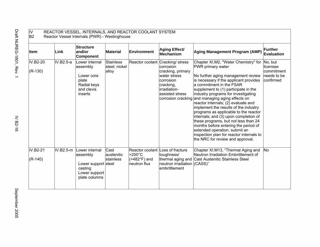
IV REACTOR VESSEL, INTERNALS, AND REACTOR COOLANT SYSTEM B2 Reactor Vessel Internals (PWR) - Westinghouse
Item Link Structure and/or Component
Material Environment Aging Effect/ Mechanism Aging Management Program (AMP) Further
Evaluation
IV.B2-20
(R-130)
IV.B2.5-a Lower internal assembly
Lower core plate Radial keys and clevis inserts
Stainless steel; nickel alloy
Reactor coolant Cracking/ stress corrosion cracking, primary water stress corrosion cracking, irradiation-assisted stress corrosion cracking
Chapter XI.M2, "Water Chemistry" for PWR primary water
No further aging management review is necessary if the applicant provides a commitment in the FSAR supplement to (1) participate in the industry programs for investigating and managing aging effects on reactor internals; (2) evaluate and implement the results of the industry programs as applicable to the reactor internals; and (3) upon completion of these programs, but not less than 24 months before entering the period of extended operation, submit an inspection plan for reactor internals to the NRC for review and approval.
No, but licensee commitment needs to be confirmed
IV.B2-21
(R-140)
IV.B2.5-m Lower internal assembly
Lower support casting Lower support plate columns
Cast austenitic stainless steel
Reactor coolant >250°C (>482°F) and neutron flux
Loss of fracture toughness/ thermal aging and neutron irradiation embrittlement
Chapter XI.M13, “Thermal Aging and Neutron Irradiation Embrittlement of Cast Austenitic Stainless Steel (CASS)”
No
Draft N
UR
EG
-1801, Rev. 1
IV B
2-16 S
eptember 2005
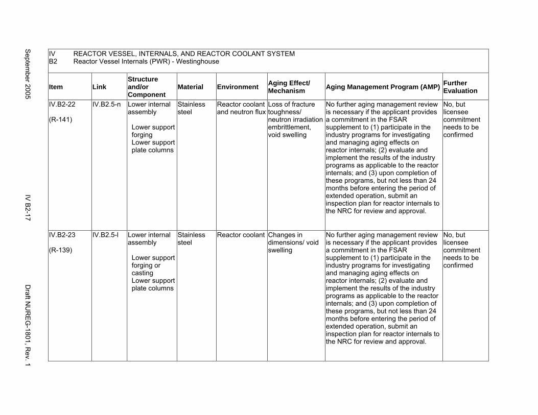
IV REACTOR VESSEL, INTERNALS, AND REACTOR COOLANT SYSTEM B2 Reactor Vessel Internals (PWR) - Westinghouse
Item Link Structure and/or Component
Material Environment Aging Effect/ Mechanism Aging Management Program (AMP) Further
Evaluation
IV.B2-22
(R-141)
IV.B2.5-n Lower internal assembly
Lower support forging Lower support plate columns
Stainless steel
Reactor coolant and neutron flux
Loss of fracture toughness/ neutron irradiation embrittlement, void swelling
No further aging management review is necessary if the applicant provides a commitment in the FSAR supplement to (1) participate in the industry programs for investigating and managing aging effects on reactor internals; (2) evaluate and implement the results of the industry programs as applicable to the reactor internals; and (3) upon completion of these programs, but not less than 24 months before entering the period of extended operation, submit an inspection plan for reactor internals to the NRC for review and approval.
No, but licensee commitment needs to be confirmed
IV.B2-23
(R-139)
IV.B2.5-l Lower internal assembly
Lower support forging or casting Lower support plate columns
Stainless steel
Reactor coolant Changes in dimensions/ void swelling
No further aging management review is necessary if the applicant provides a commitment in the FSAR supplement to (1) participate in the industry programs for investigating and managing aging effects on reactor internals; (2) evaluate and implement the results of the industry programs as applicable to the reactor internals; and (3) upon completion of these programs, but not less than 24 months before entering the period of extended operation, submit an inspection plan for reactor internals to the NRC for review and approval.
No, but licensee commitment needs to be confirmed
Septem
ber 2005 IV
B2-17
Draft N
UR
EG
-1801, Rev. 1
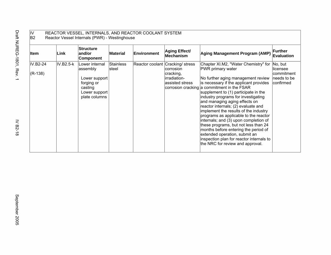
IV REACTOR VESSEL, INTERNALS, AND REACTOR COOLANT SYSTEM B2 Reactor Vessel Internals (PWR) - Westinghouse
Item Link Structure and/or Component
Material Environment Aging Effect/ Mechanism Aging Management Program (AMP) Further
Evaluation
IV.B2-24
(R-138)
IV.B2.5-k Lower internal assembly
Lower support forging or casting Lower support plate columns
Stainless steel
Reactor coolant Cracking/ stress corrosion cracking, irradiation-assisted stress corrosion cracking
Chapter XI.M2, "Water Chemistry" for PWR primary water
No further aging management review is necessary if the applicant provides a commitment in the FSAR supplement to (1) participate in the industry programs for investigating and managing aging effects on reactor internals; (2) evaluate and implement the results of the industry programs as applicable to the reactor internals; and (3) upon completion of these programs, but not less than 24 months before entering the period of extended operation, submit an inspection plan for reactor internals to the NRC for review and approval.
No, but licensee commitment needs to be confirmed
Draft N
UR
EG
-1801, Rev. 1
IV B
2-18 S
eptember 2005
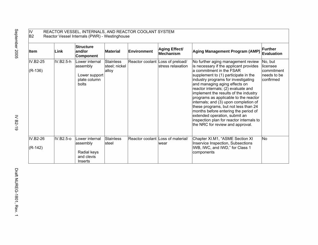
IV REACTOR VESSEL, INTERNALS, AND REACTOR COOLANT SYSTEM B2 Reactor Vessel Internals (PWR) - Westinghouse
Item Link Structure and/or Component
Material Environment Aging Effect/ Mechanism Aging Management Program (AMP) Further
Evaluation
IV.B2-25
(R-136)
IV.B2.5-h Lower internal assembly
Lower support plate column bolts
Stainless steel; nickel alloy
Reactor coolant Loss of preload/ stress relaxation
No further aging management review is necessary if the applicant provides a commitment in the FSAR supplement to (1) participate in the industry programs for investigating and managing aging effects on reactor internals; (2) evaluate and implement the results of the industry programs as applicable to the reactor internals; and (3) upon completion of these programs, but not less than 24 months before entering the period of extended operation, submit an inspection plan for reactor internals to the NRC for review and approval.
No, but licensee commitment needs to be confirmed
IV.B2-26
(R-142)
IV.B2.5-o Lower internal assembly
Radial keys and clevis Inserts
Stainless steel
Reactor coolant Loss of material/ wear
Chapter XI.M1, “ASME Section XI Inservice Inspection, Subsections IWB, IWC, and IWD,” for Class 1 components
No
Septem
ber 2005 IV
B2-19
Draft N
UR
EG
-1801, Rev. 1
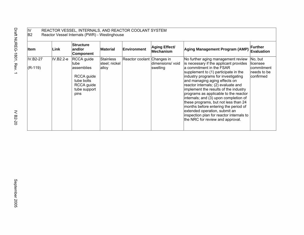
IV REACTOR VESSEL, INTERNALS, AND REACTOR COOLANT SYSTEM B2 Reactor Vessel Internals (PWR) - Westinghouse
Item Link Structure and/or Component
Material Environment Aging Effect/ Mechanism Aging Management Program (AMP) Further
Evaluation
IV.B2-27
(R-119)
IV.B2.2-e RCCA guide tube assemblies
RCCA guide tube bolts RCCA guide tube support pins
Stainless steel; nickel alloy
Reactor coolant Changes in dimensions/ void swelling
No further aging management review is necessary if the applicant provides a commitment in the FSAR supplement to (1) participate in the industry programs for investigating and managing aging effects on reactor internals; (2) evaluate and implement the results of the industry programs as applicable to the reactor internals; and (3) upon completion of these programs, but not less than 24 months before entering the period of extended operation, submit an inspection plan for reactor internals to the NRC for review and approval.
No, but licensee commitment needs to be confirmed
Draft N
UR
EG
-1801, Rev. 1
IV B
2-20 S
eptember 2005
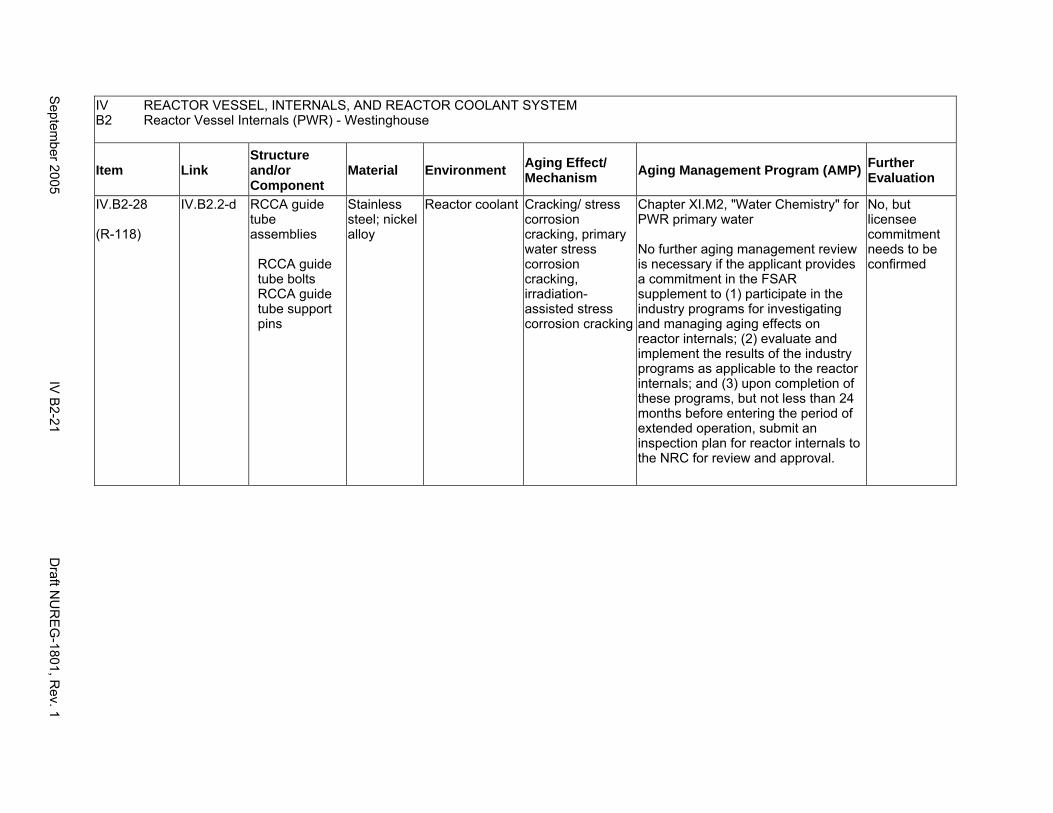
IV REACTOR VESSEL, INTERNALS, AND REACTOR COOLANT SYSTEM B2 Reactor Vessel Internals (PWR) - Westinghouse
Item Link Structure and/or Component
Material Environment Aging Effect/ Mechanism Aging Management Program (AMP) Further
Evaluation
IV.B2-28
(R-118)
IV.B2.2-d RCCA guide tube assemblies
RCCA guide tube bolts RCCA guide tube support pins
Stainless steel; nickel alloy
Reactor coolant Cracking/ stress corrosion cracking, primary water stress corrosion cracking, irradiation-assisted stress corrosion cracking
Chapter XI.M2, "Water Chemistry" for PWR primary water
No further aging management review is necessary if the applicant provides a commitment in the FSAR supplement to (1) participate in the industry programs for investigating and managing aging effects on reactor internals; (2) evaluate and implement the results of the industry programs as applicable to the reactor internals; and (3) upon completion of these programs, but not less than 24 months before entering the period of extended operation, submit an inspection plan for reactor internals to the NRC for review and approval.
No, but licensee commitment needs to be confirmed
Septem
ber 2005 IV
B2-21
Draft N
UR
EG
-1801, Rev. 1
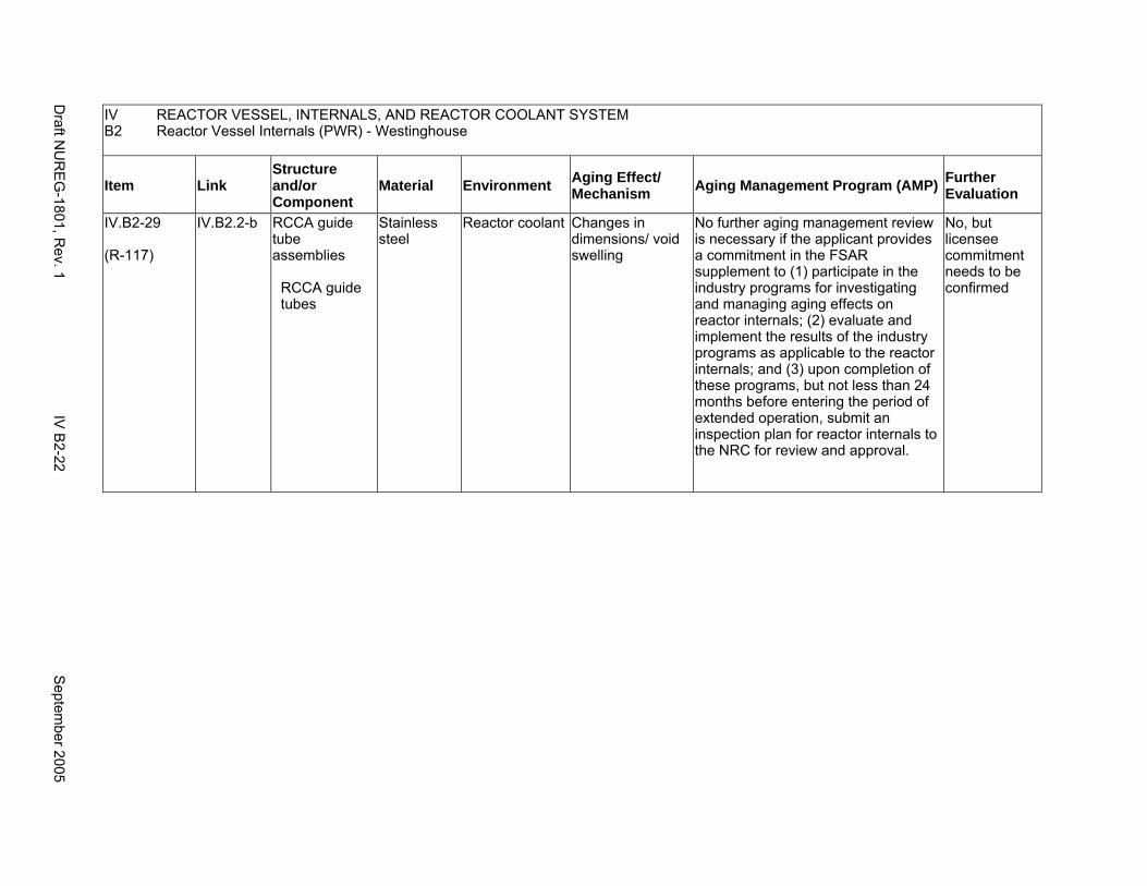
IV REACTOR VESSEL, INTERNALS, AND REACTOR COOLANT SYSTEM B2 Reactor Vessel Internals (PWR) - Westinghouse
Item Link Structure and/or Component
Material Environment Aging Effect/ Mechanism Aging Management Program (AMP) Further
Evaluation
IV.B2-29
(R-117)
IV.B2.2-b RCCA guide tube assemblies
RCCA guide tubes
Stainless steel
Reactor coolant Changes in dimensions/ void swelling
No further aging management review is necessary if the applicant provides a commitment in the FSAR supplement to (1) participate in the industry programs for investigating and managing aging effects on reactor internals; (2) evaluate and implement the results of the industry programs as applicable to the reactor internals; and (3) upon completion of these programs, but not less than 24 months before entering the period of extended operation, submit an inspection plan for reactor internals to the NRC for review and approval.
No, but licensee commitment needs to be confirmed
Draft N
UR
EG
-1801, Rev. 1
IV B
2-22 S
eptember 2005
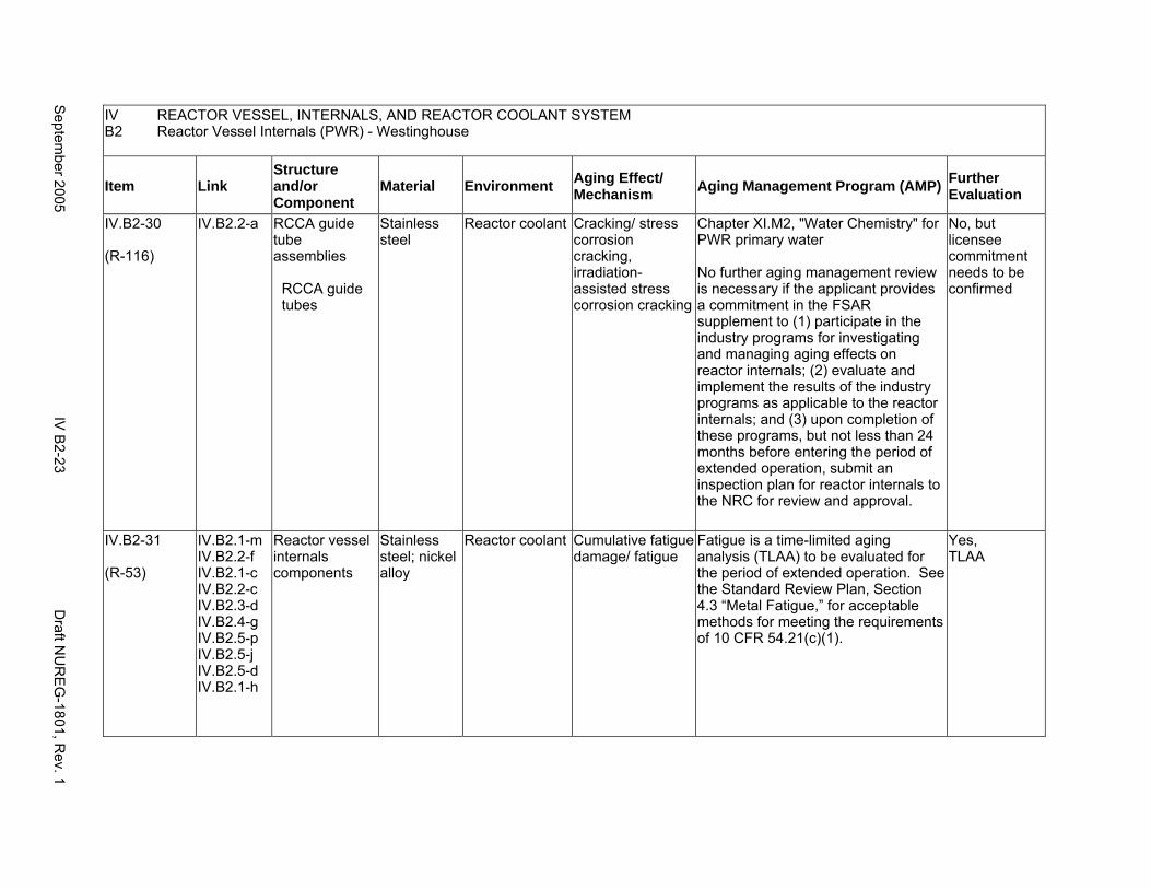
IV REACTOR VESSEL, INTERNALS, AND REACTOR COOLANT SYSTEM B2 Reactor Vessel Internals (PWR) - Westinghouse
Item Link Structure and/or Component
Material Environment Aging Effect/ Mechanism Aging Management Program (AMP) Further
Evaluation
IV.B2-30
(R-116)
IV.B2.2-a RCCA guide tube assemblies
RCCA guide tubes
Stainless steel
Reactor coolant Cracking/ stress corrosion cracking, irradiation-assisted stress corrosion cracking
Chapter XI.M2, "Water Chemistry" for PWR primary water
No further aging management review is necessary if the applicant provides a commitment in the FSAR supplement to (1) participate in the industry programs for investigating and managing aging effects on reactor internals; (2) evaluate and implement the results of the industry programs as applicable to the reactor internals; and (3) upon completion of these programs, but not less than 24 months before entering the period of extended operation, submit an inspection plan for reactor internals to the NRC for review and approval.
No, but licensee commitment needs to be confirmed
IV.B2-31
(R-53)
IV.B2.1-m IV.B2.2-f IV.B2.1-c IV.B2.2-c IV.B2.3-d IV.B2.4-g IV.B2.5-p IV.B2.5-j IV.B2.5-d IV.B2.1-h
Reactor vessel internals components
Stainless steel; nickel alloy
Reactor coolant Cumulative fatigue damage/ fatigue
Fatigue is a time-limited aging analysis (TLAA) to be evaluated for the period of extended operation. See the Standard Review Plan, Section 4.3 “Metal Fatigue,” for acceptable methods for meeting the requirements of 10 CFR 54.21(c)(1).
Yes, TLAA
Septem
ber 2005 IV
B2-23
Draft N
UR
EG
-1801, Rev. 1
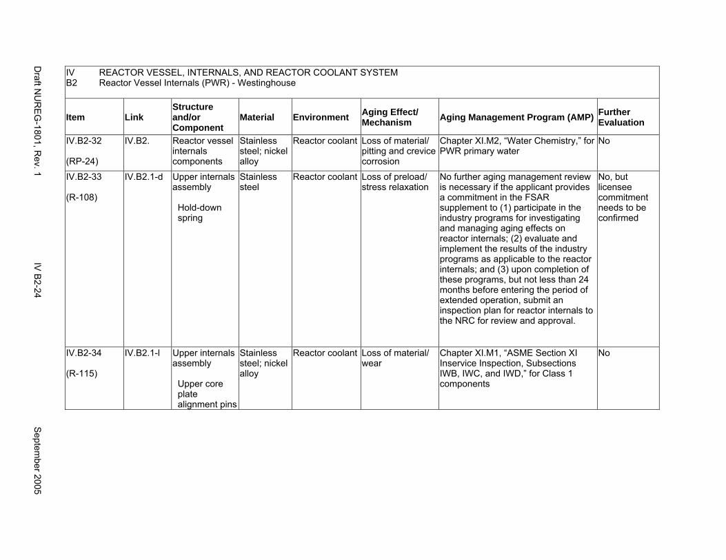
IV REACTOR VESSEL, INTERNALS, AND REACTOR COOLANT SYSTEM B2 Reactor Vessel Internals (PWR) - Westinghouse
Item Link Structure and/or Component
Material Environment Aging Effect/ Mechanism Aging Management Program (AMP) Further
Evaluation
IV.B2-32
(RP-24)
IV.B2. Reactor vessel internals components
Stainless steel; nickel alloy
Reactor coolant Loss of material/ pitting and crevice corrosion
Chapter XI.M2, “Water Chemistry,” for PWR primary water
No
IV.B2-33
(R-108)
IV.B2.1-d Upper internals assembly
Hold-down spring
Stainless steel
Reactor coolant Loss of preload/ stress relaxation
No further aging management review is necessary if the applicant provides a commitment in the FSAR supplement to (1) participate in the industry programs for investigating and managing aging effects on reactor internals; (2) evaluate and implement the results of the industry programs as applicable to the reactor internals; and (3) upon completion of these programs, but not less than 24 months before entering the period of extended operation, submit an inspection plan for reactor internals to the NRC for review and approval.
No, but licensee commitment needs to be confirmed
IV.B2-34
(R-115)
IV.B2.1-l Upper internals assembly
Upper core plate alignment pins
Stainless steel; nickel alloy
Reactor coolant Loss of material/ wear
Chapter XI.M1, “ASME Section XI Inservice Inspection, Subsections IWB, IWC, and IWD,” for Class 1 components
No
Draft N
UR
EG
-1801, Rev. 1
IV B
2-24 S
eptember 2005
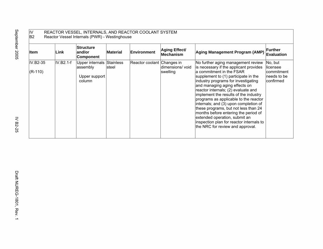
IV REACTOR VESSEL, INTERNALS, AND REACTOR COOLANT SYSTEM B2 Reactor Vessel Internals (PWR) - Westinghouse
Item Link Structure and/or Component
Material Environment Aging Effect/ Mechanism Aging Management Program (AMP) Further
Evaluation
IV.B2-35
(R-110)
IV.B2.1-f Upper internals assembly
Upper support column
Stainless steel
Reactor coolant Changes in dimensions/ void swelling
No further aging management review is necessary if the applicant provides a commitment in the FSAR supplement to (1) participate in the industry programs for investigating and managing aging effects on reactor internals; (2) evaluate and implement the results of the industry programs as applicable to the reactor internals; and (3) upon completion of these programs, but not less than 24 months before entering the period of extended operation, submit an inspection plan for reactor internals to the NRC for review and approval.
No, but licensee commitment needs to be confirmed
Septem
ber 2005 IV
B2-25
Draft N
UR
EG
-1801, Rev. 1
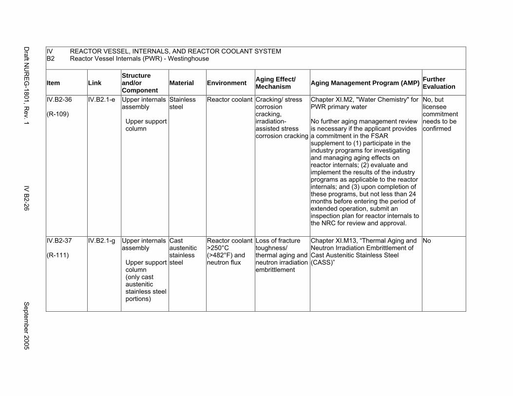
IV REACTOR VESSEL, INTERNALS, AND REACTOR COOLANT SYSTEM B2 Reactor Vessel Internals (PWR) - Westinghouse
Item Link Structure and/or Component
Material Environment Aging Effect/ Mechanism Aging Management Program (AMP) Further
Evaluation
IV.B2-36
(R-109)
IV.B2.1-e Upper internals assembly
Upper support column
Stainless steel
Reactor coolant Cracking/ stress corrosion cracking, irradiation-assisted stress corrosion cracking
Chapter XI.M2, "Water Chemistry" for PWR primary water
No further aging management review is necessary if the applicant provides a commitment in the FSAR supplement to (1) participate in the industry programs for investigating and managing aging effects on reactor internals; (2) evaluate and implement the results of the industry programs as applicable to the reactor internals; and (3) upon completion of these programs, but not less than 24 months before entering the period of extended operation, submit an inspection plan for reactor internals to the NRC for review and approval.
No, but licensee commitment needs to be confirmed
IV.B2-37
(R-111)
IV.B2.1-g Upper internals assembly
Upper support column (only cast austenitic stainless steel portions)
Cast austenitic stainless steel
Reactor coolant >250°C (>482°F) and neutron flux
Loss of fracture toughness/ thermal aging and neutron irradiation embrittlement
Chapter XI.M13, “Thermal Aging and Neutron Irradiation Embrittlement of Cast Austenitic Stainless Steel (CASS)”
No
Draft N
UR
EG
-1801, Rev. 1
IV B
2-26 S
eptember 2005
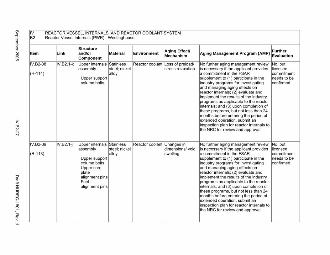
IV REACTOR VESSEL, INTERNALS, AND REACTOR COOLANT SYSTEM B2 Reactor Vessel Internals (PWR) - Westinghouse
Item Link Structure and/or Component
Material Environment Aging Effect/ Mechanism Aging Management Program (AMP) Further
Evaluation
IV.B2-38
(R-114)
IV.B2.1-k Upper internals assembly
Upper support column bolts
Stainless steel; nickel alloy
Reactor coolant Loss of preload/ stress relaxation
No further aging management review is necessary if the applicant provides a commitment in the FSAR supplement to (1) participate in the industry programs for investigating and managing aging effects on reactor internals; (2) evaluate and implement the results of the industry programs as applicable to the reactor internals; and (3) upon completion of these programs, but not less than 24 months before entering the period of extended operation, submit an inspection plan for reactor internals to the NRC for review and approval.
No, but licensee commitment needs to be confirmed
IV.B2-39
(R-113)
IV.B2.1-j Upper internals assembly
Upper support column bolts Upper core plate alignment pins Fuel alignment pins
Stainless steel; nickel alloy
Reactor coolant Changes in dimensions/ void swelling
No further aging management review is necessary if the applicant provides a commitment in the FSAR supplement to (1) participate in the industry programs for investigating and managing aging effects on reactor internals; (2) evaluate and implement the results of the industry programs as applicable to the reactor internals; and (3) upon completion of these programs, but not less than 24 months before entering the period of extended operation, submit an inspection plan for reactor internals to the NRC for review and approval.
No, but licensee commitment needs to be confirmed
Septem
ber 2005 IV
B2-27
Draft N
UR
EG
-1801, Rev. 1
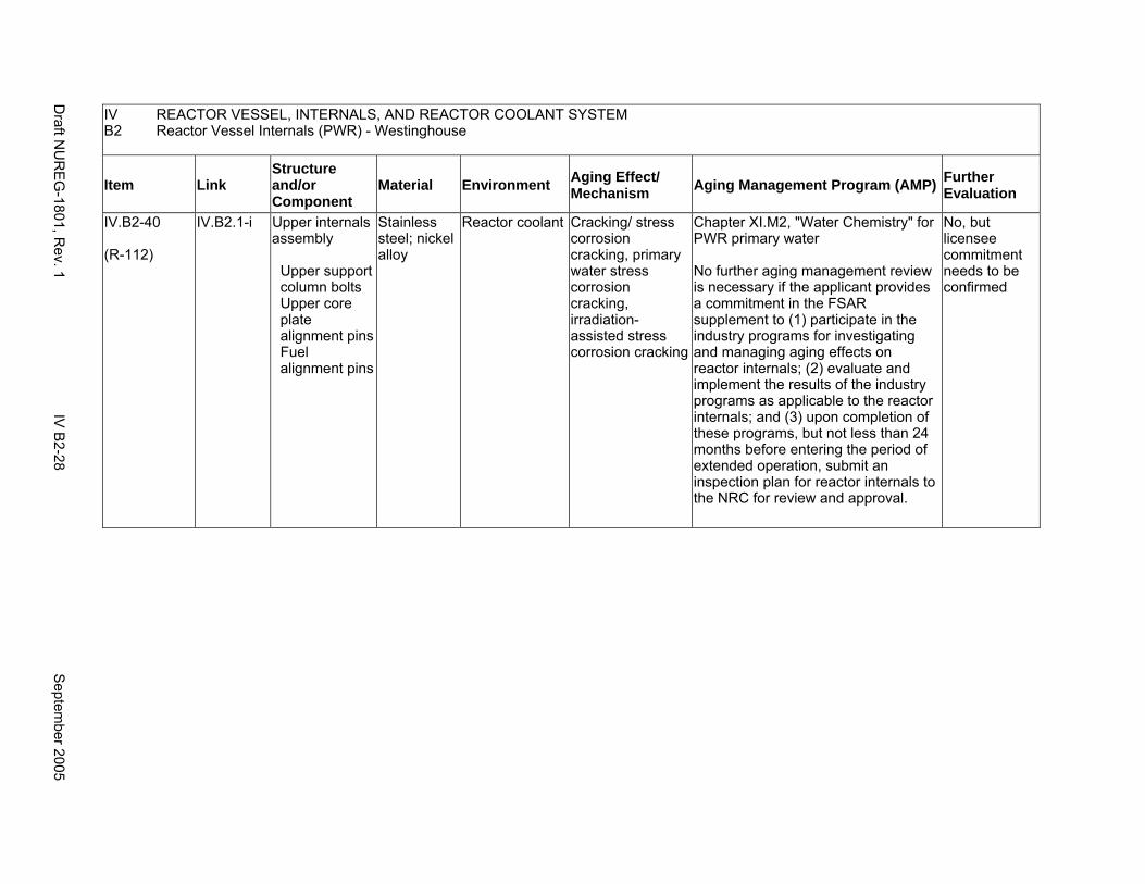
IV REACTOR VESSEL, INTERNALS, AND REACTOR COOLANT SYSTEM B2 Reactor Vessel Internals (PWR) - Westinghouse
Item Link Structure and/or Component
Material Environment Aging Effect/ Mechanism Aging Management Program (AMP) Further
Evaluation
IV.B2-40
(R-112)
IV.B2.1-i Upper internals assembly
Upper support column bolts Upper core plate alignment pins Fuel alignment pins
Stainless steel; nickel alloy
Reactor coolant Cracking/ stress corrosion cracking, primary water stress corrosion cracking, irradiation-assisted stress corrosion cracking
Chapter XI.M2, "Water Chemistry" for PWR primary water
No further aging management review is necessary if the applicant provides a commitment in the FSAR supplement to (1) participate in the industry programs for investigating and managing aging effects on reactor internals; (2) evaluate and implement the results of the industry programs as applicable to the reactor internals; and (3) upon completion of these programs, but not less than 24 months before entering the period of extended operation, submit an inspection plan for reactor internals to the NRC for review and approval.
No, but licensee commitment needs to be confirmed
Draft N
UR
EG
-1801, Rev. 1
IV B
2-28 S
eptember 2005
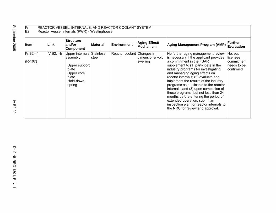
IV REACTOR VESSEL, INTERNALS, AND REACTOR COOLANT SYSTEM B2 Reactor Vessel Internals (PWR) - Westinghouse
Item Link Structure and/or Component
Material Environment Aging Effect/ Mechanism Aging Management Program (AMP) Further
Evaluation
IV.B2-41
(R-107)
IV.B2.1-b Upper internals assembly
Upper support plate Upper core plate Hold-down spring
Stainless steel
Reactor coolant Changes in dimensions/ void swelling
No further aging management review is necessary if the applicant provides a commitment in the FSAR supplement to (1) participate in the industry programs for investigating and managing aging effects on reactor internals; (2) evaluate and implement the results of the industry programs as applicable to the reactor internals; and (3) upon completion of these programs, but not less than 24 months before entering the period of extended operation, submit an inspection plan for reactor internals to the NRC for review and approval.
No, but licensee commitment needs to be confirmed
Septem
ber 2005 IV
B2-29
Draft N
UR
EG
-1801, Rev. 1

IV REACTOR VESSEL, INTERNALS, AND REACTOR COOLANT SYSTEM B2 Reactor Vessel Internals (PWR) - Westinghouse
Item Link Structure and/or Component
Material Environment Aging Effect/ Mechanism Aging Management Program (AMP) Further
Evaluation
IV.B2-42
(R-106)
IV.B2.1-a Upper internals assembly
Upper support plate Upper core plate Hold-down spring
Stainless steel
Reactor coolant Cracking/ stress corrosion cracking, irradiation-assisted stress corrosion cracking
Chapter XI.M2, "Water Chemistry" for PWR primary water
No further aging management review is necessary if the applicant provides a commitment in the FSAR supplement to (1) participate in the industry programs for investigating and managing aging effects on reactor internals; (2) evaluate and implement the results of the industry programs as applicable to the reactor internals; and (3) upon completion of these programs, but not less than 24 months before entering the period of extended operation, submit an inspection plan for reactor internals to the NRC for review and approval.
No, but licensee commitment needs to be confirmed
Draft N
UR
EG
-1801, Rev. 1
IV B
2-30 S
eptember 2005
B3. REACTOR VESSEL INTERNALS (PWR) - COMBUSTION ENGINEERING
Systems, Structures, and Components
This section addresses the Combustion Engineering pressurized water reactor (PWR) vessel internals and consists of the upper internals assembly, the control element assembly (CEA), shroud assemblies, the core support barrel, the core shroud assembly, and the lower internal assembly. Based on Regulatory Guide 1.26, “Quality Group Classifications and Standards for Water-, Steam-, and Radioactive-Waste-Containing Components of Nuclear Power Plants,” all structures and components that comprise the reactor vessel are governed by Group A or B Quality Standards.
Common miscellaneous material/environment combinations where aging effects are not expected to degrade the ability of the structure or component to perform its intended function for the extended period of operation are included in IV.E.
System Interfaces
The systems that interface with the reactor vessel internals include the reactor pressure vessel (IV.A2).
September 2005 IV B3-1 Draft NUREG-1801, Rev. 1
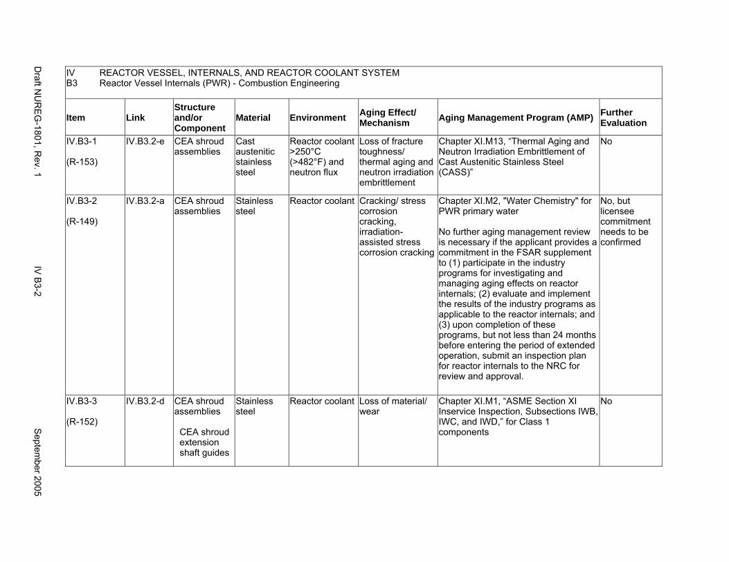
IV B3
REACTOR VESSEL, INTERNALS, AND REACTOR COOLANT SYSTEM Reactor Vessel Internals (PWR) - Combustion Engineering
Item Link Structure and/or Component
Material Environment Aging Effect/ Mechanism Aging Management Program (AMP) Further
Evaluation
IV.B3-1
(R-153)
IV.B3.2-e CEA shroud assemblies
Cast austenitic stainless steel
Reactor coolant >250°C (>482°F) and neutron flux
Loss of fracture toughness/ thermal aging and neutron irradiation embrittlement
Chapter XI.M13, “Thermal Aging and Neutron Irradiation Embrittlement of Cast Austenitic Stainless Steel (CASS)”
No
IV.B3-2
(R-149)
IV.B3.2-a CEA shroud assemblies
Stainless steel
Reactor coolant Cracking/ stress corrosion cracking, irradiation-assisted stress corrosion cracking
Chapter XI.M2, "Water Chemistry" for PWR primary water
No further aging management review is necessary if the applicant provides a commitment in the FSAR supplement to (1) participate in the industry programs for investigating and managing aging effects on reactor internals; (2) evaluate and implement the results of the industry programs as applicable to the reactor internals; and (3) upon completion of these programs, but not less than 24 months before entering the period of extended operation, submit an inspection plan for reactor internals to the NRC for review and approval.
No, but licensee commitment needs to be confirmed
IV.B3-3
(R-152)
IV.B3.2-d CEA shroud assemblies
CEA shroud extension shaft guides
Stainless steel
Reactor coolant Loss of material/ wear
Chapter XI.M1, “ASME Section XI Inservice Inspection, Subsections IWB, IWC, and IWD,” for Class 1 components
No
Draft N
UR
EG
-1801, Rev. 1
IV B
3-2 S
eptember 2005
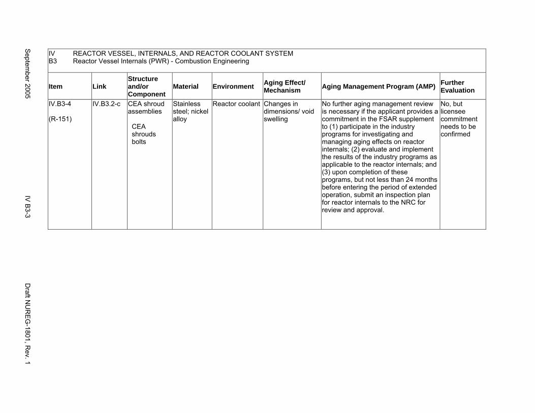
IV REACTOR VESSEL, INTERNALS, AND REACTOR COOLANT SYSTEM B3 Reactor Vessel Internals (PWR) - Combustion Engineering
Item Link Structure and/or Component
Material Environment Aging Effect/ Mechanism Aging Management Program (AMP) Further
Evaluation
IV.B3-4
(R-151)
IV.B3.2-c CEA shroud assemblies
CEA shrouds bolts
Stainless steel; nickel alloy
Reactor coolant Changes in dimensions/ void swelling
No further aging management review is necessary if the applicant provides a commitment in the FSAR supplement to (1) participate in the industry programs for investigating and managing aging effects on reactor internals; (2) evaluate and implement the results of the industry programs as applicable to the reactor internals; and (3) upon completion of these programs, but not less than 24 months before entering the period of extended operation, submit an inspection plan for reactor internals to the NRC for review and approval.
No, but licensee commitment needs to be confirmed
Septem
ber 2005 IV
B3-3
Draft N
UR
EG
-1801, Rev. 1
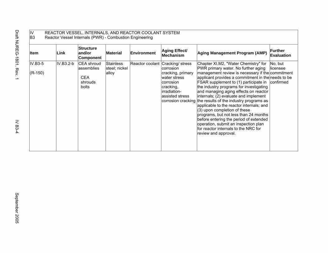
IV B3
REACTOR VESSEL, INTERNALS, AND REACTOR COOLANT SYSTEM Reactor Vessel Internals (PWR) - Combustion Engineering
Item Link Structure and/or Component
Material Environment Aging Effect/ Mechanism Aging Management Program (AMP) Further
Evaluation
IV.B3-5
(R-150)
IV.B3.2-b CEA shroud assemblies
CEA shrouds bolts
Stainless steel; nickel alloy
Reactor coolant Cracking/ stress corrosion cracking, primary water stress corrosion cracking, irradiation-assisted stress corrosion cracking
Chapter XI.M2, "Water Chemistry" for PWR primary water. No further aging management review is necessary if the applicant provides a commitment in the FSAR supplement to (1) participate in the industry programs for investigating and managing aging effects on reactor internals; (2) evaluate and implement the results of the industry programs as applicable to the reactor internals; and (3) upon completion of these programs, but not less than 24 months before entering the period of extended operation, submit an inspection plan for reactor internals to the NRC for review and approval.
No, but licensee commitment needs to be confirmed
Draft N
UR
EG
-1801, Rev. 1
IV B
3-4 S
eptember 2005
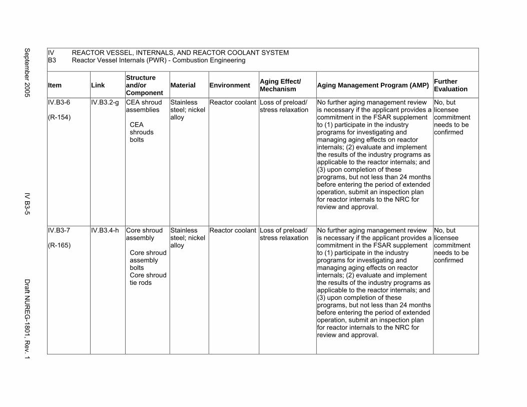
IV REACTOR VESSEL, INTERNALS, AND REACTOR COOLANT SYSTEM B3 Reactor Vessel Internals (PWR) - Combustion Engineering
Item Link Structure and/or Component
Material Environment Aging Effect/ Mechanism Aging Management Program (AMP) Further
Evaluation
IV.B3-6
(R-154)
IV.B3.2-g CEA shroud assemblies
CEA shrouds bolts
Stainless steel; nickel alloy
Reactor coolant Loss of preload/ stress relaxation
No further aging management review is necessary if the applicant provides a commitment in the FSAR supplement to (1) participate in the industry programs for investigating and managing aging effects on reactor internals; (2) evaluate and implement the results of the industry programs as applicable to the reactor internals; and (3) upon completion of these programs, but not less than 24 months before entering the period of extended operation, submit an inspection plan for reactor internals to the NRC for review and approval.
No, but licensee commitment needs to be confirmed
IV.B3-7
(R-165)
IV.B3.4-h Core shroud assembly
Core shroud assembly bolts Core shroud tie rods
Stainless steel; nickel alloy
Reactor coolant Loss of preload/ stress relaxation
No further aging management review is necessary if the applicant provides a commitment in the FSAR supplement to (1) participate in the industry programs for investigating and managing aging effects on reactor internals; (2) evaluate and implement the results of the industry programs as applicable to the reactor internals; and (3) upon completion of these programs, but not less than 24 months before entering the period of extended operation, submit an inspection plan for reactor internals to the NRC for review and approval.
No, but licensee commitment needs to be confirmed
Septem
ber 2005 IV
B3-5
Draft N
UR
EG
-1801, Rev. 1
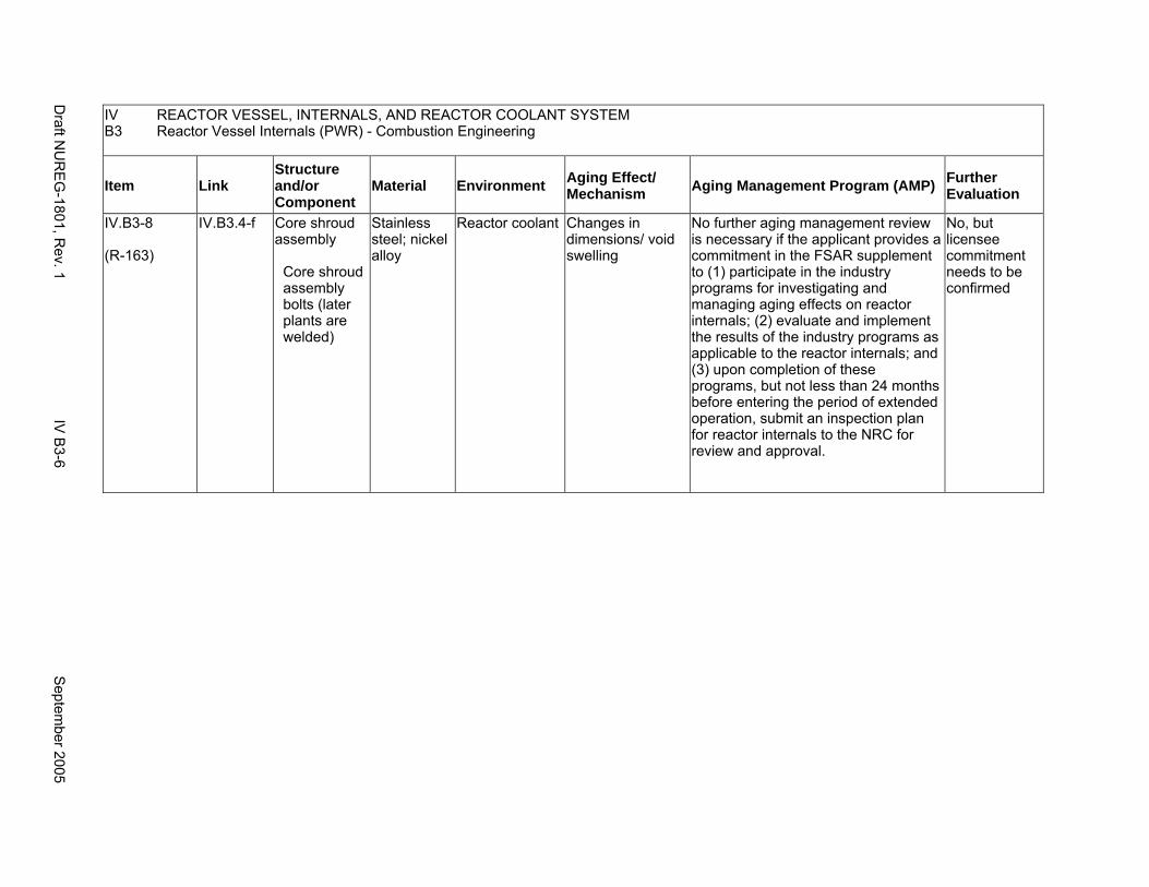
IV REACTOR VESSEL, INTERNALS, AND REACTOR COOLANT SYSTEM B3 Reactor Vessel Internals (PWR) - Combustion Engineering
Item Link Structure and/or Component
Material Environment Aging Effect/ Mechanism Aging Management Program (AMP) Further
Evaluation
IV.B3-8
(R-163)
IV.B3.4-f Core shroud assembly
Core shroud assembly bolts (later plants are welded)
Stainless steel; nickel alloy
Reactor coolant Changes in dimensions/ void swelling
No further aging management review is necessary if the applicant provides a commitment in the FSAR supplement to (1) participate in the industry programs for investigating and managing aging effects on reactor internals; (2) evaluate and implement the results of the industry programs as applicable to the reactor internals; and (3) upon completion of these programs, but not less than 24 months before entering the period of extended operation, submit an inspection plan for reactor internals to the NRC for review and approval.
No, but licensee commitment needs to be confirmed
Draft N
UR
EG
-1801, Rev. 1
IV B
3-6 S
eptember 2005

IV B3
REACTOR VESSEL, INTERNALS, AND REACTOR COOLANT SYSTEM Reactor Vessel Internals (PWR) - Combustion Engineering
Item Link Structure and/or Component
Material Environment Aging Effect/ Mechanism Aging Management Program (AMP) Further
Evaluation
IV.B3-9
(R-162)
IV.B3.4-e Core shroud assembly
Core shroud assembly bolts (later plants are welded)
Stainless steel; nickel alloy
Reactor coolant Cracking/ stress corrosion cracking, primary water stress corrosion cracking, irradiation-assisted stress corrosion cracking
Chapter XI.M2, "Water Chemistry" for PWR primary water
No further aging management review is necessary if the applicant provides a commitment in the FSAR supplement to (1) participate in the industry programs for investigating and managing aging effects on reactor internals; (2) evaluate and implement the results of the industry programs as applicable to the reactor internals; and (3) upon completion of these programs, but not less than 24 months before entering the period of extended operation, submit an inspection plan for reactor internals to the NRC for review and approval.
No, but licensee commitment needs to be confirmed
Septem
ber 2005 IV
B3-7
Draft N
UR
EG
-1801, Rev. 1
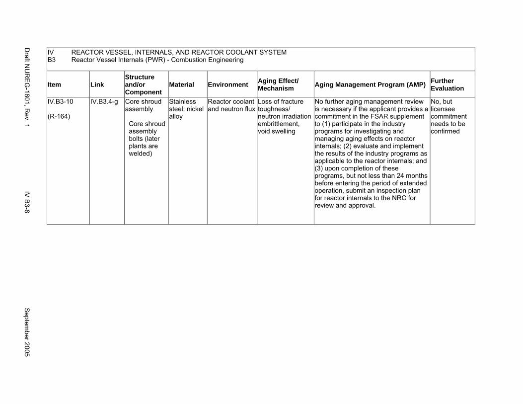
IV REACTOR VESSEL, INTERNALS, AND REACTOR COOLANT SYSTEM B3 Reactor Vessel Internals (PWR) - Combustion Engineering
Item Link Structure and/or Component
Material Environment Aging Effect/ Mechanism Aging Management Program (AMP) Further
Evaluation
IV.B3-10
(R-164)
IV.B3.4-g Core shroud assembly
Core shroud assembly bolts (later plants are welded)
Stainless steel; nickel alloy
Reactor coolant and neutron flux
Loss of fracture toughness/ neutron irradiation embrittlement, void swelling
No further aging management review is necessary if the applicant provides a commitment in the FSAR supplement to (1) participate in the industry programs for investigating and managing aging effects on reactor internals; (2) evaluate and implement the results of the industry programs as applicable to the reactor internals; and (3) upon completion of these programs, but not less than 24 months before entering the period of extended operation, submit an inspection plan for reactor internals to the NRC for review and approval.
No, but licensee commitment needs to be confirmed
Draft N
UR
EG
-1801, Rev. 1
IV B
3-8 S
eptember 2005

IV REACTOR VESSEL, INTERNALS, AND REACTOR COOLANT SYSTEM B3 Reactor Vessel Internals (PWR) - Combustion Engineering
Item Link Structure and/or Component
Material Environment Aging Effect/ Mechanism Aging Management Program (AMP) Further
Evaluation
IV.B3-11
(R-159)
IV.B3.4-a Core shroud assembly
Core shroud tie rods (core support plate attached by welds in later plants)
Stainless steel
Reactor coolant Cracking/ stress corrosion cracking, irradiation-assisted stress corrosion cracking
Chapter XI.M2, "Water Chemistry" for PWR primary water
No further aging management review is necessary if the applicant provides a commitment in the FSAR supplement to (1) participate in the industry programs for investigating and managing aging effects on reactor internals; (2) evaluate and implement the results of the industry programs as applicable to the reactor internals; and (3) upon completion of these programs, but not less than 24 months before entering the period of extended operation, submit an inspection plan for reactor internals to the NRC for review and approval.
No, but licensee commitment needs to be confirmed
Septem
ber 2005 IV
B3-9
Draft N
UR
EG
-1801, Rev. 1
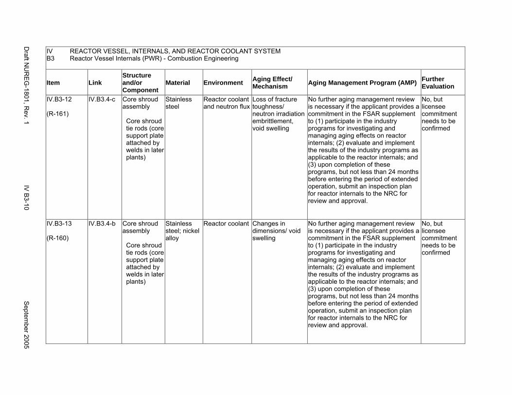
IV REACTOR VESSEL, INTERNALS, AND REACTOR COOLANT SYSTEM B3 Reactor Vessel Internals (PWR) - Combustion Engineering
Item Link Structure and/or Component
Material Environment Aging Effect/ Mechanism Aging Management Program (AMP) Further
Evaluation
IV.B3-12
(R-161)
IV.B3.4-c Core shroud assembly
Core shroud tie rods (core support plate attached by welds in later plants)
Stainless steel
Reactor coolant and neutron flux
Loss of fracture toughness/ neutron irradiation embrittlement, void swelling
No further aging management review is necessary if the applicant provides a commitment in the FSAR supplement to (1) participate in the industry programs for investigating and managing aging effects on reactor internals; (2) evaluate and implement the results of the industry programs as applicable to the reactor internals; and (3) upon completion of these programs, but not less than 24 months before entering the period of extended operation, submit an inspection plan for reactor internals to the NRC for review and approval.
No, but licensee commitment needs to be confirmed
IV.B3-13
(R-160)
IV.B3.4-b Core shroud assembly
Core shroud tie rods (core support plate attached by welds in later plants)
Stainless steel; nickel alloy
Reactor coolant Changes in dimensions/ void swelling
No further aging management review is necessary if the applicant provides a commitment in the FSAR supplement to (1) participate in the industry programs for investigating and managing aging effects on reactor internals; (2) evaluate and implement the results of the industry programs as applicable to the reactor internals; and (3) upon completion of these programs, but not less than 24 months before entering the period of extended operation, submit an inspection plan for reactor internals to the NRC for review and approval.
No, but licensee commitment needs to be confirmed
Draft N
UR
EG
-1801, Rev. 1
IV B
3-10 S
eptember 2005
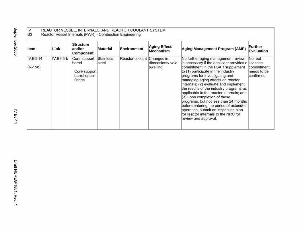
IV REACTOR VESSEL, INTERNALS, AND REACTOR COOLANT SYSTEM B3 Reactor Vessel Internals (PWR) - Combustion Engineering
Item Link Structure and/or Component
Material Environment Aging Effect/ Mechanism Aging Management Program (AMP) Further
Evaluation
IV.B3-14
(R-158)
IV.B3.3-b Core support barrel
Core support barrel upper flange
Stainless steel
Reactor coolant Changes in dimensions/ void swelling
No further aging management review is necessary if the applicant provides a commitment in the FSAR supplement to (1) participate in the industry programs for investigating and managing aging effects on reactor internals; (2) evaluate and implement the results of the industry programs as applicable to the reactor internals; and (3) upon completion of these programs, but not less than 24 months before entering the period of extended operation, submit an inspection plan for reactor internals to the NRC for review and approval.
No, but licensee commitment needs to be confirmed
Septem
ber 2005 IV
B3-11
Draft N
UR
EG
-1801, Rev. 1
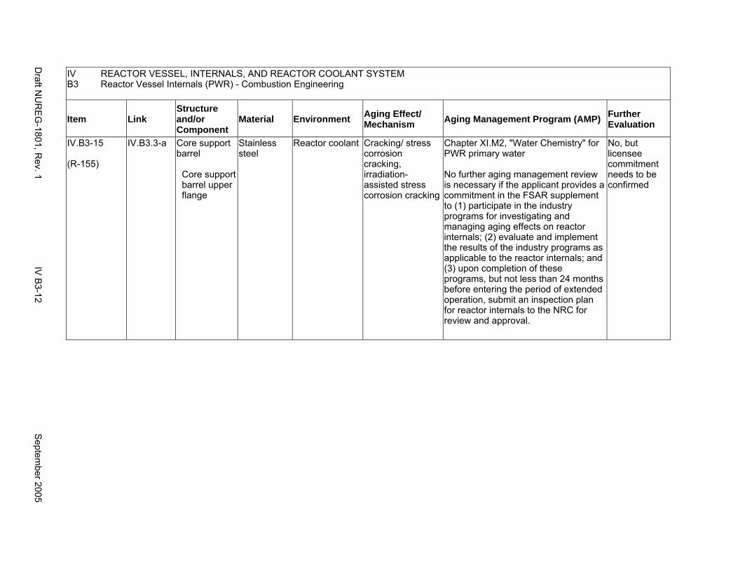
IV REACTOR VESSEL, INTERNALS, AND REACTOR COOLANT SYSTEM B3 Reactor Vessel Internals (PWR) - Combustion Engineering
Item Link Structure and/or Component
Material Environment Aging Effect/ Mechanism Aging Management Program (AMP) Further
Evaluation
IV.B3-15
(R-155)
IV.B3.3-a Core support barrel
Core support barrel upper flange
Stainless steel
Reactor coolant Cracking/ stress corrosion cracking, irradiation-assisted stress corrosion cracking
Chapter XI.M2, "Water Chemistry" for PWR primary water
No further aging management review is necessary if the applicant provides a commitment in the FSAR supplement to (1) participate in the industry programs for investigating and managing aging effects on reactor internals; (2) evaluate and implement the results of the industry programs as applicable to the reactor internals; and (3) upon completion of these programs, but not less than 24 months before entering the period of extended operation, submit an inspection plan for reactor internals to the NRC for review and approval.
No, but licensee commitment needs to be confirmed
Draft N
UR
EG
-1801, Rev. 1
IV B
3-12 S
eptember 2005
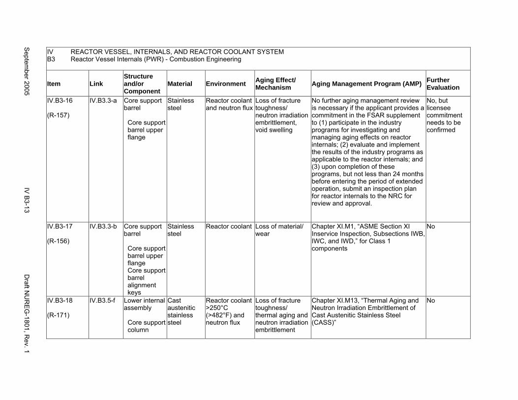
IV REACTOR VESSEL, INTERNALS, AND REACTOR COOLANT SYSTEM B3 Reactor Vessel Internals (PWR) - Combustion Engineering
Item Link Structure and/or Component
Material Environment Aging Effect/ Mechanism Aging Management Program (AMP) Further
Evaluation
IV.B3-16
(R-157)
IV.B3.3-a Core support barrel
Core support barrel upper flange
Stainless steel
Reactor coolant and neutron flux
Loss of fracture toughness/ neutron irradiation embrittlement, void swelling
No further aging management review is necessary if the applicant provides a commitment in the FSAR supplement to (1) participate in the industry programs for investigating and managing aging effects on reactor internals; (2) evaluate and implement the results of the industry programs as applicable to the reactor internals; and (3) upon completion of these programs, but not less than 24 months before entering the period of extended operation, submit an inspection plan for reactor internals to the NRC for review and approval.
No, but licensee commitment needs to be confirmed
IV.B3-17
(R-156)
IV.B3.3-b Core support barrel
Core support barrel upper flange Core support barrel alignment keys
Stainless steel
Reactor coolant Loss of material/ wear
Chapter XI.M1, “ASME Section XI Inservice Inspection, Subsections IWB, IWC, and IWD,” for Class 1 components
No
IV.B3-18
(R-171)
IV.B3.5-f Lower internal assembly
Core support column
Cast austenitic stainless steel
Reactor coolant >250°C (>482°F) and neutron flux
Loss of fracture toughness/ thermal aging and neutron irradiation embrittlement
Chapter XI.M13, “Thermal Aging and Neutron Irradiation Embrittlement of Cast Austenitic Stainless Steel (CASS)”
No
Septem
ber 2005 IV
B3-13
Draft N
UR
EG
-1801, Rev. 1
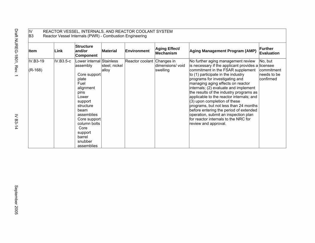
IV REACTOR VESSEL, INTERNALS, AND REACTOR COOLANT SYSTEM B3 Reactor Vessel Internals (PWR) - Combustion Engineering
Item Link Structure and/or Component
Material Environment Aging Effect/ Mechanism Aging Management Program (AMP) Further
Evaluation
IV.B3-19
(R-168)
IV.B3.5-c Lower internal assembly
Core support plate Fuel alignment pins Lower support structure beam assemblies Core support column bolts Core support barrel snubber assemblies
Stainless steel; nickel alloy
Reactor coolant Changes in dimensions/ void swelling
No further aging management review is necessary if the applicant provides a commitment in the FSAR supplement to (1) participate in the industry programs for investigating and managing aging effects on reactor internals; (2) evaluate and implement the results of the industry programs as applicable to the reactor internals; and (3) upon completion of these programs, but not less than 24 months before entering the period of extended operation, submit an inspection plan for reactor internals to the NRC for review and approval.
No, but licensee commitment needs to be confirmed
Draft N
UR
EG
-1801, Rev. 1
IV B
3-14 S
eptember 2005
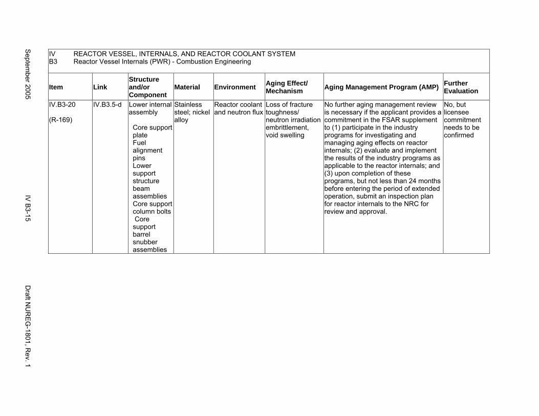
IV REACTOR VESSEL, INTERNALS, AND REACTOR COOLANT SYSTEM B3 Reactor Vessel Internals (PWR) - Combustion Engineering
Item Link Structure and/or Component
Material Environment Aging Effect/ Mechanism Aging Management Program (AMP) Further
Evaluation
IV.B3-20
(R-169)
IV.B3.5-d Lower internal assembly
Core support plate Fuel alignment pins Lower support structure beam assemblies Core support column bolts Core support barrel snubber assemblies
Stainless steel; nickel alloy
Reactor coolant and neutron flux
Loss of fracture toughness/ neutron irradiation embrittlement, void swelling
No further aging management review is necessary if the applicant provides a commitment in the FSAR supplement to (1) participate in the industry programs for investigating and managing aging effects on reactor internals; (2) evaluate and implement the results of the industry programs as applicable to the reactor internals; and (3) upon completion of these programs, but not less than 24 months before entering the period of extended operation, submit an inspection plan for reactor internals to the NRC for review and approval.
No, but licensee commitment needs to be confirmed
Septem
ber 2005 IV
B3-15
Draft N
UR
EG
-1801, Rev. 1
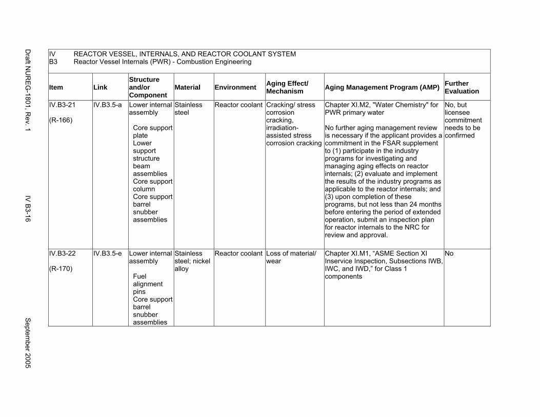
IV REACTOR VESSEL, INTERNALS, AND REACTOR COOLANT SYSTEM B3 Reactor Vessel Internals (PWR) - Combustion Engineering
Item Link Structure and/or Component
Material Environment Aging Effect/ Mechanism Aging Management Program (AMP) Further
Evaluation
IV.B3-21
(R-166)
IV.B3.5-a Lower internal assembly
Core support plate Lower support structure beam assemblies Core support column Core support barrel snubber assemblies
Stainless steel
Reactor coolant Cracking/ stress corrosion cracking, irradiation-assisted stress corrosion cracking
Chapter XI.M2, "Water Chemistry" for PWR primary water
No further aging management review is necessary if the applicant provides a commitment in the FSAR supplement to (1) participate in the industry programs for investigating and managing aging effects on reactor internals; (2) evaluate and implement the results of the industry programs as applicable to the reactor internals; and (3) upon completion of these programs, but not less than 24 months before entering the period of extended operation, submit an inspection plan for reactor internals to the NRC for review and approval.
No, but licensee commitment needs to be confirmed
IV.B3-22
(R-170)
IV.B3.5-e Lower internal assembly
Fuel alignment pins Core support barrel snubber assemblies
Stainless steel; nickel alloy
Reactor coolant Loss of material/ wear
Chapter XI.M1, “ASME Section XI Inservice Inspection, Subsections IWB, IWC, and IWD,” for Class 1 components
No
Draft N
UR
EG
-1801, Rev. 1
IV B
3-16 S
eptember 2005
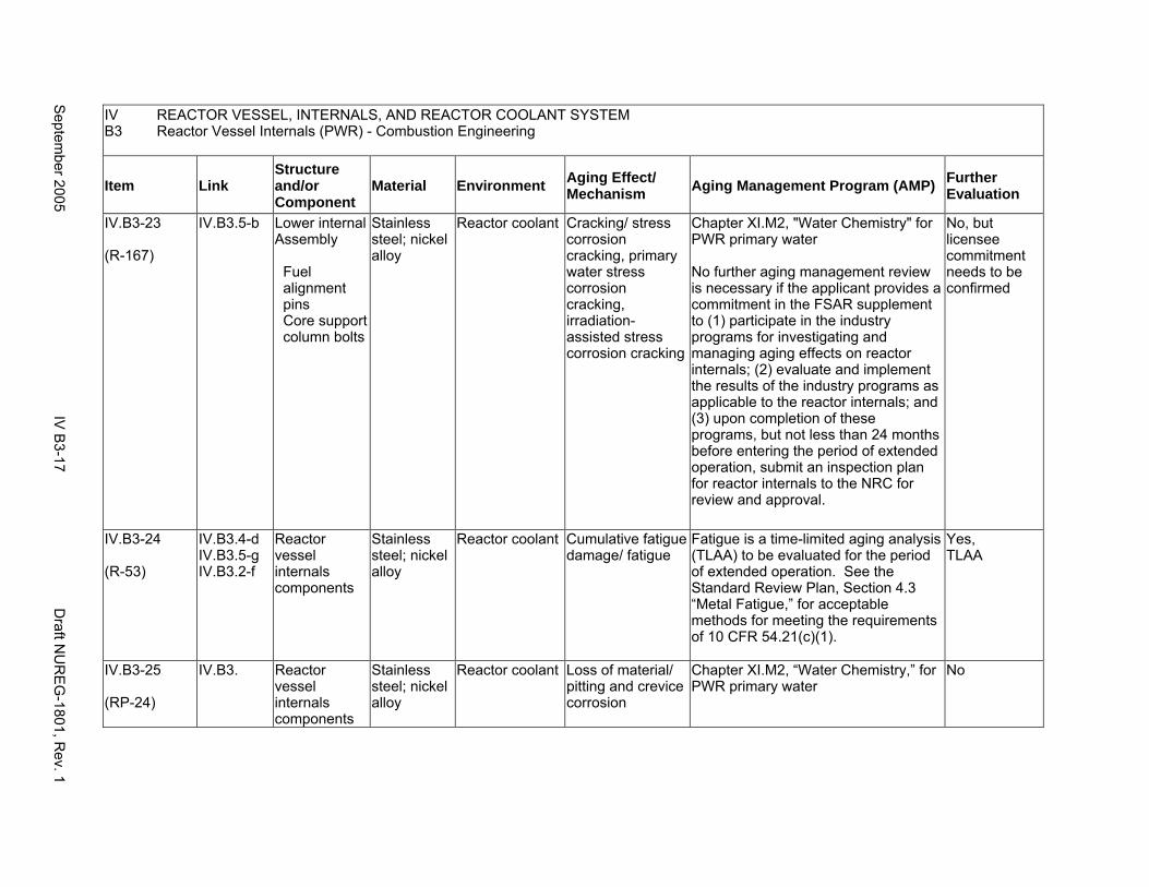
IV REACTOR VESSEL, INTERNALS, AND REACTOR COOLANT SYSTEM B3 Reactor Vessel Internals (PWR) - Combustion Engineering
Item Link Structure and/or Component
Material Environment Aging Effect/ Mechanism Aging Management Program (AMP) Further
Evaluation
IV.B3-23
(R-167)
IV.B3.5-b Lower internal Assembly
Fuel alignment pins Core support column bolts
Stainless steel; nickel alloy
Reactor coolant Cracking/ stress corrosion cracking, primary water stress corrosion cracking, irradiation-assisted stress corrosion cracking
Chapter XI.M2, "Water Chemistry" for PWR primary water
No further aging management review is necessary if the applicant provides a commitment in the FSAR supplement to (1) participate in the industry programs for investigating and managing aging effects on reactor internals; (2) evaluate and implement the results of the industry programs as applicable to the reactor internals; and (3) upon completion of these programs, but not less than 24 months before entering the period of extended operation, submit an inspection plan for reactor internals to the NRC for review and approval.
No, but licensee commitment needs to be confirmed
IV.B3-24
(R-53)
IV.B3.4-d IV.B3.5-g IV.B3.2-f
Reactor vessel internals components
Stainless steel; nickel alloy
Reactor coolant Cumulative fatigue damage/ fatigue
Fatigue is a time-limited aging analysis (TLAA) to be evaluated for the period of extended operation. See the Standard Review Plan, Section 4.3 “Metal Fatigue,” for acceptable methods for meeting the requirements of 10 CFR 54.21(c)(1).
Yes, TLAA
IV.B3-25
(RP-24)
IV.B3. Reactor vessel internals components
Stainless steel; nickel alloy
Reactor coolant Loss of material/ pitting and crevice corrosion
Chapter XI.M2, “Water Chemistry,” for PWR primary water
No
Septem
ber 2005 IV
B3-17
Draft N
UR
EG
-1801, Rev. 1
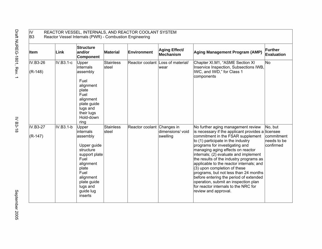
IV REACTOR VESSEL, INTERNALS, AND REACTOR COOLANT SYSTEM B3 Reactor Vessel Internals (PWR) - Combustion Engineering
Item Link Structure and/or Component
Material Environment Aging Effect/ Mechanism Aging Management Program (AMP) Further
Evaluation
IV.B3-26
(R-148)
IV.B3.1-c Upper internals assembly
Fuel alignment plate Fuel alignment plate guide lugs and their lugs Hold-down ring
Stainless steel
Reactor coolant Loss of material/ wear
Chapter XI.M1, “ASME Section XI Inservice Inspection, Subsections IWB, IWC, and IWD,” for Class 1 components
No
IV.B3-27
(R-147)
IV.B3.1-b Upper internals assembly
Upper guide structure support plate Fuel alignment plate Fuel alignment plate guide lugs and guide lug inserts
Stainless steel
Reactor coolant Changes in dimensions/ void swelling
No further aging management review is necessary if the applicant provides a commitment in the FSAR supplement to (1) participate in the industry programs for investigating and managing aging effects on reactor internals; (2) evaluate and implement the results of the industry programs as applicable to the reactor internals; and (3) upon completion of these programs, but not less than 24 months before entering the period of extended operation, submit an inspection plan for reactor internals to the NRC for review and approval.
No, but licensee commitment needs to be confirmed
Draft N
UR
EG
-1801, Rev. 1
IV B
3-18 S
eptember 2005
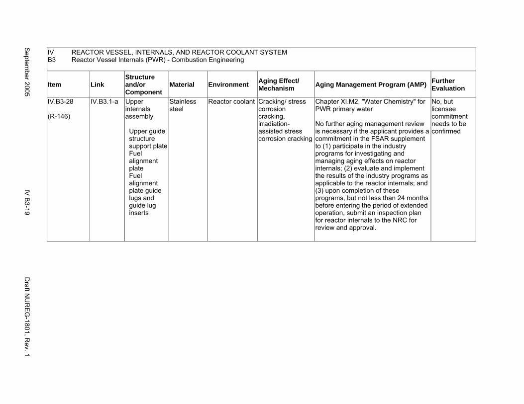
IV REACTOR VESSEL, INTERNALS, AND REACTOR COOLANT SYSTEM B3 Reactor Vessel Internals (PWR) - Combustion Engineering
Item Link Structure and/or Component
Material Environment Aging Effect/ Mechanism Aging Management Program (AMP) Further
Evaluation
IV.B3-28
(R-146)
IV.B3.1-a Upper internals assembly
Upper guide structure support plate Fuel alignment plate Fuel alignment plate guide lugs and guide lug inserts
Stainless steel
Reactor coolant Cracking/ stress corrosion cracking, irradiation-assisted stress corrosion cracking
Chapter XI.M2, "Water Chemistry" for PWR primary water
No further aging management review is necessary if the applicant provides a commitment in the FSAR supplement to (1) participate in the industry programs for investigating and managing aging effects on reactor internals; (2) evaluate and implement the results of the industry programs as applicable to the reactor internals; and (3) upon completion of these programs, but not less than 24 months before entering the period of extended operation, submit an inspection plan for reactor internals to the NRC for review and approval.
No, but licensee commitment needs to be confirmed
Septem
ber 2005 IV
B3-19
Draft N
UR
EG
-1801, Rev. 1
This Page Intentionally Left Blank
Draft NUREG-1801, Rev. 1 IV.B3-20 September 2005
B4. REACTOR VESSEL INTERNALS (PWR) - BABCOCK AND WILCOX
Systems, Structures, and Components
This section addresses the Babcock and Wilcox pressurized water reactor (PWR) vessel internals and consists of the plenum cover and plenum cylinder, the upper grid assembly, the control rod guide tube (CRGT) assembly, the core support shield assembly, the core barrel assembly, the lower grid assembly, and the flow distributor assembly. Based on Regulatory Guide 1.26, “Quality Group Classifications and Standards for Water-, Steam-, and Radioactive-Waste-Containing Components of Nuclear Power Plants,” all structures and components that comprise the reactor vessel are governed by Group A or B Quality Standards.
Common miscellaneous material/environment combinations where aging effects are not expected to degrade the ability of the structure or component to perform its intended function for the extended period of operation are included in IV.E.
System Interfaces
The systems that interface with the reactor vessel internals include the reactor pressure vessel (IV.A2).
September 2005 IV B4-1 Draft NUREG-1801, Rev. 1
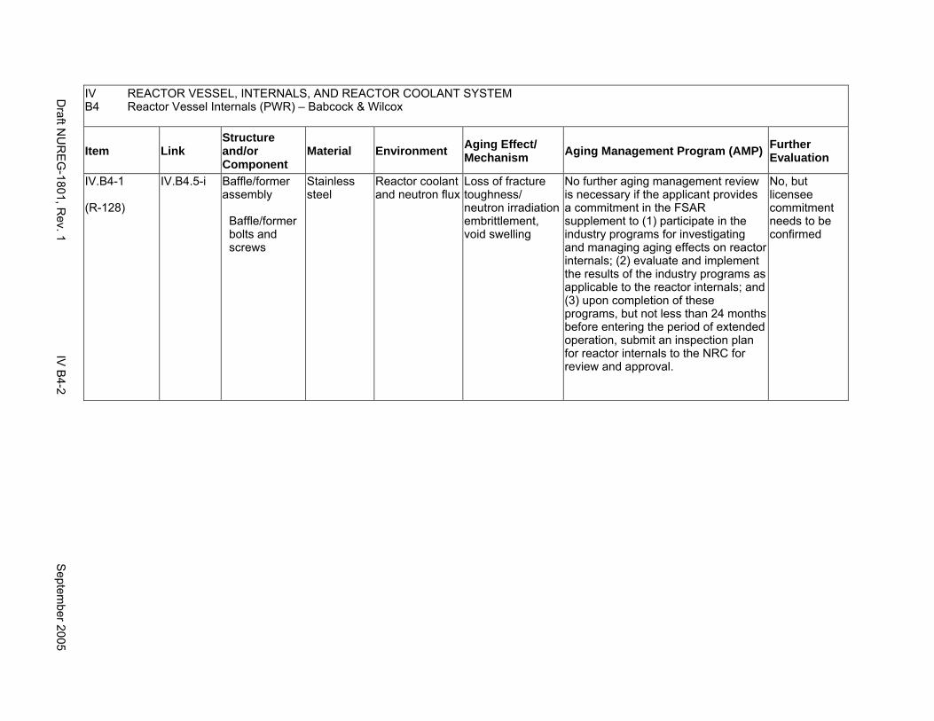
IV B4
REACTOR VESSEL, INTERNALS, AND REACTOR COOLANT SYSTEM Reactor Vessel Internals (PWR) – Babcock & Wilcox
Item Link Structure and/or Component
Material Environment Aging Effect/ Mechanism Aging Management Program (AMP) Further
Evaluation
IV.B4-1
(R-128)
IV.B4.5-i Baffle/former assembly
Baffle/former bolts and screws
Stainless steel
Reactor coolant and neutron flux
Loss of fracture toughness/ neutron irradiation embrittlement, void swelling
No further aging management review is necessary if the applicant provides a commitment in the FSAR supplement to (1) participate in the industry programs for investigating and managing aging effects on reactor internals; (2) evaluate and implement the results of the industry programs as applicable to the reactor internals; and (3) upon completion of these programs, but not less than 24 months before entering the period of extended operation, submit an inspection plan for reactor internals to the NRC for review and approval.
No, but licensee commitment needs to be confirmed
Draft N
UR
EG
-1801, Rev. 1
IV B
4-2 S
eptember 2005
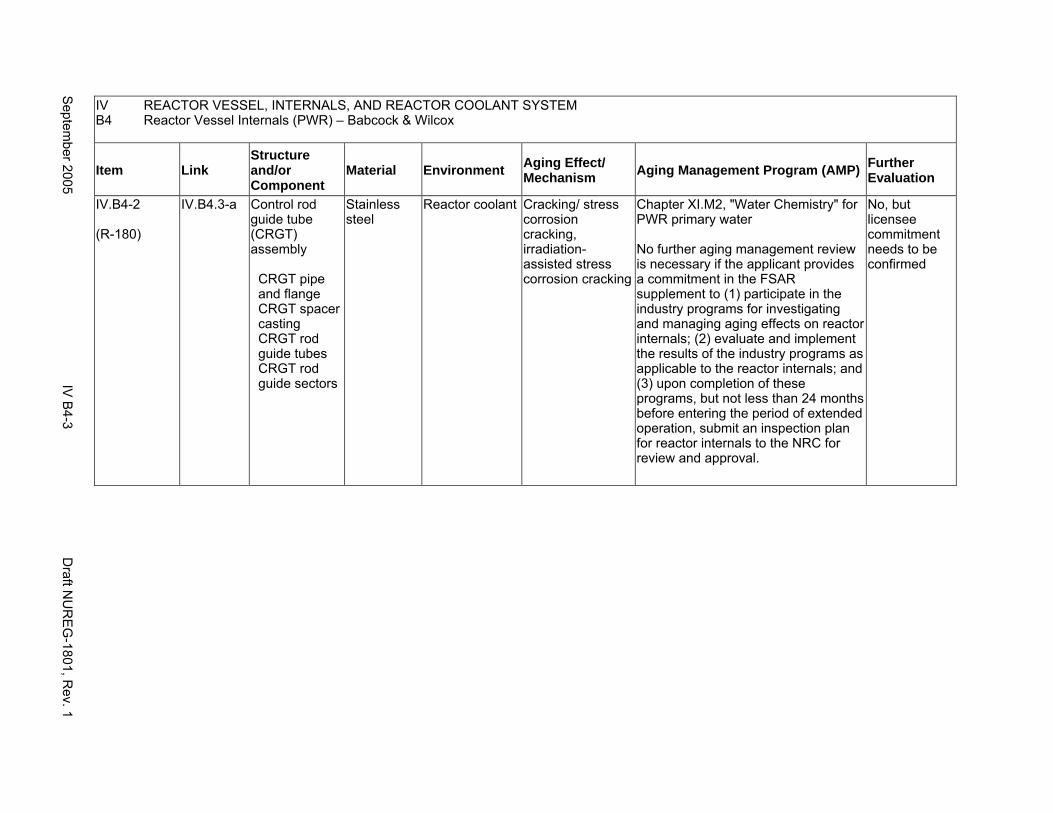
IV B4
REACTOR VESSEL, INTERNALS, AND REACTOR COOLANT SYSTEM Reactor Vessel Internals (PWR) – Babcock & Wilcox
Item Link Structure and/or Component
Material Environment Aging Effect/ Mechanism Aging Management Program (AMP) Further
Evaluation
IV.B4-2
(R-180)
IV.B4.3-a Control rod guide tube (CRGT) assembly
CRGT pipe and flange CRGT spacer casting CRGT rod guide tubes CRGT rod guide sectors
Stainless steel
Reactor coolant Cracking/ stress corrosion cracking, irradiation-assisted stress corrosion cracking
Chapter XI.M2, "Water Chemistry" for PWR primary water
No further aging management review is necessary if the applicant provides a commitment in the FSAR supplement to (1) participate in the industry programs for investigating and managing aging effects on reactor internals; (2) evaluate and implement the results of the industry programs as applicable to the reactor internals; and (3) upon completion of these programs, but not less than 24 months before entering the period of extended operation, submit an inspection plan for reactor internals to the NRC for review and approval.
No, but licensee commitment needs to be confirmed
Septem
ber 2005 IV
B4-3
Draft N
UR
EG
-1801, Rev. 1
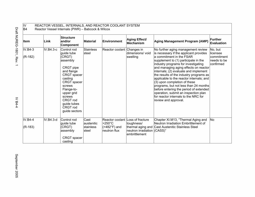
IV B4
REACTOR VESSEL, INTERNALS, AND REACTOR COOLANT SYSTEM Reactor Vessel Internals (PWR) – Babcock & Wilcox
Item Link Structure and/or Component
Material Environment Aging Effect/ Mechanism Aging Management Program (AMP) Further
Evaluation
IV.B4-3
(R-182)
IV.B4.3-c Control rod guide tube (CRGT) assembly
CRGT pipe and flange CRGT spacer casting CRGT spacer screws Flange-toupper grid screws CRGT rod guide tubes CRGT rod guide sectors
Stainless steel
Reactor coolant Changes in dimensions/ void swelling
No further aging management review is necessary if the applicant provides a commitment in the FSAR supplement to (1) participate in the industry programs for investigating and managing aging effects on reactor internals; (2) evaluate and implement the results of the industry programs as applicable to the reactor internals; and (3) upon completion of these programs, but not less than 24 months before entering the period of extended operation, submit an inspection plan for reactor internals to the NRC for review and approval.
No, but licensee commitment needs to be confirmed
IV.B4-4
(R-183)
IV.B4.3-d Control rod guide tube (CRGT) assembly
CRGT spacer casting
Cast austenitic stainless steel
Reactor coolant >250°C (>482°F) and neutron flux
Loss of fracture toughness/ thermal aging and neutron irradiation embrittlement
Chapter XI.M13, “Thermal Aging and Neutron Irradiation Embrittlement of Cast Austenitic Stainless Steel (CASS)”
No
Draft N
UR
EG
-1801, Rev. 1
IV B
4-4 S
eptember 2005

IV B4
REACTOR VESSEL, INTERNALS, AND REACTOR COOLANT SYSTEM Reactor Vessel Internals (PWR) – Babcock & Wilcox
Item Link Structure and/or Component
Material Environment Aging Effect/ Mechanism Aging Management Program (AMP) Further
Evaluation
IV.B4-5
(R-181)
IV.B4.3-b Control rod guide tube (CRGT) assembly
CRGT spacer screws Flange-toupper grid screws
Stainless steel
Reactor coolant Cracking/ stress corrosion cracking, irradiation-assisted stress corrosion cracking
Chapter XI.M2, "Water Chemistry" for PWR primary water
No further aging management review is necessary if the applicant provides a commitment in the FSAR supplement to (1) participate in the industry programs for investigating and managing aging effects on reactor internals; (2) evaluate and implement the results of the industry programs as applicable to the reactor internals; and (3) upon completion of these programs, but not less than 24 months before entering the period of extended operation, submit an inspection plan for reactor internals to the NRC for review and approval.
No, but licensee commitment needs to be confirmed
Septem
ber 2005 IV
B4-5
Draft N
UR
EG
-1801, Rev. 1
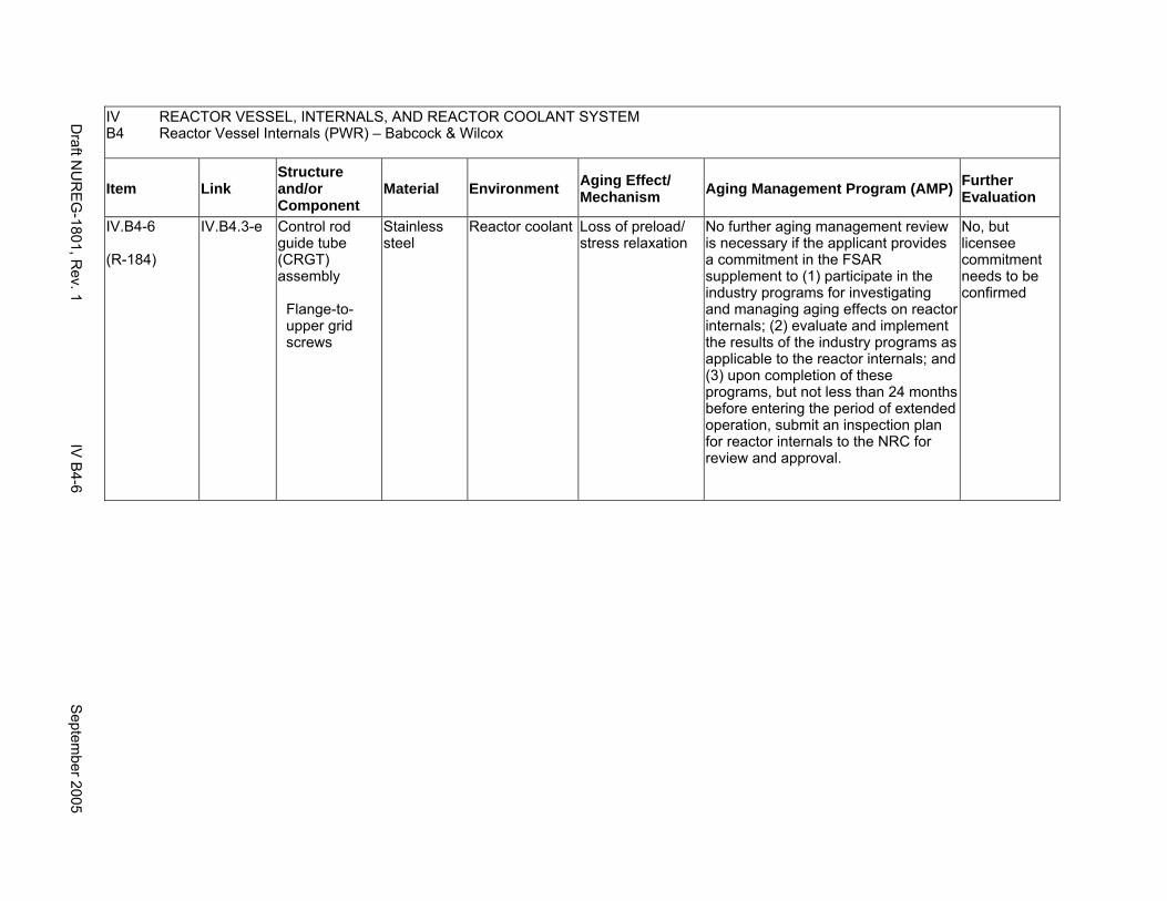
IV REACTOR VESSEL, INTERNALS, AND REACTOR COOLANT SYSTEM B4 Reactor Vessel Internals (PWR) – Babcock & Wilcox
Item Link Structure and/or Component
Material Environment Aging Effect/ Mechanism Aging Management Program (AMP) Further
Evaluation
IV.B4-6
(R-184)
IV.B4.3-e Control rod guide tube (CRGT) assembly
Flange-toupper grid screws
Stainless steel
Reactor coolant Loss of preload/ stress relaxation
No further aging management review is necessary if the applicant provides a commitment in the FSAR supplement to (1) participate in the industry programs for investigating and managing aging effects on reactor internals; (2) evaluate and implement the results of the industry programs as applicable to the reactor internals; and (3) upon completion of these programs, but not less than 24 months before entering the period of extended operation, submit an inspection plan for reactor internals to the NRC for review and approval.
No, but licensee commitment needs to be confirmed
Draft N
UR
EG
-1801, Rev. 1
IV B
4-6 S
eptember 2005

IV B4
REACTOR VESSEL, INTERNALS, AND REACTOR COOLANT SYSTEM Reactor Vessel Internals (PWR) – Babcock & Wilcox
Item Link Structure and/or Component
Material Environment Aging Effect/ Mechanism Aging Management Program (AMP) Further
Evaluation
IV.B4-7
(R-125)
IV.B4.5-g Core barrel assembly
Baffle/former assembly Baffle/former bolts and screws
Stainless steel
Reactor coolant Cracking/ stress corrosion cracking, irradiation-assisted stress corrosion cracking
Chapter XI.M2, "Water Chemistry," for PWR primary water
No further aging management review is necessary if the applicant provides a commitment in the FSAR supplement to (1) participate in the industry programs for investigating and managing aging effects on reactor internals; (2) evaluate and implement the results of the industry programs as applicable to the reactor internals; and (3) upon completion of these programs, but not less than 24 months before entering the period of extended operation, submit an inspection plan for reactor internals to the NRC for review and approval.
No, but licensee commitment needs to be confirmed
Septem
ber 2005 IV
B4-7
Draft N
UR
EG
-1801, Rev. 1
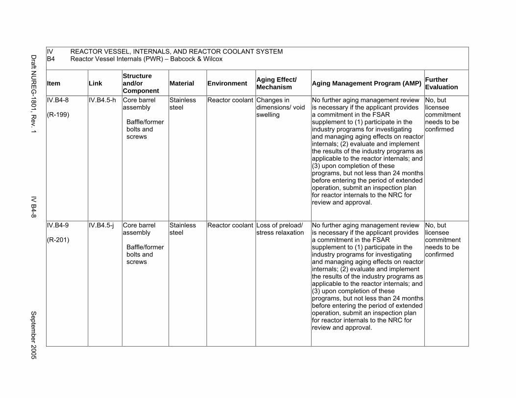
IV REACTOR VESSEL, INTERNALS, AND REACTOR COOLANT SYSTEM B4 Reactor Vessel Internals (PWR) – Babcock & Wilcox
Item Link Structure and/or Component
Material Environment Aging Effect/ Mechanism Aging Management Program (AMP) Further
Evaluation
IV.B4-8
(R-199)
IV.B4.5-h Core barrel assembly
Baffle/former bolts and screws
Stainless steel
Reactor coolant Changes in dimensions/ void swelling
No further aging management review is necessary if the applicant provides a commitment in the FSAR supplement to (1) participate in the industry programs for investigating and managing aging effects on reactor internals; (2) evaluate and implement the results of the industry programs as applicable to the reactor internals; and (3) upon completion of these programs, but not less than 24 months before entering the period of extended operation, submit an inspection plan for reactor internals to the NRC for review and approval.
No, but licensee commitment needs to be confirmed
IV.B4-9
(R-201)
IV.B4.5-j Core barrel assembly
Baffle/former bolts and screws
Stainless steel
Reactor coolant Loss of preload/ stress relaxation
No further aging management review is necessary if the applicant provides a commitment in the FSAR supplement to (1) participate in the industry programs for investigating and managing aging effects on reactor internals; (2) evaluate and implement the results of the industry programs as applicable to the reactor internals; and (3) upon completion of these programs, but not less than 24 months before entering the period of extended operation, submit an inspection plan for reactor internals to the NRC for review and approval.
No, but licensee commitment needs to be confirmed
Draft N
UR
EG
-1801, Rev. 1
IV B
4-8 S
eptember 2005

IV REACTOR VESSEL, INTERNALS, AND REACTOR COOLANT SYSTEM B4 Reactor Vessel Internals (PWR) – Babcock & Wilcox
Item Link Structure and/or Component
Material Environment Aging Effect/ Mechanism Aging Management Program (AMP) Further
Evaluation
IV.B4-10
(R-193)
IV.B4.5-a Core barrel assembly
Core barrel cylinder (top and bottom flange) Baffle plates and formers
Stainless steel
Reactor coolant Cracking/ stress corrosion cracking, irradiation-assisted stress corrosion cracking
Chapter XI.M2, "Water Chemistry" for PWR primary water
No further aging management review is necessary if the applicant provides a commitment in the FSAR supplement to (1) participate in the industry programs for investigating and managing aging effects on reactor internals; (2) evaluate and implement the results of the industry programs as applicable to the reactor internals; and (3) upon completion of these programs, but not less than 24 months before entering the period of extended operation, submit an inspection plan for reactor internals to the NRC for review and approval.
No, but licensee commitment needs to be confirmed
Septem
ber 2005 IV
B4-9
Draft N
UR
EG
-1801, Rev. 1
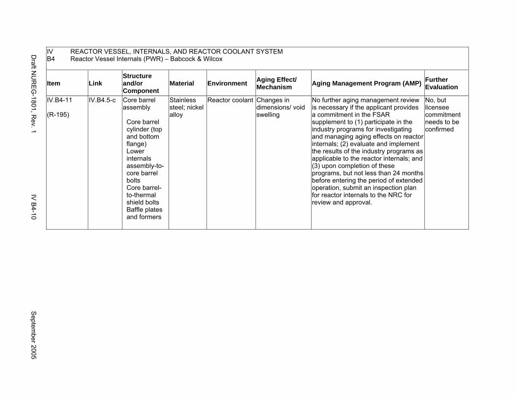
IV REACTOR VESSEL, INTERNALS, AND REACTOR COOLANT SYSTEM B4 Reactor Vessel Internals (PWR) – Babcock & Wilcox
Item Link Structure and/or Component
Material Environment Aging Effect/ Mechanism Aging Management Program (AMP) Further
Evaluation
IV.B4-11
(R-195)
IV.B4.5-c Core barrel assembly
Core barrel cylinder (top and bottom flange) Lower internals assembly-to- core barrel bolts Core barrel-to-thermal shield bolts Baffle plates and formers
Stainless steel; nickel alloy
Reactor coolant Changes in dimensions/ void swelling
No further aging management review is necessary if the applicant provides a commitment in the FSAR supplement to (1) participate in the industry programs for investigating and managing aging effects on reactor internals; (2) evaluate and implement the results of the industry programs as applicable to the reactor internals; and (3) upon completion of these programs, but not less than 24 months before entering the period of extended operation, submit an inspection plan for reactor internals to the NRC for review and approval.
No, but licensee commitment needs to be confirmed
Draft N
UR
EG
-1801, Rev. 1
IV B
4-10 S
eptember 2005
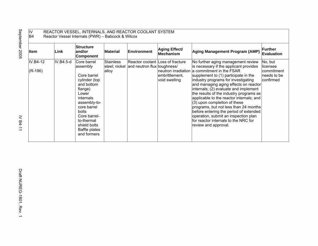
IV REACTOR VESSEL, INTERNALS, AND REACTOR COOLANT SYSTEM B4 Reactor Vessel Internals (PWR) – Babcock & Wilcox
Item Link Structure and/or Component
Material Environment Aging Effect/ Mechanism Aging Management Program (AMP) Further
Evaluation
IV.B4-12
(R-196)
IV.B4.5-d Core barrel assembly
Core barrel cylinder (top and bottom flange) Lower internals assembly-to- core barrel bolts Core barrel-to-thermal shield bolts Baffle plates and formers
Stainless steel; nickel alloy
Reactor coolant and neutron flux
Loss of fracture toughness/ neutron irradiation embrittlement, void swelling
No further aging management review is necessary if the applicant provides a commitment in the FSAR supplement to (1) participate in the industry programs for investigating and managing aging effects on reactor internals; (2) evaluate and implement the results of the industry programs as applicable to the reactor internals; and (3) upon completion of these programs, but not less than 24 months before entering the period of extended operation, submit an inspection plan for reactor internals to the NRC for review and approval.
No, but licensee commitment needs to be confirmed
Septem
ber 2005 IV
B4-11
Draft N
UR
EG
-1801, Rev. 1

IV REACTOR VESSEL, INTERNALS, AND REACTOR COOLANT SYSTEM B4 Reactor Vessel Internals (PWR) – Babcock & Wilcox
Item Link Structure and/or Component
Material Environment Aging Effect/ Mechanism Aging Management Program (AMP) Further
Evaluation
IV.B4-13
(R-194)
IV.B4.5-b Core barrel assembly
Lower internals assembly-tocore barrel bolts Core barrel-to-thermal shield bolts
Stainless steel; nickel alloy
Reactor coolant Cracking/ stress corrosion cracking, primary water stress corrosion cracking, irradiation-assisted stress corrosion cracking
Chapter XI.M2, "Water Chemistry" for PWR primary water
No further aging management review is necessary if the applicant provides a commitment in the FSAR supplement to (1) participate in the industry programs for investigating and managing aging effects on reactor internals; (2) evaluate and implement the results of the industry programs as applicable to the reactor internals; and (3) upon completion of these programs, but not less than 24 months before entering the period of extended operation, submit an inspection plan for reactor internals to the NRC for review and approval.
No, but licensee commitment needs to be confirmed
Draft N
UR
EG
-1801, Rev. 1
IV B
4-12 S
eptember 2005
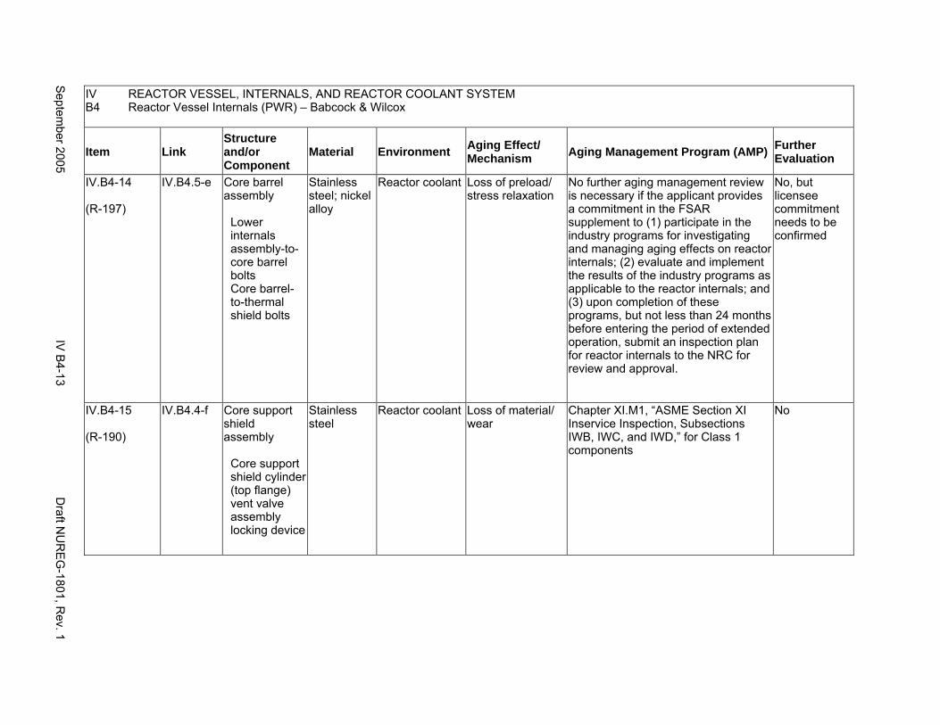
IV REACTOR VESSEL, INTERNALS, AND REACTOR COOLANT SYSTEM B4 Reactor Vessel Internals (PWR) – Babcock & Wilcox
Item Link Structure and/or Component
Material Environment Aging Effect/ Mechanism Aging Management Program (AMP) Further
Evaluation
IV.B4-14
(R-197)
IV.B4.5-e Core barrel assembly
Lower internals assembly-tocore barrel bolts Core barrel-to-thermal shield bolts
Stainless steel; nickel alloy
Reactor coolant Loss of preload/ stress relaxation
No further aging management review is necessary if the applicant provides a commitment in the FSAR supplement to (1) participate in the industry programs for investigating and managing aging effects on reactor internals; (2) evaluate and implement the results of the industry programs as applicable to the reactor internals; and (3) upon completion of these programs, but not less than 24 months before entering the period of extended operation, submit an inspection plan for reactor internals to the NRC for review and approval.
No, but licensee commitment needs to be confirmed
IV.B4-15
(R-190)
IV.B4.4-f Core support shield assembly
Core support shield cylinder (top flange) vent valve assembly locking device
Stainless steel
Reactor coolant Loss of material/ wear
Chapter XI.M1, “ASME Section XI Inservice Inspection, Subsections IWB, IWC, and IWD,” for Class 1 components
No
Septem
ber 2005 IV
B4-13
Draft N
UR
EG
-1801, Rev. 1
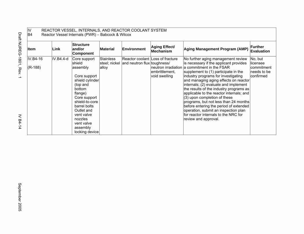
IV REACTOR VESSEL, INTERNALS, AND REACTOR COOLANT SYSTEM B4 Reactor Vessel Internals (PWR) – Babcock & Wilcox
Item Link Structure and/or Component
Material Environment Aging Effect/ Mechanism Aging Management Program (AMP) Further
Evaluation
IV.B4-16
(R-188)
IV.B4.4-d Core support shield assembly
Core support shield cylinder (top and bottom flange) Core support shield-to-core barrel bolts Outlet and vent valve nozzles vent valve assembly locking device
Stainless steel; nickel alloy
Reactor coolant and neutron flux
Loss of fracture toughness/ neutron irradiation embrittlement, void swelling
No further aging management review is necessary if the applicant provides a commitment in the FSAR supplement to (1) participate in the industry programs for investigating and managing aging effects on reactor internals; (2) evaluate and implement the results of the industry programs as applicable to the reactor internals; and (3) upon completion of these programs, but not less than 24 months before entering the period of extended operation, submit an inspection plan for reactor internals to the NRC for review and approval.
No, but licensee commitment needs to be confirmed
Draft N
UR
EG
-1801, Rev. 1
IV B
4-14 S
eptember 2005
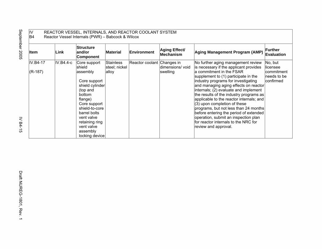
IV REACTOR VESSEL, INTERNALS, AND REACTOR COOLANT SYSTEM B4 Reactor Vessel Internals (PWR) – Babcock & Wilcox
Item Link Structure and/or Component
Material Environment Aging Effect/ Mechanism Aging Management Program (AMP) Further
Evaluation
IV.B4-17
(R-187)
IV.B4.4-c Core support shield assembly
Core support shield cylinder (top and bottom flange) Core support shield-to-core barrel bolts vent valve retaining ring vent valve assembly locking device
Stainless steel; nickel alloy
Reactor coolant Changes in dimensions/ void swelling
No further aging management review is necessary if the applicant provides a commitment in the FSAR supplement to (1) participate in the industry programs for investigating and managing aging effects on reactor internals; (2) evaluate and implement the results of the industry programs as applicable to the reactor internals; and (3) upon completion of these programs, but not less than 24 months before entering the period of extended operation, submit an inspection plan for reactor internals to the NRC for review and approval.
No, but licensee commitment needs to be confirmed
Septem
ber 2005 IV
B4-15
Draft N
UR
EG
-1801, Rev. 1

IV REACTOR VESSEL, INTERNALS, AND REACTOR COOLANT SYSTEM B4 Reactor Vessel Internals (PWR) – Babcock & Wilcox
Item Link Structure and/or Component
Material Environment Aging Effect/ Mechanism Aging Management Program (AMP) Further
Evaluation
IV.B4-18
(R-185)
IV.B4.4-a Core support shield assembly
Core support shield cylinder (top and bottom flange) Outlet and vent valve nozzles vent valve body and retaining ring
Stainless steel
Reactor coolant Cracking/ stress corrosion cracking, irradiation-assisted stress corrosion cracking
Chapter XI.M2, "Water Chemistry" for PWR primary water
No further aging management review is necessary if the applicant provides a commitment in the FSAR supplement to (1) participate in the industry programs for investigating and managing aging effects on reactor internals; (2) evaluate and implement the results of the industry programs as applicable to the reactor internals; and (3) upon completion of these programs, but not less than 24 months before entering the period of extended operation, submit an inspection plan for reactor internals to the NRC for review and approval.
No, but licensee commitment needs to be confirmed
Draft N
UR
EG
-1801, Rev. 1
IV B
4-16 S
eptember 2005

IV REACTOR VESSEL, INTERNALS, AND REACTOR COOLANT SYSTEM B4 Reactor Vessel Internals (PWR) – Babcock & Wilcox
Item Link Structure and/or Component
Material Environment Aging Effect/ Mechanism Aging Management Program (AMP) Further
Evaluation
IV.B4-19
(R-192)
IV.B4.4-h Core support shield assembly
Core support shield-to-core barrel bolts
Stainless steel; nickel alloy
Reactor coolant Loss of preload/ stress relaxation
No further aging management review is necessary if the applicant provides a commitment in the FSAR supplement to (1) participate in the industry programs for investigating and managing aging effects on reactor internals; (2) evaluate and implement the results of the industry programs as applicable to the reactor internals; and (3) upon completion of these programs, but not less than 24 months before entering the period of extended operation, submit an inspection plan for reactor internals to the NRC for review and approval.
No, but licensee commitment needs to be confirmed
Septem
ber 2005 IV
B4-17
Draft N
UR
EG
-1801, Rev. 1
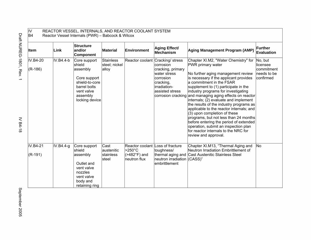
IV REACTOR VESSEL, INTERNALS, AND REACTOR COOLANT SYSTEM B4 Reactor Vessel Internals (PWR) – Babcock & Wilcox
Item Link Structure and/or Component
Material Environment Aging Effect/ Mechanism Aging Management Program (AMP) Further
Evaluation
IV.B4-20
(R-186)
IV.B4.4-b Core support shield assembly
Core support shield-to-core barrel bolts vent valve assembly locking device
Stainless steel; nickel alloy
Reactor coolant Cracking/ stress corrosion cracking, primary water stress corrosion cracking, irradiation-assisted stress corrosion cracking
Chapter XI.M2, "Water Chemistry" for PWR primary water
No further aging management review is necessary if the applicant provides a commitment in the FSAR supplement to (1) participate in the industry programs for investigating and managing aging effects on reactor internals; (2) evaluate and implement the results of the industry programs as applicable to the reactor internals; and (3) upon completion of these programs, but not less than 24 months before entering the period of extended operation, submit an inspection plan for reactor internals to the NRC for review and approval.
No, but licensee commitment needs to be confirmed
IV.B4-21
(R-191)
IV.B4.4-g Core support shield assembly
Outlet and vent valve nozzles vent valve body and retaining ring
Cast austenitic stainless steel
Reactor coolant >250°C (>482°F) and neutron flux
Loss of fracture toughness/ thermal aging and neutron irradiation embrittlement
Chapter XI.M13, “Thermal Aging and Neutron Irradiation Embrittlement of Cast Austenitic Stainless Steel (CASS)”
No
Draft N
UR
EG
-1801, Rev. 1
IV B
4-18 S
eptember 2005

IV REACTOR VESSEL, INTERNALS, AND REACTOR COOLANT SYSTEM B4 Reactor Vessel Internals (PWR) – Babcock & Wilcox
Item Link Structure and/or Component
Material Environment Aging Effect/ Mechanism Aging Management Program (AMP) Further
Evaluation
IV.B4-22
(R-209)
IV.B4.7-a Flow distributor assembly
Flow distributor head and flange Incore guide support plate Clamping ring
Stainless steel
Reactor coolant Cracking/ stress corrosion cracking, irradiation-assisted stress corrosion cracking
Chapter XI.M2, "Water Chemistry" for PWR primary water
No further aging management review is necessary if the applicant provides a commitment in the FSAR supplement to (1) participate in the industry programs for investigating and managing aging effects on reactor internals; (2) evaluate and implement the results of the industry programs as applicable to the reactor internals; and (3) upon completion of these programs, but not less than 24 months before entering the period of extended operation, submit an inspection plan for reactor internals to the NRC for review and approval.
No, but licensee commitment needs to be confirmed
Septem
ber 2005 IV
B4-19
Draft N
UR
EG
-1801, Rev. 1

IV REACTOR VESSEL, INTERNALS, AND REACTOR COOLANT SYSTEM B4 Reactor Vessel Internals (PWR) – Babcock & Wilcox
Item Link Structure and/or Component
Material Environment Aging Effect/ Mechanism Aging Management Program (AMP) Further
Evaluation
IV.B4-23
(R-211)
IV.B4.7-c Flow distributor assembly
Flow distributor head and flange Shell forging-to-flow distributor bolts Incore guide support plate Clamping ring
Stainless steel; nickel alloy
Reactor coolant Changes in dimensions/ void swelling
No further aging management review is necessary if the applicant provides a commitment in the FSAR supplement to (1) participate in the industry programs for investigating and managing aging effects on reactor internals; (2) evaluate and implement the results of the industry programs as applicable to the reactor internals; and (3) upon completion of these programs, but not less than 24 months before entering the period of extended operation, submit an inspection plan for reactor internals to the NRC for review and approval.
No, but licensee commitment needs to be confirmed
IV.B4-24
(R-212)
IV.B4.7-d Flow distributor assembly
Flow distributor head and flange Shell forging-to-flow distributor bolts Incore guide support plate Clamping ring
Stainless steel; nickel alloy
Reactor coolant and neutron flux
Loss of fracture toughness/ neutron irradiation embrittlement, void swelling
No further aging management review is necessary if the applicant provides a commitment in the FSAR supplement to (1) participate in the industry programs for investigating and managing aging effects on reactor internals; (2) evaluate and implement the results of the industry programs as applicable to the reactor internals; and (3) upon completion of these programs, but not less than 24 months before entering the period of extended operation, submit an inspection plan for reactor internals to the NRC for review and approval.
No, but licensee commitment needs to be confirmed
Draft N
UR
EG
-1801, Rev. 1
IV B
4-20 S
eptember 2005
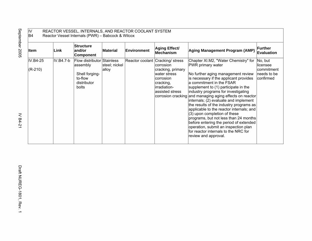
IV REACTOR VESSEL, INTERNALS, AND REACTOR COOLANT SYSTEM B4 Reactor Vessel Internals (PWR) – Babcock & Wilcox
Item Link Structure and/or Component
Material Environment Aging Effect/ Mechanism Aging Management Program (AMP) Further
Evaluation
IV.B4-25
(R-210)
IV.B4.7-b Flow distributor assembly
Shell forging-to-flow distributor bolts
Stainless steel; nickel alloy
Reactor coolant Cracking/ stress corrosion cracking, primary water stress corrosion cracking, irradiation-assisted stress corrosion cracking
Chapter XI.M2, "Water Chemistry" for PWR primary water
No further aging management review is necessary if the applicant provides a commitment in the FSAR supplement to (1) participate in the industry programs for investigating and managing aging effects on reactor internals; (2) evaluate and implement the results of the industry programs as applicable to the reactor internals; and (3) upon completion of these programs, but not less than 24 months before entering the period of extended operation, submit an inspection plan for reactor internals to the NRC for review and approval.
No, but licensee commitment needs to be confirmed
Septem
ber 2005 IV
B4-21
Draft N
UR
EG
-1801, Rev. 1
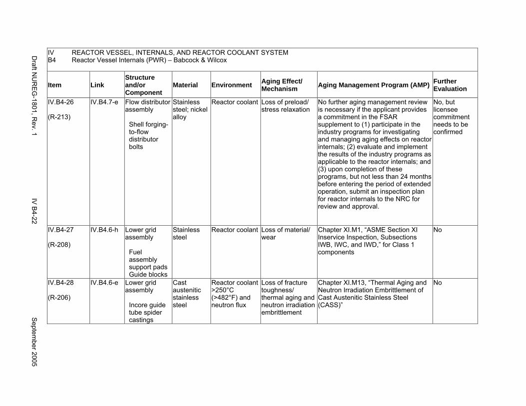
IV REACTOR VESSEL, INTERNALS, AND REACTOR COOLANT SYSTEM B4 Reactor Vessel Internals (PWR) – Babcock & Wilcox
Item Link Structure and/or Component
Material Environment Aging Effect/ Mechanism Aging Management Program (AMP) Further
Evaluation
IV.B4-26
(R-213)
IV.B4.7-e Flow distributor assembly
Shell forging-to-flow distributor bolts
Stainless steel; nickel alloy
Reactor coolant Loss of preload/ stress relaxation
No further aging management review is necessary if the applicant provides a commitment in the FSAR supplement to (1) participate in the industry programs for investigating and managing aging effects on reactor internals; (2) evaluate and implement the results of the industry programs as applicable to the reactor internals; and (3) upon completion of these programs, but not less than 24 months before entering the period of extended operation, submit an inspection plan for reactor internals to the NRC for review and approval.
No, but licensee commitment needs to be confirmed
IV.B4-27
(R-208)
IV.B4.6-h Lower grid assembly
Fuel assembly support pads Guide blocks
Stainless steel
Reactor coolant Loss of material/ wear
Chapter XI.M1, “ASME Section XI Inservice Inspection, Subsections IWB, IWC, and IWD,” for Class 1 components
No
IV.B4-28
(R-206)
IV.B4.6-e Lower grid assembly
Incore guide tube spider castings
Cast austenitic stainless steel
Reactor coolant >250°C (>482°F) and neutron flux
Loss of fracture toughness/ thermal aging and neutron irradiation embrittlement
Chapter XI.M13, “Thermal Aging and Neutron Irradiation Embrittlement of Cast Austenitic Stainless Steel (CASS)”
No
Draft N
UR
EG
-1801, Rev. 1
IV B
4-22 S
eptember 2005
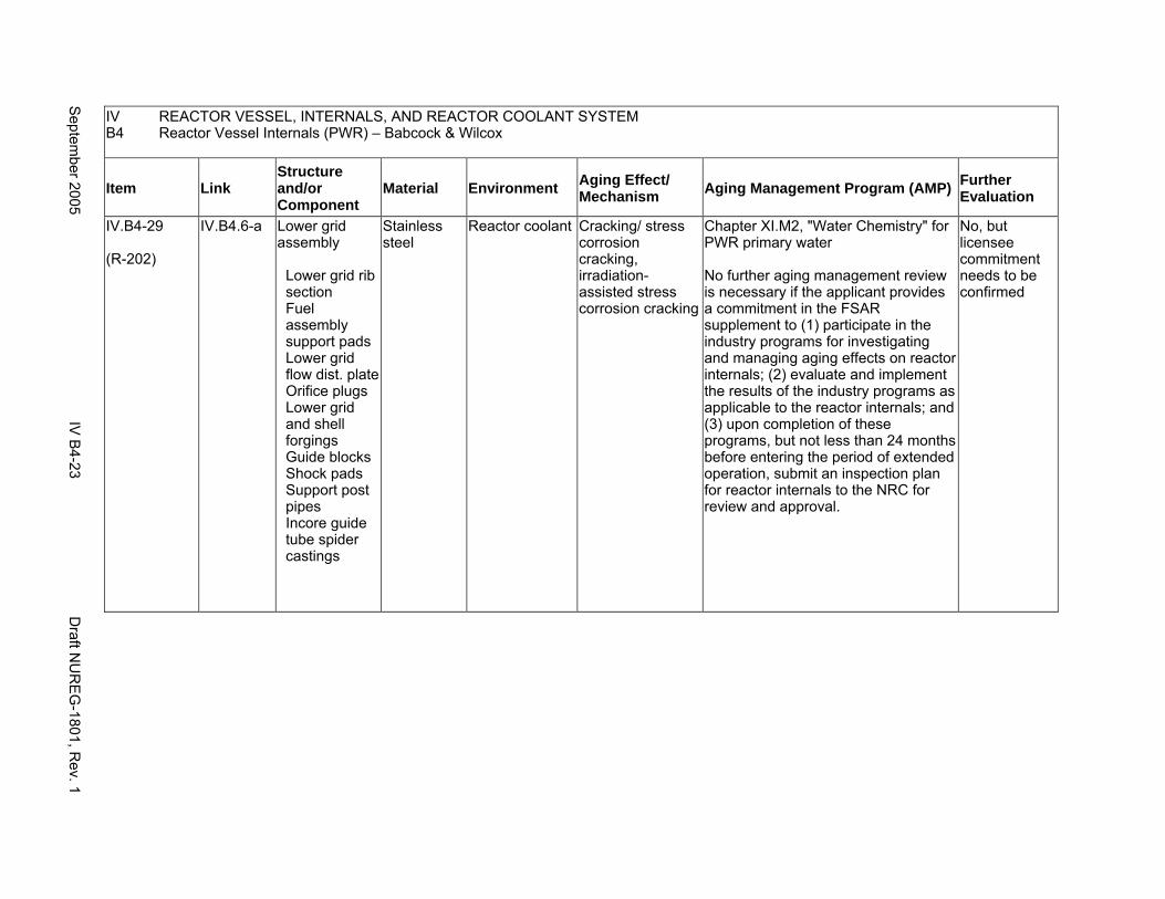
IV REACTOR VESSEL, INTERNALS, AND REACTOR COOLANT SYSTEM B4 Reactor Vessel Internals (PWR) – Babcock & Wilcox
Item Link Structure and/or Component
Material Environment Aging Effect/ Mechanism Aging Management Program (AMP) Further
Evaluation
IV.B4-29
(R-202)
IV.B4.6-a Lower grid assembly
Lower grid rib section Fuel assembly support pads Lower grid flow dist. plate Orifice plugs Lower grid and shell forgings Guide blocks Shock pads Support post pipes Incore guide tube spider castings
Stainless steel
Reactor coolant Cracking/ stress corrosion cracking, irradiation-assisted stress corrosion cracking
Chapter XI.M2, "Water Chemistry" for PWR primary water
No further aging management review is necessary if the applicant provides a commitment in the FSAR supplement to (1) participate in the industry programs for investigating and managing aging effects on reactor internals; (2) evaluate and implement the results of the industry programs as applicable to the reactor internals; and (3) upon completion of these programs, but not less than 24 months before entering the period of extended operation, submit an inspection plan for reactor internals to the NRC for review and approval.
No, but licensee commitment needs to be confirmed
Septem
ber 2005 IV
B4-23
Draft N
UR
EG
-1801, Rev. 1
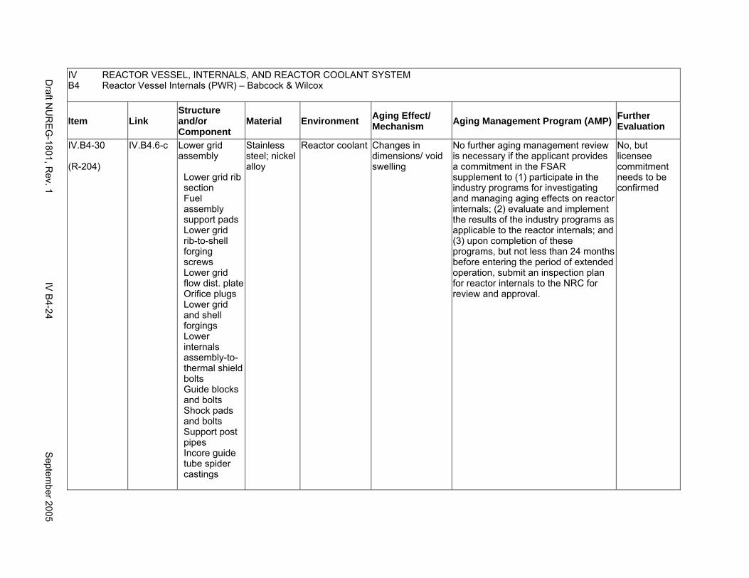
IV REACTOR VESSEL, INTERNALS, AND REACTOR COOLANT SYSTEM B4 Reactor Vessel Internals (PWR) – Babcock & Wilcox
Item Link Structure and/or Component
Material Environment Aging Effect/ Mechanism Aging Management Program (AMP) Further
Evaluation
IV.B4-30
(R-204)
IV.B4.6-c Lower grid assembly
Lower grid rib section Fuel assembly support pads Lower grid rib-to-shell forging screws Lower grid flow dist. plate Orifice plugs Lower grid and shell forgings Lower internals assembly-to- thermal shield bolts Guide blocks and bolts Shock pads and bolts Support post pipes Incore guide tube spider castings
Stainless steel; nickel alloy
Reactor coolant Changes in dimensions/ void swelling
No further aging management review is necessary if the applicant provides a commitment in the FSAR supplement to (1) participate in the industry programs for investigating and managing aging effects on reactor internals; (2) evaluate and implement the results of the industry programs as applicable to the reactor internals; and (3) upon completion of these programs, but not less than 24 months before entering the period of extended operation, submit an inspection plan for reactor internals to the NRC for review and approval.
No, but licensee commitment needs to be confirmed
Draft N
UR
EG
-1801, Rev. 1
IV B
4-24 S
eptember 2005
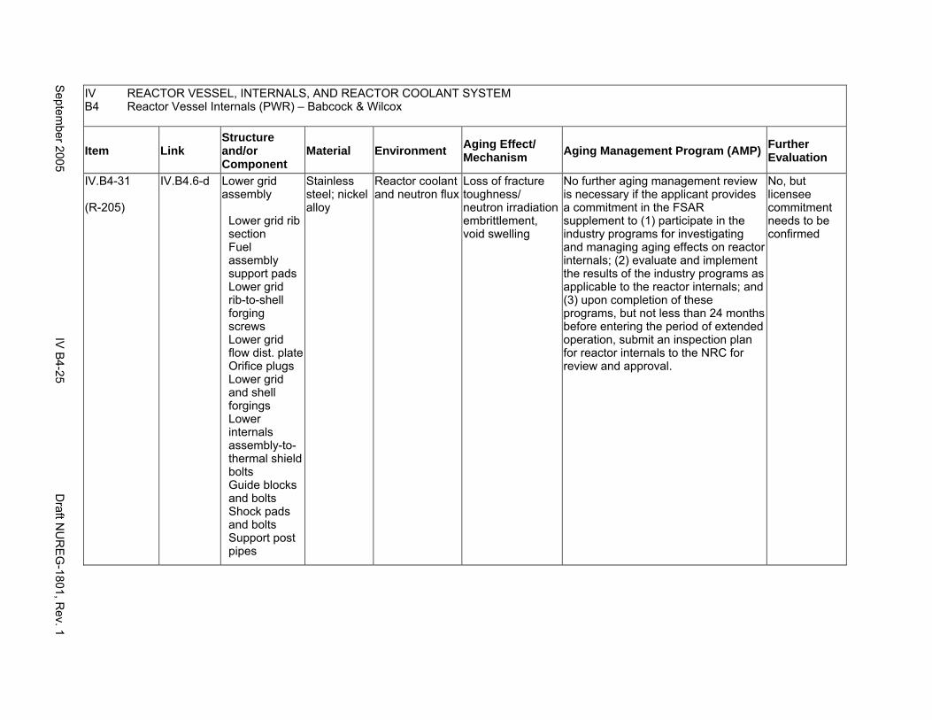
IV REACTOR VESSEL, INTERNALS, AND REACTOR COOLANT SYSTEM B4 Reactor Vessel Internals (PWR) – Babcock & Wilcox
Item Link Structure and/or Component
Material Environment Aging Effect/ Mechanism Aging Management Program (AMP) Further
Evaluation
IV.B4-31
(R-205)
IV.B4.6-d Lower grid assembly
Lower grid rib section Fuel assembly support pads Lower grid rib-to-shell forging screws Lower grid flow dist. plate Orifice plugs Lower grid and shell forgings Lower internals assembly-tothermal shield bolts Guide blocks and bolts Shock pads and bolts Support post pipes
Stainless steel; nickel alloy
Reactor coolant and neutron flux
Loss of fracture toughness/ neutron irradiation embrittlement, void swelling
No further aging management review is necessary if the applicant provides a commitment in the FSAR supplement to (1) participate in the industry programs for investigating and managing aging effects on reactor internals; (2) evaluate and implement the results of the industry programs as applicable to the reactor internals; and (3) upon completion of these programs, but not less than 24 months before entering the period of extended operation, submit an inspection plan for reactor internals to the NRC for review and approval.
No, but licensee commitment needs to be confirmed
Septem
ber 2005 IV
B4-25
Draft N
UR
EG
-1801, Rev. 1

IV REACTOR VESSEL, INTERNALS, AND REACTOR COOLANT SYSTEM B4 Reactor Vessel Internals (PWR) – Babcock & Wilcox
Item Link Structure and/or Component
Material Environment Aging Effect/ Mechanism Aging Management Program (AMP) Further
Evaluation
IV.B4-32
(R-203)
IV.B4.6-b Lower grid assembly
Lower grid rib-to-shell forging screws Lower internals assembly-to- thermal shield bolts Guide blocks bolts Shock pads bolts
Stainless steel; nickel alloy
Reactor coolant Cracking/ stress corrosion cracking, primary water stress corrosion cracking, irradiation-assisted stress corrosion cracking
Chapter XI.M2, "Water Chemistry" for PWR primary water
No further aging management review is necessary if the applicant provides a commitment in the FSAR supplement to (1) participate in the industry programs for investigating and managing aging effects on reactor internals; (2) evaluate and implement the results of the industry programs as applicable to the reactor internals; and (3) upon completion of these programs, but not less than 24 months before entering the period of extended operation, submit an inspection plan for reactor internals to the NRC for review and approval.
No, but licensee commitment needs to be confirmed
Draft N
UR
EG
-1801, Rev. 1
IV B
4-26 S
eptember 2005
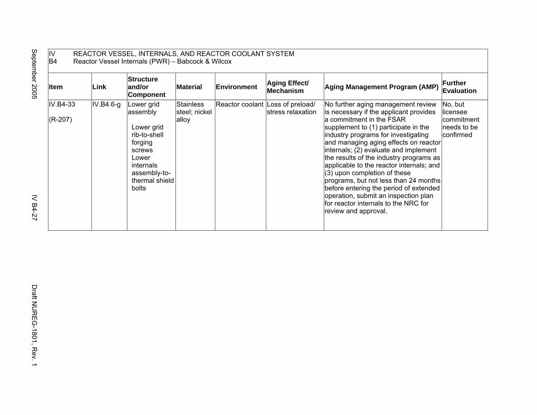
IV REACTOR VESSEL, INTERNALS, AND REACTOR COOLANT SYSTEM B4 Reactor Vessel Internals (PWR) – Babcock & Wilcox
Item Link Structure and/or Component
Material Environment Aging Effect/ Mechanism Aging Management Program (AMP) Further
Evaluation
IV.B4-33
(R-207)
IV.B4.6-g Lower grid assembly
Lower grid rib-to-shell forging screws Lower internals assembly-tothermal shield bolts
Stainless steel; nickel alloy
Reactor coolant Loss of preload/ stress relaxation
No further aging management review is necessary if the applicant provides a commitment in the FSAR supplement to (1) participate in the industry programs for investigating and managing aging effects on reactor internals; (2) evaluate and implement the results of the industry programs as applicable to the reactor internals; and (3) upon completion of these programs, but not less than 24 months before entering the period of extended operation, submit an inspection plan for reactor internals to the NRC for review and approval.
No, but licensee commitment needs to be confirmed
Septem
ber 2005 IV
B4-27
Draft N
UR
EG
-1801, Rev. 1
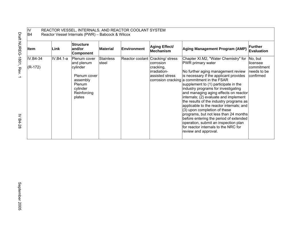
IV REACTOR VESSEL, INTERNALS, AND REACTOR COOLANT SYSTEM B4 Reactor Vessel Internals (PWR) – Babcock & Wilcox
Item Link Structure and/or Component
Material Environment Aging Effect/ Mechanism Aging Management Program (AMP) Further
Evaluation
IV.B4-34
(R-172)
IV.B4.1-a Plenum cover and plenum cylinder
Plenum cover assembly Plenum cylinder Reinforcing plates
Stainless steel
Reactor coolant Cracking/ stress corrosion cracking, irradiation-assisted stress corrosion cracking
Chapter XI.M2, "Water Chemistry" for PWR primary water
No further aging management review is necessary if the applicant provides a commitment in the FSAR supplement to (1) participate in the industry programs for investigating and managing aging effects on reactor internals; (2) evaluate and implement the results of the industry programs as applicable to the reactor internals; and (3) upon completion of these programs, but not less than 24 months before entering the period of extended operation, submit an inspection plan for reactor internals to the NRC for review and approval.
No, but licensee commitment needs to be confirmed
Draft N
UR
EG
-1801, Rev. 1
IV B
4-28 S
eptember 2005
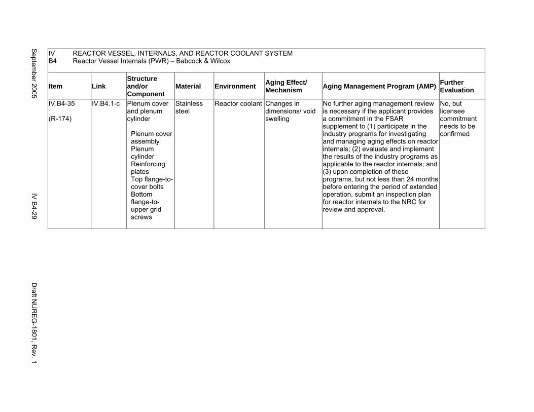
IV REACTOR VESSEL, INTERNALS, AND REACTOR COOLANT SYSTEM B4 Reactor Vessel Internals (PWR) – Babcock & Wilcox
Item Link Structure and/or Component
Material Environment Aging Effect/ Mechanism Aging Management Program (AMP) Further
Evaluation
IV.B4-35
(R-174)
IV.B4.1-c Plenum cover and plenum cylinder
Plenum cover assembly Plenum cylinder Reinforcing plates Top flange-tocover bolts Bottom flange-toupper grid screws
Stainless steel
Reactor coolant Changes in dimensions/ void swelling
No further aging management review is necessary if the applicant provides a commitment in the FSAR supplement to (1) participate in the industry programs for investigating and managing aging effects on reactor internals; (2) evaluate and implement the results of the industry programs as applicable to the reactor internals; and (3) upon completion of these programs, but not less than 24 months before entering the period of extended operation, submit an inspection plan for reactor internals to the NRC for review and approval.
No, but licensee commitment needs to be confirmed
Septem
ber 2005 IV
B4-29
Draft N
UR
EG
-1801, Rev. 1
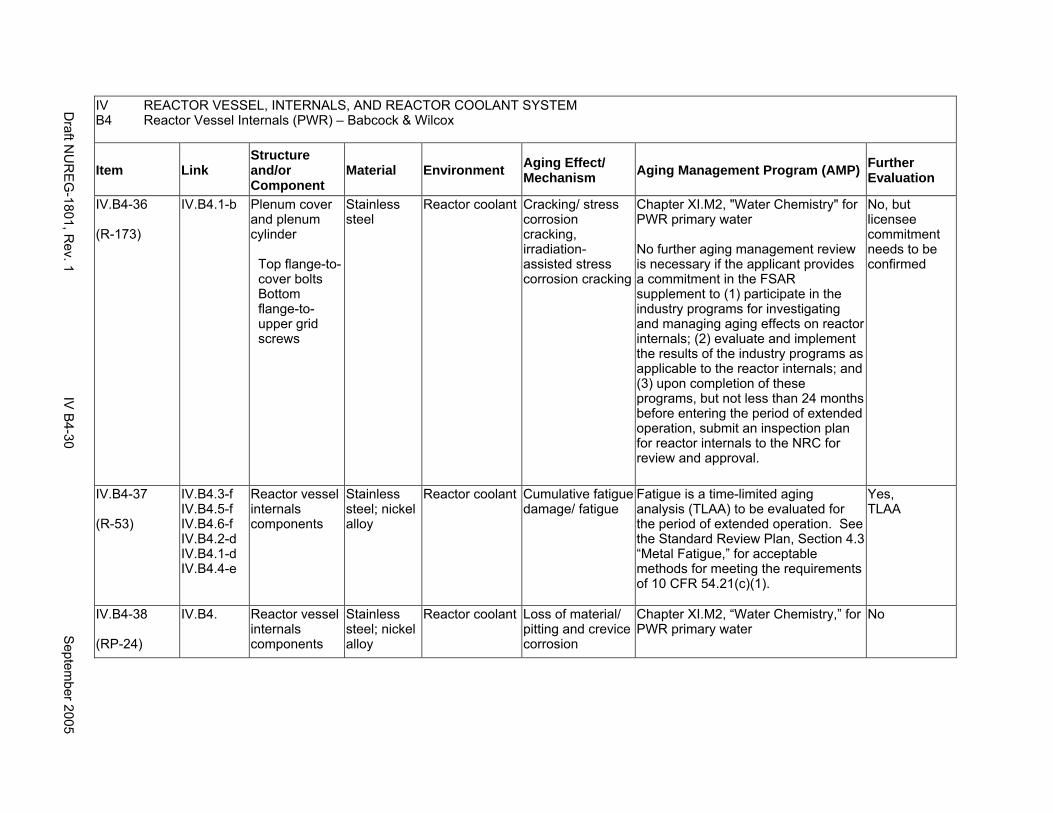
IV REACTOR VESSEL, INTERNALS, AND REACTOR COOLANT SYSTEM B4 Reactor Vessel Internals (PWR) – Babcock & Wilcox
Item Link Structure and/or Component
Material Environment Aging Effect/ Mechanism Aging Management Program (AMP) Further
Evaluation
IV.B4-36
(R-173)
IV.B4.1-b Plenum cover and plenum cylinder
Top flange-tocover bolts Bottom flange-toupper grid screws
Stainless steel
Reactor coolant Cracking/ stress corrosion cracking, irradiation-assisted stress corrosion cracking
Chapter XI.M2, "Water Chemistry" for PWR primary water
No further aging management review is necessary if the applicant provides a commitment in the FSAR supplement to (1) participate in the industry programs for investigating and managing aging effects on reactor internals; (2) evaluate and implement the results of the industry programs as applicable to the reactor internals; and (3) upon completion of these programs, but not less than 24 months before entering the period of extended operation, submit an inspection plan for reactor internals to the NRC for review and approval.
No, but licensee commitment needs to be confirmed
IV.B4-37
(R-53)
IV.B4.3-f IV.B4.5-f IV.B4.6-f IV.B4.2-d IV.B4.1-d IV.B4.4-e
Reactor vessel internals components
Stainless steel; nickel alloy
Reactor coolant Cumulative fatigue damage/ fatigue
Fatigue is a time-limited aging analysis (TLAA) to be evaluated for the period of extended operation. See the Standard Review Plan, Section 4.3 “Metal Fatigue,” for acceptable methods for meeting the requirements of 10 CFR 54.21(c)(1).
Yes, TLAA
IV.B4-38
(RP-24)
IV.B4. Reactor vessel internals components
Stainless steel; nickel alloy
Reactor coolant Loss of material/ pitting and crevice corrosion
Chapter XI.M2, “Water Chemistry,” for PWR primary water
No
Draft N
UR
EG
-1801, Rev. 1
IV B
4-30 S
eptember 2005
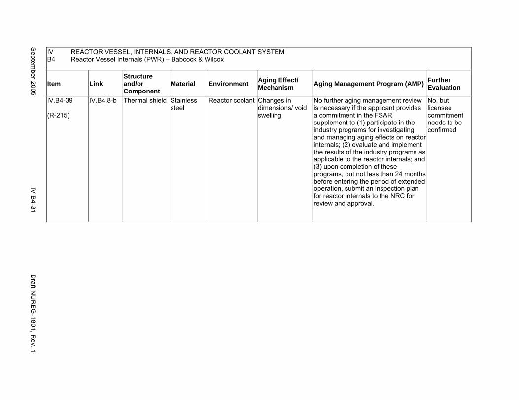
IV REACTOR VESSEL, INTERNALS, AND REACTOR COOLANT SYSTEM B4 Reactor Vessel Internals (PWR) – Babcock & Wilcox
Item Link Structure and/or Component
Material Environment Aging Effect/ Mechanism Aging Management Program (AMP) Further
Evaluation
IV.B4-39
(R-215)
IV.B4.8-b Thermal shield Stainless steel
Reactor coolant Changes in dimensions/ void swelling
No further aging management review is necessary if the applicant provides a commitment in the FSAR supplement to (1) participate in the industry programs for investigating and managing aging effects on reactor internals; (2) evaluate and implement the results of the industry programs as applicable to the reactor internals; and (3) upon completion of these programs, but not less than 24 months before entering the period of extended operation, submit an inspection plan for reactor internals to the NRC for review and approval.
No, but licensee commitment needs to be confirmed
Septem
ber 2005 IV
B4-31
Draft N
UR
EG
-1801, Rev. 1
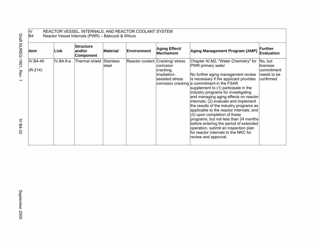
IV REACTOR VESSEL, INTERNALS, AND REACTOR COOLANT SYSTEM B4 Reactor Vessel Internals (PWR) – Babcock & Wilcox
Item Link Structure and/or Component
Material Environment Aging Effect/ Mechanism Aging Management Program (AMP) Further
Evaluation
IV.B4-40
(R-214)
IV.B4.8-a Thermal shield Stainless steel
Reactor coolant Cracking/ stress corrosion cracking, irradiation-assisted stress corrosion cracking
Chapter XI.M2, "Water Chemistry" for PWR primary water
No further aging management review is necessary if the applicant provides a commitment in the FSAR supplement to (1) participate in the industry programs for investigating and managing aging effects on reactor internals; (2) evaluate and implement the results of the industry programs as applicable to the reactor internals; and (3) upon completion of these programs, but not less than 24 months before entering the period of extended operation, submit an inspection plan for reactor internals to the NRC for review and approval.
No, but licensee commitment needs to be confirmed
Draft N
UR
EG
-1801, Rev. 1
IV B
4-32 S
eptember 2005
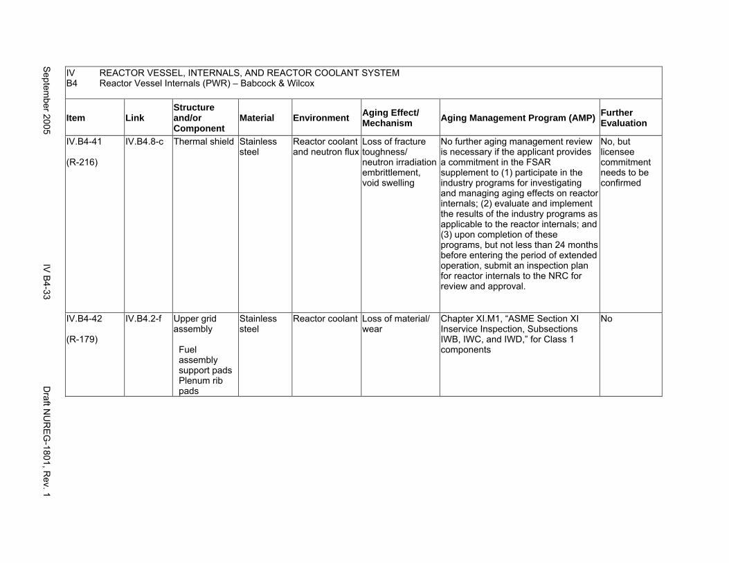
IV REACTOR VESSEL, INTERNALS, AND REACTOR COOLANT SYSTEM B4 Reactor Vessel Internals (PWR) – Babcock & Wilcox
Item Link Structure and/or Component
Material Environment Aging Effect/ Mechanism Aging Management Program (AMP) Further
Evaluation
IV.B4-41
(R-216)
IV.B4.8-c Thermal shield Stainless steel
Reactor coolant and neutron flux
Loss of fracture toughness/ neutron irradiation embrittlement, void swelling
No further aging management review is necessary if the applicant provides a commitment in the FSAR supplement to (1) participate in the industry programs for investigating and managing aging effects on reactor internals; (2) evaluate and implement the results of the industry programs as applicable to the reactor internals; and (3) upon completion of these programs, but not less than 24 months before entering the period of extended operation, submit an inspection plan for reactor internals to the NRC for review and approval.
No, but licensee commitment needs to be confirmed
IV.B4-42
(R-179)
IV.B4.2-f Upper grid assembly
Fuel assembly support pads Plenum rib pads
Stainless steel
Reactor coolant Loss of material/ wear
Chapter XI.M1, “ASME Section XI Inservice Inspection, Subsections IWB, IWC, and IWD,” for Class 1 components
No
Septem
ber 2005 IV
B4-33
Draft N
UR
EG
-1801, Rev. 1
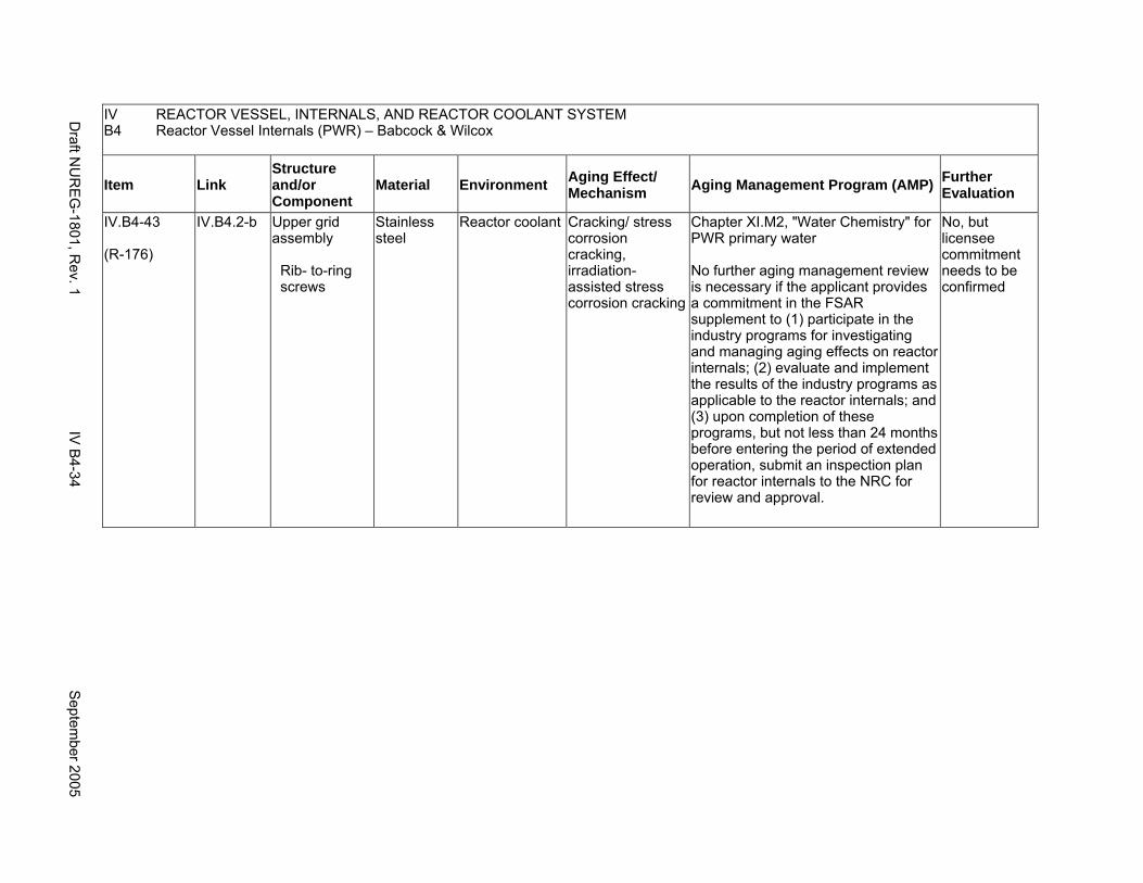
IV REACTOR VESSEL, INTERNALS, AND REACTOR COOLANT SYSTEM B4 Reactor Vessel Internals (PWR) – Babcock & Wilcox
Item Link Structure and/or Component
Material Environment Aging Effect/ Mechanism Aging Management Program (AMP) Further
Evaluation
IV.B4-43
(R-176)
IV.B4.2-b Upper grid assembly
Rib- to-ring screws
Stainless steel
Reactor coolant Cracking/ stress corrosion cracking, irradiation-assisted stress corrosion cracking
Chapter XI.M2, "Water Chemistry" for PWR primary water
No further aging management review is necessary if the applicant provides a commitment in the FSAR supplement to (1) participate in the industry programs for investigating and managing aging effects on reactor internals; (2) evaluate and implement the results of the industry programs as applicable to the reactor internals; and (3) upon completion of these programs, but not less than 24 months before entering the period of extended operation, submit an inspection plan for reactor internals to the NRC for review and approval.
No, but licensee commitment needs to be confirmed
Draft N
UR
EG
-1801, Rev. 1
IV B
4-34 S
eptember 2005
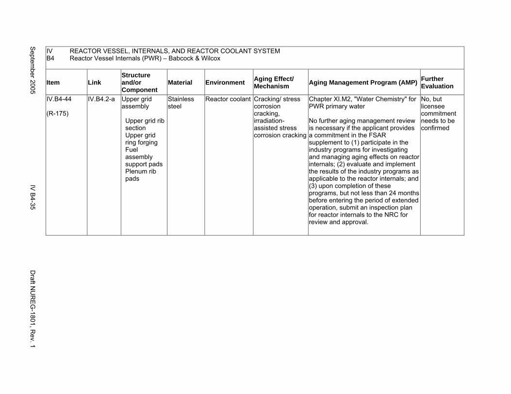
IV REACTOR VESSEL, INTERNALS, AND REACTOR COOLANT SYSTEM B4 Reactor Vessel Internals (PWR) – Babcock & Wilcox
Item Link Structure and/or Component
Material Environment Aging Effect/ Mechanism Aging Management Program (AMP) Further
Evaluation
IV.B4-44
(R-175)
IV.B4.2-a Upper grid assembly
Upper grid rib section Upper grid ring forging Fuel assembly support pads Plenum rib pads
Stainless steel
Reactor coolant Cracking/ stress corrosion cracking, irradiation-assisted stress corrosion cracking
Chapter XI.M2, "Water Chemistry" for PWR primary water
No further aging management review is necessary if the applicant provides a commitment in the FSAR supplement to (1) participate in the industry programs for investigating and managing aging effects on reactor internals; (2) evaluate and implement the results of the industry programs as applicable to the reactor internals; and (3) upon completion of these programs, but not less than 24 months before entering the period of extended operation, submit an inspection plan for reactor internals to the NRC for review and approval.
No, but licensee commitment needs to be confirmed
Septem
ber 2005 IV
B4-35
Draft N
UR
EG
-1801, Rev. 1

IV REACTOR VESSEL, INTERNALS, AND REACTOR COOLANT SYSTEM B4 Reactor Vessel Internals (PWR) – Babcock & Wilcox
Item Link Structure and/or Component
Material Environment Aging Effect/ Mechanism Aging Management Program (AMP) Further
Evaluation
IV.B4-45
(R-177)
IV.B4.2-c Upper grid assembly
Upper grid rib section Upper grid ring forging Fuel assembly support pads Plenum rib pads Rib-to-ring screws
Stainless steel
Reactor coolant Changes in dimensions/ void swelling
No further aging management review is necessary if the applicant provides a commitment in the FSAR supplement to (1) participate in the industry programs for investigating and managing aging effects on reactor internals; (2) evaluate and implement the results of the industry programs as applicable to the reactor internals; and (3) upon completion of these programs, but not less than 24 months before entering the period of extended operation, submit an inspection plan for reactor internals to the NRC for review and approval.
No, but licensee commitment needs to be confirmed
IV.B4-46
(R-178)
IV.B4.2-e Upper grid assembly
Upper grid rib section Upper grid ring forging Fuel assembly support pads Plenum rib pads Rib-to-ring screws
Stainless steel
Reactor coolant and neutron flux
Loss of fracture toughness/ neutron irradiation embrittlement, void swelling
No further aging management review is necessary if the applicant provides a commitment in the FSAR supplement to (1) participate in the industry programs for investigating and managing aging effects on reactor internals; (2) evaluate and implement the results of the industry programs as applicable to the reactor internals; and (3) upon completion of these programs, but not less than 24 months before entering the period of extended operation, submit an inspection plan for reactor internals to the NRC for review and approval.
No, but licensee commitment needs to be confirmed
Draft N
UR
EG
-1801, Rev. 1
IV B
4-36 S
eptember 2005
C1. REACTOR COOLANT PRESSURE BOUNDARY (BOILING WATER REACTOR)
Systems, Structures, and Components
This section addresses the boiling water reactor (BWR) primary coolant pressure boundary and consists of the reactor coolant recirculation system and portions of other systems connected to the pressure vessel extending to the second containment isolation valve or to the first anchor point outside containment. The connected systems include the residual heat removal (RHR), low–pressure core spray (LPCS), high–pressure core spray (HPCS), low–pressure coolant injection (LPCI), high–pressure coolant injection (HPCI), reactor core isolation cooling (RCIC), isolation condenser (IC), reactor water cleanup (RWC), standby liquid control (SLC), feedwater (FW), and main steam (MS) systems; and the steam line to the HPCI and RCIC pump turbines. Based on Regulatory Guide 1.26, “Quality Group Classifications and Standards for Water-, Steam-, and Radioactive-Waste-Containing Components of Nuclear Power Plants,” all systems, structures, and components that comprise the reactor coolant pressure boundary are governed by Group A Quality Standards.
Pump and valve internals perform their intended functions with moving parts or with a change in configuration, or are subject to replacement based on qualified life or specified time period. Pursuant to 10 CFR 54.21(a)(1), therefore, they are not subject to an aging management review.
Common miscellaneous material/environment combinations where aging effects are not expected to degrade the ability of the structure or component to perform its intended function for the extended period of operation are included in IV.E.
System Interfaces
The systems that interface with the reactor coolant pressure boundary include the reactor pressure vessel (IV.A1), the emergency core cooling system (V.D2), the standby liquid control system (VII.E2), the reactor water cleanup system (VII.E3), the shutdown cooling system (older plants) (VII.E4), the main steam system (VIII.B2), and the feedwater system (VIII.D2).
September 2005 IV C1-1 Draft NUREG-1801, Rev. 1
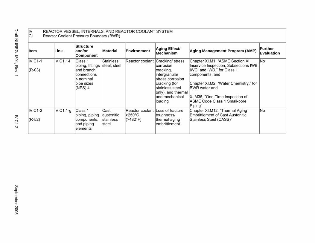
IV REACTOR VESSEL, INTERNALS, AND REACTOR COOLANT SYSTEM C1 Reactor Coolant Pressure Boundary (BWR)
Item Link Structure and/or Component
Material Environment Aging Effect/ Mechanism Aging Management Program (AMP) Further
Evaluation
IV.C1-1
(R-03)
IV.C1.1-i Class 1 piping, fittings and branch connections < nominal pipe sizes (NPS) 4
Stainless steel; steel
Reactor coolant Cracking/ stress corrosion cracking, intergranular stress corrosion cracking (for stainless steel only), and thermal and mechanical loading
Chapter XI.M1, “ASME Section XI Inservice Inspection, Subsections IWB, IWC, and IWD,” for Class 1 components, and
Chapter XI.M2, “Water Chemistry,” for BWR water and
XI.M35, "One-Time Inspection of ASME Code Class 1 Small-bore Piping"
No
IV.C1-2
(R-52)
IV.C1.1-g Class 1 piping, piping components, and piping elements
Cast austenitic stainless steel
Reactor coolant >250°C (>482°F)
Loss of fracture toughness/ thermal aging embrittlement
Chapter XI.M12, “Thermal Aging Embrittlement of Cast Austenitic Stainless Steel (CASS)”
No
Draft N
UR
EG
-1801, Rev. 1
IV C
1-2 S
eptember 2005

IV REACTOR VESSEL, INTERNALS, AND REACTOR COOLANT SYSTEM C1 Reactor Coolant Pressure Boundary (BWR)
Item Link Structure and/or Component
Material Environment Aging Effect/ Mechanism Aging Management Program (AMP) Further
Evaluation
IV.C1-3
(R-08)
IV.C1.2-c IV.C1.3-b
Class 1 pump casings, and valve bodies and bonnets
Cast austenitic stainless steel
Reactor coolant >250°C (>482°F)
Loss of fracture toughness/ thermal aging embrittlement
Chapter XI.M1, “ASME Section XI Inservice Inspection, Subsections IWB, IWC, and IWD,” for Class 1 components
For pump casings and valve bodies, screening for susceptibility to thermal aging is not necessary. The ASME Section XI inspection requirements are sufficient for managing the effects of loss of fracture toughness due to thermal aging embrittlement of CASS pump casings and valve bodies. Alternatively, the requirements of ASME Code Case N-481 for pump casings are sufficient for managing the effects of loss of fracture toughness due to thermal aging embrittlement of CASS pump casings.
No
Septem
ber 2005 IV
C1-3
Draft N
UR
EG
-1801, Rev. 1
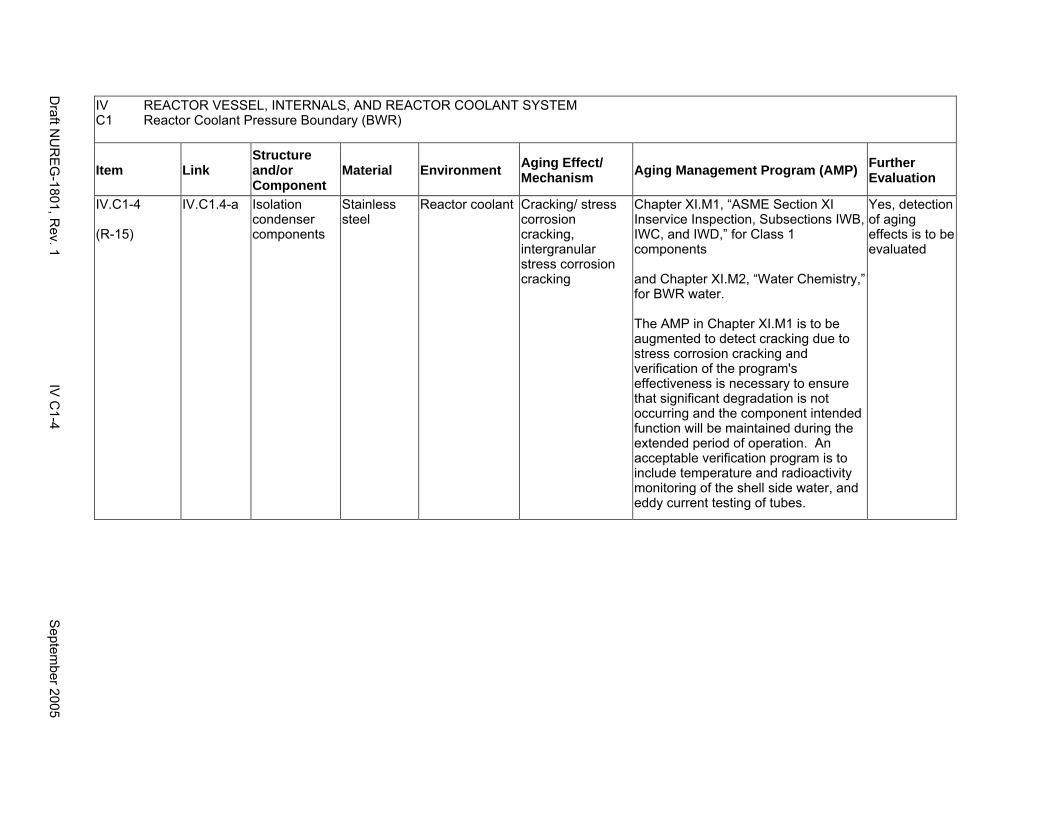
IV REACTOR VESSEL, INTERNALS, AND REACTOR COOLANT SYSTEM C1 Reactor Coolant Pressure Boundary (BWR)
Item Link Structure and/or Component
Material Environment Aging Effect/ Mechanism Aging Management Program (AMP) Further
Evaluation
IV.C1-4
(R-15)
IV.C1.4-a Isolation condenser components
Stainless steel
Reactor coolant Cracking/ stress corrosion cracking, intergranular stress corrosion cracking
Chapter XI.M1, “ASME Section XI Inservice Inspection, Subsections IWB, IWC, and IWD,” for Class 1 components
and Chapter XI.M2, “Water Chemistry,” for BWR water.
The AMP in Chapter XI.M1 is to be augmented to detect cracking due to stress corrosion cracking and verification of the program's effectiveness is necessary to ensure that significant degradation is not occurring and the component intended function will be maintained during the extended period of operation. An acceptable verification program is to include temperature and radioactivity monitoring of the shell side water, and eddy current testing of tubes.
Yes, detection of aging effects is to be evaluated
Draft N
UR
EG
-1801, Rev. 1
IV C
1-4 S
eptember 2005
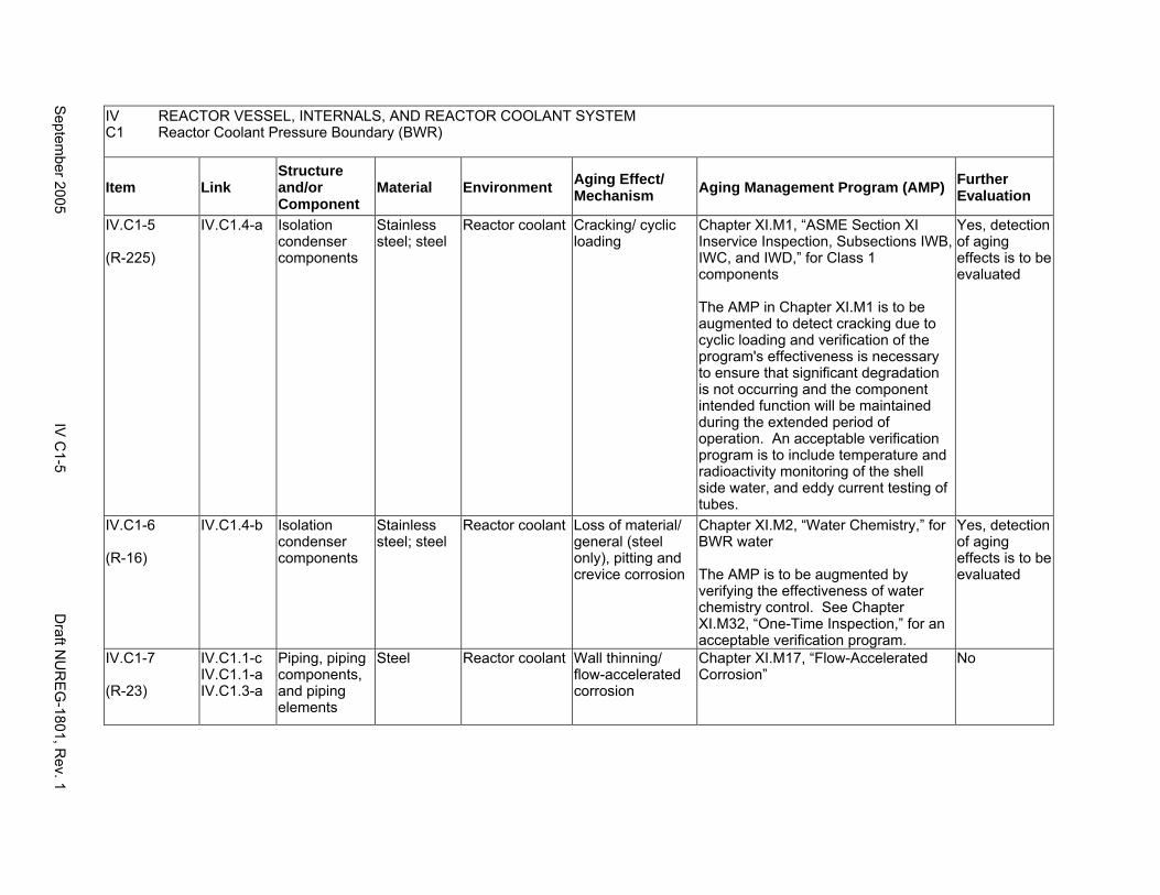
IV REACTOR VESSEL, INTERNALS, AND REACTOR COOLANT SYSTEM C1 Reactor Coolant Pressure Boundary (BWR)
Item Link Structure and/or Component
Material Environment Aging Effect/ Mechanism Aging Management Program (AMP) Further
Evaluation
IV.C1-5
(R-225)
IV.C1.4-a Isolation condenser components
Stainless steel; steel
Reactor coolant Cracking/ cyclic loading
Chapter XI.M1, “ASME Section XI Inservice Inspection, Subsections IWB, IWC, and IWD,” for Class 1 components
The AMP in Chapter XI.M1 is to be augmented to detect cracking due to cyclic loading and verification of the program's effectiveness is necessary to ensure that significant degradation is not occurring and the component intended function will be maintained during the extended period of operation. An acceptable verification program is to include temperature and radioactivity monitoring of the shell side water, and eddy current testing of tubes.
Yes, detection of aging effects is to be evaluated
IV.C1-6
(R-16)
IV.C1.4-b Isolation condenser components
Stainless steel; steel
Reactor coolant Loss of material/ general (steel only), pitting and crevice corrosion
Chapter XI.M2, “Water Chemistry,” for BWR water
The AMP is to be augmented by verifying the effectiveness of water chemistry control. See Chapter XI.M32, “One-Time Inspection,” for an acceptable verification program.
Yes, detection of aging effects is to be evaluated
IV.C1-7
(R-23)
IV.C1.1-c IV.C1.1-a IV.C1.3-a
Piping, piping components, and piping elements
Steel Reactor coolant Wall thinning/ flow-accelerated corrosion
Chapter XI.M17, “Flow-Accelerated Corrosion”
No
Septem
ber 2005 IV
C1-5
Draft N
UR
EG
-1801, Rev. 1
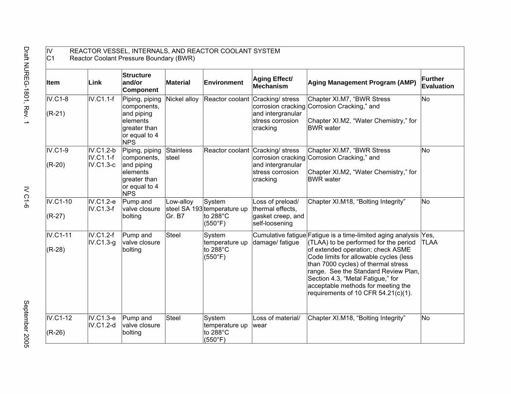
IV REACTOR VESSEL, INTERNALS, AND REACTOR COOLANT SYSTEM C1 Reactor Coolant Pressure Boundary (BWR)
Item Link Structure and/or Component
Material Environment Aging Effect/ Mechanism Aging Management Program (AMP) Further
Evaluation
IV.C1-8
(R-21)
IV.C1.1-f Piping, piping components, and piping elements greater than or equal to 4 NPS
Nickel alloy Reactor coolant Cracking/ stress corrosion cracking and intergranular stress corrosion cracking
Chapter XI.M7, “BWR Stress Corrosion Cracking,” and
Chapter XI.M2, “Water Chemistry,” for BWR water
No
IV.C1-9
(R-20)
IV.C1.2-b IV.C1.1-f IV.C1.3-c
Piping, piping components, and piping elements greater than or equal to 4 NPS
Stainless steel
Reactor coolant Cracking/ stress corrosion cracking and intergranular stress corrosion cracking
Chapter XI.M7, “BWR Stress Corrosion Cracking,” and
Chapter XI.M2, “Water Chemistry,” for BWR water
No
IV.C1-10
(R-27)
IV.C1.2-e IV.C1.3-f
Pump and valve closure bolting
Low-alloy steel SA 193 Gr. B7
System temperature up to 288°C (550°F)
Loss of preload/ thermal effects, gasket creep, and self-loosening
Chapter XI.M18, “Bolting Integrity” No
IV.C1-11
(R-28)
IV.C1.2-f IV.C1.3-g
Pump and valve closure bolting
Steel System temperature up to 288°C (550°F)
Cumulative fatigue damage/ fatigue
Fatigue is a time-limited aging analysis (TLAA) to be performed for the period of extended operation; check ASME Code limits for allowable cycles (less than 7000 cycles) of thermal stress range. See the Standard Review Plan, Section 4.3, “Metal Fatigue,” for acceptable methods for meeting the requirements of 10 CFR 54.21(c)(1).
Yes, TLAA
IV.C1-12
(R-26)
IV.C1.3-e IV.C1.2-d
Pump and valve closure bolting
Steel System temperature up to 288°C (550°F)
Loss of material/ wear
Chapter XI.M18, “Bolting Integrity” No
Draft N
UR
EG
-1801, Rev. 1
IV C
1-6 S
eptember 2005
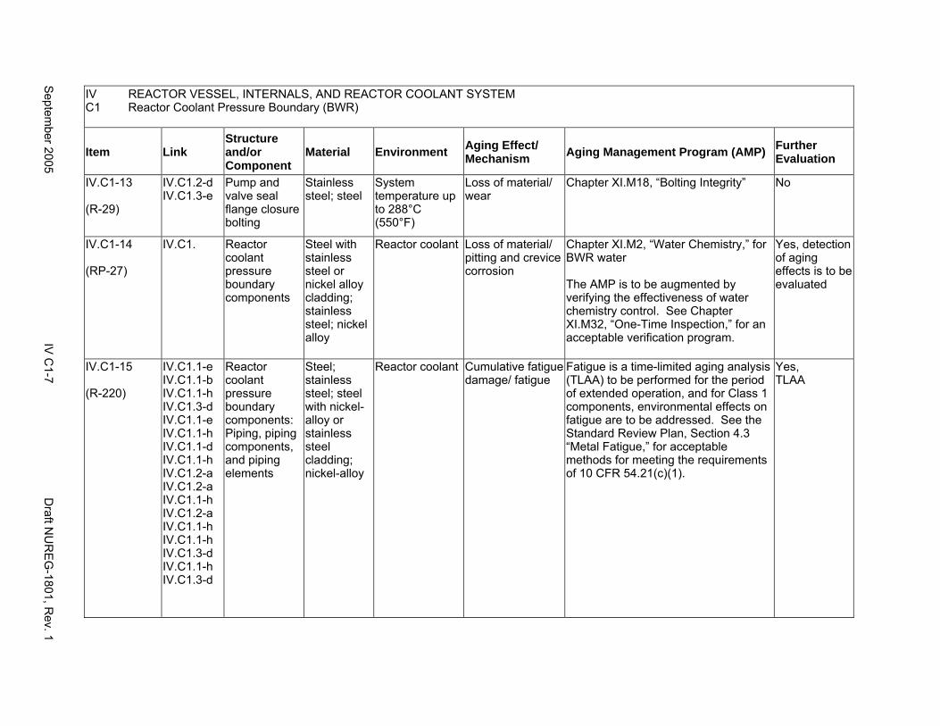
IV REACTOR VESSEL, INTERNALS, AND REACTOR COOLANT SYSTEM C1 Reactor Coolant Pressure Boundary (BWR)
Item Link Structure and/or Component
Material Environment Aging Effect/ Mechanism Aging Management Program (AMP) Further
Evaluation
IV.C1-13
(R-29)
IV.C1.2-d IV.C1.3-e
Pump and valve seal flange closure bolting
Stainless steel; steel
System temperature up to 288°C (550°F)
Loss of material/ wear
Chapter XI.M18, “Bolting Integrity” No
IV.C1-14
(RP-27)
IV.C1. Reactor coolant pressure boundary components
Steel with stainless steel or nickel alloy cladding; stainless steel; nickel alloy
Reactor coolant Loss of material/ pitting and crevice corrosion
Chapter XI.M2, “Water Chemistry,” for BWR water
The AMP is to be augmented by verifying the effectiveness of water chemistry control. See Chapter XI.M32, “One-Time Inspection,” for an acceptable verification program.
Yes, detection of aging effects is to be evaluated
IV.C1-15
(R-220)
IV.C1.1-e IV.C1.1-b IV.C1.1-h IV.C1.3-d IV.C1.1-e IV.C1.1-h IV.C1.1-d IV.C1.1-h IV.C1.2-a IV.C1.2-a IV.C1.1-h IV.C1.2-a IV.C1.1-h IV.C1.1-h IV.C1.3-d IV.C1.1-h IV.C1.3-d
Reactor coolant pressure boundary components: Piping, piping components, and piping elements
Steel; stainless steel; steel with nickel-alloy or stainless steel cladding; nickel-alloy
Reactor coolant Cumulative fatigue damage/ fatigue
Fatigue is a time-limited aging analysis (TLAA) to be performed for the period of extended operation, and for Class 1 components, environmental effects on fatigue are to be addressed. See the Standard Review Plan, Section 4.3 “Metal Fatigue,” for acceptable methods for meeting the requirements of 10 CFR 54.21(c)(1).
Yes, TLAA
Septem
ber 2005 IV
C1-7
Draft N
UR
EG
-1801, Rev. 1

This Page Intentionally Left Blank
Draft NUREG-1801, Rev. 1 IV C1-8 September 2005
C2. REACTOR COOLANT SYSTEM AND CONNECTED LINES (PRESSURIZED WATER REACTOR)
Systems, Structures, and Components
This section addresses the pressurized water reactor (PWR) primary coolant pressure boundary and consists of the reactor coolant system and portions of other connected systems generally extending up to and including the second containment isolation valve or to the first anchor point and including the containment isolation valves, the reactor coolant pump, valves, pressurizer, and the pressurizer relief tank. The connected systems include the residual heat removal (RHR) or low pressure injection system, high pressure injection system, sampling system, and the small-bore piping. With respect to other systems such as the core flood spray (CFS) or the safety injection tank (SIT) and the chemical and volume control system (CVCS), the isolation valves associated with the boundary between ASME Code class 1 and 2 are located inside the containment. Based on Regulatory Guide 1.26, “Quality Group Classifications and Standards for Water-, Steam-, and Radioactive-Waste-Containing Components of Nuclear Power Plants,” and with the exception of the pressurizer relief tank, which is governed by Group B Quality Standards, all systems, structures, and components that comprise the reactor coolant system are governed by Group A Quality Standards. The recirculating pump seal water heat exchanger is discussed in V.D1.
Pump and valve internals perform their intended functions with moving parts or with a change in configuration, or are subject to replacement based on qualified life or specified time period. Pursuant to 10 CFR 54.21(a)(1), therefore, they are not subject to an aging management review.
Common miscellaneous material/environment combinations where aging effects are not expected to degrade the ability of the structure or component to perform its intended function for the extended period of operation are included in IV.E.
System Interfaces
The systems that interface with the reactor coolant pressure boundary include the reactor pressure vessel (IV.A2), the steam generators (IV.D1 and IV.D2), the emergency core cooling system (V.D1), and the chemical and volume control system (VII.E1).
September 2005 IV C2-1 Draft NUREG-1801, Rev. 1
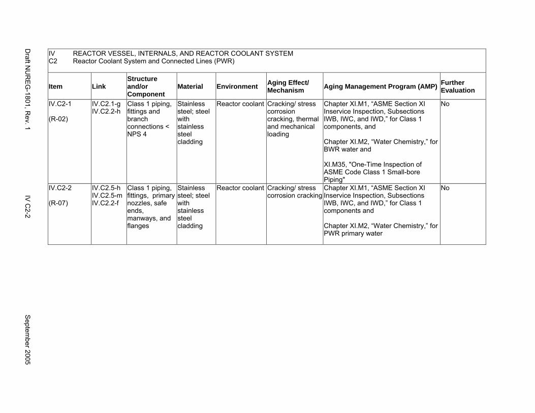
IV C2
REACTOR VESSEL, INTERNALS, AND REACTOR COOLANT SYSTEM Reactor Coolant System and Connected Lines (PWR)
Item Link Structure and/or Component
Material Environment Aging Effect/ Mechanism Aging Management Program (AMP) Further
Evaluation
IV.C2-1
(R-02)
IV.C2.1-g IV.C2.2-h
Class 1 piping, fittings and branch connections < NPS 4
Stainless steel; steel with stainless steel cladding
Reactor coolant Cracking/ stress corrosion cracking, thermal and mechanical loading
Chapter XI.M1, “ASME Section XI Inservice Inspection, Subsections IWB, IWC, and IWD,” for Class 1 components, and
Chapter XI.M2, “Water Chemistry,” for BWR water and
XI.M35, "One-Time Inspection of ASME Code Class 1 Small-bore Piping"
No
IV.C2-2
(R-07)
IV.C2.5-h IV.C2.5-m IV.C2.2-f
Class 1 piping, fittings, primary nozzles, safe ends, manways, and flanges
Stainless steel; steel with stainless steel cladding
Reactor coolant Cracking/ stress corrosion cracking
Chapter XI.M1, “ASME Section XI Inservice Inspection, Subsections IWB, IWC, and IWD,” for Class 1 components and
Chapter XI.M2, “Water Chemistry,” for PWR primary water
No
Draft N
UR
EG
-1801, Rev. 1
IV C
2-2 S
eptember 2005

IV C2
REACTOR VESSEL, INTERNALS, AND REACTOR COOLANT SYSTEM Reactor Coolant System and Connected Lines (PWR)
Item Link Structure and/or Component
Material Environment Aging Effect/ Mechanism Aging Management Program (AMP) Further
Evaluation
IV.C2-3
(R-05)
IV.C2.2-g IV.C2.5-i IV.C2.1-e
Class 1 piping, piping components, and piping elements
Cast austenitic stainless steel
Reactor coolant Cracking/ stress corrosion cracking
Monitoring and control of primary water chemistry in accordance with the guidelines in EPRI TR-105714 (Rev. 3 or later) minimize the potential of SCC, and material selection according to NUREG-0313, Rev. 2 guidelines of ≤0.035% C and ≥7.5% ferrite reduces susceptibility to SCC.
For CASS components that do not meet either one of the above guidelines, a plant-specific aging management program is to be evaluated. The program is to include (a) adequate inspection methods to ensure detection of cracks, and (b) flaw evaluation methodology for CASS components that are susceptible to thermal aging embrittlement.
Yes, plant-specific
IV.C2-4
(R-52)
IV.C2.5-l IV.C2.1-f IV.C2.2-e
Class 1 piping, piping components, and piping elements
Cast austenitic stainless steel
Reactor coolant >250°C (>482°F)
Loss of fracture toughness/ thermal aging embrittlement
Chapter XI.M12, “Thermal Aging Embrittlement of Cast Austenitic Stainless Steel (CASS)”
No
IV.C2-5
(R-09)
IV.C2.3-b IV.C2.4-b
Class 1 pump casings and valve bodies
Stainless steel; steel with stainless steel cladding
Reactor coolant Cracking/ stress corrosion cracking
Chapter XI.M1, “ASME Section XI Inservice Inspection, Subsections IWB, IWC, and IWD,” for Class 1 components and
Chapter XI.M2, “Water Chemistry,” for PWR primary water
No
Septem
ber 2005 IV
C2-3
Draft N
UR
EG
-1801, Rev. 1
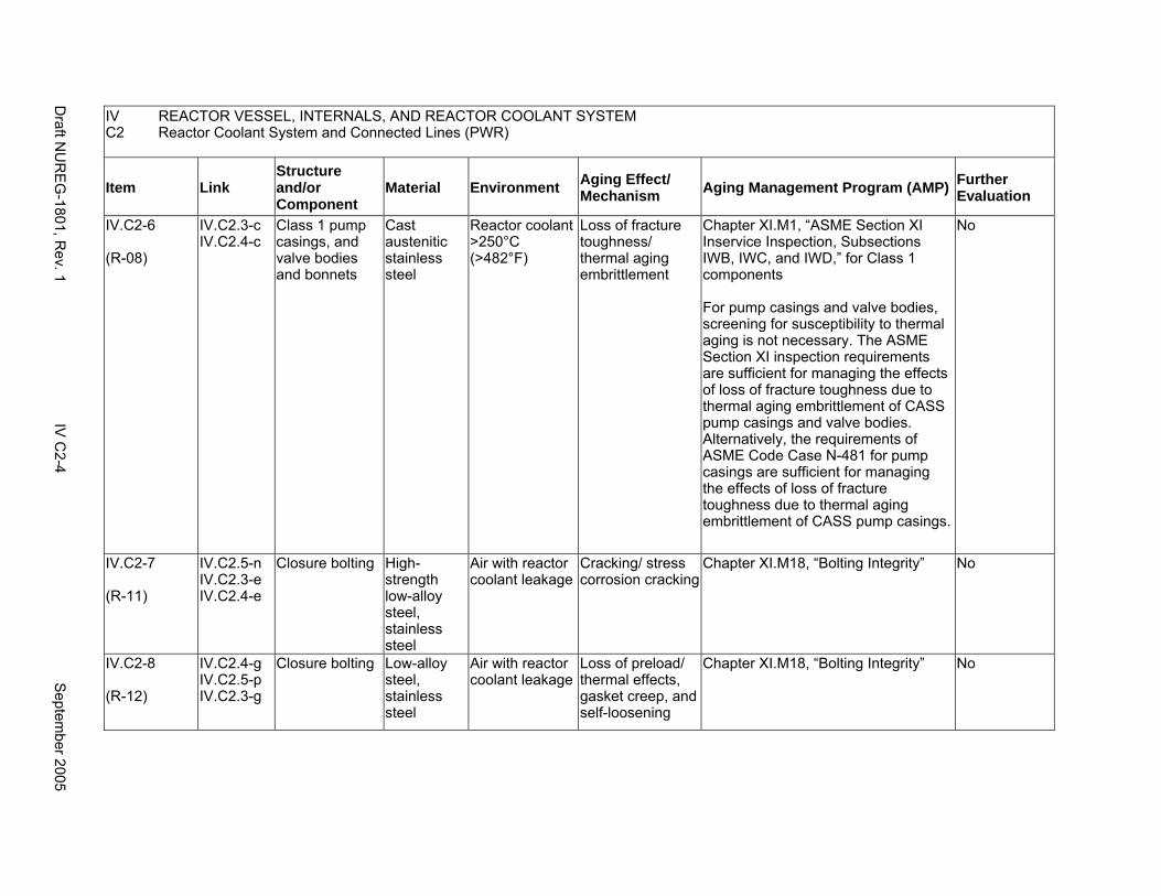
IV C2
REACTOR VESSEL, INTERNALS, AND REACTOR COOLANT SYSTEM Reactor Coolant System and Connected Lines (PWR)
Item Link Structure and/or Component
Material Environment Aging Effect/ Mechanism Aging Management Program (AMP) Further
Evaluation
IV.C2-6
(R-08)
IV.C2.3-c IV.C2.4-c
Class 1 pump casings, and valve bodies and bonnets
Cast austenitic stainless steel
Reactor coolant >250°C (>482°F)
Loss of fracture toughness/ thermal aging embrittlement
Chapter XI.M1, “ASME Section XI Inservice Inspection, Subsections IWB, IWC, and IWD,” for Class 1 components
For pump casings and valve bodies, screening for susceptibility to thermal aging is not necessary. The ASME Section XI inspection requirements are sufficient for managing the effects of loss of fracture toughness due to thermal aging embrittlement of CASS pump casings and valve bodies. Alternatively, the requirements of ASME Code Case N-481 for pump casings are sufficient for managing the effects of loss of fracture toughness due to thermal aging embrittlement of CASS pump casings.
No
IV.C2-7
(R-11)
IV.C2.5-n IV.C2.3-e IV.C2.4-e
Closure bolting High-strength low-alloy steel, stainless steel
Air with reactor coolant leakage
Cracking/ stress corrosion cracking
Chapter XI.M18, “Bolting Integrity” No
IV.C2-8
(R-12)
IV.C2.4-g IV.C2.5-p IV.C2.3-g
Closure bolting Low-alloy steel, stainless steel
Air with reactor coolant leakage
Loss of preload/ thermal effects, gasket creep, and self-loosening
Chapter XI.M18, “Bolting Integrity” No
Draft N
UR
EG
-1801, Rev. 1
IV C
2-4 S
eptember 2005
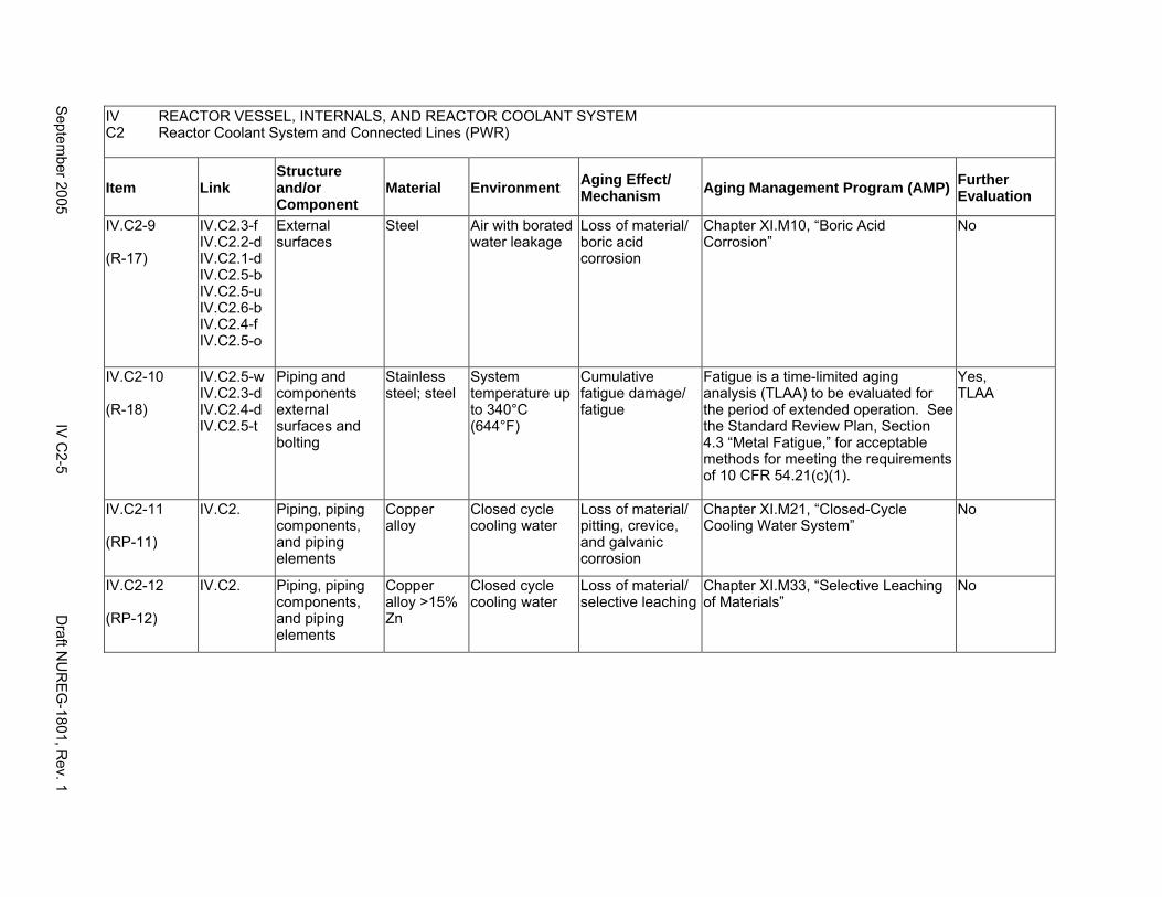
IV REACTOR VESSEL, INTERNALS, AND REACTOR COOLANT SYSTEM C2 Reactor Coolant System and Connected Lines (PWR)
Item Link Structure and/or Component
Material Environment Aging Effect/ Mechanism Aging Management Program (AMP) Further
Evaluation
IV.C2-9
(R-17)
IV.C2.3-f IV.C2.2-d IV.C2.1-d IV.C2.5-b IV.C2.5-u IV.C2.6-b IV.C2.4-f IV.C2.5-o
External surfaces
Steel Air with borated water leakage
Loss of material/ boric acid corrosion
Chapter XI.M10, “Boric Acid Corrosion”
No
IV.C2-10
(R-18)
IV.C2.5-w IV.C2.3-d IV.C2.4-d IV.C2.5-t
Piping and components external surfaces and bolting
Stainless steel; steel
System temperature up to 340°C (644°F)
Cumulative fatigue damage/ fatigue
Fatigue is a time-limited aging analysis (TLAA) to be evaluated for the period of extended operation. See the Standard Review Plan, Section 4.3 “Metal Fatigue,” for acceptable methods for meeting the requirements of 10 CFR 54.21(c)(1).
Yes, TLAA
IV.C2-11
(RP-11)
IV.C2. Piping, piping components, and piping elements
Copper alloy
Closed cycle cooling water
Loss of material/ pitting, crevice, and galvanic corrosion
Chapter XI.M21, “Closed-Cycle Cooling Water System”
No
IV.C2-12
(RP-12)
IV.C2. Piping, piping components, and piping elements
Copper alloy >15% Zn
Closed cycle cooling water
Loss of material/ selective leaching
Chapter XI.M33, “Selective Leaching of Materials”
No
Septem
ber 2005 IV
C2-5
Draft N
UR
EG
-1801, Rev. 1
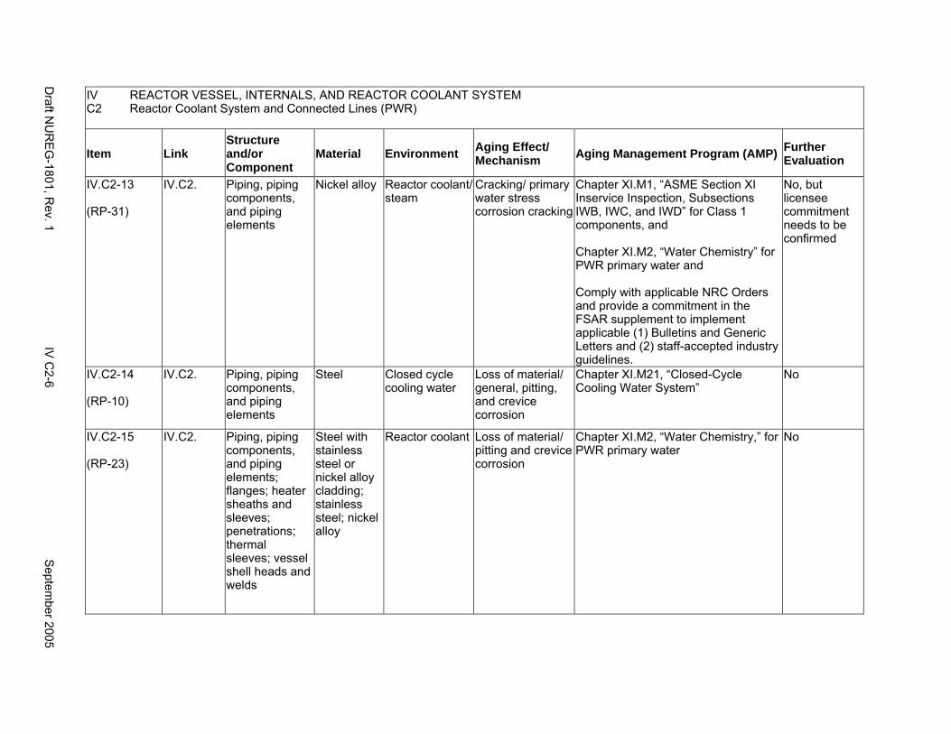
IV REACTOR VESSEL, INTERNALS, AND REACTOR COOLANT SYSTEM C2 Reactor Coolant System and Connected Lines (PWR)
Item Link Structure and/or Component
Material Environment Aging Effect/ Mechanism Aging Management Program (AMP) Further
Evaluation
IV.C2-13
(RP-31)
IV.C2. Piping, piping components, and piping elements
Nickel alloy Reactor coolant/ steam
Cracking/ primary water stress corrosion cracking
Chapter XI.M1, “ASME Section XI Inservice Inspection, Subsections IWB, IWC, and IWD” for Class 1 components, and
Chapter XI.M2, “Water Chemistry” for PWR primary water and
Comply with applicable NRC Orders and provide a commitment in the FSAR supplement to implement applicable (1) Bulletins and Generic Letters and (2) staff-accepted industry guidelines.
No, but licensee commitment needs to be confirmed
IV.C2-14
(RP-10)
IV.C2. Piping, piping components, and piping elements
Steel Closed cycle cooling water
Loss of material/ general, pitting, and crevice corrosion
Chapter XI.M21, “Closed-Cycle Cooling Water System”
No
IV.C2-15
(RP-23)
IV.C2. Piping, piping components, and piping elements; flanges; heater sheaths and sleeves; penetrations; thermal sleeves; vessel shell heads and welds
Steel with stainless steel or nickel alloy cladding; stainless steel; nickel alloy
Reactor coolant Loss of material/ pitting and crevice corrosion
Chapter XI.M2, “Water Chemistry,” for PWR primary water
No
Draft N
UR
EG
-1801, Rev. 1
IV C
2-6 S
eptember 2005
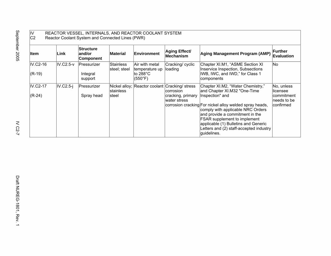
IV REACTOR VESSEL, INTERNALS, AND REACTOR COOLANT SYSTEM C2 Reactor Coolant System and Connected Lines (PWR)
Item Link Structure and/or Component
Material Environment Aging Effect/ Mechanism Aging Management Program (AMP) Further
Evaluation
IV.C2-16
(R-19)
IV.C2.5-v Pressurizer
Integral support
Stainless steel; steel
Air with metal temperature up to 288°C (550°F)
Cracking/ cyclic loading
Chapter XI.M1, “ASME Section XI Inservice Inspection, Subsections IWB, IWC, and IWD,” for Class 1 components
No
IV.C2-17
(R-24)
IV.C2.5-j Pressurizer
Spray head
Nickel alloy; stainless steel
Reactor coolant Cracking/ stress corrosion cracking, primary water stress corrosion cracking
Chapter XI.M2, “Water Chemistry,” and Chapter XI.M32 "One-Time Inspection" and
For nickel alloy welded spray heads, comply with applicable NRC Orders and provide a commitment in the FSAR supplement to implement applicable (1) Bulletins and Generic Letters and (2) staff-accepted industry guidelines.
No, unless licensee commitment needs to be confirmed
Septem
ber 2005 IV
C2-7
Draft N
UR
EG
-1801, Rev. 1
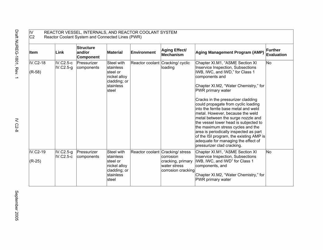
IV REACTOR VESSEL, INTERNALS, AND REACTOR COOLANT SYSTEM C2 Reactor Coolant System and Connected Lines (PWR)
Item Link Structure and/or Component
Material Environment Aging Effect/ Mechanism Aging Management Program (AMP) Further
Evaluation
IV.C2-18
(R-58)
IV.C2.5-c IV.C2.5-g
Pressurizer components
Steel with stainless steel or nickel alloy cladding; or stainless steel
Reactor coolant Cracking/ cyclic loading
Chapter XI.M1, “ASME Section XI Inservice Inspection, Subsections IWB, IWC, and IWD,” for Class 1 components and
Chapter XI.M2, “Water Chemistry,” for PWR primary water
Cracks in the pressurizer cladding could propagate from cyclic loading into the ferrite base metal and weld metal. However, because the weld metal between the surge nozzle and the vessel lower head is subjected to the maximum stress cycles and the area is periodically inspected as part of the ISI program, the existing AMP is adequate for managing the effect of pressurizer clad cracking.
No
IV.C2-19
(R-25)
IV.C2.5-g IV.C2.5-c
Pressurizer components
Steel with stainless steel or nickel alloy cladding; or stainless steel
Reactor coolant Cracking/ stress corrosion cracking, primary water stress corrosion cracking
Chapter XI.M1, “ASME Section XI Inservice Inspection, Subsections IWB, IWC, and IWD” for Class 1 components, and
Chapter XI.M2, “Water Chemistry,” for PWR primary water
No
Draft N
UR
EG
-1801, Rev. 1
IV C
2-8 S
eptember 2005
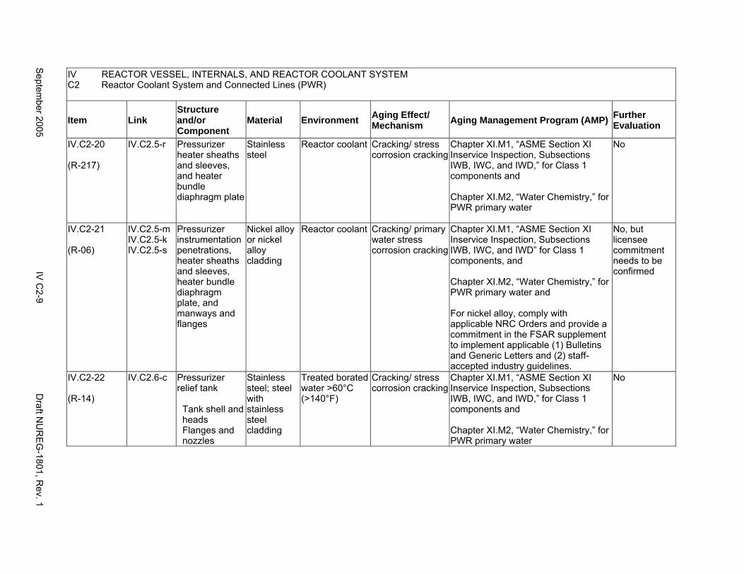
IV REACTOR VESSEL, INTERNALS, AND REACTOR COOLANT SYSTEM C2 Reactor Coolant System and Connected Lines (PWR)
Item Link Structure and/or Component
Material Environment Aging Effect/ Mechanism Aging Management Program (AMP) Further
Evaluation
IV.C2-20
(R-217)
IV.C2.5-r Pressurizer heater sheaths and sleeves, and heater bundle diaphragm plate
Stainless steel
Reactor coolant Cracking/ stress corrosion cracking
Chapter XI.M1, “ASME Section XI Inservice Inspection, Subsections IWB, IWC, and IWD,” for Class 1 components and
Chapter XI.M2, “Water Chemistry,” for PWR primary water
No
IV.C2-21
(R-06)
IV.C2.5-m IV.C2.5-k IV.C2.5-s
Pressurizer instrumentation penetrations, heater sheaths and sleeves, heater bundle diaphragm plate, and manways and flanges
Nickel alloy or nickel alloy cladding
Reactor coolant Cracking/ primary water stress corrosion cracking
Chapter XI.M1, “ASME Section XI Inservice Inspection, Subsections IWB, IWC, and IWD” for Class 1 components, and
Chapter XI.M2, “Water Chemistry,” for PWR primary water and
For nickel alloy, comply with applicable NRC Orders and provide a commitment in the FSAR supplement to implement applicable (1) Bulletins and Generic Letters and (2) staff-accepted industry guidelines.
No, but licensee commitment needs to be confirmed
IV.C2-22
(R-14)
IV.C2.6-c Pressurizer relief tank
Tank shell and heads Flanges and nozzles
Stainless steel; steel with stainless steel cladding
Treated borated water >60°C (>140°F)
Cracking/ stress corrosion cracking
Chapter XI.M1, “ASME Section XI Inservice Inspection, Subsections IWB, IWC, and IWD,” for Class 1 components and
Chapter XI.M2, “Water Chemistry,” for PWR primary water
No
Septem
ber 2005 IV
C2-9
Draft N
UR
EG
-1801, Rev. 1
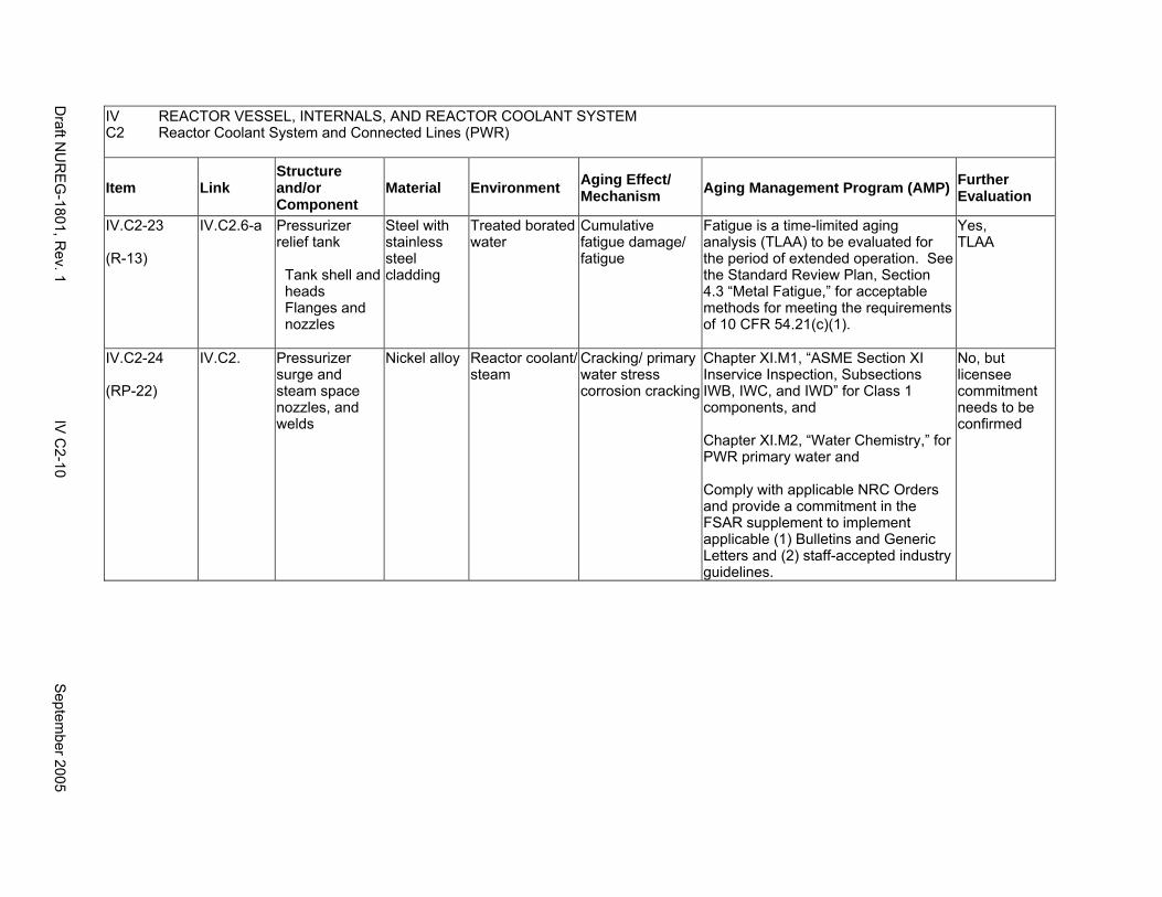
IV REACTOR VESSEL, INTERNALS, AND REACTOR COOLANT SYSTEM C2 Reactor Coolant System and Connected Lines (PWR)
Item Link Structure and/or Component
Material Environment Aging Effect/ Mechanism Aging Management Program (AMP) Further
Evaluation
IV.C2-23
(R-13)
IV.C2.6-a Pressurizer relief tank
Tank shell and heads Flanges and nozzles
Steel with stainless steel cladding
Treated borated water
Cumulative fatigue damage/ fatigue
Fatigue is a time-limited aging analysis (TLAA) to be evaluated for the period of extended operation. See the Standard Review Plan, Section 4.3 “Metal Fatigue,” for acceptable methods for meeting the requirements of 10 CFR 54.21(c)(1).
Yes, TLAA
IV.C2-24
(RP-22)
IV.C2. Pressurizer surge and steam space nozzles, and welds
Nickel alloy Reactor coolant/ steam
Cracking/ primary water stress corrosion cracking
Chapter XI.M1, “ASME Section XI Inservice Inspection, Subsections IWB, IWC, and IWD” for Class 1 components, and
Chapter XI.M2, “Water Chemistry,” for PWR primary water and
Comply with applicable NRC Orders and provide a commitment in the FSAR supplement to implement applicable (1) Bulletins and Generic Letters and (2) staff-accepted industry guidelines.
No, but licensee commitment needs to be confirmed
Draft N
UR
EG
-1801, Rev. 1
IV C
2-10 S
eptember 2005
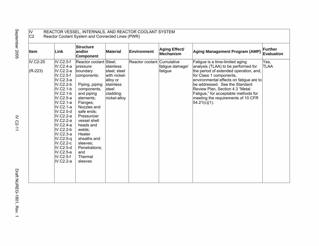
IV REACTOR VESSEL, INTERNALS, AND REACTOR COOLANT SYSTEM C2 Reactor Coolant System and Connected Lines (PWR)
Item Link Structure and/or Component
Material Environment Aging Effect/ Mechanism Aging Management Program (AMP) Further
Evaluation
IV.C2-25
(R-223)
IV.C2.5-f IV.C2.4-a IV.C2.2-a IV.C2.5-f IV.C2.3-a IV.C2.2-b IV.C2.1-b IV.C2.1-b IV.C2.5-a IV.C2.1-a IV.C2.1-a IV.C2.5-d IV.C2.2-a IV.C2.2-a IV.C2.4-a IV.C2.2-b IV.C2.3-a IV.C2.5-q IV.C2.2-c IV.C2.5-d IV.C2.5-e IV.C2.5-f IV.C2.2-a
Reactor coolant pressure boundary components:
Piping, piping components, and piping elements; Flanges; Nozzles and safe ends; Pressurizer vessel shell heads and welds; Heater sheaths and sleeves; Penetrations; and Thermal sleeves
Steel; stainless steel; steel with nickel-alloy or stainless steel cladding; nickel-alloy
Reactor coolant Cumulative fatigue damage/ fatigue
Fatigue is a time-limited aging analysis (TLAA) to be performed for the period of extended operation, and, for Class 1 components, environmental effects on fatigue are to be addressed. See the Standard Review Plan, Section 4.3 “Metal Fatigue,” for acceptable methods for meeting the requirements of 10 CFR 54.21(c)(1).
Yes, TLAA
Septem
ber 2005 IV
C2-11
Draft N
UR
EG
-1801, Rev. 1
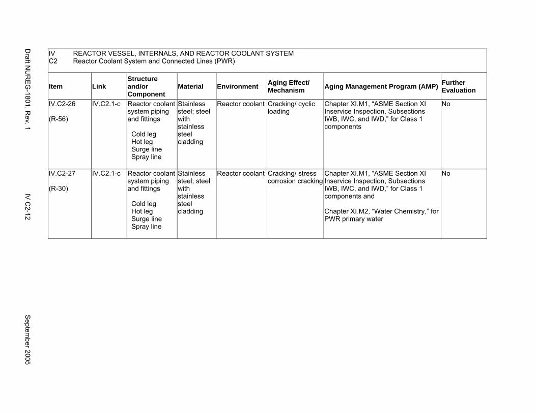
IV REACTOR VESSEL, INTERNALS, AND REACTOR COOLANT SYSTEM C2 Reactor Coolant System and Connected Lines (PWR)
Item Link Structure and/or Component
Material Environment Aging Effect/ Mechanism Aging Management Program (AMP) Further
Evaluation
IV.C2-26
(R-56)
IV.C2.1-c Reactor coolant system piping and fittings
Cold leg Hot leg Surge line Spray line
Stainless steel; steel with stainless steel cladding
Reactor coolant Cracking/ cyclic loading
Chapter XI.M1, “ASME Section XI Inservice Inspection, Subsections IWB, IWC, and IWD,” for Class 1 components
No
IV.C2-27
(R-30)
IV.C2.1-c Reactor coolant system piping and fittings
Cold leg Hot leg Surge line Spray line
Stainless steel; steel with stainless steel cladding
Reactor coolant Cracking/ stress corrosion cracking
Chapter XI.M1, “ASME Section XI Inservice Inspection, Subsections IWB, IWC, and IWD,” for Class 1 components and
Chapter XI.M2, “Water Chemistry,” for PWR primary water
No
Draft N
UR
EG
-1801, Rev. 1
IV C
2-12 S
eptember 2005
D1. STEAM GENERATOR (RECIRCULATING)
Systems, Structures, and Components
This section addresses the recirculating-type steam generators, as found in Westinghouse and Combustion Engineering pressurized water reactors (PWRs), including all internal components and water/steam nozzles and safe ends. Based on Regulatory Guide 1.26, “Quality Group Classifications and Standards for Water-, Steam-, and Radioactive-Waste-Containing Components of Nuclear Power Plants,” the primary water side (tube side) of the steam generator is governed by Group A Quality Standards, and the secondary water side is governed by Group B Quality Standards.
Common miscellaneous material/environment combinations where aging effects are not expected to degrade the ability of the structure or component to perform its intended function for the extended period of operation are included in IV.E.
System Interfaces
The systems that interface with the steam generators include the reactor coolant system and connected lines (IV.C2), the containment isolation components (V.C), the main steam system (VIII.B1), the feedwater system (VIII.D1), the steam generator blowdown system (VIII.F), and the auxiliary feedwater system (VIII.G).
September 2005 IV D1-1 Draft NUREG-1801, Rev. 1
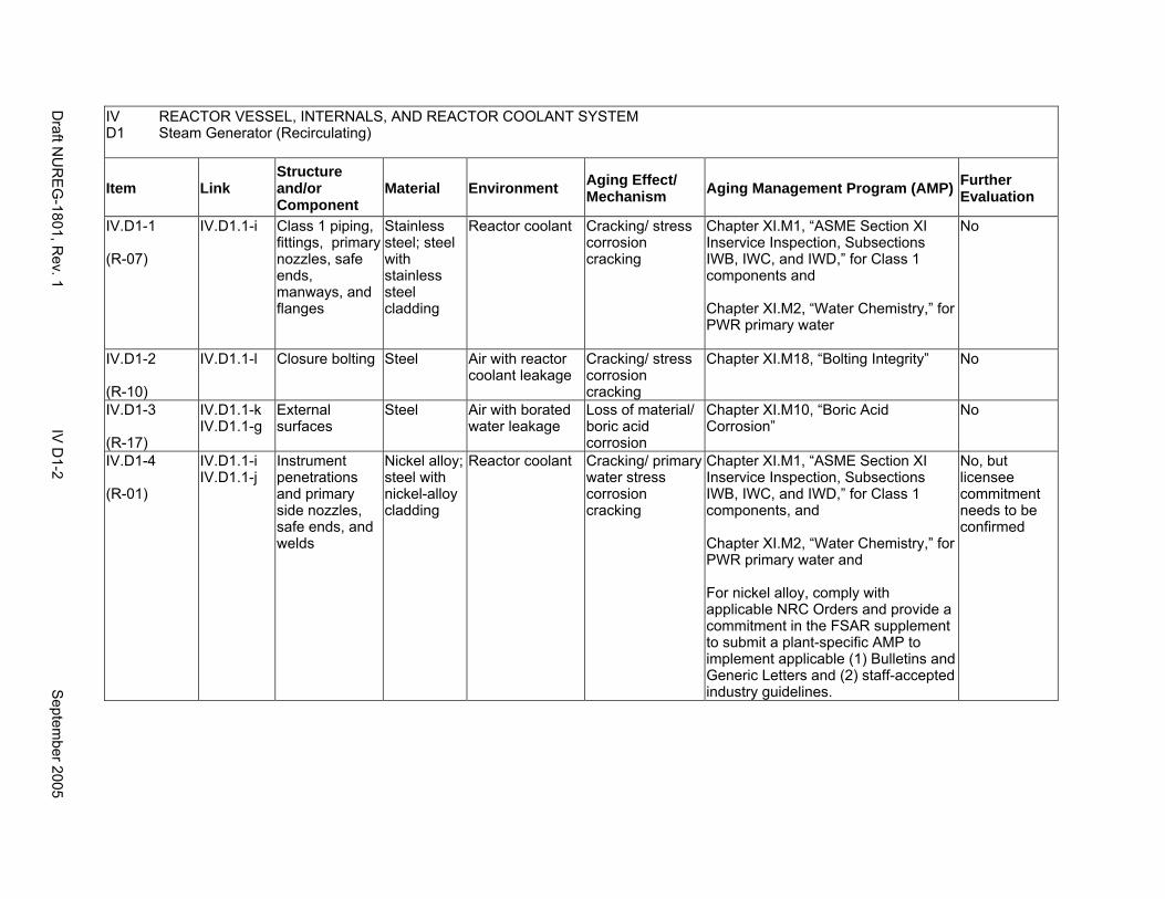
IV D1
REACTOR VESSEL, INTERNALS, AND REACTOR COOLANT SYSTEM Steam Generator (Recirculating)
Item Link Structure and/or Component
Material Environment Aging Effect/ Mechanism Aging Management Program (AMP) Further
Evaluation
IV.D1-1
(R-07)
IV.D1.1-i Class 1 piping, fittings, primary nozzles, safe ends, manways, and flanges
Stainless steel; steel with stainless steel cladding
Reactor coolant Cracking/ stress corrosion cracking
Chapter XI.M1, “ASME Section XI Inservice Inspection, Subsections IWB, IWC, and IWD,” for Class 1 components and
Chapter XI.M2, “Water Chemistry,” for PWR primary water
No
IV.D1-2
(R-10)
IV.D1.1-l Closure bolting Steel Air with reactor coolant leakage
Cracking/ stress corrosion cracking
Chapter XI.M18, “Bolting Integrity” No
IV.D1-3
(R-17)
IV.D1.1-k IV.D1.1-g
External surfaces
Steel Air with borated water leakage
Loss of material/ boric acid corrosion
Chapter XI.M10, “Boric Acid Corrosion”
No
IV.D1-4
(R-01)
IV.D1.1-i IV.D1.1-j
Instrument penetrations and primary side nozzles, safe ends, and welds
Nickel alloy; steel with nickel-alloy cladding
Reactor coolant Cracking/ primary water stress corrosion cracking
Chapter XI.M1, “ASME Section XI Inservice Inspection, Subsections IWB, IWC, and IWD,” for Class 1 components, and
Chapter XI.M2, “Water Chemistry,” for PWR primary water and
For nickel alloy, comply with applicable NRC Orders and provide a commitment in the FSAR supplement to submit a plant-specific AMP to implement applicable (1) Bulletins and Generic Letters and (2) staff-accepted industry guidelines.
No, but licensee commitment needs to be confirmed
Draft N
UR
EG
-1801, Rev. 1
IV D
1-2 S
eptember 2005
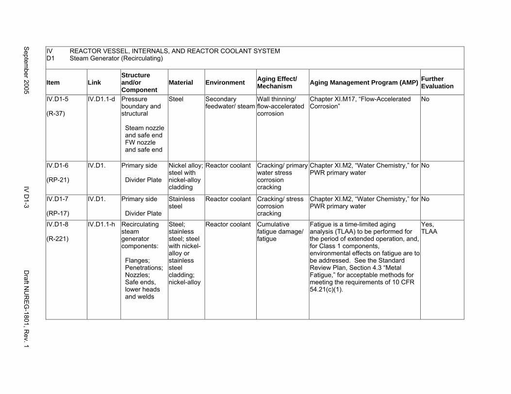
IV D1
REACTOR VESSEL, INTERNALS, AND REACTOR COOLANT SYSTEM Steam Generator (Recirculating)
Item Link Structure and/or Component
Material Environment Aging Effect/ Mechanism Aging Management Program (AMP) Further
Evaluation
IV.D1-5
(R-37)
IV.D1.1-d Pressure boundary and structural
Steam nozzle and safe end FW nozzle and safe end
Steel Secondary feedwater/ steam
Wall thinning/ flow-accelerated corrosion
Chapter XI.M17, “Flow-Accelerated Corrosion”
No
IV.D1-6
(RP-21)
IV.D1. Primary side
Divider Plate
Nickel alloy; steel with nickel-alloy cladding
Reactor coolant Cracking/ primary water stress corrosion cracking
Chapter XI.M2, “Water Chemistry,” for PWR primary water
No
IV.D1-7
(RP-17)
IV.D1. Primary side
Divider Plate
Stainless steel
Reactor coolant Cracking/ stress corrosion cracking
Chapter XI.M2, “Water Chemistry,” for PWR primary water
No
IV.D1-8
(R-221)
IV.D1.1-h Recirculating steam generator components:
Flanges; Penetrations; Nozzles; Safe ends, lower heads and welds
Steel; stainless steel; steel with nickel-alloy or stainless steel cladding; nickel-alloy
Reactor coolant Cumulative fatigue damage/ fatigue
Fatigue is a time-limited aging analysis (TLAA) to be performed for the period of extended operation, and, for Class 1 components, environmental effects on fatigue are to be addressed. See the Standard Review Plan, Section 4.3 “Metal Fatigue,” for acceptable methods for meeting the requirements of 10 CFR 54.21(c)(1).
Yes, TLAA
Septem
ber 2005 IV
D1-3
Draft N
UR
EG
-1801, Rev. 1
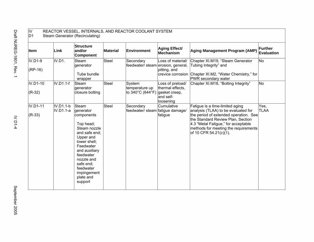
IV REACTOR VESSEL, INTERNALS, AND REACTOR COOLANT SYSTEM D1 Steam Generator (Recirculating)
Item Link Structure and/or Component
Material Environment Aging Effect/ Mechanism Aging Management Program (AMP) Further
Evaluation
IV.D1-9
(RP-16)
IV.D1. Steam generator
Tube bundle wrapper
Steel Secondary feedwater/ steam
Loss of material/ erosion, general, pitting, and crevice corrosion
Chapter XI.M19, “Steam Generator Tubing Integrity” and
Chapter XI.M2, “Water Chemistry,” for PWR secondary water
No
IV.D1-10
(R-32)
IV.D1.1-f Steam generator closure bolting
Steel System temperature up to 340°C (644°F)
Loss of preload/ thermal effects, gasket creep, and self-loosening
Chapter XI.M18, “Bolting Integrity” No
IV.D1-11
(R-33)
IV.D1.1-b IV.D1.1-a
Steam generator components
Top head; Steam nozzle and safe end; Upper and lower shell; Feedwater and auxiliary feedwater nozzle and safe end; feedwater impingement plate and support
Steel Secondary feedwater/ steam
Cumulative fatigue damage/ fatigue
Fatigue is a time-limited aging analysis (TLAA) to be evaluated for the period of extended operation. See the Standard Review Plan, Section 4.3 “Metal Fatigue,” for acceptable methods for meeting the requirements of 10 CFR 54.21(c)(1).
Yes, TLAA
Draft N
UR
EG
-1801, Rev. 1
IV D
1-4 S
eptember 2005
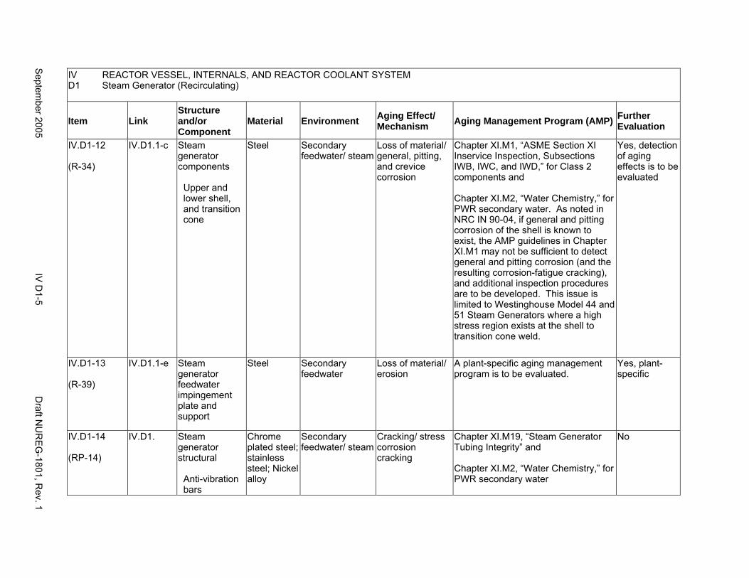
IV REACTOR VESSEL, INTERNALS, AND REACTOR COOLANT SYSTEM D1 Steam Generator (Recirculating)
Item Link Structure and/or Component
Material Environment Aging Effect/ Mechanism Aging Management Program (AMP) Further
Evaluation
IV.D1-12
(R-34)
IV.D1.1-c Steam generator components
Upper and lower shell, and transition cone
Steel Secondary feedwater/ steam
Loss of material/ general, pitting, and crevice corrosion
Chapter XI.M1, “ASME Section XI Inservice Inspection, Subsections IWB, IWC, and IWD,” for Class 2 components and
Chapter XI.M2, “Water Chemistry,” for PWR secondary water. As noted in NRC IN 90-04, if general and pitting corrosion of the shell is known to exist, the AMP guidelines in Chapter XI.M1 may not be sufficient to detect general and pitting corrosion (and the resulting corrosion-fatigue cracking), and additional inspection procedures are to be developed. This issue is limited to Westinghouse Model 44 and 51 Steam Generators where a high stress region exists at the shell to transition cone weld.
Yes, detection of aging effects is to be evaluated
IV.D1-13
(R-39)
IV.D1.1-e Steam generator feedwater impingement plate and support
Steel Secondary feedwater
Loss of material/ erosion
A plant-specific aging management program is to be evaluated.
Yes, plant-specific
IV.D1-14
(RP-14)
IV.D1. Steam generator structural
Anti-vibration bars
Chrome plated steel; stainless steel; Nickel alloy
Secondary feedwater/ steam
Cracking/ stress corrosion cracking
Chapter XI.M19, “Steam Generator Tubing Integrity” and
Chapter XI.M2, “Water Chemistry,” for PWR secondary water
No
Septem
ber 2005 IV
D1-5
Draft N
UR
EG
-1801, Rev. 1
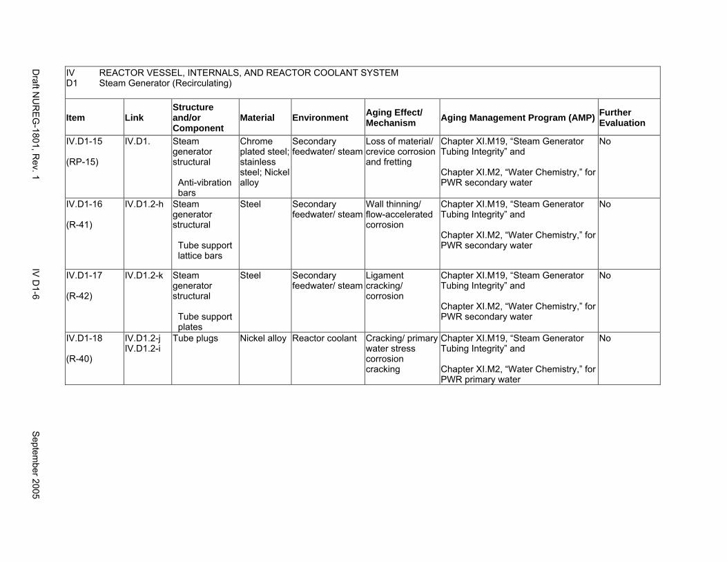
IV REACTOR VESSEL, INTERNALS, AND REACTOR COOLANT SYSTEM D1 Steam Generator (Recirculating)
Item Link Structure and/or Component
Material Environment Aging Effect/ Mechanism Aging Management Program (AMP) Further
Evaluation
IV.D1-15
(RP-15)
IV.D1. Steam generator structural
Anti-vibration bars
Chrome plated steel; stainless steel; Nickel alloy
Secondary feedwater/ steam
Loss of material/ crevice corrosion and fretting
Chapter XI.M19, “Steam Generator Tubing Integrity” and
Chapter XI.M2, “Water Chemistry,” for PWR secondary water
No
IV.D1-16
(R-41)
IV.D1.2-h Steam generator structural
Tube support lattice bars
Steel Secondary feedwater/ steam
Wall thinning/ flow-accelerated corrosion
Chapter XI.M19, “Steam Generator Tubing Integrity” and
Chapter XI.M2, “Water Chemistry,” for PWR secondary water
No
IV.D1-17
(R-42)
IV.D1.2-k Steam generator structural
Tube support plates
Steel Secondary feedwater/ steam
Ligament cracking/ corrosion
Chapter XI.M19, “Steam Generator Tubing Integrity” and
Chapter XI.M2, “Water Chemistry,” for PWR secondary water
No
IV.D1-18
(R-40)
IV.D1.2-j IV.D1.2-i
Tube plugs Nickel alloy Reactor coolant Cracking/ primary water stress corrosion cracking
Chapter XI.M19, “Steam Generator Tubing Integrity” and
Chapter XI.M2, “Water Chemistry,” for PWR primary water
No
Draft N
UR
EG
-1801, Rev. 1
IV D
1-6 S
eptember 2005
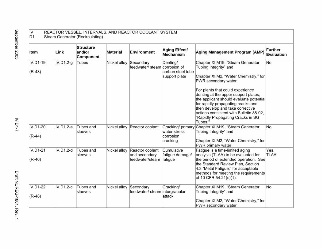
IV REACTOR VESSEL, INTERNALS, AND REACTOR COOLANT SYSTEM D1 Steam Generator (Recirculating)
Item Link Structure and/or Component
Material Environment Aging Effect/ Mechanism Aging Management Program (AMP) Further
Evaluation
IV.D1-19
(R-43)
IV.D1.2-g Tubes Nickel alloy Secondary feedwater/ steam
Denting/ corrosion of carbon steel tube support plate
Chapter XI.M19, “Steam Generator Tubing Integrity” and
Chapter XI.M2, “Water Chemistry,” for PWR secondary water.
For plants that could experience denting at the upper support plates, the applicant should evaluate potential for rapidly propagating cracks and then develop and take corrective actions consistent with Bulletin 88-02, “Rapidly Propagating Cracks in SG Tubes."
No
IV.D1-20
(R-44)
IV.D1.2-a Tubes and sleeves
Nickel alloy Reactor coolant Cracking/ primary water stress corrosion cracking
Chapter XI.M19, “Steam Generator Tubing Integrity” and
Chapter XI.M2, “Water Chemistry,” for PWR primary water
No
IV.D1-21
(R-46)
IV.D1.2-d Tubes and sleeves
Nickel alloy Reactor coolant and secondary feedwater/steam
Cumulative fatigue damage/ fatigue
Fatigue is a time-limited aging analysis (TLAA) to be evaluated for the period of extended operation. See the Standard Review Plan, Section 4.3 “Metal Fatigue,” for acceptable methods for meeting the requirements of 10 CFR 54.21(c)(1).
Yes, TLAA
IV.D1-22
(R-48)
IV.D1.2-c Tubes and sleeves
Nickel alloy Secondary feedwater/ steam
Cracking/ intergranular attack
Chapter XI.M19, “Steam Generator Tubing Integrity” and
Chapter XI.M2, “Water Chemistry,” for PWR secondary water
No
Septem
ber 2005 IV
D1-7
Draft N
UR
EG
-1801, Rev. 1
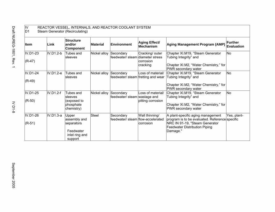
IV REACTOR VESSEL, INTERNALS, AND REACTOR COOLANT SYSTEM D1 Steam Generator (Recirculating)
Item Link Structure and/or Component
Material Environment Aging Effect/ Mechanism Aging Management Program (AMP) Further
Evaluation
IV.D1-23
(R-47)
IV.D1.2-b Tubes and sleeves
Nickel alloy Secondary feedwater/ steam
Cracking/ outer diameter stress corrosion cracking
Chapter XI.M19, “Steam Generator Tubing Integrity” and
Chapter XI.M2, “Water Chemistry,” for PWR secondary water
No
IV.D1-24
(R-49)
IV.D1.2-e Tubes and sleeves
Nickel alloy Secondary feedwater/ steam
Loss of material/ fretting and wear
Chapter XI.M19, “Steam Generator Tubing Integrity” and
Chapter XI.M2, “Water Chemistry,” for PWR secondary water
No
IV.D1-25
(R-50)
IV.D1.2-f Tubes and sleeves (exposed to phosphate chemistry)
Nickel alloy Secondary feedwater/ steam
Loss of material/ wastage and pitting corrosion
Chapter XI.M19, “Steam Generator Tubing Integrity” and
Chapter XI.M2, “Water Chemistry,” for PWR secondary water
No
IV.D1-26
(R-51)
IV.D1.3-a Upper assembly and separators
Feedwater inlet ring and support
Steel Secondary feedwater/ steam
Wall thinning/ flow-accelerated corrosion
A plant-specific aging management program is to be evaluated. Reference NRC IN 91-19, "Steam Generator Feedwater Distribution Piping Damage."
Yes, plant-specific
Draft N
UR
EG
-1801, Rev. 1
IV D
1-8 S
eptember 2005
D2. STEAM GENERATOR (ONCE-THROUGH)
Systems, Structures, and Components
This section addresses the once-through type steam generators, as found in Babcock & Wilcox pressurized water reactors (PWRs), including all internal components and water/steam nozzles and safe ends. Based on Regulatory Guide 1.26, “Quality Group Classifications and Standards for Water-, Steam-, and Radioactive-Waste-Containing Components of Nuclear Power Plants,” the primary water side (tube side) of the steam generator is governed by Group A Quality Standards, and the secondary water side is governed by Group B Quality Standards.
Common miscellaneous material/environment combinations where aging effects are not expected to degrade the ability of the structure or component to perform its intended function for the extended period of operation are included in IV.E.
System Interfaces
The systems that interface with the steam generators include the reactor coolant system and connected lines (IV.C2), the main steam system (VIII.B1), the feedwater system (VIII.D1), the steam generator blowdown system (VIII.F), and the auxiliary feedwater system (VIII.G).
September 2005 IV D2-1 Draft NUREG-1801, Rev. 1
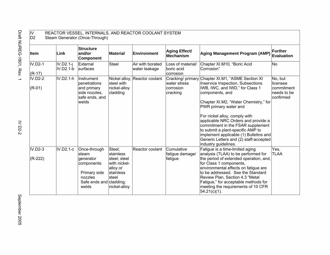
IV D2
REACTOR VESSEL, INTERNALS, AND REACTOR COOLANT SYSTEM Steam Generator (Once-Through)
Item Link Structure and/or Component
Material Environment Aging Effect/ Mechanism Aging Management Program (AMP) Further
Evaluation
IV.D2-1
(R-17)
IV.D2.1-j IV.D2.1-b
External surfaces
Steel Air with borated water leakage
Loss of material/ boric acid corrosion
Chapter XI.M10, “Boric Acid Corrosion”
No
IV.D2-2
(R-01)
IV.D2.1-h Instrument penetrations and primary side nozzles, safe ends, and welds
Nickel alloy; steel with nickel-alloy cladding
Reactor coolant Cracking/ primary water stress corrosion cracking
Chapter XI.M1, “ASME Section XI Inservice Inspection, Subsections IWB, IWC, and IWD,” for Class 1 components, and
Chapter XI.M2, “Water Chemistry,” for PWR primary water and
For nickel alloy, comply with applicable NRC Orders and provide a commitment in the FSAR supplement to submit a plant-specific AMP to implement applicable (1) Bulletins and Generic Letters and (2) staff-accepted industry guidelines.
No, but licensee commitment needs to be confirmed
IV.D2-3
(R-222)
IV.D2.1-c Once-through steam generator components:
Primary side nozzles Safe ends and welds
Steel; stainless steel; steel with nickel-alloy or stainless steel cladding; nickel-alloy
Reactor coolant Cumulative fatigue damage/ fatigue
Fatigue is a time-limited aging analysis (TLAA) to be performed for the period of extended operation, and, for Class 1 components, environmental effects on fatigue are to be addressed. See the Standard Review Plan, Section 4.3 “Metal Fatigue,” for acceptable methods for meeting the requirements of 10 CFR 54.21(c)(1).
Yes, TLAA
Draft N
UR
EG
-1801, Rev. 1
IV D
2-2 S
eptember 2005
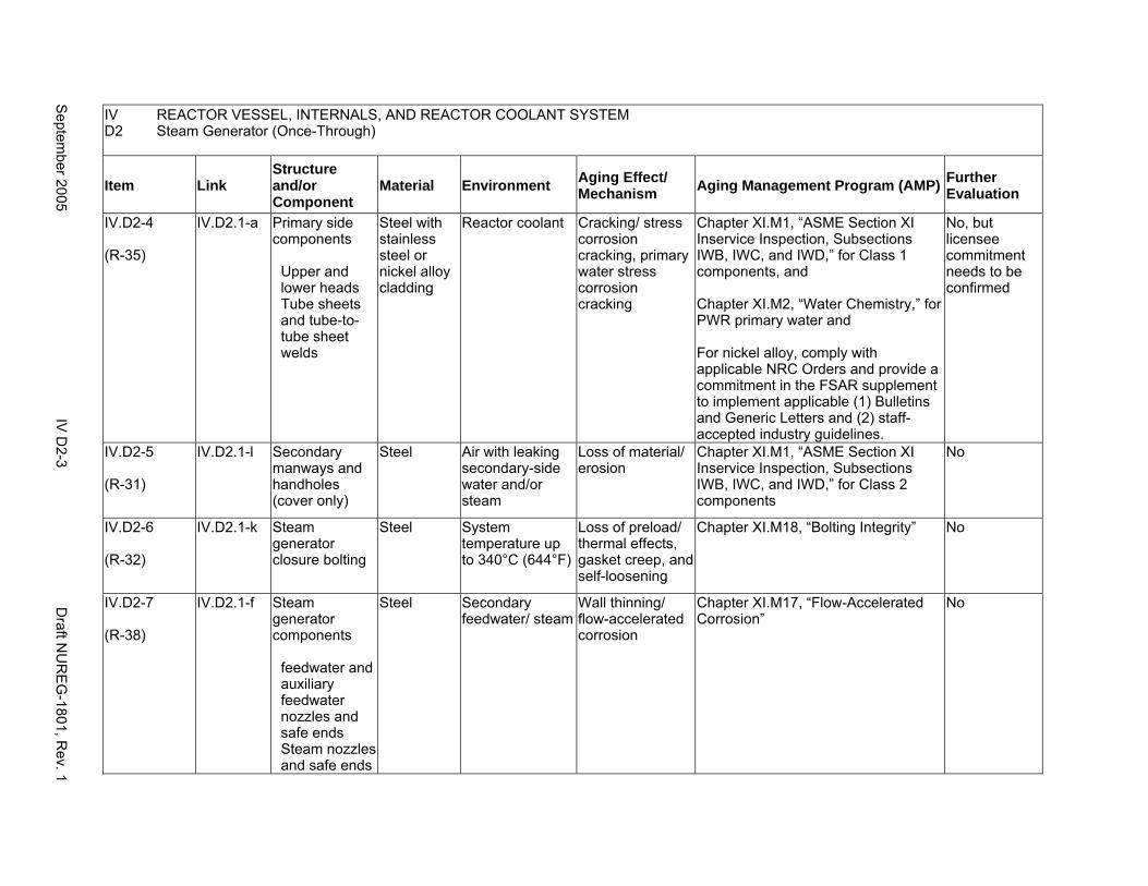
IV D2
REACTOR VESSEL, INTERNALS, AND REACTOR COOLANT SYSTEM Steam Generator (Once-Through)
Item Link Structure and/or Component
Material Environment Aging Effect/ Mechanism Aging Management Program (AMP) Further
Evaluation
IV.D2-4
(R-35)
IV.D2.1-a Primary side components
Upper and lower heads Tube sheets and tube-totube sheet welds
Steel with stainless steel or nickel alloy cladding
Reactor coolant Cracking/ stress corrosion cracking, primary water stress corrosion cracking
Chapter XI.M1, “ASME Section XI Inservice Inspection, Subsections IWB, IWC, and IWD,” for Class 1 components, and
Chapter XI.M2, “Water Chemistry,” for PWR primary water and
For nickel alloy, comply with applicable NRC Orders and provide a commitment in the FSAR supplement to implement applicable (1) Bulletins and Generic Letters and (2) staff-accepted industry guidelines.
No, but licensee commitment needs to be confirmed
IV.D2-5
(R-31)
IV.D2.1-l Secondary manways and handholes (cover only)
Steel Air with leaking secondary-side water and/or steam
Loss of material/ erosion
Chapter XI.M1, “ASME Section XI Inservice Inspection, Subsections IWB, IWC, and IWD,” for Class 2 components
No
IV.D2-6
(R-32)
IV.D2.1-k Steam generator closure bolting
Steel System temperature up to 340°C (644°F)
Loss of preload/ thermal effects, gasket creep, and self-loosening
Chapter XI.M18, “Bolting Integrity” No
IV.D2-7
(R-38)
IV.D2.1-f Steam generator components
feedwater and auxiliary feedwater nozzles and safe ends Steam nozzles and safe ends
Steel Secondary feedwater/ steam
Wall thinning/ flow-accelerated corrosion
Chapter XI.M17, “Flow-Accelerated Corrosion”
No
Septem
ber 2005 IV
D2-3
Draft N
UR
EG
-1801, Rev. 1
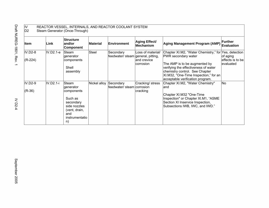
IV REACTOR VESSEL, INTERNALS, AND REACTOR COOLANT SYSTEM D2 Steam Generator (Once-Through)
Item Link Structure and/or Component
Material Environment Aging Effect/ Mechanism Aging Management Program (AMP) Further
Evaluation
IV.D2-8
(R-224)
IV.D2.1-e Steam generator components
Shell assembly
Steel Secondary feedwater/ steam
Loss of material/ general, pitting, and crevice corrosion
Chapter XI.M2, “Water Chemistry,” for PWR secondary water
The AMP is to be augmented by verifying the effectiveness of water chemistry control. See Chapter XI.M32, “One-Time Inspection,” for an acceptable verification program.
Yes, detection of aging effects is to be evaluated
IV.D2-9
(R-36)
IV.D2.1-i Steam generator components
Such as secondary side nozzles (vent, drain, and instrumentatio n)
Nickel alloy Secondary feedwater/ steam
Cracking/ stress corrosion cracking
Chapter XI.M2, "Water Chemistry" and
Chapter XI.M32 "One-Time Inspection" or Chapter XI.M1, “ASME Section XI Inservice Inspection, Subsections IWB, IWC, and IWD.”
No
Draft N
UR
EG
-1801, Rev. 1
IV D
2-4 S
eptember 2005
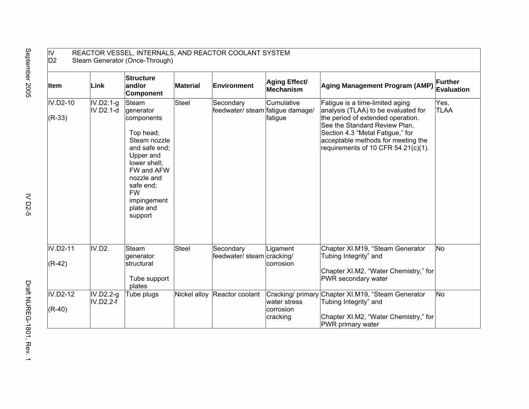
IV REACTOR VESSEL, INTERNALS, AND REACTOR COOLANT SYSTEM D2 Steam Generator (Once-Through)
Item Link Structure and/or Component
Material Environment Aging Effect/ Mechanism Aging Management Program (AMP) Further
Evaluation
IV.D2-10
(R-33)
IV.D2.1-g IV.D2.1-d
Steam generator components
Top head; Steam nozzle and safe end; Upper and lower shell; FW and AFW nozzle and safe end; FW impingement plate and support
Steel Secondary feedwater/ steam
Cumulative fatigue damage/ fatigue
Fatigue is a time-limited aging analysis (TLAA) to be evaluated for the period of extended operation. See the Standard Review Plan, Section 4.3 “Metal Fatigue,” for acceptable methods for meeting the requirements of 10 CFR 54.21(c)(1).
Yes, TLAA
IV.D2-11
(R-42)
IV.D2. Steam generator structural
Tube support plates
Steel Secondary feedwater/ steam
Ligament cracking/ corrosion
Chapter XI.M19, “Steam Generator Tubing Integrity” and
Chapter XI.M2, “Water Chemistry,” for PWR secondary water
No
IV.D2-12
(R-40)
IV.D2.2-g IV.D2.2-f
Tube plugs Nickel alloy Reactor coolant Cracking/ primary water stress corrosion cracking
Chapter XI.M19, “Steam Generator Tubing Integrity” and
Chapter XI.M2, “Water Chemistry,” for PWR primary water
No
Septem
ber 2005 IV
D2-5
Draft N
UR
EG
-1801, Rev. 1
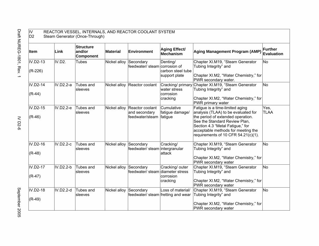
IV REACTOR VESSEL, INTERNALS, AND REACTOR COOLANT SYSTEM D2 Steam Generator (Once-Through)
Item Link Structure and/or Component
Material Environment Aging Effect/ Mechanism Aging Management Program (AMP) Further
Evaluation
IV.D2-13
(R-226)
IV.D2. Tubes Nickel alloy Secondary feedwater/ steam
Denting/ corrosion of carbon steel tube support plate
Chapter XI.M19, “Steam Generator Tubing Integrity” and
Chapter XI.M2, “Water Chemistry,” for PWR secondary water.
No
IV.D2-14
(R-44)
IV.D2.2-a Tubes and sleeves
Nickel alloy Reactor coolant Cracking/ primary water stress corrosion cracking
Chapter XI.M19, “Steam Generator Tubing Integrity” and
Chapter XI.M2, “Water Chemistry,” for PWR primary water
No
IV.D2-15
(R-46)
IV.D2.2-e Tubes and sleeves
Nickel alloy Reactor coolant and secondary feedwater/steam
Cumulative fatigue damage/ fatigue
Fatigue is a time-limited aging analysis (TLAA) to be evaluated for the period of extended operation. See the Standard Review Plan, Section 4.3 “Metal Fatigue,” for acceptable methods for meeting the requirements of 10 CFR 54.21(c)(1).
Yes, TLAA
IV.D2-16
(R-48)
IV.D2.2-c Tubes and sleeves
Nickel alloy Secondary feedwater/ steam
Cracking/ intergranular attack
Chapter XI.M19, “Steam Generator Tubing Integrity” and
Chapter XI.M2, “Water Chemistry,” for PWR secondary water
No
IV.D2-17
(R-47)
IV.D2.2-b Tubes and sleeves
Nickel alloy Secondary feedwater/ steam
Cracking/ outer diameter stress corrosion cracking
Chapter XI.M19, “Steam Generator Tubing Integrity” and
Chapter XI.M2, “Water Chemistry,” for PWR secondary water
No
IV.D2-18
(R-49)
IV.D2.2-d Tubes and sleeves
Nickel alloy Secondary feedwater/ steam
Loss of material/ fretting and wear
Chapter XI.M19, “Steam Generator Tubing Integrity” and
Chapter XI.M2, “Water Chemistry,” for PWR secondary water
No
Draft N
UR
EG
-1801, Rev. 1
IV D
2-6 S
eptember 2005
E. COMMON MISCELLANEOUS MATERIAL/ENVIRONMENT COMBINATIONS
Systems, Structures, and Components
This section addresses the aging management programs for miscellaneous material/environment combinations which may be found throughout the reactor vessel, internals and reactor coolant system’s structures and components. For the material/environment combinations in this part, aging effects are not expected to degrade the ability of the structure or component to perform its intended function for the extended period of operation, therefore, no resulting aging management programs for these structures and components are required.
System Interfaces
The structures and components covered in this section belong to the engineered safety features in PWRs and BWRs. (For example, see System Interfaces in V.A to V.D2 for details.)
September 2005 IV E-1 Draft NUREG-1801, Rev. 1
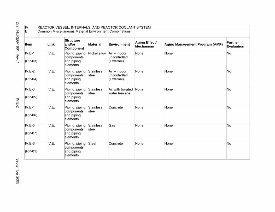
IV REACTOR VESSEL, INTERNALS, AND REACTOR COOLANT SYSTEM E Common Miscellaneous Material Environment Combinations
Item Link Structure and/or Component
Material Environment Aging Effect/ Mechanism Aging Management Program (AMP) Further
Evaluation
IV.E-1
(RP-03)
IV.E. Piping, piping components, and piping elements
Nickel alloy Air – indoor uncontrolled (External)
None None No
IV.E-2
(RP-04)
IV.E. Piping, piping components, and piping elements
Stainless steel
Air – indoor uncontrolled (External)
None None No
IV.E-3
(RP-05)
IV.E. Piping, piping components, and piping elements
Stainless steel
Air with borated water leakage
None None No
IV.E-4
(RP-06)
IV.E. Piping, piping components, and piping elements
Stainless steel
Concrete None None No
IV.E-5
(RP-07)
IV.E. Piping, piping components, and piping elements
Stainless steel
Gas None None No
IV.E-6
(RP-01)
IV.E. Piping, piping components, and piping elements
Steel Concrete None None No
Draft N
UR
EG
-1801, Rev. 1
IV E
-2 S
eptember 2005
CHAPTER V
ENGINEERED SAFETY FEATURES
September 2005 V-i Draft NUREG-1801, Rev. 1

This Page Intentionally Left Blank
Draft NUREG-1801, Rev. 1 V-ii September 2005
MAJOR PLANT SECTIONS
A. Containment Spray System (Pressurized Water Reactors)
B. Standby Gas Treatment System (Boiling Water Reactors)
C. Containment Isolation Components
D1. Emergency Core Cooling System (Pressurized Water Reactors)
D2. Emergency Core Cooling System (Boiling Water Reactors)
E. External Surfaces of Components and Miscellaneous Bolting
F. Common Miscellaneous Material/Environment Combinations
September 2005 V-iii Draft NUREG-1801, Rev. 1

This Page Intentionally Left Blank
Draft NUREG-1801, Rev. 1 V-iv September 2005
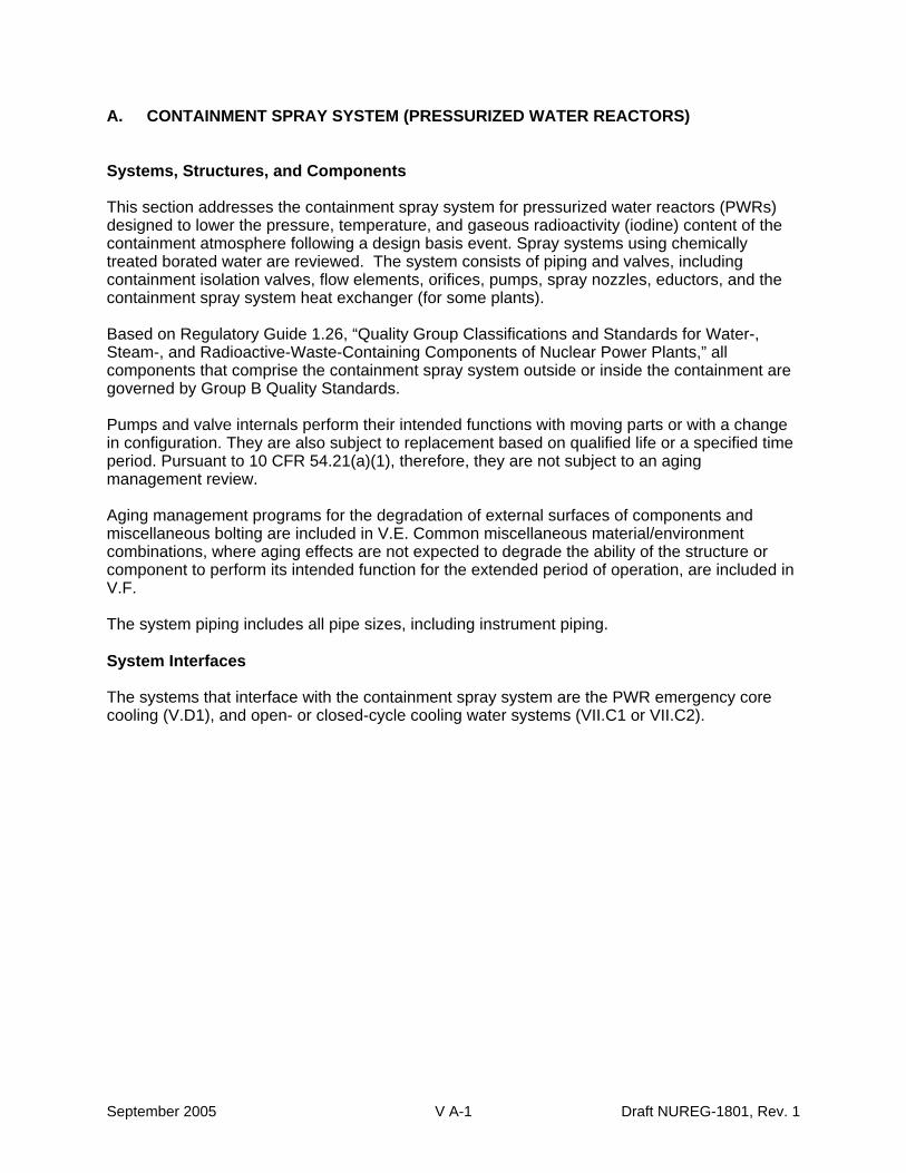
A. CONTAINMENT SPRAY SYSTEM (PRESSURIZED WATER REACTORS)
Systems, Structures, and Components
This section addresses the containment spray system for pressurized water reactors (PWRs) designed to lower the pressure, temperature, and gaseous radioactivity (iodine) content of the containment atmosphere following a design basis event. Spray systems using chemically treated borated water are reviewed. The system consists of piping and valves, including containment isolation valves, flow elements, orifices, pumps, spray nozzles, eductors, and the containment spray system heat exchanger (for some plants).
Based on Regulatory Guide 1.26, “Quality Group Classifications and Standards for Water-, Steam-, and Radioactive-Waste-Containing Components of Nuclear Power Plants,” all components that comprise the containment spray system outside or inside the containment are governed by Group B Quality Standards.
Pumps and valve internals perform their intended functions with moving parts or with a change in configuration. They are also subject to replacement based on qualified life or a specified time period. Pursuant to 10 CFR 54.21(a)(1), therefore, they are not subject to an aging management review.
Aging management programs for the degradation of external surfaces of components and miscellaneous bolting are included in V.E. Common miscellaneous material/environment combinations, where aging effects are not expected to degrade the ability of the structure or component to perform its intended function for the extended period of operation, are included in V.F.
The system piping includes all pipe sizes, including instrument piping.
System Interfaces
The systems that interface with the containment spray system are the PWR emergency core cooling (V.D1), and open- or closed-cycle cooling water systems (VII.C1 or VII.C2).
September 2005 V A-1 Draft NUREG-1801, Rev. 1
This Page Intentionally Left Blank
Draft NUREG-1801, Rev. 1 V A-2 September 2005
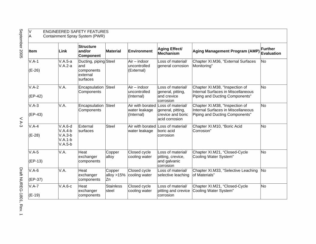
V ENGINEERED SAFETY FEATURES A Containment Spray System (PWR)
Item Link Structure and/or Component
Material Environment Aging Effect/ Mechanism Aging Management Program (AMP) Further
Evaluation
V.A-1
(E-26)
V.A.5-a V.A.2-a
Ducting, piping and components external surfaces
Steel Air – indoor uncontrolled (External)
Loss of material/ general corrosion
Chapter XI.M36, "External Surfaces Monitoring"
No
V.A-2
(EP-42)
V.A. Encapsulation Components
Steel Air – indoor uncontrolled (Internal)
Loss of material/ general, pitting, and crevice corrosion
Chapter XI.M38, "Inspection of Internal Surfaces in Miscellaneous Piping and Ducting Components"
No
V.A-3
(EP-43)
V.A. Encapsulation Components
Steel Air with borated water leakage (Internal)
Loss of material/ general, pitting, crevice and boric acid corrosion
Chapter XI.M38, "Inspection of Internal Surfaces in Miscellaneous Piping and Ducting Components"
No
V.A-4
(E-28)
V.A.6-d V.A.4-b V.A.3-b V.A.1-b V.A.5-b
External surfaces
Steel Air with borated water leakage
Loss of material/ boric acid corrosion
Chapter XI.M10, “Boric Acid Corrosion”
No
V.A-5
(EP-13)
V.A. Heat exchanger components
Copper alloy
Closed cycle cooling water
Loss of material/ pitting, crevice, and galvanic corrosion
Chapter XI.M21, “Closed-Cycle Cooling Water System”
No
V.A-6
(EP-37)
V.A. Heat exchanger components
Copper alloy >15% Zn
Closed cycle cooling water
Loss of material/ selective leaching
Chapter XI.M33, “Selective Leaching of Materials”
No
V.A-7
(E-19)
V.A.6-c Heat exchanger components
Stainless steel
Closed cycle cooling water
Loss of material/ pitting and crevice corrosion
Chapter XI.M21, “Closed-Cycle Cooling Water System”
No
Septem
ber 2005 V
A-3
Draft N
UR
EG
-1801, Rev. 1
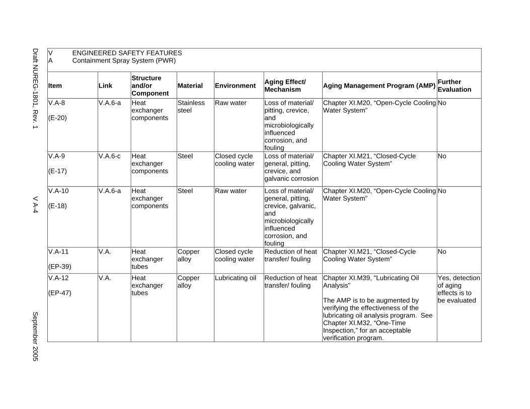
V ENGINEERED SAFETY FEATURES A Containment Spray System (PWR)
Item Link Structure and/or Component
Material Environment Aging Effect/ Mechanism Aging Management Program (AMP) Further
Evaluation
V.A-8
(E-20)
V.A.6-a Heat exchanger components
Stainless steel
Raw water Loss of material/ pitting, crevice, and microbiologically influenced corrosion, and fouling
Chapter XI.M20, “Open-Cycle Cooling Water System”
No
V.A-9
(E-17)
V.A.6-c Heat exchanger components
Steel Closed cycle cooling water
Loss of material/ general, pitting, crevice, and galvanic corrosion
Chapter XI.M21, “Closed-Cycle Cooling Water System”
No
V.A-10
(E-18)
V.A.6-a Heat exchanger components
Steel Raw water Loss of material/ general, pitting, crevice, galvanic, and microbiologically influenced corrosion, and fouling
Chapter XI.M20, “Open-Cycle Cooling Water System”
No
V.A-11
(EP-39)
V.A. Heat exchanger tubes
Copper alloy
Closed cycle cooling water
Reduction of heat transfer/ fouling
Chapter XI.M21, “Closed-Cycle Cooling Water System”
No
V.A-12
(EP-47)
V.A. Heat exchanger tubes
Copper alloy
Lubricating oil Reduction of heat transfer/ fouling
Chapter XI.M39, "Lubricating Oil Analysis"
The AMP is to be augmented by verifying the effectiveness of the lubricating oil analysis program. See Chapter XI.M32, “One-Time Inspection,” for an acceptable verification program.
Yes, detection of aging effects is to be evaluated
Draft N
UR
EG
-1801, Rev. 1
V A
-4 S
eptember 2005
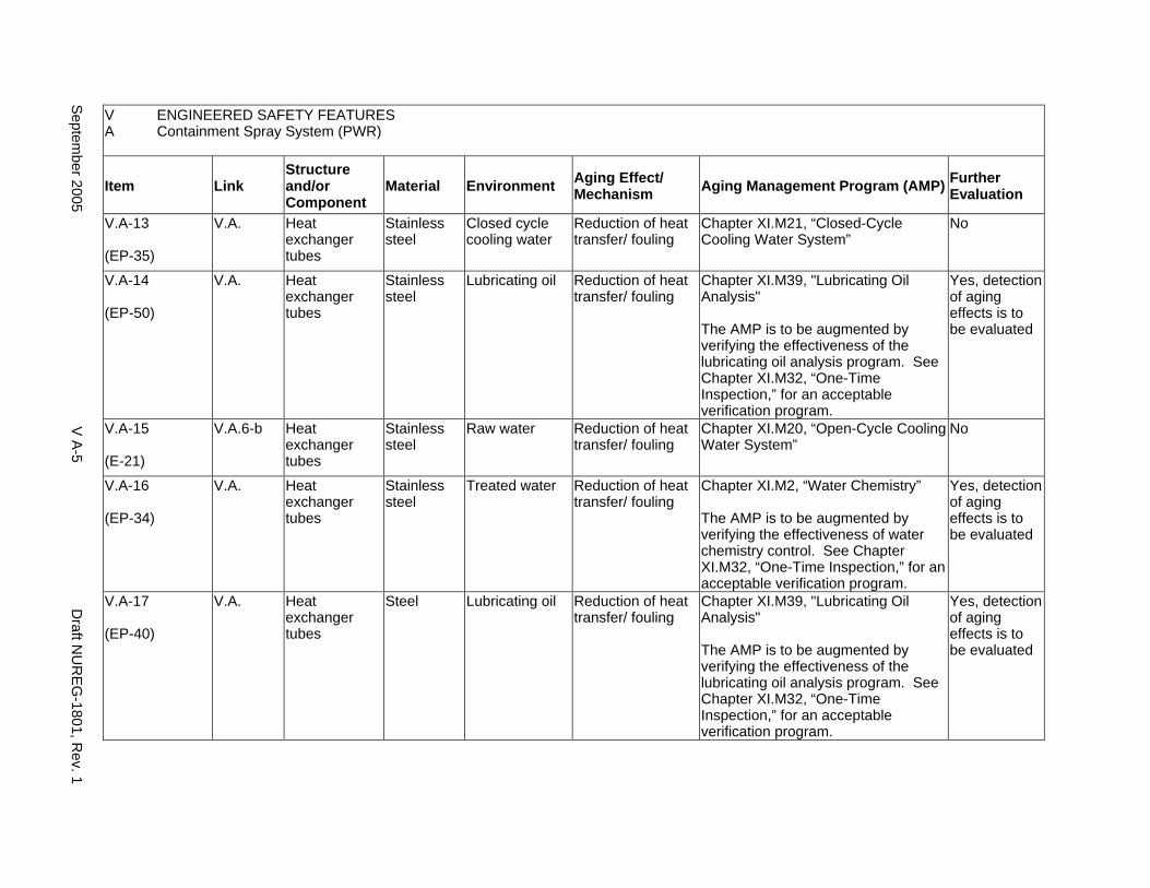
V ENGINEERED SAFETY FEATURES A Containment Spray System (PWR)
Item Link Structure and/or Component
Material Environment Aging Effect/ Mechanism Aging Management Program (AMP) Further
Evaluation
V.A-13
(EP-35)
V.A. Heat exchanger tubes
Stainless steel
Closed cycle cooling water
Reduction of heat transfer/ fouling
Chapter XI.M21, “Closed-Cycle Cooling Water System”
No
V.A-14
(EP-50)
V.A. Heat exchanger tubes
Stainless steel
Lubricating oil Reduction of heat transfer/ fouling
Chapter XI.M39, "Lubricating Oil Analysis"
The AMP is to be augmented by verifying the effectiveness of the lubricating oil analysis program. See Chapter XI.M32, “One-Time Inspection,” for an acceptable verification program.
Yes, detection of aging effects is to be evaluated
V.A-15
(E-21)
V.A.6-b Heat exchanger tubes
Stainless steel
Raw water Reduction of heat transfer/ fouling
Chapter XI.M20, “Open-Cycle Cooling Water System”
No
V.A-16
(EP-34)
V.A. Heat exchanger tubes
Stainless steel
Treated water Reduction of heat transfer/ fouling
Chapter XI.M2, “Water Chemistry”
The AMP is to be augmented by verifying the effectiveness of water chemistry control. See Chapter XI.M32, “One-Time Inspection,” for an acceptable verification program.
Yes, detection of aging effects is to be evaluated
V.A-17
(EP-40)
V.A. Heat exchanger tubes
Steel Lubricating oil Reduction of heat transfer/ fouling
Chapter XI.M39, "Lubricating Oil Analysis"
The AMP is to be augmented by verifying the effectiveness of the lubricating oil analysis program. See Chapter XI.M32, “One-Time Inspection,” for an acceptable verification program.
Yes, detection of aging effects is to be evaluated
Septem
ber 2005 V
A-5
Draft N
UR
EG
-1801, Rev. 1
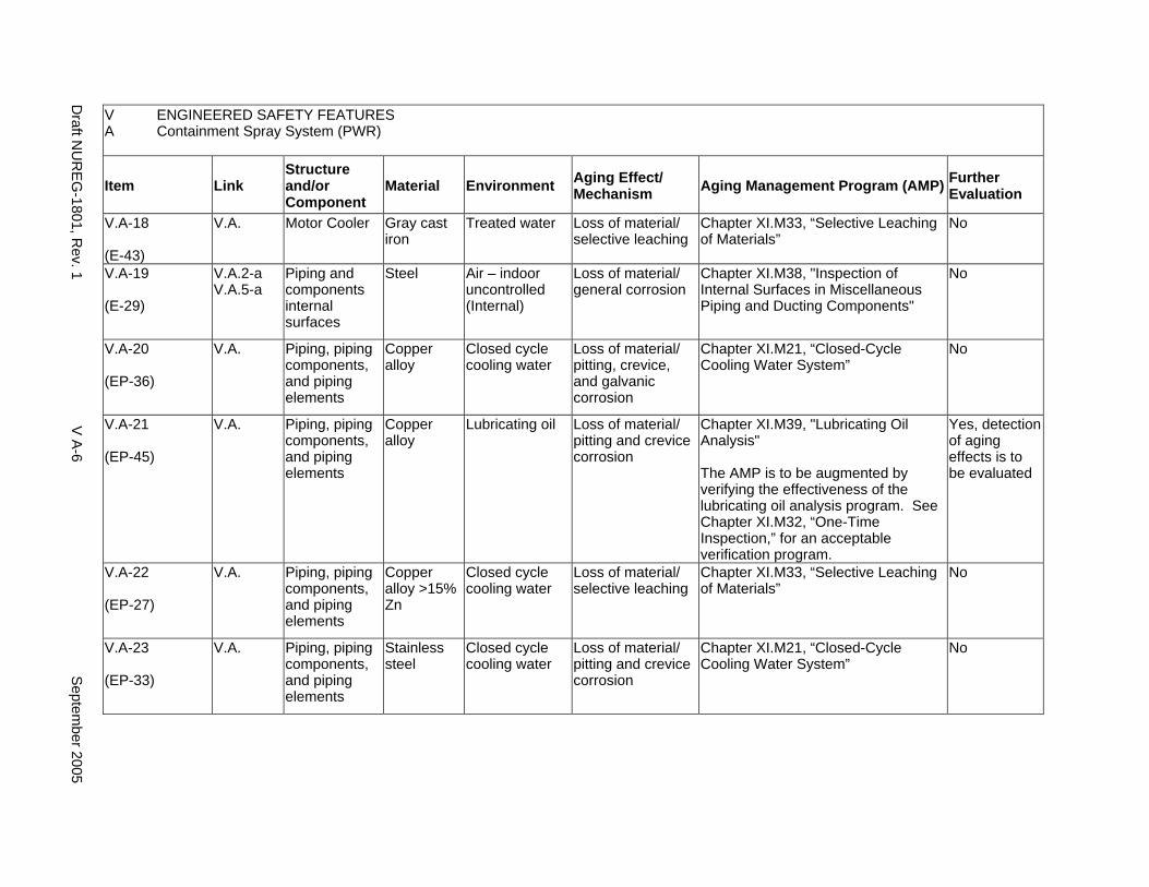
V ENGINEERED SAFETY FEATURES A Containment Spray System (PWR)
Item Link Structure and/or Component
Material Environment Aging Effect/ Mechanism Aging Management Program (AMP) Further
Evaluation
V.A-18
(E-43)
V.A. Motor Cooler Gray cast iron
Treated water Loss of material/ selective leaching
Chapter XI.M33, “Selective Leaching of Materials”
No
V.A-19
(E-29)
V.A.2-a V.A.5-a
Piping and components internal surfaces
Steel Air – indoor uncontrolled (Internal)
Loss of material/ general corrosion
Chapter XI.M38, "Inspection of Internal Surfaces in Miscellaneous Piping and Ducting Components"
No
V.A-20
(EP-36)
V.A. Piping, piping components, and piping elements
Copper alloy
Closed cycle cooling water
Loss of material/ pitting, crevice, and galvanic corrosion
Chapter XI.M21, “Closed-Cycle Cooling Water System”
No
V.A-21
(EP-45)
V.A. Piping, piping components, and piping elements
Copper alloy
Lubricating oil Loss of material/ pitting and crevice corrosion
Chapter XI.M39, "Lubricating Oil Analysis"
The AMP is to be augmented by verifying the effectiveness of the lubricating oil analysis program. See Chapter XI.M32, “One-Time Inspection,” for an acceptable verification program.
Yes, detection of aging effects is to be evaluated
V.A-22
(EP-27)
V.A. Piping, piping components, and piping elements
Copper alloy >15% Zn
Closed cycle cooling water
Loss of material/ selective leaching
Chapter XI.M33, “Selective Leaching of Materials”
No
V.A-23
(EP-33)
V.A. Piping, piping components, and piping elements
Stainless steel
Closed cycle cooling water
Loss of material/ pitting and crevice corrosion
Chapter XI.M21, “Closed-Cycle Cooling Water System”
No
Draft N
UR
EG
-1801, Rev. 1
V A
-6 S
eptember 2005
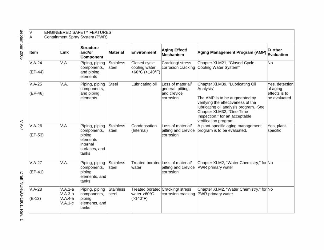
V ENGINEERED SAFETY FEATURES A Containment Spray System (PWR)
Item Link Structure and/or Component
Material Environment Aging Effect/ Mechanism Aging Management Program (AMP) Further
Evaluation
V.A-24
(EP-44)
V.A. Piping, piping components, and piping elements
Stainless steel
Closed cycle cooling water >60°C (>140°F)
Cracking/ stress corrosion cracking
Chapter XI.M21, “Closed-Cycle Cooling Water System”
No
V.A-25
(EP-46)
V.A. Piping, piping components, and piping elements
Steel Lubricating oil Loss of material/ general, pitting, and crevice corrosion
Chapter XI.M39, "Lubricating Oil Analysis"
The AMP is to be augmented by verifying the effectiveness of the lubricating oil analysis program. See Chapter XI.M32, “One-Time Inspection,” for an acceptable verification program.
Yes, detection of aging effects is to be evaluated
V.A-26
(EP-53)
V.A. Piping, piping components, piping elements internal surfaces, and tanks
Stainless steel
Condensation (Internal)
Loss of material/ pitting and crevice corrosion
A plant-specific aging management program is to be evaluated.
Yes, plant-specific
V.A-27
(EP-41)
V.A. Piping, piping components, piping elements, and tanks
Stainless steel
Treated borated water
Loss of material/ pitting and crevice corrosion
Chapter XI.M2, “Water Chemistry,” for PWR primary water
No
V.A-28
(E-12)
V.A.1-a V.A.3-a V.A.4-a V.A.1-c
Piping, piping components, piping elements, and tanks
Stainless steel
Treated borated water >60°C (>140°F)
Cracking/ stress corrosion cracking
Chapter XI.M2, “Water Chemistry,” for PWR primary water
No
Septem
ber 2005 V
A-7
Draft N
UR
EG
-1801, Rev. 1
This Page Intentionally Left Blank
Draft NUREG-1801, Rev. 1 V A-8 September 2005
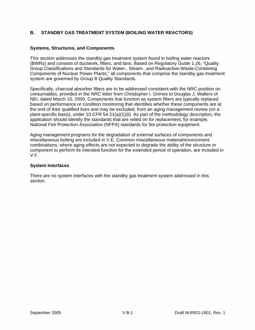
B. STANDBY GAS TREATMENT SYSTEM (BOILING WATER REACTORS)
Systems, Structures, and Components
This section addresses the standby gas treatment system found in boiling water reactors (BWRs) and consists of ductwork, filters, and fans. Based on Regulatory Guide 1.26, “Quality Group Classifications and Standards for Water-, Steam-, and Radioactive-Waste-Containing Components of Nuclear Power Plants,” all components that comprise the standby gas treatment system are governed by Group B Quality Standards.
Specifically, charcoal absorber filters are to be addressed consistent with the NRC position on consumables, provided in the NRC letter from Christopher I. Grimes to Douglas J. Walters of NEI, dated March 10, 2000. Components that function as system filters are typically replaced based on performance or condition monitoring that identifies whether these components are at the end of their qualified lives and may be excluded, from an aging management review (on a plant-specific basis), under 10 CFR 54.21(a)(1)(ii). As part of the methodology description, the application should identify the standards that are relied on for replacement, for example, National Fire Protection Association (NFPA) standards for fire protection equipment.
Aging management programs for the degradation of external surfaces of components and miscellaneous bolting are included in V.E. Common miscellaneous material/environment combinations, where aging effects are not expected to degrade the ability of the structure or component to perform its intended function for the extended period of operation, are included in V.F.
System Interfaces
There are no system interfaces with the standby gas treatment system addressed in this section.
September 2005 V B-1 Draft NUREG-1801, Rev. 1
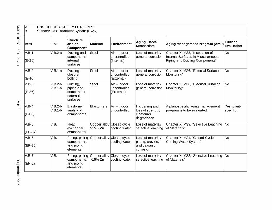
V ENGINEERED SAFETY FEATURES B Standby Gas Treatment System (BWR)
Item Link Structure and/or Component
Material Environment Aging Effect/ Mechanism Aging Management Program (AMP) Further
Evaluation
V.B-1
(E-25)
V.B.2-a Ducting and components internal surfaces
Steel Air – indoor uncontrolled (Internal)
Loss of material/ general corrosion
Chapter XI.M38, "Inspection of Internal Surfaces in Miscellaneous Piping and Ducting Components"
No
V.B-2
(E-40)
V.B.1-a Ducting closure bolting
Steel Air – indoor uncontrolled (External)
Loss of material/ general corrosion
Chapter XI.M36, "External Surfaces Monitoring"
No
V.B-3
(E-26)
V.B.2-a V.B.1-a
Ducting, piping and components external surfaces
Steel Air – indoor uncontrolled (External)
Loss of material/ general corrosion
Chapter XI.M36, "External Surfaces Monitoring"
No
V.B-4
(E-06)
V.B.2-b V.B.1-b
Elastomer seals and components
Elastomers Air – indoor uncontrolled
Hardening and loss of strength/ elastomer degradation
A plant-specific aging management program is to be evaluated.
Yes, plant-specific
V.B-5
(EP-37)
V.B. Heat exchanger components
Copper alloy >15% Zn
Closed cycle cooling water
Loss of material/ selective leaching
Chapter XI.M33, “Selective Leaching of Materials”
No
V.B-6
(EP-36)
V.B. Piping, piping components, and piping elements
Copper alloy Closed cycle cooling water
Loss of material/ pitting, crevice, and galvanic corrosion
Chapter XI.M21, “Closed-Cycle Cooling Water System”
No
V.B-7
(EP-27)
V.B. Piping, piping components, and piping elements
Copper alloy >15% Zn
Closed cycle cooling water
Loss of material/ selective leaching
Chapter XI.M33, “Selective Leaching of Materials”
No
Draft N
UR
EG
-1801, Rev. 1
V B
-2 S
eptember 2005
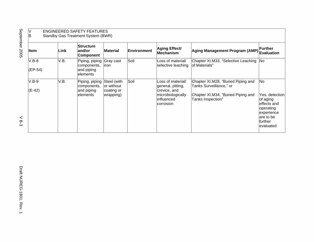
V ENGINEERED SAFETY FEATURES B Standby Gas Treatment System (BWR)
Item Link Structure and/or Component
Material Environment Aging Effect/ Mechanism Aging Management Program (AMP) Further
Evaluation
V.B-8
(EP-54)
V.B. Piping, piping components, and piping elements
Gray cast iron
Soil Loss of material/ selective leaching
Chapter XI.M33, “Selective Leaching of Materials"
No
V.B-9
(E-42)
V.B. Piping, piping components, and piping elements
Steel (with or without coating or wrapping)
Soil Loss of material/ general, pitting, crevice, and microbiologically influenced corrosion
Chapter XI.M28, “Buried Piping and Tanks Surveillance,” or
Chapter XI.M34, “Buried Piping and Tanks Inspection”
No
Yes, detection of aging effects and operating experience are to be further evaluated
Septem
ber 2005 V
B-3
Draft N
UR
EG
-1801, Rev. 1

This Page Intentionally Left Blank
Draft NUREG-1801, Rev. 1 V B-4 September 2005
C. CONTAINMENT ISOLATION COMPONENTS
Systems, Structures, and Components
This section addresses the containment isolation components found in all designs of boiling water reactors (BWR) and pressurized water reactors (PWR) in the United States. The system consists of isolation barriers in lines for BWR and PWR nonsafety systems such as the plant heating, waste gas, plant drain, liquid waste, and cooling water systems. Based on Regulatory Guide 1.26, “Quality Group Classifications and Standards for Water-, Steam-, and Radioactive-Waste-Containing Components of Nuclear Power Plants,” all components that comprise the containment isolation components are governed by Group A or B Quality Standards.
The aging management programs for hatchways, hatch doors, penetration sleeves, penetration bellows, seals, gaskets, and anchors are addressed in II.A and II.B. The containment isolation valves for in-scope systems are addressed in the appropriate sections in IV, VII, and VIII.
Aging management programs for the degradation of external surfaces of components and miscellaneous bolting are included in V.E. Common miscellaneous material/environment combinations, where aging effects are not expected to degrade the ability of the structure or component to perform its intended function for the extended period of operation, are included in V.F.
System Interfaces
There are no system interfaces with the containment isolation components addressed in this section.
September 2005 V C-1 Draft NUREG-1801, Rev. 1
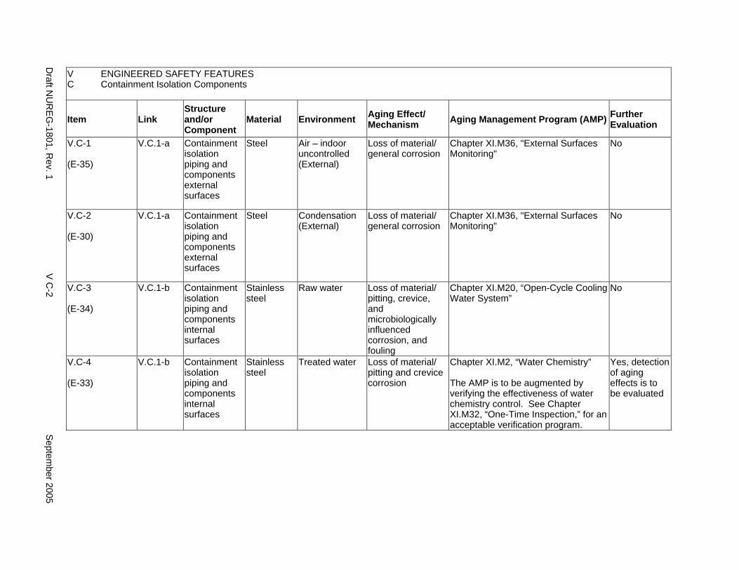
V C
ENGINEERED SAFETY FEATURES Containment Isolation Components
Item Link Structure and/or Component
Material Environment Aging Effect/ Mechanism Aging Management Program (AMP) Further
Evaluation
V.C-1
(E-35)
V.C.1-a Containment isolation piping and components external surfaces
Steel Air – indoor uncontrolled (External)
Loss of material/ general corrosion
Chapter XI.M36, "External Surfaces Monitoring"
No
V.C-2
(E-30)
V.C.1-a Containment isolation piping and components external surfaces
Steel Condensation (External)
Loss of material/ general corrosion
Chapter XI.M36, "External Surfaces Monitoring"
No
V.C-3
(E-34)
V.C.1-b Containment isolation piping and components internal surfaces
Stainless steel
Raw water Loss of material/ pitting, crevice, and microbiologically influenced corrosion, and fouling
Chapter XI.M20, “Open-Cycle Cooling Water System”
No
V.C-4
(E-33)
V.C.1-b Containment isolation piping and components internal surfaces
Stainless steel
Treated water Loss of material/ pitting and crevice corrosion
Chapter XI.M2, “Water Chemistry”
The AMP is to be augmented by verifying the effectiveness of water chemistry control. See Chapter XI.M32, “One-Time Inspection,” for an acceptable verification program.
Yes, detection of aging effects is to be evaluated
Draft N
UR
EG
-1801, Rev. 1
V C
-2 S
eptember 2005
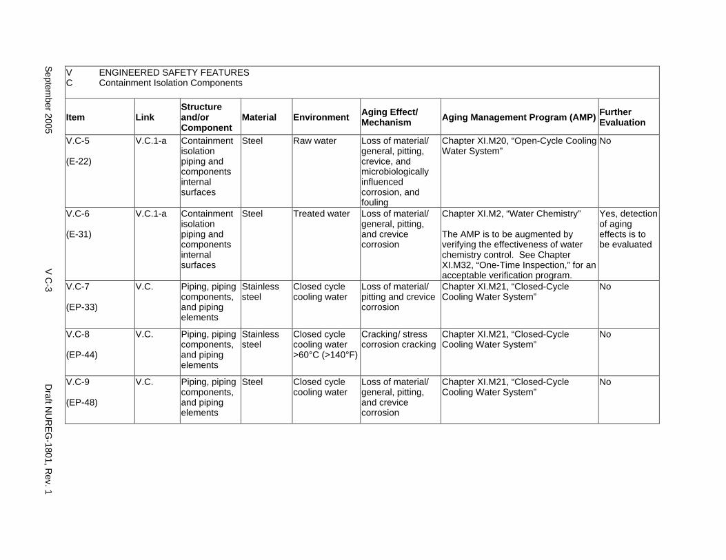
V ENGINEERED SAFETY FEATURES C Containment Isolation Components
Item Link Structure and/or Component
Material Environment Aging Effect/ Mechanism Aging Management Program (AMP) Further
Evaluation
V.C-5
(E-22)
V.C.1-a Containment isolation piping and components internal surfaces
Steel Raw water Loss of material/ general, pitting, crevice, and microbiologically influenced corrosion, and fouling
Chapter XI.M20, “Open-Cycle Cooling Water System”
No
V.C-6
(E-31)
V.C.1-a Containment isolation piping and components internal surfaces
Steel Treated water Loss of material/ general, pitting, and crevice corrosion
Chapter XI.M2, “Water Chemistry”
The AMP is to be augmented by verifying the effectiveness of water chemistry control. See Chapter XI.M32, “One-Time Inspection,” for an acceptable verification program.
Yes, detection of aging effects is to be evaluated
V.C-7
(EP-33)
V.C. Piping, piping components, and piping elements
Stainless steel
Closed cycle cooling water
Loss of material/ pitting and crevice corrosion
Chapter XI.M21, “Closed-Cycle Cooling Water System”
No
V.C-8
(EP-44)
V.C. Piping, piping components, and piping elements
Stainless steel
Closed cycle cooling water >60°C (>140°F)
Cracking/ stress corrosion cracking
Chapter XI.M21, “Closed-Cycle Cooling Water System”
No
V.C-9
(EP-48)
V.C. Piping, piping components, and piping elements
Steel Closed cycle cooling water
Loss of material/ general, pitting, and crevice corrosion
Chapter XI.M21, “Closed-Cycle Cooling Water System”
No
Septem
ber 2005 V
C-3
Draft N
UR
EG
-1801, Rev. 1

This Page Intentionally Left Blank
Draft NUREG-1801, Rev. 1 V C-4 September 2005
D1. EMERGENCY CORE COOLING SYSTEM (PRESSURIZED WATER REACTORS)
Systems, Structures, and Components
This section addresses the emergency core cooling systems for pressurized water reactors (PWRs) designed to cool the reactor core and provide safe shutdown following a design basis accident. They consist of the core flood system (CFS), residual heat removal (RHR) (or shutdown cooling (SDC)), high-pressure safety injection (HPSI), low-pressure safety injection (LPSI), and spent fuel pool (SFP) cooling systems, the lines to the chemical and volume control system (CVCS), the emergency sump, the HPSI and LPSI pumps, the pump seal coolers, the RHR heat exchanger, and the refueling water tank (RWT).
Based on Regulatory Guide 1.26, “Quality Group Classifications and Standards for Water-, Steam-, and Radioactive-Waste-Containing Components of Nuclear Power Plants,” all components that comprise the emergency core cooling system are governed by Group B Quality Standards. Portions of the RHR, HPSI, and LPSI systems and the CVCS extending from the reactor coolant system up to and including the second containment isolation valve are governed by Group A Quality Standards and covered in IV.C2.
Pumps and valve internals perform their intended functions with moving parts or with a change in configuration. They are also subject to replacement based on qualified life or a specified time period. Pursuant to 10 CFR 54.21(a)(1), therefore, they are not subject to an aging management review.
Aging management programs for the degradation of external surfaces of components and miscellaneous bolting are included in V.E. Common miscellaneous material/environment combinations, where aging effects are not expected to degrade the ability of the structure or component to perform its intended function for the extended period of operation, are included in VI.F.
The system piping includes all pipe sizes, including instrument piping.
System Interfaces
The systems that interface with the emergency core cooling system include the reactor coolant system and connected lines (IV.C2), the containment spray system (V.A), the spent fuel pool cooling and cleanup system (VII.A3), the closed-cycle cooling water system (VII.C2), the ultimate heat sink (VII.C3), the chemical and volume control system (VII.E1), and the open-cycle cooling water system (service water system) (VII.C1).
September 2005 V D1-1 Draft NUREG-1801, Rev. 1
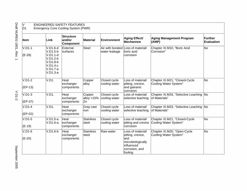
V ENGINEERED SAFETY FEATURES D1 Emergency Core Cooling System (PWR)
Item Link Structure and/or Component
Material Environment Aging Effect/ Mechanism
Aging Management Program (AMP)
Further Evaluation
V.D1-1
(E-28)
V.D1.6-d V.D1.5-b V.D1.1-d V.D1.2-b V.D1.8-b V.D1.4-c V.D1.7-a V.D1.3-a
External surfaces
Steel Air with borated water leakage
Loss of material/ boric acid corrosion
Chapter XI.M10, “Boric Acid Corrosion”
No
V.D1-2
(EP-13)
V.D1. Heat exchanger components
Copper alloy
Closed cycle cooling water
Loss of material/ pitting, crevice, and galvanic corrosion
Chapter XI.M21, “Closed-Cycle Cooling Water System”
No
V.D1-3
(EP-37)
V.D1. Heat exchanger components
Copper alloy >15% Zn
Closed cycle cooling water
Loss of material/ selective leaching
Chapter XI.M33, “Selective Leaching of Materials”
No
V.D1-4
(EP-52)
V.D1. Heat exchanger components
Gray cast iron
Closed cycle cooling water
Loss of material/ selective leaching
Chapter XI.M33, “Selective Leaching of Materials”
No
V.D1-5
(E-19)
V.D1.5-a V.D1.6-a
Heat exchanger components
Stainless steel
Closed cycle cooling water
Loss of material/ pitting and crevice corrosion
Chapter XI.M21, “Closed-Cycle Cooling Water System”
No
V.D1-6
(E-20)
V.D1.6-b Heat exchanger components
Stainless steel
Raw water Loss of material/ pitting, crevice, and microbiologically influenced corrosion, and fouling
Chapter XI.M20, “Open-Cycle Cooling Water System”
No
Draft N
UR
EG
-1801, Rev. 1
V D
1-2 S
eptember 2005

V ENGINEERED SAFETY FEATURES D1 Emergency Core Cooling System (PWR)
Item Link Structure and/or Component
Material Environment Aging Effect/ Mechanism
Aging Management Program (AMP)
Further Evaluation
V.D1-7
(E-17)
V.D1.6-a V.D1.5-a
Heat exchanger components
Steel Closed cycle cooling water
Loss of material/ general, pitting, crevice, and galvanic corrosion
Chapter XI.M21, “Closed-Cycle Cooling Water System”
No
V.D1-8
(E-18)
V.D1.6-b Heat exchanger components
Steel Raw water Loss of material/ general, pitting, crevice, galvanic, and microbiologically influenced corrosion, and fouling
Chapter XI.M20, “Open-Cycle Cooling Water System”
No
V.D1-9
(EP-47)
V.D1. Heat exchanger tubes
Copper alloy
Lubricating oil Reduction of heat transfer/ fouling
Chapter XI.M39, "Lubricating Oil Analysis"
The AMP is to be augmented by verifying the effectiveness of the lubricating oil analysis program. See Chapter XI.M32, “One-Time Inspection,” for an acceptable verification program.
Yes, detection of aging effects is to be evaluated
V.D1-10
(EP-35)
V.D1. Heat exchanger tubes
Stainless steel
Closed cycle cooling water
Reduction of heat transfer/ fouling
Chapter XI.M21, “Closed-Cycle Cooling Water System”
No
V.D1-11
(EP-50)
V.D1. Heat exchanger tubes
Stainless steel
Lubricating oil Reduction of heat transfer/ fouling
Chapter XI.M39, "Lubricating Oil Analysis"
The AMP is to be augmented by verifying the effectiveness of the lubricating oil analysis program. See Chapter XI.M32, “One-Time Inspection,” for an acceptable verification program.
Yes, detection of aging effects is to be evaluated
Septem
ber 2005 V
D1-3
Draft N
UR
EG
-1801, Rev. 1

V ENGINEERED SAFETY FEATURES D1 Emergency Core Cooling System (PWR)
Item Link Structure and/or Component
Material Environment Aging Effect/ Mechanism
Aging Management Program (AMP)
Further Evaluation
V.D1-12
(E-21)
V.D1.6-c Heat exchanger tubes
Stainless steel
Raw water Reduction of heat transfer/ fouling
Chapter XI.M20, “Open-Cycle Cooling Water System”
No
V.D1-13
(EP-40)
V.D1. Heat exchanger tubes
Steel Lubricating oil Reduction of heat transfer/ fouling
Chapter XI.M39, "Lubricating Oil Analysis"
The AMP is to be augmented by verifying the effectiveness of the lubricating oil analysis program. See Chapter XI.M32, “One-Time Inspection,” for an acceptable verification program.
Yes, detection of aging effects is to be evaluated
V.D1-14
(E-43)
V.D1. Motor Cooler Gray cast iron
Treated water Loss of material/ selective leaching
Chapter XI.M33, “Selective Leaching of Materials”
No
V.D1-15
(E-24)
V.D1.2-c Orifice (miniflow recirculation)
Stainless steel
Treated borated water
Loss of material/ erosion
A plant-specific aging management program is to be evaluated for erosion of the orifice due to extended use of the centrifugal HPSI pump for normal charging. See Licensee Event Report 50-275/94-023 for evidence of erosion.
Yes, plant-specific
V.D1-16
(E-01)
V.D1.8-c Partially encased tanks with breached moisture barrier
Stainless steel
Raw water Loss of material/ pitting and crevice corrosion
A plant-specific aging management program is to be evaluated for pitting and crevice corrosion of tank bottom because moisture and water can egress under the tank due to cracking of the perimeter seal from weathering.
Yes, plant-specific
V.D1-17
(E-47)
V.D1.1-b Piping, piping components, and piping elements
Cast austenitic stainless steel
Treated borated water >250°C (>482°F)
Loss of fracture toughness/ thermal aging embrittlement
Chapter XI.M12, “Thermal Aging Embrittlement of Cast Austenitic Stainless Steel (CASS)”
No
Draft N
UR
EG
-1801, Rev. 1
V D
1-4 S
eptember 2005
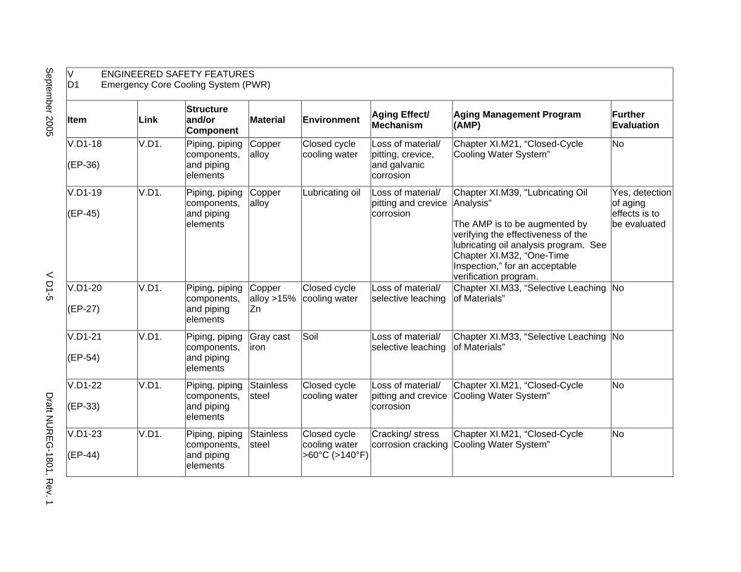
V ENGINEERED SAFETY FEATURES D1 Emergency Core Cooling System (PWR)
Item Link Structure and/or Component
Material Environment Aging Effect/ Mechanism
Aging Management Program (AMP)
Further Evaluation
V.D1-18
(EP-36)
V.D1. Piping, piping components, and piping elements
Copper alloy
Closed cycle cooling water
Loss of material/ pitting, crevice, and galvanic corrosion
Chapter XI.M21, “Closed-Cycle Cooling Water System”
No
V.D1-19
(EP-45)
V.D1. Piping, piping components, and piping elements
Copper alloy
Lubricating oil Loss of material/ pitting and crevice corrosion
Chapter XI.M39, "Lubricating Oil Analysis"
The AMP is to be augmented by verifying the effectiveness of the lubricating oil analysis program. See Chapter XI.M32, “One-Time Inspection,” for an acceptable verification program.
Yes, detection of aging effects is to be evaluated
V.D1-20
(EP-27)
V.D1. Piping, piping components, and piping elements
Copper alloy >15% Zn
Closed cycle cooling water
Loss of material/ selective leaching
Chapter XI.M33, “Selective Leaching of Materials”
No
V.D1-21
(EP-54)
V.D1. Piping, piping components, and piping elements
Gray cast iron
Soil Loss of material/ selective leaching
Chapter XI.M33, “Selective Leaching of Materials"
No
V.D1-22
(EP-33)
V.D1. Piping, piping components, and piping elements
Stainless steel
Closed cycle cooling water
Loss of material/ pitting and crevice corrosion
Chapter XI.M21, “Closed-Cycle Cooling Water System”
No
V.D1-23
(EP-44)
V.D1. Piping, piping components, and piping elements
Stainless steel
Closed cycle cooling water >60°C (>140°F)
Cracking/ stress corrosion cracking
Chapter XI.M21, “Closed-Cycle Cooling Water System”
No
Septem
ber 2005 V
D1-5
Draft N
UR
EG
-1801, Rev. 1
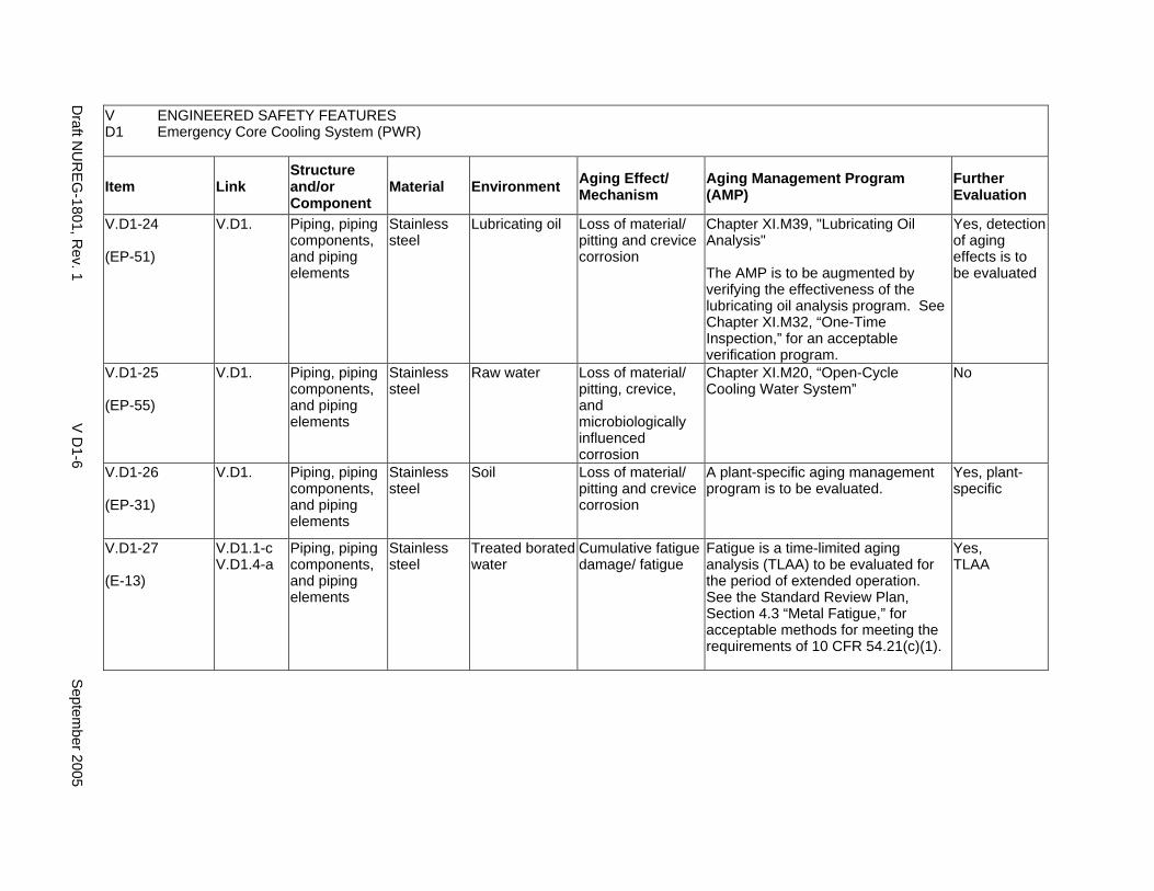
V ENGINEERED SAFETY FEATURES D1 Emergency Core Cooling System (PWR)
Item Link Structure and/or Component
Material Environment Aging Effect/ Mechanism
Aging Management Program (AMP)
Further Evaluation
V.D1-24
(EP-51)
V.D1. Piping, piping components, and piping elements
Stainless steel
Lubricating oil Loss of material/ pitting and crevice corrosion
Chapter XI.M39, "Lubricating Oil Analysis"
The AMP is to be augmented by verifying the effectiveness of the lubricating oil analysis program. See Chapter XI.M32, “One-Time Inspection,” for an acceptable verification program.
Yes, detection of aging effects is to be evaluated
V.D1-25
(EP-55)
V.D1. Piping, piping components, and piping elements
Stainless steel
Raw water Loss of material/ pitting, crevice, and microbiologically influenced corrosion
Chapter XI.M20, “Open-Cycle Cooling Water System”
No
V.D1-26
(EP-31)
V.D1. Piping, piping components, and piping elements
Stainless steel
Soil Loss of material/ pitting and crevice corrosion
A plant-specific aging management program is to be evaluated.
Yes, plant-specific
V.D1-27
(E-13)
V.D1.1-c V.D1.4-a
Piping, piping components, and piping elements
Stainless steel
Treated borated water
Cumulative fatigue damage/ fatigue
Fatigue is a time-limited aging analysis (TLAA) to be evaluated for the period of extended operation. See the Standard Review Plan, Section 4.3 “Metal Fatigue,” for acceptable methods for meeting the requirements of 10 CFR 54.21(c)(1).
Yes, TLAA
Draft N
UR
EG
-1801, Rev. 1
V D
1-6 S
eptember 2005
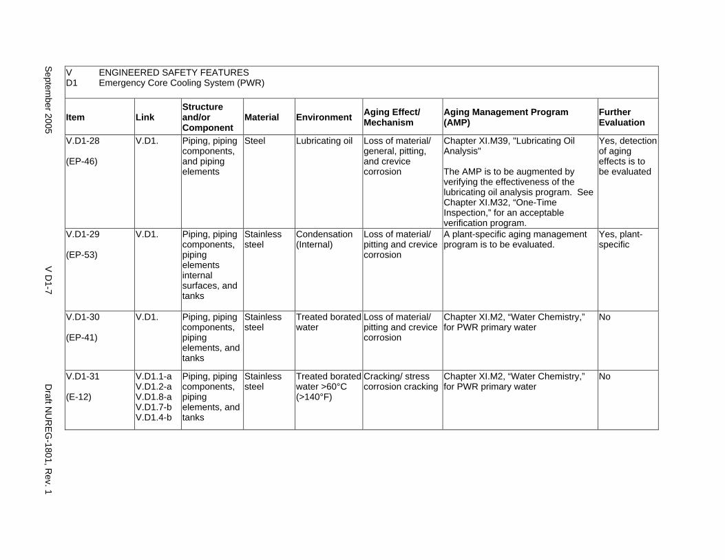
V ENGINEERED SAFETY FEATURES D1 Emergency Core Cooling System (PWR)
Item Link Structure and/or Component
Material Environment Aging Effect/ Mechanism
Aging Management Program (AMP)
Further Evaluation
V.D1-28
(EP-46)
V.D1. Piping, piping components, and piping elements
Steel Lubricating oil Loss of material/ general, pitting, and crevice corrosion
Chapter XI.M39, "Lubricating Oil Analysis"
The AMP is to be augmented by verifying the effectiveness of the lubricating oil analysis program. See Chapter XI.M32, “One-Time Inspection,” for an acceptable verification program.
Yes, detection of aging effects is to be evaluated
V.D1-29
(EP-53)
V.D1. Piping, piping components, piping elements internal surfaces, and tanks
Stainless steel
Condensation (Internal)
Loss of material/ pitting and crevice corrosion
A plant-specific aging management program is to be evaluated.
Yes, plant-specific
V.D1-30
(EP-41)
V.D1. Piping, piping components, piping elements, and tanks
Stainless steel
Treated borated water
Loss of material/ pitting and crevice corrosion
Chapter XI.M2, “Water Chemistry,” for PWR primary water
No
V.D1-31
(E-12)
V.D1.1-a V.D1.2-a V.D1.8-a V.D1.7-b V.D1.4-b
Piping, piping components, piping elements, and tanks
Stainless steel
Treated borated water >60°C (>140°F)
Cracking/ stress corrosion cracking
Chapter XI.M2, “Water Chemistry,” for PWR primary water
No
Septem
ber 2005 V
D1-7
Draft N
UR
EG
-1801, Rev. 1
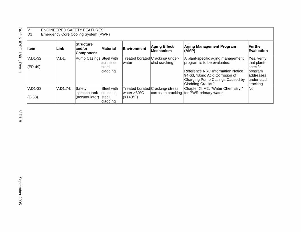
V ENGINEERED SAFETY FEATURES D1 Emergency Core Cooling System (PWR)
Item Link Structure and/or Component
Material Environment Aging Effect/ Mechanism
Aging Management Program (AMP)
Further Evaluation
V.D1-32
(EP-49)
V.D1. Pump Casings Steel with stainless steel cladding
Treated borated water
Cracking/ under-clad cracking
A plant-specific aging management program is to be evaluated.
Reference NRC Information Notice 94-63, “Boric Acid Corrosion of Charging Pump Casings Caused by Cladding Cracks."
Yes, verify that plant-specific program addresses under-clad cracking
V.D1-33
(E-38)
V.D1.7-b Safety injection tank (accumulator)
Steel with stainless steel cladding
Treated borated water >60°C (>140°F)
Cracking/ stress corrosion cracking
Chapter XI.M2, “Water Chemistry,” for PWR primary water
No
Draft N
UR
EG
-1801, Rev. 1
V D
1-8 S
eptember 2005
D2. EMERGENCY CORE COOLING SYSTEM (BOILING WATER REACTORS)
Systems, Structures, and Components
This section addresses the emergency core cooling systems for boiling water reactors (BWRs) designed to cool the reactor core and provide safe shutdown following a design basis accident. They consist of the high-pressure coolant injection (HPCI), reactor core isolation cooling (RCIC), high-pressure core spray (HPCS), automatic depressurization (ADS), low-pressure core spray (LPCS), low-pressure coolant injection (LPCI) and residual heat removal (RHR) systems, including various pumps and valves, the RHR heat exchangers, and the drywell and suppression chamber spray system (DSCSS). The auxiliary area ventilation system includes RCIC, HPCI, RHR, and core spray pump room cooling.
Based on Regulatory Guide 1.26, “Quality Group Classifications and Standards for Water-, Steam-, and Radioactive-Waste-Containing Components of Nuclear Power Plants,” all components that comprise the emergency core cooling system outside the containment are governed by Group B Quality Standards and the portion of the DSCSS inside the containment up to the isolation valve is governed by Group A Quality Standards. Portions of the HPCI, RCIC, HPCS, LPCS, and LPCI (or RHR) systems extending from the reactor vessel up to and including the second containment isolation valve are governed by Group A Quality Standards and covered in IV.C1.
Pumps and valve internals perform their intended functions with moving parts or with a change in configuration. They are also subject to replacement based on qualified life or a specified time period. Pursuant to 10 CFR 54.21(a)(1), therefore, they are not subject to an aging management review.
The system piping includes all pipe sizes, including instrument piping.
Aging management programs for the degradation of external surfaces of components and miscellaneous bolting are included in V.E. Common miscellaneous material/environment combinations, where aging effects are not expected to degrade the ability of the structure or component to perform its intended function for the extended period of operation, are included in VI.F.
System Interfaces
The systems that interface with the emergency core cooling system include the reactor vessel (IV.A1), the reactor coolant pressure boundary (IV.C1), the feedwater system (VIII.D2), the condensate system (VIII.E), the closed-cycle cooling water system (VII.C2), the open-cycle cooling water system (VII.C1), and the ultimate heat sink (VII.C3).
September 2005 V D2-1 Draft NUREG-1801, Rev. 1
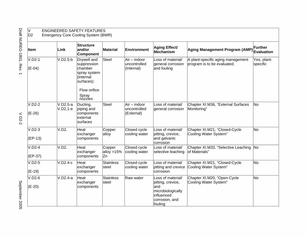
V ENGINEERED SAFETY FEATURES D2 Emergency Core Cooling System (BWR)
Item Link Structure and/or Component
Material Environment Aging Effect/ Mechanism Aging Management Program (AMP) Further
Evaluation
V.D2-1
(E-04)
V.D2.5-b Drywell and suppression chamber spray system (internal surfaces):
Flow orifice Spray nozzles
Steel Air – indoor uncontrolled (Internal)
Loss of material/ general corrosion and fouling
A plant-specific aging management program is to be evaluated.
Yes, plant-specific
V.D2-2
(E-26)
V.D2.5-a V.D2.1-e
Ducting, piping and components external surfaces
Steel Air – indoor uncontrolled (External)
Loss of material/ general corrosion
Chapter XI.M36, "External Surfaces Monitoring"
No
V.D2-3
(EP-13)
V.D2. Heat exchanger components
Copper alloy
Closed cycle cooling water
Loss of material/ pitting, crevice, and galvanic corrosion
Chapter XI.M21, “Closed-Cycle Cooling Water System”
No
V.D2-4
(EP-37)
V.D2. Heat exchanger components
Copper alloy >15% Zn
Closed cycle cooling water
Loss of material/ selective leaching
Chapter XI.M33, “Selective Leaching of Materials”
No
V.D2-5
(E-19)
V.D2.4-c Heat exchanger components
Stainless steel
Closed cycle cooling water
Loss of material/ pitting and crevice corrosion
Chapter XI.M21, “Closed-Cycle Cooling Water System”
No
V.D2-6
(E-20)
V.D2.4-a Heat exchanger components
Stainless steel
Raw water Loss of material/ pitting, crevice, and microbiologically influenced corrosion, and fouling
Chapter XI.M20, “Open-Cycle Cooling Water System”
No
Draft N
UR
EG
-1801, Rev. 1
V D
2-2 S
eptember 2005
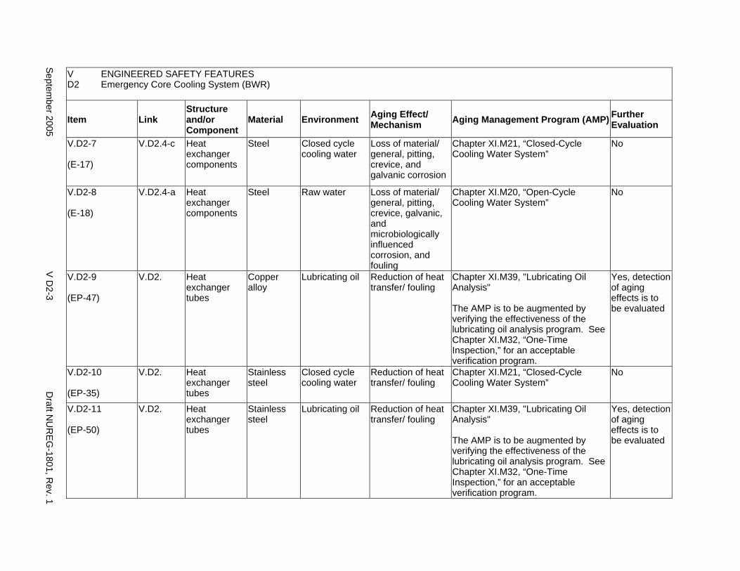
V ENGINEERED SAFETY FEATURES D2 Emergency Core Cooling System (BWR)
Item Link Structure and/or Component
Material Environment Aging Effect/ Mechanism Aging Management Program (AMP) Further
Evaluation
V.D2-7
(E-17)
V.D2.4-c Heat exchanger components
Steel Closed cycle cooling water
Loss of material/ general, pitting, crevice, and galvanic corrosion
Chapter XI.M21, “Closed-Cycle Cooling Water System”
No
V.D2-8
(E-18)
V.D2.4-a Heat exchanger components
Steel Raw water Loss of material/ general, pitting, crevice, galvanic, and microbiologically influenced corrosion, and fouling
Chapter XI.M20, “Open-Cycle Cooling Water System”
No
V.D2-9
(EP-47)
V.D2. Heat exchanger tubes
Copper alloy
Lubricating oil Reduction of heat transfer/ fouling
Chapter XI.M39, "Lubricating Oil Analysis"
The AMP is to be augmented by verifying the effectiveness of the lubricating oil analysis program. See Chapter XI.M32, “One-Time Inspection,” for an acceptable verification program.
Yes, detection of aging effects is to be evaluated
V.D2-10
(EP-35)
V.D2. Heat exchanger tubes
Stainless steel
Closed cycle cooling water
Reduction of heat transfer/ fouling
Chapter XI.M21, “Closed-Cycle Cooling Water System”
No
V.D2-11
(EP-50)
V.D2. Heat exchanger tubes
Stainless steel
Lubricating oil Reduction of heat transfer/ fouling
Chapter XI.M39, "Lubricating Oil Analysis"
The AMP is to be augmented by verifying the effectiveness of the lubricating oil analysis program. See Chapter XI.M32, “One-Time Inspection,” for an acceptable verification program.
Yes, detection of aging effects is to be evaluated
Septem
ber 2005 V
D2-3
Draft N
UR
EG
-1801, Rev. 1
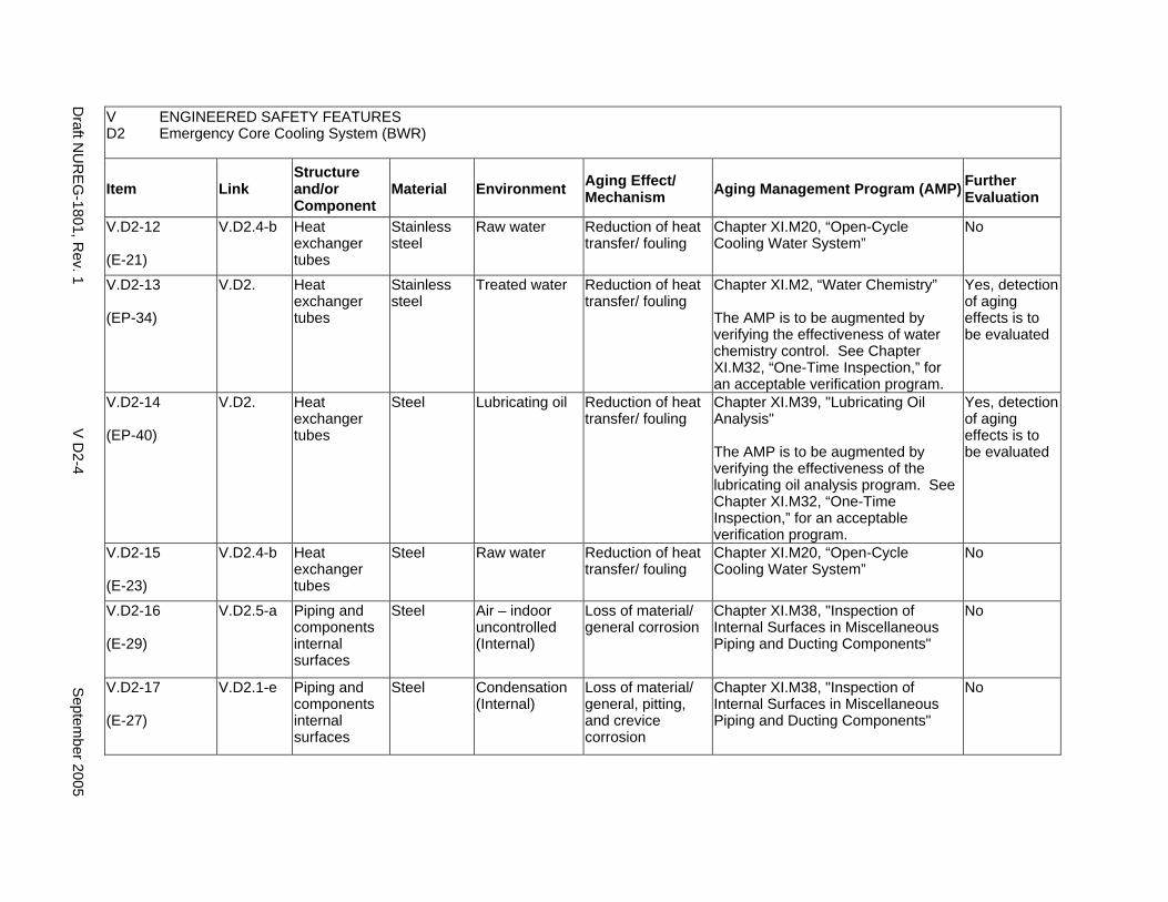
V ENGINEERED SAFETY FEATURES D2 Emergency Core Cooling System (BWR)
Item Link Structure and/or Component
Material Environment Aging Effect/ Mechanism Aging Management Program (AMP) Further
Evaluation
V.D2-12
(E-21)
V.D2.4-b Heat exchanger tubes
Stainless steel
Raw water Reduction of heat transfer/ fouling
Chapter XI.M20, “Open-Cycle Cooling Water System”
No
V.D2-13
(EP-34)
V.D2. Heat exchanger tubes
Stainless steel
Treated water Reduction of heat transfer/ fouling
Chapter XI.M2, “Water Chemistry”
The AMP is to be augmented by verifying the effectiveness of water chemistry control. See Chapter XI.M32, “One-Time Inspection,” for an acceptable verification program.
Yes, detection of aging effects is to be evaluated
V.D2-14
(EP-40)
V.D2. Heat exchanger tubes
Steel Lubricating oil Reduction of heat transfer/ fouling
Chapter XI.M39, "Lubricating Oil Analysis"
The AMP is to be augmented by verifying the effectiveness of the lubricating oil analysis program. See Chapter XI.M32, “One-Time Inspection,” for an acceptable verification program.
Yes, detection of aging effects is to be evaluated
V.D2-15
(E-23)
V.D2.4-b Heat exchanger tubes
Steel Raw water Reduction of heat transfer/ fouling
Chapter XI.M20, “Open-Cycle Cooling Water System”
No
V.D2-16
(E-29)
V.D2.5-a Piping and components internal surfaces
Steel Air – indoor uncontrolled (Internal)
Loss of material/ general corrosion
Chapter XI.M38, "Inspection of Internal Surfaces in Miscellaneous Piping and Ducting Components"
No
V.D2-17
(E-27)
V.D2.1-e Piping and components internal surfaces
Steel Condensation (Internal)
Loss of material/ general, pitting, and crevice corrosion
Chapter XI.M38, "Inspection of Internal Surfaces in Miscellaneous Piping and Ducting Components"
No
Draft N
UR
EG
-1801, Rev. 1
V D
2-4 S
eptember 2005
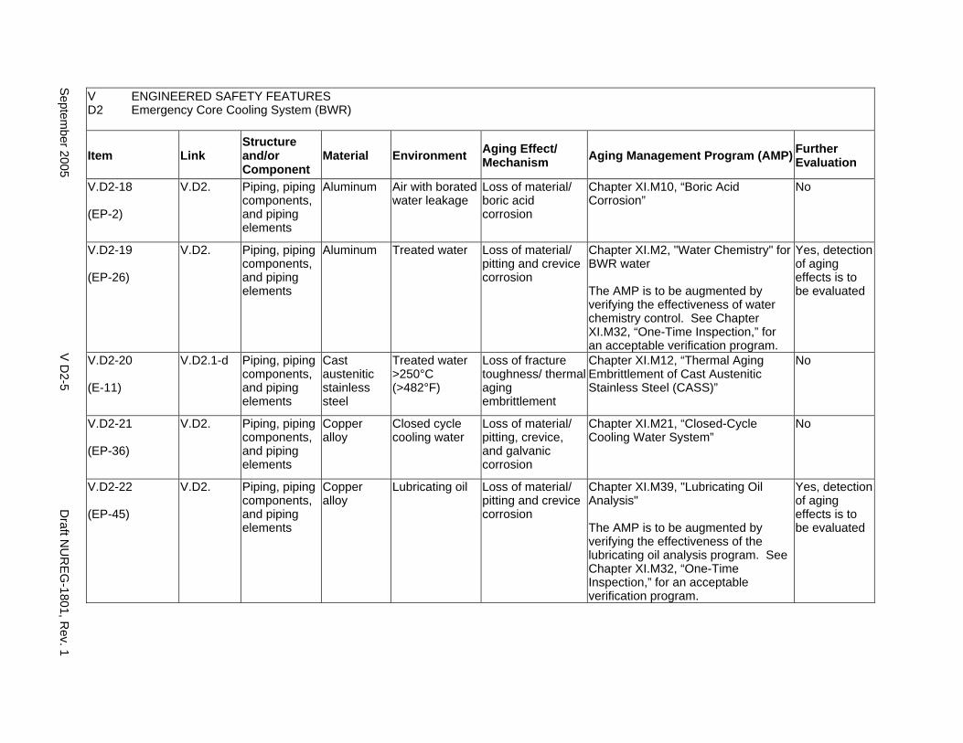
V ENGINEERED SAFETY FEATURES D2 Emergency Core Cooling System (BWR)
Item Link Structure and/or Component
Material Environment Aging Effect/ Mechanism Aging Management Program (AMP) Further
Evaluation
V.D2-18
(EP-2)
V.D2. Piping, piping components, and piping elements
Aluminum Air with borated water leakage
Loss of material/ boric acid corrosion
Chapter XI.M10, “Boric Acid Corrosion”
No
V.D2-19
(EP-26)
V.D2. Piping, piping components, and piping elements
Aluminum Treated water Loss of material/ pitting and crevice corrosion
Chapter XI.M2, "Water Chemistry" for BWR water
The AMP is to be augmented by verifying the effectiveness of water chemistry control. See Chapter XI.M32, “One-Time Inspection,” for an acceptable verification program.
Yes, detection of aging effects is to be evaluated
V.D2-20
(E-11)
V.D2.1-d Piping, piping components, and piping elements
Cast austenitic stainless steel
Treated water >250°C (>482°F)
Loss of fracture toughness/ thermal aging embrittlement
Chapter XI.M12, “Thermal Aging Embrittlement of Cast Austenitic Stainless Steel (CASS)”
No
V.D2-21
(EP-36)
V.D2. Piping, piping components, and piping elements
Copper alloy
Closed cycle cooling water
Loss of material/ pitting, crevice, and galvanic corrosion
Chapter XI.M21, “Closed-Cycle Cooling Water System”
No
V.D2-22
(EP-45)
V.D2. Piping, piping components, and piping elements
Copper alloy
Lubricating oil Loss of material/ pitting and crevice corrosion
Chapter XI.M39, "Lubricating Oil Analysis"
The AMP is to be augmented by verifying the effectiveness of the lubricating oil analysis program. See Chapter XI.M32, “One-Time Inspection,” for an acceptable verification program.
Yes, detection of aging effects is to be evaluated
Septem
ber 2005 V
D2-5
Draft N
UR
EG
-1801, Rev. 1
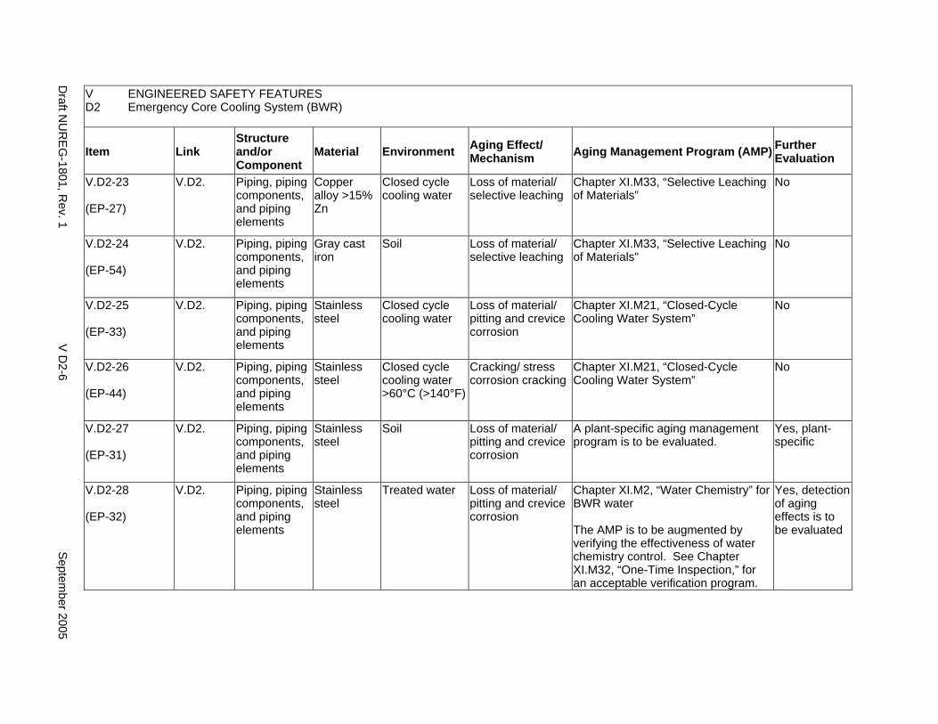
V ENGINEERED SAFETY FEATURES D2 Emergency Core Cooling System (BWR)
Item Link Structure and/or Component
Material Environment Aging Effect/ Mechanism Aging Management Program (AMP) Further
Evaluation
V.D2-23
(EP-27)
V.D2. Piping, piping components, and piping elements
Copper alloy >15% Zn
Closed cycle cooling water
Loss of material/ selective leaching
Chapter XI.M33, “Selective Leaching of Materials”
No
V.D2-24
(EP-54)
V.D2. Piping, piping components, and piping elements
Gray cast iron
Soil Loss of material/ selective leaching
Chapter XI.M33, “Selective Leaching of Materials"
No
V.D2-25
(EP-33)
V.D2. Piping, piping components, and piping elements
Stainless steel
Closed cycle cooling water
Loss of material/ pitting and crevice corrosion
Chapter XI.M21, “Closed-Cycle Cooling Water System”
No
V.D2-26
(EP-44)
V.D2. Piping, piping components, and piping elements
Stainless steel
Closed cycle cooling water >60°C (>140°F)
Cracking/ stress corrosion cracking
Chapter XI.M21, “Closed-Cycle Cooling Water System”
No
V.D2-27
(EP-31)
V.D2. Piping, piping components, and piping elements
Stainless steel
Soil Loss of material/ pitting and crevice corrosion
A plant-specific aging management program is to be evaluated.
Yes, plant-specific
V.D2-28
(EP-32)
V.D2. Piping, piping components, and piping elements
Stainless steel
Treated water Loss of material/ pitting and crevice corrosion
Chapter XI.M2, “Water Chemistry” for BWR water
The AMP is to be augmented by verifying the effectiveness of water chemistry control. See Chapter XI.M32, “One-Time Inspection,” for an acceptable verification program.
Yes, detection of aging effects is to be evaluated
Draft N
UR
EG
-1801, Rev. 1
V D
2-6 S
eptember 2005
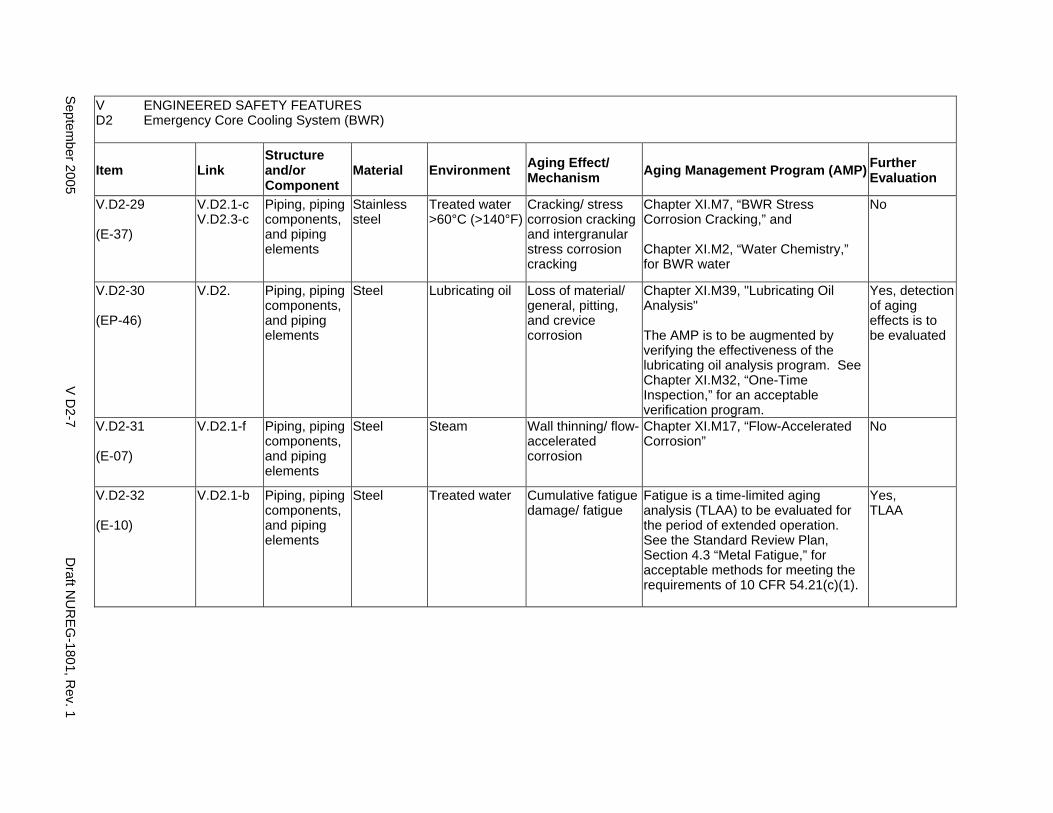
V ENGINEERED SAFETY FEATURES D2 Emergency Core Cooling System (BWR)
Item Link Structure and/or Component
Material Environment Aging Effect/ Mechanism Aging Management Program (AMP) Further
Evaluation
V.D2-29
(E-37)
V.D2.1-c V.D2.3-c
Piping, piping components, and piping elements
Stainless steel
Treated water >60°C (>140°F)
Cracking/ stress corrosion cracking and intergranular stress corrosion cracking
Chapter XI.M7, “BWR Stress Corrosion Cracking,” and
Chapter XI.M2, “Water Chemistry,” for BWR water
No
V.D2-30
(EP-46)
V.D2. Piping, piping components, and piping elements
Steel Lubricating oil Loss of material/ general, pitting, and crevice corrosion
Chapter XI.M39, "Lubricating Oil Analysis"
The AMP is to be augmented by verifying the effectiveness of the lubricating oil analysis program. See Chapter XI.M32, “One-Time Inspection,” for an acceptable verification program.
Yes, detection of aging effects is to be evaluated
V.D2-31
(E-07)
V.D2.1-f Piping, piping components, and piping elements
Steel Steam Wall thinning/ flow-accelerated corrosion
Chapter XI.M17, “Flow-Accelerated Corrosion”
No
V.D2-32
(E-10)
V.D2.1-b Piping, piping components, and piping elements
Steel Treated water Cumulative fatigue damage/ fatigue
Fatigue is a time-limited aging analysis (TLAA) to be evaluated for the period of extended operation. See the Standard Review Plan, Section 4.3 “Metal Fatigue,” for acceptable methods for meeting the requirements of 10 CFR 54.21(c)(1).
Yes, TLAA
Septem
ber 2005 V
D2-7
Draft N
UR
EG
-1801, Rev. 1
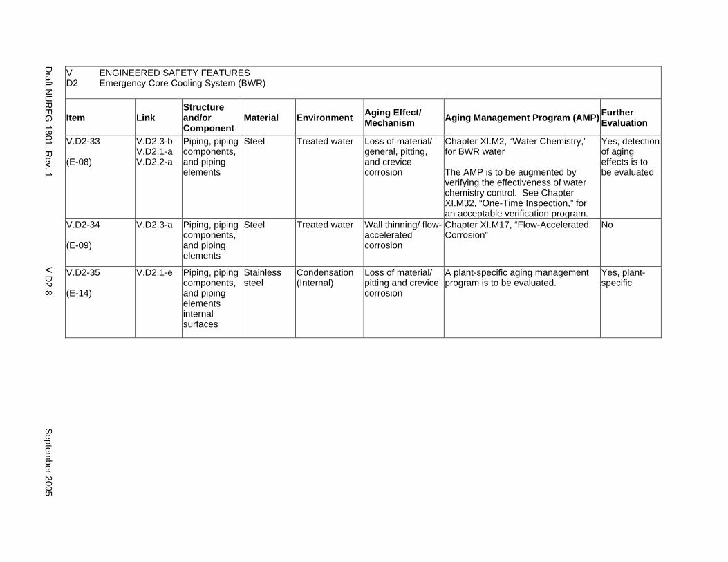
V ENGINEERED SAFETY FEATURES D2 Emergency Core Cooling System (BWR)
Item Link Structure and/or Component
Material Environment Aging Effect/ Mechanism Aging Management Program (AMP) Further
Evaluation
V.D2-33
(E-08)
V.D2.3-b V.D2.1-a V.D2.2-a
Piping, piping components, and piping elements
Steel Treated water Loss of material/ general, pitting, and crevice corrosion
Chapter XI.M2, “Water Chemistry,” for BWR water
The AMP is to be augmented by verifying the effectiveness of water chemistry control. See Chapter XI.M32, “One-Time Inspection,” for an acceptable verification program.
Yes, detection of aging effects is to be evaluated
V.D2-34
(E-09)
V.D2.3-a Piping, piping components, and piping elements
Steel Treated water Wall thinning/ flow-accelerated corrosion
Chapter XI.M17, “Flow-Accelerated Corrosion”
No
V.D2-35
(E-14)
V.D2.1-e Piping, piping components, and piping elements internal surfaces
Stainless steel
Condensation (Internal)
Loss of material/ pitting and crevice corrosion
A plant-specific aging management program is to be evaluated.
Yes, plant-specific
Draft N
UR
EG
-1801, Rev. 1
V D
2-8 S
eptember 2005
E. EXTERNAL SURFACES OF COMPONENTS AND MISCELLANEOUS BOLTING
Systems, Structures, and Components
This section addresses the aging management programs for the degradation of external surfaces of all steel structures and components including closure boltings in the engineered safety features in pressurized water reactors (PWRs) and boiling water reactors (BWRs). For the steel components in PWRs, this section addresses only boric acid corrosion of external surfaces as a result of dripping borated water leaking from an adjacent PWR component. Boric acid corrosion can also occur for steel components containing borated water due to leakage, such components and the related aging management program are covered in the appropriate major plant sections in V.
System Interfaces
The structures and components covered in this section belong to the engineered safety features in PWRs and BWRs. (For example, see System Interfaces in V.A to V.D2 for details.)
September 2005 V E-1 Draft NUREG-1801, Rev. 1
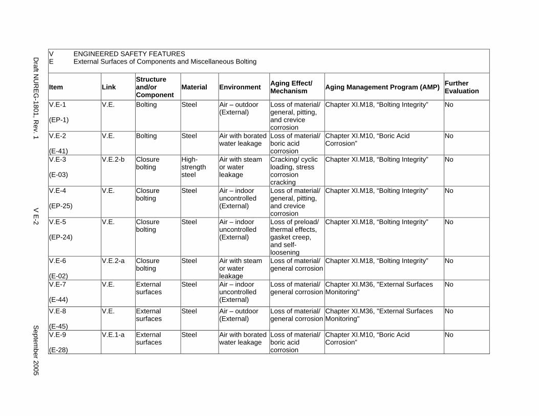
V ENGINEERED SAFETY FEATURES E External Surfaces of Components and Miscellaneous Bolting
Item Link Structure and/or Component
Material Environment Aging Effect/ Mechanism Aging Management Program (AMP) Further
Evaluation
V.E-1
(EP-1)
V.E. Bolting Steel Air – outdoor (External)
Loss of material/ general, pitting, and crevice corrosion
Chapter XI.M18, “Bolting Integrity” No
V.E-2
(E-41)
V.E. Bolting Steel Air with borated water leakage
Loss of material/ boric acid corrosion
Chapter XI.M10, “Boric Acid Corrosion”
No
V.E-3
(E-03)
V.E.2-b Closure bolting
High-strength steel
Air with steam or water leakage
Cracking/ cyclic loading, stress corrosion cracking
Chapter XI.M18, “Bolting Integrity” No
V.E-4
(EP-25)
V.E. Closure bolting
Steel Air – indoor uncontrolled (External)
Loss of material/ general, pitting, and crevice corrosion
Chapter XI.M18, “Bolting Integrity” No
V.E-5
(EP-24)
V.E. Closure bolting
Steel Air – indoor uncontrolled (External)
Loss of preload/ thermal effects, gasket creep, and self-loosening
Chapter XI.M18, “Bolting Integrity” No
V.E-6
(E-02)
V.E.2-a Closure bolting
Steel Air with steam or water leakage
Loss of material/ general corrosion
Chapter XI.M18, “Bolting Integrity” No
V.E-7
(E-44)
V.E. External surfaces
Steel Air – indoor uncontrolled (External)
Loss of material/ general corrosion
Chapter XI.M36, "External Surfaces Monitoring"
No
V.E-8
(E-45)
V.E. External surfaces
Steel Air – outdoor (External)
Loss of material/ general corrosion
Chapter XI.M36, "External Surfaces Monitoring"
No
V.E-9
(E-28)
V.E.1-a External surfaces
Steel Air with borated water leakage
Loss of material/ boric acid corrosion
Chapter XI.M10, “Boric Acid Corrosion”
No
Draft N
UR
EG
-1801, Rev. 1
V E
-2 S
eptember 2005
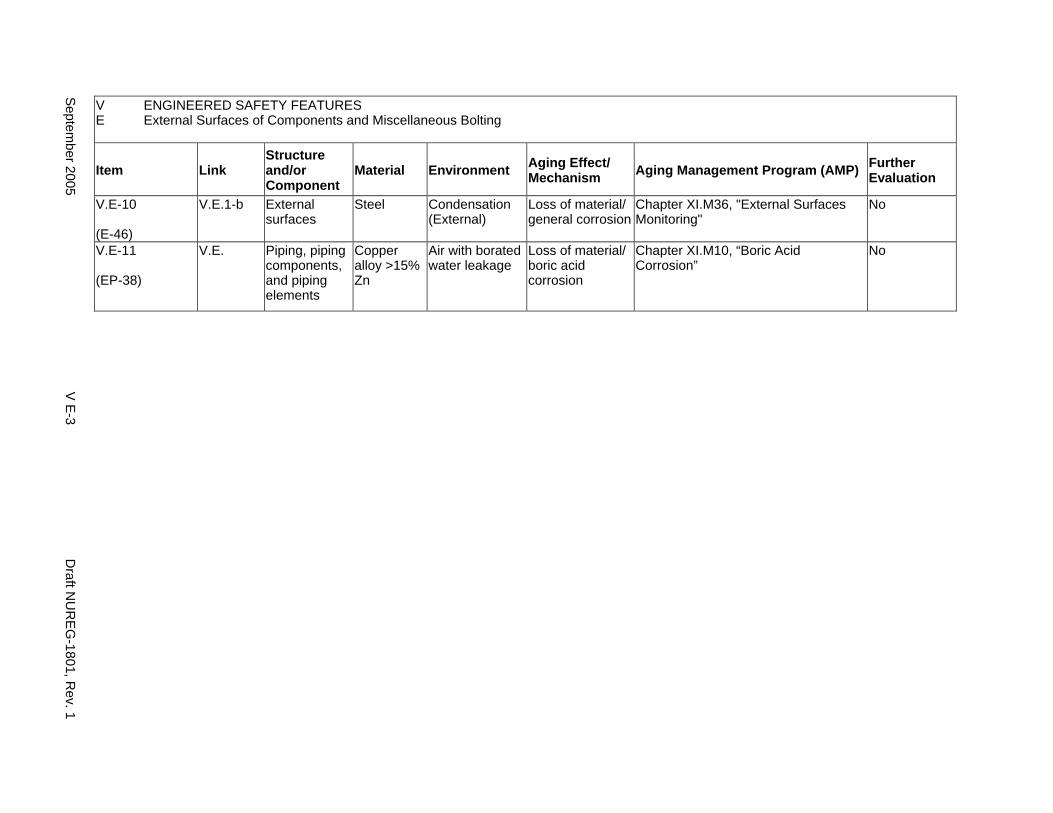
V ENGINEERED SAFETY FEATURES E External Surfaces of Components and Miscellaneous Bolting
Item Link Structure and/or Component
Material Environment Aging Effect/ Mechanism Aging Management Program (AMP) Further
Evaluation
V.E-10
(E-46)
V.E.1-b External surfaces
Steel Condensation (External)
Loss of material/ general corrosion
Chapter XI.M36, "External Surfaces Monitoring"
No
V.E-11
(EP-38)
V.E. Piping, piping components, and piping elements
Copper alloy >15% Zn
Air with borated water leakage
Loss of material/ boric acid corrosion
Chapter XI.M10, “Boric Acid Corrosion”
No
Septem
ber 2005 V
E-3
Draft N
UR
EG
-1801, Rev. 1
This Page Intentionally Left Blank
Draft NUREG-1801, Rev. 1 V E-4 September 2005
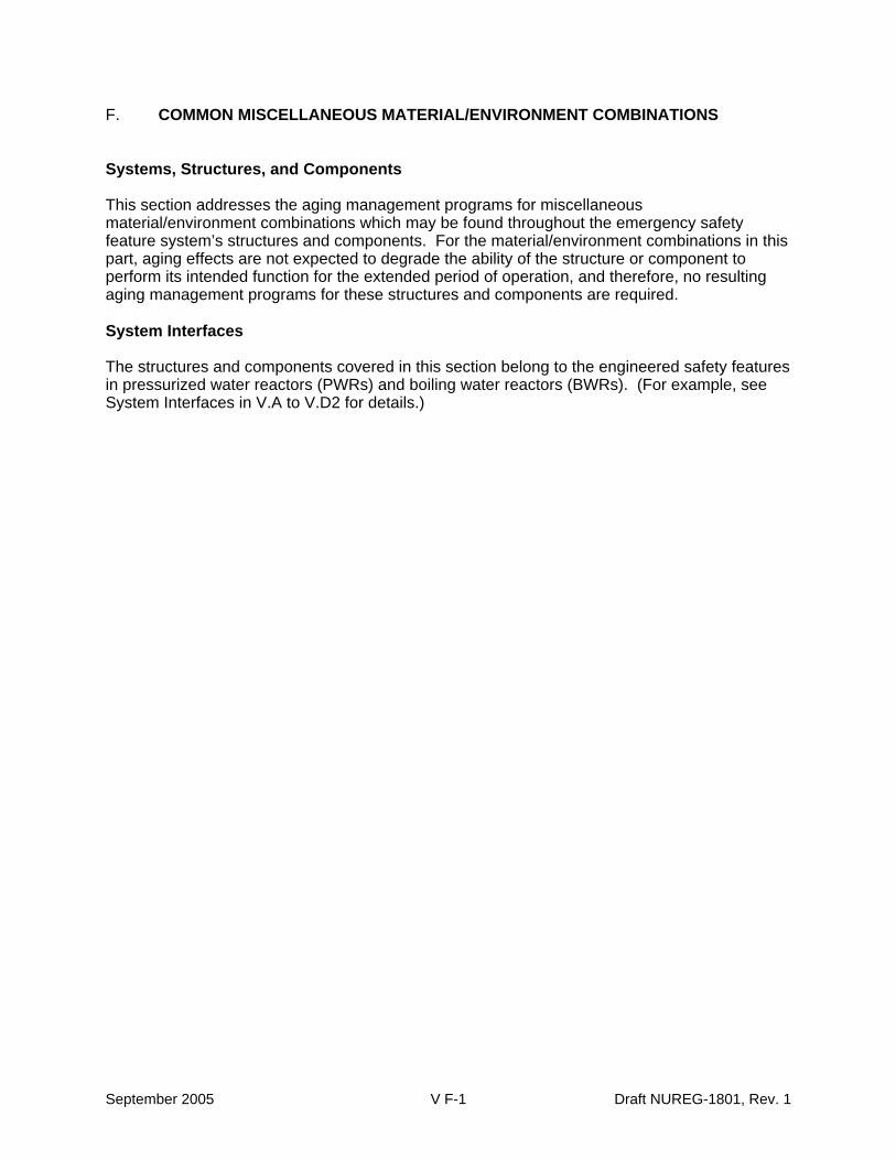
F. COMMON MISCELLANEOUS MATERIAL/ENVIRONMENT COMBINATIONS
Systems, Structures, and Components
This section addresses the aging management programs for miscellaneous material/environment combinations which may be found throughout the emergency safety feature system’s structures and components. For the material/environment combinations in this part, aging effects are not expected to degrade the ability of the structure or component to perform its intended function for the extended period of operation, and therefore, no resulting aging management programs for these structures and components are required.
System Interfaces
The structures and components covered in this section belong to the engineered safety features in pressurized water reactors (PWRs) and boiling water reactors (BWRs). (For example, see System Interfaces in V.A to V.D2 for details.)
September 2005 V F-1 Draft NUREG-1801, Rev. 1
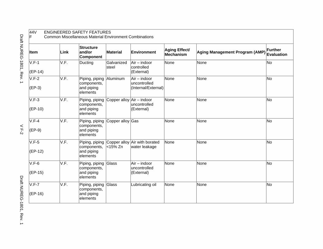
44V ENGINEERED SAFETY FEATURES F Common Miscellaneous Material Environment Combinations
Item Link Structure and/or Component
Material Environment Aging Effect/ Mechanism Aging Management Program (AMP) Further
Evaluation
V.F-1
(EP-14)
V.F. Ducting Galvanized steel
Air – indoor controlled (External)
None None No
V.F-2
(EP-3)
V.F. Piping, piping components, and piping elements
Aluminum Air – indoor uncontrolled (Internal/External)
None None No
V.F-3
(EP-10)
V.F. Piping, piping components, and piping elements
Copper alloy Air – indoor uncontrolled (External)
None None No
V.F-4
(EP-9)
V.F. Piping, piping components, and piping elements
Copper alloy Gas None None No
V.F-5
(EP-12)
V.F. Piping, piping components, and piping elements
Copper alloy <15% Zn
Air with borated water leakage
None None No
V.F-6
(EP-15)
V.F. Piping, piping components, and piping elements
Glass Air – indoor uncontrolled (External)
None None No
V.F-7
(EP-16)
V.F. Piping, piping components, and piping elements
Glass Lubricating oil None None No
Draft N
UR
EG
-1801, Rev. 1
V F-2
Draft N
UR
EG
-1801, Rev. 1
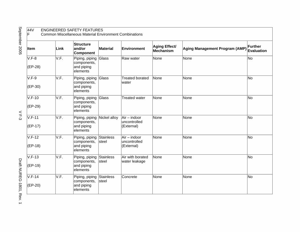
44V ENGINEERED SAFETY FEATURES F Common Miscellaneous Material Environment Combinations
Item Link Structure and/or Component
Material Environment Aging Effect/ Mechanism Aging Management Program (AMP) Further
Evaluation
V.F-8
(EP-28)
V.F. Piping, piping components, and piping elements
Glass Raw water None None No
V.F-9
(EP-30)
V.F. Piping, piping components, and piping elements
Glass Treated borated water
None None No
V.F-10
(EP-29)
V.F. Piping, piping components, and piping elements
Glass Treated water None None No
V.F-11
(EP-17)
V.F. Piping, piping components, and piping elements
Nickel alloy Air – indoor uncontrolled (External)
None None No
V.F-12
(EP-18)
V.F. Piping, piping components, and piping elements
Stainless steel
Air – indoor uncontrolled (External)
None None No
V.F-13
(EP-19)
V.F. Piping, piping components, and piping elements
Stainless steel
Air with borated water leakage
None None No
V.F-14
(EP-20)
V.F. Piping, piping components, and piping elements
Stainless steel
Concrete None None No
Septem
ber 2005 V
F-3 D
raft NU
RE
G-1801, R
ev. 1
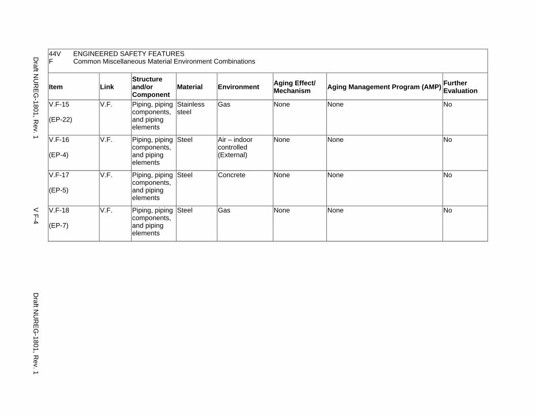
44V ENGINEERED SAFETY FEATURES F Common Miscellaneous Material Environment Combinations
Item Link Structure and/or Component
Material Environment Aging Effect/ Mechanism Aging Management Program (AMP) Further
Evaluation
V.F-15
(EP-22)
V.F. Piping, piping components, and piping elements
Stainless steel
Gas None None No
V.F-16
(EP-4)
V.F. Piping, piping components, and piping elements
Steel Air – indoor controlled (External)
None None No
V.F-17
(EP-5)
V.F. Piping, piping components, and piping elements
Steel Concrete None None No
V.F-18
(EP-7)
V.F. Piping, piping components, and piping elements
Steel Gas None None No
Draft N
UR
EG
-1801, Rev. 1
V F-4
Draft N
UR
EG
-1801, Rev. 1
CHAPTER VI
ELECTRICAL COMPONENTS
September 2005 VI-i Draft NUREG-1801, Rev. 1

This Page Intentionally Left Blank
Draft NUREG-1801, Rev. 1 VI-ii September 2005
ELECTRICAL COMPONENTS
A. Equipment Not Subject to 10 CFR 50.49 Environmental Qualification Requirements
B. Equipment Subject to 10 CFR 50.49 Environmental Qualification Requirements
September 2005 VI-iii Draft NUREG-1801, Rev. 1

This Page Intentionally Left Blank
Draft NUREG-1801, Rev. 1 VI-iv September 2005
A. EQUIPMENT NOT SUBJECT TO 10 CFR 50.49 ENVIRONMENTAL QUALIFICATION REQUIREMENTS
Systems, Structures and Components
This section addresses electrical cables and connections that are not subject to the environmental qualification requirements of 10 CFR 50.49, and that are installed in power and instrumentation and control (I&C) applications. The power cables and connections addressed are low-voltage (<1000V) and medium-voltage (2 kV to 35 kV). High voltage (>35 kV) power cables and connections have unique, specialized constructions and must be evaluated on an application specific basis.
This section also addresses components that are relied upon to meet the station blackout (SBO) requirements for restoration of offsite power. The plant system portion of the offsite power system that is used to connect the plant to the offsite power source is included in the SBO restoration equipment scope. This path typically includes the switchyard circuit breakers that connect to the offsite system power transformers (startup transformers), the transformers themselves, the intervening overhead or underground circuits between circuit breaker and transformer and transformer and onsite electrical distribution system (including bus ducts or cables), and associated control circuits and structures.
Electrical cables and their required terminations (i.e., connections) are typically reviewed as a single commodity. The types of connections included in this review are splices, mechanical connectors, fuse holders, and terminal blocks. This common review is translated into program actions, which treat cables and connections in the same manner.
Electrical cables and connections that are in the plant’s environmental qualification (EQ) program are addressed in VI.B.
System Interfaces
Electrical cables and connections functionally interface with all plant systems that rely on electric power or instrumentation and control. Electrical cables and connections also interface with and are supported by structural commodities (e.g., cable trays, conduit, cable trenches, cable troughs, duct banks, cable vaults and manholes) that are reviewed, as appropriate, in the Structures and Components Supports section.
September 2005 VI A-1 Draft NUREG-1801, Rev. 1
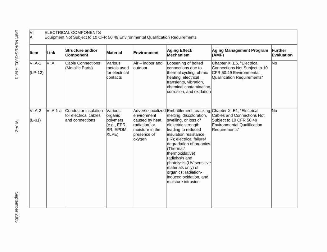
VI ELECTRICAL COMPONENTS A Equipment Not Subject to 10 CFR 50.49 Environmental Qualification Requirements
Item Link Structure and/or Component Material Environment Aging Effect/
Mechanism Aging Management Program (AMP)
Further Evaluation
VI.A-1
(LP-12)
VI.A. Cable Connections (Metallic Parts)
Various metals used for electrical contacts
Air – indoor and outdoor
Loosening of bolted connections due to thermal cycling, ohmic heating, electrical transients, vibration, chemical contamination, corrosion, and oxidation
Chapter XI.E6, "Electrical Connections Not Subject to 10 CFR 50.49 Environmental Qualification Requirements"
No
VI.A-2
(L-01)
VI.A.1-a Conductor insulation for electrical cables and connections
Various organic polymers (e.g., EPR, SR, EPDM, XLPE)
Adverse localized environment caused by heat, radiation, or moisture in the presence of oxygen
Embrittlement, cracking, melting, discoloration, swelling, or loss of dielectric strength leading to reduced insulation resistance (IR); electrical failure/ degradation of organics (Thermal/ thermoxidative), radiolysis and photolysis (UV sensitive materials only) of organics; radiation-induced oxidation, and moisture intrusion
Chapter XI.E1, “Electrical Cables and Connections Not Subject to 10 CFR 50.49 Environmental Qualification Requirements”
No
Draft N
UR
EG-1801, R
ev. 1 V
I A-2
Septem
ber 2005
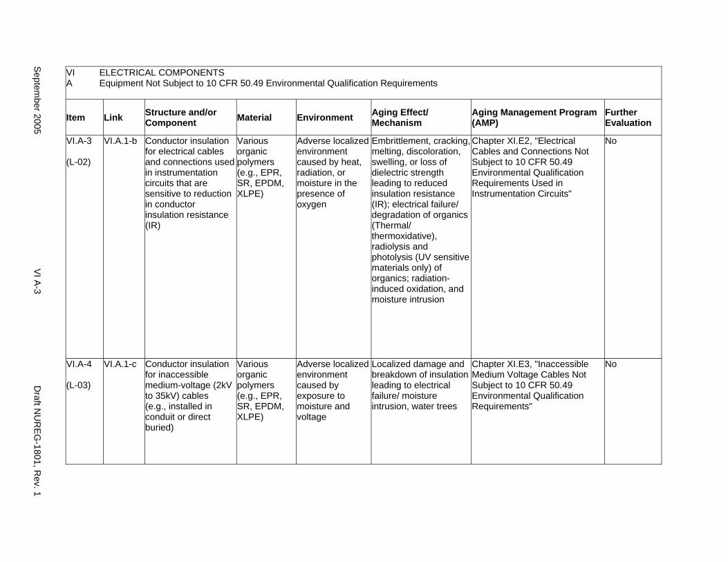
VI A
ELECTRICAL COMPONENTS Equipment Not Subject to 10 CFR 50.49 Environmental Qualification Requirements
Item Link Structure and/or Component Material Environment Aging Effect/
Mechanism Aging Management Program (AMP)
Further Evaluation
VI.A-3
(L-02)
VI.A.1-b Conductor insulation for electrical cables and connections used in instrumentation circuits that are sensitive to reduction in conductor insulation resistance (IR)
Various organic polymers (e.g., EPR, SR, EPDM, XLPE)
Adverse localized environment caused by heat, radiation, or moisture in the presence of oxygen
Embrittlement, cracking, melting, discoloration, swelling, or loss of dielectric strength leading to reduced insulation resistance (IR); electrical failure/ degradation of organics (Thermal/ thermoxidative), radiolysis and photolysis (UV sensitive materials only) of organics; radiation-induced oxidation, and moisture intrusion
Chapter XI.E2, "Electrical Cables and Connections Not Subject to 10 CFR 50.49 Environmental Qualification Requirements Used in Instrumentation Circuits"
No
VI.A-4
(L-03)
VI.A.1-c Conductor insulation for inaccessible medium-voltage (2kV to 35kV) cables (e.g., installed in conduit or direct buried)
Various organic polymers (e.g., EPR, SR, EPDM, XLPE)
Adverse localized environment caused by exposure to moisture and voltage
Localized damage and breakdown of insulation leading to electrical failure/ moisture intrusion, water trees
Chapter XI.E3, "Inaccessible Medium Voltage Cables Not Subject to 10 CFR 50.49 Environmental Qualification Requirements"
No
Septem
ber 2005 V
I A-3
Draft N
UR
EG-1801, R
ev. 1

VI ELECTRICAL COMPONENTS A Equipment Not Subject to 10 CFR 50.49 Environmental Qualification Requirements
Item Link Structure and/or Component Material Environment Aging Effect/
Mechanism Aging Management Program (AMP)
Further Evaluation
VI.A-5
(L-04)
VI.A.2-a Connector contacts for electrical connectors exposed to borated water leakage
Various metals used for electrical contacts
Air with borated water leakage
Corrosion of connector contact surfaces/ intrusion of borated water
Chapter XI.M10, “Boric Acid Corrosion”
No
VI.A-6
(LP-03)
VI.A. Fuse Holders (Not Part of a Larger Assembly); Insulation
Insulation material – bakelite, phenolic melamine or ceramic, molded polycarbonate and other
Adverse localized environment caused by heat, radiation, or moisture in the presence of oxygen or > 60-year service limiting temperature
Embrittlement, cracking, melting, discoloration, swelling, or loss of dielectric strength leading to reduced insulation resistance (IR); electrical failure/ degradation (Thermal/ thermoxidative) of organics/thermoplastics, radiation-induced oxidation, moisture intrusion and ohmic heating
Chapter XI.E1, “Electrical Cables and Connections Not Subject to 10 CFR 50.49 Environmental Qualification Requirements”
No
Draft N
UR
EG-1801, R
ev. 1 V
I A-4
Septem
ber 2005
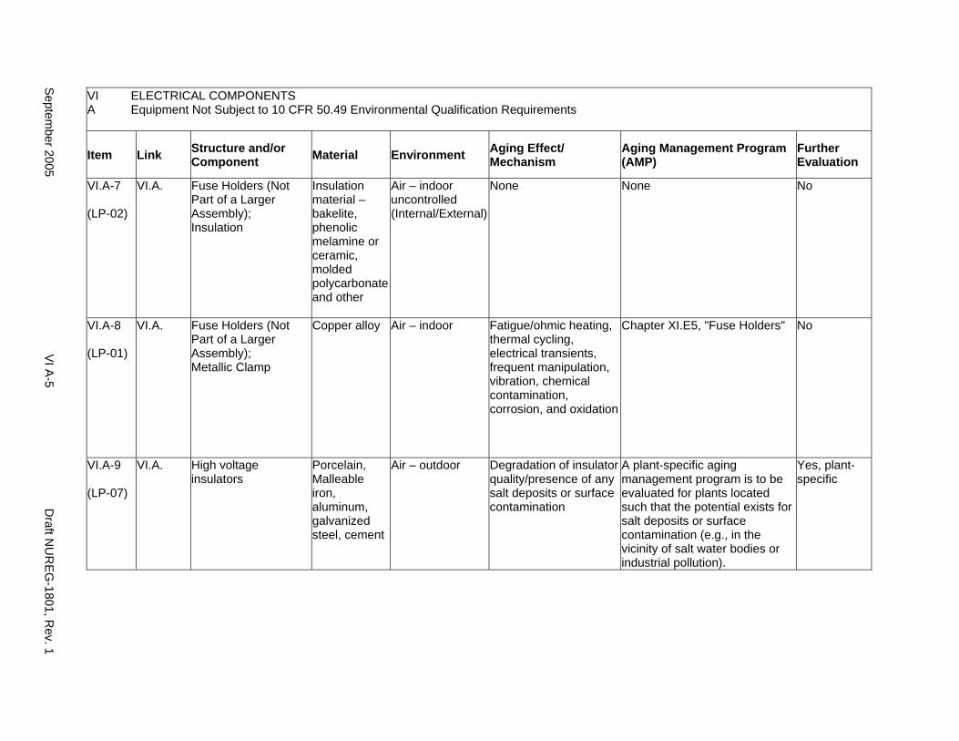
VI A
ELECTRICAL COMPONENTS Equipment Not Subject to 10 CFR 50.49 Environmental Qualification Requirements
Item Link Structure and/or Component Material Environment Aging Effect/
Mechanism Aging Management Program (AMP)
Further Evaluation
VI.A-7
(LP-02)
VI.A. Fuse Holders (Not Part of a Larger Assembly); Insulation
Insulation material – bakelite, phenolic melamine or ceramic, molded polycarbonate and other
Air – indoor uncontrolled (Internal/External)
None None No
VI.A-8
(LP-01)
VI.A. Fuse Holders (Not Part of a Larger Assembly); Metallic Clamp
Copper alloy Air – indoor Fatigue/ohmic heating, thermal cycling, electrical transients, frequent manipulation, vibration, chemical contamination, corrosion, and oxidation
Chapter XI.E5, "Fuse Holders" No
VI.A-9
(LP-07)
VI.A. High voltage insulators
Porcelain, Malleable iron, aluminum, galvanized steel, cement
Air – outdoor Degradation of insulator quality/presence of any salt deposits or surface contamination
A plant-specific aging management program is to be evaluated for plants located such that the potential exists for salt deposits or surface contamination (e.g., in the vicinity of salt water bodies or industrial pollution).
Yes, plant-specific
Septem
ber 2005 V
I A-5
Draft N
UR
EG-1801, R
ev. 1
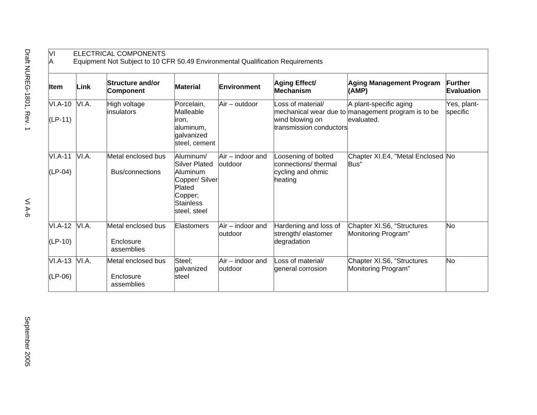
VI A
ELECTRICAL COMPONENTS Equipment Not Subject to 10 CFR 50.49 Environmental Qualification Requirements
Item Link Structure and/or Component Material Environment Aging Effect/
Mechanism Aging Management Program (AMP)
Further Evaluation
VI.A-10
(LP-11)
VI.A. High voltage insulators
Porcelain, Malleable iron, aluminum, galvanized steel, cement
Air – outdoor Loss of material/ mechanical wear due to wind blowing on transmission conductors
A plant-specific aging management program is to be evaluated.
Yes, plant-specific
VI.A-11
(LP-04)
VI.A. Metal enclosed bus
Bus/connections
Aluminum/ Silver Plated Aluminum Copper/ Silver Plated Copper; Stainless steel, steel
Air – indoor and outdoor
Loosening of bolted connections/ thermal cycling and ohmic heating
Chapter XI.E4, "Metal Enclosed Bus"
No
VI.A-12
(LP-10)
VI.A. Metal enclosed bus
Enclosure assemblies
Elastomers Air – indoor and outdoor
Hardening and loss of strength/ elastomer degradation
Chapter XI.S6, “Structures Monitoring Program”
No
VI.A-13
(LP-06)
VI.A. Metal enclosed bus
Enclosure assemblies
Steel; galvanized steel
Air – indoor and outdoor
Loss of material/ general corrosion
Chapter XI.S6, “Structures Monitoring Program”
No
Draft N
UR
EG-1801, R
ev. 1 V
I A-6
Septem
ber 2005
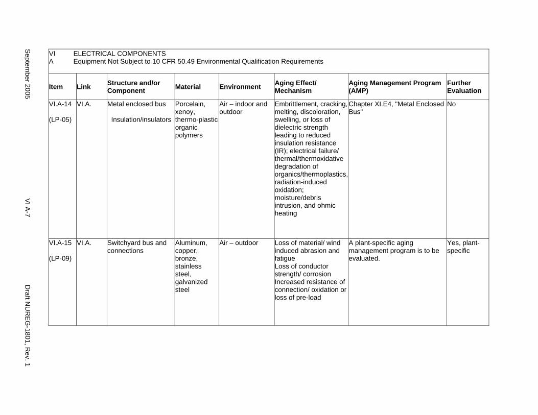
VI A
ELECTRICAL COMPONENTS Equipment Not Subject to 10 CFR 50.49 Environmental Qualification Requirements
Item Link Structure and/or Component Material Environment Aging Effect/
Mechanism Aging Management Program (AMP)
Further Evaluation
VI.A-14
(LP-05)
VI.A. Metal enclosed bus
Insulation/insulators
Porcelain, xenoy, thermo-plastic organic polymers
Air – indoor and outdoor
Embrittlement, cracking, melting, discoloration, swelling, or loss of dielectric strength leading to reduced insulation resistance (IR); electrical failure/ thermal/thermoxidative degradation of organics/thermoplastics, radiation-induced oxidation; moisture/debris intrusion, and ohmic heating
Chapter XI.E4, "Metal Enclosed Bus"
No
VI.A-15
(LP-09)
VI.A. Switchyard bus and connections
Aluminum, copper, bronze, stainless steel, galvanized steel
Air – outdoor Loss of material/ wind induced abrasion and fatigue Loss of conductor strength/ corrosion Increased resistance of connection/ oxidation or loss of pre-load
A plant-specific aging management program is to be evaluated.
Yes, plant-specific
Septem
ber 2005 V
I A-7
Draft N
UR
EG-1801, R
ev. 1
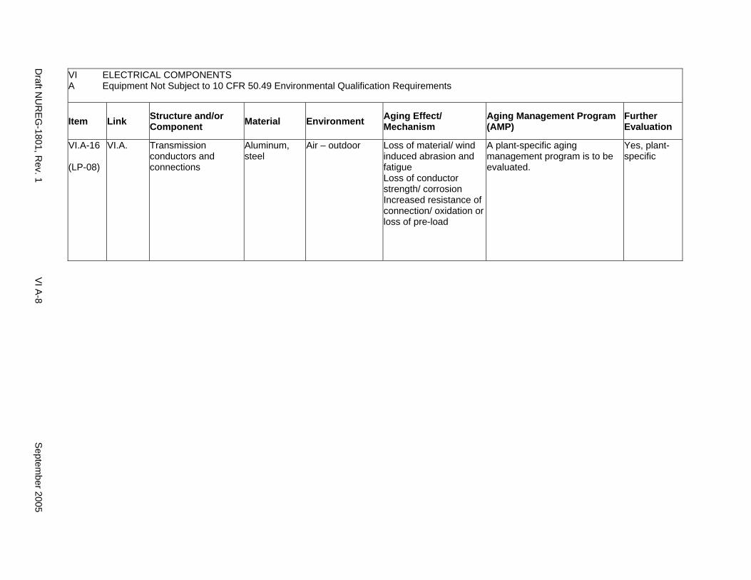
VI ELECTRICAL COMPONENTS A Equipment Not Subject to 10 CFR 50.49 Environmental Qualification Requirements
Item Link Structure and/or Component Material Environment Aging Effect/
Mechanism Aging Management Program (AMP)
Further Evaluation
VI.A-16
(LP-08)
VI.A. Transmission conductors and connections
Aluminum, steel
Air – outdoor Loss of material/ wind induced abrasion and fatigue Loss of conductor strength/ corrosion Increased resistance of connection/ oxidation or loss of pre-load
A plant-specific aging management program is to be evaluated.
Yes, plant-specific
Draft N
UR
EG-1801, R
ev. 1 V
I A-8
Septem
ber 2005
B. EQUIPMENT SUBJECT TO 10 CFR 50.49 ENVIRONMENTAL QUALIFICATION REQUIREMENTS
Systems, Structures and Components
The Nuclear Regulatory Commission (NRC) has established nuclear station environmental qualification (EQ) requirements in 10 CFR Part 50 Appendix A, Criterion 4, and in 10 CFR 50.49. 10 CFR 50.49 specifically requires that an EQ program be established to demonstrate that certain electrical components located in harsh plant environments (i.e., those areas of the plant that could be subject to the harsh environmental effects of a loss of coolant accident [LOCA], high energy line breaks [HELBs] or post-LOCA radiation) are qualified to perform their safety function in those harsh environments after the effects of inservice aging. 10 CFR 50.49 requires that the effects of significant aging mechanisms be addressed as part of environmental qualification. Components in the EQ program have a qualified life, and the components are replaced at the end of that qualified life, if it is shorter than the current operating term. The qualified life may be extended by methods such as refurbishment or reanalysis, but the licensee is required by the EQ regulation (10 CFR 50.49) to replace the component when its qualified life has expired.
Similarly, some nuclear power plants have mechanical equipment that was qualified in accordance with the provisions of Criterion 4 of Appendix A to 10 CFR Part 50.
System Interfaces
Equipment subject to 10 CFR 50.49 environmental qualification requirements functionally interfaces with all plant systems that rely on electric power or instrumentation and control.
September 2005 VI B-1 Draft NUREG-1801, Rev. 1
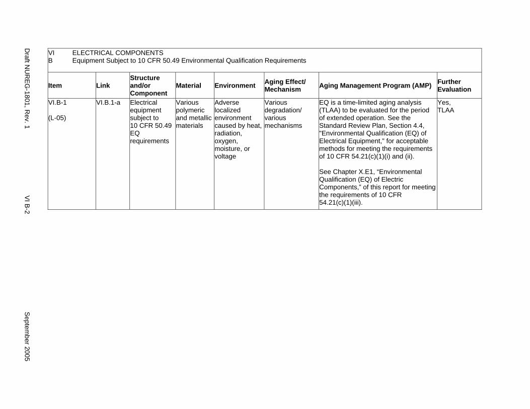
VI B
ELECTRICAL COMPONENTS Equipment Subject to 10 CFR 50.49 Environmental Qualification Requirements
Item Link Structure and/or Component
Material Environment Aging Effect/ Mechanism Aging Management Program (AMP) Further
Evaluation
VI.B-1
(L-05)
VI.B.1-a Electrical equipment subject to 10 CFR 50.49 EQ requirements
Various polymeric and metallic materials
Adverse localized environment caused by heat, radiation, oxygen, moisture, or voltage
Various degradation/ various mechanisms
EQ is a time-limited aging analysis (TLAA) to be evaluated for the period of extended operation. See the Standard Review Plan, Section 4.4, "Environmental Qualification (EQ) of Electrical Equipment," for acceptable methods for meeting the requirements of 10 CFR 54.21(c)(1)(i) and (ii).
See Chapter X.E1, “Environmental Qualification (EQ) of Electric Components,” of this report for meeting the requirements of 10 CFR 54.21(c)(1)(iii).
Yes, TLAA
Draft N
UR
EG-1801, R
ev. 1 V
I B-2
Septem
ber 2005
CHAPTER VII
AUXILIARY SYSTEMS
September 2005 VII-i Draft NUREG-1801, Rev. 1

This Page Intentionally Left Blank
Draft NUREG-1801, Rev. 1 VII-ii September 2005
MAJOR PLANT SECTIONS
A1. New Fuel Storage
A2. Spent Fuel Storage
A3. Spent Fuel Pool Cooling and Cleanup (PWR)
A4. Spent Fuel Pool Cooling and Cleanup (BWR)
A5. Suppression Pool Cleanup System (BWR)
B. Overhead Heavy Load and Light Load (Related to Refueling) Handling Systems
C1. Open-Cycle Cooling Water System (Service Water System)
C2. Closed-Cycle Cooling Water System
C3. Ultimate Heat Sink
D. Compressed Air System
E1. Chemical and Volume Control System (PWR)
E2. Standby Liquid Control System (BWR)
E3. Reactor Water Cleanup System (BWR)
E4. Shutdown Cooling System (Older BWR)
F1. Control Room Area Ventilation System
F2. Auxiliary and Radwaste Area Ventilation System
F3. Primary Containment Heating and Ventilation System
F4. Diesel Generator Building Ventilation System
G. Fire Protection
H1. Diesel Fuel Oil System
H2. Emergency Diesel Generator System
I. External Surfaces of Components and Miscellaneous Bolting
J. Common Miscellaneous Material/Environment Combinations
September 2005 VII-iii Draft NUREG-1801, Rev. 1

This Page Intentionally Left Blank
Draft NUREG-1801, Rev. 1 VII-iv September 2005
A1. NEW FUEL STORAGE
Systems, Structures, and Components
This section discusses those structures and components used for new fuel storage which include carbon steel new fuel storage racks located in the auxiliary building or the fuel handling building. The racks are exposed to the temperature and humidity in the auxiliary building. The racks are generally painted with a protective coating. Based on Regulatory Guide 1.26, “Quality Group Classifications and Standards for Water-, Steam-, and Radioactive-Waste-Containing Components of Nuclear Power Plants,” all components used for new fuel storage are governed by Group C Quality Standards.
Aging management programs for the degradation of external surfaces of components and miscellaneous bolting are included in VII.I. Common miscellaneous material/environment combinations where aging effects are not expected to degrade the ability of the structure or component to perform its intended function for the extended period of operation are included in VII.J.
System Interfaces
No other systems discussed in this report interface with those used for new fuel storage.
September 2005 VII A1-1 Draft NUREG-1801, Rev. 1
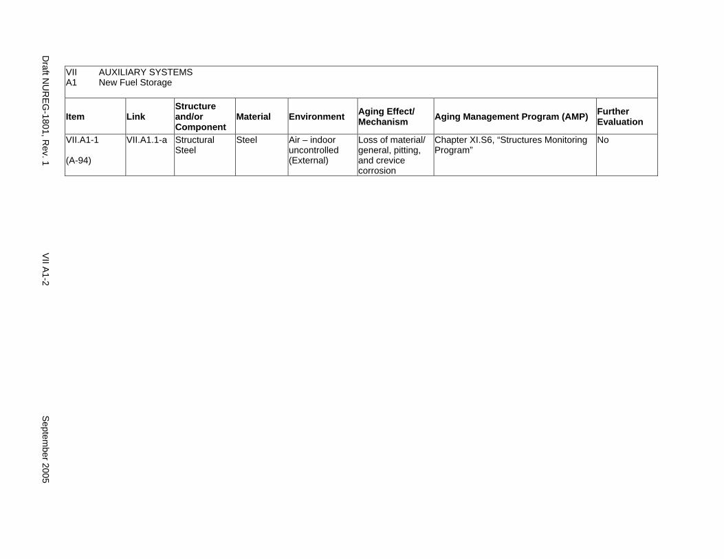
VII AUXILIARY SYSTEMS A1 New Fuel Storage
Item Link Structure and/or Component
Material Environment Aging Effect/ Mechanism Aging Management Program (AMP) Further
Evaluation
VII.A1-1
(A-94)
VII.A1.1-a Structural Steel
Steel Air – indoor uncontrolled (External)
Loss of material/ general, pitting, and crevice corrosion
Chapter XI.S6, “Structures Monitoring Program”
No
Draft N
UR
EG
-1801, Rev. 1
VII A
1-2 S
eptember 2005
A2. SPENT FUEL STORAGE
Systems, Structures, and Components
This section discusses those structures and components used for spent fuel storage and include stainless steel spent fuel storage racks and neutron absorbing materials (e.g., Boraflex, Boral, or boron-steel sheets, if used) submerged in chemically treated oxygenated boiling water reactor (BWR) or borated pressurized water reactor (PWR) water. The intended function of a spent fuel rack is to separate spent fuel assemblies. Boraflex sheets fastened to the storage cells provide for neutron absorption and help maintain subcriticality of spent fuel assemblies in the spent fuel pool.
Based on Regulatory Guide 1.26, “Quality Group Classifications and Standards for Water-, Steam-, and Radioactive-Waste-Containing Components of Nuclear Power Plants,” all components used for spent fuel storage are governed by Group C Quality Standards. In some plants, the Boraflex has been replaced by Boral or boron steel.
Aging management programs for the degradation of external surfaces of components and miscellaneous bolting are included in VII.I. Common miscellaneous material/environment combinations where aging effects are not expected to degrade the ability of the structure or component to perform its intended function for the extended period of operation are included in VII.J.
System Interfaces
No other systems discussed in this report interface with those used for spent fuel storage.
September 2005 VII A2-1 Draft NUREG-1801, Rev. 1
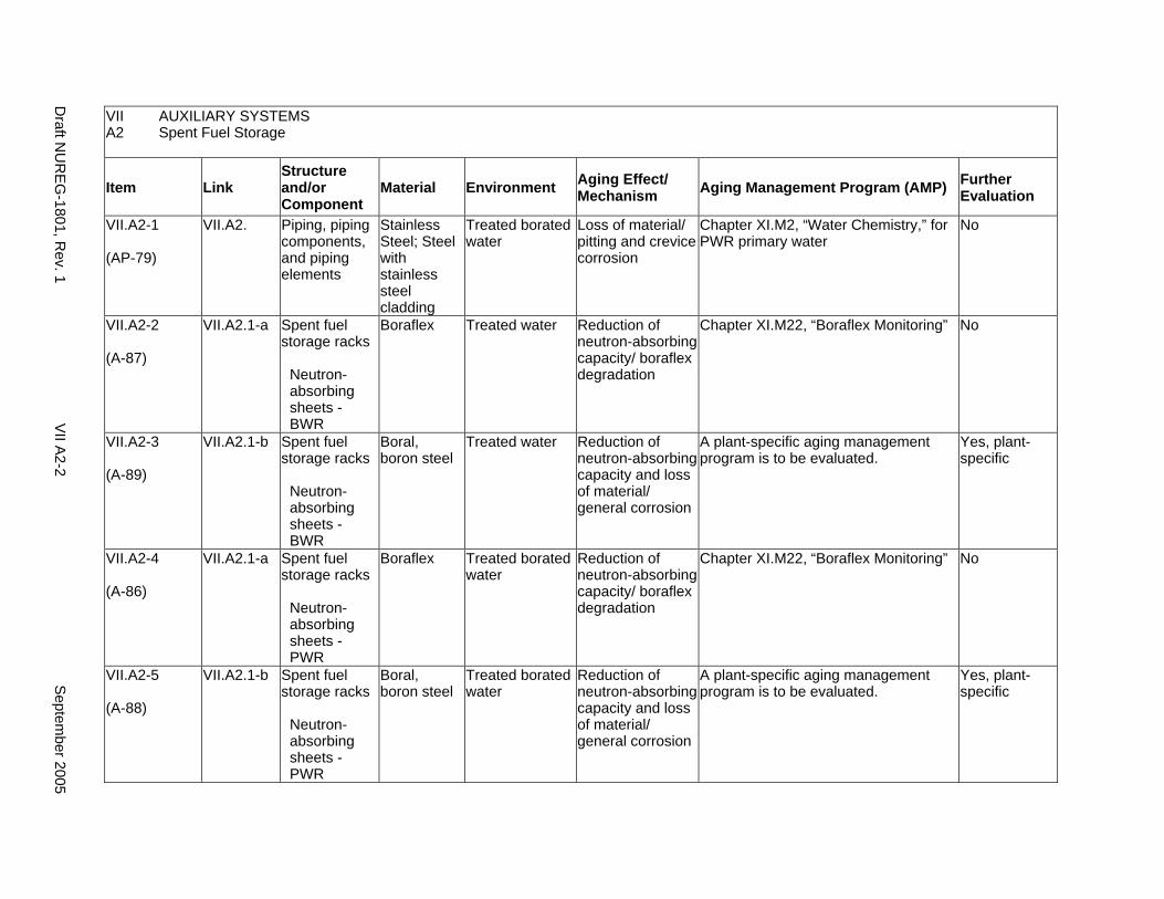
VII AUXILIARY SYSTEMS A2 Spent Fuel Storage
Item Link Structure and/or Component
Material Environment Aging Effect/ Mechanism Aging Management Program (AMP) Further
Evaluation
VII.A2-1
(AP-79)
VII.A2. Piping, piping components, and piping elements
Stainless Steel; Steel with stainless steel cladding
Treated borated water
Loss of material/ pitting and crevice corrosion
Chapter XI.M2, “Water Chemistry,” for PWR primary water
No
VII.A2-2
(A-87)
VII.A2.1-a Spent fuel storage racks
Neutron-absorbing sheets -BWR
Boraflex Treated water Reduction of neutron-absorbing capacity/ boraflex degradation
Chapter XI.M22, “Boraflex Monitoring” No
VII.A2-3
(A-89)
VII.A2.1-b Spent fuel storage racks
Neutron-absorbing sheets -BWR
Boral, boron steel
Treated water Reduction of neutron-absorbing capacity and loss of material/ general corrosion
A plant-specific aging management program is to be evaluated.
Yes, plant-specific
VII.A2-4
(A-86)
VII.A2.1-a Spent fuel storage racks
Neutron-absorbing sheets -PWR
Boraflex Treated borated water
Reduction of neutron-absorbing capacity/ boraflex degradation
Chapter XI.M22, “Boraflex Monitoring” No
VII.A2-5
(A-88)
VII.A2.1-b Spent fuel storage racks
Neutron-absorbing sheets -PWR
Boral, boron steel
Treated borated water
Reduction of neutron-absorbing capacity and loss of material/ general corrosion
A plant-specific aging management program is to be evaluated.
Yes, plant-specific
Draft N
UR
EG
-1801, Rev. 1
VII A
2-2 S
eptember 2005
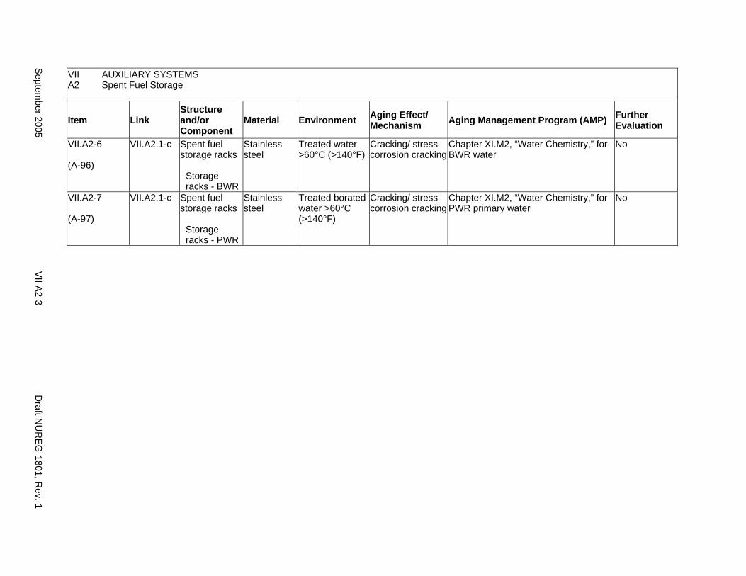
VII AUXILIARY SYSTEMS A2 Spent Fuel Storage
Item Link Structure and/or Component
Material Environment Aging Effect/ Mechanism Aging Management Program (AMP) Further
Evaluation
VII.A2-6
(A-96)
VII.A2.1-c Spent fuel storage racks
Storage racks - BWR
Stainless steel
Treated water >60°C (>140°F)
Cracking/ stress corrosion cracking
Chapter XI.M2, “Water Chemistry,” for BWR water
No
VII.A2-7
(A-97)
VII.A2.1-c Spent fuel storage racks
Storage racks - PWR
Stainless steel
Treated borated water >60°C (>140°F)
Cracking/ stress corrosion cracking
Chapter XI.M2, “Water Chemistry,” for PWR primary water
No
Septem
ber 2005 V
II A2-3
Draft N
UR
EG
-1801, Rev. 1

This Page Intentionally Left Blank
Draft NUREG-1801, Rev. 1 VII A2-4 September 2005
A3. SPENT FUEL POOL COOLING AND CLEANUP (PRESSURIZED WATER REACTOR)
Systems, Structures, and Components
This section discusses the pressurized water reactor (PWR) spent fuel pool cooling and cleanup system and consists of piping, valves, heat exchangers, filters, linings, demineralizers, and pumps. The system contains borated water. The system removes heat from the spent fuel pool and transfers heat to the closed-cycle cooling water system, which in turn transfers heat to the open-cycle cooling water system. Based on Regulatory Guide 1.26, “Quality Group Classifications and Standards for Water-, Steam-, and Radioactive-Waste-Containing Components of Nuclear Power Plants,” all components that comprise the PWR spent fuel pool cooling and cleanup system are governed by Group C Quality Standards.
With respect to filters, these items are to be addressed consistent with the Nuclear Regulatory Commission (NRC) position on consumables, provided in the NRC letter from Christopher I. Grimes to Douglas J. Walters of the Nuclear Energy Institute (NEI), dated March 10, 2000. Specifically, components that function as system filters are typically replaced based on performance or condition monitoring that identifies whether these components are at the end of their qualified lives and may be excluded, on a plant-specific basis, from an aging management review under 10 CFR 54.21(a)(1)(ii). As part of the methodology description, the application should identify the standards that are relied on for replacement, for example, National Fire Protection Association (NFPA) standards for fire protection equipment.
Pump and valve internals perform their intended functions with moving parts or with a change in configuration. They are also subject to replacement based on qualified life or specified time period. Pursuant to 10 CFR 54.21(a)(1), therefore, they are not subject to an aging management review.
Aging management programs for the degradation of external surfaces of components and miscellaneous bolting are included in VII.I. Common miscellaneous material/environment combinations where aging effects are not expected to degrade the ability of the structure or component to perform its intended function for the extended period of operation are included in VII.J.
The system piping includes all pipe sizes, including instrument piping.
System Interfaces
The systems that interface with the PWR spent fuel cooling and cleanup system are the PWR emergency core cooling system (V.D1), the closed-cycle cooling water system (VII.C2), and the PWR chemical and volume control system (VII.E1).
September 2005 VII A3-1 Draft NUREG-1801, Rev. 1

VII AUXILIARY SYSTEMS A3 Spent Fuel Pool Cooling and Cleanup (PWR)
Item Link Structure and/or Component
Material Environment Aging Effect/ Mechanism Aging Management Program (AMP) Further
Evaluation
VII.A3-1
(A-15)
VII.A3.3-a VII.A3.2-d VII.A3.5-c VII.A3.5-a VII.A3.3-d VII.A3.2-a
Elastomer lining
Elastomers Treated borated water
Hardening and loss of strength/ elastomer degradation
A plant-specific aging management program that determines and assesses the qualified life of the linings in the environment is to be evaluated.
Yes, plant-specific
VII.A3-2
(A-79)
VII.A3.1-a VII.A3.5-b VII.A3.3-c VII.A3.2-c VII.A3.2-b VII.A3.4-b VII.A3.6-a
External surfaces
Steel Air with borated water leakage
Loss of material/ boric acid corrosion
Chapter XI.M10, “Boric Acid Corrosion” No
VII.A3-3
(A-63)
VII.A3.4-a Heat exchanger components
Steel Closed cycle cooling water
Loss of material/ general, pitting, crevice, and galvanic corrosion
Chapter XI.M21, “Closed-Cycle Cooling Water System”
No
Draft N
UR
EG
-1801, Rev. 1
VII A
3-2 S
eptember 2005
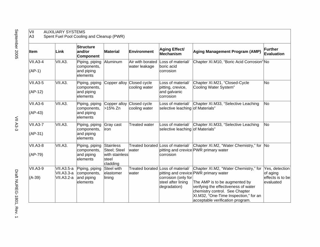
VII AUXILIARY SYSTEMS A3 Spent Fuel Pool Cooling and Cleanup (PWR)
Item Link Structure and/or Component
Material Environment Aging Effect/ Mechanism Aging Management Program (AMP) Further
Evaluation
VII.A3-4
(AP-1)
VII.A3. Piping, piping components, and piping elements
Aluminum Air with borated water leakage
Loss of material/ boric acid corrosion
Chapter XI.M10, “Boric Acid Corrosion” No
VII.A3-5
(AP-12)
VII.A3. Piping, piping components, and piping elements
Copper alloy Closed cycle cooling water
Loss of material/ pitting, crevice, and galvanic corrosion
Chapter XI.M21, “Closed-Cycle Cooling Water System”
No
VII.A3-6
(AP-43)
VII.A3. Piping, piping components, and piping elements
Copper alloy >15% Zn
Closed cycle cooling water
Loss of material/ selective leaching
Chapter XI.M33, “Selective Leaching of Materials”
No
VII.A3-7
(AP-31)
VII.A3. Piping, piping components, and piping elements
Gray cast iron
Treated water Loss of material/ selective leaching
Chapter XI.M33, “Selective Leaching of Materials”
No
VII.A3-8
(AP-79)
VII.A3. Piping, piping components, and piping elements
Stainless Steel; Steel with stainless steel cladding
Treated borated water
Loss of material/ pitting and crevice corrosion
Chapter XI.M2, “Water Chemistry,” for PWR primary water
No
VII.A3-9
(A-39)
VII.A3.5-a VII.A3.3-a VII.A3.2-a
Piping, piping components, and piping elements
Steel with elastomer lining
Treated borated water
Loss of material/ pitting and crevice corrosion (only for steel after lining degradation)
Chapter XI.M2, “Water Chemistry,” for PWR primary water
The AMP is to be augmented by verifying the effectiveness of water chemistry control. See Chapter XI.M32, “One-Time Inspection,” for an acceptable verification program.
Yes, detection of aging effects is to be evaluated
Septem
ber 2005 V
II A3-3
Draft N
UR
EG
-1801, Rev. 1
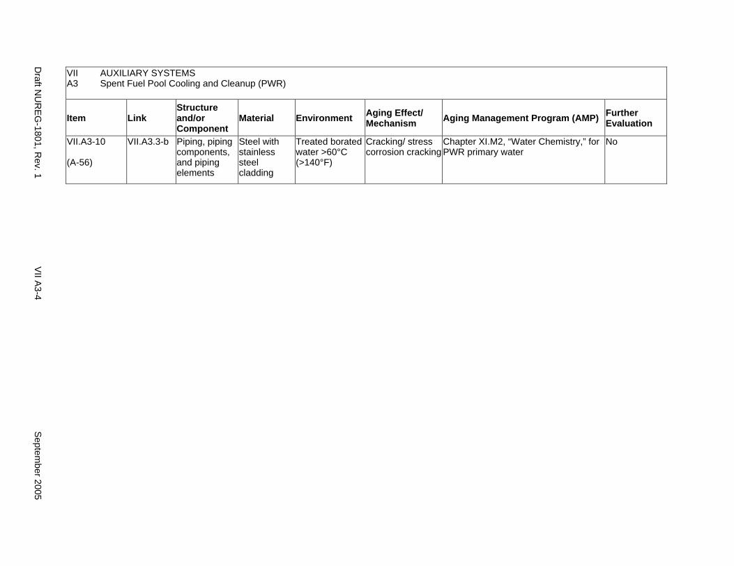
VII AUXILIARY SYSTEMS A3 Spent Fuel Pool Cooling and Cleanup (PWR)
Item Link Structure and/or Component
Material Environment Aging Effect/ Mechanism Aging Management Program (AMP) Further
Evaluation
VII.A3-10
(A-56)
VII.A3.3-b Piping, piping components, and piping elements
Steel with stainless steel cladding
Treated borated water >60°C (>140°F)
Cracking/ stress corrosion cracking
Chapter XI.M2, “Water Chemistry,” for PWR primary water
No
Draft N
UR
EG
-1801, Rev. 1
VII A
3-4 S
eptember 2005
A4. SPENT FUEL POOL COOLING AND CLEANUP (BOILING WATER REACTOR)
Systems, Structures, and Components
This section discusses the boiling water reactor (BWR) spent fuel pool cooling and cleanup system and consists of piping, valves, heat exchangers, filters, linings, demineralizers, and pumps. The system contains chemically treated oxygenated water. The system removes heat from the spent fuel pool, and transfers the heat to the closed-cycle cooling water system, which in turn transfers the heat to the open-cycle cooling water system. Based on Regulatory Guide 1.26, “Quality Group Classifications and Standards for Water-, Steam-, and Radioactive-Waste-Containing Components of Nuclear Power Plants,” all components that comprise the BWR spent fuel pool cooling and cleanup system are governed by Group C Quality Standards.
With respect to filters, these items are to be addressed consistent with the Nuclear Regulatory Commission (NRC) position on consumables, provided in the NRC letter from Christopher I. Grimes to Douglas J. Walters of the Nuclear Energy Institute (NEI), dated March 10, 2000. Specifically, components that function as system filters are typically replaced based on performance or condition monitoring that identifies whether these components are at the end of their qualified lives and may be excluded, on a plant-specific basis, from an aging management review under 10 CFR 54.21(a)(1)(ii). As part of the methodology description, the application should identify the standards that are relied on for replacement, for example, National Fire Protection Association (NFPA) standards for fire protection equipment.
Pump and valve internals perform their intended functions with moving parts or with a change in configuration. They are also subject to replacement based on qualified life or specified time period. Pursuant to 10 CFR 54.21(a)(1), therefore, they are not subject to an aging management review.
Aging management programs for the degradation of external surfaces of components and miscellaneous bolting are included in VII.I. Common miscellaneous material/environment combinations where aging effects are not expected to degrade the ability of the structure or component to perform its intended function for the extended period of operation are included in VII.J.
The system piping includes all pipe sizes, including instrument piping.
System Interfaces
The systems that interface with the BWR spent fuel cooling and cleanup system are the closed-cycle cooling water system (VII.C2) and the condensate system (VIII.E).
September 2005 VII A4-1 Draft NUREG-1801, Rev. 1
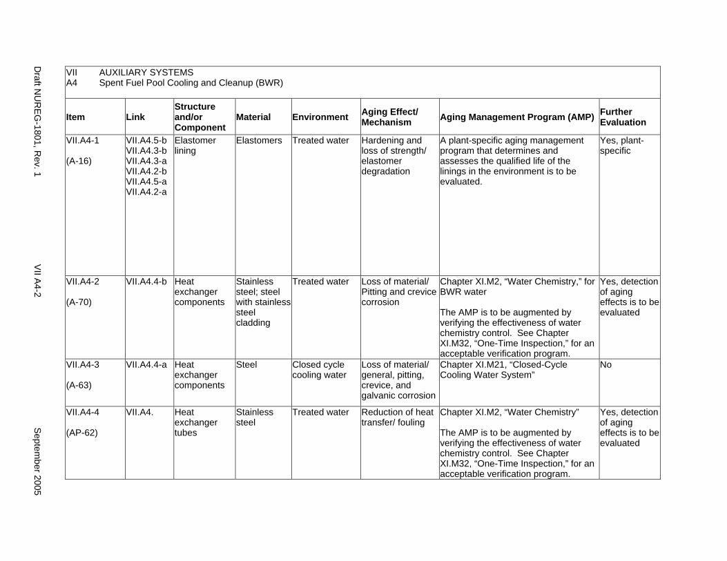
VII AUXILIARY SYSTEMS A4 Spent Fuel Pool Cooling and Cleanup (BWR)
Item Link Structure and/or Component
Material Environment Aging Effect/ Mechanism Aging Management Program (AMP) Further
Evaluation
VII.A4-1
(A-16)
VII.A4.5-b VII.A4.3-b VII.A4.3-a VII.A4.2-b VII.A4.5-a VII.A4.2-a
Elastomer lining
Elastomers Treated water Hardening and loss of strength/ elastomer degradation
A plant-specific aging management program that determines and assesses the qualified life of the linings in the environment is to be evaluated.
Yes, plant-specific
VII.A4-2
(A-70)
VII.A4.4-b Heat exchanger components
Stainless steel; steel with stainless steel cladding
Treated water Loss of material/ Pitting and crevice corrosion
Chapter XI.M2, “Water Chemistry,” for BWR water
The AMP is to be augmented by verifying the effectiveness of water chemistry control. See Chapter XI.M32, “One-Time Inspection,” for an acceptable verification program.
Yes, detection of aging effects is to be evaluated
VII.A4-3
(A-63)
VII.A4.4-a Heat exchanger components
Steel Closed cycle cooling water
Loss of material/ general, pitting, crevice, and galvanic corrosion
Chapter XI.M21, “Closed-Cycle Cooling Water System”
No
VII.A4-4
(AP-62)
VII.A4. Heat exchanger tubes
Stainless steel
Treated water Reduction of heat transfer/ fouling
Chapter XI.M2, “Water Chemistry”
The AMP is to be augmented by verifying the effectiveness of water chemistry control. See Chapter XI.M32, “One-Time Inspection,” for an acceptable verification program.
Yes, detection of aging effects is to be evaluated
Draft N
UR
EG
-1801, Rev. 1
VII A
4-2 S
eptember 2005
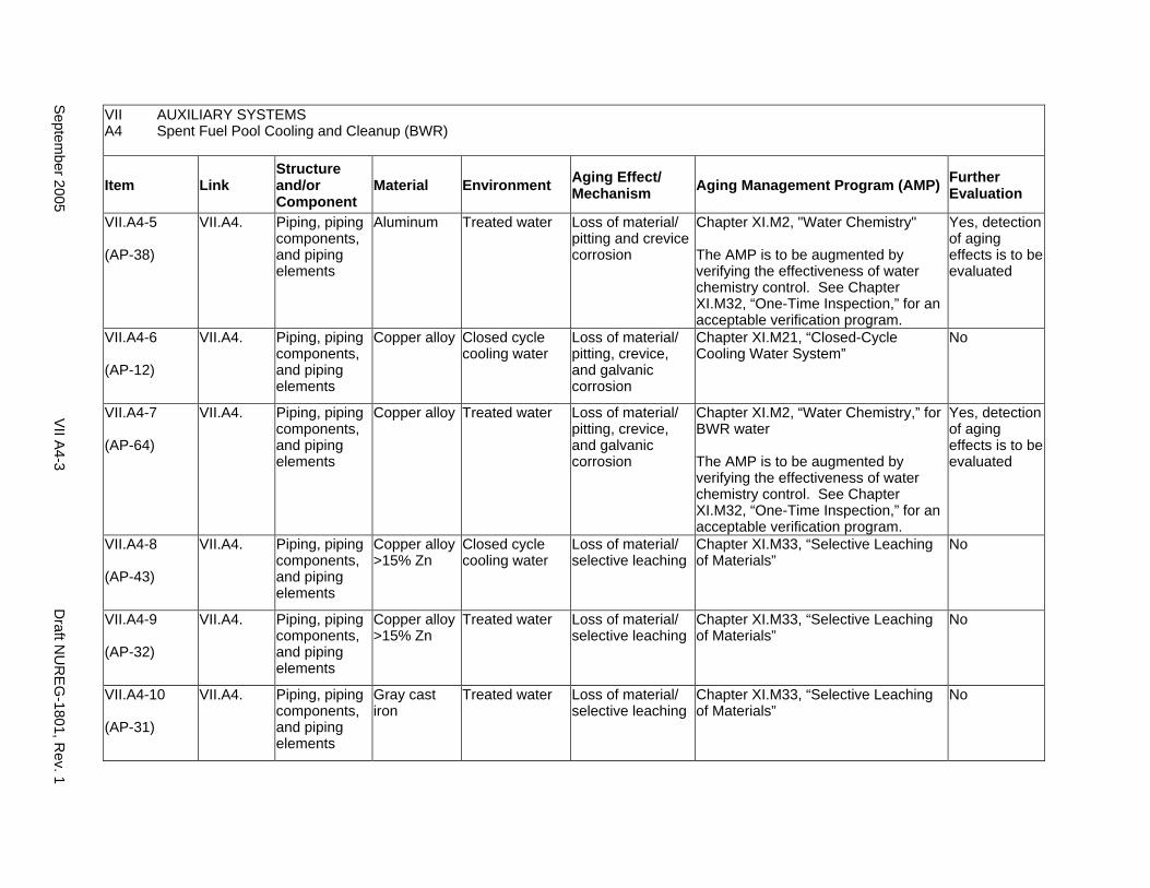
VII AUXILIARY SYSTEMS A4 Spent Fuel Pool Cooling and Cleanup (BWR)
Item Link Structure and/or Component
Material Environment Aging Effect/ Mechanism Aging Management Program (AMP) Further
Evaluation
VII.A4-5
(AP-38)
VII.A4. Piping, piping components, and piping elements
Aluminum Treated water Loss of material/ pitting and crevice corrosion
Chapter XI.M2, "Water Chemistry"
The AMP is to be augmented by verifying the effectiveness of water chemistry control. See Chapter XI.M32, “One-Time Inspection,” for an acceptable verification program.
Yes, detection of aging effects is to be evaluated
VII.A4-6
(AP-12)
VII.A4. Piping, piping components, and piping elements
Copper alloy Closed cycle cooling water
Loss of material/ pitting, crevice, and galvanic corrosion
Chapter XI.M21, “Closed-Cycle Cooling Water System”
No
VII.A4-7
(AP-64)
VII.A4. Piping, piping components, and piping elements
Copper alloy Treated water Loss of material/ pitting, crevice, and galvanic corrosion
Chapter XI.M2, “Water Chemistry,” for BWR water
The AMP is to be augmented by verifying the effectiveness of water chemistry control. See Chapter XI.M32, “One-Time Inspection,” for an acceptable verification program.
Yes, detection of aging effects is to be evaluated
VII.A4-8
(AP-43)
VII.A4. Piping, piping components, and piping elements
Copper alloy >15% Zn
Closed cycle cooling water
Loss of material/ selective leaching
Chapter XI.M33, “Selective Leaching of Materials”
No
VII.A4-9
(AP-32)
VII.A4. Piping, piping components, and piping elements
Copper alloy >15% Zn
Treated water Loss of material/ selective leaching
Chapter XI.M33, “Selective Leaching of Materials”
No
VII.A4-10
(AP-31)
VII.A4. Piping, piping components, and piping elements
Gray cast iron
Treated water Loss of material/ selective leaching
Chapter XI.M33, “Selective Leaching of Materials”
No
Septem
ber 2005 V
II A4-3
Draft N
UR
EG
-1801, Rev. 1
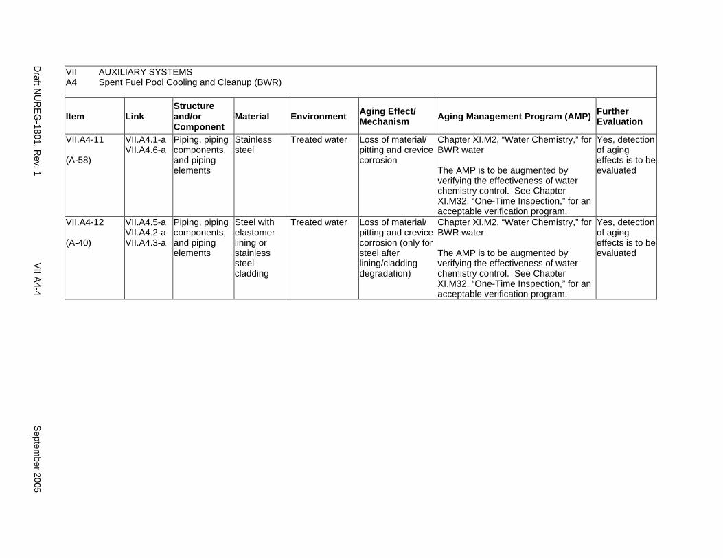
VII AUXILIARY SYSTEMS A4 Spent Fuel Pool Cooling and Cleanup (BWR)
Item Link Structure and/or Component
Material Environment Aging Effect/ Mechanism Aging Management Program (AMP) Further
Evaluation
VII.A4-11
(A-58)
VII.A4.1-a VII.A4.6-a
Piping, piping components, and piping elements
Stainless steel
Treated water Loss of material/ pitting and crevice corrosion
Chapter XI.M2, “Water Chemistry,” for BWR water
The AMP is to be augmented by verifying the effectiveness of water chemistry control. See Chapter XI.M32, “One-Time Inspection,” for an acceptable verification program.
Yes, detection of aging effects is to be evaluated
VII.A4-12
(A-40)
VII.A4.5-a VII.A4.2-a VII.A4.3-a
Piping, piping components, and piping elements
Steel with elastomer lining or stainless steel cladding
Treated water Loss of material/ pitting and crevice corrosion (only for steel after lining/cladding degradation)
Chapter XI.M2, “Water Chemistry,” for BWR water
The AMP is to be augmented by verifying the effectiveness of water chemistry control. See Chapter XI.M32, “One-Time Inspection,” for an acceptable verification program.
Yes, detection of aging effects is to be evaluated
Draft N
UR
EG
-1801, Rev. 1
VII A
4-4 S
eptember 2005
A5. SUPPRESSION POOL CLEANUP SYSTEM (BOILING WATER REACTOR)
Systems, Structures, and Components
This section discusses the suppression pool cleanup system, which maintains water quality in the suppression pool in boiling water reactors (BWRs). The components of this system include piping, filters, valves, and pumps. These components are fabricated of carbon, low-alloy, or austenitic stainless steel. Based on Regulatory Guide 1.26, “Quality Group Classifications and Standards for Water-, Steam-, and Radioactive-Waste-Containing Components of Nuclear Power Plants,” the components that comprise the suppression pool cleanup system are governed by the same Group C Quality Standards Group as the corresponding components in the spent fuel pool cooling and cleanup system (VII.A4).
Pump and valve internals perform their intended functions with moving parts or with a change in configuration. They are also subject to replacement based on qualified life or specified time period. Pursuant to 10 CFR 54.21(a)(1), therefore, they are not subject to an aging management review.
Aging management programs for the degradation of external surfaces of components and miscellaneous bolting are included in VII.I. Common miscellaneous material/environment combinations where aging effects are not expected to degrade the ability of the structure or component to perform its intended function for the extended period of operation are included in VII.J.
The system piping includes all pipe sizes, including instrument piping.
System Interfaces
The system that interfaces with the suppression pool cleanup system is the BWR containment (II.B), or BWR emergency core cooling system (V.D2).
Evaluation Summary
There are no tables associated with this section because the suppression pool cleanup system in BWRs is similar to the spent fuel pool cooling and cleanup system (VII.A4), and the components in the two systems are identical or very similar. Therefore, the reader is referred to the section for the spent fuel storage pool system for a listing of aging effects, aging mechanisms, and aging management programs that are to be applied to the suppression pool cleanup system components. (The only component in VII.A4 that may not be applicable to the suppression pool cleanup system is the heat exchanger [VII.A4.4].)
September 2005 VII A5-1 Draft NUREG-1801, Rev. 1

This Page Intentionally Left Blank
Draft NUREG-1801, Rev. 1 VII A5-2 September 2005
B. OVERHEAD HEAVY LOAD AND LIGHT LOAD (RELATED TO REFUELING) HANDLING SYSTEMS
Systems, Structures, and Components
Most commercial nuclear facilities have between fifty and one hundred cranes. Many of these cranes are industrial grade cranes that must meet the requirements of 29 CFR Volume XVII, Part 1910, and Section 1910.179. They do not fall within the scope of 10 CFR Part 54.4 and therefore are not required to be part of the integrated plant assessment (IPA). Normally fewer than ten cranes fall within the scope of 10 CFR Part 54.4. These cranes must comply with the requirements provided in 10 CFR Part 50.65 and Reg. Guide 1.160 for monitoring the effectiveness of maintenance at nuclear power plants.
The Inspection of Overhead Heavy Load and Light Load (Related to Refueling) Handling Systems (the Program) must demonstrate that the testing and the monitoring of the maintenance programs have been completed to ensure that the structures, systems, and components of these cranes are capable of sustaining their rated loads during the period of extended operation. The inspection is also to evaluate whether the usage of the cranes or hoists has been sufficient to warrant additional fatigue analysis. It should be noted that many of the systems and components of these cranes can be classified as moving parts or as components which change configuration, or they may be subject to replacement based on a qualified life. In any of these cases, they will not fall within the scope of this Aging Management Review (AMR). The primary components that this program is concerned with are the structural girders and beams that make up the bridge and the trolley.
Based on Regulatory Guide 1.26, “Quality Group Classifications and Standards for Water-, Steam-, and Radioactive-Waste-Containing Components of Nuclear Power Plants,” all components that comprise the overhead heavy load and light load handling systems are governed by Group C Quality Standards.
Aging management programs for the degradation of external surfaces of components and miscellaneous bolting are included in VII.I. Common miscellaneous material/environment combinations where aging effects are not expected to degrade the ability of the structure or component to perform its intended function for the extended period of operation are included in VII.J.
System Interfaces
No other systems discussed in this report interface with the overhead heavy load and light load (related to refueling) handling systems. Physical interfaces exist with the supporting structure. The direct interface is at the connection to the structure.
September 2005 VII B-1 Draft NUREG-1801, Rev. 1
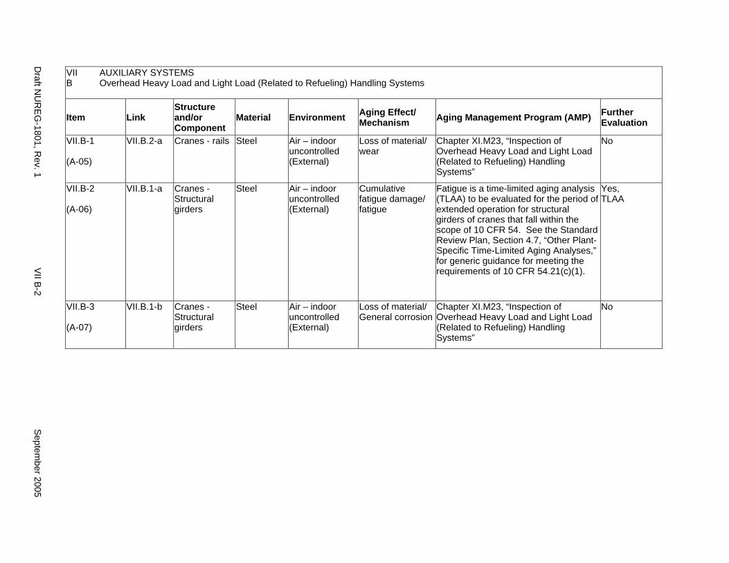
VII B
AUXILIARY SYSTEMS Overhead Heavy Load and Light Load (Related to Refueling) Handling Systems
Item Link Structure and/or Component
Material Environment Aging Effect/ Mechanism Aging Management Program (AMP) Further
Evaluation
VII.B-1
(A-05)
VII.B.2-a Cranes - rails Steel Air – indoor uncontrolled (External)
Loss of material/ wear
Chapter XI.M23, “Inspection of Overhead Heavy Load and Light Load (Related to Refueling) Handling Systems”
No
VII.B-2
(A-06)
VII.B.1-a Cranes - Structural girders
Steel Air – indoor uncontrolled (External)
Cumulative fatigue damage/ fatigue
Fatigue is a time-limited aging analysis (TLAA) to be evaluated for the period of extended operation for structural girders of cranes that fall within the scope of 10 CFR 54. See the Standard Review Plan, Section 4.7, “Other Plant-Specific Time-Limited Aging Analyses,” for generic guidance for meeting the requirements of 10 CFR 54.21(c)(1).
Yes, TLAA
VII.B-3
(A-07)
VII.B.1-b Cranes - Structural girders
Steel Air – indoor uncontrolled (External)
Loss of material/ General corrosion
Chapter XI.M23, “Inspection of Overhead Heavy Load and Light Load (Related to Refueling) Handling Systems”
No
Draft N
UR
EG
-1801, Rev. 1
VII B
-2 S
eptember 2005
C1. OPEN-CYCLE COOLING WATER SYSTEM (SERVICE WATER SYSTEM)
Systems, Structures, and Components
This section discusses the open-cycle cooling water (OCCW) (or service water) system, which consists of piping, heat exchangers, pumps, flow orifices, basket strainers, and valves, including containment isolation valves. Because the characteristics of an OCCW system may be unique to each facility, the OCCW system is defined as a system or systems that transfer heat from safety-related systems, structures, and components (SSCs) to the ultimate heat sink (UHS) such as a lake, ocean, river, spray pond, or cooling tower. The AMPs described in this section apply to any such system, provided the service conditions and materials of construction are identical to those identified in the section. The system removes heat from the closed-cycle cooling water system and, in some plants, other auxiliary systems and components such as steam turbine bearing oil coolers, or miscellaneous coolers in the condensate system. The only heat exchangers addressed in this section are those removing heat from the closed-cycle cooling system. Heat exchangers for removing heat from other auxiliary systems and components are addressed in their respective systems, such as those for the steam turbine bearing oil coolers (VIII.A) and for the condensate system coolers (VIII.E).
Based on Regulatory Guide 1.26, “Quality Group Classifications and Standards for Water-, Steam-, and Radioactive-Waste-Containing Components of Nuclear Power Plants,” all components that comprise the open-cycle cooling water system are governed by Group C Quality Standards, with the exception of those forming part of the containment penetration boundary which are governed by Group B Quality Standards.
Pump and valve internals perform their intended functions with moving parts or with a change in configuration. They are also subject to replacement based on qualified life or specified time period. Pursuant to 10 CFR 54.21(a)(1), therefore, they are not subject to an aging management review.
Aging management programs for the degradation of external surfaces of components and miscellaneous bolting are included in VII.I. Common miscellaneous material/environment combinations where aging effects are not expected to degrade the ability of the structure or component to perform its intended function for the extended period of operation are included in VII.J.
The system piping includes all pipe sizes, including instrument piping.
System Interfaces
The systems that may interface with the open-cycle cooling water system include the closed-cycle cooling water system (VII.C2), the ultimate heat sink (VII.C3), the emergency diesel generator system (VII.H2), the containment spray system (V.A), the PWR steam generator blowdown system (VIII.F), the condensate system (VIII.E), the auxiliary feedwater system (PWR) (VIII.G), the emergency core cooling system (PWR) (V.D1), and the emergency core cooling system (BWR) (V.D2).
September 2005 VII C1-1 Draft NUREG-1801, Rev. 1
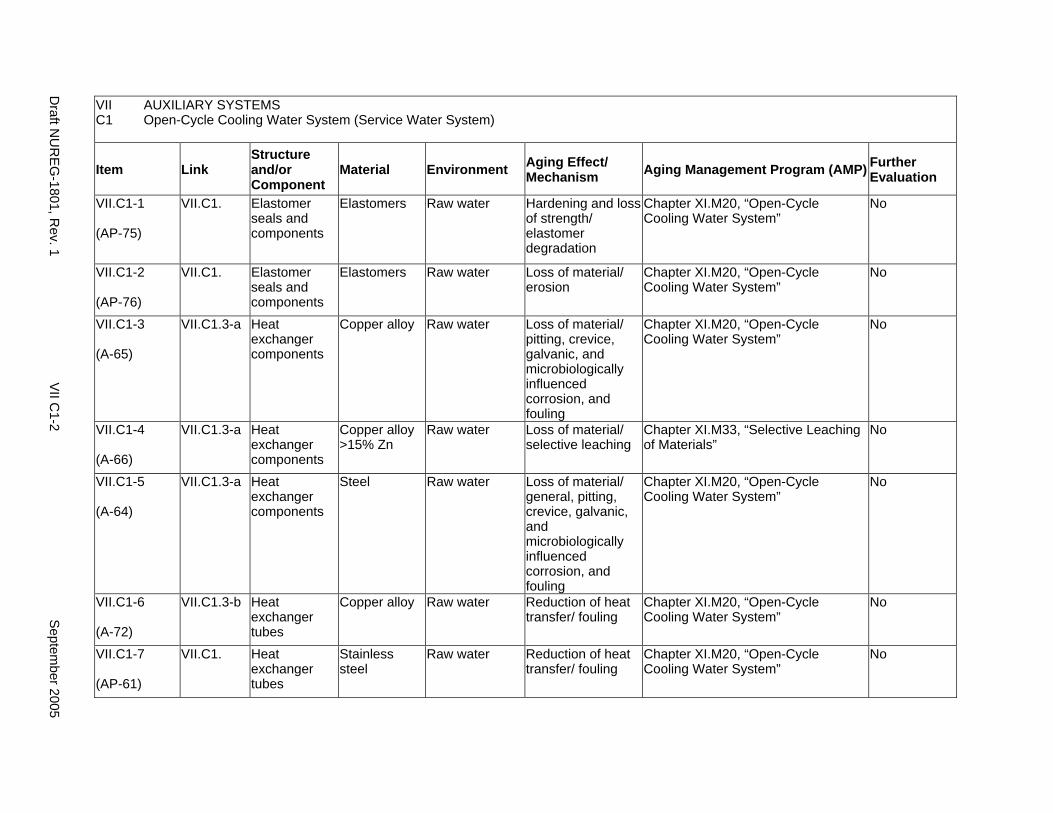
VII AUXILIARY SYSTEMS C1 Open-Cycle Cooling Water System (Service Water System)
Item Link Structure and/or Component
Material Environment Aging Effect/ Mechanism Aging Management Program (AMP) Further
Evaluation
VII.C1-1
(AP-75)
VII.C1. Elastomer seals and components
Elastomers Raw water Hardening and loss of strength/ elastomer degradation
Chapter XI.M20, “Open-Cycle Cooling Water System”
No
VII.C1-2
(AP-76)
VII.C1. Elastomer seals and components
Elastomers Raw water Loss of material/ erosion
Chapter XI.M20, “Open-Cycle Cooling Water System”
No
VII.C1-3
(A-65)
VII.C1.3-a Heat exchanger components
Copper alloy Raw water Loss of material/ pitting, crevice, galvanic, and microbiologically influenced corrosion, and fouling
Chapter XI.M20, “Open-Cycle Cooling Water System”
No
VII.C1-4
(A-66)
VII.C1.3-a Heat exchanger components
Copper alloy >15% Zn
Raw water Loss of material/ selective leaching
Chapter XI.M33, “Selective Leaching of Materials”
No
VII.C1-5
(A-64)
VII.C1.3-a Heat exchanger components
Steel Raw water Loss of material/ general, pitting, crevice, galvanic, and microbiologically influenced corrosion, and fouling
Chapter XI.M20, “Open-Cycle Cooling Water System”
No
VII.C1-6
(A-72)
VII.C1.3-b Heat exchanger tubes
Copper alloy Raw water Reduction of heat transfer/ fouling
Chapter XI.M20, “Open-Cycle Cooling Water System”
No
VII.C1-7
(AP-61)
VII.C1. Heat exchanger tubes
Stainless steel
Raw water Reduction of heat transfer/ fouling
Chapter XI.M20, “Open-Cycle Cooling Water System”
No
Draft N
UR
EG
-1801, Rev. 1
VII C
1-2 S
eptember 2005
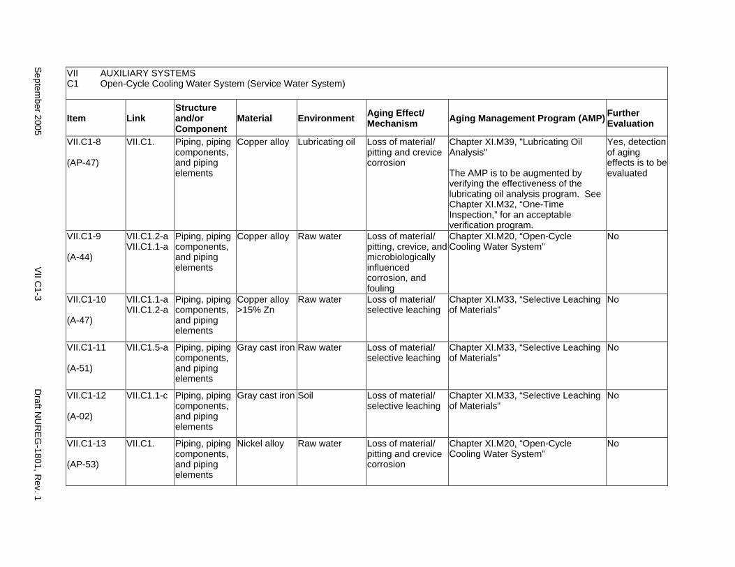
VII AUXILIARY SYSTEMS C1 Open-Cycle Cooling Water System (Service Water System)
Item Link Structure and/or Component
Material Environment Aging Effect/ Mechanism Aging Management Program (AMP) Further
Evaluation
VII.C1-8
(AP-47)
VII.C1. Piping, piping components, and piping elements
Copper alloy Lubricating oil Loss of material/ pitting and crevice corrosion
Chapter XI.M39, "Lubricating Oil Analysis"
The AMP is to be augmented by verifying the effectiveness of the lubricating oil analysis program. See Chapter XI.M32, “One-Time Inspection,” for an acceptable verification program.
Yes, detection of aging effects is to be evaluated
VII.C1-9
(A-44)
VII.C1.2-a VII.C1.1-a
Piping, piping components, and piping elements
Copper alloy Raw water Loss of material/ pitting, crevice, and microbiologically influenced corrosion, and fouling
Chapter XI.M20, “Open-Cycle Cooling Water System”
No
VII.C1-10
(A-47)
VII.C1.1-a VII.C1.2-a
Piping, piping components, and piping elements
Copper alloy >15% Zn
Raw water Loss of material/ selective leaching
Chapter XI.M33, “Selective Leaching of Materials”
No
VII.C1-11
(A-51)
VII.C1.5-a Piping, piping components, and piping elements
Gray cast iron Raw water Loss of material/ selective leaching
Chapter XI.M33, “Selective Leaching of Materials”
No
VII.C1-12
(A-02)
VII.C1.1-c Piping, piping components, and piping elements
Gray cast iron Soil Loss of material/ selective leaching
Chapter XI.M33, “Selective Leaching of Materials"
No
VII.C1-13
(AP-53)
VII.C1. Piping, piping components, and piping elements
Nickel alloy Raw water Loss of material/ pitting and crevice corrosion
Chapter XI.M20, “Open-Cycle Cooling Water System”
No
Septem
ber 2005 V
II C1-3
Draft N
UR
EG
-1801, Rev. 1
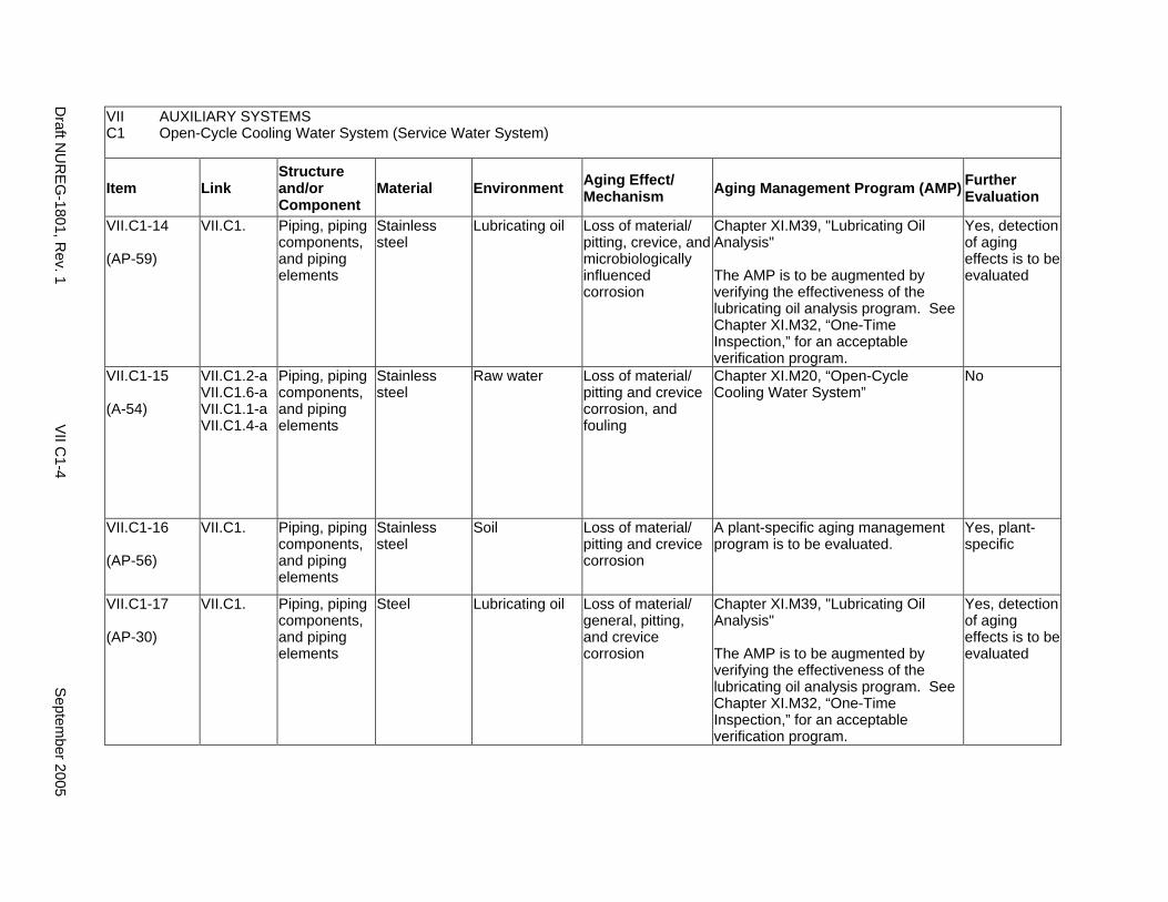
VII AUXILIARY SYSTEMS C1 Open-Cycle Cooling Water System (Service Water System)
Item Link Structure and/or Component
Material Environment Aging Effect/ Mechanism Aging Management Program (AMP) Further
Evaluation
VII.C1-14
(AP-59)
VII.C1. Piping, piping components, and piping elements
Stainless steel
Lubricating oil Loss of material/ pitting, crevice, and microbiologically influenced corrosion
Chapter XI.M39, "Lubricating Oil Analysis"
The AMP is to be augmented by verifying the effectiveness of the lubricating oil analysis program. See Chapter XI.M32, “One-Time Inspection,” for an acceptable verification program.
Yes, detection of aging effects is to be evaluated
VII.C1-15
(A-54)
VII.C1.2-a VII.C1.6-a VII.C1.1-a VII.C1.4-a
Piping, piping components, and piping elements
Stainless steel
Raw water Loss of material/ pitting and crevice corrosion, and fouling
Chapter XI.M20, “Open-Cycle Cooling Water System”
No
VII.C1-16
(AP-56)
VII.C1. Piping, piping components, and piping elements
Stainless steel
Soil Loss of material/ pitting and crevice corrosion
A plant-specific aging management program is to be evaluated.
Yes, plant-specific
VII.C1-17
(AP-30)
VII.C1. Piping, piping components, and piping elements
Steel Lubricating oil Loss of material/ general, pitting, and crevice corrosion
Chapter XI.M39, "Lubricating Oil Analysis"
The AMP is to be augmented by verifying the effectiveness of the lubricating oil analysis program. See Chapter XI.M32, “One-Time Inspection,” for an acceptable verification program.
Yes, detection of aging effects is to be evaluated
Draft N
UR
EG
-1801, Rev. 1
VII C
1-4 S
eptember 2005
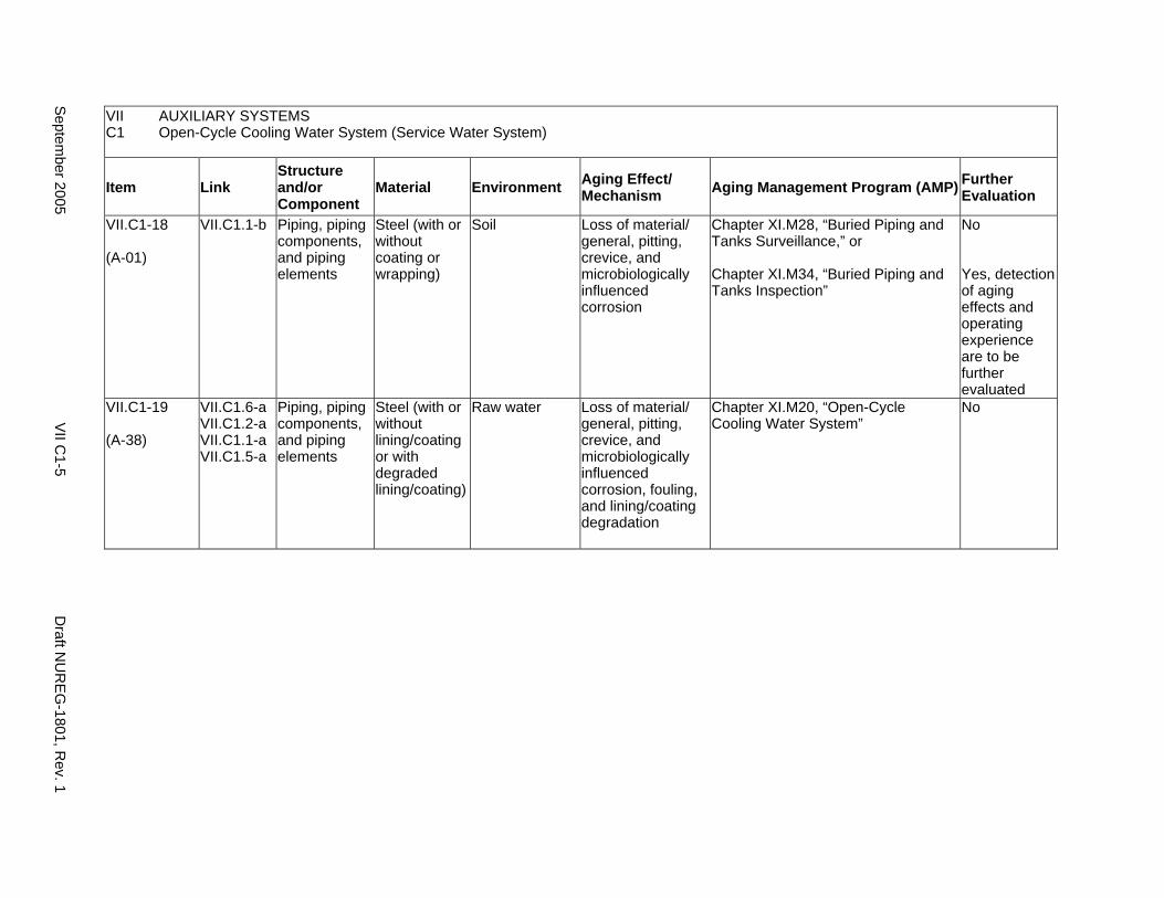
VII AUXILIARY SYSTEMS C1 Open-Cycle Cooling Water System (Service Water System)
Item Link Structure and/or Component
Material Environment Aging Effect/ Mechanism Aging Management Program (AMP) Further
Evaluation
VII.C1-18
(A-01)
VII.C1.1-b Piping, piping components, and piping elements
Steel (with or without coating or wrapping)
Soil Loss of material/ general, pitting, crevice, and microbiologically influenced corrosion
Chapter XI.M28, “Buried Piping and Tanks Surveillance,” or
Chapter XI.M34, “Buried Piping and Tanks Inspection”
No
Yes, detection of aging effects and operating experience are to be further evaluated
VII.C1-19
(A-38)
VII.C1.6-a VII.C1.2-a VII.C1.1-a VII.C1.5-a
Piping, piping components, and piping elements
Steel (with or without lining/coating or with degraded lining/coating)
Raw water Loss of material/ general, pitting, crevice, and microbiologically influenced corrosion, fouling, and lining/coating degradation
Chapter XI.M20, “Open-Cycle Cooling Water System”
No
Septem
ber 2005 V
II C1-5
Draft N
UR
EG
-1801, Rev. 1

This Page Intentionally Left Blank
Draft NUREG-1801, Rev. 1 VII C1-6 September 2005
C2. CLOSED-CYCLE COOLING WATER SYSTEM
Systems, Structures, and Components
This section discusses the closed-cycle cooling water (CCCW) system, which consists of piping, radiation elements, temperature elements, heat exchangers, pumps, tanks, flow orifices, and valves, including containment isolation valves. The system contains chemically treated demineralized water. The closed-cycle cooling water system is designed to remove heat from various auxiliary systems and components such as the chemical and volume control system and the spent fuel cooling system to the open-cycle cooling water system (VII.C1). A CCCW system is defined as part of the service water system that does not reject heat directly to a heat sink, has water chemistry control, and is not subject to significant sources of contamination.
Based on RG 1.26, “Quality Group Classifications and Standards for Water-, Steam-, and Radioactive-Waste-Containing Components of Nuclear Power Plants,” all components in the closed-cycle cooling water system are classified as Group C Quality Standards, with the exception of those forming part of the containment penetration boundary which are Group B.
The aging management programs (AMPs) for the heat exchanger between the closed-cycle and the open-cycle cooling water systems are addressed in the open-cycle cooling water system (VII.C1). The AMPs for the heat exchangers between the closed-cycle cooling water system and the interfacing auxiliary systems are included in the evaluations of their respective systems, such as those for the pressurized water reactor (PWR) and boiling water reactor (BWR) spent fuel pool cooling and cleanup systems (VII.A3 and VII.A4, respectively) and the chemical and volume control system (VII.E1).
Pump and valve internals perform their intended functions with moving parts or with a change in configuration. They are also subject to replacement based on qualified life or specified time period. Pursuant to 10 CFR 54.21(a)(1), therefore, they are not subject to an aging management review.
Aging management programs for the degradation of external surfaces of components and miscellaneous bolting are included in VII.I. Common miscellaneous material/environment combinations where aging effects are not expected to degrade the ability of the structure or component to perform its intended function for the extended period of operation are included in VII.J.
The system piping includes all pipe sizes, including instrument piping.
System Interfaces
The systems that interface with the closed-cycle cooling water system include the open-cycle cooling water system (VII.C1), the PWR spent fuel pool cooling and cleanup system (VII.A3), the BWR spent fuel pool cooling and cleanup system (VII.A4), the chemical and volume control system (VII.E1), the BWR reactor water cleanup system (VII.E3), the shutdown cooling system (older BWR, VII.E4), the primary containment heating and ventilation system (VII.F3), fire protection (VII.G), the emergency diesel generator system (VII.H2), the PWR containment spray system (V.A), the PWR and BWR emergency core cooling systems (V.D1 and V.D2), the PWR steam generator blowdown system (VIII.F), the condensate system (VIII.E), and the PWR auxiliary feedwater system (VIII.G).
September 2005 VII C2-1 Draft NUREG-1801, Rev. 1
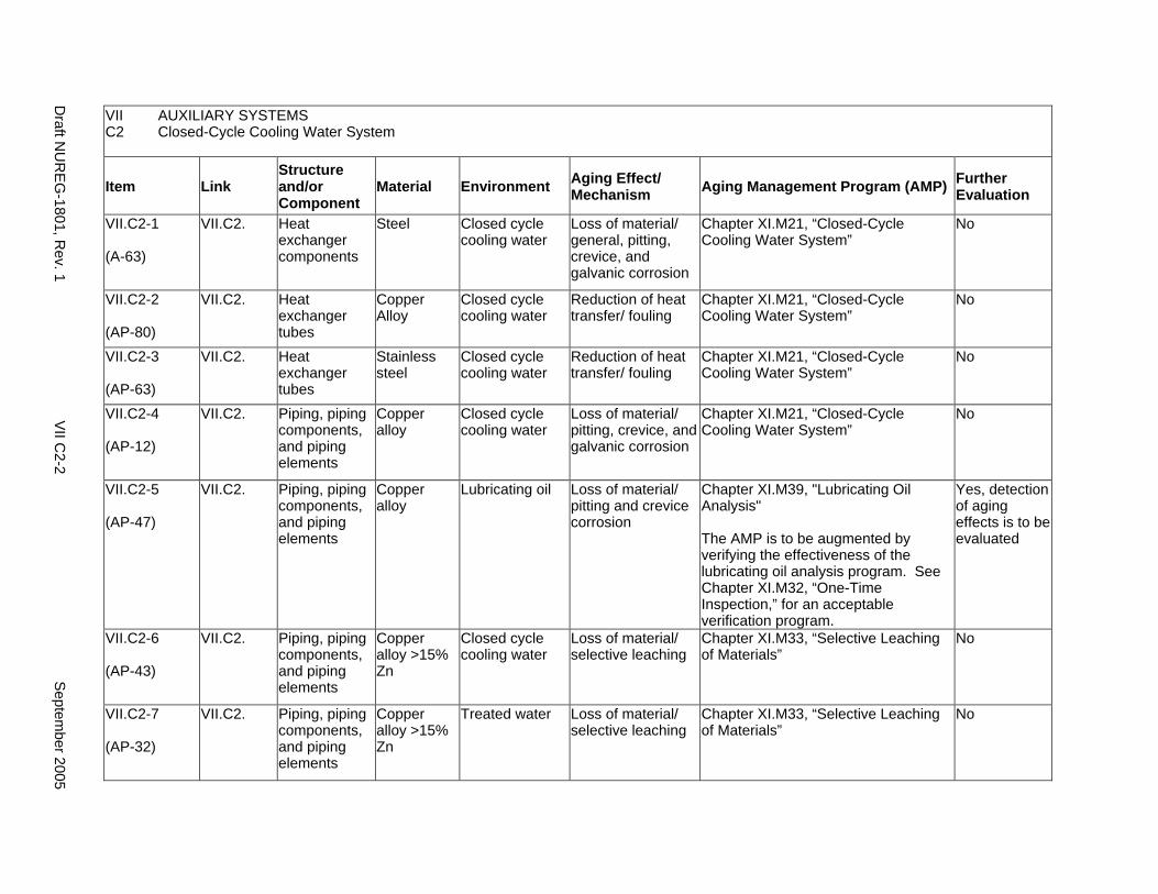
VII AUXILIARY SYSTEMS C2 Closed-Cycle Cooling Water System
Item Link Structure and/or Component
Material Environment Aging Effect/ Mechanism Aging Management Program (AMP) Further
Evaluation
VII.C2-1
(A-63)
VII.C2. Heat exchanger components
Steel Closed cycle cooling water
Loss of material/ general, pitting, crevice, and galvanic corrosion
Chapter XI.M21, “Closed-Cycle Cooling Water System”
No
VII.C2-2
(AP-80)
VII.C2. Heat exchanger tubes
Copper Alloy
Closed cycle cooling water
Reduction of heat transfer/ fouling
Chapter XI.M21, “Closed-Cycle Cooling Water System”
No
VII.C2-3
(AP-63)
VII.C2. Heat exchanger tubes
Stainless steel
Closed cycle cooling water
Reduction of heat transfer/ fouling
Chapter XI.M21, “Closed-Cycle Cooling Water System”
No
VII.C2-4
(AP-12)
VII.C2. Piping, piping components, and piping elements
Copper alloy
Closed cycle cooling water
Loss of material/ pitting, crevice, and galvanic corrosion
Chapter XI.M21, “Closed-Cycle Cooling Water System”
No
VII.C2-5
(AP-47)
VII.C2. Piping, piping components, and piping elements
Copper alloy
Lubricating oil Loss of material/ pitting and crevice corrosion
Chapter XI.M39, "Lubricating Oil Analysis"
The AMP is to be augmented by verifying the effectiveness of the lubricating oil analysis program. See Chapter XI.M32, “One-Time Inspection,” for an acceptable verification program.
Yes, detection of aging effects is to be evaluated
VII.C2-6
(AP-43)
VII.C2. Piping, piping components, and piping elements
Copper alloy >15% Zn
Closed cycle cooling water
Loss of material/ selective leaching
Chapter XI.M33, “Selective Leaching of Materials”
No
VII.C2-7
(AP-32)
VII.C2. Piping, piping components, and piping elements
Copper alloy >15% Zn
Treated water Loss of material/ selective leaching
Chapter XI.M33, “Selective Leaching of Materials”
No
Draft N
UR
EG
-1801, Rev. 1
VII C
2-2 S
eptember 2005
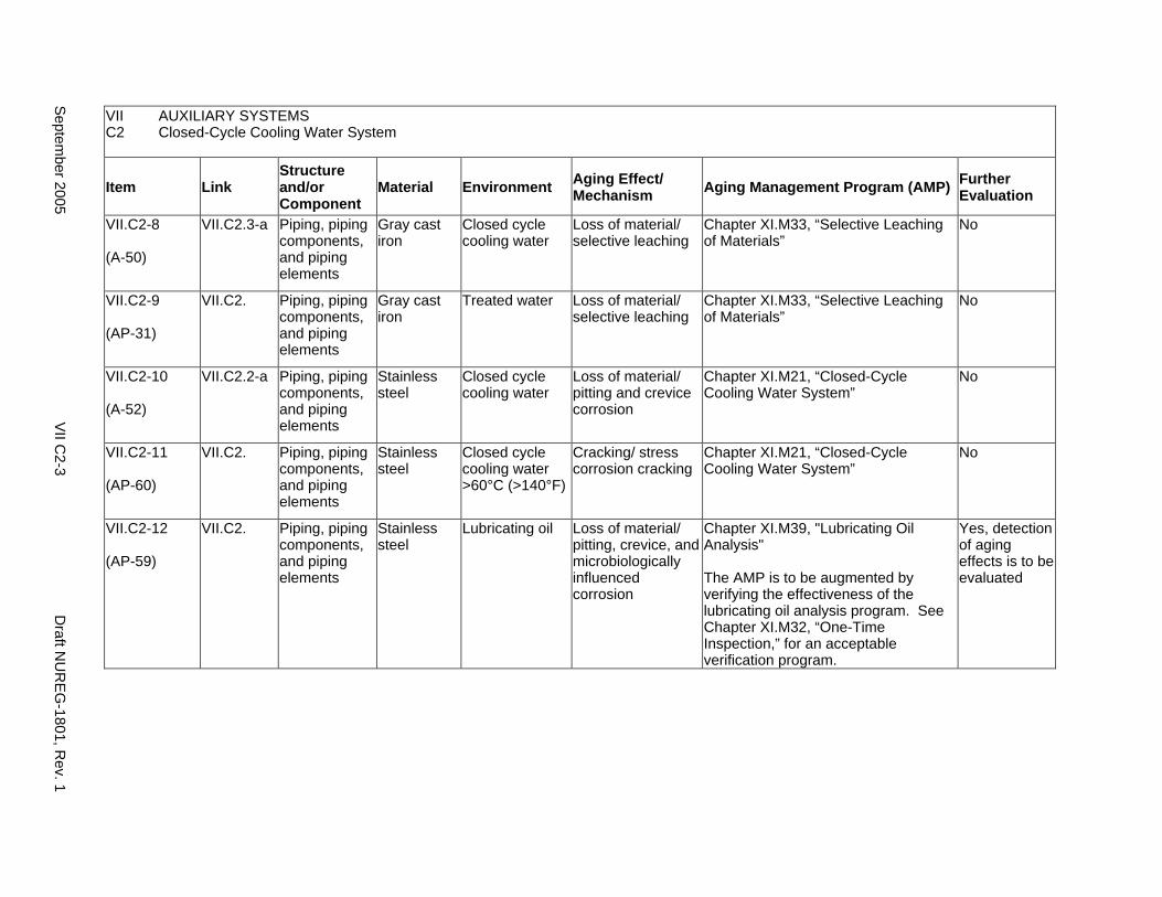
VII AUXILIARY SYSTEMS C2 Closed-Cycle Cooling Water System
Item Link Structure and/or Component
Material Environment Aging Effect/ Mechanism Aging Management Program (AMP) Further
Evaluation
VII.C2-8
(A-50)
VII.C2.3-a Piping, piping components, and piping elements
Gray cast iron
Closed cycle cooling water
Loss of material/ selective leaching
Chapter XI.M33, “Selective Leaching of Materials”
No
VII.C2-9
(AP-31)
VII.C2. Piping, piping components, and piping elements
Gray cast iron
Treated water Loss of material/ selective leaching
Chapter XI.M33, “Selective Leaching of Materials”
No
VII.C2-10
(A-52)
VII.C2.2-a Piping, piping components, and piping elements
Stainless steel
Closed cycle cooling water
Loss of material/ pitting and crevice corrosion
Chapter XI.M21, “Closed-Cycle Cooling Water System”
No
VII.C2-11
(AP-60)
VII.C2. Piping, piping components, and piping elements
Stainless steel
Closed cycle cooling water >60°C (>140°F)
Cracking/ stress corrosion cracking
Chapter XI.M21, “Closed-Cycle Cooling Water System”
No
VII.C2-12
(AP-59)
VII.C2. Piping, piping components, and piping elements
Stainless steel
Lubricating oil Loss of material/ pitting, crevice, and microbiologically influenced corrosion
Chapter XI.M39, "Lubricating Oil Analysis"
The AMP is to be augmented by verifying the effectiveness of the lubricating oil analysis program. See Chapter XI.M32, “One-Time Inspection,” for an acceptable verification program.
Yes, detection of aging effects is to be evaluated
Septem
ber 2005 V
II C2-3
Draft N
UR
EG
-1801, Rev. 1
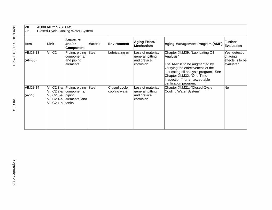
VII AUXILIARY SYSTEMS C2 Closed-Cycle Cooling Water System
Item Link Structure and/or Component
Material Environment Aging Effect/ Mechanism Aging Management Program (AMP) Further
Evaluation
VII.C2-13
(AP-30)
VII.C2. Piping, piping components, and piping elements
Steel Lubricating oil Loss of material/ general, pitting, and crevice corrosion
Chapter XI.M39, "Lubricating Oil Analysis"
The AMP is to be augmented by verifying the effectiveness of the lubricating oil analysis program. See Chapter XI.M32, “One-Time Inspection,” for an acceptable verification program.
Yes, detection of aging effects is to be evaluated
VII.C2-14
(A-25)
VII.C2.3-a VII.C2.2-a VII.C2.5-a VII.C2.4-a VII.C2.1-a
Piping, piping components, piping elements, and tanks
Steel Closed cycle cooling water
Loss of material/ general, pitting, and crevice corrosion
Chapter XI.M21, “Closed-Cycle Cooling Water System”
No
Draft N
UR
EG
-1801, Rev. 1
VII C
2-4 S
eptember 2005
C3. ULTIMATE HEAT SINK
Systems, Structures, and Components
The ultimate heat sink (UHS) consists of a lake, ocean, river, spray pond, or cooling tower. The UHS provides sufficient cooling water for safe reactor shutdown and reactor cooldown via the residual heat removal system or other similar system. Due to the varying configurations of connections to lakes, oceans, and rivers, a plant specific aging management program (AMP) is required. Appropriate AMPs shall be provided to trend and project (1) deterioration of earthen dams and impoundments; (2) rate of silt deposition; (3) meteorological, climatological, and oceanic data since obtaining the Final Safety Analysis Report (FSAR) data; (4) water level extremes for plants located on rivers; and (5) aging degradation of all upstream and downstream dams affecting the UHS.
The systems, structures, and components included in this section consist of piping, valves, and pumps. The cooling tower is addressed in this report on water-control structures (III.A6). The ultimate heat sink absorbs heat from the residual heat removal system or other similar system. Based on Regulatory Guide 1.26, “Quality Group Classifications and Standards for Water-, Steam-, and Radioactive-Waste-Containing Components of Nuclear Power Plants,” the piping and valves used for the ultimate heat sink are governed by Group C Quality Standards.
Pump and valve internals perform their intended functions with moving parts or with a change in configuration. They are also subject to replacement based on qualified life or specified time period. Pursuant to 10 CFR 54.21(a)(1), therefore, they are not subject to an aging management review.
Aging management programs for the degradation of external surfaces of components and miscellaneous bolting are included in VII.I. Common miscellaneous material/environment combinations where aging effects are not expected to degrade the ability of the structure or component to perform its intended function for the extended period of operation are included in VII.J.
The system piping includes all pipe sizes, including instrument piping.
System Interfaces
The systems that interface with the ultimate heat sink include the open-cycle cooling water system (VII.C1) and the PWR and BWR emergency core cooling systems (V.D1 and V.D2).
September 2005 VII C3-1 Draft NUREG-1801, Rev. 1

VII AUXILIARY SYSTEMS C3 Ultimate Heat Sink
Item Link Structure and/or Component
Material Environment Aging Effect/ Mechanism Aging Management Program (AMP) Further
Evaluation
VII.C3-1
(AP-61)
VII.C3. Heat exchanger tubes
Stainless steel
Raw water Reduction of heat transfer/ fouling
Chapter XI.M20, “Open-Cycle Cooling Water System”
No
VII.C3-2
(A-43)
VII.C3.1-a VII.C3.2-a
Piping, piping components, and piping elements
Copper alloy Raw water Loss of material/ pitting and crevice corrosion
Chapter XI.M20, “Open-Cycle Cooling Water System”
No
VII.C3-3
(A-47)
VII.C3.2-a VII.C3.1-a
Piping, piping components, and piping elements
Copper alloy >15% Zn
Raw water Loss of material/ selective leaching
Chapter XI.M33, “Selective Leaching of Materials”
No
VII.C3-4
(A-51)
VII.C3. Piping, piping components, and piping elements
Gray cast iron Raw water Loss of material/ selective leaching
Chapter XI.M33, “Selective Leaching of Materials”
No
VII.C3-5
(A-02)
VII.C3. Piping, piping components, and piping elements
Gray cast iron Soil Loss of material/ selective leaching
Chapter XI.M33, “Selective Leaching of Materials"
No
VII.C3-6
(AP-53)
VII.C3. Piping, piping components, and piping elements
Nickel alloy Raw water Loss of material/ pitting and crevice corrosion
Chapter XI.M20, “Open-Cycle Cooling Water System”
No
VII.C3-7
(A-53)
VII.C3.2-a Piping, piping components, and piping elements
Stainless steel
Raw water Loss of material/ pitting and crevice corrosion
Chapter XI.M20, “Open-Cycle Cooling Water System”
No
Draft N
UR
EG
-1801, Rev. 1
VII C
3-2 S
eptember 2005
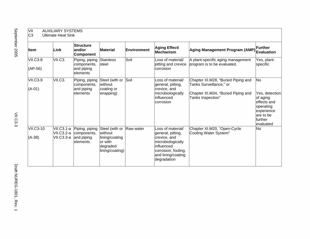
VII AUXILIARY SYSTEMS C3 Ultimate Heat Sink
Item Link Structure and/or Component
Material Environment Aging Effect/ Mechanism Aging Management Program (AMP) Further
Evaluation
VII.C3-8
(AP-56)
VII.C3. Piping, piping components, and piping elements
Stainless steel
Soil Loss of material/ pitting and crevice corrosion
A plant-specific aging management program is to be evaluated.
Yes, plant-specific
VII.C3-9
(A-01)
VII.C3. Piping, piping components, and piping elements
Steel (with or without coating or wrapping)
Soil Loss of material/ general, pitting, crevice, and microbiologically influenced corrosion
Chapter XI.M28, “Buried Piping and Tanks Surveillance,” or
Chapter XI.M34, “Buried Piping and Tanks Inspection”
No
Yes, detection of aging effects and operating experience are to be further evaluated
VII.C3-10
(A-38)
VII.C3.1-a VII.C3.2-a VII.C3.3-a
Piping, piping components, and piping elements
Steel (with or without lining/coating or with degraded lining/coating)
Raw water Loss of material/ general, pitting, crevice, and microbiologically influenced corrosion, fouling, and lining/coating degradation
Chapter XI.M20, “Open-Cycle Cooling Water System”
No
Septem
ber 2005 V
II C3-3
Draft N
UR
EG
-1801, Rev. 1

This Page Intentionally Left Blank
Draft NUREG-1801, Rev. 1 VII C3-4 September 2005
D. COMPRESSED AIR SYSTEM
Systems, Structures, and Components
This section discusses the compressed air system, which consists of piping, valves (including containment isolation valves), air receiver, pressure regulators, filters, and dryers. The system components and piping are located in various buildings at most nuclear power plants. Based on Regulatory Guide 1.26, “Quality Group Classifications and Standards for Water-, Steam-, and Radioactive-Waste-Containing Components of Nuclear Power Plants,” all components of the compressed air system are classified as Group D Quality Standards, with the exception of those forming part of the containment penetration boundary which are Group B. However, the cleanliness of these components and high air quality is to be maintained because the air provides the motive power for instruments and active components (some of them safety-related) that may not function properly if nonsafety Group D equipment is contaminated.
With respect to filters, these items are to be addressed consistent with the Nuclear Regulatory Commission (NRC) position on consumables, provided in the NRC letter from Christopher I. Grimes to Douglas J. Walters of Nuclear Energy Institute (NEI), dated March 10, 2000. Specifically, components that function as system filters are typically replaced based on performance or condition monitoring that identifies whether these components are at the end of their qualified lives and may be excluded, on a plant-specific basis, from an aging management review under 10 CFR 54.21(a)(1)(ii). As part of the methodology description, the application should identify the standards that are relied on for replacement, for example, National Fire Protection Association (NFPA) standards for fire protection equipment.
Pump and valve internals perform their intended functions with moving parts or with a change in configuration. They are also subject to replacement based on qualified life or specified time period. Pursuant to 10 CFR 54.21(a)(1), therefore, they are not subject to an aging management review.
Aging management programs for the degradation of external surfaces of components and miscellaneous bolting are included in VII.I. Common miscellaneous material/environment combinations where aging effects are not expected to degrade the ability of the structure or component to perform its intended function for the extended period of operation are included in VII.J.
The system piping includes all pipe sizes, including instrument piping.
System Interfaces
Various other systems discussed in this report may interface with the compressed air system.
September 2005 VII D-1 Draft NUREG-1801, Rev. 1
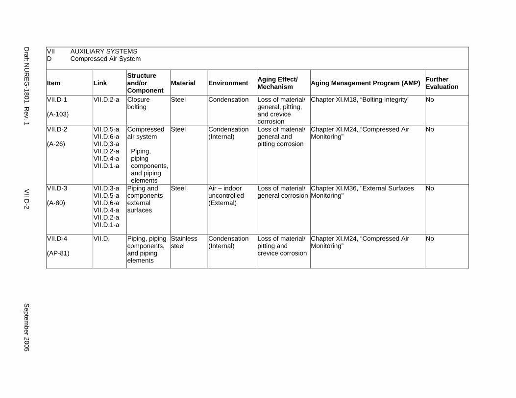
VII AUXILIARY SYSTEMS D Compressed Air System
Item Link Structure and/or Component
Material Environment Aging Effect/ Mechanism Aging Management Program (AMP) Further
Evaluation
VII.D-1
(A-103)
VII.D.2-a Closure bolting
Steel Condensation Loss of material/ general, pitting, and crevice corrosion
Chapter XI.M18, “Bolting Integrity” No
VII.D-2
(A-26)
VII.D.5-a VII.D.6-a VII.D.3-a VII.D.2-a VII.D.4-a VII.D.1-a
Compressed air system
Piping, piping components, and piping elements
Steel Condensation (Internal)
Loss of material/ general and pitting corrosion
Chapter XI.M24, “Compressed Air Monitoring”
No
VII.D-3
(A-80)
VII.D.3-a VII.D.5-a VII.D.6-a VII.D.4-a VII.D.2-a VII.D.1-a
Piping and components external surfaces
Steel Air – indoor uncontrolled (External)
Loss of material/ general corrosion
Chapter XI.M36, "External Surfaces Monitoring"
No
VII.D-4
(AP-81)
VII.D. Piping, piping components, and piping elements
Stainless steel
Condensation (Internal)
Loss of material/ pitting and crevice corrosion
Chapter XI.M24, “Compressed Air Monitoring”
No
Draft N
UR
EG
-1801, Rev. 1
VII D
-2 S
eptember 2005

E1. CHEMICAL AND VOLUME CONTROL SYSTEM (PRESSURIZED WATER REACTOR)
Systems, Structures, and Components
This section discusses a portion of the pressurized water reactor (PWR) chemical and volume control system (CVCS). The portion of the PWR CVCS covered in this section extends from the isolation valves associated with the reactor coolant pressure boundary (and Code change as discussed below) to the volume control tank. This portion of the PWR CVCS consists of high-and low-pressure piping and valves (including the containment isolation valves), regenerative and letdown heat exchangers, pumps, basket strainers, and the volume control tank. The system contains chemically treated borated water; the shell side of the letdown heat exchanger contains closed-cycle cooling water (treated water).
Based on Regulatory Guide 1.26, “Quality Group Classifications and Standards for Water-, Steam-, and Radioactive-Waste-Containing Components of Nuclear Power Plants,” all components that comprise the CVCS are governed by Group C Quality Standards. Portions of the CVCS extending from the reactor coolant system up to and including the isolation valves associated with reactor coolant pressure boundary are governed by Group A Quality Standards and covered in IV.C2.
Pump and valve internals perform their intended functions with moving parts or with a change in configuration. They are also subject to replacement based on qualified life or specified time period. Pursuant to 10 CFR 54.21(a)(1), therefore, they are not subject to an aging management review.
Aging management programs for the degradation of external surfaces of components and miscellaneous bolting are included in VII.I. Common miscellaneous material/environment combinations where aging effects are not expected to degrade the ability of the structure or component to perform its intended function for the extended period of operation are included in VII.J.
The system piping includes all pipe sizes, including instrument piping.
System Interfaces
The systems that interface with the chemical and volume control system include the reactor coolant system (IV.C2), the emergency core cooling system (V.D1), the spent fuel pool cooling system (VII.A3), and the closed-cycle cooling water system (VII.C2).
September 2005 VII E1-1 Draft NUREG-1801, Rev. 1
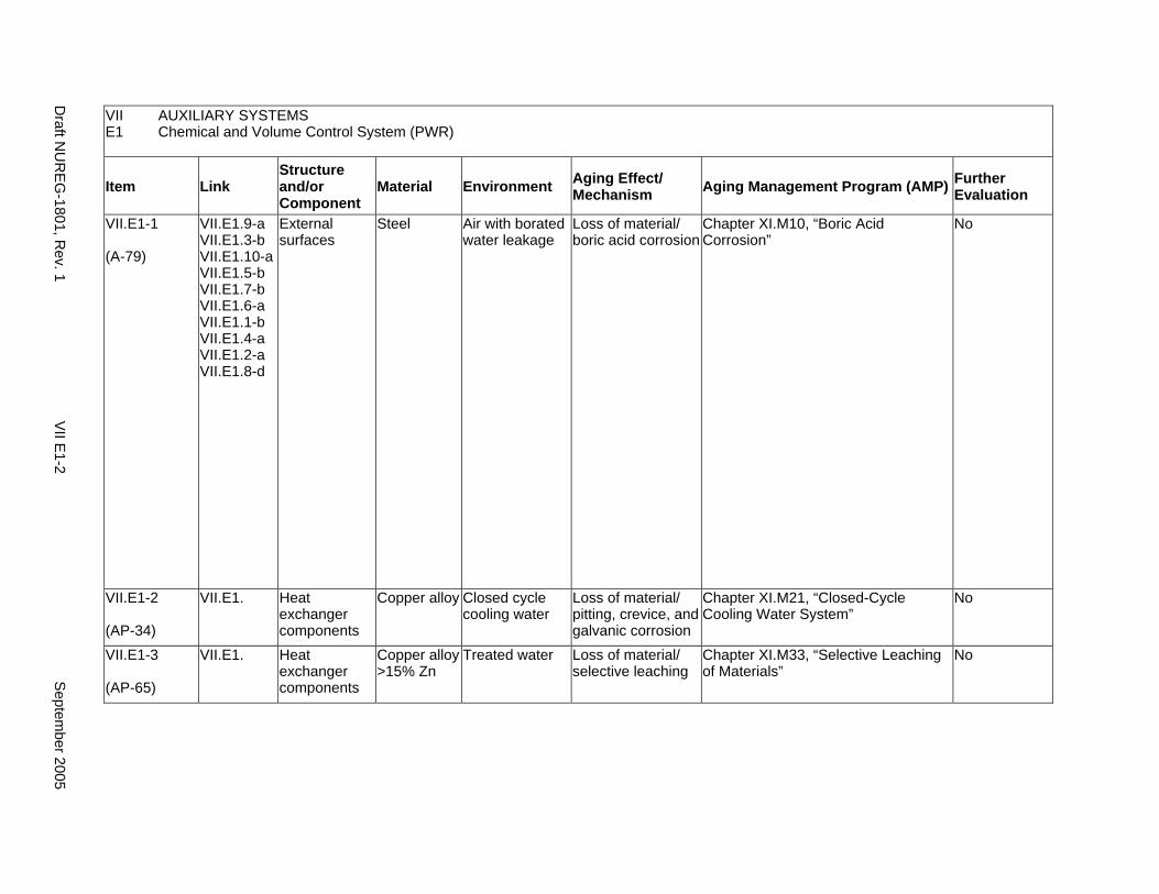
VII AUXILIARY SYSTEMS E1 Chemical and Volume Control System (PWR)
Item Link Structure and/or Component
Material Environment Aging Effect/ Mechanism Aging Management Program (AMP) Further
Evaluation
VII.E1-1
(A-79)
VII.E1.9-a VII.E1.3-b VII.E1.10-a VII.E1.5-b VII.E1.7-b VII.E1.6-a VII.E1.1-b VII.E1.4-a VII.E1.2-a VII.E1.8-d
External surfaces
Steel Air with borated water leakage
Loss of material/ boric acid corrosion
Chapter XI.M10, “Boric Acid Corrosion”
No
VII.E1-2
(AP-34)
VII.E1. Heat exchanger components
Copper alloy Closed cycle cooling water
Loss of material/ pitting, crevice, and galvanic corrosion
Chapter XI.M21, “Closed-Cycle Cooling Water System”
No
VII.E1-3
(AP-65)
VII.E1. Heat exchanger components
Copper alloy >15% Zn
Treated water Loss of material/ selective leaching
Chapter XI.M33, “Selective Leaching of Materials”
No
Draft N
UR
EG
-1801, Rev. 1
VII E
1-2 S
eptember 2005
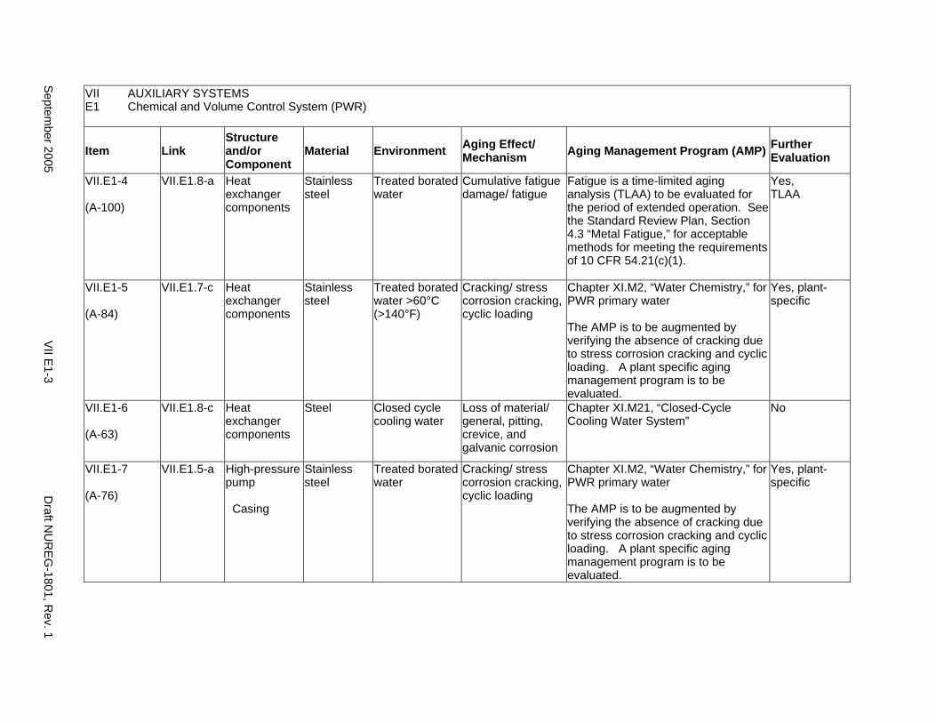
VII AUXILIARY SYSTEMS E1 Chemical and Volume Control System (PWR)
Item Link Structure and/or Component
Material Environment Aging Effect/ Mechanism Aging Management Program (AMP) Further
Evaluation
VII.E1-4
(A-100)
VII.E1.8-a Heat exchanger components
Stainless steel
Treated borated water
Cumulative fatigue damage/ fatigue
Fatigue is a time-limited aging analysis (TLAA) to be evaluated for the period of extended operation. See the Standard Review Plan, Section 4.3 “Metal Fatigue,” for acceptable methods for meeting the requirements of 10 CFR 54.21(c)(1).
Yes, TLAA
VII.E1-5
(A-84)
VII.E1.7-c Heat exchanger components
Stainless steel
Treated borated water >60°C (>140°F)
Cracking/ stress corrosion cracking, cyclic loading
Chapter XI.M2, “Water Chemistry,” for PWR primary water
The AMP is to be augmented by verifying the absence of cracking due to stress corrosion cracking and cyclic loading. A plant specific aging management program is to be evaluated.
Yes, plant-specific
VII.E1-6
(A-63)
VII.E1.8-c Heat exchanger components
Steel Closed cycle cooling water
Loss of material/ general, pitting, crevice, and galvanic corrosion
Chapter XI.M21, “Closed-Cycle Cooling Water System”
No
VII.E1-7
(A-76)
VII.E1.5-a High-pressure pump
Casing
Stainless steel
Treated borated water
Cracking/ stress corrosion cracking, cyclic loading
Chapter XI.M2, “Water Chemistry,” for PWR primary water
The AMP is to be augmented by verifying the absence of cracking due to stress corrosion cracking and cyclic loading. A plant specific aging management program is to be evaluated.
Yes, plant-specific
Septem
ber 2005 V
II E1-3
Draft N
UR
EG
-1801, Rev. 1
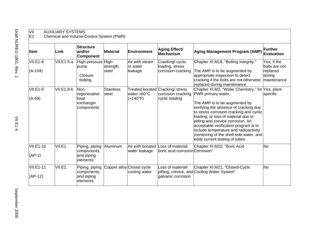
VII AUXILIARY SYSTEMS E1 Chemical and Volume Control System (PWR)
Item Link Structure and/or Component
Material Environment Aging Effect/ Mechanism Aging Management Program (AMP) Further
Evaluation
VII.E1-8
(A-104)
VII.E1.5-a High-pressure pump
Closure bolting
High-strength steel
Air with steam or water leakage
Cracking/ cyclic loading, stress corrosion cracking
Chapter XI.M18, “Bolting Integrity.”
The AMP is to be augmented by appropriate inspection to detect cracking if the bolts are not otherwise replaced during maintenance.
Yes, if the bolts are not replaced during maintenance
VII.E1-9
(A-69)
VII.E1.8-b Non-regenerative heat exchanger components
Stainless steel
Treated borated water >60°C (>140°F)
Cracking/ stress corrosion cracking, cyclic loading
Chapter XI.M2, “Water Chemistry,” for PWR primary water.
The AMP is to be augmented by verifying the absence of cracking due to stress corrosion cracking and cyclic loading, or loss of material due to pitting and crevice corrosion. An acceptable verification program is to include temperature and radioactivity monitoring of the shell side water, and eddy current testing of tubes.
Yes, plant-specific
VII.E1-10
(AP-1)
VII.E1. Piping, piping components, and piping elements
Aluminum Air with borated water leakage
Loss of material/ boric acid corrosion
Chapter XI.M10, “Boric Acid Corrosion”
No
VII.E1-11
(AP-12)
VII.E1. Piping, piping components, and piping elements
Copper alloy Closed cycle cooling water
Loss of material/ pitting, crevice, and galvanic corrosion
Chapter XI.M21, “Closed-Cycle Cooling Water System”
No
Draft N
UR
EG
-1801, Rev. 1
VII E
1-4 S
eptember 2005
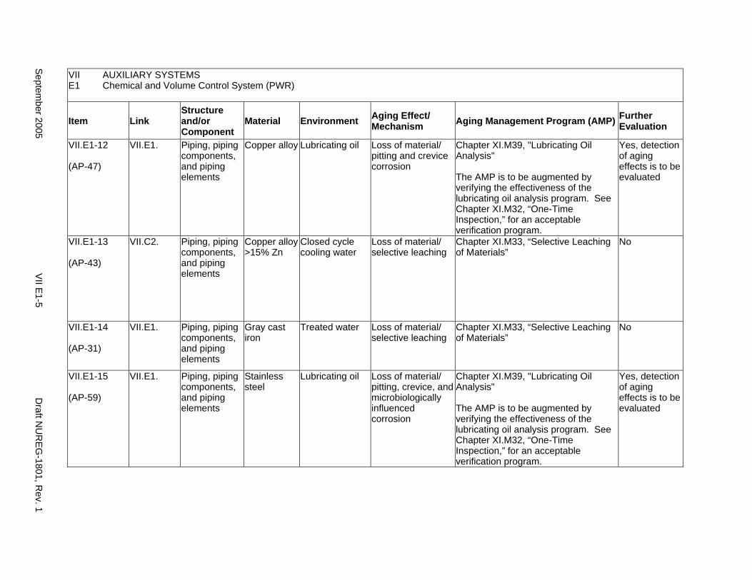
VII AUXILIARY SYSTEMS E1 Chemical and Volume Control System (PWR)
Item Link Structure and/or Component
Material Environment Aging Effect/ Mechanism Aging Management Program (AMP) Further
Evaluation
VII.E1-12
(AP-47)
VII.E1. Piping, piping components, and piping elements
Copper alloy Lubricating oil Loss of material/ pitting and crevice corrosion
Chapter XI.M39, "Lubricating Oil Analysis"
The AMP is to be augmented by verifying the effectiveness of the lubricating oil analysis program. See Chapter XI.M32, “One-Time Inspection,” for an acceptable verification program.
Yes, detection of aging effects is to be evaluated
VII.E1-13
(AP-43)
VII.C2. Piping, piping components, and piping elements
Copper alloy >15% Zn
Closed cycle cooling water
Loss of material/ selective leaching
Chapter XI.M33, “Selective Leaching of Materials”
No
VII.E1-14
(AP-31)
VII.E1. Piping, piping components, and piping elements
Gray cast iron
Treated water Loss of material/ selective leaching
Chapter XI.M33, “Selective Leaching of Materials”
No
VII.E1-15
(AP-59)
VII.E1. Piping, piping components, and piping elements
Stainless steel
Lubricating oil Loss of material/ pitting, crevice, and microbiologically influenced corrosion
Chapter XI.M39, "Lubricating Oil Analysis"
The AMP is to be augmented by verifying the effectiveness of the lubricating oil analysis program. See Chapter XI.M32, “One-Time Inspection,” for an acceptable verification program.
Yes, detection of aging effects is to be evaluated
Septem
ber 2005 V
II E1-5
Draft N
UR
EG
-1801, Rev. 1
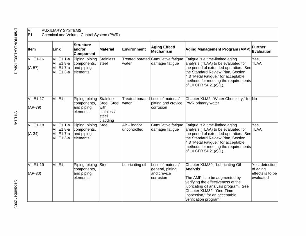
VII AUXILIARY SYSTEMS E1 Chemical and Volume Control System (PWR)
Item Link Structure and/or Component
Material Environment Aging Effect/ Mechanism Aging Management Program (AMP) Further
Evaluation
VII.E1-16
(A-57)
VII.E1.1-a VII.E1.8-a VII.E1.7-a VII.E1.3-a
Piping, piping components, and piping elements
Stainless steel
Treated borated water
Cumulative fatigue damage/ fatigue
Fatigue is a time-limited aging analysis (TLAA) to be evaluated for the period of extended operation. See the Standard Review Plan, Section 4.3 “Metal Fatigue,” for acceptable methods for meeting the requirements of 10 CFR 54.21(c)(1).
Yes, TLAA
VII.E1-17
(AP-79)
VII.E1. Piping, piping components, and piping elements
Stainless Steel; Steel with stainless steel cladding
Treated borated water
Loss of material/ pitting and crevice corrosion
Chapter XI.M2, “Water Chemistry,” for PWR primary water
No
VII.E1-18
(A-34)
VII.E1.1-a VII.E1.8-a VII.E1.7-a VII.E1.3-a
Piping, piping components, and piping elements
Steel Air – indoor uncontrolled
Cumulative fatigue damage/ fatigue
Fatigue is a time-limited aging analysis (TLAA) to be evaluated for the period of extended operation. See the Standard Review Plan, Section 4.3 “Metal Fatigue,” for acceptable methods for meeting the requirements of 10 CFR 54.21(c)(1).
Yes, TLAA
VII.E1-19
(AP-30)
VII.E1. Piping, piping components, and piping elements
Steel Lubricating oil Loss of material/ general, pitting, and crevice corrosion
Chapter XI.M39, "Lubricating Oil Analysis"
The AMP is to be augmented by verifying the effectiveness of the lubricating oil analysis program. See Chapter XI.M32, “One-Time Inspection,” for an acceptable verification program.
Yes, detection of aging effects is to be evaluated
Draft N
UR
EG
-1801, Rev. 1
VII E
1-6 S
eptember 2005
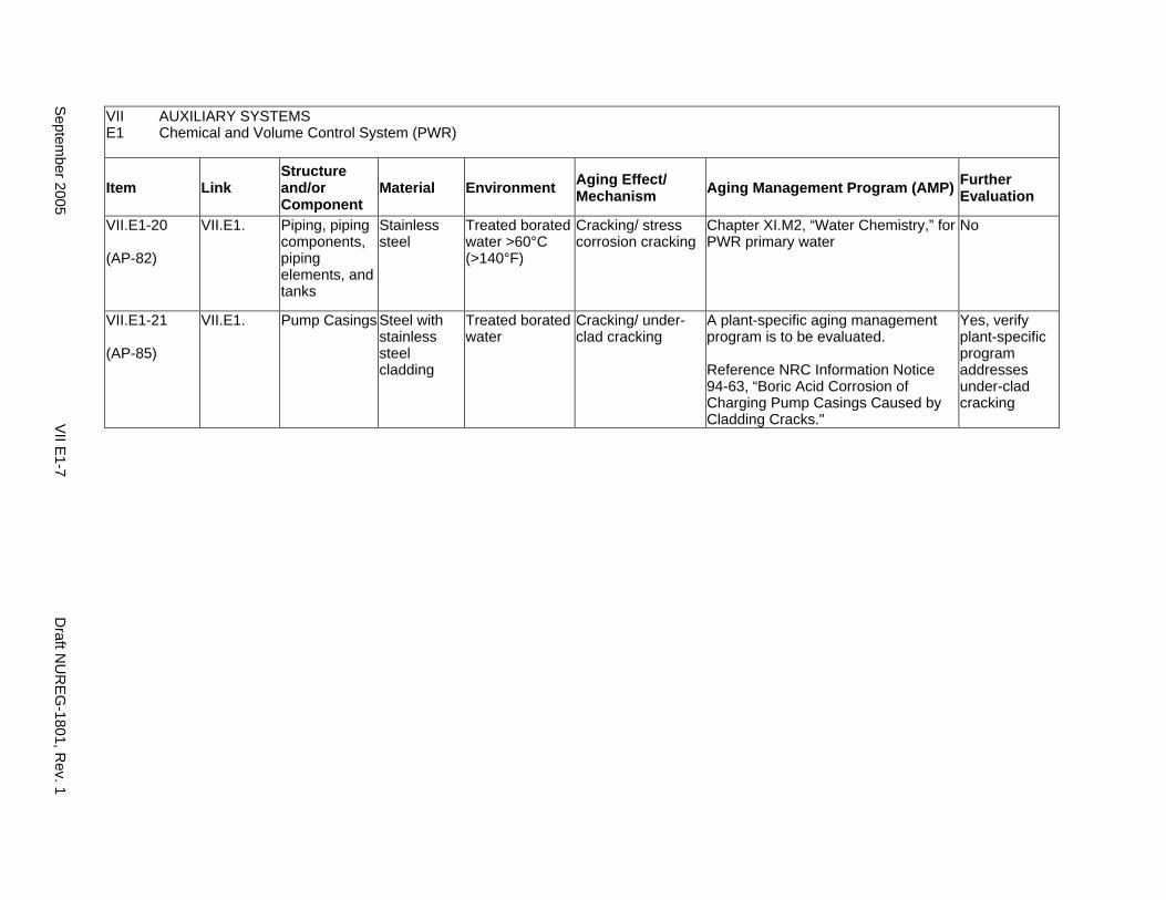
VII AUXILIARY SYSTEMS E1 Chemical and Volume Control System (PWR)
Item Link Structure and/or Component
Material Environment Aging Effect/ Mechanism Aging Management Program (AMP) Further
Evaluation
VII.E1-20
(AP-82)
VII.E1. Piping, piping components, piping elements, and tanks
Stainless steel
Treated borated water >60°C (>140°F)
Cracking/ stress corrosion cracking
Chapter XI.M2, “Water Chemistry,” for PWR primary water
No
VII.E1-21
(AP-85)
VII.E1. Pump Casings Steel with stainless steel cladding
Treated borated water
Cracking/ under-clad cracking
A plant-specific aging management program is to be evaluated.
Reference NRC Information Notice 94-63, “Boric Acid Corrosion of Charging Pump Casings Caused by Cladding Cracks."
Yes, verify plant-specific program addresses under-clad cracking
Septem
ber 2005 V
II E1-7
Draft N
UR
EG
-1801, Rev. 1

This Page Intentionally Left Blank
Draft NUREG-1801, Rev. 1 VII E1-8 September 2005
E2. STANDBY LIQUID CONTROL SYSTEM (BOILING WATER REACTOR)
Systems, Structures, and Components
This section discusses the portion of the standby liquid control (SLC) system extending from the containment isolation valve to the solution storage tank. The system serves as a backup reactivity control system in all boiling water reactors (BWRs). The major components of this system are the piping, the solution storage tank, the solution storage tank heaters, valves, and pumps. All of the components from the storage tank to the explosive actuated discharge valve operate in contact with a sodium pentaborate (Na2B10O16•10H2O) solution.
Based on Regulatory Guide 1.26, “Quality Group Classifications and Standards for Water-, Steam-, and Radioactive-Waste-Containing Components of Nuclear Power Plants,” all components that comprise the standby liquid control system are governed by Group B Quality Standards. The portions of the standby liquid control system extending from the reactor coolant pressure boundary up to and including the containment isolation valves are governed by Group A Quality Standards and are covered in IV.C1.
Pump and valve internals perform their intended functions with moving parts or with a change in configuration. They are also subject to replacement based on qualified life or specified time period. Pursuant to 10 CFR 54.21(a)(1), therefore, they are not subject to an aging management review.
Aging management programs for the degradation of external surfaces of components and miscellaneous bolting are included in VII.I. Common miscellaneous material/environment combinations where aging effects are not expected to degrade the ability of the structure or component to perform its intended function for the extended period of operation are included in VII.J.
The system piping includes all pipe sizes, including instrument piping.
System Interfaces
The system that interfaces with the SLC system is the BWR reactor pressure vessel (IV.A1). If used, the SLC system would inject sodium pentaborate solution into the pressure vessel near the bottom of the reactor core.
September 2005 VII E2-1 Draft NUREG-1801, Rev. 1
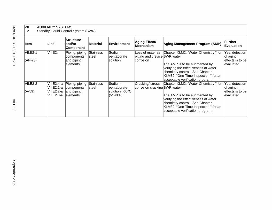
VII AUXILIARY SYSTEMS E2 Standby Liquid Control System (BWR)
Item Link Structure and/or Component
Material Environment Aging Effect/ Mechanism Aging Management Program (AMP) Further
Evaluation
VII.E2-1
(AP-73)
VII.E2. Piping, piping components, and piping elements
Stainless steel
Sodium pentaborate solution
Loss of material/ pitting and crevice corrosion
Chapter XI.M2, “Water Chemistry,” for BWR water
The AMP is to be augmented by verifying the effectiveness of water chemistry control. See Chapter XI.M32, “One-Time Inspection,” for an acceptable verification program.
Yes, detection of aging effects is to be evaluated
VII.E2-2
(A-59)
VII.E2.4-a VII.E2.1-a VII.E2.2-a VII.E2.3-a
Piping, piping components, and piping elements
Stainless steel
Sodium pentaborate solution >60°C (>140°F)
Cracking/ stress corrosion cracking
Chapter XI.M2, “Water Chemistry,” for BWR water
The AMP is to be augmented by verifying the effectiveness of water chemistry control. See Chapter XI.M32, “One-Time Inspection,” for an acceptable verification program.
Yes, detection of aging effects is to be evaluated
Draft N
UR
EG
-1801, Rev. 1
VII E
2-2 S
eptember 2005
E3. REACTOR WATER CLEANUP SYSTEM (BOILING WATER REACTOR)
Systems, Structures, and Components
This section discusses the reactor water cleanup (RWCU) system, which provides for cleanup and particulate removal from the recirculating reactor coolant in all boiling water reactors (BWRs). Some plants may not include the RWCU system in the scope of license renewal, while other plants may include the RWCU system because it is associated with safety-related functions.
Based on Regulatory Guide 1.26, “Quality Group Classifications and Standards for Water-, Steam-, and Radioactive-Waste-Containing Components of Nuclear Power Plants,” the portion of the RWCU system extending from the reactor coolant recirculation system up to and including the containment isolation valves for are covered in IV.C1. The remainder of the system outboard of the isolation valves is governed by Group C Quality Standards. In this table, only aging management programs for RWCU-related piping and components outboard of the isolation valves are evaluated. The aging management program for containment isolation valves in the RWCU system is evaluated in IV.C1, which concerns the reactor coolant pressure boundary in BWRs.
Pump and valve internals perform their intended functions with moving parts or with a change in configuration. They are also subject to replacement based on qualified life or specified time period. Pursuant to 10 CFR 54.21(a)(1), therefore, they are not subject to an aging management review.
Aging management programs for the degradation of external surfaces of components and miscellaneous bolting are included in VII.I. Common miscellaneous material/environment combinations where aging effects are not expected to degrade the ability of the structure or component to perform its intended function for the extended period of operation are included in VII.J.
The system piping includes all pipe sizes, including instrument piping.
System Interfaces
The systems that interface with the BWR reactor water cleanup system include the reactor coolant pressure boundary (IV.C1), the closed-cycle cooling water system (VII.C2), and the condensate system (VIII.E).
September 2005 VII E3-1 Draft NUREG-1801, Rev. 1

VII AUXILIARY SYSTEMS E3 Reactor Water Cleanup System
Item Link Structure and/or Component
Material Environment Aging Effect/ Mechanism Aging Management Program (AMP) Further
Evaluation
VII.E3-1
(A-67)
VII.E3.4-b Heat exchanger components
Stainless steel; steel with stainless steel cladding
Closed cycle cooling water
Loss of material/ microbiologically influenced corrosion
Chapter XI.M21, “Closed-Cycle Cooling Water System”
No
VII.E3-2
(A-68)
VII.E3.4-a Heat exchanger components
Stainless steel; steel with stainless steel cladding
Closed cycle cooling water >60°C (>140°F)
Cracking/ stress corrosion cracking
Chapter XI.M21, “Closed-Cycle Cooling Water System”
No
VII.E3-3
(A-71)
VII.E3.4-a Heat exchanger components
Stainless steel; steel with stainless steel cladding
Treated water >60°C (>140°F)
Cracking/ stress corrosion cracking
A plant-specific aging management program is to be evaluated.
Yes, plant-specific
VII.E3-4
(A-63)
VII.E3. Heat exchanger components
Steel Closed cycle cooling water
Loss of material/ general, pitting, crevice, and galvanic corrosion
Chapter XI.M21, “Closed-Cycle Cooling Water System”
No
VII.E3-5
(AP-63)
VII.E3. Heat exchanger tubes
Stainless steel
Closed cycle cooling water
Reduction of heat transfer/ fouling
Chapter XI.M21, “Closed-Cycle Cooling Water System”
No
VII.E3-6
(AP-62)
VII.E3. Heat exchanger tubes
Stainless steel
Treated water Reduction of heat transfer/ fouling
Chapter XI.M2, “Water Chemistry”
The AMP is to be augmented by verifying the effectiveness of water chemistry control. See Chapter XI.M32, “One-Time Inspection,” for an acceptable verification program.
Yes, detection of aging effects is to be evaluated
Draft N
UR
EG
-1801, Rev. 1
VII E
3-2 S
eptember 2005

VII AUXILIARY SYSTEMS E3 Reactor Water Cleanup System
Item Link Structure and/or Component
Material Environment Aging Effect/ Mechanism Aging Management Program (AMP) Further
Evaluation
VII.E3-7
(AP-38)
VII.E3. Piping, piping components, and piping elements
Aluminum Treated water Loss of material/ pitting and crevice corrosion
Chapter XI.M2, "Water Chemistry"
The AMP is to be augmented by verifying the effectiveness of water chemistry control. See Chapter XI.M32, “One-Time Inspection,” for an acceptable verification program.
Yes, detection of aging effects is to be evaluated
VII.E3-8
(AP-12)
VII.E3. Piping, piping components, and piping elements
Copper alloy Closed cycle cooling water
Loss of material/ pitting, crevice, and galvanic corrosion
Chapter XI.M21, “Closed-Cycle Cooling Water System”
No
VII.E3-9
(AP-64)
VII.E3. Piping, piping components, and piping elements
Copper alloy Treated water Loss of material/ pitting, crevice, and galvanic corrosion
Chapter XI.M2, “Water Chemistry,” for BWR water
The AMP is to be augmented by verifying the effectiveness of water chemistry control. See Chapter XI.M32, “One-Time Inspection,” for an acceptable verification program.
Yes, detection of aging effects is to be evaluated
VII.E3-10
(AP-43)
VII.E3. Piping, piping components, and piping elements
Copper alloy >15% Zn
Closed cycle cooling water
Loss of material/ selective leaching
Chapter XI.M33, “Selective Leaching of Materials”
No
VII.E3-11
(AP-32)
VII.E3. Piping, piping components, and piping elements
Copper alloy >15% Zn
Treated water Loss of material/ selective leaching
Chapter XI.M33, “Selective Leaching of Materials”
No
VII.E3-12
(AP-31)
VII.E3. Piping, piping components, and piping elements
Gray cast iron
Treated water Loss of material/ selective leaching
Chapter XI.M33, “Selective Leaching of Materials”
No
Septem
ber 2005 V
II E3-3
Draft N
UR
EG
-1801, Rev. 1
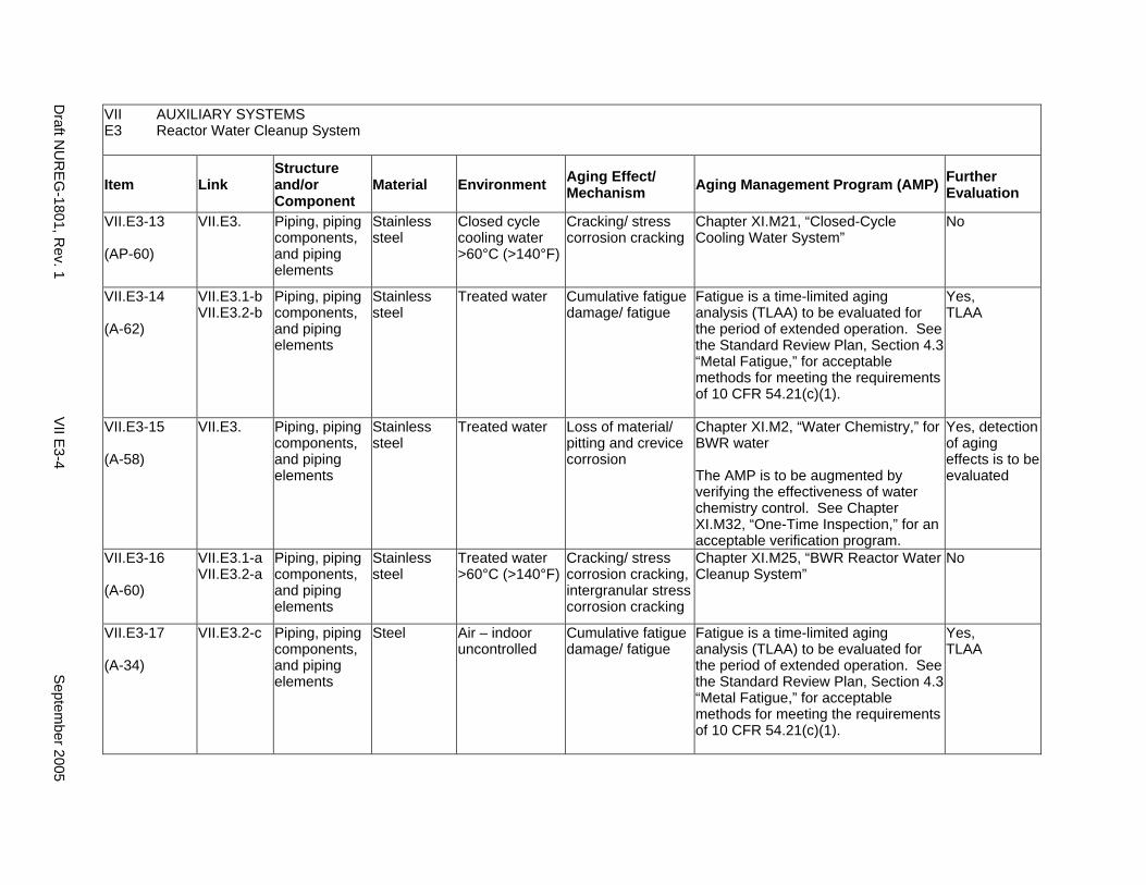
VII AUXILIARY SYSTEMS E3 Reactor Water Cleanup System
Item Link Structure and/or Component
Material Environment Aging Effect/ Mechanism Aging Management Program (AMP) Further
Evaluation
VII.E3-13
(AP-60)
VII.E3. Piping, piping components, and piping elements
Stainless steel
Closed cycle cooling water >60°C (>140°F)
Cracking/ stress corrosion cracking
Chapter XI.M21, “Closed-Cycle Cooling Water System”
No
VII.E3-14
(A-62)
VII.E3.1-b VII.E3.2-b
Piping, piping components, and piping elements
Stainless steel
Treated water Cumulative fatigue damage/ fatigue
Fatigue is a time-limited aging analysis (TLAA) to be evaluated for the period of extended operation. See the Standard Review Plan, Section 4.3 “Metal Fatigue,” for acceptable methods for meeting the requirements of 10 CFR 54.21(c)(1).
Yes, TLAA
VII.E3-15
(A-58)
VII.E3. Piping, piping components, and piping elements
Stainless steel
Treated water Loss of material/ pitting and crevice corrosion
Chapter XI.M2, “Water Chemistry,” for BWR water
The AMP is to be augmented by verifying the effectiveness of water chemistry control. See Chapter XI.M32, “One-Time Inspection,” for an acceptable verification program.
Yes, detection of aging effects is to be evaluated
VII.E3-16
(A-60)
VII.E3.1-a VII.E3.2-a
Piping, piping components, and piping elements
Stainless steel
Treated water >60°C (>140°F)
Cracking/ stress corrosion cracking, intergranular stress corrosion cracking
Chapter XI.M25, “BWR Reactor Water Cleanup System”
No
VII.E3-17
(A-34)
VII.E3.2-c Piping, piping components, and piping elements
Steel Air – indoor uncontrolled
Cumulative fatigue damage/ fatigue
Fatigue is a time-limited aging analysis (TLAA) to be evaluated for the period of extended operation. See the Standard Review Plan, Section 4.3 “Metal Fatigue,” for acceptable methods for meeting the requirements of 10 CFR 54.21(c)(1).
Yes, TLAA
Draft N
UR
EG
-1801, Rev. 1
VII E
3-4 S
eptember 2005
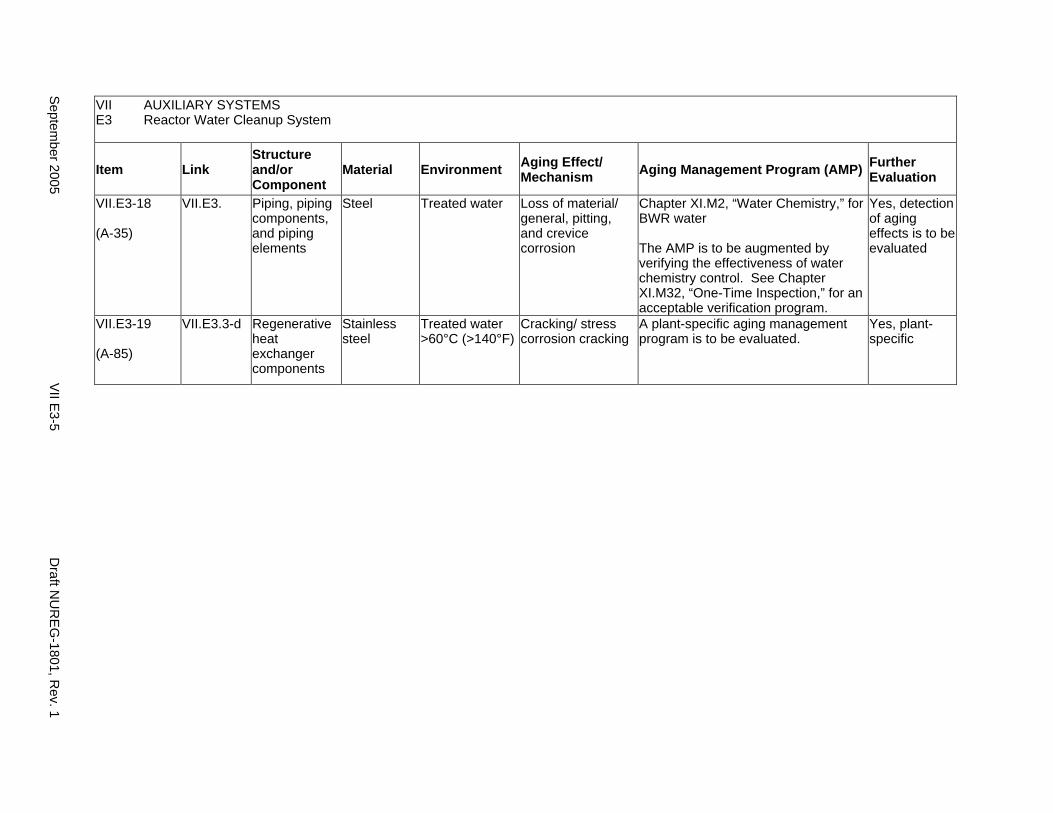
VII AUXILIARY SYSTEMS E3 Reactor Water Cleanup System
Item Link Structure and/or Component
Material Environment Aging Effect/ Mechanism Aging Management Program (AMP) Further
Evaluation
VII.E3-18
(A-35)
VII.E3. Piping, piping components, and piping elements
Steel Treated water Loss of material/ general, pitting, and crevice corrosion
Chapter XI.M2, “Water Chemistry,” for BWR water
The AMP is to be augmented by verifying the effectiveness of water chemistry control. See Chapter XI.M32, “One-Time Inspection,” for an acceptable verification program.
Yes, detection of aging effects is to be evaluated
VII.E3-19
(A-85)
VII.E3.3-d Regenerative heat exchanger components
Stainless steel
Treated water >60°C (>140°F)
Cracking/ stress corrosion cracking
A plant-specific aging management program is to be evaluated.
Yes, plant-specific
Septem
ber 2005 V
II E3-5
Draft N
UR
EG
-1801, Rev. 1
This Page Intentionally Left Blank
Draft NUREG-1801, Rev. 1 VII E3-6 September 2005
E4. SHUTDOWN COOLING SYSTEM (OLDER BWR)
Systems, Structures, and Components
This section discusses the shutdown cooling (SDC) system for older vintage boiling water reactors (BWRs) and consists of piping and fittings, the SDC system pump, the heat exchanger, and valves.
Based on Regulatory Guide 1.26, “Quality Group Classifications and Standards for Water-, Steam-, and Radioactive-Waste-Containing Components of Nuclear Power Plants,” all components that comprise the SDC system are governed by Group B Quality Standards. Portions of the SDC system extending from the reactor coolant pressure boundary up to and including the containment isolation valves are governed by Group A Quality Standards and are covered in IV.C1.
Pump and valve internals perform their intended functions with moving parts or with a change in configuration. They are also subject to replacement based on qualified life or specified time period. Pursuant to 10 CFR 54.21(a)(1), therefore, they are not subject to an aging management review.
Aging management programs for the degradation of external surfaces of components and miscellaneous bolting are included in VII.I. Common miscellaneous material/environment combinations where aging effects are not expected to degrade the ability of the structure or component to perform its intended function for the extended period of operation are included in VII.J.
The system piping includes all pipe sizes, including instrument piping.
System Interfaces
The systems that interface with the SDC system include the reactor coolant pressure boundary (IV.C1) and the closed-cycle cooling water system (VII.C2).
September 2005 VII E4-1 Draft NUREG-1801, Rev. 1
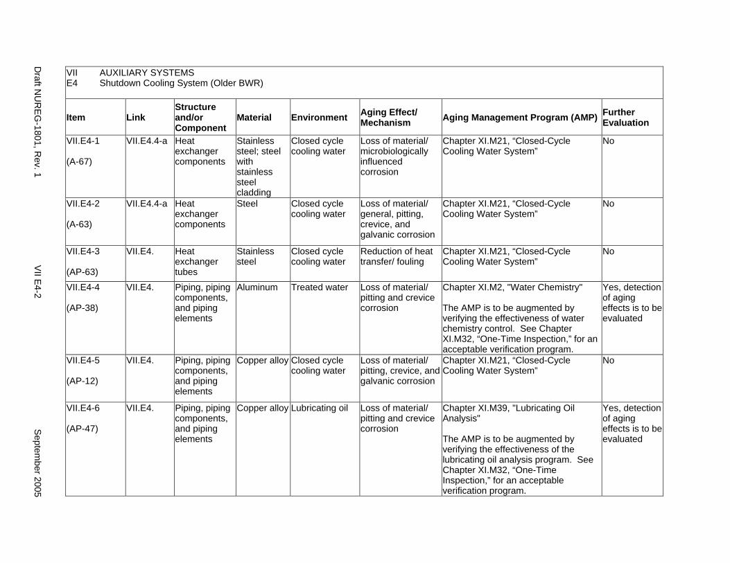
VII AUXILIARY SYSTEMS E4 Shutdown Cooling System (Older BWR)
Item Link Structure and/or Component
Material Environment Aging Effect/ Mechanism Aging Management Program (AMP) Further
Evaluation
VII.E4-1
(A-67)
VII.E4.4-a Heat exchanger components
Stainless steel; steel with stainless steel cladding
Closed cycle cooling water
Loss of material/ microbiologically influenced corrosion
Chapter XI.M21, “Closed-Cycle Cooling Water System”
No
VII.E4-2
(A-63)
VII.E4.4-a Heat exchanger components
Steel Closed cycle cooling water
Loss of material/ general, pitting, crevice, and galvanic corrosion
Chapter XI.M21, “Closed-Cycle Cooling Water System”
No
VII.E4-3
(AP-63)
VII.E4. Heat exchanger tubes
Stainless steel
Closed cycle cooling water
Reduction of heat transfer/ fouling
Chapter XI.M21, “Closed-Cycle Cooling Water System”
No
VII.E4-4
(AP-38)
VII.E4. Piping, piping components, and piping elements
Aluminum Treated water Loss of material/ pitting and crevice corrosion
Chapter XI.M2, "Water Chemistry"
The AMP is to be augmented by verifying the effectiveness of water chemistry control. See Chapter XI.M32, “One-Time Inspection,” for an acceptable verification program.
Yes, detection of aging effects is to be evaluated
VII.E4-5
(AP-12)
VII.E4. Piping, piping components, and piping elements
Copper alloy Closed cycle cooling water
Loss of material/ pitting, crevice, and galvanic corrosion
Chapter XI.M21, “Closed-Cycle Cooling Water System”
No
VII.E4-6
(AP-47)
VII.E4. Piping, piping components, and piping elements
Copper alloy Lubricating oil Loss of material/ pitting and crevice corrosion
Chapter XI.M39, "Lubricating Oil Analysis"
The AMP is to be augmented by verifying the effectiveness of the lubricating oil analysis program. See Chapter XI.M32, “One-Time Inspection,” for an acceptable verification program.
Yes, detection of aging effects is to be evaluated
Draft N
UR
EG
-1801, Rev. 1
VII E
4-2 S
eptember 2005

VII AUXILIARY SYSTEMS E4 Shutdown Cooling System (Older BWR)
Item Link Structure and/or Component
Material Environment Aging Effect/ Mechanism Aging Management Program (AMP) Further
Evaluation
VII.E4-7
(AP-64)
VII.E4. Piping, piping components, and piping elements
Copper alloy Treated water Loss of material/ pitting, crevice, and galvanic corrosion
Chapter XI.M2, “Water Chemistry,” for BWR water
The AMP is to be augmented by verifying the effectiveness of water chemistry control. See Chapter XI.M32, “One-Time Inspection,” for an acceptable verification program.
Yes, detection of aging effects is to be evaluated
VII.E4-8
(AP-43)
VII.E4. Piping, piping components, and piping elements
Copper alloy >15% Zn
Closed cycle cooling water
Loss of material/ selective leaching
Chapter XI.M33, “Selective Leaching of Materials”
No
VII.E4-9
(AP-32)
VII.E4. Piping, piping components, and piping elements
Copper alloy >15% Zn
Treated water Loss of material/ selective leaching
Chapter XI.M33, “Selective Leaching of Materials”
No
VII.E4-10
(AP-31)
VII.E4. Piping, piping components, and piping elements
Gray cast iron
Treated water Loss of material/ selective leaching
Chapter XI.M33, “Selective Leaching of Materials”
No
VII.E4-11
(AP-60)
VII.E4. Piping, piping components, and piping elements
Stainless steel
Closed cycle cooling water >60°C (>140°F)
Cracking/ stress corrosion cracking
Chapter XI.M21, “Closed-Cycle Cooling Water System”
No
Septem
ber 2005 V
II E4-3
Draft N
UR
EG
-1801, Rev. 1
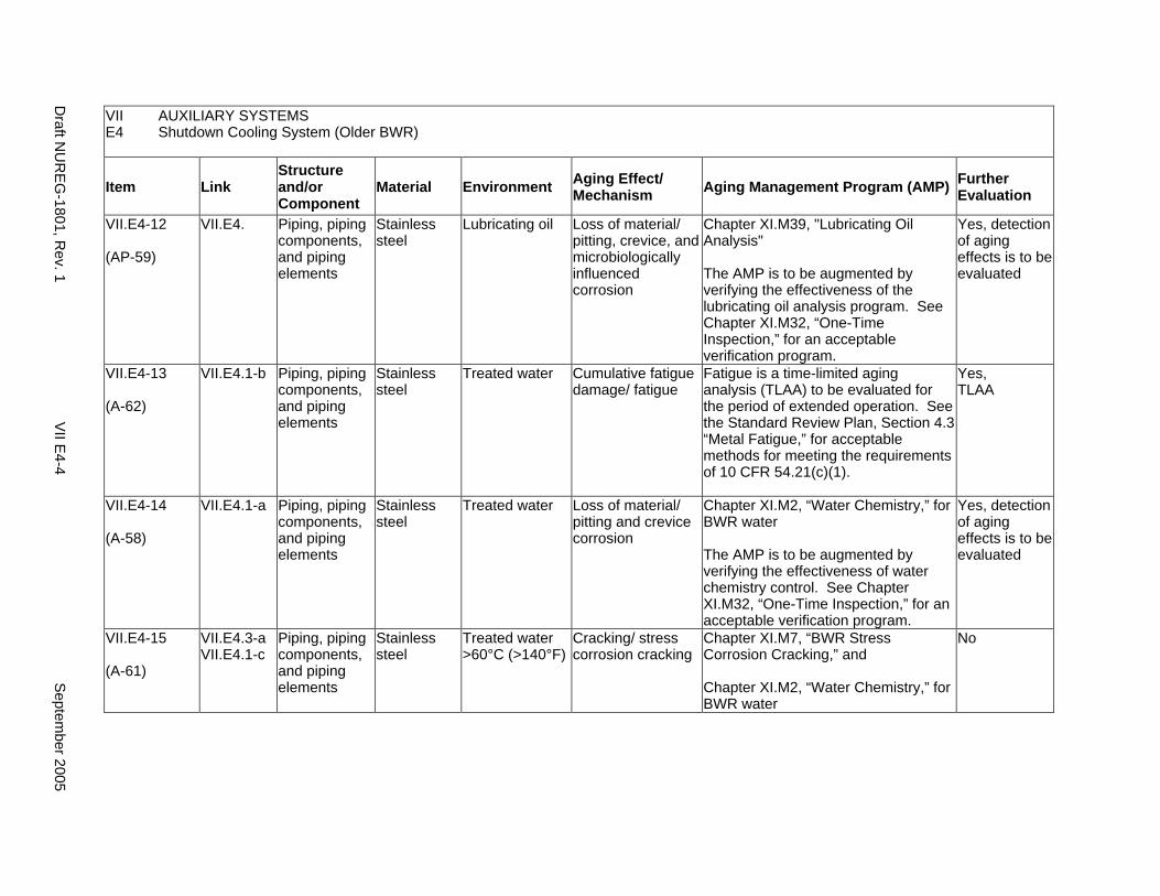
VII AUXILIARY SYSTEMS E4 Shutdown Cooling System (Older BWR)
Item Link Structure and/or Component
Material Environment Aging Effect/ Mechanism Aging Management Program (AMP) Further
Evaluation
VII.E4-12
(AP-59)
VII.E4. Piping, piping components, and piping elements
Stainless steel
Lubricating oil Loss of material/ pitting, crevice, and microbiologically influenced corrosion
Chapter XI.M39, "Lubricating Oil Analysis"
The AMP is to be augmented by verifying the effectiveness of the lubricating oil analysis program. See Chapter XI.M32, “One-Time Inspection,” for an acceptable verification program.
Yes, detection of aging effects is to be evaluated
VII.E4-13
(A-62)
VII.E4.1-b Piping, piping components, and piping elements
Stainless steel
Treated water Cumulative fatigue damage/ fatigue
Fatigue is a time-limited aging analysis (TLAA) to be evaluated for the period of extended operation. See the Standard Review Plan, Section 4.3 “Metal Fatigue,” for acceptable methods for meeting the requirements of 10 CFR 54.21(c)(1).
Yes, TLAA
VII.E4-14
(A-58)
VII.E4.1-a Piping, piping components, and piping elements
Stainless steel
Treated water Loss of material/ pitting and crevice corrosion
Chapter XI.M2, “Water Chemistry,” for BWR water
The AMP is to be augmented by verifying the effectiveness of water chemistry control. See Chapter XI.M32, “One-Time Inspection,” for an acceptable verification program.
Yes, detection of aging effects is to be evaluated
VII.E4-15
(A-61)
VII.E4.3-a VII.E4.1-c
Piping, piping components, and piping elements
Stainless steel
Treated water >60°C (>140°F)
Cracking/ stress corrosion cracking
Chapter XI.M7, “BWR Stress Corrosion Cracking,” and
Chapter XI.M2, “Water Chemistry,” for BWR water
No
Draft N
UR
EG
-1801, Rev. 1
VII E
4-4 S
eptember 2005
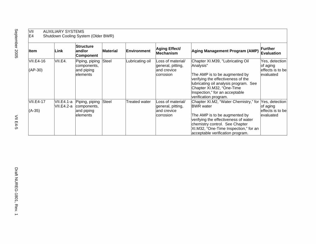
VII AUXILIARY SYSTEMS E4 Shutdown Cooling System (Older BWR)
Item Link Structure and/or Component
Material Environment Aging Effect/ Mechanism Aging Management Program (AMP) Further
Evaluation
VII.E4-16
(AP-30)
VII.E4. Piping, piping components, and piping elements
Steel Lubricating oil Loss of material/ general, pitting, and crevice corrosion
Chapter XI.M39, "Lubricating Oil Analysis"
The AMP is to be augmented by verifying the effectiveness of the lubricating oil analysis program. See Chapter XI.M32, “One-Time Inspection,” for an acceptable verification program.
Yes, detection of aging effects is to be evaluated
VII.E4-17
(A-35)
VII.E4.1-a VII.E4.2-a
Piping, piping components, and piping elements
Steel Treated water Loss of material/ general, pitting, and crevice corrosion
Chapter XI.M2, “Water Chemistry,” for BWR water
The AMP is to be augmented by verifying the effectiveness of water chemistry control. See Chapter XI.M32, “One-Time Inspection,” for an acceptable verification program.
Yes, detection of aging effects is to be evaluated
Septem
ber 2005 V
II E4-5
Draft N
UR
EG
-1801, Rev. 1

This Page Intentionally Left Blank
Draft NUREG-1801, Rev. 1 VII E4-6 September 2005
F1. CONTROL ROOM AREA VENTILATION SYSTEM
Systems, Structures, and Components
This section discusses the control room area ventilation system (with warm moist air as the normal environment), which contains ducts, piping and fittings, equipment frames and housings, flexible collars and seals, filters, and heating and cooling air handlers. Based on Regulatory Guide 1.26, “Quality Group Classifications and Standards for Water-, Steam-, and Radioactive-Waste-Containing Components of Nuclear Power Plants,” all components that comprise the control room area ventilation system are governed by Group B Quality Standards.
With respect to filters and seals, these items are to be addressed consistent with the Nuclear Regulatory Commission (NRC) position on consumables, provided in the NRC letter from Christopher I. Grimes to Douglas J. Walters of Nuclear Energy Institute (NEI), dated March 10, 2000. Specifically, components that function as system filters and seals are typically replaced based on performance or condition monitoring that identifies whether these components are at the end of their qualified lives and may be excluded, on a plant-specific basis, from an aging management review under 10 CFR 54.21(a)(1)(ii). As part of the methodology description, the application should identify the standards that are relied on for replacement, for example, National Fire Protection Association (NFPA) standards for fire protection equipment.
Aging management programs for the degradation of external surfaces of components and miscellaneous bolting are included in VII.I. Common miscellaneous material/environment combinations where aging effects are not expected to degrade the ability of the structure or component to perform its intended function for the extended period of operation are included in VII.J.
The system piping includes all pipe sizes, including instrument piping.
System Interfaces
The system that interfaces with the control room area ventilation system is the auxiliary and radwaste area ventilation system (VII.F2). The cooling coils receive their cooling water from other systems, such as the hot water heating system or the chilled water cooling system.
September 2005 VII F1-1 Draft NUREG-1801, Rev. 1
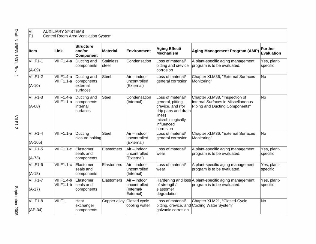
VII AUXILIARY SYSTEMS F1 Control Room Area Ventilation System
Item Link Structure and/or Component
Material Environment Aging Effect/ Mechanism Aging Management Program (AMP) Further
Evaluation
VII.F1-1
(A-09)
VII.F1.4-a Ducting and components
Stainless steel
Condensation Loss of material/ pitting and crevice corrosion
A plant-specific aging management program is to be evaluated.
Yes, plant-specific
VII.F1-2
(A-10)
VII.F1.4-a VII.F1.1-a
Ducting and components external surfaces
Steel Air – indoor uncontrolled (External)
Loss of material/ general corrosion
Chapter XI.M36, "External Surfaces Monitoring"
No
VII.F1-3
(A-08)
VII.F1.4-a VII.F1.1-a
Ducting and components internal surfaces
Steel Condensation (Internal)
Loss of material/ general, pitting, crevice, and (for drip pans and drain lines) microbiologically influenced corrosion
Chapter XI.M38, "Inspection of Internal Surfaces in Miscellaneous Piping and Ducting Components"
No
VII.F1-4
(A-105)
VII.F1.1-a Ducting closure bolting
Steel Air – indoor uncontrolled (External)
Loss of material/ general corrosion
Chapter XI.M36, "External Surfaces Monitoring"
No
VII.F1-5
(A-73)
VII.F1.1-c Elastomer seals and components
Elastomers Air – indoor uncontrolled (External)
Loss of material/ wear
A plant-specific aging management program is to be evaluated.
Yes, plant-specific
VII.F1-6
(A-18)
VII.F1.1-c Elastomer seals and components
Elastomers Air – indoor uncontrolled (Internal)
Loss of material/ wear
A plant-specific aging management program is to be evaluated.
Yes, plant-specific
VII.F1-7
(A-17)
VII.F1.4-b VII.F1.1-b
Elastomer seals and components
Elastomers Air – indoor uncontrolled (Internal/ External)
Hardening and loss of strength/ elastomer degradation
A plant-specific aging management program is to be evaluated.
Yes, plant-specific
VII.F1-8
(AP-34)
VII.F1. Heat exchanger components
Copper alloy Closed cycle cooling water
Loss of material/ pitting, crevice, and galvanic corrosion
Chapter XI.M21, “Closed-Cycle Cooling Water System”
No
Draft N
UR
EG
-1801, Rev. 1
VII F1-2
Septem
ber 2005
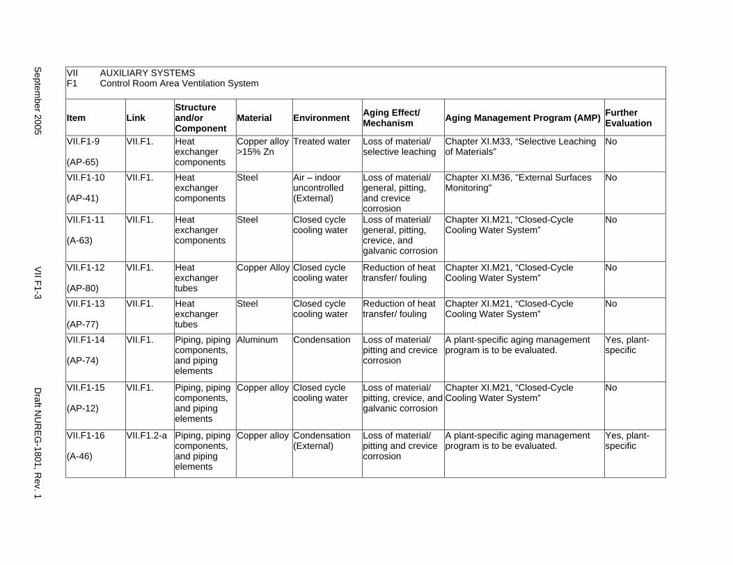
VII AUXILIARY SYSTEMS F1 Control Room Area Ventilation System
Item Link Structure and/or Component
Material Environment Aging Effect/ Mechanism Aging Management Program (AMP) Further
Evaluation
VII.F1-9
(AP-65)
VII.F1. Heat exchanger components
Copper alloy >15% Zn
Treated water Loss of material/ selective leaching
Chapter XI.M33, “Selective Leaching of Materials”
No
VII.F1-10
(AP-41)
VII.F1. Heat exchanger components
Steel Air – indoor uncontrolled (External)
Loss of material/ general, pitting, and crevice corrosion
Chapter XI.M36, "External Surfaces Monitoring"
No
VII.F1-11
(A-63)
VII.F1. Heat exchanger components
Steel Closed cycle cooling water
Loss of material/ general, pitting, crevice, and galvanic corrosion
Chapter XI.M21, “Closed-Cycle Cooling Water System”
No
VII.F1-12
(AP-80)
VII.F1. Heat exchanger tubes
Copper Alloy Closed cycle cooling water
Reduction of heat transfer/ fouling
Chapter XI.M21, “Closed-Cycle Cooling Water System”
No
VII.F1-13
(AP-77)
VII.F1. Heat exchanger tubes
Steel Closed cycle cooling water
Reduction of heat transfer/ fouling
Chapter XI.M21, “Closed-Cycle Cooling Water System”
No
VII.F1-14
(AP-74)
VII.F1. Piping, piping components, and piping elements
Aluminum Condensation Loss of material/ pitting and crevice corrosion
A plant-specific aging management program is to be evaluated.
Yes, plant-specific
VII.F1-15
(AP-12)
VII.F1. Piping, piping components, and piping elements
Copper alloy Closed cycle cooling water
Loss of material/ pitting, crevice, and galvanic corrosion
Chapter XI.M21, “Closed-Cycle Cooling Water System”
No
VII.F1-16
(A-46)
VII.F1.2-a Piping, piping components, and piping elements
Copper alloy Condensation (External)
Loss of material/ pitting and crevice corrosion
A plant-specific aging management program is to be evaluated.
Yes, plant-specific
Septem
ber 2005 V
II F1-3 D
raft NU
RE
G-1801, R
ev. 1
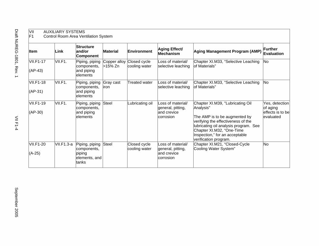
VII AUXILIARY SYSTEMS F1 Control Room Area Ventilation System
Item Link Structure and/or Component
Material Environment Aging Effect/ Mechanism Aging Management Program (AMP) Further
Evaluation
VII.F1-17
(AP-43)
VII.F1. Piping, piping components, and piping elements
Copper alloy >15% Zn
Closed cycle cooling water
Loss of material/ selective leaching
Chapter XI.M33, “Selective Leaching of Materials”
No
VII.F1-18
(AP-31)
VII.F1. Piping, piping components, and piping elements
Gray cast iron
Treated water Loss of material/ selective leaching
Chapter XI.M33, “Selective Leaching of Materials”
No
VII.F1-19
(AP-30)
VII.F1. Piping, piping components, and piping elements
Steel Lubricating oil Loss of material/ general, pitting, and crevice corrosion
Chapter XI.M39, "Lubricating Oil Analysis"
The AMP is to be augmented by verifying the effectiveness of the lubricating oil analysis program. See Chapter XI.M32, “One-Time Inspection,” for an acceptable verification program.
Yes, detection of aging effects is to be evaluated
VII.F1-20
(A-25)
VII.F1.3-a Piping, piping components, piping elements, and tanks
Steel Closed cycle cooling water
Loss of material/ general, pitting, and crevice corrosion
Chapter XI.M21, “Closed-Cycle Cooling Water System”
No
Draft N
UR
EG
-1801, Rev. 1
VII F1-4
Septem
ber 2005
F2. Auxiliary and Radwaste Area Ventilation System
Systems, Structures, and Components
This section discusses the auxiliary and radwaste areas ventilation systems (with warm moist air as the normal environment) and contains ducts, piping and fittings, equipment frames and housings, flexible collars and seals, filters, and heating and cooling air handlers. Based on Regulatory Guide 1.26, “Quality Group Classifications and Standards for Water-, Steam-, and Radioactive-Waste-Containing Components of Nuclear Power Plants,” all components that comprise the auxiliary and radwaste area ventilation system are governed by Group B Quality Standards.
With respect to filters and seals, these items are to be addressed consistent with the NRC position on consumables, provided in the NRC letter from Christopher I. Grimes to Douglas J. Walters of Nuclear Energy Institute (NEI), dated March 10, 2000. Specifically, components that function as system filters and seals are typically replaced based on performance or condition monitoring that identifies whether these components are at the end of their qualified lives and may be excluded, on a plant-specific basis, from an aging management review under 10 CFR 54.21(a)(1)(ii). As part of the methodology description, the application should identify the standards that are relied on for replacement, for example, National Fire Protection Association (NFPA) standards for fire protection equipment.
Aging management programs for the degradation of external surfaces of components and miscellaneous bolting are included in VII.I. Common miscellaneous material/environment combinations where aging effects are not expected to degrade the ability of the structure or component to perform its intended function for the extended period of operation are included in VII.J.
The system piping includes all pipe sizes, including instrument piping.
System Interfaces
The systems that interface with the auxiliary and radwaste area ventilation system are the control room area ventilation system (VII.F1) and the diesel generator building ventilation system (VII.F4). The cooling coils receive their cooling water from other systems, such as the hot water heating system or the chilled water cooling system.
September 2005 VII F2-1 Draft NUREG-1801, Rev. 1
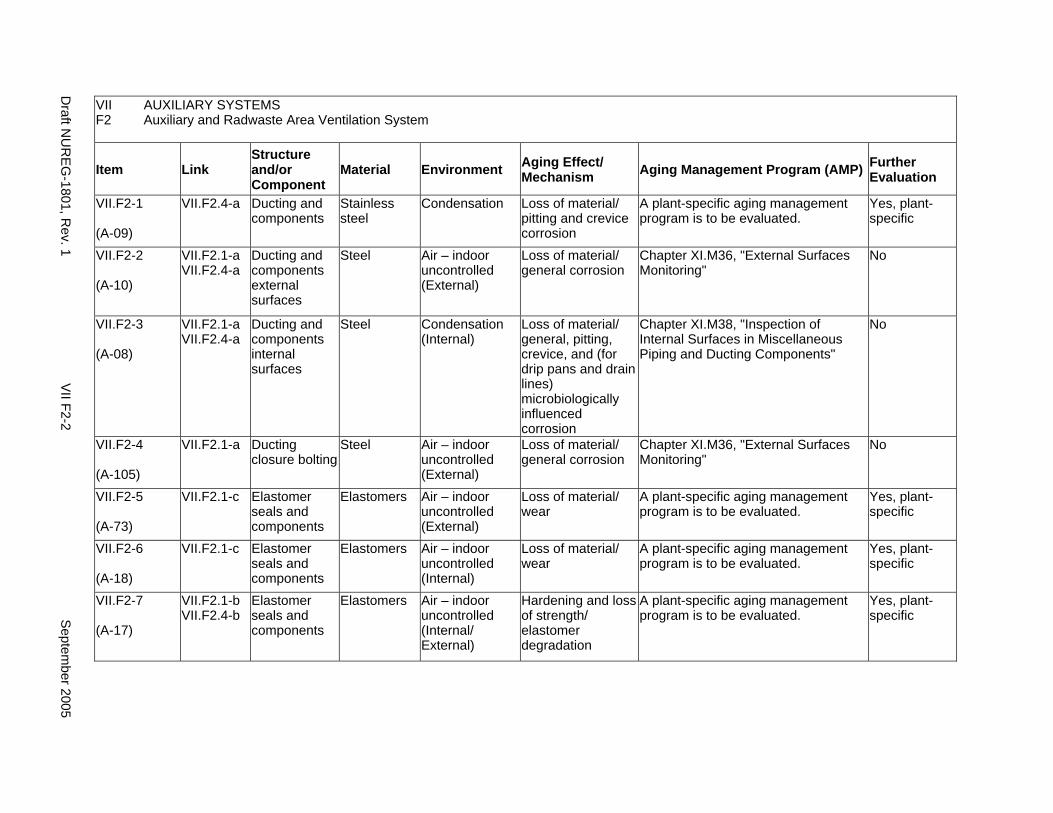
VII AUXILIARY SYSTEMS F2 Auxiliary and Radwaste Area Ventilation System
Item Link Structure and/or Component
Material Environment Aging Effect/ Mechanism Aging Management Program (AMP) Further
Evaluation
VII.F2-1
(A-09)
VII.F2.4-a Ducting and components
Stainless steel
Condensation Loss of material/ pitting and crevice corrosion
A plant-specific aging management program is to be evaluated.
Yes, plant-specific
VII.F2-2
(A-10)
VII.F2.1-a VII.F2.4-a
Ducting and components external surfaces
Steel Air – indoor uncontrolled (External)
Loss of material/ general corrosion
Chapter XI.M36, "External Surfaces Monitoring"
No
VII.F2-3
(A-08)
VII.F2.1-a VII.F2.4-a
Ducting and components internal surfaces
Steel Condensation (Internal)
Loss of material/ general, pitting, crevice, and (for drip pans and drain lines) microbiologically influenced corrosion
Chapter XI.M38, "Inspection of Internal Surfaces in Miscellaneous Piping and Ducting Components"
No
VII.F2-4
(A-105)
VII.F2.1-a Ducting closure bolting
Steel Air – indoor uncontrolled (External)
Loss of material/ general corrosion
Chapter XI.M36, "External Surfaces Monitoring"
No
VII.F2-5
(A-73)
VII.F2.1-c Elastomer seals and components
Elastomers Air – indoor uncontrolled (External)
Loss of material/ wear
A plant-specific aging management program is to be evaluated.
Yes, plant-specific
VII.F2-6
(A-18)
VII.F2.1-c Elastomer seals and components
Elastomers Air – indoor uncontrolled (Internal)
Loss of material/ wear
A plant-specific aging management program is to be evaluated.
Yes, plant-specific
VII.F2-7
(A-17)
VII.F2.1-b VII.F2.4-b
Elastomer seals and components
Elastomers Air – indoor uncontrolled (Internal/ External)
Hardening and loss of strength/ elastomer degradation
A plant-specific aging management program is to be evaluated.
Yes, plant-specific
Draft N
UR
EG
-1801, Rev. 1
VII F2-2
Septem
ber 2005
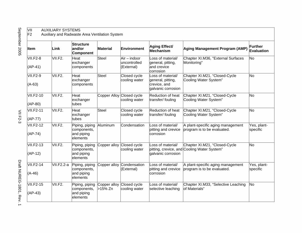
VII AUXILIARY SYSTEMS F2 Auxiliary and Radwaste Area Ventilation System
Item Link Structure and/or Component
Material Environment Aging Effect/ Mechanism Aging Management Program (AMP) Further
Evaluation
VII.F2-8
(AP-41)
VII.F2. Heat exchanger components
Steel Air – indoor uncontrolled (External)
Loss of material/ general, pitting, and crevice corrosion
Chapter XI.M36, "External Surfaces Monitoring"
No
VII.F2-9
(A-63)
VII.F2. Heat exchanger components
Steel Closed cycle cooling water
Loss of material/ general, pitting, crevice, and galvanic corrosion
Chapter XI.M21, “Closed-Cycle Cooling Water System”
No
VII.F2-10
(AP-80)
VII.F2. Heat exchanger tubes
Copper Alloy Closed cycle cooling water
Reduction of heat transfer/ fouling
Chapter XI.M21, “Closed-Cycle Cooling Water System”
No
VII.F2-11
(AP-77)
VII.F2. Heat exchanger tubes
Steel Closed cycle cooling water
Reduction of heat transfer/ fouling
Chapter XI.M21, “Closed-Cycle Cooling Water System”
No
VII.F2-12
(AP-74)
VII.F2. Piping, piping components, and piping elements
Aluminum Condensation Loss of material/ pitting and crevice corrosion
A plant-specific aging management program is to be evaluated.
Yes, plant-specific
VII.F2-13
(AP-12)
VII.F2. Piping, piping components, and piping elements
Copper alloy Closed cycle cooling water
Loss of material/ pitting, crevice, and galvanic corrosion
Chapter XI.M21, “Closed-Cycle Cooling Water System”
No
VII.F2-14
(A-46)
VII.F2.2-a Piping, piping components, and piping elements
Copper alloy Condensation (External)
Loss of material/ pitting and crevice corrosion
A plant-specific aging management program is to be evaluated.
Yes, plant-specific
VII.F2-15
(AP-43)
VII.F2. Piping, piping components, and piping elements
Copper alloy >15% Zn
Closed cycle cooling water
Loss of material/ selective leaching
Chapter XI.M33, “Selective Leaching of Materials”
No
Septem
ber 2005 V
II F2-3 D
raft NU
RE
G-1801, R
ev. 1
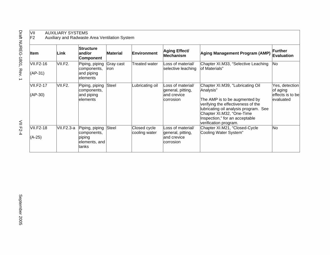
VII AUXILIARY SYSTEMS F2 Auxiliary and Radwaste Area Ventilation System
Item Link Structure and/or Component
Material Environment Aging Effect/ Mechanism Aging Management Program (AMP) Further
Evaluation
VII.F2-16
(AP-31)
VII.F2. Piping, piping components, and piping elements
Gray cast iron
Treated water Loss of material/ selective leaching
Chapter XI.M33, “Selective Leaching of Materials”
No
VII.F2-17
(AP-30)
VII.F2. Piping, piping components, and piping elements
Steel Lubricating oil Loss of material/ general, pitting, and crevice corrosion
Chapter XI.M39, "Lubricating Oil Analysis"
The AMP is to be augmented by verifying the effectiveness of the lubricating oil analysis program. See Chapter XI.M32, “One-Time Inspection,” for an acceptable verification program.
Yes, detection of aging effects is to be evaluated
VII.F2-18
(A-25)
VII.F2.3-a Piping, piping components, piping elements, and tanks
Steel Closed cycle cooling water
Loss of material/ general, pitting, and crevice corrosion
Chapter XI.M21, “Closed-Cycle Cooling Water System”
No
Draft N
UR
EG
-1801, Rev. 1
VII F2-4
Septem
ber 2005
F3. PRIMARY CONTAINMENT HEATING AND VENTILATION SYSTEM
Systems, Structures, and Components
This section discusses the primary containment heating and ventilation system (with warm moist air as the normal environment), which contains ducts, piping and fittings, equipment frames and housings, flexible collars and seals, filters, and heating and cooling air handlers. Based on Regulatory Guide 1.26, “Quality Group Classifications and Standards for Water-, Steam-, and Radioactive-Waste-Containing Components of Nuclear Power Plants,” all components that comprise the primary containment heating and ventilation system are governed by Group C Quality Standards.
With respect to filters and seals, these items are to be addressed consistent with the Nuclear Regulatory Commission (NRC) position on consumables, provided in the NRC letter from Christopher I. Grimes to Douglas J. Walters of the Nuclear Energy Institute (NEI), dated March 10, 2000. Specifically, components that function as system filters and seals are typically replaced based on performance or condition monitoring that identifies whether these components are at the end of their qualified lives and may be excluded, on a plant-specific basis, from an aging management review under 10 CFR 54.21(a)(1)(ii). As part of the methodology description, the application should identify the standards that are relied on for replacement, for example, National Fire Protection Association (NFPA) standards for fire protection equipment.
Aging management programs for the degradation of external surfaces of components and miscellaneous bolting are included in VII.I. Common miscellaneous material/environment combinations where aging effects are not expected to degrade the ability of the structure or component to perform its intended function for the extended period of operation are included in VII.J.
The system piping includes all pipe sizes, including instrument piping.
System Interfaces
The systems that interface with the primary containment heating and ventilation system are the closed-cycle cooling water system (VII.C2) and the PWR and BWR containments (II.A and II.B, respectively). The cooling coils receive their cooling water from other systems, such as the hot water heating system or the chilled water cooling system.
September 2005 VII F3-1 Draft NUREG-1801, Rev. 1

VII AUXILIARY SYSTEMS F3 Primary Containment Heating and Ventilation System
Item Link Structure and/or Component
Material Environment Aging Effect/ Mechanism Aging Management Program (AMP) Further
Evaluation
VII.F3-1
(A-09)
VII.F3.4-a Ducting and components
Stainless steel
Condensation Loss of material/ pitting and crevice corrosion
A plant-specific aging management program is to be evaluated.
Yes, plant-specific
VII.F3-2
(A-10)
VII.F3.1-a VII.F3.4-a
Ducting and components external surfaces
Steel Air – indoor uncontrolled (External)
Loss of material/ general corrosion
Chapter XI.M36, "External Surfaces Monitoring"
No
VII.F3-3
(A-08)
VII.F3.4-a VII.F3.1-a
Ducting and components internal surfaces
Steel Condensation (Internal)
Loss of material/ general, pitting, crevice, and (for drip pans and drain lines) microbiologically influenced corrosion
Chapter XI.M38, "Inspection of Internal Surfaces in Miscellaneous Piping and Ducting Components"
No
VII.F3-4
(A-105)
VII.F3.1-a Ducting closure bolting
Steel Air – indoor uncontrolled (External)
Loss of material/ general corrosion
Chapter XI.M36, "External Surfaces Monitoring"
No
VII.F3-5
(A-73)
VII.F3.1-c Elastomer seals and components
Elastomers Air – indoor uncontrolled (External)
Loss of material/ wear
A plant-specific aging management program is to be evaluated.
Yes, plant-specific
VII.F3-6
(A-18)
VII.F3.1-c Elastomer seals and components
Elastomers Air – indoor uncontrolled (Internal)
Loss of material/ wear
A plant-specific aging management program is to be evaluated.
Yes, plant-specific
VII.F3-7
(A-17)
VII.F3.1-b VII.F3.4-b
Elastomer seals and components
Elastomers Air – indoor uncontrolled (Internal/ External)
Hardening and loss of strength/ elastomer degradation
A plant-specific aging management program is to be evaluated.
Yes, plant-specific
VII.F3-8
(AP-34)
VII.F3. Heat exchanger components
Copper alloy Closed cycle cooling water
Loss of material/ pitting, crevice, and galvanic corrosion
Chapter XI.M21, “Closed-Cycle Cooling Water System”
No
Draft N
UR
EG
-1801, Rev. 1
VII F3-2
Septem
ber 2005
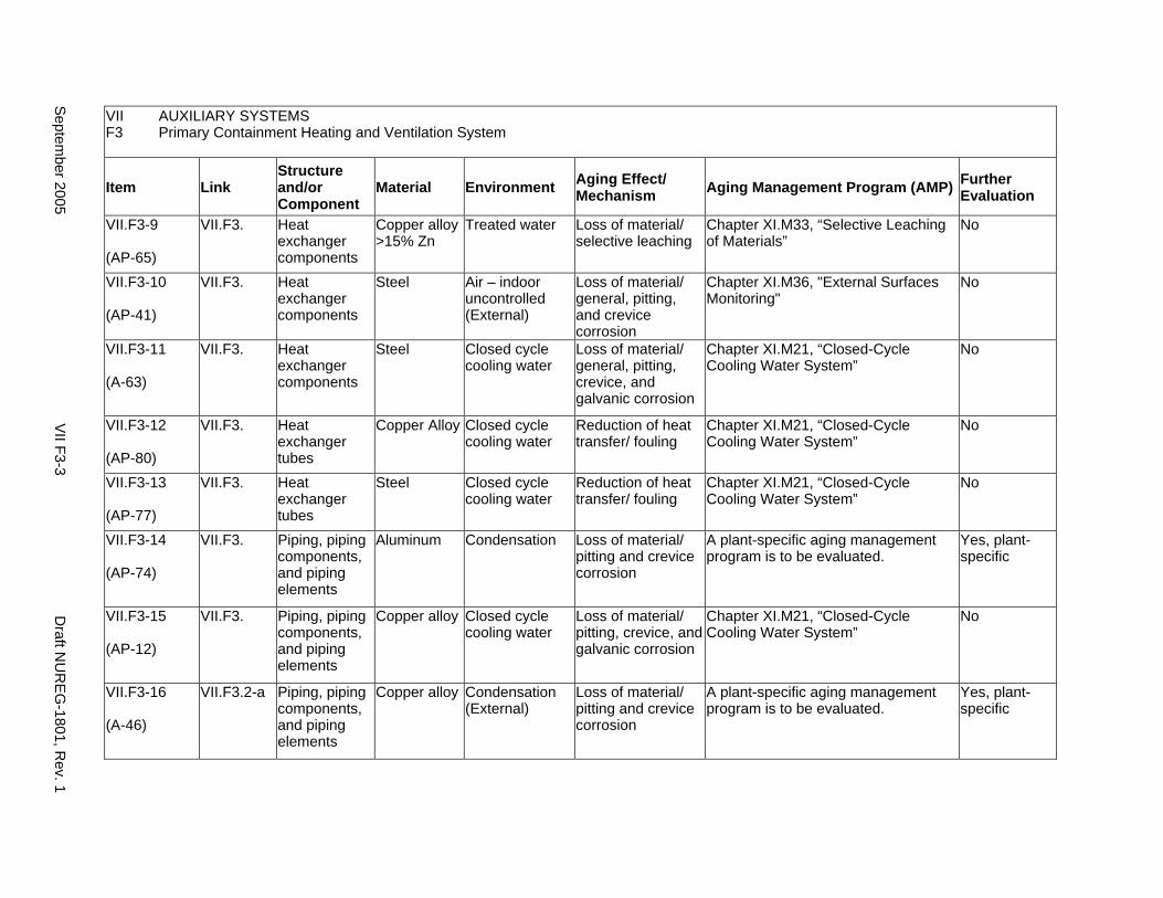
VII AUXILIARY SYSTEMS F3 Primary Containment Heating and Ventilation System
Item Link Structure and/or Component
Material Environment Aging Effect/ Mechanism Aging Management Program (AMP) Further
Evaluation
VII.F3-9
(AP-65)
VII.F3. Heat exchanger components
Copper alloy >15% Zn
Treated water Loss of material/ selective leaching
Chapter XI.M33, “Selective Leaching of Materials”
No
VII.F3-10
(AP-41)
VII.F3. Heat exchanger components
Steel Air – indoor uncontrolled (External)
Loss of material/ general, pitting, and crevice corrosion
Chapter XI.M36, "External Surfaces Monitoring"
No
VII.F3-11
(A-63)
VII.F3. Heat exchanger components
Steel Closed cycle cooling water
Loss of material/ general, pitting, crevice, and galvanic corrosion
Chapter XI.M21, “Closed-Cycle Cooling Water System”
No
VII.F3-12
(AP-80)
VII.F3. Heat exchanger tubes
Copper Alloy Closed cycle cooling water
Reduction of heat transfer/ fouling
Chapter XI.M21, “Closed-Cycle Cooling Water System”
No
VII.F3-13
(AP-77)
VII.F3. Heat exchanger tubes
Steel Closed cycle cooling water
Reduction of heat transfer/ fouling
Chapter XI.M21, “Closed-Cycle Cooling Water System”
No
VII.F3-14
(AP-74)
VII.F3. Piping, piping components, and piping elements
Aluminum Condensation Loss of material/ pitting and crevice corrosion
A plant-specific aging management program is to be evaluated.
Yes, plant-specific
VII.F3-15
(AP-12)
VII.F3. Piping, piping components, and piping elements
Copper alloy Closed cycle cooling water
Loss of material/ pitting, crevice, and galvanic corrosion
Chapter XI.M21, “Closed-Cycle Cooling Water System”
No
VII.F3-16
(A-46)
VII.F3.2-a Piping, piping components, and piping elements
Copper alloy Condensation (External)
Loss of material/ pitting and crevice corrosion
A plant-specific aging management program is to be evaluated.
Yes, plant-specific
Septem
ber 2005 V
II F3-3 D
raft NU
RE
G-1801, R
ev. 1
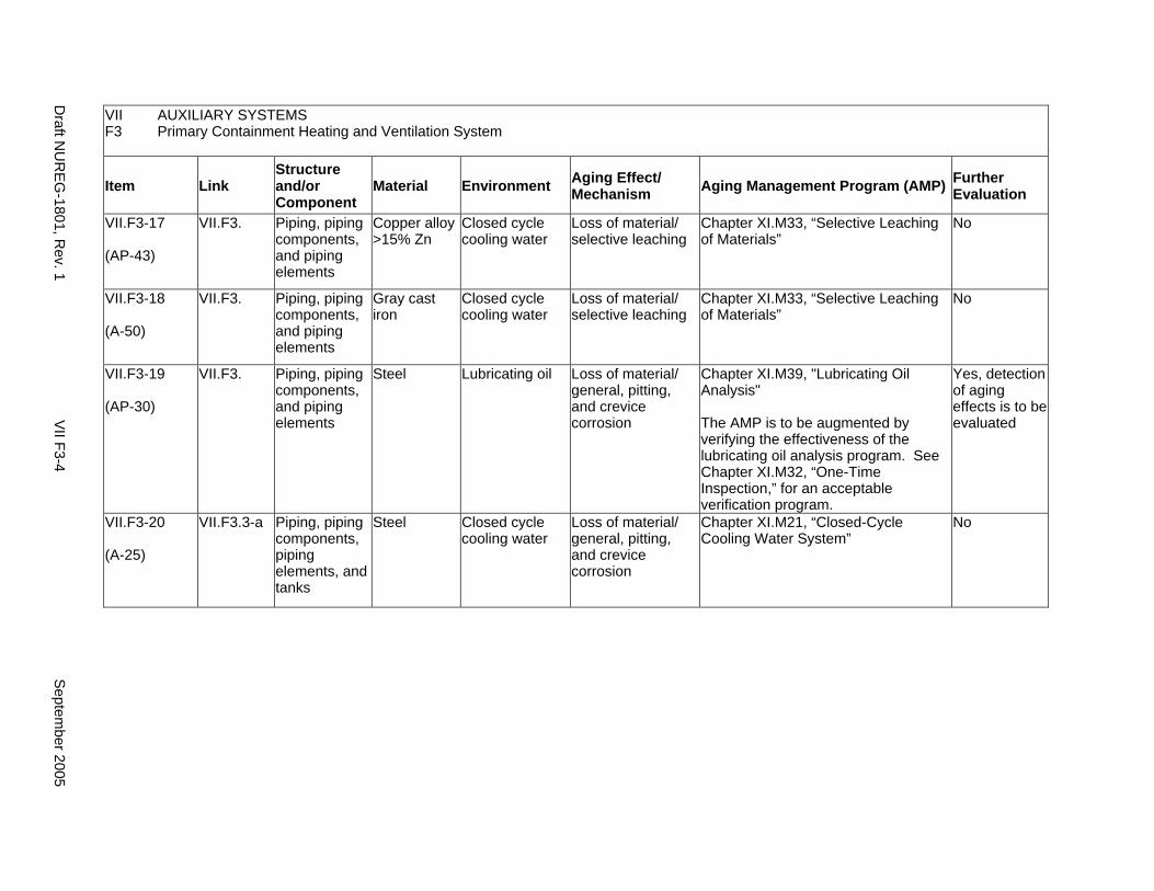
VII AUXILIARY SYSTEMS F3 Primary Containment Heating and Ventilation System
Item Link Structure and/or Component
Material Environment Aging Effect/ Mechanism Aging Management Program (AMP) Further
Evaluation
VII.F3-17
(AP-43)
VII.F3. Piping, piping components, and piping elements
Copper alloy >15% Zn
Closed cycle cooling water
Loss of material/ selective leaching
Chapter XI.M33, “Selective Leaching of Materials”
No
VII.F3-18
(A-50)
VII.F3. Piping, piping components, and piping elements
Gray cast iron
Closed cycle cooling water
Loss of material/ selective leaching
Chapter XI.M33, “Selective Leaching of Materials”
No
VII.F3-19
(AP-30)
VII.F3. Piping, piping components, and piping elements
Steel Lubricating oil Loss of material/ general, pitting, and crevice corrosion
Chapter XI.M39, "Lubricating Oil Analysis"
The AMP is to be augmented by verifying the effectiveness of the lubricating oil analysis program. See Chapter XI.M32, “One-Time Inspection,” for an acceptable verification program.
Yes, detection of aging effects is to be evaluated
VII.F3-20
(A-25)
VII.F3.3-a Piping, piping components, piping elements, and tanks
Steel Closed cycle cooling water
Loss of material/ general, pitting, and crevice corrosion
Chapter XI.M21, “Closed-Cycle Cooling Water System”
No
Draft N
UR
EG
-1801, Rev. 1
VII F3-4
Septem
ber 2005
F4. DIESEL GENERATOR BUILDING VENTILATION SYSTEM
Systems, Structures, and Components
This section discusses the diesel generator building ventilation system (with warm moist air as the normal environment), which contains ducts, piping and fittings, equipment frames and housings, flexible collars and seals, and heating and cooling air handlers. Based on Regulatory Guide 1.26, “Quality Group Classifications and Standards for Water-, Steam-, and Radioactive-Waste-Containing Components of Nuclear Power Plants,” all components that comprise the diesel generator building ventilation system are governed by Group C Quality Standards.
With respect to seals, these items are to be addressed consistent with the Nuclear Regulatory Commission (NRC) position on consumables, provided in the NRC letter from Christopher I. Grimes to Douglas J. Walters of Nuclear Energy Institute (NEI), dated March 10, 2000. Specifically, components that function as system seals are typically replaced based on performance or condition monitoring that identifies whether these components are at the end of their qualified lives and may be excluded, on a plant-specific basis, from an aging management review under 10 CFR 54.21(a)(1)(ii). As part of the methodology description, the application should identify the standards that are relied on for replacement, for example, National Fire Protection Association (NFPA) standards for fire protection equipment.
Aging management programs for the degradation of external surfaces of components and miscellaneous bolting are included in VII.I. Common miscellaneous material/environment combinations where aging effects are not expected to degrade the ability of the structure or component to perform its intended function for the extended period of operation are included in VII.J.
The system piping includes all pipe sizes, including instrument piping.
System Interfaces
The system that interfaces with the diesel generator building system is the auxiliary and radwaste area ventilation system (VII.F2). The cooling coils receive their cooling water from other systems, such as the hot water heating system or the chilled water cooling system.
September 2005 VII F4-1 Draft NUREG-1801, Rev. 1

VII AUXILIARY SYSTEMS F4 Diesel Generator Building Ventilation System
Item Link Structure and/or Component
Material Environment Aging Effect/ Mechanism Aging Management Program (AMP) Further
Evaluation
VII.F4-1
(A-10)
VII.F4.1-a Ducting and components external surfaces
Steel Air – indoor uncontrolled (External)
Loss of material/ general corrosion
Chapter XI.M36, "External Surfaces Monitoring"
No
VII.F4-2
(A-08)
VII.F4.1-a Ducting and components internal surfaces
Steel Condensation (Internal)
Loss of material/ general, pitting, crevice, and (for drip pans and drain lines) microbiologically influenced corrosion
Chapter XI.M38, "Inspection of Internal Surfaces in Miscellaneous Piping and Ducting Components"
No
VII.F4-3
(A-105)
VII.F4.1-a Ducting closure bolting
Steel Air – indoor uncontrolled (External)
Loss of material/ general corrosion
Chapter XI.M36, "External Surfaces Monitoring"
No
VII.F4-4
(A-73)
VII.F4.1-c Elastomer seals and components
Elastomers Air – indoor uncontrolled (External)
Loss of material/ wear
A plant-specific aging management program is to be evaluated.
Yes, plant-specific
VII.F4-5
(A-18)
VII.F4.1-c Elastomer seals and components
Elastomers Air – indoor uncontrolled (Internal)
Loss of material/ wear
A plant-specific aging management program is to be evaluated.
Yes, plant-specific
VII.F4-6
(A-17)
VII.F4.1-b Elastomer seals and components
Elastomers Air – indoor uncontrolled (Internal/ External)
Hardening and loss of strength/ elastomer degradation
A plant-specific aging management program is to be evaluated.
Yes, plant-specific
VII.F4-7
(AP-41)
VII.F4. Heat exchanger components
Steel Air – indoor uncontrolled (External)
Loss of material/ general, pitting, and crevice corrosion
Chapter XI.M36, "External Surfaces Monitoring"
No
Draft N
UR
EG
-1801, Rev. 1
VII F4-2
Septem
ber 2005
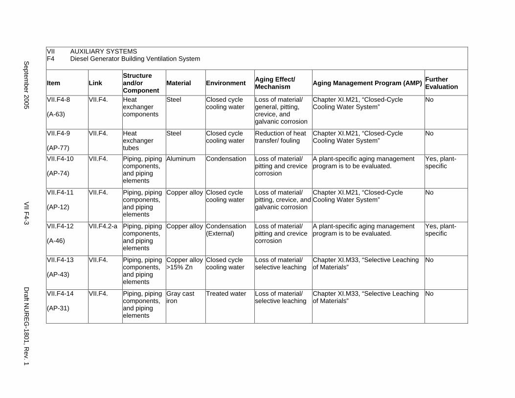
VII AUXILIARY SYSTEMS F4 Diesel Generator Building Ventilation System
Item Link Structure and/or Component
Material Environment Aging Effect/ Mechanism Aging Management Program (AMP) Further
Evaluation
VII.F4-8
(A-63)
VII.F4. Heat exchanger components
Steel Closed cycle cooling water
Loss of material/ general, pitting, crevice, and galvanic corrosion
Chapter XI.M21, “Closed-Cycle Cooling Water System”
No
VII.F4-9
(AP-77)
VII.F4. Heat exchanger tubes
Steel Closed cycle cooling water
Reduction of heat transfer/ fouling
Chapter XI.M21, “Closed-Cycle Cooling Water System”
No
VII.F4-10
(AP-74)
VII.F4. Piping, piping components, and piping elements
Aluminum Condensation Loss of material/ pitting and crevice corrosion
A plant-specific aging management program is to be evaluated.
Yes, plant-specific
VII.F4-11
(AP-12)
VII.F4. Piping, piping components, and piping elements
Copper alloy Closed cycle cooling water
Loss of material/ pitting, crevice, and galvanic corrosion
Chapter XI.M21, “Closed-Cycle Cooling Water System”
No
VII.F4-12
(A-46)
VII.F4.2-a Piping, piping components, and piping elements
Copper alloy Condensation (External)
Loss of material/ pitting and crevice corrosion
A plant-specific aging management program is to be evaluated.
Yes, plant-specific
VII.F4-13
(AP-43)
VII.F4. Piping, piping components, and piping elements
Copper alloy >15% Zn
Closed cycle cooling water
Loss of material/ selective leaching
Chapter XI.M33, “Selective Leaching of Materials”
No
VII.F4-14
(AP-31)
VII.F4. Piping, piping components, and piping elements
Gray cast iron
Treated water Loss of material/ selective leaching
Chapter XI.M33, “Selective Leaching of Materials”
No
Septem
ber 2005 V
II F4-3 D
raft NU
RE
G-1801, R
ev. 1
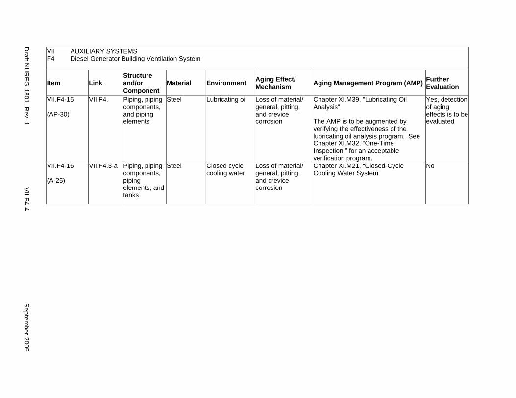
VII AUXILIARY SYSTEMS F4 Diesel Generator Building Ventilation System
Item Link Structure and/or Component
Material Environment Aging Effect/ Mechanism Aging Management Program (AMP) Further
Evaluation
VII.F4-15
(AP-30)
VII.F4. Piping, piping components, and piping elements
Steel Lubricating oil Loss of material/ general, pitting, and crevice corrosion
Chapter XI.M39, "Lubricating Oil Analysis"
The AMP is to be augmented by verifying the effectiveness of the lubricating oil analysis program. See Chapter XI.M32, “One-Time Inspection,” for an acceptable verification program.
Yes, detection of aging effects is to be evaluated
VII.F4-16
(A-25)
VII.F4.3-a Piping, piping components, piping elements, and tanks
Steel Closed cycle cooling water
Loss of material/ general, pitting, and crevice corrosion
Chapter XI.M21, “Closed-Cycle Cooling Water System”
No
Draft N
UR
EG
-1801, Rev. 1
VII F4-4
Septem
ber 2005
G. FIRE PROTECTION
Systems, Structures, and Components
This section discusses the fire protection systems for both boiling water reactors (BWRs) and pressurized water reactors (PWRs), which consist of several Class 1 structures, mechanical systems, and electrical components. The Class 1 structures include the intake structure, the turbine building, the auxiliary building, the diesel generator building, and the primary containment. Structural components include fire barrier walls, ceilings, floors, fire doors, and penetration seals. Mechanical systems include the high pressure service water system, the reactor coolant pump oil collect system, and the diesel fire system. Mechanical components include piping and fittings, filters, fire hydrants, mulsifiers, pumps, sprinklers, strainers, and valves (including containment isolation valves). Based on Regulatory Guide 1.26, “Quality Group Classifications and Standards for Water-, Steam-, and Radioactive-Waste-Containing Components of Nuclear Power Plants,” all components that comprise the fire protection system are governed by Group C Quality Standards.
With respect to filters, seals, portable fire extinguishers, and fire hoses, these items are to be addressed consistent with the NRC position on consumables, provided in the NRC letter from Christopher I. Grimes to Douglas J. Walters of Nuclear Energy Institute (NEI), dated March 10, 2000. Specifically, components that function as system filters, seals, portable fire extinguishers, and fire hoses are typically replaced based on performance or condition monitoring that identifies whether these components are at the end of their qualified lives and may be excluded, on a plant-specific basis, from an aging management review under 10 CFR 54.21(a)(1)(ii). As part of the methodology description, the application should identify the standards that are relied on for replacement, for example, National Fire Protection Association (NFPA) standards for fire protection equipment.
Pump and valve internals perform their intended functions with moving parts or with a change in configuration. They are also subject to replacement based on qualified life or specified time period. Pursuant to 10 CFR 54.21(a)(1), therefore, they are not subject to an aging management review.
Aging management programs for the degradation of external surfaces of components and miscellaneous bolting are included in VII.I. Common miscellaneous material/environment combinations where aging effects are not expected to degrade the ability of the structure or component to perform its intended function for the extended period of operation are included in VII.J.
The system piping includes all pipe sizes, including instrument piping.
System Interfaces
The systems and structures that interface with the fire protection system include various Class 1 structures and component supports (III.A and III.B), the electrical components (VI.A and VI.B), the closed-cycle cooling water system (VII.C2), and the diesel fuel oil system (VII.H1).
September 2005 VII G-1 Draft NUREG-1801, Rev. 1
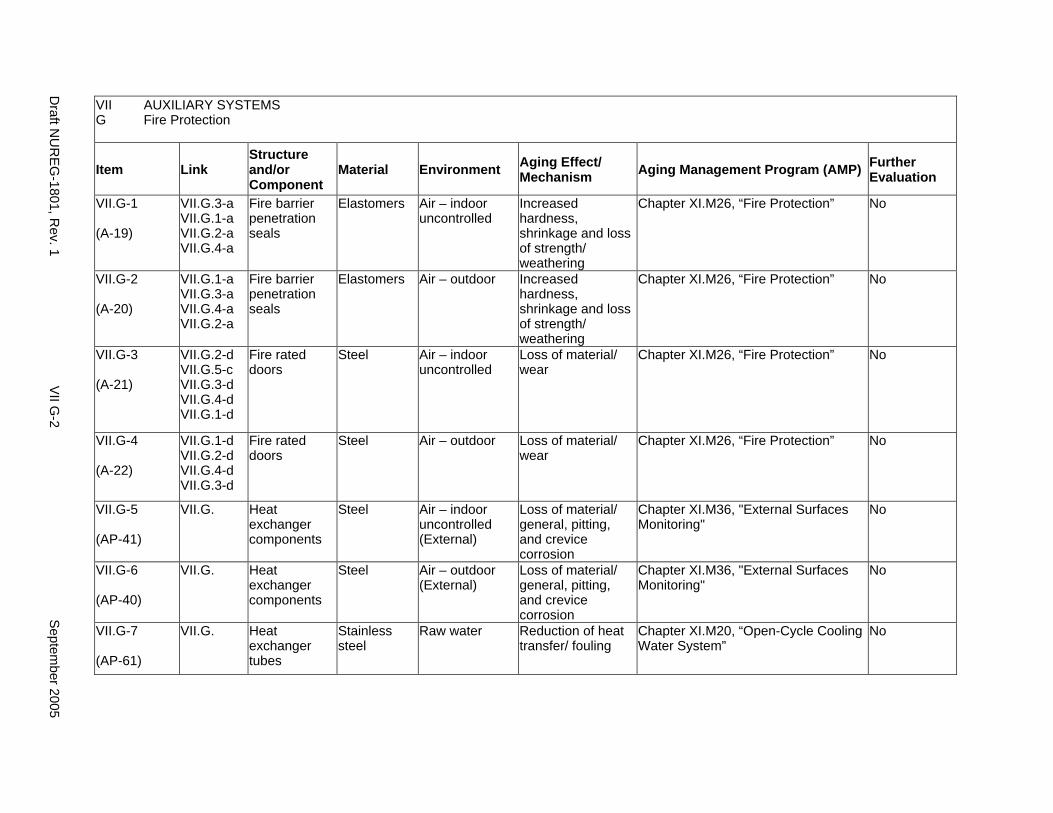
VII AUXILIARY SYSTEMS G Fire Protection
Item Link Structure and/or Component
Material Environment Aging Effect/ Mechanism Aging Management Program (AMP) Further
Evaluation
VII.G-1
(A-19)
VII.G.3-a VII.G.1-a VII.G.2-a VII.G.4-a
Fire barrier penetration seals
Elastomers Air – indoor uncontrolled
Increased hardness, shrinkage and loss of strength/ weathering
Chapter XI.M26, “Fire Protection” No
VII.G-2
(A-20)
VII.G.1-a VII.G.3-a VII.G.4-a VII.G.2-a
Fire barrier penetration seals
Elastomers Air – outdoor Increased hardness, shrinkage and loss of strength/ weathering
Chapter XI.M26, “Fire Protection” No
VII.G-3
(A-21)
VII.G.2-d VII.G.5-c VII.G.3-d VII.G.4-d VII.G.1-d
Fire rated doors
Steel Air – indoor uncontrolled
Loss of material/ wear
Chapter XI.M26, “Fire Protection” No
VII.G-4
(A-22)
VII.G.1-d VII.G.2-d VII.G.4-d VII.G.3-d
Fire rated doors
Steel Air – outdoor Loss of material/ wear
Chapter XI.M26, “Fire Protection” No
VII.G-5
(AP-41)
VII.G. Heat exchanger components
Steel Air – indoor uncontrolled (External)
Loss of material/ general, pitting, and crevice corrosion
Chapter XI.M36, "External Surfaces Monitoring"
No
VII.G-6
(AP-40)
VII.G. Heat exchanger components
Steel Air – outdoor (External)
Loss of material/ general, pitting, and crevice corrosion
Chapter XI.M36, "External Surfaces Monitoring"
No
VII.G-7
(AP-61)
VII.G. Heat exchanger tubes
Stainless steel
Raw water Reduction of heat transfer/ fouling
Chapter XI.M20, “Open-Cycle Cooling Water System”
No
Draft N
UR
EG
-1801, Rev. 1
VII G
-2 S
eptember 2005
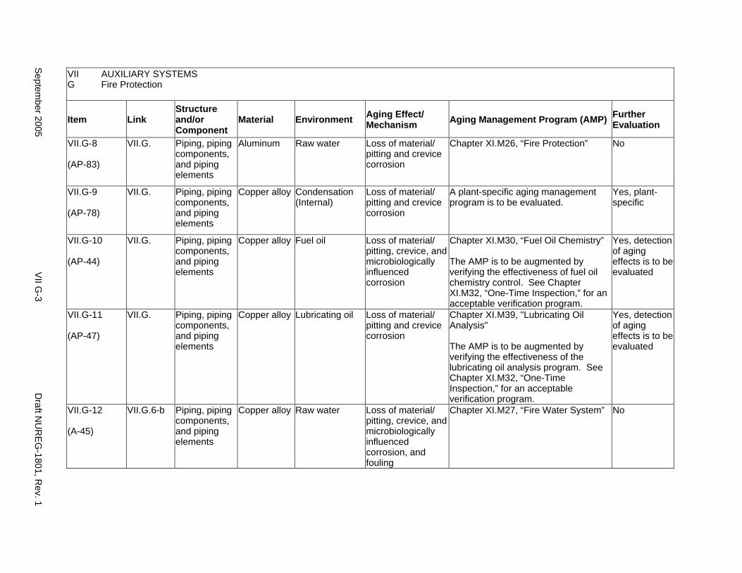
VII AUXILIARY SYSTEMS G Fire Protection
Item Link Structure and/or Component
Material Environment Aging Effect/ Mechanism Aging Management Program (AMP) Further
Evaluation
VII.G-8
(AP-83)
VII.G. Piping, piping components, and piping elements
Aluminum Raw water Loss of material/ pitting and crevice corrosion
Chapter XI.M26, “Fire Protection” No
VII.G-9
(AP-78)
VII.G. Piping, piping components, and piping elements
Copper alloy Condensation (Internal)
Loss of material/ pitting and crevice corrosion
A plant-specific aging management program is to be evaluated.
Yes, plant-specific
VII.G-10
(AP-44)
VII.G. Piping, piping components, and piping elements
Copper alloy Fuel oil Loss of material/ pitting, crevice, and microbiologically influenced corrosion
Chapter XI.M30, “Fuel Oil Chemistry”
The AMP is to be augmented by verifying the effectiveness of fuel oil chemistry control. See Chapter XI.M32, “One-Time Inspection,” for an acceptable verification program.
Yes, detection of aging effects is to be evaluated
VII.G-11
(AP-47)
VII.G. Piping, piping components, and piping elements
Copper alloy Lubricating oil Loss of material/ pitting and crevice corrosion
Chapter XI.M39, "Lubricating Oil Analysis"
The AMP is to be augmented by verifying the effectiveness of the lubricating oil analysis program. See Chapter XI.M32, “One-Time Inspection,” for an acceptable verification program.
Yes, detection of aging effects is to be evaluated
VII.G-12
(A-45)
VII.G.6-b Piping, piping components, and piping elements
Copper alloy Raw water Loss of material/ pitting, crevice, and microbiologically influenced corrosion, and fouling
Chapter XI.M27, “Fire Water System” No
Septem
ber 2005 V
II G-3
Draft N
UR
EG
-1801, Rev. 1
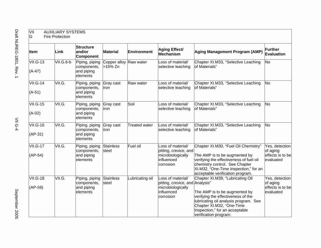
VII AUXILIARY SYSTEMS G Fire Protection
Item Link Structure and/or Component
Material Environment Aging Effect/ Mechanism Aging Management Program (AMP) Further
Evaluation
VII.G-13
(A-47)
VII.G.6-b Piping, piping components, and piping elements
Copper alloy >15% Zn
Raw water Loss of material/ selective leaching
Chapter XI.M33, “Selective Leaching of Materials”
No
VII.G-14
(A-51)
VII.G. Piping, piping components, and piping elements
Gray cast iron
Raw water Loss of material/ selective leaching
Chapter XI.M33, “Selective Leaching of Materials”
No
VII.G-15
(A-02)
VII.G. Piping, piping components, and piping elements
Gray cast iron
Soil Loss of material/ selective leaching
Chapter XI.M33, “Selective Leaching of Materials"
No
VII.G-16
(AP-31)
VII.G. Piping, piping components, and piping elements
Gray cast iron
Treated water Loss of material/ selective leaching
Chapter XI.M33, “Selective Leaching of Materials”
No
VII.G-17
(AP-54)
VII.G. Piping, piping components, and piping elements
Stainless steel
Fuel oil Loss of material/ pitting, crevice, and microbiologically influenced corrosion
Chapter XI.M30, “Fuel Oil Chemistry”
The AMP is to be augmented by verifying the effectiveness of fuel oil chemistry control. See Chapter XI.M32, “One-Time Inspection,” for an acceptable verification program.
Yes, detection of aging effects is to be evaluated
VII.G-18
(AP-59)
VII.G. Piping, piping components, and piping elements
Stainless steel
Lubricating oil Loss of material/ pitting, crevice, and microbiologically influenced corrosion
Chapter XI.M39, "Lubricating Oil Analysis"
The AMP is to be augmented by verifying the effectiveness of the lubricating oil analysis program. See Chapter XI.M32, “One-Time Inspection,” for an acceptable verification program.
Yes, detection of aging effects is to be evaluated
Draft N
UR
EG
-1801, Rev. 1
VII G
-4 S
eptember 2005
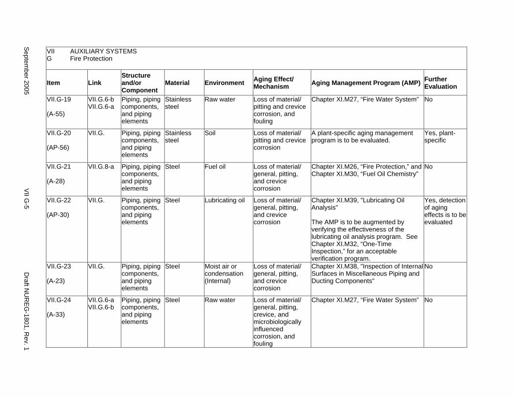
VII AUXILIARY SYSTEMS G Fire Protection
Item Link Structure and/or Component
Material Environment Aging Effect/ Mechanism Aging Management Program (AMP) Further
Evaluation
VII.G-19
(A-55)
VII.G.6-b VII.G.6-a
Piping, piping components, and piping elements
Stainless steel
Raw water Loss of material/ pitting and crevice corrosion, and fouling
Chapter XI.M27, “Fire Water System” No
VII.G-20
(AP-56)
VII.G. Piping, piping components, and piping elements
Stainless steel
Soil Loss of material/ pitting and crevice corrosion
A plant-specific aging management program is to be evaluated.
Yes, plant-specific
VII.G-21
(A-28)
VII.G.8-a Piping, piping components, and piping elements
Steel Fuel oil Loss of material/ general, pitting, and crevice corrosion
Chapter XI.M26, “Fire Protection,” and Chapter XI.M30, “Fuel Oil Chemistry”
No
VII.G-22
(AP-30)
VII.G. Piping, piping components, and piping elements
Steel Lubricating oil Loss of material/ general, pitting, and crevice corrosion
Chapter XI.M39, "Lubricating Oil Analysis"
The AMP is to be augmented by verifying the effectiveness of the lubricating oil analysis program. See Chapter XI.M32, “One-Time Inspection,” for an acceptable verification program.
Yes, detection of aging effects is to be evaluated
VII.G-23
(A-23)
VII.G. Piping, piping components, and piping elements
Steel Moist air or condensation (Internal)
Loss of material/ general, pitting, and crevice corrosion
Chapter XI.M38, "Inspection of Internal Surfaces in Miscellaneous Piping and Ducting Components"
No
VII.G-24
(A-33)
VII.G.6-a VII.G.6-b
Piping, piping components, and piping elements
Steel Raw water Loss of material/ general, pitting, crevice, and microbiologically influenced corrosion, and fouling
Chapter XI.M27, “Fire Water System” No
Septem
ber 2005 V
II G-5
Draft N
UR
EG
-1801, Rev. 1
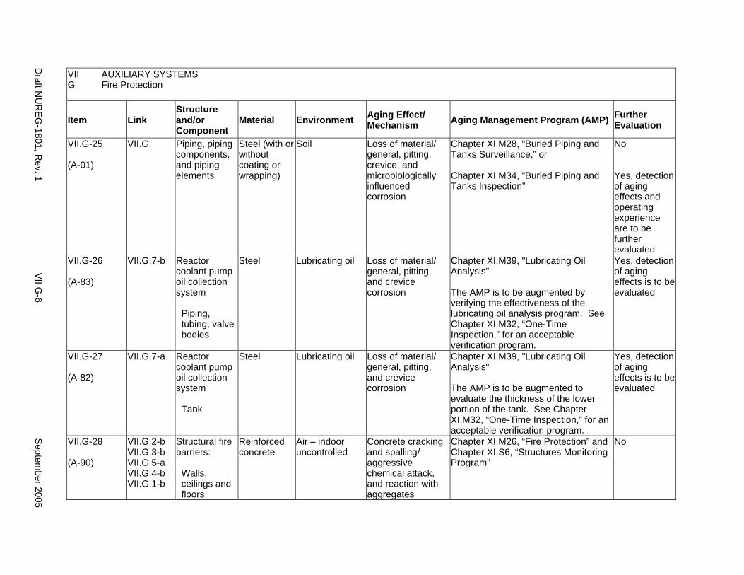
VII AUXILIARY SYSTEMS G Fire Protection
Item Link Structure and/or Component
Material Environment Aging Effect/ Mechanism Aging Management Program (AMP) Further
Evaluation
VII.G-25
(A-01)
VII.G. Piping, piping components, and piping elements
Steel (with or without coating or wrapping)
Soil Loss of material/ general, pitting, crevice, and microbiologically influenced corrosion
Chapter XI.M28, “Buried Piping and Tanks Surveillance,” or
Chapter XI.M34, “Buried Piping and Tanks Inspection”
No
Yes, detection of aging effects and operating experience are to be further evaluated
VII.G-26
(A-83)
VII.G.7-b Reactor coolant pump oil collection system
Piping, tubing, valve bodies
Steel Lubricating oil Loss of material/ general, pitting, and crevice corrosion
Chapter XI.M39, "Lubricating Oil Analysis"
The AMP is to be augmented by verifying the effectiveness of the lubricating oil analysis program. See Chapter XI.M32, “One-Time Inspection,” for an acceptable verification program.
Yes, detection of aging effects is to be evaluated
VII.G-27
(A-82)
VII.G.7-a Reactor coolant pump oil collection system
Tank
Steel Lubricating oil Loss of material/ general, pitting, and crevice corrosion
Chapter XI.M39, "Lubricating Oil Analysis"
The AMP is to be augmented to evaluate the thickness of the lower portion of the tank. See Chapter XI.M32, “One-Time Inspection,” for an acceptable verification program.
Yes, detection of aging effects is to be evaluated
VII.G-28
(A-90)
VII.G.2-b VII.G.3-b VII.G.5-a VII.G.4-b VII.G.1-b
Structural fire barriers:
Walls, ceilings and floors
Reinforced concrete
Air – indoor uncontrolled
Concrete cracking and spalling/ aggressive chemical attack, and reaction with aggregates
Chapter XI.M26, “Fire Protection” and Chapter XI.S6, “Structures Monitoring Program”
No
Draft N
UR
EG
-1801, Rev. 1
VII G
-6 S
eptember 2005
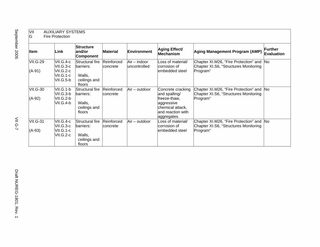
VII AUXILIARY SYSTEMS G Fire Protection
Item Link Structure and/or Component
Material Environment Aging Effect/ Mechanism Aging Management Program (AMP) Further
Evaluation
VII.G-29
(A-91)
VII.G.4-c VII.G.3-c VII.G.2-c VII.G.1-c VII.G.5-b
Structural fire barriers:
Walls, ceilings and floors
Reinforced concrete
Air – indoor uncontrolled
Loss of material/ corrosion of embedded steel
Chapter XI.M26, “Fire Protection” and Chapter XI.S6, “Structures Monitoring Program”
No
VII.G-30
(A-92)
VII.G.1-b VII.G.3-b VII.G.2-b VII.G.4-b
Structural fire barriers:
Walls, ceilings and floors
Reinforced concrete
Air – outdoor Concrete cracking and spalling/ freeze-thaw, aggressive chemical attack, and reaction with aggregates
Chapter XI.M26, “Fire Protection” and Chapter XI.S6, “Structures Monitoring Program”
No
VII.G-31
(A-93)
VII.G.4-c VII.G.3-c VII.G.1-c VII.G.2-c
Structural fire barriers:
Walls, ceilings and floors
Reinforced concrete
Air – outdoor Loss of material/ corrosion of embedded steel
Chapter XI.M26, “Fire Protection” and Chapter XI.S6, “Structures Monitoring Program”
No
Septem
ber 2005 V
II G-7
Draft N
UR
EG
-1801, Rev. 1

This Page Intentionally Left Blank
Draft NUREG-1801, Rev. 1 VII G-8 September 2005
H1. DIESEL FUEL OIL SYSTEM
Systems, Structures, and Components
This section discusses the diesel fuel oil system, which consists of aboveground and underground piping, valves, pumps, and tanks. Based on Regulatory Guide 1.26, “Quality Group Classifications and Standards for Water-, Steam-, and Radioactive-Waste-Containing Components of Nuclear Power Plants,” all components that comprise the diesel fuel oil system are governed by Group C Quality Standards.
Aging management programs for the degradation of external surfaces of components and miscellaneous bolting are included in VII.I. Common miscellaneous material/environment combinations where aging effects are not expected to degrade the ability of the structure or component to perform its intended function for the extended period of operation are included in VII.J.
The system piping includes all pipe sizes, including instrument piping.
System Interfaces
The systems that interface with the diesel fuel oil system are the fire protection (VII.G) and emergency diesel generator systems (VII.H2).
September 2005 VII H1-1 Draft NUREG-1801, Rev. 1
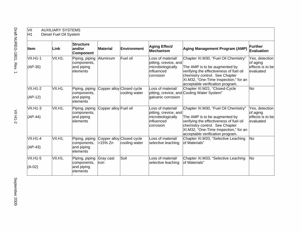
VII AUXILIARY SYSTEMS H1 Diesel Fuel Oil System
Item Link Structure and/or Component
Material Environment Aging Effect/ Mechanism Aging Management Program (AMP) Further
Evaluation
VII.H1-1
(AP-35)
VII.H1. Piping, piping components, and piping elements
Aluminum Fuel oil Loss of material/ pitting, crevice, and microbiologically influenced corrosion
Chapter XI.M30, “Fuel Oil Chemistry”
The AMP is to be augmented by verifying the effectiveness of fuel oil chemistry control. See Chapter XI.M32, “One-Time Inspection,” for an acceptable verification program.
Yes, detection of aging effects is to be evaluated
VII.H1-2
(AP-12)
VII.H1. Piping, piping components, and piping elements
Copper alloy Closed cycle cooling water
Loss of material/ pitting, crevice, and galvanic corrosion
Chapter XI.M21, “Closed-Cycle Cooling Water System”
No
VII.H1-3
(AP-44)
VII.H1. Piping, piping components, and piping elements
Copper alloy Fuel oil Loss of material/ pitting, crevice, and microbiologically influenced corrosion
Chapter XI.M30, “Fuel Oil Chemistry”
The AMP is to be augmented by verifying the effectiveness of fuel oil chemistry control. See Chapter XI.M32, “One-Time Inspection,” for an acceptable verification program.
Yes, detection of aging effects is to be evaluated
VII.H1-4
(AP-43)
VII.H1. Piping, piping components, and piping elements
Copper alloy >15% Zn
Closed cycle cooling water
Loss of material/ selective leaching
Chapter XI.M33, “Selective Leaching of Materials”
No
VII.H1-5
(A-02)
VII.H1. Piping, piping components, and piping elements
Gray cast iron
Soil Loss of material/ selective leaching
Chapter XI.M33, “Selective Leaching of Materials"
No
Draft N
UR
EG
-1801, Rev. 1
VII H
1-2 S
eptember 2005
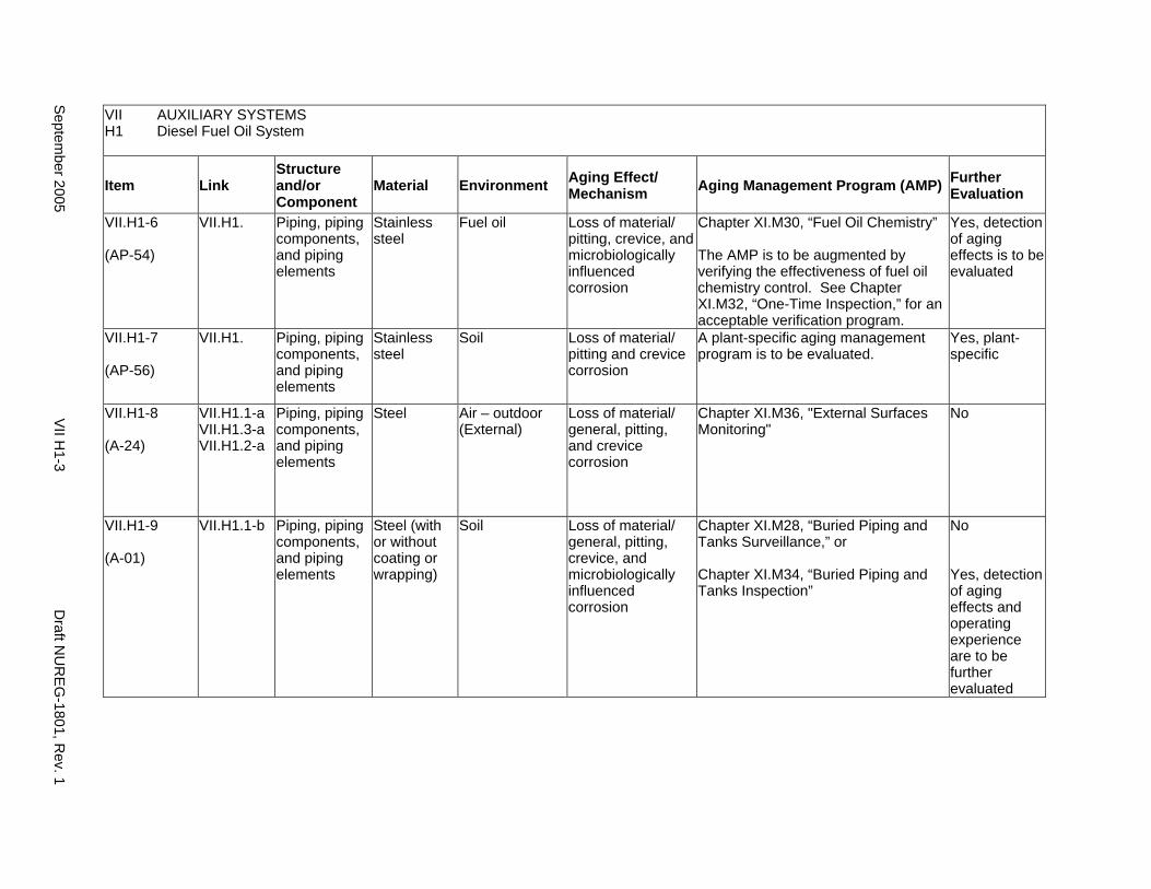
VII AUXILIARY SYSTEMS H1 Diesel Fuel Oil System
Item Link Structure and/or Component
Material Environment Aging Effect/ Mechanism Aging Management Program (AMP) Further
Evaluation
VII.H1-6
(AP-54)
VII.H1. Piping, piping components, and piping elements
Stainless steel
Fuel oil Loss of material/ pitting, crevice, and microbiologically influenced corrosion
Chapter XI.M30, “Fuel Oil Chemistry”
The AMP is to be augmented by verifying the effectiveness of fuel oil chemistry control. See Chapter XI.M32, “One-Time Inspection,” for an acceptable verification program.
Yes, detection of aging effects is to be evaluated
VII.H1-7
(AP-56)
VII.H1. Piping, piping components, and piping elements
Stainless steel
Soil Loss of material/ pitting and crevice corrosion
A plant-specific aging management program is to be evaluated.
Yes, plant-specific
VII.H1-8
(A-24)
VII.H1.1-a VII.H1.3-a VII.H1.2-a
Piping, piping components, and piping elements
Steel Air – outdoor (External)
Loss of material/ general, pitting, and crevice corrosion
Chapter XI.M36, "External Surfaces Monitoring"
No
VII.H1-9
(A-01)
VII.H1.1-b Piping, piping components, and piping elements
Steel (with or without coating or wrapping)
Soil Loss of material/ general, pitting, crevice, and microbiologically influenced corrosion
Chapter XI.M28, “Buried Piping and Tanks Surveillance,” or
Chapter XI.M34, “Buried Piping and Tanks Inspection”
No
Yes, detection of aging effects and operating experience are to be further evaluated
Septem
ber 2005 V
II H1-3
Draft N
UR
EG
-1801, Rev. 1
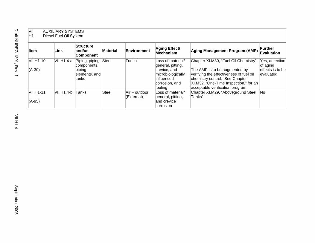
VII AUXILIARY SYSTEMS H1 Diesel Fuel Oil System
Item Link Structure and/or Component
Material Environment Aging Effect/ Mechanism Aging Management Program (AMP) Further
Evaluation
VII.H1-10
(A-30)
VII.H1.4-a Piping, piping components, piping elements, and tanks
Steel Fuel oil Loss of material/ general, pitting, crevice, and microbiologically influenced corrosion, and fouling
Chapter XI.M30, “Fuel Oil Chemistry”
The AMP is to be augmented by verifying the effectiveness of fuel oil chemistry control. See Chapter XI.M32, “One-Time Inspection,” for an acceptable verification program.
Yes, detection of aging effects is to be evaluated
VII.H1-11
(A-95)
VII.H1.4-b Tanks Steel Air – outdoor (External)
Loss of material/ general, pitting, and crevice corrosion
Chapter XI.M29, “Aboveground Steel Tanks”
No
Draft N
UR
EG
-1801, Rev. 1
VII H
1-4 S
eptember 2005

H2. EMERGENCY DIESEL GENERATOR SYSTEM
Systems, Structures, and Components
This section discusses the emergency diesel generator system, which contains piping, valves, filters, mufflers, strainers, and tanks. Based on Regulatory Guide 1.26, “Quality Group Classifications and Standards for Water-, Steam-, and Radioactive-Waste-Containing Components of Nuclear Power Plants,” all components that comprise the emergency diesel generator system are governed by Group C Quality Standards.
With respect to filters, these items are to be addressed consistent with the NRC position on consumables, provided in the NRC letter from Christopher I. Grimes to Douglas J. Walters of Nuclear Energy Institute (NEI), dated March 10, 2000. Specifically, components that function as system filters are typically replaced based on performance or condition monitoring that identifies whether these components are at the end of their qualified lives and may be excluded, on a plant-specific basis, from an aging management review under 10 CFR 54.21(a)(1)(ii). As part of the methodology description, the application should identify the standards that are relied on for replacement, for example, National Fire Protection Association (NFPA) standards for fire protection equipment.
Aging management programs for the degradation of external surfaces of components and miscellaneous bolting are included in VII.I. Common miscellaneous material/environment combinations where aging effects are not expected to degrade the ability of the structure or component to perform its intended function for the extended period of operation are included in VII.J.
The system piping includes all pipe sizes, including instrument piping.
System Interfaces
The systems that interface with the emergency diesel generator system include the diesel fuel oil system (VII.H1), the closed-cycle cooling water system (VII.C2) and the open-cycle cooling water system (VII.C1) for some plants.
September 2005 VII H2-1 Draft NUREG-1801, Rev. 1
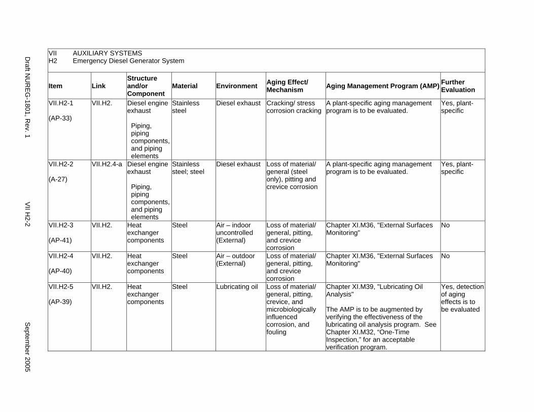
VII AUXILIARY SYSTEMS H2 Emergency Diesel Generator System
Item Link Structure and/or Component
Material Environment Aging Effect/ Mechanism Aging Management Program (AMP) Further
Evaluation
VII.H2-1
(AP-33)
VII.H2. Diesel engine exhaust
Piping, piping components, and piping elements
Stainless steel
Diesel exhaust Cracking/ stress corrosion cracking
A plant-specific aging management program is to be evaluated.
Yes, plant-specific
VII.H2-2
(A-27)
VII.H2.4-a Diesel engine exhaust
Piping, piping components, and piping elements
Stainless steel; steel
Diesel exhaust Loss of material/ general (steel only), pitting and crevice corrosion
A plant-specific aging management program is to be evaluated.
Yes, plant-specific
VII.H2-3
(AP-41)
VII.H2. Heat exchanger components
Steel Air – indoor uncontrolled (External)
Loss of material/ general, pitting, and crevice corrosion
Chapter XI.M36, "External Surfaces Monitoring"
No
VII.H2-4
(AP-40)
VII.H2. Heat exchanger components
Steel Air – outdoor (External)
Loss of material/ general, pitting, and crevice corrosion
Chapter XI.M36, "External Surfaces Monitoring"
No
VII.H2-5
(AP-39)
VII.H2. Heat exchanger components
Steel Lubricating oil Loss of material/ general, pitting, crevice, and microbiologically influenced corrosion, and fouling
Chapter XI.M39, "Lubricating Oil Analysis"
The AMP is to be augmented by verifying the effectiveness of the lubricating oil analysis program. See Chapter XI.M32, “One-Time Inspection,” for an acceptable verification program.
Yes, detection of aging effects is to be evaluated
Draft N
UR
EG
-1801, Rev. 1
VII H
2-2 S
eptember 2005
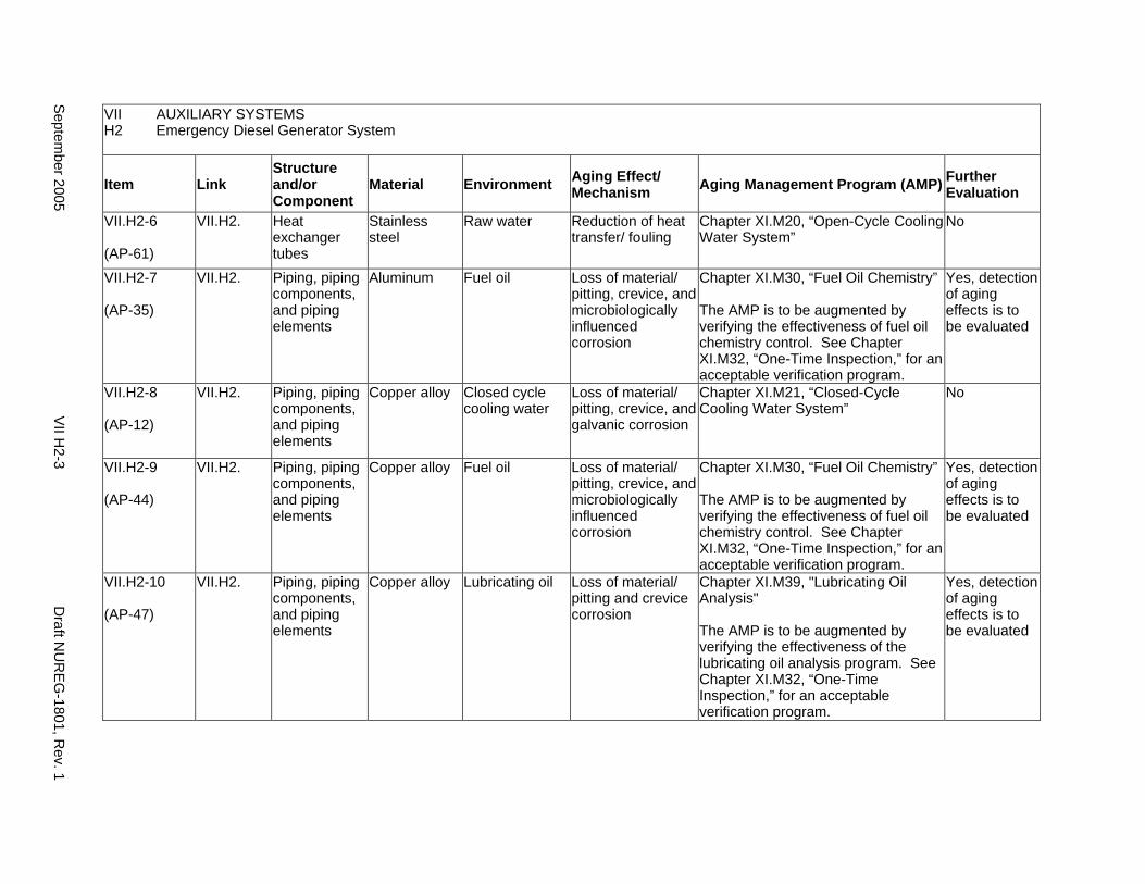
VII AUXILIARY SYSTEMS H2 Emergency Diesel Generator System
Item Link Structure and/or Component
Material Environment Aging Effect/ Mechanism Aging Management Program (AMP) Further
Evaluation
VII.H2-6
(AP-61)
VII.H2. Heat exchanger tubes
Stainless steel
Raw water Reduction of heat transfer/ fouling
Chapter XI.M20, “Open-Cycle Cooling Water System”
No
VII.H2-7
(AP-35)
VII.H2. Piping, piping components, and piping elements
Aluminum Fuel oil Loss of material/ pitting, crevice, and microbiologically influenced corrosion
Chapter XI.M30, “Fuel Oil Chemistry”
The AMP is to be augmented by verifying the effectiveness of fuel oil chemistry control. See Chapter XI.M32, “One-Time Inspection,” for an acceptable verification program.
Yes, detection of aging effects is to be evaluated
VII.H2-8
(AP-12)
VII.H2. Piping, piping components, and piping elements
Copper alloy Closed cycle cooling water
Loss of material/ pitting, crevice, and galvanic corrosion
Chapter XI.M21, “Closed-Cycle Cooling Water System”
No
VII.H2-9
(AP-44)
VII.H2. Piping, piping components, and piping elements
Copper alloy Fuel oil Loss of material/ pitting, crevice, and microbiologically influenced corrosion
Chapter XI.M30, “Fuel Oil Chemistry”
The AMP is to be augmented by verifying the effectiveness of fuel oil chemistry control. See Chapter XI.M32, “One-Time Inspection,” for an acceptable verification program.
Yes, detection of aging effects is to be evaluated
VII.H2-10
(AP-47)
VII.H2. Piping, piping components, and piping elements
Copper alloy Lubricating oil Loss of material/ pitting and crevice corrosion
Chapter XI.M39, "Lubricating Oil Analysis"
The AMP is to be augmented by verifying the effectiveness of the lubricating oil analysis program. See Chapter XI.M32, “One-Time Inspection,” for an acceptable verification program.
Yes, detection of aging effects is to be evaluated
Septem
ber 2005 V
II H2-3
Draft N
UR
EG
-1801, Rev. 1
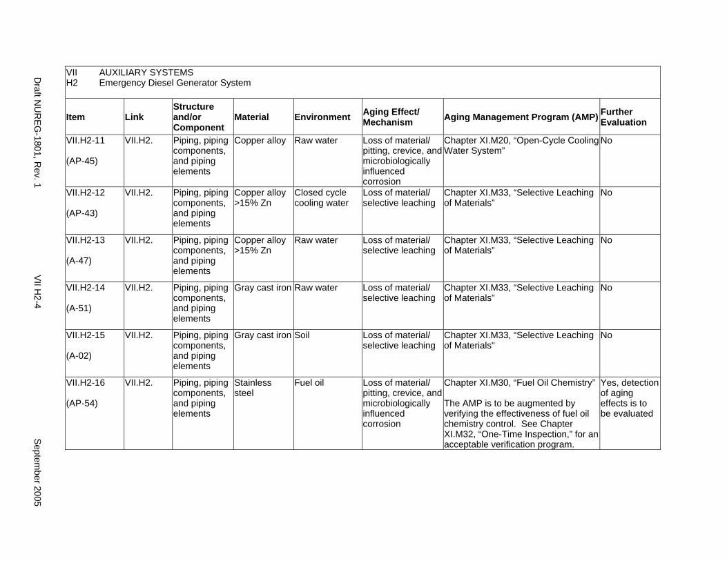
VII AUXILIARY SYSTEMS H2 Emergency Diesel Generator System
Item Link Structure and/or Component
Material Environment Aging Effect/ Mechanism Aging Management Program (AMP) Further
Evaluation
VII.H2-11
(AP-45)
VII.H2. Piping, piping components, and piping elements
Copper alloy Raw water Loss of material/ pitting, crevice, and microbiologically influenced corrosion
Chapter XI.M20, “Open-Cycle Cooling Water System”
No
VII.H2-12
(AP-43)
VII.H2. Piping, piping components, and piping elements
Copper alloy >15% Zn
Closed cycle cooling water
Loss of material/ selective leaching
Chapter XI.M33, “Selective Leaching of Materials”
No
VII.H2-13
(A-47)
VII.H2. Piping, piping components, and piping elements
Copper alloy >15% Zn
Raw water Loss of material/ selective leaching
Chapter XI.M33, “Selective Leaching of Materials”
No
VII.H2-14
(A-51)
VII.H2. Piping, piping components, and piping elements
Gray cast iron Raw water Loss of material/ selective leaching
Chapter XI.M33, “Selective Leaching of Materials”
No
VII.H2-15
(A-02)
VII.H2. Piping, piping components, and piping elements
Gray cast iron Soil Loss of material/ selective leaching
Chapter XI.M33, “Selective Leaching of Materials"
No
VII.H2-16
(AP-54)
VII.H2. Piping, piping components, and piping elements
Stainless steel
Fuel oil Loss of material/ pitting, crevice, and microbiologically influenced corrosion
Chapter XI.M30, “Fuel Oil Chemistry”
The AMP is to be augmented by verifying the effectiveness of fuel oil chemistry control. See Chapter XI.M32, “One-Time Inspection,” for an acceptable verification program.
Yes, detection of aging effects is to be evaluated
Draft N
UR
EG
-1801, Rev. 1
VII H
2-4 S
eptember 2005
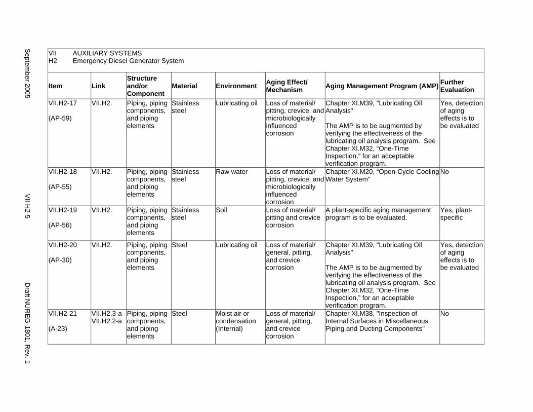
VII AUXILIARY SYSTEMS H2 Emergency Diesel Generator System
Item Link Structure and/or Component
Material Environment Aging Effect/ Mechanism Aging Management Program (AMP) Further
Evaluation
VII.H2-17
(AP-59)
VII.H2. Piping, piping components, and piping elements
Stainless steel
Lubricating oil Loss of material/ pitting, crevice, and microbiologically influenced corrosion
Chapter XI.M39, "Lubricating Oil Analysis"
The AMP is to be augmented by verifying the effectiveness of the lubricating oil analysis program. See Chapter XI.M32, “One-Time Inspection,” for an acceptable verification program.
Yes, detection of aging effects is to be evaluated
VII.H2-18
(AP-55)
VII.H2. Piping, piping components, and piping elements
Stainless steel
Raw water Loss of material/ pitting, crevice, and microbiologically influenced corrosion
Chapter XI.M20, “Open-Cycle Cooling Water System”
No
VII.H2-19
(AP-56)
VII.H2. Piping, piping components, and piping elements
Stainless steel
Soil Loss of material/ pitting and crevice corrosion
A plant-specific aging management program is to be evaluated.
Yes, plant-specific
VII.H2-20
(AP-30)
VII.H2. Piping, piping components, and piping elements
Steel Lubricating oil Loss of material/ general, pitting, and crevice corrosion
Chapter XI.M39, "Lubricating Oil Analysis"
The AMP is to be augmented by verifying the effectiveness of the lubricating oil analysis program. See Chapter XI.M32, “One-Time Inspection,” for an acceptable verification program.
Yes, detection of aging effects is to be evaluated
VII.H2-21
(A-23)
VII.H2.3-a VII.H2.2-a
Piping, piping components, and piping elements
Steel Moist air or condensation (Internal)
Loss of material/ general, pitting, and crevice corrosion
Chapter XI.M38, "Inspection of Internal Surfaces in Miscellaneous Piping and Ducting Components"
No
Septem
ber 2005 V
II H2-5
Draft N
UR
EG
-1801, Rev. 1
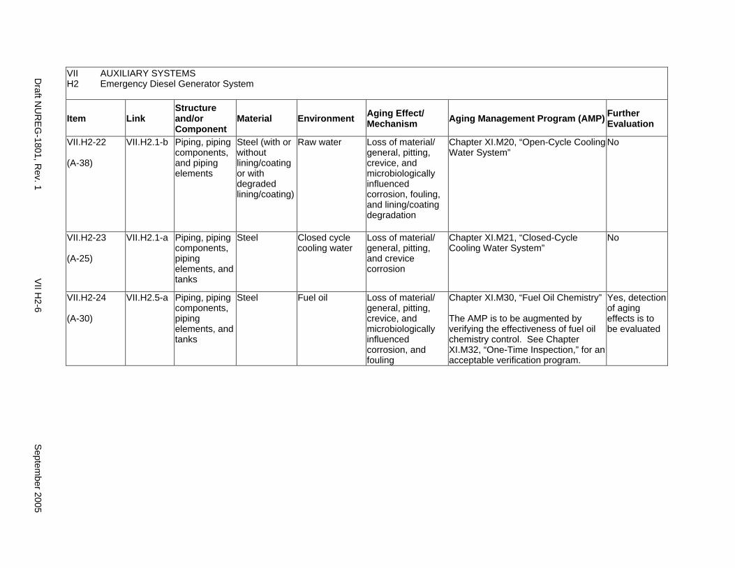
VII AUXILIARY SYSTEMS H2 Emergency Diesel Generator System
Item Link Structure and/or Component
Material Environment Aging Effect/ Mechanism Aging Management Program (AMP) Further
Evaluation
VII.H2-22
(A-38)
VII.H2.1-b Piping, piping components, and piping elements
Steel (with or without lining/coating or with degraded lining/coating)
Raw water Loss of material/ general, pitting, crevice, and microbiologically influenced corrosion, fouling, and lining/coating degradation
Chapter XI.M20, “Open-Cycle Cooling Water System”
No
VII.H2-23
(A-25)
VII.H2.1-a Piping, piping components, piping elements, and tanks
Steel Closed cycle cooling water
Loss of material/ general, pitting, and crevice corrosion
Chapter XI.M21, “Closed-Cycle Cooling Water System”
No
VII.H2-24
(A-30)
VII.H2.5-a Piping, piping components, piping elements, and tanks
Steel Fuel oil Loss of material/ general, pitting, crevice, and microbiologically influenced corrosion, and fouling
Chapter XI.M30, “Fuel Oil Chemistry”
The AMP is to be augmented by verifying the effectiveness of fuel oil chemistry control. See Chapter XI.M32, “One-Time Inspection,” for an acceptable verification program.
Yes, detection of aging effects is to be evaluated
Draft N
UR
EG
-1801, Rev. 1
VII H
2-6 S
eptember 2005

I. EXTERNAL SURFACES OF COMPONENTS AND MISCELLANEOUS BOLTING
Systems, Structures, and Components
This section addresses the aging management programs for the external surfaces of all steel structures and components including closure boltings in the Auxiliary Systems in pressurized water reactors (PWRs) and boiling water reactors (BWRs). For the steel components in PWRs, this section addresses only boric acid corrosion of external surface as a result of dripping borated water that is leaking from an adjacent PWR component. Boric acid corrosion can also occur for steel components containing borated water due to leakage; such components and the related aging management program are covered in the appropriate major plant sections in VII.
System Interfaces
The structures and components covered in this section belong to the Auxiliary Systems in PWRs and BWRs. (For example, see System Interfaces in VII.A1 to VII.H2 for details.)
September 2005 VII I-1 Draft NUREG-1801, Rev. 1
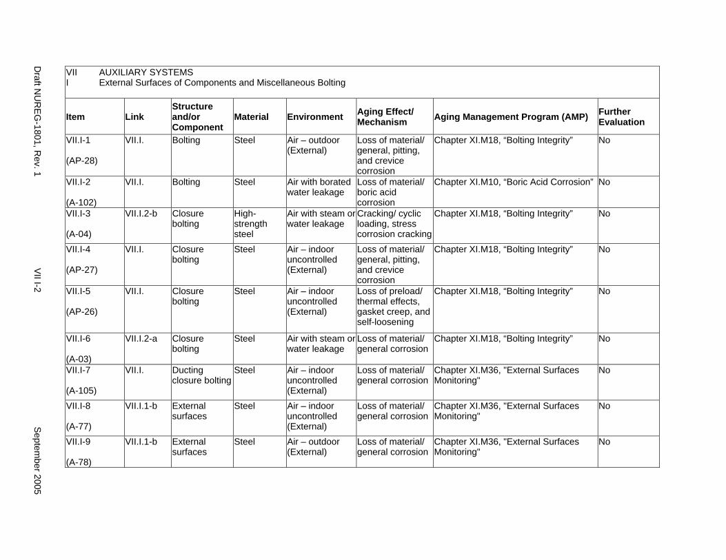
VII AUXILIARY SYSTEMS I External Surfaces of Components and Miscellaneous Bolting
Item Link Structure and/or Component
Material Environment Aging Effect/ Mechanism Aging Management Program (AMP) Further
Evaluation
VII.I-1
(AP-28)
VII.I. Bolting Steel Air – outdoor (External)
Loss of material/ general, pitting, and crevice corrosion
Chapter XI.M18, “Bolting Integrity” No
VII.I-2
(A-102)
VII.I. Bolting Steel Air with borated water leakage
Loss of material/ boric acid corrosion
Chapter XI.M10, “Boric Acid Corrosion” No
VII.I-3
(A-04)
VII.I.2-b Closure bolting
High-strength steel
Air with steam or water leakage
Cracking/ cyclic loading, stress corrosion cracking
Chapter XI.M18, “Bolting Integrity” No
VII.I-4
(AP-27)
VII.I. Closure bolting
Steel Air – indoor uncontrolled (External)
Loss of material/ general, pitting, and crevice corrosion
Chapter XI.M18, “Bolting Integrity” No
VII.I-5
(AP-26)
VII.I. Closure bolting
Steel Air – indoor uncontrolled (External)
Loss of preload/ thermal effects, gasket creep, and self-loosening
Chapter XI.M18, “Bolting Integrity” No
VII.I-6
(A-03)
VII.I.2-a Closure bolting
Steel Air with steam or water leakage
Loss of material/ general corrosion
Chapter XI.M18, “Bolting Integrity” No
VII.I-7
(A-105)
VII.I. Ducting closure bolting
Steel Air – indoor uncontrolled (External)
Loss of material/ general corrosion
Chapter XI.M36, "External Surfaces Monitoring"
No
VII.I-8
(A-77)
VII.I.1-b External surfaces
Steel Air – indoor uncontrolled (External)
Loss of material/ general corrosion
Chapter XI.M36, "External Surfaces Monitoring"
No
VII.I-9
(A-78)
VII.I.1-b External surfaces
Steel Air – outdoor (External)
Loss of material/ general corrosion
Chapter XI.M36, "External Surfaces Monitoring"
No
Draft N
UR
EG
-1801, Rev. 1
VII I-2
Septem
ber 2005
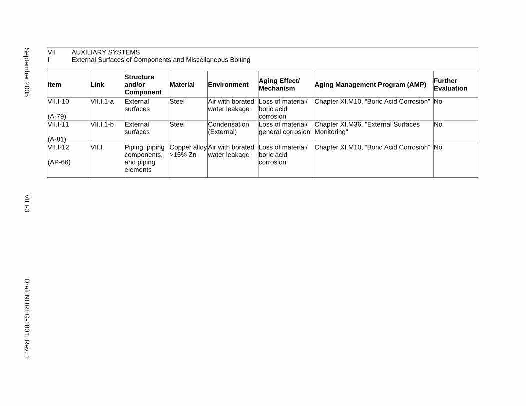
VII AUXILIARY SYSTEMS I External Surfaces of Components and Miscellaneous Bolting
Item Link Structure and/or Component
Material Environment Aging Effect/ Mechanism Aging Management Program (AMP) Further
Evaluation
VII.I-10
(A-79)
VII.I.1-a External surfaces
Steel Air with borated water leakage
Loss of material/ boric acid corrosion
Chapter XI.M10, “Boric Acid Corrosion” No
VII.I-11
(A-81)
VII.I.1-b External surfaces
Steel Condensation (External)
Loss of material/ general corrosion
Chapter XI.M36, "External Surfaces Monitoring"
No
VII.I-12
(AP-66)
VII.I. Piping, piping components, and piping elements
Copper alloy >15% Zn
Air with borated water leakage
Loss of material/ boric acid corrosion
Chapter XI.M10, “Boric Acid Corrosion” No
Septem
ber 2005 V
II I-3 D
raft NU
RE
G-1801, R
ev. 1

This Page Intentionally Left Blank
Draft NUREG-1801, Rev. 1 VII I-4 September 2005
J. COMMON MISCELLANEOUS MATERIAL/ENVIRONMENT COMBINATIONS
Systems, Structures, and Components
This section addresses the aging management programs for miscellaneous material/environment combinations which may be found throughout structures and components for auxiliary systems. For the material/environment combinations in this part, aging effects are not expected to degrade the ability of the structure or component to perform its intended function for the extended period of operation. Therefore, no resulting aging management programs for these structures and components are required.
System Interfaces
The structures and components covered in this section belong to the auxiliary systems in pressurized water reactors (PWRs) and boiling water reactors (BWRs). (For example, see System Interfaces in VII.A to VII.I for details)
September 2005 VII J-1 Draft NUREG-1801, Rev. 1
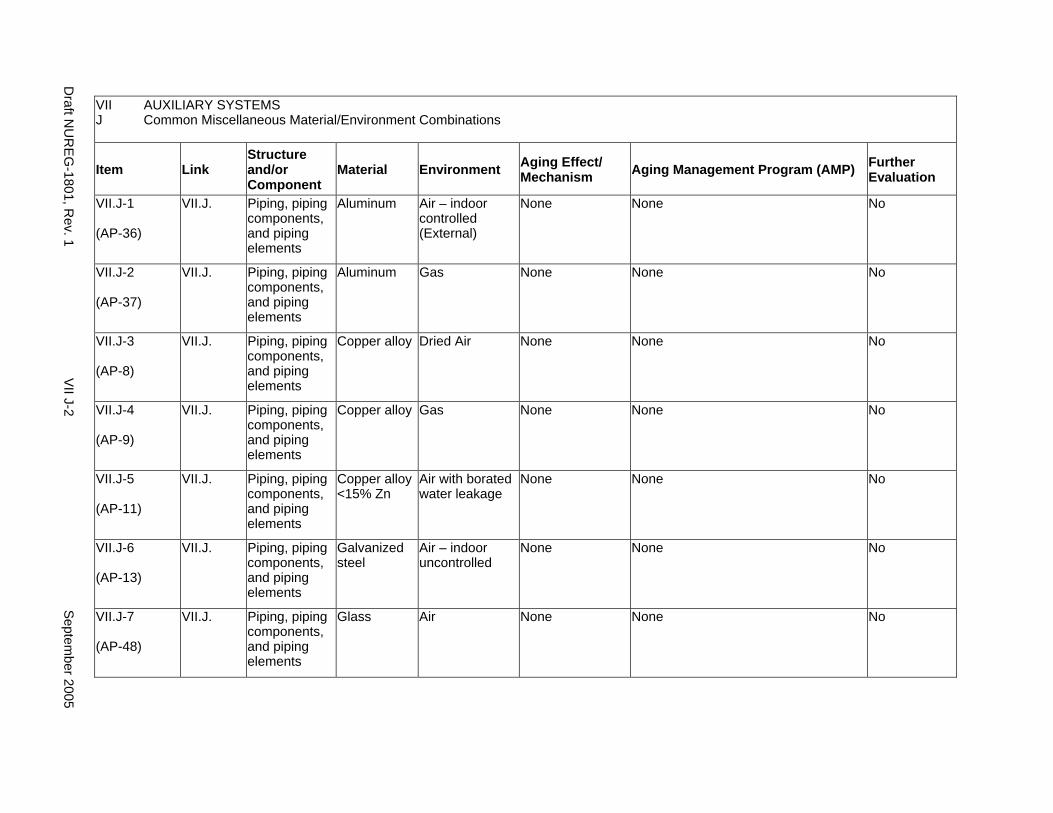
VII AUXILIARY SYSTEMS J Common Miscellaneous Material/Environment Combinations
Item Link Structure and/or Component
Material Environment Aging Effect/ Mechanism Aging Management Program (AMP) Further
Evaluation
VII.J-1
(AP-36)
VII.J. Piping, piping components, and piping elements
Aluminum Air – indoor controlled (External)
None None No
VII.J-2
(AP-37)
VII.J. Piping, piping components, and piping elements
Aluminum Gas None None No
VII.J-3
(AP-8)
VII.J. Piping, piping components, and piping elements
Copper alloy Dried Air None None No
VII.J-4
(AP-9)
VII.J. Piping, piping components, and piping elements
Copper alloy Gas None None No
VII.J-5
(AP-11)
VII.J. Piping, piping components, and piping elements
Copper alloy <15% Zn
Air with borated water leakage
None None No
VII.J-6
(AP-13)
VII.J. Piping, piping components, and piping elements
Galvanized steel
Air – indoor uncontrolled
None None No
VII.J-7
(AP-48)
VII.J. Piping, piping components, and piping elements
Glass Air None None No
Draft N
UR
EG
-1801, Rev. 1
VII J-2
Septem
ber 2005
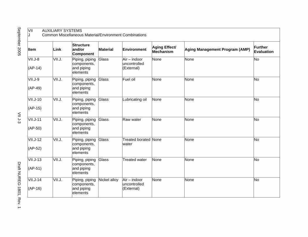
VII AUXILIARY SYSTEMS J Common Miscellaneous Material/Environment Combinations
Item Link Structure and/or Component
Material Environment Aging Effect/ Mechanism Aging Management Program (AMP) Further
Evaluation
VII.J-8
(AP-14)
VII.J. Piping, piping components, and piping elements
Glass Air – indoor uncontrolled (External)
None None No
VII.J-9
(AP-49)
VII.J. Piping, piping components, and piping elements
Glass Fuel oil None None No
VII.J-10
(AP-15)
VII.J. Piping, piping components, and piping elements
Glass Lubricating oil None None No
VII.J-11
(AP-50)
VII.J. Piping, piping components, and piping elements
Glass Raw water None None No
VII.J-12
(AP-52)
VII.J. Piping, piping components, and piping elements
Glass Treated borated water
None None No
VII.J-13
(AP-51)
VII.J. Piping, piping components, and piping elements
Glass Treated water None None No
VII.J-14
(AP-16)
VII.J. Piping, piping components, and piping elements
Nickel alloy Air – indoor uncontrolled (External)
None None No
Septem
ber 2005 V
II J-3 D
raft NU
RE
G-1801, R
ev. 1
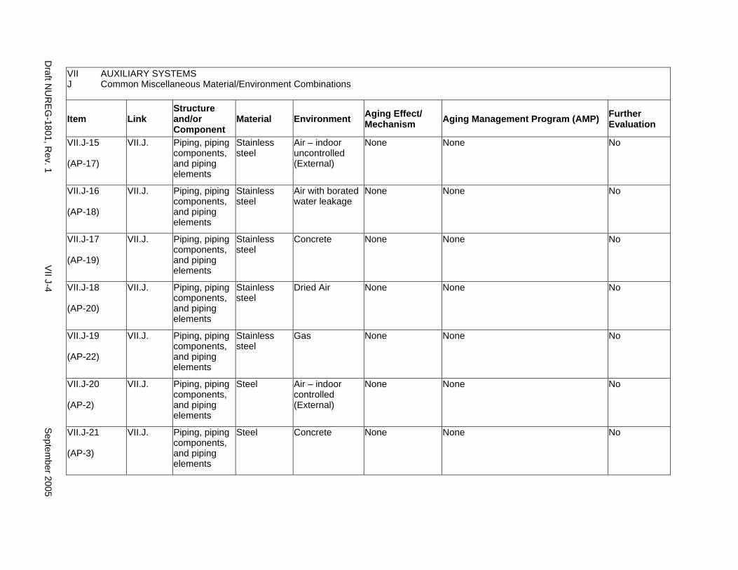
VII AUXILIARY SYSTEMS J Common Miscellaneous Material/Environment Combinations
Item Link Structure and/or Component
Material Environment Aging Effect/ Mechanism Aging Management Program (AMP) Further
Evaluation
VII.J-15
(AP-17)
VII.J. Piping, piping components, and piping elements
Stainless steel
Air – indoor uncontrolled (External)
None None No
VII.J-16
(AP-18)
VII.J. Piping, piping components, and piping elements
Stainless steel
Air with borated water leakage
None None No
VII.J-17
(AP-19)
VII.J. Piping, piping components, and piping elements
Stainless steel
Concrete None None No
VII.J-18
(AP-20)
VII.J. Piping, piping components, and piping elements
Stainless steel
Dried Air None None No
VII.J-19
(AP-22)
VII.J. Piping, piping components, and piping elements
Stainless steel
Gas None None No
VII.J-20
(AP-2)
VII.J. Piping, piping components, and piping elements
Steel Air – indoor controlled (External)
None None No
VII.J-21
(AP-3)
VII.J. Piping, piping components, and piping elements
Steel Concrete None None No
Draft N
UR
EG
-1801, Rev. 1
VII J-4
Septem
ber 2005
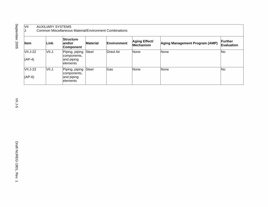
VII AUXILIARY SYSTEMS J Common Miscellaneous Material/Environment Combinations
Item Link Structure and/or Component
Material Environment Aging Effect/ Mechanism Aging Management Program (AMP) Further
Evaluation
VII.J-22
(AP-4)
VII.J. Piping, piping components, and piping elements
Steel Dried Air None None No
VII.J-23
(AP-6)
VII.J. Piping, piping components, and piping elements
Steel Gas None None No
Septem
ber 2005 V
II J-5 D
raft NU
RE
G-1801, R
ev. 1
This Page Intentionally Left Blank
Draft NUREG-1801, Rev. 1 VII J-6 September 2005
CHAPTER VIII
STEAM AND POWER CONVERSION SYSTEM
September 2005 VIII-i Draft NUREG-1801, Rev. 1

This Page Intentionally Left Blank
Draft NUREG-1801, Rev. 1 VIII-ii September 2005
MAJOR PLANT SECTIONS
A. Steam Turbine System
B1. Main Steam System (PWR)
B2. Main Steam System (BWR)
C. Extraction Steam System
D1. Feedwater System (PWR)
D2. Feedwater System (BWR)
E. Condensate System
F. Steam Generator Blowdown System (PWR)
G. Auxiliary Feedwater System (PWR)
H. External Surfaces of Components and Miscellaneous Bolting
I. Common Miscellaneous Material/Environment Combinations
September 2005 VIII-iii Draft NUREG-1801, Rev. 1

This Page Intentionally Left Blank
Draft NUREG-1801, Rev. 1 VIII-iv September 2005
A. STEAM TURBINE SYSTEM
Systems, Structures, and Components
This section addresses the piping and fittings in the steam turbine system for both pressurized water reactors (PWRs) and boiling water reactors (BWRs) and consists of the lines from the high-pressure (HP) turbine to the moisture separator/reheater (MSR), and the lines from the MSR to the low-pressure (LP) turbine. Based on Regulatory Guide 1.26, “Quality Group Classifications and Standards for Water-, Steam-, and Radioactive-Waste-Containing Components of Nuclear Power Plants,” all components that comprise the steam turbine system are governed by Group D Quality Standards.
The steam turbine performs its intended functions with moving parts. They are subject to replacement based on qualified life or specified time period. Pursuant to 10 CFR 54.2(a)(1), therefore, they are not subject to an aging management review.
Aging management programs for the degradation of external surfaces of components and miscellaneous bolting are included in VIII.H. Common miscellaneous material/environment combinations, where aging effects are not expected to degrade the ability of the structure or component to perform its intended function for the extended period of operation, are included in VIII.I.
The system piping includes all pipe sizes, including instrument piping.
System Interfaces
The systems that interface with the steam turbine system include the PWR and BWR main steam system (VIII.B1 and VIII.B2), the extraction steam system (VIII.C), and the condensate system (VIII.E).
September 2005 VIII A-1 Draft NUREG-1801, Rev. 1
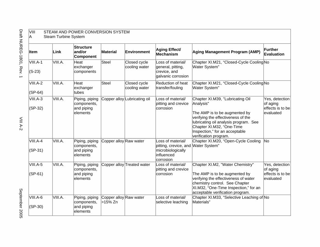
VIII STEAM AND POWER CONVERSION SYSTEM A Steam Turbine System
Item Link Structure and/or Component
Material Environment Aging Effect/ Mechanism Aging Management Program (AMP) Further
Evaluation
VIII.A-1
(S-23)
VIII.A. Heat exchanger components
Steel Closed cycle cooling water
Loss of material/ general, pitting, crevice, and galvanic corrosion
Chapter XI.M21, “Closed-Cycle Cooling Water System”
No
VIII.A-2
(SP-64)
VIII.A. Heat exchanger tubes
Steel Closed cycle cooling water
Reduction of heat transfer/fouling
Chapter XI.M21, “Closed-Cycle Cooling Water System”
No
VIII.A-3
(SP-32)
VIII.A. Piping, piping components, and piping elements
Copper alloy Lubricating oil Loss of material/ pitting and crevice corrosion
Chapter XI.M39, "Lubricating Oil Analysis"
The AMP is to be augmented by verifying the effectiveness of the lubricating oil analysis program. See Chapter XI.M32, “One-Time Inspection,” for an acceptable verification program.
Yes, detection of aging effects is to be evaluated
VIII.A-4
(SP-31)
VIII.A. Piping, piping components, and piping elements
Copper alloy Raw water Loss of material/ pitting, crevice, and microbiologically influenced corrosion
Chapter XI.M20, “Open-Cycle Cooling Water System”
No
VIII.A-5
(SP-61)
VIII.A. Piping, piping components, and piping elements
Copper alloy Treated water Loss of material/ pitting and crevice corrosion
Chapter XI.M2, "Water Chemistry"
The AMP is to be augmented by verifying the effectiveness of water chemistry control. See Chapter XI.M32, “One-Time Inspection,” for an acceptable verification program.
Yes, detection of aging effects is to be evaluated
VIII.A-6
(SP-30)
VIII.A. Piping, piping components, and piping elements
Copper alloy >15% Zn
Raw water Loss of material/ selective leaching
Chapter XI.M33, “Selective Leaching of Materials”
No
Draft N
UR
EG-1801, R
ev. 1 V
III A-2
Septem
ber 2005
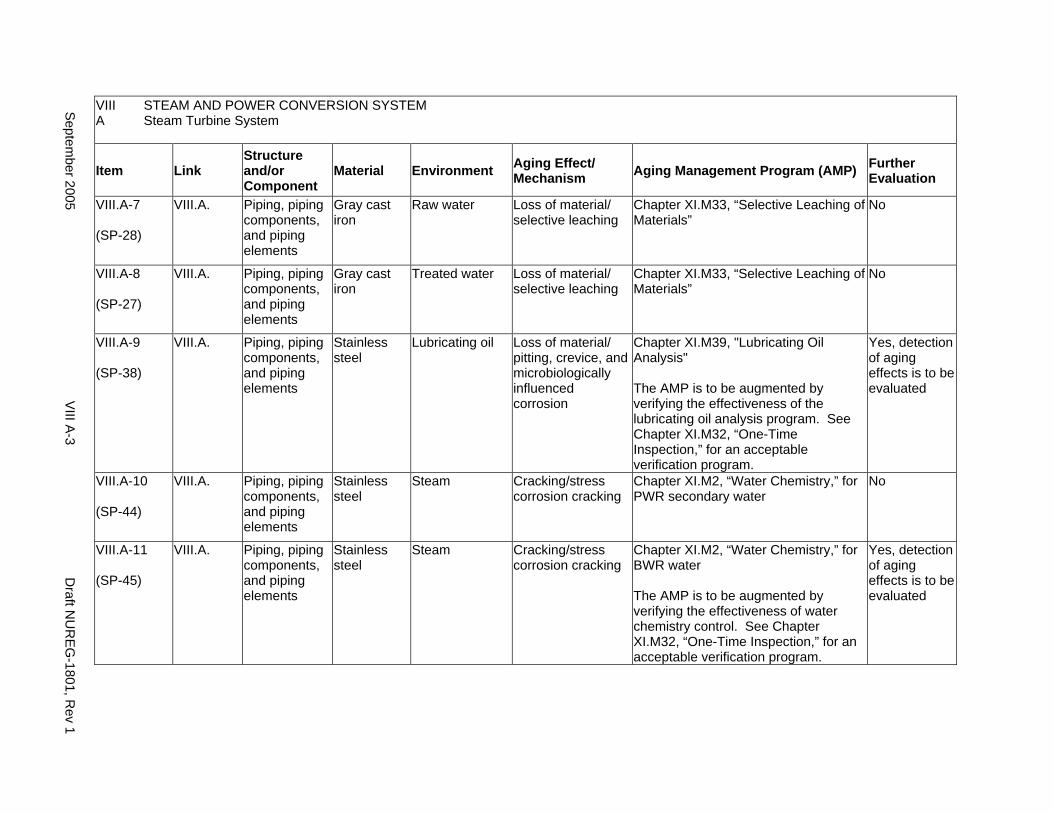
VIII STEAM AND POWER CONVERSION SYSTEM A Steam Turbine System
Item Link Structure and/or Component
Material Environment Aging Effect/ Mechanism Aging Management Program (AMP) Further
Evaluation
VIII.A-7
(SP-28)
VIII.A. Piping, piping components, and piping elements
Gray cast iron
Raw water Loss of material/ selective leaching
Chapter XI.M33, “Selective Leaching of Materials”
No
VIII.A-8
(SP-27)
VIII.A. Piping, piping components, and piping elements
Gray cast iron
Treated water Loss of material/ selective leaching
Chapter XI.M33, “Selective Leaching of Materials”
No
VIII.A-9
(SP-38)
VIII.A. Piping, piping components, and piping elements
Stainless steel
Lubricating oil Loss of material/ pitting, crevice, and microbiologically influenced corrosion
Chapter XI.M39, "Lubricating Oil Analysis"
The AMP is to be augmented by verifying the effectiveness of the lubricating oil analysis program. See Chapter XI.M32, “One-Time Inspection,” for an acceptable verification program.
Yes, detection of aging effects is to be evaluated
VIII.A-10
(SP-44)
VIII.A. Piping, piping components, and piping elements
Stainless steel
Steam Cracking/stress corrosion cracking
Chapter XI.M2, “Water Chemistry,” for PWR secondary water
No
VIII.A-11
(SP-45)
VIII.A. Piping, piping components, and piping elements
Stainless steel
Steam Cracking/stress corrosion cracking
Chapter XI.M2, “Water Chemistry,” for BWR water
The AMP is to be augmented by verifying the effectiveness of water chemistry control. See Chapter XI.M32, “One-Time Inspection,” for an acceptable verification program.
Yes, detection of aging effects is to be evaluated
Septem
ber 2005 V
III A-3
Draft N
UR
EG-1801, R
ev 1
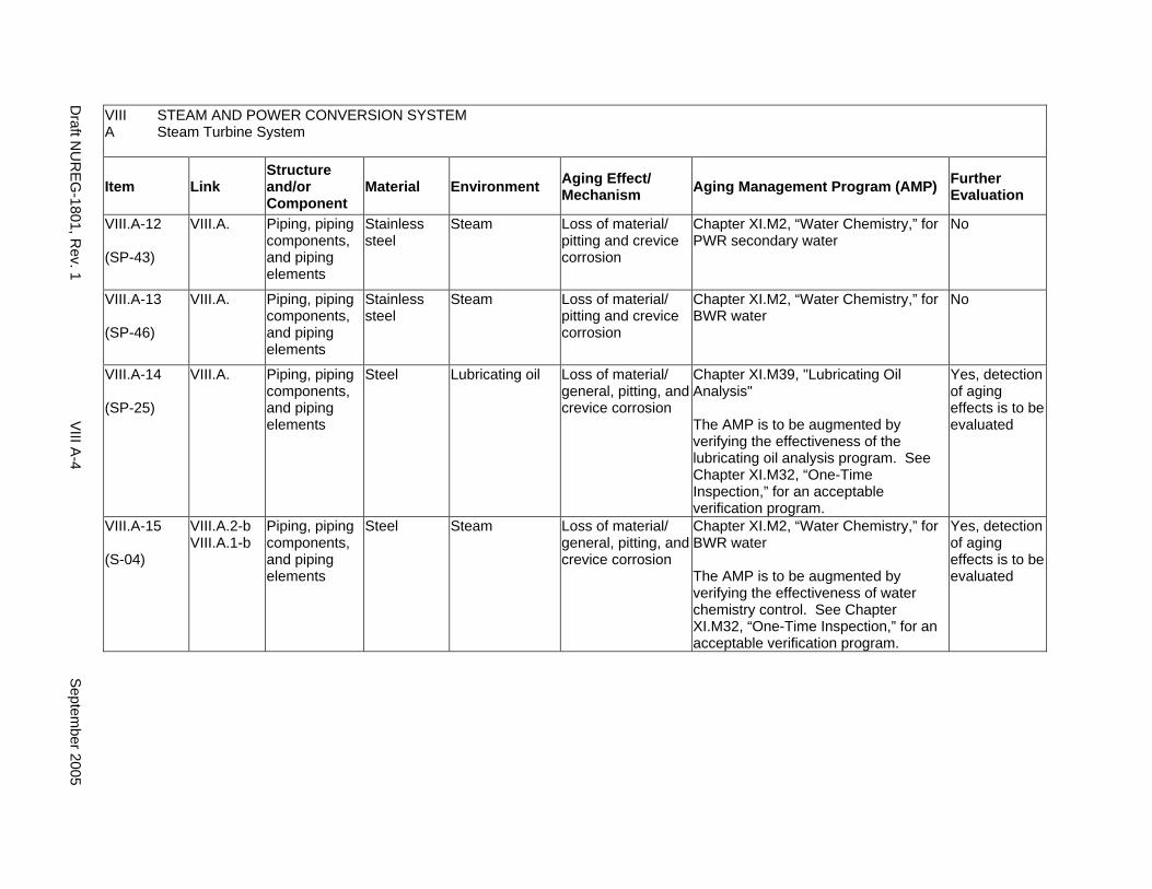
VIII STEAM AND POWER CONVERSION SYSTEM A Steam Turbine System
Item Link Structure and/or Component
Material Environment Aging Effect/ Mechanism Aging Management Program (AMP) Further
Evaluation
VIII.A-12
(SP-43)
VIII.A. Piping, piping components, and piping elements
Stainless steel
Steam Loss of material/ pitting and crevice corrosion
Chapter XI.M2, “Water Chemistry,” for PWR secondary water
No
VIII.A-13
(SP-46)
VIII.A. Piping, piping components, and piping elements
Stainless steel
Steam Loss of material/ pitting and crevice corrosion
Chapter XI.M2, “Water Chemistry,” for BWR water
No
VIII.A-14
(SP-25)
VIII.A. Piping, piping components, and piping elements
Steel Lubricating oil Loss of material/ general, pitting, and crevice corrosion
Chapter XI.M39, "Lubricating Oil Analysis"
The AMP is to be augmented by verifying the effectiveness of the lubricating oil analysis program. See Chapter XI.M32, “One-Time Inspection,” for an acceptable verification program.
Yes, detection of aging effects is to be evaluated
VIII.A-15
(S-04)
VIII.A.2-b VIII.A.1-b
Piping, piping components, and piping elements
Steel Steam Loss of material/ general, pitting, and crevice corrosion
Chapter XI.M2, “Water Chemistry,” for BWR water
The AMP is to be augmented by verifying the effectiveness of water chemistry control. See Chapter XI.M32, “One-Time Inspection,” for an acceptable verification program.
Yes, detection of aging effects is to be evaluated
Draft N
UR
EG-1801, R
ev. 1 V
III A-4
Septem
ber 2005
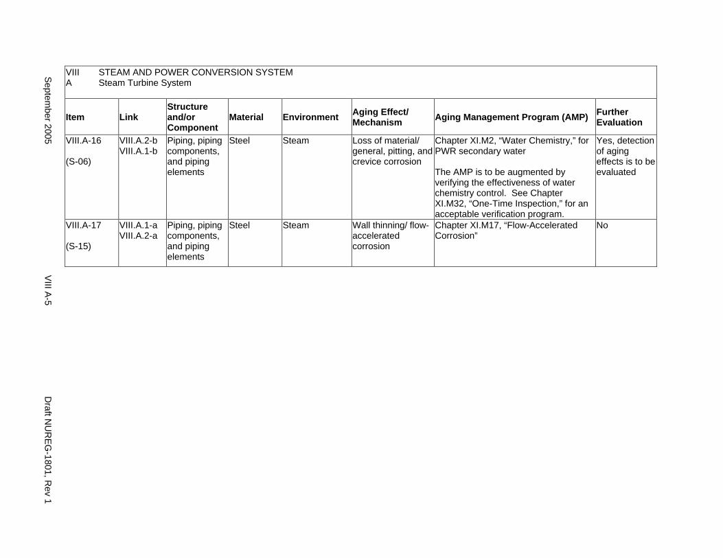
VIII STEAM AND POWER CONVERSION SYSTEM A Steam Turbine System
Item Link Structure and/or Component
Material Environment Aging Effect/ Mechanism Aging Management Program (AMP) Further
Evaluation
VIII.A-16
(S-06)
VIII.A.2-b VIII.A.1-b
Piping, piping components, and piping elements
Steel Steam Loss of material/ general, pitting, and crevice corrosion
Chapter XI.M2, “Water Chemistry,” for PWR secondary water
The AMP is to be augmented by verifying the effectiveness of water chemistry control. See Chapter XI.M32, “One-Time Inspection,” for an acceptable verification program.
Yes, detection of aging effects is to be evaluated
VIII.A-17
(S-15)
VIII.A.1-a VIII.A.2-a
Piping, piping components, and piping elements
Steel Steam Wall thinning/ flow-accelerated corrosion
Chapter XI.M17, “Flow-Accelerated Corrosion”
No
Septem
ber 2005 V
III A-5
Draft N
UR
EG-1801, R
ev 1

This Page Intentionally Left Blank
Draft NUREG-1801, Rev. 1 VIII A-6 September 2005
B1. MAIN STEAM SYSTEM (PWR)
Systems, Structures, and Components
This section addresses the main steam system for pressurized water reactors (PWRs). The section includes the main steam lines from the steam generator to the steam turbine, and the turbine bypass lines from the main steam lines to the condenser. Also included are the lines to the main feedwater (FW) and auxiliary feedwater (AFW) pump turbines, steam drains, and valves, including the containment isolation valves on the main steam lines, and the lines to the AFW pump turbines.
Based on Regulatory Guide 1.26, “Quality Group Classifications and Standards for Water-, Steam-, and Radioactive-Waste-Containing Components of Nuclear Power Plants,” the portion of the main steam system extending from the steam generator up to the second containment isolation valve is governed by Group B or C Quality Standards, and all other components that comprise the main steam system located downstream of these isolation valves are governed by Group D Quality Standards.
The internals of the valves perform their intended functions with moving parts or with a change in configuration. They are subject to replacement based on qualified life or specified time period. Pursuant to 10 CFR 54.21(a)(1), therefore, they are not subject to an aging management review.
Aging management programs for the degradation of the external surfaces of components and miscellaneous bolting are included in VIII.H. Common miscellaneous material/environment combinations, where aging effects are not expected to degrade the ability of the structure or component to perform its intended function for the extended period of operation, are included in VIII.I.
The system piping includes all pipe sizes, including instrument piping.
System Interfaces
The systems and structures that interface with the main steam system include PWR concrete or steel containment structures (II.A1 and II.A2), common components (II.A3), the steam generator (IV.D1 and IV.D2), the steam turbine system (VIII.A), the feedwater system (VIII.D1), the condensate system (VIII.E), and the auxiliary feedwater system (VIII.G).
September 2005 VIII B1-1 Draft NUREG-1801, Rev. 1
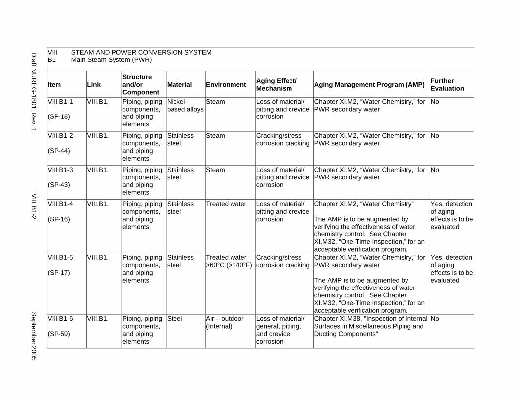
VIII STEAM AND POWER CONVERSION SYSTEM B1 Main Steam System (PWR)
Item Link Structure and/or Component
Material Environment Aging Effect/ Mechanism Aging Management Program (AMP) Further
Evaluation
VIII.B1-1
(SP-18)
VIII.B1. Piping, piping components, and piping elements
Nickel-based alloys
Steam Loss of material/ pitting and crevice corrosion
Chapter XI.M2, “Water Chemistry,” for PWR secondary water
No
VIII.B1-2
(SP-44)
VIII.B1. Piping, piping components, and piping elements
Stainless steel
Steam Cracking/stress corrosion cracking
Chapter XI.M2, “Water Chemistry,” for PWR secondary water
No
VIII.B1-3
(SP-43)
VIII.B1. Piping, piping components, and piping elements
Stainless steel
Steam Loss of material/ pitting and crevice corrosion
Chapter XI.M2, “Water Chemistry,” for PWR secondary water
No
VIII.B1-4
(SP-16)
VIII.B1. Piping, piping components, and piping elements
Stainless steel
Treated water Loss of material/ pitting and crevice corrosion
Chapter XI.M2, “Water Chemistry”
The AMP is to be augmented by verifying the effectiveness of water chemistry control. See Chapter XI.M32, “One-Time Inspection,” for an acceptable verification program.
Yes, detection of aging effects is to be evaluated
VIII.B1-5
(SP-17)
VIII.B1. Piping, piping components, and piping elements
Stainless steel
Treated water >60°C (>140°F)
Cracking/stress corrosion cracking
Chapter XI.M2, “Water Chemistry,” for PWR secondary water
The AMP is to be augmented by verifying the effectiveness of water chemistry control. See Chapter XI.M32, “One-Time Inspection,” for an acceptable verification program.
Yes, detection of aging effects is to be evaluated
VIII.B1-6
(SP-59)
VIII.B1. Piping, piping components, and piping elements
Steel Air – outdoor (Internal)
Loss of material/ general, pitting, and crevice corrosion
Chapter XI.M38, "Inspection of Internal Surfaces in Miscellaneous Piping and Ducting Components"
No
Draft N
UR
EG-1801, R
ev. 1 V
III B1-2
Septem
ber 2005
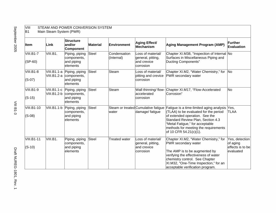
VIII STEAM AND POWER CONVERSION SYSTEM B1 Main Steam System (PWR)
Item Link Structure and/or Component
Material Environment Aging Effect/ Mechanism Aging Management Program (AMP) Further
Evaluation
VIII.B1-7
(SP-60)
VIII.B1. Piping, piping components, and piping elements
Steel Condensation (Internal)
Loss of material/ general, pitting, and crevice corrosion
Chapter XI.M38, "Inspection of Internal Surfaces in Miscellaneous Piping and Ducting Components"
No
VIII.B1-8
(S-07)
VIII.B1.1-a VIII.B1.2-a
Piping, piping components, and piping elements
Steel Steam Loss of material/ pitting and crevice corrosion
Chapter XI.M2, “Water Chemistry,” for PWR secondary water
No
VIII.B1-9
(S-15)
VIII.B1.1-c VIII.B1.2-b
Piping, piping components, and piping elements
Steel Steam Wall thinning/ flow-accelerated corrosion
Chapter XI.M17, “Flow-Accelerated Corrosion”
No
VIII.B1-10
(S-08)
VIII.B1.1-b Piping, piping components, and piping elements
Steel Steam or treated water
Cumulative fatigue damage/ fatigue
Fatigue is a time-limited aging analysis (TLAA) to be evaluated for the period of extended operation. See the Standard Review Plan, Section 4.3 “Metal Fatigue,” for acceptable methods for meeting the requirements of 10 CFR 54.21(c)(1).
Yes, TLAA
VIII.B1-11
(S-10)
VIII.B1. Piping, piping components, and piping elements
Steel Treated water Loss of material/ general, pitting, and crevice corrosion
Chapter XI.M2, “Water Chemistry,” for PWR secondary water
The AMP is to be augmented by verifying the effectiveness of water chemistry control. See Chapter XI.M32, “One-Time Inspection,” for an acceptable verification program.
Yes, detection of aging effects is to be evaluated
Septem
ber 2005 V
III B1-3
Draft N
UR
EG-1801, R
ev. 1

This Page Intentionally Left Blank
Draft NUREG-1801, Rev. 1 VIII B1-4 September 2005
B2. MAIN STEAM SYSTEM (BWR)
Systems, Structures, and Components
This section addresses the main steam system for boiling water reactors (BWRs). The section includes the main steam lines from the outermost containment isolation valve to the steam turbines, and the turbine bypass lines from the main steam lines to the condenser. Also included are steam drains, lines to the main feedwater (FW), high-pressure coolant injection (HPCI), and reactor core isolation cooling (RCIC) turbines.
Based on Regulatory Guide 1.26, “Quality Group Classifications and Standards for Water-, Steam-, and Radioactive-Waste-Containing Components of Nuclear Power Plants,” portions of the main steam system extending from the outermost containment isolation valve up to and including the turbine stop and bypass valves, as well as connected piping up to and including the first valve that is either normally closed or capable of automatic closure during all modes of normal reactor operation, are governed by Group B Quality Standards. The remaining portions of the main steam system consist of components governed by Group D Quality Standards. For BWRs containing a shutoff valve in addition to the two containment isolation valves in the main steam line, Group B Quality Standards apply only to those portions of the system extending from the outermost containment isolation valves up to and including the shutoff valve. The portion of the main steam system extending from the reactor pressure vessel up to the second isolation valve and including the containment isolation valves is governed by Group A Quality Standards, and is covered in IV.C1.
The internal of the valves perform their intended functions with moving parts or with a change in configuration. They are subject to replacement based on qualified life or specified time period. Pursuant to 10 CFR 54.21(a)(1), therefore, they are not subject to an aging management review.
Aging management programs for the degradation of the external surfaces of components and miscellaneous bolting are included in VIII.H. Common miscellaneous material/environment combinations, where aging effects are not expected to degrade the ability of the structure or component to perform its intended function for the extended period of operation, are included in VIII.I.
The system piping includes all pipe sizes, including instrument piping.
System Interfaces
The systems that interface with the main steam system include the BWR Mark 1, Mark 2, or Mark 3 containment structures (II.B1, II.B2, and II.B3, respectively) and common components (II.B4), the reactor coolant pressure boundary (IV.C1), the steam turbine system (VIII.A), the feedwater system (VIII.D2), and the condensate system (VIII.E).
September 2005 VIII B2-1 Draft NUREG-1801, Rev. 1
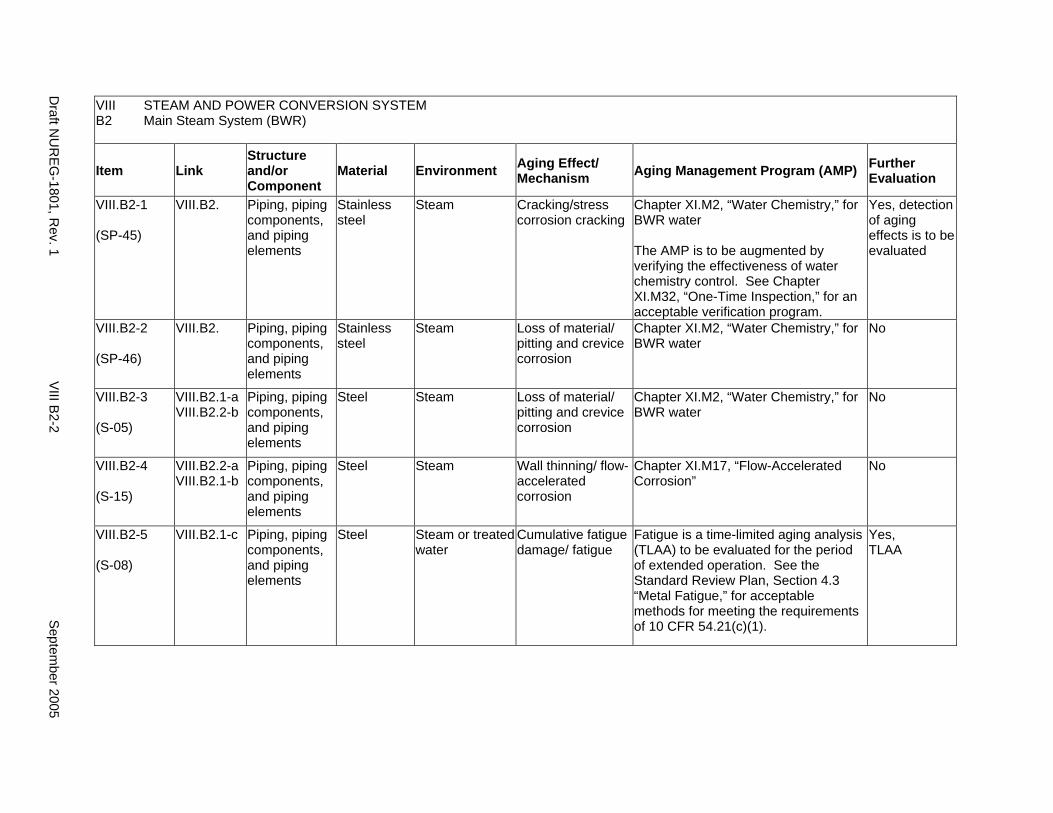
VIII STEAM AND POWER CONVERSION SYSTEM B2 Main Steam System (BWR)
Item Link Structure and/or Component
Material Environment Aging Effect/ Mechanism Aging Management Program (AMP) Further
Evaluation
VIII.B2-1
(SP-45)
VIII.B2. Piping, piping components, and piping elements
Stainless steel
Steam Cracking/stress corrosion cracking
Chapter XI.M2, “Water Chemistry,” for BWR water
The AMP is to be augmented by verifying the effectiveness of water chemistry control. See Chapter XI.M32, “One-Time Inspection,” for an acceptable verification program.
Yes, detection of aging effects is to be evaluated
VIII.B2-2
(SP-46)
VIII.B2. Piping, piping components, and piping elements
Stainless steel
Steam Loss of material/ pitting and crevice corrosion
Chapter XI.M2, “Water Chemistry,” for BWR water
No
VIII.B2-3
(S-05)
VIII.B2.1-a VIII.B2.2-b
Piping, piping components, and piping elements
Steel Steam Loss of material/ pitting and crevice corrosion
Chapter XI.M2, “Water Chemistry,” for BWR water
No
VIII.B2-4
(S-15)
VIII.B2.2-a VIII.B2.1-b
Piping, piping components, and piping elements
Steel Steam Wall thinning/ flow-accelerated corrosion
Chapter XI.M17, “Flow-Accelerated Corrosion”
No
VIII.B2-5
(S-08)
VIII.B2.1-c Piping, piping components, and piping elements
Steel Steam or treated water
Cumulative fatigue damage/ fatigue
Fatigue is a time-limited aging analysis (TLAA) to be evaluated for the period of extended operation. See the Standard Review Plan, Section 4.3 “Metal Fatigue,” for acceptable methods for meeting the requirements of 10 CFR 54.21(c)(1).
Yes, TLAA
Draft N
UR
EG-1801, R
ev. 1 V
III B2-2
Septem
ber 2005
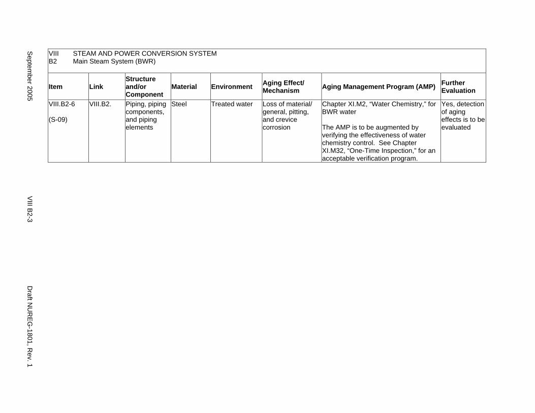
VIII STEAM AND POWER CONVERSION SYSTEM B2 Main Steam System (BWR)
Item Link Structure and/or Component
Material Environment Aging Effect/ Mechanism Aging Management Program (AMP) Further
Evaluation
VIII.B2-6
(S-09)
VIII.B2. Piping, piping components, and piping elements
Steel Treated water Loss of material/ general, pitting, and crevice corrosion
Chapter XI.M2, “Water Chemistry,” for BWR water
The AMP is to be augmented by verifying the effectiveness of water chemistry control. See Chapter XI.M32, “One-Time Inspection,” for an acceptable verification program.
Yes, detection of aging effects is to be evaluated
Septem
ber 2005 V
III B2-3
Draft N
UR
EG-1801, R
ev. 1

This Page Intentionally Left Blank
Draft NUREG-1801, Rev. 1 VIII B2-4 September 2005
C. EXTRACTION STEAM SYSTEM
Systems, Structures, and Components
This section addresses the extraction steam lines for both pressurized water reactors (PWRs) and boiling water reactors (BWRs), which extend from the steam turbine to the feedwater heaters, including the drain lines. Based on Regulatory Guide 1.26, “Quality Group Classifications and Standards for Water-, Steam-, and Radioactive-Waste-Containing Components of Nuclear Power Plants,” all components that comprise the extraction steam system are governed by Group D Quality Standards.
The internals of the valves perform their intended functions with moving parts or with a change in configuration. They are subject to replacement based on qualified life or specified time period. Pursuant to 10 CFR 54.21(a)(1), therefore, they are not subject to an aging management review.
Aging management programs for the degradation of the external surfaces of components and miscellaneous bolting are included in VIII.H. Common miscellaneous material/environment combinations, where aging effects are not expected to degrade the ability of the structure or component to perform its intended function for the extended period of operation, are included in VIII.I.
The system piping includes all pipe sizes, including instrument piping.
System Interfaces
The systems that interface with the extraction steam system include the steam turbine system (VIII.A), the PWR and BWR feedwater system (VIII.D1 and VIII.D2), and the condensate system (VIII.E).
September 2005 VIII C-1 Draft NUREG-1801, Rev. 1
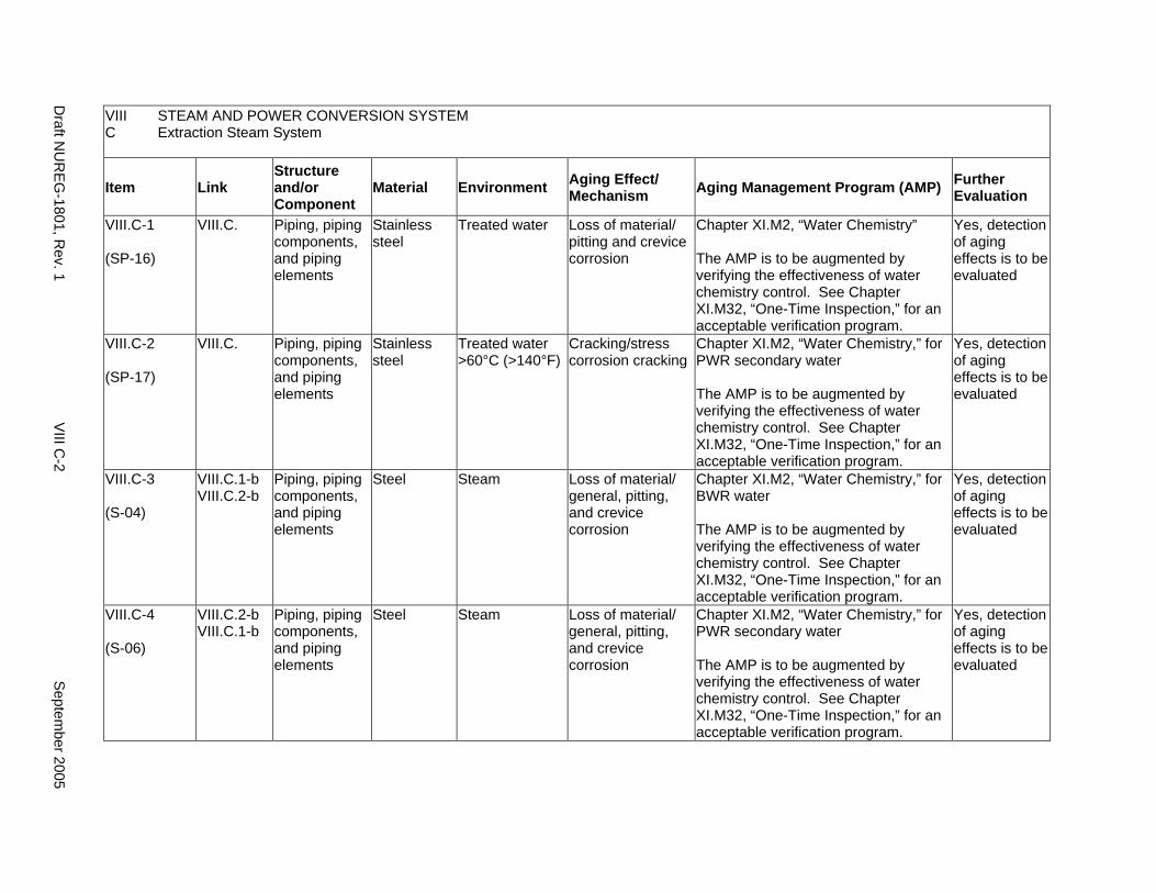
VIII STEAM AND POWER CONVERSION SYSTEM C Extraction Steam System
Item Link Structure and/or Component
Material Environment Aging Effect/ Mechanism Aging Management Program (AMP) Further
Evaluation
VIII.C-1
(SP-16)
VIII.C. Piping, piping components, and piping elements
Stainless steel
Treated water Loss of material/ pitting and crevice corrosion
Chapter XI.M2, “Water Chemistry”
The AMP is to be augmented by verifying the effectiveness of water chemistry control. See Chapter XI.M32, “One-Time Inspection,” for an acceptable verification program.
Yes, detection of aging effects is to be evaluated
VIII.C-2
(SP-17)
VIII.C. Piping, piping components, and piping elements
Stainless steel
Treated water >60°C (>140°F)
Cracking/stress corrosion cracking
Chapter XI.M2, “Water Chemistry,” for PWR secondary water
The AMP is to be augmented by verifying the effectiveness of water chemistry control. See Chapter XI.M32, “One-Time Inspection,” for an acceptable verification program.
Yes, detection of aging effects is to be evaluated
VIII.C-3
(S-04)
VIII.C.1-b VIII.C.2-b
Piping, piping components, and piping elements
Steel Steam Loss of material/ general, pitting, and crevice corrosion
Chapter XI.M2, “Water Chemistry,” for BWR water
The AMP is to be augmented by verifying the effectiveness of water chemistry control. See Chapter XI.M32, “One-Time Inspection,” for an acceptable verification program.
Yes, detection of aging effects is to be evaluated
VIII.C-4
(S-06)
VIII.C.2-b VIII.C.1-b
Piping, piping components, and piping elements
Steel Steam Loss of material/ general, pitting, and crevice corrosion
Chapter XI.M2, “Water Chemistry,” for PWR secondary water
The AMP is to be augmented by verifying the effectiveness of water chemistry control. See Chapter XI.M32, “One-Time Inspection,” for an acceptable verification program.
Yes, detection of aging effects is to be evaluated
Draft N
UR
EG-1801, R
ev. 1 V
III C-2
Septem
ber 2005
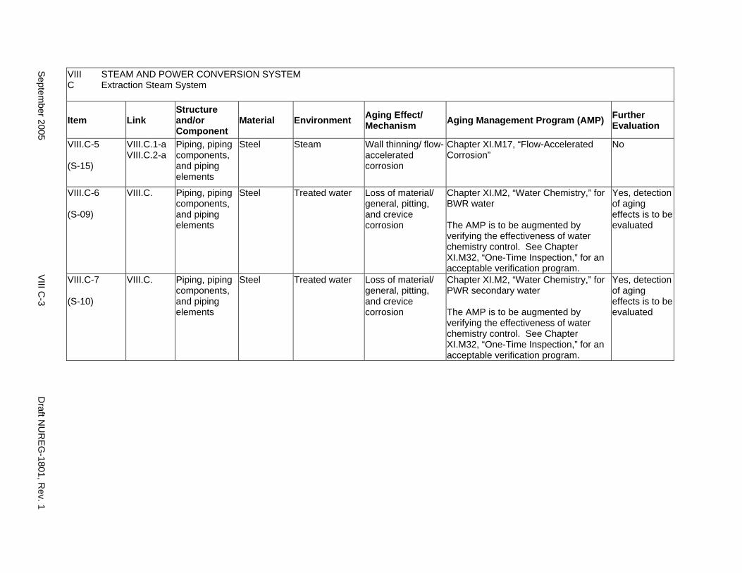
VIII STEAM AND POWER CONVERSION SYSTEM C Extraction Steam System
Item Link Structure and/or Component
Material Environment Aging Effect/ Mechanism Aging Management Program (AMP) Further
Evaluation
VIII.C-5
(S-15)
VIII.C.1-a VIII.C.2-a
Piping, piping components, and piping elements
Steel Steam Wall thinning/ flow-accelerated corrosion
Chapter XI.M17, “Flow-Accelerated Corrosion”
No
VIII.C-6
(S-09)
VIII.C. Piping, piping components, and piping elements
Steel Treated water Loss of material/ general, pitting, and crevice corrosion
Chapter XI.M2, “Water Chemistry,” for BWR water
The AMP is to be augmented by verifying the effectiveness of water chemistry control. See Chapter XI.M32, “One-Time Inspection,” for an acceptable verification program.
Yes, detection of aging effects is to be evaluated
VIII.C-7
(S-10)
VIII.C. Piping, piping components, and piping elements
Steel Treated water Loss of material/ general, pitting, and crevice corrosion
Chapter XI.M2, “Water Chemistry,” for PWR secondary water
The AMP is to be augmented by verifying the effectiveness of water chemistry control. See Chapter XI.M32, “One-Time Inspection,” for an acceptable verification program.
Yes, detection of aging effects is to be evaluated
Septem
ber 2005 VIII C
-3 D
raft NU
REG
-1801, Rev. 1

This Page Intentionally Left Blank
Draft NUREG-1801, Rev. 1 VIII C-4 September 2005

D1. FEEDWATER SYSTEM (PWR)
Systems, Structures, and Components
This section addresses the main feedwater system for pressurized water reactors (PWRs), which extends from the condensate system to the steam generator. It consists of the main feedwater lines, feedwater pumps, and valves, including the containment isolation valves. Based on Regulatory Guide 1.26, “Quality Group Classifications and Standards for Water-, Steam-, and Radioactive-Waste-Containing Components of Nuclear Power Plants,” the portion of the feedwater system extending from the secondary side of the steam generator up to the second containment isolation valve is governed by Group B or C Quality Standards. All other components in the feedwater system located downstream from these isolation valves are governed by Group D Quality Standards.
Pump and valve internals perform their intended functions with moving parts or with a change in configuration. They are subject to replacement based on qualified life or specified time period. Pursuant to 10 CFR 54.21(a)(1), therefore, they not subject to an aging management review.
Aging management programs for the degradation of the external surfaces of components and miscellaneous bolting are included in VIII.H. Common miscellaneous material/environment combinations, where aging effects are not expected to degrade the ability of the structure or component to perform its intended function for the extended period of operation, are included in VIII.I.
The system piping includes all pipe sizes, including instrument piping.
System Interfaces
The systems and structures that interface with the feedwater system include PWR concrete or steel containment structures (II.A1 and II.A2) and common components (II.A3), the steam generators (IV.D1 and IV.D2), the main steam system (VIII.B1), the extraction steam system (VIII.C), the condensate system (VIII.E), and the auxiliary feedwater system (VIII.G).
September 2005 VIII D1-1 Draft NUREG-1801, Rev. 1
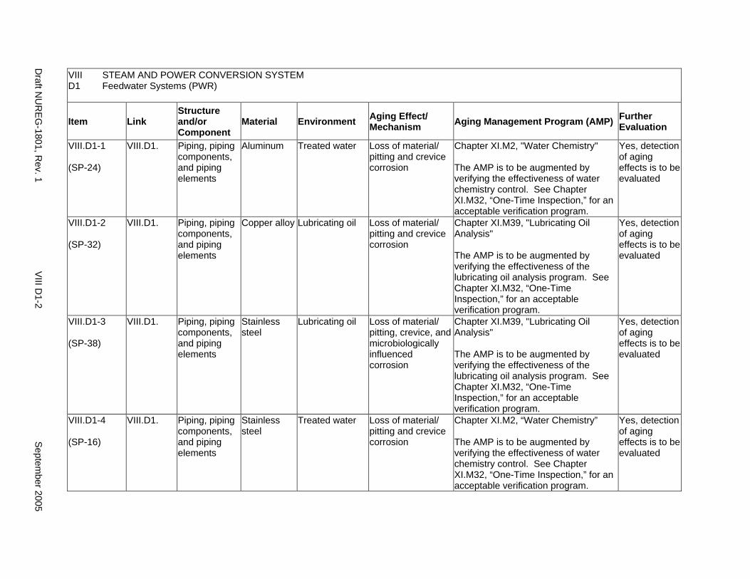
VIII STEAM AND POWER CONVERSION SYSTEM D1 Feedwater Systems (PWR)
Item Link Structure and/or Component
Material Environment Aging Effect/ Mechanism Aging Management Program (AMP) Further
Evaluation
VIII.D1-1
(SP-24)
VIII.D1. Piping, piping components, and piping elements
Aluminum Treated water Loss of material/ pitting and crevice corrosion
Chapter XI.M2, "Water Chemistry"
The AMP is to be augmented by verifying the effectiveness of water chemistry control. See Chapter XI.M32, “One-Time Inspection,” for an acceptable verification program.
Yes, detection of aging effects is to be evaluated
VIII.D1-2
(SP-32)
VIII.D1. Piping, piping components, and piping elements
Copper alloy Lubricating oil Loss of material/ pitting and crevice corrosion
Chapter XI.M39, "Lubricating Oil Analysis"
The AMP is to be augmented by verifying the effectiveness of the lubricating oil analysis program. See Chapter XI.M32, “One-Time Inspection,” for an acceptable verification program.
Yes, detection of aging effects is to be evaluated
VIII.D1-3
(SP-38)
VIII.D1. Piping, piping components, and piping elements
Stainless steel
Lubricating oil Loss of material/ pitting, crevice, and microbiologically influenced corrosion
Chapter XI.M39, "Lubricating Oil Analysis"
The AMP is to be augmented by verifying the effectiveness of the lubricating oil analysis program. See Chapter XI.M32, “One-Time Inspection,” for an acceptable verification program.
Yes, detection of aging effects is to be evaluated
VIII.D1-4
(SP-16)
VIII.D1. Piping, piping components, and piping elements
Stainless steel
Treated water Loss of material/ pitting and crevice corrosion
Chapter XI.M2, “Water Chemistry”
The AMP is to be augmented by verifying the effectiveness of water chemistry control. See Chapter XI.M32, “One-Time Inspection,” for an acceptable verification program.
Yes, detection of aging effects is to be evaluated
Draft N
UR
EG-1801, R
ev. 1 V
III D1-2
Septem
ber 2005
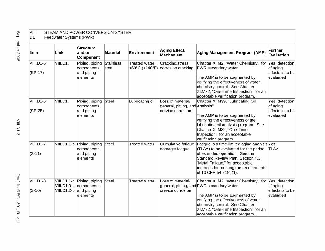
VIII STEAM AND POWER CONVERSION SYSTEM D1 Feedwater Systems (PWR)
Item Link Structure and/or Component
Material Environment Aging Effect/ Mechanism Aging Management Program (AMP) Further
Evaluation
VIII.D1-5
(SP-17)
VIII.D1. Piping, piping components, and piping elements
Stainless steel
Treated water >60°C (>140°F)
Cracking/stress corrosion cracking
Chapter XI.M2, “Water Chemistry,” for PWR secondary water
The AMP is to be augmented by verifying the effectiveness of water chemistry control. See Chapter XI.M32, “One-Time Inspection,” for an acceptable verification program.
Yes, detection of aging effects is to be evaluated
VIII.D1-6
(SP-25)
VIII.D1. Piping, piping components, and piping elements
Steel Lubricating oil Loss of material/ general, pitting, and crevice corrosion
Chapter XI.M39, "Lubricating Oil Analysis"
The AMP is to be augmented by verifying the effectiveness of the lubricating oil analysis program. See Chapter XI.M32, “One-Time Inspection,” for an acceptable verification program.
Yes, detection of aging effects is to be evaluated
VIII.D1-7
(S-11)
VIII.D1.1-b Piping, piping components, and piping elements
Steel Treated water Cumulative fatigue damage/ fatigue
Fatigue is a time-limited aging analysis (TLAA) to be evaluated for the period of extended operation. See the Standard Review Plan, Section 4.3 “Metal Fatigue,” for acceptable methods for meeting the requirements of 10 CFR 54.21(c)(1).
Yes, TLAA
VIII.D1-8
(S-10)
VIII.D1.1-c VIII.D1.3-a VIII.D1.2-b
Piping, piping components, and piping elements
Steel Treated water Loss of material/ general, pitting, and crevice corrosion
Chapter XI.M2, “Water Chemistry,” for PWR secondary water
The AMP is to be augmented by verifying the effectiveness of water chemistry control. See Chapter XI.M32, “One-Time Inspection,” for an acceptable verification program.
Yes, detection of aging effects is to be evaluated
Septem
ber 2005 V
III D1-3
Draft N
UR
EG-1801, R
ev. 1
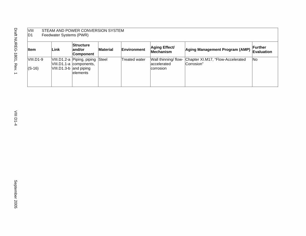
VIII STEAM AND POWER CONVERSION SYSTEM D1 Feedwater Systems (PWR)
Item Link Structure and/or Component
Material Environment Aging Effect/ Mechanism Aging Management Program (AMP) Further
Evaluation
VIII.D1-9
(S-16)
VIII.D1.2-a VIII.D1.1-a VIII.D1.3-b
Piping, piping components, and piping elements
Steel Treated water Wall thinning/ flow-accelerated corrosion
Chapter XI.M17, “Flow-Accelerated Corrosion”
No
Draft N
UR
EG-1801, R
ev. 1 V
III D1-4
Septem
ber 2005
D2. FEEDWATER SYSTEM (BWR)
Systems, Structures, and Components
This section addresses the main feedwater system for boiling water reactors (BWRs), which extends from the condensate and condensate booster system to the outermost feedwater isolation valve on the feedwater lines to the reactor vessel. It consists of the main feedwater lines, feedwater pumps, and valves.
Based on Regulatory Guide 1.26, “Quality Group Classifications and Standards for Water-, Steam-, and Radioactive-Waste-Containing Components of Nuclear Power Plants,” the portions of the feedwater system extending from the outermost containment isolation valves up to and including the shutoff valve, or the first valve that is either normally closed or capable of closure during all modes of normal reactor operation, are governed by Group B Quality Standards. The remaining portions of the feedwater system consist of components governed by Group D Quality Standards. The portion of the feedwater system extending from the reactor vessel up to the second containment isolation valve, including the isolation valves, is governed by Group A Quality Standards and is covered in IV.C1.
Pump and valve internals perform their intended functions with moving parts or with a change in configuration. They are subject to replacement based on qualified life or specified time period. Pursuant to 10 CFR 54.21(a)(1), therefore, they are not subject to an aging management review.
Aging management programs for the degradation of the external surfaces of components and miscellaneous bolting are included in VIII.H. Common miscellaneous material/environment combinations, where aging effects are not expected to degrade the ability of the structure or component to perform its intended function for the extended period of operation, are included in VIII.I.
The system piping includes all pipe sizes, including instrument piping.
System Interfaces
The systems that interface with the feedwater system include the BWR Mark 1, Mark 2, or Mark 3 containment structures (II.B1, II.B2, and II.B3, respectively) and common components (II.B4), the reactor coolant pressure boundary (IV.C1), the main steam system (VIII.B2), the extraction steam system (VIII.C), and the condensate system (VIII.E).
September 2005 VIII D2-1 Draft NUREG-1801, Rev. 1

VIII STEAM AND POWER CONVERSION SYSTEM D2 Feedwater Systems (BWR)
Item Link Structure and/or Component
Material Environment Aging Effect/ Mechanism Aging Management Program (AMP) Further
Evaluation
VIII.D2-1
(SP-24)
VIII.D2. Piping, piping components, and piping elements
Aluminum Treated water Loss of material/ pitting and crevice corrosion
Chapter XI.M2, "Water Chemistry"
The AMP is to be augmented by verifying the effectiveness of water chemistry control. See Chapter XI.M32, “One-Time Inspection,” for an acceptable verification program.
Yes, detection of aging effects is to be evaluated
VIII.D2-2
(SP-32)
VIII.D2. Piping, piping components, and piping elements
Copper alloy Lubricating oil Loss of material/ pitting and crevice corrosion
Chapter XI.M39, "Lubricating Oil Analysis"
The AMP is to be augmented by verifying the effectiveness of the lubricating oil analysis program. See Chapter XI.M32, “One-Time Inspection,” for an acceptable verification program.
Yes, detection of aging effects is to be evaluated
VIII.D2-3
(SP-38)
VIII.D2. Piping, piping components, and piping elements
Stainless steel
Lubricating oil Loss of material/ pitting, crevice, and microbiologically influenced corrosion
Chapter XI.M39, "Lubricating Oil Analysis"
The AMP is to be augmented by verifying the effectiveness of the lubricating oil analysis program. See Chapter XI.M32, “One-Time Inspection,” for an acceptable verification program.
Yes, detection of aging effects is to be evaluated
VIII.D2-4
(SP-16)
VIII.D2. Piping, piping components, and piping elements
Stainless steel
Treated water Loss of material/ pitting and crevice corrosion
Chapter XI.M2, “Water Chemistry”
The AMP is to be augmented by verifying the effectiveness of water chemistry control. See Chapter XI.M32, “One-Time Inspection,” for an acceptable verification program.
Yes, detection of aging effects is to be evaluated
Draft N
UR
EG-1801, R
ev. 1 V
III D2-2
Septem
ber 2005
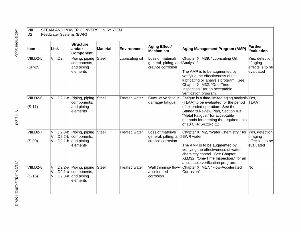
VIII STEAM AND POWER CONVERSION SYSTEM D2 Feedwater Systems (BWR)
Item Link Structure and/or Component
Material Environment Aging Effect/ Mechanism Aging Management Program (AMP) Further
Evaluation
VIII.D2-5
(SP-25)
VIII.D2. Piping, piping components, and piping elements
Steel Lubricating oil Loss of material/ general, pitting, and crevice corrosion
Chapter XI.M39, "Lubricating Oil Analysis"
The AMP is to be augmented by verifying the effectiveness of the lubricating oil analysis program. See Chapter XI.M32, “One-Time Inspection,” for an acceptable verification program.
Yes, detection of aging effects is to be evaluated
VIII.D2-6
(S-11)
VIII.D2.1-c Piping, piping components, and piping elements
Steel Treated water Cumulative fatigue damage/ fatigue
Fatigue is a time-limited aging analysis (TLAA) to be evaluated for the period of extended operation. See the Standard Review Plan, Section 4.3 “Metal Fatigue,” for acceptable methods for meeting the requirements of 10 CFR 54.21(c)(1).
Yes, TLAA
VIII.D2-7
(S-09)
VIII.D2.3-b VIII.D2.2-b VIII.D2.1-b
Piping, piping components, and piping elements
Steel Treated water Loss of material/ general, pitting, and crevice corrosion
Chapter XI.M2, “Water Chemistry,” for BWR water
The AMP is to be augmented by verifying the effectiveness of water chemistry control. See Chapter XI.M32, “One-Time Inspection,” for an acceptable verification program.
Yes, detection of aging effects is to be evaluated
VIII.D2-8
(S-16)
VIII.D2.2-a VIII.D2.1-a VIII.D2.3-a
Piping, piping components, and piping elements
Steel Treated water Wall thinning/ flow-accelerated corrosion
Chapter XI.M17, “Flow-Accelerated Corrosion”
No
Septem
ber 2005 V
III D2-3
Draft N
UR
EG-1801, R
ev. 1

This Page Intentionally Left Blank
Draft NUREG-1801, Rev. 1 VIII D2-4 September 2005
E. CONDENSATE SYSTEM
Systems, Structures, and Components
This section addresses the condensate system for both pressurized water reactors (PWRs) and boiling water reactors (BWRs), which extend from the condenser hotwells to the suction of feedwater pumps, including condensate and condensate booster pumps, condensate coolers, condensate cleanup system, and condensate storage tanks. Based on Regulatory Guide 1.26, “Quality Group Classifications and Standards for Water-, Steam-, and Radioactive-Waste-Containing Components of Nuclear Power Plants,” all components that comprise the condensate system are governed by Group D Quality Standards.
Pump and valve internals perform their intended functions with moving parts or with a change in configuration. They are subject to replacement based on qualified life or specified time period. Pursuant to 10 CFR 54.21(a)(1), therefore, they are not subject to an aging management review.
Aging management programs for the degradation of the external surfaces of components and miscellaneous bolting are included in VIII.H. Common miscellaneous material/environment combinations, where aging effects are not expected to degrade the ability of the structure or component to perform its intended function for the extended period of operation, are included in VIII.I.
The system piping includes all pipe sizes, including instrument piping.
System Interfaces
The systems that interface with the condensate system include the steam turbine system (VIII.A), the PWR and BWR main steam system (VIII.B1 and VIII.B2), the PWR and BWR feedwater system (VIII.D1 and VIII.D2), the auxiliary feedwater system (VIII.G, PWR only), the PWR and BWR reactor water cleanup system (VII.E3), the open or closed cycle cooling water systems (VII.C1 or VII.C2), and the condensate storage facility.
September 2005 VIII E-1 Draft NUREG-1801, Rev. 1
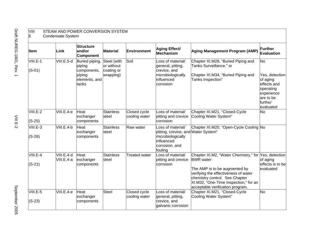
VIII STEAM AND POWER CONVERSION SYSTEM E Condensate System
Item Link Structure and/or Component
Material Environment Aging Effect/ Mechanism Aging Management Program (AMP) Further
Evaluation
VIII.E-1
(S-01)
VIII.E.5-d Buried piping, piping components, piping elements, and tanks
Steel (with or without coating or wrapping)
Soil Loss of material/ general, pitting, crevice, and microbiologically influenced corrosion
Chapter XI.M28, “Buried Piping and Tanks Surveillance,” or
Chapter XI.M34, “Buried Piping and Tanks Inspection”
No
Yes, detection of aging effects and operating experience are to be further evaluated
VIII.E-2
(S-25)
VIII.E.4-e Heat exchanger components
Stainless steel
Closed cycle cooling water
Loss of material/ pitting and crevice corrosion
Chapter XI.M21, “Closed-Cycle Cooling Water System”
No
VIII.E-3
(S-26)
VIII.E.4-b Heat exchanger components
Stainless steel
Raw water Loss of material/ pitting, crevice, and microbiologically influenced corrosion, and fouling
Chapter XI.M20, “Open-Cycle Cooling Water System”
No
VIII.E-4
(S-21)
VIII.E.4-d VIII.E.4-a
Heat exchanger components
Stainless steel
Treated water Loss of material/ pitting and crevice corrosion
Chapter XI.M2, “Water Chemistry,” for BWR water
The AMP is to be augmented by verifying the effectiveness of water chemistry control. See Chapter XI.M32, “One-Time Inspection,” for an acceptable verification program.
Yes, detection of aging effects is to be evaluated
VIII.E-5
(S-23)
VIII.E.4-e Heat exchanger components
Steel Closed cycle cooling water
Loss of material/ general, pitting, crevice, and galvanic corrosion
Chapter XI.M21, “Closed-Cycle Cooling Water System”
No
Draft N
UR
EG-1801, R
ev. 1 V
III E-2
Septem
ber 2005
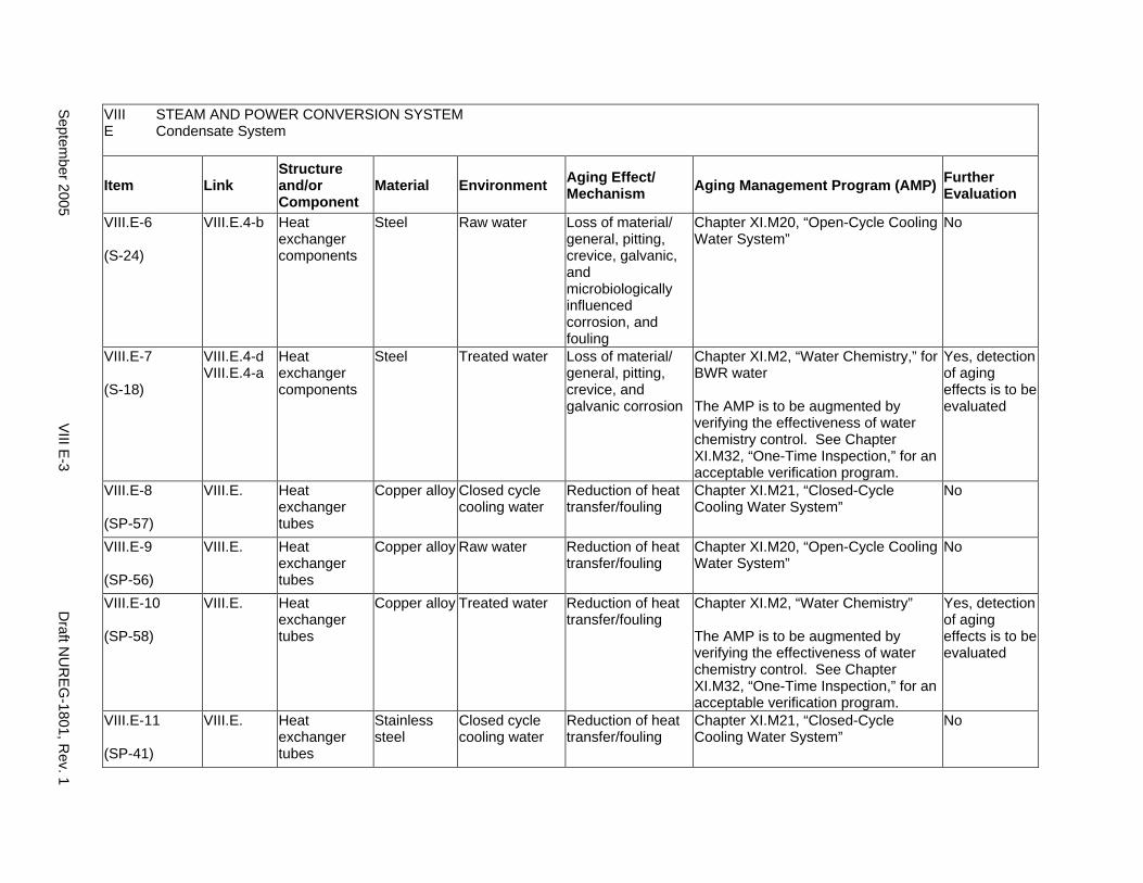
VIII STEAM AND POWER CONVERSION SYSTEM E Condensate System
Item Link Structure and/or Component
Material Environment Aging Effect/ Mechanism Aging Management Program (AMP) Further
Evaluation
VIII.E-6
(S-24)
VIII.E.4-b Heat exchanger components
Steel Raw water Loss of material/ general, pitting, crevice, galvanic, and microbiologically influenced corrosion, and fouling
Chapter XI.M20, “Open-Cycle Cooling Water System”
No
VIII.E-7
(S-18)
VIII.E.4-d VIII.E.4-a
Heat exchanger components
Steel Treated water Loss of material/ general, pitting, crevice, and galvanic corrosion
Chapter XI.M2, “Water Chemistry,” for BWR water
The AMP is to be augmented by verifying the effectiveness of water chemistry control. See Chapter XI.M32, “One-Time Inspection,” for an acceptable verification program.
Yes, detection of aging effects is to be evaluated
VIII.E-8
(SP-57)
VIII.E. Heat exchanger tubes
Copper alloy Closed cycle cooling water
Reduction of heat transfer/fouling
Chapter XI.M21, “Closed-Cycle Cooling Water System”
No
VIII.E-9
(SP-56)
VIII.E. Heat exchanger tubes
Copper alloy Raw water Reduction of heat transfer/fouling
Chapter XI.M20, “Open-Cycle Cooling Water System”
No
VIII.E-10
(SP-58)
VIII.E. Heat exchanger tubes
Copper alloy Treated water Reduction of heat transfer/fouling
Chapter XI.M2, “Water Chemistry”
The AMP is to be augmented by verifying the effectiveness of water chemistry control. See Chapter XI.M32, “One-Time Inspection,” for an acceptable verification program.
Yes, detection of aging effects is to be evaluated
VIII.E-11
(SP-41)
VIII.E. Heat exchanger tubes
Stainless steel
Closed cycle cooling water
Reduction of heat transfer/fouling
Chapter XI.M21, “Closed-Cycle Cooling Water System”
No
Septem
ber 2005 V
III E-3
Draft N
UR
EG-1801, R
ev. 1
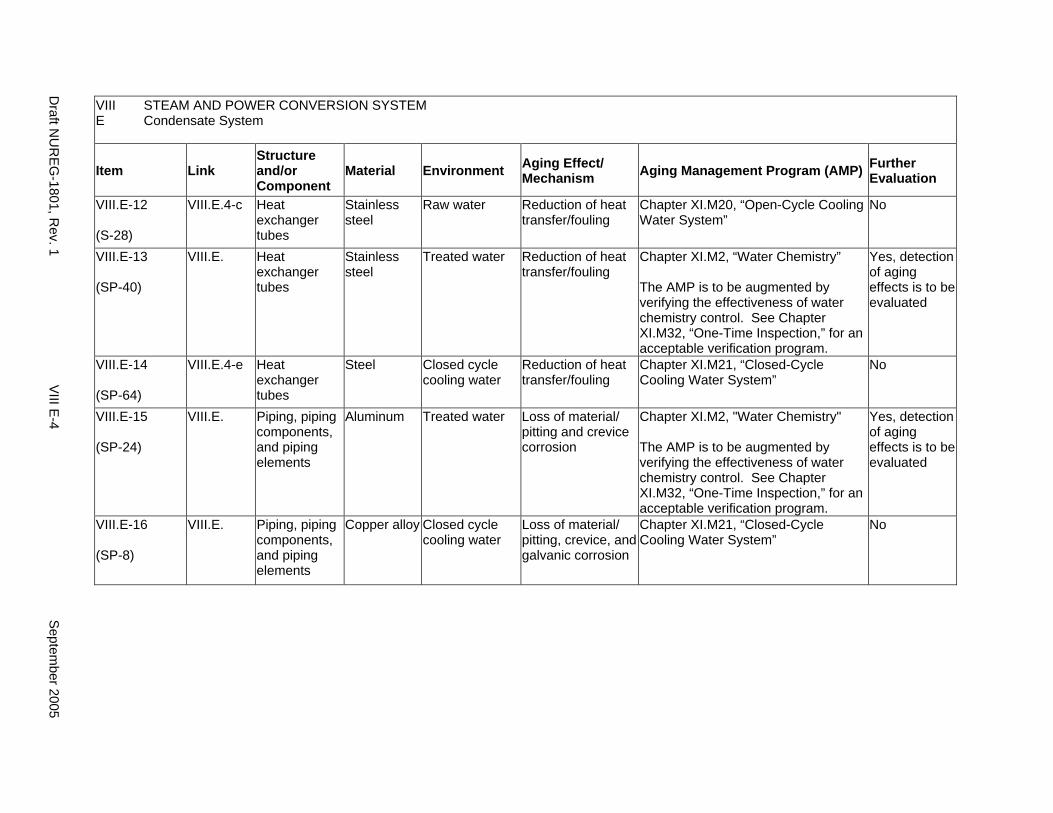
VIII STEAM AND POWER CONVERSION SYSTEM E Condensate System
Item Link Structure and/or Component
Material Environment Aging Effect/ Mechanism Aging Management Program (AMP) Further
Evaluation
VIII.E-12
(S-28)
VIII.E.4-c Heat exchanger tubes
Stainless steel
Raw water Reduction of heat transfer/fouling
Chapter XI.M20, “Open-Cycle Cooling Water System”
No
VIII.E-13
(SP-40)
VIII.E. Heat exchanger tubes
Stainless steel
Treated water Reduction of heat transfer/fouling
Chapter XI.M2, “Water Chemistry”
The AMP is to be augmented by verifying the effectiveness of water chemistry control. See Chapter XI.M32, “One-Time Inspection,” for an acceptable verification program.
Yes, detection of aging effects is to be evaluated
VIII.E-14
(SP-64)
VIII.E.4-e Heat exchanger tubes
Steel Closed cycle cooling water
Reduction of heat transfer/fouling
Chapter XI.M21, “Closed-Cycle Cooling Water System”
No
VIII.E-15
(SP-24)
VIII.E. Piping, piping components, and piping elements
Aluminum Treated water Loss of material/ pitting and crevice corrosion
Chapter XI.M2, "Water Chemistry"
The AMP is to be augmented by verifying the effectiveness of water chemistry control. See Chapter XI.M32, “One-Time Inspection,” for an acceptable verification program.
Yes, detection of aging effects is to be evaluated
VIII.E-16
(SP-8)
VIII.E. Piping, piping components, and piping elements
Copper alloy Closed cycle cooling water
Loss of material/ pitting, crevice, and galvanic corrosion
Chapter XI.M21, “Closed-Cycle Cooling Water System”
No
Draft N
UR
EG-1801, R
ev. 1 V
III E-4
Septem
ber 2005
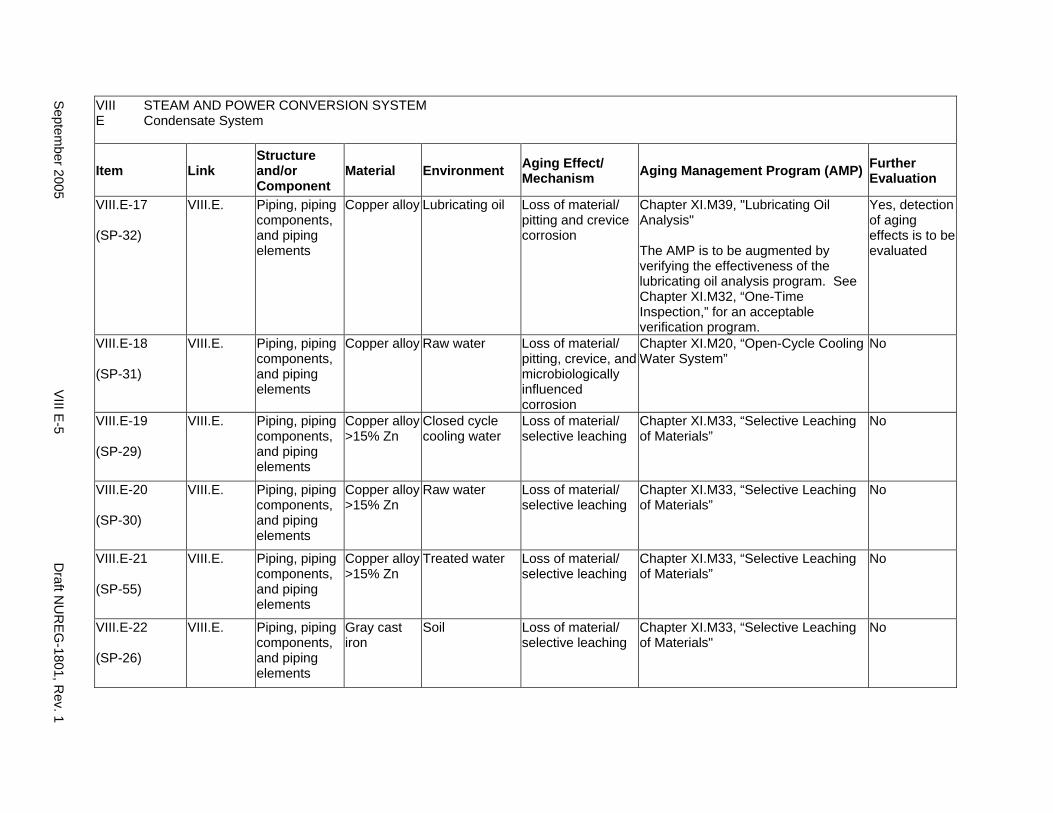
VIII STEAM AND POWER CONVERSION SYSTEM E Condensate System
Item Link Structure and/or Component
Material Environment Aging Effect/ Mechanism Aging Management Program (AMP) Further
Evaluation
VIII.E-17
(SP-32)
VIII.E. Piping, piping components, and piping elements
Copper alloy Lubricating oil Loss of material/ pitting and crevice corrosion
Chapter XI.M39, "Lubricating Oil Analysis"
The AMP is to be augmented by verifying the effectiveness of the lubricating oil analysis program. See Chapter XI.M32, “One-Time Inspection,” for an acceptable verification program.
Yes, detection of aging effects is to be evaluated
VIII.E-18
(SP-31)
VIII.E. Piping, piping components, and piping elements
Copper alloy Raw water Loss of material/ pitting, crevice, and microbiologically influenced corrosion
Chapter XI.M20, “Open-Cycle Cooling Water System”
No
VIII.E-19
(SP-29)
VIII.E. Piping, piping components, and piping elements
Copper alloy >15% Zn
Closed cycle cooling water
Loss of material/ selective leaching
Chapter XI.M33, “Selective Leaching of Materials”
No
VIII.E-20
(SP-30)
VIII.E. Piping, piping components, and piping elements
Copper alloy >15% Zn
Raw water Loss of material/ selective leaching
Chapter XI.M33, “Selective Leaching of Materials”
No
VIII.E-21
(SP-55)
VIII.E. Piping, piping components, and piping elements
Copper alloy >15% Zn
Treated water Loss of material/ selective leaching
Chapter XI.M33, “Selective Leaching of Materials”
No
VIII.E-22
(SP-26)
VIII.E. Piping, piping components, and piping elements
Gray cast iron
Soil Loss of material/ selective leaching
Chapter XI.M33, “Selective Leaching of Materials"
No
Septem
ber 2005 V
III E-5
Draft N
UR
EG-1801, R
ev. 1
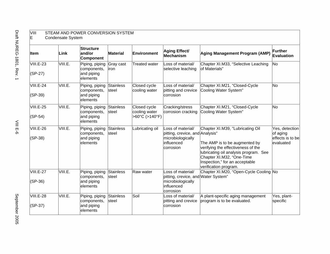
VIII STEAM AND POWER CONVERSION SYSTEM E Condensate System
Item Link Structure and/or Component
Material Environment Aging Effect/ Mechanism Aging Management Program (AMP) Further
Evaluation
VIII.E-23
(SP-27)
VIII.E. Piping, piping components, and piping elements
Gray cast iron
Treated water Loss of material/ selective leaching
Chapter XI.M33, “Selective Leaching of Materials”
No
VIII.E-24
(SP-39)
VIII.E. Piping, piping components, and piping elements
Stainless steel
Closed cycle cooling water
Loss of material/ pitting and crevice corrosion
Chapter XI.M21, “Closed-Cycle Cooling Water System”
No
VIII.E-25
(SP-54)
VIII.E. Piping, piping components, and piping elements
Stainless steel
Closed cycle cooling water >60°C (>140°F)
Cracking/stress corrosion cracking
Chapter XI.M21, “Closed-Cycle Cooling Water System”
No
VIII.E-26
(SP-38)
VIII.E. Piping, piping components, and piping elements
Stainless steel
Lubricating oil Loss of material/ pitting, crevice, and microbiologically influenced corrosion
Chapter XI.M39, "Lubricating Oil Analysis"
The AMP is to be augmented by verifying the effectiveness of the lubricating oil analysis program. See Chapter XI.M32, “One-Time Inspection,” for an acceptable verification program.
Yes, detection of aging effects is to be evaluated
VIII.E-27
(SP-36)
VIII.E. Piping, piping components, and piping elements
Stainless steel
Raw water Loss of material/ pitting, crevice, and microbiologically influenced corrosion
Chapter XI.M20, “Open-Cycle Cooling Water System”
No
VIII.E-28
(SP-37)
VIII.E. Piping, piping components, and piping elements
Stainless steel
Soil Loss of material/ pitting and crevice corrosion
A plant-specific aging management program is to be evaluated.
Yes, plant-specific
Draft N
UR
EG-1801, R
ev. 1 V
III E-6
Septem
ber 2005
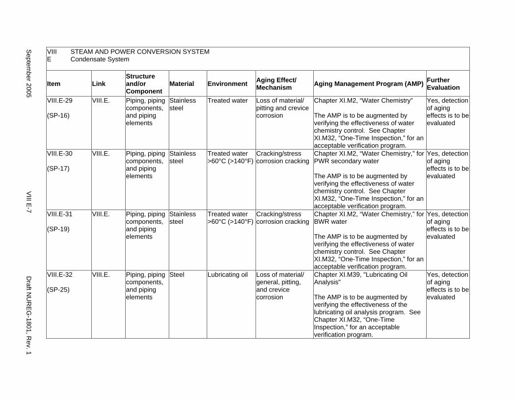
VIII STEAM AND POWER CONVERSION SYSTEM E Condensate System
Item Link Structure and/or Component
Material Environment Aging Effect/ Mechanism Aging Management Program (AMP) Further
Evaluation
VIII.E-29
(SP-16)
VIII.E. Piping, piping components, and piping elements
Stainless steel
Treated water Loss of material/ pitting and crevice corrosion
Chapter XI.M2, “Water Chemistry”
The AMP is to be augmented by verifying the effectiveness of water chemistry control. See Chapter XI.M32, “One-Time Inspection,” for an acceptable verification program.
Yes, detection of aging effects is to be evaluated
VIII.E-30
(SP-17)
VIII.E. Piping, piping components, and piping elements
Stainless steel
Treated water >60°C (>140°F)
Cracking/stress corrosion cracking
Chapter XI.M2, “Water Chemistry,” for PWR secondary water
The AMP is to be augmented by verifying the effectiveness of water chemistry control. See Chapter XI.M32, “One-Time Inspection,” for an acceptable verification program.
Yes, detection of aging effects is to be evaluated
VIII.E-31
(SP-19)
VIII.E. Piping, piping components, and piping elements
Stainless steel
Treated water >60°C (>140°F)
Cracking/stress corrosion cracking
Chapter XI.M2, “Water Chemistry,” for BWR water
The AMP is to be augmented by verifying the effectiveness of water chemistry control. See Chapter XI.M32, “One-Time Inspection,” for an acceptable verification program.
Yes, detection of aging effects is to be evaluated
VIII.E-32
(SP-25)
VIII.E. Piping, piping components, and piping elements
Steel Lubricating oil Loss of material/ general, pitting, and crevice corrosion
Chapter XI.M39, "Lubricating Oil Analysis"
The AMP is to be augmented by verifying the effectiveness of the lubricating oil analysis program. See Chapter XI.M32, “One-Time Inspection,” for an acceptable verification program.
Yes, detection of aging effects is to be evaluated
Septem
ber 2005 V
III E-7
Draft N
UR
EG-1801, R
ev. 1
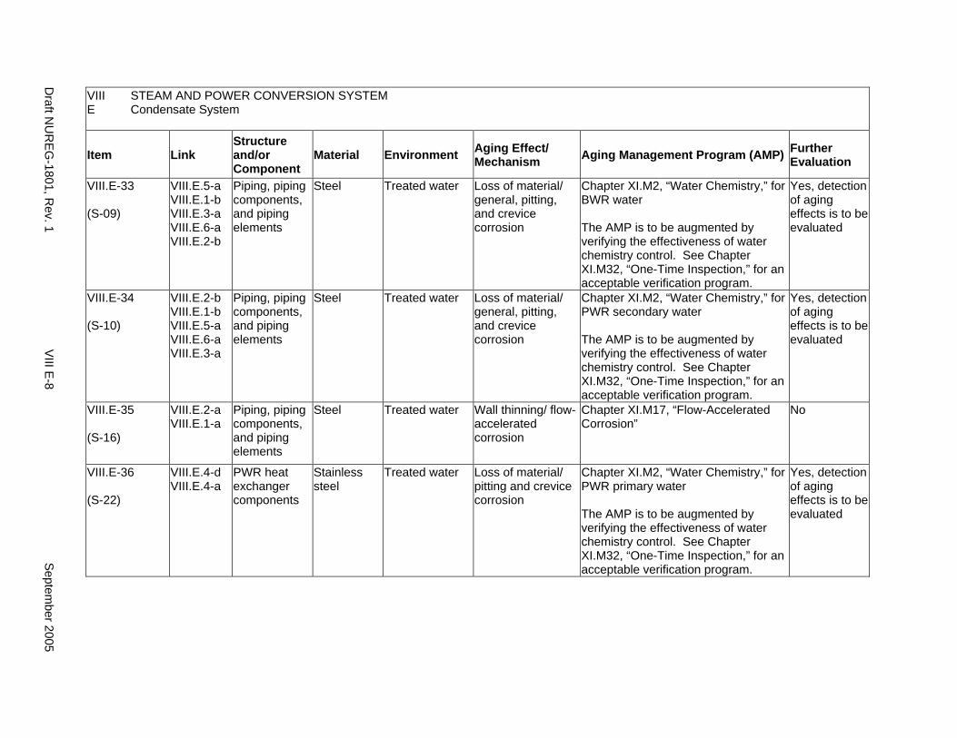
VIII STEAM AND POWER CONVERSION SYSTEM E Condensate System
Item Link Structure and/or Component
Material Environment Aging Effect/ Mechanism Aging Management Program (AMP) Further
Evaluation
VIII.E-33
(S-09)
VIII.E.5-a VIII.E.1-b VIII.E.3-a VIII.E.6-a VIII.E.2-b
Piping, piping components, and piping elements
Steel Treated water Loss of material/ general, pitting, and crevice corrosion
Chapter XI.M2, “Water Chemistry,” for BWR water
The AMP is to be augmented by verifying the effectiveness of water chemistry control. See Chapter XI.M32, “One-Time Inspection,” for an acceptable verification program.
Yes, detection of aging effects is to be evaluated
VIII.E-34
(S-10)
VIII.E.2-b VIII.E.1-b VIII.E.5-a VIII.E.6-a VIII.E.3-a
Piping, piping components, and piping elements
Steel Treated water Loss of material/ general, pitting, and crevice corrosion
Chapter XI.M2, “Water Chemistry,” for PWR secondary water
The AMP is to be augmented by verifying the effectiveness of water chemistry control. See Chapter XI.M32, “One-Time Inspection,” for an acceptable verification program.
Yes, detection of aging effects is to be evaluated
VIII.E-35
(S-16)
VIII.E.2-a VIII.E.1-a
Piping, piping components, and piping elements
Steel Treated water Wall thinning/ flow-accelerated corrosion
Chapter XI.M17, “Flow-Accelerated Corrosion”
No
VIII.E-36
(S-22)
VIII.E.4-d VIII.E.4-a
PWR heat exchanger components
Stainless steel
Treated water Loss of material/ pitting and crevice corrosion
Chapter XI.M2, “Water Chemistry,” for PWR primary water
The AMP is to be augmented by verifying the effectiveness of water chemistry control. See Chapter XI.M32, “One-Time Inspection,” for an acceptable verification program.
Yes, detection of aging effects is to be evaluated
Draft N
UR
EG-1801, R
ev. 1 V
III E-8
Septem
ber 2005
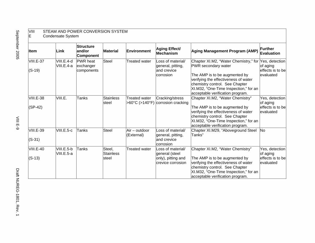
VIII STEAM AND POWER CONVERSION SYSTEM E Condensate System
Item Link Structure and/or Component
Material Environment Aging Effect/ Mechanism Aging Management Program (AMP) Further
Evaluation
VIII.E-37
(S-19)
VIII.E.4-d VIII.E.4-a
PWR heat exchanger components
Steel Treated water Loss of material/ general, pitting, and crevice corrosion
Chapter XI.M2, “Water Chemistry,” for PWR secondary water
The AMP is to be augmented by verifying the effectiveness of water chemistry control. See Chapter XI.M32, “One-Time Inspection,” for an acceptable verification program.
Yes, detection of aging effects is to be evaluated
VIII.E-38
(SP-42)
VIII.E. Tanks Stainless steel
Treated water >60°C (>140°F)
Cracking/stress corrosion cracking
Chapter XI.M2, “Water Chemistry”
The AMP is to be augmented by verifying the effectiveness of water chemistry control. See Chapter XI.M32, “One-Time Inspection,” for an acceptable verification program.
Yes, detection of aging effects is to be evaluated
VIII.E-39
(S-31)
VIII.E.5-c Tanks Steel Air – outdoor (External)
Loss of material/ general, pitting, and crevice corrosion
Chapter XI.M29, “Aboveground Steel Tanks”
No
VIII.E-40
(S-13)
VIII.E.5-b VIII.E.5-a
Tanks Steel, Stainless steel
Treated water Loss of material/ general (steel only), pitting and crevice corrosion
Chapter XI.M2, “Water Chemistry”
The AMP is to be augmented by verifying the effectiveness of water chemistry control. See Chapter XI.M32, “One-Time Inspection,” for an acceptable verification program.
Yes, detection of aging effects is to be evaluated
Septem
ber 2005 V
III E-9
Draft N
UR
EG-1801, R
ev. 1

This Page Intentionally Left Blank
Draft NUREG-1801, Rev. 1 VIII E-10 September 2005
F. STEAM GENERATOR BLOWDOWN SYSTEM (PWR)
Systems, Structures, and Components
This section addresses the steam generator blowdown system for pressurized water reactors (PWRs), which extends from the steam generator through the blowdown condenser and includes the containment isolation valves and small bore piping less than nominal pipe size (NPS) 2 in. (including instrumentation lines).
Based on Regulatory Guide 1.26, “Quality Group Classifications and Standards for Water-, Steam-, and Radioactive-Waste-Containing Components of Nuclear Power Plants,” the portion of the blowdown system extending from the steam generator up to the isolation valve outside the containment and including the isolation valves is governed by Group B or C Quality Standards. The remaining portions of the steam generator blowdown system consist of components governed by Group D Quality Standards.
Pump and valve internals perform their intended functions with moving parts or with a change in configuration. They are subject to replacement based on qualified life or specified time period. Pursuant to 10 CFR 54.21(a)(1), therefore, they are not subject to an aging management review.
Aging management programs for the degradation of the external surfaces of components and miscellaneous bolting are included in VIII.H. Common miscellaneous material/environment combinations, where aging effects are not expected to degrade the ability of the structure or component to perform its intended function for the extended period of operation, are included in VIII.I.
The system piping includes all pipe sizes, including instrument piping.
System Interfaces
The systems that interface with the blowdown system include the steam generator (IV.D1 and IV.D2) and the open- or closed-cycle cooling water systems (VII.C1 or VII.C2).
September 2005 VIII F-1 Draft NUREG-1801, Rev. 1

VIII STEAM AND POWER CONVERSION SYSTEM F Steam Generator Blowdown System (PWR)
Item Link Structure and/or Component
Material Environment Aging Effect/ Mechanism Aging Management Program (AMP) Further
Evaluation
VIII.F-1
(S-25)
VIII.F.4-e Heat exchanger components
Stainless steel
Closed cycle cooling water
Loss of material/ pitting and crevice corrosion
Chapter XI.M21, “Closed-Cycle Cooling Water System”
No
VIII.F-2
(S-26)
VIII.F.4-b Heat exchanger components
Stainless steel
Raw water Loss of material/ pitting, crevice, and microbiologically influenced corrosion, and fouling
Chapter XI.M20, “Open-Cycle Cooling Water System”
No
VIII.F-3
(S-39)
VIII.F.4-a Heat exchanger components
Stainless steel
Treated water >60°C (>140°F)
Cracking/stress corrosion cracking
Chapter XI.M2, “Water Chemistry,” for PWR secondary water
The AMP is to be augmented by verifying the effectiveness of water chemistry control. See Chapter XI.M32, “One-Time Inspection,” for an acceptable verification program.
Yes, detection of aging effects is to be evaluated
VIII.F-4
(S-23)
VIII.F.4-e Heat exchanger components
Steel Closed cycle cooling water
Loss of material/ general, pitting, crevice, and galvanic corrosion
Chapter XI.M21, “Closed-Cycle Cooling Water System”
No
VIII.F-5
(S-24)
VIII.F.4-b Heat exchanger components
Steel Raw water Loss of material/ general, pitting, crevice, galvanic, and microbiologically influenced corrosion, and fouling
Chapter XI.M20, “Open-Cycle Cooling Water System”
No
VIII.F-6
(SP-56)
VIII.F. Heat exchanger tubes
Copper alloy Raw water Reduction of heat transfer/fouling
Chapter XI.M20, “Open-Cycle Cooling Water System”
No
Draft N
UR
EG-1801, R
ev. 1 V
III F-2 S
eptember 2005
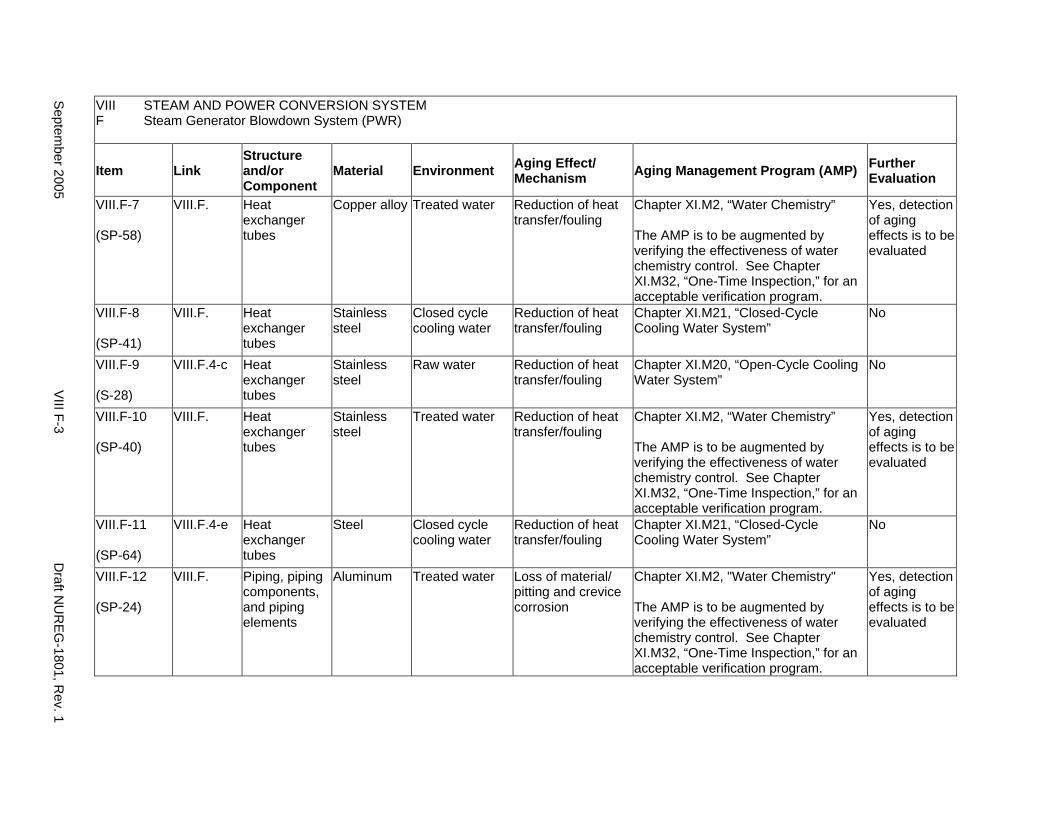
VIII STEAM AND POWER CONVERSION SYSTEM F Steam Generator Blowdown System (PWR)
Item Link Structure and/or Component
Material Environment Aging Effect/ Mechanism Aging Management Program (AMP) Further
Evaluation
VIII.F-7
(SP-58)
VIII.F. Heat exchanger tubes
Copper alloy Treated water Reduction of heat transfer/fouling
Chapter XI.M2, “Water Chemistry”
The AMP is to be augmented by verifying the effectiveness of water chemistry control. See Chapter XI.M32, “One-Time Inspection,” for an acceptable verification program.
Yes, detection of aging effects is to be evaluated
VIII.F-8
(SP-41)
VIII.F. Heat exchanger tubes
Stainless steel
Closed cycle cooling water
Reduction of heat transfer/fouling
Chapter XI.M21, “Closed-Cycle Cooling Water System”
No
VIII.F-9
(S-28)
VIII.F.4-c Heat exchanger tubes
Stainless steel
Raw water Reduction of heat transfer/fouling
Chapter XI.M20, “Open-Cycle Cooling Water System”
No
VIII.F-10
(SP-40)
VIII.F. Heat exchanger tubes
Stainless steel
Treated water Reduction of heat transfer/fouling
Chapter XI.M2, “Water Chemistry”
The AMP is to be augmented by verifying the effectiveness of water chemistry control. See Chapter XI.M32, “One-Time Inspection,” for an acceptable verification program.
Yes, detection of aging effects is to be evaluated
VIII.F-11
(SP-64)
VIII.F.4-e Heat exchanger tubes
Steel Closed cycle cooling water
Reduction of heat transfer/fouling
Chapter XI.M21, “Closed-Cycle Cooling Water System”
No
VIII.F-12
(SP-24)
VIII.F. Piping, piping components, and piping elements
Aluminum Treated water Loss of material/ pitting and crevice corrosion
Chapter XI.M2, "Water Chemistry"
The AMP is to be augmented by verifying the effectiveness of water chemistry control. See Chapter XI.M32, “One-Time Inspection,” for an acceptable verification program.
Yes, detection of aging effects is to be evaluated
Septem
ber 2005 V
III F-3 D
raft NU
REG
-1801, Rev. 1
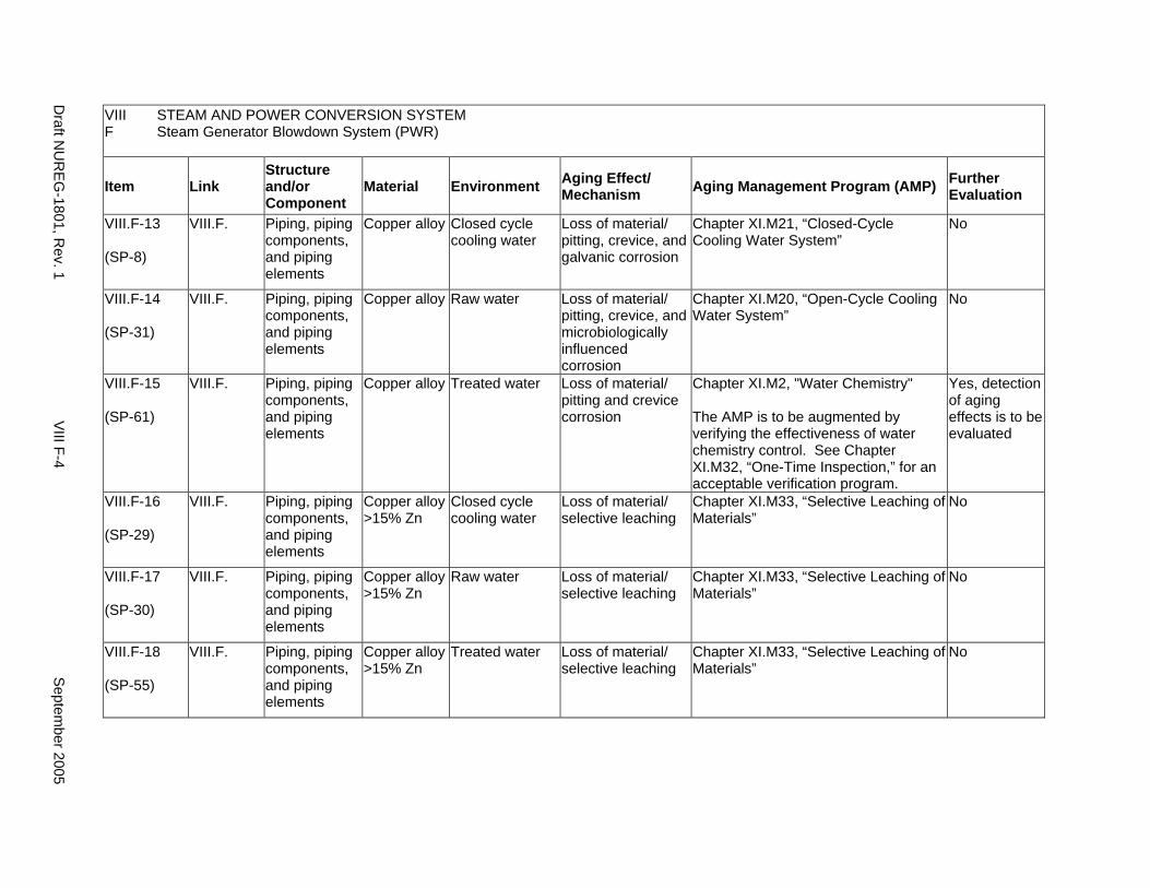
VIII STEAM AND POWER CONVERSION SYSTEM F Steam Generator Blowdown System (PWR)
Item Link Structure and/or Component
Material Environment Aging Effect/ Mechanism Aging Management Program (AMP) Further
Evaluation
VIII.F-13
(SP-8)
VIII.F. Piping, piping components, and piping elements
Copper alloy Closed cycle cooling water
Loss of material/ pitting, crevice, and galvanic corrosion
Chapter XI.M21, “Closed-Cycle Cooling Water System”
No
VIII.F-14
(SP-31)
VIII.F. Piping, piping components, and piping elements
Copper alloy Raw water Loss of material/ pitting, crevice, and microbiologically influenced corrosion
Chapter XI.M20, “Open-Cycle Cooling Water System”
No
VIII.F-15
(SP-61)
VIII.F. Piping, piping components, and piping elements
Copper alloy Treated water Loss of material/ pitting and crevice corrosion
Chapter XI.M2, "Water Chemistry"
The AMP is to be augmented by verifying the effectiveness of water chemistry control. See Chapter XI.M32, “One-Time Inspection,” for an acceptable verification program.
Yes, detection of aging effects is to be evaluated
VIII.F-16
(SP-29)
VIII.F. Piping, piping components, and piping elements
Copper alloy >15% Zn
Closed cycle cooling water
Loss of material/ selective leaching
Chapter XI.M33, “Selective Leaching of Materials”
No
VIII.F-17
(SP-30)
VIII.F. Piping, piping components, and piping elements
Copper alloy >15% Zn
Raw water Loss of material/ selective leaching
Chapter XI.M33, “Selective Leaching of Materials”
No
VIII.F-18
(SP-55)
VIII.F. Piping, piping components, and piping elements
Copper alloy >15% Zn
Treated water Loss of material/ selective leaching
Chapter XI.M33, “Selective Leaching of Materials”
No
Draft N
UR
EG-1801, R
ev. 1 V
III F-4 S
eptember 2005
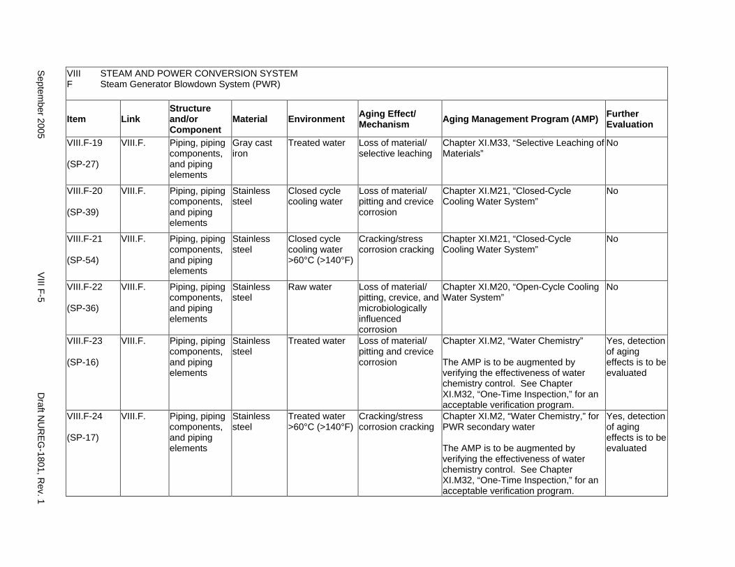
VIII STEAM AND POWER CONVERSION SYSTEM F Steam Generator Blowdown System (PWR)
Item Link Structure and/or Component
Material Environment Aging Effect/ Mechanism Aging Management Program (AMP) Further
Evaluation
VIII.F-19
(SP-27)
VIII.F. Piping, piping components, and piping elements
Gray cast iron
Treated water Loss of material/ selective leaching
Chapter XI.M33, “Selective Leaching of Materials”
No
VIII.F-20
(SP-39)
VIII.F. Piping, piping components, and piping elements
Stainless steel
Closed cycle cooling water
Loss of material/ pitting and crevice corrosion
Chapter XI.M21, “Closed-Cycle Cooling Water System”
No
VIII.F-21
(SP-54)
VIII.F. Piping, piping components, and piping elements
Stainless steel
Closed cycle cooling water >60°C (>140°F)
Cracking/stress corrosion cracking
Chapter XI.M21, “Closed-Cycle Cooling Water System”
No
VIII.F-22
(SP-36)
VIII.F. Piping, piping components, and piping elements
Stainless steel
Raw water Loss of material/ pitting, crevice, and microbiologically influenced corrosion
Chapter XI.M20, “Open-Cycle Cooling Water System”
No
VIII.F-23
(SP-16)
VIII.F. Piping, piping components, and piping elements
Stainless steel
Treated water Loss of material/ pitting and crevice corrosion
Chapter XI.M2, “Water Chemistry”
The AMP is to be augmented by verifying the effectiveness of water chemistry control. See Chapter XI.M32, “One-Time Inspection,” for an acceptable verification program.
Yes, detection of aging effects is to be evaluated
VIII.F-24
(SP-17)
VIII.F. Piping, piping components, and piping elements
Stainless steel
Treated water >60°C (>140°F)
Cracking/stress corrosion cracking
Chapter XI.M2, “Water Chemistry,” for PWR secondary water
The AMP is to be augmented by verifying the effectiveness of water chemistry control. See Chapter XI.M32, “One-Time Inspection,” for an acceptable verification program.
Yes, detection of aging effects is to be evaluated
Septem
ber 2005 V
III F-5 D
raft NU
REG
-1801, Rev. 1
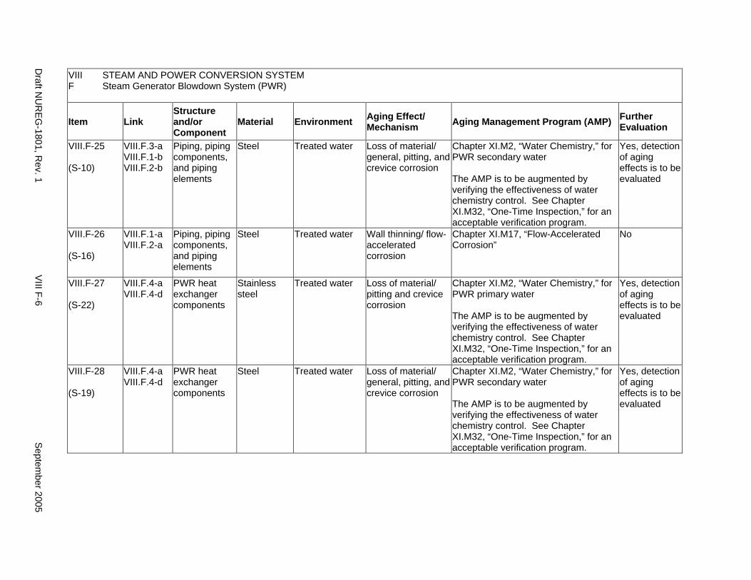
VIII STEAM AND POWER CONVERSION SYSTEM F Steam Generator Blowdown System (PWR)
Item Link Structure and/or Component
Material Environment Aging Effect/ Mechanism Aging Management Program (AMP) Further
Evaluation
VIII.F-25
(S-10)
VIII.F.3-a VIII.F.1-b VIII.F.2-b
Piping, piping components, and piping elements
Steel Treated water Loss of material/ general, pitting, and crevice corrosion
Chapter XI.M2, “Water Chemistry,” for PWR secondary water
The AMP is to be augmented by verifying the effectiveness of water chemistry control. See Chapter XI.M32, “One-Time Inspection,” for an acceptable verification program.
Yes, detection of aging effects is to be evaluated
VIII.F-26
(S-16)
VIII.F.1-a VIII.F.2-a
Piping, piping components, and piping elements
Steel Treated water Wall thinning/ flow-accelerated corrosion
Chapter XI.M17, “Flow-Accelerated Corrosion”
No
VIII.F-27
(S-22)
VIII.F.4-a VIII.F.4-d
PWR heat exchanger components
Stainless steel
Treated water Loss of material/ pitting and crevice corrosion
Chapter XI.M2, “Water Chemistry,” for PWR primary water
The AMP is to be augmented by verifying the effectiveness of water chemistry control. See Chapter XI.M32, “One-Time Inspection,” for an acceptable verification program.
Yes, detection of aging effects is to be evaluated
VIII.F-28
(S-19)
VIII.F.4-a VIII.F.4-d
PWR heat exchanger components
Steel Treated water Loss of material/ general, pitting, and crevice corrosion
Chapter XI.M2, “Water Chemistry,” for PWR secondary water
The AMP is to be augmented by verifying the effectiveness of water chemistry control. See Chapter XI.M32, “One-Time Inspection,” for an acceptable verification program.
Yes, detection of aging effects is to be evaluated
Draft N
UR
EG-1801, R
ev. 1 V
III F-6 S
eptember 2005
G. AUXILIARY FEEDWATER SYSTEM (PWR)
Systems, Structures, and Components
This section addresses the auxiliary feedwater (AFW) system for pressurized water reactors (PWRs), which extends from the condensate storage or backup water supply system to the steam generator or to the main feedwater (MFW) line. They consist of AFW piping, AFW pumps, pump turbine oil coolers, and valves, including the containment isolation valves.
Based on Regulatory Guide 1.26, “Quality Group Classifications and Standards for Water-, Steam-, and Radioactive-Waste-Containing Components of Nuclear Power Plants,” portions of the AFW system extending from the secondary side of the steam generator up to the second isolation valve and including the containment isolation valves are governed by Group B Quality Standards. In addition, portions of the AFW system that are required for their safety functions and that either do not operate during any mode of normal reactor operation or cannot be tested adequately are also governed by Group B Quality Standards. The remainder of the structures and components covered in this section are governed by Group C Quality Standards.
Pump and valve internals perform their intended functions with moving parts or with a change in configuration. They are subject to replacement based on qualified life or specified time period. Pursuant to 10 CFR 54.21(a)(1), therefore, they are not subject to an aging management review.
Aging management programs for the degradation of the external surfaces of components and miscellaneous bolting are included in VIII.H. Common miscellaneous material/environment combinations, where aging effects are not expected to degrade the ability of the structure or component to perform its intended function for the extended period of operation, are included in VIII.I.
The system piping includes all pipe sizes, including instrument piping.
System Interfaces
The systems that interface with the AFW system include the steam generator (IV.D1 and IV.D2), the main steam system (VIII.B1), the PWR feedwater system (VIII.D1), the condensate system (VIII.E), and the open- or closed-cycle cooling water systems (VII.C1 or VII.C2).
September 2005 VIII G-1 Draft NUREG-1801, Rev. 1

VIII STEAM AND POWER CONVERSION SYSTEM G Auxiliary Feedwater System (PWR)
Item Link Structure and/or Component
Material Environment Aging Effect/ Mechanism Aging Management Program (AMP) Further
Evaluation
VIII.G-1
(S-01)
VIII.G.1-e VIII.G.4-d
Buried piping, piping components, piping elements, and tanks
Steel (with or without coating or wrapping)
Soil Loss of material/ general, pitting, crevice, and microbiologically influenced corrosion
Chapter XI.M28, “Buried Piping and Tanks Surveillance,” or
Chapter XI.M34, “Buried Piping and Tanks Inspection”
No
Yes, detection of aging effects and operating experience are to be further evaluated
VIII.G-2
(S-25)
VIII.G.5-c Heat exchanger components
Stainless steel
Closed cycle cooling water
Loss of material/ pitting and crevice corrosion
Chapter XI.M21, “Closed-Cycle Cooling Water System”
No
VIII.G-3
(S-20)
VIII.G.5-d Heat exchanger components
Stainless steel
Lubricating oil Loss of material/ pitting, crevice, and microbiologically influenced corrosion
Chapter XI.M39, "Lubricating Oil Analysis"
The AMP is to be augmented by verifying the effectiveness of the lubricating oil analysis program. See Chapter XI.M32, “One-Time Inspection,” for an acceptable verification program.
Yes, detection of aging effects is to be evaluated
VIII.G-4
(S-26)
VIII.G.5-a Heat exchanger components
Stainless steel
Raw water Loss of material/ pitting, crevice, and microbiologically influenced corrosion, and fouling
Chapter XI.M20, “Open-Cycle Cooling Water System”
No
VIII.G-5
(S-23)
VIII.G.5-c Heat exchanger components
Steel Closed cycle cooling water
Loss of material/ general, pitting, crevice, and galvanic corrosion
Chapter XI.M21, “Closed-Cycle Cooling Water System”
No
Draft N
UR
EG-1801, R
ev. 1 V
III G-2
Septem
ber 2005
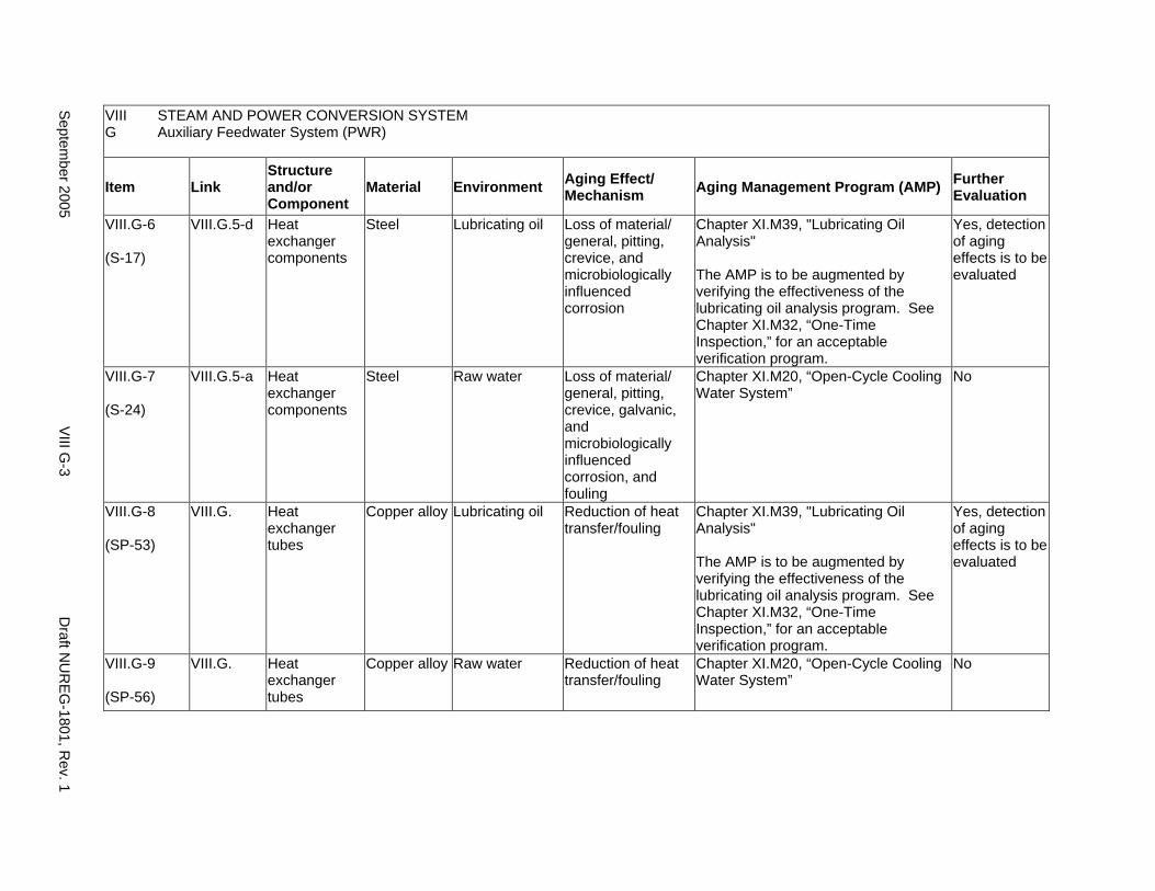
VIII STEAM AND POWER CONVERSION SYSTEM G Auxiliary Feedwater System (PWR)
Item Link Structure and/or Component
Material Environment Aging Effect/ Mechanism Aging Management Program (AMP) Further
Evaluation
VIII.G-6
(S-17)
VIII.G.5-d Heat exchanger components
Steel Lubricating oil Loss of material/ general, pitting, crevice, and microbiologically influenced corrosion
Chapter XI.M39, "Lubricating Oil Analysis"
The AMP is to be augmented by verifying the effectiveness of the lubricating oil analysis program. See Chapter XI.M32, “One-Time Inspection,” for an acceptable verification program.
Yes, detection of aging effects is to be evaluated
VIII.G-7
(S-24)
VIII.G.5-a Heat exchanger components
Steel Raw water Loss of material/ general, pitting, crevice, galvanic, and microbiologically influenced corrosion, and fouling
Chapter XI.M20, “Open-Cycle Cooling Water System”
No
VIII.G-8
(SP-53)
VIII.G. Heat exchanger tubes
Copper alloy Lubricating oil Reduction of heat transfer/fouling
Chapter XI.M39, "Lubricating Oil Analysis"
The AMP is to be augmented by verifying the effectiveness of the lubricating oil analysis program. See Chapter XI.M32, “One-Time Inspection,” for an acceptable verification program.
Yes, detection of aging effects is to be evaluated
VIII.G-9
(SP-56)
VIII.G. Heat exchanger tubes
Copper alloy Raw water Reduction of heat transfer/fouling
Chapter XI.M20, “Open-Cycle Cooling Water System”
No
Septem
ber 2005 V
III G-3
Draft N
UR
EG-1801, R
ev. 1
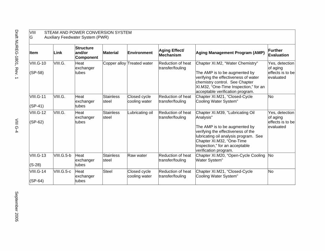
VIII STEAM AND POWER CONVERSION SYSTEM G Auxiliary Feedwater System (PWR)
Item Link Structure and/or Component
Material Environment Aging Effect/ Mechanism Aging Management Program (AMP) Further
Evaluation
VIII.G-10
(SP-58)
VIII.G. Heat exchanger tubes
Copper alloy Treated water Reduction of heat transfer/fouling
Chapter XI.M2, “Water Chemistry”
The AMP is to be augmented by verifying the effectiveness of water chemistry control. See Chapter XI.M32, “One-Time Inspection,” for an acceptable verification program.
Yes, detection of aging effects is to be evaluated
VIII.G-11
(SP-41)
VIII.G. Heat exchanger tubes
Stainless steel
Closed cycle cooling water
Reduction of heat transfer/fouling
Chapter XI.M21, “Closed-Cycle Cooling Water System”
No
VIII.G-12
(SP-62)
VIII.G. Heat exchanger tubes
Stainless steel
Lubricating oil Reduction of heat transfer/fouling
Chapter XI.M39, "Lubricating Oil Analysis"
The AMP is to be augmented by verifying the effectiveness of the lubricating oil analysis program. See Chapter XI.M32, “One-Time Inspection,” for an acceptable verification program.
Yes, detection of aging effects is to be evaluated
VIII.G-13
(S-28)
VIII.G.5-b Heat exchanger tubes
Stainless steel
Raw water Reduction of heat transfer/fouling
Chapter XI.M20, “Open-Cycle Cooling Water System”
No
VIII.G-14
(SP-64)
VIII.G.5-c Heat exchanger tubes
Steel Closed cycle cooling water
Reduction of heat transfer/fouling
Chapter XI.M21, “Closed-Cycle Cooling Water System”
No
Draft N
UR
EG-1801, R
ev. 1 V
III G-4
Septem
ber 2005

VIII STEAM AND POWER CONVERSION SYSTEM G Auxiliary Feedwater System (PWR)
Item Link Structure and/or Component
Material Environment Aging Effect/ Mechanism Aging Management Program (AMP) Further
Evaluation
VIII.G-15
(SP-63)
VIII.G. Heat exchanger tubes
Steel Lubricating oil Reduction of heat transfer/fouling
Chapter XI.M39, "Lubricating Oil Analysis"
The AMP is to be augmented by verifying the effectiveness of the lubricating oil analysis program. See Chapter XI.M32, “One-Time Inspection,” for an acceptable verification program.
Yes, detection of aging effects is to be evaluated
VIII.G-16
(S-27)
VIII.G.5-b Heat exchanger tubes
Steel Raw water Reduction of heat transfer/fouling
Chapter XI.M20, “Open-Cycle Cooling Water System”
No
VIII.G-17
(SP-24)
VIII.G. Piping, piping components, and piping elements
Aluminum Treated water Loss of material/ pitting and crevice corrosion
Chapter XI.M2, "Water Chemistry"
The AMP is to be augmented by verifying the effectiveness of water chemistry control. See Chapter XI.M32, “One-Time Inspection,” for an acceptable verification program.
Yes, detection of aging effects is to be evaluated
VIII.G-18
(SP-8)
VIII.G. Piping, piping components, and piping elements
Copper alloy Closed cycle cooling water
Loss of material/ pitting, crevice, and galvanic corrosion
Chapter XI.M21, “Closed-Cycle Cooling Water System”
No
VIII.G-19
(SP-32)
VIII.G. Piping, piping components, and piping elements
Copper alloy Lubricating oil Loss of material/ pitting and crevice corrosion
Chapter XI.M39, "Lubricating Oil Analysis"
The AMP is to be augmented by verifying the effectiveness of the lubricating oil analysis program. See Chapter XI.M32, “One-Time Inspection,” for an acceptable verification program.
Yes, detection of aging effects is to be evaluated
Septem
ber 2005 V
III G-5
Draft N
UR
EG-1801, R
ev. 1
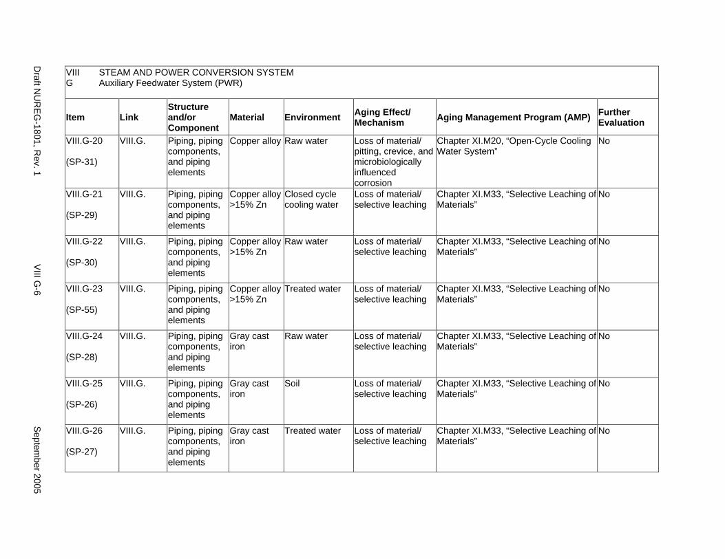
VIII STEAM AND POWER CONVERSION SYSTEM G Auxiliary Feedwater System (PWR)
Item Link Structure and/or Component
Material Environment Aging Effect/ Mechanism Aging Management Program (AMP) Further
Evaluation
VIII.G-20
(SP-31)
VIII.G. Piping, piping components, and piping elements
Copper alloy Raw water Loss of material/ pitting, crevice, and microbiologically influenced corrosion
Chapter XI.M20, “Open-Cycle Cooling Water System”
No
VIII.G-21
(SP-29)
VIII.G. Piping, piping components, and piping elements
Copper alloy >15% Zn
Closed cycle cooling water
Loss of material/ selective leaching
Chapter XI.M33, “Selective Leaching of Materials”
No
VIII.G-22
(SP-30)
VIII.G. Piping, piping components, and piping elements
Copper alloy >15% Zn
Raw water Loss of material/ selective leaching
Chapter XI.M33, “Selective Leaching of Materials”
No
VIII.G-23
(SP-55)
VIII.G. Piping, piping components, and piping elements
Copper alloy >15% Zn
Treated water Loss of material/ selective leaching
Chapter XI.M33, “Selective Leaching of Materials”
No
VIII.G-24
(SP-28)
VIII.G. Piping, piping components, and piping elements
Gray cast iron
Raw water Loss of material/ selective leaching
Chapter XI.M33, “Selective Leaching of Materials”
No
VIII.G-25
(SP-26)
VIII.G. Piping, piping components, and piping elements
Gray cast iron
Soil Loss of material/ selective leaching
Chapter XI.M33, “Selective Leaching of Materials"
No
VIII.G-26
(SP-27)
VIII.G. Piping, piping components, and piping elements
Gray cast iron
Treated water Loss of material/ selective leaching
Chapter XI.M33, “Selective Leaching of Materials”
No
Draft N
UR
EG-1801, R
ev. 1 V
III G-6
Septem
ber 2005
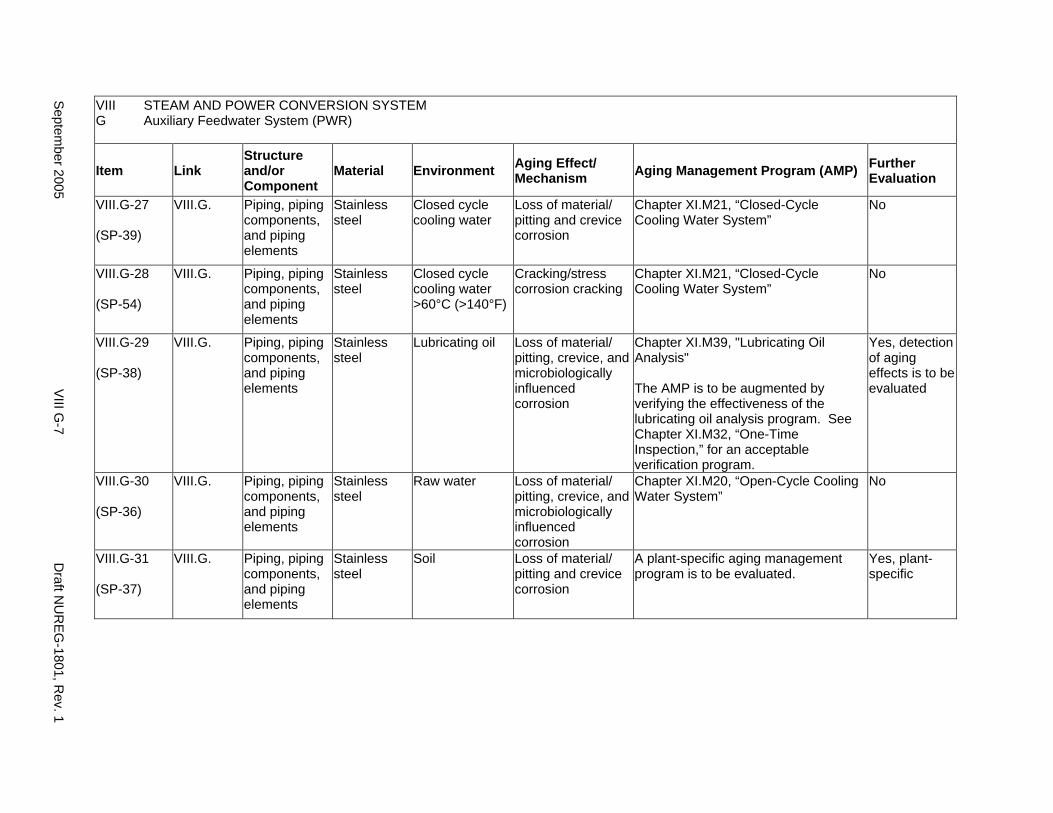
VIII STEAM AND POWER CONVERSION SYSTEM G Auxiliary Feedwater System (PWR)
Item Link Structure and/or Component
Material Environment Aging Effect/ Mechanism Aging Management Program (AMP) Further
Evaluation
VIII.G-27
(SP-39)
VIII.G. Piping, piping components, and piping elements
Stainless steel
Closed cycle cooling water
Loss of material/ pitting and crevice corrosion
Chapter XI.M21, “Closed-Cycle Cooling Water System”
No
VIII.G-28
(SP-54)
VIII.G. Piping, piping components, and piping elements
Stainless steel
Closed cycle cooling water >60°C (>140°F)
Cracking/stress corrosion cracking
Chapter XI.M21, “Closed-Cycle Cooling Water System”
No
VIII.G-29
(SP-38)
VIII.G. Piping, piping components, and piping elements
Stainless steel
Lubricating oil Loss of material/ pitting, crevice, and microbiologically influenced corrosion
Chapter XI.M39, "Lubricating Oil Analysis"
The AMP is to be augmented by verifying the effectiveness of the lubricating oil analysis program. See Chapter XI.M32, “One-Time Inspection,” for an acceptable verification program.
Yes, detection of aging effects is to be evaluated
VIII.G-30
(SP-36)
VIII.G. Piping, piping components, and piping elements
Stainless steel
Raw water Loss of material/ pitting, crevice, and microbiologically influenced corrosion
Chapter XI.M20, “Open-Cycle Cooling Water System”
No
VIII.G-31
(SP-37)
VIII.G. Piping, piping components, and piping elements
Stainless steel
Soil Loss of material/ pitting and crevice corrosion
A plant-specific aging management program is to be evaluated.
Yes, plant-specific
Septem
ber 2005 V
III G-7
Draft N
UR
EG-1801, R
ev. 1
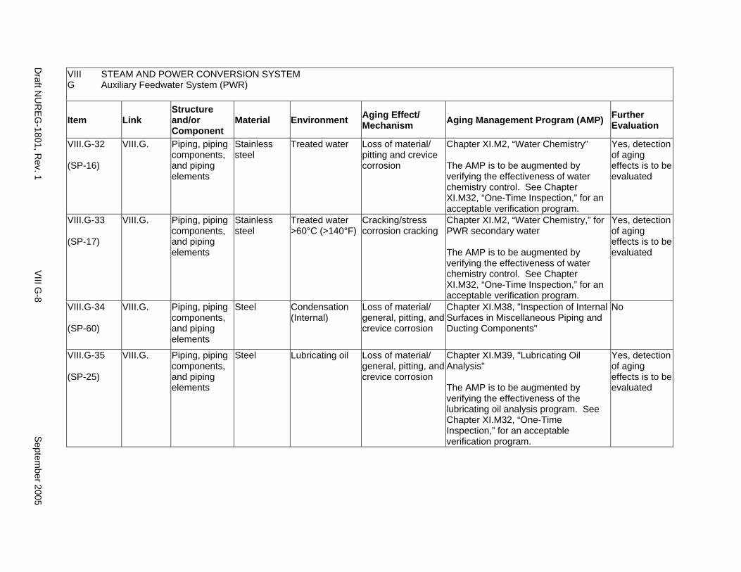
VIII STEAM AND POWER CONVERSION SYSTEM G Auxiliary Feedwater System (PWR)
Item Link Structure and/or Component
Material Environment Aging Effect/ Mechanism Aging Management Program (AMP) Further
Evaluation
VIII.G-32
(SP-16)
VIII.G. Piping, piping components, and piping elements
Stainless steel
Treated water Loss of material/ pitting and crevice corrosion
Chapter XI.M2, “Water Chemistry”
The AMP is to be augmented by verifying the effectiveness of water chemistry control. See Chapter XI.M32, “One-Time Inspection,” for an acceptable verification program.
Yes, detection of aging effects is to be evaluated
VIII.G-33
(SP-17)
VIII.G. Piping, piping components, and piping elements
Stainless steel
Treated water >60°C (>140°F)
Cracking/stress corrosion cracking
Chapter XI.M2, “Water Chemistry,” for PWR secondary water
The AMP is to be augmented by verifying the effectiveness of water chemistry control. See Chapter XI.M32, “One-Time Inspection,” for an acceptable verification program.
Yes, detection of aging effects is to be evaluated
VIII.G-34
(SP-60)
VIII.G. Piping, piping components, and piping elements
Steel Condensation (Internal)
Loss of material/ general, pitting, and crevice corrosion
Chapter XI.M38, "Inspection of Internal Surfaces in Miscellaneous Piping and Ducting Components"
No
VIII.G-35
(SP-25)
VIII.G. Piping, piping components, and piping elements
Steel Lubricating oil Loss of material/ general, pitting, and crevice corrosion
Chapter XI.M39, "Lubricating Oil Analysis"
The AMP is to be augmented by verifying the effectiveness of the lubricating oil analysis program. See Chapter XI.M32, “One-Time Inspection,” for an acceptable verification program.
Yes, detection of aging effects is to be evaluated
Draft N
UR
EG-1801, R
ev. 1 V
III G-8
Septem
ber 2005
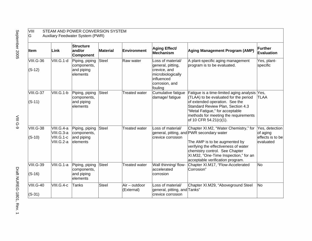
VIII STEAM AND POWER CONVERSION SYSTEM G Auxiliary Feedwater System (PWR)
Item Link Structure and/or Component
Material Environment Aging Effect/ Mechanism Aging Management Program (AMP) Further
Evaluation
VIII.G-36
(S-12)
VIII.G.1-d Piping, piping components, and piping elements
Steel Raw water Loss of material/ general, pitting, crevice, and microbiologically influenced corrosion, and fouling
A plant-specific aging management program is to be evaluated.
Yes, plant-specific
VIII.G-37
(S-11)
VIII.G.1-b Piping, piping components, and piping elements
Steel Treated water Cumulative fatigue damage/ fatigue
Fatigue is a time-limited aging analysis (TLAA) to be evaluated for the period of extended operation. See the Standard Review Plan, Section 4.3 “Metal Fatigue,” for acceptable methods for meeting the requirements of 10 CFR 54.21(c)(1).
Yes, TLAA
VIII.G-38
(S-10)
VIII.G.4-a VIII.G.3-a VIII.G.1-c VIII.G.2-a
Piping, piping components, and piping elements
Steel Treated water Loss of material/ general, pitting, and crevice corrosion
Chapter XI.M2, “Water Chemistry,” for PWR secondary water
The AMP is to be augmented by verifying the effectiveness of water chemistry control. See Chapter XI.M32, “One-Time Inspection,” for an acceptable verification program.
Yes, detection of aging effects is to be evaluated
VIII.G-39
(S-16)
VIII.G.1-a Piping, piping components, and piping elements
Steel Treated water Wall thinning/ flow-accelerated corrosion
Chapter XI.M17, “Flow-Accelerated Corrosion”
No
VIII.G-40
(S-31)
VIII.G.4-c Tanks Steel Air – outdoor (External)
Loss of material/ general, pitting, and crevice corrosion
Chapter XI.M29, “Aboveground Steel Tanks”
No
Septem
ber 2005 V
III G-9
Draft N
UR
EG-1801, R
ev. 1
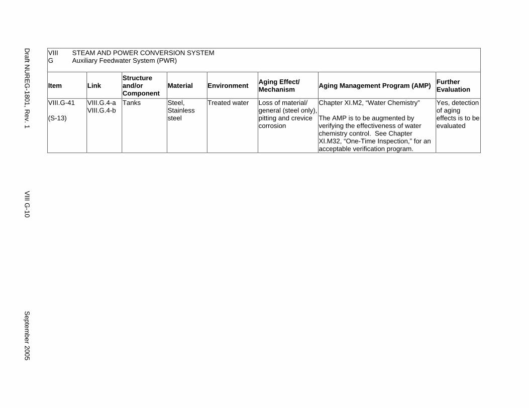
VIII STEAM AND POWER CONVERSION SYSTEM G Auxiliary Feedwater System (PWR)
Item Link Structure and/or Component
Material Environment Aging Effect/ Mechanism Aging Management Program (AMP) Further
Evaluation
VIII.G-41
(S-13)
VIII.G.4-a VIII.G.4-b
Tanks Steel, Stainless steel
Treated water Loss of material/ general (steel only), pitting and crevice corrosion
Chapter XI.M2, “Water Chemistry”
The AMP is to be augmented by verifying the effectiveness of water chemistry control. See Chapter XI.M32, “One-Time Inspection,” for an acceptable verification program.
Yes, detection of aging effects is to be evaluated
Draft N
UR
EG-1801, R
ev. 1 V
III G-10
Septem
ber 2005
H. EXTERNAL SURFACES OF COMPONENTS AND MISCELLANEOUS BOLTING
Systems, Structures, and Components
This section includes the aging management programs for the degradation of external surfaces of all steel structures and components, including closure bolting in the steam and power conversion system in pressurized water reactors (PWRs) and boiling water reactors (BWRs). For the steel components in PWRs, this section addresses only boric acid corrosion of external surfaces as a result of dripping borated water leaking from an adjacent PWR component.
System Interfaces
The structures and components covered in this section belong to the Steam and Power Conversion Systems in PWRs and BWRs (for example, see system interfaces in VIII.A to VIII.G for details).
September 2005 VIII H-1 Draft NUREG-1801, Rev. 1
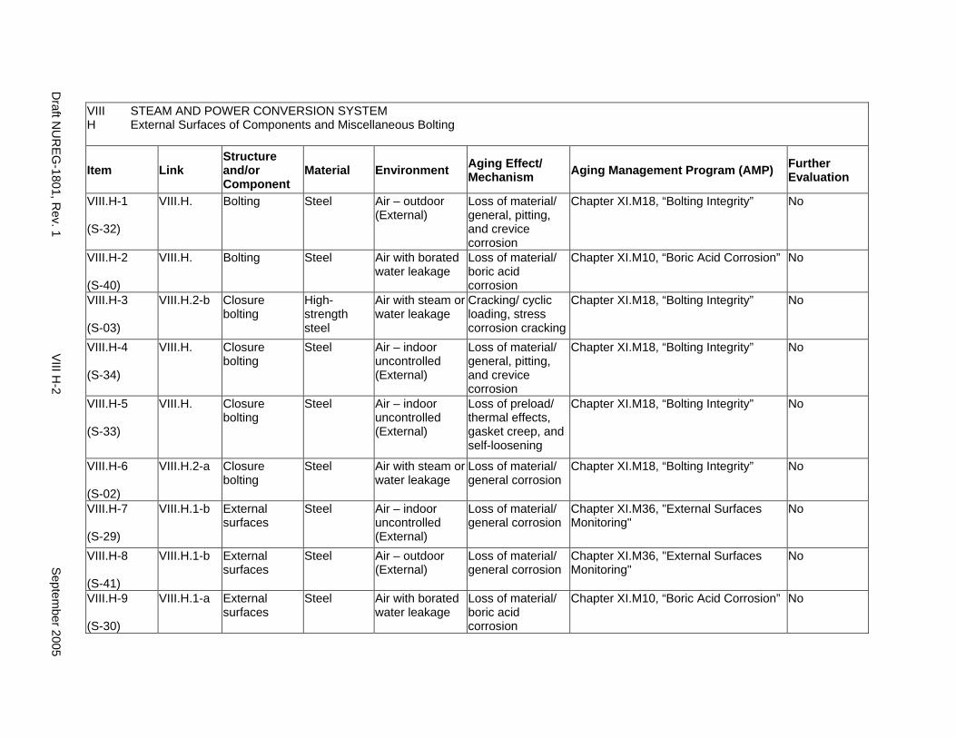
VIII STEAM AND POWER CONVERSION SYSTEM H External Surfaces of Components and Miscellaneous Bolting
Item Link Structure and/or Component
Material Environment Aging Effect/ Mechanism Aging Management Program (AMP) Further
Evaluation
VIII.H-1
(S-32)
VIII.H. Bolting Steel Air – outdoor (External)
Loss of material/ general, pitting, and crevice corrosion
Chapter XI.M18, “Bolting Integrity” No
VIII.H-2
(S-40)
VIII.H. Bolting Steel Air with borated water leakage
Loss of material/ boric acid corrosion
Chapter XI.M10, “Boric Acid Corrosion” No
VIII.H-3
(S-03)
VIII.H.2-b Closure bolting
High-strength steel
Air with steam or water leakage
Cracking/ cyclic loading, stress corrosion cracking
Chapter XI.M18, “Bolting Integrity” No
VIII.H-4
(S-34)
VIII.H. Closure bolting
Steel Air – indoor uncontrolled (External)
Loss of material/ general, pitting, and crevice corrosion
Chapter XI.M18, “Bolting Integrity” No
VIII.H-5
(S-33)
VIII.H. Closure bolting
Steel Air – indoor uncontrolled (External)
Loss of preload/ thermal effects, gasket creep, and self-loosening
Chapter XI.M18, “Bolting Integrity” No
VIII.H-6
(S-02)
VIII.H.2-a Closure bolting
Steel Air with steam or water leakage
Loss of material/ general corrosion
Chapter XI.M18, “Bolting Integrity” No
VIII.H-7
(S-29)
VIII.H.1-b External surfaces
Steel Air – indoor uncontrolled (External)
Loss of material/ general corrosion
Chapter XI.M36, "External Surfaces Monitoring"
No
VIII.H-8
(S-41)
VIII.H.1-b External surfaces
Steel Air – outdoor (External)
Loss of material/ general corrosion
Chapter XI.M36, "External Surfaces Monitoring"
No
VIII.H-9
(S-30)
VIII.H.1-a External surfaces
Steel Air with borated water leakage
Loss of material/ boric acid corrosion
Chapter XI.M10, “Boric Acid Corrosion” No
Draft N
UR
EG-1801, R
ev. 1 V
III H-2
Septem
ber 2005
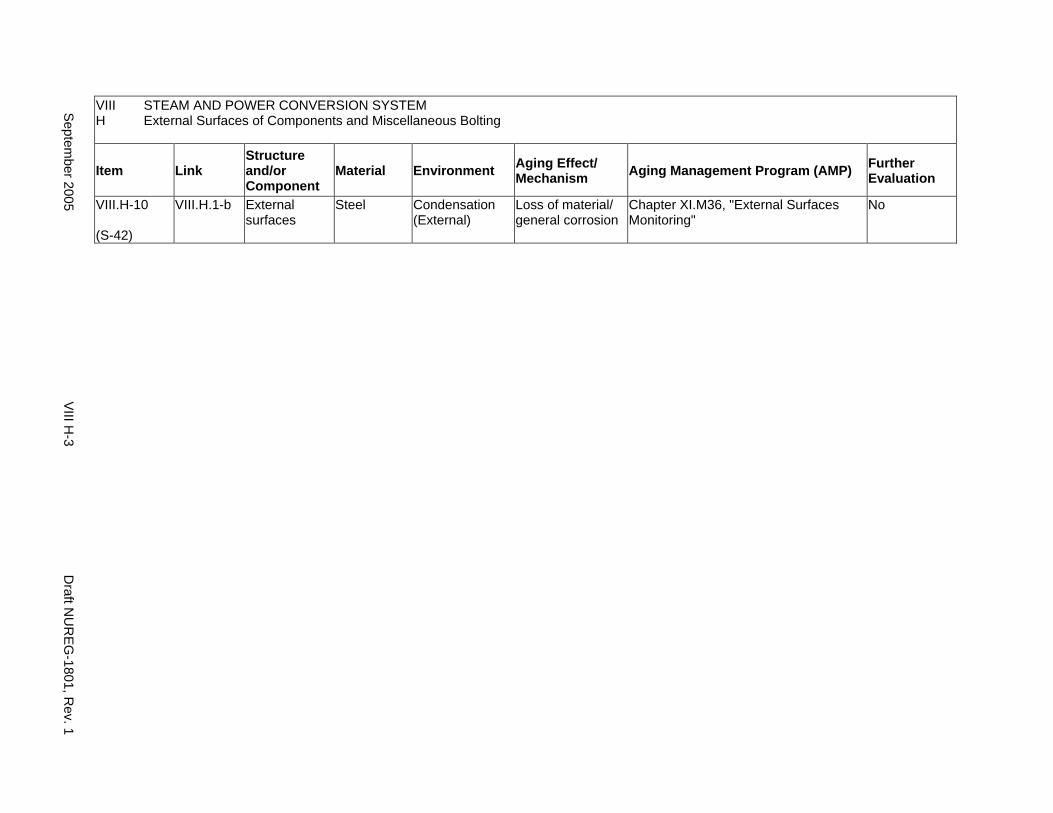
VIII STEAM AND POWER CONVERSION SYSTEM H External Surfaces of Components and Miscellaneous Bolting
Item Link Structure and/or Component
Material Environment Aging Effect/ Mechanism Aging Management Program (AMP) Further
Evaluation
VIII.H-10
(S-42)
VIII.H.1-b External surfaces
Steel Condensation (External)
Loss of material/ general corrosion
Chapter XI.M36, "External Surfaces Monitoring"
No
Septem
ber 2005 VIII H
-3 D
raft NU
REG
-1801, Rev. 1

This Page Intentionally Left Blank
Draft NUREG-1801, Rev. 1 VIII H-4 September 2005
I. COMMON MISCELLANEOUS MATERIAL/ENVIRONMENT COMBINATIONS
Systems, Structures, and Components
This section includes the aging management programs for miscellaneous material/environment combinations which may be found throughout the steam and power conversion system’s structures and components. For the material/environment combinations in this part, aging effects are not expected to degrade the ability of the structure or component to perform its intended function for the extended period of operation.Therefore, no resulting aging management programs for these structures and components are required.
System Interfaces
The structures and components covered in this section belong to the steam and power conversion system in pressurized water reactors (PWRs) and boiling water reactors (BWRs) (For example, see system interfaces in VIII.A to VIII.D2 for details).
September 2005 VIII I-1 Draft NUREG-1801, Rev. 1
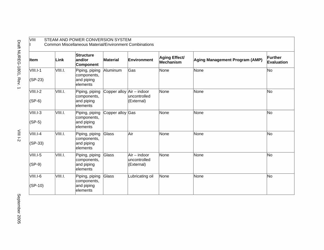
VIII STEAM AND POWER CONVERSION SYSTEM I Common Miscellaneous Material/Environment Combinations
Item Link Structure and/or Component
Material Environment Aging Effect/ Mechanism Aging Management Program (AMP) Further
Evaluation
VIII.I-1
(SP-23)
VIII.I. Piping, piping components, and piping elements
Aluminum Gas None None No
VIII.I-2
(SP-6)
VIII.I. Piping, piping components, and piping elements
Copper alloy Air – indoor uncontrolled (External)
None None No
VIII.I-3
(SP-5)
VIII.I. Piping, piping components, and piping elements
Copper alloy Gas None None No
VIII.I-4
(SP-33)
VIII.I. Piping, piping components, and piping elements
Glass Air None None No
VIII.I-5
(SP-9)
VIII.I. Piping, piping components, and piping elements
Glass Air – indoor uncontrolled (External)
None None No
VIII.I-6
(SP-10)
VIII.I. Piping, piping components, and piping elements
Glass Lubricating oil None None No
Draft N
UR
EG-1801, R
ev. 1 V
III I-2 S
eptember 2005

VIII STEAM AND POWER CONVERSION SYSTEM I Common Miscellaneous Material/Environment Combinations
Item Link Structure and/or Component
Material Environment Aging Effect/ Mechanism Aging Management Program (AMP) Further
Evaluation
VIII.I-7
(SP-34)
VIII.I. Piping, piping components, and piping elements
Glass Raw water None None No
VIII.I-8
(SP-35)
VIII.I. Piping, piping components, and piping elements
Glass Treated water None None No
VIII.I-9
(SP-11)
VIII.I. Piping, piping components, and piping elements
Nickel alloy Air – indoor uncontrolled (External)
None None No
VIII.I-10
(SP-12)
VIII.I. Piping, piping components, and piping elements
Stainless steel
Air – indoor uncontrolled (External)
None None No
VIII.I-11
(SP-13)
VIII.I. Piping, piping components, and piping elements
Stainless steel
Concrete None None No
VIII.I-12
(SP-15)
VIII.I. Piping, piping components, and piping elements
Stainless steel
Gas None None No
Septem
ber 2005 V
III I-3 D
raft NU
REG
-1801, Rev. 1
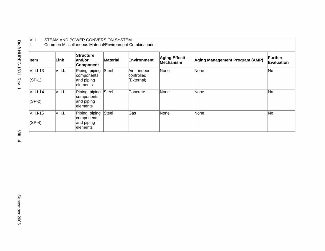
VIII STEAM AND POWER CONVERSION SYSTEM I Common Miscellaneous Material/Environment Combinations
Item Link Structure and/or Component
Material Environment Aging Effect/ Mechanism Aging Management Program (AMP) Further
Evaluation
VIII.I-13
(SP-1)
VIII.I. Piping, piping components, and piping elements
Steel Air – indoor controlled (External)
None None No
VIII.I-14
(SP-2)
VIII.I. Piping, piping components, and piping elements
Steel Concrete None None No
VIII.I-15
(SP-4)
VIII.I. Piping, piping components, and piping elements
Steel Gas None None No
Draft N
UR
EG-1801, R
ev. 1 V
III I-4 S
eptember 2005
CHAPTER IX
SELECTED DEFINITIONS AND USE OF TERMS FOR
STRUCTURES, COMPONENTS, MATERIALS, ENVIRONMENTS,
AGING EFFECTS, AND AGING MECHANISMS
September 2005 IX-i Draft NUREG-1801, Rev. 1
This Page Intentionally Left Blank
Draft NUREG-1801, Rev. 1 IX-ii September 2005
SELECTED DEFINITIONS and USE OF TERMS FOR DESCRIBING AND STANDARDIZING STRUCTURES, COMPONENTS, MATERIALS, ENVIRONMENTS, AGING EFFECTS, AND AGING MECHANISMS
A. Introduction
B. Structures and Components
C. Materials
D. Environments
E. Aging Effects
F. Aging Mechanisms
G. References
September 2005 IX-1 Draft NUREG-1801, Rev. 1
A. Introduction
The format and content of the aging management review (AMR) tables presented here in the GALL Report, Vol. 2, (GALL’05) have been revised to enhance its applicability to future plant license renewal applications. Several types of changes were incorporated in this revision to achieve the objective. One of these was to add material, environment, aging effect and program (MEAP) combinations established by precedents establishing strong technical justification from earlier license renewal applications (LRAs) and the corresponding NRC safety evaluation reports (SERs).
Associated with this was the simplification and generalization of terms used within these MEAP combinations to make the line items more generic and less prescriptive. As a simple example, the phrase " Piping, piping components, and piping elements" is used to replace various combinations of “piping, fittings, tubing, flow elements/indicators, demineralizer, nozzles, orifices, flex hoses, pump casing and bowl, safe ends, sight glasses, spray head, strainers, thermowells, and valve body and bonnet."
Further associated with this simplification is the need to define, here in this new chapter IX, and further in NUREG-1833, Technical Bases for Revision to the License Renewal Guidance Documents (“Bases Document”), what these simplified terms mean and how and where they are used, and what parameters in GALL’01, they have replaced. The following tables define some of the simplified terms used in the preceding GALL AMR tables in Chapters II, III, IV, V, VI, VII, and VIII, of this document. An electronic version of this GALL’05, is available in which each expression defined in these tables is linked to the specific chapters in the GALL report where they occur. A complete listing of the unique identifiers and their locations of usage in the revised GALL Report is found in Appendix A of the Bases Document, accompanying the 2005 revision of the license renewal guidance documents.
B. Structures and Components
The GALL Report does not address scoping of structures and components for license renewal. Scoping is plant-specific, and the results depend on individual plant design and its current licensing basis. The inclusion of a certain structure or component in the GALL Report does not mean that this particular structure or component is within the scope of license renewal for all plants. Conversely, the omission of a certain structure or component in the GALL Report does not mean that this particular structure or component is omitted from the scope of license renewal for any plant.
Draft NUREG-1801, Rev. 1 IX-2 September 2005
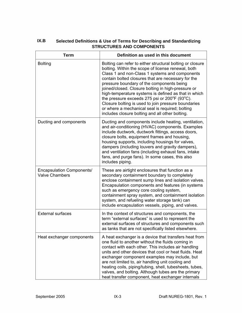
IX.B Selected Definitions & Use of Terms for Describing and Standardizing STRUCTURES AND COMPONENTS
Term Definition as used in this document
Bolting Bolting can refer to either structural bolting or closure bolting. Within the scope of license renewal, both Class 1 and non-Class 1 systems and components contain bolted closures that are necessary for the pressure boundary of the components being joined/closed. Closure bolting in high-pressure or high-temperature systems is defined as that in which the pressure exceeds 275 psi or 200oF (93oC). Closure bolting is used to join pressure boundaries or where a mechanical seal is required; bolting includes closure bolting and all other bolting.
Ducting and components Ducting and components include heating, ventilation, and air-conditioning (HVAC) components. Examples include ductwork, ductwork fittings, access doors, closure bolts, equipment frames and housing, housing supports, including housings for valves, dampers (including louvers and gravity dampers), and ventilation fans (including exhaust fans, intake fans, and purge fans). In some cases, this also includes piping.
Encapsulation Components/ Valve Chambers
These are airtight enclosures that function as a secondary containment boundary to completely enclose containment sump lines and isolation valves. Encapsulation components and features (in systems such as emergency core cooling system, containment spray system, and containment isolation system, and refueling water storage tank) can include encapsulation vessels, piping, and valves.
External surfaces In the context of structures and components, the term “external surfaces” is used to represent the external surfaces of structures and components such as tanks that are not specifically listed elsewhere.
Heat exchanger components A heat exchanger is a device that transfers heat from one fluid to another without the fluids coming in contact with each other. This includes air handling units and other devices that cool or heat fluids. Heat exchanger component examples may include, but are not limited to, air handling unit cooling and heating coils, piping/tubing, shell, tubesheets, tubes, valves, and bolting. Although tubes are the primary heat transfer component, heat exchanger internals
September 2005 IX-3 Draft NUREG-1801, Rev. 1
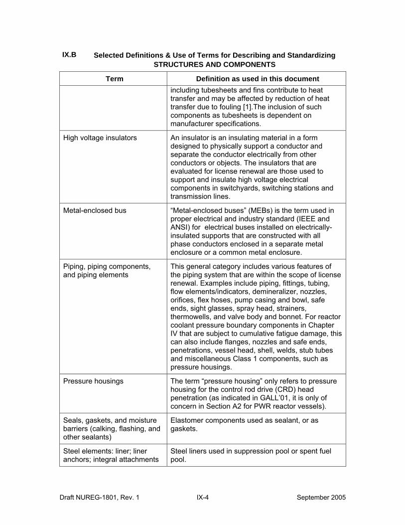
IX.B Selected Definitions & Use of Terms for Describing and Standardizing STRUCTURES AND COMPONENTS
Term Definition as used in this document including tubesheets and fins contribute to heat transfer and may be affected by reduction of heat transfer due to fouling [1].The inclusion of such components as tubesheets is dependent on manufacturer specifications.
High voltage insulators An insulator is an insulating material in a form designed to physically support a conductor and separate the conductor electrically from other conductors or objects. The insulators that are evaluated for license renewal are those used to support and insulate high voltage electrical components in switchyards, switching stations and transmission lines.
Metal-enclosed bus “Metal-enclosed buses” (MEBs) is the term used in proper electrical and industry standard (IEEE and ANSI) for electrical buses installed on electrically-insulated supports that are constructed with all phase conductors enclosed in a separate metal enclosure or a common metal enclosure.
Piping, piping components, and piping elements
This general category includes various features of the piping system that are within the scope of license renewal. Examples include piping, fittings, tubing, flow elements/indicators, demineralizer, nozzles, orifices, flex hoses, pump casing and bowl, safe ends, sight glasses, spray head, strainers, thermowells, and valve body and bonnet. For reactor coolant pressure boundary components in Chapter IV that are subject to cumulative fatigue damage, this can also include flanges, nozzles and safe ends, penetrations, vessel head, shell, welds, stub tubes and miscellaneous Class 1 components, such as pressure housings.
Pressure housings The term “pressure housing” only refers to pressure housing for the control rod drive (CRD) head penetration (as indicated in GALL’01, it is only of concern in Section A2 for PWR reactor vessels).
Seals, gaskets, and moisture barriers (calking, flashing, and other sealants)
Elastomer components used as sealant, or as gaskets.
Steel elements: liner; liner anchors; integral attachments
Steel liners used in suppression pool or spent fuel pool.
Draft NUREG-1801, Rev. 1 IX-4 September 2005
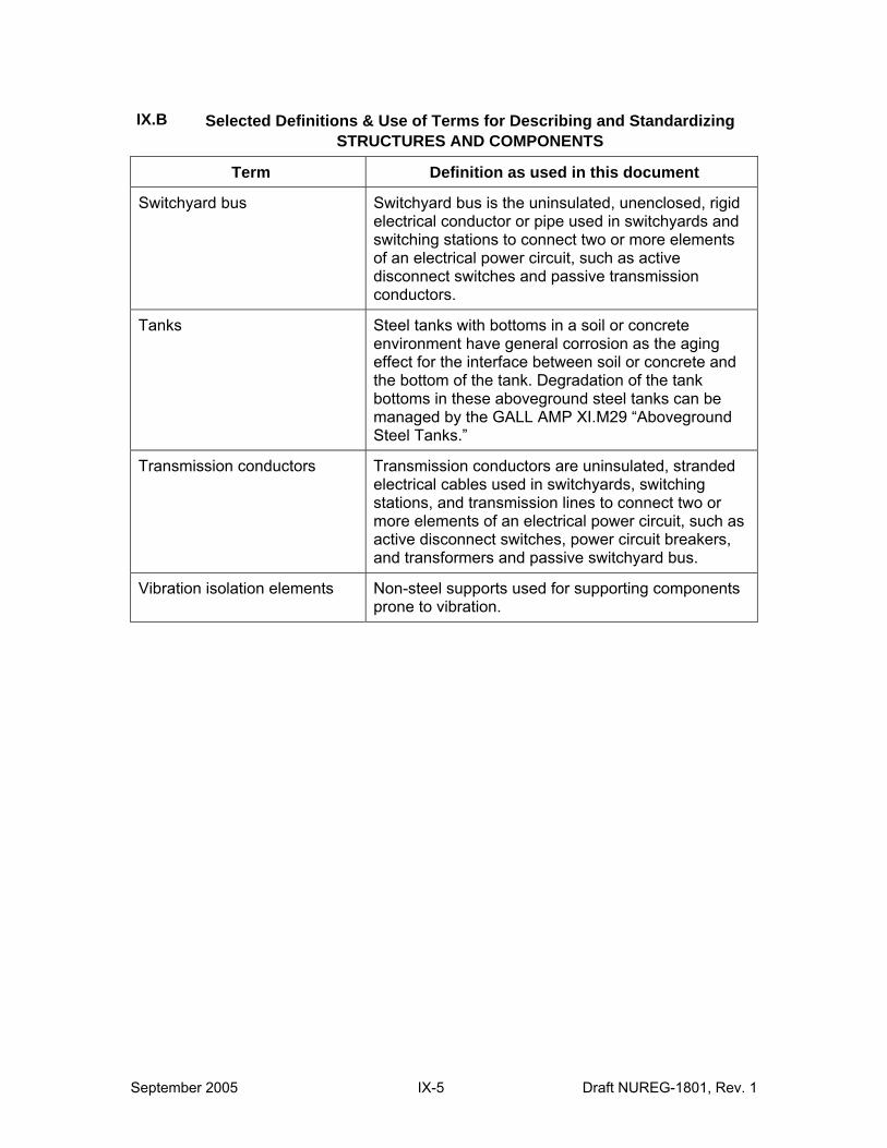
IX.B Selected Definitions & Use of Terms for Describing and Standardizing STRUCTURES AND COMPONENTS
Term Definition as used in this document
Switchyard bus Switchyard bus is the uninsulated, unenclosed, rigid electrical conductor or pipe used in switchyards and switching stations to connect two or more elements of an electrical power circuit, such as active disconnect switches and passive transmission conductors.
Tanks Steel tanks with bottoms in a soil or concrete environment have general corrosion as the aging effect for the interface between soil or concrete and the bottom of the tank. Degradation of the tank bottoms in these aboveground steel tanks can be managed by the GALL AMP XI.M29 “Aboveground Steel Tanks.”
Transmission conductors Transmission conductors are uninsulated, stranded electrical cables used in switchyards, switching stations, and transmission lines to connect two or more elements of an electrical power circuit, such as active disconnect switches, power circuit breakers, and transformers and passive switchyard bus.
Vibration isolation elements Non-steel supports used for supporting components prone to vibration.
September 2005 IX-5 Draft NUREG-1801, Rev. 1
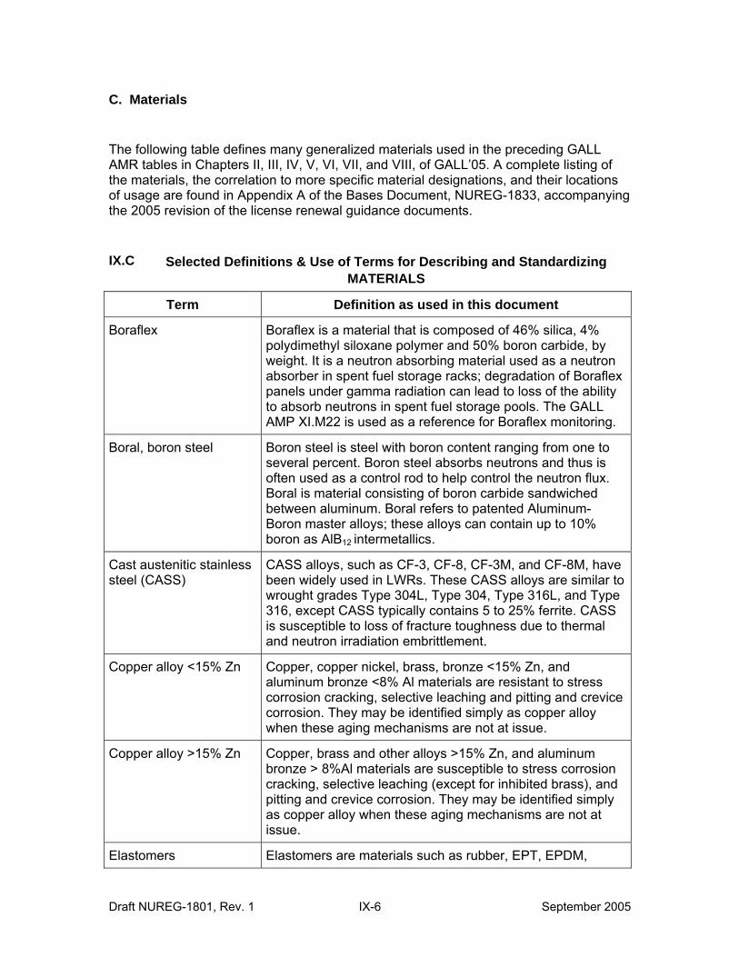
C. Materials
The following table defines many generalized materials used in the preceding GALL AMR tables in Chapters II, III, IV, V, VI, VII, and VIII, of GALL’05. A complete listing of the materials, the correlation to more specific material designations, and their locations of usage are found in Appendix A of the Bases Document, NUREG-1833, accompanying the 2005 revision of the license renewal guidance documents.
IX.C Selected Definitions & Use of Terms for Describing and Standardizing MATERIALS
Term Definition as used in this document
Boraflex Boraflex is a material that is composed of 46% silica, 4% polydimethyl siloxane polymer and 50% boron carbide, by weight. It is a neutron absorbing material used as a neutron absorber in spent fuel storage racks; degradation of Boraflex panels under gamma radiation can lead to loss of the ability to absorb neutrons in spent fuel storage pools. The GALL AMP XI.M22 is used as a reference for Boraflex monitoring.
Boral, boron steel Boron steel is steel with boron content ranging from one to several percent. Boron steel absorbs neutrons and thus is often used as a control rod to help control the neutron flux. Boral is material consisting of boron carbide sandwiched between aluminum. Boral refers to patented Aluminum-Boron master alloys; these alloys can contain up to 10% boron as AlB12 intermetallics.
Cast austenitic stainless steel (CASS)
CASS alloys, such as CF-3, CF-8, CF-3M, and CF-8M, have been widely used in LWRs. These CASS alloys are similar to wrought grades Type 304L, Type 304, Type 316L, and Type 316, except CASS typically contains 5 to 25% ferrite. CASS is susceptible to loss of fracture toughness due to thermal and neutron irradiation embrittlement.
Copper alloy <15% Zn Copper, copper nickel, brass, bronze <15% Zn, and aluminum bronze <8% Al materials are resistant to stress corrosion cracking, selective leaching and pitting and crevice corrosion. They may be identified simply as copper alloy when these aging mechanisms are not at issue.
Copper alloy >15% Zn Copper, brass and other alloys >15% Zn, and aluminum bronze > 8%Al materials are susceptible to stress corrosion cracking, selective leaching (except for inhibited brass), and pitting and crevice corrosion. They may be identified simply as copper alloy when these aging mechanisms are not at issue.
Elastomers Elastomers are materials such as rubber, EPT, EPDM,
Draft NUREG-1801, Rev. 1 IX-6 September 2005
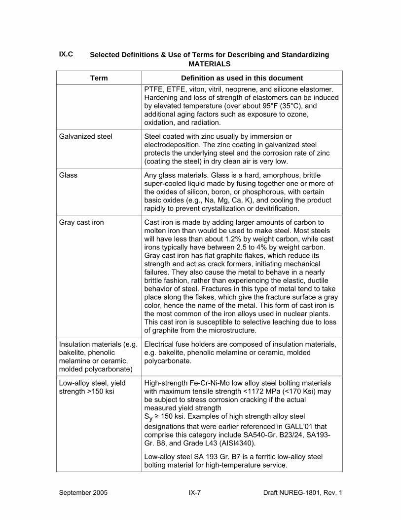
IX.C Selected Definitions & Use of Terms for Describing and Standardizing MATERIALS
Term Definition as used in this document PTFE, ETFE, viton, vitril, neoprene, and silicone elastomer. Hardening and loss of strength of elastomers can be induced by elevated temperature (over about 95°F (35°C), and additional aging factors such as exposure to ozone, oxidation, and radiation.
Galvanized steel Steel coated with zinc usually by immersion or electrodeposition. The zinc coating in galvanized steel protects the underlying steel and the corrosion rate of zinc (coating the steel) in dry clean air is very low.
Glass Any glass materials. Glass is a hard, amorphous, brittle super-cooled liquid made by fusing together one or more of the oxides of silicon, boron, or phosphorous, with certain basic oxides (e.g., Na, Mg, Ca, K), and cooling the product rapidly to prevent crystallization or devitrification.
Gray cast iron Cast iron is made by adding larger amounts of carbon to molten iron than would be used to make steel. Most steels will have less than about 1.2% by weight carbon, while cast irons typically have between 2.5 to 4% by weight carbon. Gray cast iron has flat graphite flakes, which reduce its strength and act as crack formers, initiating mechanical failures. They also cause the metal to behave in a nearly brittle fashion, rather than experiencing the elastic, ductile behavior of steel. Fractures in this type of metal tend to take place along the flakes, which give the fracture surface a gray color, hence the name of the metal. This form of cast iron is the most common of the iron alloys used in nuclear plants. This cast iron is susceptible to selective leaching due to loss of graphite from the microstructure.
Insulation materials (e.g. bakelite, phenolic melamine or ceramic, molded polycarbonate)
Electrical fuse holders are composed of insulation materials, e.g. bakelite, phenolic melamine or ceramic, molded polycarbonate.
Low-alloy steel, yield strength >150 ksi
High-strength Fe-Cr-Ni-Mo low alloy steel bolting materials with maximum tensile strength <1172 MPa (<170 Ksi) may be subject to stress corrosion cracking if the actual measured yield strength Sy ≥ 150 ksi. Examples of high strength alloy steel designations that were earlier referenced in GALL’01 that comprise this category include SA540-Gr. B23/24, SA193Gr. B8, and Grade L43 (AISI4340).
Low-alloy steel SA 193 Gr. B7 is a ferritic low-alloy steel bolting material for high-temperature service.
September 2005 IX-7 Draft NUREG-1801, Rev. 1
IX.C Selected Definitions & Use of Terms for Describing and Standardizing MATERIALS
Term Definition as used in this document
Low-alloy steel includes AISI steels 4140, 4142, 4145, 4140H, 4142H, and 4145H (UNS#: G41400, G41420, G41450, H41400, H41420, H41450). Bolting fabricated from high-strength (actual measured yield strength Sy ≥ 150 ksi) low-alloy steel SA 193 Gr. B7 is susceptible to stress corrosion cracking.
Lubrite Lubrite refers to a patented technology in which the bearing substrate (bronze is commonly used, but, in unusual environments, other materials, ranging from stainless steel and nodular-iron to tool-steel, are used) is fastened to lubricant. Lubrite is often defined as bronze attached to ASTM B22, alloy 905, with G10 lubricant.
Even though lubrite bearings are characterized as maintenance-free, because of the differences in installation, fineness of the surfaces, and lubricant characteristics, they can be subjected to mechanical wear and fretting.
Malleable iron Malleable iron usually means malleable cast iron, characterized by exhibiting some elongation and reduction in area in a tensile test. Malleable iron is one of the materials in the suite of “Porcelain, Malleable iron, aluminum, galvanized steel, cement” used to define the high voltage insulators subject to degradation of insulator quality/presence of any salt deposits or surface contamination (AMR line-item LP-07) or loss of material/mechanical wear due to wind blowing on transmission conductors (AMR line-item LP-11).
Nickel alloys Nickel-chromium-iron (molybdenum) alloys are those such as the Alloy 600 and 690. Examples of nickel alloy designations that were earlier referenced in GALL’01 that comprise this category include Alloy 182, Alloy 600, Alloy 690, Gr. 688 (X-750), Inconel 182, Inconel 82, NiCrFe, SB166, SB-167, SB-168, X-750. [2]
Polymer (e.g., rubber) Polymeric materials, such as rubber.
Porcelain Hard-quality porcelain is used as an insulator for supporting high-voltage electrical insulators. Porcelain is a hard, fine-grained ceramic that essentially consists of kaolin, quartz, and feldspar that is fired at high temperatures. Porcelain is one of the materials in the suite of “Porcelain, Malleable iron, aluminum, galvanized steel, cement” used to define the high voltage insulators subject to degradation of insulator quality/presence of any salt deposits or surface contamination (AMR line-item LP-07) or loss of material/mechanical wear due to wind blowing on
Draft NUREG-1801, Rev. 1 IX-8 September 2005
IX.C Selected Definitions & Use of Terms for Describing and Standardizing MATERIALS
Term Definition as used in this document transmission conductors (AMR line-item LP-11).
Polymers used in electrical applications
Polymers used in electrical applications include EPR, SR, EPDM, XLPE. XLPE is cross-linked polyethylene in the category of thermoplastic resins as polyethylene and polyethylene copolymers. EPR and EPDM are ethylene-propylene rubbers in the category of thermosetting elastomers.
SA508-Cl 2 forgings clad with stainless steel using a high-heat-input welding process
Quenched and tempered vacuum-treated carbon and alloy steel forgings for pressure vessels.
Stainless steel Wrought or forged austenitic, ferritic, martensitic, precipitation hardened (PH) martensitic, or duplex stainless steel (Cr content >11%) are grouped for AMRs under the term “stainless steel.” These materials are susceptible to a variety of aging effects and mechanisms, including loss of material due to pitting and crevice corrosion, and cracking due to stress corrosion cracking. In the context of license renewal, in some cases, when the recommended AMP is the same for PH stainless steel or cast austenitic stainless steel (CASS) as for stainless steel, PH stainless steel or CASS are included as a part of the stainless steel classification. However, CASS is quite susceptible to loss of fracture toughness due to thermal and neutron irradiation embrittlement. Therefore, when this aging effect is being considered, CASS is specifically designated in the AMR line-item.
Steel with stainless steel cladding may also be considered stainless steel when the aging effect is associated with the stainless steel surface of the material, rather than the composite volume of the material.
Examples of stainless steel designations that were earlier referenced in GALL’01 that comprise this category include A-286, SA193-Gr. B8, SA193-Gr. B8M, Gr. 660 (A-286), SA193-6, SA193-Gr. B8 or B-8M, SA453, Type 304, Type 304NG, Type 308, Type 308L, Type 309, Type 309L, Type 316, Type 347, Type 403, and Type 416.
Examples of CASS designations that were earlier referenced include CF-3, CF-8, CF-3M, and CF-8M. [2]
Steel For a given environment, carbon steel, alloy steel, cast iron, gray cast iron, malleable iron, and high strength low alloy steel are vulnerable to general, pitting, and crevice corrosion,
September 2005 IX-9 Draft NUREG-1801, Rev. 1
IX.C Selected Definitions & Use of Terms for Describing and Standardizing MATERIALS
Term Definition as used in this document even though the rates of aging may vary. Consequently, these metal types are generally grouped for AMRs under the broad term “steel.” Note that this does not include stainless steel. However, gray cast iron is also susceptible to selective leaching, and high strength low alloy steel is susceptible to stress corrosion cracking. Therefore, when these aging effects are being considered, these materials are specifically called out. Galvanized steel (zinc-coated carbon steel) is also included in this category of “steel” when exposed to moisture. Malleable iron is also specifically called out in the phrase “Porcelain, Malleable iron, aluminum, galvanized steel, cement” used to define the high voltage insulators in chapter VI.
Examples of steel designations that were earlier referenced in GALL’01 that comprise this category include ASTM A 36, ASTM A 285, ASTM A759, SA36, SA106-Gr. B, SA155-Gr. KCF70, SA193-Gr. B7, SA194 -Gr. 7, SA302-Gr B, SA320Gr. L43 (AISI 4340), SA333-Gr. 6, SA336, SA508-64, class 2, SA508-Cl 2 or Cl 3, SA516-Gr. 70, SA533-Gr. B, SA540Gr. B23/24, and SA582. [4]
Draft NUREG-1801, Rev. 1 IX-10 September 2005
D. Environments
The following table defines many of the standardized environments used in the preceding GALL AMR tables in Chapters II, III, IV, V, VI, VII, and VIII, of GALL’05. A complete listing of the environments, the correlation to the environmental designations in GALL’01, and their locations is found in Appendix A of the Bases Document, NUREG1833, companying the 2005 revision of the license renewal guidance documents.
Some new technical criteria, such as temperature thresholds for aging effects in common use by the industry, are added to clarify further applicability of the results.
Temperature threshold of 95°F (35°C) for thermal stresses in elastomers: In general, if the ambient temperature is less than about 95°F (35°C), then thermal aging may be considered not significant for rubber, butyl rubber, neoprene, nitrile rubber, silicone elastomer, fluoroelastomer, EPR, and EPDM [3]. Hardening and loss of strength of elastomers can be induced by thermal aging, exposure to ozone, oxidation, and radiation. When applied to the elastomers used in electrical cable insulation, it should be noted that most cable insulation is manufactured as either 75oC (167oF) or 90oC (194oF) rated material.
Temperature threshold of 140°F (60°C) for SCC in stainless steel: Stress corrosion cracking (SCC) occurs very rarely in austenitic stainless steels below 140°F (60°C). Although SCC has been observed in stagnant, oxygenated borated water systems at lower temperatures than this 140°F threshold, all of these instances have identified a significant presence of contaminants (halogens, specifically chlorides) in the failed components. With a harsh enough environment (i.e., significant contamination), SCC can occur in austenitic stainless steel at ambient temperature. However, these conditions are considered event-driven, resulting from a breakdown of chemistry controls [5, 6].
Temperature threshold of 482°F (250°C) for thermal embrittlement in CASS: CASS subjected to sustained temperatures below 250°C (482°F) will not result in a reduction of room temperature Charpy impact energy below 50 ft-lb for exposure times of approximately 300,000 hours (for CASS with ferrite content of 40% and approximately 2,500,000 hours for CASS with ferrite content of 14%) [Fig. 2; Ref. 7]. For a maximum exposure time of approximately 420,000 hours (48 EFPY), a screening temperature of 482°F is conservatively chosen because (1) the majority of nuclear grade materials is expected to contain a ferrite content well below 40%, and (2) the 50 ft-lb limit is very conservative when applied to cast austenitic materials. It is typically applied to ferritic materials, e.g., 10 CFR 50 Appendix G. For CASS components in the reactor coolant pressure boundary, this threshold is supported by the GALL’05 AMP XI.M12, "Thermal Aging Embrittlement of Cast Austenitic Stainless Steel (CASS)," with the exception of niobium-containing steels, which require evaluation on a case-by-case basis.
Specification of External or Internal Surface: Surface conditions of systems, structures, and components are monitored through visual examinations and leakage inspections to determine the existence of external and internal corrosion or deterioration. For some environments listed below such as air – indoor controlled, air – indoor uncontrolled, air – outdoor, condensation, air – indoor uncontrolled > 95° the component information description should identify whether the surface is external. This information is important, because it indicates the applicability of direct visual observation of the surface for aging
September 2005 IX-11 Draft NUREG-1801, Rev. 1
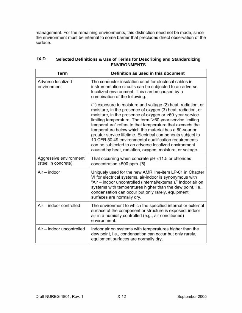
management. For the remaining environments, this distinction need not be made, since the environment must be internal to some barrier that precludes direct observation of the surface.
IX.D Selected Definitions & Use of Terms for Describing and Standardizing ENVIRONMENTS
Term Definition as used in this document
Adverse localized environment
The conductor insulation used for electrical cables in instrumentation circuits can be subjected to an adverse localized environment. This can be caused by a combination of the following.
(1) exposure to moisture and voltage (2) heat, radiation, or moisture, in the presence of oxygen (3) heat, radiation, or moisture, in the presence of oxygen or >60-year service limiting temperature. The term “>60-year service limiting temperature” refers to that temperature that exceeds the temperature below which the material has a 60-year or greater service lifetime. Electrical components subject to 10 CFR 50.49 environmental qualification requirements can be subjected to an adverse localized environment caused by heat, radiation, oxygen, moisture, or voltage.
Aggressive environment (steel in concrete)
That occurring when concrete pH <11.5 or chlorides concentration >500 ppm. [8]
Air – indoor Uniquely used for the new AMR line-item LP-01 in Chapter VI for electrical systems, air-indoor is synonymous with “Air – indoor uncontrolled (internal/external).” Indoor air on systems with temperatures higher than the dew point, i.e., condensation can occur but only rarely, equipment surfaces are normally dry.
Air – indoor controlled The environment to which the specified internal or external surface of the component or structure is exposed: indoor air in a humidity controlled (e.g., air conditioned) environment.
Air – indoor uncontrolled Indoor air on systems with temperatures higher than the dew point, i.e., condensation can occur but only rarely, equipment surfaces are normally dry.
Draft NUREG-1801, Rev. 1 IX-12 September 2005
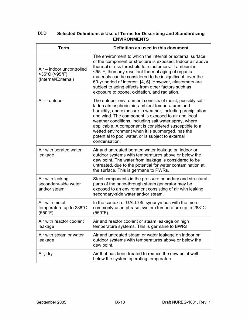
IX.D Selected Definitions & Use of Terms for Describing and Standardizing ENVIRONMENTS
Term Definition as used in this document
Air – indoor uncontrolled >35°C (>95°F) (Internal/External)
The environment to which the internal or external surface of the component or structure is exposed. Indoor air above thermal stress threshold for elastomers. If ambient is <95°F, then any resultant thermal aging of organic materials can be considered to be insignificant, over the 60-yr period of interest. [4, 5] However, elastomers are subject to aging effects from other factors such as exposure to ozone, oxidation, and radiation.
Air – outdoor The outdoor environment consists of moist, possibly salt-laden atmospheric air, ambient temperatures and humidity, and exposure to weather, including precipitation and wind. The component is exposed to air and local weather conditions, including salt water spray, where applicable. A component is considered susceptible to a wetted environment when it is submerged, has the potential to pool water, or is subject to external condensation.
Air with borated water leakage
Air and untreated borated water leakage on indoor or outdoor systems with temperatures above or below the dew point. The water from leakage is considered to be untreated, due to the potential for water contamination at the surface. This is germane to PWRs.
Air with leaking secondary-side water and/or steam
Steel components in the pressure boundary and structural parts of the once-through steam generator may be exposed to an environment consisting of air with leaking secondary-side water and/or steam.
Air with metal temperature up to 288°C (550°F)
In the context of GALL’05, synonymous with the more commonly-used phrase, system temperature up to 288°C (550°F).
Air with reactor coolant leakage
Air and reactor coolant or steam leakage on high temperature systems. This is germane to BWRs.
Air with steam or water leakage
Air and untreated steam or water leakage on indoor or outdoor systems with temperatures above or below the dew point.
Air, dry Air that has been treated to reduce the dew point well below the system operating temperature
September 2005 IX-13 Draft NUREG-1801, Rev. 1
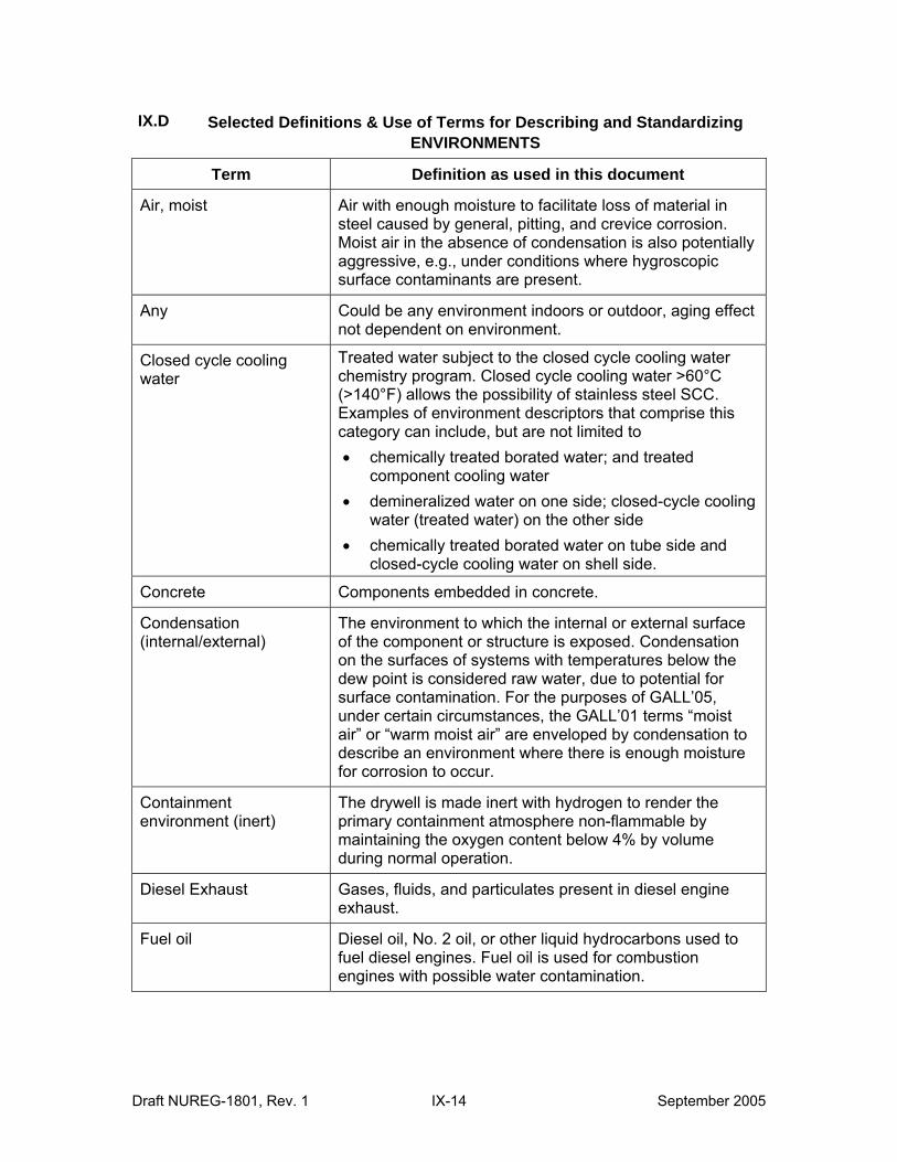
IX.D Selected Definitions & Use of Terms for Describing and Standardizing ENVIRONMENTS
Term Definition as used in this document
Air, moist Air with enough moisture to facilitate loss of material in steel caused by general, pitting, and crevice corrosion. Moist air in the absence of condensation is also potentially aggressive, e.g., under conditions where hygroscopic surface contaminants are present.
Any Could be any environment indoors or outdoor, aging effect not dependent on environment.
Closed cycle cooling water
Treated water subject to the closed cycle cooling water chemistry program. Closed cycle cooling water >60°C (>140°F) allows the possibility of stainless steel SCC. Examples of environment descriptors that comprise this category can include, but are not limited to • chemically treated borated water; and treated
component cooling water • demineralized water on one side; closed-cycle cooling
water (treated water) on the other side • chemically treated borated water on tube side and
closed-cycle cooling water on shell side.
Concrete Components embedded in concrete.
Condensation (internal/external)
The environment to which the internal or external surface of the component or structure is exposed. Condensation on the surfaces of systems with temperatures below the dew point is considered raw water, due to potential for surface contamination. For the purposes of GALL’05, under certain circumstances, the GALL’01 terms “moist air” or “warm moist air” are enveloped by condensation to describe an environment where there is enough moisture for corrosion to occur.
Containment environment (inert)
The drywell is made inert with hydrogen to render the primary containment atmosphere non-flammable by maintaining the oxygen content below 4% by volume during normal operation.
Diesel Exhaust Gases, fluids, and particulates present in diesel engine exhaust.
Fuel oil Diesel oil, No. 2 oil, or other liquid hydrocarbons used to fuel diesel engines. Fuel oil is used for combustion engines with possible water contamination.
Draft NUREG-1801, Rev. 1 IX-14 September 2005
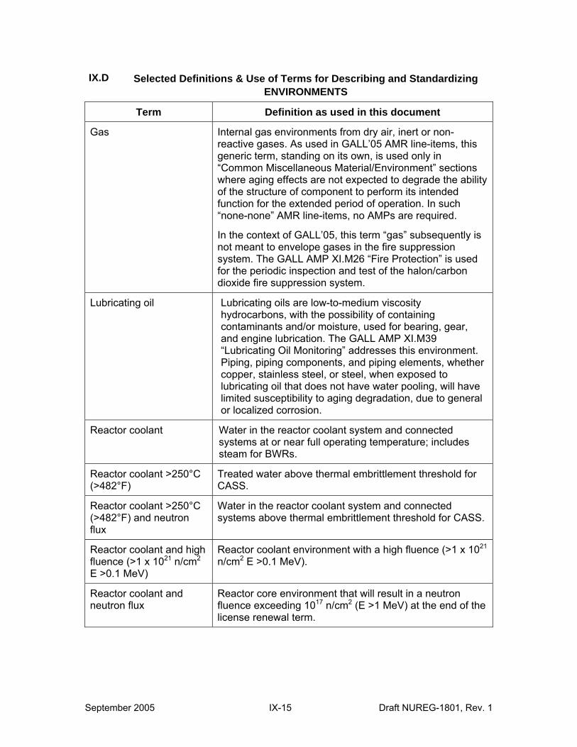
IX.D Selected Definitions & Use of Terms for Describing and Standardizing ENVIRONMENTS
Term Definition as used in this document
Gas Internal gas environments from dry air, inert or nonreactive gases. As used in GALL’05 AMR line-items, this generic term, standing on its own, is used only in “Common Miscellaneous Material/Environment” sections where aging effects are not expected to degrade the ability of the structure of component to perform its intended function for the extended period of operation. In such “none-none” AMR line-items, no AMPs are required.
In the context of GALL’05, this term “gas” subsequently is not meant to envelope gases in the fire suppression system. The GALL AMP XI.M26 “Fire Protection” is used for the periodic inspection and test of the halon/carbon dioxide fire suppression system.
Lubricating oil Lubricating oils are low-to-medium viscosity hydrocarbons, with the possibility of containing contaminants and/or moisture, used for bearing, gear, and engine lubrication. The GALL AMP XI.M39 “Lubricating Oil Monitoring” addresses this environment. Piping, piping components, and piping elements, whether copper, stainless steel, or steel, when exposed to lubricating oil that does not have water pooling, will have limited susceptibility to aging degradation, due to general or localized corrosion.
Reactor coolant Water in the reactor coolant system and connected systems at or near full operating temperature; includes steam for BWRs.
Reactor coolant >250°C (>482°F)
Treated water above thermal embrittlement threshold for CASS.
Reactor coolant >250°C (>482°F) and neutron flux
Water in the reactor coolant system and connected systems above thermal embrittlement threshold for CASS.
Reactor coolant and high fluence (>1 x 10²¹ n/cm2
E >0.1 MeV)
Reactor coolant environment with a high fluence (>1 x 10²¹
n/cm2 E >0.1 MeV).
Reactor coolant and neutron flux
Reactor core environment that will result in a neutron fluence exceeding 1017 n/cm2 (E >1 MeV) at the end of the license renewal term.
September 2005 IX-15 Draft NUREG-1801, Rev. 1
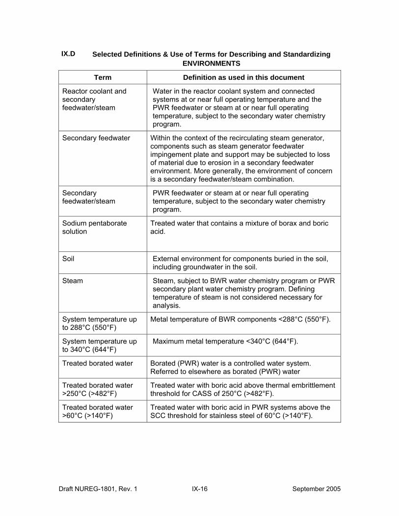
IX.D Selected Definitions & Use of Terms for Describing and Standardizing ENVIRONMENTS
Term Definition as used in this document
Reactor coolant and secondary feedwater/steam
Water in the reactor coolant system and connected systems at or near full operating temperature and the PWR feedwater or steam at or near full operating temperature, subject to the secondary water chemistry program.
Secondary feedwater Within the context of the recirculating steam generator, components such as steam generator feedwater impingement plate and support may be subjected to loss of material due to erosion in a secondary feedwater environment. More generally, the environment of concern is a secondary feedwater/steam combination.
Secondary feedwater/steam
PWR feedwater or steam at or near full operating temperature, subject to the secondary water chemistry program.
Sodium pentaborate solution
Treated water that contains a mixture of borax and boric acid.
Soil External environment for components buried in the soil, including groundwater in the soil.
Steam Steam, subject to BWR water chemistry program or PWR secondary plant water chemistry program. Defining temperature of steam is not considered necessary for analysis.
System temperature up to 288°C (550°F)
Metal temperature of BWR components <288°C (550°F).
System temperature up to 340°C (644°F)
Maximum metal temperature <340°C (644°F).
Treated borated water Borated (PWR) water is a controlled water system. Referred to elsewhere as borated (PWR) water
Treated borated water >250°C (>482°F)
Treated water with boric acid above thermal embrittlement threshold for CASS of 250°C (>482°F).
Treated borated water >60°C (>140°F)
Treated water with boric acid in PWR systems above the SCC threshold for stainless steel of 60°C (>140°F).
Draft NUREG-1801, Rev. 1 IX-16 September 2005
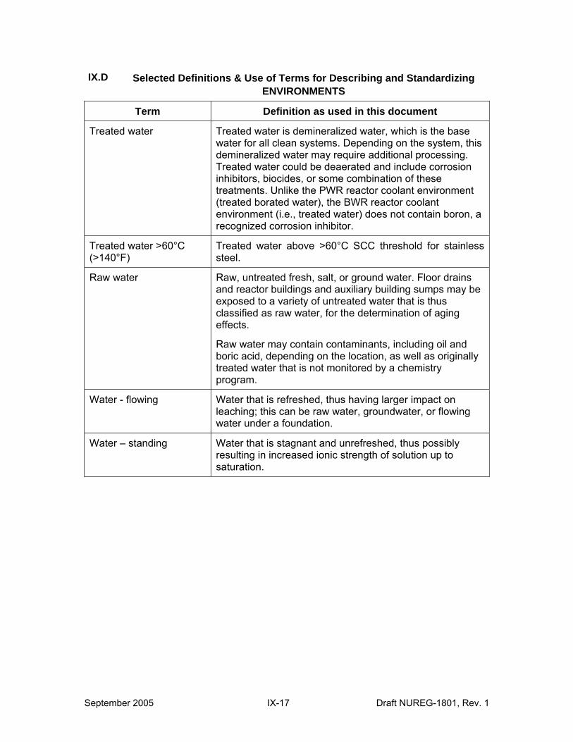
IX.D Selected Definitions & Use of Terms for Describing and Standardizing ENVIRONMENTS
Term Definition as used in this document
Treated water Treated water is demineralized water, which is the base water for all clean systems. Depending on the system, this demineralized water may require additional processing. Treated water could be deaerated and include corrosion inhibitors, biocides, or some combination of these treatments. Unlike the PWR reactor coolant environment (treated borated water), the BWR reactor coolant environment (i.e., treated water) does not contain boron, a recognized corrosion inhibitor.
Treated water >60°C (>140°F)
Treated water above >60°C SCC threshold for stainless steel.
Raw water Raw, untreated fresh, salt, or ground water. Floor drains and reactor buildings and auxiliary building sumps may be exposed to a variety of untreated water that is thus classified as raw water, for the determination of aging effects.
Raw water may contain contaminants, including oil and boric acid, depending on the location, as well as originally treated water that is not monitored by a chemistry program.
Water - flowing Water that is refreshed, thus having larger impact on leaching; this can be raw water, groundwater, or flowing water under a foundation.
Water – standing Water that is stagnant and unrefreshed, thus possibly resulting in increased ionic strength of solution up to saturation.
September 2005 IX-17 Draft NUREG-1801, Rev. 1
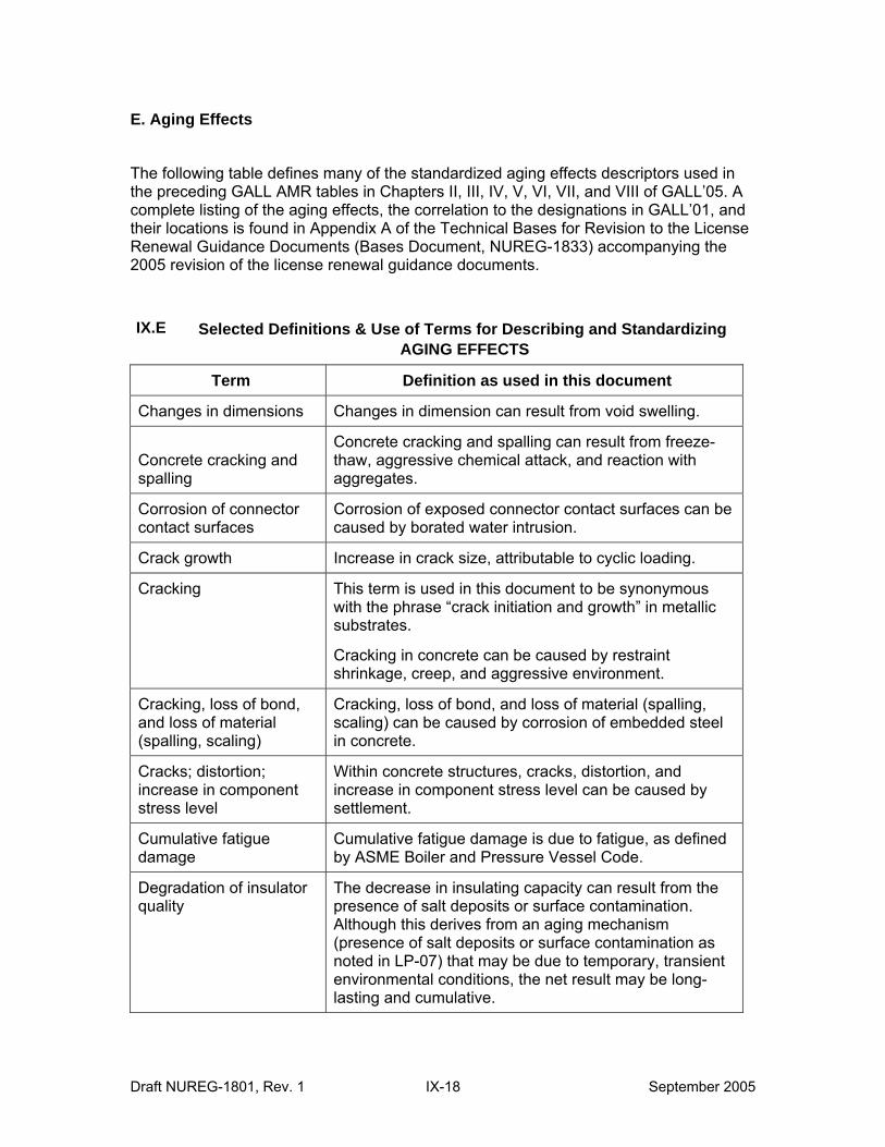
E. Aging Effects
The following table defines many of the standardized aging effects descriptors used in the preceding GALL AMR tables in Chapters II, III, IV, V, VI, VII, and VIII of GALL’05. A complete listing of the aging effects, the correlation to the designations in GALL’01, and their locations is found in Appendix A of the Technical Bases for Revision to the License Renewal Guidance Documents (Bases Document, NUREG-1833) accompanying the 2005 revision of the license renewal guidance documents.
IX.E Selected Definitions & Use of Terms for Describing and Standardizing AGING EFFECTS
Term Definition as used in this document
Changes in dimensions Changes in dimension can result from void swelling.
Concrete cracking and spalling
Concrete cracking and spalling can result from freeze-thaw, aggressive chemical attack, and reaction with aggregates.
Corrosion of connector contact surfaces
Corrosion of exposed connector contact surfaces can be caused by borated water intrusion.
Crack growth Increase in crack size, attributable to cyclic loading.
Cracking This term is used in this document to be synonymous with the phrase “crack initiation and growth” in metallic substrates.
Cracking in concrete can be caused by restraint shrinkage, creep, and aggressive environment.
Cracking, loss of bond, and loss of material (spalling, scaling)
Cracking, loss of bond, and loss of material (spalling, scaling) can be caused by corrosion of embedded steel in concrete.
Cracks; distortion; increase in component stress level
Within concrete structures, cracks, distortion, and increase in component stress level can be caused by settlement.
Cumulative fatigue damage
Cumulative fatigue damage is due to fatigue, as defined by ASME Boiler and Pressure Vessel Code.
Degradation of insulator quality
The decrease in insulating capacity can result from the presence of salt deposits or surface contamination. Although this derives from an aging mechanism (presence of salt deposits or surface contamination as noted in LP-07) that may be due to temporary, transient environmental conditions, the net result may be long-lasting and cumulative.
Draft NUREG-1801, Rev. 1 IX-18 September 2005
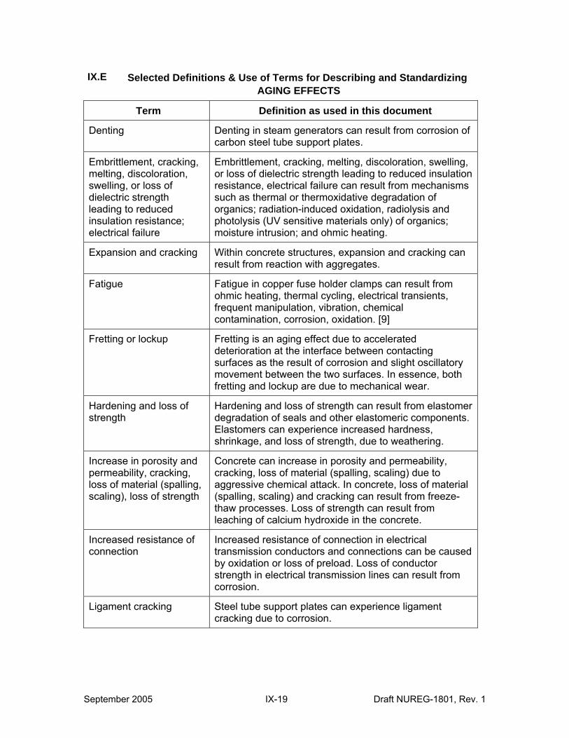
IX.E Selected Definitions & Use of Terms for Describing and Standardizing AGING EFFECTS
Term Definition as used in this document
Denting Denting in steam generators can result from corrosion of carbon steel tube support plates.
Embrittlement, cracking, melting, discoloration, swelling, or loss of dielectric strength leading to reduced insulation resistance; electrical failure
Embrittlement, cracking, melting, discoloration, swelling, or loss of dielectric strength leading to reduced insulation resistance, electrical failure can result from mechanisms such as thermal or thermoxidative degradation of organics; radiation-induced oxidation, radiolysis and photolysis (UV sensitive materials only) of organics; moisture intrusion; and ohmic heating.
Expansion and cracking Within concrete structures, expansion and cracking can result from reaction with aggregates.
Fatigue Fatigue in copper fuse holder clamps can result from ohmic heating, thermal cycling, electrical transients, frequent manipulation, vibration, chemical contamination, corrosion, oxidation. [9]
Fretting or lockup Fretting is an aging effect due to accelerated deterioration at the interface between contacting surfaces as the result of corrosion and slight oscillatory movement between the two surfaces. In essence, both fretting and lockup are due to mechanical wear.
Hardening and loss of strength
Hardening and loss of strength can result from elastomer degradation of seals and other elastomeric components. Elastomers can experience increased hardness, shrinkage, and loss of strength, due to weathering.
Increase in porosity and permeability, cracking, loss of material (spalling, scaling), loss of strength
Concrete can increase in porosity and permeability, cracking, loss of material (spalling, scaling) due to aggressive chemical attack. In concrete, loss of material (spalling, scaling) and cracking can result from freeze-thaw processes. Loss of strength can result from leaching of calcium hydroxide in the concrete.
Increased resistance of connection
Increased resistance of connection in electrical transmission conductors and connections can be caused by oxidation or loss of preload. Loss of conductor strength in electrical transmission lines can result from corrosion.
Ligament cracking Steel tube support plates can experience ligament cracking due to corrosion.
September 2005 IX-19 Draft NUREG-1801, Rev. 1

IX.E Selected Definitions & Use of Terms for Describing and Standardizing AGING EFFECTS
Term Definition as used in this document
Localized damage and breakdown of insulation leading to electrical failure
Localized damage in polymeric electrical conductor insulation leading to electrical failure is due to moisture intrusion, and the formation of water trees.
Loosening of bolted connections
The loosening of bolted bus duct connections due to thermal cycling can result from ohmic heating. [10, 11]
Loss of fracture toughness
Loss of fracture toughness can result from various aging mechanisms including thermal aging, thermal aging embrittlement, and neutron irradiation embrittlement.
Loss of leak tightness Steel airlocks can experience loss of leak tightness in closed position resulting from mechanical wear of locks, hinges, and closure mechanisms.
Loss of material Loss of material may be due to general corrosion, boric acid corrosion, pitting corrosion, galvanic corrosion, crevice corrosion, erosion, fretting, flow-accelerated corrosion, MIC, fouling, selective leaching, wastage, wear, and aggressive chemical attack. In concrete structures, loss of material can also be caused by abrasion or cavitation or corrosion of embedded steel.
For high voltage insulators, loss of material can be attributed to mechanical wear or wind-induced abrasion and fatigue due to wind blowing on transmission conductors. [10]
Loss of material, loss of form
In earthen water-control structures, the loss of material and loss of form can result from erosion, settlement, sedimentation, frost action, waves, currents, surface runoff, and seepage.
Loss of mechanical function
Loss of mechanical function in Class 1 piping and components (such as constant and variable load spring hangers, guides, stops, sliding surfaces, design clearances, and vibration isolators) fabricated from steel or other materials, such as lubrite, can experience loss of mechanical function due to corrosion, distortion, dirt, overload, fatigue due to vibratory and cyclic thermal loads, or elastomer hardening.
Draft NUREG-1801, Rev. 1 IX-20 September 2005
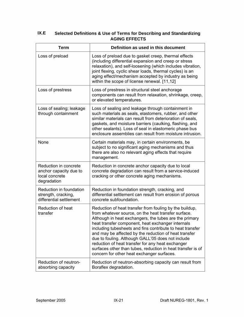
IX.E Selected Definitions & Use of Terms for Describing and Standardizing AGING EFFECTS
Term Definition as used in this document
Loss of preload Loss of preload due to gasket creep, thermal effects (including differential expansion and creep or stress relaxation), and self-loosening (which includes vibration, joint flexing, cyclic shear loads, thermal cycles) is an aging effect/mechanism accepted by industry as being within the scope of license renewal. [11,12]
Loss of prestress Loss of prestress in structural steel anchorage components can result from relaxation, shrinkage, creep, or elevated temperatures.
Loss of sealing; leakage through containment
Loss of sealing and leakage through containment in such materials as seals, elastomers, rubber, and other similar materials can result from deterioration of seals, gaskets, and moisture barriers (caulking, flashing, and other sealants). Loss of seal in elastomeric phase bus enclosure assemblies can result from moisture intrusion.
None Certain materials may, in certain environments, be subject to no significant aging mechanisms and thus there are also no relevant aging effects that require management.
Reduction in concrete anchor capacity due to local concrete degradation
Reduction in concrete anchor capacity due to local concrete degradation can result from a service-induced cracking or other concrete aging mechanisms.
Reduction in foundation strength, cracking, differential settlement
Reduction in foundation strength, cracking, and differential settlement can result from erosion of porous concrete subfoundation.
Reduction of heat transfer
Reduction of heat transfer from fouling by the buildup, from whatever source, on the heat transfer surface. Although in heat exchangers, the tubes are the primary heat transfer component, heat exchanger internals including tubesheets and fins contribute to heat transfer and may be affected by the reduction of heat transfer due to fouling. Although GALL’05 does not include reduction of heat transfer for any heat exchanger surfaces other than tubes, reduction in heat transfer is of concern for other heat exchanger surfaces.
Reduction of neutron-absorbing capacity
Reduction of neutron-absorbing capacity can result from Boraflex degradation.
September 2005 IX-21 Draft NUREG-1801, Rev. 1
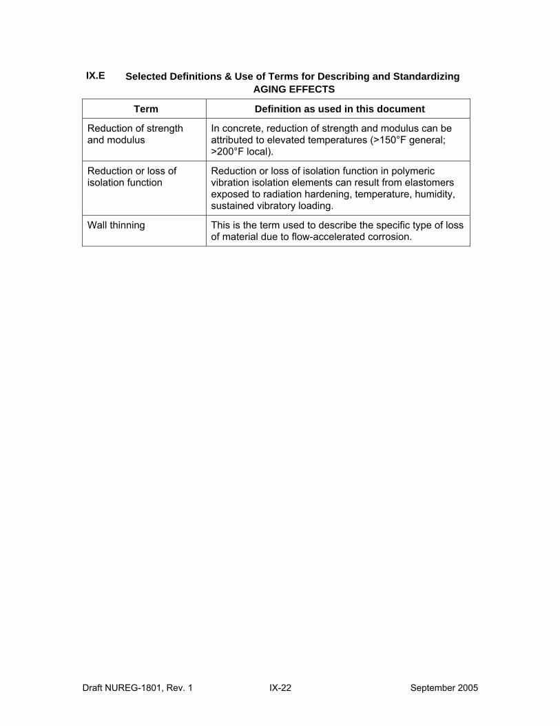
IX.E Selected Definitions & Use of Terms for Describing and Standardizing AGING EFFECTS
Term Definition as used in this document
Reduction of strength and modulus
In concrete, reduction of strength and modulus can be attributed to elevated temperatures (>150°F general; >200°F local).
Reduction or loss of isolation function
Reduction or loss of isolation function in polymeric vibration isolation elements can result from elastomers exposed to radiation hardening, temperature, humidity, sustained vibratory loading.
Wall thinning This is the term used to describe the specific type of loss of material due to flow-accelerated corrosion.
Draft NUREG-1801, Rev. 1 IX-22 September 2005
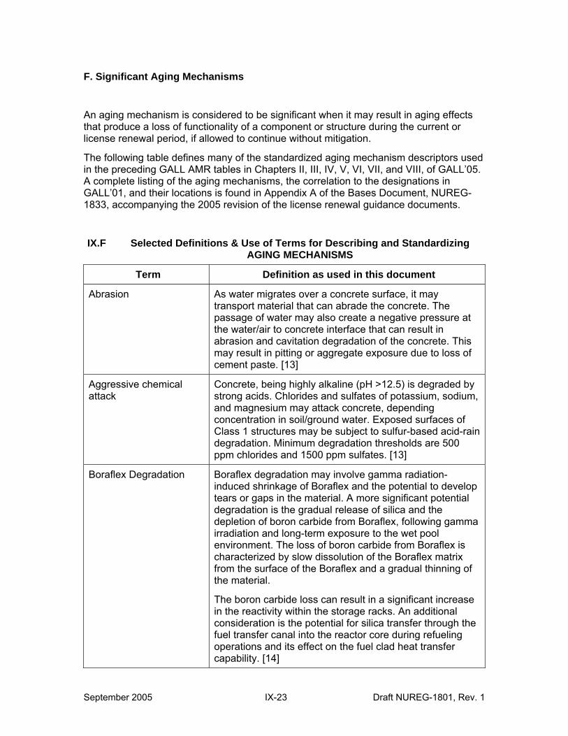
F. Significant Aging Mechanisms
An aging mechanism is considered to be significant when it may result in aging effects that produce a loss of functionality of a component or structure during the current or license renewal period, if allowed to continue without mitigation.
The following table defines many of the standardized aging mechanism descriptors used in the preceding GALL AMR tables in Chapters II, III, IV, V, VI, VII, and VIII, of GALL’05. A complete listing of the aging mechanisms, the correlation to the designations in GALL’01, and their locations is found in Appendix A of the Bases Document, NUREG1833, accompanying the 2005 revision of the license renewal guidance documents.
IX.F Selected Definitions & Use of Terms for Describing and Standardizing AGING MECHANISMS
Term Definition as used in this document
Abrasion As water migrates over a concrete surface, it may transport material that can abrade the concrete. The passage of water may also create a negative pressure at the water/air to concrete interface that can result in abrasion and cavitation degradation of the concrete. This may result in pitting or aggregate exposure due to loss of cement paste. [13]
Aggressive chemical attack
Concrete, being highly alkaline (pH >12.5) is degraded by strong acids. Chlorides and sulfates of potassium, sodium, and magnesium may attack concrete, depending concentration in soil/ground water. Exposed surfaces of Class 1 structures may be subject to sulfur-based acid-rain degradation. Minimum degradation thresholds are 500 ppm chlorides and 1500 ppm sulfates. [13]
Boraflex Degradation Boraflex degradation may involve gamma radiation-induced shrinkage of Boraflex and the potential to develop tears or gaps in the material. A more significant potential degradation is the gradual release of silica and the depletion of boron carbide from Boraflex, following gamma irradiation and long-term exposure to the wet pool environment. The loss of boron carbide from Boraflex is characterized by slow dissolution of the Boraflex matrix from the surface of the Boraflex and a gradual thinning of the material.
The boron carbide loss can result in a significant increase in the reactivity within the storage racks. An additional consideration is the potential for silica transfer through the fuel transfer canal into the reactor core during refueling operations and its effect on the fuel clad heat transfer capability. [14]
September 2005 IX-23 Draft NUREG-1801, Rev. 1
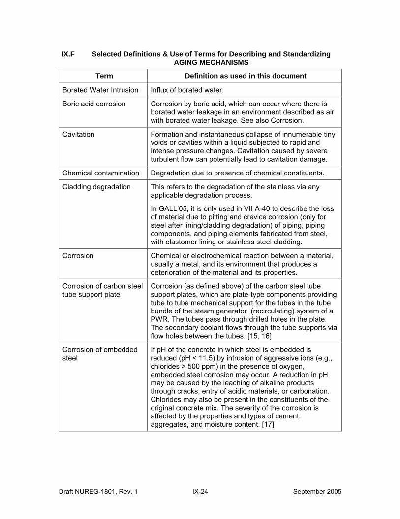
IX.F Selected Definitions & Use of Terms for Describing and Standardizing AGING MECHANISMS
Term Definition as used in this document
Borated Water Intrusion Influx of borated water.
Boric acid corrosion Corrosion by boric acid, which can occur where there is borated water leakage in an environment described as air with borated water leakage. See also Corrosion.
Cavitation Formation and instantaneous collapse of innumerable tiny voids or cavities within a liquid subjected to rapid and intense pressure changes. Cavitation caused by severe turbulent flow can potentially lead to cavitation damage.
Chemical contamination Degradation due to presence of chemical constituents.
Cladding degradation This refers to the degradation of the stainless via any applicable degradation process.
In GALL’05, it is only used in VII A-40 to describe the loss of material due to pitting and crevice corrosion (only for steel after lining/cladding degradation) of piping, piping components, and piping elements fabricated from steel, with elastomer lining or stainless steel cladding.
Corrosion Chemical or electrochemical reaction between a material, usually a metal, and its environment that produces a deterioration of the material and its properties.
Corrosion of carbon steel tube support plate
Corrosion (as defined above) of the carbon steel tube support plates, which are plate-type components providing tube to tube mechanical support for the tubes in the tube bundle of the steam generator (recirculating) system of a PWR. The tubes pass through drilled holes in the plate. The secondary coolant flows through the tube supports via flow holes between the tubes. [15, 16]
Corrosion of embedded steel
If pH of the concrete in which steel is embedded is reduced (pH < 11.5) by intrusion of aggressive ions (e.g., chlorides > 500 ppm) in the presence of oxygen, embedded steel corrosion may occur. A reduction in pH may be caused by the leaching of alkaline products through cracks, entry of acidic materials, or carbonation. Chlorides may also be present in the constituents of the original concrete mix. The severity of the corrosion is affected by the properties and types of cement, aggregates, and moisture content. [17]
Draft NUREG-1801, Rev. 1 IX-24 September 2005
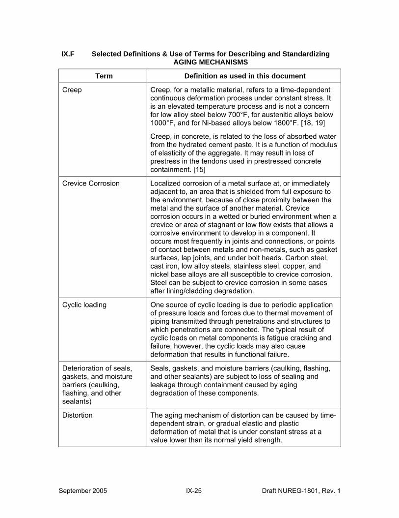
IX.F Selected Definitions & Use of Terms for Describing and Standardizing AGING MECHANISMS
Term Definition as used in this document
Creep Creep, for a metallic material, refers to a time-dependent continuous deformation process under constant stress. It is an elevated temperature process and is not a concern for low alloy steel below 700°F, for austenitic alloys below 1000°F, and for Ni-based alloys below 1800°F. [18, 19]
Creep, in concrete, is related to the loss of absorbed water from the hydrated cement paste. It is a function of modulus of elasticity of the aggregate. It may result in loss of prestress in the tendons used in prestressed concrete containment. [15]
Crevice Corrosion Localized corrosion of a metal surface at, or immediately adjacent to, an area that is shielded from full exposure to the environment, because of close proximity between the metal and the surface of another material. Crevice corrosion occurs in a wetted or buried environment when a crevice or area of stagnant or low flow exists that allows a corrosive environment to develop in a component. It occurs most frequently in joints and connections, or points of contact between metals and non-metals, such as gasket surfaces, lap joints, and under bolt heads. Carbon steel, cast iron, low alloy steels, stainless steel, copper, and nickel base alloys are all susceptible to crevice corrosion. Steel can be subject to crevice corrosion in some cases after lining/cladding degradation.
Cyclic loading One source of cyclic loading is due to periodic application of pressure loads and forces due to thermal movement of piping transmitted through penetrations and structures to which penetrations are connected. The typical result of cyclic loads on metal components is fatigue cracking and failure; however, the cyclic loads may also cause deformation that results in functional failure.
Deterioration of seals, gaskets, and moisture barriers (caulking, flashing, and other sealants)
Seals, gaskets, and moisture barriers (caulking, flashing, and other sealants) are subject to loss of sealing and leakage through containment caused by aging degradation of these components.
Distortion The aging mechanism of distortion can be caused by time-dependent strain, or gradual elastic and plastic deformation of metal that is under constant stress at a value lower than its normal yield strength.
September 2005 IX-25 Draft NUREG-1801, Rev. 1
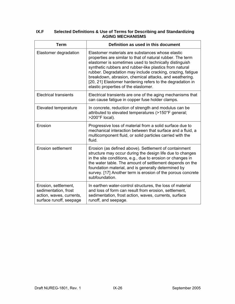
IX.F Selected Definitions & Use of Terms for Describing and Standardizing AGING MECHANISMS
Term Definition as used in this document
Elastomer degradation Elastomer materials are substances whose elastic properties are similar to that of natural rubber. The term elastomer is sometimes used to technically distinguish synthetic rubbers and rubber-like plastics from natural rubber. Degradation may include cracking, crazing, fatigue breakdown, abrasion, chemical attacks, and weathering. [20, 21] Elastomer hardening refers to the degradation in elastic properties of the elastomer.
Electrical transients Electrical transients are one of the aging mechanisms that can cause fatigue in copper fuse holder clamps.
Elevated temperature In concrete, reduction of strength and modulus can be attributed to elevated temperatures (>150°F general; >200°F local).
Erosion Progressive loss of material from a solid surface due to mechanical interaction between that surface and a fluid, a multicomponent fluid, or solid particles carried with the fluid.
Erosion settlement Erosion (as defined above). Settlement of containment structure may occur during the design life due to changes in the site conditions, e.g., due to erosion or changes in the water table. The amount of settlement depends on the foundation material, and is generally determined by survey. [17] Another term is erosion of the porous concrete subfoundation.
Erosion, settlement, sedimentation, frost action, waves, currents, surface runoff, seepage
In earthen water-control structures, the loss of material and loss of form can result from erosion, settlement, sedimentation, frost action, waves, currents, surface runoff, and seepage.
Draft NUREG-1801, Rev. 1 IX-26 September 2005
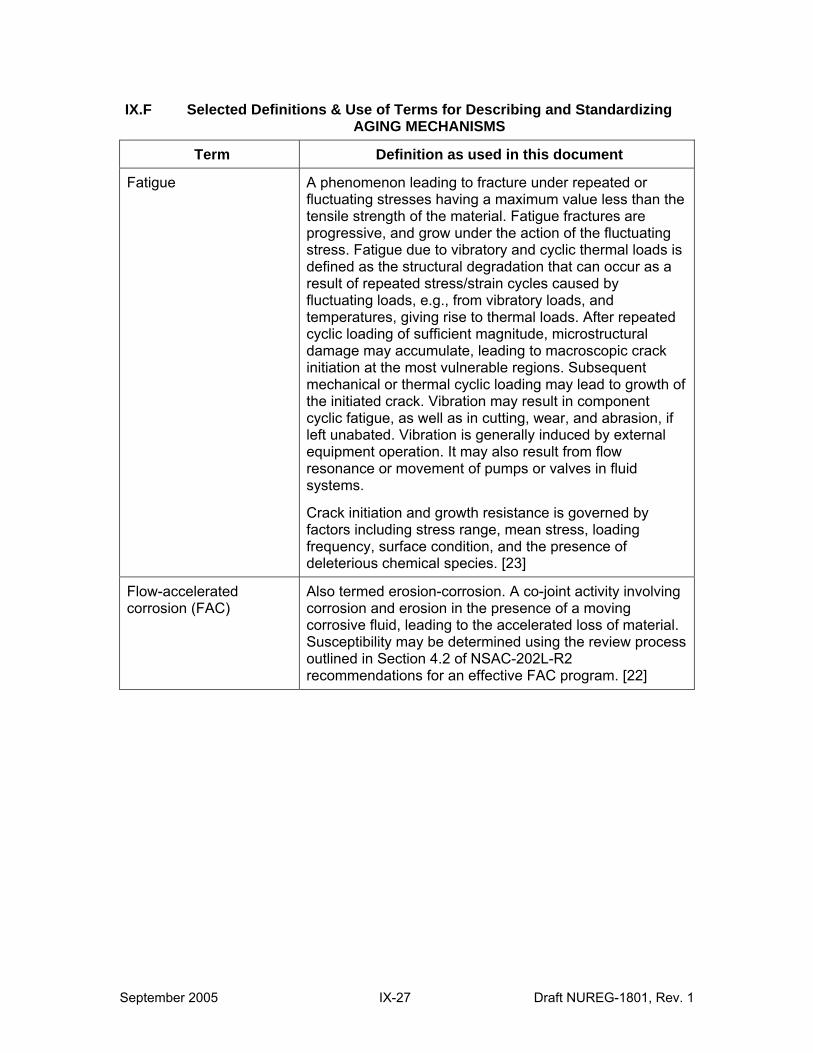
IX.F Selected Definitions & Use of Terms for Describing and Standardizing AGING MECHANISMS
Term Definition as used in this document
Fatigue A phenomenon leading to fracture under repeated or fluctuating stresses having a maximum value less than the tensile strength of the material. Fatigue fractures are progressive, and grow under the action of the fluctuating stress. Fatigue due to vibratory and cyclic thermal loads is defined as the structural degradation that can occur as a result of repeated stress/strain cycles caused by fluctuating loads, e.g., from vibratory loads, and temperatures, giving rise to thermal loads. After repeated cyclic loading of sufficient magnitude, microstructural damage may accumulate, leading to macroscopic crack initiation at the most vulnerable regions. Subsequent mechanical or thermal cyclic loading may lead to growth of the initiated crack. Vibration may result in component cyclic fatigue, as well as in cutting, wear, and abrasion, if left unabated. Vibration is generally induced by external equipment operation. It may also result from flow resonance or movement of pumps or valves in fluid systems.
Crack initiation and growth resistance is governed by factors including stress range, mean stress, loading frequency, surface condition, and the presence of deleterious chemical species. [23]
Flow-accelerated corrosion (FAC)
Also termed erosion-corrosion. A co-joint activity involving corrosion and erosion in the presence of a moving corrosive fluid, leading to the accelerated loss of material. Susceptibility may be determined using the review process outlined in Section 4.2 of NSAC-202L-R2 recommendations for an effective FAC program. [22]
September 2005 IX-27 Draft NUREG-1801, Rev. 1
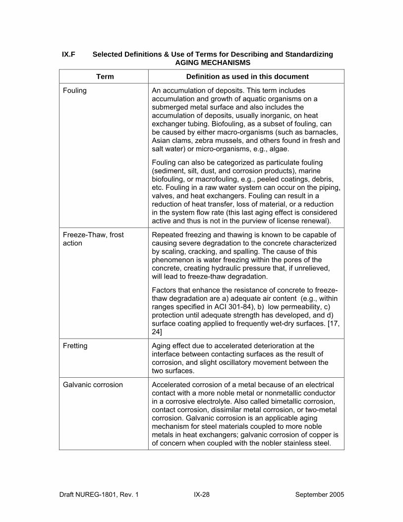
IX.F Selected Definitions & Use of Terms for Describing and Standardizing AGING MECHANISMS
Term Definition as used in this document
Fouling An accumulation of deposits. This term includes accumulation and growth of aquatic organisms on a submerged metal surface and also includes the accumulation of deposits, usually inorganic, on heat exchanger tubing. Biofouling, as a subset of fouling, can be caused by either macro-organisms (such as barnacles, Asian clams, zebra mussels, and others found in fresh and salt water) or micro-organisms, e.g., algae.
Fouling can also be categorized as particulate fouling (sediment, silt, dust, and corrosion products), marine biofouling, or macrofouling, e.g., peeled coatings, debris, etc. Fouling in a raw water system can occur on the piping, valves, and heat exchangers. Fouling can result in a reduction of heat transfer, loss of material, or a reduction in the system flow rate (this last aging effect is considered active and thus is not in the purview of license renewal).
Freeze-Thaw, frost action
Repeated freezing and thawing is known to be capable of causing severe degradation to the concrete characterized by scaling, cracking, and spalling. The cause of this phenomenon is water freezing within the pores of the concrete, creating hydraulic pressure that, if unrelieved, will lead to freeze-thaw degradation.
Factors that enhance the resistance of concrete to freeze-thaw degradation are a) adequate air content (e.g., within ranges specified in ACI 301-84), b) low permeability, c) protection until adequate strength has developed, and d) surface coating applied to frequently wet-dry surfaces. [17, 24]
Fretting Aging effect due to accelerated deterioration at the interface between contacting surfaces as the result of corrosion, and slight oscillatory movement between the two surfaces.
Galvanic corrosion Accelerated corrosion of a metal because of an electrical contact with a more noble metal or nonmetallic conductor in a corrosive electrolyte. Also called bimetallic corrosion, contact corrosion, dissimilar metal corrosion, or two-metal corrosion. Galvanic corrosion is an applicable aging mechanism for steel materials coupled to more noble metals in heat exchangers; galvanic corrosion of copper is of concern when coupled with the nobler stainless steel.
Draft NUREG-1801, Rev. 1 IX-28 September 2005
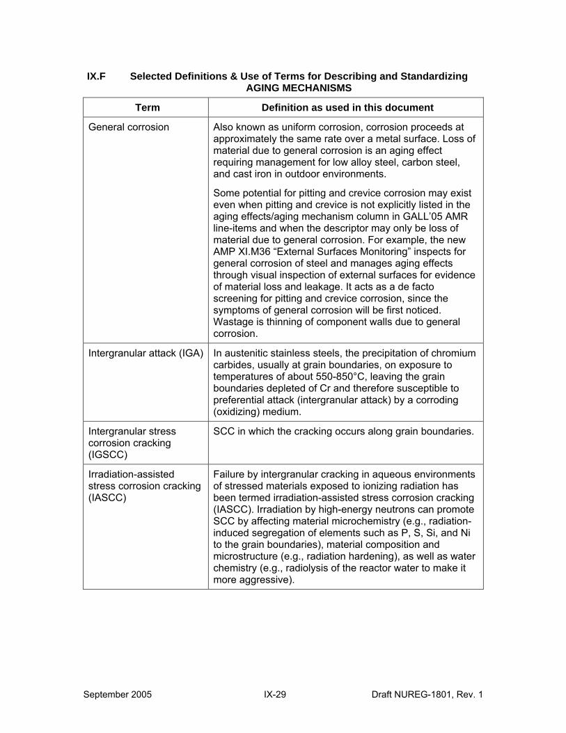
IX.F Selected Definitions & Use of Terms for Describing and Standardizing AGING MECHANISMS
Term Definition as used in this document
General corrosion Also known as uniform corrosion, corrosion proceeds at approximately the same rate over a metal surface. Loss of material due to general corrosion is an aging effect requiring management for low alloy steel, carbon steel, and cast iron in outdoor environments.
Some potential for pitting and crevice corrosion may exist even when pitting and crevice is not explicitly listed in the aging effects/aging mechanism column in GALL’05 AMR line-items and when the descriptor may only be loss of material due to general corrosion. For example, the new AMP XI.M36 “External Surfaces Monitoring” inspects for general corrosion of steel and manages aging effects through visual inspection of external surfaces for evidence of material loss and leakage. It acts as a de facto screening for pitting and crevice corrosion, since the symptoms of general corrosion will be first noticed. Wastage is thinning of component walls due to general corrosion.
Intergranular attack (IGA) In austenitic stainless steels, the precipitation of chromium carbides, usually at grain boundaries, on exposure to temperatures of about 550-850°C, leaving the grain boundaries depleted of Cr and therefore susceptible to preferential attack (intergranular attack) by a corroding (oxidizing) medium.
Intergranular stress corrosion cracking (IGSCC)
SCC in which the cracking occurs along grain boundaries.
Irradiation-assisted stress corrosion cracking (IASCC)
Failure by intergranular cracking in aqueous environments of stressed materials exposed to ionizing radiation has been termed irradiation-assisted stress corrosion cracking (IASCC). Irradiation by high-energy neutrons can promote SCC by affecting material microchemistry (e.g., radiation-induced segregation of elements such as P, S, Si, and Ni to the grain boundaries), material composition and microstructure (e.g., radiation hardening), as well as water chemistry (e.g., radiolysis of the reactor water to make it more aggressive).
September 2005 IX-29 Draft NUREG-1801, Rev. 1
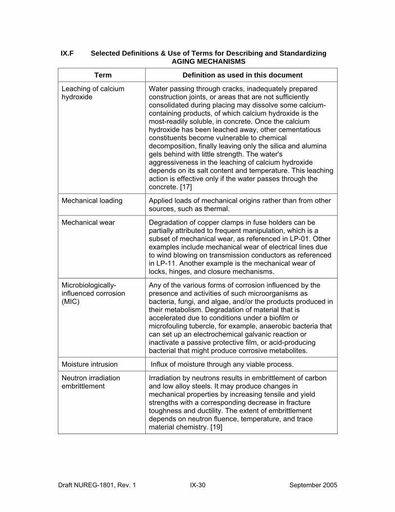
IX.F Selected Definitions & Use of Terms for Describing and Standardizing AGING MECHANISMS
Term Definition as used in this document
Leaching of calcium hydroxide
Water passing through cracks, inadequately prepared construction joints, or areas that are not sufficiently consolidated during placing may dissolve some calcium-containing products, of which calcium hydroxide is the most-readily soluble, in concrete. Once the calcium hydroxide has been leached away, other cementatious constituents become vulnerable to chemical decomposition, finally leaving only the silica and alumina gels behind with little strength. The water's aggressiveness in the leaching of calcium hydroxide depends on its salt content and temperature. This leaching action is effective only if the water passes through the concrete. [17]
Mechanical loading Applied loads of mechanical origins rather than from other sources, such as thermal.
Mechanical wear Degradation of copper clamps in fuse holders can be partially attributed to frequent manipulation, which is a subset of mechanical wear, as referenced in LP-01. Other examples include mechanical wear of electrical lines due to wind blowing on transmission conductors as referenced in LP-11. Another example is the mechanical wear of locks, hinges, and closure mechanisms.
Microbiologically-influenced corrosion (MIC)
Any of the various forms of corrosion influenced by the presence and activities of such microorganisms as bacteria, fungi, and algae, and/or the products produced in their metabolism. Degradation of material that is accelerated due to conditions under a biofilm or microfouling tubercle, for example, anaerobic bacteria that can set up an electrochemical galvanic reaction or inactivate a passive protective film, or acid-producing bacterial that might produce corrosive metabolites.
Moisture intrusion Influx of moisture through any viable process.
Neutron irradiation embrittlement
Irradiation by neutrons results in embrittlement of carbon and low alloy steels. It may produce changes in mechanical properties by increasing tensile and yield strengths with a corresponding decrease in fracture toughness and ductility. The extent of embrittlement depends on neutron fluence, temperature, and trace material chemistry. [19]
Draft NUREG-1801, Rev. 1 IX-30 September 2005
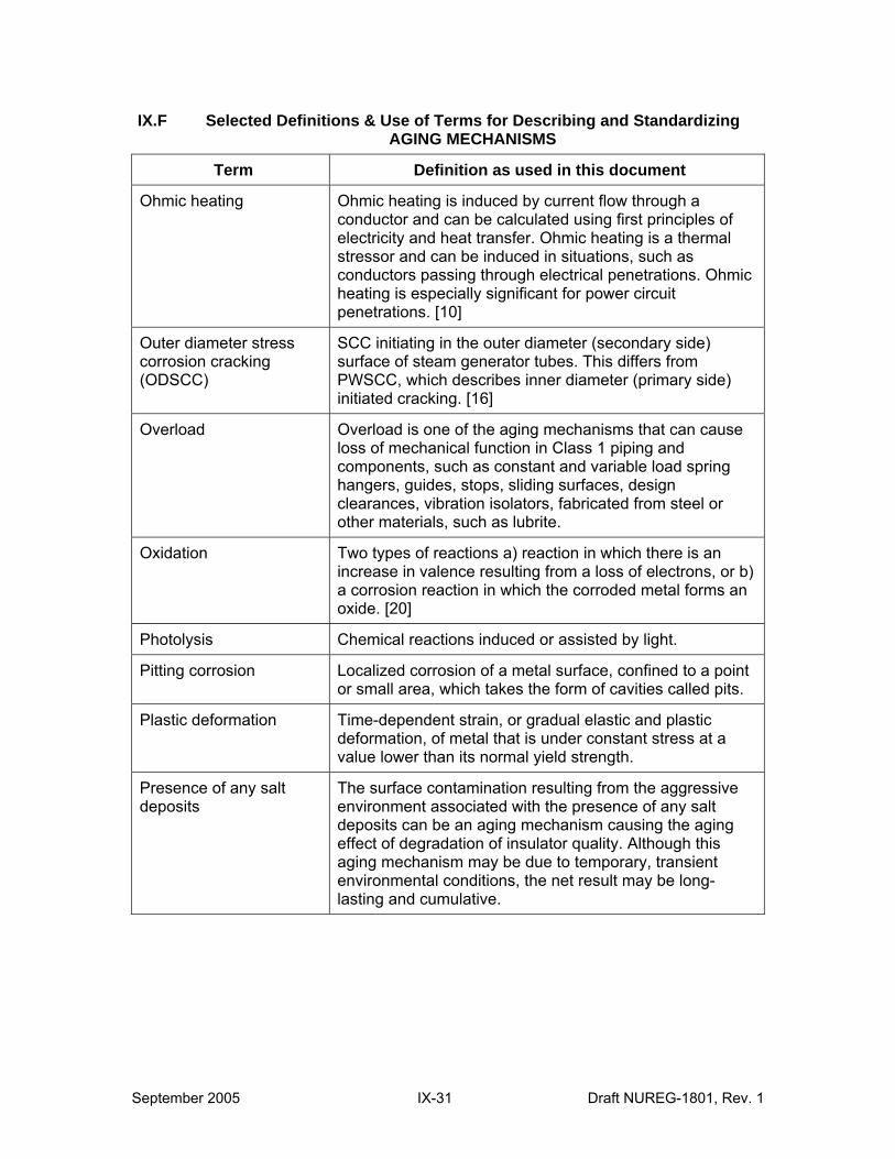
IX.F Selected Definitions & Use of Terms for Describing and Standardizing AGING MECHANISMS
Term Definition as used in this document
Ohmic heating Ohmic heating is induced by current flow through a conductor and can be calculated using first principles of electricity and heat transfer. Ohmic heating is a thermal stressor and can be induced in situations, such as conductors passing through electrical penetrations. Ohmic heating is especially significant for power circuit penetrations. [10]
Outer diameter stress corrosion cracking (ODSCC)
SCC initiating in the outer diameter (secondary side) surface of steam generator tubes. This differs from PWSCC, which describes inner diameter (primary side) initiated cracking. [16]
Overload Overload is one of the aging mechanisms that can cause loss of mechanical function in Class 1 piping and components, such as constant and variable load spring hangers, guides, stops, sliding surfaces, design clearances, vibration isolators, fabricated from steel or other materials, such as lubrite.
Oxidation Two types of reactions a) reaction in which there is an increase in valence resulting from a loss of electrons, or b) a corrosion reaction in which the corroded metal forms an oxide. [20]
Photolysis Chemical reactions induced or assisted by light.
Pitting corrosion Localized corrosion of a metal surface, confined to a point or small area, which takes the form of cavities called pits.
Plastic deformation Time-dependent strain, or gradual elastic and plastic deformation, of metal that is under constant stress at a value lower than its normal yield strength.
Presence of any salt deposits
The surface contamination resulting from the aggressive environment associated with the presence of any salt deposits can be an aging mechanism causing the aging effect of degradation of insulator quality. Although this aging mechanism may be due to temporary, transient environmental conditions, the net result may be long-lasting and cumulative.
September 2005 IX-31 Draft NUREG-1801, Rev. 1
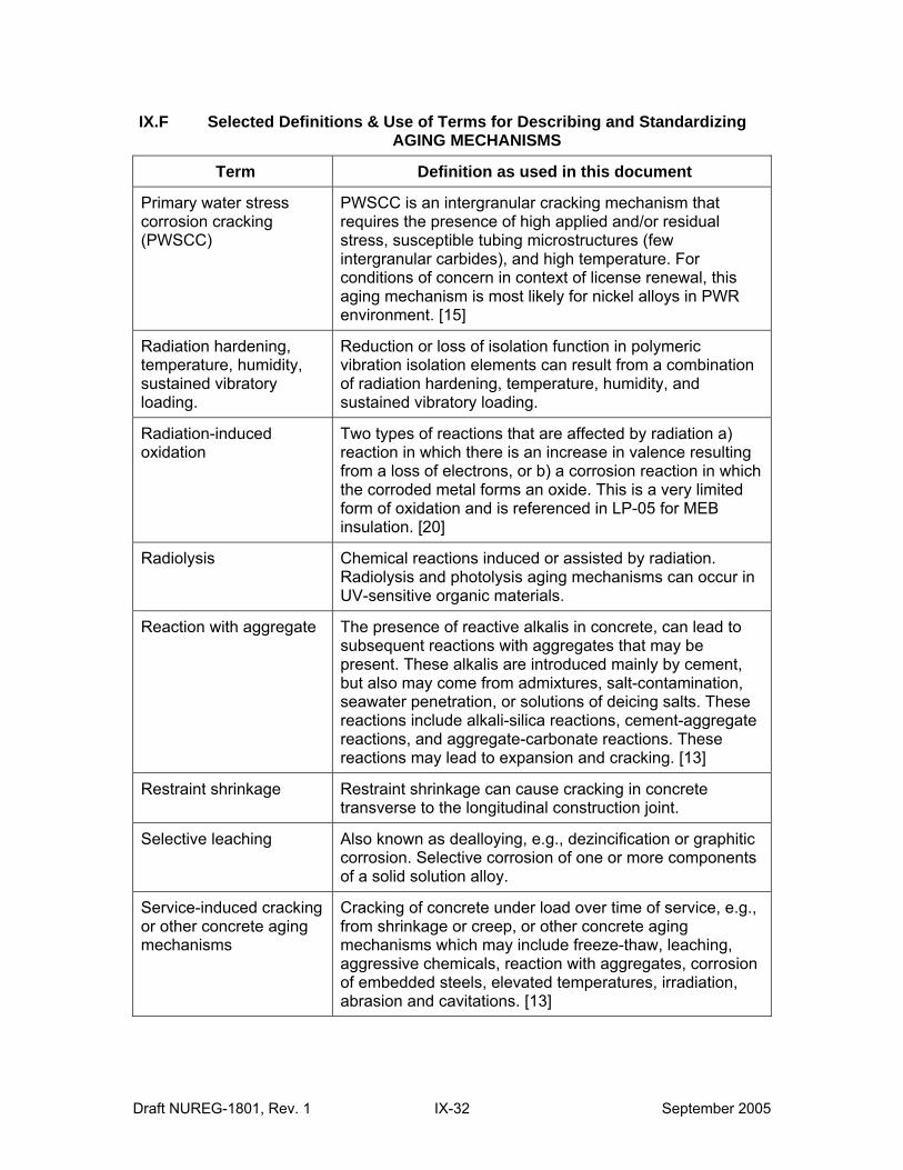
IX.F Selected Definitions & Use of Terms for Describing and Standardizing AGING MECHANISMS
Term Definition as used in this document
Primary water stress corrosion cracking (PWSCC)
PWSCC is an intergranular cracking mechanism that requires the presence of high applied and/or residual stress, susceptible tubing microstructures (few intergranular carbides), and high temperature. For conditions of concern in context of license renewal, this aging mechanism is most likely for nickel alloys in PWR environment. [15]
Radiation hardening, temperature, humidity, sustained vibratory loading.
Reduction or loss of isolation function in polymeric vibration isolation elements can result from a combination of radiation hardening, temperature, humidity, and sustained vibratory loading.
Radiation-induced oxidation
Two types of reactions that are affected by radiation a) reaction in which there is an increase in valence resulting from a loss of electrons, or b) a corrosion reaction in which the corroded metal forms an oxide. This is a very limited form of oxidation and is referenced in LP-05 for MEB insulation. [20]
Radiolysis Chemical reactions induced or assisted by radiation. Radiolysis and photolysis aging mechanisms can occur in UV-sensitive organic materials.
Reaction with aggregate The presence of reactive alkalis in concrete, can lead to subsequent reactions with aggregates that may be present. These alkalis are introduced mainly by cement, but also may come from admixtures, salt-contamination, seawater penetration, or solutions of deicing salts. These reactions include alkali-silica reactions, cement-aggregate reactions, and aggregate-carbonate reactions. These reactions may lead to expansion and cracking. [13]
Restraint shrinkage Restraint shrinkage can cause cracking in concrete transverse to the longitudinal construction joint.
Selective leaching Also known as dealloying, e.g., dezincification or graphitic corrosion. Selective corrosion of one or more components of a solid solution alloy.
Service-induced cracking or other concrete aging mechanisms
Cracking of concrete under load over time of service, e.g., from shrinkage or creep, or other concrete aging mechanisms which may include freeze-thaw, leaching, aggressive chemicals, reaction with aggregates, corrosion of embedded steels, elevated temperatures, irradiation, abrasion and cavitations. [13]
Draft NUREG-1801, Rev. 1 IX-32 September 2005
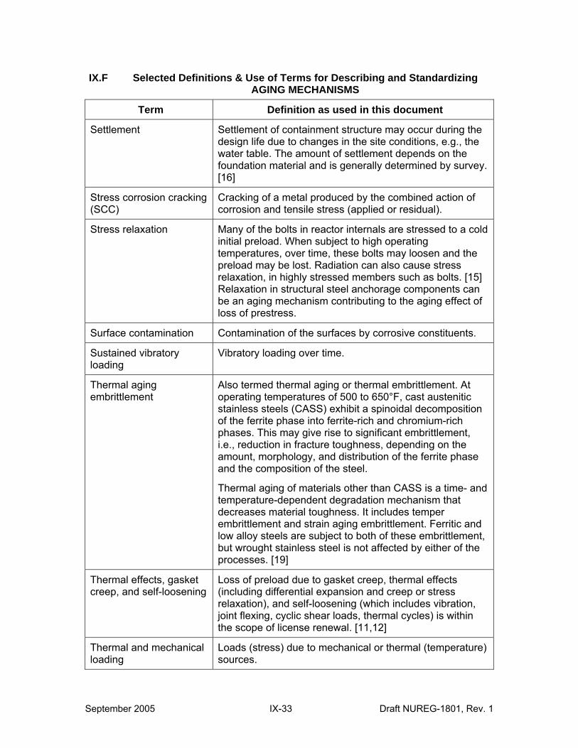
IX.F Selected Definitions & Use of Terms for Describing and Standardizing AGING MECHANISMS
Term Definition as used in this document
Settlement Settlement of containment structure may occur during the design life due to changes in the site conditions, e.g., the water table. The amount of settlement depends on the foundation material and is generally determined by survey. [16]
Stress corrosion cracking (SCC)
Cracking of a metal produced by the combined action of corrosion and tensile stress (applied or residual).
Stress relaxation Many of the bolts in reactor internals are stressed to a cold initial preload. When subject to high operating temperatures, over time, these bolts may loosen and the preload may be lost. Radiation can also cause stress relaxation, in highly stressed members such as bolts. [15] Relaxation in structural steel anchorage components can be an aging mechanism contributing to the aging effect of loss of prestress.
Surface contamination Contamination of the surfaces by corrosive constituents.
Sustained vibratory loading
Vibratory loading over time.
Thermal aging embrittlement
Also termed thermal aging or thermal embrittlement. At operating temperatures of 500 to 650°F, cast austenitic stainless steels (CASS) exhibit a spinoidal decomposition of the ferrite phase into ferrite-rich and chromium-rich phases. This may give rise to significant embrittlement, i.e., reduction in fracture toughness, depending on the amount, morphology, and distribution of the ferrite phase and the composition of the steel.
Thermal aging of materials other than CASS is a time- and temperature-dependent degradation mechanism that decreases material toughness. It includes temper embrittlement and strain aging embrittlement. Ferritic and low alloy steels are subject to both of these embrittlement, but wrought stainless steel is not affected by either of the processes. [19]
Thermal effects, gasket creep, and self-loosening
Loss of preload due to gasket creep, thermal effects (including differential expansion and creep or stress relaxation), and self-loosening (which includes vibration, joint flexing, cyclic shear loads, thermal cycles) is within the scope of license renewal. [11,12]
Thermal and mechanical loading
Loads (stress) due to mechanical or thermal (temperature) sources.
September 2005 IX-33 Draft NUREG-1801, Rev. 1
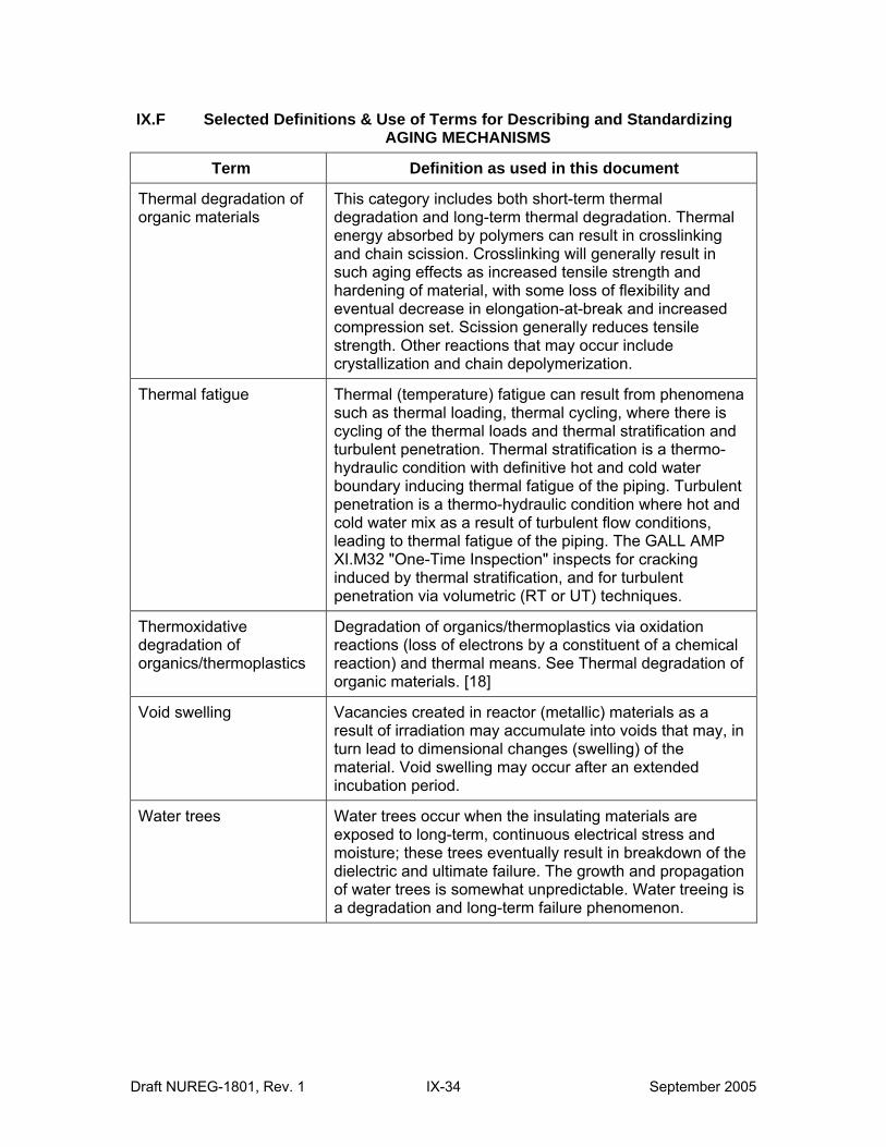
IX.F Selected Definitions & Use of Terms for Describing and Standardizing AGING MECHANISMS
Term Definition as used in this document
Thermal degradation of organic materials
This category includes both short-term thermal degradation and long-term thermal degradation. Thermal energy absorbed by polymers can result in crosslinking and chain scission. Crosslinking will generally result in such aging effects as increased tensile strength and hardening of material, with some loss of flexibility and eventual decrease in elongation-at-break and increased compression set. Scission generally reduces tensile strength. Other reactions that may occur include crystallization and chain depolymerization.
Thermal fatigue Thermal (temperature) fatigue can result from phenomena such as thermal loading, thermal cycling, where there is cycling of the thermal loads and thermal stratification and turbulent penetration. Thermal stratification is a thermohydraulic condition with definitive hot and cold water boundary inducing thermal fatigue of the piping. Turbulent penetration is a thermo-hydraulic condition where hot and cold water mix as a result of turbulent flow conditions, leading to thermal fatigue of the piping. The GALL AMP XI.M32 "One-Time Inspection" inspects for cracking induced by thermal stratification, and for turbulent penetration via volumetric (RT or UT) techniques.
Thermoxidative degradation of organics/thermoplastics
Degradation of organics/thermoplastics via oxidation reactions (loss of electrons by a constituent of a chemical reaction) and thermal means. See Thermal degradation of organic materials. [18]
Void swelling Vacancies created in reactor (metallic) materials as a result of irradiation may accumulate into voids that may, in turn lead to dimensional changes (swelling) of the material. Void swelling may occur after an extended incubation period.
Water trees Water trees occur when the insulating materials are exposed to long-term, continuous electrical stress and moisture; these trees eventually result in breakdown of the dielectric and ultimate failure. The growth and propagation of water trees is somewhat unpredictable. Water treeing is a degradation and long-term failure phenomenon.
Draft NUREG-1801, Rev. 1 IX-34 September 2005
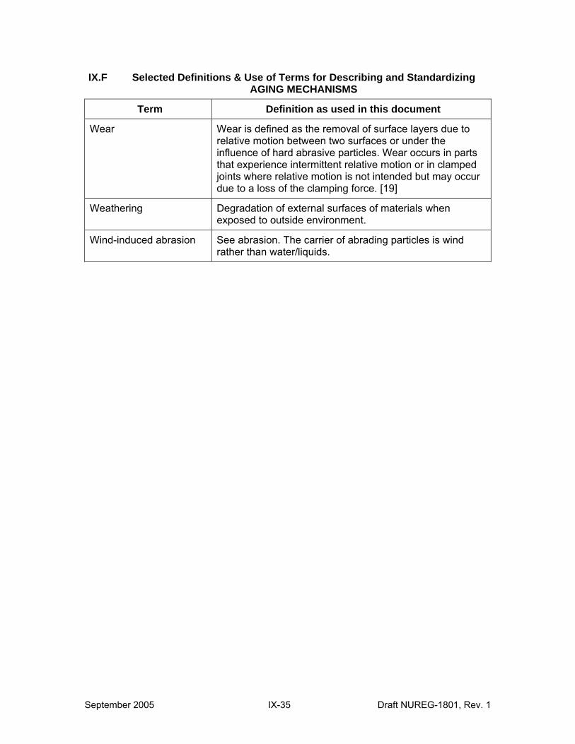
IX.F Selected Definitions & Use of Terms for Describing and Standardizing AGING MECHANISMS
Term Definition as used in this document
Wear Wear is defined as the removal of surface layers due to relative motion between two surfaces or under the influence of hard abrasive particles. Wear occurs in parts that experience intermittent relative motion or in clamped joints where relative motion is not intended but may occur due to a loss of the clamping force. [19]
Weathering Degradation of external surfaces of materials when exposed to outside environment.
Wind-induced abrasion See abrasion. The carrier of abrading particles is wind rather than water/liquids.
September 2005 IX-35 Draft NUREG-1801, Rev. 1
G. References:
1. SAND 93-7070, “Aging Management Guideline for Commercial Nuclear Power Plants – Heat Exchangers,” Sandia National Laboratories, June 1994.
2. ASME Boiler & Pressure Vessel Code, Section II: Part B, Nonferrous Material Specifications
3. ASME Boiler & Pressure Vessel Code, Section II: Part A, Ferrous Material Specification
4. Gillen and Clough, Rad. Phys. Chem Vol. 18, p. 679, 1981
5. D. Peckner and I. M. Bernstein, Eds., Handbook of Stainless Steels, McGraw-Hill, New York, 1977, p. 16-85.
6. Metals Handbook, Ninth Edition, Volume 13, Corrosion, American Society of Metals, 1987, p. 326
7. O. K. Chopra and A. Sather, “Initial Assessment of the Mechanisms and Significance of Low-Temperature Embrittlement of Cast Stainless Steels in LWR Systems,” NUREG/CR-5385 (ANL-89/17) Argonne National Laboratory, Argonne, IL (August 1990).
8. NUREG-1557, “Summary of Technical Information and Agreements from Nuclear Management and Resources Council Industry Reports Addressing License Renewal,” October 1996.
9. NUREG-1760, “Aging Assessment of Safety-Related Fuses Used in Low- and Medium-Voltage Applications in Nuclear Power Plants,” May 2002.
10. SAND96-0344, “Aging Management Guideline for Commercial Nuclear Power Plants – Electrical Cable and Terminations,” September 1996.
11. EPRI TR-104213, “Bolted Joint Maintenance & Application Guide,” Electric Power Research Institute, Palo Alto, CA, December 1995.
12. EPRI NP-5067, "Good Bolting Practices, A Reference Manual for Nuclear Power Plant Maintenance Personnel," volume 1: "Large Bolt Manual," 1987 and volume 2: "Small Bolts and Threaded Fasteners," 1990.
13. NUMARC Report 90-06, Revision 1, December 1991, "Class 1 Structures License Renewal Industry Report,” NUMARC, Washington D.C.
14. NRC GL 96-04: “Boraflex Degradation in Spent Fuel Pool Storage Racks,” NRC, Rockville, MD, 1996.
15. V. N. Shah and D. E. Macdonald, Eds., "Aging and Life Extension of Major Light Water Reactor Components,” Elsevier, Amsterdam, 1993.
16. M. Gavrilas, P. Hejzlar, N.E. Todreas, and Y. Shatilla, "Safety Features of Operating Light Water Reactors of Western Designs," CANES, MIT, Cambridge, MA, 2000.
Draft NUREG-1801, Rev. 1 IX-36 September 2005
17. NUMARC Report 90-01, Revision 1, Sept 1991, "Pressurized Water Reactors Containment Structures License Renewal Industry Report,” NUMARC, Washington D.C.
18. 1976 Annual Book of ASTM Standards, Part 10, ASTM, Philadelphia, PA, 1976.
19. NUMARC Report 90-07, May 1992, "PWR Reactor Coolant System License Renewal Industry Report,” NUMARC, Washington D.C.
20. J. R. Davis (Editor) "Corrosion," ASM International, Materials Park, OH, 2000.
21. 2004 Annual Book of ASTM Standards, Volume 09.01, ASTM International, 2004.
22. NUMARC Report 90-05, Revision 1, December 1992, "PWR Reactor Pressure Vessel Internals License Renewal Industry Report,” Washington D.C.
23. NSAC-202L-R2, “Recommendations for an Effective Flow Accelerated Corrosion Program,” Electric Power Research Institute, Palo Alto, CA, April 8, 1999.
24.ACI 301-84 “Specification for Structural Concrete for Buildings,” (Field Reference Manual) American Concrete Institute, Detroit, MI, Revised 1988.
25.ACI 201.2R 77 “Guide to Durable Concrete,” American Concrete Institute, Detroit, MI, Reapproved 1982.
September 2005 IX-37 Draft NUREG-1801, Rev. 1
This Page Intentionally Left Blank
Draft NUREG-1801, Rev. 1 IX-38 September 2005
CHAPTER X
TIME-LIMITED AGING ANALYSES EVALUATION OF AGING MANAGEMENT PROGRAMS
UNDER 10 CFR 54.21(c)(1)(iii)
September 2005 X-i Draft NUREG-1801, Rev. 1

This Page Intentionally Left Blank
Draft NUREG-1801, Rev. 1 X-ii September 2005

TIME-LIMITED AGING ANALYSES: EVALUATION OF AGING MANAGEMENT PROGRAMS UNDER 10 CFR 54.21(c)(1)(iii)
X.M1 Metal Fatigue of Reactor Coolant Pressure Boundary
X.S1 Concrete Containment Tendon Prestress
X.E1 Environmental Qualification (EQ) of Electrical Components
September 2005 X-iii Draft NUREG-1801, Rev. 1

This Page Intentionally Left Blank
Draft NUREG-1801, Rev. 1 X-iv September 2005
X.M1 METAL FATIGUE OF REACTOR COOLANT PRESSURE BOUNDARY
Program Description
In order not to exceed the design limit on fatigue usage, the aging management program (AMP) monitors and tracks the number of critical thermal and pressure transients for the selected reactor coolant system components.
The AMP addresses the effects of the coolant environment on component fatigue life by assessing the impact of the reactor coolant environment on a sample of critical components for the plant. Examples of critical components are identified in NUREG/CR-6260. The sample of critical components can be evaluated by applying environmental life correction factors to the existing ASME Code fatigue analyses. Formulae for calculating the environmental life correction factors are contained in NUREG/CR-6583 for carbon and low-alloy steels and in NUREG/CR-5704 for austenitic stainless steels.
As evaluated below, this is an acceptable option for managing metal fatigue for the reactor coolant pressure boundary, considering environmental effects. Thus, no further evaluation is recommended for license renewal if the applicant selects this option under 10 CFR 54.21(c)(1)(iii) to evaluate metal fatigue for the reactor coolant pressure boundary.
Evaluation and Technical Basis
1. Scope of Program: The program includes preventive measures to mitigate fatigue cracking of metal components of the reactor coolant pressure boundary caused by anticipated cyclic strains in the material.
2. Preventive Actions: Maintaining the fatigue usage factor below the design code limit and considering the effect of the reactor water environment, as described under the program description, will provide adequate margin against fatigue cracking of reactor coolant system components due to anticipated cyclic strains.
3. Parameters Monitored/Inspected: The program monitors all plant transients that cause cyclic strains, which are significant contributors to the fatigue usage factor. The number of plant transients that cause significant fatigue usage for each critical reactor coolant pressure boundary component is to be monitored. Alternatively, more detailed local monitoring of the plant transient may be used to compute the actual fatigue usage for each transient.
4. Detection of Aging Effects: The program provides for periodic update of the fatigue usage calculations.
5. Monitoring and Trending: The program monitors a sample of high fatigue usage locations. This sample is to include the locations identified in NUREG/CR-6260 and any additional critical components in the plant.
6. Acceptance Criteria: The acceptance criteria involves maintaining the fatigue usage below the design code limit considering environmental fatigue effects as described under the program description.
7. Corrective Actions: The program provides for corrective actions to prevent the usage factor from exceeding the design code limit during the period of extended operation.
September 2005 X M-1 Draft NUREG-1801, Rev. 1
Acceptable corrective actions include repair of the component, replacement of the component, and a more rigorous analysis of the component to demonstrate that the design code limit will not be exceeded during the extended period of operation. For programs that monitor a sample of high fatigue usage locations, corrective actions include a review of additional affected reactor coolant pressure boundary locations. As discussed in the appendix to this report, the staff finds the requirements of 10 CFR Part 50, Appendix B, acceptable to address the corrective actions.
8. Conformation Process: Site quality assurance procedures, review and approval processes, and administrative controls are implemented in accordance with the requirements of Appendix B to 10 CFR Part 50. As discussed in the appendix to this report, the staff finds the requirements of 10 CFR Part 50, Appendix B, acceptable to address the confirmation process and administrative controls.
9. Administrative Controls: See Item 8, above.
10. Operating Experience: The program reviews industry experience regarding fatigue cracking. Applicable experience with fatigue cracking is to be considered in selecting the monitored locations.
References
NUREG/CR-5704, Effects of LWR Coolant Environments on Fatigue Design Curves of Austenitic Stainless Steels, U.S. Nuclear Regulatory Commission, April 1999.
NUREG/CR-6260, Application of NUREG/CR-5999 Interim Fatigue Curves to Selected Nuclear Power Plant Components, U.S. Nuclear Regulatory Commission, March 1995.
NUREG/CR-6583, Effects of LWR Coolant Environments on Fatigue Design Curves of Carbon and Low-Alloy Steels, U.S. Nuclear Regulatory Commission, March 1998.
Draft NUREG-1801, Rev. 1 X M-2 September 2005
X.S1 CONCRETE CONTAINMENT TENDON PRESTRESS
Program Description
In order to ensure the adequacy of prestressing forces in prestressed concrete containment tendons during the extended period of operation, an applicant shall develop an aging management program (AMP) under 10 CFR 54.21(c)(1)(iii).
The AMP consists of an assessment of the results of inspections performed in accordance with the requirements of Subsection IWL of the ASME Section XI Code, as supplemented by the requirements of 10 CFR 50.55a(b)(2)(ix) or (viii) in the later amendment of the regulation. The assessment related to the adequacy of the prestressing force will consist of the establishment of (1) acceptance criteria and (2) trend lines. The acceptance criteria will normally consist of predicted lower limit (PLL) and the minimum required prestressing force, also called minimum required value (MRV). NRC Regulatory Guide 1.35.1 provides guidance for calculating PLL and MRV. The trend line represents the trend of prestressing forces based on the actual measured forces. NRC Information Notice IN 99-10 provides guidance for constructing the trend line. The goal is to keep the trend line above the PLL because, as a result of any inspection performed in accordance with ASME Section XI, Subsection IWL, if the trend line crosses the PLL, the existing prestress in the containment tendon could go below the MRV soon after the inspection and would not meet the requirements of 10 CFR 50.55a(b)(2)(ix)(B) or 10 CFR 50.55a(b)(2)(viii)(B).
As evaluated below, this time limited aging analysis (TLAA) is an acceptable option to manage containment tendon prestress force, except for the program element/attribute regarding operating experience. Thus, it is recommended that the staff should further evaluate an applicant's operating experience related to the containment tendon prestress force.
The AMP related to the adequacy of prestressing force for containments with grouted tendons will be reviewed on a case-by-case basis.
Evaluation and Technical Basis
1. Scope of Program: The program addresses the assessment of containment tendon prestressing force when an applicant chooses to perform the containment prestress force TLAA using 10 CFR 54.21(c)(1)(iii).
2. Preventive Actions: Maintaining the prestress above the MRV, as described under program description above, will ensure that the structural and functional adequacy of the containment are maintained.
3. Parameters Monitored: The parameters to be monitored are the containment tendon prestressing forces in accordance with requirements specified in Subsection IWL of Section XI of the ASME Code, as incorporated by reference in 10 CFR 50.55a.
4. Detection of Aging Effects: The loss of containment tendon prestressing forces is detected by the program.
5. Monitoring and Trending: The estimated and measured prestressing forces are plotted against time and the PLL, MRV, and trending lines developed for the period of extended operation.
September 2005 X S-1 Draft NUREG-1801, Rev. 1
6. Acceptance Criteria: The prestressing force trend lines indicate that existing prestressing forces in the containment tendon would not be below the MRVs prior to the next scheduled inspection, as required by 10 CFR 50.55a(b)(2)(ix)(B) or 10 CFR 50.55a(b)(2)(viii)(B).
7. Corrective Actions: If acceptance criteria are not met, then either systematic retensioning of tendons or a reanalysis of the containment is warranted to ensure the design adequacy of the containment. As discussed in the appendix to this report, the staff finds the requirements of 10 CFR Part 50, Appendix B, acceptable to address the corrective actions.
8. Conformation Process: As discussed in the appendix to this report, the staff finds the requirements of 10 CFR Part 50, Appendix B, acceptable to address the confirmation process.
9. Administrative Controls: As discussed in the appendix to this report, the staff finds the requirements of 10 CFR Part 50, Appendix B, acceptable to address the administrative controls.
10. Operating Experience: The program incorporates the relevant operating experience that has occurred at the applicant's plant as well as at other plants. The applicable portions of the experience with prestressing systems described in NRC Information Notice 99-10 could be useful for the purpose. However, tendon operating experience could be different at plants with prestressed concrete containments. The difference could be due to the prestressing system design (e.g., button-headed, wedge, or swaged anchorages), environment, and type of reactor (i.e., PWR and BWR). Thus, the applicant's plant-specific operating experience should be further evaluated for license renewal.
References
ASME Section XI, Rules for In-Service Inspection of Nuclear Power Plant Components, Subsection IWL, Requirements for Class CC Concrete Components of Light-Water Cooled Plants, 1992 Edition with 1992 Addenda, The ASME Boiler and Pressure Vessel Code, The American Society of Mechanical Engineers, New York, NY.
ASME Section XI, Rules for In-Service Inspection of Nuclear Power Plant Components, Subsection IWL, Requirements for Class CC Concrete Components of Light-Water Cooled Plants, 1995 Edition with 1996 Addenda, The ASME Boiler and Pressure Vessel Code, The American Society of Mechanical Engineers, New York, NY.
NRC Information Notice 99-10, Degradation of Prestressing Tendon Systems in Prestressed Concrete Containments, U. S. Nuclear Regulatory Commission, April 1999.
NRC Regulatory Guide 1.35.1, Determining Prestressing Forces for Inspection of Prestressed Concrete Containments, U. S. Nuclear Regulatory Commission, July 1990.
Draft NUREG-1801, Rev. 1 X S-2 September 2005
X.E1 ENVIRONMENTAL QUALIFICATION (EQ) OF ELECTRIC COMPONENTS
Program Description
The Nuclear Regulatory Commission (NRC) has established nuclear station environmental qualification (EQ) requirements in 10 CFR Part 50, Appendix A, Criterion 4, and 10 CFR 50.49. 10 CFR 50.49 specifically requires that an EQ program be established to demonstrate that certain electrical components located in harsh plant environments (that is, those areas of the plant that could be subject to the harsh environmental effects of a loss of coolant accident [LOCA], high energy line breaks [HELBs] or post-LOCA environment) are qualified to perform their safety function in those harsh environments after the effects of inservice aging. 10 CFR 50.49 requires that the effects of significant aging mechanisms be addressed as part of environmental qualification.
All operating plants must meet the requirements of 10 CFR 50.49 for certain electrical components important to safety. 10 CFR 50.49 defines the scope of components to be included, requires the preparation and maintenance of a list of in-scope components, and requires the preparation and maintenance of a qualification file that includes component performance specifications, electrical characteristics, and the environmental conditions to which the components could be subjected. 10 CFR 50.49(e)(5) contains provisions for aging that require, in part, consideration of all significant types of aging degradation that can affect component functional capability. 10 CFR 50.49(e) also requires replacement or refurbishment of components not qualified for the current license term prior to the end of designated life, unless additional life is established through ongoing qualification. 10 CFR 50.49(f) establishes four methods of demonstrating qualification for aging and accident conditions. 10 CFR 50.49(k) and (l) permit different qualification criteria to apply based on plant and component vintage. Supplemental EQ regulatory guidance for compliance with these different qualification criteria is provided in the DOR Guidelines, Guidelines for Evaluating Environmental Qualification of Class 1E Electrical Equipment in Operating Reactors; NUREG-0588, Interim Staff Position on Environmental Qualification of Safety-Related Electrical Equipment; and Regulatory Guide 1.89, Rev. 1, Environmental Qualification of Certain Electric Equipment Important to Safety for Nuclear Power Plants. Compliance with 10 CFR 50.49 provides reasonable assurance that the component can perform its intended functions during accident conditions after experiencing the effects of inservice aging.
EQ programs manage component thermal, radiation, and cyclical aging through the use of aging evaluations based on 10 CFR 50.49(f) qualification methods. As required by 10 CFR 50.49, EQ components not qualified for the current license term are to be refurbished, replaced, or have their qualification extended prior to reaching the aging limits established in the evaluation. Aging evaluations for EQ components that specify a qualification of at least 40 years are considered time-limited aging analyses (TLAAs) for license renewal.
Under 10 CFR 54.21(c)(1)(iii), plant EQ programs, which implement the requirements of 10 CFR 50.49 (as further defined and clarified by the DOR Guidelines, NUREG-0588, and Regulatory Guide 1.89, Rev. 1), are viewed as aging management programs (AMPs) for license renewal. Reanalysis of an aging evaluation to extend the qualification of components under 10 CFR 50.49(e) is performed on a routine basis as part of an EQ program. Important attributes for the reanalysis of an aging evaluation include analytical methods, data collection and reduction methods, underlying assumptions, acceptance criteria, and corrective actions (if acceptance criteria are not met). These attributes are discussed in the "EQ Component Reanalysis Attributes" section.
September 2005 X E-1 Draft NUREG-1801, Rev. 1
This reanalysis program can be applied to EQ components now qualified for the current operating term (i.e., those components now qualified for 40 years or more). As evaluated below, this is an acceptable AMP. Thus, no further evaluation is recommended for license renewal if an applicant elects this option under 10 CFR 54.21(c)(1)(iii) to evaluate the TLAA of EQ of electric equipment.
EQ Component Reanalysis Attributes
The reanalysis of an aging evaluation is normally performed to extend the qualification by reducing excess conservatism incorporated in the prior evaluation. Reanalysis of an aging evaluation to extend the qualification of a component is performed on a routine basis pursuant to 10 CFR 50.49(e) as part of an EQ program. While a component life limiting condition may be due to thermal, radiation, or cyclical aging, the vast majority of component aging limits are based on thermal conditions. Conservatism may exist in aging evaluation parameters, such as the assumed ambient temperature of the component, an unrealistically low activation energy, or in the application of a component (de-energized versus energized). The reanalysis of an aging evaluation is documented according to the station's quality assurance program requirements, which requires the verification of assumptions and conclusions. As already noted, important attributes of a reanalysis include analytical methods, data collection and reduction methods, underlying assumptions, acceptance criteria, and corrective actions (if acceptance criteria are not met). These attributes are discussed below.
Analytical Methods: The analytical models used in the reanalysis of an aging evaluation are the same as those previously applied during the prior evaluation. The Arrhenius methodology is an acceptable thermal model for performing a thermal aging evaluation. The analytical method used for a radiation aging evaluation is to demonstrate qualification for the total integrated dose (that is, normal radiation dose for the projected installed life plus accident radiation dose). For license renewal, one acceptable method of establishing the 60-year normal radiation dose is to multiply the 40-year normal radiation dose by 1.5 (that is, 60 years/40 years). The result is added to the accident radiation dose to obtain the total integrated dose for the component. For cyclical aging, a similar approach may be used. Other models may be justified on a case-by-case basis.
Data Collection and Reduction Methods: Reducing excess conservatism in the component service conditions (for example, temperature, radiation, cycles) used in the prior aging evaluation is the chief method used for a reanalysis. Temperature data used in an aging evaluation is to be conservative and based on plant design temperatures or on actual plant temperature data. When used, plant temperature data can be obtained in several ways, including monitors used for technical specification compliance, other installed monitors, measurements made by plant operators during rounds, and temperature sensors on large motors (while the motor is not running). A representative number of temperature measurements are conservatively evaluated to establish the temperatures used in an aging evaluation. Plant temperature data may be used in an aging evaluation in different ways, such as (a) directly applying the plant temperature data in the evaluation, or (b) using the plant temperature data to demonstrate conservatism when using plant design temperatures for an evaluation. Any changes to material activation energy values as part of a reanalysis are to be justified on a plant-specific basis. Similar methods of reducing excess conservatism in the component service conditions used in prior aging evaluations can be used for radiation and cyclical aging.
Draft NUREG-1801, Rev. 1 X E-2 September 2005
Underlying Assumptions: EQ component aging evaluations contain sufficient conservatism to account for most environmental changes occurring due to plant modifications and events. When unexpected adverse conditions are identified during operational or maintenance activities that affect the normal operating environment of a qualified component, the affected EQ component is evaluated and appropriate corrective actions are taken, which may include changes to the qualification bases and conclusions.
Acceptance Criteria and Corrective Actions: The reanalysis of an aging evaluation could extend the qualification of the component. If the qualification cannot be extended by reanalysis, the component is to be refurbished, replaced, or requalified prior to exceeding the period for which the current qualification remains valid. A reanalysis is to be performed in a timely manner (that is, sufficient time is available to refurbish, replace, or requalify the component if the reanalysis is unsuccessful).
Evaluation and Technical Basis
1. Scope of Program: EQ programs apply to certain electrical components that are important to safety and could be exposed to harsh environment accident conditions, as defined in 10 CFR 50.49 and Regulatory Guide 1.89, Rev.1.
2. Preventive Actions: 10 CFR 50.49 does not require actions that prevent aging effects. EQ program actions that could be viewed as preventive actions include (a) establishing the component service condition tolerance and aging limits (for example, qualified life or condition limit) and (b) where applicable, requiring specific installation, inspection, monitoring or periodic maintenance actions to maintain component aging effects within the bounds of the qualification basis.
3. Parameters Monitored/Inspected: EQ component qualified life is not based on condition or performance monitoring. However, pursuant to Regulatory Guide 1.89, Rev. 1, such monitoring programs are an acceptable basis to modify a qualified life through reanalysis. Monitoring or inspection of certain environmental conditions or component parameters may be used to ensure that the component is within the bounds of its qualification basis, or as a means to modify the qualified life.
4. Detection of Aging Effects: 10 CFR 50.49 does not require the detection of aging effects for in-service components. Monitoring or inspection of certain environmental conditions or component parameters may be used to ensure that the component is within the bounds of its qualification basis, or as a means to modify the qualified life.
5. Monitoring and Trending: 10 CFR 50.49 does not require monitoring and trending of component condition or performance parameters of in-service components to manage the effects of aging. EQ program actions that could be viewed as monitoring include monitoring how long qualified components have been installed. Monitoring or inspection of certain environmental, condition, or component parameters may be used to ensure that a component is within the bounds of its qualification basis, or as a means to modify the qualification.
6. Acceptance Criteria: 10 CFR 50.49 acceptance criteria are that an inservice EQ component is maintained within the bounds of its qualification basis, including (a) its established qualified life and (b) continued qualification for the projected accident conditions. 10 CFR 50.49 requires refurbishment, replacement, or requalification prior to exceeding the
September 2005 X E-3 Draft NUREG-1801, Rev. 1
qualified life of each installed device. When monitoring is used to modify a component qualified life, plant-specific acceptance criteria are established based on applicable 10 CFR 50.49(f) qualification methods.
7. Corrective Actions: If an EQ component is found to be outside the bounds of its qualification basis, corrective actions are implemented in accordance with the station's corrective action program. When unexpected adverse conditions are identified during operational or maintenance activities that affect the environment of a qualified component, the affected EQ component is evaluated and appropriate corrective actions are taken, which may include changes to the qualification bases and conclusions. When an emerging industry aging issue is identified that affects the qualification of an EQ component, the affected component is evaluated and appropriate corrective actions are taken, which may include changes to the qualification bases and conclusions. Confirmatory actions, as needed, are implemented as part of the station's corrective action program, pursuant to 10 CFR 50, Appendix B. As discussed in the appendix to this report, the staff finds the requirements of 10 CFR Part 50, Appendix B, acceptable to address the corrective actions.
8. Confirmation Process: Confirmatory actions, as needed, are implemented as part of the station's corrective action program, pursuant to 10 CFR 50, Appendix B. As discussed in the appendix to this report, the staff finds the requirements of 10 CFR Part 50, Appendix B, acceptable to address the confirmation process.
9. Administrative Controls: EQ programs are implemented through the use of station policy, directives, and procedures. EQ programs will continue to comply with 10 CFR 50.49 throughout the renewal period, including development and maintenance of qualification documentation demonstrating reasonable assurance that a component can perform required functions during harsh accident conditions. EQ program documents identify the applicable environmental conditions for the component locations. EQ program qualification files are maintained at the plant site in an auditable form for the duration of the installed life of the component. EQ program documentation is controlled under the station's quality assurance program. As discussed in the appendix to this report, the staff finds the requirements of 10 CFR Part 50, Appendix B, acceptable to address the administrative controls.
10. Operating Experience: EQ programs include consideration of operating experience to modify qualification bases and conclusions, including qualified life. Compliance with 10 CFR 50.49 provides reasonable assurance that components can perform their intended functions during accident conditions after experiencing the effects of inservice aging.
References
10 CFR 50.49, Environmental Qualification of Electric Equipment Important to Safety for Nuclear Power Plants, Office of the Federal Register, National Archives and Records Administration, 2005.
DOR Guidelines, Guidelines for Evaluating Environmental Qualification of Class 1E Electrical Equipment in Operating Reactors, November 1979.
NRC Regulatory Guide 1.89, Rev. 1, Environmental Qualification of Certain Electric Equipment Important to Safety for Nuclear Power Plants, U. S. Nuclear Regulatory Commission, June 1984.
Draft NUREG-1801, Rev. 1 X E-4 September 2005
NUREG-0588, Interim Staff Position on Environmental Qualification of Safety-Related Electrical Equipment, U. S. Nuclear Regulatory Commission, July 1981.
NRC Regulatory Issue Summary 2003-09, “Environmental Qualification of Low-Voltage Instrumentation and Control Cables” dated May 2, 2003.
September 2005 X E-5 Draft NUREG-1801, Rev. 1

This Page Intentionally Left Blank
Draft NUREG-1801, Rev. 1 X E-6 September 2005
CHAPTER XI
AGING MANAGEMENT PROGRAMS (AMPs)
September 2005 XI M-i Draft NUREG-1801, Rev. 1

This Page Intentionally Left Blank
Draft NUREG-1801, Rev. 1 XI M-ii September 2005
AGING MANAGEMENT PROGRAMS (AMPs)
XI.M1 ASME Section XI Inservice Inspection, Subsections IWB, IWC, and IWD XI.M2 Water Chemistry XI.M3 Reactor Head Closure Studs XI.M4 BWR Vessel ID Attachment Welds XI.M5 BWR Feedwater Nozzle XI.M6 BWR Control Rod Drive Return Line Nozzle XI.M7 BWR Stress Corrosion Cracking XI.M8 BWR Penetrations XI.M9 BWR Vessel Internals XI.M10 Boric Acid Corrosion XI.M11 Nickel-Alloy Nozzles and Penetrations (Deleted) XI.M11A Nickel-Alloy Penetration Nozzles Welded to the Upper Reactor Vessel Closure
Heads of Pressurized Water Reactors XI.M12 Thermal Aging Embrittlement of Cast Austenitic Stainless Steel (CASS) XI.M13 Thermal Aging and Neutron Irradiation Embrittlement of Cast Austenitic Stainless
Steel (CASS) XI.M14 Loose Part Monitoring XI.M15 Neutron Noise Monitoring XI.M16 PWR Vessel Internals (Deleted) XI.M17 Flow-Accelerated Corrosion XI.M18 Bolting Integrity XI.M19 Steam Generator Tube Integrity XI.M20 Open-Cycle Cooling Water System XI.M21 Closed-Cycle Cooling Water System XI.M22 Boraflex Monitoring XI.M23 Inspection of Overhead Heavy Load and Light Load (Related to Refueling)
Handling Systems XI.M24 Compressed Air Monitoring XI.M25 BWR Reactor Water Cleanup System XI.M26 Fire Protection XI.M27 Fire Water System XI.M28 Buried Piping and Tanks Surveillance XI.M29 Aboveground Steel Tanks XI.M30 Fuel Oil Chemistry XI.M31 Reactor Vessel Surveillance XI.M32 One-Time Inspection XI.M33 Selective Leaching of Materials XI.M34 Buried Piping and Tanks Inspection XI.M35 One-time Inspection of ASME Code Class 1 Small Bore-Piping XI.M36 External Surfaces Monitoring XI.M37 Flux Thimble Tube Inspection XI.M38 Inspection of Internal Surfaces in Miscellaneous Piping and Ducting Components XI.M39 Lubricating Oil Analysis XI.S1 ASME Section XI, Subsection IWE XI.S2 ASME Section XI, Subsection IWL XI.S3 ASME Section XI, Subsection IWF XI.S4 10 CFR Part 50, Appendix J
September 2005 XI M-iii Draft NUREG-1801, Rev. 1
AGING MANAGEMENT PROGRAMS (AMPs) (Continued)
XI.S5 Masonry Wall Program XI.S6 Structures Monitoring Program XI.S7 RG 1.127, Inspection of Water-Control Structures Associated with Nuclear Power
Plants XI.S8 Protective Coating Monitoring and Maintenance Program XI.E1 Electrical Cables and Connections Not Subject to 10 CFR 50.49 Environmental
Qualification Requirements XI.E2 Electrical Cables and Connections Not Subject to 10 CFR 50.49 Environmental
Qualification Requirements Used in Instrumentation Circuits XI.E3 Inaccessible Medium Voltage Cables Not Subject to 10 CFR 50.49 Environmental
Qualification Requirements XI.E4 Metal-Enclosed Bus XI.E5 Fuse Holders XI.E6 Electrical Cable Connections Not Subject to 10 CFR 50.49 Environmental
Qualification Requirements
Draft NUREG-1801, Rev. 1 XI M-iv September 2005
XI.M1 ASME SECTION XI INSERVICE INSPECTION, SUBSECTIONS IWB, IWC, AND IWD
Program Description
Title 10 of the Code of Federal Regulations, 10 CFR 50.55a, imposes the inservice inspection (ISI) requirements of the American Society of Mechanical Engineers (ASME) Boiler and Pressure Vessel (B&PV) Code, Section XI, for Class 1, 2, and 3 pressure-retaining components and their integral attachments in light-water cooled power plants. Inspection, repair, and replacement of these components are covered in Subsections IWB, IWC, and IWD, respectively, in the 2001 edition1 including the 2002 and 2003 Addenda. The program generally includes periodic visual, surface, and/or volumetric examination and leakage test of all Class 1, 2, and 3 pressure-retaining components and their integral attachments.
The ASME Section XI inservice inspection program in accordance with Subsections IWB, IWC, or IWD has been shown to be generally effective in managing aging effects in Class 1, 2, or 3 components and their integral attachments in light-water cooled power plants. However, in certain cases, the ASME inservice inspection program is to be augmented to manage effects of aging for license renewal and is so identified in the GALL Report.
Evaluation and Technical Basis
1. Scope of Program: The ASME Section XI program provides the requirements for ISI, repair, and replacement. The components within the scope of the program are specified in Subsections IWB-1100, IWC-1100, and IWD-1100 for Class 1, 2, and 3 components, respectively, and include all pressure-retaining components and their integral attachments in light-water cooled power plants. The components described in Subsections IWB-1220, IWC-1220, and IWD-1220 are exempt from the examination requirements of Subsections IWB-2500, IWC-2500, and IWD-2500.
2. Preventive Actions: Operation within the limits prescribed in the Technical Specifications.
3. Parameters Monitored/Inspected: The ASME Section XI ISI program detects degradation of components by using the examination and inspection requirements specified in ASME Section XI Tables IWB-2500-1, IWC-2500-1, or IWD-2500-1, respectively, for Class 1, 2, or 3 components.
4. Detection of Aging Effects: The extent and schedule of the inspection and test techniques prescribed by the program are designed to maintain structural integrity and ensure that aging effects will be discovered and repaired before the loss of intended function of the component. Inspection can reveal cracking, loss of material due to corrosion, leakage of coolant and indications of degradation due to wear or stress relaxation, such as verification of clearances, settings, physical displacements, loose or missing parts, debris, wear, erosion, or loss of integrity at bolted or welded connections.
1 An applicant may rely on a different version of the ASME Code, but should justify such use. An applicant may wish to refer to the SOC for an update of 10 C.F.R. § 50.55a to justify use of a more recent edition of the Code.
September 2005 XI M-5 Draft NUREG-1801, Rev. 1

Components are examined and tested as specified in Tables IWB-2500-1, IWC-2500-1, and IWD-2500-1, respectively, for Class 1, 2, and 3 components. The tables specify the extent and schedule of the inspection and examination methods for the components of the pressure-retaining boundaries. Alternative approved methods that meet the requirements of IWA-2240 are also specified in these tables.
The program uses three types of examination — visual, surface, and volumetric — in accordance with the general requirements of Subsection IWA-2000. Visual VT-1 examination detects discontinuities and imperfections, such as cracks, corrosion, wear, or erosion, on the surface of components. Visual VT-2 examination detects evidence of leakage from pressure-retaining components, as required during the system pressure test. Visual VT-3 examination (a) determines the general mechanical and structural condition of components and their supports by verifying parameters such as clearances, settings, and physical displacements; (b) detects discontinuities and imperfections such as loss of integrity at bolted or welded connections, loose or missing parts, debris, corrosion, wear, or erosion; and (c) observes conditions that could affect operability or functional adequacy of constant-load and spring-type components and supports.
Surface examination uses magnetic particle, liquid penetrant, or eddy current examinations to indicate the presence of surface discontinuities and flaws.
Volumetric examination uses radiographic, ultrasonic, or eddy current examinations to indicate the presence of discontinuities or flaws throughout the volume of material included in the inspection program.
For BWRs, the nondestructive examination (NDE) techniques appropriate for inspection of vessel internals, including the uncertainties inherent in delivering and executing an NDE technique in a boiling water reactor (BWR), are included in the approved boiling water reactor vessel and internals project (BWRVIP)-03. Also, an applicant may use the guidelines of the approved BWRVIP-62 for inspection relief for vessel internal components with hydrogen water chemistry provided such relief is submitted under the provisions of 10 CFR 50.55a and approved by the staff.
The ASME Section XI examination categories used in this report are given below.
Class 1 Components, Table IWB-2500-1
Examination category B-B for pressure-retaining welds in vessels other than reactor vessels: This category specifies volumetric examination of circumferential and longitudinal shell-to-head welds and circumferential and meridional head welds in pressurizers, and circumferential and meridional head welds and tubesheet-to-head welds in steam generators (primary side). The welds selected during the first inspection interval are reexamined during successive inspection intervals. Examination category B-D for full penetration welds of nozzles in reactor vessels, pressurizers, steam generators (primary side), and heat exchangers (primary side): This category specifies volumetric examination of all nozzle-to-vessel welds and the nozzle inside surface.
Draft NUREG-1801, Rev. 1 XI M-6 September 2005
Examination category B-E for pressure-retaining partial penetration welds in vessels: This category specifies visual VT-2 examination of partial penetration welds in nozzles and penetrations in reactor vessels and pressurizers during the hydrostatic test. In the 1995 edition of the ASME Code, examination category B-E is covered under examination category B-P.
Examination category B-F for pressure-retaining dissimilar metal welds in reactor vessels, pressurizers, steam generators, heat exchangers, and piping: This category specifies volumetric examination of the inside diameter (ID) region and surface examination of the outside diameter (OD) surface for all nozzle-to-safe end butt welds of nominal pipe size (NPS) 4 inch (in.) or larger. Only surface examination is conducted for all butt welds less than NPS 4 in. and for all nozzle-to-safe end socket welds. Examinations are required for each safe end weld in each loop and connecting branch of the reactor coolant system. In the 1995 edition of the ASME Code, examination category B-F for piping is covered under examination category B-J for all pressure-retaining welds in piping.
Examination category B-G-1 for pressure-retaining bolting greater than 2 in. in diameter, and category B-G-2 for pressure-retaining bolting less than 2 in. in diameter in reactor vessels, pressurizers, steam generators, heat exchangers, piping, pumps, and valves: Category B-G-1 specifies volumetric examination of studs in place, from the top of the nut to the bottom of the flange hole; surface and volumetric examination of studs when removed; volumetric examination of flange threads; and visual VT-1 examination of the surfaces of nuts, washers, and bushings. Category B-G-2 specifies visual VT-1 examination of the surfaces of nuts, washers, and bushings. For heat exchangers, piping, pumps, and valves, examinations are limited to components selected for examination under examination categories B-B, B-J, B-L-2, and B-M-2.
Examination category B-K for integral attachments for vessels: This category specifies volumetric or surface examination of essentially 100% of the length of the attachment weld at each attachment subject to examination.
Examination category B-J for pressure-retaining welds in piping: This category specifies volumetric examination of the ID region and surface examination of the OD for circumferential and longitudinal welds in each pipe or branch run NPS 4 in. or larger. Surface examination is conducted for circumferential and longitudinal welds in each pipe or branch run less than NPS 4 in. and for all socket welds. The pipe welds selected during the first inspection interval are reexamined during each successive inspection interval.
Examination category B-L-1 for pressure-retaining welds in pump casing, and category B-L-2 for pump casing: Category B-L-1 specifies volumetric examination of all welds, and category B-L-2 specifies visual VT-3 examination of internal surfaces of the pump casing. All welds from at least one pump in each group of pumps performing similar functions in the system (such as recirculating coolant pumps) are inspected during each inspection interval. Visual examination is required only when the pump is disassembled for maintenance, repair, or volumetric examination, but one pump in a particular group of pumps is visually examined at least once during the inspection interval.
Examination category B-M-1 for pressure-retaining welds in valve bodies and category B-M-2 for valve bodies: Category B-M-1 specifies volumetric examination for all
September 2005 XI M-7 Draft NUREG-1801, Rev. 1
welds in valve bodies NPS 4 in. or larger, and surface examination of OD surfaces for all welds in valve bodies less than NPS 4 in. Category B-M-2 specifies visual VT-3 examination of internal surfaces of valve bodies. All welds from at least one valve in each group of valves that are of the same size, construction design (such as globe, gate, or check valves), and manufacturing method, and that perform similar functions in the system (such as the containment isolation valve) are inspected during each inspection interval. Visual examination is required only when the valve is disassembled for maintenance, repair, or volumetric examination, but one valve in a particular group of valves is visually examined at least once during the inspection interval.
Examination category B-N-1 for the interior of reactor vessels: Category B-N-1 specifies visual VT-3 examination of interior surfaces that are made accessible for examination by removal of components during normal refueling outages.
Examination category B-N-2 for integrally welded core support structures and interior attachments to reactor vessels: Category B-N-2 specifies visual VT-1 examination of all accessible welds in interior attachments within the beltline region; visual VT-3 examination of all accessible welds in interior attachments beyond the beltline region; and, for BWRs, visual VT-3 examination of all accessible surfaces in the core support structure.
Examination category B-N-3, which is applicable to pressurized water reactors (PWRs), for removable core support structures: Category B-N-3 specifies visual VT-3 examination of all accessible surfaces of reactor core support structures that can be removed from the reactor vessel.
Examination category B-O for pressure-retaining welds in control rod housing: This category specifies volumetric or surface examination of the control rod drive (CRD) housing welds, including the weld buttering.
Examination category B-P for all pressure-retaining components: This category specifies visual VT-2 examination of all pressure-retaining boundary components during the system leakage test and hydrostatic test (IWA-5000 and IWB-5000). The pressure-retaining boundary during the system leakage test corresponds to the reactor coolant system boundary, with all valves in the normal position, which is required for normal reactor operation startup. However, VT-2 visual examination extends to and includes the second closed valve at the boundary extremity. The 1995 edition of the ASME Code eliminated the hydrostatic test because equivalent results are obtained from the leakage test. The pressure-retaining boundary for the hydrostatic test (1989 edition) and system leakage test (1995 edition) conducted at or near the end of each inspection interval extends to all Class 1 pressure-retaining components within the system boundary.
Class 2 Components, Table IWC-2500-1
Examination category C-A for pressure-retaining welds in pressure vessels: This category specifies volumetric examination of circumferential welds at gross structural discontinuities, such as junctions between shells of different thickness or cylindrical shell-
Draft NUREG-1801, Rev. 1 XI M-8 September 2005
to-conical shell junctions, and head-to-shell, shell (or head)-to-flange, and tubesheet-toshell welds.
Examination category C-F-1 for pressure-retaining welds in austenitic stainless steel or high-alloy piping: This category specifies, for circumferential and longitudinal welds in each pipe or branch run NPS 4 in. or larger, volumetric and surface examination of the ID region, and surface examination of the OD surface for piping welds ≥3/8 in. wall thickness for piping >NPS 4 in. or for piping welds >1/5 in. wall thickness for piping ≥NPS 2 in. and ≤NPS 4 in. Surface examination is conducted for circumferential and longitudinal welds in pipe branch connections of branch piping ≥NPS 2 in. and for socket welds.
Examination category C-G for all pressure-retaining welds in pumps and valves: This category specifies surface examination of either the inside or outside surface of all welds in the pump casing and valve body. In a group of multiple pumps or valves of similar design, size, function, and service in a system, examination of only one pump or one valve among each group of multiple pumps or valves is required to detect the loss of intended function of the pump or valve.
Examination category C-H for all pressure-retaining components: This category specifies visual VT-2 examination during system pressure tests (IWA-5000 and IWC-5000) of all pressure-retaining boundary components. The pressure-retaining boundary includes only those portions of the system required to operate or support the safety function, up to and including the first normally closed valve (including a safety or relief valve) or valve capable of automatic closure when the safety function is required. The 1995 edition of the ASME Code eliminated the hydrostatic test because equivalent results are obtained from the leakage test.
Class 3 Components, Table IWD-2500-1
Examination category D-A (1989 edition) for systems in support of reactor shutdown function, and category D-B (1989 edition) for systems in support of emergency core cooling, containment heat removal, atmosphere cleanup, and reactor residual heat removal: Categories D-A and D-B specify visual VT-2 examination during system pressure tests (IWA-5000 and IWD-5000) of all pressure-retaining boundary components. The pressure-retaining boundary extends up to and includes the first normally closed valve or valve capable of automatic closure as required to perform the safety-related system function. Examination categories D-A and D-B, from the 1989 edition of the ASME Code, have been combined into examination category D-B for all pressure-retaining components in the 1995 edition of the ASME Code.
5. Monitoring and Trending: For Class 1, 2, or 3 components, the inspection schedule of IWB-2400, IWC-2400, or IWD-2400, respectively, and the extent and frequency of IWB2500-1, IWC-2500-1, or IWD-2500-1, respectively, provides for timely detection of degradation. The sequence of component examinations established during the first inspection interval is repeated during each successive inspection interval, to the extent practical. If flaw conditions or relevant conditions of degradation are evaluated in accordance with IWB-3100, IWC-3100, or IWD-3100, and the component is qualified as acceptable for continued service, the areas containing such flaw indications and relevant conditions are reexamined during the next three inspection periods of IWB-2110 for Class
September 2005 XI M-9 Draft NUREG-1801, Rev. 1
1 components, IWC-2410 for Class 2 components, and IWD-2410 for Class 3 components. Examinations that reveal indications that exceed the acceptance standards described below are extended to include additional examinations in accordance with IWB2430, IWC-2430, or IWD-2430 (1995 edition) for Class 1, 2, or, 3 components, respectively.
6. Acceptance Criteria: Any indication or relevant conditions of degradation detected are evaluated in accordance with IWB-3000, IWC-3000, or IWD-3000, for Class 1, 2, or 3 components, respectively. Examination results are evaluated in accordance with IWB3100, IWC-3100, or IWD-3100 by comparing the results with the acceptance standards of IWB-3400 and IWB3500, or IWC-3400 and IWC-3500, or IWD3400 and IWD3500, respectively for Class 1 or Class 2 and 3 components. Flaws that exceed the size of allowable flaws, as defined in IWB-3500, IWC-3500, or IWD3500, are evaluated by using the analytical procedures of IWB-3600, IWC-3600, or IWD-3600, respectively, for Class 1 or Class 2, and 3 components. Flaws that exceed the size of allowable flaws, as defined in IWB-3500 or IWC-3500, are evaluated by using the analytical procedures of IWB-3600 or IWC-3600, respectively, for Class 1 or Class 2 and 3 components. Approved BWRVIP14, BWRVIP-59, and BWRVIP-60 documents provide guidelines for evaluation of crack growth in stainless steels, nickel alloys, and low-alloy steels, respectively.
7. Corrective Actions: For Class 1, 2, and 3, respectively, repair is performed in conformance with IWB-4000, IWC-4000, and IWD-4000, and replacement according to IWB-7000, IWC-7000, and IWD-7000. Approved BWRVIP-44 and BWRVIP-45 documents, respectively, provide guidelines for weld repair of nickel alloys and for weldability of irradiated structural components. As discussed in the appendix to this report, the staff finds the requirements of 10 CFR Part 50, Appendix B, acceptable to address the corrective actions.
8. Confirmation Process: Site quality assurance (QA) procedures, review and approval processes, and administrative controls are implemented in accordance with the requirements of 10 CFR Part 50, Appendix B. As discussed in the appendix to this report, the staff finds the requirements of 10 CFR Part 50, Appendix B, acceptable to address the confirmation process and administrative controls.
9. Administrative Controls: See Item 8, above.
10. Operating Experience: Because the ASME Code is a consensus document that has been widely used over a long period, it has been shown to be generally effective in managing aging effects in Class 1, 2, and 3 components and their integral attachments in light-water cooled power plants (see Chapter I of the GALL Report, Vol. 2).
Some specific examples of operating experience of component degradation are as follows:
BWR: Cracking due to intergranular stress corrosion cracking (IGSCC) has occurred in small- and large-diameter BWR piping made of austenitic stainless steels and nickel alloys. The IGSCC has also occurred in a number of vessel internal components, such as core shrouds, access hole covers, top guides, and core spray spargers (NRC Bulletin 80-13, NRC Information Notice [IN] 95-17, NRC Generic Letter [GL] 94-03, and
Draft NUREG-1801, Rev. 1 XI M-10 September 2005
NUREG-1544). Cracking due to thermal and mechanical loading have occurred in high-pressure coolant injection (HPCI) piping (NRC IN 89-80) and instrument lines (NRC Licensee Event Report [LER] 50-249/99-003-1). Jet pump BWRs are designed with access holes in the shroud support plate at the bottom of the annulus between the core shroud and the reactor vessel wall. These holes are used for access during construction and are subsequently closed by welding a plate over the hole. Both circumferential (NRC IN 88-03) and radial cracking (NRC IN 92-57) have been observed in access hole covers. Failure of the isolation condenser tube bundles due to thermal fatigue and transgranular stress corrosion cracking (TGSCC) caused by leaky valves has also occurred (NRC LER 50-219/98-014).
PWR Primary System: Although the primary pressure boundary piping of PWRs has generally not been found to be affected by SCC because of low dissolved oxygen levels and control of primary water chemistry, SCC has occurred in safety injection lines (NRC IN 97-19 and 84-18), charging pump casing cladding (NRC IN 80-38 and 94-63), instrument nozzles in safety injection tanks (NRC IN 91-05), CRD seal housing (NRC Inspection Report 50-255/99012), and safety-related stainless steel (SS) piping systems that contain oxygenated, stagnant, or essentially stagnant borated coolant (NRC IN 97-19). Cracking has occurred in SS baffle former bolts in a number of foreign plants (NRC IN 98-11) and has been observed in plants in the United States. Cracking due to thermal and mechanical loading has occurred in high-pressure injection and safety injection piping (NRC IN 97-46 and NRC Bulletin 88-08).
PWR Secondary System: Steam generator tubes have experienced outside diameter stress corrosion cracking (ODSCC), intergranular attack (IGA), wastage, and pitting (NRC IN 97-88). Carbon steel support plates in steam generators have experienced general corrosion. Steam generator shells have experienced pitting and stress corrosion cracking (NRC INs 82-37, 85-65, and 90-04).
References
10 CFR Part 50, Appendix B, Quality Assurance Criteria for Nuclear Power Plants, Office of the Federal Register, National Archives and Records Administration, 2005.
10 CFR 50.55a, Codes and Standards, Office of the Federal Register, National Archives and Records Administration, 2005.
ASME Section XI, Rules for Inservice Inspection of Nuclear Power Plant Components, ASME Boiler and Pressure Vessel Code, 2001 edition including the 2002 and 2003 Addenda, American Society of Mechanical Engineers, New York, NY.
BWRVIP-03, BWR Vessel and Internals Project, Reactor Pressure Vessel and Internals Examination Guidelines (EPRI TR-105696 R1, March 30, 1999), Final Safety Evaluation Report by the Office of Nuclear Reactor Regulation for BWRVIP-03, July 15, 1999.
BWRVIP-14, Evaluation of Crack Growth in BWR Stainless Steel RPV Internals (EPRI TR-105873, July 11, 2000), Final Safety Evaluation Report by the Office of Nuclear Reactor Regulation for BWRVIP-14, December 3, 1999.
September 2005 XI M-11 Draft NUREG-1801, Rev. 1
BWRVIP-44, Underwater Weld Repair of Nickel Alloy Reactor Vessel Internals (EPRI TR-108708, April 3, 2000), Final Safety Evaluation Report by the Office of Nuclear Reactor Regulation for BWRVIP-44, June 9, 1999.
BWRVIP-45, Weldability of Irradiated LWR Structural Components, (EPRI TR-108707), BWRVIP and Electric Power Research Institute, Palo Alto, CA, June 14, 2000.
BWRVIP-59, Evaluation of Crack Growth in BWR Nickel-Base Austenitic Alloys in RPV Internals, (EPRI TR-108710), BWRVIP and Electric Power Research Institute, Palo Alto, CA, March 24, 2000.
BWRVIP-60, BWR Vessel and Internals Project, Evaluation of Crack Growth in BWR Low Alloy Steel RPV Internals, (EPRI TR-108709, April 14, 2000), Final Safety Evaluation Report by the Office of Nuclear Reactor Regulation for BWRVIP-60, July 8, 1999.
BWRVIP-62, BWR Vessel and Internals Project, Technical Basis for Inspection Relief for BWR Internal Components with Hydrogen Injection, (EPRI TR-108705), BWRVIP and Electric Power Research Institute, Palo Alto, CA, March 7, 2000.
NRC Bulletin 88-08, Thermal Stresses in Piping Connected to Reactor Coolant System, U.S. Nuclear Regulatory Commission, June 22, 1988; Supplement 1, June 24, 1988; Supplement 2, September 4, 1988; Supplement 3, April 4, 1989.
NRC Generic Letter 94-03, Intergranular Stress Corrosion Cracking of Core Shrouds in Boiling Water Reactors, U.S. Nuclear Regulatory Commission, July 25, 1994.
NRC Bulletin 80-13, Cracking in Core Spray Spargers, U.S. Nuclear Regulatory Commission, May 12, 1980.
NRC Information Notice 80-38, Cracking in Charging Pump Casing Cladding, U.S. Nuclear Regulatory Commission, October 31, 1980.
NRC Information Notice 82-37, Cracking in the Upper Shell to Transition Cone Girth Weld of a Steam Generator at an Operating PWR, U.S. Nuclear Regulatory Commission, September 16, 1982.
NRC Information Notice 84-18, Stress Corrosion Cracking in PWR Systems, U.S. Nuclear Regulatory Commission, March 7, 1984.
NRC Information Notice 85-65, Crack Growth in Steam Generator Girth Welds, U.S. Nuclear Regulatory Commission, July 31, 1985.
NRC Information Notice 88-03, Cracks in Shroud Support Access Hole Cover Welds, U.S. Nuclear Regulatory Commission, February 2, 1988.
NRC Information Notice 89-80, Potential for Water Hammer, Thermal Stratification, and Steam Binding in High-Pressure Coolant Injection Piping, U.S. Nuclear Regulatory Commission, December 1, 1989.
Draft NUREG-1801, Rev. 1 XI M-12 September 2005
NRC Information Notice 90-04, Cracking of the Upper Shell-to-Transition Cone Girth Welds in Steam Generators, U.S. Nuclear Regulatory Commission, January 26, 1990.
NRC Information Notice 91-05, Intergranular Stress Corrosion Cracking in Pressurized Water Reactor Safety Injection Accumulator Nozzles, U.S. Nuclear Regulatory Commission, January 30, 1991.
NRC Information Notice 92-57, Radial Cracking of Shroud Support Access Hole Cover Welds, U.S. Nuclear Regulatory Commission, August 11, 1992.
NRC Information Notice 94-63, Boric Acid Corrosion of Charging Pump Casing Caused by Cladding Cracks, U.S. Nuclear Regulatory Commission, August 30, 1994.
NRC Information Notice 95-17, Reactor Vessel Top Guide and Core Plate Cracking, U.S. Nuclear Regulatory Commission, March 10, 1995.
NRC Information Notice 97-19, Safety Injection System Weld Flaw at Sequoyah Nuclear Power Plant, Unit 2, U.S. Nuclear Regulatory Commission, April 18, 1997.
NRC Information Notice 97-46, Unisolable Crack in High-Pressure Injection Piping, U.S. Nuclear Regulatory Commission, July 9, 1997.
NRC Information Notice 97-88, Experiences During Recent Steam Generator Inspections, U.S. Nuclear Regulatory Commission, December 16, 1997.
NRC Information Notice 98-11, Cracking of Reactor Vessel Internal Baffle Former Bolts in Foreign Plants, U.S. Nuclear Regulatory Commission, March 25, 1998.
NRC Inspection Report 50-255/99012, Palisades Inspection Report, Item E8.2, Licensee Event Report 50-255/99-004, Control Rod Drive Seal Housing Leaks and Crack Indications, U.S. Nuclear Regulatory Commission, January 12, 2000.
NRC Licensee Event Report LER 50-219/98-014-00, Failure of the Isolation Condenser Tube Bundles due to Thermal Stresses/Transgranular Stress Corrosion Cracking Caused by Leaky Valve, U.S. Nuclear Regulatory Commission, October 29, 1998.
NRC Licensee Event Report LER 50-249/ 99-003-01, Supplement to Reactor Recirculation B Loop, High Pressure Flow Element Venturi Instrument Line Steam Leakage Results in Unit 3 Shutdown Due to Fatigue Failure of Socket Welded Pipe Joint, U.S. Nuclear Regulatory Commission, August 30, 1999.
September 2005 XI M-13 Draft NUREG-1801, Rev. 1
XI.M2 WATER CHEMISTRY
Program Description
The main objective of this program is to mitigate damage caused by corrosion and stress corrosion cracking (SCC). The water chemistry program for boiling water reactors (BWRs) relies on monitoring and control of reactor water chemistry based on industry guidelines such as the boiling water reactor vessel and internals project (BWRVIP)-29 (Electric Power Research Institute [EPRI] TR-103515) or later revisions. The BWRVIP-29 has three sets of guidelines: one for primary water, one for condensate and feedwater, and one for control rod drive (CRD) mechanism cooling water. The water chemistry program for pressurized water reactors (PWRs) relies on monitoring and control of reactor water chemistry based on industry guidelines for primary water and secondary water chemistry such as EPRI TR-105714, Rev. 3 and TR102134, Rev. 3 or later revisions.
The water chemistry programs are generally effective in removing impurities from intermediate and high flow areas. The Generic Aging Lessons Learned (GALL) report identifies those circumstances in which the water chemistry program is to be augmented to manage the effects of aging for license renewal. For example, the water chemistry program may not be effective in low flow or stagnant flow areas. Accordingly, in certain cases as identified in the GALL Report, verification of the effectiveness of the chemistry control program is undertaken to ensure that significant degradation is not occurring and the component’s intended function will be maintained during the extended period of operation. As discussed in the GALL Report for these specific cases, an acceptable verification program is a one-time inspection of selected components at susceptible locations in the system.
Evaluation and Technical Basis
1. Scope of Program: The program includes periodic monitoring and control of known detrimental contaminants such as chlorides, fluorides (PWRs only), dissolved oxygen, and sulfate concentrations below the levels known to result in loss of material or cracking. Water chemistry control is in accordance with industry guidelines such as BWRVIP-29 (EPRI TR-103515) for water chemistry in BWRs, EPRI TR-105714 for primary water chemistry in PWRs, and EPRI TR-102134 for secondary water chemistry in PWRs.
2. Preventive Actions: The program includes specifications for chemical species, sampling and analysis frequencies, and corrective actions for control of reactor water chemistry. System water chemistry is controlled to minimize contaminant concentration and mitigate loss of material due to general, crevice and pitting corrosion and cracking caused by SCC. For BWRs, maintaining high water purity reduces susceptibility to SCC.
3. Parameters Monitored/Inspected: The concentration of corrosive impurities listed in the EPRI guidelines discussed above, which include chlorides, fluorides (PWRs only), sulfates, dissolved oxygen, and hydrogen peroxide, are monitored to mitigate degradation of structural materials. Water quality (pH and conductivity) is also maintained in accordance with the guidance. Chemical species and water quality are monitored by in- process methods or through sampling. The chemical integrity of the samples is maintained and verified to ensure that the method of sampling and storage will not cause a change in the concentration of the chemical species in the samples.
Draft NUREG-1801, Rev. 1 XI M-14 September 2005
BWR Water Chemistry: The guidelines in BWRVIP-29 (EPRI TR-103515) for BWR reactor water recommend that the concentration of chlorides, sulfates, and dissolved oxygen are monitored and kept below the recommended levels to mitigate corrosion. The two impurities, chlorides and sulfates, determine the coolant conductivity; dissolved oxygen, hydrogen peroxide, and hydrogen determine electrochemical potential (ECP). The EPRI guidelines recommend that the coolant conductivity and ECP are also monitored and kept below the recommended levels to mitigate SCC and corrosion in BWR plants. The EPRI guidelines in BWRVIP-29 (TR-103515) for BWR feedwater, condensate, and control rod drive water recommend that conductivity, dissolved oxygen level, and concentrations of iron and copper (feedwater only) are monitored and kept below the recommended levels to mitigate SCC. The EPRI guidelines in BWRVIP-29 (TR-103515) also include recommendations for controlling water chemistry in auxiliary systems: torus/pressure suppression chamber, condensate storage tank, and spent fuel pool.
PWR Primary Water Chemistry: The EPRI guidelines (EPRI TR-105714), for PWR primary water chemistry recommend that the concentration of chlorides, fluorides, sulfates, lithium, and dissolved oxygen and hydrogen are monitored and kept below the recommended levels to mitigate SCC of austenitic stainless steel, Alloy 600, and Alloy 690 components. TR-105714 provides guidelines for chemistry control in PWR auxiliary systems such as the boric acid storage tank, refueling water storage tank, spent fuel pool, letdown purification systems, and volume control tank.
PWR Secondary Water Chemistry: The EPRI guidelines (EPRI TR-102134), for PWR secondary water chemistry recommend monitoring and control of chemistry parameters (e.g., pH level, cation conductivity, sodium, chloride, sulfate, lead, dissolved oxygen, iron, copper, and hydrazine) to mitigate steam generator tube degradation caused by denting, intergranular attack (IGA), outer diameter stress corrosion cracking (ODSCC), or crevice and pitting corrosion. The monitoring and control of these parameters, especially the pH level, also mitigates general (for steel components), crevice, and pitting corrosion of the steam generator shell and the balance of plant materials of construction (e.g., steel, stainless steel, and copper).
4. Detection of Aging Effects: This is a mitigation program and does not provide for detection of any aging effects.
In certain cases as identified in the GALL Report, inspection of select components is to be undertaken to verify the effectiveness of the chemistry control program and to ensure that significant degradation is not occurring and the component intended function will be maintained during the extended period of operation.
5. Monitoring and Trending: The frequency of sampling water chemistry varies (e.g., continuous, daily, weekly, or as needed) based on plant operating conditions and the EPRI water chemistry guidelines. Whenever corrective actions are taken to address an abnormal chemistry condition, increased sampling is utilized to verify the effectiveness of these actions.
6. Acceptance Criteria: Maximum levels for various contaminants are maintained below the system specific limits as indicated by the limits specified in the corresponding EPRI water
September 2005 XI M-15 Draft NUREG-1801, Rev. 1
chemistry guidelines. Any evidence of aging effects or unacceptable water chemistry results is evaluated, the root cause identified, and the condition corrected.
7. Corrective Actions: When measured water chemistry parameters are outside the specified range, corrective actions are taken to bring the parameter back within the acceptable range and within the time period specified in the EPRI water chemistry guidelines. As discussed in the appendix to this report, the staff finds the requirements of 10 CFR Part 50, Appendix B, acceptable to address the corrective actions.
8. Confirmation Process: Following corrective actions, additional samples are taken and analyzed to verify that the corrective actions were effective in returning the concentrations of contaminants such as chlorides, fluorides, sulfates, dissolved oxygen, and hydrogen peroxide to within the acceptable ranges. As discussed in the appendix to this report, the staff finds the requirements of 10 CFR Part 50, Appendix B, acceptable to address the confirmation process.
9. Administrative Controls: Site quality assurance (QA) procedures, review and approval processes, and administrative controls are implemented in accordance with the requirements of 10 CFR Part 50, Appendix B. As discussed in the appendix to this report, the staff finds the requirements of 10 CFR Part 50, Appendix B, acceptable to address administrative controls.
10. Operating Experience: The EPRI guideline documents have been developed based on plant experience and have been shown to be effective over time with their widespread use. The specific examples of operating experience are as follows:
BWR: Intergranular stress corrosion cracking (IGSCC) has occurred in small- and large-diameter BWR piping made of austenitic stainless steels and nickel-base alloys. Significant cracking has occurred in recirculation, core spray, residual heat removal (RHR) systems, and reactor water cleanup (RWCU) system piping welds. IGSCC has also occurred in a number of vessel internal components, including core shroud, access hole cover, top guide, and core spray spargers (Nuclear Regulatory Commission [NRC] Bulletin 80-13, NRC Information Notice [IN] 95-17, NRC Generic Letter [GL] 94-03, and NUREG-1544). No occurrence of SCC in piping and other components in standby liquid control systems exposed to sodium pentaborate solution has ever been reported (NUREG/CR-6001).
PWR Primary System: The primary pressure boundary piping of PWRs has generally not been found to be affected by SCC because of low dissolved oxygen levels and control of primary water chemistry. However, the potential for SCC exists due to inadvertent introduction of contaminants into the primary coolant system from unacceptable levels of contaminants in the boric acid, introduction through the free surface of the spent fuel pool (which can be a natural collector of airborne contaminants), or introduction of oxygen during cooldown (NRC IN 84–18). Ingress of demineralizer resins into the primary system has caused IGSCC of Alloy 600 vessel head penetrations (NRC IN 96-11, NRC GL 97-01). Inadvertent introduction of sodium thiosulfate into the primary system has caused IGSCC of steam generator tubes. The SCC has occurred in safety injection lines (NRC INs 97-19 and 84-18), charging pump casing cladding (NRC INs 80-38 and 94-63), instrument nozzles in safety injection tanks (NRC IN 91-05), and safety-related SS piping
Draft NUREG-1801, Rev. 1 XI M-16 September 2005
systems that contain oxygenated, stagnant, or essentially stagnant borated coolant (NRC IN 97-19). Steam generator tubes and plugs and Alloy 600 penetrations have experienced primary water stress corrosion cracking (PWSCC) (NRC INs 89-33, 94-87, 97-88, 90-10, and 96-11; NRC Bulletin 89-01 and its two supplements).
PWR Secondary System: Steam generator tubes have experienced ODSCC, IGA, wastage, and pitting (NRC IN 97-88, NRC GL 95-05). Carbon steel support plates in steam generators have experienced general corrosion. The steam generator shell has experienced pitting and stress corrosion cracking (NRC INs 82-37, 85-65, and 90-04).
Such operating experience has provided feedback to revisions of the EPRI water chemistry guideline documents.
References
10 CFR Part 50, Appendix B, Quality Assurance Criteria for Nuclear Power Plants, Office of the Federal Register, National Archives and Records Administration, 2005.
BWRVIP-29 (EPRI TR-103515), BWR Water Chemistry Guidelines-1993 Revision, Normal and Hydrogen Water Chemistry, Electric Power Research Institute, Palo Alto, CA, February 1994.
BWRVIP-79, BWR Water Chemistry Guidelines, Electric Power Research Institute, Palo Alto, CA, March 2000.
BWRVIP-130, BWR Water Chemistry Guidelines, Electric Power Research Institute, Palo Alto, CA, October 2000.
EPRI TR-102134, PWR Secondary Water Chemistry Guideline-Revision 3, Electric Power Research Institute, Palo Alto, CA, May 1993.
EPRI TR-105714, PWR Primary Water Chemistry Guidelines–Revision 3, Electric Power Research Institute, Palo Alto, CA, Nov. 1995.
EPRI TR-1002884, PWR Primary Water Chemistry Guidelines, Electric Power Research Institute, Palo Alto, CA, October 2003.
NRC Bulletin 80-13, Cracking in Core Spray Piping, U.S. Nuclear Regulatory Commission, May 12, 1980.
NRC Bulletin 89-01, Failure of Westinghouse Steam Generator Tube Mechanical Plugs, U.S. Nuclear Regulatory Commission, May 15, 1989.
NRC Bulletin 89-01, Supplement 1, Failure of Westinghouse Steam Generator Tube Mechanical Plugs, U.S. Nuclear Regulatory Commission, November 14, 1989.
NRC Bulletin 89-01, Supplement 2, Failure of Westinghouse Steam Generator Tube Mechanical Plugs, U.S. Nuclear Regulatory Commission, June 28, 1991.
September 2005 XI M-17 Draft NUREG-1801, Rev. 1
NRC Generic Letter 94-03, Intergranular Stress Corrosion Cracking of Core Shrouds in Boiling Water Reactors, U.S. Nuclear Regulatory Commission, July 25, 1994.
NRC Generic Letter 95-05, Voltage-Based Repair Criteria for Westinghouse Steam Generator Tubes Affected by Outside Diameter Stress Corrosion Cracking, U.S. Nuclear Regulatory Commission, August 3, 1995.
NRC Generic Letter 97-01, Degradation of Control Rod Drive Mechanism Nozzle and Other Vessel Closure Head Penetrations, U.S. Nuclear Regulatory Commission, April 1,1997.
NRC Information Notice 80-38, Cracking In Charging Pump Casing Cladding, U.S. Nuclear Regulatory Commission, October 31, 1980.
NRC Information Notice 82-37, Cracking in the Upper Shell to Transition Cone Girth Weld of a Steam Generator at an Operating PWR, U.S. Nuclear Regulatory Commission, September 16,1982.
NRC Information Notice 84-18, Stress Corrosion Cracking in Pressurized Water Reactor Systems, U.S. Nuclear Regulatory Commission, March 7, 1984.
NRC Information Notice 85-65, Crack Growth in Steam Generator Girth Welds, U.S. Nuclear Regulatory Commission, July 31, 1985.
NRC Information Notice 89-33, Potential Failure of Westinghouse Steam Generator Tube Mechanical Plugs, U.S. Nuclear Regulatory Commission, March 23, 1989.
NRC Information Notice 90-04, Cracking of the Upper Shell-to-Transition Cone Girth Welds in Steam Generators, U.S. Nuclear Regulatory Commission, January 26, 1990.
NRC Information Notice 90-10, Primary Water Stress Corrosion Cracking (PWSCC) of Inconel 600, U.S. Nuclear Regulatory Commission, February 23, 1990.
NRC Information Notice 91-05, Intergranular Stress Corrosion Cracking In Pressurized Water Reactor Safety Injection Accumulator Nozzles, U.S. Nuclear Regulatory Commission, January 30, 1991.
NRC Information Notice 94-63, Boric Acid Corrosion of Charging Pump Casing Caused by Cladding Cracks, U.S. Nuclear Regulatory Commission, August 30, 1994.
NRC Information Notice 94-87, Unanticipated Crack in a Particular Heat of Alloy 600 Used for Westinghouse Mechanical Plugs for Steam Generator Tubes, U.S. Nuclear Regulatory Commission, December 22, 1994.
NRC Information Notice 95-17, Reactor Vessel Top Guide and Core Plate Cracking, U.S. Nuclear Regulatory Commission, March 10, 1995.
NRC Information Notice 96-11, Ingress of Demineralizer Resins Increase Potential for Stress Corrosion Cracking of Control Rod Drive Mechanism Penetrations, U.S. Nuclear Regulatory Commission, February 14, 1996.
Draft NUREG-1801, Rev. 1 XI M-18 September 2005
NRC Information Notice 97-19, Safety Injection System Weld Flaw at Sequoyah Nuclear Power Plant, Unit 2, U.S. Nuclear Regulatory Commission, April 18, 1997.
NRC Information Notice 97-88, Experiences During Recent Steam Generator Inspections, U.S. Nuclear Regulatory Commission, December 16, 1997.
NUREG-1544, Status Report: Intergranular Stress Corrosion Cracking of BWR Core Shrouds and Other Internal Components, U.S. Nuclear Regulatory Commission, March 1996.
NUREG/CR-6001, Aging Assessment of BWR Standby Liquid Control Systems, G. D. Buckley, R. D. Orton, A. B. Johnson Jr., and L. L. Larson, 1992.
September 2005 XI M-19 Draft NUREG-1801, Rev. 1
XI.M3 Reactor Head Closure Studs
Program Description
This program includes (a) inservice inspection (ISI) in conformance with the requirements of the American Society of Mechanical Engineers (ASME), Code, Section XI, Subsection IWB (2001 edition2 including the 2002 and 2003 Addenda), Table IWB 2500-1, and (b) preventive measures to mitigate cracking.
Evaluation and Technical Basis
1. Scope of Program: The program includes (a) ISI to detect cracking due to stress corrosion cracking (SCC) or intergranular stress corrosion cracking (IGSCC), loss of material due to wear, and coolant leakage from reactor vessel closure stud bolting for both boiling water reactors (BWRs) and pressurized water reactors (PWRs); and (b) preventive measures of NRC Regulatory Guide 1.65 to mitigate cracking. The program is applicable to closure studs and nuts constructed from materials with a maximum tensile strength limited to less than 1,172 MPa (170 ksi) (Nuclear Regulatory Commission [NRC] Regulatory Guide [RG] 1.65).
2. Preventive Actions: Preventive measures include avoiding the use of metal-plated stud bolting to prevent degradation due to corrosion or hydrogen embrittlement, and to use manganese phosphate or other acceptable surface treatments and stable lubricants (RG 1.65). Implementation of these mitigation measures is can reduce SCC or IGSCC, thus making this program effective.
3. Parameters Monitored/Inspected: The ASME Section XI ISI program detects and sizes cracks, detects loss of material, and detects coolant leakage by following the examination and inspection requirements specified in Table IWB-2500-1.
4. Detection of Aging Effects: The extent and schedule of the inspection and test techniques prescribed by the program are designed to maintain structural integrity and ensure that aging effects will be discovered and repaired before the loss of intended function of the component. Inspection can reveal cracking, loss of material due to corrosion or wear, and leakage of coolant.
The program uses visual, surface, and volumetric examinations in accordance with the general requirements of Subsection IWA-2000. Surface examination uses magnetic particle, liquid penetration, or eddy current examinations to indicate the presence of surface discontinuities and flaws. Volumetric examination uses radiographic or ultrasonic examinations to indicate the presence of discontinuities or flaws throughout the volume of material. Visual VT-2 examination detects evidence of leakage from pressure-retaining components, as required during the system pressure test.
2 An applicant may rely on a different version of the ASME Code, but should justify such use. An applicant may wish to refer to the SOC for an update of 10 C.F.R. § 50.55a to justify use of a more recent edition of the Code.
Draft NUREG-1801, Rev. 1 XI M-20 September 2005
Components are examined and tested as specified in Table IWB-2500-1. Examination category B-G-1 for pressure-retaining bolting greater than 2 in. diameter in reactor vessels specifies volumetric examination of studs in place, from the top of the nut to the bottom of the flange hole, and surface and volumetric examination of studs when removed. Also specified are volumetric examination of flange threads and visual VT-1 examination of surfaces of nuts, washers, and bushings. Examination category B-P for all pressure-retaining components specifies visual VT-2 examination of all pressure-retaining boundary components during the system leakage test and the system hydrostatic test.
5. Monitoring and Trending: The Inspection schedule of IWB-2400, and the extent and frequency of IWB-2500-1 provide timely detection of cracks, loss of material, and leakage.
6. Acceptance Criteria: Any indication or relevant condition of degradation in closure stud bolting is evaluated in accordance with IWB-3100 by comparing ISI results with the acceptance standards of IWB-3400 and IWB-3500.
7. Corrective Actions: Repair and replacement are performed in conformance with the requirements of IWB-400 and IWB-7000, respectively, and the material and inspection guidance of RG 1.65. As discussed in the appendix to this report, the staff finds the requirements of 10 CFR Part 50, Appendix B, acceptable to address the corrective actions.
8. Confirmation Process: Site quality assurance (QA) procedures, review and approval processes, and administrative controls are implemented in accordance with the requirements of 10 CFR Part 50, Appendix B. As discussed in the appendix to this report, the staff finds the requirements of 10 CFR Part 50, Appendix B, acceptable to address the confirmation process and administrative controls.
9. Administrative Controls: See Item 8, above.
10. Operating Experience: The SCC has occurred in BWR pressure vessel head studs (Stoller 1991). The aging management program (AMP) has provisions regarding inspection techniques and evaluation, material specifications, corrosion prevention, and other aspects of reactor pressure vessel head stud cracking. Implementation of the program provides reasonable assurance that the effects of cracking due to SCC or IGSCC and loss of material due to wear will be adequately managed so that the intended functions of the reactor head closure studs and bolts will be maintained consistent with the current licensing basis (CLB) for the period of extended operation.
References
10 CFR Part 50, Appendix B, Quality Assurance Criteria for Nuclear Power Plants, Office of the Federal Register, National Archives and Records Administration, 2005.
10 CFR 50.55a, Codes and Standards, Office of the Federal Register, National Archives and Records Administration, 2005.
September 2005 XI M-21 Draft NUREG-1801, Rev. 1

ASME Section XI, Rules for Inservice Inspection of Nuclear Power Plant Components, ASME Boiler and Pressure Vessel Code, 2001 edition including the 2002 and 2003 Addenda, American Society of Mechanical Engineers, New York, NY.
NRC Regulatory Guide 1.65, Material and Inspection for Reactor Vessel Closure Studs, U.S. Nuclear Regulatory Commission, October 1973.
Stoller, S. M., Reactor Head Closure Stud Cracking, Material Toughness Outside FSAR - SCC in Thread Roots, Nuclear Power Experience, BWR-2, Ill, 58, 1991, p. 30.
Draft NUREG-1801, Rev. 1 XI M-22 September 2005

XI.M4 BWR VESSEL ID ATTACHMENT WELDS
Program Description
The program includes (a) inspection and flaw evaluation in accordance with the guidelines of staff-approved boiling water reactor vessel and internals project (BWRVIP)-48, and (b) monitoring and control of reactor coolant water chemistry in accordance with the guidelines of BWRVIP-29 (Electric Power Research Institute [EPRI] TR-103515) to ensure the long-term integrity and safe operation of boiling water reactor (BWR) vessel inside diameter (ID) attachment welds.
Evaluation and Technical Basis
1. Scope of Program: The program is focused on managing the effects of cracking due to stress corrosion cracking (SCC), including intergranular stress corrosion cracking (IGSCC). The program contains preventive measures to mitigate SCC inservice inspection (ISI) to detect cracking and monitor the effects of cracking on the intended function of the components, and repair and/or replacement, as needed, to maintain the ability to perform the intended function.
The guidelines of BWRVIP-48 include inspection recommendations and evaluation methodologies for the attachment welds between the vessel wall and vessel ID brackets that attach safety-related components to the vessel (e.g., jet pump riser braces and core-spray piping brackets). In some cases, the attachment is a simple weld; in others, it includes a weld build-up pad on the vessel. The BWRVIP-48 guidelines include information on the geometry of the vessel ID attachments, evaluate susceptible locations and safety consequence of failure, provide recommendations regarding the method, extent, and frequency of inspection, and discuss acceptable methods for evaluating the structural integrity significance of flaws detected during these examinations.
2. Preventive Actions: The BWRVIP-48 provides guidance on detection, but does not provide guidance on methods to mitigate cracking. Maintaining high water purity reduces susceptibility to SCC or IGSCC. Reactor coolant water chemistry is monitored and maintained in accordance with the guidelines in BWRVIP-29 (EPRI TR-103515). The program description and evaluation and technical basis of monitoring and maintaining reactor water chemistry are presented in Section XI.M2, “Water Chemistry.”
3. Parameters Monitored/Inspected: The program monitors the effects of SCC and IGSCC on the intended function of vessel attachment welds by detection and sizing of cracks by ISI in accordance with the guidelines of approved BWRVIP-48 and the requirements of the American Society of Mechanical Engineers (ASME) Code, Section XI, Table IWB 2500-1 (2001 edition3 including the 2002 and 2003 Addenda). An applicant may use the guidelines of BWRVIP-62 for inspection relief for vessel internal components with hydrogen water chemistry provided that such relief is submitted under the provisions of 10 CFR 50.55a and approved by the staff.
3 An applicant may rely on a different version of the ASME Code, but should justify such use. An applicant may wish to refer to the SOC for an update of 10 C.F.R. § 50.55a to justify use of a more recent edition of the Code.
September 2005 XI M-23 Draft NUREG-1801, Rev. 1
4. Detection of Aging Effects: The extent and schedule of the inspection and test techniques prescribed by BWRVIP-48 guidelines are designed to maintain structural integrity and ensure that aging effects will be discovered and repaired before the loss of intended function. Inspection can reveal cracking. Vessel ID attachment welds are inspected in accordance with the requirements of ASME Section XI, Subsection IWB, examination category B-N-2. The Section XI inspection specifies visual VT-1 examination to detect discontinuities and imperfections on the surfaces of components and visual VT-3 examination to determine the general mechanical and structural condition of the component supports. The inspection and evaluation guidelines of BWRVIP-48 recommend more stringent inspections for certain attachments. The guidelines recommend enhanced visual VT-1 examination of all safety-related attachments and those nonsafety-related attachments identified as being susceptible to IGSCC. Visual VT-1 examination is capable of achieving 1/32 in. resolution; the enhanced visual VT-1 examination method is capable of achieving a 1-mil wire resolution. The nondestructive examination (NDE) techniques appropriate for inspection of BWR vessel internals including the uncertainties inherent in delivering and executing NDE techniques in a BWR, are included in BWRVIP-03.
5. Monitoring and Trending: Inspections scheduled in accordance with IWB-2400 and approved BWRVIP-48 guidelines provide timely detection of cracks. If flaws are detected, the scope of examination is expanded.
6. Acceptance Criteria: Any indication detected is evaluated in accordance with ASME Section XI or the staff-approved BWRVIP-48 guidelines. Applicable and approved BWRVIP-14, BWRVIP-59, and BWRVIP-60 documents provide guidelines for evaluation of crack growth in stainless steels (SSs), nickel alloys, and low-alloy steels, respectively.
7. Corrective Actions: Repair and replacement procedures are equivalent to those requirements in the ASME Section XI. Repair is performed in conformance with IWB-4000 and replacement occurs according to IWB-7000. As discussed in the appendix to this report, the staff finds that licensee implementation of the guidelines in BWRVIP-48, as modified, will provide an acceptable level of quality for inspection and flaw evaluation of the safety-related components addressed in accordance with 10 CFR Part 50, Appendix B, corrective actions.
8. Confirmation Process: Site quality assurance (QA) procedures, review and approval processes, and administrative controls are implemented in accordance with the requirements of 10 CFR Part 50, Appendix B. As discussed in the appendix to this report, the staff finds that licensee implementation of the guidelines in BWRVIP-48, as modified, will provide an acceptable level of quality for inspection and flaw evaluation of the safety-related components addressed in accordance with the 10 CFR Part 50, Appendix B, confirmation process and administrative controls.
9. Administrative Controls: See Item 8, above.
10. Operating Experience: Cracking due to SCC, including IGSCC, has occurred in BWR components. The program guidelines are based on an evaluation of available information, including BWR inspection data and information on the elements that cause IGSCC, to
Draft NUREG-1801, Rev. 1 XI M-24 September 2005
determine which attachment welds may be susceptible to cracking. Implementation of the program provides reasonable assurance that cracking will be adequately managed and the intended functions of the vessel ID attachments will be maintained consistent with the current licensing basis (CLB) for the period of extended operation.
References
10 CFR Part 50, Appendix B, Quality Assurance Criteria for Nuclear Power Plants, Office of the Federal Register, National Archives and Records Administration, 2005.
10 CFR 50.55a, Codes and Standards, Office of the Federal Register, National Archives and Records Administration, 2005.
ASME Section XI, Rules for Inservice Inspection of Nuclear Power Plant Components, ASME Boiler and Pressure Vessel Code, 2001 edition including the 2002 and 2003 Addenda, American Society of Mechanical Engineers, New York, NY.
BWRVIP-03, BWR Vessel and Internals Project, Reactor Pressure Vessel and Internals Examination Guidelines (EPRI TR-105696 R1, March 30, 1999), Final Safety Evaluation Report by the Office of Nuclear Reactor Regulation for BWRVIP-03, July 15, 1999.
BWRVIP-14, Evaluation of Crack Growth in BWR Stainless Steel RPV Internals (EPRI TR-105873, July 11, 2000), Final Safety Evaluation Report by the Office of Nuclear Reactor Regulation for BWRVIP-14, December 3, 1999.
BWRVIP-29, BWR Vessel and Internals Project, BWR Water Chemistry Guidelines-1993 Revision, Normal and Hydrogen Water Chemistry (EPRI TR-103515), February 1994.
BWRVIP-48, BWR Vessel and Internals Project, Vessel ID Attachment Weld Inspection and Flaw Evaluation Guidelines (EPRI TR-108724, February 1998), Final License Renewal Safety Evaluation Report by the Office of Nuclear Reactor Regulation for BWRVIP-48 for Compliance with the License Renewal Rule (10 CFR Part 54), January 17, 2001.
BWRVIP-59, Evaluation of Crack Growth in BWR Nickel-Base Austenitic Alloys in RPV Internals (EPRI TR-108710), March 24, 2000.
BWRVIP-60, BWR Vessel and Internals Project, Evaluation of Crack Growth in BWR Low Alloy Steel RPV Internals (EPRI TR-108709, April 14, 2000), Final Safety Evaluation Report by the Office of Nuclear Reactor Regulation for BWRVIP-60, July 8, 1999.
BWRVIP-62, BWR Vessel and Internals Project, Technical Basis for Inspection Relief for BWR Internal Components with Hydrogen Injection (EPRI TR-108705), March 7, 2000.
September 2005 XI M-25 Draft NUREG-1801, Rev. 1
XI.M5 BWR FEEDWATER NOZZLE
Program Description
This program includes (a) enhanced inservice inspection (ISI) in accordance with the requirements of the American Society of Mechanical Engineers (ASME) Code, Section XI, Subsection IWB, Table IWB 2500-1 (2001 edition4 including the 2002 and 2003 Addenda) and the recommendation of General Electric (GE) NE-523-A71-0594, and (b) system modifications to mitigate cracking. The program specifies periodic ultrasonic inspection of critical regions of the boiling water reactor (BWR) feedwater nozzle.
Evaluation and Technical Basis
1. Scope of Program: The program includes enhanced ISI to monitor the effects of cracking on the intended function of the component, and systems modifications to mitigate cracking.
2. Preventive Actions: Mitigation occurs by systems modifications, such as removal of stainless steel cladding and installation of improved spargers. Mitigation is also accomplished by changes to plant-operating procedures, such as improved feedwater control and rerouting of the reactor water cleanup system, to decrease the magnitude and frequency of temperature fluctuations.
3. Parameters Monitored/Inspected: The aging management program (AMP) monitors the effects of cracking on the intended function of the component by detection and sizing of cracks by ISI in accordance with ASME Section XI, Subsection IWB and the recommendation of GE NE-523-A71-0594.
4. Detection of Aging Effects: The extent and schedule of the inspection prescribed by the program are designed to ensure that aging effects will be discovered and repaired before the loss of intended function of the component. Inspection can reveal cracking. GE NE-523-A71-0594 specifies ultrasonic testing (UT) of specific regions of the blend radius and bore. The UT examination techniques and personnel qualifications are in accordance with the guidelines of GE NE-523-A71-0594. Based on the inspection method and techniques and plant-specific fracture mechanics assessments, the inspection schedule is in accordance with Table 6-1 of GE NE-523-A71-0594. Leakage monitoring may be used to modify the inspection interval.
5. Monitoring and Trending: Inspections scheduled in accordance with GE NE-523-A710594 provide timely detection of cracks.
6. Acceptance Criteria: Any cracking is evaluated in accordance with IWB-3100 by comparing inspection results with the acceptance standards of IWB-3400 and IWB-3500.
4 An applicant may rely on a different version of the ASME Code, but should justify such use. An applicant may wish to refer to the SOC for an update of 10 C.F.R. § 50.55a to justify use of a more recent edition of the Code.
Draft NUREG-1801, Rev. 1 XI M-26 September 2005
7. Corrective Actions: Repair is performed in conformance with IWB-4000 and replacement in accordance with IWB-7000. As discussed in the appendix to this report, the staff finds the requirements of 10 CFR Part 50, Appendix B, acceptable to address the corrective actions.
8. Confirmation Process: Site quality assurance (QA) procedures, review and approval processes, and administrative controls are implemented in accordance with the requirements of 10 CFR Part 50, Appendix B. As discussed in the appendix to this report, the staff finds the requirements of 10 CFR Part 50, Appendix B, acceptable to address the confirmation process and administrative controls.
9. Administrative Controls: See Item 8, above.
10. Operating Experience: Cracking has occurred in several BWR plants (NUREG-0619, NRC Generic Letter 81-11). This AMP has been implemented for nearly 25 years and has been found to be effective in managing the effect of cracking on the intended function of feedwater nozzles.
References
10 CFR Part 50, Appendix B, Quality Assurance Criteria for Nuclear Power Plants, Office of the Federal Register, National Archives and Records Administration, 2005.
ASME Section XI, Rules for Inservice Inspection of Nuclear Power Plant Components, ASME Boiler and Pressure Vessel Code, 2001 edition including the 2002 and 2003 Addenda, American Society of Mechanical Engineers, New York, NY.
GE-NE-523-A71-0594, Rev. 1, Alternate BWR Feedwater Nozzle Inspection Requirements, BWR Owner’s Group, August 1999.
NRC Generic Letter 81-11, BWR Feedwater Nozzle and Control Rod Drive Return Line Nozzle Cracking (NUREG-0619), U.S. Nuclear Regulatory Commission, February 29, 1981.
NUREG-0619, BWR Feedwater Nozzle and Control Rod Drive Return Line Nozzle Cracking, U.S. Nuclear Regulatory Commission, November 1980.
September 2005 XI M-27 Draft NUREG-1801, Rev. 1
XI.M6 BWR CONTROL ROD DRIVE RETURN LINE NOZZLE
Program Description
This program includes (a) enhanced inservice inspection (ISI) in conformance with the American Society of Mechanical Engineers (ASME) Code, Section XI, Subsection IWB, Table IWB 2500-1 (2001 edition5 including the 2002 and 2003 Addenda) and the recommendations of NUREG0619, and (b) system modifications and maintenance programs to mitigate cracking. The program specifies periodic liquid penetrant and ultrasonic inspection of critical regions of the boiling water reactor (BWR) control rod drive return line (CRDRL) nozzle.
Evaluation and Technical Basis
1. Scope of Program: The program includes systems modifications, enhanced ISI, and maintenance programs to monitor the effects of cracking on the intended function of CRDRL nozzles.
2. Preventive Actions: Mitigation occurs by system modifications, such as rerouting the CRDRL to a system that connects to the reactor vessel. For some classes of BWRs, or those that can prove satisfactory system operation, mitigation is also accomplished by confirmation of proper return flow capability, two-pump operation, and cutting and capping the CRDRL nozzle without rerouting.
3. Parameters Monitored/ Inspected: The aging management program (AMP) monitors the effects of cracking on the intended function of the CRDRL nozzles by detecting and sizing cracks by ISI in accordance with Table IWB 2500-1 and NUREG-0619.
4. Detection of Aging Effects: The extent and schedule of inspection, as delineated in NUREG-0619, assures detection of cracks before the loss of intended function of the CRDRL nozzles. Inspection recommendations include liquid penetrant testing (PT) of CRDRL nozzle blend radius and bore regions and the reactor vessel wall area beneath the nozzle, return-flow-capacity demonstration, CRD-system-performance testing, and ultrasonic inspection of welded connections in the rerouted line. The inspection is to include base metal to a distance of one-pipe-wall thickness or 0.5 in., whichever is greater, on both sides of the weld.
5. Monitoring and Trending: The inspection schedule of NUREG-0619 provides timely detection of cracks.
6. Acceptance Criteria: Any cracking is evaluated in accordance with IWB-3100 by comparing inspection results with the acceptance standards of IWB-3400 and IWB-3500. All cracks found in the CRDRL nozzles are to be removed by grinding.
7. Corrective Actions: Repair is performed in conformance with IWB-4000 and replacement in accordance with IWB-7000. As discussed in the appendix to this report, the staff finds
5 An applicant may rely on a different version of the ASME Code, but should justify such use. An applicant may wish to refer to the SOC for an update of 10 C.F.R. § 50.55a to justify use of a more recent edition of the Code.
Draft NUREG-1801, Rev. 1 XI M-28 September 2005
the requirements of 10 CFR Part 50, Appendix B, acceptable to address the corrective actions.
8. Confirmation Process: Site quality assurance (QA) procedures, review and approval processes, and administrative controls are implemented in accordance with the requirements of 10 CFR Part 50, Appendix B. As discussed in the appendix to this report, the staff finds the requirements of 10 CFR Part 50, Appendix B, acceptable to address the confirmation process and administrative controls.
9. Administrative Controls: See Item 8, above.
10. Operating Experience: Cracking has occurred in several BWR plants (NUREG-0619 and Information Notice 2004-08). The present AMP has been implemented for nearly 25 years and has been found to be effective in managing the effect of cracking on the intended function of CRDRL nozzles.
References
10 CFR Part 50, Appendix B, Quality Assurance Criteria for Nuclear Power Plants, Office of the Federal Register, National Archives and Records Administration, 2005.
10 CFR 50.55a, Codes and Standards, Office of the Federal Register, National Archives and Records Administration, 2005.
ASME Section XI, Rules for Inservice Inspection of Nuclear Power Plant Components, ASME Boiler and Pressure Vessel Code, 2001 edition including the 2002 and 2003 Addenda, American Society of Mechanical Engineers, New York, NY.
NUREG-0619, BWR Feedwater Nozzle and Control Rod Drive Return Line Nozzle Cracking, U.S. Nuclear Regulatory Commission, November 1980.
NRC Information Notice 2004-08, Reactor Coolant Pressure Boundary Leakage Attributable To Propagation of Cracking In Reactor Vessel Nozzle Welds, , U.S. Nuclear Regulatory Commission, April 22, 2004.
September 2005 XI M-29 Draft NUREG-1801, Rev. 1
XI.M7 BWR STRESS CORROSION CRACKING
Program Description
The program to manage intergranular stress corrosion cracking (IGSCC) in boiling water reactor (BWR) coolant pressure boundary piping made of stainless steel (SS) and nickel based alloy components is delineated in NUREG-0313, Rev. 2, and Nuclear Regulatory Commission (NRC) Generic Letter (GL) 88-01 and its Supplement 1. The material includes base metal and welds. The program includes (a) preventive measures to mitigate IGSCC, and (b) inspection and flaw evaluation to monitor IGSCC and its effects. The staff-approved boiling water reactor vessel and internals project (BWRVIP-75) report allows for modifications to the inspection scope in the GL 88-01 program.
Evaluation and Technical Basis
1. Scope of Program: The program focuses on (a) managing and implementing countermeasures to mitigate IGSCC and (b) performing inservice inspection (ISI) to monitor IGSCC and its effects on the intended function of BWR components. The program is applicable to all BWR piping and piping welds made of austenitic SS and nickel alloy that is 4 in. or larger in nominal diameter and contains reactor coolant at a temperature above 93°C (200°F) during power operation, regardless of code classification. The program also applies to pump casings, valve bodies and reactor vessel attachments and appurtenances, such as head spray and vent components. NUREG-0313 and NRC GL 88-01, respectively, describe the technical basis and staff guidance regarding mitigation of IGSCC in BWRs. Attachment A of NRC GL 88-01 delineates the staff-approved positions regarding materials, processes, water chemistry, weld overlay reinforcement, partial replacement, stress improvement of cracked welds, clamping devices, crack characterization and repair criteria, inspection methods and personnel, inspection schedules, sample expansion, leakage detection, and reporting requirements.
2. Preventive Actions: The comprehensive program outlined in NUREG-0313 and NRC GL 88-01 addresses improvements in all three elements that, in combination, cause IGSCC. These elements consist of a susceptible (sensitized) material, a significant tensile stress, and an aggressive environment. Sensitization of nonstabilized austenitic SSs containing greater than 0.03 wt.% carbon involves precipitation of chromium carbides at the grain boundaries during certain fabrication or welding processes. The formation of carbides creates an envelope of chromium depleted region that, in certain environments, is susceptible to stress corrosion cracking (SCC). Residual tensile stresses are introduced from fabrication processes, such as welding, surface grinding, or forming. High levels of dissolved oxygen or aggressive contaminants, such as sulfates or chlorides, accelerate the SCC processes.
The program delineated in NUREG-0313, NRC GL 88-01, and in the staff-approved BWRVIP-75 report includes recommendations regarding selection of materials that are resistant to sensitization, use of special processes that reduce residual tensile stresses, and monitoring and maintenance of coolant chemistry. The resistant materials are used for new and replacement components and include low-carbon grades of austenitic SS and weld metal, with a maximum carbon of 0.035 wt.% and a minimum ferrite of 7.5% in weld metal and cast austenitic stainless steel (CASS). Inconel 82 is the only commonly used
Draft NUREG-1801, Rev. 1 XI M-30 September 2005
nickel-base weld metal considered to be resistant to SCC; other nickel-alloys, such as Alloy 600 are evaluated on an individual basis. Special processes are used for existing, new, and replacement components. These processes include solution heat treatment, heat sink welding, induction heating, and mechanical stress improvement.
The program delineated in NUREG-0313 and NRC GL 88-01 does not provide specific guidelines for controlling reactor water chemistry to mitigate IGSCC. Maintaining high water purity reduces susceptibility to SCC or IGSCC. The program description, and evaluation and technical basis of monitoring and maintaining reactor water chemistry are addressed through implementation of Section XI.M2, “Water Chemistry.”
3. Parameters Monitored/Inspected: The program detects and sizes cracks and detects leakage by using the examination and inspection guidelines delineated in NUREG-0313, Rev. 2, and NRC GL 88-01 or the referenced BWRVIP-75 guideline as approved by the NRC staff.
4. Detection of Aging Effects: The extent, method, and schedule of the inspection and test techniques delineated in NRC GL 88-01 or BWRVIP-75 are designed to maintain structural integrity and ensure that aging effects will be discovered and repaired before the loss of intended function of the component. The inspection guidance in approved BWRVIP-75 replaces the extent and schedule of inspection in NRC GL 88-01. The program uses volumetric examinations to detect IGSCC.
NRC GL 88-01 recommends that the detailed inspection procedure, components, and examination personnel be qualified by a formal program approved by the NRC. These inspection guidelines, updated in the approved BWRVIP-75 document, provide the technical basis for revisions to NRC GL 88-01 inspection schedules. Inspection can reveal cracking and leakage of coolant. The extent and frequency of inspection recommended by the program are based on the condition of each weld (e.g., whether the weldments were made from IGSCC-resistant material, whether a stress improvement process was applied to a weldment to reduce residual stresses, and how the weld was repaired if it had been cracked).
5. Monitoring and Trending: The extent and schedule for inspection, in accordance with the recommendations of NRC GL 88-01 or approved BWRVIP-75 guidelines, provide timely detection of cracks and leakage of coolant. Based on inspection results, NRC GL 88-01 or approved BWRVIP-75 guidelines provide guidelines for additional samples of welds to be inspected when one or more cracked welds are found in a weld category.
6. Acceptance Criteria: As recommended in NRC GL 88-01, any indication detected is evaluated in accordance with ASME Section XI, IWB-3600 of Section XI of the 1986 Edition of the ASME Boiler and Pressure Vessel Code and the guidelines of NUREG0313.
Applicable and approved BWRVIP-14, BWRVIP-59, BWRVIP-60, and BWRVIP-62 documents provide guidelines for evaluation of crack growth in SSs, nickel alloys, and low-alloy steels. An applicant may use BWRVIP-61 guidelines for BWR vessel and internals induction heating stress improvement effectiveness on crack growth in operating plants.
September 2005 XI M-31 Draft NUREG-1801, Rev. 1
7. Corrective Actions: The guidance for weld overlay repair and stress improvement or replacement is provided in NRC GL 88-01; ASME Section XI, Subsections IWB-4000 and IWB-7000, IWC-4000 and IWC-7000, or IWD-4000 and IWD-7000, respectively for Class 1, 2, or 3 components; and ASME Code Case N-504-1. As discussed in the appendix to this report, the staff finds the requirements of 10 CFR Part 50, Appendix B, acceptable to address the corrective actions.
8. Confirmation Process: Site quality assurance (QA) procedures, review and approval processes, and administrative controls are implemented in accordance with the requirements of 10 CFR Part 50, Appendix B. As discussed in the appendix to this report, the staff finds the requirements of 10 CFR Part 50, Appendix B, acceptable to address the confirmation process and administrative controls.
9. Administrative Controls: See Item 8, above.
10. Operating Experience: Intergranular stress corrosion cracking has occurred in small- and large-diameter BWR piping made of austenitic stainless steel and nickel-base alloys. Cracking has occurred in recirculation, core spray, residual heat removal (RHR), control rod drive (CRD) return line penetrations, and reactor water cleanup (RWCU) system piping welds (NRC GL 88-01, NRC Information Notices [INs] 82-39, 84-41, and 04-08). The comprehensive program outlined in NRC GL 88-01, NUREG-0313, and in the staff-approved BWRVIP-75 report addresses mitigating measures for SCC or IGSCC (e.g., susceptible material, significant tensile stress, and an aggressive environment). The GL 88-01 program has been effective in managing IGSCC in BWR reactor coolant pressure-retaining components and the revision to the GL 88-01 program, according to the staff-approved BWRVIP-75 report, will adequately manage IGSCC degradation.
References
10 CFR Part 50, Appendix B, Quality Assurance Criteria for Nuclear Power Plants, Office of the Federal Register, National Archives and Records Administration, 2005.
10 CFR 50.55a, Codes and Standards, Office of the Federal Register, National Archives and Records Administration, 2005.
ASME Code Case N-504-1, Alternative Rules for Repair of Class 1, 2, and 3 Austenitic Stainless Steel Piping, Section XI, Division 1, 1995 edition, ASME Boiler and Pressure Vessel Code – Code Cases – Nuclear Components, American Society of Mechanical Engineers, New York, NY.
ASME Section XI, Rules for Inservice Inspection of Nuclear Power Plant Components, ASME Boiler and Pressure Vessel Code, 2001 edition including the 2002 and 2003 Addenda, American Society of Mechanical Engineers, New York, NY.
ASME Section XI, Rules for Inservice Inspection of Nuclear Power Plant Components, ASME Boiler and Pressure Vessel Code, 1986 edition, American Society of Mechanical Engineers, New York, NY.
Draft NUREG-1801, Rev. 1 XI M-32 September 2005

BWRVIP-14, Evaluation of Crack Growth in BWR Stainless Steel RPV Internals, (EPRI TR-105873, July 11, 2000), Final Safety Evaluation Report by the Office of Nuclear Reactor Regulation for BWRVIP-14, December 3, 1999.
BWRVIP-59, Evaluation of Crack Growth in BWR Nickel-Base Austenitic Alloys in RPV Internals, (EPRI TR-108710), March 24, 2000.
BWRVIP-60, BWR Vessel and Internals Project, Evaluation of Crack Growth in BWR Low Alloy Steel RPV Internals, (EPRI TR-108709, April 14, 2000), Final Safety Evaluation Report by the Office of Nuclear Reactor Regulation for BWRVIP-60, July 8, 1999.
BWRVIP-61, BWR Vessel and Internals Induction Heating Stress Improvement Effectiveness on Crack Growth in Operating Reactors, (EPRI TR-112076), January 29, 1999.
BWRVIP-62, BWR Vessel and Internals Project, Technical Basis for Inspection Relief for BWR Internal Components with Hydrogen Injection, (EPRI TR-108705), March 7, 2000.
BWRVIP-75, Technical Basis for Revisions to Generic Letter 88-01 Inspection Schedules (NUREG-0313), (EPRI TR-113932, Feb. 29, 2000), Initial Safety Evaluation Report by the Office of Nuclear Reactor Regulation for BWRVIP-75, September 15, 2000.
NRC Generic Letter 88-01, NRC Position on IGSCC in BWR Austenitic Stainless Steel Piping, U.S. Nuclear Regulatory Commission, January 25, 1988; Supplement 1, February 4, 1992.
NRC Information Notice 82-39, Service Degradation of Thick Wall Stainless Steel Recirculation System Piping at a BWR Plant, U.S. Nuclear Regulatory Commission, September 21, 1982.
NRC Information Notice 84-41, IGSCC in BWR Plants, U.S. Nuclear Regulatory Commission, June 1, 1984.
NRC Information Notice 04-08, Reactor Coolant Pressure Boundary Leakage Attributable to Propagation of Cracking in Reactor Vessel Nozzle Welds, U.S. Nuclear Regulatory Commission, April 22, 2004.
NUREG-0313, Rev. 2, Technical Report on Material Selection and Processing Guidelines for BWR Coolant Pressure Boundary Piping, W. S. Hazelton and W. H. Koo, U.S. Nuclear Regulatory Commission, 1988.
September 2005 XI M-33 Draft NUREG-1801, Rev. 1
XI.M8 BWR PENETRATIONS
Program Description
The program includes (a) inspection and flaw evaluation in conformance with the guidelines of staff-approved boiling water reactor vessel and internals project BWRVIP-49 and BWRVIP27 documents, and (b) monitoring and control of reactor coolant water chemistry in accordance with the guidelines of BWRVIP-29 (Electric Power Research Institute [EPRI] TR-103515) to ensure the long-term integrity and safe operation of boiling water reactor (BWR) vessel internal components. BWRVIP-49 provides guidelines for instrument penetrations, and BWRVIP-27 addresses the standby liquid control (SLC) system nozzle or housing.
Evaluation and Technical Basis
1. Scope of Program: The program is focused on managing the effects of cracking due to stress corrosion cracking (SCC) or intergranular stress corrosion cracking (IGSCC). The program contains preventive measures to mitigate SCC or IGSCC, inservice inspection (ISI) to monitor the effects of cracking on the intended function of the components, and repair and/or replacement as needed to maintain the ability to perform the intended function.
The inspection and evaluation guidelines of BWRVIP-49 and BWRVIP-27 contain generic guidelines intended to present appropriate inspection recommendations to assure safety function integrity. The guidelines of BWRVIP-49 provide information on the type of instrument penetration, evaluate their susceptibility and consequences of failure, and define the inspection strategy to assure safe operation. The guidelines of BWRVIP-27 are applicable to plants in which the SLC system injects sodium pentaborate into the bottom head region of the vessel (in most plants, as a pipe within a pipe of the core plate ∆P monitoring system). The BWRVIP-27 guidelines address the region where the ∆P and SLC nozzle or housing penetrates the vessel bottom head and include the safe ends welded to the nozzle or housing. Guidelines for repair design criteria are provided in BWRVIP-57 for instrumentation penetrations, and BWRVIP-53 for SLC line.
2. Preventive Actions: Maintaining high water purity reduces susceptibility to SCC or IGSCC. Reactor coolant water chemistry is monitored and maintained in accordance with the guidelines in BWRVIP-29 (EPRI TR-103515). The program description and the evaluation and technical basis of monitoring and maintaining reactor water chemistry are presented in Chapter XI.M2, “Water Chemistry.”
3. Parameters Monitored/Inspected: The program monitors the effects of SCC/IGSCC on the intended function of the component by detection and sizing of cracks by ISI in accordance with the guidelines of approved BWRVIP-49 or BWRVIP-27 and the requirements of the American Society of Mechanical Engineers (ASME) Code, Section XI, Table IWB 2500-1 (2001 edition6 including the 2002 and 2003 Addenda). An applicant may use the guidelines of BWRVIP-62 for inspection relief for vessel internal components
6 An applicant may rely on a different version of the ASME Code, but should justify such use. An applicant may wish to refer to the SOC for an update of 10 C.F.R. § 50.55a to justify use of a more recent edition of the Code.
Draft NUREG-1801, Rev. 1 XI M-34 September 2005
with hydrogen water chemistry, provided that such relief is submitted under the provisions of 10 CFR 50.55a and approved by the staff.
4. Detection of Aging Effects: The evaluation guidelines of BWRVIP-49 and BWRVIP-27 recommend that the inspection requirements currently in ASME Section XI continue to be followed. The extent and schedule of the inspection and test techniques prescribed by the ASME Section XI program are designed to maintain structural integrity and ensure that aging effects will be discovered and repaired before the loss of intended function of the component. Inspection can reveal cracking and leakage of coolant. The nondestructive examination (NDE) techniques appropriate for inspection of BWR vessel internals including the uncertainties inherent in delivering and executing NDE techniques in a BWR, are included in BWRVIP-03.
Instrument penetrations and SLC system nozzles or housings are inspected in accordance with the requirements of ASME Section XI, Subsection IWB. Components are examined and tested as specified in Table IWB-2500-1, examination categories B-E for pressure-retaining partial penetration welds in vessel penetrations, B-D for full penetration nozzle-to-vessel welds, B-F for pressure-retaining dissimilar metal nozzle-to-safe end welds, or B-J for similar metal nozzle-to-safe end welds. In addition, these components are part of examination category B-P for pressure-retaining boundary. Further details for examination are described in Chapter XI.M1, “ASME Section XI, Inservice Inspection, Subsections IWB, IWC, and IWD,” of this report.
5. Monitoring and Trending: Inspections scheduled in accordance with IWB-2400 and approved BWRVIP-48 or BWRVIP-27 provide timely detection of cracks. The scope of examination and reinspection must be expanded beyond the baseline inspection if flaws are detected.
6. Acceptance Criteria: Any indication detected is evaluated in accordance with ASME Section XI or other acceptable flaw evaluation criteria, such as the staff-approved BWRVIP-49 or BWRVIP-27 guidelines. Applicable and approved BWRVIP-14, BWRVIP59, and BWRVIP-60 documents provide guidelines for evaluation of crack growth in stainless steels (SSs), nickel alloys, and low-alloy steels, respectively.
7. Corrective Actions: Repair and replacement procedures in staff-approved BWRVIP-57 and BWRVIP-53 are equivalent to those required in the ASME Section XI. Guidelines for repair design criteria are provided in BWRVIP-57 for instrumentation penetrations and BWRVIP-53 for standby liquid control line. As discussed in the appendix to this report, the staff finds that licensee implementation of the guidelines in BWRVIP-48, as modified, will provide an acceptable level of quality for inspection and flaw evaluation of the safety-related components addressed in accordance with 10 CFR Part 50, Appendix B, corrective actions.
8. Confirmation Process: Site quality assurance (QA) procedures, review and approval processes, and administrative controls are implemented in accordance with the requirements of 10 CFR Part 50, Appendix B. As discussed in the appendix to this report, the staff finds that licensee implementation of the guidelines in BWRVIP-48, as modified, will provide an acceptable level of quality for inspection and flaw evaluation of the safety-
September 2005 XI M-35 Draft NUREG-1801, Rev. 1
related components addressed in accordance with the 10 CFR Part 50, Appendix B, confirmation process and administrative controls.
9. Administrative Controls: See Item 8, above.
10. Operating Experience: Cracking due to SCC or IGSCC has occurred in BWR components made of austenitic stainless steels and nickel alloys. The program guidelines are based on an evaluation of available information, including BWR inspection data and information about the elements that cause IGSCC, to determine which locations may be susceptible to cracking. Implementation of the program provides reasonable assurance that cracking will be adequately managed so the intended functions of the instrument penetrations and SLC system nozzles or housings will be maintained consistent with the current licensing basis CLB) for the period of extended operation.
References
10 CFR Part 50, Appendix B, Quality Assurance Criteria for Nuclear Power Plants, Office of the Federal Register, National Archives and Records Administration, 2005.
10 CFR 50.55a, Codes and Standards, Office of the Federal Register, National Archives and Records Administration, 2005.
ASME Section XI, Rules for Inservice Inspection of Nuclear Power Plant Components, ASME Boiler and Pressure Vessel Code, 2001 edition including the 2002 and 2003 Addenda, American Society of Mechanical Engineers, New York, NY.
BWRVIP-03, BWR Vessel and Internals Project, Reactor Pressure Vessel and Internals Examination Guidelines (EPRI TR-105696 R1, March 30, 1999), Final Safety Evaluation Report by the Office of Nuclear Reactor Regulation for BWRVIP-03, July 15, 1999.
BWRVIP-14, Evaluation of Crack Growth in BWR Stainless Steel RPV Internals (EPRI TR-105873, July 11, 2000), Final Safety Evaluation Report by the Office of Nuclear Reactor Regulation for BWRVIP-14, December 3, 1999.
BWRVIP-27, BWR Vessel and Internals Project, BWR Standby Liquid Control System/Core Plate ∆P Inspection and Flaw Evaluation Guidelines (EPRI TR-107286, April 1997), Final License Renewal Safety Evaluation Report by the Office of Nuclear Reactor Regulation for BWRVIP-27 for Compliance with the License Renewal Rule (10 CFR Part 54), December 20, 1999.
BWRVIP-29, BWR Vessel and Internals Project, BWR Water Chemistry Guidelines–1993 Revision, Normal and Hydrogen Water Chemistry (EPRI TR-103515), Electric Power Research Institute, Palo Alto, CA, February 1994.
BWRVIP-48, BWR Vessel and Internals Project, Vessel ID Attachment Weld Inspection and Flaw Evaluation Guidelines (EPRI TR-108724, February 1998), Final License Renewal Safety Evaluation Report by the Office of Nuclear Reactor Regulation for BWRVIP-48 for Compliance with the License Renewal Rule (10 CFR Part 54), January 17, 2001.
Draft NUREG-1801, Rev. 1 XI M-36 September 2005
BWRVIP-49, BWR Vessel and Internals Project, Instrument Penetration Inspection and Flaw Evaluation Guidelines (EPRI TR-108695, March 1998), Final License Renewal Safety Evaluation Report by the Office of Nuclear Reactor Regulation for BWRVIP-49 for Compliance with the License Renewal Rule (10 CFR Part 54), September 1, 1999.
BWRVIP-53, BWR Vessel and Internals Project, Standby Liquid Control Line Repair Design Criteria (EPRI TR-108716, March 24, 2000), Initial Safety Evaluation Report by the Office of Nuclear Reactor Regulation for BWRVIP-53, October 26, 2000.
BWRVIP-57, BWR Vessel and Internals Project, Instrument Penetration Repair Design Criteria (EPRI TR-108721), March 24, 2000.
BWRVIP-59, Evaluation of Crack Growth in BWR Nickel-Base Austenitic Alloys in RPV Internals (EPRI TR-108710), March 24, 2000.
BWRVIP-60, BWR Vessel and Internals Project, Evaluation of Crack Growth in BWR Low Alloy Steel RPV Internals (EPRI TR-108709, April 14, 2000), Final Safety Evaluation Report by the Office of Nuclear Reactor Regulation for BWRVIP-60, July 8, 1999.
BWRVIP-62, BWR Vessel and Internals Project, Technical Basis for Inspection Relief for BWR Internal Components with Hydrogen Injection (EPRI TR-108705), March 7, 2000.
September 2005 XI M-37 Draft NUREG-1801, Rev. 1
XI.M9 BWR VESSEL INTERNALS
Program Description
The program includes (a) inspection and flaw evaluation in conformance with the guidelines of applicable and staff-approved boiling water reactor vessel and internals project (BWRVIP) documents, and (b) monitoring and control of reactor coolant water chemistry in accordance with the guidelines of BWRVIP-29 (Electric Power Research Institute [EPRI] TR-103515) to ensure the long-term integrity and safe operation of boiling water reactor (BWR) vessel internal components.
Evaluation and Technical Basis
1. Scope of Program: The program is focused on managing the effects of cracking due to stress corrosion cracking (SCC), intergranular stress corrosion cracking (IGSCC), or irradiation assisted stress corrosion cracking (IASCC). The program contains preventive measures to mitigate SCC, IGSCC, or IASCC, inservice inspection (ISI) to monitor the effects of cracking on the intended function of the components, and repair and/or replacement as needed to maintain the ability to perform the intended function of BWR vessel internals.
The BWRVIP documents provide generic guidelines intended to present the applicable inspection recommendations to assure safety function integrity of the subject safety-related reactor pressure vessel internal components. The guidelines include information on component description and function; evaluate susceptible locations and safety consequences of failure; provide recommendations for methods, extent, and frequency of inspection; discuss acceptable methods for evaluating the structural integrity significance of flaws detected during these examinations; and recommend repair and replacement procedures.
The various applicable BWRVIP guidelines are as follows:
Core shroud: BWRVIPs-07, -63, and -76 provide guidelines for inspection and evaluation; BWRVIP-02, Rev. 2, provides guidelines for repair design criteria.
Core plate: BWRVIP-25 provides guidelines for inspection and evaluation; BWRVIP-50 provides guidelines for repair design criteria.
Shroud support: BWRVIP-38 provides guidelines for inspection and evaluation; BWRVIP-52 provides guidelines for repair design criteria.
Low-pressure coolant injection (LPCI) coupling: BWRVIP-42 provides guidelines for inspection and evaluation; BWRVIP-56 provides guidelines for repair design criteria.
Top guide: BWRVIP-26 provides guidelines for inspection and evaluation; BWRVIP-50 provides guidelines for repair design criteria. Additionally, for top guides with neutron fluence exceeding the IASCC threshold (5E20 n/cm2, E>1 MeV), ten (10) percent of the top guide locations should be inspected using enhanced visual inspection technique, EVT1, within 12 years, with one-half of the inspections (5 percent of locations) to be completed
Draft NUREG-1801, Rev. 1 XI M-38 September 2005
within 6 years. Locations selected for examination will be areas that have exceeded the neutron fluence threshold. The extent and frequency of examination of the top guide is similar to the examination of the control rod drive housing guide tube in BWRVIP-47.
Core spray: BWRVIP-18 provides guidelines for inspection and evaluation; BWRVIP-16 and 19 provides guidelines for replacement and repair design criteria, respectively.
Jet pump assembly: BWRVIP-41 provides guidelines for inspection and evaluation; BWRVIP-51 provides guidelines for repair design criteria.
Control rod drive (CRD) housing: BWRVIP-47 provides guidelines for inspection and evaluation; BWRVIP-58 provides guidelines for repair design criteria.
Lower plenum: BWRVIP-47 provides guidelines for inspection and evaluation; BWRVIP-57 provides guidelines for repair design criteria for instrument penetrations.
In addition, BWRVIP-44 provides guidelines for weld repair of nickel alloys; BWRVIP-45 provides guidelines for weldability of irradiated structural components.
2. Preventive Actions: Maintaining high water purity reduces susceptibility to cracking due to SCC or IGSCC. Reactor coolant water chemistry is monitored and maintained in accordance with the guidelines in BWRVIP-29 (EPRI TR-103515). The program description and the evaluation and technical basis of monitoring and maintaining reactor water chemistry are presented in Chapter XI.M2, “Water Chemistry.”
3. Parameters Monitored/Inspected: The program monitors the effects of cracking on the intended function of the component by detection and sizing of cracks by inspection in accordance with the guidelines of applicable and approved BWRVIP documents and the requirements of the American Society of Mechanical Engineers (ASME) Code, Section XI, Table IWB 2500-1 (2001 edition7 including the 2002 and 2003 Addenda). An applicant may use the guidelines of BWRVIP-62 for inspection relief for vessel internal components with hydrogen water chemistry provided such relief is submitted under the provisions of 10 CFR 50.55a and approved by the staff.
4. Detection of Aging Effects: The extent and schedule of the inspection and test techniques prescribed by the applicable and approved BWRVIP guidelines are designed to maintain structural integrity and ensure that aging effects will be discovered and repaired before the loss of intended function of BWR vessel internals. Inspection can reveal cracking. Vessel internal components are inspected in accordance with the requirements of ASME Section XI, Subsection IWB, examination category B-N-2. The ASME Section XI inspection specifies visual VT-1 examination to detect discontinuities and imperfections, such as cracks, corrosion, wear, or erosion, on the surfaces of components. This inspection also specifies visual VT-3 examination to determine the general mechanical and structural condition of the component supports by (a) verifying parameters, such as clearances, settings, and physical displacements, and (b) detecting
7 An applicant may rely on a different version of the ASME Code, but should justify such use. An applicant may wish to refer to the SOC for an update of 10 C.F.R. § 50.55a to justify use of a more recent edition of the Code.
September 2005 XI M-39 Draft NUREG-1801, Rev. 1
discontinuities and imperfections, such as loss of integrity at bolted or welded connections, loose or missing parts, debris, corrosion, wear, or erosion.
The applicable and approved BWRVIP guidelines recommend more stringent inspections, such as enhanced visual VT-1 examinations or ultrasonic methods of volumetric inspection, for certain selected components and locations. The nondestructive examination (NDE) techniques appropriate for inspection of BWR vessel internals including the uncertainties inherent in delivering and executing NDE techniques in a BWR, are included in BWRVIP-03.
5. Monitoring and Trending: Inspections scheduled in accordance with the applicable and approved BWRVIP guidelines provide timely detection of cracks. The scope of examination and reinspection must be expanded beyond the baseline inspection if flaws are detected.
6. Acceptance Criteria: Any indication detected is evaluated in accordance with ASME Section XI or the applicable staff-approved BWRVIP guidelines. Approved BWRVIP-14, BWRVIP-59, and BWRVIP-60 documents provide guidelines for evaluation of crack growth in stainless steels (SSs), nickel alloys, and low-alloy steels, respectively.
7. Corrective Actions: Repair and replacement procedures are equivalent to those requirements in ASME Section XI. Repair and replacement is performed in conformance with the applicable and approved BWRVIP guidelines listed above. As discussed in the appendix to this report, the staff finds that licensee implementation of the guidelines in the staff-approved BWRVIP reports will provide an acceptable level of quality for inspection and flaw evaluation of the safety-related components addressed in accordance with 10 CFR Part 50, Appendix B, corrective actions.
8. Confirmation Process: Site quality assurance (QA) procedures, review and approval processes, and administrative controls are implemented in accordance with the requirements of 10 CFR Part 50, Appendix B. As discussed in the appendix to this report, the staff finds that licensee implementation of the guidelines in the staff-approved BWRVIP reports will provide an acceptable level of quality for inspection and flaw evaluation of the safety-related components addressed in accordance with the 10 CFR Part 50, Appendix B, confirmation process and administrative controls.
9. Administrative Controls: See Item 8, above.
10. Operating Experience: Extensive cracking has been observed in core shrouds at both horizontal (Nuclear Regulatory Commission [NRC] Generic Letter [GL] 94-03) and vertical (NRC Information Notice [IN] 97-17) welds. It has affected shrouds fabricated from Type 304 and Type 304L SS, which is generally considered to be more resistant to SCC. Weld regions are most susceptible to SCC, although it is not clear whether this is due to sensitization and/or impurities associated with the welds or the high residual stresses in the weld regions. This experience is reviewed in NRC GL 94-03 and NUREG-1544; some experiences with visual inspections are discussed in NRC IN 94-42.
Draft NUREG-1801, Rev. 1 XI M-40 September 2005
Both circumferential (NRC IN 88-03) and radial cracking (NRC IN 92-57) has been observed in the shroud support access hole cover made from Alloy 600. Instances of cracking in core spray spargers have been reviewed in NRC Bulletin 80-13.
Cracking of the core plate has not been reported, but the creviced regions beneath the plate are difficult to inspect. NRC IN 95-17 discusses cracking in top guides of United States and overseas BWRs. Related experience in other components is reviewed in NRC GL 94-03 and NUREG-1544. Cracking has also been observed in the top guide of a Swedish BWR.
Instances of cracking have occurred in the jet pump assembly (NRC Bulletin 80-07), hold-down beam (NRC IN 93-101), and jet pump riser pipe elbows (NRC IN 97-02).
Cracking of dry tubes has been observed at 14 or more BWRs. The cracking is intergranular and has been observed in dry tubes without apparent sensitization, suggesting that IASCC may also play a role in the cracking.
The program guidelines outlined in applicable and approved BWRVIP documents are based on an evaluation of available information, including BWR inspection data and information on the elements that cause SCC, IGSCC, or IASCC, to determine which components may be susceptible to cracking. Implementation of the program provides reasonable assurance that cracking will be adequately managed so the intended functions of the vessel internal components will be maintained consistent with the current licensing basis (CLB) for the period of extended operation.
References
10 CFR Part 50, Appendix B, Quality Assurance Criteria for Nuclear Power Plants, Office of the Federal Register, National Archives and Records Administration, 2005.
10 CFR 50.55a, Codes and Standards, Office of the Federal Register, National Archives and Records Administration, 2005.
ASME Section XI, Rules for Inservice Inspection of Nuclear Power Plant Components, ASME Boiler and Pressure Vessel Code, 2001 edition including the 2002 and 2003 Addenda, American Society of Mechanical Engineers, New York, NY.
BWRVIP-02, BWR Vessel and Internals Project, BWR Core Shroud Repair Design Criteria, Rev. 2, March 7, 2000.
BWRVIP-03, BWR Vessel and Internals Project, Reactor Pressure Vessel and Internals Examination Guidelines (EPRI TR-105696 R1, March 30, 1999), Final Safety Evaluation Report by the Office of Nuclear Reactor Regulation for BWRVIP-03, July 15, 1999.
BWRVIP-07, BWR Vessel and Internals Project, Guidelines for Reinspection of BWR Core Shrouds (EPRI TR-105747, Feb. 29, 1996), Final Safety Evaluation Report by the Office of Nuclear Reactor Regulation for BWRVIP-07, April 27, 1998.
September 2005 XI M-41 Draft NUREG-1801, Rev. 1
BWRVIP-14, Evaluation of Crack Growth in BWR Stainless Steel RPV Internals (EPRI TR-105873, July 11, 2000), Final Safety Evaluation Report by the Office of Nuclear Reactor Regulation for BWRVIP-14, December 3, 1999.
BWRVIP-16, Internal Core Spray Piping and Sparger Replacement Design Criteria (EPRI TR-106708), March 7, 2000.
BWRVIP-18, BWR Vessel and Internals Project, BWR Core Spray Internals Inspection and Flaw Evaluation Guidelines (EPRI TR-106740, July 1996), Final License Renewal Safety Evaluation Report by the Office of Nuclear Reactor Regulation for BWRVIP-18 for Compliance with the License Renewal Rule (10 CFR Part 54), December 7, 2000.
BWRVIP-19, Internal Core Spray Piping and Sparger Repair Design Criteria (EPRI TR 106893), March 7, 2000.
BWRVIP-25, BWR Vessel and Internals Project, BWR Core Plate Inspection and Flaw Evaluation Guidelines (EPRI TR-107284, Dec. 1996), Final License Renewal Safety Evaluation Report by the Office of Nuclear Reactor Regulation for BWRVIP-25 for Compliance with the License Renewal Rule (10 CFR Part 54), December 7, 2000.
BWRVIP-26, BWR Vessel and Internals Project, Top Guide Inspection and Flaw Evaluation Guidelines (EPRI TR-107285, Dec. 1996), Final License Renewal Safety Evaluation Report by the Office of Nuclear Reactor Regulation for BWRVIP-26 for Compliance with the License Renewal Rule (10 CFR Part 54), December 7, 2000.
BWRVIP-29, BWR Vessel and Internals Project, BWR Water Chemistry Guidelines–1993 Revision, Normal and Hydrogen Water Chemistry (EPRI TR-103515), February 1994.
BWRVIP-38, BWR Vessel and Internals Project, BWR Shroud Support Inspection and Flaw Evaluation Guidelines (EPRI TR-108823, September 1997), Final License Renewal Safety Evaluation Report by the Office of Nuclear Reactor Regulation for BWRVIP-38 for Compliance with the License Renewal Rule (10 CFR Part 54), March 1, 2001.
BWRVIP-41, BWR Vessel and Internals Project, BWR Jet Pump Assembly Inspection and Flaw Evaluation Guidelines (EPRI TR-108728, October 1997), Final License Renewal Safety Evaluation Report by the Office of Nuclear Reactor Regulation for BWRVIP-41 for Compliance with the License Renewal Rule (10 CFR Part 54), June 15, 2001.
BWRVIP-42, BWR Vessel and Internals Project, BWR LPCI Coupling Inspection and Flaw Evaluation Guidelines (EPRI TR-108726, December 1997), Final License Renewal Safety Evaluation Report by the Office of Nuclear Reactor Regulation for BWRVIP-42 for Compliance with the License Renewal Rule (10 CFR Part 54), January 9, 2001.
BWRVIP-44, Underwater Weld Repair of Nickel Alloy Reactor Vessel Internals (EPRI TR-108708, April 3, 2000), Final Safety Evaluation Report by the Office of Nuclear Reactor Regulation for BWRVIP-44, June 9, 1999.
BWRVIP-45, Weldability of Irradiated LWR Structural Components (EPRI TR-108707), June 14, 2000.
Draft NUREG-1801, Rev. 1 XI M-42 September 2005
BWRVIP-47, BWR Vessel and Internals Project, BWR Lower Plenum Inspection and Flaw Evaluation Guidelines (EPRI TR-108727, December 1997), Final License Renewal Safety Evaluation Report by the Office of Nuclear Reactor Regulation for BWRVIP-47 for Compliance with the License Renewal Rule (10 CFR Part 54), December 7, 2000.
BWRVIP-50, Top Guide/Core Plate Repair Design Criteria (EPRI TR-108722), April 3, 2000.
BWRVIP-51, Jet Pump Repair Design Criteria (EPRI TR-108718, March 7, 2000), Initial Safety Evaluation Report by the Office of Nuclear Reactor Regulation for BWRVIP-51, October 28, 2000.
BWRVIP-52, Shroud Support and Vessel Bracket Repair Design Criteria (EPRI TR-108720, June 26, 1998), Initial Safety Evaluation Report by the Office of Nuclear Reactor Regulation for BWRVIP-52, November 2, 2000.
BWRVIP-56, LPCI Coupling Repair Design Criteria (EPRI TR-108717), March 24, 2000.
BWRVIP-57, Instrument Penetration Repair Design Criteria (EPRI TR-108721), BWRVIP and Electric Power Research Institute, Palo Alto, CA, March 24, 2000.
BWRVIP-58, CRD Internal Access Weld Repair (EPRI TR-108703, March 7, 2000.
BWRVIP-59, Evaluation of Crack Growth in BWR Nickel-Base Austenitic Alloys in RPV Internals (EPRI TR-108710), March 24, 2000.
BWRVIP-60, BWR Vessel and Internals Project, Evaluation of Crack Growth in BWR Low Alloy Steel RPV Internals (EPRI TR-108709, April 14, 2000), Final Safety Evaluation Report by the Office of Nuclear Reactor Regulation for BWRVIP-60, July 8, 1999.
BWRVIP-62, BWR Vessel and Internals Project, Technical Basis for Inspection Relief for BWR Internal Components with Hydrogen Injection (EPRI TR-108705), March 7, 2000.
BWRVIP-63, BWR Vessel and Internals Project, Shroud Vertical Weld Inspection and Evaluation Guidelines (EPRI TR-113117, Feb. 29, 2000), Initial Safety Evaluation Report by the Office of Nuclear Reactor Regulation for BWRVIP-63, April 18, 2000.
BWRVIP-76, BWR Vessel and Internals Project, BWR Core Shroud Inspection and Flaw Evaluation Guidelines (EPRI TR-114232, November 1999).
NRC Generic Letter 94-03, Intergranular Stress Corrosion Cracking of Core Shrouds in Boiling Water Reactors, U.S. Nuclear Regulatory Commission, July 25, 1994.
NRC Bulletin No. 80-07, BWR Jet Pump Assembly Failure, U.S. Nuclear Regulatory Commission, April 4, 1980.
NRC Bulletin No. 80-13, Cracking in Core Spray Spargers, U.S. Nuclear Regulatory Commission, May 12, 1980.
September 2005 XI M-43 Draft NUREG-1801, Rev. 1
NRC Bulletin No. 80-07, Supplement 1, BWR Jet Pump Assembly Failure, U.S. Nuclear Regulatory Commission, May 13, 1980.
NRC Information Notice 88-03, Cracks in Shroud Support Access Hole Cover Welds, U.S. Nuclear Regulatory Commission, February 2, 1988.
NRC Information Notice 92-57, Radial Cracking of Shroud Support Access Hole Cover Welds, U.S. Nuclear Regulatory Commission, August 11, 1992.
NRC Information Notice 93-101, Jet Pump Hold-Down Beam Failure, U.S. Nuclear Regulatory Commission, December 17, 1993.
NRC Information Notice 94-42, Cracking in the Lower Region of the Core Shroud in Boiling Water Reactors, U.S. Nuclear Regulatory Commission, June 7, 1994.
NRC Information Notice 95-17, Reactor Vessel Top Guide and Core Plate Cracking, U.S. Nuclear Regulatory Commission, March 10, 1995.
NRC Information Notice 97-02, Cracks Found in Jet Pump Riser Assembly Elbows at Boiling Water Reactors, U.S. Nuclear Regulatory Commission, February 6, 1997.
NRC Information Notice 97-17, Cracking of Vertical Welds in the Core Shroud and Degraded Repair, U.S. Nuclear Regulatory Commission, April 4, 1997.
NUREG-1544, Status Report: Intergranular Stress Corrosion Cracking of BWR Core Shrouds and Other Internal Components, U.S. Nuclear Regulatory Commission, March 1996.
Draft NUREG-1801, Rev. 1 XI M-44 September 2005
XI.M10 BORIC ACID CORROSION
Program Description
The program relies in part on implementation of recommendations in Nuclear Regulatory Commission (NRC) Generic Letter (GL) 88-05 to monitor the condition of the reactor coolant pressure boundary for borated water leakage. Periodic visual inspection of adjacent structures, components, and supports for evidence of leakage and corrosion is an element of the NRC GL 88-05 monitoring program. Potential improvements to boric acid corrosion programs have been identified as a result of recent operating experience with cracking of certain nickel alloy pressure boundary components (NRC Regulatory Issue Summary 2003-013).
Borated water leakage from piping and components that are outside the scope of the program established in response to GL 88-05 may affect structures and components that are subject to aging management review. Therefore, the scope of the monitoring and inspections of this program includes all components that contain borated water that are in proximity to structures and components that are subject to aging management review. The scope of the evaluations, assessments and corrective actions include all observed leakage sources and the affected structures and components.
Borated water leakage may be discovered by activities other than those established specifically to detect such leakage. Therefore, the program includes provisions for triggering evaluations and assessments when leakage is discovered by other activities.
Evaluation and Technical Basis
1. Scope of Program: The program covers any structures or components on which boric acid corrosion may occur (e.g., steel and aluminum), and electrical components on which borated reactor water may leak. The program includes provisions in response to the recommendations of NRC GL 88-05. The staff guidance of NRC GL 88-05 provides a program consisting of systematic measures to ensure that corrosion caused by leaking borated coolant does not lead to degradation of the leakage source or adjacent structures and components, and provides assurance that the reactor coolant pressure boundary will have an extremely low probability of abnormal leakage, rapidly propagating failure, or gross rupture. Such a program provides for (a) determination of the principal location of leakage, (b) examination requirements and procedures for locating small leaks, and (c) engineering evaluations and corrective actions to ensure that boric acid corrosion does not lead to degradation of the leakage source or adjacent structures or components, which could cause the loss of intended function of the structures or components.
2. Preventive Actions: Minimizing reactor coolant leakage by frequent monitoring of the locations where potential leakage could occur and timely repair if leakage is detected prevents or mitigates boric acid corrosion. Preventive measures also include modifications in the design or operating procedures to reduce the probability of leaks at locations where they may cause corrosion damage and use of suitable corrosion resistant materials or the application of protective coatings.
3. Parameters Monitored/Inspected: The aging management program (AMP) monitors the effects of boric acid corrosion on the intended function of an affected structure and
September 2005 XI M-45 Draft NUREG-1801, Rev. 1

component by detection of borated water leakage. Borated water leakage results in deposits of white boric acid crystals and the presence of moisture that can be observed by the naked eye.
4. Detection of Aging Effects: Degradation of the component due to boric acid corrosion cannot occur without leakage of borated water. Conditions leading to boric acid corrosion, such as crystal buildup and evidence of moisture, are readily detectable by visual inspection, though removal of insulation may be required in some cases. The program delineated in NRC GL 88-05 includes guidelines for locating small leaks, conducting examinations, and performing engineering evaluations. In addition, the program includes appropriate interfaces with other site programs and activities such that borated water leakage that is encountered by means other than the monitoring and trending established by this program is evaluated and corrected. Thus, the use of the NRC GL 88-05 program will assure detection of leakage before the loss of the intended function of the affected components.
5. Monitoring and Trending: The program provides monitoring and trending activities as delineated in NRC GL 88-05, timely evaluation of evidence of borated water leakage identified by other means, and timely detection of leakage by observing boric acid crystals during normal plant walkdowns and maintenance.
6. Acceptance Criteria: Any detected borated water leakage or crystal buildup will be evaluated to confirm or restore the intended functions of affected structures and components consistent with the design basis prior to continued service.
7. Corrective Actions: Borated water leakage and areas of resulting boric acid corrosion are evaluated and corrected in conformance with the applicable provisions of NRC GL 88-05 and the corrective action program. Any detected boric acid crystal buildup or deposits should be cleaned. NRC GL 88-05 recommends that corrective actions to prevent recurrences of degradation caused by borated water leakage be included in the program implementation. These corrective actions include any modifications to be introduced in the present design or operating procedures of the plant that (a) reduce the probability of primary coolant leaks at locations where they may cause corrosion damage, and (b) entail the use of suitable corrosion resistant materials or the application of protective coatings or claddings. As discussed in the appendix to this report, the staff finds the requirements of 10 CFR Part 50, Appendix B, acceptable to address the corrective actions.
8. Confirmation Process: Site quality assurance (QA) procedures, review and approval processes, and administrative controls are implemented in accordance with the requirements of 10 CFR Part 50, Appendix B. As discussed in the appendix to this report, the staff finds the requirements of 10 CFR Part 50, Appendix B, acceptable to address confirmation process and administrative controls.
9. Administrative Controls: See Item 8, above.
10. Operating Experience: Boric acid corrosion has been observed in nuclear power plants (NRC Information Notices [INs] 86-108 [and supplements 1 through 3] and 2003-02) and
Draft NUREG-1801, Rev. 1 XI M-46 September 2005
has resulted in significant impairment of component intended functions in areas that are difficult to access/observe (NRC Bulletin 2002-01).
References
10 CFR Part 50, Appendix B, Quality Assurance Criteria for Nuclear Power Plants, Office of the Federal Register, National Archives and Records Administration, 2005.
10 CFR 50.55a, Codes and Standards, Office of the Federal Register, National Archives and Records Administration, 2005.
NRC Generic Letter 88-05, Boric Acid Corrosion of Carbon Steel Reactor Pressure Boundary Components in PWR Plants, U.S. Nuclear Regulatory Commission, March 17, 1988.
NRC Information Notice 86-108 S3, Degradation of Reactor Coolant System Pressure Boundary Resulting from Boric Acid Corrosion, U.S. Nuclear Regulatory Commission, December 26, 1986; Supplement 1, April 20, 1987; Supplement 2, November 19, 1987; and Supplement 3, January 5, 1995.
NRC Bulletin 2002-01: Reactor Pressure Vessel Head Degradation and Reactor Coolant Pressure Boundary Integrity, U.S. Nuclear Regulatory Commission, March 18, 2002.
NRC Bulletin 2002-02: Reactor Pressure Vessel Head and Vessel Head Penetration Nozzle Inspection Programs, U.S. Nuclear Regulatory Commission, August 9, 2002.
NRC Information Notice 2002-11: Recent Experience with Degradation of Reactor Pressure Vessel Head, U.S. Nuclear Regulatory Commission, March 12, 2002.
NRC Information Notice 2002-13: Possible Indicators of Ongoing Reactor Pressure Vessel Head Degradation, U.S. Nuclear Regulatory Commission, April 4, 2002.
NRC Information Notice 2003-02: Recent Experience with Reactor Coolant System Leakage and Boric Acid Corrosion, U.S. Nuclear Regulatory Commission, January 16, 2003.
NRC Regulatory Issue Summary 2003-013: NRC Review of Responses to Bulletin 2002-01, 'Reactor Pressure Vessel Head Degradation and Reactor Coolant Pressure Boundary Integrity,' U.S. Nuclear Regulatory Commission, July 29, 2003.
September 2005 XI M-47 Draft NUREG-1801, Rev. 1
XI.M11 NICKEL-ALLOY NOZZLES AND PENETRATIONS
Deleted.
Draft NUREG-1801, Rev. 1 XI M-48 September 2005
XI.M11A NICKEL-ALLOY PENETRATION NOZZLES WELDED TO THE UPPER REACTOR VESSEL CLOSURE HEADS OF PRESSURIZED WATER REACTORS (PWRS Only)
Program Description
This program is established to ensure that augmented inservice inspections (ISI) of all nickel-alloy vessel head penetration (VHP) nozzles welded to the upper reactor vessel (RV) head of a PWR-designed light-water reactor will continue to be performed as mandated by the interim requirements in Order EA-03-009, “Issuance of Order Establishing Interim Inspection Requirements for Reactor Pressure Vessel Heads at Pressurized Water Reactors (PWRs),” as amended by the First Revision of the Order, or by any subsequent NRC requirements that may be established to supersede the requirements of Order EA-03-009.
Since 1997, the Nuclear Regulatory Commission (NRC) has issued a number of generic communications on the topic of primary water stress corrosion cracking (PWSCC) in upper VHP nozzles. These generic communications included issuance of NRC Generic Letter (GL) 97-01, Bulletin 2001-01, Bulletin 2002-01, and Bulletin 2002-02. In response to its reviews of the industry’s responses to these generic communications, the staff determined that PWSCC-induced cracking of upper VHP nozzles was a significant safety issue for operating PWRs that warranted issuance of an NRC Order for augmented inspection of PWR upper VHP nozzles and upper RV heads.
On February 11, 2003, the Commission issued Order EA-03-009 to all holders of PWR operating licenses. Order EA-03-009 was issued in accordance with the regulatory bases and requirements of 10 CFR 2.202 and the adequate protection backfit provisions of 10 CFR 50.109. In this Order, the NRC required specific augmented inspections of reactor vessel closure heads and the associated nickel-alloy penetration nozzles in U.S. PWRs. The NRC issued the First Revised Order EA-03-009 on February 20, 2004, to clarify which locations of the PWR vessel head penetration nozzles were applicable to the requirements of the Order. All PWR licensees in the U.S. were required to submit 20-day and 60-day responses to Order EA03-009 and to First Revised Order EA-03-009 (henceforth referred to in this document collectively as “the Order, as amended”).
The Order, as amended, established a mandated augmented inspection process for upper VHP nozzles and upper RV heads that supplements the leakage tests and visual VT-2 examinations requirements established in Section XI of the ASME Boiler and Pressure Vessel Code, Table IWB-2500-1, Examination Category B-P. The interim requirements of the Order, as amended, also established the NRC’s required technical method for calculating the susceptibility ranking of a plant’s upper VHP nozzles to PWSCC and a required process for establishing the inspection methods and inspection frequencies for a plant’s VHP nozzles in accordance with its susceptibility ranking.
Evaluation and Technical Basis
1. Scope of Program: The program is focused on managing the effects of cracking due to PWSCC of the nickel-alloy used in the fabrication of the upper VHP nozzles at PWR-designed nuclear facilities. The scope of this AMP is limited to upper VHP nozzles, including control rod drive mechanism (CRDM) nozzles, control element drive mechanism
September 2005 XI M-49 Draft NUREG-1801, Rev. 1
(CEDM) nozzles, thermocouples (TC) nozzles, in-core instrumentation (ICI) nozzles, and vent line nozzles; associated J-groove welds; and the adjoining upper RV closure head.
2. Preventive Actions: Preventive measures to mitigate PWSCC are in accordance with PWR water chemistry guidelines for primary coolant systems, as established in EPRI Topical Report TR-105714 (applicants for license renewal may credit the version of the report on record at the facility at the time of submittal of its application). The program description and the evaluation and technical basis of monitoring and maintaining reactor coolant water chemistry are presented in Chapter XI.M2, "Water Chemistry."
3. Parameters Monitored/Inspected: The program monitors for cracking/PWSCC and loss of material/wastage in the upper VHP nozzles to ensure the structural integrity of the VHP nozzles prior to a loss of their intended safety function. The program also monitors for evidence of reactor coolant leakage as a result of through-wall cracks that may exist in the upper VHP nozzles or their associated partial penetration J-groove welds. Evidence of reactor coolant leakage may manifest itself in the form of boric acid residues on the upper RV head or adjacent components or in the form of corrosion products that result from rusting of the low-alloy steel materials used to fabricate the RVs.
4. Detection of Aging Effects: Implementation of inspections required by the Order, as amended, or any subsequent NRC requirements, as applicable, assures detection of cracks in the upper VHP nozzles and any loss of material/wastage of the upper RV head prior to a loss of intended function of the components. Detection of cracking (including those induced by PWSCC) is accomplished through implementation of a combination of bare-metal visual examination and/or non-visual examination techniques, as discussed in the Order, as amended. Bare-metal visual examinations required by the Order, as amended, are used to detect reactor coolant leakage from the VHP nozzles or their associated J-groove welds and for any loss of material that may be induced as a result of boric-acid wastage. Non-visual examination techniques required by the Order, as amended, are also used to detect these aging effects and are performed using either surface examination techniques (eddy current or penetrant testing) or volumetric examination techniques (ultrasonic testing).
The specific types of examinations to be implemented are dependent on a plant’s susceptibility ranking for its VHP nozzles. Inspection methods selected for examination are implemented in accordance with appropriate inspection requirements of Section IV.C of the Order, as amended, as applicable for a plant’s susceptibility ranking (i.e., in accordance with the appropriate inspection methods mandated for “Low,” “Moderate,” “High,” or “Replaced” susceptibility category plants). Any deviations from implementing the appropriate required inspection methods of the Order, as amended, will be submitted for NRC review and approval in accordance with the Order, as amended.
5. Monitoring and Trending: As required by the Order, as amended, inspection schedules and frequencies for the applicant’s VHP nozzles are implemented in accordance with required frequencies for the plant’s susceptibility category (i.e., in accordance with the specific inspection frequencies required for “Low,” “Moderate,” “High,” or “Replaced” susceptibility categories, as based on the “total effective degradation years”). Any deviations from implementing the required inspection frequencies mandated by the Order, as amended, will be submitted for NRC review and approval in accordance with the Order,
Draft NUREG-1801, Rev. 1 XI M-50 September 2005
as amended. Disposition of flaw indications detected during required examinations is implemented in accordance with the Acceptance Criteria and Corrective Actions program attributes of this AMP.
6. Acceptance Criteria: Relevant flaw indications detected as a result of the augmented inspections of the upper VHP nozzles are to be evaluated in accordance with acceptable law evaluation criteria provided in a letter from Mr. Richard Barrett, NRC, Office of Nuclear Reactor Regulation (NRR), Division of Engineering to Alex Marion, Nuclear Energy Institute (NEI), dated April 11, 2003, or in accordance with NRC-approved Code Cases that incorporate the flaw evaluation procedures and criteria of the NRC’s April 11, 2003, letter to NEI.
7. Corrective Actions: Relevant flaw indications in the upper VHP nozzles or their associated nickel-alloy J-groove weld materials are unacceptable for further service and are corrected through implementation of appropriate repair or replacement activities. In addition, detection of leakage or evidence of cracking in the VHP nozzles (including associated J-groove welds) of plants ranked in the “Low,” “Moderate,” or “Replaced” susceptibility categories requires that the plant’s VHP nozzles be immediately reclassified to the “High” susceptibility category and that the required augmented inspections for “High” susceptibility VHP nozzles be implemented, commencing from the same outage in which the leakage or cracking was detected.
Repair and replacement procedures and activities either must comply with ASME Section XI, as invoked by the requirements of 10 CFR 50.55a, or conform with applicable ASME Code Cases that have been endorsed in 10 CFR 50.55a by reference in the latest version of NRC Regulatory Guide 1.147. Alternative repair/replacement activities suggested instead of those endorsed by the NRC in either Section XI or NRC-approved Code Cases must be requested for NRC approval in accordance with either the acceptable alternative provisions of 10 CFR 50.55a(a)(3)(i) or hardship provisions of 10 CFR 50.55a(a)(3)(ii).
As discussed in the appendix to this report, the staff finds the requirements of 10 CFR Part 50, Appendix B, “Quality Assurance Criteria for Nuclear Power Plants and Fuel Reprocessing Plants,” acceptable to address the corrective actions.
8. Confirmation Process: Site quality assurance (QA) procedures, review and approval processes are implemented in accordance with the requirements of 10 CFR Part 50, Appendix B. As discussed in the appendix to this report, the staff finds the requirements of 10 CFR Part 50, Appendix B, “Quality Assurance Criteria for Nuclear Power Plants and Fuel Reprocessing Plants,” acceptable to address confirmation process and administrative controls.
9. Administrative Controls: See Item 8, above.
10. Operating Experience: PWSCC is occurring in the VHP nozzles of U.S. PWRs, as described in the program description above. In addition, applicants for license renewal should reference plant-specific operating experience that is applicable to PWSCC of its VHP nozzles.
September 2005 XI M-51 Draft NUREG-1801, Rev. 1
References
10 CFR Part 50, Appendix B, Quality Assurance Criteria for Nuclear Power Plants, Office of the Federal Register, National Archives and Records Administration, 2005.
10 CFR Part 50.55a, Codes and Standards, Office of the Federal Register, National Archives and Records Administration, 2005.
EPRI TR-105714, PWR Primary Water Chemistry Guidelines, Electric Power Research Institute, Palo Alto, CA.
Letter from R. Barrett, NRC Office of Nuclear Reactor Regulation (NRR), Division of Engineering to Alex Marion, Nuclear Energy Institute, Flaw Evaluation Guidelines, April 11, 2003 (ADAMS Accession Nos. ML030980322 and ML030980333).
Order EA 03-009, Issuance of Order Establishing Interim Inspection Requirements for Reactor Pressure Vessel Heads at Pressurized Water Reactors, February 11, 2003.
First Revised Order EA-03-009, Issuance of Revised Order EA-09-003 Establishing Interim Inspection Requirements for Reactor Pressure Vessel Heads at Pressurized Water Reactors, February 20, 2004.
Bulletin 2001-01, Reactor Pressure Vessel Head Degradation and Reactor Coolant Pressure Boundary Integrity, U.S. Nuclear Regulatory Commission, August 3, 2001.
Bulletin 2002-01, Reactor Pressure Vessel Head Degradation and Reactor Coolant Pressure Boundary Integrity, U.S. Nuclear Regulatory Commission, March 18, 2002.
Bulletin 2002-02, Reactor Pressure Vessel Head and Vessel Head Penetration Nozzle Inspection Programs, U.S. Nuclear Regulatory Commission, August 9, 2002.
Generic Letter (GL) 97-01, Degradation of Control Rod Drive Mechanism Nozzle and Other Vessel Closure Head Penetrations, U.S. Nuclear Regulatory Commission, April 1, 1997.
Information Notice 2003-02, Recent Experience with Reactor Coolant System Leakage and Boric Acid Corrosion, U.S. Nuclear Regulatory Commission, January 16, 2003.
Information Notice 2002-13, Possible Indicators of Ongoing Reactor Pressure Vessel Head Degradation, April 4, 2002.
Information Notice 2002-11, Recent Experience with Degradation of Reactor Pressure Vessel Head, U.S. Nuclear Regulatory Commission, March 12, 2002.
Information Notice 2001-05, Through-Wall Circumferential Cracking of Reactor Pressure Vessel Head Control Rod Drive Mechanism Penetration Nozzles at Oconee Nuclear Station, Unit 3, U.S. Nuclear Regulatory Commission, April 30, 2001.
Regulatory Guide 1.147, Revision 13, Inservice Inspection Code Case Acceptability, ASME Section XI, Division 1, January 2004.
Draft NUREG-1801, Rev. 1 XI M-52 September 2005
XI.M12 THERMAL AGING EMBRITTLEMENT OF CAST AUSTENITIC STAINLESS STEEL (CASS)
Program Description
The reactor coolant system components are inspected in accordance with the American Society of Mechanical Engineers (ASME) Boiler and Pressure Vessel Code, Section XI. This inspection is augmented to detect the effects of loss of fracture toughness due to thermal aging embrittlement of cast austenitic stainless steel (CASS) components. This aging management program (AMP) includes (a) determination of the susceptibility of CASS components to thermal aging embrittlement based on casting method, molybdenum content, and percent ferrite, and (b) for “potentially susceptible” components, as defined below, aging management is accomplished through either enhanced volumetric examination or plant- or component-specific flaw tolerance evaluation. Additional inspection or evaluations to demonstrate that the material has adequate fracture toughness are not required for components that are not susceptible to thermal aging embrittlement.
For pump casings and valve bodies, based on the assessment documented in the letter dated May 19, 2000, from Christopher Grimes, Nuclear Regulatory Commission (NRC), to Douglas Walters, Nuclear Energy Institute (NEI), screening for susceptibility to thermal aging is not required. The existing ASME Section XI inspection requirements, including the alternative requirements of ASME Code Case N-481 for pump casings, are adequate for all pump casings and valve bodies.
Evaluation and Technical Basis
1. Scope of Program: The program includes screening criteria to determine which CASS components are potentially susceptible to thermal aging embrittlement and require augmented inspection. The screening criteria are applicable to all primary pressure boundary and reactor vessel internal components constructed from SA-351 Grades CF3, CF3A, CF8, CF8A, CF3M, CF3MA, CF8M, with service conditions above 250°C (482°F). The screening criteria for susceptibility to thermal aging embrittlement are not applicable to niobium-containing steels; such steels require evaluation on a case-by-case basis. For potentially susceptible components, aging management is accomplished either through volumetric examination or plant- or component-specific flaw tolerance evaluation.
Based on the criteria set forth in the May 19, 2000 NRC letter, the susceptibility to thermal aging embrittlement of CASS components is determined in terms of casting method, molybdenum content, and ferrite content. For low-molybdenum content (0.5 wt.% max.) steels, only static-cast steels with >20% ferrite are potentially susceptible to thermal embrittlement. Static-cast low-molybdenum steels with ≤20% ferrite and all centrifugal-cast low-molybdenum steels are not susceptible. For high-molybdenum content (2.0 to 3.0 wt.%) steels, static-cast steels with >14% ferrite and centrifugal-cast steels with >20% ferrite are potentially susceptible to thermal embrittlement. Static-cast high-molybdenum steels with ≤14% ferrite and centrifugal-cast high-molybdenum steels with ≤20% ferrite are not susceptible. In the susceptibility screening method, ferrite content is calculated by using the Hull’s equivalent factors (described in NUREG/CR-4513, Rev. 1) or a method producing an equivalent level of accuracy (±6% deviation between measured and calculated values). A fracture toughness value of 255 kJ/m2 (1,450 in.-lb/in.2) at a crack depth of 2.5 mm (0.1 in.) is used to differentiate between CASS materials that are
September 2005 XI M-53 Draft NUREG-1801, Rev. 1
nonsusceptible and those that are potentially susceptible to thermal aging embrittlement. Extensive research data indicate that for nonsusceptible CASS materials, the saturated lower-bound fracture toughness is greater than 255 kJ/m2 (NUREG/CR-4513, Rev. 1).
For pump casings and valve bodies, screening for susceptibility to thermal aging embrittlement is not required. The staff’s conservative bounding integrity analysis shows that thermally aged CASS valve bodies and pump casings are resistant to failure. For all pump casings and valve bodies greater than nominal pipe size (NPS) 4 in., the existing ASME Section XI inspection requirements, including the alternative requirements of ASME Code Case N-481 for pump casings, are adequate. ASME Section XI, Subsection IWB, requires only surface examination of valve bodies less than NPS 4 in. For valve bodies less than NPS 4 in., the adequacy of inservice inspection (ISI) according to ASME Section XI has been demonstrated by an NRC-performed bounding integrity analysis (Reference letter from Christopher Grimes dated May 19, 2000).
2. Preventive Actions: The program consists of evaluation and inspection and provides no guidance on methods to mitigate thermal aging embrittlement.
3. Parameters Monitored/Inspected: The AMP monitors the effects of loss of fracture toughness on the intended function of the component by identifying the CASS materials that are susceptible to thermal aging embrittlement. For potentially susceptible materials, the program consists of either enhanced volumetric examination to detect and size cracks or plant- or component-specific flaw tolerance evaluation (loss of fracture toughness is of consequence only if cracks exist).
4. Detection of Aging Effects: For pump casings and valve bodies and “not susceptible” piping, no additional inspection or evaluations are required to demonstrate that the material has adequate fracture toughness. For “potentially susceptible” piping, because the base metal does not receive periodic inspection per ASME Section XI, the CASS AMP provides for volumetric examination of the base metal, with the scope of the inspection covering the portions determined to be limiting from the standpoint of applied stress, operating time, and environmental considerations. Examination methods that meet the criteria of the ASME Section XI, Appendix VIII, are acceptable. Alternatively, a plant- or component-specific flaw tolerance evaluation, using specific geometry and stress information, can be used to demonstrate that the thermally-embrittled material has adequate toughness.
5. Monitoring and Trending: Inspection schedules in accordance with IWB-2400 or IWC2400 and reliable examination methods provide timely detection of cracks.
6. Acceptance Criteria: Flaws detected in CASS components are evaluated in accordance with the applicable procedures of IWB-3500 or IWC-3500. Flaw tolerance evaluation for components with ferrite content up to 25% is performed according to the principles associated with IWB-3640 procedures for submerged arc welds (SAW), disregarding the Code restriction of 20% ferrite in IWB-3641(b)(1). Extensive research data indicate that the lower-bound fracture toughness of thermally aged CASS materials with up to 25% ferrite is similar to that for submerged arc welds (SAWs) with up to 20% ferrite (Lee et al., 1997). Flaw evaluation for piping with >25% ferrite is performed on a case-by-case basis by using fracture toughness data provided by the applicant.
Draft NUREG-1801, Rev. 1 XI M-54 September 2005
7. Corrective Actions: Repair is performed in conformance with IWA-4000 and IWB-4000 or IWC-4000, and replacement in accordance with IWA-7000 and IWB-7000 or IWC-7000. As discussed in the appendix to this report, the staff finds the requirements of 10 CFR Part 50, Appendix B, acceptable to address the corrective actions.
8. Confirmation Process: Site quality assurance (QA) procedures, review and approval processes, and administrative controls are implemented in accordance with the requirements of 10 CFR Part 50, Appendix B. As discussed in the appendix to this report, the staff finds the requirements of 10 CFR Part 50, Appendix B, acceptable to address the confirmation process and administrative controls.
9. Administrative Controls: See Item 8, above.
10. Operating Experience: The AMP was developed by using research data obtained on both laboratory-aged and service-aged materials. Based on this information, the effects of thermal aging embrittlement on the intended function of CASS components are effectively managed.
References
10 CFR Part 50, Appendix B, Quality Assurance Criteria for Nuclear Power Plants, Office of the Federal Register, National Archives and Records Administration, 2005.
10 CFR Part 50.55a, Codes and Standards, Office of the Federal Register, National Archives and Records Administration, 2005.
ASME Section XI, Rules for Inservice Inspection of Nuclear Power Plant Components, ASME Boiler and Pressure Vessel Code, 2001 edition including the 2002 and 2003 Addenda, American Society of Mechanical Engineers, New York, NY.
Lee, S., Kuo, P. T., Wichman, K., and Chopra, O., Flaw Evaluation of Thermally Aged Cast Stainless Steel in Light-Water Reactor Applications, Int. J. Pres. Ves. and Piping, pp. 37-44, 1997.
Letter from Christopher I. Grimes, U.S. Nuclear Regulatory Commission, License Renewal and Standardization Branch, to Douglas J. Walters, Nuclear Energy Institute, License Renewal Issue No. 98-0030, Thermal Aging Embrittlement of Cast Stainless Steel Components, May 19, 2000, (ADAMS Accession No. ML003717179).
NUREG/CR-4513, Rev. 1, Estimation of Fracture Toughness of Cast Stainless Steels During Thermal Aging in LWR Systems, U.S. Nuclear Regulatory Commission, August 1994.
September 2005 XI M-55 Draft NUREG-1801, Rev. 1
XI.M13 THERMAL AGING AND NEUTRON IRRADIATION EMBRITTLEMENT OF CAST AUSTENITIC STAINLESS STEEL (CASS)
Program Description
The reactor vessel internals receive a visual inspection in accordance with the American Society of Mechanical Engineers (ASME) Code Section XI, Subsection IWB, Category B-N-3. This inspection is augmented to detect the effects of loss of fracture toughness due to thermal aging and neutron irradiation embrittlement of cast austenitic stainless steel (CASS) reactor vessel internals. This aging management program (AMP) includes (a) identification of susceptible components determined to be limiting from the standpoint of thermal aging susceptibility (i.e., ferrite and molybdenum contents, casting process, and operating temperature) and/or neutron irradiation embrittlement (neutron fluence), and (b) for each “potentially susceptible” component, aging management is accomplished through either a supplemental examination of the affected component based on the neutron fluence to which the component has been exposed as part of the applicant’s 10-year inservice inspection (ISI) program during the license renewal term, or a component-specific evaluation to determine its susceptibility to loss of fracture toughness.
Evaluation and Technical Basis
1. Scope of Program: The program provides screening criteria to determine the susceptibility of CASS components to thermal aging on the basis of casting method, molybdenum content, and percent ferrite. The screening criteria are applicable to all primary pressure boundary and reactor vessel internal components constructed from SA351 Grades CF3, CF3A, CF8, CF8A, CF3M, CF3MA, CF8M, with service conditions above 250°C (482°F). The screening criteria for susceptibility to thermal aging embrittlement are not applicable to niobium-containing steels; such steels require evaluation on a case-by-case basis. For “potentially susceptible” components, the program provides for the consideration of the synergistic loss of fracture toughness due to neutron embrittlement and thermal aging embrittlement. For each such component, an applicant can implement either (a) a supplemental examination of the affected component as part of a 10-year ISI program during the license renewal term, or (b) a component-specific evaluation to determine the component’s susceptibility to loss of fracture toughness.
Based on the criteria set forth in the May 19, 2000 letter from Christopher Grimes, Nuclear Regulatory Commission (NRC), to Mr. Douglas Walters, Nuclear Energy Institute (NEI), the susceptibility to thermal aging embrittlement of CASS components is determined in terms of casting method, molybdenum content, and ferrite content. For low-molybdenum content (0.5 wt.% max.) steels, only static-cast steels with >20% ferrite are potentially susceptible to thermal embrittlement. Static-cast low-molybdenum steels with ≤20% ferrite and all centrifugal-cast low-molybdenum steels are not susceptible. For high-molybdenum content (2.0 to 3.0 wt.%) steels, static-cast steels with >14% ferrite and centrifugal-cast steels with >20% ferrite are potentially susceptible to thermal embrittlement. Static-cast high-molybdenum steels with ≤14% ferrite and centrifugal-cast high-molybdenum steels with ≤20% ferrite are not susceptible. In the susceptibility screening method, ferrite content is calculated by using the Hull’s equivalent factors (described in NUREG/CR4513, Rev. 1) or a method producing an equivalent level of accuracy (±6% deviation between measured and calculated values). A fracture toughness value of 255 kJ/m2
(1,450 in.-lb/in.2) at a crack depth of 2.5 mm (0.1 in.) is used to differentiate between
Draft NUREG-1801, Rev. 1 XI M-56 September 2005
CASS materials that are nonsusceptible and those that are potentially susceptible to thermal aging embrittlement. Extensive research data indicate that for nonsusceptible CASS materials, the saturated lower-bound fracture toughness is greater than 255 kJ/m2
(NUREG/CR-4513, Rev. 1).
2. Preventive Actions: The program consists of evaluation and inspection and provides no guidance on methods to mitigate thermal aging and neutron irradiation embrittlement.
3. Parameters Monitored/Inspected: The program specifics depend on the neutron fluence and thermal embrittlement susceptibility of the component. The AMP monitors the effects of loss of fracture toughness on the intended function of the component by identifying the CASS materials that either have a neutron fluence of greater than 1017 n/cm2 (E>1 MeV) or are determined to be susceptible to thermal aging embrittlement. For such materials, the program consists of either supplemental examination of the affected component based on the neutron fluence to which the component has been exposed, or component-specific evaluation to determine the component’s susceptibility to loss of fracture toughness.
4. Detection of Aging Effects: For reactor vessel internal CASS components that have a neutron fluence of greater than 1017 n/cm2 (E>1 MeV) or are determined to be susceptible to thermal embrittlement, the 10-year ISI program during the renewal period includes a supplemental inspection covering portions of the susceptible components determined to be limiting from the standpoint of thermal aging susceptibility (i.e., ferrite and molybdenum contents, casting process, and operating temperature), neutron fluence, and cracking susceptibility (i.e., applied stress, operating temperature, and environmental conditions). The inspection technique is capable of detecting the critical flaw size with adequate margin. The critical flaw size is determined based on the service loading condition and service-degraded material properties. One example of a supplemental examination is enhancement of the visual VT-1 examination of Section XI IWA-2210. A description of such an enhanced visual VT-1 examination could include the ability to achieve a 0.0005in. resolution, with the conditions (e.g., lighting and surface cleanliness) of the inservice examination bounded by those used to demonstrate the resolution of the inspection technique. Alternatively, the applicant may perform a component-specific evaluation, including a mechanical loading assessment to determine the maximum tensile loading on the component during ASME Code Level A, B, C, and D conditions. If the loading is compressive or low enough (<5 ksi) to preclude fracture, then supplemental inspection of the component is not required. Failure to meet this criterion requires continued use of the supplemental inspection program. For each CASS component that has been subjected to a neutron fluence of less than 1017 n/cm2 (E>1 MeV) and is potentially susceptible to thermal aging, the supplement inspection program applies; otherwise, the existing ASME Section XI inspection requirements are adequate if the components are not susceptible to thermal aging embrittlement.
5. Monitoring and Trending: Inspections scheduled in accordance with IWB-2400 and reliable examination methods provide timely detection of cracks.
6. Acceptance Criteria: Flaws detected in CASS components are evaluated in accordance with the applicable procedures of IWB-3500. Flaw tolerance evaluation for components with ferrite content up to 25% is performed according to the principles associated with IWB-3640 procedures for submerged arc welds (SAW), disregarding the Code restriction of 20% ferrite in IWB-3641(b)(1). Extensive research data indicate that the lower-bound
September 2005 XI M-57 Draft NUREG-1801, Rev. 1
fracture toughness of thermally aged CASS materials with up to 25% ferrite is similar to that for SAWs with up to 20% ferrite (Lee et al., 1997). Flaw evaluation for CASS components with >25% ferrite is performed on a case-by-case basis by using fracture toughness data provided by the applicant.
7. Corrective Actions: Repair is performed in conformance with IWA-4000 and IWB-4000, and replacement in accordance with IWA-7000 and IWB-7000. As discussed in the appendix to this report, the staff finds the requirements of 10 CFR Part 50, Appendix B, acceptable to address the corrective actions.
8. Confirmation Process: Site quality assurance (QA) procedures, review and approval processes, and administrative controls are implemented in accordance with the requirements of 10 CFR Part 50, Appendix B. As discussed in the appendix to this report, the staff finds the requirements of 10 CFR Part 50, Appendix B, acceptable to address the confirmation process and administrative controls.
9. Administrative Controls: See Item 8, above.
10. Operating Experience: The AMP was developed by using research data obtained on both laboratory-aged and service-aged materials. Based on this information, the effects of thermal aging embrittlement on the intended function of CASS components are effectively managed.
References
10 CFR Part 50, Appendix B, Quality Assurance Criteria for Nuclear Power Plants, Office of the Federal Register, National Archives and Records Administration, 2005.
ASME Section XI, Rules for Inservice Inspection of Nuclear Power Plant Components, ASME Boiler and Pressure Vessel Code, 2001 edition including the 2002 and 2003 Addenda, American Society of Mechanical Engineers, New York, NY.
Lee, S., Kuo, P. T., Wichman, K., and Chopra, O., Flaw Evaluation of Thermally Aged Cast Stainless Steel in Light-Water Reactor Applications, Int. J. Pres. Ves. and Piping, pp. 37-44, 1997.
Letter from Christopher I. Grimes, U.S. Nuclear Regulatory Commission, License Renewal and Standardization Branch, to Douglas J. Walters, Nuclear Energy Institute, License Renewal Issue No. 98-0030, Thermal Aging Embrittlement of Cast Stainless Steel Components, May 19, 2000, (ADAMS Accession No. ML003717179).
NUREG/CR-4513, Rev. 1, Estimation of Fracture Toughness of Cast Stainless Steels during Thermal Aging in LWR Systems, U.S. Nuclear Regulatory Commission, August 1994.
Draft NUREG-1801, Rev. 1 XI M-58 September 2005
XI.M14 LOOSE PART MONITORING
Program Description
The program relies on an inservice monitoring program to detect and monitor loose parts in light-water reactor (LWR) power plants. This in-service loose part monitoring (LPM) program is based on the recommendations from the American Society of Mechanical Engineers operation and maintenance standards and guides (ASME OM-S/G)-1997, Part 12, “Loose Part Monitoring in Light-Water Reactor Power Plants.”
Evaluation and Technical Basis
1. Scope of Program: The program includes measures to monitor and detect metallic loose parts by using transient signals analysis on acoustic data generated due to loose parts impact. The program is applicable, but not necessarily limited to, the reactor vessel and primary coolant systems in pressurized water reactors (PWRs) and the reactor recirculation system in boiling water reactors (BWRs). The detection and monitoring system includes a set of accelerometers installed in the vicinity of regions where loose parts impact is likely to occur. The system incorporates the capability of automatic annunciation (audible and visual), audio monitoring, automatic and manual signal recording, and acoustic signal analysis/evaluation. Measures for personnel radiation exposure and safety are included as part of the requirements of the LPM system. The objective of the LPM program is to provide early indication of component degradation.
2. Preventive Actions: The aging management program (AMP) is a monitoring/detection program that provides early indication and detection of the onset of aging degradation. It does not rely on preventive actions.
3. Parameters Monitored/Inspected: The program relies on the use of transient acoustic signals to provide information on the occurrence of metallic loose part impact. Reactor coolant system (RCS) background noise may mask the noise generated due to loose part impact. These background noises may arise from sources such as coolant flow and mechanically and hydraulically generated vibrations. To differentiate loose part impact noise from background noise, ASME OM-S/G-1997, Part 12, recommends that the monitoring system sensitivity be set on the basis of the background noise and that maximum sensitivity be accomplished that is consistent with an acceptable false alarm rate arising from the background noise.
4. Detection of Aging Effects: Impact signals contain significant information on the size of the impacting object, the impact force and energy, and the composition and shape of both the component struck and the impacting object. In general, the magnitude of the impact signal increases with the impact mass and impact velocity. However, the frequency response increases with increasing velocity and decreasing mass. These data may be used to extract information on possible loose part impact and differentiate it from background noise.
5. Monitoring and Trending: The impact signals, collected data, frequency, and characteristics are recorded, monitored, and evaluated to locate and identify the source and cause of the acoustic signals for the purpose of determining the need and urgency for a detailed inspection and examination of the suspected reactor vessel internals components. These activities are performed and associated personnel are qualified in
September 2005 XI M-59 Draft NUREG-1801, Rev. 1
accordance with site controlled procedures and processes, as indicated by vendor, industry, or regulatory guidance documents.
6. Acceptance Criteria: The LPM alarms that suggest metallic impacts are further evaluated to verify LPM operability and to determine the location of the impact, the impact energy, and mass. Plant process data are reviewed for anomalous behavior, and diagnostic results are assessed by plant personnel.
7. Corrective Actions: If LPM diagnostics indicate the presence of loose parts, then corrective actions are taken. In some cases, the results of the diagnostic may indicate the signal is due to a change in the plant background noise characteristics and not due to the presence of loose parts. In such cases, the LPM alarm rates may in time become so high as to be unacceptable in practice. Adjustment of the alarm threshold (set points) is allowed. However, the reason for the change in background noise is to be investigated and understood, and the set point change is to be documented. As discussed in the appendix to this report, the staff finds the requirements of 10 CFR Part 50, Appendix B, acceptable to address the corrective actions.
8. Confirmation Process: Site quality assurance (QA) procedures, review and approval processes, and administrative controls are implemented in accordance with the requirements of 10 CFR Part 50, Appendix B. As discussed in the appendix to this report, the staff finds the requirements of 10 CFR Part 50, Appendix B, acceptable to address the confirmation process and administrative controls.
9. Administrative Controls: See Item 8, above.
10. Operating Experience: The loose part monitoring program is extensively and effectively used by the industry. The program has been developed and published as a standard in the ASME “Standards and Guides for Operation and Maintenance of Nuclear Power Plants,” Part 12, an American National Standard. Part 12 was developed on the basis of knowledge gained from operating experience and research conducted since the Nuclear Regulatory Commission (NRC) issued Regulatory Guide (RG) 1.133 in May 1981.
References
10 CFR Part 50, Appendix B, Quality Assurance Criteria for Nuclear Power Plants, Office of the Federal Register, National Archives and Records Administration, 2005.
10 CFR Part 50.55a, Codes and Standards, Office of the Federal Register, National Archives and Records Administration, 2005.
ANSI S2.11-1969, American National Standard for the Selection of Calibrations and Tests for Electrical Transducers Used for Monitoring Shock and Vibrations, American National Standards Institute, Washington, DC, 1969.
ASME OM-S/G-1997, Part 12, Loose Part Monitoring in Light-Water Reactor Power Plants, American Society of Mechanical Engineers, New York, NY, 1997.
NRC Regulatory Guide 1.133, Rev. 1, Loose Part Detection Program for the Primary System of Light Water Cooled Reactors, U.S. Nuclear Regulatory Commission, 1981.
Draft NUREG-1801, Rev. 1 XI M-60 September 2005
XI.M15 Neutron Noise Monitoring
Program Description
The program relies on monitoring the excore neutron detector signals due to core motion to detect and monitor significant loss of axial preload at the core support barrel’s upper support flange in pressurized water reactors (PWRs). This inservice monitoring program is based on the recommendations from the American Society of Mechanical Engineers operation and maintenance standards and guides (ASME OM-S/G)-1997, Part 5, “Inservice Monitoring of Core Support Barrel Axial Preload in Pressurized Water Reactors Power Plants.”
Evaluation and Technical Basis
1. Scope of Program: The program includes measures to monitor and detect loss of axial preload (loss of axial restraint) at the core support barrel’s upper support flange in PWRs. The loss of axial restraint may arise from long-term changes resulting from abnormal wear at the reactor vessel core barrel mating surface or short-term changes due to improper installation of the reactor internals. The program also includes guidelines for further data acquisition that may be needed to define future plant operation and/or program plans in order to maintain the capability of the structure/components to perform the intended function.
2. Preventive Actions: The program is a monitoring/detection program that provides early indication and detection of the onset of aging degradation of the core support barrelholddown mechanism prior to a scheduled shutdown, thus reducing outage time and avoiding potential damage to the core support barrel and fuel assemblies. The AMP does not rely on preventive actions.
3. Parameters Monitored/Inspected: The program relies on the use of excore neutron detector signals to provide information on the conditions of the axial preload. The excore neutron flux signal is composed of a steady state, direct current (DC) component that arises from the neutron flux produced by the power operation of the reactor, as well as a fluctuating (noise-like) component. This fluctuating signal arises from the core reactivity changes due to lateral core motion from the loss of axial preload. This core motion is mainly the result of beam mode vibration of the core support barrel. Despite the fact that this beam mode vibration provides only a very weak neutron noise source, it may be reliably detected and identified through Fourier Analysis of the fluctuating signal component of the excore neutron flux signal. This signal component has the characteristics of having 180-degree shifts and a high degree of coherence between signals obtained from pairs of excore neutron detectors that are positioned on diametrically opposite sides of the core. The neutron noise signals are characterized by parameters, which include the auto correlation, cross correlation, coherence, and phase. These parameters are to be monitored and evaluated.
4. Detection of Aging Effects: Flow-induced vibration of the core support barrel will change the thickness of the downcomer annulus (water gap). This variation in the thickness will give rise to fluctuating changes in the neutron flux, as monitored by the excore neutron detectors. The natural frequencies and the amplitudes of the vibratory motion of the core barrel are related to the effective axial preload at the upper support flange of the core support barrel. Monitoring of the neutron noise signal obtained with the neutron flux detectors located around the external periphery of the reactor vessel provides detection of
September 2005 XI M-61 Draft NUREG-1801, Rev. 1
anomalous vibrational motion of the core support barrel, and hence significant loss of the axial preload. Decrease in the axial preload leads to decreases in the core support barrel beam mode frequency and an increase in the magnitude of the noise signal. The overall effect of a decrease in the axial preload is to shift the neutron noise power spectrum toward larger amplitudes for the lower frequency region.
5. Monitoring and Trending: The neutron noise random fluctuation in the signals from the excore detectors are monitored, recorded, and analyzed to identify changes in the beam mode natural frequency of the core support barrel and its direction of motion for the purpose of a timely determination of the need and urgency for a detailed inspection and examination of the reactor vessel internals hold-down mechanism and mating component surfaces. These activities and analytical methodology are performed, and associated personnel are qualified, in accordance with site-controlled procedures and processes as indicated by vendor, industry, or regulatory guidance documents.
The neutron noise monitoring program has three separate phases: a baseline phase, a surveillance phase, and a diagnostic phase. The baseline phase establishes the database to be used as a reference for developing limits and trends in the surveillance phase and to support data evaluation and interpretation in the diagnostic phase. During the baseline phase, data on the time history and DC level of each neutron flux detector and each cross-core detector pair are obtained. From this database, the characteristic amplitudes and frequencies of the core barrel motion are extracted. The wide and narrow frequency bands with their associated normalized root mean square (NRMS) values are established. The ASME-OMS/G-1997, Part 5, recommends collecting the baseline data during the first fuel cycle that the neutron noise monitoring program is applied to an already operating plant. Whenever significant changes takes place for the core, reactor internals, or operating conditions, additional baseline data is obtained.
In the surveillance phase, routine neutron noise monitoring of normal plant operations is performed over the life of the plant. The DC level and data for frequency analysis of each detector and two pair of cross-core detectors, may be collected. Comparisons of the measured amplitude and frequency data, with limits established from the baseline data, are made. In using neutron noise monitoring, accounts are taken of the effect of core burn-up, decreasing boron concentration, changes in fuel management, and in-core contact with the reactor vessel mechanical snubbers, which may affect the neutron noise signatures. Proper allowances for these factors during the baseline and surveillance phases will help toward detecting loss of axial preload before the core barrel becomes sufficiently free to wear against the reactor vessel and will also reduce the need to invoke the diagnostic phase.
If the diagnostic phase becomes necessary, then evaluations are carried out to establish whether any deviations from the baseline data detected during the surveillance phase arises from core barrel motion due to loss of axial preload. The need and frequency of additional data collection on the time history and DC level of each neutron flux detector and each cross-core detector pair collection are guided by the results of these evaluations.
6. Acceptance Criteria: If evaluation of the baseline data indicates normal operation for the applicable structure/component, the surveillance phase may commence. If evaluation indicates anomalous behavior, the monitoring program enters the diagnostic phase. During the surveillance phase, if deviations from the baseline fall within predetermined
Draft NUREG-1801, Rev. 1 XI M-62 September 2005
acceptable limits, the surveillance will continue. Otherwise, the diagnostic phase will commence.
7. Corrective Actions: Initial results from the diagnostic phase of the program may be used to determine whether there is a need to increase the minimum frequency with which the surveillance data are acquired. In addition, if necessary, corrective actions may be taken to change the type of data acquisition and analysis from that previously recommended for the surveillance part of the program. The data trends may be established to guide further data acquisition that may be needed to define future plant operation and/or program plans. As discussed in the appendix to this report, the staff finds the requirements of 10 CFR Part 50, Appendix B, acceptable to address the corrective actions.
8. Confirmation Process: Site quality assurance (QA) procedures, review and approval processes, and administrative controls are implemented in accordance with the requirements of 10 CFR Part 50, Appendix B. As discussed in the appendix to this report, the staff finds the requirements of 10 CFR Part 50, Appendix B, acceptable to address the confirmation process and administrative controls.
9. Administrative Controls: See Item 8, above.
10. Operating Experience: The neutron noise monitoring program and procedures were developed by the industry and published as a guide in ASME OM-S/G-1997, Part 5, an American National Standard. This monitoring program and procedures have been effective in limited industry use for monitoring and detecting loss of core support barrel axial preload in PWR power plants.
References
10 CFR Part 50, Appendix B, Quality Assurance Criteria for Nuclear Power Plants, Office of the Federal Register, National Archives and Records Administration, 2005.
10 CFR Part 50.55a, Codes and Standards, Office of the Federal Register, National Archives and Records Administration, 2005.
ASME OM-S/G-1997, Part 5, Inservice Monitoring of Core Support Barrel Axial Preload in Pressurized Water Reactor Power Plants, American Society of Mechanical Engineers, New York, NY, 1997.
September 2005 XI M-63 Draft NUREG-1801, Rev. 1
XI.M16 PWR VESSEL INTERNALS
Deleted.
Draft NUREG-1801, Rev. 1 XI M-64 September 2005
XI.M17 FLOW-ACCELERATED CORROSION
Program Description
The program relies on implementation of the Electric Power Research Institute (EPRI) guidelines in the Nuclear Safety Analysis Center (NSAC)-202L-R2 for an effective flow-accelerated corrosion (FAC) program. The program includes performing (a) an analysis to determine critical locations, (b) limited baseline inspections to determine the extent of thinning at these locations, and (c) follow-up inspections to confirm the predictions, or repairing or replacing components as necessary.
Evaluation and Technical Basis
1. Scope of Program: The FAC program, described by the EPRI guidelines in NSAC-202L-R2, includes procedures or administrative controls to assure that the structural integrity of all carbon steel lines containing high-energy fluids (two phase as well as single phase) is maintained. Valve bodies retaining pressure in these high-energy systems are also covered by the program. The FAC program was originally outlined in NUREG-1344 and was further described through the Nuclear Regulatory Commission (NRC) Generic Letter (GL) 89-08. A program implemented in accordance with the EPRI guidelines predicts, detects, and monitors FAC in plant piping and other components, such as valve bodies, elbows and expanders. Such a program includes the following recommendations: (a) conducting an analysis to determine critical locations, (b) performing limited baseline inspections to determine the extent of thinning at these locations, and (c) performing follow-up inspections to confirm the predictions, or repairing or replacing components as necessary. NSAC-202L-R2 (April 1999) provides general guidelines for the FAC program. To ensure that all the aging effects caused by FAC are properly managed, the program includes the use of a predictive code, such as CHECWORKS, that uses the implementation guidance of NSAC-202L-R2 to satisfy the criteria specified in 10 CFR Part 50, Appendix B, criteria for development of procedures and control of special processes.
2. Preventive Actions: The FAC program is an analysis, inspection, and verification program; thus, there is no preventive action. However, it is noted that monitoring of water chemistry to control pH and dissolved oxygen content, and selection of appropriate piping material, geometry, and hydrodynamic conditions, are effective in reducing FAC.
3. Parameters Monitored/Inspected: The aging management program (AMP) monitors the effects of FAC on the intended function of piping and components by measuring wall thickness.
4. Detection of Aging Effects: Degradation of piping and components occurs by wall thinning. The inspection program delineated in NSAC-202L-R2 consists of identification of susceptible locations as indicated by operating conditions or special considerations. Ultrasonic and radiographic testing is used to detect wall thinning. The extent and schedule of the inspections assure detection of wall thinning before the loss of intended function.
5. Monitoring and Trending: CHECWORKS or a similar predictive code is used to predict component degradation in the systems conducive to FAC, as indicated by specific plant data, including material, hydrodynamic, and operating conditions. CHECWORKS is
September 2005 XI M-65 Draft NUREG-1801, Rev. 1
acceptable because it provides a bounding analysis for FAC. CHECWORKS was developed and benchmarked by using data obtained from many plants. The inspection schedule developed by the licensee on the basis of the results of such a predictive code provides reasonable assurance that structural integrity will be maintained between inspections. Inspection results are evaluated to determine if additional inspections are needed to assure that the extent of wall thinning is adequately determined, assure that intended function will not be lost, and identify corrective actions.
6. Acceptance Criteria: Inspection results are input for a predictive computer code, such as CHECWORKS, to calculate the number of refueling or operating cycles remaining before the component reaches the minimum allowable wall thickness. If calculations indicate that an area will reach the minimum allowed wall thickness before the next scheduled outage, the component is to be repaired, replaced, or reevaluated.
7. Corrective Actions: Prior to service, components for which the acceptance criteria are not satisfied are reevaluated, repaired, or replaced. Long-term corrective actions could include adjusting operating parameters or selecting materials resistant to FAC. As discussed in the appendix to this report, the staff finds the requirements of 10 CFR Part 50, Appendix B, acceptable to address the corrective actions.
8. Confirmation Process: Site quality assurance (QA) procedures, review and approval processes, and administrative controls are implemented in accordance with the requirements of 10 CFR Part 50, Appendix B. As discussed in the appendix to this report, the staff finds the requirements of 10 CFR Part 50, Appendix B, acceptable to address the confirmation process and administrative controls.
9. Administrative Controls: See Item 8, above.
10. Operating Experience: Wall-thinning problems in single-phase systems have occurred in feedwater and condensate systems (NRC IE Bulletin No. 87-01; NRC Information Notices [INs] 81-28, 92-35, 95-11) and in two-phase piping in extraction steam lines (NRC INs 89-53, 97-84) and moisture separation reheater and feedwater heater drains (NRC INs 89-53, 91-18, 93-21, 97-84). Operating experience shows that the present program, when properly implemented, is effective in managing FAC in high-energy carbon steel piping and components.
References
10 CFR Part 50, Appendix B, Quality Assurance Criteria for Nuclear Power Plants, Office of the Federal Register, National Archives and Records Administration, 2005.
10 CFR Part 50.55a, Codes and Standards, Office of the Federal Register, National Archives and Records Administration, 2005.
NRC Generic Letter 89-08, Erosion/Corrosion-Induced Pipe Wall Thinning, U.S. Nuclear Regulatory Commission, May 2, 1989.
NRC IE Bulletin 87-01, Thinning of Pipe Walls in Nuclear Power Plants, U.S. Nuclear Regulatory Commission, July 9, 1987.
Draft NUREG-1801, Rev. 1 XI M-66 September 2005
NRC Information Notice 81-28, Failure of Rockwell-Edward Main Steam Isolation Valves, U.S. Nuclear Regulatory Commission, September 3, 1981.
NRC Information Notice 89-53, Rupture of Extraction Steam Line on High Pressure Turbine, U.S. Nuclear Regulatory Commission, June 13, 1989.
NRC Information Notice 91-18, High-Energy Piping Failures Caused by Wall Thinning, U.S. Nuclear Regulatory Commission, March 12, 1991.
NRC Information Notice 91-18, Supplement 1, High-Energy Piping Failures Caused by Wall Thinning, U.S. Nuclear Regulatory Commission, December 18, 1991.
NRC Information Notice 92-35, Higher than Predicted Erosion/Corrosion in Unisolable Reactor Coolant Pressure Boundary Piping inside Containment at a Boiling Water Reactor, U.S. Nuclear Regulatory Commission, May 6, 1992.
NRC Information Notice 93-21, Summary of NRC Staff Observations Compiled during Engineering Audits or Inspections of Licensee Erosion/Corrosion Programs, U.S. Nuclear Regulatory Commission, March 25, 1993.
NRC Information Notice 95-11, Failure of Condensate Piping Because of Erosion/Corrosion at a Flow Straightening Device, U.S. Nuclear Regulatory Commission, February 24, 1995.
NRC Information Notice 97-84, Rupture in Extraction Steam Piping as a Result of Flow-Accelerated Corrosion, U.S. Nuclear Regulatory Commission, December 11, 1997.
NSAC-202L-R2, Recommendations for an Effective Flow Accelerated Corrosion Program, Electric Power Research Institute, Palo Alto, CA, April 8, 1999.
NUREG-1344, Erosion/Corrosion-Induced Pipe Wall Thinning in U.S. Nuclear Power Plants, P. C. Wu, U.S. Nuclear Regulatory Commission, April 1989.
September 2005 XI M-67 Draft NUREG-1801, Rev. 1
XI.M18 BOLTING INTEGRITY
Program Description
The program relies on recommendations for a comprehensive bolting integrity program, as delineated in NUREG-1339, and industry recommendations, as delineated in the Electric Power Research Institute (EPRI) NP-5769, with the exceptions noted in NUREG-1339 for safety-related bolting. The program relies on industry recommendations for comprehensive bolting maintenance, as delineated in EPRI TR-104213 for pressure retaining bolting and structural bolting.
The program generally includes periodic inspection of closure bolting for indication of loss of preload, cracking, and loss of material due to corrosion, rust, etc. The program also includes preventive measures to preclude or minimize loss of preload and cracking.
Other aging management programs, such as XI.M1, “ASME Section XI Inservice Inspection (ISI) Subsections IWB, IWC, and IWD” and XI.S3, “ASME Section XI Subsection IWF” also manage inspection of safety-related bolting and supplement this bolting integrity program.
Evaluation and Technical Basis
1. Scope of Program: This program covers bolting within the scope of license renewal, including: 1) safety-related bolting, 2) bolting for nuclear steam supply system (NSSS) component supports, 3) bolting for other pressure retaining components, including non-safety-related bolting, and 4) structural bolting (actual measured yield strength ≥ 150 ksi). The aging management of reactor head closure studs is addressed by XI.M3, and is not included in this program. The staff’s recommendations and guidelines for comprehensive bolting integrity programs that encompass all safety-related bolting are delineated in NUREG-1339, which include the criteria established in the 1995 edition through the 1996 addenda of ASME Code Section XI. The industry’s technical basis for the program for safety-related bolting and guidelines for material selection and testing, bolting preload control, ISI, plant operation, and maintenance, and evaluation of the structural integrity of bolted joints, are outlined in EPRI NP-5769, with the exceptions noted in NUREG-1339. For other bolting, this information is set forth in EPRI TR-104213.
2. Preventive Actions: Selection of bolting material and the use of lubricants and sealants is in accordance with the guidelines of EPRI NP-5769, and the additional recommendations of NUREG-1339, to prevent or mitigate degradation and failure of safety-related bolting (see element 10, below). NUREG-1339 takes exception to certain items in EPRI NP-5769, and recommends additional measures with regard to them. Bolting replacement activities include proper torquing of the bolts and checking for uniformity of the gasket compression after assembly. Maintenance practices require the application of an appropriate preload, based on EPRI documents.
3. Parameters Monitored/Inspected: This program monitors the effects of aging on the intended function of bolting. Specifically, bolting for safety-related pressure retaining components is inspected for leakage, loss of material, cracking, and loss of preload/loss of prestress. Bolting for other pressure retaining components is inspected for signs of leakage.
Draft NUREG-1801, Rev. 1 XI M-68 September 2005
High strength bolts (actual yield strength >150 ksi) used in NSSS component supports are monitored for cracking. Structural bolts and fasteners are inspected for indication of potential problems including loss of material, cracking, loss of coating integrity, and obvious signs of corrosion, rust, etc.
4. Detection of Aging Effects: Inspection requirements are in accordance with the ASME Section XI, Tables IWB 2500-1, IWC 2500-1 and IWD 2500-1 editions endorsed in 10 CFR 50.55a(b)(2) and the recommendations of EPRI NP-5769. For Class 1 components, Table IWB 2500-1, Examination Category B-G-1, for bolts greater than 2-inches in diameter, specifies volumetric examination of studs and bolts and visual VT-1 examination of surfaces of nuts, washers, bushings, and flanges. Examination Category B-G-2, for bolts 2-inches or smaller, requires only visual VT-1 examination of surfaces of bolts, studs, and nuts. For Class 2 components, Table IWC 2500-1, Examination Category C-D, for bolts greater than 2-inches in diameter, requires volumetric examination of studs and bolts. Examination Categories B-P, C-H, and D-B require visual examination (IWA-5240) during system leakage testing of all pressure-retaining Class 1, 2 and 3 components, according to Tables IWB 2500-1, IWC 2500-1, and IWD 2500-1, respectively. In addition, degradation of the closure bolting due to crack initiation, loss of prestress, or loss of material due to corrosion of the closure bolting would result in leakage. The extent and schedule of inspections, in accordance with Tables IWB 2500-1, IWC 2500-1, and IWD 2500-1, combined with periodic system walkdowns, assure detection of leakage before the leakage becomes excessive.
For other pressure retaining bolting, periodic system walkdowns assure detection of leakage before the leakage becomes excessive.
High strength structural bolts and fasteners (actual yield strength >150 ksi) for NSSS component supports, may be subject to stress corrosion cracking (SCC). For this type of high strength structural bolts that are potentially subjected to SCC, in sizes greater than 1inch nominal diameter, volumetric examination comparable to that of Examination Category B-G-1 is required in addition to visual examination. This requirement may be waived with adequate plant-specific justification. Structural bolts and fasteners (actual yield strength < 150 ksi) both inside and outside containment are inspected by visual inspection (e.g., Structures Monitoring Program or equivalent). In addition to visual and volumetric examination, degradation of these bolts and fasteners may be detected and measured by removing the bolt/fastener, a proof test by tension or torquing, in situ ultrasonic tests, or a hammer test. If these bolts and fasteners are found cracked and/or corroded, a closer inspection is performed to assess extent of corrosion. An appropriate technique is selected on the basis of the bolting application and the applicable code.
5. Monitoring and Trending: The inspection schedules of ASME Section XI are effective and ensure timely detection of applicable aging effects. If bolting connections for pressure retaining components (not covered by ASME Section XI) is reported to be leaking, then it may be inspected daily. If the leak rate does not increase, the inspection frequency may be decreased to biweekly or weekly.
6. Acceptance Criteria: Any indications of aging effects in ASME pressure retaining bolting are evaluated in accordance with Section XI of the ASME Code. For other pressure retaining bolting, NSSS component support bolting and structural bolting, indications of aging should be dispositioned in accordance with the corrective action process.
September 2005 XI M-69 Draft NUREG-1801, Rev. 1
7. Corrective Actions: Replacement of ASME pressure retaining bolting is performed in accordance with appropriate requirements of Section XI of the ASME Code, as subject to the additional guidelines and recommendations of EPRI NP-5769. Replacement of other pressure retaining bolting (i.e., non-Class 1 bolting) and disposition of degraded structural bolting is performed in accordance with the guidelines and recommendations of EPRI TR-104213. Replacement of NSSS component support bolting is performed in accordance with EPRI NP-5769. As discussed in the appendix to this report, the staff finds the requirements of 10 CFR Part 50, Appendix B, acceptable to address the corrective actions.
8. Confirmation Process: Site quality assurance (QA) procedures, review and approval processes, and administrative controls are implemented in accordance with the requirements of 10 CFR Part 50, Appendix B. As discussed in the appendix to this report, the staff finds the requirements of 10 CFR Part 50, Appendix B, acceptable to address the confirmation process and administrative controls.
9. Administrative Controls: See item 8, above.
10. Operating Experience: Degradation of threaded bolting and fasteners in closures for the reactor coolant pressure boundary has occurred from boric acid corrosion, SCC, and fatigue loading (NRC IE Bulletin 82-02, NRC Generic Letter 91-17). SCC has occurred in high strength bolts used for NSSS component supports (EPRI NP-5769). The bolting integrity program developed and implemented in accordance with commitments made in response to NRC communications on bolting events have provided an effective means of ensuring bolting reliability. These programs are documented in EPRI NP-5769 and TR104213 and represent industry consensus.
Degradation related failures have occurred in downcomer Tee-quencher bolting in BWRs designed with drywells (ADAMS Accession Number ML050730347). Leakage from bolted connections has been observed in reactor building closed cooling systems of BWRs. (LER 50-341/2005-001).
The applicant is to evaluate applicable operating experience to support the conclusion that the effects of aging are adequately managed.
References
10 CFR Part 50, Appendix B, Quality Assurance Criteria for Nuclear Power Plants, Office of the Federal Register, National Archives and Records Administration, 2005.
10 CFR 50.55a, Codes and Standards, Office of the Federal Register, National Archives and Records Administration, 2005.
ASME Section XI, Rules for Inservice Inspection of Nuclear Power Plant Components, ASME Boiler and Pressure Vessel Code, 2001 edition including the 2002 and 2003 Addenda, American Society of Mechanical Engineers, New York, NY.
EPRI NP-5769, Degradation and Failure of Bolting in Nuclear Power Plants, Volumes 1 and 2, April 1988.
EPRI TR-104213, Bolted Joint Maintenance & Application Guide, Electric , December 1995.
Draft NUREG-1801, Rev. 1 XI M-70 September 2005
NRC Generic Letter 91-17, Generic Safety Issue 79, Bolting Degradation or Failure in Nuclear Power Plants, U.S. Nuclear Regulatory Commission, October 17, 1991.
NRC IE Bulletin No. 82-02, Degradation of Threaded Fasteners in the Reactor Coolant Pressure Boundary of PWR Plants, U.S. Nuclear Regulatory Commission, June 2, 1982.
NUREG-1339, Resolution of Generic Safety Issue 29: Bolting Degradation or Failure in Nuclear Power Plants, U.S. Nuclear Regulatory Commission, June 1990.
Failure of Safety/Relief Valve Tee-Quencher Support Bolts, NRC Morning Report for March 14, 2005, ADAMS Accession Number ML050730347.
September 2005 XI M-71 Draft NUREG-1801, Rev. 1

XI.M19 STEAM GENERATOR TUBE INTEGRITY
Program Description
The steam generator tube integrity program is applicable to managing the aging of steam generator tubes, plugs, sleeves and tube supports.
Mill annealed alloy 600 steam generator (SG) tubes have experienced tube degradation related to corrosion phenomena, such as primary water stress corrosion cracking (PWSCC), outside diameter stress corrosion cracking (ODSCC), intergranular attack (IGA), pitting, and wastage, along with other mechanically induced phenomena, such as denting, wear, impingement damage, and fatigue. The dominant degradation mode at this time for thermally treated alloy 600 and 690 tubes is wear. Nondestructive examination (NDE) techniques are used to inspect all tubing materials and sleeves to identify tubes with degradation that may need to be removed from service or repaired in accordance with plant technical specifications. In addition, operational leakage limits are included to ensure that, should substantial tube leakage develop, prompt action is taken. These limits are included in plant technical specifications, such as standard technical specifications of NUREG-1430, Rev. 1, for Babcock & Wilcox pressurized water reactors (PWRs); NUREG-1431, Rev. 1, for Westinghouse PWRs; and NUREG-1432, Rev. 1, for Combustion Engineering PWRs.
The technical specifications specify SG inspection scope, frequency, and acceptance criteria for the plugging and repair of flawed tubes. NRC Regulatory Guide (RG) 1.121, “Bases for Plugging Degraded Steam Generator Tubes,” provides guidelines for determining the tube repair criteria and operational leakage limits. Acceptance criteria for the plugging and repair of flawed tubes are incorporated in plant technical specifications. In addition to flaw acceptance (or plugging/repair) criteria, the technical specifications also specify acceptable tube repair methods (e.g., plugging and/or sleeving). Plants may also apply for changes in their technical specifications to provide an alternate repair criteria for SG degradation management.
In addition to plant technical specifications, all PWR licensees have committed voluntarily to a SG degradation management program described in the Nuclear Energy Institute (NEI) 97-06, “Steam Generator Program Guidelines.” This program references a number of industry guidelines and incorporates a balance of prevention, inspection, evaluation, repair, and leakage monitoring measures. The NEI 97-06 document (a) includes performance criteria that are intended to provide assurance that tube integrity is being maintained consistent with the plant’s licensing basis, and (b) provides guidance for monitoring and maintaining the tubes to provide assurance that the performance criteria are met at all times between scheduled inspections of the tubes. Steam generator tube integrity can be affected by degradation of SG plugs, sleeves and tube supports. Therefore, these components are also addressed by this aging management program.
The NEI 97-06 program includes an assessment of degradation mechanisms that considers operating experience from similar steam generators (SGs) and, for each mechanism, defines the inspection techniques as well as the sampling strategy. The industry guidelines provide criteria for the qualification of personnel, specific techniques, and the associated acquisition and analysis of data, including procedures, probe selection, analysis protocols, and reporting criteria. The performance criteria pertain to structural integrity, accident-induced leakage, and operational leakage. The SG monitoring program includes guidance on assessment of degradation mechanisms, inspection, tube integrity assessment, maintenance, plugging, repair, and leakage monitoring, as well as procedures for monitoring and controlling secondary-side
Draft NUREG-1801, Rev. 1 XI M-72 September 2005
and primary-side water chemistry. The water chemistry program for PWRs relies on monitoring and control of reactor water chemistry and secondary water chemistry.
Lastly, NRC Generic Letter (GL) 97-06, “Degradation of Steam Generator Internals,” dated December 30, 1997, notified the industry of various steam generator tube support plate damage mechanisms identified in foreign and domestic steam generators. In response to GL 97-06, licensees indicated whether they had a program in place to detect degradation of steam generator internals, and included a description of the inspection plans, including the inspection scope, frequency, methods, and components.
As evaluated below, the plant technical specifications, including alternate repair criteria for SG degradation management that have been previously approved by the staff for that plant, the licensee’s response to GL 97-06, and the licensee’s commitment to implement the SG degradation management program described in NEI 97-06, are adequate to manage the effects of aging on the SG tubes, plugs, sleeves, and tube supports.
Evaluation and Technical Basis
1. Scope of Program: The scope of the program is specific to SG tubes, plugs, sleeves and tube supports. The program includes preventive measures to mitigate degradation related to corrosion phenomena, assessment of degradation mechanisms, inservice inspection (ISI) of steam generator tubes, plugs, sleeves, and tube supports to detect degradation, evaluation, and plugging or repair, as needed, and leakage monitoring to maintain the structural and leakage integrity of the pressure boundary. Tube and sleeve inspection scope and frequency, plugging or repair, and leakage monitoring are in accordance with the plant technical specifications and the licensee’s SG degradation management program implemented in accordance with NEI 97-06. Plug inspection scope and frequency, plugging or repair, and leakage monitoring are in accordance with the licensee’s SG degradation management program implemented in accordance with NEI 97-06. Lastly, tube support plate inspection scope and frequency are in accordance with the licensee’s SG degradation management program implemented in accordance with NEI 97-06 as well as the program described in the licensee’s response to GL 97-06.
2. Preventive Actions: The program includes preventive measures to mitigate degradation related to corrosion phenomena. The guidelines in NEI 97-06 include foreign material exclusion as a means to inhibit wear degradation. The water chemistry program for PWRs relies on monitoring and control of reactor water chemistry based on the EPRI guidelines in TR-05714 for primary water chemistry and TR-102134 for secondary water chemistry. The program description and the evaluation and technical basis of monitoring and maintaining reactor water chemistry are presented in Chapter XI.M2, “Water Chemistry,” of this report.
3. Parameters Monitored/Inspected: The inspection activities in the program detect flaws in tubing, plugs, sleeving, and degradation of tube supports needed to maintain tube integrity. Tubes are repaired or removed from service based on technical specification repair criteria. Sleeves are removed from service based on technical specification repair criteria. Degraded plugs and tube supports are evaluated for corrective actions.
4. Detection of Aging Effects: The inspection requirements in the technical specifications are intended to detect tube and sleeve degradation (i.e., aging effects), if they should occur. NEI 97-06 provides additional guidance on inspection programs to detect
September 2005 XI M-73 Draft NUREG-1801, Rev. 1
degradation of tubes, sleeves, plugs and tube supports. The intent of the inspection and repair criteria is to provide assurance of continued tube integrity between inspections. A licensee’s response to GL 97-06 also provides a description of plant-specific inspection programs for detection of degraded SG internals.
5. Monitoring and Trending: Condition monitoring assessments are performed to determine whether structural and accident leakage criteria have been satisfied. Operational assessments are performed after inspections to verify that structural and leakage integrity will be maintained for the operating interval between inspections, which is selected in accordance with the technical specifications and NEI 97-06 guidelines. Comparison of the results of the condition monitoring assessment with the predictions of the previous operational assessment provides feedback for evaluation of the adequacy of the operational assessment and additional insights that can be incorporated into the next operational assessment.
6. Acceptance Criteria: Assessment of tube and sleeve integrity and plugging or repair criteria of flawed and sleeved tubes is in accordance with plant technical specifications. The criteria for plugging or repairing SG tubes and sleeves are based on NRC RG 1.121 or other criteria previously reviewed and approved by the staff and incorporated into plant technical specifications. Some examples of acceptance criteria that are applicable under certain circumstances include F*, L*, or NRC Generic Letter (GL) 95-05, “Voltage-Based Repair Criteria for Westinghouse Steam Generator Tubes Affected by Outside-Diameter Stress-Corrosion Cracking.”
7. Corrective Actions: Tubes and sleeves containing flaws that do not meet the acceptance criteria are plugged or repaired. Degraded plugs and tube supports are evaluated for corrective actions. As discussed in the appendix to this report, the staff finds the requirements of 10 CFR Part 50, Appendix B, acceptable to address the corrective actions.
8. Confirmation Process: Site quality assurance (QA) procedures, review and approval processes, and administrative controls are implemented in accordance with the requirements of 10 CFR Part 50, Appendix B. As discussed in the appendix to this report, the staff finds the requirements of 10 CFR Part 50, Appendix B, acceptable to address the confirmation process and administrative controls.
9. Administrative Controls: See Item 8, above.
10. Operating Experience: Failures to detect some flaws, uncertainties in flaw sizing, inaccuracies in flaw locations, and the inability to detect some cracks at locations with dents have been reviewed in NRC Information Notice (IN) 97-88. Recent experience indicates the importance of performing a complete inspection by using appropriate techniques and components for the reliable detection of tube degradation and to provide assurance that new forms of degradation are detected. Implementation of the program provides reasonable assurance that SG tube integrity is maintained consistent with the plants’ licensing basis for the period of extended operation. Experience with the condition monitoring and operational assessments required for plants that have implemented the alternate repair criteria in NRC GL 95-05 has shown that the predictions of the operational assessments have generally been consistent with the results of the subsequent condition monitoring assessments. In cases where discrepancies have been noted, adjustments have been made in the operational assessment models to improve agreement in
Draft NUREG-1801, Rev. 1 XI M-74 September 2005
subsequent assessments. In addition, the industry has programs/processes for incorporating lessons learned from plant operation into guidelines referenced in NEI 9706.
References
10 CFR Part 50, Appendix B, Quality Assurance Criteria for Nuclear Power Plants, Office of the Federal Register, National Archives and Records Administration, 2005.
10 CFR Part 50.55a, Codes and Standards, Office of the Federal Register, National Archives and Records Administration, 2005.
EPRI TR-102134, PWR Secondary Water Chemistry Guidelines: Revision 3, Electric Power Research Institute, Palo Alto, CA, May 1993.
EPRI TR-105714, PWR Primary Water Chemistry Guidelines: Revision 3, Electric Power Research Institute, Palo Alto, CA, November 1995.
EPRI TR-107569, PWR Steam Generator Examination Guidelines: Revision 6, Electric Power Research Institute, Palo Alto, CA, October 2002.
NEI 97-06, Rev. 1, Steam Generator Program Guidelines, Nuclear Energy Institute, January 2001.
NRC Generic Letter 95-05, Voltage-Based Repair Criteria for Westinghouse Steam Generator Tubes Affected by Outside-Diameter Stress-Corrosion Cracking, U.S. Nuclear Regulatory Commission, August 3, 1995.
NRC Generic Letter 97-06, Degradation of Steam Generator Internals, U.S. Nuclear Regulatory Commission, December 30, 1997.
NRC Information Notice, 97-88, Experiences during Recent Steam Generator Inspections, U.S. Nuclear Regulatory Commission, December 12, 1997.
NRC Regulatory Guide, 1.83, Rev. 1, Inservice Inspection of Pressurized Water Reactor Steam Generator Tubes, U.S. Nuclear Regulatory Commission, July 1975.
NRC Regulatory Guide, 1.121, Bases for Plugging Degraded PWR Steam Generator Tubes, U.S. Nuclear Regulatory Commission, August 1976.
NUREG-1430, Rev. 1, Standard Technical Specifications for Babcock and Wilcox Pressurized Water Reactors, U.S. Nuclear Regulatory Commission, April 1995.
NUREG-1431, Rev. 1, Standard Technical Specifications for Westinghouse Pressurized Water Reactors, U.S. Nuclear Regulatory Commission, April 1995.
NUREG-1432, Rev. 1, Standard Technical Specifications for Combustion Engineering Pressurized Water Reactors, U.S. Nuclear Regulatory Commission, April 1995.
September 2005 XI M-75 Draft NUREG-1801, Rev. 1
XI.M20 OPEN-CYCLE COOLING WATER SYSTEM
Program Description
The program relies on implementation of the recommendations of the Nuclear Regulatory Commission (NRC) Generic Letter (GL) 89-13 to ensure that the effects of aging on the open-cycle cooling water (OCCW) (or service water) system will be managed for the extended period of operation. The program includes surveillance and control techniques to manage aging effects caused by biofouling, corrosion, erosion, protective coating failures, and silting in the OCCW system or structures and components serviced by the OCCW system.
Evaluation and Technical Basis
1. Scope of Program: The program addresses the aging effects of material loss and fouling due to micro- or macro-organisms and various corrosion mechanisms. Because the characteristics of the service water system may be specific to each facility, the OCCW system is defined as a system or systems that transfer heat from safety-related systems, structures, and components (SSC) to the ultimate heat sink (UHS). If an intermediate system is used between the safety-related SSCs and the system rejecting heat to the UHS, that intermediate system performs the function of a service water system and is thus included in the scope of recommendations of NRC GL 89-13. The guidelines of NRC GL 89-13 include (a) surveillance and control of biofouling; (b) a test program to verify heat transfer capabilities; (c) routine inspection and a maintenance program to ensure that corrosion, erosion, protective coating failure, silting, and biofouling cannot degrade the performance of safety-related systems serviced by OCCW; (d) a system walk down inspection to ensure compliance with the licensing basis; and (e) a review of maintenance, operating, and training practices and procedures.
2. Preventive Actions: The system components are constructed of appropriate materials and lined or coated to protect the underlying metal surfaces from being exposed to aggressive cooling water environments. Implementation of NRC GL 89-13 includes a condition and performance monitoring program; control or preventive measures, such as chemical treatment, whenever the potential for biological fouling species exists; or flushing of infrequently used systems. Treatment with chemicals mitigates microbiologically-influenced corrosion (MIC) and buildup of macroscopic biological fouling species, such as blue mussels, oysters, or clams. Periodic flushing of the system removes accumulations of biofouling agents, corrosion products, and silt.
3. Parameters Monitored/Inspected: Adverse effects on system or component performance are caused by accumulations of biofouling agents, corrosion products, and silt. Cleanliness and material integrity of piping, components, heat exchangers, elastomers, and their internal linings or coatings (when applicable) that are part of the OCCW system or that are cooled by the OCCW system are periodically inspected, monitored, or tested to ensure heat transfer capabilities. The program ensures (a) removal of accumulations of biofouling agents, corrosion products, and silt, and (b) detection of defective protective coatings and corroded OCCW system piping and components that could adversely affect performance of their intended safety functions.
4. Detection of Aging Effects: Inspections for biofouling, damaged coatings, and degraded material condition are conducted. Visual inspections are typically performed; however, nondestructive testing, such as ultrasonic testing, eddy current testing, and heat transfer
Draft NUREG-1801, Rev. 1 XI M-76 September 2005
capability testing, are effective methods to measure surface condition and the extent of wall thinning associated with the service water system piping and components, when determined necessary.
5. Monitoring and Trending: Inspection scope, method (e.g., visual or nondestructive examination [NDE]), and testing frequencies are in accordance with the utility commitments under NRC GL 89-13. Testing and inspections are done annually and during refueling outages. Inspections or nondestructive testing will determine the extent of biofouling, the condition of the surface coating, the magnitude of localized pitting, and the amount of MIC, if applicable. Heat transfer testing results are documented in plant test procedures and are trended and reviewed by the appropriate group.
6. Acceptance Criteria: Biofouling is removed or reduced as part of the surveillance and control process. The program for managing biofouling and aggressive cooling water environments for OCCW systems is preventive. Acceptance criteria are based on effective cleaning of biological fouling organisms and maintenance of protective coatings or linings are emphasized.
7. Corrective Actions: Evaluations are performed for test or inspection results that do not satisfy established acceptance criteria and a problem or condition report is initiated to document the concern in accordance with plant administrative procedures. The corrective actions program ensures that the conditions adverse to quality are promptly corrected. If the deficiency is assessed to be significantly adverse to quality, the cause of the condition is determined, and an action plan is developed to preclude repetition. As discussed in the appendix to this report, the staff finds the requirements of 10 CFR Part 50, Appendix B, acceptable to address the corrective actions.
8. Confirmation Process: Site quality assurance (QA) procedures, review and approval processes, and administrative controls are implemented in accordance with the requirements of 10 CFR Part 50, Appendix B. As discussed in the appendix to this report, the staff finds the requirements of 10 CFR Part 50, Appendix B, acceptable to address the confirmation process and administrative controls.
9. Administrative Controls: See Item 8, above.
10. Operating Experience: Significant microbiologically-influenced corrosion (NRC Information Notice [IN] 85-30), failure of protective coatings (NRC IN 85-24), and fouling (NRC IN 81-21, IN 86-96) have been observed in a number of heat exchangers. The guidance of NRC GL 89-13 has been implemented for approximately 10 years and has been effective in managing aging effects due to biofouling, corrosion, erosion, protective coating failures, and silting in structures and components serviced by OCCW systems.
References
10 CFR Part 50, Appendix B, Quality Assurance Criteria for Nuclear Power Plants, Office of the Federal Register, National Archives and Records Administration, 2005.
NRC Generic Letter 89-13, Service Water System Problems Affecting Safety-Related Components, U.S. Nuclear Regulatory Commission, July 18, 1989.
September 2005 XI M-77 Draft NUREG-1801, Rev. 1
NRC Generic Letter 89-13, Supplement 1, Service Water System Problems Affecting Safety-Related Components, U.S. Nuclear Regulatory Commission, April 4, 1990.
NRC Information Notice 81-21, Potential Loss of Direct Access to Ultimate Heat Sink, U.S. Nuclear Regulatory Commission, July 21, 1981.
NRC Information Notice 85-24, Failures of Protective Coatings in Pipes and Heat Exchangers, U.S. Nuclear Regulatory Commission, March 26, 1985.
NRC Information Notice 85-30, Microbiologically Induced Corrosion of Containment Service Water System, U.S. Nuclear Regulatory Commission, April 19, 1985.
NRC Information Notice 86-96, Heat Exchanger Fouling Can Cause Inadequate Operability of Service Water Systems, U.S. Nuclear Regulatory Commission, November 20, 1986.
Draft NUREG-1801, Rev. 1 XI M-78 September 2005
XI.M21 CLOSED-CYCLE COOLING WATER SYSTEM
Program Description
The program includes (a) preventive measures to minimize corrosion and stress corrosion cracking (SCC) and (b) testing and inspection to monitor the effects of corrosion and SCC on the intended function of the component. The program relies on maintenance of system corrosion inhibitor concentrations within the specified limits of Electric Power Research Institute (EPRI) TR-107396 to minimize corrosion and SCC. Non-chemistry monitoring techniques such as testing and inspection in accordance with guidance in EPRI TR-107396 for closed-cycle cooling water (CCCW) systems provide one acceptable method to evaluate system and component performance. These measures will ensure that the intended functions of the CCCW system and components serviced by the CCCW system are not compromised by aging.
Evaluation and Technical Basis
1. Scope of Program: A CCCW system is defined as part of the service water system that is not subject to significant sources of contamination, in which water chemistry is controlled and in which heat is not directly rejected to a heat sink. The program described in this section applies only to such a system. If one or more of these conditions are not satisfied, the system is to be considered an open-cycle cooling water system. The staff notes that if the adequacy of cooling water chemistry control cannot be confirmed, the system is treated as an open-cycle system as indicated in Action III of Generic Letter (GL) 89-13.
2. Preventive Actions: The program relies on the use of appropriate materials, lining, or coating to protect the underlying metal surfaces and maintain system corrosion inhibitor concentrations within the specified limits of EPRI TR-107396 to minimize corrosion and SCC. The program includes monitoring and control of cooling water chemistry to minimize exposure to aggressive environments and application of corrosion inhibitor in the CCCW system to mitigate general, crevice, and pitting corrosion as well as SCC.
3. Parameters Monitored/Inspected: The aging management program monitors the effects of corrosion and SCC by testing and inspection in accordance with guidance in EPRI TR107396 to evaluate system and component condition. For pumps, the parameters monitored include flow, discharge pressures, and suction pressures. For heat exchangers, the parameters monitored include flow, inlet and outlet temperatures, and differential pressure.
4. Detection of Aging Effects: Control of water chemistry does not preclude corrosion or SCC at locations of stagnant flow conditions or crevices. Degradation of a component due to corrosion or SCC would result in degradation of system or component performance. The extent and schedule of inspections and testing should assure detection of corrosion or SCC before the loss of the intended function of the component. Performance and functional testing ensures acceptable functioning of the CCCW system or components serviced by the CCCW system. For systems and components in continuous operation, performance adequacy should be verified by monitoring component performance through data trends for evaluation of heat transfer capability, system branch flow changes and chemistry data trends. Components not normally in operation are periodically tested to ensure operability.
September 2005 XI M-79 Draft NUREG-1801, Rev. 1
5. Monitoring and Trending: The frequency of sampling water chemistry varies and can occur on a continuous, daily, weekly, or as needed basis, as indicated by plant operating conditions and the type of chemical treatment. In accordance with EPRI TR-107396, internal visual inspections and performance/functional tests are to be performed periodically to demonstrate system operability and confirm the effectiveness of the program. Tests to evaluate heat removal capability of the system and degradation of system components may also be used. The testing intervals should be established based on plant-specific considerations such as system conditions, trending, and past operating experience, and may be adjusted based on the results of a reliability analysis, type of service, frequency of operation, or age of components and systems.
6. Acceptance Criteria: Corrosion inhibitor concentrations are maintained within the limits specified in the EPRI water chemistry guidelines for CCCW. System and component performance test results are evaluated in accordance with system and component design basis requirements. Acceptance criteria and tolerances are to be based on system design parameters and functions.
7. Corrective Actions: Corrosion inhibitor concentrations outside the allowable limits are returned to the acceptable range within the time period specified in the EPRI water chemistry guidelines for CCCW. If the system or component fails to perform adequately, corrective actions are taken. As discussed in the appendix to this report, the staff finds the requirements of 10 CFR Part 50, Appendix B, acceptable to address the corrective actions.
8. Confirmation Process: Site quality assurance (QA) procedures, review and approval processes, and administrative controls are implemented in accordance with the requirements of 10 CFR Part 50, Appendix B. As discussed in the appendix to this report, the staff finds the requirements of 10 CFR Part 50, Appendix B, acceptable to address the confirmation process and administrative controls.
9. Administrative Controls: See Item 8, above.
10. Operating Experience: Degradation of closed-cycle cooling water systems due to corrosion product buildup (NRC Licensee Event Report [LER] 50-327/93-029-00) or through-wall cracks in supply lines (NRC 50-280/91-019-00) has been observed in operating plants. Accordingly, operating experience demonstrates the need for this program.
References
10 CFR Part 50, Appendix B, Quality Assurance Criteria for Nuclear Power Plants, Office of the Federal Register, National Archives and Records Administration, 2005.
EPRI TR-107396, Closed Cooling Water Chemistry Guidelines, Electric Power Research Institute, Palo Alto, CA, October 1997.
NRC Generic Letter 89-13, Service Water System Problems Affecting Safety-Related Components, U.S. Nuclear Regulatory Commission, July 18, 1989.
NRC Generic Letter 89-13, Supplement 1, Service Water System Problems Affecting Safety-Related Components, U.S. Nuclear Regulatory Commission, April 4, 1990.
Draft NUREG-1801, Rev. 1 XI M-80 September 2005
NRC Licensee Event Report LER 50-280/91-019-00, Loss of Containment Integrity due to Crack in Component Cooling Water Piping, October 26, 1991.
NRC Licensee Event Report LER 50-327/93-029-00, Inoperable Check Valve in the Component Cooling System as a Result of a Build-Up of Corrosion Products between Valve Components, December 13, 1993.
September 2005 XI M-81 Draft NUREG-1801, Rev. 1

XI.M22 BORAFLEX MONITORING
Program Description
A Boraflex monitoring program for the actual Boraflex panels is implemented in the spent fuel racks to assure that no unexpected degradation of the Boraflex material would compromise the criticality analysis in support of the design of spent fuel storage racks. The applicable aging management program (AMP), based on manufacturer’s recommendations, relies on periodic inspection, testing, monitoring, and analysis of the criticality design to assure that the required 5% subcriticality margin is maintained. The frequency of the inspection and testing depends on the condition of the Boraflex, with a maximum of five years. Certain accelerated samples are tested every two years. Results based on test coupons have been found to be unreliable in determining the degree to which the actual Boraflex panels have been degraded. Therefore, this AMP includes: (1) performing neutron attenuation testing, called blackness testing, to determine gap formation in Boraflex panels; (2) completing sampling and analysis for silica levels in the spent fuel pool water and trending the results by using the EPRI RACKLIFE predictive code or its equivalent on a monthly, quarterly, or annual basis (depending on Boraflex panel condition); and (3) measuring boron areal density by techniques such as the BADGER device. Corrective actions are initiated if the test results find that the 5% subcriticality margin cannot be maintained because of current or projected future Boraflex degradation.
Evaluation and Technical Basis
1. Scope of Program: The AMP manages the effects of aging on sheets of neutron-absorbing materials affixed to spent fuel racks. For Boraflex panels, gamma irradiation and long-term exposure to the wet pool environment cause shrinkage resulting in gap formation, gradual degradation of the polymer matrix, and the release of silica to the spent fuel storage pool water. This results in the loss of boron carbide in the neutron absorber sheets.
2. Preventive Actions: For Boraflex panels, monitoring silica levels in the storage pool water, measuring gap formation by blackness testing, periodically measuring boron areal density, and applying predictive codes, are performed. These actions ensure that degradation of the neutron-absorbing material is identified and corrected so the spent fuel storage racks will be capable of performing their intended functions during the period of extended operation, consistent with current licensing basis (CLB) design conditions.
3. Parameters Monitored/Inspected: The parameters monitored include physical conditions of the Boraflex panels, such as gap formation and decreased boron areal density, and the concentration of the silica in the spent fuel pool. These are conditions directly related to degradation of the Boraflex material. When Boraflex is subjected to gamma radiation and long-term exposure to the spent fuel pool environment, the silicon polymer matrix becomes degraded and silica filler and boron carbide are released into the spent fuel pool water. As indicated in the Nuclear Regulatory Commission (NRC) Information Notice (IN) 95-38 and NRC Generic Letter (GL) 96-04, the loss of boron carbide (washout) from Boraflex is characterized by slow dissolution of silica from the surface of the Boraflex and a gradual thinning of the material. Because Boraflex contains about 25% silica, 25% polydimethyl siloxane polymer, and 50% boron carbide, sampling and analysis of the presence of silica in the spent fuel pool provide an indication of depletion of boron carbide from Boraflex; however, the degree to which Boraflex has degraded is ascertained through measurement of the boron areal density.
Draft NUREG-1801, Rev. 1 XI M-82 September 2005
4. Detection of Aging Effects: The amount of boron carbide released from the Boraflex panel is determined through direct measurement of boron areal density and correlated with the levels of silica present with a predictive code. This is supplemented with detection of gaps through blackness testing and periodic verification of boron loss through areal density measurement techniques such as the BADGER device.
5. Monitoring and Trending: The periodic inspection measurements and analysis are to be compared to values of previous measurements and analysis to provide a continuing level of data for trend analysis.
6. Acceptance Criteria: The 5% subcriticality margin of the spent fuel racks is to be maintained for the period of extended operation.
7. Corrective Actions: Corrective actions are initiated if the test results find that the 5% subcriticality margin cannot be maintained because of the current or projected future degradation. Corrective actions consist of providing additional neutron-absorbing capacity by Boral or boron steel inserts, or other options, which are available to maintain a subcriticality margin of 5%. As discussed in the appendix to this report, the staff finds the requirements of 10 CFR Part 50, Appendix B, acceptable to address the corrective actions.
8. Confirmation Process: Site quality assurance (QA) procedures, site review and approval processes, and administrative controls are implemented in accordance with the requirements of 10 CFR Part 50, Appendix B. As discussed in the appendix to this report, the staff finds the requirements of 10 CFR Part 50, Appendix B, acceptable to address the confirmation process and administrative controls.
9. Administrative Controls: See item 8, above.
10. Operating Experience: The NRC IN 87-43 addresses the problems of development of tears and gaps (average 1-2 in., with the largest 4 in.) in Boraflex sheets due to gamma radiation-induced shrinkage of the material. NRC INs 93-70 and 95-38 and NRC GL 96-04 address several cases of significant degradation of Boraflex test coupons due to accelerated dissolution of Boraflex caused by pool water flow through panel enclosures and high accumulated gamma dose. Two spent fuel rack cells with about 12 years of service have only 40% of the Boraflex remaining. In such cases, the Boraflex may be replaced by boron steel inserts or by a completely new rack system using Boral. Experience with boron steel is limited; however, the application of Boral for use in the spent fuel storage racks predates the manufacturing and use of Boraflex. The experience with Boraflex panels indicates that coupon surveillance programs are not reliable. Therefore, during the period of extended operation, the measurement of boron areal density correlated, through a predictive code, with silica levels in the pool water is verified. These monitoring programs provide assurance that degradation of Boraflex sheets is monitored, so that appropriate actions can be taken in a timely manner if significant loss of neutron-absorbing capability is occurring. These monitoring programs ensure that the Boraflex sheets will maintain their integrity and will be effective in performing its intended function.
September 2005 XI M-83 Draft NUREG-1801, Rev. 1
References
10 CFR Part 50, Appendix B, Quality Assurance Criteria for Nuclear Power Plants, Office of the Federal Register, National Archives and Records Administration, 2005.
BNL-NUREG-25582, Corrosion Considerations in the Use of Boral in Spent Fuel Storage Pool Racks, January 1979.
EPRI NP-6159, An Assessment of Boraflex Performance in Spent-Nuclear-Fuel Storage Racks, Electric Power Research Institute, Palo Alto, CA, December 14, 1988.
EPRI TR-101986, Boraflex Test Results and Evaluation, Electric Power Research Institute, Palo Alto, CA, March 1, 1993.
EPRI TR-103300, Guidelines for Boraflex Use in Spent-Fuel Storage Racks, Electric Power Research Institute, Palo Alto, CA, December 1, 1993.
NRC Generic Letter 96-04, Boraflex Degradation in Spent Fuel Pool Storage Racks, U.S. Nuclear Regulatory Commission, June 26, 1996.
NRC Information Notice 87-43, Gaps in Neutron Absorbing Material in High Density Spent Fuel Storage Racks, U.S. Nuclear Regulatory Commission, September 8, 1987.
NRC Information Notice 93-70, Degradation of Boraflex Neutron Absorber Coupons, U.S. Nuclear Regulatory Commission, September 10, 1993.
NRC Information Notice 95-38, Degradation of Boraflex Neutron Absorber in Spent Fuel Storage Racks, U.S. Nuclear Regulatory Commission, September 8, 1995.
NRC Regulatory Guide 1.26, Rev. 3, Quality Group Classifications and Standards for Water, Steam, and Radioactive-Waste-Containing Components of Nuclear Power Plants (for Comment), U.S. Nuclear Regulatory Commission, February 1976.
Draft NUREG-1801, Rev. 1 XI M-84 September 2005
XI.M23 INSPECTION OF OVERHEAD HEAVY LOAD AND LIGHT LOAD (RELATED TO REFUELING) HANDLING SYSTEMS
Program Description
Most commercial nuclear facilities have between 50 and 100 cranes. Many are industrial grade cranes, which meet the requirements of 29 CFR Volume XVII, Part 1910, and Section 1910.179. Most are not within the scope of 10 CFR 54.4, and therefore are not required to be part of the integrated plant assessment (IPA).
Normally, fewer than 10 cranes fall within the scope of 10 CFR 54.4.
The program demonstrates that testing and monitoring programs have been implemented and have ensured that the structures, systems, and components of these cranes are capable of sustaining their rated loads. This is their intended function during the period of extended operation. It is noted that many of the systems and components of these cranes perform an intended function with moving parts or with a change in configuration, or subject to replacement based on qualified life. In these instances, these types of crane systems and components are not within the scope of this aging management program (AMP). This program is primarily concerned with structural components that make up the bridge and trolley. NUREG-0612, “Control of Heavy Loads at Nuclear Power Plants,” provides specific guidance on the control of overhead heavy load cranes.
Evaluation and Technical Basis
1. Scope of Program: The program manages the effects of general corrosion on the crane and trolley structural components for those cranes that are within the scope of 10 CFR 54.4, and the effects of wear on the rails in the rail system.
2. Preventive Actions: No preventive actions are identified. The crane program is an inspection program.
3. Parameters Monitored/Inspected: The program evaluates the effectiveness of the maintenance monitoring program and the effects of past and future usage on the structural reliability of cranes.
4. Detection of Aging Effect: Crane rails and structural components are visually inspected on a routine basis for degradation.
5. Monitoring and Trending: Monitoring and trending are not required as part of the crane inspection program.
6. Acceptance Criteria: Any significant visual indication of loss of material due to corrosion or wear is evaluated according to applicable industry standards and good industry practice. The crane may also have been designed to a specific Service Class as defined in the Crane Manufacturers Association of America, Inc. (CMAA) Specification #70 (or later revisions), or CMAA Specification #74 (or later revisions). The specification that was applicable at the time the crane was manufactured is used.
September 2005 XI M-85 Draft NUREG-1801, Rev. 1

7. Corrective Actions: Site corrective actions program, quality assurance (QA) procedures, site review and approval process, and administrative controls are implemented in accordance with the requirements of 10 CFR Part 50, Appendix B. As discussed in the appendix to this report, the staff finds the requirements of 10 CFR Part 50, Appendix B, acceptable to address the corrective actions, confirmation process, and administrative controls.
8. Confirmation Process: See Item 7, above.
9. Administrative Controls: See Item 7, above.
10. Operating Experience There has been no history of corrosion-related degradation that has impaired cranes. Likewise, because cranes have not been operated beyond their design lifetime, there have been no significant fatigue-related structural failures.
References
10 CFR Part 50, Appendix B, Quality Assurance Criteria for Nuclear Power Plants, Office of the Federal Register, National Archives and Records Administration, 2005.
Crane Manufactures Association of America, Inc., CMAA Specification No. 70, Specifications for Electric Overhead Traveling Cranes, 1970 (or later revisions)
Crane Manufactures Association of America, Inc., CMAA Specification No. 74, Specifications for Top Running and Under Running Single Girder Electric Overhead Traveling Cranes, 1974 (or later revisions)
Electric Overhead Crane Institute, Inc
NUREG-0612, Control of Heavy Loads at Nuclear Power Plants, U.S. Nuclear Regulatory Commission, 1980.
NRC Regulatory Guide 1.160, Rev. 2, Monitoring the Effectiveness of Maintenance at Nuclear Power Plants, U.S. Nuclear Regulatory Commission, March 1997.
Draft NUREG-1801, Rev. 1 XI M-86 September 2005
XI.M24 COMPRESSED AIR MONITORING
Program Description
The program consists of inspection, monitoring, and testing of the entire system. This includes (a) frequent leak testing of valves, piping, and other system components, especially those made of carbon steel and stainless steel; and (b) preventive monitoring that checks air quality at various locations in the system to ensure that oil, water, rust, dirt, and other contaminants are kept within the specified limits. The aging management program (AMP) provides for timely corrective actions to ensure that the system is operating within specified limits.
The AMP is based on results of the plant owner’s response to Nuclear Regulatory Commission (NRC) Generic Letter (GL) 88-14, augmented by previous NRC Information Notices (IN) 81-38, IN 87-28, and IN 87-28 S1, and by the Institute of Nuclear Power Operations Significant Operating Experience Report (INPO SOER) 88-01. The NRC GL 88-14, issued after several years of study of problems and failures of instrument air systems, recommends each holder of an operating license to perform an extensive design and operations review and verification of its instrument air system. The GL 88-14 also recommends the licensees to describe their program for maintaining proper instrument air quality. The AMP also incorporates provisions conforming to the guidance of the Electric Power Research Institute (EPRI) NP-7079, issued in 1990, to assist utilities in identifying and correcting system problems in the instrument air system and to enable them to maintain required industry safety standards. Subsequent to these initial actions by all plant licensees to implement an improved AMP, some utilities decided to replace their instrument air system with newer models and types of components. The EPRI then issued TR-108147, which addresses maintenance of the latest compressors and other instrument air system components currently in use at those plants. The American Society of Mechanical Engineers operations and maintenance standards and guides (ASME OM-S/G-1998, Part 17) provides additional guidance to the maintenance of the instrument air system by offering recommended test methods, test intervals, parameters to be measured and evaluated, acceptance criteria, corrective actions, and records requirements.
Evaluation and Technical Basis
1. Scope of Program: The program manages the effects of corrosion and the presence of unacceptable levels of contaminants on the intended function of the compressed air system. The AMP includes frequent leak testing of valves, piping, and other system components, especially those made of carbon steel and stainless steel, and a preventive maintenance program to check air quality at several locations in the system.
2. Preventive Actions: The system air quality is monitored and maintained in accordance with the plant owner’s testing and inspection plans, which are designed to ensure that the system and components meet specified operability requirements. These requirements are prepared from consideration of manufacturer's recommendations for individual components and guidelines based on ASME OM-S/G-1998, Part 17; ISA-S7.0.01-1996; EPRI NP-7079; and EPRI TR-108147. The preventive maintenance program addresses various aspects of the inoperability of air-operated components due to corrosion and the presence of oil, water, rust, and other contaminants.
3. Parameters Monitored/Inspected: Inservice inspection (ISI) and testing is performed to verify proper air quality and confirm that maintenance practices, emergency procedures,
September 2005 XI M-87 Draft NUREG-1801, Rev. 1
and training are adequate to ensure that the intended function of the air system is maintained.
4. Detection of Aging Effects: Guidelines in EPRI NP-7079, EPRI TR-108147, and ASME OM-S/G-1998, Part 17, ensure timely detection of degradation of the compressed air system function. Degradation of the piping and any components would become evident by observation of excessive corrosion, by the discovery of unacceptable leakage rates, and by failure of the system or any item of components to meet specified performance limits.
5. Monitoring and Trending: Effects of corrosion and the presence of contaminants are monitored by visual inspection and periodic system and component tests, including leak rate tests on the system and on individual items of components. These tests verify proper operation by comparing measured values of performance with specified performance limits. Test data are analyzed and compared to data from previous tests to provide for timely detection of aging effects.
6. Acceptance Criteria: Acceptance criteria are established for the system and for individual components that contain specific limits or acceptance ranges based on design basis conditions and/or components vendor specifications. The testing results are analyzed to verify that the design and performance of the system is in accordance with its intended function.
7. Corrective Actions: Corrective actions are taken if any parameters are out of acceptable ranges, such as moisture content in the system air. As discussed in the appendix to this report, the staff finds the requirements of 10 CFR Part 50, Appendix B, acceptable to address the corrective actions.
8. Confirmation Process: The site corrective actions program, quality assurance (QA) procedures, site review and approval process, and administrative controls are implemented in accordance with the requirements of 10 CFR Part 50, Appendix B. As discussed in the appendix to this report, the staff finds the requirements of 10 CFR Part 50, Appendix B, acceptable to address the confirmation process and administrative controls.
9. Administrative Controls: See Item 8, above.
10. Operating Experience: Potentially significant safety-related problems pertaining to air systems have been documented in NRC IN 81-38, IN 87-28, IN 87-28 S1 and license event report (LER) 50-237/94-005-3. Some of the systems that have been significantly degraded or have failed due to the problems in the air system include the decay heat removal, auxiliary feedwater, main steam isolation, containment isolation, and fuel pool seal system. As a result of NRC GL 88-14 and consideration of INPO SOER 88-01, EPRI NP-7079, and EPRI TR-108147, performance of air systems has improved significantly.
Draft NUREG-1801, Rev. 1 XI M-88 September 2005
References
10 CFR Part 50, Appendix B, Quality Assurance Criteria for Nuclear Power Plants, Office of the Federal Register, National Archives and Records Administration, 2005.
ASME OM-S/G-1998, Part 17, Performance Testing of Instrument Air Systems Information Notice Light-Water Reactor Power Plants, 1ISA-S7.0.1-1996, “Quality Standard for Instrument Air,” American Society of Mechanical Engineers, New York, NY, 1998.
EPRI NP-7079, Instrument Air System: A Guide for Power Plant Maintenance Personnel, Electric Power Research Institute, Palo Alto, CA, December 1990.
EPRI/NMAC TR-108147, Compressor and Instrument Air System Maintenance Guide: Revision to NP-7079, Electric Power Research Institute, Palo Alto, CA., March 1998.
INPO SOER 88-01, Instrument Air System Failures, May 18, 1988.
NRC Generic Letter 88-14, Instrument Air Supply Problems Affecting Safety-Related Components, U.S. Nuclear Regulatory Commission, August 8, 1988.
NRC Information Notice 81-38, Potentially Significant Components Failures Resulting from Contamination of Air-Operated Systems, U.S. Nuclear Regulatory Commission, December 17, 1981.
NRC Information Notice 87-28, Air Systems Problems at U.S. Light Water Reactors, U.S. Nuclear Regulatory Commission, June 22, 1987.
NRC Information Notice 87-28, Supplement 1, Air Systems Problems at U.S. Light Water Reactors, U.S. Nuclear Regulatory Commission, December 28, 1987.
NRC Licensee Event Report LER 50-237/94-005-3, Manual Reactor Scram due to Loss of Instrument Air Resulting from Air Receiver Pipe Failure Caused by Improper Installation of Threaded Pipe during Initial Construction, U.S. Nuclear Regulatory Commission, April 23, 1997.
September 2005 XI M-89 Draft NUREG-1801, Rev. 1
XI.M25 BWR REACTOR WATER CLEANUP SYSTEM
Program Description
The program includes inservice inspection (ISI) and monitoring and control of reactor coolant water chemistry to manage the effects of stress corrosion cracking (SCC) or intergranular stress corrosion cracking (IGSCC) on the intended function of austenitic stainless steel (SS) piping in the reactor water cleanup (RWCU) system. Based on the Nuclear Regulatory Commission (NRC) criteria related to inspection guidelines for RWCU piping welds outboard of the second isolation valve, the program includes the measures delineated in NUREG-0313, Rev. 2, and NRC Generic Letter (GL) 88-01. Coolant water chemistry is monitored and maintained in accordance with the Electric Power Research Institute (EPRI) guidelines in boiling water reactor vessel and internals project (BWRVIP) -29 (TR-103515) to minimize the potential of cracking due to SCC or IGSCC.
Evaluation and Technical Basis
1. Scope of Program: Based on the NRC letter (September 15, 1995) on the screening criteria related to inspection guidelines for RWCU piping welds outboard of the second isolation valve, the program includes the measures delineated in NUREG-0313, Rev. 2, and NRC GL 88-01 to monitor SCC or IGSCC and its effects on the intended function of austenitic SS piping. The screening criteria include:
a. Satisfactory completion of all actions requested in NRC GL 89-10,
b. No detection of IGSCC in RWCU welds inboard of the second isolation valves (ongoing inspection in accordance with the guidance in NRC GL 88-01), and
c. No detection of IGSCC in RWCU welds outboard of the second isolation valves after inspecting a minimum of 10% of the susceptible piping.
No IGSCC inspection is recommended for plants that meet all the above three criteria or that meet criterion (a) and piping is made of material that is resistant to IGSCC.
2. Preventive Actions: The comprehensive program outlined in NUREG-0313 and NRC GL 88-01 addresses improvements in all three elements that, in combination, cause SCC or IGSCC. These elements are a susceptible (sensitized) material, a significant tensile stress, and an aggressive environment. The program delineated in NUREG-0313 and NRC GL 88-01 includes recommendations regarding selection of materials that are resistant to sensitization, use of special processes that reduce residual tensile stresses, and monitoring and maintenance of coolant chemistry. The resistant materials are used for new and replacement components and include low-carbon grades of austenitic SS and weld metal, with a maximum carbon of 0.035 wt.% and a minimum ferrite of 7.5% in weld metal and cast austenitic stainless steel (CASS). Inconel 82 is the only commonly used nickel-base weld metal considered resistant to SCC; other nickel-alloys, such as Alloy 600, are evaluated on an individual basis. Special processes are used for existing as well as new and replacement components. These processes include solution heat treatment, heat sink welding, induction heating, and mechanical stress improvement.
The program delineated in NUREG-0313 and NRC GL 88-01 varies depending on the plant- specific reactor water chemistry to mitigate SCC or IGSCC.
Draft NUREG-1801, Rev. 1 XI M-90 September 2005
3. Parameters Monitored/Inspected: The aging management program (AMP) monitors SCC or IGSCC of austenitic SS piping by detection and sizing of cracks by implementing the inspection guidelines delineated in the NRC screening criteria for the RWCU piping outboard of isolation valves. The following schedules are followed:
Schedule A: No inspection is required for plants that meet all three criteria set forth above, or if they meet only criterion (a). Piping is made of material that is resistant to IGSCC, as described above in preventive actions.
Schedule B: For plants that meet only criterion (a): Inspect at least 2% of the welds or two welds every refueling outage, whichever sample is larger.
Schedule C: For plants that do not meet criterion (a): Inspect at least 10% of the welds every refueling outage.
4. Detection of Aging Effects: The extent, method, and schedule of the inspection and test techniques delineated in the NRC inspection criteria for RWCU piping and NRC GL 88-01 are designed to maintain structural integrity and to detect aging effects before the loss of intended function of austenitic SS piping and fittings. Guidelines for the inspection schedule, methods, personnel, sample expansion, and leak detection guidelines are based on the guidelines of NRC GL 88-01.
NRC GL 88-01 recommends that the detailed inspection procedure, components, and examination personnel be qualified by a formal program approved by the NRC. Inspection can reveal cracking and leakage of coolant. The extent and frequency of inspections recommended by the program are based on the condition of each weld (e.g., whether the weldments were made from IGSCC-resistant material, whether a stress improvement process was applied to a weldment to reduce the residual stresses, and how the weld was repaired if it had been cracked).
5. Monitoring and Trending: The extent and schedule for inspection in accordance with the recommendations of NRC GL 88-01 provide timely detection of cracks and leakage of coolant. Based on inspection results, NRC GL 88-01 provides guidelines for additional samples of welds to be inspected when one or more cracked welds are found in a weld category.
6. Acceptance Criteria: The NRC GL 88-01 recommends that any indication detected be evaluated in accordance with the requirements of ASME Section XI, Subsection IWB3640 (2001 edition8 including the 2002 and 2003 Addenda).
7. Corrective Actions: The guidance for weld overlay repair, stress improvement, or replacement is provided in NRC GL 88-01. As discussed in the appendix to this report, the staff finds the requirements of 10 CFR Part 50, Appendix B, acceptable to address the corrective actions.
8. Confirmation Process: Site quality assurance (QA) procedures, review and approval processes, and administrative controls are implemented in accordance with requirements
8 An applicant may rely on a different version of the ASME Code, but should justify such use. An applicant may wish to refer to the SOC for an update of 10 C.F.R. § 50.55a to justify use of a more recent edition of the Code.
September 2005 XI M-91 Draft NUREG-1801, Rev. 1
of 10 CFR Part 50, Appendix B. As discussed in the appendix to this report, the staff finds the requirements of 10 CFR Part 50, Appendix B, acceptable to address the confirmation process and administrative controls.
9. Administrative Controls: See Item 8, above.
10. Operating Experience: The IGSCC has occurred in small- and large-diameter boiling water reactor (BWR) piping made of austenitic stainless steels or nickel alloys. The comprehensive program outlined in NRC GL 88-01 and NUREG-0313 addresses improvements in all elements that cause SCC or IGSCC (e.g., susceptible material, significant tensile stress, and an aggressive environment) and is effective in managing IGSCC in austenitic SS piping in the RWCU system.
References
10 CFR Part 50, Appendix B, Quality Assurance Criteria for Nuclear Power Plants, Office of the Federal Register, National Archives and Records Administration, 2005.
ASME Section XI, Rules for Inservice Inspection of Nuclear Power Plant Components, ASME Boiler and Pressure Vessel Code, 2001 edition including the 2002 and 2003 Addenda, American Society of Mechanical Engineers, New York, NY.
BWRVIP-29 (EPRI TR-103515), BWR Vessel and Internals Project, BWR Water Chemistry Guidelines-1993 Revision, Normal and Hydrogen Water Chemistry, Electric Power Research Institute, Palo Alto, CA, February 1994.
Letter from Joseph W. Shea, U.S. Nuclear Regulatory Commission, to George A. Hunter, Jr., PECO Energy Company, Reactor Water Cleanup (RWCU) System Weld Inspections at Peach Bottom Atomic Power Station, Units 2 and 3 (TAC Nos. M92442 and M92443), September 15, 1995.
NRC Generic Letter 89-10, Safety-related Motor Operated Valve Testing and Surveillance, U.S. Nuclear Regulatory Commission, June 28, 1989; through supplement 7, January 24, 1996.
NRC Generic Letter 88-01, NRC Position on IGSCC in BWR Austenitic Stainless Steel Piping, U.S. Nuclear Regulatory Commission, January 25, 1988.
NUREG-0313, Rev. 2, Technical Report on Material Selection and Processing Guidelines for BWR Coolant Pressure Boundary Piping, W. S. Hazelton and W. H. Koo, U.S. Nuclear Regulatory Commission, 1988.
Draft NUREG-1801, Rev. 1 XI M-92 September 2005
XI.M26 FIRE PROTECTION
Program Description
For operating plants, the fire protection aging management program (AMP) includes a fire barrier inspection program and a diesel-driven fire pump inspection program. The fire barrier inspection program requires periodic visual inspection of fire barrier penetration seals, fire barrier walls, ceilings, and floors, and periodic visual inspection and functional tests of fire rated doors to ensure that their operability is maintained. The diesel-driven fire pump inspection program requires that the pump be periodically tested to ensure that the fuel supply line can perform the intended function. The AMP also includes periodic inspection and testing of the halon/carbon dioxide (CO2) fire suppression system.
Evaluation and Technical Basis
1. Scope of Program: For operating plants, the AMP manages the aging effects on the intended function of the penetration seals, fire barrier walls, ceilings, and floors, and all fire rated doors (automatic or manual) that perform a fire barrier function. It also manages the aging effects on the intended function of the fuel supply line. The AMP also includes management of the aging effects on the intended function of the halon/CO2 fire suppression system.
2. Preventive Actions: For operating plants, the fire hazard analysis assesses the fire potential and fire hazard in all plant areas. It also specifies measures for fire prevention, fire detection, fire suppression, and fire containment and alternative shutdown capability for each fire area containing structures, systems, and components important to safety.
3. Parameters Monitored/Inspected: Visual inspection of approximately 10% of each type of penetration seal is performed during walkdowns carried out at least once every refueling outage. These inspections examine any sign of degradation such as cracking, seal separation from walls and components, separation of layers of material, rupture and puncture of seals, which are directly caused by increased hardness, and shrinkage of seal material due to weathering. Visual inspection of the fire barrier walls, ceilings, and floors examines any sign of degradation such as cracking, spalling, and loss of material caused by freeze-thaw, chemical attack, and reaction with aggregates. Hollow metal fire doors are visually inspected on a plant-specific interval to verify the integrity of door surfaces and for clearances. The plant-specific inspection intervals are to be determined by engineering evaluation to detect degradation of the fire doors prior to the loss of intended function.
The diesel-driven fire pump is under observation during performance tests such as flow and discharge tests, sequential starting capability tests, and controller function tests for detection of any degradation of the fuel supply line.
The periodic visual inspection and function test is performed at least once every six months to examine the signs of degradation of the halon/CO2 fire suppression system. Material conditions that may affect the performance of the system, such as corrosion, mechanical damage, or damage to dampers, are observed during these tests
4. Detection of Aging Effects: Visual inspection of penetration seals detects cracking, seal separation from walls and components, and rupture and puncture of seals. Visual inspection by fire protection qualified inspectors of approximately 10% of each type of seal
September 2005 XI M-93 Draft NUREG-1801, Rev. 1
in walkdowns is performed at least once every refueling cycle. If any sign of degradation is detected within that sample, the scope of the inspection is expanded to include additional seals. Visual inspection by fire protection qualified inspectors of the fire barrier walls, ceilings, and floors, performed in walkdowns at least once every refueling outage ensures timely detection of concrete cracking, spalling, and loss of material. Visual inspection by fire protection qualified inspectors detects any sign of degradation of the fire door such as wear and missing parts. Periodic visual inspection and function tests detect degradation of the fire doors before there is a loss of intended function.
Periodic tests performed at least once every refueling outage, such as flow and discharge tests, sequential starting capability tests, and controller function tests performed on diesel-driven fire pump ensure fuel supply line performance. The performance tests detect degradation of the fuel supply lines before the loss of the component intended function.
Visual inspections of the halon/CO2 fire suppression system detect any sign of added degradation, such as corrosion, mechanical damage, or damage to dampers. The periodic function test and inspection performed at least once every six months detects degradation of the halon/CO2 fire suppression system before the loss of the component intended function.
5. Monitoring and Trending: The aging effects of weathering on fire barrier penetration seals are detectable by visual inspection and, based on operating experience, visual inspections are performed at least once every refueling outage to detect any sign of degradation of fire barrier penetration seals prior to loss of the intended function.
Concrete cracking, spalling, and loss of material are detectable by visual inspection and, based on operating experience, visual inspection performed at least once every refueling outage detects any sign of degradation of the fire barrier walls, ceilings, and floors before there is a loss of the intended function. Based on operating experience, degraded integrity or clearances in the fire door are detectable by visual inspection performed on a plant-specific frequency. The visual inspections detect degradation of the fire doors prior to loss of the intended function.
The performance of the fire pump is monitored during the periodic test to detect any degradation in the fuel supply lines. Periodic testing provides data (e.g., pressure) for trending necessary.
The performance of the halon/CO2 fire suppression system is monitored during the periodic test to detect any degradation in the system. These periodic tests provide data necessary for trending.
6. Acceptance Criteria: Inspection results are acceptable if there are no visual indications (outside those allowed by approved penetration seal configurations) of cracking, separation of seals from walls and components, separation of layers of material, or ruptures or punctures of seals; no visual indications of concrete cracking, spalling and loss of material of fire barrier walls, ceilings, and floors; no visual indications of missing parts, holes, and wear and no deficiencies in the functional tests of fire doors. No corrosion is acceptable in the fuel supply line for the diesel-driven fire pump. Also, any signs of corrosion and mechanical damage of the halon/CO2 fire suppression system are not acceptable.
Draft NUREG-1801, Rev. 1 XI M-94 September 2005
7. Corrective Actions: For fire protection structures and components identified within scope that are subject to an AMR for license renewal, the applicant’s 10 CFR Part 50, Appendix B, program is used for corrective actions, confirmation process, and administrative controls for aging management during the period of extended operation. This commitment is documented in the final safety analysis report (FSAR) supplement in accordance with 10 CFR 54.21(d). As discussed in the appendix to this report, the staff finds the requirements of 10 CFR Part 50, Appendix B, acceptable to address the corrective actions, confirmation process, and administrative controls.
8. Confirmation Process: See Item 7, above.
9. Administrative Controls: See Item 7, above.
10. Operating Experience: Silicone foam fire barrier penetration seals have experienced splits, shrinkage, voids, lack of fill, and other failure modes (IN 88-56, IN 94-28, and IN 9770). Degradation of electrical racing way fire barrier such as small holes, cracking, and unfilled seals are found on routine walkdown (IN 91-47 and GL 92-08). Fire doors have experienced wear of the hinges and handles.
References
10 CFR Part 50, Appendix B, Quality Assurance Criteria for Nuclear Power Plants, Office of the Federal Register, National Archives and Records Administration, 2005.
NRC Generic Letter 92-08, Thermo-Lag 330-1 Fire Barrier, U.S. Nuclear Regulatory Commission, December 17, 1992.
NRC Information Notice 88-56, Potential Problems with Silicone Foam Fire Barrier Penetration Seals, U.S. Nuclear Regulatory Commission, August 14, 1988.
NRC Information Notice 91-47, Failure of Thermo-Lag Fire Barrier Material to Pass Fire Endurance Test, U.S. Nuclear Regulatory Commission, August 6, 1991.
NRC Information Notice 94-28, Potential problems with Fire-Barrier Penetration Seals, U.S. Nuclear Regulatory Commission, April 5, 1994.
NRC Information Notice 97-70, Potential problems with Fire Barrier Penetration Seals, U.S. Nuclear Regulatory Commission, September 19, 1997.
September 2005 XI M-95 Draft NUREG-1801, Rev. 1
XI. M27 FIRE WATER SYSTEM
Program Description
This aging management program (AMP) applies to water-based fire protection systems that consist of sprinklers, nozzles, fittings, valves, hydrants, hose stations, standpipes, water storage tanks, and aboveground and underground piping and components that are tested in accordance with the applicable National Fire Protection Association (NFPA) codes and standards. Such testing assures the minimum functionality of the systems. Also, these systems are normally maintained at required operating pressure and monitored such that loss of system pressure is immediately detected and corrective actions initiated.
A sample of sprinkler heads is to be inspected by using the guidance of NFPA 25 “Inspection, Testing and Maintenance of Water-Based Fire Protection Systems” (1998 Edition), Section 23.1.1, or NFPA 25 (2002 Edition), Section 5.3.1.1.1. This NFPA section states “where sprinklers have been in place for 50 years, they shall be replaced or representative samples from one or more sample areas shall be submitted to a recognized testing laboratory for field service testing.” It also contains guidance to perform this sampling every 10 years after the initial field service testing.
The fire protection system piping is to be subjected to required flow testing in accordance with guidance in NFPA 25 to verify design pressure or evaluated for wall thickness (e.g., non-intrusive volumetric testing or plant maintenance visual inspections) to ensure that aging effects are managed and that wall thickness is within acceptable limits. These inspections are performed before the end of the current operating term and at plant-specific intervals thereafter during the period of extended operation. The plant-specific inspection intervals are to be determined by engineering evaluation of the fire protection piping to ensure that degradation will be detected before the loss of intended function. The purpose of the full flow testing and wall thickness evaluations is to ensure that corrosion, MIC, or biofouling is managed such that the system function is maintained.
Evaluation and Technical Basis
1. Scope of Program: The AMP focuses on managing loss of material due to corrosion, MIC, or biofouling of carbon steel and cast-iron components in fire protection systems exposed to water. Hose stations and standpipes are considered as piping in the AMP.
2. Preventive Actions: To ensure no significant corrosion, MIC, or biofouling has occurred in water-based fire protection systems, periodic flushing, system performance testing, and inspections may be conducted.
3. Parameters Monitored/Inspected: Loss of material due to corrosion and biofouling could reduce wall thickness of the fire protection piping system and result in system failure. Therefore, the parameters monitored are the system’s ability to maintain pressure and internal system corrosion conditions. Periodic flow testing of the fire water system is performed using the guidelines of NFPA 25, or wall thickness evaluations may be performed to ensure that the system maintains its intended function.
4. Detection of Aging Effects: Fire protection system testing is performed to assure that the system functions by maintaining required operating pressures. Wall thickness evaluations of fire protection piping are performed on system components using non-
Draft NUREG-1801, Rev. 1 XI M-96 September 2005
intrusive techniques (e.g., volumetric testing) to identify evidence of loss of material due to corrosion. These inspections are performed before the end of the current operating term and at plant-specific intervals thereafter during the period of extended operation. As an alternative to non-intrusive testing, the plant maintenance process may include a visual inspection of the internal surface of the fire protection piping upon each entry to the system for routine or corrective maintenance, as long as it can be demonstrated that inspections are performed (based on past maintenance history) on a representative number of locations on a reasonable basis. These inspections must be capable of evaluating (1) wall thickness to ensure against catastrophic failure and (2) the inner diameter of the piping as it applies to the design flow of the fire protection system. If the environmental and material conditions that exist on the interior surface of the below grade fire protection piping are similar to the conditions that exist within the above grade fire protection piping, the results of the inspections of the above grade fire protection piping can be extrapolated to evaluate the condition of below grade fire protection piping. If not, additional inspection activities are needed to ensure that the intended function of below grade fire protection piping will be maintained consistent with the current licensing basis for the period of extended operation. Continuous system pressure monitoring, system flow testing, and wall thickness evaluations of piping are effective means to ensure that corrosion and biofouling are not occurring and the system’s intended function is maintained.
General requirements of existing fire protection programs include testing and maintenance of fire detection and protection systems and surveillance procedures to ensure that fire detectors, as well as fire protection systems and components are operable.
Visual inspection of yard fire hydrants performed annually in accordance with NFPA 25 ensures timely detection of signs of degradation, such as corrosion. Fire hydrant hose hydrostatic tests, gasket inspections, and fire hydrant flow tests, performed annually, ensure that fire hydrants can perform their intended function and provide opportunities for degradation to be detected before a loss of intended function can occur.
Sprinkler heads are inspected before the end of the 50-year sprinkler head service life and at 10-year intervals thereafter during the extended period of operation to ensure that signs of degradation, such as corrosion, are detected in a timely manner.
5. Monitoring and Trending: System discharge pressure is monitored continuously. Results of system performance testing are monitored and trended as specified by the associated plant commitments pertaining to NFPA codes and standards. Degradation identified by non-intrusive or internal inspection is evaluated.
6. Acceptance Criteria: The acceptance criteria are (a) the ability of a fire protection system to maintain required pressure, (b) no unacceptable signs of degradation observed during non-intrusive or visual assessment of internal system conditions, and (c) that no biofouling exists in the sprinkler systems that could cause corrosion in the sprinkler heads.
7. Corrective Actions: Repair and replacement actions are initiated as necessary. For fire water systems and components identified within scope that are subject to an AMR for license renewal, the applicant’s 10 CFR Part 50, Appendix B, program is used for corrective actions, confirmation process, and administrative controls for aging management during the period of extended operation. As discussed in the appendix to
September 2005 XI M-97 Draft NUREG-1801, Rev. 1
this report, the staff finds the requirements of 10 CFR Part 50, Appendix B, acceptable to address the corrective actions, confirmation process, and administrative controls.
8. Confirmation Process: See Item 7, above.
9. Administrative Controls: See Item 7, above.
10. Operating Experience: Water-based fire protection systems designed, inspected, tested and maintained in accordance with the NFPA minimum standards have demonstrated reliable performance.
References
10 CFR Part 50, Appendix B, Quality Assurance Criteria for Nuclear Power Plants, Office of the Federal Register, National Archives and Records Administration, 2005.
NFPA 25: Inspection, Testing and Maintenance of Water-Based Fire Protection Systems, 1998 Edition.
NFPA 25: Inspection, Testing and Maintenance of Water-Based Fire Protection Systems, 2002 Edition.
Draft NUREG-1801, Rev. 1 XI M-98 September 2005
XI.M28 BURIED PIPING AND TANKS SURVEILLANCE
Program Description
The program includes surveillance and preventive measures to mitigate corrosion by protecting the external surface of buried carbon steel piping and tanks. Surveillance and preventive measures are in accordance with standard industry practice, based on National Association of Corrosion Engineers (NACE) Standards RP-0285-95 and RP-0169-96, and include external coatings, wrappings, and cathodic protection systems.
Evaluation and Technical Basis
1. Scope of Program: The program relies on preventive measures, such as coating, wrapping, and cathodic protection, and surveillance, based on NACE Standard RP-028595 and NACE Standard RP-0169-96, to manage the effects of corrosion on the intended function of buried tanks and piping, respectively.
2. Preventive Actions: In accordance with industry practice, underground piping and tanks are coated during installation with a protective coating system, such as coal tar enamel with a fiberglass wrap and a kraft paper outer wrap, a polyolifin tape coating, or a fusion bonded epoxy coating to protect the piping from contacting the aggressive soil environment. A cathodic protection system is used to mitigate corrosion where pinholes in the coating allow the piping or components to be in contact with the aggressive soil environment. The cathodic protection imposes a current from an anode onto the pipe or tank to stop corrosion from occurring at defects in the coating.
3. Parameters Monitored/Inspected: The effectiveness of the coatings and cathodic protection system, per standard industry practice, is determined by measuring coating conductance, by surveying pipe-to-soil potential, and by conducting bell hole examinations to visually examine the condition of the coating.
4. Detection of Aging Effects: Coatings and wrapping can be damaged during installation or while in service and the cathodic protection system is relied upon to avoid any corrosion at the damaged locations. Degradation of the coatings and wrapping during service will result in the requirement for more current from the cathodic protection rectifier in order to maintain the proper cathodic protect potentials. Any increase in current requirements is an indication of coating and wrapping degradation. A close interval pipe-to-soil potential survey can be used to locate the locations where degradation has occurred.
5. Monitoring and Trending: Monitoring the coating conductance versus time or the current requirement versus time provides an indication of the condition of the coating and cathodic protection system when compared to predetermined values.
6. Acceptance Criteria: In accordance with accepted industry practice, per NACE Standard RP-0285-95 and NACE Standard RP-0169-96, the assessment of the condition of the coating and cathodic protection system is to be conducted on an annual basis and compared to predetermined values.
September 2005 XI M-99 Draft NUREG-1801, Rev. 1
7. Corrective Actions: The site corrective actions program, quality assurance (QA) procedures, site review and approval process, and administrative controls are implemented in accordance with the requirements of 10 CFR Part 50, Appendix B. As discussed in the appendix to this report, the staff finds the requirements of 10 CFR Part 50, Appendix B, acceptable to address the corrective actions, confirmation process, and administrative controls.
8. Confirmation Process: See Item 7, above.
9. Administrative Controls: See Item 7, above.
10. Operating Experience: Corrosion pits from the outside diameter have been discovered in buried piping with far less than 60 years of operation. Buried pipe that is coated and cathodically protected is unaffected after 60 years of service. Accordingly, operating experience from application of the NACE standards on non-nuclear systems demonstrates the effectiveness of this program.
References
10 CFR Part 50, Appendix B, Quality Assurance Criteria for Nuclear Power Plants, Office of the Federal Register, National Archives and Records Administration, 2005.
NACE Standard RP-0169-96, Control of External Corrosion on Underground or Submerged Metallic Piping Systems, 1996.
NACE Standard RP-0285-95, Corrosion Control of Underground Storage Tank Systems by Cathodic Protection, Approved March 1985, revised February 1995.
Draft NUREG-1801, Rev. 1 XI M-100 September 2005
XI.M29 ABOVEGROUND STEEL TANKS
Program Description
The program includes preventive measures to mitigate corrosion by protecting the external surface of steel tanks with paint or coatings in accordance with standard industry practice. The program also relies on periodic system walkdowns to monitor degradation of the protective paint or coating. However, for storage tanks supported on earthen or concrete foundations, corrosion may occur at inaccessible locations, such as the tank bottom. Accordingly, verification of the effectiveness of the program is to be performed to ensure that significant degradation in inaccessible locations is not occurring and the component intended function will be maintained during the extended period of operation. For reasons set forth below, an acceptable verification program consists of thickness measurement of the tank bottom surface.
Evaluation and Technical Basis
1. Scope of Program: The program consists of (a) preventive measures to mitigate corrosion by protecting the external surfaces of carbon steel tanks protected with paint or coatings and (b) periodic system walkdowns to manage the effects of corrosion on the intended function of these tanks. Plant walkdowns cover the entire outer surface of the tank up to its surface in contact with soil or concrete.
2. Preventive Actions: In accordance with industry practice, tanks are coated with protective paint or coating to mitigate corrosion by protecting the external surface of the tank from environmental exposure. Sealant or caulking at the interface edge between the tank and concrete or earthen foundation mitigates corrosion of the bottom surface of the tank by preventing water and moisture from penetrating the interface, which would lead to corrosion of the bottom surface.
3. Parameters Monitored/Inspected: The AMP utilizes periodic plant system walkdowns to monitor degradation of coatings, sealants, and caulking because it is a condition directly related to the potential loss of materials.
4. Detection of Aging Effects: Degradation of exterior carbon steel surfaces cannot occur without degradation of paint or coatings on the outer surface and of sealant and caulking at the interface between the component and concrete. Periodic system walkdowns to confirm that the paint, coating, sealant, and caulking are intact is an effective method to manage the effects of corrosion on the external surface of the component. However, corrosion may occur at inaccessible locations, such as the tank bottom surface, thus, thickness measurement of the tank bottom is to be taken to ensure that significant degradation is not occurring and the component intended function will be maintained during the extended period of operation.
5. Monitoring and Trending: The effects of corrosion of the aboveground external surface are detectable by visual techniques. Based on operating experience, plant system walkdowns during each outage provide for timely detection of aging effects. The effects of corrosion of the underground external surface are detectable by thickness measurement of the tank bottom and are monitored and trended if significant material loss is detected.
6. Acceptance Criteria: Any degradation of paint, coating, sealant, and caulking is reported and will require further evaluation. Degradation consists of cracking, flaking, or peeling of
September 2005 XI M-101 Draft NUREG-1801, Rev. 1
paint or coatings, and drying, cracking or missing sealant and caulking. Thickness measurements of the tank bottom are evaluated against the design thickness and corrosion allowance.
7. Corrective Actions: The site corrective actions program, quality assurance (QA) procedures, site review and approval process, and administrative controls are implemented in accordance with 10 CFR Part 50, Appendix B. As discussed in the appendix to this report, the staff finds the requirements of 10 CFR Part 50, Appendix B, acceptable to address the corrective actions, confirmation process, and administrative controls.
8. Confirmation Process: See Item 7, above.
9. Administrative Controls: See Item 7, above.
10. Operating Experience: Coating degradation, such as flaking and peeling, has occurred in safety-related systems and structures (Nuclear Regulatory Commission [NRC] Generic Letter [GL] 98-04). Corrosion damage near the concrete-metal interface and sand-metal interface has been reported in metal containments (NRC Information Notice [IN] 89-79, Supplement 1, and NRC IN 86-99, Supplement 1).
References
10 CFR Part 50, Appendix B, Quality Assurance Criteria for Nuclear Power Plants, Office of the Federal Register, National Archives and Records Administration, 2005.
NRC Generic Letter 98-04, Potential for Degradation of the Emergency Core Cooling System and the Containment Spray System after a Loss-of-Coolant Accident Because of Construction and Protective Coating Deficiencies and Foreign Material in Containment, U.S. Nuclear Regulatory Commission, July 14, 1998.
NRC Information Notice 86-99, Degradation of Steel Containments, U.S. Nuclear Regulatory Commission, December 8, 1986.
NRC Information Notice 86-99, Supplement 1, Degradation of Steel Containments, U.S. Nuclear Regulatory Commission, February 14, 1991.
NRC Information Notice 89-79, Degraded Coatings and Corrosion of Steel Containment Vessel, U.S. Nuclear Regulatory Commission, December 1, 1989.
NRC Information Notice 89-79, Supplement 1, Degraded Coatings and Corrosion of Steel Containment Vessel, U.S. Nuclear Regulatory Commission, June 29, 1990.
Draft NUREG-1801, Rev. 1 XI M-102 September 2005
XI.M30 FUEL OIL CHEMISTRY
Program Description
The program includes (a) surveillance and maintenance procedures to mitigate corrosion and (b) measures to verify the effectiveness of an aging management program (AMP) and confirm the insignificance of an aging effect. Fuel oil quality is maintained by monitoring and controlling fuel oil contamination in accordance with the plant’s technical specifications and the guidelines of the American Society for Testing Materials (ASTM) Standards D 1796, D 2276, D 2709, D6217, and D 4057. Exposure to fuel oil contaminants, such as water and microbiological organisms, is minimized by periodic draining or cleaning of tanks and by verifying the quality of new oil before its introduction into the storage tanks. However, corrosion may occur at locations in which contaminants may accumulate, such as tank bottoms. Accordingly, the effectiveness of the program is verified to ensure that significant degradation is not occurring and the component’s intended function will be maintained during the extended period of operation. Thickness measurement of tank bottom surfaces is an acceptable verification program.
Evaluation and Technical Basis
1. Scope of Program: The program is focused on managing the conditions that cause general, pitting, and microbiologically-influenced corrosion (MIC) of the diesel fuel tank internal surfaces in accordance with the plant’s technical specifications ( i.e., NUREG1430, NUREG-1431, NUREG-1432, NUREG-1433) on fuel oil purity and the guidelines of ASTM Standards D1796, D2276, D2709, D6217, and D4057. The program serves to reduce the potential of exposure of the tank internal surface to fuel oil contaminated with water and microbiological organisms.
2. Preventive Actions: The quality of fuel oil is maintained by additions of biocides to minimize biological activity, stabilizers to prevent biological breakdown of the diesel fuel, and corrosion inhibitors to mitigate corrosion. Periodic cleaning of a tank allows removal of sediments, and periodic draining of water collected at the bottom of a tank minimizes the amount of water and the length of contact time. Accordingly, these measures are effective in mitigating corrosion inside diesel fuel oil tanks. Coatings, if used, prevent or mitigate corrosion by protecting the internal surfaces of the tank from contact with water and microbiological organisms.
3. Parameters Monitored/Inspected: The AMP monitors fuel oil quality and the levels of water and microbiological organisms in the fuel oil, which cause the loss of material of the tank internal surfaces. The ASTM Standard D 4057 is used for guidance on oil sampling. The ASTM Standards D 1796 and D 2709 are used for determination of water and sediment contamination in diesel fuel. For determination of particulates, modified ASTM D 2276, Method A, is used. The modification consists of using a filter with a pore size of 3.0 µm, instead of 0.8 µm. These are the principal parameters relevant to tank structural integrity.
4. Detection of Aging Effects: Degradation of the diesel fuel oil tank cannot occur without exposure of the tank internal surfaces to contaminants in the fuel oil, such as water and microbiological organisms. Compliance with diesel fuel oil standards in item 3, above, and periodic multilevel sampling provide assurance that fuel oil contaminants are below unacceptable levels. Internal surfaces of tanks that are drained for cleaning are visually inspected to detect potential degradation. However, corrosion may occur at locations in
September 2005 XI M-103 Draft NUREG-1801, Rev. 1
which contaminants may accumulate, such as a tank bottom, and an ultrasonic thickness measurement of the tank bottom surface ensures that significant degradation is not occurring.
5. Monitoring and Trending: Water and biological activity or particulate contamination concentrations are monitored and trended in accordance with the plant’s technical specifications or at least quarterly. Based on industry operating experience, quarterly sampling and analysis of fuel oil provides for timely detection of conditions conducive to corrosion of the internal surface of the diesel fuel oil tank before the potential loss of its intended function.
6. Acceptance Criteria: The ASTM Standard D 4057 is used for guidance on oil sampling. The ASTM Standards D 1796 and D 2709 are used for guidance on the determination of water and sediment contamination in diesel fuel. ASTM D 6217 and Modified D 2276, Method A are used for guidance for determination of particulates. The modification to D 2276 consists of using a filter with a pore size of 3.0 µm, instead of 0.8 µm.
7. Corrective Actions: Specific corrective actions are implemented in accordance with the plant quality assurance (QA) program. For example, corrective actions are taken to prevent recurrence when the specified limits for fuel oil standards are exceeded or when water is drained during periodic surveillance. Also, when the presence of biological activity is confirmed, a biocide is added to fuel oil. As discussed in the appendix to this report, the staff finds the requirements of 10 CFR Part 50, Appendix B, acceptable to address the corrective actions.
8. Confirmation Process: Site QA procedures, review and approval processes, and administrative controls are implemented in accordance with the requirements of 10 CFR Part 50, Appendix B. As discussed in the appendix to this report, the staff finds the requirements of 10 CFR Part 50, Appendix B, acceptable to address the confirmation process and administrative controls.
9. Administrative Controls: See Item 8, above.
10. Operating Experience: The operating experience at some plants has included identification of water in the fuel, particulate contamination, and biological fouling. However, no instances of fuel oil system component failures attributed to contamination have been identified.
References
10 CFR Part 50, Appendix B, Quality Assurance Criteria for Nuclear Power Plants, Office of the Federal Register, National Archives and Records Administration, 2005.
ASTM D 1796-,Standard Test Method for Water and Sediment in Fuel Oils by the Centrifuge Method, American Society for Testing Materials, West Conshohocken, PA., 1997.
ASTM D 2276-00,Standard Test Method for Particulate Contaminant in Aviation Fuel by Line Sampling, American Society for Testing Materials, West Conshohocken, PA., 2000.
ASTM D 2709-96,Standard Test Method for Water and Sediment in Middle Distillate Fuels by Centrifuge, American Society for Testing Materials, West Conshohocken, PA., 1996.
Draft NUREG-1801, Rev. 1 XI M-104 September 2005
ASTM D 4057-95, Standard Practice for Manual Sampling of Petroleum and Petroleum Products, American Society for Testing Materials, West Conshohocken, PA., 2000.
NUREG-1430, Standard Technical Specifications Babcock and Wilcox Plants, Revision 3, June 2004.
NUREG-1431, Standard Technical Specifications (STS) Westinghouse Plants, Revision 3, June 2004.
NUREG-1432, Standard Technical Specifications Combustion Engineering Plants, Revision 3, June 2004.
NUREG-1433, Standard Technical Specifications General Electric Plants, BWR/4, Revision 3, June 2004.
NUREG-1433, Standard Technical Specifications General Electric Plants, BWR/6, Revision 3, June 2004.
September 2005 XI M-105 Draft NUREG-1801, Rev. 1
XI.M31 REACTOR VESSEL SURVEILLANCE
Program Description
The Code of Federal Regulations, 10 CFR Part 50, Appendix H, requires that peak neutron fluence at the end of the design life of the vessel will not exceed 1017 n/cm2 (E >1MeV), or that reactor vessel beltline materials be monitored by a surveillance program to meet the American Society for Testing and Materials (ASTM) E 185 Standard. However, the surveillance program in ASTM E 185 is based on plant operation during the current license term, and additional surveillance capsules may be needed for the period of extended operation. Alternatively, an integrated surveillance program for the period of extended operation may be considered for a set of reactors that have similar design and operating features in accordance with 10 CFR Part 50, Appendix H, Paragraph II.C. Additional surveillance capsules may also be needed for the period of extended operation for this alternative.
The existing reactor vessel material surveillance program provides sufficient material data and dosimetry to monitor irradiation embrittlement at the end of the period of extended operation, and to determine the need for operating restrictions on the inlet temperature, neutron spectrum, and neutron flux. If surveillance capsules are not withdrawn during the period of extended operation, operating restrictions are to be established to ensure that the plant is operated under the conditions to which the surveillance capsules were exposed.
All capsules in the reactor vessel that are removed and tested must meet the test procedures and reporting requirements of ASTM E 185-82, to the extent practicable, for the configuration of the specimens in the capsule. Any changes to the capsule withdrawal schedule, including spare capsules, must be approved by the Nuclear Regulatory Commission (NRC) prior to implementation. Untested capsules placed in storage must be maintained for future insertion.
An acceptable reactor vessel surveillance program consists of the following:
1. The extent of reactor vessel embrittlement for upper-shelf energy and pressure-temperature limits for 60 years is projected in accordance with the NRC Regulatory Guide (RG) 1.99, Rev. 2, “Radiation Embrittlement of Reactor Vessel Materials.” When using NRC RG 1.99, Rev. 2, an applicant has a choice of the following:
a. Neutron Embrittlement Using Chemistry Tables
An applicant may use the tables in NRC RG 1.99, Rev. 2, to project the extent of reactor vessel neutron embrittlement for the period of extended operation based on material chemistry and neutron fluence. This is described as Regulatory Position 1 in the RG.
b. Neutron Embrittlement Using Surveillance Data
When credible surveillance data is available, the extent of reactor vessel neutron embrittlement for the period of extended operation may be projected according to Regulatory Position 2 in NRC RG 1.99, Rev. 2, based on best fit of the surveillance data. The credible data could be collected during the current operating term. The applicant may have a plant-specific program or an integrated surveillance program during the period of extended operation to collect additional data.
Draft NUREG-1801, Rev. 1 XI M-106 September 2005
2. An applicant that determines embrittlement by using the NRC RG 1.99, Rev. 2, tables (see item 1[a], above) uses the applicable limitations in Regulatory Position 1.3 of the RG. The limits are based on material properties, temperature, material chemistry, and fluence.
3. An applicant that determines embrittlement by using surveillance data (see item 1[b], above) defines the applicable bounds of the data, such as cold leg operating temperature and neutron fluence. These bounds are specific for the referenced surveillance data. For example, the plant-specific data could be collected within a smaller temperature range than that in the RG.
4. All pulled and tested capsules, unless discarded before August 31, 2000, are placed in storage. (Note: These specimens are saved for future reconstitution use, in case the surveillance program is reestablished.)
5. If an applicant has a surveillance program that consists of capsules with a projected fluence of less than the 60-year fluence at the end of 40 years, at least one capsule is to remain in the reactor vessel and is tested during the period of extended operation. The applicant may either delay withdrawal of the last capsule or withdraw a standby capsule during the period of extended operation to monitor the effects of long-term exposure to neutron irradiation.
6. If an applicant has a surveillance program that consists of capsules with a projected fluence exceeding the 60-year fluence at the end of 40 years, the applicant withdraws one capsule at an outage in which the capsule receives a neutron fluence equivalent to the 60year fluence and tests the capsule in accordance with the requirements of ASTM E 185. Any capsules that are left in the reactor vessel provide meaningful metallurgical data (i.e., the capsule fluence does not significantly exceed the vessel fluence at an equivalent of 60 years). For example, in a reactor with a lead factor of three, after 20 years the capsule test specimens would have received a neutron exposure equivalent to what the reactor vessel would see in 60 years; thus, the capsule is to be removed because further exposure would not provide meaningful metallurgical data. Other standby capsules are removed and placed in storage. These standby capsules (and archived test specimens available for reconstitution) would be available for reinsertion into the reactor if additional license renewals are sought (e.g., 80 years of operation). If all surveillance capsules have been removed, operating restrictions are to be established to ensure that the plant is operated under conditions to which the surveillance capsules were exposed. The exposure conditions of the reactor vessel are monitored to ensure that they continue to be consistent with those used to project the effects of embrittlement to the end of license. If the reactor vessel exposure conditions (neutron flux, spectrum, irradiation temperature, etc.) are altered, then the basis for the projection to 60 years is reviewed; and, if deemed appropriate, an active surveillance program is re-instituted. Any changes to the reactor vessel exposure conditions and the potential need to re-institute a vessel surveillance program is discussed with the NRC staff prior to changing the plant's licensing basis.
7. Applicants without in-vessel capsules use alternative dosimetry to monitor neutron fluence during the period of extended operation, as part of the aging management program (AMP) for reactor vessel neutron embrittlement.
8. The applicant may choose to demonstrate that the materials in the inlet, outlet, and safety injection nozzles are not controlling, so that such materials need not be added to the material surveillance program for the license renewal term.
September 2005 XI M-107 Draft NUREG-1801, Rev. 1
The reactor vessel monitoring program provides that, if future plant operations exceed the limitations or bounds specified in item 2 or 3, above (as applicable), such as operating at a lower cold leg temperature or higher fluence, the impact of plant operation changes on the extent of reactor vessel embrittlement will be evaluated and the NRC will be notified. An applicant without capsules in its reactor vessel is to propose reestablishing the reactor vessel surveillance program to assess the extent of embrittlement. This program will consist of (1) capsules from item 6, above; (2) reconstitution of specimens from item 4, above; and/or (3) capsules made from any available archival materials; or (4) some combination of the three previous options. This program could be a plant-specific program or an integrated surveillance program.
Evaluation and Technical Basis
Reactor vessel surveillance program is plant-specific, depending on matters such as the composition of limiting materials, availability of surveillance capsules, and projected fluence levels. In accordance with 10 CFR Part 50, Appendix H, an applicant submits its proposed withdrawal schedule for approval prior to implementation. Thus, further staff evaluation is required for license renewal.
References
10 CFR Part 50, Appendix H, Reactor Vessel Material Surveillance Program Requirements, Office of the Federal Register, National Archives and Records Administration, 2005.
ASTM E-185, Standard Recommended Practice for Surveillance Tests for Nuclear Reactor Vessels, American Society for Testing Materials, Philadelphia, PA. (Versions of ASTM E185 to be used for the various aspects of the reactor vessel surveillance program are as specified in 10 CFR Part 50, Appendix.)
NRC Regulatory Guide 1.99, Rev. 2, Radiation Embrittlement of Reactor Vessel Materials, U.S. Nuclear Regulatory Commission, May 1988.
Draft NUREG-1801, Rev. 1 XI M-108 September 2005
XI.M32 ONE-TIME INSPECTION
Program Description
The program includes measures to verify the effectiveness of an aging management program (AMP) and confirm the insignificance of an aging effect. Situations in which additional confirmation is appropriate include (a) an aging effect is not expected to occur but the data is insufficient to rule it out with reasonable confidence; (b) an aging effect is expected to progress very slowly in the specified environment, but the local environment may be more adverse than that generally expected; or (c) the characteristics of the aging effect include a long incubation period. For these cases, there is to be confirmation that either the aging effect is indeed not occurring, or the aging effect is occurring very slowly so as not to affect the component or structure intended function during the period of extended operation.
A one-time inspection may also be used to provide additional assurance that aging that has not yet manifested itself is not occurring, or that the evidence of aging shows that the aging is so insignificant that an aging management program is not warranted. (Class 1 piping less than or equal to NPS 4 is addressed in Chapter XI.M35, One Time Inspection of ASME Code Class 1 Small Bore-Piping)
One-time inspections may also be used to verify the system-wide effectiveness of an AMP that is designed to prevent or minimize aging to the extent that it will not cause the loss of intended function during the period of extended operation. For example, effective control of water chemistry can prevent some aging effects and minimize others. However, there may be locations that are isolated from the flow stream for extended periods and are susceptible to the gradual accumulation or concentration of agents that promote certain aging effects. This program provides inspections that either verifies that unacceptable degradation is not occurring or trigger additional actions that will assure the intended function of affected components will be maintained during the period of extended operation.
The elements of the program include (a) determination of the sample size based on an assessment of materials of fabrication, environment, plausible aging effects, and operating experience; (b) identification of the inspection locations in the system or component based on the aging effect; (c) determination of the examination technique, including acceptance criteria that would be effective in managing the aging effect for which the component is examined; and (d) evaluation of the need for follow-up examinations to monitor the progression of aging if age-related degradation is found that could jeopardize an intended function before the end of the period of extended operation.
When evidence of an aging effect is revealed by a one-time inspection, the routine evaluation of the inspection results would identify appropriate corrective actions.
As set forth below, an acceptable verification program may consist of a one-time inspection of selected components and susceptible locations in the system. An alternative acceptable program may include routine maintenance or a review of repair or inspection records to confirm that these components have been inspected for aging degradation and significant aging degradation has not occurred. One-time inspection, or any other action or program, created to verify the effectiveness of an AMP and confirm the absence of an aging effect, is to be reviewed by the staff on a plant-specific basis.
September 2005 XI M-109 Draft NUREG-1801, Rev. 1
Evaluation and Technical Basis
1. Scope of Program: The program includes measures to verify that unacceptable degradation is not occurring, thereby validating the effectiveness of existing AMPs or confirming that there is no need to manage aging-related degradation for the period of extended operation. The structures and components for which one-time inspection is specified to verify the effectiveness of the AMPs (e.g., water chemistry control, etc.) have been identified in the Generic Aging Lessons Learned (GALL) Report. Examples include the feedwater system components in boiling water reactors (BWRs) and pressurized water reactors (PWRs).
2. Preventive Actions: One-time inspection is an inspection activity independent of methods to mitigate or prevent degradation.
3. Parameters Monitored/Inspected: The program monitors parameters directly related to the degradation of a component. Inspection is to be performed by qualified personnel following procedures consistent with the requirements of the American Society of Mechanical Engineers (ASME) Code and 10 CFR 50, Appendix B, using a variety of nondestructive examination (NDE) methods, including visual, volumetric, and surface techniques.
4. Detection of Aging Effects: The inspection includes a representative sample of the system population, and, where practical, focuses on the bounding or lead components most susceptible to aging due to time in service, severity of operating conditions, and lowest design margin.
The program will rely on established NDE techniques, including visual, ultrasonic, and surface techniques that are performed by qualified personnel following procedures consistent with the ASME Code and 10 CFR Part 50, Appendix B.
The inspection and test techniques will have a demonstrated history of effectiveness in detecting the aging effect of concern. Typically, the one time inspections should be performed as indicated in the following table.
Draft NUREG-1801, Rev. 1 XI M-110 September 2005
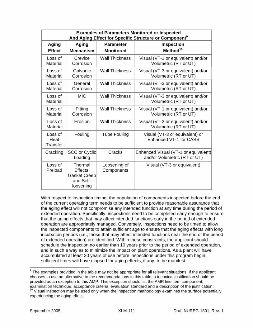
Examples of Parameters Monitored or Inspected And Aging Effect for Specific Structure or Component9
Aging Effect
Aging Mechanism
Parameter Monitored
Inspection Method10
Loss of Material
Crevice Corrosion
Wall Thickness Visual (VT-1 or equivalent) and/or Volumetric (RT or UT)
Loss of Material
Galvanic Corrosion
Wall Thickness Visual (VT-3 or equivalent) and/or Volumetric (RT or UT)
Loss of Material
General Corrosion
Wall Thickness Visual (VT-3 or equivalent) and/or Volumetric (RT or UT)
Loss of Material
MIC Wall Thickness Visual (VT-3 or equivalent) and/or Volumetric (RT or UT)
Loss of Material
Pitting Corrosion
Wall Thickness Visual (VT-1 or equivalent) and/or Volumetric (RT or UT)
Loss of Material
Erosion Wall Thickness Visual (VT-3 or equivalent) and/or Volumetric (RT or UT)
Loss of Heat
Transfer
Fouling Tube Fouling Visual (VT-3 or equivalent) or Enhanced VT-1 for CASS
Cracking SCC or Cyclic Loading
Cracks Enhanced Visual (VT-1 or equivalent) and/or Volumetric (RT or UT)
Loss of Preload
Thermal Effects,
Gasket Creep and Self-loosening
Loosening of Components
Visual (VT-3 or equivalent)
With respect to inspection timing, the population of components inspected before the end of the current operating term needs to be sufficient to provide reasonable assurance that the aging effect will not compromise any intended function at any time during the period of extended operation. Specifically, inspections need to be completed early enough to ensure that the aging effects that may affect intended functions early in the period of extended operation are appropriately managed. Conversely, inspections need to be timed to allow the inspected components to attain sufficient age to ensure that the aging effects with long incubation periods (i.e., those that may affect intended functions near the end of the period of extended operation) are identified. Within these constraints, the applicant should schedule the inspection no earlier than 10 years prior to the period of extended operation, and in such a way as to minimize the impact on plant operations. As a plant will have accumulated at least 30 years of use before inspections under this program begin, sufficient times will have elapsed for aging effects, if any, to be manifest.
9 The examples provided in the table may not be appropriate for all relevant situations. If the applicant chooses to use an alternative to the recommendations in this table, a technical justification should be provided as an exception to this AMP. This exception should list the AMR line item component, examination technique, acceptance criteria, evaluation standard and a description of the justification. 10 Visual inspection may be used only when the inspection methodology examines the surface potentially experiencing the aging effect.
September 2005 XI M-111 Draft NUREG-1801, Rev. 1
5. Monitoring and Trending: The program provides for increasing of the inspection sample size and locations in the event that aging effects are detected. Determination of the sample size is based on an assessment of materials of fabrication, environment, plausible aging effects, and operating experience. Unacceptable inspection findings are evaluated in accordance with the site corrective action process to determine the need for subsequent (including periodic) inspections and for monitoring and trending the results.
6. Acceptance Criteria: Any indication or relevant conditions of degradation detected are evaluated. For example, the ultrasonic thickness measurements are to be compared to predetermined limits, such as the design minimum wall thickness for piping.
7. Corrective Actions: Site quality assurance (QA) procedures, review and approval processes, and administrative controls are implemented in accordance with the requirements of 10 CFR Part 50, Appendix B. As discussed in the appendix to this report, the staff finds the requirements of 10 CFR Part 50, Appendix B, acceptable to address the corrective actions, confirmation process, and administrative controls.
8. Confirmation Process: See Item 7, above.
9. Administrative Controls: See Item 7, above.
10. Operating Experience: This program applies to potential aging effects for which there are currently no operating experience indicating the need for an aging management program. Nevertheless, the elements that comprise these inspections (e.g., the scope of the inspections and inspection techniques) are consistent with industry practice.
References
10 CFR Part 50, Appendix B, Quality Assurance Criteria for Nuclear Power Plants, Office of the Federal Register, National Archives and Records Administration, 2005.
10 CFR 50.55a, Codes and Standards, Office of the Federal Register, National Archives and Records Administration, 2005.
ASME Section XI, Rules for Inservice Inspection of Nuclear Power Plant Components, ASME Boiler and Pressure Vessel Code, 2001 edition including the 2002 and 2003 Addenda, American Society of Mechanical Engineers, New York, NY.
Draft NUREG-1801, Rev. 1 XI M-112 September 2005
XI.M33 SELECTIVE LEACHING OF MATERIALS
Program Description
The program for selective leaching of materials ensures the integrity of the components made of cast iron, bronze, brass, and other alloys exposed to a raw water, brackish water, treated water, or groundwater environment that may lead to selective leaching of one of the metal components. The aging management program (AMP) includes a one-time visual inspection and hardness measurement of selected components that may be susceptible to selective leaching to determine whether loss of materials due to selective leaching is occurring, and whether the process will affect the ability of the components to perform their intended function for the period of extended operation.
Evaluation and Technical Basis
1. Scope of Program: This AMP determines the acceptability of the components that may be susceptible to selective leaching and assesses their ability to perform the intended function during the period of extended operation. These components include piping, valve bodies and bonnets, pump casings, and heat exchanger components. The materials of construction for these components may include cast iron, brass, bronze, or aluminum-bronze. These components may be exposed to a raw water, treated water, or groundwater environment. The AMP includes a one-time visual inspection and hardness measurement of a selected set of sample components to determine whether loss of material due to selective leaching is not occurring for the period of extended operation.
The selective leaching process involves the preferential removal of one of the alloying elements from the material, which leads to the enrichment of the remaining alloying elements. Dezincification (loss of zinc from brass) and graphitization (removal of iron from cast iron) are examples of such a process. Susceptible materials, high temperatures, stagnant-flow conditions, and corrosive environment such as acidic solutions, for example, for brasses with high zinc content, and dissolved oxygen, are conducive to selective leaching.
2. Preventive Actions: The one-time visual inspection and hardness measurement is an inspection/verification program; thus, there is no preventive action. However, it is noted that monitoring of water chemistry to control pH and concentration of corrosive contaminants, and treatment with hydrazine to minimize dissolved oxygen in water are effective in reducing selective leaching.
3. Parameters Monitored/Inspected: The visual inspection and hardness measurement is to be a one-time inspection. Because selective leaching is a slow acting corrosion process, this measurement is performed just before the beginning of the license renewal period. Follow-up of unacceptable inspection findings includes expansion of the inspection sample size and location.
4. Detection of Aging Effects: The one-time visual inspection and hardness measurement includes close examination of a select set of components to determine whether selective leaching has occurred and whether the resulting loss of strength and/or material will affect the intended functions of these components during the period of extended operation. Selective leaching generally does not cause changes in dimensions and is difficult to detect. However, in certain brasses it causes plug-type dezincification, which can be
September 2005 XI M-113 Draft NUREG-1801, Rev. 1
detected by visual inspection. One acceptable procedure is to visually inspect the susceptible components closely and conduct Brinell Hardness testing on the inside surfaces of the selected set of components to determine if selective leaching has occurred. If it is occurring, an engineering evaluation is initiated to determine acceptability of the affected components for further service.
5. Monitoring and Trending: There is no monitoring and trending for the one-time visual inspection and hardness measurement.
6. Acceptance Criteria: Identification of selective leaching will define the need for further engineering evaluation before the affected components can be qualified for further service. If necessary, the evaluation will include a root cause analysis.
7. Corrective Actions: Evaluations are performed for test or inspection results that do not satisfy established acceptance criteria. The corrective actions program ensures that conditions adverse to quality are promptly corrected. If the deficiency is assessed to be significantly adverse to quality, the cause of the condition is determined and an action plan is developed to preclude repetition. As discussed in the appendix to this report, the staff finds the requirements of 10 CFR Part 50, Appendix B, acceptable to address the corrective actions.
8. Confirmation Process: Site quality assurance (QA) procedures, review and approval processes, and administrative controls are implemented in accordance with the requirements of 10 CFR Part 50, Appendix B. As discussed in the appendix to this report, the staff finds the requirements of 10 CFR Part 50, Appendix B, acceptable to address the confirmation process and administrative controls.
9. Administrative Controls: See Item 8, above.
10. Operating Experience: One-time inspection is a new program to be applied by the applicant. The elements that comprise these inspections (e.g., the scope of the inspections and inspection techniques) are consistent with industry practice and staff expectations.
References
10 CFR Part 50, Appendix B, Quality Assurance Criteria for Nuclear Power Plants, Office of the Federal Register, National Archives and Records Administration, 2005.
NRC Safety Evaluation Report Related to the License Renewal of Calvert Cliffs Nuclear Power Plant, Units 1 and 2, NUREG-1705, December 1999.
NRC Safety Evaluation Report Related to the License Renewal of Oconee Nuclear Station, Units 1, 2, and 3, NUREG-1723, March 2000.
Draft NUREG-1801, Rev. 1 XI M-114 September 2005
XI.M34 BURIED PIPING AND TANKS INSPECTION
Program Description
The program includes (a) preventive measures to mitigate corrosion, and (b) periodic inspection to manage the effects of corrosion on the pressure-retaining capacity of buried steel piping and tanks. Gray cast iron, which is included under the definition of steel, is also subject to a loss of material due to selective leaching, which is an aging effect managed under Chapter XI.M33, “Selective Leaching of Materials.”
Preventive measures are in accordance with standard industry practice for maintaining external coatings and wrappings. Buried piping and tanks are inspected when they are excavated during maintenance and when a pipe is dug up and inspected for any reason.
This program is an acceptable option to manage buried piping and tanks, except further evaluation is required for the program element/attributes of detection of aging effects (regarding inspection frequency) and operating experience.
Evaluation and Technical Basis
1. Scope of Program: The program relies on preventive measures such as coating, wrapping and periodic inspection for loss of material caused by corrosion of the external surface of buried steel piping and tanks. Loss of material in these components, which may be exposed to aggressive soil environment, is caused by general, pitting, and crevice corrosion, and microbiologically-influenced corrosion (MIC). Periodic inspections are performed when the components are excavated for maintenance or for any other reason. The scope of the program covers buried components that are within the scope of license renewal for the plant.
2. Preventive Actions: In accordance with industry practice, underground piping and tanks are coated during installation with a protective coating system, such as coal tar enamel with a fiberglass wrap and a kraft paper outer wrap, a polyolifin tape coating, or a fusion bonded epoxy coating to protect the piping from contacting the aggressive soil environment.
3. Parameters Monitored/Inspected: The program monitors parameters such as coating and wrapping integrity that are directly related to corrosion damage of the external surface of buried steel piping and tanks. Coatings and wrappings are inspected by visual techniques. Any evidence of damaged wrapping or coating defects, such as coating perforation, holidays, or other damage, is an indicator of possible corrosion damage to the external surface of piping and tanks.
4. Detection of Aging Effects: Inspections performed to confirm that coating and wrapping are intact are an effective method to ensure that corrosion of external surfaces has not occurred and the intended function is maintained. Buried piping and tanks are opportunistically inspected whenever they are excavated during maintenance. When opportunistic, the inspections are performed in areas with the highest likelihood of corrosion problems, and in areas with a history of corrosion problems, within the areas made accessible to support the maintenance activity.
September 2005 XI M-115 Draft NUREG-1801, Rev. 1
The applicant’s program is to be evaluated for the extended period of operation. It is anticipated that one or more opportunistic inspections may occur within a ten-year period. Prior to entering the period of extended operation, the applicant is to verify that there is at least one opportunistic or focused inspection is performed within the past ten years. Upon entering the period of extended operation, the applicant is to perform a focused inspection within ten years, unless an opportunistic inspection occurred within this ten-year period. Any credited inspection should be performed in areas with the highest likelihood of corrosion problems, and in areas with a history of corrosion problems.
5. Monitoring and Trending: Results of previous inspections are used to identify susceptible locations.
6. Acceptance Criteria: Any coating and wrapping degradations are reported and evaluated according to site corrective actions procedures.
7. Corrective Actions: The site corrective actions program, quality assurance (QA) procedures, site review and approval process, and administrative controls are implemented in accordance with the requirements of 10 CFR Part 50, Appendix B. The staff finds the requirements of 10 CFR Part 50, Appendix B, acceptable to address the corrective actions, confirmation process, and administrative controls.
8. Confirmation Process: See Item 7, above.
9. Administrative Controls: See Item 7, above.
10. Operating Experience: Operating experience shows that the program described here is effective in managing corrosion of external surfaces of buried steel piping and tanks. However, because the inspection frequency is plant-specific and depends on the plant operating experience, the applicant’s plant-specific operating experience is further evaluated for the extended period of operation.
References
10 CFR Part 50, Appendix B, Quality Assurance Criteria for Nuclear Power Plants, Office of the Federal Register, National Archives and Records Administration, 2005.
Draft NUREG-1801, Rev. 1 XI M-116 September 2005
XI.M35 ONE-TIME INSPECTION OF ASME CODE CLASS 1 SMALL-BORE PIPING
Program Description
This program is applicable to small-bore ASME Code Class 1 piping and systems less than -or equal to 4 inches nominal pipe size (NPS 4), which includes pipes, fittings, and branch connections. According to Table IWB-2500-1, Examination Category B-J Item No. B9.21 of the current ASME code, for small-bore Class 1 piping, a surface examination should be included for piping less than or equal to NPS 4 and greater than or equal to NPS 1. Also, Examination Category B-P requires system leakage and hydrostatic tests. However, the staff believes that, for a one-time inspection to detect cracking resulting from thermal and mechanical loading or intergranular stress corrosion, the inspection should be a volumetric examination. This is to provide additional assurance that either aging of small-bore ASME Code Class 1 piping is not occurring or the aging is insignificant, such that an aging management program (AMP) is not warranted. This program is applicable only to plants that have not experienced cracking of ASME Code Class 1 small-bore piping resulting from stress corrosion or thermal and mechanical loading. Should evidence of significant aging be revealed by a one-time inspection or previous operating experience, periodic inspection will be proposed, as managed by a plant-specific AMP.
Evaluation and Technical Basis
1. Scope of Program: This program is a one-time inspection of a sample of ASME Code Class 1 piping less than or equal to NPS 4. The program includes measures to verify that degradation is not occurring; thereby either confirming that there is no need to manage aging-related degradation or validate the effectiveness of any existing AMP for the period of extended operation. The one-time inspection program for ASME Code Class 1 small-bore piping includes locations that are susceptible to cracking. Guidelines for identifying piping susceptible to potential effects of thermal stratification or turbulent penetration are provided in EPRI Report 1000701, "Interim Thermal Fatigue Management Guideline (MRP-24)," January 2001.
2. Preventive Actions: This program is an inspection activity independent of methods to mitigate or prevent degradation.
3. Parameters Monitored/Inspected: This inspection detects cracking in ASME Code Class 1 small-bore piping.
4. Detection of Aging Effects: The inspection is designed to provide assurance, in plants that have not experienced cracking of ASME Code Class 1 small-bore piping due to stress corrosion or thermal and mechanical loading, that aging of this piping is not occurring or that the effects of aging are not significant. For ASME Code Class 1small-bore piping, one-time inspections using volumetric examination are performed on selected weld locations to detect cracking.
5. Monitoring and Trending: This is a one-time inspection to determine whether cracking in ASME Code Class 1 small-bore piping resulting from stress corrosion or thermal and mechanical loading is an issue. A one-time volumetric inspection is an acceptable method for confirming that cracking of ASME Code Class 1 small-bore piping, as a result of stress corrosion or thermal and mechanical loading, is not occurring in plants that have not experienced cracking due to these aging effects. However, evaluation of the inspection
September 2005 XI M-117 Draft NUREG-1801, Rev. 1
results may indicate the need for additional examinations, i.e., a plant-specific AMP, consistent with ASME Section XI, Subsection IWB. This inspection should be performed at a sufficient number of locations to assure an adequate sample. This number, or sample size, will be based on susceptibility, inspectability, dose considerations, operating experience, and limiting locations of the total population of ASME Code Class 1 small-bore piping locations.
6. Acceptance Criteria: If flaws or indications exceed the acceptance criteria of ASME Code, Section XI, Paragraph IWB-3400, they will be evaluated in accordance with ASME Code, Section XI, Paragraph IWB-3131, and additional examinations are performed in accordance with ASME Code, Section XI, Paragraph IWB-2430.
7. Corrective Actions: The site corrective action program, quality assurance (QA) procedures, site review and approval process, and administrative controls are implemented in accordance with the requirements of 10 CFR Part 50, Appendix B. As discussed in the appendix to this report, the staff finds the requirements of 10 CFR Part 50, Appendix B, acceptable to address the corrective actions, confirmation process, and administrative controls.
8. Confirmation Process: See Item 7, above.
9. Administrative Controls: See Item 7 above.
10. Operating Experience: This inspection uses volumetric inspection techniques with demonstrated capability and a proven industry record to detect cracking in piping weld and base material. However, the application of the specific technique to ASME Code Class 1 small-bore piping needs to be qualified before the examination.
References
10 CFR Part 50, Appendix B, Quality Assurance Criteria for Nuclear Power Plants, Office of the Federal Register, National Archives and Records Administration, 2005.
10 CFR 50.55a, Codes and Standards, Office of the Federal Register, National Archives and Records Administration, 2005.
ASME Section XI, Rules for Inservice Inspection of Nuclear Power Plant Components, ASME Boiler and Pressure Vessel Code, 2001 edition including the 2002 and 2003 Addenda, American Society of Mechanical Engineers, New York, NY.
NRC Information Notice 97-46, Unisolable Crack in High-Pressure Injection Piping, U.S. Nuclear Regulatory Commission, July 9, 1997.
EPRI Report 1000701, “Interim Thermal Fatigue Management Guideline (MRP-24),” January 2001 (ADAMS Accession No. ML010810162).
Draft NUREG-1801, Rev. 1 XI M-118 September 2005
XI.M36 EXTERNAL SURFACES MONITORING
Program Description
The External Surfaces Monitoring program is based on system inspections and walkdowns. This program consists of periodic visual inspections of steel components such as piping, piping components, ducting, and other components within the scope of license renewal and subject to AMR in order to manage aging effects. The program manages aging effects through visual inspection of external surfaces for evidence of material loss. Loss of material due to boric acid corrosion is managed by the Boric Acid Corrosion Program.
Evaluation and Technical Basis
1. Scope of Program: This program visually inspects the external surface of in-scope components and monitors external surfaces of steel components in systems within the scope of license renewal and subject to AMR for loss of material and leakage. Visual inspections are expected to identify loss of material due to general corrosion in accessible steel components. Loss of material due to pitting and crevice corrosion may not be detectable through these same visual inspections, however, general corrosion is expected to be present and detectable such that, should pitting and crevice corrosion exist, general corrosion will manifest itself as visible rust or rust byproducts (e.g., discoloration or coating degradation) and be detectable prior to any loss of intended function. Therefore, this program is acceptable for use in inspecting for loss of material for general, pitting and crevice corrosion.
Surfaces that are inaccessible or not readily visible during plant operations are inspected during refueling outages. Surfaces that are inaccessible or not readily visible during both plant operations and refueling outages are inspected at such intervals that would provide reasonable assurance that the effects of aging will be managed such that applicable components will perform their intended function during the period of extended operation.
Surfaces that are insulated may be inspected when the external surface is exposed (i.e., maintenance) at such intervals that would provide reasonable assurance that the effects of aging will be managed such that applicable components will perform their intended function during the period of extended operation.
The program may also be credited with managing loss of material from internal surfaces, for situations in which material and environment combinations are the same for internal and external surfaces such that external surface condition is representative of internal surface condition. When credited, the program should describe the component internal environment and the credited similar external component environment inspected.
2. Preventive Actions: The External Surfaces Monitoring Program is a visual monitoring program that does not include preventive actions.
September 2005 XI M-119 Draft NUREG-1801, Rev. 1
3. Parameters Monitored/Inspected: The External Surfaces Monitoring Program utilizes periodic plant system inspections and walkdowns to monitor for material degradation and leakage. This program inspects components such as piping, piping components, ducting and other components. Coatings deterioration is an indicator of possible underlying degradation.
Examples of inspection parameters include:
• corrosion and material wastage (loss of material); • leakage from or onto external surfaces; • worn, flaking, or oxide-coated surfaces; • corrosion stains on thermal insulation; • protective coating degradation (cracking and flaking)
4. Detection of Aging Effects: Degradation of steel surfaces cannot occur without the degradation of the paint or coating. Confirmation of the integrity of the paint or coating is an effective method for managing the effects of corrosion on the steel surface. A visual inspection is conducted for component surfaces at least once per refueling cycle. This frequency accommodates inspections of components that may be in locations that are normally only accessible during outages. System walkdowns are normally performed on a frequency that exceeds once per fuel cycle. Surfaces that are inaccessible or not readily visible during plant operations and refueling outages are inspected at such intervals that would ensure the components intended function is maintained. The intervals of inspections may be adjusted as necessary based on plant-specific inspection results and industry experience.
This program is credited with managing the following aging effects.
• loss of material for external surfaces; • loss of material for internal surfaces exposed to the same environment as the external
surface
5. Monitoring and Trending: Visual inspection activities are performed and associated personnel are qualified in accordance with site controlled procedures and processes. The External Surfaces Monitoring Program uses standardized monitoring and trending activities to track degradation. Deficiencies are documented using approved processes and procedures such that results can be trended. However, the program does not include formal trending. Inspections are performed at frequencies identified in Detection of Aging Effects.
6. Acceptance Criteria: For each component/aging effect combination, the acceptance criteria are defined to ensure that the need for corrective actions will be identified before loss of intended functions. Acceptance criteria include design standards, procedural requirements, current licensing basis, industry codes or standards, and engineering evaluation.
7. Corrective Actions: Site quality assurance (QA) procedures, review and approval processes, and administrative controls are implemented in accordance with the requirements of 10 CFR Part 50, Appendix B. As discussed in the appendix to this report, the staff finds the requirements of 10 CFR Part 50, Appendix B, acceptable to address the corrective actions, confirmation process, and administrative controls.
Draft NUREG-1801, Rev. 1 XI M-120 September 2005
8. Confirmation Process: See Item 7, above.
9. Administrative Controls: See Item 7, above.
10. Operating Experience: External surfaces inspections via system inspections and walkdowns have been in effect at many utilities since the mid 1990's in support of the Maintenance Rule (10 CFR 50.65) and have proven effective in maintaining the material condition of plant systems. The elements that comprise these inspections (e.g., the scope of the inspections and inspection techniques) are consistent with industry practice.
References
10 CFR Part 50, Appendix B, Quality Assurance Criteria for Nuclear Power Plants, Office of the Federal Register, National Archives and Records Administration, 2005.
INPO Good Practice TS-413, Use of System Engineers, INPO 85-033, May 18, 1988.
EPRI Technical Report 1007933 "Aging Assessment Field Guide," December 2003
EPRI Technical Report 1009743 "Aging Identification and Assessment Checklist," August 27, 2004.
September 2005 XI M-121 Draft NUREG-1801, Rev. 1
XI.M37 FLUX THIMBLE TUBE INSPECTION
Program Description
The Flux Thimble Tube Inspection is an inspection program used to monitor for thinning of the flux thimble tube wall, which provides a path for the incore neutron flux monitoring system detectors and forms part of the RCS pressure boundary. Flux thimble tubes are subject to loss of material at certain locations in the reactor vessel where flow-induced fretting causes wear at discontinuities in the path from the reactor vessel instrument nozzle to the fuel assembly instrument guide tube. An NDE methodology, such as eddy current testing (ECT), is used to monitor for wear of the flux thimble tubes. This program implements the recommendations of NRC Bulletin 88-09, “Thimble Tube Thinning in Westinghouse Reactors,” as described below.
Evaluation and Technical Basis
1. Scope of Program: The flux thimble tube Inspection encompasses all of the flux thimble tubes that form part of the reactor coolant system pressure boundary. The flux thimble guide tubes are not in the scope of this program. Within scope are the licensee responses to Bulletin 88-09, as accepted by the staff in its closure letters on the Bulletin, and any amendments to the licensee responses as approved by the staff.
2. Preventive Actions: The program consists of inspection and evaluation and provides no guidance on preventive actions.
3. Parameters Monitored/Inspected: Flux thimble tube wall thickness will be monitored to detect loss of material from the flux thimble tubes during the period of extended operation.
4. Detection of Aging Effects: An inspection methodology (such as ECT) that has been demonstrated to be capable of adequately detecting wear of the flux thimble tubes will be employed to detect loss of material during the period of extended operation. Justification for methods other than ECT should be provided unless use of the alternative method has been previously accepted by the Nuclear Regulatory Commission (NRC). The inspection results will be evaluated and compared with the acceptance criteria established as discussed in element 6 below.
5. Monitoring and Trending: The wall thickness measurements will be trended and wear rates will be calculated. Examination frequency will be based upon wear predictions that have been technically justified as providing conservative estimates of flux thimble tube wear. The interval between inspections will be established such that no flux thimble tube is predicted to incur wear that exceeds the established acceptance criteria before the next inspection. The examination frequency may be adjusted based on plant-specific wear projections. Re-baselining of the examination frequency should be justified using plant-specific wear-rate data unless prior plant-specific NRC acceptance for the re-baselining was received. If design changes are made to use more wear-resistant thimble tube materials (e.g., chrome-plated stainless steel) sufficient inspections will be conducted at an adequate inspection frequency, as described above, for the new materials.
6. Acceptance Criteria: Appropriate acceptance criteria such as percent through-wall wear will be established. The acceptance criteria will be technically justified to provide an adequate margin of safety to ensure that the integrity of the reactor coolant system pressure boundary is maintained. The acceptance criteria will include allowances for
Draft NUREG-1801, Rev. 1 XI M-122 September 2005
factors such as instrument uncertainty, uncertainties in wear scar geometry, and other potential inaccuracies, as applicable, to the inspection methodology chosen for use in the program. Acceptance criteria different from those previously documented in NRC acceptance letters for the applicant’s response to Bulletin 88-09 and amendments thereto should be justified.
7. Corrective Actions: Flux thimble tube wall thickness which do not meet the established acceptance criteria must be isolated, capped, plugged, withdrawn, replaced, or otherwise removed from service in a manner that ensures the integrity of the reactor coolant system pressure boundary is maintained. Analyses may allow repositioning of flux thimble tubes that are approaching the acceptance criteria limit. Repositioning of a tube exposes a different portion of the tube to the discontinuity that is causing the wear.
Flux thimble tubes that cannot be inspected over the tube length, that is subject to wear due to restriction or other defect, and that can not be shown by analysis to be satisfactory for continued service, must be removed from service to ensure the integrity of the reactor coolant system pressure boundary.
The site corrective actions program, quality assurance (QA) procedures, site review and approval process, and administrative controls are implemented in accordance with 10 CFR Part 50, Appendix B. As discussed in the appendix to this report, the staff finds the requirements of 10 CFR Part 50, Appendix B, acceptable to address the corrective actions, confirmation process, and administrative controls.
8. Confirmation Process: See Item 7, above.
9. Administrative Controls: See Item 7, above.
10. Operating Experience: In IE Bulletin 88-09, “Thimble Tube Thinning in Westinghouse Reactors,” the NRC requested that licensees implement a flux thimble tube inspection program due to several instances of leaks, and due to licensees identifying wear. Utilities established inspection programs in accordance with IE Bulletin 88-09 which have shown excellent results in identifying and managing wear of flux thimble tubes.
As discussed in IE Bulletin 88-09, the amount of vibration the thimble tubes experience is determined by many plant-specific factors. Therefore, the only effective method for determining thimble tube integrity is through inspections which are adjusted to account for plant-specific wear patterns and history.
References
10 CFR Part 50, Appendix B, Quality Assurance Criteria for Nuclear Power Plants, Office of the Federal Register, National Archives and Records Administration, 2005.
NRC Bulletin 88-09, “Thimble Tube Thinning in Westinghouse Reactors,” July 26, 1988.
NRC Information Notice No. 87-44, Supplement 1, "Thimble Tube Thinning in Westinghouse Reactors," March 28, 1988.
NRC Information Notice No. 87-44, "Thimble Tube Thinning in Westinghouse Reactors," September 16, 1987.
September 2005 XI M-123 Draft NUREG-1801, Rev. 1
XI.M38 INSPECTION OF INTERNAL SURFACES IN MISCELLANEOUS PIPING AND DUCTING COMPONENTS
Program Description
The program consists of inspections of the internal surfaces of steel piping, piping components, ducting, and other components that are not covered by other aging management programs. These internal inspections are performed during the periodic system and component surveillances or during the performance of maintenance activities when the surfaces are made visible. The program includes visual inspections to assure that existing environmental conditions are not causing material degradation that could result in a loss of component intended functions. If visual inspection of internal surfaces is not possible, then the applicant needs to provide a plant-specific program.
Evaluation and Technical Basis
1. Scope of Program: The program visual inspections include internal surfaces of steel piping, piping elements, ducting, and components in an internal environment (such as indoor uncontrolled air, condensation, and steam) that are not included in other aging management programs for loss of material. Inspections are performed when the internal surfaces are accessible during the performance of periodic surveillances, during maintenance activities or during scheduled outages. This program includes indication of borated water leakage on internal surfaces.
2. Preventive Actions: This program is an inspection activity independent of methods to mitigate or prevent degradation.
3. Parameters Monitored/Inspected: Visual inspections of internal surfaces of plant components are performed during maintenance or surveillance activities. Parameters monitored or inspected include visible evidence of corrosion to indicate possible loss of materials.
4. Detection of Aging Effects: Periodic inspections provide for detection of aging effects prior to the loss of component function. For painted or coated surfaces, degradation of steel surfaces cannot occur without the degradation of the paint or coating. Confirmation of the integrity of the paint or coating is an effective method for managing the effects of corrosion on the steel surface. The applicant should identify and justify the inspection technique used for detecting the aging effects of concern. Locations should be chosen to include conditions likely to exhibit these aging effects. Inspection intervals are established such that they provide timely detection of degradation.
5. Monitoring and Trending: Visual inspection activities are performed and associated personnel are qualified in accordance with site controlled procedures and processes. Maintenance and surveillance activities provide for monitoring and trending of aging degradation. Inspection intervals are dependent on component material and environment, and take into consideration industry and plant-specific operating experience. Results of the periodic inspections are monitored for indications of various corrosion mechanisms and fouling. The extent and schedule of inspections and testing assure detection of component degradation prior to loss of intended functions.
Draft NUREG-1801, Rev. 1 XI M-124 September 2005
6. Acceptance Criteria: Indications of various corrosion mechanisms or fouling that would impact component intended function are reported and will require further evaluation. The acceptance criteria are established in the maintenance and surveillance procedures or other established plant procedures. If the results are not acceptable, the corrective action program is implemented to assess the material condition and determine whether the component intended function is affected.
7. Corrective Actions: Site corrective actions program, quality assurance (QA) procedures, site review and approval process, and administrative controls are implemented in accordance with the requirements of 10 CFR Part 50, Appendix B. As discussed in the appendix to this report, the staff finds the requirements of 10 CFR Part 50, Appendix B, acceptable to address the corrective actions, confirmation process, and administrative controls.
8. Confirmation Process: See item 7, above.
9. Administrative Controls: See item 7, above.
10. Operating Experience: Inspection of internal surfaces during the performance of periodic surveillances and maintenance activities have been in effect at many utilities in support of plant components reliability programs. These activities have proven effective in maintaining the material condition of plant systems, structures, and components.
The elements that comprise these inspections (e.g., the scope of the inspections and inspection techniques) are consistent with industry practice and staff expectations. However, because the inspection frequency is plant-specific and depends on the plant operating experience, the applicant’s plant-specific operating experience or applicable generic operating experience is further evaluated for the extended period of operation. The applicant is to evaluate recent operating experience and provide objective evidence to support the conclusion that the effects of aging are adequately managed.
References
10 CFR Part 50, Appendix B, Quality Assurance Criteria for Nuclear Power Plants, Office of the Federal Register, National Archives and Records Administration, 2005.
EPRI Technical Report 1007933 "Aging Assessment Field Guide," December 2003
September 2005 XI M-125 Draft NUREG-1801, Rev. 1
XI.M39LUBRICATING OIL ANALYSIS PROGRAM
Program Description
The purpose of the Lubricating Oil Analysis Program is to ensure the oil environment in the mechanical systems is maintained to the required quality. The Lubricating Oil Analysis Program maintains oil systems contaminants (primarily water and particulates) within acceptable limits, thereby preserving an environment that is not conducive to loss of material, cracking or reduction of heat transfer. Lubricating oil testing activities include sampling and analysis of lubricating oil for detrimental contaminants. The presence of water or particulates may also be indicative of inleakage and corrosion product buildup.
Evaluation and Technical Basis
1. Scope of Program: On a periodic basis, this program samples lubricating oil from plant components subject to aging management review.
2. Preventive Actions: The lubricating oil analysis program maintains oil systems contaminants (primarily water and particulates) within acceptable limits.
3. Parameters Monitored/Inspected: For components with periodic oil changes in accordance with manufacturer’s recommendations, a particle count and check for water are performed to detect evidence of abnormal wear rates, contamination by moisture, or excessive corrosion. For components that do not have regular oil changes, viscosity, neutralization number, and flash point are also determined to verify the oil is suitable for continued use. In addition, analytical ferrography and elemental analysis are performed to identify wear particles.
4. Detection of Aging Effects: Periodic sampling and compliance with the acceptance criteria provide assurance that lube oil contaminants do not exceed acceptable levels, thereby preserving an environment that is not conducive to aging mechanisms that could lead to the aging effects of loss of material, cracking and reduction of heat transfer.
5. Monitoring and Trending: Oil analysis results are reviewed to determine if alert levels or limits have been reached or exceeded. This review also checks for unusual trends.
6. Acceptance Criteria: Particle concentration will be determined in accordance with industry standards such as SAE749D, ISO 4406, ISO 112218, and NAS 1638. Water and particle concentration will not exceed limits based on manufacturer’s recommendations or industry standards recommended for each components type. Viscosity bands are based on a tolerance around the base viscosity of the lubricating oil as recommended by the components manufacturer or industry standards. Metal limits as determined by spectral analysis and ferrography will be based on original baseline data and manufacturer’s recommendations, industry standards, or other justified basis.
7. Corrective Actions: Pursuant to 10 CFR Part 50, Appendix B, specific corrective actions are implemented in accordance with the plant quality assurance (QA) program. For example, if a limit is reached or exceeded, actions to address the condition are taken. These may include increased monitoring, vibration analysis, corrective maintenance, further laboratory analysis, and engineering evaluation. As discussed in the appendix to
Draft NUREG-1801, Rev. 1 XI M-126 September 2005
this report, the staff finds the requirements of 10 CFR Part 50, Appendix B, acceptable to address the corrective actions.
8. Confirmation Process: Site QA procedures, review and approval processes, and administrative controls are implemented in accordance with the requirements of 10 CFR Part 50, Appendix B. As discussed in the appendix to this report, the staff finds the requirements of 10 CFR Part 50, Appendix B, acceptable to address the confirmation process and administrative controls.
9. Administrative Controls: See item 8, above.
10. Operating Experience: The operating experience at some plants has identified water in the lubricating oil, and particulate contamination. However, no instances of component failures attributed to lubricating oil contamination have been identified.
References
10 CFR Part 50, Appendix B, Quality Assurance Criteria for Nuclear Power Plants, Office of the Federal Register, National Archives and Records Administration, 2005.
September 2005 XI M-127 Draft NUREG-1801, Rev. 1
XI.S1 ASME SECTION XI, SUBSECTION IWE
Program Description
10 CFR 50.55a imposes the inservice inspection (ISI) requirements of the American Society of Mechanical Engineers (ASME) Boiler and Pressure Vessel (B&PV) Code, Section XI, Subsection IWE for steel containments (Class MC) and steel liners for concrete containments (Class CC). The full scope of IWE includes steel containment shells and their integral attachments; steel liners for concrete containments and their integral attachments; containment hatches and airlocks; seals, gaskets and moisture barriers; and pressure-retaining bolting. This evaluation covers the 2001 edition1 including the 2002 and 2003 Addenda, as approved in 10 CFR 50.55a. ASME Code Section XI, Subsection IWE and the additional requirements specified in 10 CFR 50.55a(b)(2) constitute an existing mandated program applicable to managing aging of steel containments, steel liners of concrete containments, and other containment components for license renewal.
The primary ISI method specified in IWE is visual examination (general visual, VT-3, VT-1). Limited volumetric examination (ultrasonic thickness measurement) and surface examination (e.g., liquid penetrant) may also be necessary in some instances. Bolt preload is checked by either a torque or tension test. IWE specifies acceptance criteria, corrective actions, and expansion of the inspection scope when degradation exceeding the acceptance criteria is found.
The evaluation of 10 CFR 50.55a and Subsection IWE as an aging management program (AMP) for license renewal is provided below.
Evaluation and Technical Basis
1. Scope of Program: Subsection IWE-1000 specifies the components of steel containments and steel liners of concrete containments within its scope. The components within the scope of Subsection IWE are Class MC pressure-retaining components (steel containments) and their integral attachments; metallic shell and penetration liners of Class CC containments and their integral attachments; containment seals and gaskets; containment pressure-retaining bolting; and metal containment surface areas, including welds and base metal. The concrete portions of containments are inspected in accordance with Subsection IWL.
Subsection IWE exempts the following from examination:
(1) Components that are outside the boundaries of the containment as defined in the plant-specific design specification;
(2) Embedded or inaccessible portions of containment components that met the requirements of the original construction code of record;
(3) Components that become embedded or inaccessible as a result of vessel repair or replacement, provided IWE-1232 and IWE-5220 are met; and
(4) Piping, pumps, and valves that are part of the containment system or that penetrate or are attached to the containment vessel (governed by IWB or IWC).
1 An applicant may rely on a different version of the ASME Code, but should justify such use. An applicant may wish to refer to the SOC for an update of 10 C.F.R. § 50.55a to justify use of a more recent edition of the Code.
September 2005 XI.S-1 Draft NUREG-1801, Rev. 1

10 CFR 50.55a(b)(2)(ix) specifies additional requirements for inaccessible areas. It states that the licensee is to evaluate the acceptability of inaccessible areas when conditions exist in accessible areas that could indicate the presence of or result in degradation to such inaccessible areas. Examination requirements for containment supports are not within the scope of Subsection IWE.
2. Preventive Action: No preventive actions are specified; Subsection IWE is a monitoring program.
3. Parameters Monitored or Inspected: Table IWE-2500-1 specifies seven categories for examination. The categories, parts examined, and examination methods are presented in the following table. The first six examination categories (E-A through E-G) constitute the ISI requirements of IWE. Examination category E-P references 10 CFR Part 50, Appendix J leak rate testing. Appendix J leak rate testing is evaluated as a separate AMP for license renewal in XI.S4.
CATEGORY PARTS EXAMINED EXAMINATION METHODa
E-A Containment surfaces General visual, visual VT-3 E-Bb Pressure retaining welds Visual VT-1 E-C Containment surfaces requiring
augmented examination Visual VT-1, volumetric
E-D Seals, gaskets, and moisture barriers Visual VT-3 E-Fb Pressure retaining dissimilar metal welds Surface E-G Pressure retaining bolting Visual VT-1, bolt torque or
tension test E-P All pressure-retaining components
(pressure retaining boundary, penetration bellows, airlocks, seals, and gaskets)
10 CFR Part 50, Appendix J (containment leak rate testing)
a
b
The applicable examination method (where multiple methods are listed) depends on the particular subcategory within each category.
These two categories are optional, in accordance with 10 CFR 50.55a(b)(2)(ix)(C).
Table IWE-2500-1 references the applicable section in IWE-3500 that identifies the aging effects that are evaluated. The parameters monitored or inspected depend on the particular examination category. For Examination Category E-A, as an example, metallic surfaces (without coatings) are examined for evidence of cracking, discoloration, wear, pitting, excessive corrosion, arc strikes, gouges, surface discontinuities, dents, and other signs of surface irregularities. For Examination Category E-D, seals, gaskets, and moisture barriers are examined for wear, damage, erosion, tear, surface cracks, or other defects that may violate the leak-tight integrity.
4. Detection of Aging Effects: The frequency and scope of examination specified in 10 CFR 50.55a and Subsection IWE ensure that aging effects would be detected before they would compromise the design-basis requirements. As indicated in IWE-2400, inservice examinations and pressure tests are performed in accordance with one of two inspection programs, A or B, on a specified schedule. Under Inspection Program A, there
Draft NUREG-1801, Rev. 1 XI S-2 September 2005
are four inspection intervals (at 3, 10, 23, and 40 years) for which 100% of the required examinations must be completed. Within each interval, there are various inspection periods for which a certain percentage of the examinations are to be performed to reach 100% at the end of that interval. In addition, a general visual examination is performed once each inspection period. After 40 years of operation, any future examinations will be performed in accordance with Inspection Program B. Under Inspection Program B, starting with the time the plant is placed into service, there is an initial inspection interval of 10 years and successive inspection intervals of 10 years each, during which 100% of the required examinations are to be completed. An expedited examination of containment is required by 10 CFR 50.55a in which an inservice (baseline) examination specified for the first period of the first inspection interval for containment is to be performed by September 9, 2001. Thereafter, subsequent examinations are performed every 10 years from the baseline examination. Regarding the extent of examination, all accessible surfaces receive a visual examination such as General Visual, VT-1, or VT-3 (see table in item 3 above). IWE-1240 requires augmented examinations (Examination Category E-C) of containment surface areas subject to degradation. A VT-1 visual examination is performed for areas accessible from both sides, and volumetric (ultrasonic thickness measurement) examination is performed for areas accessible from only one side.
5. Monitoring and Trending: With the exception of inaccessible areas, all surfaces are monitored by virtue of the examination requirements on a scheduled basis. When component examination results require evaluation of flaws, evaluation of areas of degradation, or repairs, and the component is found to be acceptable for continued service, the areas containing such flaws, degradation, or repairs shall be reexamined during the next inspection period, in accordance with Examination Category E-C. When these reexaminations reveal that the flaws, areas of degradation, or repairs remain essentially unchanged for three consecutive inspection periods, these areas no longer require augmented examination in accordance with Examination Category E-C.
IWE-2430 specifies that (a) examinations performed during any one inspection that reveal flaws or areas of degradation exceeding the acceptance standards are to be extended to include an additional number of examinations within the same category approximately equal to the initial number of examinations, and (b) when additional flaws or areas of degradation that exceed the acceptance standards are revealed, all of the remaining examinations within the same category are to be performed to the extent specified in Table IWE-2500-1 for the inspection interval. Alternatives to these examinations are provided in 10 CFR 50.55a(b)(2)(ix)(D).
6. Acceptance Criteria: IWE-3000 provides acceptance standards for components of steel containments and liners of concrete containments. Table IWE-3410-1 presents criteria to evaluate the acceptability of the containment components for service following the preservice examination and each inservice examination. This table specifies the acceptance standard for each examination category. Most of the acceptance standards rely on visual examinations. Areas that are suspect require an engineering evaluation or require correction by repair or replacement. For some examinations, such as augmented examinations, numerical values are specified for the acceptance standards. For the containment steel shell or liner, material loss exceeding 10% of the nominal containment wall thickness, or material loss that is projected to exceed 10% of the nominal containment wall thickness before the next examination, are documented. Such areas are to be accepted by engineering evaluation or corrected by repair or replacement in accordance with IWE-3122.
September 2005 XI.S-3 Draft NUREG-1801, Rev. 1
7. Corrective Actions: Subsection IWE states that components whose examination results indicate flaws or areas of degradation that do not meet the acceptance standards listed in Table-3410-1 are acceptable if an engineering evaluation indicates that the flaw or area of degradation is nonstructural in nature or has no effect on the structural integrity of the containment. Except as permitted by 10 CFR 50.55a(b)(ix)(D), components that do not meet the acceptance standards are subject to additional examination requirements, and the components are repaired or replaced to the extent necessary to meet the acceptance standards of IWE-3000. For repair of components within the scope of Subsection IWE, IWE-3124 states that repairs and reexaminations are to comply with IWA-4000. IWA-4000 provides repair specifications for pressure retaining components including metal containments and metallic liners of concrete containments. As discussed in the appendix to this report, the staff finds the requirements of 10 CFR Part 50, Appendix B, acceptable to address the corrective actions.
8. Confirmation Process: When areas of degradation are identified, an evaluation is performed to determine whether repair or replacement is necessary. If the evaluation determines that repair or replacement is necessary, Subsection IWE specifies confirmation that appropriate corrective actions have been completed and are effective. Subsection IWE states that repairs and reexaminations are to comply with the requirements of IWA-4000. Reexaminations are conducted in accordance with the requirements of IWA-2200, and the recorded results are to demonstrate that the repair meets the acceptance standards set forth in Table IWE-3410-1. As discussed in the appendix to this report, the staff finds the requirements of 10 CFR Part 50, Appendix B, acceptable to address the confirmation process.
9. Administrative Controls: IWA-6000 provides specifications for the preparation, submittal, and retention of records and reports. As discussed in the appendix to this report, the staff finds the requirements of 10 CFR Part 50, Appendix B, acceptable to address administrative controls.
10. Operating Experience: ASME Section XI, Subsection IWE was incorporated into 10 CFR 50.55a in 1996. Prior to this time, operating experience pertaining to degradation of steel components of containment was gained through the inspections required by 10 CFR Part 50, Appendix J and ad hoc inspections conducted by licensees and the Nuclear Regulatory Commission (NRC). NRC Information Notice (INs) 86-99, 88-82 and 89-79 described occurrences of corrosion in steel containment shells. NRC Generic Letter (GL) 87-05 addressed the potential for corrosion of boiling water reactor (BWR) Mark I steel drywells in the “sand pocket region.” More recently, NRC IN 97-10 identified specific locations where concrete containments are susceptible to liner plate corrosion. The program is to consider the liner plate and containment shell corrosion concerns described in these generic communications. Implementation of the ISI requirements of Subsection IWE, in accordance with 10 CFR 50.55a, is a necessary element of aging management for steel components of steel and concrete containments through the period of extended operation.
References
10 CFR Part 50, Appendix J, Primary Reactor Containment Leakage Testing for Water-Cooled Power Reactors, Office of the Federal Register, National Archives and Records Administration, 2000.
Draft NUREG-1801, Rev. 1 XI S-4 September 2005
10 CFR 50.55a, Codes and Standards, Office of the Federal Register, National Archives and Records Administration, 2005.
ASME Section XI, Rules for Inservice Inspection of Nuclear Power Plant Components, Subsection IWA, General Requirements, 2001 edition including the 2002 and 2003 Addenda, The ASME Boiler and Pressure Vessel Code, The American Society of Mechanical Engineers, New York, NY.
ASME Section XI, Rules for Inservice Inspection of Nuclear Power Plant Components, Subsection IWB, Requirements for Class 1 Components of Light-Water Cooled Power Plants, 2001 edition including the 2002 and 2003 Addenda , The ASME Boiler and Pressure Vessel Code, The American Society of Mechanical Engineers, New York, NY.
ASME Section XI, Rules for Inservice Inspection of Nuclear Power Plant Components, Subsection IWC, Requirements for Class 2 Components of Light-Water Cooled Power Plants, 2001 edition including the 2002 and 2003 Addenda, The ASME Boiler and Pressure Vessel Code, The American Society of Mechanical Engineers, New York, NY.
ASME Section XI, Rules for Inservice Inspection of Nuclear Power Plant Components, Subsection IWE, Requirements for Class MC and Metallic Liners of Class CC Components of Light-Water Cooled Power Plants, 2001 edition including the 2002 and 2003 Addenda, The ASME Boiler and Pressure Vessel Code, The American Society of Mechanical Engineers, New York, NY.
ASME Section XI, Rules for Inservice Inspection of Nuclear Power Plant Components, Subsection IWL, Requirements for Class CC Concrete Components of Light-Water Cooled Power Plants, 2001 edition including the 2002 and 2003 Addenda, The ASME Boiler and Pressure Vessel Code, The American Society of Mechanical Engineers, New York, NY.
NRC Generic Letter 87-05, Request for Additional Information Assessment of Licensee Measures to Mitigate and/or Identify Potential Degradation of Mark I Drywells, U.S. Nuclear Regulatory Commission, March 12, 1987.
NRC Information Notice 86-99, Degradation of Steel Containments, U.S. Nuclear Regulatory Commission, December 8, 1986 and Supplement 1, February 14, 1991.
NRC Information Notice 88-82, Torus Shells with Corrosion and Degraded Coatings in BWR Containments, U.S. Nuclear Regulatory Commission, October 14,1988 and Supplement 1, May 2, 1989.
NRC Information Notice 89-79, Degraded Coatings and Corrosion of Steel Containment Vessels, U.S. Nuclear Regulatory Commission, December 1, 1989 and Supplement 1, June 29, 1989.
NRC Information Notice 97-10, Liner Plate Corrosion in Concrete Containment, U.S. Nuclear Regulatory Commission, March 13, 1997.
September 2005 XI.S-5 Draft NUREG-1801, Rev. 1
XI.S2 ASME SECTION XI, SUBSECTION IWL
Program Description
10 CFR 50.55a imposes the examination requirements of the American Society of Mechanical Engineers (ASME) Boiler and Pressure Vessel (B&PV) Code, Section XI, Subsection IWL for reinforced and prestressed concrete containments (Class CC). The scope of IWL includes reinforced concrete and unbonded post-tensioning systems. This evaluation covers both the 1992 edition with the 2001 edition1 including the 2002 and 2003 Addenda, as approved in 10 CFR 50.55a. ASME Code Section XI, Subsection IWL and the additional requirements specified in 10 CFR 50.55a(b)(2) constitute an existing mandated program applicable to managing aging of containment reinforced concrete and unbonded post-tensioning systems for license renewal.
The primary inspection method specified in IWL is visual examination (VT-3C, VT-1, VT-1C). For prestressed containments, tendon wires are tested for yield strength, ultimate tensile strength, and elongation. Tendon corrosion protection medium is analyzed for alkalinity, water content, and soluble ion concentrations. Prestressing forces are measured in selected sample tendons. IWL specifies acceptance criteria, corrective actions, and expansion of the inspection scope when degradation exceeding the acceptance criteria is found.
The evaluation of 10 CFR 50.55a and Subsection IWL as an aging management program (AMP) for license renewal is provided below.
Evaluation and Technical Basis
1. Scope of Program: Subsection IWL-1000 specifies the components of concrete containments within its scope. The components within the scope of Subsection IWL are reinforced concrete and unbonded post-tensioning systems of Class CC containments, as defined by CC-1000. Subsection IWL exempts from examination portions of the concrete containment that are inaccessible (e.g., concrete covered by liner, foundation material, or backfill, or obstructed by adjacent structures or other components).
10 CFR 50.55a(b)(2)(viii) specifies additional requirements for inaccessible areas. It states that the licensee is to evaluate the acceptability of concrete in inaccessible areas when conditions exist in accessible areas that could indicate the presence of or result in degradation to such inaccessible areas. Steel liners for concrete containments and their integral attachments are not within the scope of Subsection IWL, but are included within the scope of Subsection IWE.
2. Preventive Action: No preventive actions are specified; Subsection IWL is a monitoring program. If a coating program is currently credited for managing the effects of aging of concrete surfaces, then the program is to be continued during the period of extended operation.
3. Parameters Monitored or Inspected: Table IWL-2500-1 specifies two categories for examination of concrete surfaces: Category L-A for all concrete surfaces and Category L-
1 An applicant may rely on a different version of the ASME Code, but should justify such use. An applicant may wish to refer to the SOC for an update of 10 C.F.R. § 50.55a to justify use of a more recent edition of the Code.
Draft NUREG-1801, Rev. 1 XI S-6 September 2005
B for concrete surfaces surrounding tendon anchorages. Both of these categories rely on visual examination methods. Concrete surfaces are examined for evidence of damage or degradation, such as concrete cracks. IWL-2510 specifies that concrete surfaces are examined for conditions indicative of degradation, such as those defined in ACI 201.1R-77. Table IWL-2500-1 also specifies Category L-B for test and examination requirements for unbonded post tensioning systems. Tendon anchorage and wires or strands are visually examined for cracks, corrosion, and mechanical damage. Tendon wires or strands are also tested for yield strength, ultimate tensile strength, and elongation. Tendon corrosion protection medium is tested by analysis for alkalinity, water content, and soluble ion concentrations.
4. Detection of Aging Effects: The frequency and scope of examinations specified in 10 CFR 50.55a and Subsection IWL ensure that aging effects would be detected before they would compromise the design-basis requirements. The frequency of inspection is specified in IWL-2400. Concrete inspections are performed in accordance with Examination Category L-A. Under Subsection IWL, inservice inspections for concrete and unbonded post-tensioning systems are required at one, three, and five years following the structural integrity test. Thereafter, inspections are performed at five-year intervals. For sites with two plants, the schedule for inservice inspection is provided in IWL-2421. In the case of tendons, only a sample of the tendons of each tendon type requires examination at each inspection. The tendons to be examined during an inspection are selected on a random basis. Table IWL-2521-1 specifies the number of tendons to be selected for each type (e.g., hoop, vertical, dome, helical, and inverted U) for each inspection period. The minimum number of each tendon type selected for inspection varies from 2 to 4%. Regarding detection methods for aging effects, all concrete surfaces receive a visual VT-3C examination. Selected areas, such as those that indicate suspect conditions and areas surrounding tendon anchorages, receive a more rigorous VT-1 or VT-1C examination. Prestressing forces in sample tendons are measured. In addition, one sample tendon of each type is detensioned. A single wire or strand is removed from each detensioned tendon for examination and testing. These visual examination methods and testing would identify the aging effects of accessible concrete components and prestressing systems in concrete containments.
5. Monitoring and Trending: Except in inaccessible areas, all concrete surfaces are monitored on a regular basis by virtue of the examination requirements. For prestressed containments, trending of prestressing forces in tendons is required in accordance with paragraph (b)(2)(viii) of 10 CFR 50.55a. In addition to the random sampling used for tendon examination, one tendon of each type is selected from the first-year inspection sample and designated as a common tendon. Each common tendon is then examined during each inspection. This procedure provides monitoring and trending information over the life of the plant. 10 CFR 50.55a and Subsection IWL also require that prestressing forces in all inspection sample tendons be measured by lift-off tests and compared with acceptance standards based on the predicted force for that type of tendon over its life.
6. Acceptance Criteria: IWL-3000 provides acceptance criteria for concrete containments. For concrete surfaces, the acceptance criteria rely on the determination of the "Responsible Engineer" (as defined by the ASME Code) regarding whether there is any evidence of damage or degradation sufficient to warrant further evaluation or repair. The acceptance criteria are qualitative; guidance is provided in IWL-2510, which references ACI 201.1R-77 for identification of concrete degradation. IWL-2320 requires that the Responsible Engineer be a registered professional engineer experienced in evaluating
September 2005 XI.S-7 Draft NUREG-1801, Rev. 1
the inservice condition of structural concrete and knowledgeable of the design and construction codes and other criteria used in design and construction of concrete containments. Quantitative acceptance criteria based on the "Evaluation Criteria" provided in Chapter 5 of ACI 349.3R may also be used to augment the qualitative assessment of the responsible engineer. The acceptance standards for the unbonded post-tensioning system are quantitative in nature. For the post-tensioning system, quantitative acceptance criteria are given for tendon force and elongation, tendon wire or strand samples, and corrosion protection medium. 10 CFR 50.55a and Subsection IWL do not define the method for calculating predicted tendon prestressing forces for comparison to the measured tendon lift-off forces. The predicted tendon forces are to be calculated in accordance with Regulatory Guide 1.35.1, which provides an acceptable methodology for use through the period of extended operation.
7. Corrective Actions: Subsection IWL specifies that items for which examination results do not meet the acceptance standards are to be evaluated in accordance with IWL-3300 "Evaluation" and described in an engineering evaluation report. The report is to include an evaluation of whether the concrete containment is acceptable without repair of the item and if repair is required, the extent, method, and completion date of the repair or replacement. The report also identifies the cause of the condition and the extent, nature, and frequency of additional examinations. Subsection IWL also provides repair procedures to follow in IWL-4000. This includes requirements for the concrete repair, repair of reinforcing steel, and repair of the post-tensioning system. As discussed in the appendix to this report, the staff finds the requirements of 10 CFR Part 50, Appendix B, acceptable to address the corrective actions.
8. Confirmation Process: When areas of degradation are identified, an evaluation is performed to determine whether repair or replacement is necessary. As part of this evaluation, IWL-3300 specifies that the engineering evaluation report include the extent, nature, and frequency of additional examinations. IWL-4000 specifies the requirements for examination of areas that are repaired. Pressure tests following repair or modifications are in accordance with IWL-5000. As discussed in the appendix to this report, the staff finds the requirements of 10 CFR Part 50, Appendix B, acceptable to address the confirmation process.
9. Administrative Controls: IWA-1400 specifies the preparation of plans, schedules, and inservice inspection summary reports. In addition, written examination instructions and procedures, verification of qualification level of personnel who perform the examinations, and documentation of a quality assurance program are specified. IWA-6000 specifically covers the preparation, submittal, and retention of records and reports. As discussed in the appendix to this report, the staff finds the requirements of 10 CFR Part 50, Appendix B, acceptable to address the administrative controls.
10. Operating Experience: ASME Section XI, Subsection IWL was incorporated into 10 CFR 50.55a in 1996. Prior to this time, operating experience pertaining to degradation of reinforced concrete and prestressing systems in concrete containments was gained through the inspections required by 10 CFR Part 50, Appendix J and ad hoc inspections conducted by licensees and the Nuclear Regulatory Commission (NRC). Recently, NRC Information Notice (IN) 99-10 described occurrences of degradation in prestressing systems. The program is to consider the degradation concerns described in this generic communication. Implementation of Subsection IWL, in accordance with 10 CFR 50.55a, is
Draft NUREG-1801, Rev. 1 XI S-8 September 2005
a necessary element of aging management for concrete containments through the period of extended operation.
References
10 CFR Part 50, Appendix J, Primary Reactor Containment Leakage Testing for Water-Cooled Power Reactors, Office of the Federal Register, National Archives and Records Administration, 2005.
10 CFR 50.55a, Codes and Standards, Office of the Federal Register, National Archives and Records Administration, 2005.
ACI Standard 201.1R-77, Guide for Making a Condition Survey of Concrete in Service, American Concrete Institute.
ACI Standard 349.3R-96, Evaluation of Existing Nuclear Safety-Related Concrete Structures, American Concrete Institute.
ASME Section XI, Rules for Inservice Inspection of Nuclear Power Plant Components, Subsection IWA, General Requirements, 2001 edition including the 2002 and 2003 Addenda, The ASME Boiler and Pressure Vessel Code, The American Society of Mechanical Engineers, New York, NY.
ASME Section XI, Rules for Inservice Inspection of Nuclear Power Plant Components, Subsection IWE, Requirements for Class MC and Metallic Liners of Class CC Components of Light-Water Cooled Power Plants, 2001 edition including the 2002 and 2003 Addenda, The ASME Boiler and Pressure Vessel Code, The American Society of Mechanical Engineers, New York, NY.
ASME Section XI, Rules for Inservice Inspection of Nuclear Power Plant Components, Subsection IWL, Requirements for Class CC Concrete Components of Light-Water Cooled Power Plants, 2001 edition including the 2002 and 2003 Addenda, The ASME Boiler and Pressure Vessel Code, The American Society of Mechanical Engineers, New York, NY.
NRC Information Notice 99-10, Revision 1, Degradation of Prestressing Tendon Systems in Prestressed Concrete Containment, U.S. Nuclear Regulatory Commission, October 7, 1999.
September 2005 XI.S-9 Draft NUREG-1801, Rev. 1
XI.S3 ASME SECTION XI, SUBSECTION IWF
Program Description
10 CFR 50.55a imposes the inservice inspection (ISI) requirements of the American Society of Mechanical Engineers (ASME) Boiler and Pressure Vessel Code, Section XI, for Class 1, 2, 3, and MC piping and components and their associated supports. Inservice inspection of supports for ASME piping and components is addressed in Section XI, Subsection IWF. This evaluation covers the 2001 edition1 including the 2002 and 2003 Addenda, as approved in 10 CFR 50.55a. ASME Code Section XI, Subsection IWF constitutes an existing mandated program applicable to managing aging of ASME Class 1, 2, 3, and MC supports for license renewal.
The IWF scope of inspection for supports is based on sampling of the total support population. The sample size varies depending on the ASME Class. The largest sample size is specified for the most critical supports (ASME Class 1). The sample size decreases for the less critical supports (ASME Class 2 and 3). Discovery of support deficiencies during regularly scheduled inspections triggers an increase of the inspection scope, in order to ensure that the full extent of deficiencies is identified. The primary inspection method employed is visual examination. Degradation that potentially compromises support function or load capacity is identified for evaluation. IWF specifies acceptance criteria and corrective actions. Supports requiring corrective actions are re-examined during the next inspection period.
The evaluation of Subsection IWF as an aging management program (AMP) for license renewal is provided below.
Evaluation and Technical Basis
1. Scope of Program: For Class 1 piping and component supports, Subsection IWF (1989 edition) refers to Subsection IWB for the inspection scope and schedule. According to Table IWB-2500-1, only 25% of nonexempt supports are subject to examination. Supports exempt from examination are the supports for piping systems that are exempt from examination, according to pipe diameter or service. The same supports are inspected in each 10-year inspection interval. For Class 2, 3, and MC piping and component supports, Subsection IWF (1989 edition) refers to Subsections IWC, IWD, and IWE for the inspection scope and schedule. According to Table IWC-2500-1, 7.5% of nonexempt supports are subject to examination for Class 2 systems. The same supports are inspected in each 10-year inspection interval. No specific numerical percentages are identified in Subsections IWD and IWE for Class 3 and Class MC, respectively.
Starting with the 1990 addenda, the scope of Subsection IWF was revised. The required percentages of each type of nonexempt support subject to examination were incorporated into Table IWF-2500-1. The revised percentages are 25% of Class 1 nonexempt piping supports, 15% of Class 2 nonexempt piping supports, 10% of Class 3 nonexempt piping supports, and 100% of supports other than piping supports (Class 1, 2, 3, and MC). For pipe supports, the total sample consists of supports from each system (such as main steam, feedwater, residual heat removal), where the individual sample sizes are proportional to the total number of nonexempt supports of each type and function within
1 An applicant may rely on a different version of the ASME Code, but should justify such use. An applicant may wish to refer to the SOC for an update of 10 C.F.R. § 50.55a to justify use of a more recent edition of the Code.
Draft NUREG-1801, Rev. 1 XI S-10 September 2005
each system. For multiple components other than piping, within a system of similar design, function, and service, the supports of only one of the multiple components are required to be examined. To the extent practical, the same supports selected for examination during the first inspection interval are examined during each successive inspection interval.
2. Preventive Action: No preventive actions are specified; Subsection IWF is an inspection program.
3. Parameters Monitored or Inspected: IWF specifies visual examination (VT-3) of supports. The parameters monitored or inspected include corrosion; deformation; misalignment; improper clearances; improper spring settings; damage to close tolerance machined or sliding surfaces; and missing, detached, or loosened support items. The visual inspection would be expected to identify relatively large cracks.
Table IWF-2500-1 (1989 edition) specifies examination of the following:
(F1.10) Mechanical connections to pressure-retaining components and building structure;
(F1.20) Weld connections to building structure; (F1.30) Weld and mechanical connections at intermediate joints in multi-connected
integral and nonintegral supports; (F1.40) Clearances of guides and stops, alignment of supports, and assembly of support
items; (F1.50) Spring supports and constant load supports; (F1.60) Sliding surfaces; (F1.70) Hot or cold position of spring supports and constant load supports.
(Starting with the 1990 addenda, these items are listed in paragraph IWF-2500.)
4. Detection of Aging Effects: VT-3 visual examination is specified in Table IWF-2500-1. The complete inspection scope is repeated every 10-year inspection interval. The qualified VT-3 inspector uses judgment in assessing general corrosion; observed degradation is documented if loss of structural capacity is suspected.
5. Monitoring and Trending: There is no requirement to monitor or report progressive, time-dependent degradation. Unacceptable conditions, according to IWF-3400, are noted for correction or further evaluation.
6. Acceptance Criteria: The acceptance standards for visual examination are specified in IWF-3400. In IWF-3410(b)(5), "roughness or general corrosion which does not reduce the load bearing capacity of the support" is given as an example of a "non-relevant condition,” which requires no further action. IWF-3410(a) identifies the following conditions as unacceptable:
(i) deformations or structural degradations of fasteners, springs, clamps, or other support items;
(ii) missing, detached, or loosened support items; (iii) arc strikes, weld spatter, paint, scoring, roughness, or general corrosion on close
tolerance machined or sliding surfaces; (iv) improper hot or cold positions of spring supports and constant load supports;
September 2005 XI.S-11 Draft NUREG-1801, Rev. 1
(v) misalignment of supports; (vi) improper clearances of guides and stops.
Identification of unacceptable conditions triggers an expansion of the inspection scope, in accordance with IWF-2430, and reexamination of the supports requiring corrective actions during the next inspection period, in accordance with IWF-2420(b).
7. Corrective Actions: In accordance with IWF-3122, supports containing unacceptable conditions are evaluated or tested, or corrected before returning to service. Corrective actions are delineated in IWF-3122.2. IWF-3122.3 provides an alternative for evaluation or testing, to substantiate structural integrity and/or functionality. As discussed in the appendix to this report, the staff finds the requirements of 10 CFR Part 50, Appendix B, acceptable to address the corrective actions.
8. Confirmation Process: As discussed in the appendix to this report, the staff finds the requirements of 10 CFR Part 50, Appendix B, acceptable to address the confirmation process.
9. Administrative Controls: As discussed in the appendix to this report, the staff finds the requirements of 10 CFR Part 50, Appendix B, acceptable to address the administrative controls.
10. Operating Experience: To date, IWF sampling inspections have been effective in managing aging effects for ASME Class 1, 2, 3, and MC supports. There is reasonable assurance that the Subsection IWF inspection program will be effective through the period of extended operation.
References
10 CFR 50.55a, Codes and Standards, Office of the Federal Register, National Archives and Records Administration, 2005.
ASME Section XI, Rules for Inservice Inspection of Nuclear Power Plant Components, Subsection IWB, Requirements for Class 1 Components of Light-Water Cooled Power Plants, 2001 edition including the 2002 and 2003 Addenda. The ASME Boiler and Pressure Vessel Code, The American Society of Mechanical Engineers, New York, NY.
ASME Section XI, Rules for Inservice Inspection of Nuclear Power Plant Components, Subsection IWC, Requirements for Class 2 Components of Light-Water Cooled Power Plants, 2001 edition including the 2002 and 2003 Addenda. The ASME Boiler and Pressure Vessel Code, The American Society of Mechanical Engineers, New York, NY.
ASME Section XI, Rules for Inservice Inspection of Nuclear Power Plant Components, Subsection IWD, Requirements for Class 3 Components of Light-Water Cooled Power Plants, 2001 edition including the 2002 and 2003 Addenda. The ASME Boiler and Pressure Vessel Code, The American Society of Mechanical Engineers, New York, NY.
ASME Section XI, Rules for Inservice Inspection of Nuclear Power Plant Components, Subsection IWE, Requirements for Class MC and Metallic Liners of Class CC Components of Light-Water Cooled Power Plants, 2001 edition including the 2002 and 2003 Addenda.
Draft NUREG-1801, Rev. 1 XI S-12 September 2005
The ASME Boiler and Pressure Vessel Code, The American Society of Mechanical Engineers, New York, NY.
ASME Section XI, Rules for Inservice Inspection of Nuclear Power Plant Components, Subsection IWF, Requirements for Class 1, 2, 3, and MC Component Supports of Light-Water Cooled Power Plants, 2001 edition including the 2002 and 2003 Addenda. The ASME Boiler and Pressure Vessel Code, The American Society of Mechanical Engineers, New York, NY.
September 2005 XI.S-13 Draft NUREG-1801, Rev. 1
XI.S4 10 CFR PART 50, APPENDIX J
Program Description
As described in 10 CFR Part 50, Appendix J, containment leak rate tests are required "to assure that (a) leakage through the primary reactor containment and systems and components penetrating primary containment shall not exceed allowable leakage rate values as specified in the technical specifications or associated bases and (b) periodic surveillance of reactor containment penetrations and isolation valves is performed so that proper maintenance and repairs are made during the service life of the containment, and systems and components penetrating primary containment."
Appendix J provides two options, A and B, either of which can be chosen to meet the requirements of a containment LRT program. Under Option A, all of the testing must be performed on a periodic interval. Option B is a performance-based approach. Some of the differences between these options are discussed below, and more detailed information for Option B is provided in the Nuclear Regulatory Commission (NRC) Regulatory Guide (RG) 1.163 and NEI 94-01, Rev. 0.
Evaluation and Technical Basis
1. Scope of Program: The scope of the containment LRT program includes all pressure-retaining components. Two types of tests are implemented. Type A tests are performed to measure the overall primary containment integrated leakage rate, which is obtained by summing leakage through all potential leakage paths, including containment welds, valves, fittings, and components that penetrate containment. Type B tests are performed to measure local leakage rates across each pressure-containing or leakage-limiting boundary for containment penetrations. Type A and B tests described in 10 CFR Part 50, Appendix J, are acceptable methods for performing these LRTs. Leakage testing for containment isolation valves (normally performed under Type C tests), if not included under this program, is included under LRT programs for systems containing the isolation valves.
2. Preventive Action: No preventive actions are specified; the containment LRT program is a monitoring program.
3. Parameters Monitored or Inspected: The parameters to be monitored are leakage rates through containment shells; containment liners; and associated welds, penetrations, fittings, and other access openings.
4. Detection of Aging Effects: A containment LRT program is effective in detecting degradation of containment shells, liners, and components that compromise the containment pressure boundary, including seals and gaskets. While the calculation of leakage rates demonstrates the leak-tightness and structural integrity of the containment, it does not by itself provide information that would indicate that aging degradation has initiated or that the capacity of the containment may have been reduced for other types of loads, such as seismic loading. This would be achieved with the additional implementation of an acceptable containment inservice inspection program as described in XI.S1 and XI.S2.
Draft NUREG-1801, Rev. 1 XI S-14 September 2005
5. Monitoring and Trending: Because the LRT program is repeated throughout the operating license period, the entire pressure boundary is monitored over time. The frequency of these tests depends on which option (A or B) is selected. With Option A, testing is performed on a regular fixed time interval as defined in 10 CFR Part 50, Appendix J. In the case of Option B, the interval for testing may be increased on the basis of acceptable performance in meeting leakage limits in prior tests. Additional details for implementing Option B are provided in NRC Regulatory Guide 1.163 and NEI 94-01, Rev. 0.
6. Acceptance Criteria: Acceptance criteria for leakage rates are defined in plant technical specifications. These acceptance criteria meet the requirements in 10 CFR Part 50, Appendix J, and are part of each plant's current licensing basis. The current licensing basis carries forward to the period of extended operation.
7. Corrective Actions: Corrective actions are taken in accordance with 10 CFR Part 50, Appendix J, and NEI 94-01. When leakage rates do not meet the acceptance criteria, an evaluation is performed to identify the cause of the unacceptable performance, and appropriate corrective actions must be taken. As discussed in the appendix to this report, the staff finds the requirements of 10 CFR Part 50, Appendix B, acceptable to address the corrective actions.
8. Confirmation Process: When corrective actions are implemented to repair a condition that causes excessive leakage, confirmation by additional leak rate testing is performed to confirm that the deficiency has been corrected. As discussed in the appendix to this report, the staff finds the requirements of 10 CFR Part 50, Appendix B, acceptable to address the confirmation process.
9. Administrative Controls: Results of the LRT program are documented as described in 10 CFR Part 50, Appendix J, to demonstrate that the acceptance criteria for leakage have been satisfied. The test results that exceed the performance criteria must be assessed under 10 CFR 50.72 and 10 CFR 50.73. As discussed in the appendix to this report, the staff finds the requirements of 10 CFR Part 50, Appendix B, acceptable to address the administrative controls.
10. Operating Experience: To date, the 10 CFR Part 50, Appendix J, LRT program has been effective in preventing unacceptable leakage through the containment pressure boundary. Implementation of Option B for testing frequency must be consistent with plant-specific operating experience.
References
10 CFR Part 50, Appendix J, Primary Reactor Containment Leakage Testing for Water-Cooled Power Reactors, Office of the Federal Register, National Archives and Records Administration, 2000.
10 CFR 50.72, Immediate Notification Requirements for Operating Nuclear Power Reactors, Office of the Federal Register, National Archives and Records Administration, 1997.
10 CFR 50.73, Licensee Event Report System, Office of the Federal Register, National Archives and Records Administration, 1997.
September 2005 XI.S-15 Draft NUREG-1801, Rev. 1
NEI 94-01, Rev. 0, Industry Guideline for Implementing Performance-Based Option of 10 CFR Part 50 Appendix J, Nuclear Energy Institute, July 26, 1995.
NRC Regulatory Guide 1.163, Performance-Based Containment Leak-Test Program," U.S. Nuclear Regulatory Commission, September 1995.
Draft NUREG-1801, Rev. 1 XI S-16 September 2005
XI.S5 MASONRY WALL PROGRAM
Program Description
Nuclear Regulatory Commission (NRC) IE Bulletin (IEB) 80-11, "Masonry Wall Design," and NRC Information Notice (IN) 87-67, "Lessons Learned from Regional Inspections of Licensee Actions in Response to IE Bulletin 80-11," constitute an acceptable basis for a masonry wall aging management program (AMP). IEB 80-11 required the identification of masonry walls in close proximity to, or having attachments from, safety-related systems or components, and the evaluation of design adequacy and construction practice. NRC IN 87-67 recommended plant-specific condition monitoring of masonry walls and administrative controls to ensure that the evaluation basis developed in response to NRC IEB 80-11 is not invalidated by (1) deterioration of the masonry walls (e.g., new cracks not considered in the reevaluation), (2) physical plant changes such as installation of new safety-related systems or components in close proximity to masonry walls, or (3) reclassification of systems or components from non-safety-related to safety-related.
Important elements in the evaluation of many masonry walls during the NRC IEB 80-11 program included (1) installation of steel edge supports to provide a sound technical basis for boundary conditions used in seismic analysis and (2) installation of steel bracing to ensure containment of unreinforced masonry walls during a seismic event. Consequently, in addition to the development of cracks in the masonry walls, loss of function of the structural steel supports and bracing would also invalidate the evaluation basis.
The objective of the masonry wall program is to manage aging effects so that the evaluation basis established for each masonry wall within the scope of license renewal remains valid through the period of extended operation. Since the issuance of NRC IEB 80-11 and NRC IN 87-67, the NRC promulgated 10 CFR 50.65, the Maintenance Rule. Masonry walls may be inspected as part of the Structures Monitoring Program (XI.S6) conducted for the Maintenance Rule, provided the ten attributes described below are incorporated.
The attributes of an acceptable Masonry Wall Program are described below.
Evaluation and Technical Basis
1. Scope of Program: The scope includes all masonry walls identified as performing intended functions in accordance with 10 CFR 54.4.
2. Preventive Action: No specific preventive actions are required.
3. Parameters Monitored or Inspected: The primary parameter monitored is wall cracking that could potentially invalidate the evaluation basis.
4. Detection of Aging Effects: Visual examination of the masonry walls by qualified inspection personnel is sufficient. The frequency of inspection is selected to ensure there is no loss of intended function between inspections. The inspection frequency may vary from wall to wall, depending on the significance of cracking in the evaluation basis. Unreinforced masonry walls, which have not been contained by bracing, warrant the most frequent inspection, because the development of cracks may invalidate the existing evaluation basis.
September 2005 XI.S-17 Draft NUREG-1801, Rev. 1
5. Monitoring and Trending: Trending is not required. Monitoring is achieved by periodic examination for cracking.
6. Acceptance Criteria: For each masonry wall, the extent of observed cracking of masonry and degradation of steel edge supports and bracing is not to invalidate the evaluation basis. Corrective actions are taken if the extent of cracking and steel degradation is sufficient to invalidate the evaluation basis. An option is to develop a new evaluation basis that accounts for the degraded condition of the wall (i.e., acceptance by further evaluation).
7. Corrective Actions: As discussed in the appendix to this report, the staff finds the requirements of 10 CFR Part 50, Appendix B, acceptable to address the corrective actions.
8. Confirmation Process: As discussed in the appendix to this report, the staff finds the requirements of 10 CFR Part 50, Appendix B, acceptable to address the confirmation process.
9. Administrative Controls: As discussed in the appendix to this report, the staff finds the requirements of 10 CFR Part 50, Appendix B, acceptable to address the administrative controls.
10. Operating Experience: Since 1980, masonry walls that perform an intended function have been systematically identified through licensee programs in response to NRC IEB 80-11, USI A-46, and 10 CFR 50.48. NRC IN 87-67 documented lessons learned from the NRC IEB 80-11 program, and provided recommendations for administrative controls and periodic inspection to ensure that the evaluation basis for each safety-significant masonry wall is maintained. Whether conducted as a stand-alone program or as part of structures monitoring for MR, a masonry wall AMP that incorporates the recommendations delineated in NRC IN 87-67 should ensure that the intended functions of all masonry walls within the scope of license renewal are maintained for the period of extended operation.
References
10 CFR 50.48, Fire Protection, Office of the Federal Register, National Archives and Records Administration, 2000.
10 CFR 50.65, Requirements for Monitoring the Effectiveness of Maintenance at Nuclear Power Plants, Office of the Federal Register, National Archives and Records Administration, 2000.
NRC Generic Letter 87-02, Verification of Seismic Adequacy of Mechanical and Electrical Equipment in Operating Reactors, Unresolved Safety Issue (USI) A-46, U.S. Nuclear Regulatory Commission, February 19, 1987.
NRC IE Bulletin 80-11, Masonry Wall Design, U.S. Nuclear Regulatory Commission, May 8, 1980.
NRC Information Notice 87-67, Lessons Learned from Regional Inspections of Licensee Actions in Response to IE Bulletin 80-11, U.S. Nuclear Regulatory Commission, December 31, 1987.
Draft NUREG-1801, Rev. 1 XI S-18 September 2005
XI.S6 STRUCTURES MONITORING PROGRAM
Program Description
Implementation of structures monitoring under 10 CFR 50.65 (the Maintenance Rule) is addressed in Nuclear Regulatory Commission (NRC) Regulatory Guide (RG) 1.160, Rev. 2, and NUMARC 93-01, Rev. 2. These two documents provide guidance for development of licensee-specific programs to monitor the condition of structures and structural components within the scope of the Maintenance Rule, such that there is no loss of structure or structural component intended function.
Because structures monitoring programs are licensee-specific, the Evaluation and Technical Basis for this aging management program (AMP) is based on the implementation guidance provided in Regulatory Guide 1.160, Rev. 2, and NUMARC 93-01, Rev. 2. Existing licensee-specific programs developed for the implementation of structures monitoring under 10 CFR 50.65 are acceptable for license renewal provided these programs satisfy the 10 attributes described below.
If protective coatings are relied upon to manage the effects of aging for any structures included in the scope of this AMP, the structures monitoring program is to address protective coating monitoring and maintenance.
Evaluation and Technical Basis
1. Scope of Program: The applicant specifies the structure/aging effect combinations that are managed by its structures monitoring program.
2. Preventive Action: No preventive actions are specified.
3. Parameters Monitored or Inspected: For each structure/aging effect combination, the specific parameters monitored or inspected are selected to ensure that aging degradation leading to loss of intended functions will be detected and the extent of degradation can be determined. Parameters monitored or inspected are to be commensurate with industry codes, standards and guidelines, and are to also consider industry and plant-specific operating experience. Although not required, ACI 349.3R-96 and ANSI/ASCE 11-90 provide an acceptable basis for selection of parameters to be monitored or inspected for concrete and steel structural elements and for steel liners, joints, coatings, and waterproofing membranes (if applicable). If necessary for managing settlement and erosion of porous concrete subfoundations, the continued functionality of a site de-watering system is to be monitored. The plant-specific structures monitoring program is to contain sufficient detail on parameters monitored or inspected to conclude that this program attribute is satisfied.
4. Detection of Aging Effects: For each structure/aging effect combination, the inspection methods, inspection schedule, and inspector qualifications are selected to ensure that aging degradation will be detected and quantified before there is loss of intended functions. Inspection methods, inspection schedule, and inspector qualifications are to be commensurate with industry codes, standards and guidelines, and are to also consider industry and plant-specific operating experience. Although not required, ACI 349.3R-96 and ANSI/ASCE 11-90 provide an acceptable basis for addressing detection of aging
September 2005 XI.S-19 Draft NUREG-1801, Rev. 1
effects. The plant-specific structures monitoring program is to contain sufficient detail on detection to conclude that this program attribute is satisfied.
5. Monitoring and Trending: Regulatory Position 1.5, "Monitoring of Structures," in RG 1.160, Rev. 2, provides an acceptable basis for meeting the attribute. A structure is monitored in accordance with 10 CFR 50.65 (a)(2) provided there is no significant degradation of the structure. A structure is monitored in accordance with 10 CFR 50.65 (a)(1) if the extent of degradation is such that the structure may not meet its design basis or, if allowed to continue uncorrected until the next normally scheduled assessment, may not meet its design basis.
6. Acceptance Criteria: For each structure/aging effect combination, the acceptance criteria are selected to ensure that the need for corrective actions will be identified before loss of intended functions. Acceptance criteria are to be commensurate with industry codes, standards and guidelines, and are to also consider industry and plant-specific operating experience. Although not required, ACI 349.3R-96 provides an acceptable basis for developing acceptance criteria for concrete structural elements, steel liners, joints, coatings, and waterproofing membranes. The plant-specific structures monitoring program is to contain sufficient detail on acceptance criteria to conclude that this program attribute is satisfied.
7. Corrective Actions: As discussed in the appendix to this report, the staff finds the requirements of 10 CFR Part 50, Appendix B, acceptable to address the corrective actions.
8. Confirmation Process: As discussed in the appendix to this report, the staff finds the requirements of 10 CFR Part 50, Appendix B, acceptable to address the confirmation process.
9. Administrative Controls: As discussed in the appendix to this report, the staff finds the requirements of 10 CFR Part 50, Appendix B, acceptable to address the administrative controls.
10. Operating Experience: Although in many plants structures monitoring programs have only recently been implemented, plant maintenance has been ongoing since initial plant operation. A plant-specific program that includes the attributes described above will be an effective AMP for license renewal.
References
10 CFR 50.65, Requirements for Monitoring the Effectiveness of Maintenance at Nuclear Power Plants, Office of the Federal Register, National Archives and Records Administration, 2005.
ACI Standard 349.3R-96, Evaluation of Existing Nuclear Safety-Related Concrete Structures, American Concrete Institute.
ANSI/ASCE 11-90, Guideline for Structural Condition Assessment of Existing Buildings, American Society of Civil Engineers.
NRC Regulatory Guide 1.160, Rev. 2, Monitoring the Effectiveness of Maintenance at Nuclear Power Plants, U.S. Nuclear Regulatory Commission, March 1997.
Draft NUREG-1801, Rev. 1 XI S-20 September 2005
NUMARC 93-01, Rev. 2, Industry Guideline for Monitoring the Effectiveness of Maintenance at Nuclear Power Plants (Line-In/Line-Out Version), Nuclear Energy Institute, April 1996.
September 2005 XI.S-21 Draft NUREG-1801, Rev. 1
XI.S7 RG 1.127, INSPECTION OF WATER-CONTROL STRUCTURES ASSOCIATED WITH NUCLEAR POWER PLANTS
Program Description
Nuclear Regulatory Commission (NRC) Regulatory Guide (RG) 1.127, Revision 1, "Inspection of Water-Control Structures Associated with Nuclear Power Plants," describes an acceptable basis for developing an inservice inspection and surveillance program for dams, slopes, canals, and other water-control structures associated with emergency cooling water systems or flood protection of nuclear power plants. The RG 1.127 program addresses age-related deterioration, degradation due to extreme environmental conditions, and the effects of natural phenomena that may affect water-control structures. The RG 1.127 program recognizes the importance of periodic monitoring and maintenance of water-control structures so that the consequences of age-related deterioration and degradation can be prevented or mitigated in a timely manner.
RG 1.127 provides detailed guidance for the licensee's inspection program for water-control structures, including guidance on engineering data compilation, inspection activities, technical evaluation, inspection frequency, and the content of inspection reports. Water-control structures covered by the RG 1.127 program include concrete structures; embankment structures; spillway structures and outlet works; reservoirs; cooling water channels and canals, and intake and discharge structures; and safety and performance instrumentation. RG 1.127 delineates current NRC practice in evaluating inservice inspection programs for water-control structures. The attributes of an acceptable aging management program (AMP) for license renewal are described below.
For plants not committed to RG 1.127, Revision 1, aging management of water-control structures may be included in the Structures Monitoring Program (XI.S6). Even if plant is committed to RG 1.127, Revision 1, aging management of certain structures and components may be included in the Structures Monitoring Program (XI.S6). However, details pertaining to water-control structures are to incorporate the attributes described herein.
Evaluation and Technical Basis
1. Scope of Program: RG 1.127 applies to water-control structures associated with emergency cooling water systems or flood protection of nuclear power plants. The water-control structures included in the RG 1.127 program are concrete structures; embankment structures; spillway structures and outlet works; reservoirs; cooling water channels and canals, and intake and discharge structures; and safety and performance instrumentation.
2. Preventive Action: No preventive actions are specified; RG 1.127 is a monitoring program.
3. Parameters Monitored or Inspected: RG 1.127 identifies the parameters to be monitored and inspected for water-control structures. The parameters vary depending on the particular structure. Parameters to be monitored and inspected for concrete structures include cracking, movements (e.g., settlement, heaving, deflection), conditions at junctions with abutments and embankments, erosion, cavitation, seepage, and leakage. Parameters to be monitored and inspected for earthen embankment structures include settlement, depressions, sink holes, slope stability (e.g., irregularities in alignment and variances from originally constructed slopes), seepage, proper functioning of drainage systems, and degradation of slope protection features. Further details of parameters to be
Draft NUREG-1801, Rev. 1 XI S-22 September 2005
monitored and inspected for these and other water-control structures are specified in Section C.2 of RG 1.127.
4. Detection of Aging Effects: Visual inspections are primarily used to detect degradation of water-control structures. In some cases, instruments have been installed to measure the behavior of water-control structures. RG 1.127 indicates that the available records and readings of installed instruments are to be reviewed to detect any unusual performance or distress that may be indicative of degradation. RG 1.127 describes periodic inspections, to be performed at least once every five years. Similar intervals of five years are specified in ACI 349.3R for inspection of structures continually exposed to fluids or retaining fluids. Such intervals have been shown to be adequate to detect degradation of water-control structures before they have a significant effect on plant safety. RG 1.127 also describes special inspections immediately following the occurrence of significant natural phenomena, such as large floods, earthquakes, hurricanes, tornadoes, and intense local rainfalls.
5. Monitoring and Trending: Water-control structures are monitored by periodic inspection as described in RG 1.127. In addition to monitoring the aging effects identified in Attribute (3) above, inspections also monitor the adequacy and quality of maintenance and operating procedures. RG 1.127 does not discuss trending.
6. Acceptance Criteria: Acceptance criteria to evaluate the need for corrective actions are not specified in RG 1.127. However, the “Evaluation Criteria” provided in Chapter 5 of ACI 349.3R-96 provides acceptance criteria (including quantitative criteria) for determining the adequacy of observed aging effects and specifies criteria for further evaluation. Although not required, plant-specific acceptance criteria based on Chapter 5 of ACI 349.3R-96 are acceptable. Acceptance criteria for earthen structures such as dams, canals, and embankments are to be consistent with programs falling within the regulatory jurisdiction of the Federal Energy Regulatory Commission (FERC) or the U.S. Army Corps of Engineers.
7. Corrective Actions: RG 1.127 recommends that the licensee's inservice inspection and surveillance program include periodic inspections of water-control structures to identify deviations in structural conditions due to age-related deterioration and degradation from the original design basis. When findings indicate that significant changes have occurred, the conditions are to be evaluated. This includes a technical assessment of the causes of distress or abnormal conditions, an evaluation of the behavior or movement of the structure, and recommendations for remedial or mitigating measures. As discussed in the appendix to this report, the staff finds the requirements of 10 CFR Part 50, Appendix B, acceptable to address the corrective actions.
8. Confirmation Process: As discussed in the appendix to this report, the staff finds the requirements of 10 CFR Part 50, Appendix B, acceptable to address the confirmation process.
9. Administrative Controls: As discussed in the appendix to this report, the staff finds the requirements of 10 CFR Part 50, Appendix B, acceptable to address the administrative controls.
10. Operating Experience: Degradation of water-control structures has been detected, through RG 1.127 programs, at a number of nuclear power plants, and in some cases, it
September 2005 XI.S-23 Draft NUREG-1801, Rev. 1
has required remedial action. No loss of intended functions has resulted from these occurrences. Therefore, it can be concluded that the inspections implemented in accordance with the guidance in RG 1.127 have been successful in detecting significant degradation before loss of intended function occurs.
NOTE: For dam inspection and maintenance, programs under the regulatory jurisdiction of FERC or the U.S. Army Corps of Engineers, continued through the period of extended operation, will be adequate for the purpose of aging management. For programs not falling under the regulatory jurisdiction of FERC or the U.S. Army Corps of Engineers, the staff will evaluate the effectiveness of the aging management program based on compatibility to the common practices of the FERC and Corps programs.
References
ACI Standard 349.3R-96, Evaluation of Existing Nuclear Safety-Related Concrete Structures, American Concrete Institute.
NRC Regulatory Guide 1.127, Inspection of Water-Control Structures Associated with Nuclear Power Plants, Revision 1, U.S. Nuclear Regulatory Commission, March 1978.
Draft NUREG-1801, Rev. 1 XI S-24 September 2005
XI.S8 PROTECTIVE COATING MONITORING AND MAINTENANCE PROGRAM
Program Description
Proper maintenance of protective coatings inside containment (defined as Service Level I in Nuclear Regulatory Commission [NRC] Regulatory Guide [RG] 1.54, Rev. 1) is essential to ensure operability of post-accident safety systems that rely on water recycled through the containment sump/drain system. Degradation of coatings can lead to clogging of strainers, which reduces flow through the sump/drain system. This has been addressed in NRC Generic Letter (GL) 98-04.
Maintenance of Service Level I coatings applied to carbon steel surfaces inside containment (e.g., steel liner, steel containment shell, penetrations, hatches) also serves to prevent or minimize loss of material due to corrosion. Regulatory Position C4 in RG 1.54, Rev. 1, describes an acceptable technical basis for a Service Level I coatings monitoring and maintenance program that can be credited for managing the effects of corrosion for carbon steel elements inside containment. The attributes of an acceptable program are described below.
A comparable program for monitoring and maintaining protective coatings inside containment, developed in accordance with RG 1.54, Rev. 0 or the American National Standards Institute (ANSI) standards (since withdrawn) referenced in RG 1.54, Rev. 0, and coatings maintenance programs described in licensee responses to GL 98-04, is also acceptable as an aging management program (AMP) for license renewal.
Evaluation and Technical Basis
1. Scope of Program: The minimum scope of the program is Service Level I coatings, defined in RG 1.54, Rev 1, as follows: "Service Level I coatings are used in areas inside the reactor containment where the coating failure could adversely affect the operation of post-accident fluid systems and thereby impair safe shutdown."
2. Preventive Action: With respect to loss of material due to corrosion of carbon steel elements, this program is a preventive action.
3. Parameters Monitored or Inspected: Regulatory Position C4 in RG 1.54, Rev 1, states that "ASTM D 5163-96 provides guidelines that are acceptable to the NRC staff for establishing an in-service coatings monitoring program for Service Level I coating systems in operating nuclear power plants..." ASTM D 5163-05a, subparagraph 9.2, identifies the parameters monitored or inspected to be "any visible defects, such as blistering, cracking, flaking, peeling, rusting, and physical damage."
4. Detection of Aging Effects: ASTM D 5163-05a, paragraph 6, defines the inspection frequency to be each refueling outage or during other major maintenance outages as needed. ASTM D 5163-05a, paragraph 9, discusses the qualifications for inspection personnel, the inspection coordinator and the inspection results evaluator. ASTM D 5163-05a, subparagraph 10.1, discusses development of the inspection plan and the inspection methods to be used. It states, "A general visual inspection shall be conducted on all readily accessible coated surfaces during a walk-through. After a walk-through, or during the general visual inspection, thorough visual inspections shall be carried out on previously designated areas and on areas noted as deficient during the walk-through. A thorough visual inspection shall also be carried out on all coatings near
September 2005 XI.S-25 Draft NUREG-1801, Rev. 1
sumps or screens associated with the Emergency Core Cooling System (ECCS)." This subparagraph also addresses field documentation of inspection results. ASTM D 5163-05a, subparagraph 9.5, identifies instruments and equipment needed for inspection.
5. Monitoring and Trending: ASTM D 5163-05a identifies monitoring and trending activities in subparagraph 6.2, which specifies a pre-inspection review of the previous two monitoring reports, and in subparagraph 10.1.2, which specifies that the inspection report should prioritize repair areas as either needing repair during the same outage or postponed to future outages, but under surveillance in the interim period.
6. Acceptance Criteria: ASTM D 5163-05a, subparagraphs 10.2.1 through 10.2.6, 10.3 and 10.4, contain one acceptable method for characterization, documentation, and testing of defective or deficient coating surfaces. Additional ASTM and other recognized test methods are available for use in characterizing the severity of observed defects and deficiencies. The evaluation covers blistering, cracking, flaking, peeling, delamination, and rusting. ASTM D 5163-05a, paragraph 11, addresses evaluation. It specifies that the inspection report is to be evaluated by the responsible evaluation personnel, who prepare a summary of findings and recommendations for future surveillance or repair, including an analysis of reasons or suspected reasons for failure. Repair work is prioritized as major or minor defective areas. A recommended corrective action plan is required for major defective areas, so that these areas can be repaired during the same outage, if appropriate.
7. Corrective Actions: As discussed in the appendix to this report, the staff finds the requirements of 10 CFR Part 50, Appendix B, acceptable to address the corrective actions.
8. Confirmation Process: As discussed in the appendix to this report, the staff finds the requirements of 10 CFR Part 50, Appendix B, acceptable to address the confirmation process.
9. Administrative Controls: As discussed in the appendix to this report, the staff finds the requirements of 10 CFR Part 50, Appendix B, acceptable to address the administrative controls.
10. Operating Experience: NRC Generic Letter 98-04 describes industry experience pertaining to coatings degradation inside containment and the consequential clogging of sump strainers. RG 1.54, Rev. 1, was issued in July 2000. Monitoring and maintenance of Service Level I coatings conducted in accordance with Regulatory Position C4 is expected to be an effective program for managing degradation of Service Level I coatings, and consequently an effective means to manage loss of material due to corrosion of carbon steel structural elements inside containment.
References
ASTM D 5163-05a, Standard Guide for Establishing Procedures to Monitor the Performance of Safety Related Coatings in an Operating Nuclear Power Plant, American Society for Testing and Materials.
NRC Generic Letter 98-04, Potential for Degradation of the Emergency Core Cooling System and the Containment Spray System After a Loss-Of-Coolant Accident Because of
Draft NUREG-1801, Rev. 1 XI S-26 September 2005
Construction and Protective Coating Deficiencies and Foreign Material in Containment, U.S. Nuclear Regulatory Commission, July 14, 1998.
NRC Regulatory Guide 1.54, Rev. 0, Quality Assurance Requirements for Protective Coatings Applied to Water-Cooled Nuclear Power Plants, U.S. Nuclear Regulatory Commission, June 1973.
NRC Regulatory Guide 1.54, Rev. 1, Service Level I, II, and III Protective Coatings Applied to Nuclear Power Plants, U.S. Nuclear Regulatory Commission, July 2000.
September 2005 XI.S-27 Draft NUREG-1801, Rev. 1
XI.E1 ELECTRICAL CABLES AND CONNECTIONS NOT SUBJECT TO 10 CFR 50.49 ENVIRONMENTAL QUALIFICATION REQUIREMENTS
Program Description
In most areas within a nuclear power plant, the actual ambient environments (e.g., temperature, radiation, or moisture) are less severe than the plant design environment. However, in a limited number of localized areas, the actual environments may be more severe than the plant design environment for those areas. Conductor insulation materials used in cables and connections may degrade more rapidly than expected in these adverse localized environments. An adverse localized environment is a condition in a limited plant area that is significantly more severe than the specified service environment for the cable. An adverse variation in environment is significant if it could appreciably increase the rate of aging of a component or have an immediate adverse effect on operability.
The purpose of the aging management program described herein is to provide reasonable assurance that the intended functions of electrical cables and connections that are not subject to the environmental qualification requirements of 10 CFR 50.49 and are exposed to adverse localized environments caused by heat, radiation, or moisture will be maintained consistent with the current licensing basis through the period of extended operation. This program considers the technical information and guidance provided in NUREG/CR-5643, IEEE Std. P1205, SAND96-0344, and EPRI TR-109619.
The program described herein is written specifically to address cables and connections at plants whose configuration is such that most (if not all) cables and connections installed in adverse localized environments are accessible. This program, as described, can be thought of as a sampling program. Selected cables and connections from accessible areas (the inspection sample) are inspected and represent, with reasonable assurance, all cables and connections in the adverse localized environments. If an unacceptable condition or situation is identified for a cable or connection in the inspection sample, a determination is made as to whether the same condition or situation is applicable to other accessible or inaccessible cables or connections. As such, this program does not apply to plants in which most cables are inaccessible.
As stated in NUREG/CR-5643, "The major concern with cables is the performance of aged cable when it is exposed to accident conditions." The statement of considerations for the final license renewal rule (60 Fed. Reg. 22477) states, "The major concern is that failures of deteriorated cable systems (cables, connections, and penetrations) might be induced during accident conditions." Since they are not subject to the environmental qualification requirements of 10 CFR 50.49, the electrical cables and connections covered by this aging management program are either not exposed to harsh accident conditions or are not required to remain functional during or following an accident to which they are exposed.
Evaluation and Technical Basis
1. Scope of Program: This inspection program applies to accessible electrical cables and connections within the scope of license renewal that are installed in adverse localized environments caused by heat or radiation in the presence of oxygen.
2. Preventive Actions: This is an inspection program and no actions are taken as part of this program to prevent or mitigate aging degradation.
September 2005 XI E-1 Draft NUREG-1801, Rev. 1
3. Parameters Monitored/Inspected: A representative sample of accessible electrical cables and connections installed in adverse localized environments are visually inspected for cable and connection jacket surface anomalies. Technical basis for the sample selected is to be provided.
4. Detection of Aging Effects: Conductor insulation aging degradation from heat, radiation, or moisture in the presence of oxygen causes cable and connection jacket surface anomalies. A representative sample of accessible electrical cables and connections installed in adverse localized environments are visually inspected for cable and connection jacket surface anomalies, such as embrittlement, discoloration, cracking, or surface contamination. Accessible electrical cables and connections installed in adverse localized environments are visually inspected at least once every 10 years. This is an adequate period to preclude failures of the conductor insulation since experience has shown that aging degradation is a slow process. A 10-year inspection interval will provide two data points during a 20-year period, which can be used to characterize the degradation rate. The first inspection for license renewal is to be completed before the period of extended operation.
5. Monitoring and Trending: Trending actions are not included as part of this program because the ability to trend inspection results is limited. However, trending would provide additional information on the rate of degradation.
6. Acceptance Criteria: The accessible cables and connections are to be free from unacceptable, visual indications of surface anomalies, which suggest that conductor insulation or connection degradation exists. An unacceptable indication is defined as a noted condition or situation that, if left unmanaged, could lead to a loss of the intended function.
7. Corrective Actions: All unacceptable visual indications of cable and connection jacket surface anomalies are subject to an engineering evaluation. Such an evaluation is to consider the age and operating environment of the component, as well as the severity of the anomaly and whether such an anomaly has previously been correlated to degradation of conductor insulation or connections. Corrective actions may include, but are not limited to, testing, shielding or otherwise changing the environment, or relocation or replacement of the affected cable or connection. When an unacceptable condition or situation is identified, a determination is made as to whether the same condition or situation is applicable to other accessible or inaccessible cables or connections. As discussed in the appendix to this report, the staff finds the requirements of 10 CFR Part 50, Appendix B, acceptable to address the corrective actions.
8. Confirmation Process: As discussed in the appendix to this report, the staff finds the requirements of 10 CFR Part 50, Appendix B, acceptable to address the confirmation process.
9. Administrative Controls: As discussed in the appendix to this report, the staff finds the requirements of 10 CFR Part 50, Appendix B, acceptable to address the administrative controls.
10. Operating Experience: Operating experience has shown that adverse localized environments caused by heat or radiation for electrical cables and connections may exist next to or above (within three feet of) steam generators, pressurizers or hot process pipes, such as feedwater lines. These adverse localized environments have been found to cause
Draft NUREG-1801, Rev. 1 XI E-2 September 2005
degradation of the insulating materials on electrical cables and connections that is visually observable, such as color changes or surface cracking. These visual indications can be used as indicators of degradation.
References
EPRI TR-109619, Guideline for the Management of Adverse Localized Equipment Environments, Electric Power Research Institute, Palo Alto, CA, June 1999.
IEEE Std. P1205-2000, IEEE Guide for Assessing, Monitoring and Mitigating Aging Effects on Class 1E Equipment Used in Nuclear Power Generating Stations.
NUREG/CR-5643, Insights Gained From Aging Research, U. S. Nuclear Regulatory Commission, March 1992.
SAND96-0344, Aging Management Guideline for Commercial Nuclear Power Plants - Electrical Cable and Terminations, prepared by Sandia National Laboratories for the U.S. Department of Energy, September 1996.
September 2005 XI E-3 Draft NUREG-1801, Rev. 1
XI.E2 ELECTRICAL CABLES AND CONNECTIONS NOT SUBJECT TO 10 CFR 50.49 ENVIRONMENTAL QUALIFICATION REQUIREMENTS USED IN INSTRUMENTATION CIRCUITS
Program Description
In most areas within a nuclear power plant, the actual ambient environments (e.g., temperature, radiation, or moisture) are less severe than the plant design environment. However, in a limited number of localized areas, the actual environments may be more severe than the design environment. Conductor insulation materials used in electrical cables may degrade more rapidly in adverse localized environments. An adverse localized environment is significantly more severe than the specified service environment for the cable. An adverse variation in environment is significant if it could appreciably increase the rate of aging of a component or have an immediate adverse effect on operability.
Exposure of electrical cables to adverse localized environments caused by heat, radiation, or moisture can result in reduced insulation resistance (IR). Reduced IR causes an increase in leakage currents between conductors and from individual conductors to ground. A reduction in IR is a concern for circuits with sensitive, high voltage, low-level signals such as radiation monitoring and nuclear instrumentation circuits because a reduced IR may contribute to signal inaccuracies.
The purpose of the aging management program described herein is to provide reasonable assurance that the intended functions of electrical cables that are not subject to the environmental qualification requirements of 10 CFR 50.49 and are used in instrumentation circuits with sensitive, high voltage, low-level signals exposed to adverse localized environments caused by heat, radiation or moisture will be maintained consistent with the current licensing basis through the period of extended operation. This program considers the technical information and guidance provided in NUREG/CR-5643, IEEE Std. P1205, SAND96-0344, and EPRI TR-109619.
In this aging management program, either of two methods can be used to identify the existence of aging degradation. In the first method, calibration results or findings of surveillance testing programs are evaluated to identify the existence of cable aging degradation. In the second method, direct testing of the cable system is performed.
This program applies to high-range-radiation and neutron flux monitoring instrumentation cables in addition to other cables used in high voltage, low-level signal applications that are sensitive to reduction in IR. For these cables, GALL XI.E1 does not apply.
As stated in NUREG/CR-5643, "The major concern with cables is the performance of aged cable when it is exposed to accident conditions." The statement of considerations for the final license renewal rule (60 Fed. Reg. 22477) states, "The major concern is that failures of deteriorated cable systems (cables, connections, and penetrations) might be induced during accident conditions." Since they are not subject to the environmental qualification requirements of 10 CFR 50.49, the electrical cables covered by this aging management program are either not exposed to harsh accident conditions or are not required to remain functional during or following an accident to which they are exposed.
Draft NUREG-1801, Rev. 1 XI E-4 September 2005
Evaluation and Technical Basis
1. Scope of Program: This program applies to electrical cables and connections (cable system) used in circuits with sensitive, high voltage, low-level signals such as radiation monitoring and nuclear instrumentation that are subject to aging management review.
2. Preventive Actions: No actions are taken as part of this program to prevent or mitigate aging degradation.
3. Parameters Monitored/Inspected: The parameters monitored are determined from the specific calibration, surveillances or testing performed and are based on the specific instrumentation circuit under surveillance or being calibrated, as documented in plant procedures.
4. Detection of Aging Effects: Review of calibration results or findings of surveillance programs can provide an indication of the existence of aging effects based on acceptance criteria related to instrumentation circuit performance. By reviewing the results obtained during normal calibration or surveillances, an applicant may detect severe aging degradation prior to the loss of the cable and connection intended function. The first reviews will be completed before the period of extended operation and at least every ten years thereafter. All calibration or surveillance results that fail to meet acceptance criteria will be reviewed for aging effects when the results are available.
In cases where a calibration or surveillance program does not include the cabling system in the testing circuit, or as an alternative to the review of calibration results described above, the applicant will perform cable system testing. A proven cable system test for detecting deterioration of the insulation system (such as insulation resistance tests, time domain reflectometry tests, or other testing judged to be effective in determining cable insulation condition as justified in the application) will be performed. The test frequency of these cables shall be determined by the applicant based on engineering evaluation, but the test frequency shall be at least once every ten years. The first test shall be completed before the period of extended operation.
5. Monitoring and Trending: Trending actions are not included as part of this program because the ability to trend test results is dependent on the specific type of test chosen. However, test results that are trendable provide additional information on the rate of degradation.
6. Acceptance Criteria: Calibration results or findings of surveillance and cable system testing results are to be within the acceptance criteria, as set out in procedures.
7. Corrective Actions: Corrective actions such as recalibration and circuit trouble-shooting are implemented when calibration or surveillance results or findings of surveillances do not meet the acceptance criteria. An engineering evaluation is performed when the test acceptance criteria are not met in order to ensure that the intended functions of the electrical cable system can be maintained consistent with the current licensing basis. Such an evaluation is to consider the significance of the test results, the operability of the component, the reportability of the event, the extent of the concern, the potential root causes for not meeting the test acceptance criteria, the corrective actions required, and likelihood of
September 2005 XI E-5 Draft NUREG-1801, Rev. 1
recurrence. As discussed in the appendix to this report, the staff finds the requirements of 10 CFR Part 50, Appendix B, acceptable to address the corrective actions.
8. Confirmation Process: As discussed in the appendix to this report, the staff finds the requirements of 10 CFR Part 50, Appendix B, acceptable to address confirmation process.
9. Administrative Controls: As discussed in the appendix to this report, the staff finds the requirements of 10 CFR Part 50, Appendix B, acceptable to address the administrative controls.
10. Operating Experience: Operating experience has identified a case where a change in temperature across a high range radiation monitor cable in containment resulted in substantial change in the reading of the monitor. Changes in instrument calibration can be caused by degradation of the circuit cable and are a possible indication of electrical cable degradation.
The vast majority of site specific and industry wide operating experience regarding neutron flux instrumentation circuits is related to cable/connector issues inside of containment near the reactor vessel.
References
EPRI TR-109619, Guideline for the Management of Adverse Localized Equipment Environments, Electric Power Research Institute, Palo Alto, CA, June 1999.
IEEE Std. P1205-2000, IEEE Guide for Assessing, Monitoring and Mitigating Aging Effects on Class 1E Equipment Used in Nuclear Power Generating Stations.
NUREG/CR-5643, Insights Gained From Aging Research, U. S. Nuclear Regulatory Commission, March 1992.
SAND96-0344, Aging Management Guideline for Commercial Nuclear Power Plants - Electrical Cable and Terminations, prepared by Sandia National Laboratories for the U.S. Department of Energy, September 1996.
NRC Information Notice 97-45, Environmental Qualification Deficiency for Cables and Containment Penetration Pigtails, U. S, Nuclear Regulatory Commission, July 2, 1997 and Supplement 1, February 17, 1998.
Draft NUREG-1801, Rev. 1 XI E-6 September 2005

XI.E3 INACCESSIBLE MEDIUM-VOLTAGE CABLES NOT SUBJECT TO 10 CFR 50.49 ENVIRONMENTAL QUALIFICATION REQUIREMENTS
Program Description
Most electrical cables in nuclear power plants are located in dry environments. However, some cables may be exposed to condensation and wetting in inaccessible locations, such as conduits, cable trenches, cable troughs, duct banks, underground vaults or direct buried installations. When an energized medium-voltage cable (2 kV to 35 kV) is exposed to wet conditions for which it is not designed, water treeing or a decrease in the dielectric strength of the conductor insulation can occur. This can potentially lead to electrical failure.
The purpose of the aging management program described herein is to provide reasonable assurance that the intended functions of inaccessible medium-voltage cables that are not subject to the environmental qualification requirements of 10 CFR 50.49 and are exposed to adverse localized environments caused by moisture while energized will be maintained consistent with the current licensing basis through the period of extended operation. An adverse localized environment is a condition in a limited plant area that is significantly more severe than the specified service environment for the cable. An adverse variation in environment is significant if it could appreciably increase the rate of aging of a component or have an immediate adverse effect on operability. This program considers the technical information and guidance provided in NUREG/CR-5643, IEEE Std. P1205, SAND96-0344, and EPRI TR-109619.
In this aging management program periodic actions are taken to prevent cables from being exposed to significant moisture, such as inspecting for water collection in cable manholes, and draining water, as needed. The above actions are not sufficient to assure that water is not trapped elsewhere in the raceways. For example, if duct bank conduit has low points in the routing, there could be potential for long-term submergence at these low points. In addition, concrete raceways may crack due to soil settling over a long period of time and manhole covers may not be watertight. Additionally, in certain areas, the water table is high in seasonal cycles and therefore, the raceways may get refilled soon after purging. Furthermore, potential uncertainties exist with water trees even when duct banks are sloped with the intention to minimize water accumulation. Experience has shown that insulation degradation may occur if the cables are exposed to 100 percent relative humidity. The above periodic actions are necessary to minimize the potential for insulation degradation. In addition to above periodic actions, in-scope, medium-voltage cables exposed to significant moisture and significant voltage are tested to provide an indication of the condition of the conductor insulation. The specific type of test performed will be determined prior to the initial test, and is to be a proven test for detecting deterioration of the insulation system due to wetting, such as power factor, partial discharge, or polarization index, as described in EPRI TR-103834-P1-2, or other testing that is state-of-the-art at the time the test is performed.
As stated in NUREG/CR-5643, "The major concern with cables is the performance of aged cable when it is exposed to accident conditions." The statement of considerations for the final license renewal rule (60 Fed. Reg. 22477) states, "The major concern is that failures of deteriorated cable systems (cables, connections, and penetrations) might be induced during accident conditions." Since they are not subject to the environmental qualification requirements of 10 CFR 50.49, the electrical cables covered by this aging management program are either not exposed to harsh accident conditions or are not required to remain functional during or following an accident to which they are exposed.
September 2005 XI E-7 Draft NUREG-1801, Rev. 1

Evaluation and Technical Basis
1. Scope of Program: This program applies to inaccessible (e.g., in conduit or direct buried) medium-voltage cables within the scope of license renewal that are exposed to significant moisture simultaneously with significant voltage. Significant moisture is defined as periodic exposures to moisture that last more than a few days (e.g., cable in standing water). Periodic exposures to moisture that last less than a few days (i.e., normal rain and drain) are not significant. Significant voltage exposure is defined as being subjected to system voltage for more than twenty-five percent of the time. The moisture and voltage exposures described as significant in these definitions, which are based on operating experience and engineering judgment, are not significant for medium-voltage cables that are designed for these conditions (e.g., continuous wetting and continuous energization is not significant for submarine cables).
2. Preventive Actions: Periodic actions are taken to prevent cables from being exposed to significant moisture, such as inspecting for water collection in cable manholes, and draining water, as needed.
3. Parameters Monitored/Inspected: In-scope, medium-voltage cables exposed to significant moisture and significant voltage are tested to provide an indication of the condition of the conductor insulation. The specific type of test performed will be determined prior to the initial test, and is to be a proven test for detecting deterioration of the insulation system due to wetting, such as power factor, partial discharge, or polarization index, as described in EPRI TR-103834-P1-2, or other testing that is state-of-the-art at the time the test is performed.
4. Detection of Aging Effects: Medium-voltage cables exposed to significant moisture and significant voltage that are within the scope of this program are tested at least once every 10 years. This is an adequate period to preclude failures of the conductor insulation since experience has shown that aging degradation is a slow process. A 10 year testing interval will provide two data points during a 20-year period, which can be used to characterize the degradation rate. The first tests for license renewal are to be completed before the period of extended operation.
The inspection for water collection should be performed based on actual plant experience with water accumulation in the manhole. However, the inspection frequency should be at least once every two years. The first inspection for license renewal is to be completed before the period of extended operation.
5. Monitoring and Trending: Trending actions are not included as part of this program because the ability to trend results is dependent on the specific type of method chosen. However, results that are trendable provide additional information on the rate of degradation.
6. Acceptance Criteria: The acceptance criteria for each test is defined by the specific type of test performed and the specific cable tested.
7. Corrective Actions: An engineering evaluation is performed when the test acceptance criteria are not met in order to ensure that the intended functions of the electrical cables can be maintained consistent with the current licensing basis. Such an evaluation is to consider
Draft NUREG-1801, Rev. 1 XI E-8 September 2005
the significance of the test results, the operability of the component, the reportability of the event, the extent of the concern, the potential root causes for not meeting the test acceptance criteria, the corrective actions required, and the likelihood of recurrence. When an unacceptable condition or situation is identified, a determination is made as to whether the same condition or situation is applicable to other inaccessible, in-scope, medium-voltage cables. As discussed in the appendix to this report, the staff finds the requirements of 10 CFR Part 50, Appendix B, acceptable to address the corrective actions.
8. Confirmation Process: As discussed in the appendix to this report, the staff finds the requirements of 10 CFR Part 50, Appendix B, acceptable to address the confirmation process.
9. Administrative Controls: As discussed in the appendix to this report, the staff finds the requirements of 10 CFR Part 50, Appendix B, acceptable to address the administrative controls.
10. Operating Experience: Operating experience has shown that cross linked polyethylene (XLPE) or high molecular weight polyethylene (HMWPE) insulation materials are most susceptible to water tree formation. The formation and growth of water trees varies directly with operating voltage. Water treeing is much less prevalent in 4kV cables than those operated at 13 or 33kV. Also, minimizing exposure to moisture minimizes the potential for the development of water treeing. As additional operating experience is obtained, lessons learned can be used to adjust the program, as needed.
References
EPRI TR-103834-P1-2, Effects of Moisture on the Life of Power Plant Cables, Electric Power Research Institute, Palo Alto, CA, August 1994.
EPRI TR-109619, Guideline for the Management of Adverse Localized Equipment Environments, Electric Power Research Institute, Palo Alto, CA, June 1999.
IEEE Std. P1205-2000, IEEE Guide for Assessing, Monitoring and Mitigating Aging Effects on Class 1E Equipment Used in Nuclear Power Generating Stations.
NUREG/CR-5643, Insights Gained From Aging Research, U. S. Nuclear Regulatory Commission, March 1992.
SAND96-0344, Aging Management Guideline for Commercial Nuclear Power Plants - Electrical Cable and Terminations, prepared by Sandia National Laboratories for the U.S. Department of Energy, September 1996.
September 2005 XI E-9 Draft NUREG-1801, Rev. 1
XI.E4 METAL ENCLOSED BUS
Program Description
Metal enclosed buses (MEBs) are electrical buses installed on electrically insulated supports and are constructed with each phase conductor enclosed in a separate metal enclosure or all conductors enclosed in a common metal enclosure (non-segregated bus). The conductors are adequately separated and insulated from ground by insulating supports. Also, the conductors in the non-segregated bus are insulated throughout the conductor length to reduce corona and electrical tracking. The MEBs are used in power systems to connect various elements in electric power circuits such as switchgear, transformers, main generator, and diesel generators.
Industry operating experience indicates that failures of MEBs have been caused by cracked insulation and moisture or debris buildup internal to the bus duct housing. Failures of MEBs have been attributed to the cracking of bus bar insulation (bus sleeving), combined with the accumulation of moisture or debris in the bus bar enclosure. Cracked insulation has resulted from high ambient temperature and contamination from bus bar joint compound. Cracked insulation in the presence of moisture or debris has provided phase-to-phase or phase-to-ground electrical tracking paths, which has resulted in catastrophic failure of the buses. Bus failure has led to loss of power to electrical loads connected to the buses, causing subsequent reactor trips, and initiating unnecessary challenges to plant systems.
Buses in MEBs may experience loosening of bolted connections resulting from the repeated cycling of connected loads. This phenomenon can occur in heavily loaded circuits (i.e., those exposed to appreciable ohmic heating). SAND 96-0344 identified instances of termination loosening at several plants due to thermal cycling and NRC Information Notice 2000-14 identified torque relaxation of splice plate connecting bolts as one potential cause of a MEB fault.
The purpose of the aging management program is to provide an inspection of MEBs. In this aging management program, bolted connections at sample sections of the buses in the MEBs will be checked for loose connection. This activity also includes internal visual inspection of the MEBs to identify age related degradation of insulating and metallic components and moisture/debris intrusion.
Evaluation and Technical Basis
1. Scope of Program: This program applies to MEBs within the scope of license renewal.
2. Preventive Actions: This is an inspection program and no actions are taken as part of this program to prevent or mitigate aging degradation.
3. Parameters Monitored/Inspected: A sample of accessible bolted connections will be checked for loose connection. Alternatively, bolted connections covered with heat shrink tape, sleeving, insulating boots, etc., may be visually inspected for insulation material surface anomalies. This program provides for the inspection of the internal portion of the MEBs for cracks, corrosion, foreign debris, excessive dust buildup, and evidence of water intrusion. The bus insulation will be inspected for signs of embrittlement, cracking, melting, swelling, or discoloration, which may indicate overheating or aging degradation. The internal bus supports will be inspected for structural integrity and signs of cracks.
Draft NUREG-1801, Rev. 1 XI E-10 September 2005
4. Detection of Aging Effects: A sample of accessible bolted connections will be checked for loose connection by using thermography or by measuring connection resistance using a low range ohmmeter. MEB internal surfaces will be visually inspected for aging degradation of insulating material and for foreign debris and excessive dust buildup, and evidence of moisture intrusion. Bus insulation will be visually inspected for signs of embrittlement, cracking, melting, swelling, or discoloration, which may indicate overheating or aging degradation. Internal bus supports will be visually inspected for structural integrity and signs of cracks. This program will be completed before the period of extended operation and every 10 years thereafter provided visual inspection is not used to check bolted connections. A 10 year inspection interval will provide two data points during a 20-year period, which can be used to characterize the degradation rate. This is an adequate period to preclude failures of the MEBs since experience has shown that aging degradation is a slow process.
As an alternative to thermography or measuring connection resistance of bolted connections, for the accessible bolted connections that are covered with heat shrink tape, sleeving, insulating boots, etc., the applicant may use visual inspection of insulation material to detect surface anomalies, such as discoloration, cracking, chipping or surface contamination. When this alternative visual inspection is used to check bolted connections, the first inspection will be completed before the period of extended operation and every five years thereafter.
5. Monitoring and Trending: Trending actions are not included as part of this program because the ability to trend inspection results is limited. However, results that are trendable provide additional information on the rate of degradation.
6. Acceptance Criteria: Bolted connections need to be below the maximum allowed temperature for the application when thermography is used or a low resistance value appropriate for the application when resistance measurement is used. MEBs are to be free from unacceptable visual indications of surface anomalies, which suggest that conductor insulation degradation exists. In addition no unacceptable indication of corrosion, cracks, foreign debris, excessive dust buildup or evidence of moisture intrusion is to exist. An unacceptable indication is defined as a noted condition or situation that, if left unmanaged, could lead to a loss of intended function.
When the visual inspection alternative for bolted connections is used, the absence of discoloration, cracking, chipping or surface contamination will provide positive indication that the bolted connections are not loose.
7. Corrective Actions: Further investigation and evaluation are performed when the acceptance criteria are not met. Corrective actions may include but are not limited to cleaning, drying, increased inspection frequency, replacement, or repair of the affected MEB components. If an unacceptable condition or situation is identified, a determination is made as to whether the same condition or situation is applicable to other accessible or inaccessible MEBs. As discussed in the appendix to this report, the staff finds the requirements of 10 CFR Part 50, Appendix B, acceptable to address the corrective actions.
8. Confirmation Process: As discussed in the appendix to this report, the staff finds the requirements of 10 CFR Part 50, Appendix B, acceptable to address the confirmation process.
September 2005 XI E-11 Draft NUREG-1801, Rev. 1
9. Administrative Controls: As discussed in the appendix to this report, the staff finds the requirements of 10 CFR Part 50, Appendix B, acceptable to address the administrative controls.
10. Operating experience: Industry experience has shown that failures have occurred on MEBs caused by cracked insulation and moisture or debris buildup internal to the MEB. Experience has also shown that bus connections in the MEBs exposed to appreciable ohmic heating during operation may experience loosening due to repeated cycling of connected loads.
References
IEEE Std. P1205-2000, IEEE Guide for Assessing, Monitoring and Mitigating Aging Effects on Class 1E Equipment Used in Nuclear Power Generating Stations.
SAND 96-0344, Aging Management Guideline for Commercial Nuclear Power Plants – Electrical Cable and Terminations, prepared by Sandia National Laboratories for the U.S. Department of Energy, September 1996.
EPRI TR-109619, Guideline for the Management of Adverse Localized Equipment Environments, Electric Power Research Institute, Palo Alto, CA, June 1999.
Information Notice 89-64, “Electrical Bus Bar Failures.”
Information Notice 98-36, “Inadequate or Poorly Controlled, Non-Safety-Related Maintenance Activities Unnecessary Challenged Safety Systems.”
Information Notice 2000-14, “Non-Vital Bus Fault Leads to Fire and Loss of Offsite Power.”
Draft NUREG-1801, Rev. 1 XI E-12 September 2005
XI.E5 FUSE HOLDERS
Program Description
Fuse holders (fuse blocks) are classified as a specialized type of terminal block because of the similarity in fuse holder design and construction to that of a terminal block. Fuse holders are typically constructed of blocks of rigid insulating material, such as phenolic resins. Metallic clamps (clips) are attached to the blocks to hold each end of the fuse. The clamps, which are typically made of copper, can be spring-loaded clips that allow the fuse ferrules or blades to slip in, or they can be bolt lugs, to which the fuse ends are bolted.
GALL XI.E1, “Electrical Cables and Connections Not Subject to 10 CFR 50.49 Environmental Qualification Requirements,” will manage the aging of insulating material but not the metallic clamps of the fuse holders. The aging management program for fuse holders (metallic clamps) needs to account for the following aging stressors, if applicable: fatigue, mechanical stress, vibration, chemical contamination, and corrosion. GALL XI.E1 is based on only a visual inspection of accessible cables and connections. Visual inspection is not sufficient to detect the aging effects from fatigue, mechanical stress, vibration, or corrosion on the metallic clamps of the fuse holder.
Fuse holders that are within the scope of license renewal should be tested to provide an indication of the condition of the metallic clamps of the fuse holders. The specific type of test performed will be determined prior to the initial test, and is to be a proven test for detecting deterioration of metallic clamps of the fuse holders, such as thermography, contact resistance testing, or other appropriate testing justified in the application.
As stated in NUREG-1760, “Aging Assessment of Safety-Related Fuses Used in Low and Medium-Voltage Applications in Nuclear Power Plants,” fuse holders experience a number of age-related failures. The major concern is that failures of a deteriorated cable system (cables, connections including fuse holders, and penetrations) might be induced during accident conditions. Since they are not subject to the environmental qualification requirements of 10 CFR 50.49, an aging management program is required to manage the aging effects. This program will ensure that fuse holders will perform their intended function for the period of extended operation.
Evaluation and Technical Basis
1. Scope of Program: This program applies to fuse holders located outside of active devices and are considered susceptible to aging effects. Fuse holders inside an active device (e.g., switchgears, power supplies, power inverters, battery chargers, and circuit boards) are not within the scope of this program.
2. Preventive Actions: No actions are taken as part of this program to prevent or mitigate aging degradation.
3. Parameters Monitored/Inspected: This program will focus on the metallic clamp portion of the fuse holder. The monitoring includes thermal fatigue in the form of high resistance caused by ohmic heating, thermal cycling or electrical transients, mechanical fatigue caused by frequent removal/replacement of the fuse or vibration, chemical contamination, corrosion, and oxidation.
September 2005 XI E-13 Draft NUREG-1801, Rev. 1
4. Detection of Aging Effects: Fuse holders within the scope of license renewal will be tested at least once every 10 years. Testing may include thermography, contact resistance testing, or other appropriate testing methods. This is an adequate period to preclude failures of the fuse holders since experience has shown that aging degradation is a slow process. A 10-year testing interval will provide two data points during a 20-year period, which can be used to characterize the degradation rate. The first tests for license renewal are to be completed before the period of extended operation.
5. Monitoring and Trending: Trending actions are not included as part of this program because the ability to trend test results is dependent on the specific type of test chosen. However, results that are trendable provide additional information on the rate of degradation.
6. Acceptance Criteria: The acceptance criteria for each test are defined by the specific type of test performed and the specific type of fuse holder tested.
7. Corrective Action: An engineering evaluation is performed when the test acceptance criteria are not met in order to ensure that the intended functions of the fuse holders can be maintained consistent with the current licensing basis. Such an evaluation is to consider the significance of the test results, the operability of the component, the reportability of the event, the extent of the concern, the potential root causes for not meeting the test acceptance criteria, the corrective action necessary, and the likelihood of recurrence. As discussed in the appendix to this report, the staff finds the requirements of 10 CFR Part 50, Appendix B, acceptable to address the corrective actions.
8. Confirmation Process: As discussed in the appendix to this report, the staff finds the requirements of 10 CFR Part 50, Appendix B, acceptable to address the confirmation process.
9. Administrative Controls: As discussed in the appendix to this report, the staff finds the requirements of 10 CFR Part 50, Appendix B, acceptable to address the administrative controls.
10. Operating Experience: Operating experience has shown that loosening of fuse holders and corrosion of fuse clips are aging mechanisms that, if left unmanaged, can lead to a loss of electrical continuity function.
References
NUREG-1760, “Aging Assessment of Safety-Related Fuses Used in Low- and Medium-Voltage Applications in Nuclear Power Plants.”
IEEE standard 1205-2000, “IEEE Guide for Assessing, Monitoring, and Mitigating Aging Effects on Class 1E Equipment Used in Nuclear Power Generating Stations.”
NRC Information Notice 91-78, “Status Indication of Control Power for Circuit Breakers Used in Safety-Related application.”
NRC Information Notice 87-42, “Diesel Generator Fuse Contacts.”
NRC Information Notice 86-87, “Loss of Offsite Power Upon an Automatic Bus Transfer.”
Draft NUREG-1801, Rev. 1 XI E-14 September 2005

XI.E6 ELECTRICAL CABLE CONNECTIONS NOT SUBJECT TO 10 CFR 50.49 ENVIRONMENTAL QUALIFICATION REQUIREMENTS
Program Description
Cable connections are used to connect cable conductors to other cables or electrical devices. Connections associated with cables within the scope of license renewal are part of this program. The most common types of connections used in nuclear power plants are splices (butt or bolted), crimp-type ring lugs, connectors, and terminal blocks. Most connections involve insulating material and metallic parts. This aging management program for electrical cable connections (metallic parts) account for the following aging stressors: thermal cycling, ohmic heating, electrical transients, vibration, chemical contamination, corrosion, and oxidation.
GALL XI.E1, “Electrical Cables and Connections Not Subject to 10 CFR 50.49 Environmental Qualification Requirements,” manages the aging of insulating material but not the metallic parts of the electrical connections. GALL XI.E1 is based on only a visual inspection of accessible cables and connections. Visual inspection is not sufficient to detect the aging effects from thermal cycling, ohmic heating, electrical transients, vibration, chemical contamination, corrosion, and oxidation on the metallic parts of cable connections.
Circuits exposed to appreciable ohmic or ambient heating during operation may experience loosening related to repeated cycling of connected loads or of the ambient temperature environment. Different materials used in various cable system components can produce situations where stresses existing between these components change with repeated thermal cycling. For example, under loaded conditions, appreciable ohmic heating may raise the temperature of a compression termination and cable conductor well above the ambient temperature, thereby causing thermal expansion of both components. Different thermal expansion coefficients may alter mechanical stresses between the components so that the termination may tighten on the conductor. When the load or current is reduced, the affected components cool and contract. Repeated cycling in this fashion can produce loosening of the termination under ambient conditions, and may lead to high electrical resistance joints or eventual separation to compression-type terminations. Threaded connectors, splices, and terminal blocks may loosen if subjected to significant thermally induced stress and cycling.
Cable connections within the scope of license renewal should be tested to provide an indication of the integrity of the cable connections. The specific type of test performed will be determined prior to the initial test, and is to be a proven test for detecting loose connections, such as thermography, contact resistance testing, or other appropriate testing justified in the application.
This program, as described, can be thought of as a sampling program. The following factors are considered for sampling: application (high, medium and low voltage), circuit loading, and location (high temperature, high humidity, vibration, etc.). The technical basis for the sample selections is documented. If an unacceptable condition or situation is identified in the selected sample, a determination is made as to whether the same condition or situation is applicable to other connections not tested.
SAND 96-0344, “Aging Management Guidelines for Electrical Cable and Terminations,” indicated loose terminations were identified by several plants. The major concern is that failures of a deteriorated cable system (cables, connections including fuse holders, and penetrations) might be induced during accident conditions. Since the connections are not subject to the environmental qualification requirements of 10 CFR 50.49, an aging management program is
September 2005 XI E-15 Draft NUREG-1801, Rev. 1
required to manage the aging effects. This program will ensure that electrical cable connections will perform their intended function for the period of extended operation.
Evaluation and Technical Basis
1. Scope of Program: Connections associated with cables in scope of license renewal are part of this program, regardless of their association with active or passive components.
2. Preventive Actions: No actions are taken as part of this program to prevent or mitigate aging degradation.
3. Parameters Monitored/Inspected: This program will focus on the metallic parts of the connection. The monitoring includes loosening of bolted connections due to thermal cycling, ohmic heating, electrical transients, vibration, chemical contamination, corrosion, and oxidation. A representative sample of electrical cable connections is tested. The following factors are to be considered for sampling: application (high, medium and low voltage), circuit loading, and location (high temperature, high humidity, vibration, etc.). The technical basis for the sample selected is to be documented.
4. Detection of Aging Effects: Electrical connections within the scope of license renewal will be tested at least once every 10 years. Testing may include thermography, contact resistance testing, or other appropriate testing methods. This is an adequate period to preclude failures of the electrical connections since experience has shown that aging degradation is a slow process. A 10-year testing interval will provide two data points during a 20-year period, which can be used to characterize the degradation rate. The first tests for license renewal are to be completed before the period of extended operation.
5. Monitoring and Trending: Trending actions are not included as part of this program because the ability to trend test results is dependent on the specific type of test chosen. However, test results that are trendable provide additional information on the rate of degradation.
6. Acceptance Criteria: The acceptance criteria for each test are defined by the specific type of test performed and the specific type of cable connections tested.
7. Corrective Actions: An engineering evaluation is performed when the test acceptance criteria are not met in order to ensure that the intended functions of the cable connections can be maintained consistent with the current licensing basis. Such an evaluation is to consider the significance of the test results, the operability of the component, the reportability of the event, the extent of the concern, the potential root causes for not meeting the test acceptance criteria, the corrective action necessary, and the likelihood of recurrence. When an unacceptable condition or situation is identified, a determination is made on whether the same condition or situation is applicable to other in-scope cable connections not tested. As discussed in the appendix to this report, the staff finds the requirements of 10 CFR Part 50, Appendix B, acceptable to address the corrective actions.
8. Confirmation Process: As discussed in the appendix to this report, the staff finds the requirements of 10 CFR Part 50, Appendix B, acceptable to address the confirmation process.
Draft NUREG-1801, Rev. 1 XI E-16 September 2005
9. Administrative Controls: As discussed in the appendix to this report, the staff finds the requirements of 10 CFR Part 50, Appendix B, acceptable to address the administrative controls.
10. Operating Experience: Operating experience has shown that loosening of connections and corrosion of connections are aging mechanisms that, if left unmanaged, could lead to a loss of electrical continuity and potential arcing or fire.
References
EPRI TR-109619, Guideline for the Management of Adverse Localized Equipment Environments, Electric Power Research Institute, Palo Alto, CA, June 1999.
IEEE Std. P1205-2000, IEEE Guide for Assessing, Monitoring and Mitigating Aging Effects on Class 1E Equipment Used in Nuclear Power Generating Stations.
NUREG/CR-5643, Insights Gained From Aging Research, U. S. Nuclear Regulatory Commission, March 1992.
SAND96-0344, Aging Management Guideline for Commercial Nuclear Power Plants – Electrical Cable and Terminations, prepared by Sandia National Laboratories for the U.S. Department of Energy, September 1996.
EPRI TR - 104213, Bolted Joint Maintenance & Application Guide, Electric Power Research Institute, Palo Alto, CA, December 1995.
September 2005 XI E-17 Draft NUREG-1801, Rev. 1
This Page Intentionally Left Blank
Draft NUREG-1801, Rev. 1 XI E-18 September 2005
APPENDIX
QUALITY ASSURANCE FOR AGING MANAGEMENT PROGRAMS
September 2005 A-i Draft NUREG-1801, Rev. 1

This Page Intentionally Left Blank
Draft NUREG-1801, Rev. 1 A-ii September 2005
QUALITY ASSURANCE FOR AGING MANAGEMENT PROGRAMS
The license renewal applicant must demonstrate that the effects of aging on structures and components subject to an aging management review (AMR) will be adequately managed to ensure that their intended functions will be maintained consistent with the current licensing basis (CLB) of the facility for the period of extended operation. Therefore, those aspects of the AMR process that affect the quality of safety-related structures, systems, and components are subject to the quality assurance (QA) requirements of Appendix B to 10 CFR Part 50. For non-safety-related structures and components subject to an AMR, the existing 10 CFR Part 50, Appendix B, QA program may be used to address the elements of corrective actions, confirmation process, and administrative controls on the following bases:
• Criterion XVI of 10 CFR Part 50, Appendix B, requires that measures be established to ensure that conditions adverse to quality, such as failures, malfunctions, deviations, defective material and equipment, and nonconformances, are promptly identified and corrected. In the case of significant conditions adverse to quality, measures must be implemented to ensure that the cause of the condition is determined and that corrective action is taken to preclude repetition. In addition, the cause of the significant condition adverse to quality and the corrective action implemented must be documented and reported to appropriate levels of management.
• To preclude repetition of significant conditions adverse to quality, follow-up actions need to be taken to verify effective implementation of the proposed corrective action. This verification comprises the confirmation process element for aging management programs for license renewal. For example, in managing internal corrosion of piping, a mitigation program (water chemistry) may be used to minimize susceptibility to corrosion. However, it may also be necessary to have a condition monitoring program (ultrasonic inspection) to verify that corrosion is indeed insignificant. When corrective actions are necessary for significant conditions, follow-up activities are to confirm that the corrective actions implemented are effective in preventing recurrence.
• 10 CFR 50.34(b)(6)(i) requires that nuclear power plant license applicants include in the final safety analysis report information on the applicant’s organizational structure, allocations or responsibilities and authorities, and personnel qualification requirements. 10 CFR 50.34(b)(6)(ii) also notes that Appendix B to 10 CFR Part 50 sets forth the requirements for managerial and administrative controls used to ensure safe operation. Pursuant to 10 CFR 50.36(c)(5), administrative controls are the provisions related to organization and management, procedures, record keeping, review and audit, and reporting necessary to ensure operation of the facility in a safe manner. Programs that are consistent with the requirements of 10 CFR Part 50, Appendix B, also satisfy the administrative controls element necessary for aging management programs (AMPs) for license renewal.
Notwithstanding the suitability of its provisions to address quality-related aspects of the AMR process for license renewal, 10 CFR Part 50, Appendix B, covers only safety-related structures, systems, and components. Therefore, absent a commitment by the applicant to expand the scope of its 10 CFR Part 50, Appendix B, QA program to include non-safety-related structures and components subject to an AMR for license renewal, the AMPs applicable to non-safety-related structures and components are to include alternative means to address corrective actions, confirmation process, and administrative controls. Such alternate means would be subject to review by NRC on a case-by-case basis.
September 2005 A-1 Draft NUREG-1801, Rev. 1

This Page Intentionally Left Blank
Draft NUREG-1801, Rev. 1 A-2 September 2005