Embed Size (px)
Citation preview

R E P O R T
GEOTECHNICAL
INVESTIGATION
DELOACH AND SHORT
WHARVES REPAIR
SUNOCO PHILADELPHIA REFINERY
PHILADELPHIA, PENNSYLVANIA
Prepared for
Sunoco, Inc. (R&M) 3144 Passyunk Avenue
Philadelphia, PA 19145
January 10, 2012
URS Corporation 335 Commerce Drive Suite 300 Fort Washington, PA 19034 215.367.2500 19998935.00001

URS Corporation 335 Commerce Drive, Suite 300 Fort Washington, PA 19034 Tel: 215.367.2500 Fax: 215.367.1000
January 10, 2012
19998935.00001
Ms. Jane Chen, PMP
Sunoco, Inc.
3144 Passyunk Avenue
Philadelphia, PA 19145
Subject: Report on Geotechnical Investigation
Proposed Deloach and Short Wharves Repair Project
Sunoco Philadelphia Refinery
Philadelphia, Pennsylvania
Dear Ms. Chen:
We are pleased to present herein our report of a geotechnical investigation which was performed
in connection with the proposed Deloach and Short Wharves Repair Project at the Sunoco
Philadelphia Refinery in Philadelphia, Pennsylvania. This investigation was performed in
accordance with our proposal dated March 4, 2011, and Sunoco SPO No. 11-PT2087, dated June
21, 2011.
Soil samples which were obtained during the investigation will be retained in our laboratory for a
period of three months, after which they will be returned to you for proper disposal.
We sincerely appreciate the opportunity to be of service to you on this project. If you have any
questions on the contents of this report, or if we may be of additional service, please give us a
call.
Very truly yours,
Yongli Min, P.E.
Principal Engineer/Project Manager
John C. Volk, P.E.
Vice President/Geotechnical Engineering Manager
cc: Neil Scafonas, URS
TABLE OF CONTENTSTABLE OF CONTENTSTABLE OF CONTENTSTABLE OF CONTENTS
i
Section 1 Introduction ..................................................................................................................... 1-1
Section 2 Project and Site Description .......................................................................................... 2-1
Section 3 Site Geology .................................................................................................................... 3-1
Section 4 Subsurface Conditions .................................................................................................. 4-1
4.1 Stratum 1 – Fill ........................................................................................ 4-1
4.2 Stratum 2 – Upper Clay ........................................................................... 4-1
4.3 Stratum 3 – Upper Sand and Gravel ........................................................ 4-2
4.4 Stratum 4 – Lower Clay ........................................................................... 4-2
4.5 Stratum 5 – Lower Sand and Gravel ........................................................ 4-2
4.6 Stratum 5A – Interbedded Clay ............................................................... 4-3
4.7 Stratum 6 – Decomposed Rock................................................................ 4-3
4.8 Stratum 7 – Bedrock ................................................................................ 4-3
4.9 Groundwater ............................................................................................ 4-3
Section 5 Geotechnical Conditions ............................................................................................... 5-1
Section 6 Recommendations ......................................................................................................... 6-1
6.1 Foundations .............................................................................................. 6-1
6.1.1 Design Soil Parameters ................................................................ 6-1
6.1.2 Pile Foundations........................................................................... 6-2
6.2 Seismic Criteria ........................................................................................ 6-3
6.3 Structural Fill ........................................................................................... 6-3
6.4 Groundwater Control ............................................................................... 6-3
6.5 Excavation Slopes .................................................................................... 6-3
6.6 Corrosion Potential .................................................................................. 6-3
6.7 Construction Observation ........................................................................ 6-4
Section 7 Limitations ...................................................................................................................... 7-1
TABLE OF CONTENTSTABLE OF CONTENTSTABLE OF CONTENTSTABLE OF CONTENTS
ii
List of Plates
Plate 1 Regional Location Plan
Plate 2 Boring Location Plan
Plate 3 Inferred Subsurface Profile A-A’
Plate 4 Inferred Subsurface Profile B-B’
Plate 5 Inferred Subsurface Profile C-C’
List of Appendices
Appendix A Subsurface Exploration
Appendix B Laboratory Testing
SECTIONSECTIONSECTIONSECTIONONE Introduction
1-1
1. Section 1 ONE Introduction
The Geotechnical Investigation reported herein was performed at the request of Sunoco, Inc.
(Sunoco), in connection with the proposed Deloach and Short Wharves Repair project at the
existing Sunoco Philadelphia Refinery in Philadelphia, Pennsylvania. The project location is
shown on Plate 1, Regional Location Plan.
The purpose of this investigation was to evaluate the geotechnical conditions of the site and to
formulate conclusions and recommendations pertaining to the design and construction of the
proposed repairs. Our services consisted of planning the investigation, full-time monitoring of
the subsurface exploration program consisting of test borings, laboratory testing of representative
soil samples, engineering analysis of the data obtained, and preparation of this report.
A description of the subsurface exploration program and test boring logs are presented in
Appendix A. The geotechnical laboratory testing program is described and the results are
summarized in Appendix B. Relevant findings, conclusions, and recommendations derived from
this investigation are presented in the following sections.

SECTIONSECTIONSECTIONSECTIONTWO Project and Site Description
2-1
2. Section 2 TW O Project and Site D escription
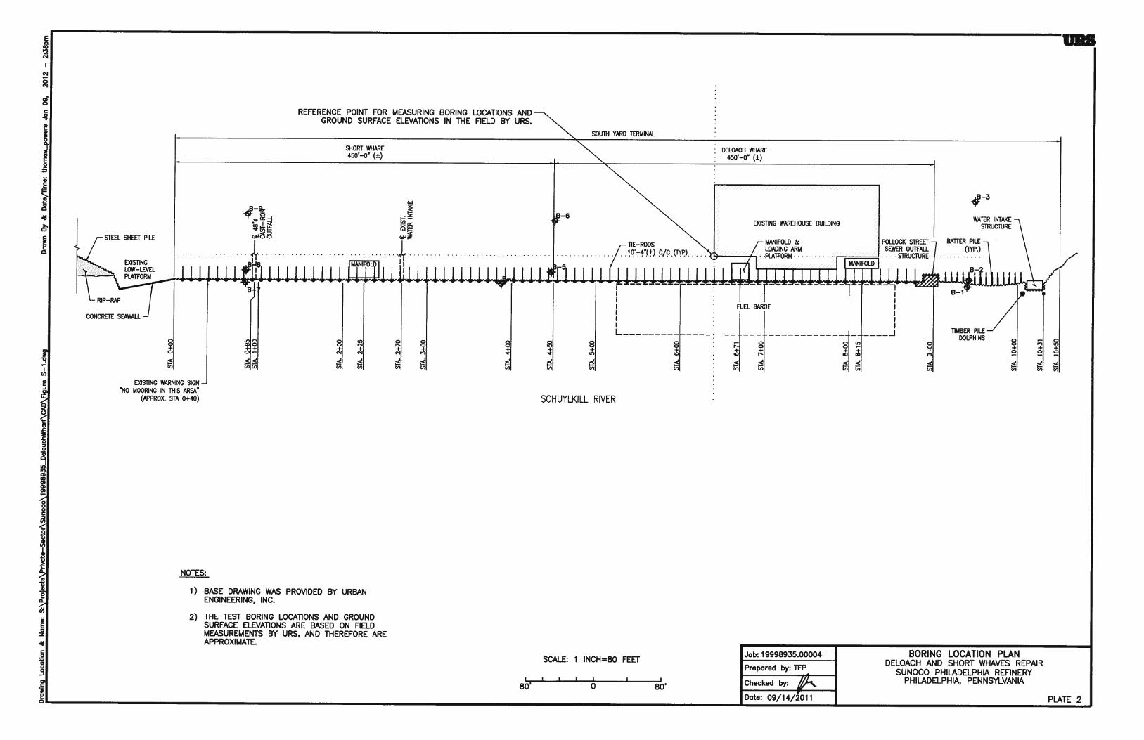
Based on the information from Urban Engineers, Inc. (UEI), the project designer, the proposed
repair work may consist of replacing existing bulkhead with a combination of sheetpiles, soldier
piles, anchoring systems consisting of concrete deadman or anchoring piles, placing stone riprap,
strengthening existing sheet piles, installing new sheet piles and new lateral support structures.
The Deloach and Short Wharfs are a part of the South Yard Terminal which is located on the
Schuylkill River, approximately 3¼ miles upriver of the confluence with the Delaware River and
approximately ¼ mile downriver of the Passyunk Avenue Bridge, in Philadelphia, Pennsylvania,
as shown in Plate 1 and Plate 2.
The South Yard Terminal is an approximately 1050 feet long wharf, consisting of a continuous
anchored steel sheet pile bulkhead and is separated into two designated berths, the Short Wharf
and Deloach Wharf. The Short Wharf and Deloach Wharf are situated on the upriver portion of
the terminal and measure approximately 450 feet long each. The Pollock Street sewage outfall
structure and water intake structures are located at approximately 150 feet of the downriver
portion of the terminal A deck structure, without an outshore bulkhead fascia exists at the upriver
end of the South Yard (beyond the 1050 feet length). The South Yard functions as a berth for
marine vessels, typically barges, for the loading and unloading of various petroleum based
products.
The original construction of the wharves at the South Yard Terminal varies along its length.
From Station 0+00 to approximately Station 1+05, the original wharf consisted of a timber pile
supported low level timber deck wharf structure with timber sheeting cut-off wall. From Station
1+05 to Station 9+00, the original wharf consisted of a steel HP-pile supported low level
concrete deck with a steel sheet pile cut off wall. Both types of wharf structures support a
concrete seawall retaining approximately 8 to 12 feet of fill material. The date of the original
construction of these wharf structures is not known. Circa 1980, the terminal structure was
modified with a continuous tied-back steel sheet pile bulkhead installed along the outshore face
of the wharf. The steel sheet pile bulkhead wall was anchored using anchors located inshore of
the face of the bulkhead. The anchor construction varies from steel sheet pile wall, to steel batter
pile supported reinforced concrete block, to reinforced concrete deadman along the length of the
terminal. The steel sheet pile bulkhead is protected by a timber fender system consisting of
timber fender piles spaced at approximately 10 feet 3 inches on centers along the length of the
bulkhead. The timber fender piles are attached to the steel sheet piling with chain and pad eye
connections. Located between the fender piles and steel sheet piling are two timber chocks and a
square rubber fender.
From Station 9+00 to Station 10+50, the original wharf appears to be a steel sheet pile bulkhead
with battered steel HP-pile anchors driven through penetrations in the steel sheets and connected
directly to the bulkhead. This area had previously supported a boat launch gantry crane system,
which was removed due to a bulkhead failure circa 1996.
The existing grade slopes gently downward towards the river and towards south. The elevations
of the existing grades are not available as of this writing. The elevation values reported here are
based on field measurements by URS, assuming the top of concrete at the northwest corner of
the warehouse building to be at El. 100 ft.
SECTIONSECTIONSECTIONSECTIONTHREE Site Geology
3-1
3. Section 3 THR EE Site Geolog y
A review of available geologic information indicates that the site is underlain by fine-grained
alluvial deposits which are underlain by the granular alluvial soils of the Trenton Gravel. The
Trenton Gravel formation generally consists of gravelly sand and interbedded sand and clay-silt
layers. The bedrock at the site consists of mica schist and gneiss of the Wissahickon Formation.
Within the refinery, there is generally a layer of man-made fill over the natural deposits.

SECTIONSECTIONSECTIONSECTIONFOUR Subsurface Conditions
4-1
4. Section 4 FOUR Subsu rface Conditio ns
The subsurface conditions at the site were explored by means of nine test borings, six of them
behind the bulkhead on land and three immediately in front of it in the river. The number and
locations of the borings were recommended by UEI. The locations of test borings are shown on
Plate 2, Site and Boring Location Plan. The borings were drilled to depths ranging from
approximately 80 to 98 feet below the existing grades behind the bulkheads. Logs of the test
borings are presented in Appendix A, together with a description of drilling and sampling
methods. Geotechnical laboratory test results are presented in Appendix B. Inferred subsurface
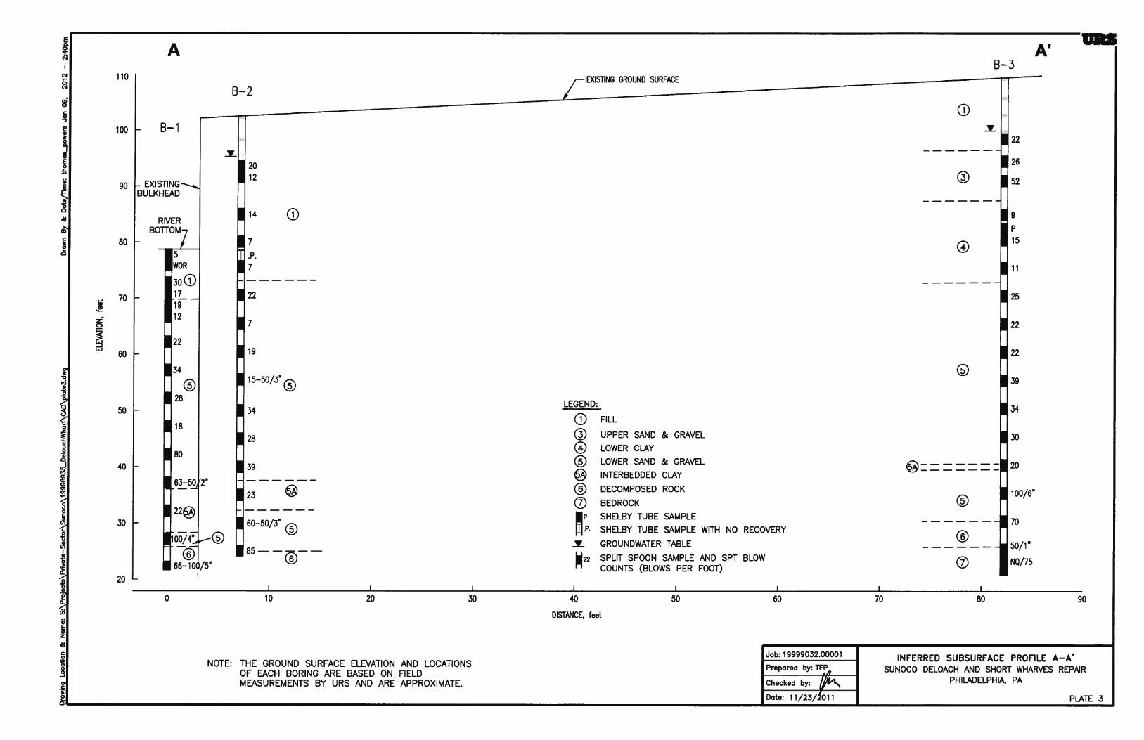
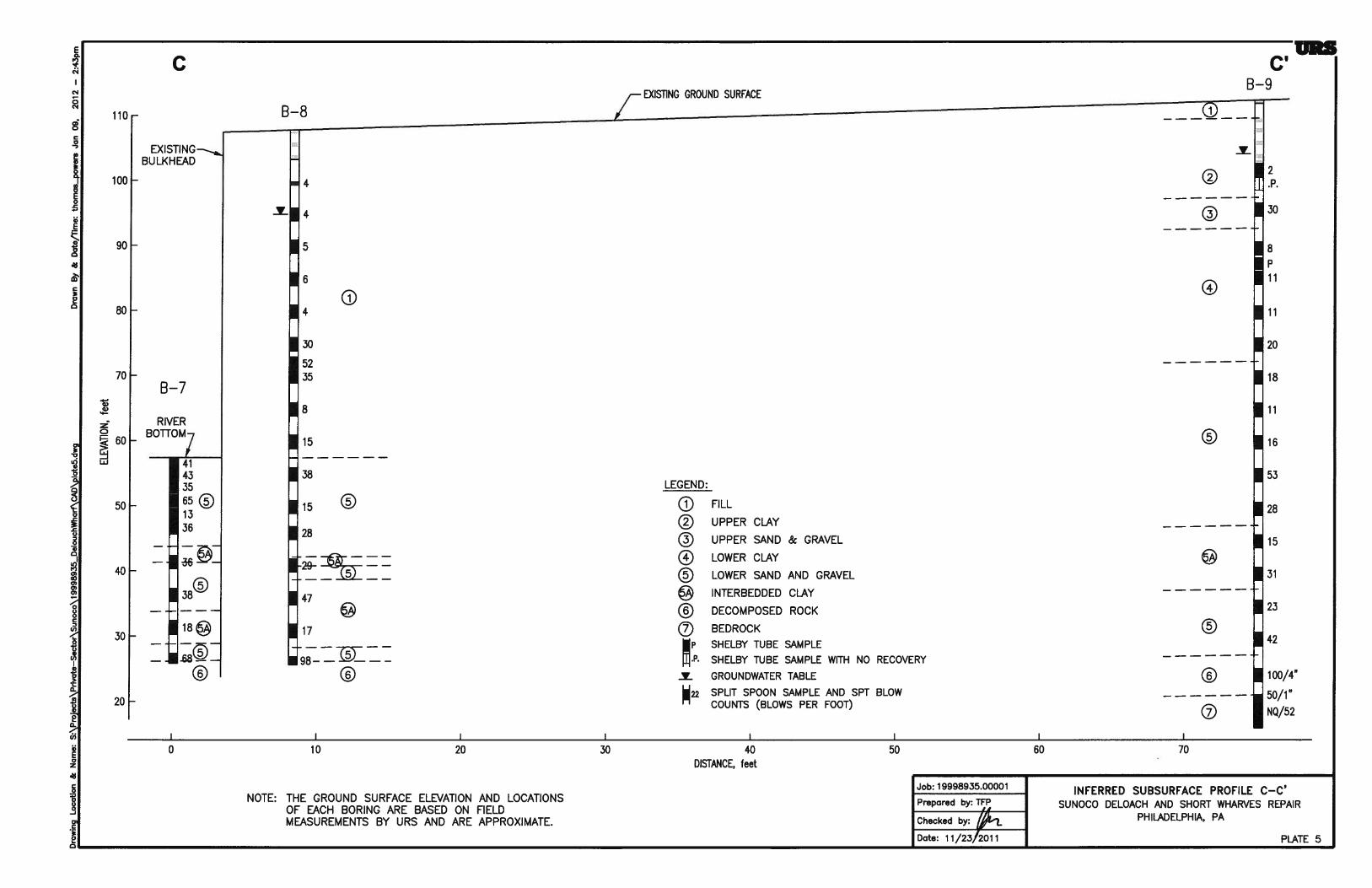
profiles are shown on Plates 3 through 5. The various strata encountered are described below.
4.1 STRATUM 1 – FILL
The fill stratum was encountered below the ground surface in all borings except Borings B-4 and
B-7.
In the three water borings (B-1, B-4, and B-7), the fill was only encountered in Boring B-1 below
the mud line, consisting of silty clay with concrete fragments and wood, with a thickness of
approximately 9 ft. The standard penetration test (SPT) N-values vary from weight of rods
(WOR) to 30 blows per foot (bpf), indicating an erratic density condition.
Significant amount of fill was encountered in the three borings behind the bulkhead (B-2, B-5,
and B-8) with a thickness varying between 32 ft in Boring B-2 and 53 ft in Boring B-8. The fill
consist of silty coarse to fine sand and gravel on the top, grading into silty medium to fine sand
with occasional concrete and brick fragments, and wood. The SPT N-values ranged between 2
to 52 bpf. Typically, the top of the fill stratum is judged to be in a dense condition, and the lower
portion of the fill in a loose to medium dense condition.
The fill was also encountered in the three land borings (Borings B-3, B-6, and B-9) with a
thickness of approximately 5 to 13 ft, consisting of silty coarse to fine sand and gravel with brick
and concrete fragments. Based on the resistance encountered during utility clearing using
vacuum extraction method (hydro-excavation), the fill in these three borings is judged to be in a
dense condition.
Results of five moisture content tests indicate a moisture content of 14 to 33 percent, averaging
24 percent. Grain-size distribution curves on selected fill samples are shown in Appendix B.
Corrosivity testing on one sample indicates pH value of 7.8, resistivity of 8,200 Ω-cm, and no
detectable chloride, sulfate, and sulfide.
Organic vapor concentration of soil samples varies from 14 to over 10,000 parts per million
(ppm). The highest reading was recorded in Borings B-3 and B-8.
4.2 STRATUM 2 – UPPER CLAY
This stratum was encountered right below Stratum 1 in Borings B-6 and B-9 with a thickness of
approximately 4 and 12 ft. The soils consist of gray fine sandy silty clay. The SPT N-value was
2 bpf. Based on the resistance encountered hydro-excavation, the soils are judged to be firm to
stiff condition.
SECTIONSECTIONSECTIONSECTIONFOUR Subsurface Conditions
4-2
Results of one moisture content test indicate a moisture content of 24 percent. The grain size
distribution curve is shown in Appendix B. Results of an Atterberg limit test indicate a liquid
limit of 24 percent and a plastic limit of 15 percent.
Organic vapor concentration of soil samples varies from 340 to 800 ppm.
4.3 STRATUM 3 – UPPER SAND AND GRAVEL
This stratum was encountered in Borings B-3, B-6, and B-9 below Stratum 1 or Stratum 2, with a
thickness of approximately 5 to 9 ft. The soils consist of gray coarse to fine sand and gravel with
trace silt. The SPT N-values range from 23 to 52 bpf, averaging 33 bpf, indicative of a medium
dense to dense condition.
Results of one moisture content test indicate a moisture content of 9 percent. The grain size
distribution curve is shown in Appendix B.
No organic vapor concentration was detected in the soil samples in this stratum.
4.4 STRATUM 4 – LOWER CLAY
This stratum was encountered below Stratum 1 and Stratum 3 in Borings B-3 through B-6, and
B-9. The soils consist of gray sandy silty clay to sandy silt. The thickness of this stratum is
approximately 1 ft in Boring B-4, and 12 to 21 ft in other borings. The SPT N-values range from
2 to 20 bpf. The Pocket Penetrometer Resistance (PPR) values typically vary from 0.5 to 1.5 tsf,
indicative of a firm to stiff consistency.
Results of moisture content tests indicate that the moisture contents ranged from 24 to 37
percent, averaging 30 percent. Grain size distribution curves are shown in Appendix B. Results
of five Atterberg limit tests indicate liquid limits ranging from 24 to 46 percent and plastic limits
from 20 to 27 percent.
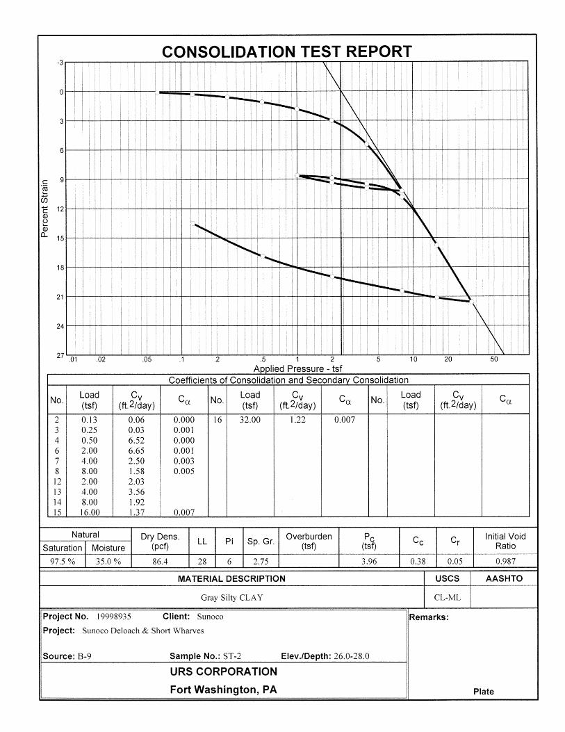
Three unconsolidated-undrained (UU) triaxial compression tests indicate undrained shear
strengths of 500 to 1,700 psf, averaging 1,200 psf, indicative of a firm to stiff consistency. Two
consolidation tests indicate preconsolidation pressure of approximately 4 tsf and 5.6 tsf, with
compression ratios of 0.19 and 0.17, and recompression ratios of 0.025 and 0.015 (all strain
based).
No organic vapor concentration was detected in the soil samples in this stratum.
4.5 STRATUM 5 – LOWER SAND AND GRAVEL
This stratum was encountered beneath Stratum 1 or Stratum 4 in all borings, extending to a depth
of approximately 79 to 87 ft below grade. The soils consist of brown medium to fine sand on
the top of this stratum, grading into gray and brown silty coarse to fine sand with varying
amounts of gravel. SPT N-values range from 7 to 113 bpf. The top portion of the stratum is
judged to be in a medium dense condition, and lower portion in a dense to very dense condition.
There are layers of interbeded clay within this stratum, which is described in detail in Section
4.6.
SECTIONSECTIONSECTIONSECTIONFOUR Subsurface Conditions
4-3
Results of moisture content tests indicate that the moisture contents ranged from 4 to 23 percent,
averaging 11 percent. Grain size distribution curves are shown in Appendix B.
No organic vapor concentration was detected in the soil samples in this stratum.
4.6 STRATUM 5A – INTERBEDDED CLAY
This stratum was encountered within Stratum 5. The thickness of the layers ranges from
approximately 1 ft to 18.5 ft. Typically, the top of the layer is encountered below a depth of 60
ft. The soils consist of gray clay with thin partings (less than 1/32 inch in thickness) of very fine
sand. SPT values of the soils range from 11 to 47 bpf, averaging 25 bpf. The PPR values vary
from 1 to 3 tsf, indicative of a stiff to very stiff consistency.
Results of moisture content tests indicate that the moisture contents ranged from 8 to 44 percent.
Grain size distribution curves are shown in Appendix B.
No organic vapor concentration was detected in the soil samples in this stratum.
4.7 STRATUM 6 – DECOMPOSED ROCK
This stratum was encountered beneath Stratum 5 or 5A in all borings. This stratum was not fully
penetrated in all borings except Borings B-3 and B-9 with a thickness of 4.5 to 6 ft. The
decomposed rock consisted of light gray micaceous silty course to fine sand and gravel-size rock
fragments. Relict rock structure was apparent in the soil samples. The SPT values are more than
50 bpf, indicative of a very dense condition.
4.8 STRATUM 7 – BEDROCK
The bedrock was cored in two test borings, B-3 and B-9, with a core length of 5 feet each. The
bedrock consists of moderately weathered mica schist. The core runs had a recovery of 75 and
52 percent, and the Rock Quality Designation (RQD) of 12 and 13 percent.
4.9 GROUNDWATER
As a part of the investigation, groundwater monitoring well were installed in Borings B-2, B-3,
B-5, B-6, B-8, and B-9. The groundwater readings are tabulated in each boring log. The
groundwater was observed to be at 7 to 12 ft below grade, corresponding to El. 94 to El. 104
during the field investigation in August 2011. Higher elevations were observed in the borings in
the northern portion of the site (B-8 and B-9). It should be noted that groundwater levels are
subject to seasonal and long-term variations due to tidal, climatic, and man-made influences.

SECTIONSECTIONSECTIONSECTIONFIVE Geotechnical Evaluation
5-1
5. Section 5 F IVE Geot echn ical Conditio ns
The subsurface of the project site consists of six different soils strata as described in Section 4.
From land side to the river, the soil stratigraphy above Stratum 5 soils change drastically, as the
fill thickness increases significantly towards the river. This is illustrated by the three inferred
subsurface profiles (Plates 3, 4, and 5).
Per our discussion with UEI, the proposed repair will likely consist of new sheetpiles and soldier
piles in the front of the bulkhead, and anchors on the land side to provide lateral support. The
anchors could consist of either concrete deadman or battered driven piles, or a combination of
both. The piles that are being considered are HP12x53, HP12x74, HP14x73, and 14-inch and
16-inch outside-diameter (OD) open-end steel pipe piles with ½-inch wall thickness. Due to the
presence of dense sand and gravel, HP12x53 piles may be too light to penetrate through in order
to derive the required tension capacity. The design recommendations are provided in Section 6.
SECTIONSECTIONSECTIONSECTIONSIX Recommendations
6-1
6. Section 6 SIX Reco mmend ation s
Recommendations pertaining to the design and construction of foundations and earthworks for
the proposed repairs are presented below.
6.1 FOUNDATIONS
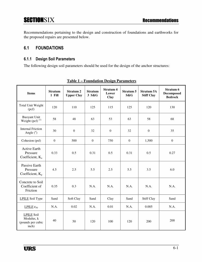
6.1.1 Design Soil Parameters
The following design soil parameters should be used for the design of the anchor structures:
Table 1 – Foundation Design Parameters
Items Stratum
1 Fill
Stratum 2
Upper Clay
Stratum
3 S&G
Stratum 4
Lower
Clay
Stratum 5
S&G
Stratum 5A
Stiff Clay
Stratum 6
Decomposed
Bedrock
Total Unit Weight
(pcf) 120 110 125 115 125 120 130
Buoyant Unit
Weight (pcf) (1)
58 48 63 53 63 58 68
Internal Friction
Angle (o)
30 0 32 0 32 0 35
Cohesion (psf) 0 500 0 750 0 1,500 0
Active Earth
Pressure
Coefficient, Ka
0.33 0.5 0.31 0.5 0.31 0.5 0.27
Passive Earth
Pressure
Coefficient, Kp
4.5 2.5 5.5 2.5 5.5 3.5 6.0
Concrete to Soil
Coefficient of
Friction
0.35 0.3 N.A. N.A. N.A. N.A. N.A.
LPILE Soil Type Sand Soft Clay Sand Clay Sand Stiff Clay Sand
LPILE ε50 N.A. 0.02 N.A. 0.01 N.A. 0.005 N.A.
LPILE Soil
Modulus, k
(pounds per cubic
inch)
40 50 120 100 120 200 200

SECTIONSECTIONSECTIONSECTIONSIX Recommendations
6-2
6.1.2 Pile Foundations
Design: It is understood that the piles to be used may consist of HP 12x74, HP14x73, and 14-
inch and 16-inch OD open-end pipe piles with ½ inch walls. The piles should have a minimum
yield stress of 36 ksi and meeting requirements of ASTM A36 or A572 steel. All welds (e.g.,
splices) in the pile should be full-penetration butt welds conforming to the current edition of the
Structural Welding Code, D1.1, American Welding Society.
The following design capacities may be used. The tension capacity requires a minimum length
of 80 ft below the grade behind the bulkhead.
Table 1 – Pile Design Parameters - Piles on Landside
Pile Type HP12x74 HP14x73
14-inch OD
Open-end
Pipe
16-inch OD
Open-end
Pipe
Allowable Capacity –
Compression (tons) 80 90 80 95
Allowable Capacity –
Tension (tons) 40 45 40 45
Table 2 – Pile Design Parameters - Piles on Waterside
Pile Type HP12x74 HP14x73
14-inch OD
Open-end
Pipe
16-inch OD
Open-end
Pipe
Allowable Capacity –
Compression (tons) 40 40 40 40
Allowable Capacity –
Tension (tons) 10 10 10 12
The allowable compression and tension capacities of the pile may be increased by 33 percent for
short term loading due to wind and earthquake.
Construction: All piles are expected to be seated into the decomposed rock of Stratum 6 to
derive the design capacities. The contractor shall select a hammer capable of delivering
sufficient energy to pile tips while not exceeding practical refusal for the hammer and while not
exceeding 90 percent of the yield stress of the pile during driving. The Contractor should submit
pile hammer and wave equation analysis for the Geotechnical Engineer (URS) to review prior to
starting work. The piles are expected to be driven to a depth of approximately 80 feet below the
grade behind the bulkhead to derive the required capacities.
All piles should be installed within 3 inches of design location and should not be more than 2
percent out of plumb. Piles should not be collapsed, bent, or otherwise damaged. Any non-
conforming piles should be replaced by the contractor at no cost to the owner.
SECTIONSECTIONSECTIONSECTIONSIX Recommendations
6-3
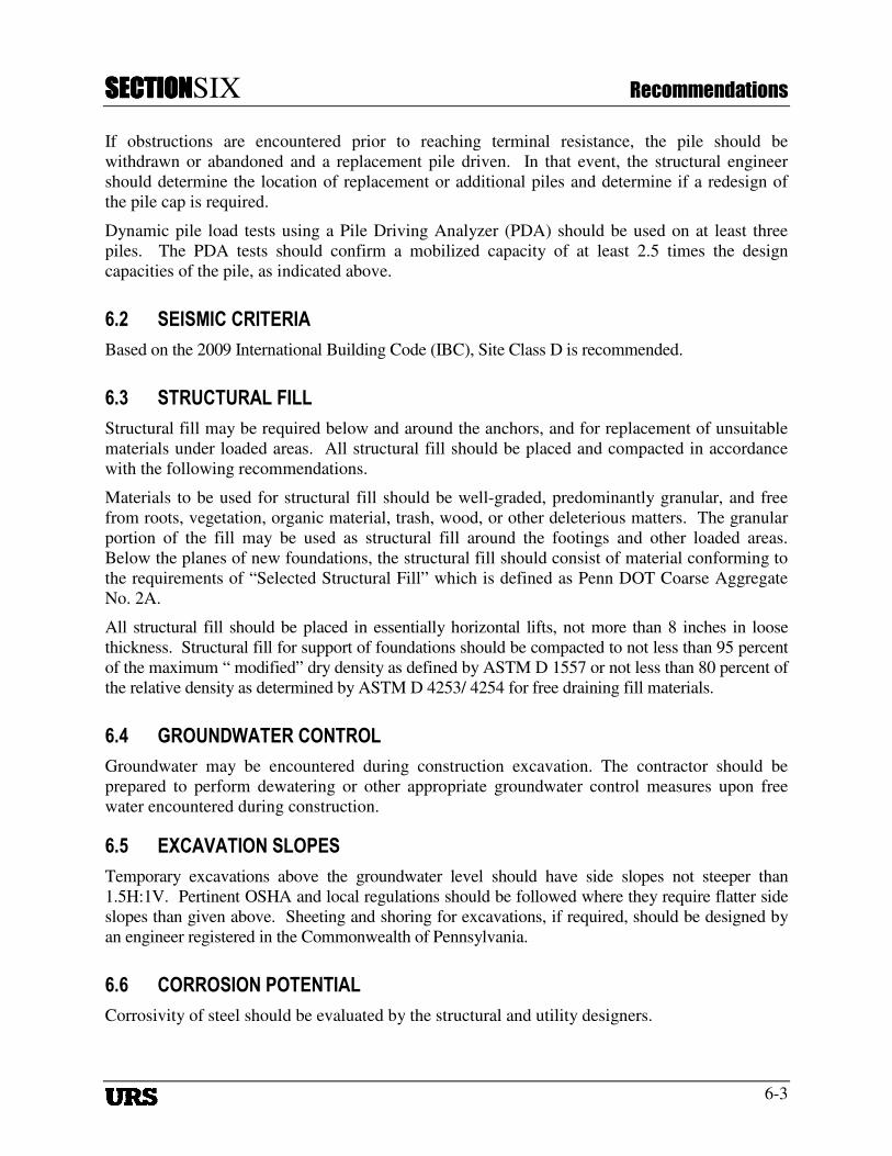
If obstructions are encountered prior to reaching terminal resistance, the pile should be
withdrawn or abandoned and a replacement pile driven. In that event, the structural engineer
should determine the location of replacement or additional piles and determine if a redesign of
the pile cap is required.
Dynamic pile load tests using a Pile Driving Analyzer (PDA) should be used on at least three
piles. The PDA tests should confirm a mobilized capacity of at least 2.5 times the design
capacities of the pile, as indicated above.
6.2 SEISMIC CRITERIA
Based on the 2009 International Building Code (IBC), Site Class D is recommended.
6.3 STRUCTURAL FILL
Structural fill may be required below and around the anchors, and for replacement of unsuitable
materials under loaded areas. All structural fill should be placed and compacted in accordance
with the following recommendations.
Materials to be used for structural fill should be well-graded, predominantly granular, and free
from roots, vegetation, organic material, trash, wood, or other deleterious matters. The granular
portion of the fill may be used as structural fill around the footings and other loaded areas.
Below the planes of new foundations, the structural fill should consist of material conforming to
the requirements of “Selected Structural Fill” which is defined as Penn DOT Coarse Aggregate
No. 2A.
All structural fill should be placed in essentially horizontal lifts, not more than 8 inches in loose
thickness. Structural fill for support of foundations should be compacted to not less than 95 percent
of the maximum “ modified” dry density as defined by ASTM D 1557 or not less than 80 percent of
the relative density as determined by ASTM D 4253/ 4254 for free draining fill materials.
6.4 GROUNDWATER CONTROL
Groundwater may be encountered during construction excavation. The contractor should be
prepared to perform dewatering or other appropriate groundwater control measures upon free
water encountered during construction.
6.5 EXCAVATION SLOPES
Temporary excavations above the groundwater level should have side slopes not steeper than
1.5H:1V. Pertinent OSHA and local regulations should be followed where they require flatter side
slopes than given above. Sheeting and shoring for excavations, if required, should be designed by
an engineer registered in the Commonwealth of Pennsylvania.
6.6 CORROSION POTENTIAL
Corrosivity of steel should be evaluated by the structural and utility designers.
SECTIONSECTIONSECTIONSECTIONSIX Recommendations
6-4
6.7 CONSTRUCTION OBSERVATION
It is recommended that full-time construction observation be provided during foundation and
earthworks construction by URS Corporation or a qualified geotechnical engineering firm that is
familiar with the subsurface conditions and the foundation design criteria. The items which
should be observed, monitored, and/or tested include subgrade preparation, placement and
compaction of structural fill, and pile construction.
SECTIONSECTIONSECTIONSECTIONSEVEN Limitations
7-1
7. Section 7 SEVEN Limit ations
The services described in this report were provided in accordance with reasonable and accepted
engineering practice. No warranty or guarantee, expressed or implied, is intended. The
conclusions and recommendations are based on the assumptions that the subsurface conditions
do not deviate appreciably from those encountered in the test borings and pits and that the loads
are similar to these given in the project description. If the structure is moved or loads have
changed, URS should be given the opportunity to modify recommendations accordingly. The
conclusions and recommendations are also based on competent field engineering, monitoring,
and testing during construction. The recommendations presented in this report are solely for the
use of our client for the design of this particular project. Any re-use of this document,
particularly by third parties, without the express written permission of URS is solely at their own
risk.
Plates


Appendix A
Subsurface Exploration

Appendix A
Subsurface Exploration
A-1
The subsurface exploration consisted of nine test borings located as shown on Plate 2, Site and
Boring Location Plan. The borings were drilled between July 19 and August 26, 2011, by
Parratt-Wolff Inc., East Syracuse, New York. The test borings were conducted under full-time
technical supervision of URS. The test borings were located in the field by URS with assistance
from Sunoco personnel. Utility clearance was conducted by Sunoco using vacuum extraction
techniques (hydro-excavation) at the top 10 feet of each boring on land. Test borings locations
and elevations were interpreted based on field measurements by URS and are therefore
approximate. The northwest corner of the existing maintenance warehouse was taken as El. +100
feet.
The soil conditions at the top ten feet of each land boring were evaluated through probing using a
hand probe. Soil samples were obtained with a hand auger at various depths.
The test borings were performed using a truck-mounted CME 75 drilling rig and were advanced
by mud-rotary drilling techniques and 4 inch OD casings. Samples of the subsoils were obtained
from the borings for identification and classification purposes by means of a 2-inch O.D. split-
barrel sampler driven 24 inches by a 140-pound hammer freely falling 30 inches (the Standard
Penetration Test, ASTM D 1586). The number of hammer blows required driving the sampler
during the interval from 6 to 18 inches, or fraction thereof, is reported on the test boring logs as
the sampling resistance. Relatively undisturbed samples of fine-grained soils were recovered
using a 3-inch O.D. thin-walled Osterberg tube sampler in general accordance with ASTM D
1587.
NQ-size rock cores (1-7/8-inch diameter), approximately 5 feet in total length were obtained in
two borings upon encountering bedrock. After coring, the Rock Quality Designation (RQD) was
determined as the total length of all naturally segmented recovered rock core segments equal to
or greater than 4 inches in length divided by the total length of each core run, expressed as a
percentage. The RQD and the percent core recovery are presented on the boring logs.
Organic vapor monitoring was conducted during hydro-excavation and drilling operation by
URS using a MiniRAE PID five gas monitor. The values of concentrations of organic vapor (in
ppm) are shown on the boring logs under “Other Tests”.
Where fine-grained materials were encountered, Pocket Penetrometer Resistance (PPR) readings
were taken to obtain an indication of the unconfined compressive strength of cohesive soils.
These values are shown on the boring logs under "Pocket Penetrometer (tsf)".
At the completion of the test borings, the boreholes were backed-filled with bentonite/cement
grout.
A "Key to Soil Symbols and Terms" used in this report is included on page A-2. The logs of the
test borings are presented on Pages A-3 through A-29.


5
WOR
30
17
19
12
22
SS
SS
SS
SS
SS
SS
SS
0.5
0.5
1.0
78.7
69.7
Top of Bulkhead
Mudline
Firm gray silty CLAY, trace fine sand (Fill)
- wood and concrete fragments
(Stratum 1)Medium dense to dense brown silty medium to fine SAND
- thin layers of silty clay
(Stratum 5)- trace silt
(Continue on Sheet 2 of 3)
LIQ
UID
LOCATIONDATE
ST
RA
TU
M
See Plate 2
Sheet 1 of 3
Drilling Method:
SA
MP
LES
ft., After
ft., After
ft., After
ft., After
Sunoco Deloach and Short Wharves Repair
LIM
IT,
%
hrs.
hrs.
hrs.
hrs.
105.7
19998935.0000184.0 ft.
PLA
ST
IC
SURFACE ELEVATION11
/27/
11 B
OR
LOG
R 1
9998
935
-SH
OR
T_D
ELO
AC
H_W
HA
RV
ES
.GP
J
LOG of BORING No. B-1
Water Depth:
Mud Rotary
ELE
VA
TIO
N
Completion Depth:
Project Name:
RE
SIS
TA
NC
E
SeeNotes
OT
HE
R T
ES
TS
08/18/11
0
5
10
15
20
25
30
35
40
LIM
IT,
%
Project No.:
DE
PT
H,
FT
.
A-3
Completion Depth:
DESCRIPTION
CO
NT
EN
T,
%
hrs.
hrs.
hrs.
hrs.
SURFACE ELEVATION
Water Depth:
PLA
ST
IC
Project No.:
SA
MP
LE T
YP
E
(TS
F)
ft., After
ft., After
ft., After
ft., After
PO
CK
ET
WA
TE
R
DATE
Drilling Method:
LIQ
UID
PE
NE
TR
OM
ET
ER
LOCATION
Project Name:
SA
MP
LIN
G

34
28
18
80
63-50/2"
22
100/4"
66- 100/5"
SS
SS
SS
SS
SS
SS
SS
SS
1.5-2.0
36.2
28.2
25.7
21.7
Medium dense to dense brown coarse to fine SAND withvarying amounts of gravel, trace silt
- thin layers of silty clay
- sand and gravel
(Stratum 5)
Stiff to very stiff gray CLAY with thin partings of fine sand
(Stratum 5A)- very dense gravel
(Stratum 5)Very dense micaceous coarse to fine SAND andgravel-sized rock fragments (Decomposed Rock)
(Stratum 6)
(Continue on Sheet 3 of 3)
LIQ
UID
LOCATIONDATE
ST
RA
TU
M
See Plate 2
Sheet 2 of 3
Drilling Method:
SA
MP
LES
ft., After
ft., After
ft., After
ft., After
Sunoco Deloach and Short Wharves Repair
LIM
IT,
%
hrs.
hrs.
hrs.
hrs.
105.7
19998935.0000184.0 ft.
PLA
ST
IC
SURFACE ELEVATION11
/27/
11 B
OR
LOG
R 1
9998
935
-SH
OR
T_D
ELO
AC
H_W
HA
RV
ES
.GP
J
LOG of BORING No. B-1
Water Depth:
Mud Rotary
ELE
VA
TIO
N
Completion Depth:
Project Name:
RE
SIS
TA
NC
E
SeeNotes
OT
HE
R T
ES
TS
08/18/11
45
50
55
60
65
70
75
80
85
LIM
IT,
%
Project No.:
DE
PT
H,
FT
.
A-4
Completion Depth:
DESCRIPTION
CO
NT
EN
T,
%
hrs.
hrs.
hrs.
hrs.
SURFACE ELEVATION
Water Depth:
PLA
ST
IC
Project No.:
SA
MP
LE T
YP
E
(TS
F)
ft., After
ft., After
ft., After
ft., After
PO
CK
ET
WA
TE
R
DATE
Drilling Method:
LIQ
UID
PE
NE
TR
OM
ET
ER
LOCATION
Project Name:
SA
MP
LIN
G

Notes:1. The drilling began at approximately 27 ft below the topof the bulkhead. All depths indicated in this log are fromthe top of the bulkhead.2. Unless otherwise indicated, numerical values under"Other Tests" are PID readings from head space of samplejars (in ppm).
LIQ
UID
LOCATIONDATE
ST
RA
TU
M
See Plate 2
Sheet 3 of 3
Drilling Method:
SA
MP
LES
ft., After
ft., After
ft., After
ft., After
Sunoco Deloach and Short Wharves Repair
LIM
IT,
%
hrs.
hrs.
hrs.
hrs.
105.7
19998935.0000184.0 ft.
PLA
ST
IC
SURFACE ELEVATION11
/27/
11 B
OR
LOG
R 1
9998
935
-SH
OR
T_D
ELO
AC
H_W
HA
RV
ES
.GP
J
LOG of BORING No. B-1
Water Depth:
Mud Rotary
ELE
VA
TIO
N
Completion Depth:
Project Name:
RE
SIS
TA
NC
E
SeeNotes
OT
HE
R T
ES
TS
08/18/11
90
95
100
105
110
115
120
125
130
LIM
IT,
%
Project No.:
DE
PT
H,
FT
.
A-5
Completion Depth:
DESCRIPTION
CO
NT
EN
T,
%
hrs.
hrs.
hrs.
hrs.
SURFACE ELEVATION
Water Depth:
PLA
ST
IC
Project No.:
SA
MP
LE T
YP
E
(TS
F)
ft., After
ft., After
ft., After
ft., After
PO
CK
ET
WA
TE
R
DATE
Drilling Method:
LIQ
UID
PE
NE
TR
OM
ET
ER
LOCATION
Project Name:
SA
MP
LIN
G

20
12
14
7
.P.
7
22
7
19
AU
AU
SS
SS
SS
SS
.P.
SS
SS
SS
SS
73.0
Dense brown silty coarse to fine SAND and GRAVEL(Fill)
- trace wood chips
- trace wood chips, concrete fragments
- firm to stiff brown silty clay/clayey silt, trace fine sand
- brown medium to fine sand, trace silt, wood chips
(Stratum 1)
Medium dense to dense brown coarse to fine SAND withvarying amounts of gravel, trace silt
- sandy silty clay
(Stratum 5)(Continue on Sheet 2 of 3)
14
LIQ
UID
LOCATIONDATE
ST
RA
TU
M
See Plate 2
Sheet 1 of 3
Drilling Method:
SA
MP
LES
ft., After
ft., After
ft., After
ft., After
Sunoco Deloach and Short Wharves Repair
LIM
IT,
%
hrs.
hrs.
hrs.
hrs.
104.5
19998935.0000180.3 ft.
PLA
ST
IC
SURFACE ELEVATION11
/27/
11 B
OR
LOG
R 1
9998
935
-SH
OR
T_D
ELO
AC
H_W
HA
RV
ES
.GP
J
LOG of BORING No. B-2
Water Depth:
Mud Rotary
ELE
VA
TIO
N
Completion Depth:
Project Name:
RE
SIS
TA
NC
E
SeeNotes
OT
HE
R T
ES
TS
08/16/11
0
5
10
15
20
25
30
35
40
LIM
IT,
%
Project No.:
DE
PT
H,
FT
.
A-6
Completion Depth:
DESCRIPTION
CO
NT
EN
T,
%
hrs.
hrs.
hrs.
hrs.
SURFACE ELEVATION
Water Depth:
PLA
ST
IC
Project No.:
SA
MP
LE T
YP
E
(TS
F)
ft., After
ft., After
ft., After
ft., After
PO
CK
ET
WA
TE
R
DATE
Drilling Method:
LIQ
UID
PE
NE
TR
OM
ET
ER
LOCATION
Project Name:
SA
MP
LIN
G
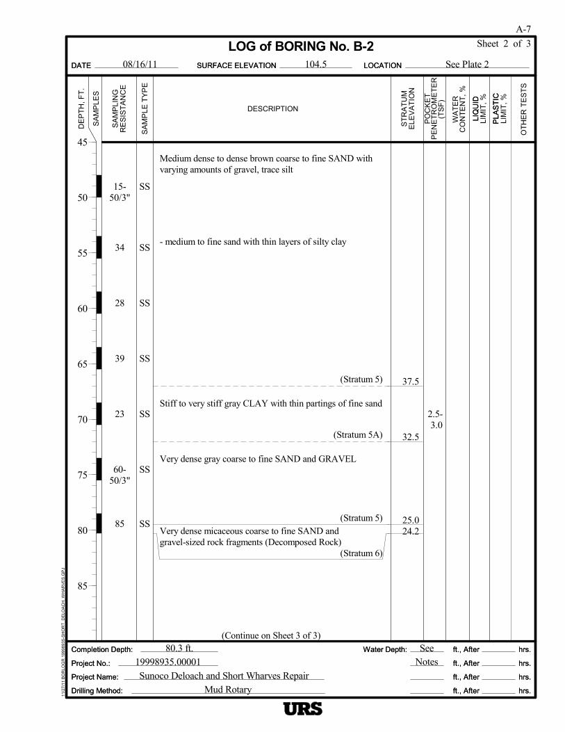
15-50/3"
34
28
39
23
60-50/3"
85
SS
SS
SS
SS
SS
SS
SS
2.5- 3.0
37.5
32.5
25.024.2
Medium dense to dense brown coarse to fine SAND withvarying amounts of gravel, trace silt
- medium to fine sand with thin layers of silty clay
(Stratum 5)
Stiff to very stiff gray CLAY with thin partings of fine sand
(Stratum 5A)
Very dense gray coarse to fine SAND and GRAVEL
(Stratum 5)Very dense micaceous coarse to fine SAND andgravel-sized rock fragments (Decomposed Rock)
(Stratum 6)
(Continue on Sheet 3 of 3)
LIQ
UID
LOCATIONDATE
ST
RA
TU
M
See Plate 2
Sheet 2 of 3
Drilling Method:
SA
MP
LES
ft., After
ft., After
ft., After
ft., After
Sunoco Deloach and Short Wharves Repair
LIM
IT,
%
hrs.
hrs.
hrs.
hrs.
104.5
19998935.0000180.3 ft.
PLA
ST
IC
SURFACE ELEVATION11
/27/
11 B
OR
LOG
R 1
9998
935
-SH
OR
T_D
ELO
AC
H_W
HA
RV
ES
.GP
J
LOG of BORING No. B-2
Water Depth:
Mud Rotary
ELE
VA
TIO
N
Completion Depth:
Project Name:
RE
SIS
TA
NC
E
SeeNotes
OT
HE
R T
ES
TS
08/16/11
45
50
55
60
65
70
75
80
85
LIM
IT,
%
Project No.:
DE
PT
H,
FT
.
A-7
Completion Depth:
DESCRIPTION
CO
NT
EN
T,
%
hrs.
hrs.
hrs.
hrs.
SURFACE ELEVATION
Water Depth:
PLA
ST
IC
Project No.:
SA
MP
LE T
YP
E
(TS
F)
ft., After
ft., After
ft., After
ft., After
PO
CK
ET
WA
TE
R
DATE
Drilling Method:
LIQ
UID
PE
NE
TR
OM
ET
ER
LOCATION
Project Name:
SA
MP
LIN
G
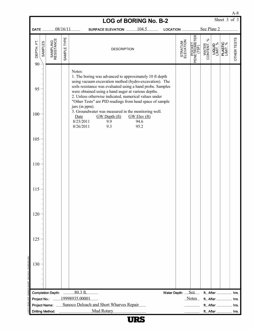
Notes:1. The boring was advanced to approximately 10 ft depthusing vacuum excavation method (hydro-excavation). Thesoils resistance was evaluated using a hand probe. Sampleswere obtained using a hand auger at various depths.2. Unless otherwise indicated, numerical values under"Other Tests" are PID readings from head space of samplejars (in ppm).3. Groundwater was measured in the monitoring well.
Date GW Depth (ft) GW Elev (ft) 8/23/2011 9.9 94.6 8/26/2011 9.3 95.2
LIQ
UID
LOCATIONDATE
ST
RA
TU
M
See Plate 2
Sheet 3 of 3
Drilling Method:
SA
MP
LES
ft., After
ft., After
ft., After
ft., After
Sunoco Deloach and Short Wharves Repair
LIM
IT,
%
hrs.
hrs.
hrs.
hrs.
104.5
19998935.0000180.3 ft.
PLA
ST
IC
SURFACE ELEVATION11
/27/
11 B
OR
LOG
R 1
9998
935
-SH
OR
T_D
ELO
AC
H_W
HA
RV
ES
.GP
J
LOG of BORING No. B-2
Water Depth:
Mud Rotary
ELE
VA
TIO
N
Completion Depth:
Project Name:
RE
SIS
TA
NC
E
SeeNotes
OT
HE
R T
ES
TS
08/16/11
90
95
100
105
110
115
120
125
130
LIM
IT,
%
Project No.:
DE
PT
H,
FT
.
A-8
Completion Depth:
DESCRIPTION
CO
NT
EN
T,
%
hrs.
hrs.
hrs.
hrs.
SURFACE ELEVATION
Water Depth:
PLA
ST
IC
Project No.:
SA
MP
LE T
YP
E
(TS
F)
ft., After
ft., After
ft., After
ft., After
PO
CK
ET
WA
TE
R
DATE
Drilling Method:
LIQ
UID
PE
NE
TR
OM
ET
ER
LOCATION
Project Name:
SA
MP
LIN
G
22
26
52
9
P
15
11
25
22
2542
AU
AU
AU
AU
SS
SS
SS
SS
P
SS
SS
SS
SS
1.25-1.5
1.5-1.75
96.4
87.4
72.9
26.3
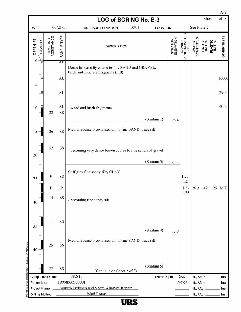
Dense brown silty coarse to fine SAND and GRAVEL,brick and concrete fragments (Fill)
- wood and brick fragments
(Stratum 1)
Medium dense brown medium to fine SAND, trace silt
- becoming very dense brown coarse to fine sand and gravel
(Stratum 3)
Stiff gray fine sandy silty CLAY
- becoming fine sandy silt
(Stratum 4)
Medium dense brown medium to fine SAND, trace silt
(Stratum 5)(Continue on Sheet 2 of 3)
10000
2900
4000
M T C
LIQ
UID
LOCATIONDATE
ST
RA
TU
M
See Plate 2
Sheet 1 of 3
Drilling Method:
SA
MP
LES
ft., After
ft., After
ft., After
ft., After
Sunoco Deloach and Short Wharves Repair
LIM
IT,
%
hrs.
hrs.
hrs.
hrs.
109.4
19998935.0000188.6 ft.
PLA
ST
IC
SURFACE ELEVATION11
/27/
11 B
OR
LOG
R 1
9998
935
-SH
OR
T_D
ELO
AC
H_W
HA
RV
ES
.GP
J
LOG of BORING No. B-3
Water Depth:
Mud Rotary
ELE
VA
TIO
N
Completion Depth:
Project Name:
RE
SIS
TA
NC
E
SeeNotes
OT
HE
R T
ES
TS
07/21/11
0
5
10
15
20
25
30
35
40
LIM
IT,
%
Project No.:
DE
PT
H,
FT
.
A-9
Completion Depth:
DESCRIPTION
CO
NT
EN
T,
%
hrs.
hrs.
hrs.
hrs.
SURFACE ELEVATION
Water Depth:
PLA
ST
IC
Project No.:
SA
MP
LE T
YP
E
(TS
F)
ft., After
ft., After
ft., After
ft., After
PO
CK
ET
WA
TE
R
DATE
Drilling Method:
LIQ
UID
PE
NE
TR
OM
ET
ER
LOCATION
Project Name:
SA
MP
LIN
G
22
39
34
30
20
100/6"
70
50/1"
NQ75
SS
SS
SS
SS
SS
SS
SS
SS
NQ
1.5-1.75
57.9
40.939.9
30.4
25.9
20.8
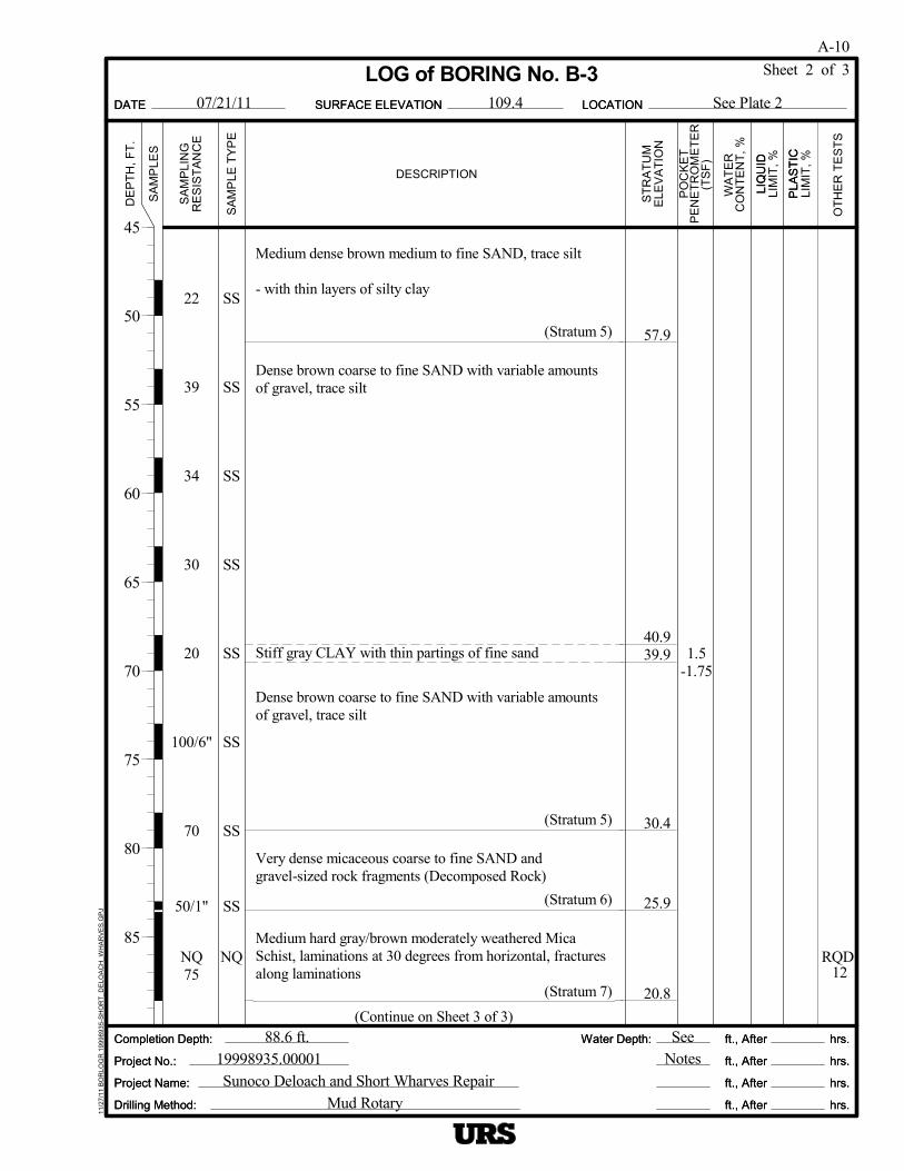
Medium dense brown medium to fine SAND, trace silt
- with thin layers of silty clay
(Stratum 5)
Dense brown coarse to fine SAND with variable amountsof gravel, trace silt
Stiff gray CLAY with thin partings of fine sand
Dense brown coarse to fine SAND with variable amountsof gravel, trace silt
(Stratum 5)
Very dense micaceous coarse to fine SAND andgravel-sized rock fragments (Decomposed Rock)
(Stratum 6)
Medium hard gray/brown moderately weathered MicaSchist, laminations at 30 degrees from horizontal, fracturesalong laminations
(Stratum 7)
(Continue on Sheet 3 of 3)
RQD 12
LIQ
UID
LOCATIONDATE
ST
RA
TU
M
See Plate 2
Sheet 2 of 3
Drilling Method:
SA
MP
LES
ft., After
ft., After
ft., After
ft., After
Sunoco Deloach and Short Wharves Repair
LIM
IT,
%
hrs.
hrs.
hrs.
hrs.
109.4
19998935.0000188.6 ft.
PLA
ST
IC
SURFACE ELEVATION11
/27/
11 B
OR
LOG
R 1
9998
935
-SH
OR
T_D
ELO
AC
H_W
HA
RV
ES
.GP
J
LOG of BORING No. B-3
Water Depth:
Mud Rotary
ELE
VA
TIO
N
Completion Depth:
Project Name:
RE
SIS
TA
NC
E
SeeNotes
OT
HE
R T
ES
TS
07/21/11
45
50
55
60
65
70
75
80
85
LIM
IT,
%
Project No.:
DE
PT
H,
FT
.
A-10
Completion Depth:
DESCRIPTION
CO
NT
EN
T,
%
hrs.
hrs.
hrs.
hrs.
SURFACE ELEVATION
Water Depth:
PLA
ST
IC
Project No.:
SA
MP
LE T
YP
E
(TS
F)
ft., After
ft., After
ft., After
ft., After
PO
CK
ET
WA
TE
R
DATE
Drilling Method:
LIQ
UID
PE
NE
TR
OM
ET
ER
LOCATION
Project Name:
SA
MP
LIN
G
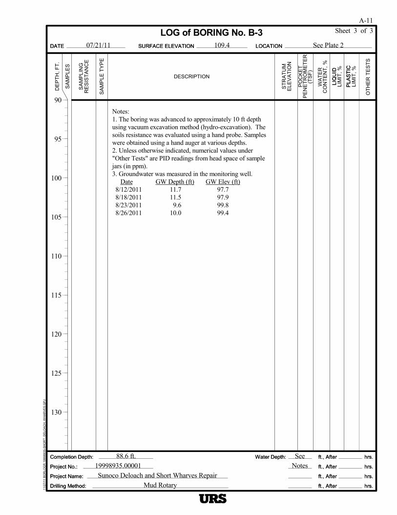
Notes:1. The boring was advanced to approximately 10 ft depthusing vacuum excavation method (hydro-excavation). Thesoils resistance was evaluated using a hand probe. Sampleswere obtained using a hand auger at various depths.2. Unless otherwise indicated, numerical values under"Other Tests" are PID readings from head space of samplejars (in ppm).3. Groundwater was measured in the monitoring well.
Date GW Depth (ft) GW Elev (ft) 8/12/2011 11.7 97.7 8/18/2011 11.5 97.9 8/23/2011 9.6 99.8 8/26/2011 10.0 99.4
LIQ
UID
LOCATIONDATE
ST
RA
TU
M
See Plate 2
Sheet 3 of 3
Drilling Method:
SA
MP
LES
ft., After
ft., After
ft., After
ft., After
Sunoco Deloach and Short Wharves Repair
LIM
IT,
%
hrs.
hrs.
hrs.
hrs.
109.4
19998935.0000188.6 ft.
PLA
ST
IC
SURFACE ELEVATION11
/27/
11 B
OR
LOG
R 1
9998
935
-SH
OR
T_D
ELO
AC
H_W
HA
RV
ES
.GP
J
LOG of BORING No. B-3
Water Depth:
Mud Rotary
ELE
VA
TIO
N
Completion Depth:
Project Name:
RE
SIS
TA
NC
E
SeeNotes
OT
HE
R T
ES
TS
07/21/11
90
95
100
105
110
115
120
125
130
LIM
IT,
%
Project No.:
DE
PT
H,
FT
.
A-11
Completion Depth:
DESCRIPTION
CO
NT
EN
T,
%
hrs.
hrs.
hrs.
hrs.
SURFACE ELEVATION
Water Depth:
PLA
ST
IC
Project No.:
SA
MP
LE T
YP
E
(TS
F)
ft., After
ft., After
ft., After
ft., After
PO
CK
ET
WA
TE
R
DATE
Drilling Method:
LIQ
UID
PE
NE
TR
OM
ET
ER
LOCATION
Project Name:
SA
MP
LIN
G

Top of Bulkhead
(Continue on Sheet 2 of 3)
LIQ
UID
LOCATIONDATE
ST
RA
TU
M
See Plate 2
Sheet 1 of 3
Drilling Method:
SA
MP
LES
ft., After
ft., After
ft., After
ft., After
Sunoco Deloach and Short Wharves Repair
LIM
IT,
%
hrs.
hrs.
hrs.
hrs.
104.0
19998935.0000187.2 ft.
PLA
ST
IC
SURFACE ELEVATION11
/27/
11 B
OR
LOG
R 1
9998
935
-SH
OR
T_D
ELO
AC
H_W
HA
RV
ES
.GP
J
LOG of BORING No. B-4
Water Depth:
Mud Rotary
ELE
VA
TIO
N
Completion Depth:
Project Name:
RE
SIS
TA
NC
E
SeeNotes
OT
HE
R T
ES
TS
07/29/11
0
5
10
15
20
25
30
35
40
LIM
IT,
%
Project No.:
DE
PT
H,
FT
.
A-12
Completion Depth:
DESCRIPTION
CO
NT
EN
T,
%
hrs.
hrs.
hrs.
hrs.
SURFACE ELEVATION
Water Depth:
PLA
ST
IC
Project No.:
SA
MP
LE T
YP
E
(TS
F)
ft., After
ft., After
ft., After
ft., After
PO
CK
ET
WA
TE
R
DATE
Drilling Method:
LIQ
UID
PE
NE
TR
OM
ET
ER
LOCATION
Project Name:
SA
MP
LIN
G
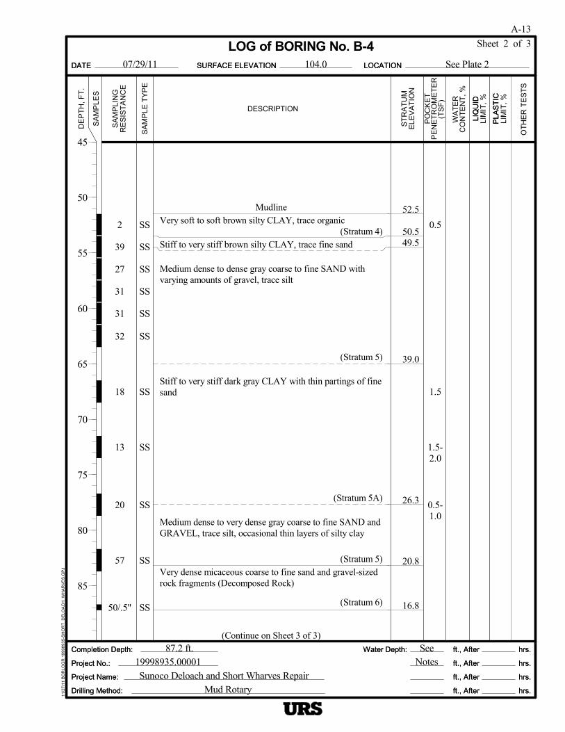
2
39
27
31
31
32
18
13
20
57
50/.5"
SS
SS
SS
SS
SS
SS
SS
SS
SS
SS
SS
0.5
1.5
1.5-2.0
0.5-1.0
52.5
50.549.5
39.0
26.3
20.8
16.8
MudlineVery soft to soft brown silty CLAY, trace organic
(Stratum 4)Stiff to very stiff brown silty CLAY, trace fine sand
Medium dense to dense gray coarse to fine SAND withvarying amounts of gravel, trace silt
(Stratum 5)
Stiff to very stiff dark gray CLAY with thin partings of finesand
(Stratum 5A)
Medium dense to very dense gray coarse to fine SAND andGRAVEL, trace silt, occasional thin layers of silty clay
(Stratum 5)Very dense micaceous coarse to fine sand and gravel-sizedrock fragments (Decomposed Rock)
(Stratum 6)
(Continue on Sheet 3 of 3)
LIQ
UID
LOCATIONDATE
ST
RA
TU
M
See Plate 2
Sheet 2 of 3
Drilling Method:
SA
MP
LES
ft., After
ft., After
ft., After
ft., After
Sunoco Deloach and Short Wharves Repair
LIM
IT,
%
hrs.
hrs.
hrs.
hrs.
104.0
19998935.0000187.2 ft.
PLA
ST
IC
SURFACE ELEVATION11
/27/
11 B
OR
LOG
R 1
9998
935
-SH
OR
T_D
ELO
AC
H_W
HA
RV
ES
.GP
J
LOG of BORING No. B-4
Water Depth:
Mud Rotary
ELE
VA
TIO
N
Completion Depth:
Project Name:
RE
SIS
TA
NC
E
SeeNotes
OT
HE
R T
ES
TS
07/29/11
45
50
55
60
65
70
75
80
85
LIM
IT,
%
Project No.:
DE
PT
H,
FT
.
A-13
Completion Depth:
DESCRIPTION
CO
NT
EN
T,
%
hrs.
hrs.
hrs.
hrs.
SURFACE ELEVATION
Water Depth:
PLA
ST
IC
Project No.:
SA
MP
LE T
YP
E
(TS
F)
ft., After
ft., After
ft., After
ft., After
PO
CK
ET
WA
TE
R
DATE
Drilling Method:
LIQ
UID
PE
NE
TR
OM
ET
ER
LOCATION
Project Name:
SA
MP
LIN
G

Notes:1. The drilling began at approximately 51.5 ft below the topof the bulkhead. All depths indicated in this log are fromthe top of the bulkhead.2. Drilling resistance (i.e., rig chatter) was encountered atapproximately 83 ft depth.3. Unless otherwise indicated, numerical values under"Other Tests" are PID readings from head space of samplejars (in ppm).
LIQ
UID
LOCATIONDATE
ST
RA
TU
M
See Plate 2
Sheet 3 of 3
Drilling Method:
SA
MP
LES
ft., After
ft., After
ft., After
ft., After
Sunoco Deloach and Short Wharves Repair
LIM
IT,
%
hrs.
hrs.
hrs.
hrs.
104.0
19998935.0000187.2 ft.
PLA
ST
IC
SURFACE ELEVATION11
/27/
11 B
OR
LOG
R 1
9998
935
-SH
OR
T_D
ELO
AC
H_W
HA
RV
ES
.GP
J
LOG of BORING No. B-4
Water Depth:
Mud Rotary
ELE
VA
TIO
N
Completion Depth:
Project Name:
RE
SIS
TA
NC
E
SeeNotes
OT
HE
R T
ES
TS
07/29/11
90
95
100
105
110
115
120
125
130
LIM
IT,
%
Project No.:
DE
PT
H,
FT
.
A-14
Completion Depth:
DESCRIPTION
CO
NT
EN
T,
%
hrs.
hrs.
hrs.
hrs.
SURFACE ELEVATION
Water Depth:
PLA
ST
IC
Project No.:
SA
MP
LE T
YP
E
(TS
F)
ft., After
ft., After
ft., After
ft., After
PO
CK
ET
WA
TE
R
DATE
Drilling Method:
LIQ
UID
PE
NE
TR
OM
ET
ER
LOCATION
Project Name:
SA
MP
LIN
G
31
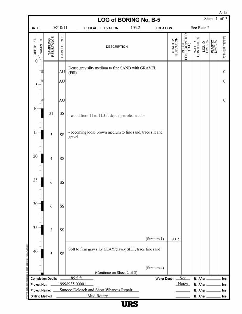
5
4
6
6
2
5
AU
AU
AU
SS
SS
SS
SS
SS
SS
SS
65.2
Dense gray silty medium to fine SAND with GRAVEL(Fill)
- wood from 11 to 11.5 ft depth, petroleum odor
- becoming loose brown medium to fine sand, trace silt andgravel
(Stratum 1)
Soft to firm gray silty CLAY/clayey SILT, trace fine sand
(Stratum 4)(Continue on Sheet 2 of 3)
0
0
0
LIQ
UID
LOCATIONDATE
ST
RA
TU
M
See Plate 2
Sheet 1 of 3
Drilling Method:
SA
MP
LES
ft., After
ft., After
ft., After
ft., After
Sunoco Deloach and Short Wharves Repair
LIM
IT,
%
hrs.
hrs.
hrs.
hrs.
103.2
19998935.0000185.5 ft.
PLA
ST
IC
SURFACE ELEVATION11
/27/
11 B
OR
LOG
R 1
9998
935
-SH
OR
T_D
ELO
AC
H_W
HA
RV
ES
.GP
J
LOG of BORING No. B-5
Water Depth:
Mud Rotary
ELE
VA
TIO
N
Completion Depth:
Project Name:
RE
SIS
TA
NC
E
SeeNotes
OT
HE
R T
ES
TS
08/10/11
0
5
10
15
20
25
30
35
40
LIM
IT,
%
Project No.:
DE
PT
H,
FT
.
A-15
Completion Depth:
DESCRIPTION
CO
NT
EN
T,
%
hrs.
hrs.
hrs.
hrs.
SURFACE ELEVATION
Water Depth:
PLA
ST
IC
Project No.:
SA
MP
LE T
YP
E
(TS
F)
ft., After
ft., After
ft., After
ft., After
PO
CK
ET
WA
TE
R
DATE
Drilling Method:
LIQ
UID
PE
NE
TR
OM
ET
ER
LOCATION
Project Name:
SA
MP
LIN
G

WOH
P
10
26
23
9
18
37
19
100/6"
2230
SS
P
SS
SS
S3
SS
SS
SS
SS
SS
0.5
2.5-3.0
1.5-1.75
1.5
1.75-2.5
53.7
50.2
45.2
35.2
32.2
30.2
20.2
18.217.7
32.8
Soft to firm gray silty CLAY, trace fine sand
(Stratum 4)Medium dense brown silty coarse to fine SAND, with thinlayers of silty clay
(Stratum 5)
Very stiff dark brown CLAY, trace fine sand
(Stratum 5A)
Medium dense brown coarse to fine SAND and GRAVEL,trace silt with thin layers of silty clay
- becoming loose medium to fine sand
(Stratum 5)Stiff to very stiff dark gray CLAY, trace fine sand
(Stratum 5A)Medium dense dark gray medium to fine SAND, trace silt
(Stratum 5)
Stiff to very stiff gray CLAY, trace fine sand with thinpartings of fine sand, and occasional thin layers of coarse tofine sand
(Stratum 5A)Very dense gray coarse to fine SAND and GRAVEL, tracesilt (Stratum 5)Very dense micaceous coarse to fine SAND andgravel-sized rock fragments (Decomposed Rock)
(Stratum 6)
M T
LIQ
UID
LOCATIONDATE
ST
RA
TU
M
See Plate 2
Sheet 2 of 3
Drilling Method:
SA
MP
LES
ft., After
ft., After
ft., After
ft., After
Sunoco Deloach and Short Wharves Repair
LIM
IT,
%
hrs.
hrs.
hrs.
hrs.
103.2
19998935.0000185.5 ft.
PLA
ST
IC
SURFACE ELEVATION11
/27/
11 B
OR
LOG
R 1
9998
935
-SH
OR
T_D
ELO
AC
H_W
HA
RV
ES
.GP
J
LOG of BORING No. B-5
Water Depth:
Mud Rotary
ELE
VA
TIO
N
Completion Depth:
Project Name:
RE
SIS
TA
NC
E
SeeNotes
OT
HE
R T
ES
TS
08/10/11
45
50
55
60
65
70
75
80
85
LIM
IT,
%
Project No.:
DE
PT
H,
FT
.
A-16
Completion Depth:
DESCRIPTION
CO
NT
EN
T,
%
hrs.
hrs.
hrs.
hrs.
SURFACE ELEVATION
Water Depth:
PLA
ST
IC
Project No.:
SA
MP
LE T
YP
E
(TS
F)
ft., After
ft., After
ft., After
ft., After
PO
CK
ET
WA
TE
R
DATE
Drilling Method:
LIQ
UID
PE
NE
TR
OM
ET
ER
LOCATION
Project Name:
SA
MP
LIN
G
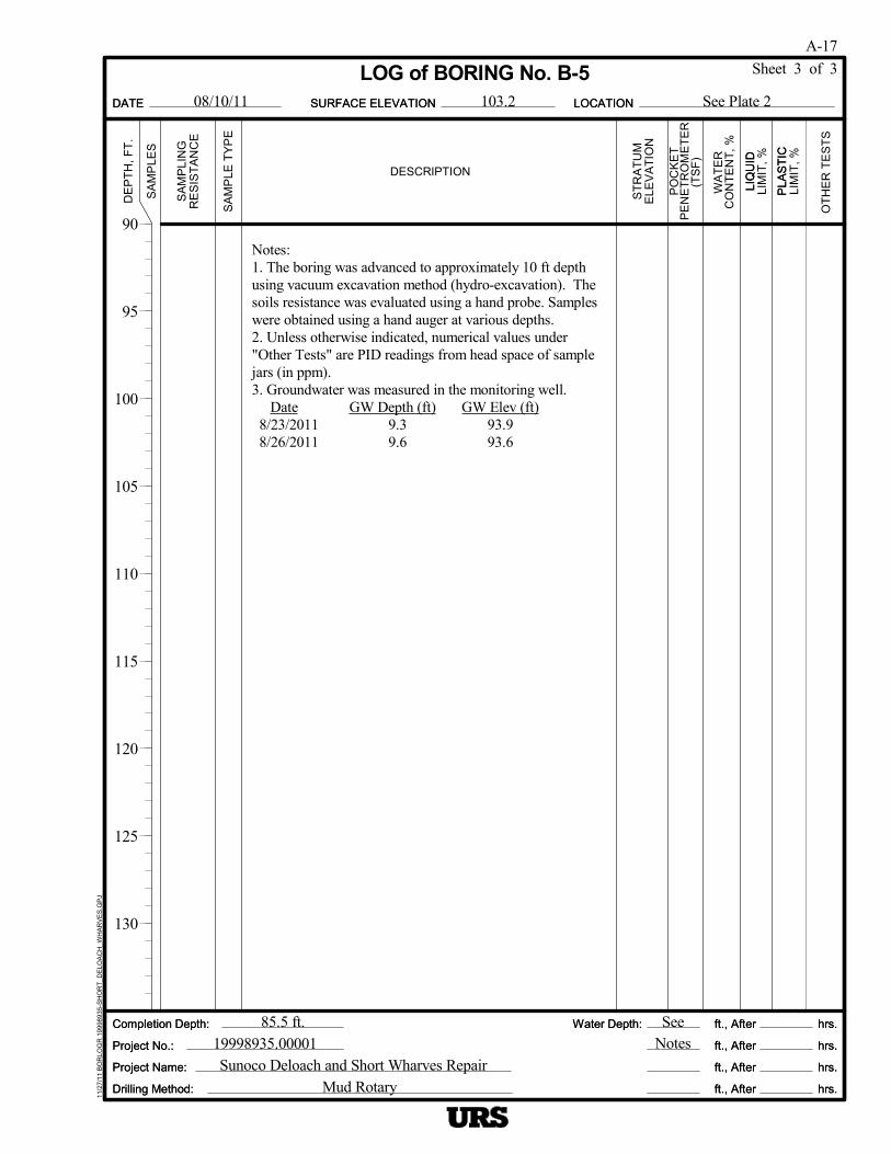
Notes:1. The boring was advanced to approximately 10 ft depthusing vacuum excavation method (hydro-excavation). Thesoils resistance was evaluated using a hand probe. Sampleswere obtained using a hand auger at various depths.2. Unless otherwise indicated, numerical values under"Other Tests" are PID readings from head space of samplejars (in ppm).3. Groundwater was measured in the monitoring well.
Date GW Depth (ft) GW Elev (ft) 8/23/2011 9.3 93.9 8/26/2011 9.6 93.6
LIQ
UID
LOCATIONDATE
ST
RA
TU
M
See Plate 2
Sheet 3 of 3
Drilling Method:
SA
MP
LES
ft., After
ft., After
ft., After
ft., After
Sunoco Deloach and Short Wharves Repair
LIM
IT,
%
hrs.
hrs.
hrs.
hrs.
103.2
19998935.0000185.5 ft.
PLA
ST
IC
SURFACE ELEVATION11
/27/
11 B
OR
LOG
R 1
9998
935
-SH
OR
T_D
ELO
AC
H_W
HA
RV
ES
.GP
J
LOG of BORING No. B-5
Water Depth:
Mud Rotary
ELE
VA
TIO
N
Completion Depth:
Project Name:
RE
SIS
TA
NC
E
SeeNotes
OT
HE
R T
ES
TS
08/10/11
90
95
100
105
110
115
120
125
130
LIM
IT,
%
Project No.:
DE
PT
H,
FT
.
A-17
Completion Depth:
DESCRIPTION
CO
NT
EN
T,
%
hrs.
hrs.
hrs.
hrs.
SURFACE ELEVATION
Water Depth:
PLA
ST
IC
Project No.:
SA
MP
LE T
YP
E
(TS
F)
ft., After
ft., After
ft., After
ft., After
PO
CK
ET
WA
TE
R
DATE
Drilling Method:
LIQ
UID
PE
NE
TR
OM
ET
ER
LOCATION
Project Name:
SA
MP
LIN
G

23
32
3
3
6
7
13
16
AUAU
AU
AU
SS
SS
SS
SS
SS
SS
SS
SS
0.5
0.5
0.5
0.5
94.6
91.1
83.1
64.6
Dense brown silty coarse to fine SAND and GRAVEL(Fill)
(Stratum 1)Firm to stiff dark gray sandy silty CLAY
(Stratum 2)
Medium dense to dense brown coarse to fine SAND andGRAVEL, trace silt
(Stratum 3)
Soft to firm gray silty CLAY/clayey SILT, trace fine sand
- fine sandy silt
- fine sandy silt
- clayey silt
(Stratum 4)
Medium dense brown medium to fine SAND, trace silt,occasional thin layers of silty clay
(Stratum 5)(Continue on Sheet 2 of 3)
300
400
800
LIQ
UID
LOCATIONDATE
ST
RA
TU
M
See Plate 2
Sheet 1 of 3
Drilling Method:
SA
MP
LES
ft., After
ft., After
ft., After
ft., After
Sunoco Deloach and Short Wharves Repair
LIM
IT,
%
hrs.
hrs.
hrs.
hrs.
101.1
19998935.0000183.3 ft.
PLA
ST
IC
SURFACE ELEVATION11
/27/
11 B
OR
LOG
R 1
9998
935
-SH
OR
T_D
ELO
AC
H_W
HA
RV
ES
.GP
J
LOG of BORING No. B-6
Water Depth:
Mud Rotary
ELE
VA
TIO
N
Completion Depth:
Project Name:
RE
SIS
TA
NC
E
SeeNotes
OT
HE
R T
ES
TS
06/27/11
0
5
10
15
20
25
30
35
40
LIM
IT,
%
Project No.:
DE
PT
H,
FT
.
A-18
Completion Depth:
DESCRIPTION
CO
NT
EN
T,
%
hrs.
hrs.
hrs.
hrs.
SURFACE ELEVATION
Water Depth:
PLA
ST
IC
Project No.:
SA
MP
LE T
YP
E
(TS
F)
ft., After
ft., After
ft., After
ft., After
PO
CK
ET
WA
TE
R
DATE
Drilling Method:
LIQ
UID
PE
NE
TR
OM
ET
ER
LOCATION
Project Name:
SA
MP
LIN
G

22
30
60
37
27
11
26
100/3"
SS
SS
SS
SS
SS
SS
SS
SS
34.6
20.1
17.8
Medium dense brown medium to fine SAND, trace silt,occasional thin layers of silty clay
(Stratum 5)- becoming dense to very dense gray coarse to fine sandwith variable amounts of gravel, trace silt
- becoming medium to fine sand
(Stratum 5)
Very stiff dark gray CLAY with thin partings of fine sand
(Stratum 5A)Very dense micaceous coarse to fine SAND andgravel-sized rock fragments (Decomposed Rock)
(Stratum 6)
(Continue on Sheet 3 of 3)
LIQ
UID
LOCATIONDATE
ST
RA
TU
M
See Plate 2
Sheet 2 of 3
Drilling Method:
SA
MP
LES
ft., After
ft., After
ft., After
ft., After
Sunoco Deloach and Short Wharves Repair
LIM
IT,
%
hrs.
hrs.
hrs.
hrs.
101.1
19998935.0000183.3 ft.
PLA
ST
IC
SURFACE ELEVATION11
/27/
11 B
OR
LOG
R 1
9998
935
-SH
OR
T_D
ELO
AC
H_W
HA
RV
ES
.GP
J
LOG of BORING No. B-6
Water Depth:
Mud Rotary
ELE
VA
TIO
N
Completion Depth:
Project Name:
RE
SIS
TA
NC
E
SeeNotes
OT
HE
R T
ES
TS
06/27/11
45
50
55
60
65
70
75
80
85
LIM
IT,
%
Project No.:
DE
PT
H,
FT
.
A-19
Completion Depth:
DESCRIPTION
CO
NT
EN
T,
%
hrs.
hrs.
hrs.
hrs.
SURFACE ELEVATION
Water Depth:
PLA
ST
IC
Project No.:
SA
MP
LE T
YP
E
(TS
F)
ft., After
ft., After
ft., After
ft., After
PO
CK
ET
WA
TE
R
DATE
Drilling Method:
LIQ
UID
PE
NE
TR
OM
ET
ER
LOCATION
Project Name:
SA
MP
LIN
G
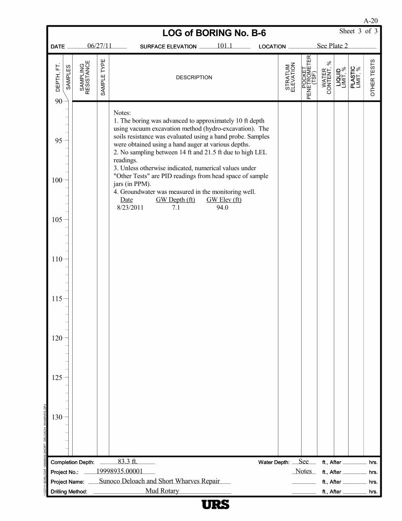
Notes:1. The boring was advanced to approximately 10 ft depthusing vacuum excavation method (hydro-excavation). Thesoils resistance was evaluated using a hand probe. Sampleswere obtained using a hand auger at various depths.2. No sampling between 14 ft and 21.5 ft due to high LELreadings.3. Unless otherwise indicated, numerical values under"Other Tests" are PID readings from head space of samplejars (in PPM).4. Groundwater was measured in the monitoring well.
Date GW Depth (ft) GW Elev (ft) 8/23/2011 7.1 94.0
LIQ
UID
LOCATIONDATE
ST
RA
TU
M
See Plate 2
Sheet 3 of 3
Drilling Method:
SA
MP
LES
ft., After
ft., After
ft., After
ft., After
Sunoco Deloach and Short Wharves Repair
LIM
IT,
%
hrs.
hrs.
hrs.
hrs.
101.1
19998935.0000183.3 ft.
PLA
ST
IC
SURFACE ELEVATION11
/27/
11 B
OR
LOG
R 1
9998
935
-SH
OR
T_D
ELO
AC
H_W
HA
RV
ES
.GP
J
LOG of BORING No. B-6
Water Depth:
Mud Rotary
ELE
VA
TIO
N
Completion Depth:
Project Name:
RE
SIS
TA
NC
E
SeeNotes
OT
HE
R T
ES
TS
06/27/11
90
95
100
105
110
115
120
125
130
LIM
IT,
%
Project No.:
DE
PT
H,
FT
.
A-20
Completion Depth:
DESCRIPTION
CO
NT
EN
T,
%
hrs.
hrs.
hrs.
hrs.
SURFACE ELEVATION
Water Depth:
PLA
ST
IC
Project No.:
SA
MP
LE T
YP
E
(TS
F)
ft., After
ft., After
ft., After
ft., After
PO
CK
ET
WA
TE
R
DATE
Drilling Method:
LIQ
UID
PE
NE
TR
OM
ET
ER
LOCATION
Project Name:
SA
MP
LIN
G

Top of Bulkhead
(Continue on Sheet 2 of 3)
LIQ
UID
LOCATIONDATE
ST
RA
TU
M
See Plate 2
Sheet 1 of 3
Drilling Method:
SA
MP
LES
ft., After
ft., After
ft., After
ft., After
Sunoco Deloach and Short Wharves Repair
LIM
IT,
%
hrs.
hrs.
hrs.
hrs.
109.8
19998935.0000184.0 ft.
PLA
ST
IC
SURFACE ELEVATION11
/27/
11 B
OR
LOG
R 1
9998
935
-SH
OR
T_D
ELO
AC
H_W
HA
RV
ES
.GP
J
LOG of BORING No. B-7
Water Depth:
Mud Rotary
ELE
VA
TIO
N
Completion Depth:
Project Name:
RE
SIS
TA
NC
E
SeeNotes
OT
HE
R T
ES
TS
07/27/11
0
5
10
15
20
25
30
35
40
LIM
IT,
%
Project No.:
DE
PT
H,
FT
.
A-21
Completion Depth:
DESCRIPTION
CO
NT
EN
T,
%
hrs.
hrs.
hrs.
hrs.
SURFACE ELEVATION
Water Depth:
PLA
ST
IC
Project No.:
SA
MP
LE T
YP
E
(TS
F)
ft., After
ft., After
ft., After
ft., After
PO
CK
ET
WA
TE
R
DATE
Drilling Method:
LIQ
UID
PE
NE
TR
OM
ET
ER
LOCATION
Project Name:
SA
MP
LIN
G

41
43
35
65
13
36
36
38
18
68
25
20
62
53
SS
SS
SS
SS
SS
SS
SS
SS
SS
SS
1.75-2.0
57.4
43.8
41.3
33.8
28.8
26.325.8
7.4
11.2
11.8
15.6
10.5
39.0
12.2
27.8
11.7
Mudline
Dense brown silty coarse to fine SAND and GRAVEL
- becoming dense coarse to fine sand, trace silt, gravel
- medium dense
(Stratum 5)Very stiff dark gray CLAY with thin partings of fine sand
(Stratum 5A)
Dense gray coarse to fine SAND, trace silt, gravel
- sand and gravel
(Stratum 5)
Stiff to very stiff gray clay with thin layers of fine sand
(Stratum 5A)Very dense SAND and GRAVEL
(Stratum 5)Very dense micaceous coarse to fine sand and gravel-sizedrock fragments (Decomposed Rock) (Stratum 6)
(Continue on Sheet 3 of 3)
M
M
M
M
M
M
M
M
M
LIQ
UID
LOCATIONDATE
ST
RA
TU
M
See Plate 2
Sheet 2 of 3
Drilling Method:
SA
MP
LES
ft., After
ft., After
ft., After
ft., After
Sunoco Deloach and Short Wharves Repair
LIM
IT,
%
hrs.
hrs.
hrs.
hrs.
109.8
19998935.0000184.0 ft.
PLA
ST
IC
SURFACE ELEVATION11
/27/
11 B
OR
LOG
R 1
9998
935
-SH
OR
T_D
ELO
AC
H_W
HA
RV
ES
.GP
J
LOG of BORING No. B-7
Water Depth:
Mud Rotary
ELE
VA
TIO
N
Completion Depth:
Project Name:
RE
SIS
TA
NC
E
SeeNotes
OT
HE
R T
ES
TS
07/27/11
45
50
55
60
65
70
75
80
85
LIM
IT,
%
Project No.:
DE
PT
H,
FT
.
A-22
Completion Depth:
DESCRIPTION
CO
NT
EN
T,
%
hrs.
hrs.
hrs.
hrs.
SURFACE ELEVATION
Water Depth:
PLA
ST
IC
Project No.:
SA
MP
LE T
YP
E
(TS
F)
ft., After
ft., After
ft., After
ft., After
PO
CK
ET
WA
TE
R
DATE
Drilling Method:
LIQ
UID
PE
NE
TR
OM
ET
ER
LOCATION
Project Name:
SA
MP
LIN
G

Notes:1. The drilling began at approximately 52.4 ft below the topof the bulkhead. All depths indicated in this log are fromthe top of the bulkhead.2. Loss of drilling fluid noted at approximatley 61 ft and 81ft depths.
LIQ
UID
LOCATIONDATE
ST
RA
TU
M
See Plate 2
Sheet 3 of 3
Drilling Method:
SA
MP
LES
ft., After
ft., After
ft., After
ft., After
Sunoco Deloach and Short Wharves Repair
LIM
IT,
%
hrs.
hrs.
hrs.
hrs.
109.8
19998935.0000184.0 ft.
PLA
ST
IC
SURFACE ELEVATION11
/27/
11 B
OR
LOG
R 1
9998
935
-SH
OR
T_D
ELO
AC
H_W
HA
RV
ES
.GP
J
LOG of BORING No. B-7
Water Depth:
Mud Rotary
ELE
VA
TIO
N
Completion Depth:
Project Name:
RE
SIS
TA
NC
E
SeeNotes
OT
HE
R T
ES
TS
07/27/11
90
95
100
105
110
115
120
125
130
LIM
IT,
%
Project No.:
DE
PT
H,
FT
.
A-23
Completion Depth:
DESCRIPTION
CO
NT
EN
T,
%
hrs.
hrs.
hrs.
hrs.
SURFACE ELEVATION
Water Depth:
PLA
ST
IC
Project No.:
SA
MP
LE T
YP
E
(TS
F)
ft., After
ft., After
ft., After
ft., After
PO
CK
ET
WA
TE
R
DATE
Drilling Method:
LIQ
UID
PE
NE
TR
OM
ET
ER
LOCATION
Project Name:
SA
MP
LIN
G

4
4
5
6
4
30
52
35
AU
AU
AU
SS
SS
SS
SS
SS
SS
SS
SS
20.8
27.8
14.1
Dense brown silty coarse to fine SAND and GRAVEL(Fill)- brown silty coarse to fine sand
- medium dense sand and gravel
- becoming loose silty fine sand
- trace clay
- approximately 6" of wood
- concrete and brick fragments
- concrete and brick fragments
(Stratum 1)(Continue on Sheet 2 of 3)
1000
1000
3000
M
M
M
LIQ
UID
LOCATIONDATE
ST
RA
TU
M
See Plate 2
Sheet 1 of 3
Drilling Method:
SA
MP
LES
ft., After
ft., After
ft., After
ft., After
Sunoco Deloach and Short Wharves Repair
LIM
IT,
%
hrs.
hrs.
hrs.
hrs.
109.8
19998935.0000184.2 ft.
PLA
ST
IC
SURFACE ELEVATION11
/27/
11 B
OR
LOG
R 1
9998
935
-SH
OR
T_D
ELO
AC
H_W
HA
RV
ES
.GP
J
LOG of BORING No. B-8
Water Depth:
Mud Rotary
ELE
VA
TIO
N
Completion Depth:
Project Name:
RE
SIS
TA
NC
E
SeeNotes
OT
HE
R T
ES
TS
06/27/11
0
5
10
15
20
25
30
35
40
LIM
IT,
%
Project No.:
DE
PT
H,
FT
.
A-24
Completion Depth:
DESCRIPTION
CO
NT
EN
T,
%
hrs.
hrs.
hrs.
hrs.
SURFACE ELEVATION
Water Depth:
PLA
ST
IC
Project No.:
SA
MP
LE T
YP
E
(TS
F)
ft., After
ft., After
ft., After
ft., After
PO
CK
ET
WA
TE
R
DATE
Drilling Method:
LIQ
UID
PE
NE
TR
OM
ET
ER
LOCATION
Project Name:
SA
MP
LIN
G
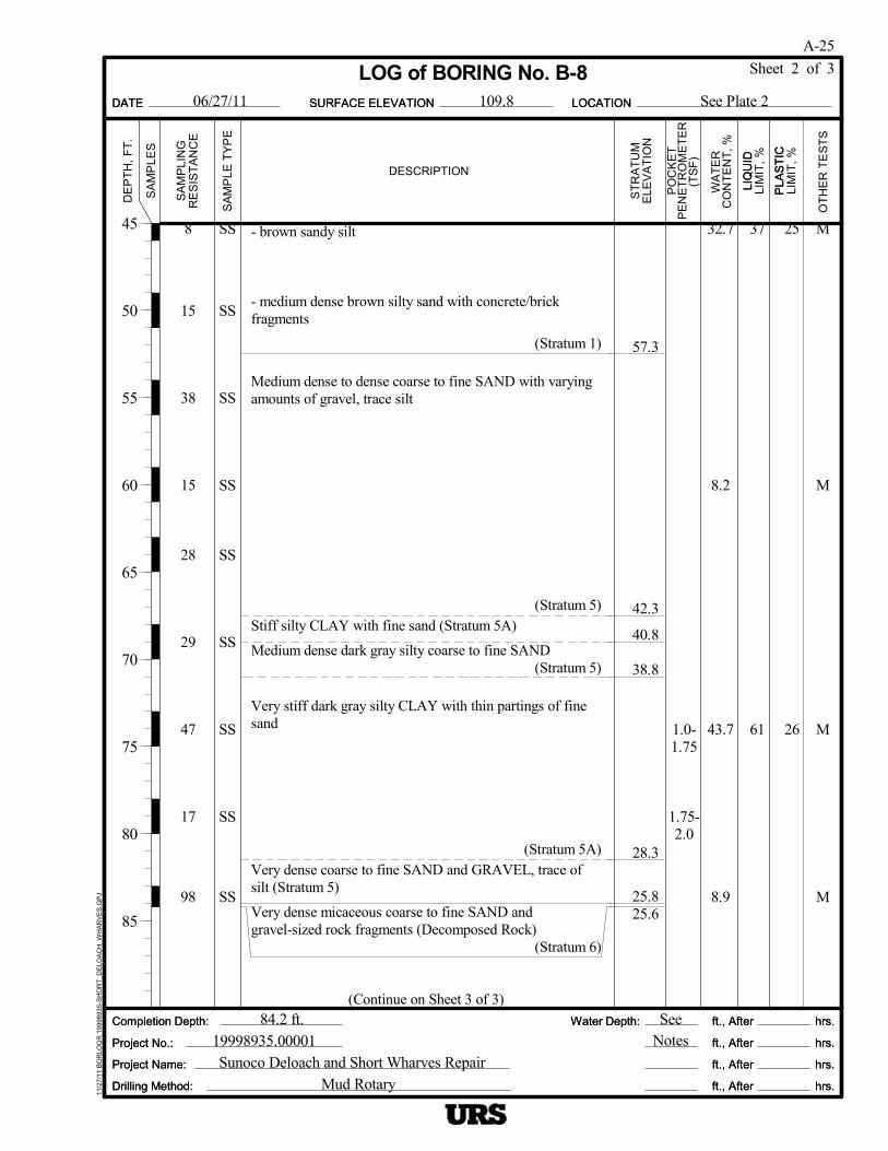
8
15
38
15
28
29
47
17
98
25
26
37
61
SS
SS
SS
SS
SS
SS
SS
SS
SS
1.0-1.75
1.75-2.0
57.3
42.3
40.8
38.8
28.3
25.825.6
32.7
8.2
43.7
8.9
- brown sandy silt
- medium dense brown silty sand with concrete/brickfragments
(Stratum 1)
Medium dense to dense coarse to fine SAND with varyingamounts of gravel, trace silt
(Stratum 5)Stiff silty CLAY with fine sand (Stratum 5A)
Medium dense dark gray silty coarse to fine SAND(Stratum 5)
Very stiff dark gray silty CLAY with thin partings of finesand
(Stratum 5A)Very dense coarse to fine SAND and GRAVEL, trace ofsilt (Stratum 5)
Very dense micaceous coarse to fine SAND andgravel-sized rock fragments (Decomposed Rock)
(Stratum 6)
(Continue on Sheet 3 of 3)
M
M
M
M
LIQ
UID
LOCATIONDATE
ST
RA
TU
M
See Plate 2
Sheet 2 of 3
Drilling Method:
SA
MP
LES
ft., After
ft., After
ft., After
ft., After
Sunoco Deloach and Short Wharves Repair
LIM
IT,
%
hrs.
hrs.
hrs.
hrs.
109.8
19998935.0000184.2 ft.
PLA
ST
IC
SURFACE ELEVATION11
/27/
11 B
OR
LOG
R 1
9998
935
-SH
OR
T_D
ELO
AC
H_W
HA
RV
ES
.GP
J
LOG of BORING No. B-8
Water Depth:
Mud Rotary
ELE
VA
TIO
N
Completion Depth:
Project Name:
RE
SIS
TA
NC
E
SeeNotes
OT
HE
R T
ES
TS
06/27/11
45
50
55
60
65
70
75
80
85
LIM
IT,
%
Project No.:
DE
PT
H,
FT
.
A-25
Completion Depth:
DESCRIPTION
CO
NT
EN
T,
%
hrs.
hrs.
hrs.
hrs.
SURFACE ELEVATION
Water Depth:
PLA
ST
IC
Project No.:
SA
MP
LE T
YP
E
(TS
F)
ft., After
ft., After
ft., After
ft., After
PO
CK
ET
WA
TE
R
DATE
Drilling Method:
LIQ
UID
PE
NE
TR
OM
ET
ER
LOCATION
Project Name:
SA
MP
LIN
G

Notes:1. The boring was advanced to approximately 10 ft depthusing vacuum excavation method (hydro-excavation). Thesoils resistance was evaluated using a hand probe. Sampleswere obtained using a hand auger at various depths.2. Unless otherwise indicated, numerical values under"Other Tests" are PID readings from head space of samplejars (in ppm).3. Drilling resistance (i.e., rig chatter) was encountered atapproximately 36 ft and 41.5 ft depth.4. Groundwater was measured in the monitoring well.
Date GW Depth (ft) GW Elev (ft) 8/18/2011 9.3 100.5 8/23/2011 9.3 100.5 8/26/2011 9.8 100.0
LIQ
UID
LOCATIONDATE
ST
RA
TU
M
See Plate 2
Sheet 3 of 3
Drilling Method:
SA
MP
LES
ft., After
ft., After
ft., After
ft., After
Sunoco Deloach and Short Wharves Repair
LIM
IT,
%
hrs.
hrs.
hrs.
hrs.
109.8
19998935.0000184.2 ft.
PLA
ST
IC
SURFACE ELEVATION11
/27/
11 B
OR
LOG
R 1
9998
935
-SH
OR
T_D
ELO
AC
H_W
HA
RV
ES
.GP
J
LOG of BORING No. B-8
Water Depth:
Mud Rotary
ELE
VA
TIO
N
Completion Depth:
Project Name:
RE
SIS
TA
NC
E
SeeNotes
OT
HE
R T
ES
TS
06/27/11
90
95
100
105
110
115
120
125
130
LIM
IT,
%
Project No.:
DE
PT
H,
FT
.
A-26
Completion Depth:
DESCRIPTION
CO
NT
EN
T,
%
hrs.
hrs.
hrs.
hrs.
SURFACE ELEVATION
Water Depth:
PLA
ST
IC
Project No.:
SA
MP
LE T
YP
E
(TS
F)
ft., After
ft., After
ft., After
ft., After
PO
CK
ET
WA
TE
R
DATE
Drilling Method:
LIQ
UID
PE
NE
TR
OM
ET
ER
LOCATION
Project Name:
SA
MP
LIN
G

2
.P.
30
8
P
11
11
20
18
15
27
22
24
46
28
AU
AU
AU
AU
AUAUSS
.P.
SS
SS
P
SS
SS
SS
SS
1.5-1.75
0.75-1.0
0.75-1.0
109.5
97.5
92.5
72.0
24.3
36.8
33.7
22.6
Dense brown silty coarse to fine SAND and GRAVEL(Fill)
(Stratum 1)
Firm to stiff dark gray sandy silty CLAY
(Stratum 2)
Medium dense to dense brown silty SAND and GRAVEL
(Stratum 3)
Firm to stiff gray silty CLAY
- becoming sandy silty CLAY
(Stratum 4)Medium dense to dense brown silty coarse to fine SAND
(Continue on Sheet 2 of 3)
450
20
400
340
420400
M
M
M
M T C
M
M
LIQ
UID
LOCATIONDATE
ST
RA
TU
M
See Plate 2
Sheet 1 of 3
Drilling Method:
SA
MP
LES
ft., After
ft., After
ft., After
ft., After
Sunoco Deloach and Short Wharves Repair
LIM
IT,
%
hrs.
hrs.
hrs.
hrs.
114.0
19998935.0000198.1 ft.
PLA
ST
IC
SURFACE ELEVATION11
/27/
11 B
OR
LOG
R 1
9998
935
-SH
OR
T_D
ELO
AC
H_W
HA
RV
ES
.GP
J
LOG of BORING No. B-9
Water Depth:
Mud Rotary
ELE
VA
TIO
N
Completion Depth:
Project Name:
RE
SIS
TA
NC
E
SeeNotes
OT
HE
R T
ES
TS
07/19/11
0
5
10
15
20
25
30
35
40
LIM
IT,
%
Project No.:
DE
PT
H,
FT
.
A-27
Completion Depth:
DESCRIPTION
CO
NT
EN
T,
%
hrs.
hrs.
hrs.
hrs.
SURFACE ELEVATION
Water Depth:
PLA
ST
IC
Project No.:
SA
MP
LE T
YP
E
(TS
F)
ft., After
ft., After
ft., After
ft., After
PO
CK
ET
WA
TE
R
DATE
Drilling Method:
LIQ
UID
PE
NE
TR
OM
ET
ER
LOCATION
Project Name:
SA
MP
LIN
G

11
16
53
28
15
31
23
42
20
NP
56
NP
SS
SS
SS
SS
SS
SS
SS
SS
1.0-1.25
1.75-2.0
47.0
37.0
27.0
8.6
3.6
35.6
9.1
Medium dense to dense brown silty coarse to fine SAND
- becoming medium dense to dense sand and gravel, tracesilt
(Stratum 5)
Stiff to very stiff gray CLAY with thin partings of fine sand
(Stratum 5A)
Medium dense to dense gray coarse to fine SAND andGRAVEL
(Stratum 5)Very dense micaceous brown coarse to fine SAND andgravel-sized rock fragments (Decomposed Rock)
(Continue on Sheet 3 of 3)
M
M
M
MLI
QU
ID
LOCATIONDATE
ST
RA
TU
M
See Plate 2
Sheet 2 of 3
Drilling Method:
SA
MP
LES
ft., After
ft., After
ft., After
ft., After
Sunoco Deloach and Short Wharves Repair
LIM
IT,
%
hrs.
hrs.
hrs.
hrs.
114.0
19998935.0000198.1 ft.
PLA
ST
IC
SURFACE ELEVATION11
/27/
11 B
OR
LOG
R 1
9998
935
-SH
OR
T_D
ELO
AC
H_W
HA
RV
ES
.GP
J
LOG of BORING No. B-9
Water Depth:
Mud Rotary
ELE
VA
TIO
N
Completion Depth:
Project Name:
RE
SIS
TA
NC
E
SeeNotes
OT
HE
R T
ES
TS
07/19/11
45
50
55
60
65
70
75
80
85
LIM
IT,
%
Project No.:
DE
PT
H,
FT
.
A-28
Completion Depth:
DESCRIPTION
CO
NT
EN
T,
%
hrs.
hrs.
hrs.
hrs.
SURFACE ELEVATION
Water Depth:
PLA
ST
IC
Project No.:
SA
MP
LE T
YP
E
(TS
F)
ft., After
ft., After
ft., After
ft., After
PO
CK
ET
WA
TE
R
DATE
Drilling Method:
LIQ
UID
PE
NE
TR
OM
ET
ER
LOCATION
Project Name:
SA
MP
LIN
G

100/4"
50/1"
NQ 52
SS
SS
NQ
21.0
15.9
5.7Very dense micaceous brown coarse to fine sand andgravel-sized rock fragments. (Decomposed Rock)
(Stratum 6)Medium hard to soft, coarse-grained, moderately to highlyweathered Mica Schist, laminations approximately 30degrees from horizontal, fractures along laminations
(Stratum 7)
Notes:1. The boring was advanced to approximately 10 ft depthusing vacuum excavation method (hydro-excavation). Thesoils resistance was evaluated using a hand probe. Sampleswere obtained using a hand auger at various depths.2. Unless otherwise indicated, numerical values under"Other Tests" are PID readings from head space of samplejars (in ppm).3. Groundwater was measured in the monitoring well.
Date GW Depth (ft) GW Elev (ft) 8/12/2011 10.5 103.5 8/18/2011 10.3 103.7 8/23/2011 10.7 103.3 8/26/2011 10.5 103.5
M
RQD 13
LIQ
UID
LOCATIONDATE
ST
RA
TU
M
See Plate 2
Sheet 3 of 3
Drilling Method:
SA
MP
LES
ft., After
ft., After
ft., After
ft., After
Sunoco Deloach and Short Wharves Repair
LIM
IT,
%
hrs.
hrs.
hrs.
hrs.
114.0
19998935.0000198.1 ft.
PLA
ST
IC
SURFACE ELEVATION11
/27/
11 B
OR
LOG
R 1
9998
935
-SH
OR
T_D
ELO
AC
H_W
HA
RV
ES
.GP
J
LOG of BORING No. B-9
Water Depth:
Mud Rotary
ELE
VA
TIO
N
Completion Depth:
Project Name:
RE
SIS
TA
NC
E
SeeNotes
OT
HE
R T
ES
TS
07/19/11
90
95
100
105
110
115
120
125
130
LIM
IT,
%
Project No.:
DE
PT
H,
FT
.
A-29
Completion Depth:
DESCRIPTION
CO
NT
EN
T,
%
hrs.
hrs.
hrs.
hrs.
SURFACE ELEVATION
Water Depth:
PLA
ST
IC
Project No.:
SA
MP
LE T
YP
E
(TS
F)
ft., After
ft., After
ft., After
ft., After
PO
CK
ET
WA
TE
R
DATE
Drilling Method:
LIQ
UID
PE
NE
TR
OM
ET
ER
LOCATION
Project Name:
SA
MP
LIN
G

Appendix B
Laboratory Testing

Appendix B
Laboratory Testing
B-1
Physical property tests were conducted in the laboratory on selected representative soil samples
to aid in classification and for correlation with engineering behavior of the soils. These tests
included natural water content (ASTM D 2216), liquid and plastic limits (ASTM D 4318), grain
size distribution (ASTM D 422). Three unconsolidated-undrained (UU) triaxial compression
tests (ASTM D 2850) and two consolidation tests (ASTM D 2435) were performed on relatively
undisturbed Shelby tube samples. One sample was tested for corrosivity evaluation, including pH,
resistivity, chlorides, and sulfates.
The numerical results are summarized on Pages B-2 and B-3 and are also shown on the
appropriate boring logs. Grain size distribution curves are shown on Pages B-4 through B-14.
UU triaxial test results are presented on Pages B-15 through B-17, and consolidation test results
on Pages B-18 and B-19.

B-3
ST-126.0-28.0 Gray SANDY LEAN CLAY CL 26.3 42 25 62 10
B-3
ST-126.0-28.0 31.1 90.9 *
B-3
ST-126.0-28.0 27.3 98.1 *
B-5
ST-147.5-49.5 Brown LEAN CLAY with SAND CL 32.8 88.0 30 22 84 19 *
B-7
S-152.4-54.4 Brown SILTY GRAVEL with SAND GM 7.4 15
B-7
S-254.4-56.4 Brown SILTY SAND with GRAVEL SM 11.2 21
B-7
S-458.1-60.1 Gray POORLY GRADED SAND with
SILTSP-SM 11.8 6
B-7
S-560.2-62.2 Gray POORLY GRADED SAND SP 15.6 5
B-7
S-662.2-64.2 Gray POORLY GRADED SAND with
GRAVELSP 10.5 5
B-7
S-7A67.5-68.5 Gray FAT CLAY CH 39.0 62 25 97
B-7
S-7B68.5-69.5 Gray POORLY GRADED SAND with
SILTSP-SM 15.4 5
B-7
S-872.5-74.5 Gray POORLY GRADED SAND with
SILT and GRAVELSP-SM 12.2 8
B-7
S-977.5-79.5 Gray CLAYEY SAND SC 27.8 53 20 35
B-7
S-10A82.5-83.5 Gray POORLY GRADED SAND with
SILT and GRAVELSP-SM 11.7 5
B-7
S-10B83.5-84.5 Gray WELL-GRADED SAND SW 10.3 4
B-8
S-1&S-210.0-14.0 20.8 106.7 ND ND ND 8200 7.8
B-8
S-1&S-210.0-16.0 Brown gray SILTY SAND SM 24.0 19
B-8
S-424.0-26.0 Brown gray SILTY SAND SM 27.8 29
B-8
S-839.0-41.0 Gray WELL-GRADED GRAVEL with
SANDGW 14.1 0
Analytical Results(ppm)
pH
Res
istiv
ity(O
hm-c
m)Atterberg Limits
B-2
WaterContent
(%) Sulfide
Project: Sunoco: Deloach and Short Wharves
TriaxialCompression
Grain Size
UU
*
<2µ(%)
Sheet 1 of 2
SulfateLiquidLimit
SpecificGravity
Project No.: 19998935
SUMMARY OF LABORATORY TEST RESULTS
Dry UnitWeight
(pcf)
Note: The soil classification is based partially on visual classification unless both grain size and Atterberg limits are performed.
Boringand Sample
Number
Refer to Laboratory Test Curves
OrganicContent
(%)
Note: The soil classification is based partially on visual classification unless both grain size and Atterberg limits are performed.
ClassificationDepth(feet)
PlasticLimit
USCSSymbol <#200
(%)
Com
pact
ion
Con
solid
atio
n
UCChloride
LAB_SUMMARY_TABLE_ANALYTICAL_PH 19998935 NO.2011-08-10 SUNOCO DELOACH & SHORT WHARVES 8-16-2011.GPJ URS_BLUE.GDT 11/8/11

B-8
S-944.0-46.0 Brown SANDY SILT ML 32.7 37 25 51
B-8
S-1259.0-61.0 Gray POORLY GRADED GRAVEL with
SANDGP 8.2 2
B-8
S-15A73.0-73.3 Gray FAT CLAY CH 43.7 61 26 100
B-8
S-15B73.3-73.8 Gray POORLY GRADED SAND with
SILT and GRAVELSP-SM 8.5 NP NP 5
B-8
S-15C73.8-74.2 Gray FAT CLAY CH 37.4 66 26 96
B-8
S-17A83.0-85.0 Gray POORLY GRADED SAND with
GRAVELSP 8.9 4
B-9
S-111-13 Brown gray LEAN CLAY with SAND CL 24.3 24 15 75
B-9
S-217-19.5 Brown SILTY SAND with GRAVEL SM 8.9 14
B-9
S-323.4-25.4 Gray LEAN CLAY CL 36.8 46 27 96
B-9
ST-226.0-28.0 Gray SILTY CLAY CL-ML 33.7 28 22 93 14
B-9
ST-226.0-28.0 35.0 86.4 *
B-9
ST-226.0-28.0 26.8 96.8 *
B-9
S-533.5-35.5 Brown SANDY SILTY CLAY CL-ML 24.2 24 20 56
B-9
S-743.3-45.3 Brown WELL-GRADED SAND with SILT SW-SM 22.6 11
B-9
S-953.3-55.3 Brown WELL-GRADED GRAVEL with
SANDGW 8.6 3
B-9
S-1163.5-65.5 Brown POORLY GRADED GRAVEL GP 3.6 0
B-9
S-1268.5-70.5 Gray FAT CLAY CH 35.6 56 20 100
B-9
S-1478.5-80.5 Gray POORLY GRADED GRAVEL with
SILT and SANDGP-GM 9.1 NP NP 7
B-9
S-1689-91 Gray WELL-GRADED GRAVEL with
SANDGW 5.7 4
Analytical Results(ppm)
pH
Res
istiv
ity(O
hm-c
m)Atterberg Limits
B-3
WaterContent
(%) Sulfide
Project: Sunoco: Deloach and Short Wharves
TriaxialCompression
Grain Size
UU
*
<2µ(%)
Sheet 2 of 2
SulfateLiquidLimit
SpecificGravity
Project No.: 19998935
SUMMARY OF LABORATORY TEST RESULTS
Dry UnitWeight
(pcf)
Note: The soil classification is based partially on visual classification unless both grain size and Atterberg limits are performed.
Boringand Sample
Number
Refer to Laboratory Test Curves
OrganicContent
(%)
Note: The soil classification is based partially on visual classification unless both grain size and Atterberg limits are performed.
ClassificationDepth(feet)
PlasticLimit
USCSSymbol <#200
(%)
Com
pact
ion
Con
solid
atio
n
UCChloride
LAB_SUMMARY_TABLE_ANALYTICAL_PH 19998935 NO.2011-08-10 SUNOCO DELOACH & SHORT WHARVES 8-16-2011.GPJ URS_BLUE.GDT 11/8/11
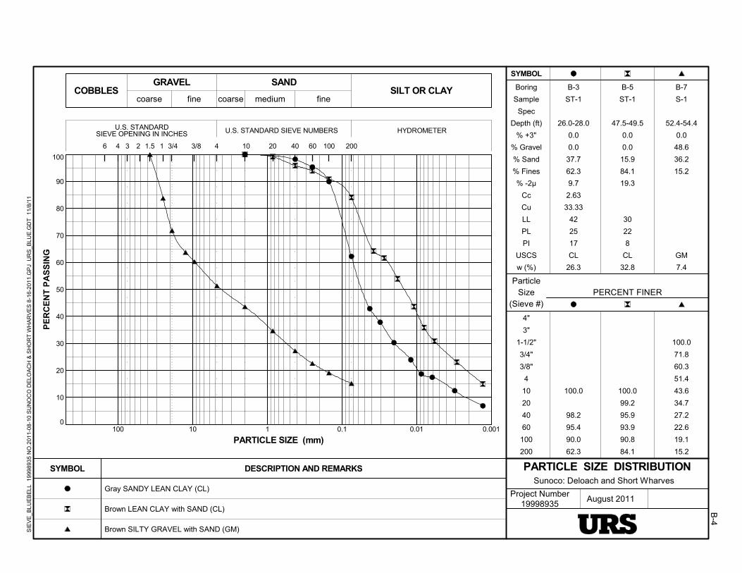
0
10
20
30
40
50
60
70
80
90
100
0.0010.010.1110100
4
4"
3"
1-1/2"
3/4"
3/8"
4
10
20
40
60
100
200
Project Number19998935
3
100.0
98.2
95.4
90.0
62.3
100.0
99.2
95.9
93.9
90.8
84.1
100.0
71.8
60.3
51.4
43.6
34.7
27.2
22.6
19.1
15.2
3/82
August 2011
10060
Sunoco: Deloach and Short Wharves
coarsecoarse fine medium fine
SIEVE OPENING IN INCHES U.S. STANDARD SIEVE NUMBERS HYDROMETER
SYMBOL
PE
RC
EN
T P
AS
SIN
G
PARTICLE SIZE (mm)
COBBLES
Gray SANDY LEAN CLAY (CL)
Brown LEAN CLAY with SAND (CL)
Brown SILTY GRAVEL with SAND (GM)
Boring
Sample
Spec
Depth (ft)
% +3"
% Gravel
% Sand
% Fines
% -2µ
Cc
Cu
LL
PL
PI
USCS
w (%)
6 3/4
DESCRIPTION AND REMARKS
ParticleSize
(Sieve #)
1
PARTICLE SIZE DISTRIBUTION
SAND
1.5 4010 200
GRAVEL
4
SILT OR CLAY
20
SYMBOL
PERCENT FINER
U.S. STANDARD
B-4
B-3
ST-1
26.0-28.0
0.0
0.0
37.7
62.3
9.7
2.63
33.33
42
25
17
CL
26.3
B-5
ST-1
47.5-49.5
0.0
0.0
15.9
84.1
19.3
30
22
8
CL
32.8
B-7
S-1
52.4-54.4
0.0
48.6
36.2
15.2
GM
7.4
SIE
VE
_BLU
EB
ELL
19
9989
35
NO
.201
1-0
8-10
SU
NO
CO
DE
LOA
CH
& S
HO
RT
WH
AR
VE
S 8
-16-
201
1.G
PJ
UR
S_B
LUE
.GD
T 1
1/8/
11

0
10
20
30
40
50
60
70
80
90
100
0.0010.010.1110100
4
4"
3"
1-1/2"
3/4"
3/8"
4
10
20
40
60
100
200
Project Number19998935
3
100.0
87.2
81.3
72.0
61.6
50.8
42.1
31.3
20.9
100.0
94.5
88.9
78.9
62.2
32.1
14.0
8.9
5.7
100.0
93.6
85.1
76.4
59.4
30.7
12.5
8.2
4.9
3/82
August 2011
10060
Sunoco: Deloach and Short Wharves
coarsecoarse fine medium fine
SIEVE OPENING IN INCHES U.S. STANDARD SIEVE NUMBERS HYDROMETER
SYMBOL
PE
RC
EN
T P
AS
SIN
G
PARTICLE SIZE (mm)
COBBLES
Brown SILTY SAND with GRAVEL (SM)
Gray POORLY GRADED SAND with SILT (SP-SM)
Gray POORLY GRADED SAND (SP)
Boring
Sample
Spec
Depth (ft)
% +3"
% Gravel
% Sand
% Fines
% -2µ
Cc
Cu
LL
PL
PI
USCS
w (%)
6 3/4
DESCRIPTION AND REMARKS
ParticleSize
(Sieve #)
1
PARTICLE SIZE DISTRIBUTION
SAND
1.5 4010 200
GRAVEL
4
SILT OR CLAY
20
SYMBOL
PERCENT FINER
U.S. STANDARD
B-5
B-7
S-2
54.4-56.4
0.0
18.7
60.4
20.9
SM
11.2
B-7
S-4
58.1-60.1
0.0
11.1
83.3
5.7
1.18
4.82
SP-SM
11.8
B-7
S-5
60.2-62.2
0.0
14.9
80.2
4.9
1.07
4.72
SP
15.6
SIE
VE
_BLU
EB
ELL
19
9989
35
NO
.201
1-0
8-10
SU
NO
CO
DE
LOA
CH
& S
HO
RT
WH
AR
VE
S 8
-16-
201
1.G
PJ
UR
S_B
LUE
.GD
T 1
1/8/
11

0
10
20
30
40
50
60
70
80
90
100
0.0010.010.1110100
4
4"
3"
1-1/2"
3/4"
3/8"
4
10
20
40
60
100
200
Project Number19998935
3
100.0
86.5
75.7
62.4
43.4
27.5
13.3
7.3
4.5
100.0
99.8
98.7
97.8
97.2
97.1
97.0
100.0
95.9
82.9
54.6
42.3
29.1
9.4
5.4
3/82
August 2011
10060
Sunoco: Deloach and Short Wharves
coarsecoarse fine medium fine
SIEVE OPENING IN INCHES U.S. STANDARD SIEVE NUMBERS HYDROMETER
SYMBOL
PE
RC
EN
T P
AS
SIN
G
PARTICLE SIZE (mm)
COBBLES
Gray POORLY GRADED SAND with GRAVEL (SP)
Gray FAT CLAY (CH)
Gray POORLY GRADED SAND with SILT (SP-SM)
Boring
Sample
Spec
Depth (ft)
% +3"
% Gravel
% Sand
% Fines
% -2µ
Cc
Cu
LL
PL
PI
USCS
w (%)
6 3/4
DESCRIPTION AND REMARKS
ParticleSize
(Sieve #)
1
PARTICLE SIZE DISTRIBUTION
SAND
1.5 4010 200
GRAVEL
4
SILT OR CLAY
20
SYMBOL
PERCENT FINER
U.S. STANDARD
B-6
B-7
S-6
62.2-64.2
0.0
24.3
71.2
4.5
0.66
9.47
SP
10.5
B-7
S-7A
67.5-68.5
0.0
0.0
3.0
97.0
62
25
37
CH
39.0
B-7
S-7B
68.5-69.5
0.0
4.1
90.5
5.4
0.44
6.57
SP-SM
15.4
SIE
VE
_BLU
EB
ELL
19
9989
35
NO
.201
1-0
8-10
SU
NO
CO
DE
LOA
CH
& S
HO
RT
WH
AR
VE
S 8
-16-
201
1.G
PJ
UR
S_B
LUE
.GD
T 1
1/8/
11

0
10
20
30
40
50
60
70
80
90
100
0.0010.010.1110100
4
4"
3"
1-1/2"
3/4"
3/8"
4
10
20
40
60
100
200
Project Number19998935
3
75.0
67.3
52.0
37.2
24.1
14.9
10.9
8.0
100.0
99.3
96.1
94.2
92.7
66.3
43.1
35.0
80.0
66.6
60.0
53.1
44.4
28.8
13.7
7.8
5.1
3/82
August 2011
10060
Sunoco: Deloach and Short Wharves
coarsecoarse fine medium fine
SIEVE OPENING IN INCHES U.S. STANDARD SIEVE NUMBERS HYDROMETER
SYMBOL
PE
RC
EN
T P
AS
SIN
G
PARTICLE SIZE (mm)
COBBLES
Gray POORLY GRADED SAND with SILT and GRAVEL (SP-SM)
Gray CLAYEY SAND (SC)
Gray POORLY GRADED SAND with SILT and GRAVEL (SP-SM)
Boring
Sample
Spec
Depth (ft)
% +3"
% Gravel
% Sand
% Fines
% -2µ
Cc
Cu
LL
PL
PI
USCS
w (%)
6 3/4
DESCRIPTION AND REMARKS
ParticleSize
(Sieve #)
1
PARTICLE SIZE DISTRIBUTION
SAND
1.5 4010 200
GRAVEL
4
SILT OR CLAY
20
SYMBOL
PERCENT FINER
U.S. STANDARD
B-7
B-7
S-8
72.5-74.5
0.0
32.7
59.3
8.0
0.89
26.15
SP-SM
12.2
B-7
S-9
77.5-79.5
0.0
0.7
64.2
35.0
53
20
33
SC
27.8
B-7
S-10A
82.5-83.5
0.0
40.0
54.9
5.1
0.23
26.26
SP-SM
11.7
SIE
VE
_BLU
EB
ELL
19
9989
35
NO
.201
1-0
8-10
SU
NO
CO
DE
LOA
CH
& S
HO
RT
WH
AR
VE
S 8
-16-
201
1.G
PJ
UR
S_B
LUE
.GD
T 1
1/8/
11
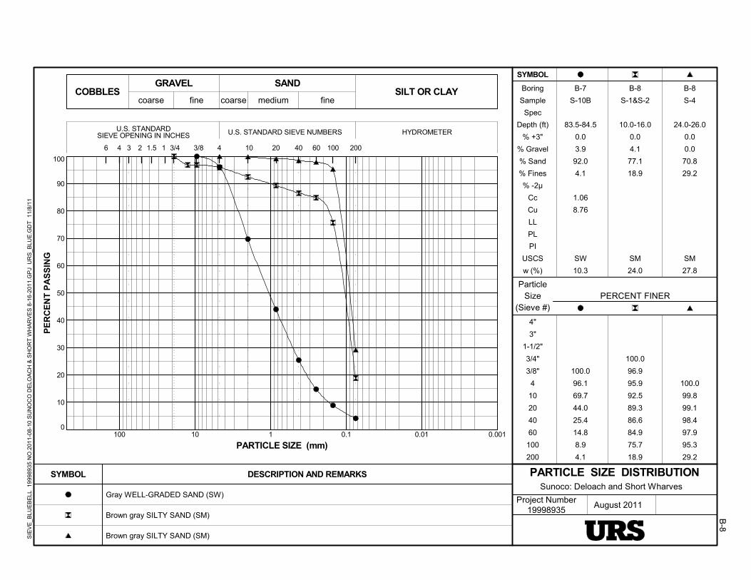
0
10
20
30
40
50
60
70
80
90
100
0.0010.010.1110100
4
4"
3"
1-1/2"
3/4"
3/8"
4
10
20
40
60
100
200
Project Number19998935
3
100.0
96.1
69.7
44.0
25.4
14.8
8.9
4.1
100.0
96.9
95.9
92.5
89.3
86.6
84.9
75.7
18.9
100.0
99.8
99.1
98.4
97.9
95.3
29.2
3/82
August 2011
10060
Sunoco: Deloach and Short Wharves
coarsecoarse fine medium fine
SIEVE OPENING IN INCHES U.S. STANDARD SIEVE NUMBERS HYDROMETER
SYMBOL
PE
RC
EN
T P
AS
SIN
G
PARTICLE SIZE (mm)
COBBLES
Gray WELL-GRADED SAND (SW)
Brown gray SILTY SAND (SM)
Brown gray SILTY SAND (SM)
Boring
Sample
Spec
Depth (ft)
% +3"
% Gravel
% Sand
% Fines
% -2µ
Cc
Cu
LL
PL
PI
USCS
w (%)
6 3/4
DESCRIPTION AND REMARKS
ParticleSize
(Sieve #)
1
PARTICLE SIZE DISTRIBUTION
SAND
1.5 4010 200
GRAVEL
4
SILT OR CLAY
20
SYMBOL
PERCENT FINER
U.S. STANDARD
B-8
B-7
S-10B
83.5-84.5
0.0
3.9
92.0
4.1
1.06
8.76
SW
10.3
B-8
S-1&S-2
10.0-16.0
0.0
4.1
77.1
18.9
SM
24.0
B-8
S-4
24.0-26.0
0.0
0.0
70.8
29.2
SM
27.8
SIE
VE
_BLU
EB
ELL
19
9989
35
NO
.201
1-0
8-10
SU
NO
CO
DE
LOA
CH
& S
HO
RT
WH
AR
VE
S 8
-16-
201
1.G
PJ
UR
S_B
LUE
.GD
T 1
1/8/
11

0
10
20
30
40
50
60
70
80
90
100
0.0010.010.1110100
4
4"
3"
1-1/2"
3/4"
3/8"
4
10
20
40
60
100
200
Project Number19998935
3
64.2
35.6
18.9
10.2
4.9
1.9
0.7
0.4
0.2
100.0
94.9
90.1
85.4
76.6
66.2
58.6
50.6
100.0
59.4
47.4
37.3
28.1
16.8
6.9
3.5
1.5
3/82
August 2011
10060
Sunoco: Deloach and Short Wharves
coarsecoarse fine medium fine
SIEVE OPENING IN INCHES U.S. STANDARD SIEVE NUMBERS HYDROMETER
SYMBOL
PE
RC
EN
T P
AS
SIN
G
PARTICLE SIZE (mm)
COBBLES
Gray WELL-GRADED GRAVEL with SAND (GW)
Brown SANDY SILT (ML)
Gray POORLY GRADED GRAVEL with SAND (GP)
Boring
Sample
Spec
Depth (ft)
% +3"
% Gravel
% Sand
% Fines
% -2µ
Cc
Cu
LL
PL
PI
USCS
w (%)
6 3/4
DESCRIPTION AND REMARKS
ParticleSize
(Sieve #)
1
PARTICLE SIZE DISTRIBUTION
SAND
1.5 4010 200
GRAVEL
4
SILT OR CLAY
20
SYMBOL
PERCENT FINER
U.S. STANDARD
B-9
B-8
S-8
39.0-41.0
0.0
81.1
18.7
0.2
1.67
9.06
GW
14.1
B-8
S-9
44.0-46.0
0.0
5.1
44.2
50.6
37
25
12
ML
32.7
B-8
S-12
59.0-61.0
0.0
52.6
45.9
1.5
0.36
32.98
GP
8.2
SIE
VE
_BLU
EB
ELL
19
9989
35
NO
.201
1-0
8-10
SU
NO
CO
DE
LOA
CH
& S
HO
RT
WH
AR
VE
S 8
-16-
201
1.G
PJ
UR
S_B
LUE
.GD
T 1
1/8/
11
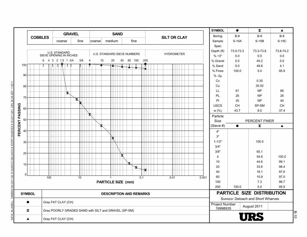
0
10
20
30
40
50
60
70
80
90
100
0.0010.010.1110100
4
4"
3"
1-1/2"
3/4"
3/8"
4
10
20
40
60
100
200
Project Number19998935
3
100.0
100.0
65.1
54.8
44.6
33.6
18.1
10.9
7.3
5.0
100.0
99.1
98.4
97.6
97.0
96.7
95.9
3/82
August 2011
10060
Sunoco: Deloach and Short Wharves
coarsecoarse fine medium fine
SIEVE OPENING IN INCHES U.S. STANDARD SIEVE NUMBERS HYDROMETER
SYMBOL
PE
RC
EN
T P
AS
SIN
G
PARTICLE SIZE (mm)
COBBLES
Gray FAT CLAY (CH)
Gray POORLY GRADED SAND with SILT and GRAVEL (SP-SM)
Gray FAT CLAY (CH)
Boring
Sample
Spec
Depth (ft)
% +3"
% Gravel
% Sand
% Fines
% -2µ
Cc
Cu
LL
PL
PI
USCS
w (%)
6 3/4
DESCRIPTION AND REMARKS
ParticleSize
(Sieve #)
1
PARTICLE SIZE DISTRIBUTION
SAND
1.5 4010 200
GRAVEL
4
SILT OR CLAY
20
SYMBOL
PERCENT FINER
U.S. STANDARD
B-10
B-8
S-15A
73.0-73.3
0.0
0.0
0.0
100.0
61
26
35
CH
43.7
B-8
S-15B
73.3-73.8
0.0
45.2
49.8
5.0
0.35
30.52
NP
NP
NP
SP-SM
8.5
B-8
S-15C
73.8-74.2
0.0
0.0
4.1
95.9
66
26
40
CH
37.4
SIE
VE
_BLU
EB
ELL
19
9989
35
NO
.201
1-0
8-10
SU
NO
CO
DE
LOA
CH
& S
HO
RT
WH
AR
VE
S 8
-16-
201
1.G
PJ
UR
S_B
LUE
.GD
T 1
1/8/
11

0
10
20
30
40
50
60
70
80
90
100
0.0010.010.1110100
4
4"
3"
1-1/2"
3/4"
3/8"
4
10
20
40
60
100
200
Project Number19998935
3
95.7
80.4
63.6
45.9
28.9
14.0
7.7
5.5
3.7
100.0
99.4
96.8
89.5
83.6
79.7
74.8
100.0
76.4
67.9
58.7
48.6
33.8
22.1
17.5
14.1
3/82
August 2011
10060
Sunoco: Deloach and Short Wharves
coarsecoarse fine medium fine
SIEVE OPENING IN INCHES U.S. STANDARD SIEVE NUMBERS HYDROMETER
SYMBOL
PE
RC
EN
T P
AS
SIN
G
PARTICLE SIZE (mm)
COBBLES
Gray POORLY GRADED SAND with GRAVEL (SP)
Brown gray LEAN CLAY with SAND (CL)
Brown SILTY SAND with GRAVEL (SM)
Boring
Sample
Spec
Depth (ft)
% +3"
% Gravel
% Sand
% Fines
% -2µ
Cc
Cu
LL
PL
PI
USCS
w (%)
6 3/4
DESCRIPTION AND REMARKS
ParticleSize
(Sieve #)
1
PARTICLE SIZE DISTRIBUTION
SAND
1.5 4010 200
GRAVEL
4
SILT OR CLAY
20
SYMBOL
PERCENT FINER
U.S. STANDARD
B-11
B-8
S-17A
83.0-85.0
0.0
36.4
59.9
3.7
0.67
13.14
SP
8.9
B-9
S-1
11-13
0.0
0.0
25.2
74.8
24
15
9
CL
24.3
B-9
S-2
17-19.5
0.0
32.1
53.9
14.1
SM
8.9
SIE
VE
_BLU
EB
ELL
19
9989
35
NO
.201
1-0
8-10
SU
NO
CO
DE
LOA
CH
& S
HO
RT
WH
AR
VE
S 8
-16-
201
1.G
PJ
UR
S_B
LUE
.GD
T 1
1/8/
11
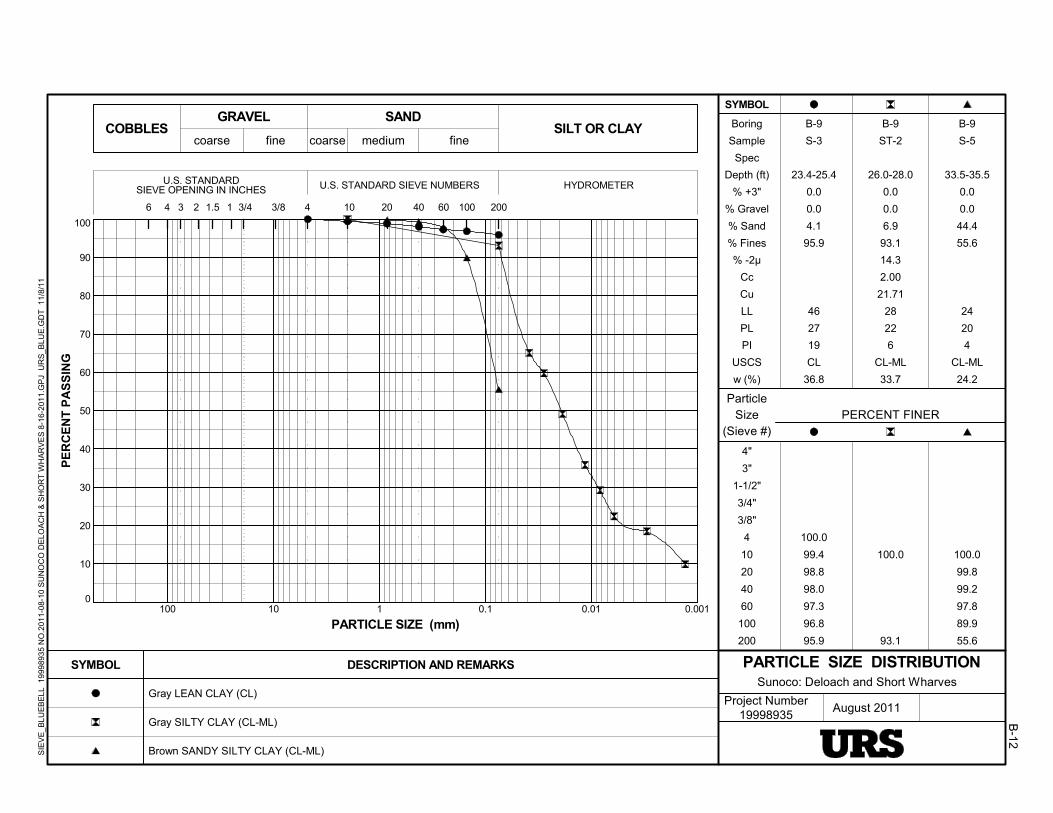
0
10
20
30
40
50
60
70
80
90
100
0.0010.010.1110100
4
4"
3"
1-1/2"
3/4"
3/8"
4
10
20
40
60
100
200
Project Number19998935
3
100.0
99.4
98.8
98.0
97.3
96.8
95.9
100.0
93.1
100.0
99.8
99.2
97.8
89.9
55.6
3/82
August 2011
10060
Sunoco: Deloach and Short Wharves
coarsecoarse fine medium fine
SIEVE OPENING IN INCHES U.S. STANDARD SIEVE NUMBERS HYDROMETER
SYMBOL
PE
RC
EN
T P
AS
SIN
G
PARTICLE SIZE (mm)
COBBLES
Gray LEAN CLAY (CL)
Gray SILTY CLAY (CL-ML)
Brown SANDY SILTY CLAY (CL-ML)
Boring
Sample
Spec
Depth (ft)
% +3"
% Gravel
% Sand
% Fines
% -2µ
Cc
Cu
LL
PL
PI
USCS
w (%)
6 3/4
DESCRIPTION AND REMARKS
ParticleSize
(Sieve #)
1
PARTICLE SIZE DISTRIBUTION
SAND
1.5 4010 200
GRAVEL
4
SILT OR CLAY
20
SYMBOL
PERCENT FINER
U.S. STANDARD
B-12
B-9
S-3
23.4-25.4
0.0
0.0
4.1
95.9
46
27
19
CL
36.8
B-9
ST-2
26.0-28.0
0.0
0.0
6.9
93.1
14.3
2.00
21.71
28
22
6
CL-ML
33.7
B-9
S-5
33.5-35.5
0.0
0.0
44.4
55.6
24
20
4
CL-ML
24.2
SIE
VE
_BLU
EB
ELL
19
9989
35
NO
.201
1-0
8-10
SU
NO
CO
DE
LOA
CH
& S
HO
RT
WH
AR
VE
S 8
-16-
201
1.G
PJ
UR
S_B
LUE
.GD
T 1
1/8/
11
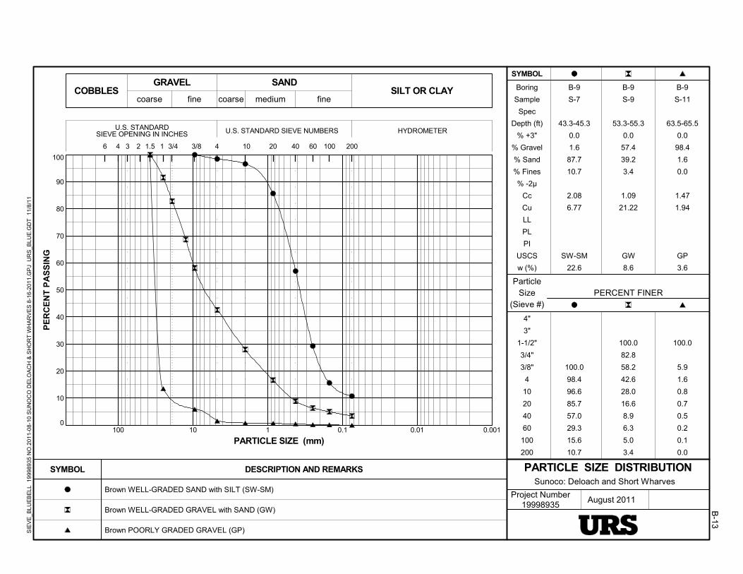
0
10
20
30
40
50
60
70
80
90
100
0.0010.010.1110100
4
4"
3"
1-1/2"
3/4"
3/8"
4
10
20
40
60
100
200
Project Number19998935
3
100.0
98.4
96.6
85.7
57.0
29.3
15.6
10.7
100.0
82.8
58.2
42.6
28.0
16.6
8.9
6.3
5.0
3.4
100.0
5.9
1.6
0.8
0.7
0.5
0.2
0.1
0.0
3/82
August 2011
10060
Sunoco: Deloach and Short Wharves
coarsecoarse fine medium fine
SIEVE OPENING IN INCHES U.S. STANDARD SIEVE NUMBERS HYDROMETER
SYMBOL
PE
RC
EN
T P
AS
SIN
G
PARTICLE SIZE (mm)
COBBLES
Brown WELL-GRADED SAND with SILT (SW-SM)
Brown WELL-GRADED GRAVEL with SAND (GW)
Brown POORLY GRADED GRAVEL (GP)
Boring
Sample
Spec
Depth (ft)
% +3"
% Gravel
% Sand
% Fines
% -2µ
Cc
Cu
LL
PL
PI
USCS
w (%)
6 3/4
DESCRIPTION AND REMARKS
ParticleSize
(Sieve #)
1
PARTICLE SIZE DISTRIBUTION
SAND
1.5 4010 200
GRAVEL
4
SILT OR CLAY
20
SYMBOL
PERCENT FINER
U.S. STANDARD
B-13
B-9
S-7
43.3-45.3
0.0
1.6
87.7
10.7
2.08
6.77
SW-SM
22.6
B-9
S-9
53.3-55.3
0.0
57.4
39.2
3.4
1.09
21.22
GW
8.6
B-9
S-11
63.5-65.5
0.0
98.4
1.6
0.0
1.47
1.94
GP
3.6
SIE
VE
_BLU
EB
ELL
19
9989
35
NO
.201
1-0
8-10
SU
NO
CO
DE
LOA
CH
& S
HO
RT
WH
AR
VE
S 8
-16-
201
1.G
PJ
UR
S_B
LUE
.GD
T 1
1/8/
11

0
10
20
30
40
50
60
70
80
90
100
0.0010.010.1110100
4
4"
3"
1-1/2"
3/4"
3/8"
4
10
20
40
60
100
200
Project Number19998935
3
100.0
100.0
58.9
48.7
40.5
32.6
22.5
12.3
9.5
6.6
66.6
44.4
37.1
28.5
22.1
14.3
8.7
6.5
4.3
3/82
August 2011
10060
Sunoco: Deloach and Short Wharves
coarsecoarse fine medium fine
SIEVE OPENING IN INCHES U.S. STANDARD SIEVE NUMBERS HYDROMETER
SYMBOL
PE
RC
EN
T P
AS
SIN
G
PARTICLE SIZE (mm)
COBBLES
Gray FAT CLAY (CH)
Gray POORLY GRADED GRAVEL with SILT and SAND (GP-GM)
Gray WELL-GRADED GRAVEL with SAND (GW)
Boring
Sample
Spec
Depth (ft)
% +3"
% Gravel
% Sand
% Fines
% -2µ
Cc
Cu
LL
PL
PI
USCS
w (%)
6 3/4
DESCRIPTION AND REMARKS
ParticleSize
(Sieve #)
1
PARTICLE SIZE DISTRIBUTION
SAND
1.5 4010 200
GRAVEL
4
SILT OR CLAY
20
SYMBOL
PERCENT FINER
U.S. STANDARD
B-14
B-9
S-12
68.5-70.5
0.0
0.0
0.0
100.0
56
20
36
CH
35.6
B-9
S-14
78.5-80.5
0.0
51.3
42.1
6.6
0.31
59.92
NP
NP
NP
GP-GM
9.1
B-9
S-16
89-91
0.0
62.9
32.8
4.3
1.16
58.65
GW
5.7
SIE
VE
_BLU
EB
ELL
19
9989
35
NO
.201
1-0
8-10
SU
NO
CO
DE
LOA
CH
& S
HO
RT
WH
AR
VE
S 8
-16-
201
1.G
PJ
UR
S_B
LUE
.GD
T 1
1/8/
11
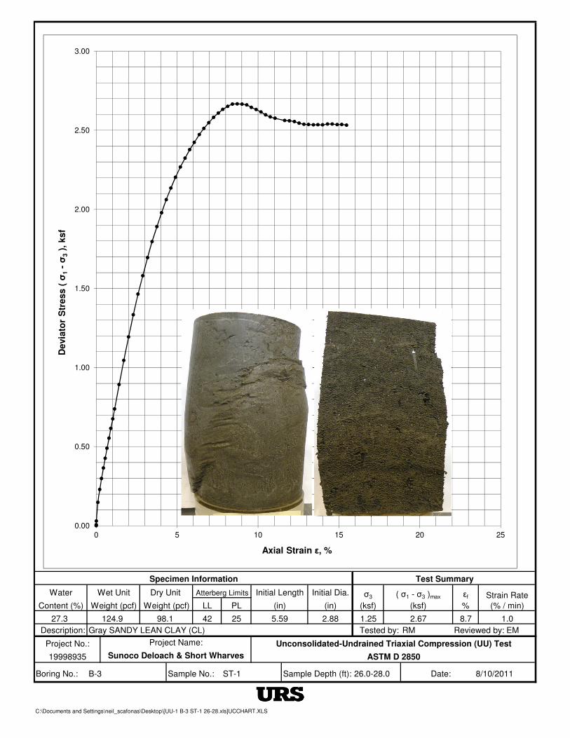
Water Initial Length Initial Dia.
Content (%) Weight (pcf) Weight (pcf) LL PL (in) (in)
27.3 124.9 98.1 42 25 5.59 2.88
Description: Tested by: RM EM
Project No.:
19998935
Boring No.: Sample No.: 26.0-28.0 Date:
C:\Documents and Settings\neil_scafonas\Desktop\[UU-1 B-3 ST-1 26-28.xls]UCCHART.XLS
Reviewed by:
Strain Rate
(% / min)
σ3
(ksf)
8/10/2011
εf
%
1.25 2.67
Gray SANDY LEAN CLAY (CL)
8.7 1.0
Specimen Information Test Summary
Wet Unit Dry Unit Atterberg Limits ( σ1 - σ3 )max
(ksf)
ST-1
Project Name:
Sunoco Deloach & Short Wharves
B-3
Unconsolidated-Undrained Triaxial Compression (UU) Test
ASTM D 2850
Sample Depth (ft):
0.00
0.50
1.00
1.50
2.00
2.50
3.00
0 5 10 15 20 25
Devia
tor
Str
ess (
σ1
-σ
3),
ksf
Axial Strain ε, %
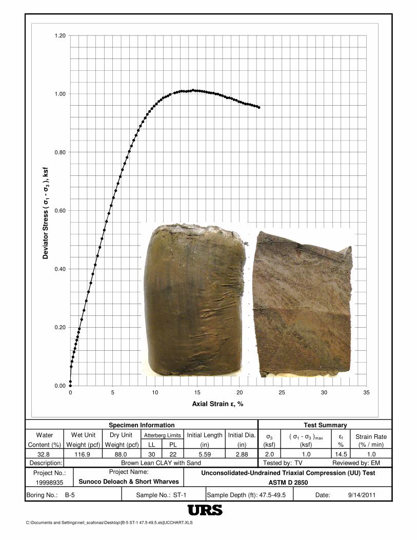
Water Initial Length Initial Dia.
Content (%) Weight (pcf) Weight (pcf) LL PL (in) (in)
32.8 116.9 88.0 30 22 5.59 2.88
Description: Tested by: TV EM
Project No.:
19998935
Boring No.: 47.5-49.5 Date:
C:\Documents and Settings\neil_scafonas\Desktop\[B-5 ST-1 47.5-49.5.xls]UCCHART.XLS
Reviewed by:
Strain Rate
(% / min)
σ3
(ksf)
9/14/2011
εf
%
2.0 1.0
Brown Lean CLAY with Sand
14.5 1.0
Specimen Information Test Summary
Wet Unit Dry Unit Atterberg Limits ( σ1 - σ3 )max
(ksf)
Project Name:
Sunoco Deloach & Short Wharves
ST-1Sample No.:B-5
Unconsolidated-Undrained Triaxial Compression (UU) Test
ASTM D 2850
Sample Depth (ft):
0.00
0.20
0.40
0.60
0.80
1.00
1.20
0 5 10 15 20 25 30 35
De
via
tor
Str
es
s (
σ1
-σ
3),
ks
f
Axial Strain ε, %
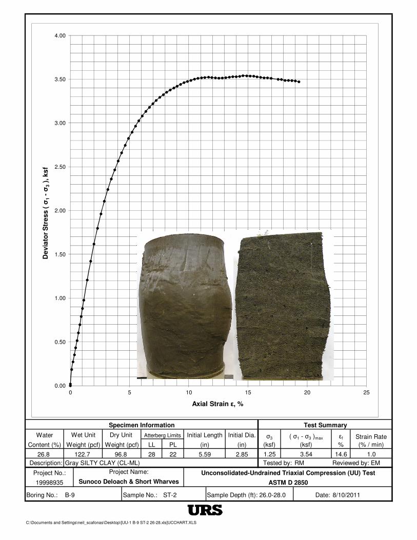
Water Initial Length Initial Dia.
Content (%) Weight (pcf) Weight (pcf) LL PL (in) (in)
26.8 122.7 96.8 28 22 5.59 2.85
Description: Tested by: RM EM
Project No.:
19998935
Boring No.: Sample No.: 26.0-28.0 Date:
C:\Documents and Settings\neil_scafonas\Desktop\[UU-1 B-9 ST-2 26-28.xls]UCCHART.XLS
ST-2
Project Name:
Sunoco Deloach & Short Wharves
B-9
Unconsolidated-Undrained Triaxial Compression (UU) Test
ASTM D 2850
Sample Depth (ft):
Gray SILTY CLAY (CL-ML)
14.6 1.0
Specimen Information Test Summary
Wet Unit Dry Unit Atterberg Limits ( σ1 - σ3 )max
(ksf)
Reviewed by:
Strain Rate
(% / min)
σ3
(ksf)
8/10/2011
εf
%
1.25 3.54
0.00
0.50
1.00
1.50
2.00
2.50
3.00
3.50
4.00
0 5 10 15 20 25
De
via
tor
Str
es
s (
σ1
-σ
3),
ks
f
Axial Strain ε, %