Embed Size (px)
Citation preview
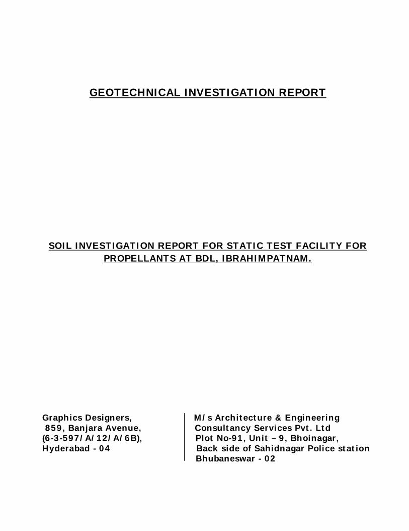
GEOTECHNICAL INVESTIGATION REPORT
SOIL INVESTIGATION REPORT FOR STATIC TEST FACILITY FOR PROPELLANTS AT BDL, IBRAHIMPATNAM.
Graphics Designers, M/s Architecture & Engineering 859, Banjara Avenue, Consultancy Services Pvt. Ltd (6-3-597/A/12/A/6B), Plot No-91, Unit – 9, Bhoinagar, Hyderabad - 04 Back side of Sahidnagar Police station Bhubaneswar - 02

GEOTECHNICAL INVESTIGATION REPORT: ARCHITECTURE & ENGINEERING CONSULTANCY SERVICES PVT. LTD.
CONTENTS
Chapter No. Particulars Page No
One Introduction
01
Two
Field Operations 02 - 03
Three Information about Laboratory Tests 04 - 05
Four Bore Logs 06 - 10
Five Laboratory Test Results 11 - 15
Six Calculation of Safe Bearing Capacity and settlement
16 - 65
Seven Calculation of Safe Bearing Capacity of Rock 66
Eight Analysis of the Sub Surface Investigation 67 - 68
Nine Abstract of Safe Bearing Capacity (SBC) 69 - 70
Ten Conclusion and Recommendations.
71
Eleven Location Map 72
GEOTECHNICAL INVESTIGATION REPORT: ARCHITECTURE & ENGINEERING CONSULTANCY SERVICES PVT. LTD.
Chapter One: Introduction
Sub-surface exploration plays an important role in the design for the
construction of buildings and bridges. Before design, it is essential to study the
behavior as well as the engineering properties of the sub-surface strata, which
promotes the design more economic and perfect. It also enables to take precaution
in the design for the structural safety. “Soil Investigation for Static facility for Propellants at BDL, Ibrahimpatnam” was decided to be designed on the basis of
the sub-surface investigation test results. As such, the Graphics Designers,
Hyderabd entrusted the sub-surface investigation work to M/s Architecture &
Engineering Consultancy Services Pvt. Ltd vide work order No. –GD/AECS/2014-
272 and Date:-13/05/2014. The scope of work comprised of boring five boreholes at
site. The fieldwork included making of boreholes by Wash/Rotary Boring method.
The scope also included conducting Standard Penetration Tests at regular intervals
and collecting soil/rock samples for identification and logging purposes, and the
collected soil and rock samples were tested in the Base Laboratory and the data
were analyzed.
Based on the above, this report presents the Bore Logs, Laboratory & Field
Test results. On the basis of field & laboratory test results and their analysis,
suitable foundations have been suggested.
GEOTECHNICAL INVESTIGATION REPORT: ARCHITECTURE & ENGINEERING CONSULTANCY SERVICES PVT. LTD.
Chapter Two: Field Operations 2.1 General: In an attempt for optimization in the design of foundation for the proposed structure to be constructed at this site, Geo-technical Investigation was done. The entire investigation work had been divided mainly into two parts. (i) Field works & (ii) Laboratory tests. Field works determine the types of sub-soil deposit and their characteristics. Laboratory tests help in determining the relevant geo-technical properties of the sub-surface deposits leading to finalization of foundation depth of the structure basing on Bearing Capacities of the foundation strata as well as the influence zone. Final depths of boring and observation of water table for each borehole are given below. 2.2 Boring & In-Situ Tests:
Wash/Rotary boring method was adopted to bore holes to the required depth. UDS & SPT were conducted at regular intervals and the soil samples were brought to the laboratory with proper identification and labeling. Standard split spoon sampler was used for conducting Standard Penetration Test. The number of blows required to drive the sampler for the 1st, 2nd & 3rd 15cm depths were recorded. The total number of blows required to drive the split spoon sampler due to the free fall of a 63.5kg hammer through a distance of 75 cm for the 2nd and 3rd 15cm penetration were taken together as the field ‘N’ value or the standard penetration test (resistance) of the soil.
After the penetration to full depth, the sampler was carefully pulled out. The cutting shoe and the head were removed. The soil samples were then sealed in polythene bags and labeled properly by indicating the depth of bore hole mark, reference no. etc for visual inspection and identification of soil samples for logging of the bore holes.
The field ‘N’ values recorded at various depths have been reported in the summarized data sheet. Test results of soil samples & their bore logs were presented separately in the sub-soil report. Based on the above, this report presents the Bore Logs, Laboratory & Field Test results.

GEOTECHNICAL INVESTIGATION REPORT: ARCHITECTURE & ENGINEERING CONSULTANCY SERVICES PVT. LTD.
Undisturbed soil samples were carefully extracted in such a manner that the moisture content and structure of soil did not get altered. Standard open tube sampler was used for the collection of undisturbed soil samples. Each end of the sampling tube was carefully sealed with wax, the bore hole number and depth were indicated on the tube for proper identification. 2.3 Sampling: Representative soil samples were collected from the borehole confirming to IS: 1892-1979. Collected samples were properly sealed in polythene bags and labeled for proper identification during testing. The disturbed samples were used for classification of soils as per IS: 1498-1970. 2.4 Ground Water Table: Observation of ground water table is important since it influences the bearing capacity of soil in different seasons. When the foundation remains submerged under water the bearing capacity is to be calculated considering the water table correction factor. Therefore while conducting tests during dry season, it is always necessary to enquire about the ground water table level.
Bore Hole No. Termination Depth in m.
Water Table from the G.L. in m.
BH – 1 10.0 m. Not encountered within the drilling depth
BH – 2 6.0 m. - do - BH – 3 6.0 m. - do - BH – 4 6.0 m. - do - BH – 5 6.0 m. - do -
GEOTECHNICAL INVESTIGATION REPORT: ARCHITECTURE & ENGINEERING CONSULTANCY SERVICES PVT. LTD.
Chapter Three: Information about Laboratory Tests
Laboratory test conforming to relevant Indian Standard specifications were conducted on the soil samples collected from both the boreholes as detailed below. All laboratory tests were conducted as per SP: 36 Part-1 1987 of BIS. 3.1 Grain Size Analysis: To obtain information concerning the type of soil met at various depths and to classify each soil strata, grain size analysis were carried out as per IS: 2720 (Part-IV). The results have been presented in the summarized data sheet. 3.2 Index Properties: Soil consistency refers to the resistance of the soil offered against forces that tend to deform or rupture the soil aggregate. Consistency limits indicate the soil moisture content limits for various states of consistency. The consistency limits include Liquid Limit (L.L), Plastic Limit (P.L), and Shrinkage Limit (S.L). The difference between the numerical values of liquid limit and plastic limit of the soil is called the Plasticity Index (P.I). It indicates the range of moisture content over which the soil exhibits plasticity. It is determined as per the procedure laid down in IS: 2720 (Part-IV). Plasticity index was computed. Results of liquid limit and plasticity index have been reported in the summarized data sheets. 3.3 Specific Gravity:
The specific gravity of the soil sample is the ratio of the mass of a given volume of soil sample in air to the mass of an equal volume of water at 270C. Specific gravity of soil sample was determined as per the provisions of IS: 2720 (Part –III). Specific gravity of soil sample obtained during the test has been reported in the summarized data sheet.
3.4 Void Ratio:
Void ratio of different soil samples were determined in through appropriate formula.

GEOTECHNICAL INVESTIGATION REPORT: ARCHITECTURE & ENGINEERING CONSULTANCY SERVICES PVT. LTD.
3.5 DFS:
Differential free swell index of different soil samples were determined in the laboratory and are mentioned in the laboratory test result sheet. 3.6 Final Logging: The logging of the boreholes as obtained during field work were checked with the disturbed and undisturbed soil samples and scrutinized with the findings of laboratory tests to avoid discrepancies, if any. The bore logs have been reported in the summarized data sheets. 3.7 Results of Test: The findings of various in-situ and laboratory tests conducted on disturbed /SPT samples have been reported in the summarized data sheet. The soil has been classified into different categories base on their Engineering properties. A careful study of the sub soil strata was made in accordance with the provisions of IS: 1498-1970 to find out their suitability as foundation materials.

S.P
.T.
valu
e =
2+
3 =
N
No.
of
blo
ws
for
2nd
15 c
m p
enetr
ation
(2)
No.
of
blo
ws
for
3rd
15 c
m p
enetr
ation
(3)
Rem
arks
No.
of
blo
ws
for
1st
15 c
m p
enetr
ation
(1)
Typ
e of
sam
ple
colle
cted
Typ
e of
soi
l st
rata
0.0
Sl. N
o
Pen
etra
tion
of
soil
stra
ta in m
.
Thic
kness
of
soil
stra
ta in m
.
Dep
th f
rom
gro
und lev
el in m
.
Gra
phic
al re
pre
senta
tion
of so
il st
rata
R.L
. in
mt.
01 02 03 04 05 06 07 08 09 10 11 12 13
3.0
CHAPTER FOUR - RECORD OF BORING
Name of Consultants: Architecture & Engineering Consultancy Services Pvt. Ltd.Name of the client: Graphics Designers, Secunderabad.Name of Work :Soil Investigation for Static test facility for Propellants at BDL, Ibrahimpatnam.Ground surface level: Boring No:01Type of boring: Rotary DrilingDiameter of boring: 100mm Date of boring started: 28/05/2014Inclination: Vertical Date of boring completed:02/06/2014Ground water table:Not found
01
----03
----
----02
S.P.T.1.0
2.0 S.P.T.
Rock
3.0
S.P.T. >50 0.09--- --- >50
>50 0.00--- --- >50
>50 0.00--- --- >50
SPT Rebounded, brokenrock pieces collected
4.504
6.005
7.506
9.007
10.008
6.0
----
----
----
----
----
Poorly gradedsand
1.0ROCK
Rock
--- ---Core recovery-33.0%RQD - Nil--- --- ---
SPT Rebounded,DS Collected.
S.P.T. >50 0.05--- --- >50SPT ReboundedDS Collected.
S.P.T. >50 0.04--- --- >50SPT ReboundedDS Collected.
S.P.T. >50 0.06--- --- >50SPT ReboundedDS Collected.
S.P.T. >50 0.00--- --- >50SPT Rebounded,
sample not recovered.
SPT Rebounded, brokenrock pieces collected

S.P
.T.
valu
e =
2+
3 =
N
No.
of
blo
ws
for
2nd
15 c
m p
enet
ration (
2)
No.
of
blo
ws
for
3rd
15 c
m p
enet
ration (
3)
Rem
ark
s
No.
of
blo
ws
for
1st
15 c
m p
enet
ration (
1)
Type o
f sa
mple
colle
cted
Typ
e of
soil
stra
ta
0.0
Sl. N
o
Penetr
ation o
f so
il st
rata
in m
.
Thic
kness
of
soil
stra
ta in m
.
Dep
th f
rom
gro
und lev
el in m
.
Gra
phic
al re
pre
senta
tion o
f so
il st
rata
R.L
. in
mt.
01 02 03 04 05 06 07 08 09 10 11 12 13
3.0
01
----03
----
----02
S.P.T.1.0
2.0
6.0---- S.P.T. >50 0.00--- --- >5006
S.P.T.
Poorly gradedsand
3.05
S.P.T. >50 0.05--- --- >50SPT ReboundedDS Collected.
10 0.4512 15 27SPT conductedDS Collected.
Name of Consultants: Architecture & Engineering Consultancy Services Pvt. Ltd.Name of the client: Graphics Designers, Secunderabad.Name of Work :Soil Investigation for Static test facility for Propellants at BDL, Ibrahimpatnam.Ground surface level: Boring No:02Type of boring: Rotary DrilingDiameter of boring: 100mm Date of boring started: 08/06/2014Inclination: Vertical Date of boring completed:09/06/2014Ground water table:Not found
4.5052.95
----
Rock
S.P.T. >50 0.00--- --- >50
04 3.05 --- ------ --- --- ---
SPT Rebounded, brokenrock pieces collected
SPT Rebounded, brokenrock pieces collected
14 0.4520 20 40SPT conductedDS Collected.

S.P
.T.
valu
e =
2+
3 =
N
No.
of
blo
ws
for
2nd
15 c
m p
enet
ration
(2)
No.
of
blo
ws
for
3rd
15 c
m p
enet
ration
(3)
Rem
arks
No.
of
blo
ws
for
1st
15 c
m p
enet
ration
(1)
Typ
e of
sam
ple
colle
cted
Typ
e of
soi
l st
rata
0.0
Sl. N
o
Penetr
ati
on o
f so
il st
rata
in m
.
Thic
kness
of
soil
stra
ta in m
.
Depth
fro
m g
round lev
el in m
.
Gra
phic
al r
epre
senta
tion
of
soil
stra
ta
R.L
. in
mt.
01 02 03 04 05 06 07 08 09 10 11 12 13
3.0
01
----04
----
----03
1.0
2.0
4.95
Name of Consultants: Architecture & Engineering Consultancy Services Pvt. Ltd.Name of the client: Graphics Designers, Secunderabad.Name of Work :Soil Investigation for Static test facility for Propellants at BDL, Ibrahimpatnam.Ground surface level: Boring No:03Type of boring: Rotary DrilingDiameter of boring: 100mm Date of boring started: 02/06/2014Inclination: Vertical Date of boring completed:03/06/2014Ground water table:Not found
1.05S.P.T.
Poorly gradedsand mixed
with silt >50 0.05--- --- >50SPT ReboundedDS Collected.
02 1.05 --- ------ --- --- ---
4.505
6.006
S.P.T.
S.P.T. >50 0.00--- --- >50
>50 0.00--- --- >50
S.P.T. >50 0.00--- --- >50
S.P.T. >50 0.00--- --- >50
Rock
----
----
SPT Rebounded, brokenrock pieces collected
SPT Rebounded, brokenrock pieces collected
SPT Rebounded, brokenrock pieces collected
SPT Rebounded, brokenrock pieces collected

S.P
.T.
valu
e =
2+
3 =
N
No.
of
blo
ws
for
2nd
15 c
m p
enet
ration
(2)
No.
of
blo
ws
for
3rd
15 c
m p
enet
ration
(3)
Rem
arks
No.
of
blo
ws
for
1st
15 c
m p
enet
ration
(1)
Typ
e o
f sa
mple
col
lect
ed
Typ
e o
f so
il st
rata
0.0
Sl. N
o
Penetr
ation o
f so
il st
rata
in m
.
Thic
kness
of
soil
stra
ta in
m.
Depth
fro
m g
round le
vel i
n m
.
Gra
phic
al re
pre
senta
tion o
f so
il st
rata
R.L
. in
mt.
01 02 03 04 05 06 07 08 09 10 11 12 13
3.0
01
----03
----
----02
1.0
2.0
6.0
Name of Consultants: Architecture & Engineering Consultancy Services Pvt. Ltd.Name of the client: Graphics Designers, Secunderabad.Name of Work :Soil Investigation for Static test facility for Propellants at BDL, Ibrahimpatnam.Ground surface level: Boring No:04Type of boring: Rotary DrilingDiameter of boring: 100mm Date of boring started: 04/06/2014Inclination: Vertical Date of boring completed:05/06/2014Ground water table:Not found
4.504
6.005
S.P.T.
S.P.T. >50 0.00--- --- >50
>50 0.00--- --- >50
S.P.T. >50 0.00--- --- >50
S.P.T. >50 0.00--- --- >50
Rock
----
----
S.P.T. >50 0.00--- --- >50
SPT Rebounded, brokenrock pieces collected
SPT Rebounded, brokenrock pieces collected
SPT Rebounded, brokenrock pieces collected
SPT Rebounded, brokenrock pieces collected
SPT Rebounded, brokenrock pieces collected

S.P
.T.
valu
e =
2+
3 =
N
No.
of
blo
ws
for
2nd
15 c
m p
enet
ration (
2)
No.
of
blo
ws
for
3rd
15 c
m p
enet
ration (
3)
Rem
ark
s
No.
of
blo
ws
for
1st
15 c
m p
enet
ration (
1)
Type o
f sa
mple
colle
cted
Typ
e of
soil
stra
ta
0.0
Sl. N
o
Penetr
ation o
f so
il st
rata
in m
.
Thic
kness
of
soil
stra
ta in m
.
Dep
th f
rom
gro
und lev
el in m
.
Gra
phic
al re
pre
senta
tion
of so
il st
rata
R.L
. in
mt.
01 02 03 04 05 06 07 08 09 10 11 12 13
3.0
01
----04
----
----02
S.P.T.1.0
2.0
6.0----07
S.P.T.
Silty sandmixed with
gravel
2.4
S.P.T. >50 0.04--- --- >50SPT ReboundedDS Collected.
15 0.4520 21 41SPT conductedDS Collected.
Name of Consultants: Architecture & Engineering Consultancy Services Pvt. Ltd.Name of the client: Graphics Designers, Secunderabad.Name of Work :Soil Investigation for Static test facility for Propellants at BDL, Ibrahimpatnam.Ground surface level: Boring No:05Type of boring: Rotary DrilingDiameter of boring: 100mm Date of boring started: 04/06/2014Inclination: Vertical Date of boring completed:05/06/2014Ground water table:Not found
4.5062.96
----
05 3.04 --- ------ --- --- ---
2.403 --- ------ --- --- ---Poorly gradedsand mixed
with silt
18 0.4023 >50 >50SPT reboundedDS Collected.
0.64
----
ROCK
Rock
--- ---Core recovery-85.0%RQD - 30.0%--- --- ---
ROCK --- ---Core recovery-90.0%RQD - 53.0%--- --- ---

CHAPTER FIVE - LABORATORY TEST RESULTS SUB SOIL INVESTIGATION TEST RESULT OF THE SOIL SAMPLES COLLECTED DURING BORING OF B.H. No. 01
TEST CONDUCTED AS PER IS: 2720 (Pt. I, Pt. II, Pt. III , Pt. IV , Pt. V, Pt. XI / Pt. XIII , Pt. XXXX ) AND IS: 1498 – 1970
Sl. N
o
Soil
sam
ple
colle
cted
Type
of c
olle
ctio
n
Grain size analysis Atterberg’s Limits
Fiel
d M
oist
ure
Con
tent
in
%
Bul
k de
nsity
in g
m/c
c.
Spec
ific
grav
ity
D.F
.S.
In %
Fiel
d S.
P.T.
Val
ue
Gro
up o
f soi
l.
Fine
Gra
vel I
n %
(2
0mm
to 4
.75m
m)
Coa
rse
Sand
In %
(4
.75m
m to
2.0
mm
)
Med
ium
San
d In
%
(2.0
mm
to 0
.425
mm
)
Fine
San
d in
%
(0.4
25m
m to
0.0
75m
m)
Silt
(S)&
Cla
y (C
) in
%
(0.0
75m
m to
0.0
01m
m)
Liqu
id L
imit
In %
Plas
tic L
imit
In %
Plas
ticity
Inde
x in
%
1 From 0.0m to 1.0m depth Rock Rock strata, broken rock pieces collected ----- ----
2 At 1.0m depth SPT STP Rebounded, sample not recovered N>50 ----
3 From 1.0m to 2.0m depth Rock Rock strata, broken rock pieces collected ----- ----
4 At 2.0m depth SPT STP Rebounded, sample not recovered N>50 ----
5 From 2.0m to 3.0m depth Rock Rock strata, broken rock pieces collected ----- ----
6 At 3.0m depth SPT 10.32 6.03 35.68 45.06 2.91 16.0 Np ---- 7.22 1.825 2.65 0.0 N > 50 SP
7 At 4.5m depth SPT 8.63 12.22 44.52 33.55 1.08 16.0 Np ---- 7.30 1.879 2.65 0.0 N > 50 SP
8 At 6.0m depth SPT 0.32 0.40 64.42 32.16 2.70 18.0 Np ---- 7.54 1.856 2.65 0.0 N > 50 SP
9 At 7.5m depth SPT 0.00 0.26 13.18 71.18 15.38 20.0 Np ---- 8.76 1.848 2.65 0.0 N > 50 SP
10 At 9.0m depth SPT STP Rebounded, sample not recovered N > 50 ----
11 From 9.0m to 10.0m depth Rock Rock strata, core recovery = 33.0% and RQD = Nil

SUB SOIL INVESTIGATION TEST RESULT OF THE SOIL SAMPLES COLLECTED DURING BORING OF B.H. No. 02
TEST CONDUCTED AS PER IS: 2720 (Pt. I, Pt. II, Pt. III , Pt. IV , Pt. V, Pt. XI / Pt. XIII , Pt. XXXX ) AND IS: 1498 – 1970
Sl. N
o
Soil
sam
ple
colle
cted
Type
of c
olle
ctio
n Grain size analysis Atterberg’s Limits
Fiel
d M
oist
ure
Con
tent
in
%
Bul
k de
nsity
in g
m/c
c.
Spec
ific
grav
ity
D.F
.S.
In %
Fiel
d S.
P.T.
Val
ue
Gro
up o
f soi
l.
Fine
Gra
vel I
n %
(2
0mm
to 4
.75m
m)
Coa
rse
Sand
In %
(4
.75m
m to
2.0
mm
)
Med
ium
San
d In
%
(2.0
mm
to 0
.425
mm
)
Fine
San
d in
%
(0.4
25m
m to
0.0
75m
m)
Silt
(S)&
Cla
y (C
) in
%
(0.0
75m
m to
0.0
01m
m)
Liqu
id L
imit
In %
Plas
tic L
imit
In %
Plas
ticity
Inde
x in
%
1 At 1.0m depth SPT 3.72 2.33 79.33 14.44 0.18 16.0 Np ---- 6.04 1.828 2.65 0.0 N =27 SP
2 At 2.0m depth SPT 0.19 1.24 68.57 26.73 3.27 17.0 Np ---- 6.87 1.820 2.65 0.0 N = 40 SP
3 At 3.0m depth SPT 0.23 0.42 72.18 25.16 2.01 16.0 Np ---- 6.56 1.885 2.65 0.0 N > 50 SP
4 From 3.05m to 4.5m depth Rock Rock strata, broken rock pieces collected ----- ----
5 At 4.5m depth SPT STP Rebounded, sample not recovered N>50 ----
6 From4.5m to 6.0m depth
Soft Rock Rock strata, broken rock pieces collected ----- ----
7 At 6.0m depth SPT STP Rebounded, sample not recovered N>50 ----
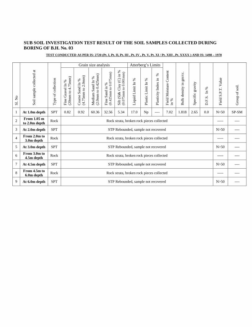
SUB SOIL INVESTIGATION TEST RESULT OF THE SOIL SAMPLES COLLECTED DURING BORING OF B.H. No. 03
TEST CONDUCTED AS PER IS: 2720 (Pt. I, Pt. II, Pt. III , Pt. IV , Pt. V, Pt. XI / Pt. XIII , Pt. XXXX ) AND IS: 1498 – 1970
Sl. N
o
Soil
sam
ple
colle
cted
at
Type
of c
olle
ctio
n
Grain size analysis Atterberg’s Limits
Fiel
d M
oist
ure
Con
tent
in
%
Bul
k de
nsity
in g
m/c
c.
Spec
ific
grav
ity
D.F
.S.
In %
Fiel
d S.
P.T.
Val
ue
Gro
up o
f soi
l.
Fine
Gra
vel I
n %
(2
0mm
to 4
.75m
m)
Coa
rse
Sand
In %
(4
.75m
m to
2.0
mm
)
Med
ium
San
d In
%
(2.0
mm
to 0
.425
mm
)
Fine
San
d in
%
(0.4
25m
m to
0.0
75m
m)
Silt
(S)&
Cla
y (C
) in
%
(0.0
75m
m to
0.0
01m
m)
Liqu
id L
imit
In %
Plas
tic L
imit
In %
Plas
ticity
Inde
x in
%
1 At 1.0m depth SPT 0.82 0.92 60.36 32.56 5.34 17.0 Np ---- 7.02 1.818 2.65 0.0 N>50 SP-SM
2 From 1.05 m to 2.0m depth Rock Rock strata, broken rock pieces collected ----- ----
3 At 2.0m depth SPT STP Rebounded, sample not recovered N>50 ----
4 From 2.0m to 3.0m depth Rock Rock strata, broken rock pieces collected ----- ----
5 At 3.0m depth SPT STP Rebounded, sample not recovered N>50 ----
6 From 3.0m to 4.5m depth Rock Rock strata, broken rock pieces collected ----- ----
7 At 4.5m depth SPT STP Rebounded, sample not recovered N>50 ----
8 From 4.5m to 6.0m depth Rock Rock strata, broken rock pieces collected ----- ----
9 At 6.0m depth SPT STP Rebounded, sample not recovered N>50 ----

SUB SOIL INVESTIGATION TEST RESULT OF THE SOIL SAMPLES COLLECTED DURING BORING OF B.H. No. 04
TEST CONDUCTED AS PER IS: 2720 (Pt. I, Pt. II, Pt. III , Pt. IV , Pt. V, Pt. XI / Pt. XIII , Pt. XXXX ) AND IS: 1498 – 1970
Sl. N
o
Soil
sam
ple
colle
cted
at
Type
of c
olle
ctio
n
Grain size analysis Atterberg’s Limits
Fiel
d M
oist
ure
Con
tent
in
%
Bul
k de
nsity
in g
m/c
c.
Spec
ific
grav
ity
D.F
.S.
In %
Fiel
d S.
P.T.
Val
ue
Gro
up o
f soi
l.
Fine
Gra
vel I
n %
(2
0mm
to 4
.75m
m)
Coa
rse
Sand
In %
(4
.75m
m to
2.0
mm
)
Med
ium
San
d In
%
(2.0
mm
to 0
.425
mm
)
Fine
San
d in
%
(0.4
25m
m to
0.0
75m
m)
Silt
(S)&
Cla
y (C
) in
%
(0.0
75m
m to
0.0
01m
m)
Liqu
id L
imit
In %
Plas
tic L
imit
In %
Plas
ticity
Inde
x in
%
1 From 0.0 m to 1.0m depth Rock Rock strata, broken rock pieces collected ----- ----
2 At 1.0m depth SPT STP Rebounded, sample not recovered N>50 ----
3 From 1.0 m to 2.0m depth Rock Rock strata, broken rock pieces collected ----- ----
4 At 2.0m depth SPT STP Rebounded, sample not recovered N>50 ----
5 From 2.0m to 3.0m depth Rock Rock strata, broken rock pieces collected ----- ----
6 At 3.0m depth SPT STP Rebounded, sample not recovered N>50 ----
7 From 3.0m to 4.5m depth Rock Rock strata, broken rock pieces collected ----- ----
8 At 4.5m depth SPT STP Rebounded, sample not recovered N>50 ----
9 From 4.5m to 6.0m depth Rock Rock strata, broken rock pieces collected ----- ----
10 At 6.0m depth SPT STP Rebounded, sample not recovered N>50 ----

SUB SOIL INVESTIGATION TEST RESULT OF THE SOIL SAMPLES COLLECTED DURING BORING OF B.H. No. 05
TEST CONDUCTED AS PER IS: 2720 (Pt. I, Pt. II, Pt. III , Pt. IV , Pt. V, Pt. XI / Pt. XIII , Pt. XXXX ) AND IS: 1498 – 1970
Sl. N
o
Soil
sam
ple
colle
cted
at
Type
of c
olle
ctio
n
Grain size analysis Atterberg’s Limits
Fiel
d M
oist
ure
Con
tent
in
%
Bul
k de
nsity
in g
m/c
c.
Spec
ific
grav
ity
D.F
.S.
In %
Fiel
d S.
P.T.
Val
ue
Gro
up o
f soi
l.
Fine
Gra
vel I
n %
(2
0mm
to 4
.75m
m)
Coa
rse
Sand
In %
(4
.75m
m to
2.0
mm
)
Med
ium
San
d In
%
(2.0
mm
to 0
.425
mm
)
Fine
San
d in
%
(0.4
25m
m to
0.0
75m
m)
Silt
(S)&
Cla
y (C
) in
%
(0.0
75m
m to
0.0
01m
m)
Liqu
id L
imit
In %
Pla
stic
Lim
it In
%
Plas
ticity
Inde
x in
%
1 1.0m depth SPT 15.95 15.00 41.5 13.15 14.40 20.0 Np ---- 7.23 1.802 2.65 0.0 N = 41 SM
2 2.0m depth SPT 5.00 10.06 33.94 27.10 23.90 24.0 Np ---- 7.12 1.810 2.65 0.0 N >50 SM
3 3.0m depth SPT 0.00 0.00 64.46 30.10 5.44 17.0 Np ---- 7.06 1.874 2.65 0.0 N > 50 SP-SM
4 From 3.04m to 4.5m depth Rock Rock strata, core recovery = 85.0% and RQD = 30.0%
5 From4.5m to 6.0m depth Rock Rock strata, core recovery = 92.0% and RQD = 53.0%
Soil Investigation Data
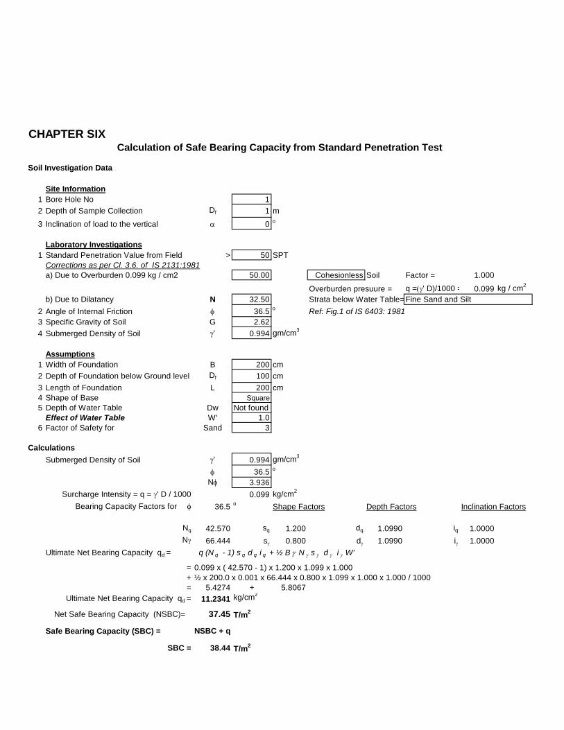
Site Information1 Bore Hole No 12 Depth of Sample Collection Df 1 m
3 Inclination of load to the vertical a 0 o
Laboratory Investigations1 Standard Penetration Value from Field > 50 SPT
Corrections as per Cl. 3.6. of IS 2131:1981a) Due to Overburden 0.099 kg / cm2 50.00 Cohesionless Soil Factor = 1.000
Overburden presuure = q =(g' D)/1000 = 0.099 kg / cm2
b) Due to Dilatancy N 32.502 Angle of Internal Friction f 36.5 o Ref: Fig.1 of IS 6403: 19813 Specific Gravity of Soil G 2.624 Submerged Density of Soil g' 0.994 gm/cm3
Assumptions1 Width of Foundation B 200 cm2 Depth of Foundation below Ground level Df 100 cm3 Length of Foundation L 200 cm4 Shape of Base Square5 Depth of Water Table Dw Not found
Effect of Water Table W' 1.06 Factor of Safety for Sand 3
CalculationsSubmerged Density of Soil g' 0.994 gm/cm3
f 36.5 o
Nf 3.936 Surcharge Intensity = q = g' D / 1000 0.099 kg/cm2
Bearing Capacity Factors for f 36.5 o Shape Factors Depth Factors Inclination Factors
Nq 42.570 sq 1.200 dq 1.0990 iq 1.0000Ng 66.444 sg 0.800 dg 1.0990 ig 1.0000
Ultimate Net Bearing Capacity qd = q (N q - 1) s q d q i q + ½ B g N g s g d g i g W'
= 0.099 x ( 42.570 - 1) x 1.200 x 1.099 x 1.000+ ½ x 200.0 x 0.001 x 66.444 x 0.800 x 1.099 x 1.000 x 1.000 / 1000= 5.4274 + 5.8067
Ultimate Net Bearing Capacity qd = 11.2341 kg/cm2
Net Safe Bearing Capacity (NSBC)= 37.45 T/m2
Safe Bearing Capacity (SBC) = NSBC + q
SBC = 38.44 T/m2
Calculation of Safe Bearing Capacity from Standard Penetration Test
Strata below Water Table=Fine Sand and Silt
CHAPTER SIX

Soil Investigation Data
Site Information1 Bore Hole No 12 Depth of Sample Collection Df 2 m
3 Inclination of load to the vertical a 0 o
Laboratory Investigations1 Standard Penetration Value from Field > 50 SPT
Corrections as per Cl. 3.6. of IS 2131:1981a) Due to Overburden 0.200 kg / cm2 50.00 Cohesionless Soil Factor = 1.000
Overburden presuure = q =(g' D)/1000 = 0.200 kg / cm2
b) Due to Dilatancy N 32.502 Angle of Internal Friction f 36.5 o Ref: Fig.1 of IS 6403: 19813 Specific Gravity of Soil G 2.624 Submerged Density of Soil g' 1.000 gm/cm3
Assumptions1 Width of Foundation B 200 cm2 Depth of Foundation below Ground level Df 200 cm3 Length of Foundation L 200 cm4 Shape of Base Square5 Depth of Water Table Dw Not found
Effect of Water Table W' 1.06 Factor of Safety for Sand 3
CalculationsSubmerged Density of Soil g' 1.000 gm/cm3
f 36.5 o
Nf 3.936 Surcharge Intensity = q = g' D / 1000 0.200 kg/cm2
Bearing Capacity Factors for f 36.5 o Shape Factors Depth Factors Inclination Factors
Nq 42.570 sq 1.200 dq 1.1980 iq 1.0000Ng 66.444 sg 0.800 dg 1.1980 ig 1.0000
Ultimate Net Bearing Capacity qd = q (N q - 1) s q d q i q + ½ B g N g s g d g i g W'
= 0.200 x ( 42.570 - 1) x 1.200 x 1.198 x 1.000+ ½ x 200.0 x 0.001 x 66.444 x 0.800 x 1.198 x 1.000 x 1.000 / 1000= 11.9522 + 6.368
Ultimate Net Bearing Capacity qd = 18.3202 kg/cm2
Net Safe Bearing Capacity (NSBC)= 61.07 T/m2
Safe Bearing Capacity (SBC) = NSBC + q
SBC = 63.07 T/m2
Calculation of Safe Bearing Capacity from Standard Penetration Test
Strata below Water Table=Fine Sand and Silt

Soil Investigation Data
Site Information1 Bore Hole No 12 Depth of Sample Collection Df 3 m
3 Inclination of load to the vertical a 0 o
Laboratory Investigations1 Standard Penetration Value from Field > 50 SPT
Corrections as per Cl. 3.6. of IS 2131:1981a) Due to Overburden 0.320 kg / cm2 50.00 Cohesionless Soil Factor = 1.000
Overburden presuure = q =(g' D)/1000 = 0.320 kg / cm2
b) Due to Dilatancy N 32.502 Angle of Internal Friction f 36.5 o Ref: Fig.1 of IS 6403: 19813 Specific Gravity of Soil G 2.654 Submerged Density of Soil g' 1.065 gm/cm3
Assumptions1 Width of Foundation B 200 cm2 Depth of Foundation below Ground level Df 300 cm3 Length of Foundation L 200 cm4 Shape of Base Square5 Depth of Water Table Dw Not found
Effect of Water Table W' 1.06 Factor of Safety for Sand 3
CalculationsSubmerged Density of Soil g' 1.065 gm/cm3
f 36.5 o
Nf 3.936 Surcharge Intensity = q = g' D / 1000 0.320 kg/cm2
Bearing Capacity Factors for f 36.5 o Shape Factors Depth Factors Inclination Factors
Nq 42.570 sq 1.200 dq 1.2980 iq 1.0000Ng 66.444 sg 0.800 dg 1.2980 ig 1.0000
Ultimate Net Bearing Capacity qd = q (N q - 1) s q d q i q + ½ B g N g s g d g i g W'
= 0.320 x ( 42.570 - 1) x 1.200 x 1.298 x 1.000+ ½ x 200.0 x 0.001 x 66.444 x 0.800 x 1.298 x 1.000 x 1.000 / 1000= 20.7198 + 7.348
Ultimate Net Bearing Capacity qd = 28.0678 kg/cm2
Net Safe Bearing Capacity (NSBC)= 93.56 T/m2
Safe Bearing Capacity (SBC) = NSBC + q
SBC = 96.76 T/m2
Calculation of Safe Bearing Capacity from Standard Penetration Test
Strata below Water Table=Fine Sand and Silt

Soil Investigation Data
Site Information1 Bore Hole No 12 Depth of Sample Collection Df 4.5 m
3 Inclination of load to the vertical a 0 o
Laboratory Investigations1 Standard Penetration Value from Field > 50 SPT
Corrections as per Cl. 3.6. of IS 2131:1981a) Due to Overburden 0.426 kg / cm2 50.00 Cohesionless Soil Factor = 1.000
Overburden presuure = q =(g' D)/1000 = 0.426 kg / cm2
b) Due to Dilatancy N 32.502 Angle of Internal Friction f 36.5 o Ref: Fig.1 of IS 6403: 19813 Specific Gravity of Soil G 2.644 Submerged Density of Soil g' 1.065 gm/cm3
Assumptions1 Width of Foundation B 200 cm2 Depth of Foundation below Ground level Df 400 cm3 Length of Foundation L 200 cm4 Shape of Base Square5 Depth of Water Table Dw Not found
Effect of Water Table W' 1.06 Factor of Safety for Sand 3
CalculationsSubmerged Density of Soil g' 1.065 gm/cm3
f 36.5 o
Nf 3.936 Surcharge Intensity = q = g' D / 1000 0.426 kg/cm2
Bearing Capacity Factors for f 36.5 o Shape Factors Depth Factors Inclination Factors
Nq 42.570 sq 1.200 dq 1.3970 iq 1.0000Ng 66.444 sg 0.800 dg 1.3970 ig 1.0000
Ultimate Net Bearing Capacity qd = q (N q - 1) s q d q i q + ½ B g N g s g d g i g W'
= 0.426 x ( 42.570 - 1) x 1.200 x 1.397 x 1.000+ ½ x 200.0 x 0.001 x 66.444 x 0.800 x 1.397 x 1.000 x 1.000 / 1000= 29.6871 + 7.9085
Ultimate Net Bearing Capacity qd = 37.5956 kg/cm2
Net Safe Bearing Capacity (NSBC)= 125.32 T/m2
Safe Bearing Capacity (SBC) = NSBC + q
SBC = 129.58 T/m2
Calculation of Safe Bearing Capacity from Standard Penetration Test
Strata below Water Table=Fine Sand and Silt

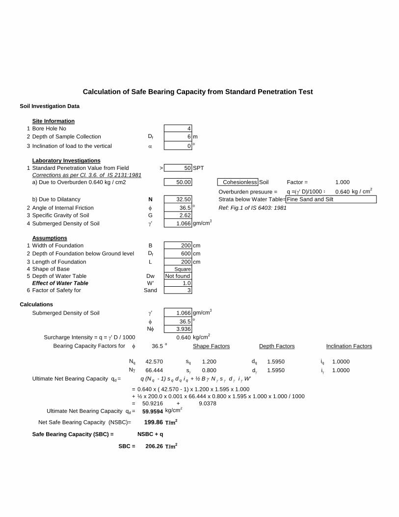
Soil Investigation Data
Site Information1 Bore Hole No 12 Depth of Sample Collection Df 6 m
3 Inclination of load to the vertical a 0 o
Laboratory Investigations1 Standard Penetration Value from Field > 50 SPT
Corrections as per Cl. 3.6. of IS 2131:1981a) Due to Overburden 0.635 kg / cm2 50.00 Cohesionless Soil Factor = 1.000
Overburden presuure = q =(g' D)/1000 = 0.635 kg / cm2
b) Due to Dilatancy N 32.502 Angle of Internal Friction f 36.5 o Ref: Fig.1 of IS 6403: 19813 Specific Gravity of Soil G 2.644 Submerged Density of Soil g' 1.058 gm/cm3
Assumptions1 Width of Foundation B 200 cm2 Depth of Foundation below Ground level Df 600 cm3 Length of Foundation L 200 cm4 Shape of Base Square5 Depth of Water Table Dw Not found
Effect of Water Table W' 1.06 Factor of Safety for Sand 3
CalculationsSubmerged Density of Soil g' 1.058 gm/cm3
f 36.5 o
Nf 3.936 Surcharge Intensity = q = g' D / 1000 0.635 kg/cm2
Bearing Capacity Factors for f 36.5 o Shape Factors Depth Factors Inclination Factors
Nq 42.570 sq 1.200 dq 1.5950 iq 1.0000Ng 66.444 sg 0.800 dg 1.5950 ig 1.0000
Ultimate Net Bearing Capacity qd = q (N q - 1) s q d q i q + ½ B g N g s g d g i g W'
= 0.635 x ( 42.570 - 1) x 1.200 x 1.595 x 1.000+ ½ x 200.0 x 0.001 x 66.444 x 0.800 x 1.595 x 1.000 x 1.000 / 1000= 50.5238 + 8.97
Ultimate Net Bearing Capacity qd = 59.4938 kg/cm2
Net Safe Bearing Capacity (NSBC)= 198.31 T/m2
Safe Bearing Capacity (SBC) = NSBC + q
SBC = 204.66 T/m2
Calculation of Safe Bearing Capacity from Standard Penetration Test
Strata below Water Table=Fine Sand and Silt

Soil Investigation Data
Site Information1 Bore Hole No 12 Depth of Sample Collection Df 7.5 m
3 Inclination of load to the vertical a 0 o
Laboratory Investigations1 Standard Penetration Value from Field > 50 SPT
Corrections as per Cl. 3.6. of IS 2131:1981a) Due to Overburden 0.784 kg / cm2 50.00 Cohesionless Soil Factor = 1.000
Overburden presuure = q =(g' D)/1000 = 0.784 kg / cm2
b) Due to Dilatancy N 32.502 Angle of Internal Friction f 36.5 o Ref: Fig.1 of IS 6403: 19813 Specific Gravity of Soil G 2.644 Submerged Density of Soil g' 1.045 gm/cm3
Assumptions1 Width of Foundation B 200 cm2 Depth of Foundation below Ground level Df 750 cm3 Length of Foundation L 200 cm4 Shape of Base Square5 Depth of Water Table Dw Not found
Effect of Water Table W' 1.06 Factor of Safety for Sand 3
CalculationsSubmerged Density of Soil g' 1.045 gm/cm3
f 36.5 o
Nf 3.936 Surcharge Intensity = q = g' D / 1000 0.784 kg/cm2
Bearing Capacity Factors for f 36.5 o Shape Factors Depth Factors Inclination Factors
Nq 42.570 sq 1.200 dq 1.7440 iq 1.0000Ng 66.444 sg 0.800 dg 1.7440 ig 1.0000
Ultimate Net Bearing Capacity qd = q (N q - 1) s q d q i q + ½ B g N g s g d g i g W'
= 0.784 x ( 42.570 - 1) x 1.200 x 1.744 x 1.000+ ½ x 200.0 x 0.001 x 66.444 x 0.800 x 1.744 x 1.000 x 1.000 / 1000= 68.2062 + 9.6874
Ultimate Net Bearing Capacity qd = 77.8936 kg/cm2
Net Safe Bearing Capacity (NSBC)= 259.65 T/m2
Safe Bearing Capacity (SBC) = NSBC + q
SBC = 267.49 T/m2
Calculation of Safe Bearing Capacity from Standard Penetration Test
Strata below Water Table=Fine Sand and Silt

Soil Investigation Data
Site Information1 Bore Hole No 12 Depth of Sample Collection Df 9 m
3 Inclination of load to the vertical a 0 o
Laboratory Investigations1 Standard Penetration Value from Field > 50 SPT
Corrections as per Cl. 3.6. of IS 2131:1981a) Due to Overburden 0.941 kg / cm2 50.00 Cohesionless Soil Factor = 1.000
Overburden presuure = q =(g' D)/1000 = 0.941 kg / cm2
b) Due to Dilatancy N 32.502 Angle of Internal Friction f 36.5 o Ref: Fig.1 of IS 6403: 19813 Specific Gravity of Soil G 2.644 Submerged Density of Soil g' 1.045 gm/cm3
Assumptions1 Width of Foundation B 200 cm2 Depth of Foundation below Ground level Df 900 cm3 Length of Foundation L 200 cm4 Shape of Base Square5 Depth of Water Table Dw Not found
Effect of Water Table W' 1.06 Factor of Safety for Sand 3
CalculationsSubmerged Density of Soil g' 1.045 gm/cm3
f 36.5 o
Nf 3.936 Surcharge Intensity = q = g' D / 1000 0.941 kg/cm2
Bearing Capacity Factors for f 36.5 o Shape Factors Depth Factors Inclination Factors
Nq 42.570 sq 1.200 dq 1.8930 iq 1.0000Ng 66.444 sg 0.800 dg 1.8930 ig 1.0000
Ultimate Net Bearing Capacity qd = q (N q - 1) s q d q i q + ½ B g N g s g d g i g W'
= 0.941 x ( 42.570 - 1) x 1.200 x 1.893 x 1.000+ ½ x 200.0 x 0.001 x 66.444 x 0.800 x 1.893 x 1.000 x 1.000 / 1000= 88.859 + 10.5151
Ultimate Net Bearing Capacity qd = 99.3741 kg/cm2
Net Safe Bearing Capacity (NSBC)= 331.25 T/m2
Safe Bearing Capacity (SBC) = NSBC + q
SBC = 340.66 T/m2
Calculation of Safe Bearing Capacity from Standard Penetration Test
Strata below Water Table=Fine Sand and Silt
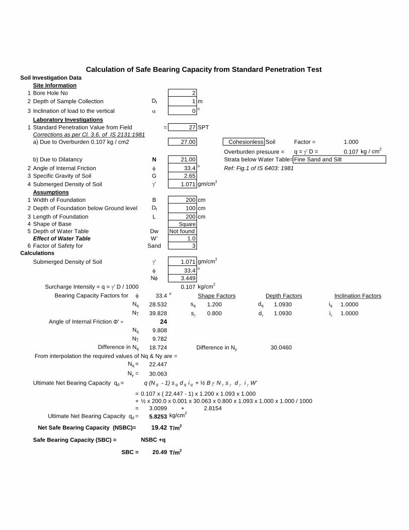
Soil Investigation DataSite Information
1 Bore Hole No 22 Depth of Sample Collection Df 1 m
3 Inclination of load to the vertical a 0 o
Laboratory Investigations1 Standard Penetration Value from Field = 27 SPT
Corrections as per Cl. 3.6. of IS 2131:1981a) Due to Overburden 0.107 kg / cm2 27.00 Cohesionless Soil Factor = 1.000
Overburden presuure = q = g' D = 0.107 kg / cm2
b) Due to Dilatancy N 21.002 Angle of Internal Friction f 33.4 o Ref: Fig.1 of IS 6403: 19813 Specific Gravity of Soil G 2.654 Submerged Density of Soil g' 1.071 gm/cm3
Assumptions1 Width of Foundation B 200 cm2 Depth of Foundation below Ground level Df 100 cm3 Length of Foundation L 200 cm4 Shape of Base Square5 Depth of Water Table Dw Not found
Effect of Water Table W' 1.06 Factor of Safety for Sand 3
CalculationsSubmerged Density of Soil g' 1.071 gm/cm3
f 33.4 o
Nf 3.449 Surcharge Intensity = q = g' D / 1000 0.107 kg/cm2
Bearing Capacity Factors for f 33.4 o Shape Factors Depth Factors Inclination FactorsNq 28.532 sq 1.200 dq 1.0930 iq 1.0000Ng 39.828 sg 0.800 dg 1.0930 ig 1.0000
Angle of Internal Friction Φ' = 24Nq 9.808Ng 9.782
Difference in Nq 18.724 30.0460 From interpolation the required values of Nq & Ny are =
Nq = 22.447Ny = 30.063
Ultimate Net Bearing Capacity qd = q (N q - 1) s q d q i q + ½ B g N g s g d g i g W'
= 0.107 x ( 22.447 - 1) x 1.200 x 1.093 x 1.000+ ½ x 200.0 x 0.001 x 30.063 x 0.800 x 1.093 x 1.000 x 1.000 / 1000= 3.0099 + 2.8154
Ultimate Net Bearing Capacity qd = 5.8253 kg/cm2
Net Safe Bearing Capacity (NSBC)= 19.42 T/m2
Safe Bearing Capacity (SBC) = NSBC +q
SBC = 20.49 T/m2
Calculation of Safe Bearing Capacity from Standard Penetration Test
Strata below Water Table=Fine Sand and Silt
Difference in Ny

Soil Investigation DataSite Information
1 Bore Hole No 22 Depth of Sample Collection Df 2 m
3 Inclination of load to the vertical a 0 o
Laboratory Investigations1 Standard Penetration Value from Field = 40 SPT
Corrections as per Cl. 3.6. of IS 2131:1981a) Due to Overburden 0.212 kg / cm2 40.00 Cohesionless Soil Factor = 1.000
Overburden presuure = q = g' D = 0.212 kg / cm2
b) Due to Dilatancy N 27.502 Angle of Internal Friction f 35.5 o Ref: Fig.1 of IS 6403: 19813 Specific Gravity of Soil G 2.654 Submerged Density of Soil g' 1.058 gm/cm3
Assumptions1 Width of Foundation B 200 cm2 Depth of Foundation below Ground level Df 200 cm3 Length of Foundation L 200 cm4 Shape of Base Square5 Depth of Water Table Dw Not found
Effect of Water Table W' 1.06 Factor of Safety for Sand 3
CalculationsSubmerged Density of Soil g' 1.058 gm/cm3
f 35.5 o
Nf 3.770 Surcharge Intensity = q = g' D / 1000 0.212 kg/cm2
Bearing Capacity Factors for f 35.5 o Shape Factors Depth Factors Inclination FactorsNq 36.390 sq 1.200 dq 1.1940 iq 1.0000Ng 54.168 sg 0.800 dg 1.1940 ig 1.0000
Angle of Internal Friction Φ' = 26Nq 12.208Ng 13.184
Difference in Nq 24.182 40.9840 From interpolation the required values of Nq & Ny are =
Nq = 34.879Ny = 51.607
Ultimate Net Bearing Capacity qd = q (N q - 1) s q d q i q + ½ B g N g s g d g i g W'
= 0.212 x ( 34.879 - 1) x 1.200 x 1.194 x 1.000+ ½ x 200.0 x 0.001 x 51.607 x 0.800 x 1.194 x 1.000 x 1.000 / 1000= 10.2908 + 5.2154
Ultimate Net Bearing Capacity qd = 15.5062 kg/cm2
Net Safe Bearing Capacity (NSBC)= 51.69 T/m2
Safe Bearing Capacity (SBC) = NSBC +q
SBC = 53.81 T/m2
Calculation of Safe Bearing Capacity from Standard Penetration Test
Strata below Water Table=Fine Sand and Silt
Difference in Ny

Soil Investigation Data
Site Information1 Bore Hole No 22 Depth of Sample Collection Df 3 m
3 Inclination of load to the vertical a 0 o
Laboratory Investigations1 Standard Penetration Value from Field > 50 SPT
Corrections as per Cl. 3.6. of IS 2131:1981a) Due to Overburden 0.317 kg / cm2 50.00 Cohesionless Soil Factor = 1.000
Overburden presuure = q =(g' D)/1000 = 0.317 kg / cm2
b) Due to Dilatancy N 32.502 Angle of Internal Friction f 36.5 o Ref: Fig.1 of IS 6403: 19813 Specific Gravity of Soil G 2.644 Submerged Density of Soil g' 1.058 gm/cm3
Assumptions1 Width of Foundation B 200 cm2 Depth of Foundation below Ground level Df 300 cm3 Length of Foundation L 200 cm4 Shape of Base Square5 Depth of Water Table Dw Not found
Effect of Water Table W' 1.06 Factor of Safety for Sand 3
CalculationsSubmerged Density of Soil g' 1.058 gm/cm3
f 36.5 o
Nf 3.936 Surcharge Intensity = q = g' D / 1000 0.317 kg/cm2
Bearing Capacity Factors for f 36.5 o Shape Factors Depth Factors Inclination Factors
Nq 42.570 sq 1.200 dq 1.2980 iq 1.0000Ng 66.444 sg 0.800 dg 1.2980 ig 1.0000
Ultimate Net Bearing Capacity qd = q (N q - 1) s q d q i q + ½ B g N g s g d g i g W'
= 0.317 x ( 42.570 - 1) x 1.200 x 1.298 x 1.000+ ½ x 200.0 x 0.001 x 66.444 x 0.800 x 1.298 x 1.000 x 1.000 / 1000= 20.5256 + 7.2997
Ultimate Net Bearing Capacity qd = 27.8253 kg/cm2
Net Safe Bearing Capacity (NSBC)= 92.75 T/m2
Safe Bearing Capacity (SBC) = NSBC + q
SBC = 95.92 T/m2
Calculation of Safe Bearing Capacity from Standard Penetration Test
Strata below Water Table=Fine Sand and Silt

Soil Investigation Data
Site Information1 Bore Hole No 22 Depth of Sample Collection Df 4.5 m
3 Inclination of load to the vertical a 0 o
Laboratory Investigations1 Standard Penetration Value from Field > 50 SPT
Corrections as per Cl. 3.6. of IS 2131:1981a) Due to Overburden 0.470 kg / cm2 50.00 Cohesionless Soil Factor = 1.000
Overburden presuure = q =(g' D)/1000 = 0.470 kg / cm2
b) Due to Dilatancy N 32.502 Angle of Internal Friction f 36.5 o Ref: Fig.1 of IS 6403: 19813 Specific Gravity of Soil G 2.624 Submerged Density of Soil g' 1.045 gm/cm3
Assumptions1 Width of Foundation B 200 cm2 Depth of Foundation below Ground level Df 450 cm3 Length of Foundation L 200 cm4 Shape of Base Square5 Depth of Water Table Dw Not found
Effect of Water Table W' 1.06 Factor of Safety for Sand 3
CalculationsSubmerged Density of Soil g' 1.045 gm/cm3
f 36.5 o
Nf 3.936 Surcharge Intensity = q = g' D / 1000 0.470 kg/cm2
Bearing Capacity Factors for f 36.5 o Shape Factors Depth Factors Inclination Factors
Nq 42.570 sq 1.200 dq 1.4460 iq 1.0000Ng 66.444 sg 0.800 dg 1.4460 ig 1.0000
Ultimate Net Bearing Capacity qd = q (N q - 1) s q d q i q + ½ B g N g s g d g i g W'
= 0.470 x ( 42.570 - 1) x 1.200 x 1.446 x 1.000+ ½ x 200.0 x 0.001 x 66.444 x 0.800 x 1.446 x 1.000 x 1.000 / 1000= 33.9022 + 8.0321
Ultimate Net Bearing Capacity qd = 41.9343 kg/cm2
Net Safe Bearing Capacity (NSBC)= 139.78 T/m2
Safe Bearing Capacity (SBC) = NSBC + q
SBC = 144.48 T/m2
Calculation of Safe Bearing Capacity from Standard Penetration Test
Strata below Water Table=Fine Sand and Silt

Soil Investigation Data
Site Information1 Bore Hole No 22 Depth of Sample Collection Df 6 m
3 Inclination of load to the vertical a 0 o
Laboratory Investigations1 Standard Penetration Value from Field > 50 SPT
Corrections as per Cl. 3.6. of IS 2131:1981a) Due to Overburden 0.627 kg / cm2 50.00 Cohesionless Soil Factor = 1.000
Overburden presuure = q =(g' D)/1000 = 0.627 kg / cm2
b) Due to Dilatancy N 32.502 Angle of Internal Friction f 36.5 o Ref: Fig.1 of IS 6403: 19813 Specific Gravity of Soil G 2.624 Submerged Density of Soil g' 1.045 gm/cm3
Assumptions1 Width of Foundation B 200 cm2 Depth of Foundation below Ground level Df 600 cm3 Length of Foundation L 200 cm4 Shape of Base Square5 Depth of Water Table Dw Not found
Effect of Water Table W' 1.06 Factor of Safety for Sand 3
CalculationsSubmerged Density of Soil g' 1.045 gm/cm3
f 36.5 o
Nf 3.936 Surcharge Intensity = q = g' D / 1000 0.627 kg/cm2
Bearing Capacity Factors for f 36.5 o Shape Factors Depth Factors Inclination Factors
Nq 42.570 sq 1.200 dq 1.5950 iq 1.0000Ng 66.444 sg 0.800 dg 1.5950 ig 1.0000
Ultimate Net Bearing Capacity qd = q (N q - 1) s q d q i q + ½ B g N g s g d g i g W'
= 0.627 x ( 42.570 - 1) x 1.200 x 1.595 x 1.000+ ½ x 200.0 x 0.001 x 66.444 x 0.800 x 1.595 x 1.000 x 1.000 / 1000= 49.8872 + 8.8598
Ultimate Net Bearing Capacity qd = 58.7470 kg/cm2
Net Safe Bearing Capacity (NSBC)= 195.82 T/m2
Safe Bearing Capacity (SBC) = NSBC + q
SBC = 202.09 T/m2
Calculation of Safe Bearing Capacity from Standard Penetration Test
Strata below Water Table=Fine Sand and Silt

Soil Investigation Data
Site Information1 Bore Hole No 32 Depth of Sample Collection Df 1 m
3 Inclination of load to the vertical a 0 o
Laboratory Investigations1 Standard Penetration Value from Field > 50 SPT
Corrections as per Cl. 3.6. of IS 2131:1981a) Due to Overburden 0.106 kg / cm2 50.00 Cohesionless Soil Factor = 1.000
Overburden presuure = q =(g' D)/1000 = 0.106 kg / cm2
b) Due to Dilatancy N 32.502 Angle of Internal Friction f 36.5 o Ref: Fig.1 of IS 6403: 19813 Specific Gravity of Soil G 2.654 Submerged Density of Soil g' 1.058 gm/cm3
Assumptions1 Width of Foundation B 200 cm2 Depth of Foundation below Ground level Df 100 cm3 Length of Foundation L 200 cm4 Shape of Base Square5 Depth of Water Table Dw Not found
Effect of Water Table W' 1.06 Factor of Safety for Sand 3
CalculationsSubmerged Density of Soil g' 1.058 gm/cm3
f 36.5 o
Nf 3.936 Surcharge Intensity = q = g' D / 1000 0.106 kg/cm2
Bearing Capacity Factors for f 36.5 o Shape Factors Depth Factors Inclination Factors
Nq 42.570 sq 1.200 dq 1.0990 iq 1.0000Ng 66.444 sg 0.800 dg 1.0990 ig 1.0000
Ultimate Net Bearing Capacity qd = q (N q - 1) s q d q i q + ½ B g N g s g d g i g W'
= 0.106 x ( 42.570 - 1) x 1.200 x 1.099 x 1.000+ ½ x 200.0 x 0.001 x 66.444 x 0.800 x 1.099 x 1.000 x 1.000 / 1000= 5.8112 + 6.1806
Ultimate Net Bearing Capacity qd = 11.9918 kg/cm2
Net Safe Bearing Capacity (NSBC)= 39.97 T/m2
Safe Bearing Capacity (SBC) = NSBC + q
SBC = 41.03 T/m2
Calculation of Safe Bearing Capacity from Standard Penetration Test
Strata below Water Table=Fine Sand and Silt

Soil Investigation Data
Site Information1 Bore Hole No 32 Depth of Sample Collection Df 2 m
3 Inclination of load to the vertical a 0 o
Laboratory Investigations1 Standard Penetration Value from Field > 50 SPT
Corrections as per Cl. 3.6. of IS 2131:1981a) Due to Overburden 0.209 kg / cm2 50.00 Cohesionless Soil Factor = 1.000
Overburden presuure = q =(g' D)/1000 = 0.209 kg / cm2
b) Due to Dilatancy N 32.502 Angle of Internal Friction f 36.5 o Ref: Fig.1 of IS 6403: 19813 Specific Gravity of Soil G 2.624 Submerged Density of Soil g' 1.045 gm/cm3
Assumptions1 Width of Foundation B 200 cm2 Depth of Foundation below Ground level Df 200 cm3 Length of Foundation L 200 cm4 Shape of Base Square5 Depth of Water Table Dw Not found
Effect of Water Table W' 1.06 Factor of Safety for Sand 3
CalculationsSubmerged Density of Soil g' 1.045 gm/cm3
f 36.5 o
Nf 3.936 Surcharge Intensity = q = g' D / 1000 0.209 kg/cm2
Bearing Capacity Factors for f 36.5 o Shape Factors Depth Factors Inclination Factors
Nq 42.570 sq 1.200 dq 1.1980 iq 1.0000Ng 66.444 sg 0.800 dg 1.1980 ig 1.0000
Ultimate Net Bearing Capacity qd = q (N q - 1) s q d q i q + ½ B g N g s g d g i g W'
= 0.209 x ( 42.570 - 1) x 1.200 x 1.198 x 1.000+ ½ x 200.0 x 0.001 x 66.444 x 0.800 x 1.198 x 1.000 x 1.000 / 1000= 12.4901 + 6.6546
Ultimate Net Bearing Capacity qd = 19.1447 kg/cm2
Net Safe Bearing Capacity (NSBC)= 63.82 T/m2
Safe Bearing Capacity (SBC) = NSBC + q
SBC = 65.91 T/m2
Calculation of Safe Bearing Capacity from Standard Penetration Test
Strata below Water Table=Fine Sand and Silt

Soil Investigation Data
Site Information1 Bore Hole No 32 Depth of Sample Collection Df 3 m
3 Inclination of load to the vertical a 0 o
Laboratory Investigations1 Standard Penetration Value from Field > 50 SPT
Corrections as per Cl. 3.6. of IS 2131:1981a) Due to Overburden 0.314 kg / cm2 50.00 Cohesionless Soil Factor = 1.000
Overburden presuure = q =(g' D)/1000 = 0.314 kg / cm2
b) Due to Dilatancy N 32.502 Angle of Internal Friction f 36.5 o Ref: Fig.1 of IS 6403: 19813 Specific Gravity of Soil G 2.624 Submerged Density of Soil g' 1.045 gm/cm3
Assumptions1 Width of Foundation B 200 cm2 Depth of Foundation below Ground level Df 300 cm3 Length of Foundation L 200 cm4 Shape of Base Square5 Depth of Water Table Dw Not found
Effect of Water Table W' 1.06 Factor of Safety for Sand 3
CalculationsSubmerged Density of Soil g' 1.045 gm/cm3
f 36.5 o
Nf 3.936 Surcharge Intensity = q = g' D / 1000 0.314 kg/cm2
Bearing Capacity Factors for f 36.5 o Shape Factors Depth Factors Inclination Factors
Nq 42.570 sq 1.200 dq 1.2980 iq 1.0000Ng 66.444 sg 0.800 dg 1.2980 ig 1.0000
Ultimate Net Bearing Capacity qd = q (N q - 1) s q d q i q + ½ B g N g s g d g i g W'
= 0.314 x ( 42.570 - 1) x 1.200 x 1.298 x 1.000+ ½ x 200.0 x 0.001 x 66.444 x 0.800 x 1.298 x 1.000 x 1.000 / 1000= 20.3313 + 7.21
Ultimate Net Bearing Capacity qd = 27.5413 kg/cm2
Net Safe Bearing Capacity (NSBC)= 91.8 T/m2
Safe Bearing Capacity (SBC) = NSBC + q
SBC = 94.94 T/m2
Calculation of Safe Bearing Capacity from Standard Penetration Test
Strata below Water Table=Fine Sand and Silt

Soil Investigation Data
Site Information1 Bore Hole No 32 Depth of Sample Collection Df 4.5 m
3 Inclination of load to the vertical a 0 o
Laboratory Investigations1 Standard Penetration Value from Field > 50 SPT
Corrections as per Cl. 3.6. of IS 2131:1981a) Due to Overburden 0.473 kg / cm2 50.00 Cohesionless Soil Factor = 1.000
Overburden presuure = q =(g' D)/1000 = 0.473 kg / cm2
b) Due to Dilatancy N 32.502 Angle of Internal Friction f 36.5 o Ref: Fig.1 of IS 6403: 19813 Specific Gravity of Soil G 2.624 Submerged Density of Soil g' 1.052 gm/cm3
Assumptions1 Width of Foundation B 200 cm2 Depth of Foundation below Ground level Df 450 cm3 Length of Foundation L 200 cm4 Shape of Base Square5 Depth of Water Table Dw Not found
Effect of Water Table W' 1.06 Factor of Safety for Sand 3
CalculationsSubmerged Density of Soil g' 1.052 gm/cm3
f 36.5 o
Nf 3.936 Surcharge Intensity = q = g' D / 1000 0.473 kg/cm2
Bearing Capacity Factors for f 36.5 o Shape Factors Depth Factors Inclination Factors
Nq 42.570 sq 1.200 dq 1.4460 iq 1.0000Ng 66.444 sg 0.800 dg 1.4460 ig 1.0000
Ultimate Net Bearing Capacity qd = q (N q - 1) s q d q i q + ½ B g N g s g d g i g W'
= 0.473 x ( 42.570 - 1) x 1.200 x 1.446 x 1.000+ ½ x 200.0 x 0.001 x 66.444 x 0.800 x 1.446 x 1.000 x 1.000 / 1000= 34.1186 + 8.0859
Ultimate Net Bearing Capacity qd = 42.2045 kg/cm2
Net Safe Bearing Capacity (NSBC)= 140.68 T/m2
Safe Bearing Capacity (SBC) = NSBC + q
SBC = 145.41 T/m2
Calculation of Safe Bearing Capacity from Standard Penetration Test
Strata below Water Table=Fine Sand and Silt

Soil Investigation Data
Site Information1 Bore Hole No 32 Depth of Sample Collection Df 6 m
3 Inclination of load to the vertical a 0 o
Laboratory Investigations1 Standard Penetration Value from Field > 50 SPT
Corrections as per Cl. 3.6. of IS 2131:1981a) Due to Overburden 0.631 kg / cm2 50.00 Cohesionless Soil Factor = 1.000
Overburden presuure = q =(g' D)/1000 = 0.631 kg / cm2
b) Due to Dilatancy N 32.502 Angle of Internal Friction f 36.5 o Ref: Fig.1 of IS 6403: 19813 Specific Gravity of Soil G 2.624 Submerged Density of Soil g' 1.052 gm/cm3
Assumptions1 Width of Foundation B 200 cm2 Depth of Foundation below Ground level Df 600 cm3 Length of Foundation L 200 cm4 Shape of Base Square5 Depth of Water Table Dw Not found
Effect of Water Table W' 1.06 Factor of Safety for Sand 3
CalculationsSubmerged Density of Soil g' 1.052 gm/cm3
f 36.5 o
Nf 3.936 Surcharge Intensity = q = g' D / 1000 0.631 kg/cm2
Bearing Capacity Factors for f 36.5 o Shape Factors Depth Factors Inclination Factors
Nq 42.570 sq 1.200 dq 1.5950 iq 1.0000Ng 66.444 sg 0.800 dg 1.5950 ig 1.0000
Ultimate Net Bearing Capacity qd = q (N q - 1) s q d q i q + ½ B g N g s g d g i g W'
= 0.631 x ( 42.570 - 1) x 1.200 x 1.595 x 1.000+ ½ x 200.0 x 0.001 x 66.444 x 0.800 x 1.595 x 1.000 x 1.000 / 1000= 50.2055 + 8.9191
Ultimate Net Bearing Capacity qd = 59.1246 kg/cm2
Net Safe Bearing Capacity (NSBC)= 197.08 T/m2
Safe Bearing Capacity (SBC) = NSBC + q
SBC = 203.39 T/m2
Calculation of Safe Bearing Capacity from Standard Penetration Test
Strata below Water Table=Fine Sand and Silt

Soil Investigation Data
Site Information1 Bore Hole No 42 Depth of Sample Collection Df 1 m
3 Inclination of load to the vertical a 0 o
Laboratory Investigations1 Standard Penetration Value from Field > 50 SPT
Corrections as per Cl. 3.6. of IS 2131:1981a) Due to Overburden 0.103 kg / cm2 50.00 Cohesionless Soil Factor = 1.000
Overburden presuure = q =(g' D)/1000 = 0.103 kg / cm2
b) Due to Dilatancy N 32.502 Angle of Internal Friction f 36.5 o Ref: Fig.1 of IS 6403: 19813 Specific Gravity of Soil G 2.624 Submerged Density of Soil g' 1.025 gm/cm3
Assumptions1 Width of Foundation B 200 cm2 Depth of Foundation below Ground level Df 100 cm3 Length of Foundation L 200 cm4 Shape of Base Square5 Depth of Water Table Dw Not found
Effect of Water Table W' 1.06 Factor of Safety for Sand 3
CalculationsSubmerged Density of Soil g' 1.025 gm/cm3
f 36.5 o
Nf 3.936 Surcharge Intensity = q = g' D / 1000 0.103 kg/cm2
Bearing Capacity Factors for f 36.5 o Shape Factors Depth Factors Inclination Factors
Nq 42.570 sq 1.200 dq 1.0990 iq 1.0000Ng 66.444 sg 0.800 dg 1.0990 ig 1.0000
Ultimate Net Bearing Capacity qd = q (N q - 1) s q d q i q + ½ B g N g s g d g i g W'
= 0.103 x ( 42.570 - 1) x 1.200 x 1.099 x 1.000+ ½ x 200.0 x 0.001 x 66.444 x 0.800 x 1.099 x 1.000 x 1.000 / 1000= 5.6467 + 5.9878
Ultimate Net Bearing Capacity qd = 11.6345 kg/cm2
Net Safe Bearing Capacity (NSBC)= 38.78 T/m2
Safe Bearing Capacity (SBC) = NSBC + q
SBC = 39.81 T/m2
Calculation of Safe Bearing Capacity from Standard Penetration Test
Strata below Water Table=Fine Sand and Silt

Soil Investigation Data
Site Information1 Bore Hole No 42 Depth of Sample Collection Df 2 m
3 Inclination of load to the vertical a 0 o
Laboratory Investigations1 Standard Penetration Value from Field > 50 SPT
Corrections as per Cl. 3.6. of IS 2131:1981a) Due to Overburden 0.212 kg / cm2 50.00 Cohesionless Soil Factor = 1.000
Overburden presuure = q =(g' D)/1000 = 0.212 kg / cm2
b) Due to Dilatancy N 32.502 Angle of Internal Friction f 36.5 o Ref: Fig.1 of IS 6403: 19813 Specific Gravity of Soil G 2.624 Submerged Density of Soil g' 1.059 gm/cm3
Assumptions1 Width of Foundation B 200 cm2 Depth of Foundation below Ground level Df 200 cm3 Length of Foundation L 200 cm4 Shape of Base Square5 Depth of Water Table Dw Not found
Effect of Water Table W' 1.06 Factor of Safety for Sand 3
CalculationsSubmerged Density of Soil g' 1.059 gm/cm3
f 36.5 o
Nf 3.936 Surcharge Intensity = q = g' D / 1000 0.212 kg/cm2
Bearing Capacity Factors for f 36.5 o Shape Factors Depth Factors Inclination Factors
Nq 42.570 sq 1.200 dq 1.1980 iq 1.0000Ng 66.444 sg 0.800 dg 1.1980 ig 1.0000
Ultimate Net Bearing Capacity qd = q (N q - 1) s q d q i q + ½ B g N g s g d g i g W'
= 0.212 x ( 42.570 - 1) x 1.200 x 1.198 x 1.000+ ½ x 200.0 x 0.001 x 66.444 x 0.800 x 1.198 x 1.000 x 1.000 / 1000= 12.6693 + 6.7437
Ultimate Net Bearing Capacity qd = 19.4130 kg/cm2
Net Safe Bearing Capacity (NSBC)= 64.71 T/m2
Safe Bearing Capacity (SBC) = NSBC + q
SBC = 66.83 T/m2
Calculation of Safe Bearing Capacity from Standard Penetration Test
Strata below Water Table=Fine Sand and Silt

Soil Investigation Data
Site Information1 Bore Hole No 42 Depth of Sample Collection Df 3 m
3 Inclination of load to the vertical a 0 o
Laboratory Investigations1 Standard Penetration Value from Field > 50 SPT
Corrections as per Cl. 3.6. of IS 2131:1981a) Due to Overburden 0.318 kg / cm2 50.00 Cohesionless Soil Factor = 1.000
Overburden presuure = q =(g' D)/1000 = 0.318 kg / cm2
b) Due to Dilatancy N 32.502 Angle of Internal Friction f 36.5 o Ref: Fig.1 of IS 6403: 19813 Specific Gravity of Soil G 2.624 Submerged Density of Soil g' 1.059 gm/cm3
Assumptions1 Width of Foundation B 200 cm2 Depth of Foundation below Ground level Df 300 cm3 Length of Foundation L 200 cm4 Shape of Base Square5 Depth of Water Table Dw Not found
Effect of Water Table W' 1.06 Factor of Safety for Sand 3
CalculationsSubmerged Density of Soil g' 1.059 gm/cm3
f 36.5 o
Nf 3.936 Surcharge Intensity = q = g' D / 1000 0.318 kg/cm2
Bearing Capacity Factors for f 36.5 o Shape Factors Depth Factors Inclination Factors
Nq 42.570 sq 1.200 dq 1.2980 iq 1.0000Ng 66.444 sg 0.800 dg 1.2980 ig 1.0000
Ultimate Net Bearing Capacity qd = q (N q - 1) s q d q i q + ½ B g N g s g d g i g W'
= 0.318 x ( 42.570 - 1) x 1.200 x 1.298 x 1.000+ ½ x 200.0 x 0.001 x 66.444 x 0.800 x 1.298 x 1.000 x 1.000 / 1000= 20.5903 + 7.3066
Ultimate Net Bearing Capacity qd = 27.8969 kg/cm2
Net Safe Bearing Capacity (NSBC)= 92.99 T/m2
Safe Bearing Capacity (SBC) = NSBC + q
SBC = 96.17 T/m2
Calculation of Safe Bearing Capacity from Standard Penetration Test
Strata below Water Table=Fine Sand and Silt

Soil Investigation Data
Site Information1 Bore Hole No 42 Depth of Sample Collection Df 4.5 m
3 Inclination of load to the vertical a 0 o
Laboratory Investigations1 Standard Penetration Value from Field > 50 SPT
Corrections as per Cl. 3.6. of IS 2131:1981a) Due to Overburden 0.477 kg / cm2 50.00 Cohesionless Soil Factor = 1.000
Overburden presuure = q =(g' D)/1000 = 0.477 kg / cm2
b) Due to Dilatancy N 32.502 Angle of Internal Friction f 36.5 o Ref: Fig.1 of IS 6403: 19813 Specific Gravity of Soil G 2.624 Submerged Density of Soil g' 1.059 gm/cm3
Assumptions1 Width of Foundation B 200 cm2 Depth of Foundation below Ground level Df 450 cm3 Length of Foundation L 200 cm4 Shape of Base Square5 Depth of Water Table Dw Not found
Effect of Water Table W' 1.06 Factor of Safety for Sand 3
CalculationsSubmerged Density of Soil g' 1.059 gm/cm3
f 36.5 o
Nf 3.936 Surcharge Intensity = q = g' D / 1000 0.477 kg/cm2
Bearing Capacity Factors for f 36.5 o Shape Factors Depth Factors Inclination Factors
Nq 42.570 sq 1.200 dq 1.4460 iq 1.0000Ng 66.444 sg 0.800 dg 1.4460 ig 1.0000
Ultimate Net Bearing Capacity qd = q (N q - 1) s q d q i q + ½ B g N g s g d g i g W'
= 0.477 x ( 42.570 - 1) x 1.200 x 1.446 x 1.000+ ½ x 200.0 x 0.001 x 66.444 x 0.800 x 1.446 x 1.000 x 1.000 / 1000= 34.4071 + 8.1397
Ultimate Net Bearing Capacity qd = 42.5468 kg/cm2
Net Safe Bearing Capacity (NSBC)= 141.82 T/m2
Safe Bearing Capacity (SBC) = NSBC + q
SBC = 146.59 T/m2
Calculation of Safe Bearing Capacity from Standard Penetration Test
Strata below Water Table=Fine Sand and Silt
Soil Investigation Data
Site Information1 Bore Hole No 42 Depth of Sample Collection Df 6 m
3 Inclination of load to the vertical a 0 o
Laboratory Investigations1 Standard Penetration Value from Field > 50 SPT
Corrections as per Cl. 3.6. of IS 2131:1981a) Due to Overburden 0.640 kg / cm2 50.00 Cohesionless Soil Factor = 1.000
Overburden presuure = q =(g' D)/1000 = 0.640 kg / cm2
b) Due to Dilatancy N 32.502 Angle of Internal Friction f 36.5 o Ref: Fig.1 of IS 6403: 19813 Specific Gravity of Soil G 2.624 Submerged Density of Soil g' 1.066 gm/cm3
Assumptions1 Width of Foundation B 200 cm2 Depth of Foundation below Ground level Df 600 cm3 Length of Foundation L 200 cm4 Shape of Base Square5 Depth of Water Table Dw Not found
Effect of Water Table W' 1.06 Factor of Safety for Sand 3
CalculationsSubmerged Density of Soil g' 1.066 gm/cm3
f 36.5 o
Nf 3.936 Surcharge Intensity = q = g' D / 1000 0.640 kg/cm2
Bearing Capacity Factors for f 36.5 o Shape Factors Depth Factors Inclination Factors
Nq 42.570 sq 1.200 dq 1.5950 iq 1.0000Ng 66.444 sg 0.800 dg 1.5950 ig 1.0000
Ultimate Net Bearing Capacity qd = q (N q - 1) s q d q i q + ½ B g N g s g d g i g W'
= 0.640 x ( 42.570 - 1) x 1.200 x 1.595 x 1.000+ ½ x 200.0 x 0.001 x 66.444 x 0.800 x 1.595 x 1.000 x 1.000 / 1000= 50.9216 + 9.0378
Ultimate Net Bearing Capacity qd = 59.9594 kg/cm2
Net Safe Bearing Capacity (NSBC)= 199.86 T/m2
Safe Bearing Capacity (SBC) = NSBC + q
SBC = 206.26 T/m2
Calculation of Safe Bearing Capacity from Standard Penetration Test
Strata below Water Table=Fine Sand and Silt
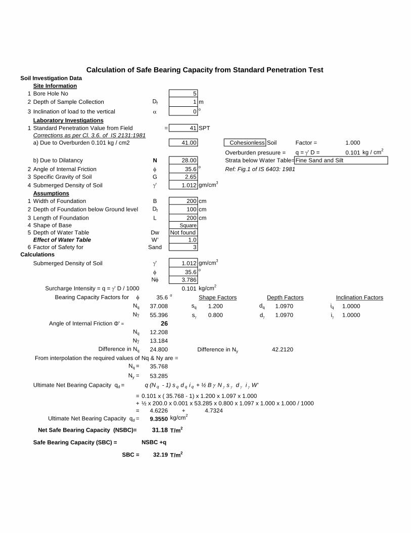
Soil Investigation DataSite Information
1 Bore Hole No 52 Depth of Sample Collection Df 1 m
3 Inclination of load to the vertical a 0 o
Laboratory Investigations1 Standard Penetration Value from Field = 41 SPT
Corrections as per Cl. 3.6. of IS 2131:1981a) Due to Overburden 0.101 kg / cm2 41.00 Cohesionless Soil Factor = 1.000
Overburden presuure = q = g' D = 0.101 kg / cm2
b) Due to Dilatancy N 28.002 Angle of Internal Friction f 35.6 o Ref: Fig.1 of IS 6403: 19813 Specific Gravity of Soil G 2.654 Submerged Density of Soil g' 1.012 gm/cm3
Assumptions1 Width of Foundation B 200 cm2 Depth of Foundation below Ground level Df 100 cm3 Length of Foundation L 200 cm4 Shape of Base Square5 Depth of Water Table Dw Not found
Effect of Water Table W' 1.06 Factor of Safety for Sand 3
CalculationsSubmerged Density of Soil g' 1.012 gm/cm3
f 35.6 o
Nf 3.786 Surcharge Intensity = q = g' D / 1000 0.101 kg/cm2
Bearing Capacity Factors for f 35.6 o Shape Factors Depth Factors Inclination FactorsNq 37.008 sq 1.200 dq 1.0970 iq 1.0000Ng 55.396 sg 0.800 dg 1.0970 ig 1.0000
Angle of Internal Friction Φ' = 26Nq 12.208Ng 13.184
Difference in Nq 24.800 42.2120 From interpolation the required values of Nq & Ny are =
Nq = 35.768Ny = 53.285
Ultimate Net Bearing Capacity qd = q (N q - 1) s q d q i q + ½ B g N g s g d g i g W'
= 0.101 x ( 35.768 - 1) x 1.200 x 1.097 x 1.000+ ½ x 200.0 x 0.001 x 53.285 x 0.800 x 1.097 x 1.000 x 1.000 / 1000= 4.6226 + 4.7324
Ultimate Net Bearing Capacity qd = 9.3550 kg/cm2
Net Safe Bearing Capacity (NSBC)= 31.18 T/m2
Safe Bearing Capacity (SBC) = NSBC +q
SBC = 32.19 T/m2
Calculation of Safe Bearing Capacity from Standard Penetration Test
Strata below Water Table=Fine Sand and Silt
Difference in Ny

Soil Investigation Data
Site Information1 Bore Hole No 52 Depth of Sample Collection Df 2 m
3 Inclination of load to the vertical a 0 o
Laboratory Investigations1 Standard Penetration Value from Field > 50 SPT
Corrections as per Cl. 3.6. of IS 2131:1981a) Due to Overburden 0.210 kg / cm2 50.00 Cohesionless Soil Factor = 1.000
Overburden presuure = q =(g' D)/1000 = 0.210 kg / cm2
b) Due to Dilatancy N 32.502 Angle of Internal Friction f 36.5 o Ref: Fig.1 of IS 6403: 19813 Specific Gravity of Soil G 2.654 Submerged Density of Soil g' 1.051 gm/cm3
Assumptions1 Width of Foundation B 200 cm2 Depth of Foundation below Ground level Df 200 cm3 Length of Foundation L 200 cm4 Shape of Base Square5 Depth of Water Table Dw Not found
Effect of Water Table W' 1.06 Factor of Safety for Sand 3
CalculationsSubmerged Density of Soil g' 1.051 gm/cm3
f 36.5 o
Nf 3.936 Surcharge Intensity = q = g' D / 1000 0.210 kg/cm2
Bearing Capacity Factors for f 36.5 o Shape Factors Depth Factors Inclination Factors
Nq 42.570 sq 1.200 dq 1.1980 iq 1.0000Ng 66.444 sg 0.800 dg 1.1980 ig 1.0000
Ultimate Net Bearing Capacity qd = q (N q - 1) s q d q i q + ½ B g N g s g d g i g W'
= 0.210 x ( 42.570 - 1) x 1.200 x 1.198 x 1.000+ ½ x 200.0 x 0.001 x 66.444 x 0.800 x 1.198 x 1.000 x 1.000 / 1000= 12.5498 + 6.6928
Ultimate Net Bearing Capacity qd = 19.2426 kg/cm2
Net Safe Bearing Capacity (NSBC)= 64.14 T/m2
Safe Bearing Capacity (SBC) = NSBC + q
SBC = 66.24 T/m2
Calculation of Safe Bearing Capacity from Standard Penetration Test
Strata below Water Table=Fine Sand and Silt

Soil Investigation Data
Site Information1 Bore Hole No 52 Depth of Sample Collection Df 3 m
3 Inclination of load to the vertical a 0 o
Laboratory Investigations1 Standard Penetration Value from Field > 50 SPT
Corrections as per Cl. 3.6. of IS 2131:1981a) Due to Overburden 0.326 kg / cm2 50.00 Cohesionless Soil Factor = 1.000
Overburden presuure = q =(g' D)/1000 = 0.326 kg / cm2
b) Due to Dilatancy N 32.502 Angle of Internal Friction f 36.5 o Ref: Fig.1 of IS 6403: 19813 Specific Gravity of Soil G 2.644 Submerged Density of Soil g' 1.086 gm/cm3
Assumptions1 Width of Foundation B 200 cm2 Depth of Foundation below Ground level Df 300 cm3 Length of Foundation L 200 cm4 Shape of Base Square5 Depth of Water Table Dw Not found
Effect of Water Table W' 1.06 Factor of Safety for Sand 3
CalculationsSubmerged Density of Soil g' 1.086 gm/cm3
f 36.5 o
Nf 3.936 Surcharge Intensity = q = g' D / 1000 0.326 kg/cm2
Bearing Capacity Factors for f 36.5 o Shape Factors Depth Factors Inclination Factors
Nq 42.570 sq 1.200 dq 1.2980 iq 1.0000Ng 66.444 sg 0.800 dg 1.2980 ig 1.0000
Ultimate Net Bearing Capacity qd = q (N q - 1) s q d q i q + ½ B g N g s g d g i g W'
= 0.326 x ( 42.570 - 1) x 1.200 x 1.298 x 1.000+ ½ x 200.0 x 0.001 x 66.444 x 0.800 x 1.298 x 1.000 x 1.000 / 1000= 21.1083 + 7.4929
Ultimate Net Bearing Capacity qd = 28.6012 kg/cm2
Net Safe Bearing Capacity (NSBC)= 95.34 T/m2
Safe Bearing Capacity (SBC) = NSBC + q
SBC = 98.6 T/m2
Calculation of Safe Bearing Capacity from Standard Penetration Test
Strata below Water Table=Fine Sand and Silt

BH-11 mt.
32.5
7.5 mm
0.5
15.00 mm
Due to imposed load = NSBC = 37.450 t/m2
Settlement from graph = 56.18 mm
Depth factor = 0.85
Sfd = Sf x Depth factor = 47.75 mm
0.8
38.2 mm ( Say 38 mm )
Corrected Settlement
Rigidity factor =
Final settlement ( S ) =
CALCULATION OF SETTLEMENT OF FOUNDATION AS PER IS:8009 (Part -I)-1976
Depth of foundation
Corrected N Value
From graph As pr IS: 8009-1976
Effect of water table

BH-12 mt.
32.5
7.5 mm
0.5
15.00 mm
Due to imposed load = NSBC = 61.070 t/m2
Settlement from graph = 91.61 mm
Depth factor = 0.725
Sfd = Sf x Depth factor = 66.41 mm
0.8
53.1 mm ( Say 53 mm )
Effect of water table
Corrected Settlement
Rigidity factor =
Final settlement ( S ) =
CALCULATION OF SETTLEMENT OF FOUNDATION AS PER IS:8009 (Part -I)-1976
Depth of foundation
Corrected N Value
From graph As pr IS: 8009-1976

BH-13 mt.
32.5
7.5 mm
0.5
15.00 mm
Due to imposed load = NSBC = 93.560 t/m2
Settlement from graph = 140.34 mm
Depth factor = 0.66
Sfd = Sf x Depth factor = 92.62 mm
0.8
74.1 mm ( Say 74 mm )
Effect of water table
Corrected Settlement
Rigidity factor =
Final settlement ( S ) =
CALCULATION OF SETTLEMENT OF FOUNDATION AS PER IS:8009 (Part -I)-1976
Depth of foundation
Corrected N Value
From graph As pr IS: 8009-1976
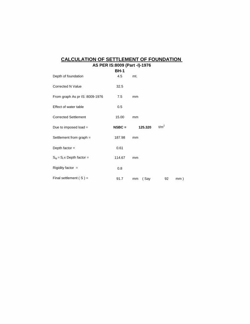
BH-14.5 mt.
32.5
7.5 mm
0.5
15.00 mm
Due to imposed load = NSBC = 125.320 t/m2
Settlement from graph = 187.98 mm
Depth factor = 0.61
Sfd = Sf x Depth factor = 114.67 mm
0.8
91.7 mm ( Say 92 mm )
Effect of water table
Corrected Settlement
Rigidity factor =
Final settlement ( S ) =
CALCULATION OF SETTLEMENT OF FOUNDATION AS PER IS:8009 (Part -I)-1976
Depth of foundation
Corrected N Value
From graph As pr IS: 8009-1976

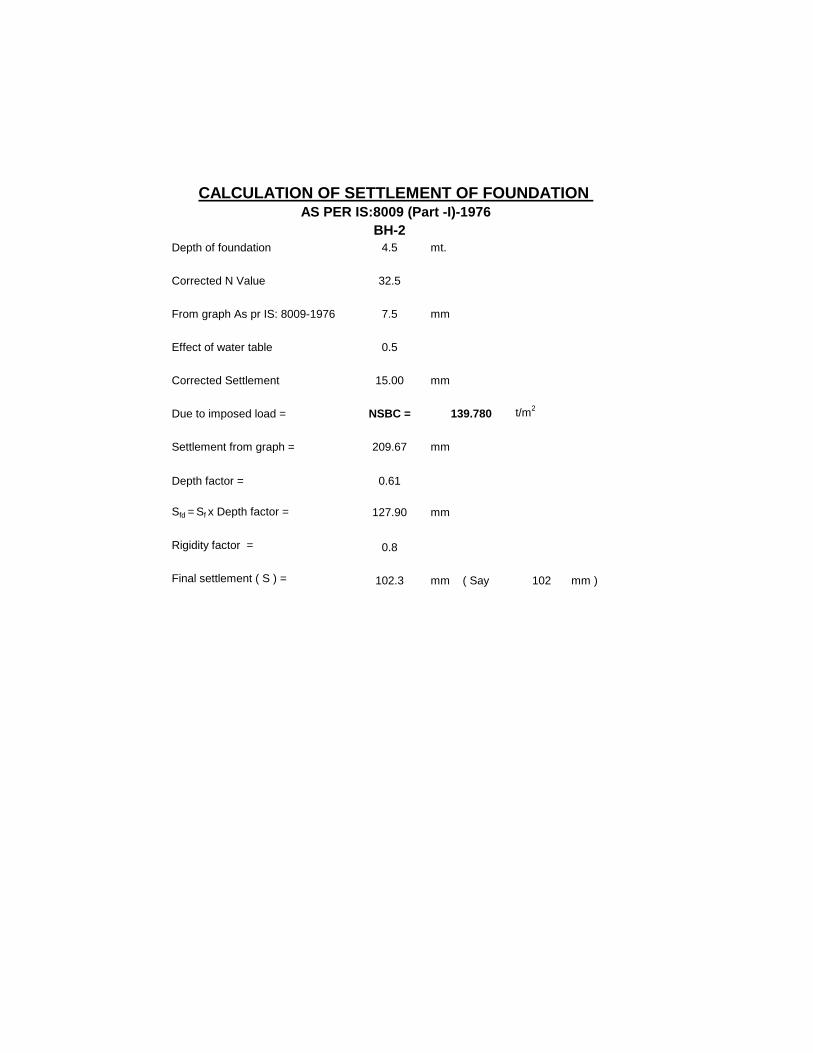
BH-16 mt.
32.5
7.5 mm
0.5
15.00 mm
Due to imposed load = NSBC = 198.310 t/m2
Settlement from graph = 297.47 mm
Depth factor = 0.58
Sfd = Sf x Depth factor = 172.53 mm
0.8
138.0 mm ( Say 138 mm )
Effect of water table
Corrected Settlement
Rigidity factor =
Final settlement ( S ) =
CALCULATION OF SETTLEMENT OF FOUNDATION AS PER IS:8009 (Part -I)-1976
Depth of foundation
Corrected N Value
From graph As pr IS: 8009-1976

BH-17.5 mt.
32.5
7.5 mm
0.5
15.00 mm
Due to imposed load = NSBC = 259.650 t/m2
Settlement from graph = 389.48 mm
Depth factor = 0.563
Sfd = Sf x Depth factor = 219.27 mm
0.8
175.4 mm ( Say 175 mm )
CALCULATION OF SETTLEMENT OF FOUNDATION AS PER IS:8009 (Part -I)-1976
Depth of foundation
Corrected N Value
From graph As pr IS: 8009-1976
Effect of water table
Corrected Settlement
Rigidity factor =
Final settlement ( S ) =

BH-19 mt.
32.5
7.5 mm
0.5
15.00 mm
Due to imposed load = NSBC = 331.250 t/m2
Settlement from graph = 496.88 mm
Depth factor = 0.56
Sfd = Sf x Depth factor = 278.25 mm
0.8
222.6 mm ( Say 223 mm )
CALCULATION OF SETTLEMENT OF FOUNDATION AS PER IS:8009 (Part -I)-1976
Depth of foundation
Corrected N Value
From graph As pr IS: 8009-1976
Effect of water table
Corrected Settlement
Rigidity factor =
Final settlement ( S ) =

BH-21 mt.
21
13.5 mm
0.5
27.00 mm
Due to imposed load = NSBC = 19.420 t/m2
Settlement from graph = 52.43 mm
Depth factor = 0.85
Sfd = Sf x Depth factor = 44.57 mm
0.8
35.7 mm ( Say 36 mm )
Effect of water table
Corrected Settlement
Rigidity factor =
Final settlement ( S ) =
CALCULATION OF SETTLEMENT OF FOUNDATION AS PER IS:8009 (Part -I)-1976
Depth of foundation
Corrected N Value
From graph As pr IS: 8009-1976

BH-22 mt.
27.5
9 mm
0.5
18.00 mm
Due to imposed load = NSBC = 51.690 t/m2
Settlement from graph = 93.04 mm
Depth factor = 0.725
Sfd = Sf x Depth factor = 67.46 mm
0.8
54.0 mm ( Say 54 mm )
Effect of water table
Corrected Settlement
Rigidity factor =
Final settlement ( S ) =
CALCULATION OF SETTLEMENT OF FOUNDATION AS PER IS:8009 (Part -I)-1976
Depth of foundation
Corrected N Value
From graph As pr IS: 8009-1976

BH-23 mt.
32.5
7.5 mm
0.5
15.00 mm
Due to imposed load = NSBC = 92.750 t/m2
Settlement from graph = 139.13 mm
Depth factor = 0.66
Sfd = Sf x Depth factor = 91.82 mm
0.8
73.5 mm ( Say 73 mm )
Effect of water table
Corrected Settlement
Rigidity factor =
Final settlement ( S ) =
CALCULATION OF SETTLEMENT OF FOUNDATION AS PER IS:8009 (Part -I)-1976
Depth of foundation
Corrected N Value
From graph As pr IS: 8009-1976
BH-24.5 mt.
32.5
7.5 mm
0.5
15.00 mm
Due to imposed load = NSBC = 139.780 t/m2
Settlement from graph = 209.67 mm
Depth factor = 0.61
Sfd = Sf x Depth factor = 127.90 mm
0.8
102.3 mm ( Say 102 mm )
Effect of water table
Corrected Settlement
Rigidity factor =
Final settlement ( S ) =
CALCULATION OF SETTLEMENT OF FOUNDATION AS PER IS:8009 (Part -I)-1976
Depth of foundation
Corrected N Value
From graph As pr IS: 8009-1976

BH-26 mt.
32.5
7.5 mm
0.5
15.00 mm
Due to imposed load = NSBC = 195.820 t/m2
Settlement from graph = 293.73 mm
Depth factor = 0.58
Sfd = Sf x Depth factor = 170.36 mm
0.8
136.3 mm ( Say 136 mm )
Effect of water table
Corrected Settlement
Rigidity factor =
Final settlement ( S ) =
CALCULATION OF SETTLEMENT OF FOUNDATION AS PER IS:8009 (Part -I)-1976
Depth of foundation
Corrected N Value
From graph As pr IS: 8009-1976

BH-31 mt.
32.5
7.5 mm
0.5
15.00 mm
Due to imposed load = NSBC = 39.970 t/m2
Settlement from graph = 59.96 mm
Depth factor = 0.85
Sfd = Sf x Depth factor = 50.96 mm
0.8
40.8 mm ( Say 41 mm )
CALCULATION OF SETTLEMENT OF FOUNDATION AS PER IS:8009 (Part -I)-1976
Depth of foundation
Corrected N Value
From graph As pr IS: 8009-1976
Effect of water table
Corrected Settlement
Rigidity factor =
Final settlement ( S ) =

BH-32 mt.
32.5
7.5 mm
0.5
15.00 mm
Due to imposed load = NSBC = 63.820 t/m2
Settlement from graph = 95.73 mm
Depth factor = 0.725
Sfd = Sf x Depth factor = 69.40 mm
0.8
55.5 mm ( Say 56 mm )
CALCULATION OF SETTLEMENT OF FOUNDATION AS PER IS:8009 (Part -I)-1976
Depth of foundation
Corrected N Value
From graph As pr IS: 8009-1976
Effect of water table
Corrected Settlement
Rigidity factor =
Final settlement ( S ) =

BH-33 mt.
32.5
7.5 mm
0.5
15.00 mm
Due to imposed load = NSBC = 91.800 t/m2
Settlement from graph = 137.70 mm
Depth factor = 0.66
Sfd = Sf x Depth factor = 90.88 mm
0.8
72.7 mm ( Say 73 mm )
CALCULATION OF SETTLEMENT OF FOUNDATION AS PER IS:8009 (Part -I)-1976
Depth of foundation
Corrected N Value
From graph As pr IS: 8009-1976
Effect of water table
Corrected Settlement
Rigidity factor =
Final settlement ( S ) =

BH-34.5 mt.
32.5
7.5 mm
0.5
15.00 mm
Due to imposed load = NSBC = 140.680 t/m2
Settlement from graph = 211.02 mm
Depth factor = 0.61
Sfd = Sf x Depth factor = 128.72 mm
0.8
103.0 mm ( Say 103 mm )
CALCULATION OF SETTLEMENT OF FOUNDATION AS PER IS:8009 (Part -I)-1976
Depth of foundation
Corrected N Value
From graph As pr IS: 8009-1976
Effect of water table
Corrected Settlement
Rigidity factor =
Final settlement ( S ) =

BH-36 mt.
32.5
7.5 mm
0.5
15.00 mm
Due to imposed load = NSBC = 197.080 t/m2
Settlement from graph = 295.62 mm
Depth factor = 0.58
Sfd = Sf x Depth factor = 171.46 mm
0.8
137.2 mm ( Say 137 mm )
CALCULATION OF SETTLEMENT OF FOUNDATION AS PER IS:8009 (Part -I)-1976
Depth of foundation
Corrected N Value
From graph As pr IS: 8009-1976
Effect of water table
Corrected Settlement
Rigidity factor =
Final settlement ( S ) =

BH-41 mt.
32.5
7.5 mm
0.5
15.00 mm
Due to imposed load = NSBC = 38.780 t/m2
Settlement from graph = 58.17 mm
Depth factor = 0.85
Sfd = Sf x Depth factor = 49.44 mm
0.8
39.6 mm ( Say 40 mm )
CALCULATION OF SETTLEMENT OF FOUNDATION AS PER IS:8009 (Part -I)-1976
Depth of foundation
Corrected N Value
From graph As pr IS: 8009-1976
Effect of water table
Corrected Settlement
Rigidity factor =
Final settlement ( S ) =

BH-42 mt.
32.5
7.5 mm
0.5
15.00 mm
Due to imposed load = NSBC = 64.710 t/m2
Settlement from graph = 97.07 mm
Depth factor = 0.725
Sfd = Sf x Depth factor = 70.37 mm
0.8
56.3 mm ( Say 56 mm )
CALCULATION OF SETTLEMENT OF FOUNDATION AS PER IS:8009 (Part -I)-1976
Depth of foundation
Corrected N Value
From graph As pr IS: 8009-1976
Effect of water table
Corrected Settlement
Rigidity factor =
Final settlement ( S ) =

BH-43 mt.
32.5
7.5 mm
0.5
15.00 mm
Due to imposed load = NSBC = 92.990 t/m2
Settlement from graph = 139.49 mm
Depth factor = 0.66
Sfd = Sf x Depth factor = 92.06 mm
0.8
73.6 mm ( Say 74 mm )
CALCULATION OF SETTLEMENT OF FOUNDATION AS PER IS:8009 (Part -I)-1976
Depth of foundation
Corrected N Value
From graph As pr IS: 8009-1976
Effect of water table
Corrected Settlement
Rigidity factor =
Final settlement ( S ) =

BH-44.5 mt.
32.5
7.5 mm
0.5
15.00 mm
Due to imposed load = NSBC = 141.820 t/m2
Settlement from graph = 212.73 mm
Depth factor = 0.61
Sfd = Sf x Depth factor = 129.77 mm
0.8
103.8 mm ( Say 104 mm )
CALCULATION OF SETTLEMENT OF FOUNDATION AS PER IS:8009 (Part -I)-1976
Depth of foundation
Corrected N Value
From graph As pr IS: 8009-1976
Effect of water table
Corrected Settlement
Rigidity factor =
Final settlement ( S ) =

BH-46 mt.
32.5
7.5 mm
0.5
15.00 mm
Due to imposed load = NSBC = 199.860 t/m2
Settlement from graph = 299.79 mm
Depth factor = 0.58
Sfd = Sf x Depth factor = 173.88 mm
0.8
139.1 mm ( Say 139 mm )
CALCULATION OF SETTLEMENT OF FOUNDATION AS PER IS:8009 (Part -I)-1976
Depth of foundation
Corrected N Value
From graph As pr IS: 8009-1976
Effect of water table
Corrected Settlement
Rigidity factor =
Final settlement ( S ) =

BH-51 mt.
28
9.0 mm
0.5
18.00 mm
Due to imposed load = NSBC = 31.180 t/m2
Settlement from graph = 56.12 mm
Depth factor = 0.85
Sfd = Sf x Depth factor = 47.71 mm
0.8
38.2 mm ( Say 38 mm )
CALCULATION OF SETTLEMENT OF FOUNDATION AS PER IS:8009 (Part -I)-1976
Depth of foundation
Corrected N Value
From graph As pr IS: 8009-1976
Effect of water table
Corrected Settlement
Rigidity factor =
Final settlement ( S ) =

BH-52 mt.
32.5
7.5 mm
0.5
15.00 mm
Due to imposed load = NSBC = 64.140 t/m2
Settlement from graph = 96.21 mm
Depth factor = 0.725
Sfd = Sf x Depth factor = 69.75 mm
0.8
55.8 mm ( Say 56 mm )
CALCULATION OF SETTLEMENT OF FOUNDATION AS PER IS:8009 (Part -I)-1976
Depth of foundation
Corrected N Value
From graph As pr IS: 8009-1976
Effect of water table
Corrected Settlement
Rigidity factor =
Final settlement ( S ) =

BH-53 mt.
32.5
7.5 mm
0.5
15.00 mm
Due to imposed load = NSBC = 95.340 t/m2
Settlement from graph = 143.01 mm
Depth factor = 0.66
Sfd = Sf x Depth factor = 94.39 mm
0.8
75.5 mm ( Say 76 mm )
CALCULATION OF SETTLEMENT OF FOUNDATION AS PER IS:8009 (Part -I)-1976
Depth of foundation
Corrected N Value
From graph As pr IS: 8009-1976
Effect of water table
Corrected Settlement
Rigidity factor =
Final settlement ( S ) =
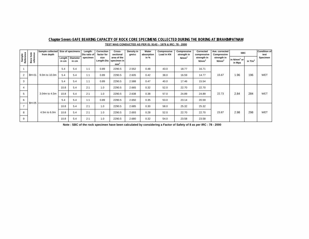
1 5.4 5.4 1:1 0.89 2290.5 2.552 0.48 43.0 18.77 16.71
2 5.4 5.4 1:1 0.89 2290.5 2.605 0.42 38.0 16.59 14.77
3 5.4 5.4 1:1 0.89 2290.5 2.588 0.47 40.0 17.46 15.54
4 10.8 5.4 2:1 1.0 2290.5 2.665 0.32 52.0 22.70 22.70
5 10.8 5.4 2:1 1.0 2290.5 2.638 0.38 57.0 24.89 24.89
6 5.4 5.4 1:1 0.89 2290.5 2.650 0.35 53.0 23.14 20.59
7 10.8 5.4 2:1 1.0 2290.5 2.685 0.30 58.0 25.32 25.32
8 10.8 5.4 2:1 1.0 2290.5 2.693 0.28 52.0 22.70 22.70
9 10.8 5.4 2:1 1.0 2290.5 2.680 0.32 54.0 23.58 23.58
BH-05
2.84 284 WET
4.5m to 6.0m 23.87 2.98 298 WET
Note : SBC of the rock specimen have been calculated by considering a Factor of Safety of 8 as per IRC : 78 - 2000
SBC
in N/mm2 or in Mpa in T/m2
Length in cm
Cross-sectional
area of the specimen in
mm2
1.96
3.04m to 4.5m 22.73
BH-01
Chapter Seven:-SAFE BEARING CAPACITY OF ROCK CORE SPECIMENS COLLECTED DURING THE BORING AT IBRAHIMPATNAMTEST WAS CONDUCTED AS PER IS: 9143 – 1979 & IRC: 78 - 2000
9.0m to 10.0m 15.67
Sam
ple
Ref
eren
ce
Bor
e ho
le
refe
renc
e Sample collected from depth
Corrected compressive strength in
N/mm2
Ave. corrected Compressive strength in
N/mm2
Correction factor for
size Length:Dia
WET196
Condition of test
Specimen
Length: Dia ratio of specimen
Size of specimens
Diameter in cm
Compressive Load in KN
Compressive strength in
N/mm2
Density in gm/cc
Water absorption
in %
GEOTECHNICAL INVESTIGATION REPORT: ARCHITECTURE & ENGINEERING CONSULTANCY SERVICES PVT. LTD.
Chapter Eight: Analysis of the Sub Surface Investigation The analysis of the sub-surface investigation test result of the soil samples collected during boring for the “Soil Investigation for Static test facility for propellants at BDL, Ibrahimpatnam.” BH : 1
1. It is seen that, from 0.0m to 3.0m depth, a rock strata is encountered and broken rock pieces were collected during boring, wherein three SPTs were conducted at 1.0m, 2.0m and 3.0m depth. The field N values from SPT are found to be more than 50.
2. From 3.0m to 9.0m depth, a non-plastic, non-expansive and very dense compacted poorly graded sand is presented, wherein five SPTs were conducted at each 1.5m depth interval. The field N values from SPT are found to be more than 50.
3. From 9.0m to 10.0m depth, (max depth explored) a rock strata is encountered, from which rock core samples were collected. The core recovery and RQD are found to be 33.0% and 0.0% respectively.
BH : 2
1. It is seen that, from 0.0m to 3.05m depth, a non-plastic non-expansive and medium to very dense compacted poorly graded sand strata is existing, wherein three SPTs were conducted at 1.0m, 2.0m and 3.0m depth. The field N values from SPT are found to be 27, 40 and more than 50 respectively.
2. From 3.05m to 6.0m depth, (max. depth explored) a rock strata is encountered and broken rock pieces were collected during boring, wherein two SPTs were conducted at 4.5m and 6.0m depth. The field N values from SPT are found to be more than 50.
BH : 3
1. It is seen that, from 0.0m to 1.05m depth, a non-plastic, non-expansive and very dense compacted poorly graded sand mixed with silt strata is existing, wherein one SPT was conducted at 1.0m depth. The field N value from SPT is found to be more than 50.
2. From 1.05m to 6.0m depth, (max. dept explored) a rock strata is encountered and broken rock pieces were collected during boring, wherein four SPTs were conducted at 2.0m, 3.0m, 4.5m and 6.0m depth. The field N values from SPT are found to be more than 50.
GEOTECHNICAL INVESTIGATION REPORT: ARCHITECTURE & ENGINEERING CONSULTANCY SERVICES PVT. LTD.
BH : 4 1. It is seen that, from 0.0m to 6.0m depth, (max. depth explored) a rock strata
is encountered and broken rock pieces were collected during boring, wherein five SPTs were conducted at 1.0m, 2.0m, 3.0m, 4.5m and 6.0m depth. The field N values from SPT are found to be more than 50.
BH : 5
1. It is seen that, from 0.0m to 2.4m depth, a non-plastic, non-expansive and dense to very dense graded compacted silty sand strata is presented, wherein two SPTs were conducted at 1.0m and 2.0m depth. The field N values from SPT are found to be 41 and more than 50 respectively.
2. From 2.4m to 3.04m depth, a non-plastic, non-expansive and dense compacted poorly graded sand mixed with silt strata is presented, wherein one SPT was conducted at 3.0m depth. The field N value from SPT is found to be more than 50.
3. From 3.04m to 6.0m depth (max. depth explored), a rock strata is encountered, from which rock core sample were collected. The core recoveries and RQDs are varying from 85.0% to 92.0% and 30.0% to 53.0%.
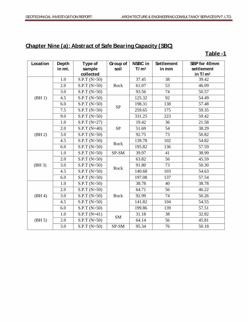
GEOTECHNICAL INVESTIGATION REPORT: ARCHITECTURE & ENGINEERING CONSULTANCY SERVICES PVT. LTD.
Chapter Nine (a): Abstract of Safe Bearing Capacity (SBC)
Table -1
Location Depth in mt.
Type of sample
collected
Group of soil
NSBC in T/m2
Settlement in mm
SBP for 40mm settlement
in T/m2
(BH 1)
1.0 S.P.T (N>50) Rock
37.45 38 39.42 2.0 S.P.T (N>50) 61.07 53 46.09 3.0 S.P.T (N>50) 93.56 74 50.57 4.5 S.P.T (N>50)
SP
125.32 92 54.49 6.0 S.P.T (N>50) 198.31 138 57.48 7.5 S.P.T (N>50) 259.65 175 59.35 9.0 S.P.T (N>50) 331.25 223 59.42
(BH 2)
1.0 S.P.T (N=27) SP
19.42 36 21.58 2.0 S.P.T (N=40) 51.69 54 38.29 3.0 S.P.T (N>50) 92.75 73 50.82 4.5 S.P.T (N>50)
Rock 139.78 102 54.82
6.0 S.P.T (N>50) 195.82 136 57.59
(BH 3)
1.0 S.P.T (N>50) SP-SM 39.97 41 38.99 2.0 S.P.T (N>50)
Rock
63.82 56 45.59 3.0 S.P.T (N>50) 91.80 73 50.30 4.5 S.P.T (N>50) 140.68 103 54.63 6.0 S.P.T (N>50) 197.08 137 57.54
(BH 4)
1.0 S.P.T (N>50)
Rock
38.78 40 38.78 2.0 S.P.T (N>50) 64.71 56 46.22 3.0 S.P.T (N>50) 92.99 74 50.26 4.5 S.P.T (N>50) 141.82 104 54.55 6.0 S.P.T (N>50) 199.86 139 57.51
(BH 5) 1.0 S.P.T (N=41)
SM 31.18 38 32.82
2.0 S.P.T (N>50) 64.14 56 45.81 3.0 S.P.T (N>50) SP-SM 95.34 76 50.18

GEOTECHNICAL INVESTIGATION REPORT: ARCHITECTURE & ENGINEERING CONSULTANCY SERVICES PVT. LTD.
(b) Abstract of Safe Bearing Capacity of rock
Table – 2
Location Rock specimens collected from
Condition of specimen test
SBC Type of rock in MPa in T/m2
(BH 1) 9.0m to 10.0m depth Set – 1 Wet 1.96 196 Soft Rock
(BH 5) 3.04m to 4.5m depth Set – 1 Wet 2.84 284 Hard Rock 4.5m to 6.0m depth Set – 1 Wet 2.98 298 Hard Rock
Remarks: As per IRC: 78 – 2000,
Type of rock Suggested Allowable Bearing Values for Ave. Condtn. a. Hard Rocks ---------------------- 2.0 MPa to 3.0 MPa b. Soft Rocks ------------------------ 1.0 MPa to 2.0 MPa c. Weathered Rocks, Conglomerates & Laterites ---- Not more than 1.0 MPa

GEOTECHNICAL INVESTIGATION REPORT: ARCHITECTURE & ENGINEERING CONSULTANCY SERVICES PVT. LTD.
Chapter Ten: Conclusion & Recommendations
1. Five boreholes have been advanced for the proposed project for the “Soil investigation for Static test facility for propellants at BDL Ibrahimpatnam.”
2. Standing water table was not found during boring.
3. In the present case, the superstructure load is not known. Hence a low to
moderate column load has been assumed.
4. The bearing capacity has been calculated as per IS: 6403, IS: 8009(pt-1), IS:
9143 and IRC-78-2000. The sample calculations are attached herewith.
5. It is suggested that an isolated square footing may be considered suitable for
the proposed structures at 2.0m depth below the OGL, considering the SBP
30.0T/m2 corresponding to settlement of 40mm.
6. However considering the SBP as mentioned at Chapter nine, the designer
may estimate the depth & Size of footing as per requirement.
7. For the safety of the structure a tie beam may be provided, to avoid the
differential settlement. If the column load varies considerably, in such case
also the tie beams become essential to avoid differential settlement.
8. Hyderabad city is included in the zone II of earthquake with low seismic
intensity of Z=0.10.Hence due precautions may be taken to design the
foundations of building as per IS:4326 and IS:1893.
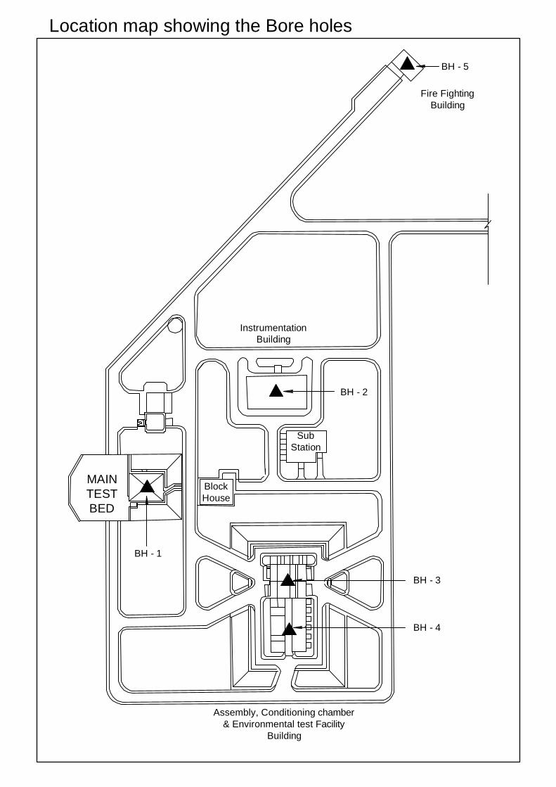
MAINTESTBED
BlockHouse
InstrumentationBuilding
SubStation
Fire FightingBuilding
Assembly, Conditioning chamber& Environmental test Facility
Building
BH - 5
BH - 2
BH - 3
BH - 4
BH - 1
Location map showing the Bore holes