Embed Size (px)
Citation preview
___________________
___________________
___________________
___________________
___________________
___________________
___________________
___________________
___________________
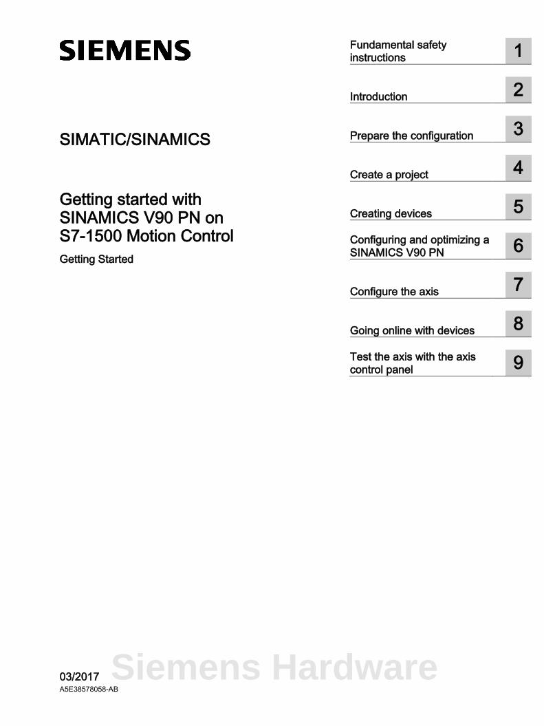
SIMATIC/SINAMICS
Getting started with SINAMICS V90 PN on S7-1500 Motion Control Getting Started
03/2017 A5E38578058-AB
Fundamental safety instructions
1
Introduction 2
Prepare the configuration 3
Create a project 4
Creating devices 5
Configuring and optimizing a SINAMICS V90 PN
6
Configure the axis 7
Going online with devices 8
Test the axis with the axis control panel
9
Siemens Hardware
Siemens AG Division Digital Factory Postfach 48 48 90026 NÜRNBERG GERMANY
A5E38578058-AB Ⓟ 05/2017 Subject to change
Copyright © Siemens AG 2016 - 2017. All rights reserved
Legal information Warning notice system
This manual contains notices you have to observe in order to ensure your personal safety, as well as to prevent damage to property. The notices referring to your personal safety are highlighted in the manual by a safety alert symbol, notices referring only to property damage have no safety alert symbol. These notices shown below are graded according to the degree of danger.
DANGER indicates that death or severe personal injury will result if proper precautions are not taken.
WARNING indicates that death or severe personal injury may result if proper precautions are not taken.
CAUTION indicates that minor personal injury can result if proper precautions are not taken.
NOTICE indicates that property damage can result if proper precautions are not taken.
If more than one degree of danger is present, the warning notice representing the highest degree of danger will be used. A notice warning of injury to persons with a safety alert symbol may also include a warning relating to property damage.
Qualified Personnel The product/system described in this documentation may be operated only by personnel qualified for the specific task in accordance with the relevant documentation, in particular its warning notices and safety instructions. Qualified personnel are those who, based on their training and experience, are capable of identifying risks and avoiding potential hazards when working with these products/systems.
Proper use of Siemens products Note the following:
WARNING Siemens products may only be used for the applications described in the catalog and in the relevant technical documentation. If products and components from other manufacturers are used, these must be recommended or approved by Siemens. Proper transport, storage, installation, assembly, commissioning, operation and maintenance are required to ensure that the products operate safely and without any problems. The permissible ambient conditions must be complied with. The information in the relevant documentation must be observed.
Trademarks All names identified by ® are registered trademarks of Siemens AG. The remaining trademarks in this publication may be trademarks whose use by third parties for their own purposes could violate the rights of the owner.
Disclaimer of Liability We have reviewed the contents of this publication to ensure consistency with the hardware and software described. Since variance cannot be precluded entirely, we cannot guarantee full consistency. However, the information in this publication is reviewed regularly and any necessary corrections are included in subsequent editions.
Getting started with SINAMICS V90 PN on S7-1500 Motion Control Getting Started, 03/2017, A5E38578058-AB 3
Table of contents
1 Fundamental safety instructions .............................................................................................................. 5
1.1 General safety instructions ....................................................................................................... 5
1.2 Industrial security ...................................................................................................................... 6
1.3 Danger to life due to software manipulation when using removable storage media ................ 7
2 Introduction ............................................................................................................................................. 8
2.1 Drive system - Overview ........................................................................................................... 8
2.2 "Getting started" objectives ....................................................................................................... 9
2.3 Sample project .......................................................................................................................... 9
3 Prepare the configuration ...................................................................................................................... 11
3.1 Requirements .......................................................................................................................... 11
3.2 Restoring factory settings ....................................................................................................... 12
3.3 Result of the preparations ....................................................................................................... 12
4 Create a project .................................................................................................................................... 13
4.1 Overview ................................................................................................................................. 13
4.2 Create new project .................................................................................................................. 13
4.3 Result in the sample project ................................................................................................... 14
5 Creating devices ................................................................................................................................... 15
5.1 Adding devices from the hardware catalog ............................................................................ 15
5.2 Connecting devices ................................................................................................................. 16
5.3 Operate devices in isochronous mode ................................................................................... 18
5.4 Result in the sample project ................................................................................................... 18
6 Configuring and optimizing a SINAMICS V90 PN .................................................................................. 19
6.1 Overview ................................................................................................................................. 19
6.2 Connect online ........................................................................................................................ 19
6.3 Checking drive configuration .................................................................................................. 20
6.4 Performing an optimization ..................................................................................................... 21
6.5 Loading the optimized data from the device ........................................................................... 23
6.6 Saving data in the drive .......................................................................................................... 23
6.7 Result in the sample project ................................................................................................... 23
Siemens Hardware
Table of contents
Getting started with SINAMICS V90 PN on S7-1500 Motion Control 4 Getting Started, 03/2017, A5E38578058-AB
7 Configure the axis ................................................................................................................................. 24
7.1 Overview ................................................................................................................................ 24
7.2 Technology object axis .......................................................................................................... 24
7.3 Creating an axis ..................................................................................................................... 25
7.4 Configuring the hardware interface ........................................................................................ 25
7.5 Result in the sample project ................................................................................................... 29
8 Going online with devices...................................................................................................................... 30
9 Test the axis with the axis control panel ................................................................................................ 31
9.1 Overview ................................................................................................................................ 31
9.2 Working with the axis control panel ....................................................................................... 32
9.3 Result in the sample project ................................................................................................... 33
Index .................................................................................................................................................... 34
Getting started with SINAMICS V90 PN on S7-1500 Motion Control Getting Started, 03/2017, A5E38578058-AB 5
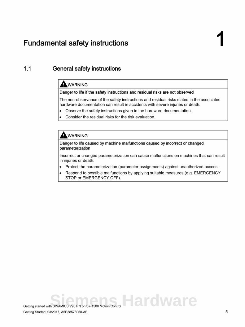
Fundamental safety instructions 1 1.1 General safety instructions
WARNING
Danger to life if the safety instructions and residual risks are not observed
The non-observance of the safety instructions and residual risks stated in the associated hardware documentation can result in accidents with severe injuries or death. • Observe the safety instructions given in the hardware documentation. • Consider the residual risks for the risk evaluation.
WARNING
Danger to life caused by machine malfunctions caused by incorrect or changed parameterization
Incorrect or changed parameterization can cause malfunctions on machines that can result in injuries or death. • Protect the parameterization (parameter assignments) against unauthorized access. • Respond to possible malfunctions by applying suitable measures (e.g. EMERGENCY
STOP or EMERGENCY OFF).
Siemens Hardware
Fundamental safety instructions 1.2 Industrial security
Getting started with SINAMICS V90 PN on S7-1500 Motion Control 6 Getting Started, 03/2017, A5E38578058-AB
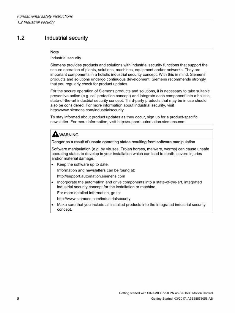
1.2 Industrial security
Note Industrial security
Siemens provides products and solutions with industrial security functions that support the secure operation of plants, solutions, machines, equipment and/or networks. They are important components in a holistic industrial security concept. With this in mind, Siemens’ products and solutions undergo continuous development. Siemens recommends strongly that you regularly check for product updates.
For the secure operation of Siemens products and solutions, it is necessary to take suitable preventive action (e.g. cell protection concept) and integrate each component into a holistic, state-of-the-art industrial security concept. Third-party products that may be in use should also be considered. For more information about industrial security, visit http://www.siemens.com/industrialsecurity.
To stay informed about product updates as they occur, sign up for a product-specific newsletter. For more information, visit http://support.automation.siemens.com
WARNING
Danger as a result of unsafe operating states resulting from software manipulation
Software manipulation (e.g. by viruses, Trojan horses, malware, worms) can cause unsafe operating states to develop in your installation which can lead to death, severe injuries and/or material damage. • Keep the software up to date.
Information and newsletters can be found at: http://support.automation.siemens.com
• Incorporate the automation and drive components into a state-of-the-art, integrated industrial security concept for the installation or machine. For more detailed information, go to: http://www.siemens.com/industrialsecurity
• Make sure that you include all installed products into the integrated industrial security concept.
Fundamental safety instructions 1.3 Danger to life due to software manipulation when using removable storage media
Getting started with SINAMICS V90 PN on S7-1500 Motion Control Getting Started, 03/2017, A5E38578058-AB 7
1.3 Danger to life due to software manipulation when using removable storage media
WARNING
Danger to life due to software manipulation when using removable storage media
The storage of files on removable storage media involves a high risk of infection, e.g. via viruses or malware. Incorrect parameter assignment can cause machines to malfunction, which can lead to injuries or death. • Protect the files on removable storage media against harmful software through
appropriate protective measures, e.g. virus scanners.
Siemens Hardware

Getting started with SINAMICS V90 PN on S7-1500 Motion Control 8 Getting Started, 03/2017, A5E38578058-AB
Introduction 2 2.1 Drive system - Overview
This document describes the engineering of a SINAMICS V90 PN integrated in the TIA Portal. This engineering can be installed later with the HSP 0185 hardware support package. SINAMICS V90 PN with this engineering can be operated only on a technology object (TO) for the Axis type of a SIMATIC S7-1500 and must be interconnected with this via PROFINET.
Configuration and parameter assignment The TIA Portal is available for the configuration and parameter assignment of the SINAMICS V90 PN drive system.
With the TIA Portal and SINAMICS V90 PN, you can perform the following tasks, for example:
● Create a project.
● Add the drive system to the project and interconnect it with a higher-level controller.
● Configure the drives (selection of the variants).
● Create a technology object.
● Go online on the drive and test the parameter assignment via the axis control panel.
● Perform diagnostics when an error occurs.
User interface The graphic user interface provides support during the configuration and parameter assignment:
● Select the drive in the hardware catalog.
● In the "Network view", interconnect the drive with a higher-level controller and assign parameters for the communication via PROFINET.
● In online mode, test the drive with the drive control panel and load the parameter assignment to the drive.
Introduction 2.2 "Getting started" objectives
Getting started with SINAMICS V90 PN on S7-1500 Motion Control Getting Started, 03/2017, A5E38578058-AB 9
Further information at a glance Getting Started
● SINAMICS V90 PROFINET, SIMOTICS S-1FL6 Getting Started (https://support.industry.siemens.com/cs/de/en/view/109737879)
Device documentation
● SINAMICS V90 PN / SIMOTICS S-1FL6 operating instructions (https://support.industry.siemens.com/cs/de/en/view/109737880)
2.2 "Getting started" objectives "Getting Started" provides an introduction to configuring SINAMICS V90 PN in conjunction with a technology object Axis of a SIMATIC S7-1500 in the TIA Portal Engineering System. You create a simple sample project by performing the typical optimization and configuration steps for the device, drive and axis configuring. You become acquainted with the most important tools that the TIA Portal provides for the configuring, commissioning and diagnostics of the SINAMICS V90 PN.
2.3 Sample project Create a simple sample project based on "Getting Started".
Configuration steps
Preparing the configuration
● If necessary, restore the factory settings (Page 12) for the devices.
● You configure the interface for the network communications (Page 25) of the PG/PC with SINAMICS V90 PN and SIMATIC S7-1500.
Creating a project, configuring the devices and the network communications with the PG/PC
● Create a project (Page 13).
● Create SINAMICS V90 PN and SIMATIC S7-1500 (Page 15) and define the communications between the PG/PC and devices (Page 16).
Configuring SIMATIC S7-1500 and the technology object Positioning axis
● Configure a SIMATIC S7-1500 controller (Page 19).
● Define an axis (Page 25).
● Interconnect the axis with the drive (Page 25).
Siemens Hardware
Introduction 2.3 Sample project
Getting started with SINAMICS V90 PN on S7-1500 Motion Control 10 Getting Started, 03/2017, A5E38578058-AB
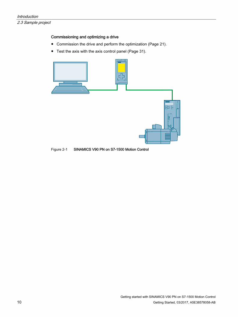
Commissioning and optimizing a drive
● Commission the drive and perform the optimization (Page 21).
● Test the axis with the axis control panel (Page 31).
Figure 2-1 SINAMICS V90 PN on S7-1500 Motion Control
Getting started with SINAMICS V90 PN on S7-1500 Motion Control Getting Started, 03/2017, A5E38578058-AB 11
Prepare the configuration 3 3.1 Requirements
Device requirements You require the following components to create the sample project:
● SINAMICS V90 PN with a 1FL6 motor
● SIMATIC S7-1500
● PG/PC with free Ethernet interface
● TIA Portal Engineering System as of V14 with the associated HSP 0185 (SINAMICS V90 PN)
Preparing the system Your system is prepared for configuring with the TIA Portal:
● The hardware is preassembled and wired.
● The latest firmware of the V90 PN is available.
● PG/PC is connected directly with the PROFINET interface of the controller (S7-1500) via the Ethernet line.
● TIA Portal (at least V14) is installed on the PG/PC.
● HSP 0185 (SINAMICS V90 PN) is installed on the PG/PC.
● The TIA Portal is open. The portal view is open on the PG/PC screen.
Siemens Hardware
Prepare the configuration 3.2 Restoring factory settings
Getting started with SINAMICS V90 PN on S7-1500 Motion Control 12 Getting Started, 03/2017, A5E38578058-AB
3.2 Restoring factory settings The reset to the factory settings is not normally necessary. If the current settings of the drive are not known or the settings cause errors that can no longer be reproduced, you can restore the factory settings of the drive. You so restore the default parameters.
If required you can restore the factory settings of the drive with "Online & diagnostics" > "Save/reset".
The following parameters are not affected by the factory settings:
● p8920[0...239] PN: Name of station
● p8921[0...3] PN: IP address of station
● p8922[0...3] PN: Default gateway of station
● p8923[0...3] PN: Subnet mask of station
If necessary, also reset these interface parameters to the factory settings via "Online & Diagnostics" > "Functions" > "Reset interface parameters".
3.3 Result of the preparations ● The devices are prepared and the requirements have been checked.
● If necessary, the devices are reset to the factory settings.
● The requirements for online communication are satisfied.
Getting started with SINAMICS V90 PN on S7-1500 Motion Control Getting Started, 03/2017, A5E38578058-AB 13
Create a project 4 4.1 Overview
In this "Getting started" section, you create the "Sample_1" sample project in the TIA Portal. All of the subsequent configuring steps refer to this sample project.
4.2 Create new project After opening the TIA Portal, you find yourself in the portal view. The portal view offers a task-oriented view of the tools, and provides the basic functions for the individual task areas.
Siemens Hardware
Create a project 4.3 Result in the sample project
Getting started with SINAMICS V90 PN on S7-1500 Motion Control 14 Getting Started, 03/2017, A5E38578058-AB
To create a new project You begin a new configuring by creating a new project in the TIA Portal.
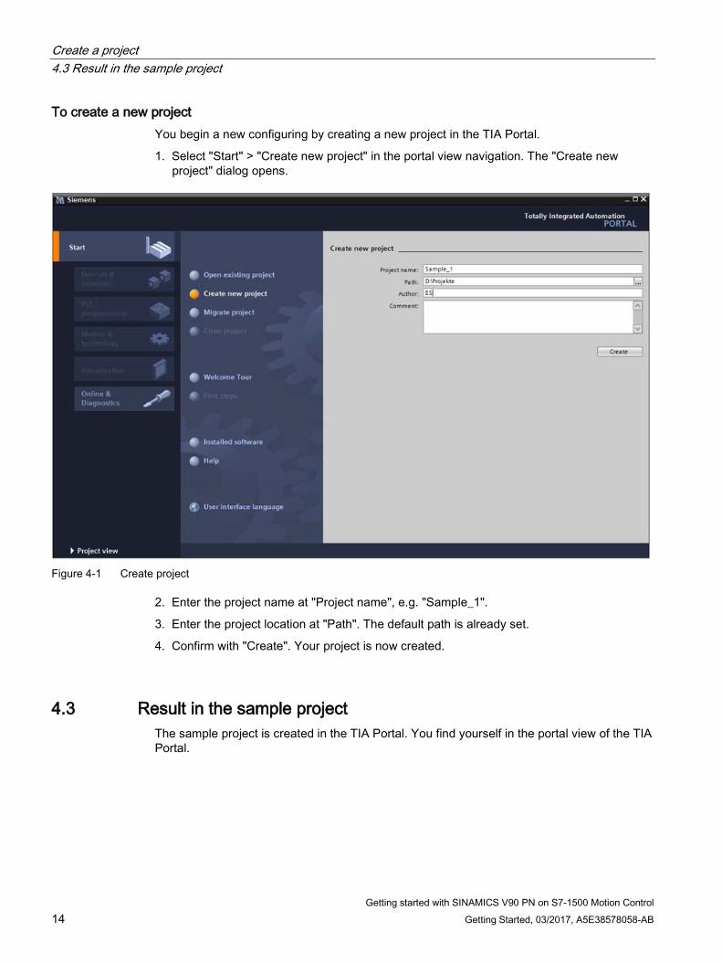
1. Select "Start" > "Create new project" in the portal view navigation. The "Create new project" dialog opens.
Figure 4-1 Create project
2. Enter the project name at "Project name", e.g. "Sample_1".
3. Enter the project location at "Path". The default path is already set.
4. Confirm with "Create". Your project is now created.
4.3 Result in the sample project The sample project is created in the TIA Portal. You find yourself in the portal view of the TIA Portal.
Getting started with SINAMICS V90 PN on S7-1500 Motion Control Getting Started, 03/2017, A5E38578058-AB 15
Creating devices 5 5.1 Adding devices from the hardware catalog
To add devices directly from the hardware catalog:
1. Open the project view of the TIA Portal by clicking the "Open project view" button and double-click "Devices and networks" in the Project Navigator.
The network view opens. The hardware catalog appears on the right-hand side.
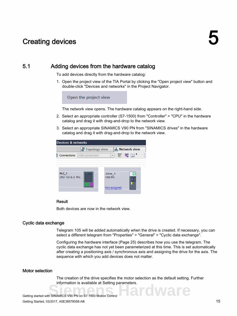
2. Select an appropriate controller (S7-1500) from "Controller" > "CPU" in the hardware catalog and drag it with drag-and-drop to the network view.
3. Select an appropriate SINAMICS V90 PN from "SINAMICS drives" in the hardware catalog and drag it with drag-and-drop to the network view.
Result
Both devices are now in the network view.
Cyclic data exchange Telegram 105 will be added automatically when the drive is created. If necessary, you can select a different telegram from "Properties" > "General" > "Cyclic data exchange".
Configuring the hardware interface (Page 25) describes how you use the telegram. The cyclic data exchange has not yet been parameterized at this time. This is set automatically after creating a positioning axis / synchronous axis and assigning the drive for the axis. The sequence with which you add devices does not matter.
Motor selection The creation of the drive specifies the motor selection as the default setting. Further information is available at Setting parameters.
Siemens Hardware
Creating devices 5.2 Connecting devices
Getting started with SINAMICS V90 PN on S7-1500 Motion Control 16 Getting Started, 03/2017, A5E38578058-AB
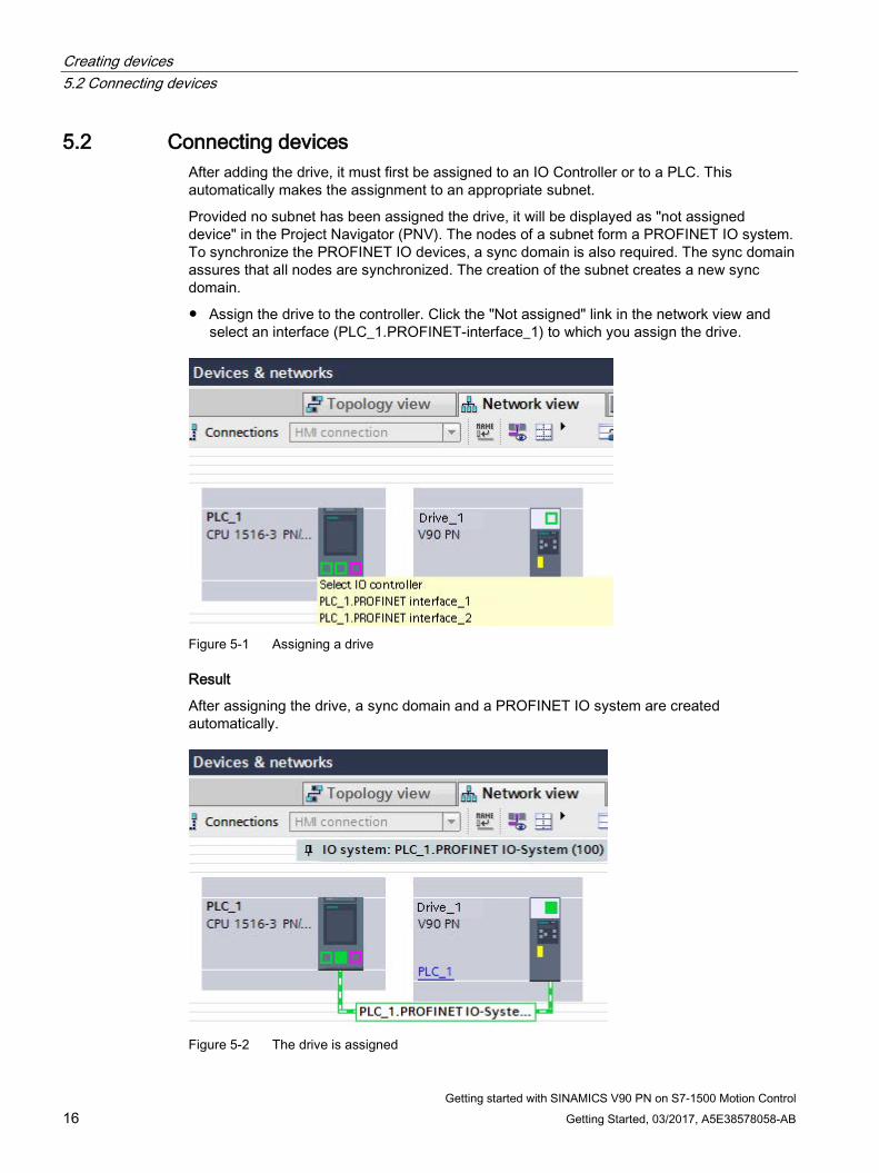
5.2 Connecting devices After adding the drive, it must first be assigned to an IO Controller or to a PLC. This automatically makes the assignment to an appropriate subnet.
Provided no subnet has been assigned the drive, it will be displayed as "not assigned device" in the Project Navigator (PNV). The nodes of a subnet form a PROFINET IO system. To synchronize the PROFINET IO devices, a sync domain is also required. The sync domain assures that all nodes are synchronized. The creation of the subnet creates a new sync domain.
● Assign the drive to the controller. Click the "Not assigned" link in the network view and select an interface (PLC_1.PROFINET-interface_1) to which you assign the drive.
Figure 5-1 Assigning a drive
Result
After assigning the drive, a sync domain and a PROFINET IO system are created automatically.
Figure 5-2 The drive is assigned
Creating devices 5.3 Operate devices in isochronous mode
Getting started with SINAMICS V90 PN on S7-1500 Motion Control Getting Started, 03/2017, A5E38578058-AB 17
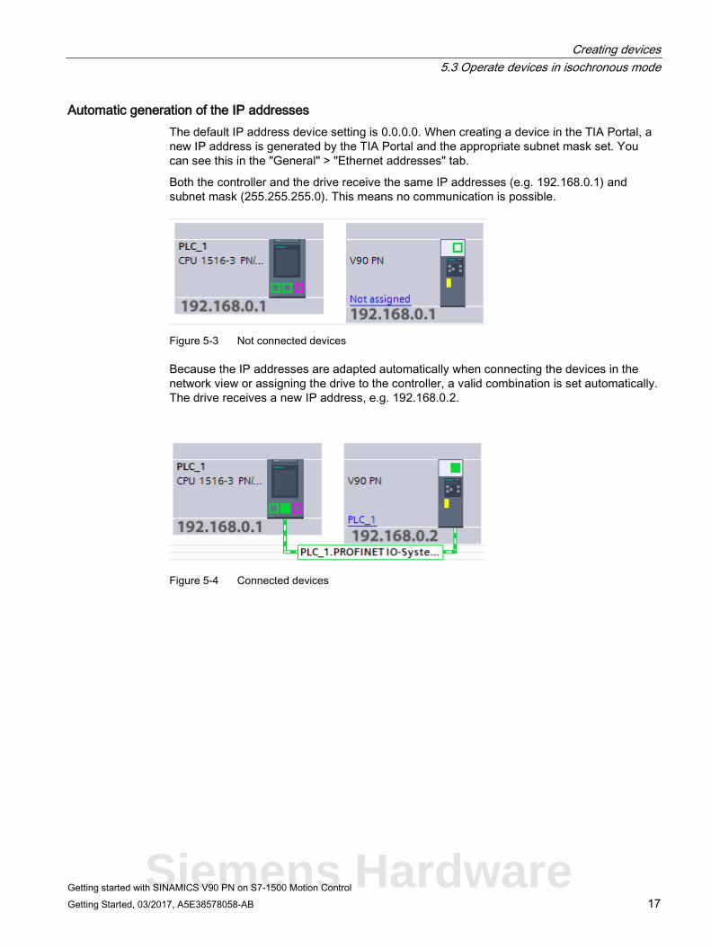
Automatic generation of the IP addresses The default IP address device setting is 0.0.0.0. When creating a device in the TIA Portal, a new IP address is generated by the TIA Portal and the appropriate subnet mask set. You can see this in the "General" > "Ethernet addresses" tab.
Both the controller and the drive receive the same IP addresses (e.g. 192.168.0.1) and subnet mask (255.255.255.0). This means no communication is possible.
Figure 5-3 Not connected devices
Because the IP addresses are adapted automatically when connecting the devices in the network view or assigning the drive to the controller, a valid combination is set automatically. The drive receives a new IP address, e.g. 192.168.0.2.
Figure 5-4 Connected devices
Siemens Hardware
Creating devices 5.3 Operate devices in isochronous mode
Getting started with SINAMICS V90 PN on S7-1500 Motion Control 18 Getting Started, 03/2017, A5E38578058-AB
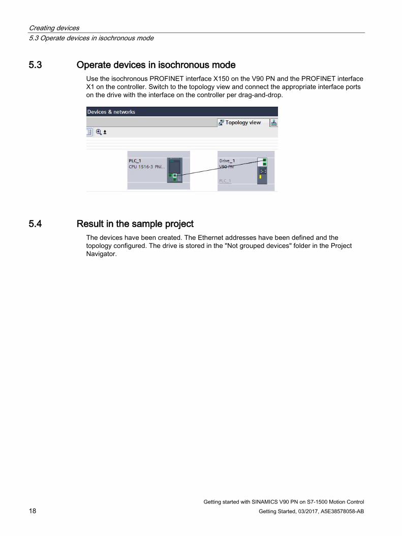
5.3 Operate devices in isochronous mode Use the isochronous PROFINET interface X150 on the V90 PN and the PROFINET interface X1 on the controller. Switch to the topology view and connect the appropriate interface ports on the drive with the interface on the controller per drag-and-drop.
5.4 Result in the sample project The devices have been created. The Ethernet addresses have been defined and the topology configured. The drive is stored in the "Not grouped devices" folder in the Project Navigator.
Getting started with SINAMICS V90 PN on S7-1500 Motion Control Getting Started, 03/2017, A5E38578058-AB 19
Configuring and optimizing a SINAMICS V90 PN 6 6.1 Overview
The following step of the example concerns both the optimization of the drive in conjunction with an S7-1500 controller and also with a drive not assigned to any controller.
6.2 Connect online
The drive is connected with the controller If the drive is connected with the controller via isochronous interfaces, it goes into cyclic operation automatically in accordance with the wiring and configuration.
Establish an online connection:
1. Select the drive in the Project Navigator.
2. To do this, click the button.
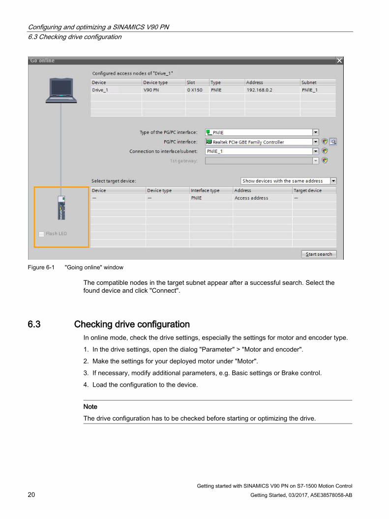
3. Enter the PG/PC interface type and the PG/PC interface in the "Connect online" window.
4. Select "PN/IE_1" from "Connection with interface/subnet".
5. Click "Start search".
Siemens Hardware
Configuring and optimizing a SINAMICS V90 PN 6.3 Checking drive configuration
Getting started with SINAMICS V90 PN on S7-1500 Motion Control 20 Getting Started, 03/2017, A5E38578058-AB
Figure 6-1 "Going online" window
The compatible nodes in the target subnet appear after a successful search. Select the found device and click "Connect".
6.3 Checking drive configuration In online mode, check the drive settings, especially the settings for motor and encoder type.
1. In the drive settings, open the dialog "Parameter" > "Motor and encoder".
2. Make the settings for your deployed motor under "Motor".
3. If necessary, modify additional parameters, e.g. Basic settings or Brake control.
4. Load the configuration to the device.
Note
The drive configuration has to be checked before starting or optimizing the drive.
Configuring and optimizing a SINAMICS V90 PN 6.4 Performing an optimization
Getting started with SINAMICS V90 PN on S7-1500 Motion Control Getting Started, 03/2017, A5E38578058-AB 21
6.4 Performing an optimization Optimize the drive by performing a turning measurement with coupled load. The appropriate procedure is described in the following section.
The "Optimization" window is opened from "Drive" > "Commissioning" > "Control panel / optimization" in the Project Navigator; select the second tab at the top right.
1. First fetch master control.
2. Configure the settings and, if necessary, the extended settings. Set the maximum motion angle for each direction manually (phase 2 of the measurement). We recommend that you enter 360 degrees manually.
Note
When setting the maximum motion angle, consider how the axis should move with coupled load.
3. Click the "Start optimization" button. The turning measurement is performed.
4. Return the master control after the successful optimization.
5. Load the data to the drive to save the settings permanently.
WARNING
Danger for persons and machinery caused by a turning motor.
The motor must be able to turn freely by +/-720 degrees for incremental encoders.
Siemens Hardware
Configuring and optimizing a SINAMICS V90 PN 6.5 Loading the optimized data from the device
Getting started with SINAMICS V90 PN on S7-1500 Motion Control 22 Getting Started, 03/2017, A5E38578058-AB
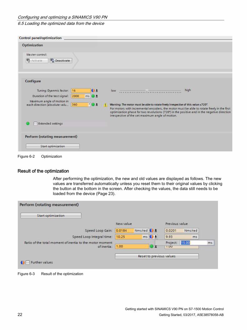
Figure 6-2 Optimization
Result of the optimization After performing the optimization, the new and old values are displayed as follows. The new values are transferred automatically unless you reset them to their original values by clicking the button at the bottom in the screen. After checking the values, the data still needs to be loaded from the device (Page 23).
Figure 6-3 Result of the optimization
Configuring and optimizing a SINAMICS V90 PN 6.5 Loading the optimized data from the device
Getting started with SINAMICS V90 PN on S7-1500 Motion Control Getting Started, 03/2017, A5E38578058-AB 23
6.5 Loading the optimized data from the device After the optimization, the optimized values are located in the volatile memory on the device.
You can change the online value directly and then copy it to the drive. The actual value can also be changed for directly editable parameters. The change is transferred directly to the drive.
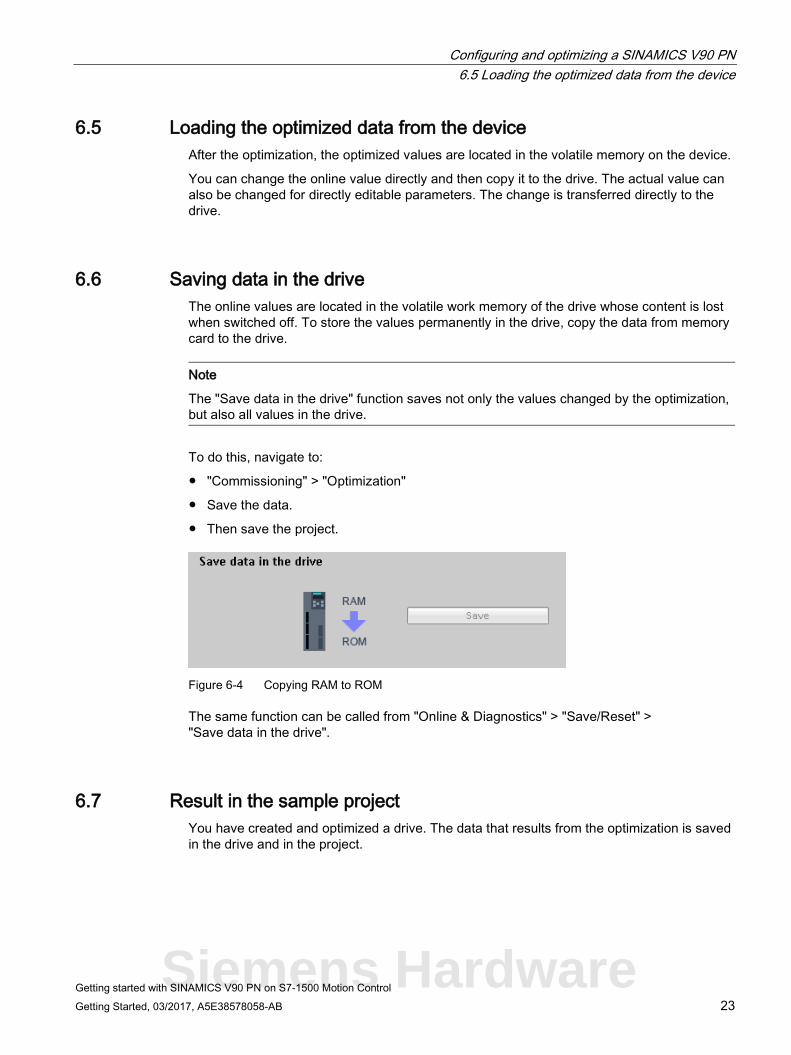
6.6 Saving data in the drive The online values are located in the volatile work memory of the drive whose content is lost when switched off. To store the values permanently in the drive, copy the data from memory card to the drive.
Note
The "Save data in the drive" function saves not only the values changed by the optimization, but also all values in the drive.
To do this, navigate to:
● "Commissioning" > "Optimization"
● Save the data.
● Then save the project.
Figure 6-4 Copying RAM to ROM
The same function can be called from "Online & Diagnostics" > "Save/Reset" > "Save data in the drive".
6.7 Result in the sample project You have created and optimized a drive. The data that results from the optimization is saved in the drive and in the project.
Siemens Hardware
Getting started with SINAMICS V90 PN on S7-1500 Motion Control 24 Getting Started, 03/2017, A5E38578058-AB
Configure the axis 7 7.1 Overview
This section describes how you create and configure a positioning axis in the project, and interconnect it with the SINAMICS V90 PN drive.
Requirement You have created the drive as described in the Creating devices (Page 15) section.
7.2 Technology object axis Technology objects (TOs) represent the associated real objects (e.g. a positioning axis) in the controller.
The technology object Positioning axis / Synchronous axis provides a technological view of the drive and the encoder (actuator and sensor), provides technological functions for them and contains the concrete hardware interconnection.
The technology object Positioning axis / Synchronous axis contains extensive functionality, e.g. communication with the drive, actual value processing, position control, and positioning functionality. It executes control and motion commands and indicates states and actual values.
Technological limitations and values for the mechanical system for the axis and encoder are set on the axis. You can then work exclusively with technological variables.
Configure the axis 7.3 Creating an axis
Getting started with SINAMICS V90 PN on S7-1500 Motion Control Getting Started, 03/2017, A5E38578058-AB 25
7.3 Creating an axis Create the "PositioningAxis_1" axis for the sample project. Assign a drive to the axis.
How to create an axis in the project 1. Open the Controller folder in the Project Navigator and select "Technology objects".
2. Double-click "Add new object". The "Add new object" dialog opens.
3. Select from "Motion Control" a "TO_PositioningAxis" positioning axis.
4. Enter a name for the axis. Use the designation "PositioningAxis_1" for the axis of the sample project.
5. Leave the other preset values to their default values.
6. Click "OK".
The "Basic parameters" window opens in the function view.
See also Configuring and optimizing a SINAMICS V90 PN (Page 19)
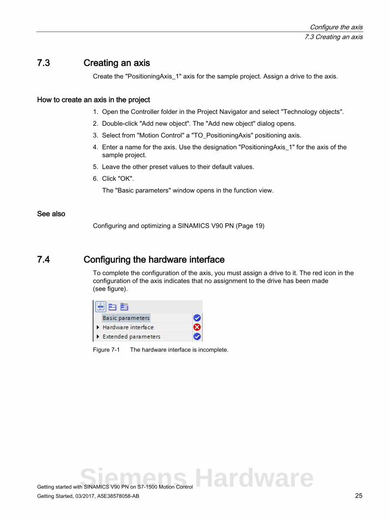
7.4 Configuring the hardware interface To complete the configuration of the axis, you must assign a drive to it. The red icon in the configuration of the axis indicates that no assignment to the drive has been made (see figure).
Figure 7-1 The hardware interface is incomplete.
Siemens Hardware
Configure the axis 7.4 Configuring the hardware interface
Getting started with SINAMICS V90 PN on S7-1500 Motion Control 26 Getting Started, 03/2017, A5E38578058-AB
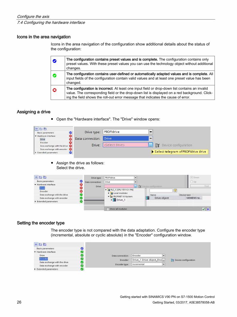
Icons in the area navigation Icons in the area navigation of the configuration show additional details about the status of the configuration:
The configuration contains preset values and is complete. The configuration contains only preset values. With these preset values you can use the technology object without additional changes.
The configuration contains user-defined or automatically adapted values and is complete. All input fields of the configuration contain valid values and at least one preset value has been changed.
The configuration is incorrect. At least one input field or drop-down list contains an invalid value. The corresponding field or the drop-down list is displayed on a red background. Click-ing the field shows the roll-out error message that indicates the cause of error.
Assigning a drive ● Open the "Hardware interface". The "Drive" window opens:
● Assign the drive as follows:
Select the drive.
Setting the encoder type The encoder type is not compared with the data adaptation. Configure the encoder type (incremental, absolute or cyclic absolute) in the "Encoder" configuration window.
Configure the axis 7.4 Configuring the hardware interface
Getting started with SINAMICS V90 PN on S7-1500 Motion Control Getting Started, 03/2017, A5E38578058-AB 27
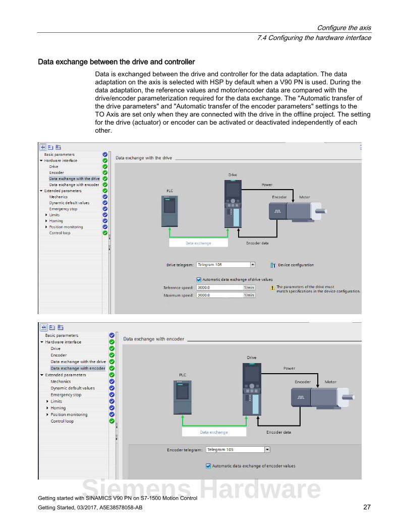
Data exchange between the drive and controller Data is exchanged between the drive and controller for the data adaptation. The data adaptation on the axis is selected with HSP by default when a V90 PN is used. During the data adaptation, the reference values and motor/encoder data are compared with the drive/encoder parameterization required for the data exchange. The "Automatic transfer of the drive parameters" and "Automatic transfer of the encoder parameters" settings to the TO Axis are set only when they are connected with the drive in the offline project. The setting for the drive (actuator) or encoder can be activated or deactivated independently of each other.
Siemens Hardware
Configure the axis 7.4 Configuring the hardware interface
Getting started with SINAMICS V90 PN on S7-1500 Motion Control 28 Getting Started, 03/2017, A5E38578058-AB
Which data is adapted?
All actuator and encoder data that must be set identical in the technology object Axis to the associated data in the drive is adapted:
● Actuator data on the TO Axis: "Reference speed", "Reference torque", "Maximum speed"
● Encoder data on the TO Axis: "Increments per revolution", "Number of revolutions", "Fine resolution Xact1", "Fine resolution Xact2"
The following is always performed for activated adaptation:
● For each TO Power up (after controller power up or loading the TO to the controller).
● For each restoration after drive failure, namely always after a station restoration of the drive that belongs to the associated technology object.
● For each restart of a technology object.
After a successful adaptation
After a successful adaptation, the actual values of the adapted data are overwritten in the associated TO-DB. The adapted data, however, is not stored automatically on the memory card of the drive and also not transferred as initial values in an offline project.
If the adapted data should not be stored permanently, the following two possibilities are available:
● Save the adapted data in the offline project and the subsequent download: If the adapted data should be saved in the offline project, TIA Portal functions can be used: Call the "Snapshot of the actual values" function to store the actual values of the associated TO-DB as snapshot in the offline project, then call the "Copy the momentary values to the initial values" function to transfer them to the initial values of the associated TO-DB in the offline project and finally load the TO-DB stored in the offline project to the CPU.
● Save the adapted data on the memory card: Call the SFC "WRIT_DBL" in the user program to save the actual values of the adapted data on the memory card.
Configure the axis 7.5 Result in the sample project
Getting started with SINAMICS V90 PN on S7-1500 Motion Control Getting Started, 03/2017, A5E38578058-AB 29
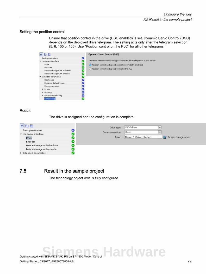
Setting the position control Ensure that position control in the drive (DSC enabled) is set. Dynamic Servo Control (DSC) depends on the deployed drive telegram. The setting acts only after the telegram selection (5, 6, 105 or 106). Use "Position control on the PLC" for all other telegrams.
Result The drive is assigned and the configuration is complete.
7.5 Result in the sample project The technology object Axis is fully configured.
Siemens Hardware
Getting started with SINAMICS V90 PN on S7-1500 Motion Control 30 Getting Started, 03/2017, A5E38578058-AB
Going online with devices 8
Load the sample project with the axis configuration to the controller so that the function of the axis can be tested with the axis control panel in the next step.
Load the project 1. Save the project
2. Compile the project
3. Select the controller in the Project Navigation.
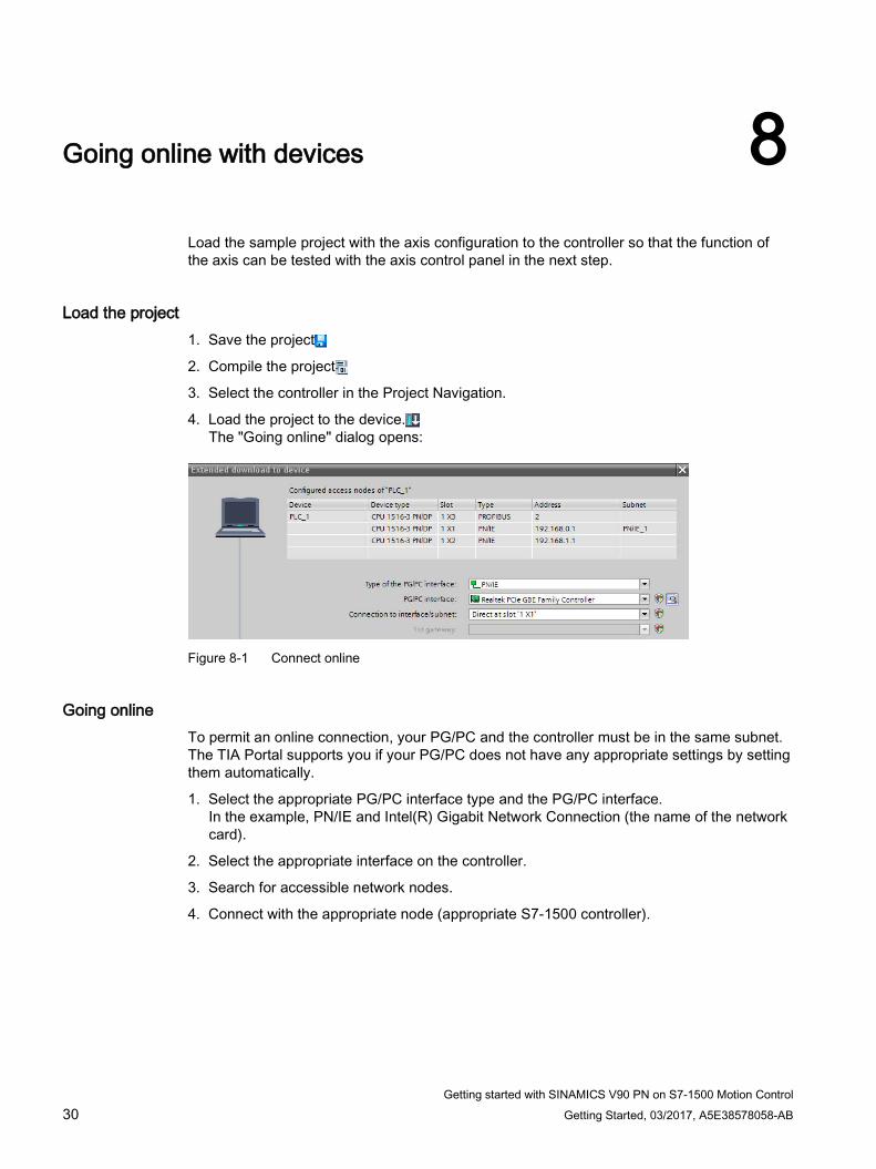
4. Load the project to the device. The "Going online" dialog opens:
Figure 8-1 Connect online
Going online To permit an online connection, your PG/PC and the controller must be in the same subnet. The TIA Portal supports you if your PG/PC does not have any appropriate settings by setting them automatically.
1. Select the appropriate PG/PC interface type and the PG/PC interface. In the example, PN/IE and Intel(R) Gigabit Network Connection (the name of the network card).
2. Select the appropriate interface on the controller.
3. Search for accessible network nodes.
4. Connect with the appropriate node (appropriate S7-1500 controller).
Getting started with SINAMICS V90 PN on S7-1500 Motion Control Getting Started, 03/2017, A5E38578058-AB 31
Test the axis with the axis control panel 9 9.1 Overview
In this "Getting Started" section, you test the configured axis. TIA Portal provides the axis control panel for this purpose.
Requirements ● The devices have been created and configured, see Section Creating devices (Page 15).
● You have configured the motor in the drive, see Configuring and optimizing a SINAMICS V90 PN (Page 19).
● The drive configuration is loaded to the device, see Configuring and optimizing a SINAMICS V90 PN (Page 19).
● Motor, encoder and motor holding brake are connected to the drive.
● The drive is supplied with power, 24 V and 230/400 V.
● The ports of the PROFINET interfaces are wired in accordance with the port interconnection.
● The STO must be connected correctly.
● An axis in the sample project has been created and configured, see Section Configure the axis (Page 24).
● The project with the axis configuring is loaded to the target system.
● The axis is not switched on via a motion command (MC_Power).
Note Further information concerning the requirements
Further information for the V90 PN is available in the SINAMICS V90, SIMOTICS S-1FL6 operating instructions.
Further information concerning technology objects and motion topics is available in the online help for the TIA Portal at "Deploying technology functions" > "Motion control".
Siemens Hardware
Test the axis with the axis control panel 9.2 Working with the axis control panel
Getting started with SINAMICS V90 PN on S7-1500 Motion Control 32 Getting Started, 03/2017, A5E38578058-AB
9.2 Working with the axis control panel You traverse individual axes with the axis control panel.
A user program is not necessary for the operation of the axis control panel. With the axis control panel, you take over master control for a technology object and control the axis motions.
WARNING
Uncontrolled axis motions
During operation with the axis control panel, the axis can execute uncontrolled motions (e.g. due to erroneous configuration of the drive, or of the technology object). Furthermore, any synchronized following axis is moved as well when moving a leading axis with the axis control panel.
Therefore, perform the following protective measures before operation with the axis control panel: • Ensure that the EMERGENCY OFF switch is within the reach of the operator. • Enable the hardware limit switches. • Enable the software limit switches. • Ensure that following error monitoring is enabled. • Make sure that no following axis is coupled to the axis to be moved.
Traversing the drive with the axis control panel
1. Open the axis control panel of the technology object Positioning axis from "Technology object > Commissioning" in the Project Navigator. The "Axis control panel" window opens.
2. Fetch master control.
3. Set the drive enable.
4. Select "Jogging" operating mode.
Test the axis with the axis control panel 9.3 Result in the sample project
Getting started with SINAMICS V90 PN on S7-1500 Motion Control Getting Started, 03/2017, A5E38578058-AB 33
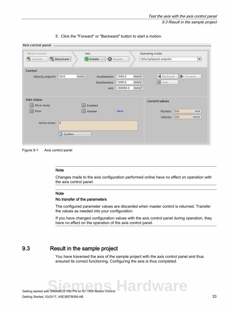
5. Click the "Forward" or "Backward" button to start a motion.
Figure 9-1 Axis control panel
Note
Changes made to the axis configuration performed online have no effect on operation with the axis control panel.
Note No transfer of the parameters
The configured parameter values are discarded when master control is returned. Transfer the values as needed into your configuration.
If you have changed configuration values with the axis control panel during operation, they have no effect on the operation of the axis control panel.
9.3 Result in the sample project You have traversed the axis of the sample project with the axis control panel and thus ensured its correct functioning. Configuring the axis is thus completed.
Siemens Hardware
Getting started with SINAMICS V90 PN on S7-1500 Motion Control 34 Getting Started, 03/2017, A5E38578058-AB
Index
S SINAMICS V90 PN
Drive system - Overview, 8, 8 SINAMICS V90 PN on S7-1500 Motion Control
Performing an optimization, 21
V V90 PN with SIMATIC S7-1500 "Getting Started"
Adding devices from the hardware catalog, 15 Configuring the hardware interface, 25 Connecting devices, 16 Connecting online, 19 Create new project, 14 Creating an axis, 25 Defining the topology, 18 Going online with devices, 30 Loading the optimized data from the device, 23 Restoring factory settings, 12 Sample project, 9 Saving data in the drive, 23 Technology object Axis, 24 Working with the axis control panel, 32