Embed Size (px)
Citation preview

HMV GM 07-100 SA-M
handbook
1 General information Delivery – Handling – Installation – Start up Operation Maintenance and care Thread dies HMV type L – Execution & maintenance Stoppage – Trouble shooting – Actions Spindle rpm—cutting speed—diameter Accessories and equipment Enclosures
2
3
4
5
6
7
8
Semi-automatic thread cutting machine with hydraulic powered clamp and die head
Read the handbook carefully before using the machine and make sure it is available for future use. In order to ensure safe and correct operation— Read the Safety guide lines from the General information section before using the machi-ne.
9
MMMM Specially equipped with manual drive mode and handwheel for manual sled feed.

2
CONTENT 1. General information 4
1.1 Manufacturers declaration of conformity……………………………………. 1.2 Safety guidelines for thread cutting machine GM07-100 SA…………………. 1.3 Different parts of the machine………………………………………………….
1.3.1 Overview…………………………………………………………………….. 1.3.2 Die head GH5 with die holder for right hand threads…………………...
2. Delivery – Handling – Installation – Start up 13
2.1 Delivery…………………………………………………………………………. 2.2 Handling………………………………………………………………………... 2.3 Installation………………………………………………………………………. 2.4 Start up…...……………………………………………………………………...
3. Operation 18
3.1 Control units…………………………………………………………………… 3.2 Operation panel………………………………………………………………... 3.2.1 Menu I: Automatic drive mode……………………………………... 3.2.2 Menu II: Manual drive mode………………………………………... 3.2.3 Menu III: Jog drive mode………….………………………………… 3.2.4 Menu VI: Alarm and other settings…………………………………. 3.3 Drive modes……………………………………………………………………... 3.3.1 Automatic drive mode………………………………………………... 3.3.2 Manual drive mode…………………………………………………... 3.3.3 Jog drive mode………………………………………………………… 3.4 Inspecting / Adjusting the die head – Opening / closing………………….... 3.5 Assembly / Adjusting thread dies…………………………………………….
4. Maintenance and care 34
4.1 Daily inspection – machine care………………………………………………… 4.2 Monthly inspection or after 100 hours of operation…….…………………… 4.3 Annual inspection………………………………………………………………… 4.4 Preemptive measures in the event of long stand stills………………………
5. Thread dies HMV type L – Execution and maintenance 36
6. Stoppage – Trouble shooting – Actions 38
6 7 10 10 12
13 14 15 17
18 20 20 22 23 24 26 26 28 29 30 32
34 35 35 35

3
7. Accessories and equipment 41
7.1 Thread dies…………………………………………………………………… 7.2 Grinding fixture for HMV thread dies…………………………………………… 7.3 Die holders for extreme thread pitches.…………………………………… 7.4 Die holder for left hand threads…………………………………………………
8. Spindle rpm—cutting speed—diameter 44
9. Enclosures 45 9.1 Enclosure 1 – Handling………………………………………………………… 9.2 Enclosure 2 – Wiring diagram—Connection……………………………….. 9.3 Enclosure 3 – Wiring diagram—PLC and control system…………………. 9.4 Enclosure 4 – Wiring diagram cabinet A4 hydraulic unit………………….. 9.5 Enclosure 5 – Circuit diagram HYDAC Hybox flex mini…………………...
41 42 42 43
45 46 47 48 49

4
General information
This handbook contains instructions and guideIines for HMV machines GM 07-100 SA. This handbook is intended to secure the function of the machine for its whole lifespan and minimize the risks of personal injury or damage caused by work done with or on the machine. We hope this machine will meet your expectation and that the information gi-ven in this handbook is satisfactory. JBL Mekan AB guarantees that GM 07-100 SA meets the requirements ac-cording to EG:s machine directive.
The machine is CE marked according to applicable rules and regulations. GM 07-100 SA is a complete machine. The CE marking is only valid if the machine is used in it’s original execution or is completed with products appro-ved by JBL Mekan AB.
The warranty is only valid if the machine is used and maintained according to the manufacturers instructions and used with thread cutting dies and spa-re parts delivered by HMV machines. Any departure from these rules have to be approved by JBL Mekan AB. Any modification or upgrade have to be approved by JBL Mekan AB. HMV machines GM 07-100 SA is manufactured and marketed by JBL Me-kan AB, Rosenfors, Sweden, a family owned business that also owns HMV machines.

5
Thread cutting machine GM 07-100 SA is intended for outer thread cutting of round bars that are 16—100 mm in diameter. The diameter of the round bars can be no more than 2 mm larger than the finished thread. In the standard clamping dies, the length of the bar to be threaded must be at least 90 mm longer than the thread length to ensure that the bar is safely attatched. Round bars of different materials can be threaded. Every different materials properties must be considered when loading and adjusting the machine. Personell servicing, working in or on the machine must be well informed of the machines functions and operations and must have taken part of the infor-mation in this handbook as well as the rules and regulations of heavy duty mechanical– or construction environments and be aware of the inherant risks and hazards. Always keep a copy of this handbook available for the personell working with or on the machine. In the last section of this handbook you will find space for your notes. Our hope is that you make a note of when and how the machine was installed as well as any other measures you have made, such as service, problems and solutions and any other information that can be helpful in maintaining the best function. Our machines are under continuous developement and you are always wel-come to contact us with any information and feedback that hopefully will lead to a solution to your problem or an improvement of upcoming machines.
General information
6
1.1 Manufacturers declaration of conformity
according to 2006/42/EG – Enclosure 2A
Manufacturer: JBL Mekan AB Address: Lillesjövägen 19, SE570 83 Rosenfors Sweden Contact person: Stefan Saugsted Company name: JBL Mekan AB Address: Lillesjövägen 19, SE570 83 Rosenfors Sweden Declares under sole responsiblity that thread cutting machine
HMV GM 07 – 100 SA with Serialnumber:………………………. is in conformity with the essential requirements in Machinery Directive 2006/42/EG. Furthermore, the machine is guaranteed to meet all the essential requirements in the: Low Voltage Directive (LVD) 2006/95/EG Electromagnetic Compatability Directive (EMC) 2004/108/EG And conforms completely with below stated standards and technincal specifications: EN ISO 12100 Safety Of Machinery EN ISO 14121 Risk assessment EN ISO 13849 Safety-related parts of control sy-stems
AFS 2008:3
Date Signature
………………………………………… Stefan Saugsted,
General information

7
1.2 Safety guidelines for thread cutting machine GM07-100SA
• The machine must be transported and handled according to the in-
structions provided by JBL Mekan AB (see enclosure 1). • The machine must be installed and connected according to the instruc-
tions provided by JBL Mekan AB (see enclosure 2). • The machine must only be used for intended purposes accounted for in
this handbook. • Personell servicing or working on or with the machine must be infor-
med of the content in this handbook and understand the function and operation of the machine.
• The operator must not perform other tasks during operation that can
divert attention from the potential risks. • When the die head cover is lifted, e.g when changing or setting the
thread cutting dies, the machines main switch must be in the ”0” posi-tion.
• Be aware of the risk of crushing when: - Adjusting the thread dies - Clamping the bar - The clamping dies opens/closes - The sled is moving Eliminating the risk of crushing has been estimated to be very limited and unsafe. When working on or with the machine, personal injury can easily be avoided by executing operations with a tight grip and keeping limbs outside of hazardous areas. • The clamp of the machine is only to be maneuvered when all precau-
tion has been made thus eliminating the risk of personal injury. • The die head must be set to open at least 10 mm before the sled rea-
ches the die head cover.
General information

8
• Only move the sled when all precaution has been made thus elimina-ting the risk of personal injury. Be aware that a bar being threaded dri-ves the sled towards the die head with great force. In the event of an emergency, the movement can be stopped by pressing the right button on the control panel.
• In the event of an unforeseen emergency situation, all movement and
operation can be halted by pressing the emergency stop which is pla-ced in the middle of the control panel.
• The machine can be equipped with a laser module (pointer) which ser-
ves as a guide when placing the bar in the clamp. It is a low effect laser and is only hazardous when looking straight into it. There is no risk of personal injury when looking at the laser beam from the side. *
• Make sure to clear the machine from tools or material unessential to
operation before operation. • All material must be placed in such a way as to not limit the freedom of
movement or constitute any other risk for the person servicing, working in or on the machine.
• The rules and regulations of the Swedish Working Enviroment Authority
or an equivalent organisation or company issued rules and regulations apply when handling goods or material to, in and from the machine.
* Not available in standard execution.
General information

9
General information

10
General information
1.3 Different parts of the machine—Overview
. .
A) Bars on the clamp and halter B) Start = Green Stop = Red C) For electrical equipment and drive system D) Accesses the hydraulic unit E) Opens die head (under sled) F) Adjustment of thread length G) Not available in standard execution.
1
2
3
4
6
7
10
11
9
1 Die head cover
2 Coolant nozzle
3 Symmetric clamp
4 Handwheel - sled feed
5 Control panel
6 Chip container - Coolant tank
7 Safety opening of thread dies A)
8 Operation panel
9 Drive belt cover
10 Start – Stop B)
Front side

11
General information
1
4 2
3 5
1. S11 button, closes clamp. 2. S14 button, closes die head. 3. S4 button, emergency stop. 4. S13 button, opens die head. 5. S10 button, opens clamp.
5. Control panel
F1
F6
F0
F5
F2
F7
F3
F8
F4
F9
Enter
ALARM
RS-232
RS-435
Esc
Shift
Up
PgUp
Pg Dn
Down
Left Right
8. Operation panel
16
12 13
14
1815
15 Breaker E)
16 Door F)
17 Laser module (pointer) G)
18 Photocell sensor
11 Door, cabinet for electric equipment
12 Main switch
13 Cooling fan C)
14 Scale and stop for sled D)
Left-hand short side
Right-hand short side
17

12
1.3.2 Die head GH5 with die holder for right hand threads
General information
1 Die head body
2 Halter
3 Die holder - standard for approx. pitch angle 1 – 3,5 degrees
4 Thread die template – Thread dies mounting
5 Thread dies
6 Adjustment screw - thread dies position in die holder
7 Adjustment screw - thread diameter
8 Scale – Rough adjustment of thread diameter (M– and UNC threads)
9 Adjustment screw - spring tightening, readjustment open - close
7 1
3
8
9
2 4
5
6

13
2.1 Delivery
The machine is delivered completely assembled and packaged in such a way as to protect it well from all types of transport damage. All rough surfa-ces has been sprayed with corrosion inhibitor.
The machine crate is designed to be handled by a fork lift with a lift capacity of at least 1,2 tons (12kN). The forks must be fully widened when lifting the crate.
An ocular inspection of the crate and the machine must be done immediatly upon delivery. Any possible damage must be reported to the transporter so that a report can be made according to the transporters routines.
The wooden crate should be dissembled in sections in the following order: Lid, long sides and gables.
Check the quantity of the recieved goods against the delivery note as soon as possible. Any remark as to the quantity of the delivery is only valid if made within 8 days of delivery to JBL Mekan AB.
Remove the volatile corrosion inhibitor paper and the anti corrosion grease while the machine is still placed on the crate base. Remove the anti corro-sion grease with grease solvent and wipe dry with a cloth and use compres-sed air if necessary.
Thread cutting machine GM 07-100 SA must be kept in a non-condensing environment with a relative humidity lower than 90% and a tempature of –20 - +40^C.
Delivery – Handling – Installation - Start up

14
Delivery – Handling – Installation - Start up
2.2 Handling
Thread cutting machine GM 07-100 SA must be handled according to below instructions.
When handling the machine it is recommended to use a forklift with forks long enough to reach all the way through the machine frame via the fork passages. The forks should be at least 1 meter in length.
When lifting the machine with a traverse crane, insert 2 steel rods (Ø25, length min. 1,3m) through both fork passages in the bottom of the frame. At-tach approx. 2m long strops at both ends of both rods. Attach all strops to the lift yoke according to the instructions. The strops must be attached in such a away as to prevent it from sliding on the rods or the lift yoke.
When lifting and transporting the machine with a forklift, the machine must be secured in such a way as to prevent it from sliding on the forks.
The machine must not under any circumstances be lifted in any other way than by using the fork passages in the machine frame. See enclosure 1.

15
2.3 Installation
Set up
The placement of the machine must allow access of both the short sides and the front side of the machine.
The distance between the right-hand short side of the machine to the nea-rest wall or other obstruction must be at least 60cm.
The distance between the front side of the machine to another workspace must be at least 1m and to any other obstruction, the distance must be at least 1,2m.
The operating area must be easy to access and exit even when material waiting to be worked is placed in the area of the machine.
Material must not be placed in such a way as to limit the movement requi-red to operate the machine.
The distance between the back of the machine to the nearest wall or ob-struction must be at least 80cm in order to be able to perform necessary in-spections and service of the hydraulic equipment.
Detaching the back cover will ease work when performing certain repara-tions.
The machine must be placed on a firm and leveled surface where it is not exposed to vibrations or interferences from other workspaces.
The level of the machine must not differ more than 5mm end to end.
Delivery – Handling – Installation - Start up

16
Delivery – Handling – Installation - Start up
It is important that the right-hand short side machine is standing on both corners and at least 200mm in the middle of the free end.
Normal use does not require the machine to be fixed to the ground.
On a sloping floor or if the machine tends to move on the surface it is re-commended to place the machine on a 5 - 10mm thick rubber mat (approx. 70shore).
If the machine for some reason is fixed to the ground, it is important that the attachment does not cause strain on the frame.
Make room for the enclosed tools and setting templates where they are easy to store and access.
Connection
Connect the machine to the electricity supply network 3x400VAC. The ma-chine must be secured through a 20-25A fuse. Connect phase lead L1, L2 and L3 to the vacant connections of the main switch. Neutral wire N, (0) and protective earth Pe (yellow/green) to the reserved connections on the mon-tage plate in the A1 machine cabinet. See enclosure 2.

17
2.4 Start up
Before starting the machine for the first time, make sure to check the hyd-raulic oil level. Fill with VG32 OR VG46 hydraulic oil if necessary. The ma-chine is delivered with VG32 hydraulic oil.
The oil level gauge is situated on the tank of the hydraulic unit and is ac-cessed by opening the door on the gable. The level must be between the two lines on the scale of the oil level gauge.
Before running the coolant pump of the machine make sure to fill the coo-lant container (situated under the chip container) up to the folded edge. The coolant level is appropriate when the coolant reaches the plate edges but not above the ledge holding the coolant pump.
In order to obtain the best thread quality when threading steel materials, cutting oil should always be used.
All environmentally approved coolants can be used. Advice your coolant supplier to find the most appropriate coolant for the material you are threa-ding. If you intend to thread different types of materials, make sure to check with your supplier which coolants can be mixed together.
Note
If you do not want to use coolant when threading, disconnect the coolant pump (see Enclosure 2 – F3, in off-position).
Delivery – Handling – Installation - Start up

18
3.1 Control units
Both the main switch and safety switch (HB) is located on the leading edge of the gable on the driving side of the machine. the main switch must al-ways set to the ”0” (off) position whenever the machine is being serviced, maintained or adjusted. Please note that the main switch has current run-ning through it even when set to the ”0” position. The frequency control units maintains high currents even long after the main swicth has been set to the ”0” position. The Start button (S1) and the Stop button (S2) is located on the door of the machine cabinet (A1). The Start button activates the cooling fans, power supply unit, frequency control units, PLC-control and operating panel. The stop button deactivates all these functions. The emergency stop, the red mushroom button located on the control panel, breaks the line voltage. Depressing this button halts all functions instantly. Reset the machine by turning the button upwards to the default position. The emergency stop must only be used if there is a risk of personal injury. The PLC-program is reset every time the machine is started by pressing the Start button (S1). Quantity threaded is set to 1 and thread direction is set to right. Left hand threading must be selected before thread sequence. The PLC-program saves thread diameter (e.g. M20x2,5), thread length (e.g. 100), cutting speed (e.g. 12,0) and the distance from photocell to the die. These values remain even after the machine is restarted by pressing the Start button (S1). The value for start position is saved from previous opera-tion and can be set when starting the automatic operation.
Operation

19
Operation
1
4 2
3 5
F1
F6
F0
F5
F2
F7
F3
F8
F4
F9 Enter
ALARM
RS-232
RS-435
Esc
Shift
Up
PgUp
Pg Dn
Down
Left Right
The control panel The control panel, located on the front of the machine has 4 buttons, two of which opens/closes the die head (S13, S14). The S10 and S11 buttons opens/closes the clamp. The S4 button is the emergency stop. The S11 button also signals to the PLC that a new bar is loaded which initiates the threading.
Arrow keys PgUp, PgDn, L (left), R (right) are used to navigate the menus and edit values in the registries. The Enter key confirms and registers the selections. Menus of the operation panel
1. S11 button, closes clamp. 2. S14 button, closes die head. 3. S4 button, emergency stop. 4. S13 button, opens die head. 5. S10 button, opens clamp.
The operation panel The operation panel, located on the spindle housing, allows the operator to select thread, thread length and cutting speed.
5 dual acting function keys below the display are used to select functions F0—F4. Holding down the Shift key when pressing the function keys enables functions F5—F9. A square symbol is visible in the lower left corner of the display when the Shift key is depressed. These keys can also be used to edit values in the registries.
Menu I Automatic drive mode Menu II Manual drive mode Menu III Jog drive mode Menu IV Alarm and other settings

20
3.2.1 Operation panel—Menu I: Automatic drive mode
When the machine is started (S1 button) and the PLC and the display is ready, the main menu is displayed. The main menu offers an overview of the automatic drive information, settings and options. 1. Navigation indicator Informs the user that it is possible to navigate to the next menu by pressing the Down arrow key (PgDn). 2. Thread direction indicator Reads ”L” when the die head rotation is set for left-hand threads. 3. Set thread Set the thread that matches the installed thread dies by browsing the thread registry. Included in the registry are 19 threads by which 18 are standard metric coarse threads and 1 custom thread. Press the Right arrow key (R) to browse forward and the Left arrow key (L) to browse backward in the re-gistry. 4. Set thread diameter To set thread diameter (16,0 – 100,0 ), press F1 and set the value with F0—F9. In this registry, these keys only have a numeric function. The value can also be changed by using the arrow keys: Up (PgUp), Down (PgDn), Left (L) and Right (R). Press the Enter key to confirm the selection. The new va-lue will now be displayed.
Operation
5
7
9
3
4
6
8
10 11
2
1

21
Operation
5. Set thread pitch To set thread pitch (1,000—20,000mm), press F2 and edit the value using the same method. Dia mm x P mm can be used for all threads that are not already occupied in the registry, e.g. a UNC-thread UNC ½ - 13 => Dia mm = 25,4 / 2 => Dia mm= 12,7 => P mm = 25,4 / 13 => P mm = 1,954 6. Set thread length To set thread length, press F3 and set the value by the same method as pre-viously described. 7. Set start position To set start position, press F4 and set the value by the same method as pre-viously described. The value will set the distance the sled travels to reach the die head cover and is added to the thread length. This length makes up the area where the front end of the workpiece will be located and must be long enough that the front end of the bar is not triggering the photocell sen-sor. The green and a yellow LED light on the sensor are switched off when the photocell is triggered. 8. Set Cutting speed To set cutting speed, press F6 and set the value by the same method as pre-viously described. The value will set the spindle rpm for the selected thread. This is valid for manual fed thread cutting as well. Only the thread diameter needs to be taken into account. 9. Threading counter The number of pieces that has been threaded is displayed below ”RstF9”. Pressing F9 will reset the registry. 10. Automatic drive mode On/Off To start the automatic drive mode, press F0. 11. Automatic drive mode indicator Is higlighted when the automatic drive mode is active.

22
3.2.2 Operation panel—Menu II: Manual drive mode
The manual menu offers an overview of the manual drive settings and op-tions. 1. Navigation indicators The indicators ”PgD” and ”PgU” informs the user that it is possible to navi-gate to the next menu by pressing the Down arrow key(PgDn) or the previo-us menu by pressing the Up arrow key (PgUp). 2. Set thread diameter To set thread diameter (16,0 – 100,0 ), press F1 and set the value with F0—F9. In this registry, these keys only have a numeric function. The value can also be changed by using the arrow keys: Up (PgUp), Down (PgDn), Left (L) and Right (R). Press the Enter key to confirm the selection. The new va-lue will now be displayed. 3. Set Cutting speed To set cutting speed, press F2 and set the value by the same method as previously described. The value will set the spindle rpm for the selected thread. Only the thread diameter needs to be taken into account. 4. Manual drive mode On/Off To start the Manual drive mode, press F0. 5. Manual drive mode indicator The F0 indicator is higlighted when the Manual drive mode is active. 6. Coolant pump On/Off Press F5 to start the coolant pump. 7. Coolant pump indicator The F0 indicator is higlighted when the Manual drive mode is active.
Operation
4
6
2
3 1
1
7
5

23
3.2.3 Operation panel—Menu III: Jog drive mode
The Jog drive menu offers an overview of the functions of the Jog drive mode. 1. Navigation indicators ”PgD” and ”PgU” informs the user that it is possible to navigate to the next menu by pressing the Down arrow key (PgDn) or the previous menu by pressing the Up arrow key (PgUp). 2. Jog drive mode On/Off To start Jog drive mode press F0. 3. Jog drive mode indicator The F0 indicator signals when the hydraulic unit powers up and stays high-lighted as long as the Jog drive mode is active. 4. Open/Close clamp Open/close clamp by pressing F3/F8. 5. Open/Close die head Open/close die head by pressing F2/F7. 6. Operate sled Use function keys F1/F4 to operate the sled. The sled will move as long as the key is depressed. 7. Run die head Use function key F6 to run the die head. The die head will run as long as the key is depressed.
Operation
1
1
6
5
4
7
2 3

24
Operation
3.2.4 Operation panel—Menu VI: Alarm and other settings
The Jog menu offers an overview of the functions of the Jog mode. 1. Navigation indicator The indicator ”PgU” informs the user that it is possible to navigate to the pre-vious menu by pressing the Up arrow key (PgUp). 2. Set length, photocell to thread dies 3. Set sled brake distance Press F2 to set the distance the sled travels when going from high speed to low speed when returning to starting position. 4. Set sled accelleration distance Press F3 to set the distance the sled travels when going from low speed to high speed. 5. Set die head rotation Press F4 to set die head rotation. 6. Die head rotation indicator The F4 indicator is higlighted when right-hand threading is selected. 7. Reset alarm, spindle overload Press F5 to reset the alarm.
1
8
10
2
3
4
5
6 9
7

25
8. Spindle overload alarm indicator The F5 indicator is higlighted when the alarm is active. 9. Reset alarm, feed motor overload Press F6 to reset the alarm. 10. Feed motor overload alarm indicator The F6 indicator is higlighted when the alarm is active.
Operation

26
Operation
3.3.1 Automatic drive mode
This is the standard drive mode and yields the best threading result. • First, the thread machine is started by pressing the S1 (green) button
on the machine cabinet door. • Select thread (see section 3.2). • Set start position (see section 3.2). • Start the drive mode (see section 3.2). The Automatic drive mode begins by the sled traveling towards the die head until it finds the front limit position and then traveling back to the start position. The front limit position also functions as a safety limit. It works to make sure that the sled does not come to close to the die head. A signal is transmitted to the die head commanding it to rotate while the sled is retur-ning to the start position. This is done in order to establish the threading direction. The sled returns to start position, the clamp opens and the ma-chine is ready to be loaded. Place the bar in the center of the clamp and press and hold the S11 mush-room button on the left of the control panel until the clamping dies grip. Once the clamping dies grip, the pressure builds up in the hydraulic cylin-der and the pressure transmitter G6 fixes the bar. The G6 transmitter then initiates the feed of the sled and the bar is fed towards the die head for threading. The automatic operation can be aborted by pressing the S10 mushroom button on the control panel if done so before the front end of the bar rea-ches the photocell sensor. Note The cutting speed is limited by the max. spindle rpm, approx. 360rpm (see section 8.1)

27
Operation
Once the front end of the bar reaches the photocell sensor, the spindle starts up and the feed of the sled is syncronized with the spindle rpm to match the thread pitch. The die head is closed and the coolant pump starts up. The PLC checks for selected thread length. The die head cover must not be lifted once the front end of the bar has passed the photcell sensors. Once the the selected thread length has been reached, the die head opens, the coolant pump stops pumping and the sled returns to starting position. When the sled has reached the starting position, the clamping dies open and the thread cutting machine is ready to load once again.
CAUTION
(1) When fixing the bar in the clamp, hold it in such a way as to avoid a crushing injury (2) The die head cover must not under any circumstan-ces be opened while the Automatic drive mode is active. If the die head cover is open, accidental contact with the buttons of the control panel might result in grave perso-nal injury. (3) Be aware of crushing hazard when maneuvering the clamp and when the thread cutting dies are guiding the workpiece towards the die head.

28
3.3.2 Manual drive mode
This mode is used when you want to operate the machine manually. The manual drive mode requires the machine to be modified: • The ball nut is removed from the sled. The sled is positioned as close to
the bearing of the loading side of the machine as possible. • The manual feed handwheel is pulled out until the gear joins the cog
rack. • The sensor recognizes the position of the handwheel axle and ensures
that the automatic sequence can not be activated when the axle is in a position where it is not joining the cog rack.
The thread machine is started by pressing the S1 (green) button on the ma-chine cabinet. • From Menu II, press function key F0. • The F0 indicator signals when the hydraulic unit powers up. • The control panel is now operational. • Mushroom buttons S10—S11 opens/closes the clamp. Buttons S12—S13 opens/closes the die head. • Activate cooling by pressing function key F5 • From Menu II, press the function key F0 to stop the operation. • This driving mode will also stop automatically when selecting F0 from
Menu I. Fix the bar in the clamp. Feed the sled with the fixed bar at a slow rate to-wards the die head. Press the S13 button on the control panel once the thread dies has reached the desired thread length to open the die head. Feed the bar backwards by means of the handwheel. The safety openning of the thread dies opens the die head automatically if the sled reaches its front position. The clamp is opened by pressing mushroom button S10
Operation

29
Operation
3.3.3 Jog mode
This mode is used for maintenance and troubleshooting when repairing the machine. The buttons on the control panel (S10—S14) are deactivated in Jog mode as a safety precaution. Jog mode is deactivated by pressing function key F0 from Menu III. Starting the Automatic drive mode from the main menu will deactivate Jog mode as well.

30
3.4 Inspecting / Adjusting the die head – Opening / closing
The die head is equipped with a prestressed spring that works to switch the adjustment ring and the die holders from opened to closed position when the halter has reached approx. half way between the positions during ad-justment.
The prestress of the spring, the sensor and the bar (Safety opening of thre-ad dies) should all be carefully adjusted upon delivery.
The setting mechanism can be hard worked the first time the die head is operated after the machine have been unutilized for a long period of time. The spring should be adjusted in order to inspect the function. When clo-sing the die head by pressing the S14 button, the die head cover must be closed.
Inspection:
• Press the S14 button on the control panel to close the die head
• Turn off the thread cutting machine and turn the main switch to the ”0” position.
• Open the die head cover and feed the sled towards the die head until the bar of the clamp and the bar of the halter meet. Carefully keep feeding the sled until the die head opens and the spring takes over the movement.
• Close the die head cover. The feed distance between the sled and the die head must be at least 15mm.
• Check to see if the sensor (for opening the die head) has been uneffec-ted and if the coil has released from the rails under the sled. If the coil has not released, carefully feed the sled towards the die head until the coil loses contact with the rail. The sled must not be in contact with the die head cover when the sensor breaks - adjusted the die head.
• Adjust the position of the sensor if necessary.
Operation
31
Adjust the adjustment screw. if the prestress of the spring needs to be ad-justed. Increase the prestress by turning the screw clockwise. Adjust no more than ¼ of a revolution at a time between every test operation.
The adjustment screw must not be turned excessivly because if the spring is completely compressed, the spring does not have any room for move-ment which will result in the thread dies not staying in closed position (which causes tapered threads) during operation or the die head not func-tioning at all.
If the spring loses its strength or if it has been tightened to the bottom, it must be replaced. Remove the adjustment screw and install a new spring (item no. 444801-5). The spring can be ordered from your machine supplier or directly from JBL Mekan AB. Replacing the spring with a spring of diffe-rent properties will result in the die head not functioning as intended.
Operation
CAUTION
Be aware of the risk of crushing when adjusting

32
3.5 Assembly / Adjusting thread dies
HMV Machines are marked with thread designation (e.g. M20 x 2,5) and are numbered 1 through 4. The die holders are also numbered 1 through 4. The numbers indicates in what order the dies are to be mounted and in which die holder. Never mix thread dies from diffierent sets. Before the thread cutting dies are placed in the die holders, make sure that they are clean and that the seats of the die holders are free of chips and dirt. The die head can easily be turned by hand to the the desired position when mounting and adjusting the thread dies. Mount the thread dies in the corres-ponding die holders according to the numbering. Start with no.1, end with no. 4. The cutting edges of the thread dies are displaced by ¼ of the pitch angle of the thread. If the thread dies are mounted in the wrong order, the thread result will not be adequate.
Use the included adjustment template to adjust the position of the die in the die holder. A scale for different diameters is marked on the template and a guide line is located on every die holder. Place the template on the die hol-der with its locating tooth resting against the cutting teeth of the die. Adjust the thread die by turning the adjustment screw on the die holder until the gui-de line on the template representing the diameter being threaded is inline with the guide line on the die holder. Fix the thread die by means of the screws that are located on the thread die template. Mount and adjust all the thread dies into the correct position using this method. Adjusting the position of thread dies according to the above instructions normally results in high qu-ality threads if performed thoroughly.
If the obtained thread quality is not satisfactory, inspect the position of the thread dies by means of the included adjustment angle. Hold one side of the angle against the die with the outer edge of the angle in line with the edge of the cutting tooth. The other side of the angle must touch the edge of the cut-ting tooth of the opposed die.
Operation

33
Operation
Adjust the incorrectly positioned die. Make sure that all thread dies are in-stalled and adjusted according to the instructions. Positioning any die too far forwards (above the center) might cause the dies to overheat which in a worst case scenario can result in broken cutting teeth. Positioning any die too far backwards (below the center) might cause the die to dig into the ma-terial which will result in an irregular thread. Use the socket wrench for the adjustment screw to adjust the thread diameter. Turning the screw clockwise decreases the diameter and should end the setting.
When roughly setting the thread diameter, use the scale. Check the setting by making a short thread in automatic drive mode (F0, menu I) and measu-ring the diameter of the thread. Make sure to check the setting in the menu before starting. If the thread diameter needs to be adjusted, make sure that the automatic drive is tunred off. The profile of the thread dies assures that all other measurements are correct if the diameter is correct. Incorrectly in-stalled thread dies or impediments to the movement of the sled can cause pitch errors.
CAUTION
(1) When performing tasks in the machine that requires the die head cover to be opened, the main switch must be set to ”0” (off). If the machine is left with the die head cover open during servicing, the main switch must be locked in the ”0” position.
(2) Under no circumstance should any other drive mode than Jog mode be in operation or triggered when mounting the thread dies or when performing any other task that requires the die head cover to be lifted.
(3) Opening/closing the die head from the Jog menu poses a risk of crushing and should be done with caution in order to mini-mize the risk of personal injury.

34
The machine is constructed to be easily accessible and to have a long pro-ductive life. Cleaning and maintaining the machine properly is vital in order to enable a long life-span of the machine. When constructing the GM 07, a great deal of work and thought went into minimizing and simplifying all ma-intenance work. As an example, the spindle bearings are sealed and main-tenance free.
4.1 Daily inspections – machine care
The machine should be cleaned after every working cycle.
• Clear all the chips that have collected inside the spindle tube, behind the die holders.
• Move the chips that have collected below the die head into the chip container.
• Empty the chip container before the content becomes an obstruction to the function of the machine or is too heavy to lift. The chip container is pulled out on telescopic rails and is then free for removal. Apply hooks in the holes in the sides of the container to lift it. Fittings for lifting and handling can be purchased from your GM 07 supplier or directly from JBL Mekan AB.
• Check the coolant level. Make sure that the coolant reaches approx. 5cm (2 inches) up on the folded edge of the ledge holding the coolant pump.
• Check bolts and nuts, tighten if necessary.
• Check for leakage from the hydrualic unit.
Maintenance and care

35
Maintenance and care
4.2 Monthly inspections or after 100 hours of machining.
1. Check the oil level of the hydraulic unit. The level should be between the marks on the oil level gauge.
2. Lubricate the linear guide ways for the sled. Use a grease gun with a small nozzle. Alternatively, the guide ways can be sprayed with thin oil.
3. Lubricate the ball race on the die head with thin oil. Use the same lubri-cation for open bearings and the cog rack.
4.3 Annual inspection
• Clean the bottom of the coolant tank. The part of the tank where the co olant pump collects the coolant is to be carefully cleaned.
• Replace the hydraulic oil filter (PH 4358 or equivalent).
• Check the spindle drive belt. Make sure it is not wearing against the dri ve. If the cogs or the edges of the belt are worn, it must be replaced.
Description of the belt: Synchroflex AT10/1700 width 50mm.
4.4 Preemptive measures in the event of long stand stills
(At least one month)
Clean the machine carefully and grease all machined surfaces with anti cor-rosion grease.

36
Always use HMV type L tangential thread dies with the machine. The thread dies are sharpened in ”steps” in order to give the cutting teeth different func-tions. The front teeth cuts the thread and therefore endures the most wear. They also play the largest part in obtaining a high quality thread.
In order to understand the principles involved in grinding thread cutting dies, it is necessary to consider the different functions the dies have to perform. In order to simplify the directions all threads are divided into three different groups: 1. Cylindrical threads cut in a machine without a lead screw 2. Cylindrical threads cut in a machine with a lead screw 3. Taper threads For threads of group 1, the dies have to be provided with ”steps” for dividing the cutting teeth on the dies into two functions, the front being the cutting function and the rear being the guiding function. Otherwise a pitch error will occur. Dies for cutting threads of group 2 and 3 do not have to guide the material and should not be provided with ”steps”.
To obtain high quality threads, extend the life-span of the dies, avoid over-heating, minimize power consumption and save energy it is very important that the thread dies are finely sharpened before use.
When grinding the dies, we recommend you to use 32.A60-K8 VG Norton grinding wheel or equivalent.
It is recommended to use a grinding fixture to ease the grinding of the dies (see accessories).
5. Thread dies HMV type L – Execution and maintenance
37
Thread dies HMV type L – Execution and maintenance
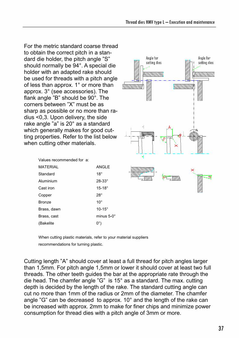
For the metric standard coarse thread to obtain the correct pitch in a stan-dard die holder, the pitch angle ”S” should normally be 94°. A special die holder with an adapted rake should be used for threads with a pitch angle of less than approx. 1° or more than approx. 3° (see accessories). The flank angle ”B” should be 90°. The corners between ”X” must be as sharp as possible or no more than ra-dius <0,3. Upon delivery, the side rake angle ”a” is 20° as a standard which generally makes for good cut-ting properties. Refer to the list below when cutting other materials.
Values recommended for a:
MATERIAL ANGLE
Standard 18°
Aluminium 28-33°
Cast iron 15-18°
Copper 28°
Bronze 10°
Brass, dawn 10-15°
Brass, cast minus 5-0°
(Bakelite 0°)
When cutting plastic materials, refer to your material suppliers
recommendations for turning plastic.
Cutting length ”A” should cover at least a full thread for pitch angles larger than 1,5mm. For pitch angle 1,5mm or lower it should cover at least two full threads. The other teeth guides the bar at the appropriate rate through the die head. The chamfer angle ”G” is 15° as a standard. The max. cutting depth is decided by the length of the rake. The standard cutting angle can cut no more than 1mm of the radius or 2mm of the diameter. The chamfer angle ”G” can be decreased to approx. 10° and the length of the rake can be increased with approx. 2mm to make for finer chips and minimize power consumption for thread dies with a pitch angle of 3mm or more.

38
6. Stoppage – Trouble shooting – Actions
Fault Cause Action
The machine does not start when pressing the start button.
The main switch is in the ”0” position.
Turn the main switch to the ”1” position.
The main fuse of the building is defective.
Inspect the electrical wirering, replace the main fuse.
The hydraulic unit and the coolant pump runs but the die head does not rotate at start up.
The knob for adjusting spindle revolutions is in –0 or max+ position.
Readjust the knob.
The machine has been overloaded. The electri-cal current limit of the frequency control has been exceeded.
Wait for the frequency control to reset or press ”reset” on the panel for the frequency control.(machine cabinet A1).
No coolant expelling from the coolant nozzle when the machine is operating.
The protective motor switch is in off-position (Enclosure 2 – F3)
Reset the protective motor switch.
Coolant level too low. Refill with coolant.
The filter of the coolant pump is clogged.
Clean the filter.
The hose connected to the coolant pump is da-maged.
Replace the hose.
The button for closing the clamp (S11) has not been depressed long enough.
Keep the button de-pressed for 1-2 se-conds after the workpi-ece is placed in the gripping jaws.
Hydraulic oil level too low.
Refill hydraulic oil(VG32 or VG46).
The surface of the bar consists of oxide scales or other impurities. The bar is not round.
Use a better shaped workpiece with a better surface.
The workpiece does not stay fixed in the clamp during threading.

39
Stoppage – Trouble shooting – Actions
Fault Cause Action
The workpiece does not stay fixed in the clamp during thread cutting.
The hydraulic pressure is too low.
Increase the hydraulic pressure by turning the adjustment screw un-der valve cap 230 (See enclosure 3). When the clamp is closed by pressing the S14 but-ton, the hydraulic pressure should be 60 - 80 bar.
Stop valve not functio-nal (See enclosure 3, valve 810).
Clean or replace the stop valve.
One of the dies is not correctly installed/centered.
Inspect the position of the thread dies by me-ans of the adjustment angle (see 3.2)
Incorrect cutting angle. Adjust the cutting angle according to the recom-mendations in enclosu-re 3.
The material of the workpiece is unsuitable for cutting machining.
Use material suitable for cutting machining.
The greasing properti-es of the coolant is un-suitable for the materi-al.
Use a coolant with gre-asing properties suitab-le for the material.
The profile of the thre-ad is incomplete.
The thread dies was installed in incorrect or-der.
Install the thread dies as instructed in section 3.2.
The thread is irregular and possibly has da-maged flanks and tops.

40
Fault Cause Action
The profile of the thre-ad is incomplete.
Thread dies from diffe-rent sets has been in-stalled.
Install thread dies from the same set.
The sled has been for-ce fed in incorrect rate.
Let the thread freely guide the sled after af-ter cutting 2 - 4 thre-ads. Make sure the sled travels with ease on the linear guide ways.
The threads are un-symmetrical.
The clamping dies are not centered to the die head.
Inspect the position of the clamping dies and adjust them heightwise if necessary. Inspect the position of the clamp on the sled and adjust it sideways if ne-cessary.
The workpiece is not sufficiently straight or round.
Use a sufficiently stra-ight/round workpiece.
The threads are tape-red.
The profile of the thre-ads might be incomple-te.
The spring that works to switch the adjust-ment ring and the die holders from opened to closed position is not stressed enough.
Adjust the prestress as instructed in section 3.1.
The spring that works to switch the adjust-ment ring and the die holders from opened to closed position is completely compres-sed to the bottom.
Replace the spring as instructed in section 3.1.
Stoppage – Trouble shooting – Actions

41
Accessories and equipment
There are several accessories and equipments available for thread cutting machine GM 07-100 SA. The machine as well as the accessories are under continuous development. If you want more information about the accessori-es or you if you want to place an order, please contact your HMV machines supplier or JBL Mekan AB.
7.1 Thread dies
Thread dies for metric coarse threads (per the swedish standard SS 1700, preference 1 and 2) for diameter 16 - 100mm are usually kept in stock by JBL Mekan AB. Several other thread dies for metric fine threads are also kept in stock.
Thread dies for inch threads (per the swedish standard SS 1713, preferen-ce 1 and 2) for diameter ¼” - 2” are usually kept in stock by JBL Mekan AB. Withworth pipe threads according to SS-ISO 228/1.
JBL Mekan AB can upon request produce thread dies for any threads, stan-dard or per your specification, for diameter 16 - 100mm.
All thread dies are constructed by high speed steel. A special coating that extends the life-span and better the performance of the dies is available as an option for all thread dies.
We also offer thread dies with two-step chamfering optimized for threading reinforcement bars.
Uncoated thread dies are most suitable for thread cutting of steel S235 - S355 and several other materials with properties suitable for cutting machi-ning at a max. cutting speed of 12m/min (Appropriate coolant must be used).
At any cutting speed, specially coated thread dies has a longer life-span. They can be used for thread cutting at cutting speeds up to 20m/min as long as an appropriate coolant is being used. Some materials have a ten-dency to stick to the cutting teeth. The special coating almost completely eliminates this problem.

42
Accessories and equipment
7.2 Grinding fixture HMV thread dies
The grinding fixture (option) is designed to be used primarily in standard tool– and surface grinders but can also be applied on ordinary grinding machines. It is essential to use the grinding fixture in order to achieve a precise sharpening. The drawing below illustrates how the grinding fixture is to be used with an ordinary grinding machine.
7.3 Die holders and for extreme pitch angles
Please contact JBL Mekan AB with your specifications.
The die holders are delivered with an installation instruction.

43
All our thread cutting machines are originally supplied with equipment for cutting right hand threads. Each machine can easily be adapted to cut left hand threads. We have special die holders, dies and setting template for left hand cutting available as an option. The die holders for left-hand thre-ads are delivered with an installation instruction.
The die head is equipped with a scale for left-hand threads and the direc-tion of the rotation of the die head is decided by the frequency control U1. When making left-hand threads, the die head rotates clockwise. The die head is made to rotate clockwise by moving the loop from DCM-M11 to DCN-M12 (see wiring diagram, section 9.3). When changing from right to left hand cutting, please proceed as follows: Detach die holder No. 1 and 2 from the die head by removing the screws (pos. 2). When removing the die holders, make sure that they are pulled straight out. Otherwise you may move the location pin (pos. 1) from it’s original position, causing difficulty when mounting the left hand die holders. Mount left die holder No. 1. Detach right die holder No. 3 and mount left die holder No. 2. Detach right die holder No. 4 and mount left die holder No. 3 and 4. When all four die holders have been exchanged, unscrew plugs (pos. 3) from the die head. One of these plugs is designed as a spring holder for the releasing spring. When cutting left hand threads, the releasing spring must work in opposite direction in which it works when cutting right hand threads. Switch the plugs so that the spring plug, complete with the spring occupies the position of the dummy plug and vice versa. When adjusting the spring tension, remember to not tightening the spring plug so hard that a space is formed between the rings of the die head when in it’s working position. When setting the left hand dies, please proceed in the same way as for right hand dies but use the special setting
template. Set the machine to cut left hand
threads by pressing F4 in menu VI. When left hand thread
cutting is enabled, the F4 indicator of menu VI is blank and the letter L is displayed in top right corner of menu I.
7.4 Die holders for left-hand threads
Accessories and equipment
1. Location pin 2. Screw 3. Adjustment screw spring release
2
1
3

44
Type of material, type of thread dies, type of coolant and operation se-quence should all be considered when selecting the cutting speed. Recommended cutting speeds Normally, materials S235 – S355 can be cut with speeds of 10 – 20m/min. It is recommended to use coated dies when cutting with speeds above ap-prox. 15m/min. Suitable cutting speeds for thread cutting are usually the same as suitable cutting speeds for coarse turning in the same material. Table: Spindle rpm – Cutting speed—diameter
Diameter Mm
100rm V m/min
360rm V m/min
V 10m/min Spindle rpm
V 15m/min Spindel rpm
V20m/min Spindel rpm
6 1,8 6,8 --------- ---------- ---------
8 2,5 9,0 --------- ---------- ---------
10 3,0 11,3 318 (90,8) ---------- ---------
12 3,8 13,6 265 (75,7) ---------- ---------
16 5,0 18,0 199 (56,8) 298 (85,1) ---------
20 6,2 22,6 159 (45,4) 238 (68,0) 318 (90,8)
24 7,5 27,1 132 (37,7) 199 (56,8) 265 (75,7)
27 8,5 30,5 118 (33,7) 176 (50,3) 235 (67,1)
30 9,5 33,9 106 (30,3) 159 (45,4) 212 (60,6)
33 10,3 37,3 96 (27,4) 144 (41,1) 193 (55,1)
36 11,3 40,7 88 (25,1) 132 (37,7) 176 (50,3)
39 12,2 44,1 81 (23,1) 122 (34,8) 163 (46,6)
42 13,2 47,5 75 (21,4) 113 (32,3) 151 (43,1)
45 14,0 50,9 70 (20,0) 106 (30,3) 141 (40,3)
48 15,0 54,3 66 (18,8) 100 (28,6) 132 (37,7)
Approx. Frequency U1 in parentheses (xx) 1Hz on frequency control U1 = 14 rpm on spindle Max spindle rotation speed 360rpm, 103Hz
8 Spindle rpm – Cutting speed—diameter

45
Enclosures
9.1 Enclosure 1 Handling

46
Enclosures
9.2 Enclosure 2 Wiring diagram—Connection
Hydraulic
unit
Spindle

47
Enclosures
9.3 Enclosure 3 Wiring diagram—PLC and control system
Spindle
(master)
Cover Spindle
Counter Counter
Distribution
Alarm
Alarm
H Unit

48
Enclosures
9.4 Enclosure 4 Wiring diagram cabinet A4 hydraulic unit

49
Enclosures
9.5 Enclosure 5 – Circuit diagram HYDAC Hybox flex mini
HYDAC Hybox Flex mini

50
____________________________________________________________________
____________________________________________________________________
____________________________________________________________________
____________________________________________________________________
____________________________________________________________________
____________________________________________________________________
____________________________________________________________________
____________________________________________________________________
____________________________________________________________________
____________________________________________________________________
____________________________________________________________________
____________________________________________________________________
____________________________________________________________________
____________________________________________________________________
____________________________________________________________________
____________________________________________________________________
____________________________________________________________________
____________________________________________________________________
____________________________________________________________________
____________________________________________________________________
____________________________________________________________________
____________________________________________________________________
____________________________________________________________________
____________________________________________________________________
____________________________________________________________________
____________________________________________________________________
____________________________________________________________________
____________________________________________________________________
____________________________________________________________________
____________________________________________________________________
____________________________________________________________________
____________________________________________________________________
____________________________________________________________________
____________________________________________________________________
____________________________________________________________________
____________________________________________________________________
____________________________________________________________________
____________________________________________________________________
Notes

51
____________________________________________________________________
____________________________________________________________________
____________________________________________________________________
____________________________________________________________________
____________________________________________________________________
____________________________________________________________________
____________________________________________________________________
____________________________________________________________________
____________________________________________________________________
____________________________________________________________________
____________________________________________________________________
____________________________________________________________________
____________________________________________________________________
____________________________________________________________________
____________________________________________________________________
____________________________________________________________________
____________________________________________________________________
____________________________________________________________________
____________________________________________________________________
____________________________________________________________________
____________________________________________________________________
____________________________________________________________________
____________________________________________________________________
____________________________________________________________________
____________________________________________________________________
____________________________________________________________________
____________________________________________________________________
____________________________________________________________________
____________________________________________________________________
____________________________________________________________________
____________________________________________________________________
____________________________________________________________________
____________________________________________________________________
____________________________________________________________________
____________________________________________________________________
____________________________________________________________________
____________________________________________________________________
____________________________________________________________________
____________________________________________________________________
____________________________________________________________________
____________________________________________________________________

52
JBL Mekan AB Lillesjövägen 19 570 83 Rosenfors Sverige Tel. +46(0) 495-208 40 Fax +46(0) 495-208-49 [email protected] www.jbl-mekan.se
hmvmachines.com