Embed Size (px)
Citation preview

11th Annual Electric Power Industry Conference
Swanson School of Engineering
Graduate Student Symposium
November 14th, 2016
Graduate Student Symposium
Session Moderator:
Dr. Brandon Grainger

11th Annual Electric Power Industry Conference
Swanson School of Engineering
Graduate Student Symposium
November 14th, 2016
Group 1 Analysis and Protection of Advanced Grids
Hashim Al Hassan, Rui Hu, Andrew Reiman, Matthieu Bertin, Joseph Petti

Protection and Distributed Control of Microgrids
Prepared by: Hashim Al Hassan
Ph.D. Student
11th Annual Electric Power Industry Conference
Swanson School of Engineering
Graduate Student Symposium
November 14th, 2016

Analysis and Protection of Advanced Grids
Protection and Distributed Control of Microgrid
Research Objective and Motivation
4
1. Fault Detection for renewable-energy based microgrids:
2. Secondary Control of Microgrids

Analysis and Protection of Advanced Grids
Protection and Distributed Control of Microgrid
Distributed Control Using Cooperative Control of Multi-Agent System Theory
5 Source: Bidram, Ali. "Distributed cooperative control of AC microgrids." (2014)

Analysis and Protection of Advanced Grids
Protection and Distributed Control of Microgrid
Microgrid Protection
6
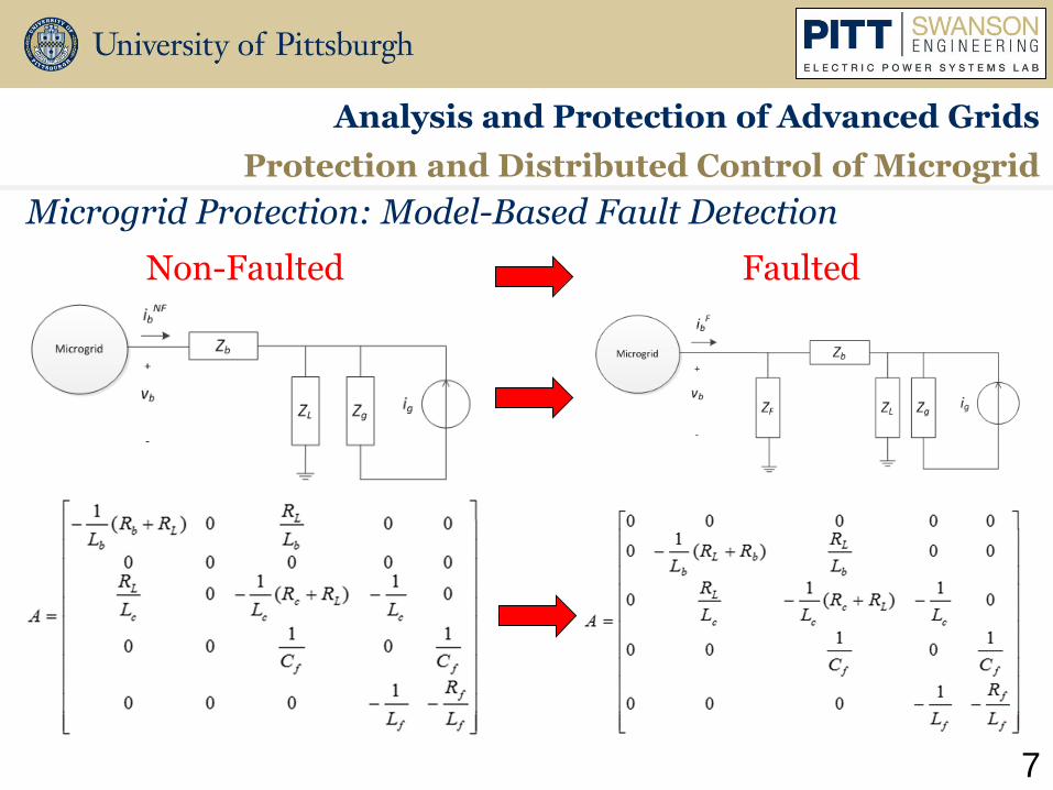
Analysis and Protection of Advanced Grids
Protection and Distributed Control of Microgrid
Microgrid Protection: Model-Based Fault Detection
7
Non-Faulted Faulted
Analysis and Protection of Advanced Grids
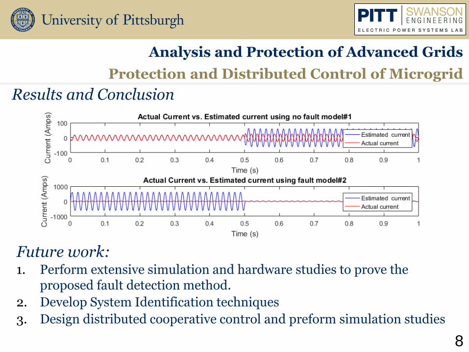
Future work: 1. Perform extensive simulation and hardware studies to prove the
proposed fault detection method.
2. Develop System Identification techniques
3. Design distributed cooperative control and preform simulation studies
Protection and Distributed Control of Microgrid
Results and Conclusion
8

Mixed Game Load Management Strategy For Wireless Communication Network Microgrid
Prepared by: Rui Hu
Ph.D Student
11th Annual Electric Power Industry Conference
Swanson School of Engineering
Graduate Student Symposium
November 14th, 2016
10
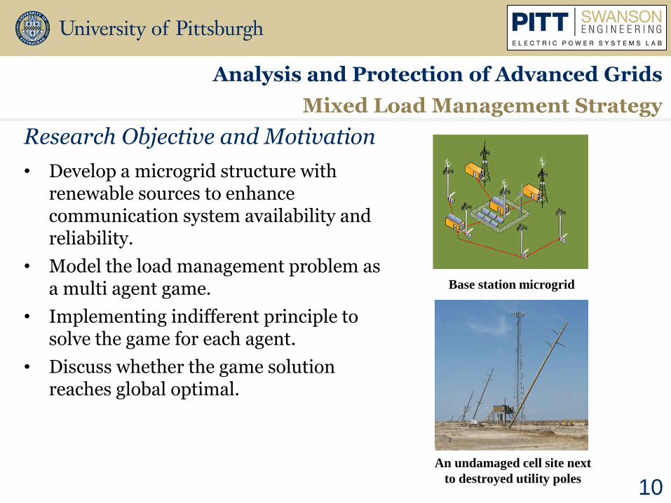
• Develop a microgrid structure with renewable sources to enhance communication system availability and reliability.
• Model the load management problem as a multi agent game.
• Implementing indifferent principle to solve the game for each agent.
• Discuss whether the game solution reaches global optimal.
Research Objective and Motivation
Analysis and Protection of Advanced Grids
Mixed Load Management Strategy
An undamaged cell site next
to destroyed utility poles
Base station microgrid
11
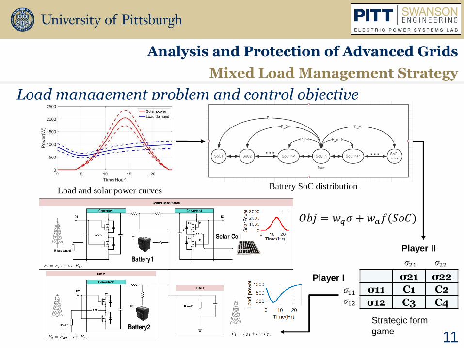
Load management problem and control objective
Analysis and Protection of Advanced Grids
Mixed Load Management Strategy
Player II
Player I
Strategic form
game
𝜎11 𝜎12
𝜎21 𝜎22
σ21 σ22
σ11 C1 C2
σ12 C3 C4
Load and solar power curves Battery SoC distribution
𝑂𝑏𝑗 = 𝑤𝑞𝜎 + 𝑤𝑎𝑓(𝑆𝑜𝐶)
12
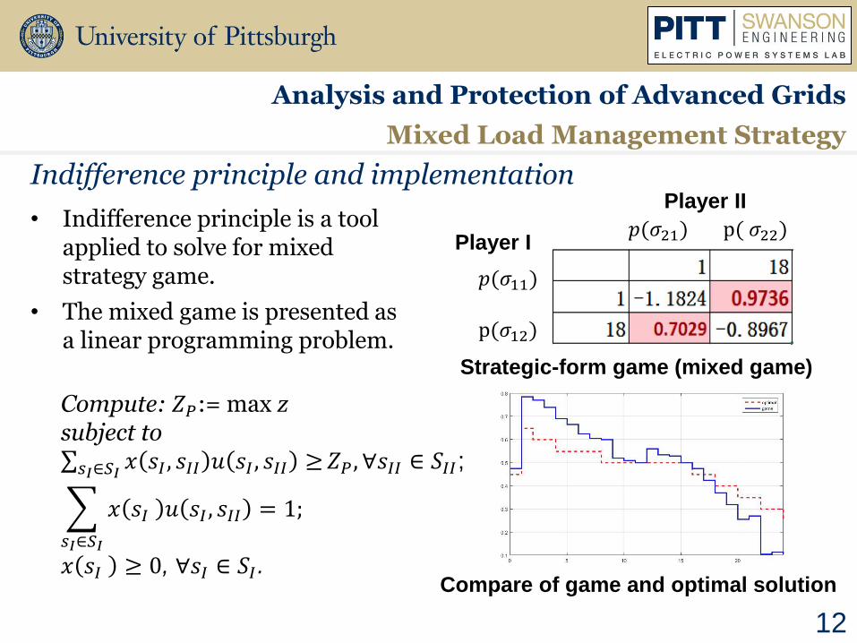
• Indifference principle is a tool applied to solve for mixed strategy game.
• The mixed game is presented as a linear programming problem.
Indifference principle and implementation
Analysis and Protection of Advanced Grids
Mixed Load Management Strategy
Player II
Player I
𝑝(𝜎11)
p(𝜎12)
𝑝(𝜎21) p( 𝜎22)
Strategic-form game (mixed game)
Compute: 𝑍𝑃:= max z subject to 𝑥 𝑠𝐼 , 𝑠𝐼𝐼 𝑢 𝑠𝐼 , 𝑠𝐼𝐼 ≥𝑠𝐼∈𝑆𝐼
𝑍𝑃, ∀𝑠𝐼𝐼 ∈ 𝑆𝐼𝐼;
𝑥 𝑠𝐼 𝑢 𝑠𝐼 , 𝑠𝐼𝐼 = 1;
𝑠𝐼∈𝑆𝐼
𝑥 𝑠𝐼 ≥ 0, ∀𝑠𝐼 ∈ 𝑆𝐼. Compare of game and optimal solution
13
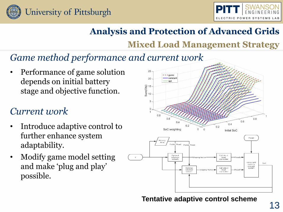
• Performance of game solution depends on initial battery stage and objective function.
• Introduce adaptive control to further enhance system adaptability.
• Modify game model setting and make ‘plug and play’ possible.
Game method performance and current work
Analysis and Protection of Advanced Grids
Mixed Load Management Strategy
Current work
Tentative adaptive control scheme
Distribution System Model Segmentation and Simplification
Prepared by: Andrew P. Reiman
Ph.D. Student
11th Annual Electric Power Industry Conference
Swanson School of Engineering
Graduate Student Symposium
November 14th, 2016

Load-FlowLoad-Flow
Control Logic
Load-Flow
Time-Series
Control Logic
Time-Series
15
QSTS simulation is a three-loop iterative procedure which can become computationally burdensome.
Analysis and Protection of Advanced Grids
Distribution System Model Segmentation and Simplification
• Hours per year: 8,760
• Seconds per day: 86,400
• Seconds per month: 2,592,000
• Seconds per year: 31,536,000
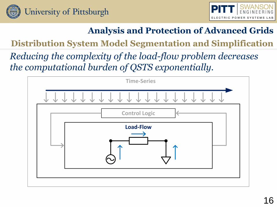
Load-Flow
Time-Series
Control Logic
16
Reducing the complexity of the load-flow problem decreases the computational burden of QSTS exponentially.
Analysis and Protection of Advanced Grids
Distribution System Model Segmentation and Simplification
17
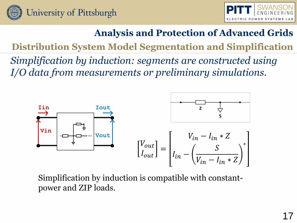
Simplification by induction: segments are constructed using I/O data from measurements or preliminary simulations.
Analysis and Protection of Advanced Grids
Distribution System Model Segmentation and Simplification
Vin
Iin
Vout
Iout
𝑉𝑜𝑢𝑡𝐼𝑜𝑢𝑡=
𝑉𝑖𝑛 − 𝐼𝑖𝑛 ∗ 𝑍
𝐼𝑖𝑛 −𝑆
𝑉𝑖𝑛 − 𝐼𝑖𝑛 ∗ 𝑍
∗
S
Z
Simplification by induction is compatible with constant-power and ZIP loads.
18
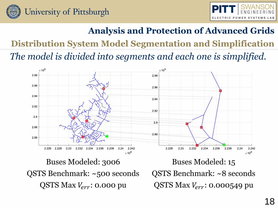
The model is divided into segments and each one is simplified.
Analysis and Protection of Advanced Grids
Distribution System Model Segmentation and Simplification
Buses Modeled: 3006
QSTS Benchmark: ~500 seconds
QSTS Max 𝑉𝑒𝑟𝑟: 0.000 pu
Buses Modeled: 15
QSTS Benchmark: ~8 seconds
QSTS Max 𝑉𝑒𝑟𝑟: 0.000549 pu

Methodology for Lightning Performance Improvement
Prepared by: Matthieu Bertin
M.S. Student
11th Annual Electric Power Industry Conference
Swanson School of Engineering
Graduate Student Symposium
November 14th, 2016
20
Project
Analysis and Protection of Advanced Grids
Methodology For Lightning Performance Improvement
• Main tool:
− OpenETran: software simulating lightning impacts on distribution lines
• Main tasks:
− C-language programming in OpenETran kernel to simulate a new physical model: Counterpoise
− Enhance user interface : Make interface & plots in Python v3
− Final documentation & soft deployment

21
Task 1: Counterpoise model implementation
Analysis and Protection of Advanced Grids
Methodology For Lightning Performance Improvement
• Counterpoise: Ground substitute for antennas, also grounding electrodes to reduce towers impulse resistance.

Task 1: Counterpoise model implementation
Analysis and Protection of Advanced Grids
Methodology For Lightning Performance Improvement
• Ancient model in OpenETran
• The model is linear
Source : “Effective length of counterpoise wire under lightning current”,
J. He, Y. Gao, R. Zeng, J. Zou, X. Liang, B. Zhang, J. Lee, S. Chang,
IEEE Transaction on Power delivery, Vol.20, No.2, APRIL 2005
• Counterpoise represented as a transmission line
• Leaked current Δi changes at each time step, making Ci & Gi change at each time step. The model is non linear

Task 1: Counterpoise model implementation
Analysis and Protection of Advanced Grids
Methodology For Lightning Performance Improvement
Previous Model
Counterpoise Model

Relay Panel Design for Microgrid Research Using Schweitzer Relays
Prepared by: Joseph J. Petti
M.S. Student
11th Annual Electric Power Industry Conference
Swanson School of Engineering
Graduate Student Symposium
November 14th, 2016
Purpose
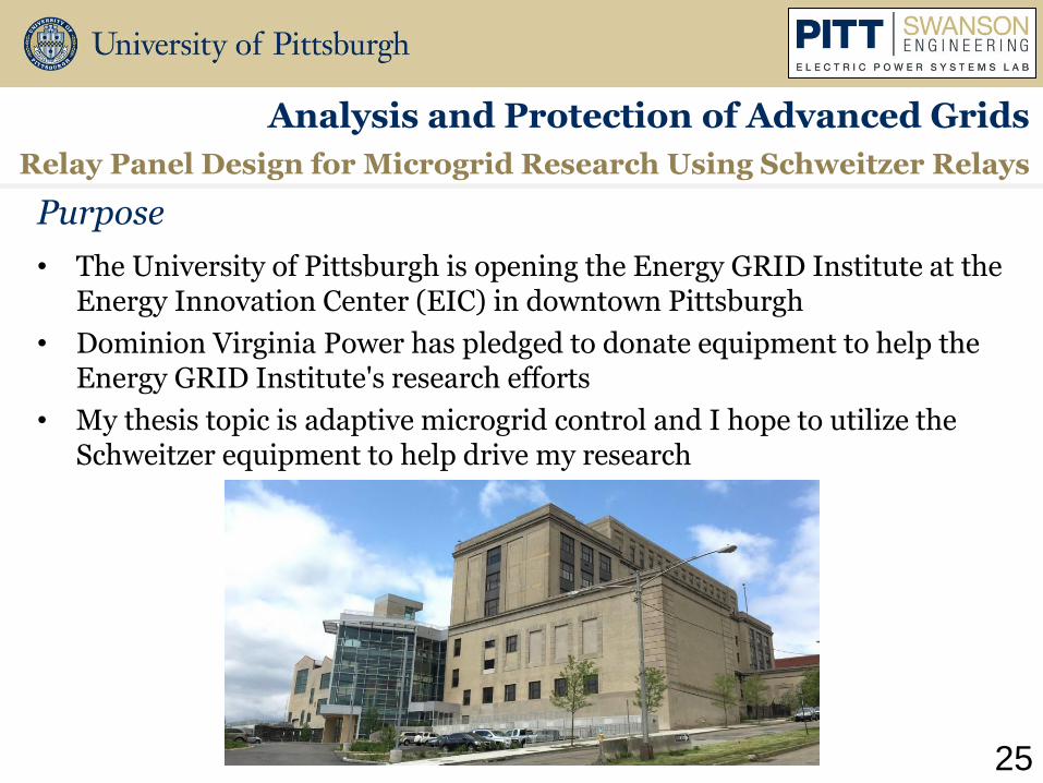
• The University of Pittsburgh is opening the Energy GRID Institute at the Energy Innovation Center (EIC) in downtown Pittsburgh
• Dominion Virginia Power has pledged to donate equipment to help the Energy GRID Institute's research efforts
• My thesis topic is adaptive microgrid control and I hope to utilize the Schweitzer equipment to help drive my research
25
Relay Panel Design for Microgrid Research Using Schweitzer Relays
Analysis and Protection of Advanced Grids

Schweitzer Equipment
• Schweitzer’s relays are known as the industry standard
• Utilities around the world use their relays to protect their systems
• A single Schweitzer digital relay can perform the tasks of 20 electromagnetic relays
26
Analysis and Protection of Advanced Grids
Relay Panel Design for Microgrid Research Using Schweitzer Relays

Features Useful For Micro Grid Research
• Fault location
• Precise metering
− Voltage, Current, Phasors, PF, Sequence Components
• Load shedding
• Communication
• Custom logic capabilities
27
Analysis and Protection of Advanced Grids
Relay Panel Design for Microgrid Research Using Schweitzer Relays
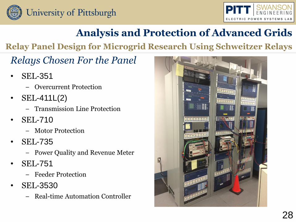
Relays Chosen For the Panel
• SEL-351
− Overcurrent Protection
• SEL-411L(2)
− Transmission Line Protection
• SEL-710
− Motor Protection
• SEL-735
− Power Quality and Revenue Meter
• SEL-751
− Feeder Protection
• SEL-3530
− Real-time Automation Controller
28
Analysis and Protection of Advanced Grids
Relay Panel Design for Microgrid Research Using Schweitzer Relays

Andrew Bulman, Samantha Morello,
Santino Graziani, Laura Weiserman
11th Annual Electric Power Industry Conference
Swanson School of Engineering
Graduate Student Symposium
November 14th, 2016
Group 2 Implementation of Microgrids and Transient Protection Systems

Microgrid Case Study Analysis
Prepared by: Andrew R. Bulman
M.S. Student
11th Annual Electric Power Industry Conference
Swanson School of Engineering
Graduate Student Symposium
November 14th, 2016

Project Overview
Microgrid Case Study Analysis
31
• Performing case studies on microgrid projects in the Pittsburgh region, in conjunction with the Pittsburgh District Energy Initiative, to analyze a variety of impacts of microgrids.
• A key goal is to gain a better understanding of how to take into account the non-economic factors to evaluate potential microgrid project in the Pittsburgh region.
Implementation of Microgrids and Transient Protection Systems

Case Studies: Millvale and Chatham University
Microgrid Case Study Analysis
32
• The University of Pittsburgh was asked to take the lead in a performing feasibility study of a 1.459 acre site owned by Millvale that could be a potential site of the solar farm and/or microgrid.
• Joint collaboration with Chatham University, Duquesne Light, and the University of Pittsburgh to investigate a potential microgrid project at the Eden Hall Campus.
Implementation of Microgrids and Transient Protection Systems

Case Study: Pitt Ohio
Microgrid Case Study Analysis
33
• Project is almost completed and ready for final commissioning.
• Goal was to create a viable system architecture for integrating the existing AC power system with renewable energy resources (50 kW of solar power and 5 kW of wind power) distributed through a 380 Vdc backbone.
Implementation of Microgrids and Transient Protection Systems
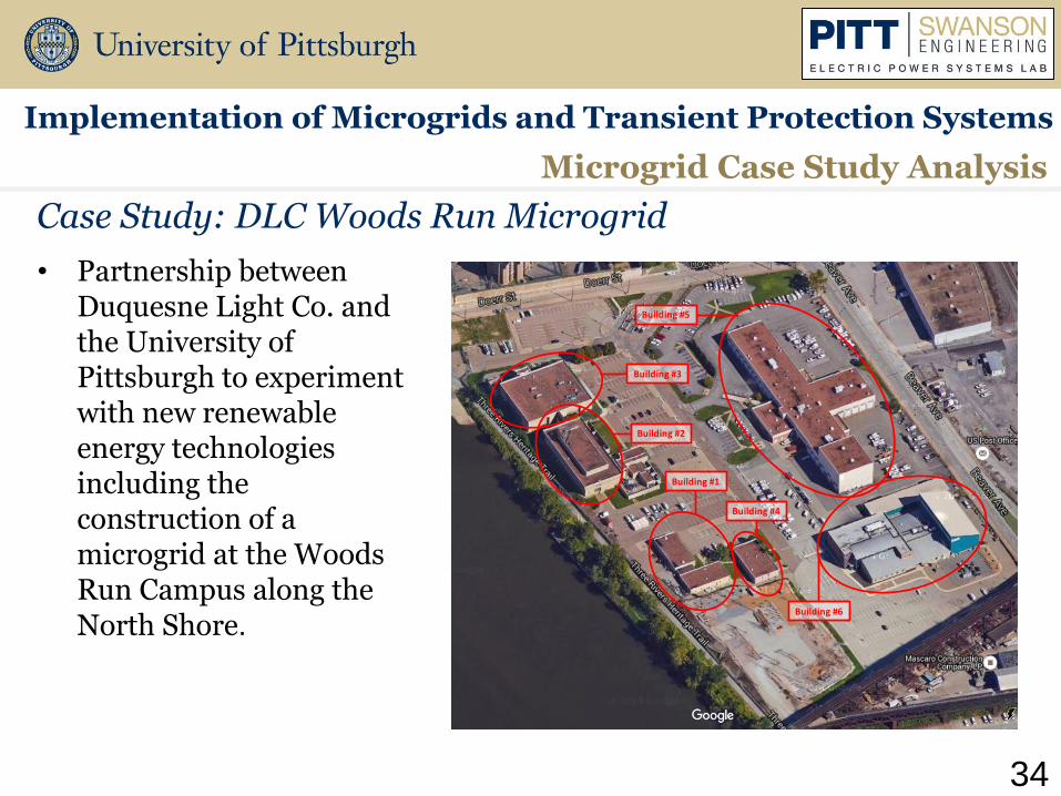
Case Study: DLC Woods Run Microgrid
Microgrid Case Study Analysis
34
Building #3
Building #2
Building #5
Building #1
Building #4
Building #6
• Partnership between Duquesne Light Co. and the University of Pittsburgh to experiment with new renewable energy technologies including the construction of a microgrid at the Woods Run Campus along the North Shore.
Implementation of Microgrids and Transient Protection Systems

Energy Initiative for the Build Out and Optimization of Pittsburgh's Electrical Infrastructure
Prepared by: Samantha A. Morello
M.S. Student
11th Annual Electric Power Industry Conference
Swanson School of Engineering
Graduate Student Symposium
November 14th, 2016
36
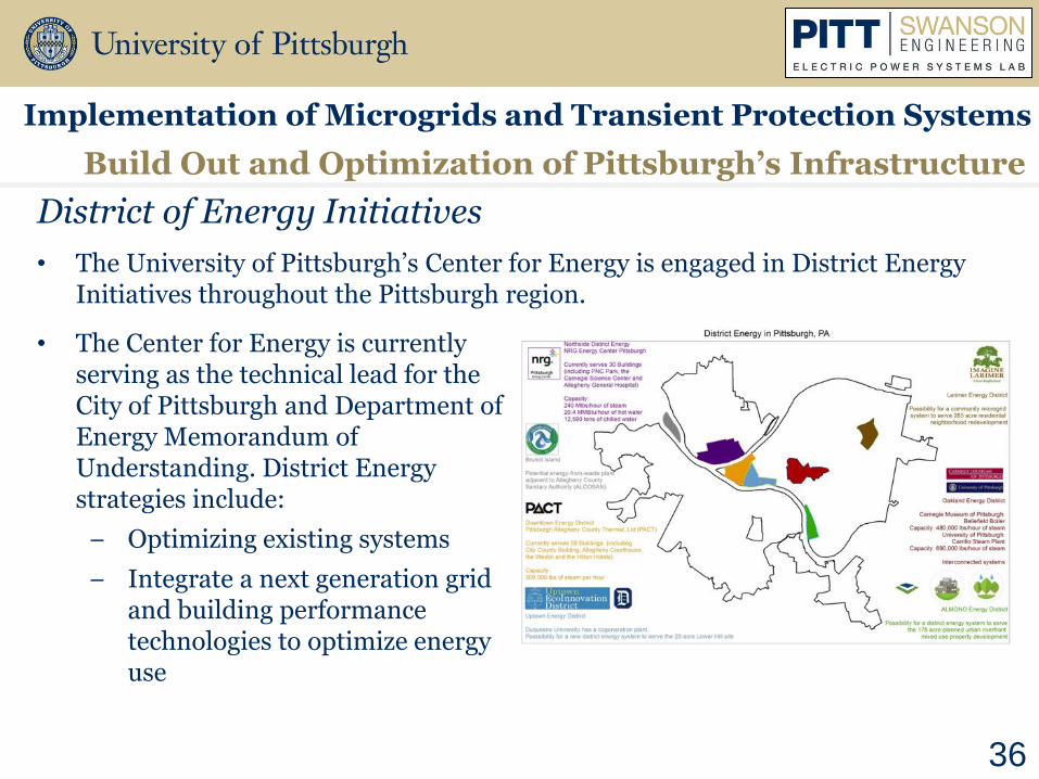
• The University of Pittsburgh’s Center for Energy is engaged in District Energy Initiatives throughout the Pittsburgh region.
District of Energy Initiatives
Build Out and Optimization of Pittsburgh’s Infrastructure
• The Center for Energy is currently serving as the technical lead for the City of Pittsburgh and Department of Energy Memorandum of Understanding. District Energy strategies include:
− Optimizing existing systems
− Integrate a next generation grid and building performance technologies to optimize energy use
Implementation of Microgrids and Transient Protection Systems
37
Build Out and Optimization of Pittsburgh’s Infrastructure
Overview
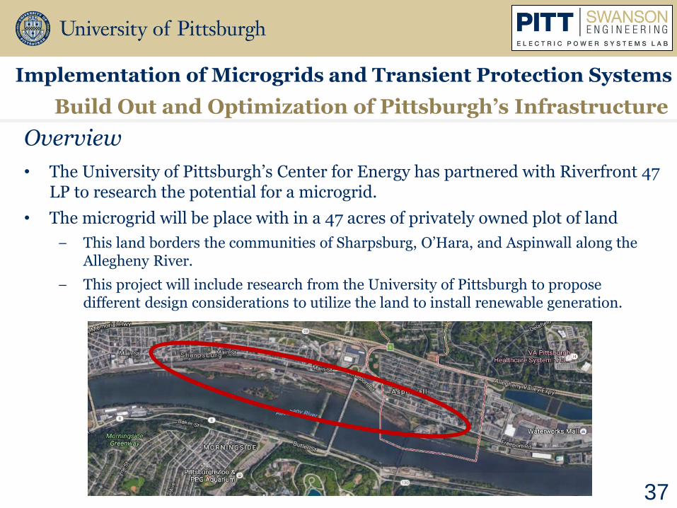
• The University of Pittsburgh’s Center for Energy has partnered with Riverfront 47 LP to research the potential for a microgrid.
• The microgrid will be place with in a 47 acres of privately owned plot of land
− This land borders the communities of Sharpsburg, O’Hara, and Aspinwall along the Allegheny River.
− This project will include research from the University of Pittsburgh to propose different design considerations to utilize the land to install renewable generation.
Implementation of Microgrids and Transient Protection Systems
38
Build Out and Optimization of Pittsburgh’s Infrastructure
The University of Pittsburgh’s Role
• Conduct a topline microgrid feasibility study through the use of modeling software
• The scope of work for this project will include:
− Different design scenarios and analysis for a usable microgrid
− Islanded and grid connected designs
− A feasibility study of the land and where certain renewable generations would be best placed
− A cost analysis of the proposed designs
− Emissions footprint
− Amount of area the design will occupy per requested amount of power generation
− Generation produced per month at PV/wind location.
Implementation of Microgrids and Transient Protection Systems

39
Build Out and Optimization of Pittsburgh’s Infrastructure
HOMER Energy Software
• HOMER (Hybrid Optimization of Multiple Energy Resources) Energy is a software company which specializes in microgrid analysis and design.
• Software capabilities:
− Emissions percentages that the system releases into the atmosphere per year
− Net present cost based on load and generation selected for the design (grid connected or islanded)
− Total footprint that components will occupy
− Time series analysis of the system. This meaning the total amount of energy the components will generate per month
− Determine the maximum amount of renewable penetration of the system
Implementation of Microgrids and Transient Protection Systems

OpenDSS Model for Analysis of Photovoltaic Inverter Transients: Testing
Prepared by: Santino F. Graziani
M.S. Student
11th Annual Electric Power Industry Conference
Swanson School of Engineering
Graduate Student Symposium
November 14th, 2016

41
Implementation of Microgrids and Transient Protection Systems
OpenDSS Model for Analysis of Photovoltaic Inverter Transients
Inverter Transient Testing Using EPRI PortoSag Generator
42
Single-Phase Inverter
Single-Phase Inverter
Single-Phase Inverter
Micro-Inverter
OpenDSS Model for Analysis of Photovoltaic Inverter Transients
Implementation of Microgrids and Transient Protection Systems
Open-Circuit Event Data
Single-Phase Inverter
Single-Phase Inverter
Micro-Inverter Three-Phase Inverter
OpenDSS Model for Analysis of Photovoltaic Inverter Transients
Implementation of Microgrids and Transient Protection Systems
Short-Circuit Event Data
43
OpenDSS Model for Analysis of Photovoltaic Inverter Transients: Modeling
Prepared by: Laura M. Wieserman
Ph.D. Student
11th Annual Electric Power Industry Conference
Swanson School of Engineering
Graduate Student Symposium
November 14th, 2016
45
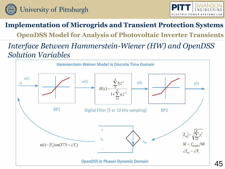
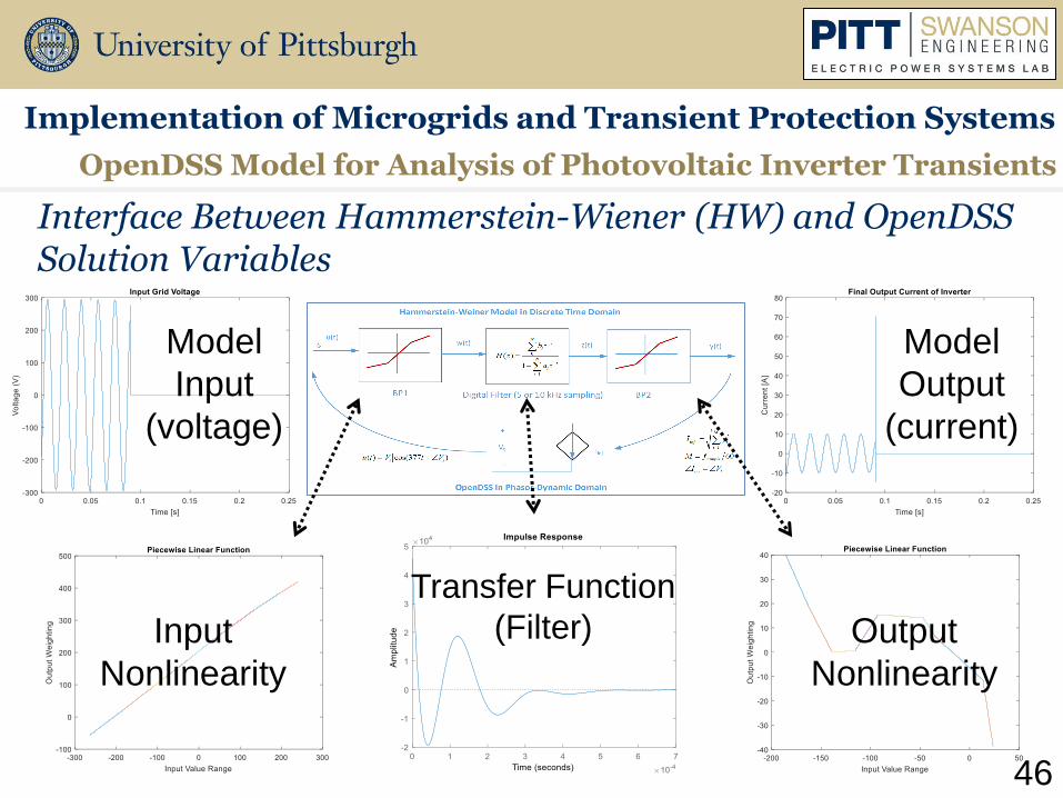
OpenDSS Model for Analysis of Photovoltaic Inverter Transients
Implementation of Microgrids and Transient Protection Systems
Interface Between Hammerstein-Wiener (HW) and OpenDSS Solution Variables
46
Model
Input
(voltage)
Model
Output
(current)
Input
Nonlinearity
Output
Nonlinearity
Transfer Function
(Filter)
OpenDSS Model for Analysis of Photovoltaic Inverter Transients
Implementation of Microgrids and Transient Protection Systems
Interface Between Hammerstein-Wiener (HW) and OpenDSS Solution Variables
47
OpenDSS Snapshot
Lab Data
Model Output
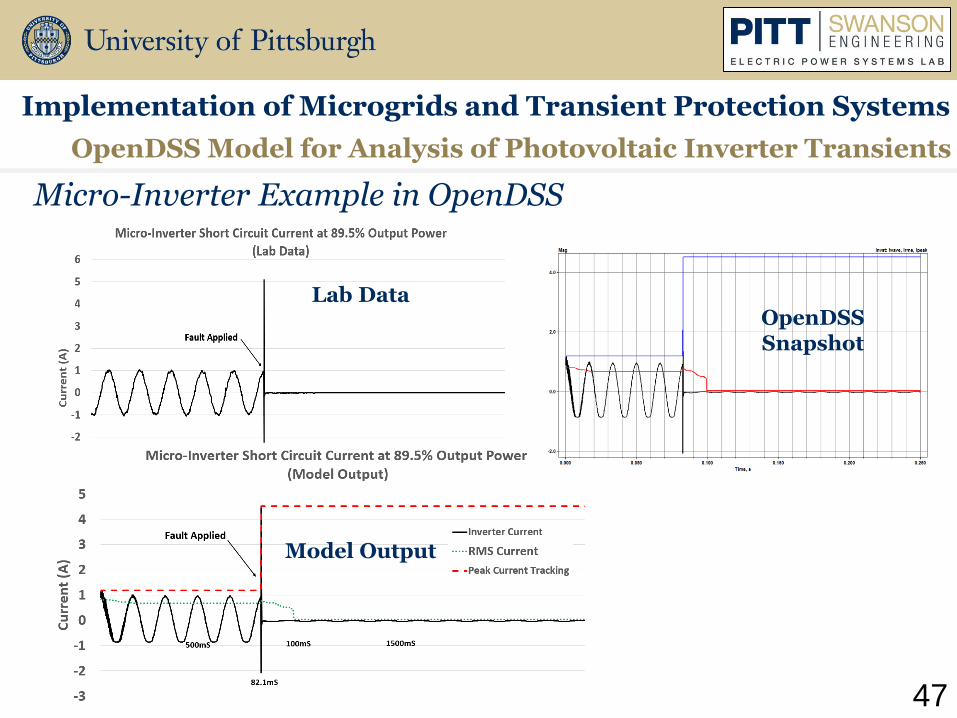
OpenDSS Model for Analysis of Photovoltaic Inverter Transients
Micro-Inverter Example in OpenDSS
Implementation of Microgrids and Transient Protection Systems
48
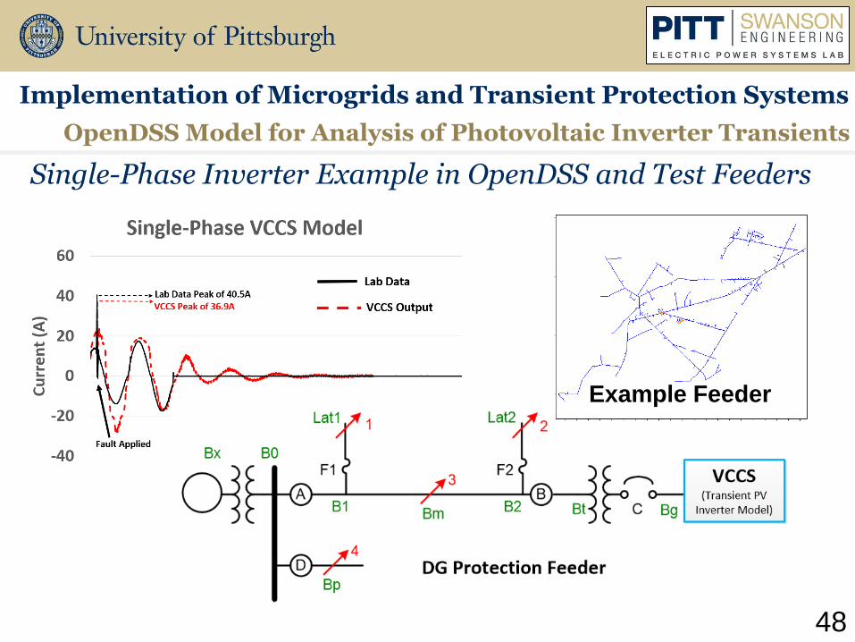
Example Feeder
Single-Phase Inverter Example in OpenDSS and Test Feeders
OpenDSS Model for Analysis of Photovoltaic Inverter Transients
Implementation of Microgrids and Transient Protection Systems

Group 3 Design and Analysis of Power Electronic Converters
11th Annual Electric Power Industry Conference
Swanson School of Engineering
Graduate Student Symposium
November 14th, 2016
Ansel Barchowsky, Alvaro Cardoza, Jacob Friedrich, Chris Scioscia, Patrick Lewis

Modular, Multilevel, High Density DC-DC and DC-AC Converters using GaN HFETs
Prepared by: Ansel Barchowsky
Ph.D. Student
11th Annual Electric Power Industry Conference
Swanson School of Engineering
Graduate Student Symposium
November 14th, 2016

51
Why GaN MMCs?
Design and Analysis of Power Electronic Converters
Modular Multilevel GaN Converters
• The Objective
• Use GaN HFETs to achieve high density and efficiency in DC-DC and DC-AC conversion
• The Challenge
• Commercially available GaN HFETs are limited to about 650 V, 100 A
• The Solution – MMC
• Divides applied voltage across multiple submodules
• Extremely efficient and low volume requirements
EPC2014C eGaN HEMT
1.1 mm
1.7 mm
Single submodule test board

52
DC-AC Converter Design
Design and Analysis of Power Electronic Converters
Modular Multilevel GaN Converters
Proposed DC-AC MMC structure
• Converter specifications:
• 450 VDC input, 240 VAC output, 2 kVA
• Output AC frequency of 60 Hz
• Switching frequency of 16 kHz
• Phase shifted pulse width modulation
• 14 submodules per arm using EPC 2014c devices and 1.6 mF capacitors
• Converter achievements:
• Peak simulated efficiency of 98%
• Less than 5% THD with only 1 µH arm inductor
• 100 W/in3 power to volume ratio
Vin
Cin
Cin
Lb Lb
Lb Lb
Vout
+
-
Low Voltage 1ph M2C Bridge:14 Level EPC2014c
Low Voltage 1ph M2C Bridge:14 Level EPC2014c

53
DC-AC Converter Design
Design and Analysis of Power Electronic Converters
Modular Multilevel GaN Converters
Proposed 1ph MMC structure
• Converter specifications:
• 200 VDC input, 600 VDC output
• AC tank frequency of 1 MHz
• Switching frequency of 1 MHz
• Nearest level QSW modulation
• 4 SM per input arm, 10 SM per output arm using EPC2016c HFETs
• Converter achievements:
• PCB-integrated planar ferrite transformer
• Efficiency up to 84% at 1 MHz
• 120 W/in3 power to volume ratio
Vin
Cin
Cin
Lb Lb
Lb Lb
VAC1
+
-
Low Voltage 1ph M2C Bridge:4 Level EPC2016c
Vout
Cout
Cout
LbLb
LbLb
VAC2
+
-
High Voltage 1ph M2C Bridge:10 Level EPC2016c
HF Transformer

54
Hardware Prototyping
Design and Analysis of Power Electronic Converters
Modular Multilevel GaN Converters
Top and side view of MMC arm PCB
• Initial prototype Design:
• 14 SM DC-AC arm board under development
• 4 arm PCBs form full converter
• Initial low voltage testing underway
2-level output voltage of single arm test

Power Source Buffering using a Triangular Modular Multilevel Converter with Energy Storage
Prepared by: Alvaro Cardoza
PhD Student
11th Annual Electric Power Industry Conference
Swanson School of Engineering
Graduate Student Symposium
November 14th, 2016
56
Background/Motivation
Sources: http://www.wfs.org/futurist/july-august-2012-vol-46-no-4/smart-house-networked-home
http://www.stratacore.com/the-advisor/data-center-providers-ma-activity-2015
Design and Analysis of Power Electronic Converters
Power Source Buffering using a TMMC with Energy Storage
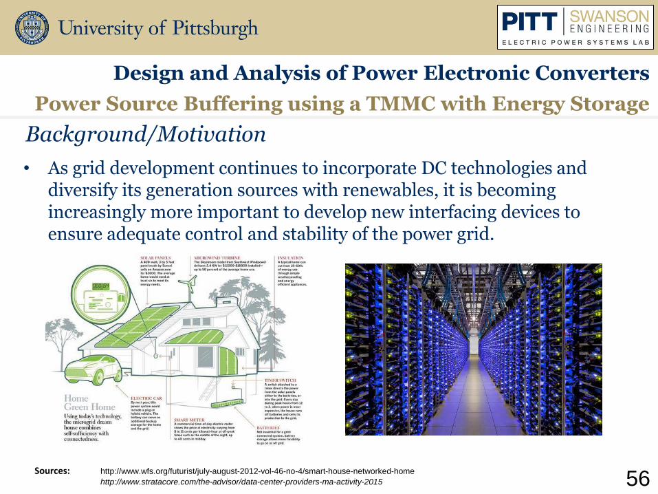
• As grid development continues to incorporate DC technologies and diversify its generation sources with renewables, it is becoming increasingly more important to develop new interfacing devices to ensure adequate control and stability of the power grid.

57
Full Testbed System
TMMC with Energy Storage and PV source
0
0
IndCurrent_3_1
IndCurrent_2_2
IndCurrent_1_1 Ind_Current1_2 IndCurrent_1_3
IndCurrent_2_1
GAIN
Voltage_Controller1_Kp
I
Voltage_Controller1_Ki
VC1_out
21.844
VSUM_row1
189.86Vref1_SUM
0.13809
Vref2_SUM
-3.3677
VSUM_row2
193.37
CONST
V_ref1
IND_MEASURE_2_1
0
IND_MEASURE_1_1-0.1366
-0.1366
IND_MEASURE_1_2
GAIN
Voltage_Controller2_Kp
I
Voltage_Controller2_Ki
VC2_out
2.9071
CONST
V_ref2 TPH1
TPH3
TPH2
VC1_out1
50.428
IND_MEASURE_1_5
28.573
IND_MEASURE_1_4
28.573
TPH6
TPH5
GAIN
Voltage_Controller1_Kp1
I
Voltage_Controller1_Ki1
VSUM_row3
186.29Vref1_SUM1
3.7121
CONST
V_ref3
IND_MEASURE_1_3
28.573
C9
TPH4
C10C11
+
V
V_input1
0
+
V
Vctrl_input
-380
R2
380
126.67
E1
Vctrl_Step
EC1
11.026
0
Vout_pos
CapVoltage_3_1
IndCurrent_3_1
Vin_pos_Vout_neg Vin_neg
U1
TMMC Submodule1
Vout_pos
CapVoltage_2_1
IndCurrent_2_1
Vin_pos_Vout_neg Vin_neg
U2
TMMC Submodule2
Vout_pos
CapVoltage_2_2
IndCurrent_2_2
Vin_pos_Vout_neg Vin_neg
U3
Vout_pos
CapVoltage_1_1
IndCurrent_1_1
Vin_pos_Vout_neg Vin_neg
U4
TMMC Submodule4
Vout_pos
CapVoltage_1_2
IndCurrent_1_2
Vin_pos_Vout_neg Vin_neg
U5
TMMC Submodule5
Vout_pos
CapVoltage_1_3
IndCurrent_1_3
Vin_pos_Vout_neg Vin_neg
U6
+
V
Vcap_row3
97.563
+V
Vcap_row2
95.805
+V
Vcap_row1
94.057
R1
92.231
A
AM1
0
A
AM2
0
A
AM3
0
STATE_33_1
TRANS8TRANS7
TRANS6TRANS5
STATE_11_6
STATE_11_5
C1
UC_Discharge_3_1
0
L7
UC_Charge_3_1
0
R5
+
V
Vucap_row3
47.998
Rf1
D13
D14
PWM
PWM1
D2
D3
Rf2
+
V
Vucap_row1
47.998
R3
UC_Charge_3_2
0
L1
UC_Discharge_3_2
0
C2
D4
D5
Rf3
+
V
Vucap_row2
47.998
R4
UC_Charge_3_3
0
L2
UC_Discharge_3_3
0
C3
C4
UC_Discharge_3_4
0
L3
UC_Charge_3_4
0
R6
+
V
Vucap_row4
47.998
Rf4
D6
D7
C5
UC_Discharge_3_5
0
L4
UC_Charge_3_5
0
R7
+
V
Vucap_row5
47.998
Rf5
D8
D9
C6
UC_Discharge_3_6
0
L5
UC_Charge_3_6
0
R8
+
V
Vucap_row6
47.998
Rf6
D10
D11
STATE_11_1
STATE_11_2
TRANS1 TRANS2
TRANS3TRANS4
STATE_33_2
STATE_11_3
STATE_11_4
TRANS9 TRANS10
TRANS11TRANS12
STATE_33_3
L8
EQU
IF (Time<=0.25)
{ Rload:=2.12; } ELSE
{ Rload:=2.12*1; }
W +
WM4
S4
S3
Rd
0
Lf0
Cf
0
PVout+
PVout-
TotalPVSystem
PV, Boost, & BB Reg
PV_Disconnect
W
+
WM5
PV Input 1747 W, 1000 W/m2
Module 3,1
Module 2,1
Module 2,2
Module 1,1
Module 1,2
Module 1,3
PI Controllers
Hysteresis Current
Controllers
sESS 3,1
sESS 2,1 sESS 2,2
sESS 1,1 sESS 1,2 sESS 1,3
3rd Row sESS State Machine
2nd Row sESS State Machine
1st Row sESS State Machine
“Grid” Input
“Load” Output
Design and Analysis of Power Electronic Converters
Power Source Buffering using a TMMC with Energy Storage
58
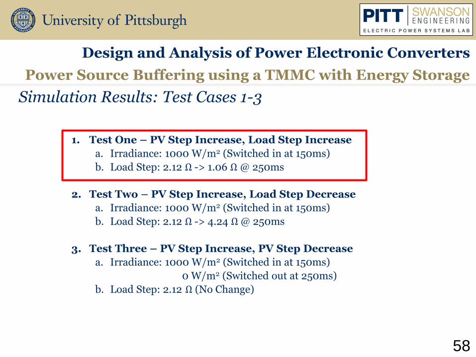
Simulation Results: Test Cases 1-3
1. Test One – PV Step Increase, Load Step Increase
a. Irradiance: 1000 W/m2 (Switched in at 150ms)
b. Load Step: 2.12 Ω -> 1.06 Ω @ 250ms
2. Test Two – PV Step Increase, Load Step Decrease
a. Irradiance: 1000 W/m2 (Switched in at 150ms)
b. Load Step: 2.12 Ω -> 4.24 Ω @ 250ms
3. Test Three – PV Step Increase, PV Step Decrease
a. Irradiance: 1000 W/m2 (Switched in at 150ms)
0 W/m2 (Switched out at 250ms)
b. Load Step: 2.12 Ω (No Change)
Design and Analysis of Power Electronic Converters
Power Source Buffering using a TMMC with Energy Storage

59
Test 1 – PV System Switched-In and Load Increase
With Ultracapacitor ESS Without Ultracapacitor ESS
With Ultracapacitor ESS Without Ultracapacitor ESS
118.5 V
55.5 V 106.9 V
71.4 V
Design and Analysis of Power Electronic Converters
Power Source Buffering using a TMMC with Energy Storage
• Irradiance: 1000 W/m2 (Switched in at 150 ms)
• Load Step: 2.12 Ω -> 1.06 Ω @ 250 ms

60
Test 1 – PV System Switched-In and Load Increase
With Ultracapacitor ESS Ultracapacitor ESS Current Injection
Design and Analysis of Power Electronic Converters
Power Source Buffering using a TMMC with Energy Storage

Quantifying DC Electric Ship Performance and Emission Reductions through Modular, Integrated Resonance Units with Parallel Energy Storage
Prepared by: Jacob H Friedrich
M.S. Student
11th Annual Electric Power Industry Conference
Swanson School of Engineering
Graduate Student Symposium
November 14th, 2016

62
• Navy Sea System Command states the design philosophy is as follows:
“The primary aim of the electric power system design will be for survivability and continuity of the electrical
power supply.”
Research Motivation and Objective
Design and Analysis of Power Electronic Converters
Quantifying DC Electric Ship Performance and Emission Reductions
• Based on Naval Ship study:
− Fault identification
− Integrate energy storage with series resonate converter
− Evaluate behavior of the modular unit
− Quantify the expected emission profiles for DC based ship

63
Fault Identification
Design and Analysis of Power Electronics Converters
~- G
~- M
~
G
-
- - - - - -
- - - - - -
Vital Load -~
Load
- - - - - -
- - - - - -
-~
Load
Vital Load
DC/DC Converters DC/DC Converters
DC/DC ConvertersDC/DC Converters
MVDC Starboard
Bus
Port Propulsion
Motor
~ M
-
Auxiliary AC
Generator
AC Breaker
DC Cable
Overhead
Line
Auxiliary AC
Generator
AC Breaker
Inverter Drive
Inverter Drive
DC
Disconnect
DC
Disconnect
DC Cable
Overhead
Line
N
N
Line-to-Line
Fault
Line-to-Ground
Fault
1
2
3
4
5
6
7
8
910
11
12
13
14
15
Ship Architecture Layout and Fault Locations
Quantifying DC Electric Ship Performance and Emission Reductions
• Determine a system characteristic signature for fault section identification
• The focus for the core simulation analysis will be on current and voltage profiles before, during, and after a contingency event throughout one zone of an electric ship

64
• Input voltage increases the efficiency profile and keeps its general form but translates to a lower efficiency
• The maximum efficiency can be reached by adjusting the equivalent load that the SRC processes
Series Resonate Converter
Design and Analysis of Power Electronic Converters
SRC performance over specified load range for
varying input voltages
System Overview
Quantifying DC Electric Ship Performance and Emission Reductions

65
• Study needs to be done to ensure that the modular integrated storage architecture can handle the expected mechanical thermal stresses with dynamic load changes
• A design criteria for optimal performance or stable operation can be seen in the image
Power Semiconductor Reliability
Design and Analysis of Power Electronic Converters
Ramp Rate Guidelines
Quantifying DC Electric Ship Performance and Emission Reductions

66
• Under Executive Order, emissions need reduced and energy performance needs to be increased
• Maritime transport emits roughly 1000 million tons of CO2 annually
• Emissions produced by power production process will be analyzed compared to emissions produced by engine fuel consumption
• Holistic assessment and comparison of lifecycle
Emission Profiles for DC Based Ship
Design and Analysis of Power Electronic Converters
Quantifying DC Electric Ship Performance and Emission Reductions

Supplementing Resonant Converter Performance with Parallel Energy Storage
Prepared by: Christopher Scioscia
M.S. Student
11th Annual Electric Power Industry Conference
Swanson School of Engineering
Graduate Student Symposium
November 14th, 2016

68
• Photovoltaics generation continues to penetrate the electric market
• Energy storage required due to intermittency
• Ability of energy storage to supplement the performance of an individual converter
• Additional benefits of power rerouting, load sharing, reliability, and operational flexibility
Research Motivation
Design and Analysis of Power Electronic Converters
Resonant Converter Performance with Parallel Energy Storage
DC system overview

69
• Improved performance over wider range of loads
• Efficiency profile for converter hill shaped
• Top curve at 90 V input, bottom curve at 150 V input
• Assistance sinks or sources current from front and or back to improve performance
Battery Assisted Performance
Design and Analysis of Power Electronic Converters
Resonant Converter Performance with Parallel Energy Storage
SRC efficiency versus load range
Solar Array
Resonant Converter
Load
Energy Storage
89
90
91
92
93
94
95
96
0 500 1000 1500 2000 2500 3000 3500
Effi
cien
cy (%
)
Power Processed (W)
Converter Load Profile
90 V
100 V
110 V
150 V
Back Assist
Front Assist

70
• Operating at light load efficiency
• Algorithm converges on current that results in optimal efficiency
• Improves unassisted efficiency from 83.8% to 90.5%
Back End Support
Design and Analysis of Power Electronic Converters
Resonant Converter Performance with Parallel Energy Storage
Resonant Converter
Storage
89.5
90
90.5
91
91.5
92
92.5
93
93.5
94
0 500 1000 1500 2000 2500 3000 3500
Eff
icie
nc
y (
%)
Power Processed (W)
Converter Load Profile
Light Load
SRC Power Processed
SRC Efficiency

71
• Operating with heavy insolation, high input voltage
• Algorithm sinks current to reduce input voltage to target threshold, 90V
• Improves unassisted efficiency from 83.8% to 92%
Back End Support
Design and Analysis of Power Electronic Converters
Resonant Converter Performance with Parallel Energy Storage
89
90
91
92
93
94
95
96
0 500 1000 1500 2000 2500 3000 3500
Effi
cien
cy (%
)
Power Processed (W)
Converter Load Profile
90 V
150 VHigh Irradiance
Resonant Converter
Storage
SRC Front Voltage
SRC Efficiency

72
• Algorithm realized within greater mode hierarchy
• Autonomous assistance, load sharing, and voltage support
Mode Hierarchy
Design and Analysis of Power Electronic Converters
Resonant Converter Performance with Parallel Energy Storage
Mode Transition States
𝑀𝑜𝑑𝑒 𝐼 𝐵𝑎𝑡𝑡𝑒𝑟𝑦 𝑆𝑡𝑎𝑛𝑑𝑏𝑦
𝑀𝑜𝑑𝑒 𝐼𝐼 𝐵𝑎𝑡𝑡𝑒𝑟𝑦 𝐴𝑠𝑠𝑖𝑠𝑡
𝑀𝑜𝑑𝑒 𝐼𝐼𝐼 𝐵𝑎𝑡𝑡𝑒𝑟𝑦 𝐶ℎ𝑎𝑟𝑔𝑒
𝑀𝑜𝑑𝑒 𝐼𝑉 𝐵𝑎𝑡𝑡𝑒𝑟𝑦 𝐷𝑖𝑠𝑐ℎ𝑎𝑟𝑔𝑒
𝑀𝑜𝑑𝑒 𝑉 𝐵𝑎𝑡𝑡𝑒𝑟𝑦 𝐸𝑚𝑝𝑡𝑦 𝑆𝑡𝑎𝑛𝑑𝑏𝑦

Inverter Grid Support and Electro-Thermal Device Analysis in Microgrids
Prepared by: Patrick T. Lewis
Ph.D. Student
11th Annual Electric Power Industry Conference
Swanson School of Engineering
Graduate Student Symposium
November 14th, 2016
Inverter Grid Support and Electro-Thermal Analysis in Microgrids
Research Motivation
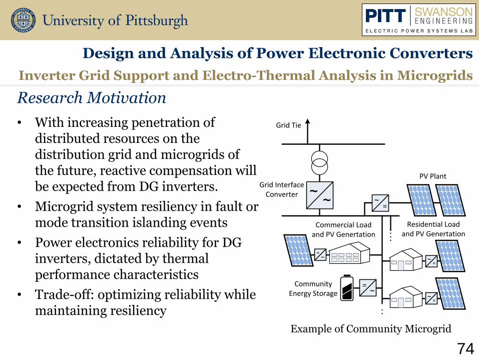
• With increasing penetration of distributed resources on the distribution grid and microgrids of the future, reactive compensation will be expected from DG inverters.
• Microgrid system resiliency in fault or mode transition islanding events
• Power electronics reliability for DG inverters, dictated by thermal performance characteristics
• Trade-off: optimizing reliability while maintaining resiliency
Design and Analysis of Power Electronic Converters
Grid Tie
PV PlantGrid Interface
Converter~=
Community Energy Storage ~
=
Commercial Load and PV Genertation
Residential Load and PV Genertation
~=
~=
~=
~~
Example of Community Microgrid
74

• During transition ride through event, injecting sufficient reactive current must be determined according to the measured voltage at the grid
𝑘 =(𝐼𝑞 − 𝐼𝑞0)/𝐼𝑟𝑎𝑡𝑒𝑑
(1 − 𝑣𝑔), 𝑤ℎ𝑒𝑟𝑒 𝐼𝑞 < 𝐼𝑟𝑎𝑡𝑒𝑑
Resiliency - Microgrid Inverter Modeling
Inverter Grid Support and Electro-Thermal Analysis in Microgrids
Design and Analysis of Power Electronic Converters
Source: Seal B., “Common Functions for Smart Inverters, Version 3” Electric Power Research Institute, Feb 2014
Source: Yongheng Yang; Huai Wang; Blaabjerg, F., "Reactive Power Injection Strategies for Single-Phase Photovoltaic Systems Considering Grid Requirements,“
in Industry Applications, IEEE Transactions on , vol.50, no.6, pp.4065-4076, Nov.-Dec. 2014 75

Inverter Grid Support and Electro-Thermal Analysis in Microgrids
Reliability - Device Performance
Design and Analysis of Power Electronic Converters
• Reliability of the power electronic converter depends primarily upon the thermal stress placed upon the devices
76 Voltages Vgs and Vds, and Current ID for both MOSFET turn on (top) and turn off (bottom) device operations
Switching Times tr Rise Time tf Fall Time

• Modeling of the switching energy and power losses of power MOSFETS utilizing a device characterization tool in ANSYS Simplorer
Reliability - Thermal Stress and Characterization
Inverter Grid Support and Electro-Thermal Analysis in Microgrids
Design and Analysis of Power Electronic Converters
77
3φ AC Grid Tie
Load
DC Source(PV emulator)
3φ DG Inverter
Transformer
MG Disconnect
Transient Thermal Impedance J-C

• Modeling of the switching energy and power losses of power MOSFETS utilizing a device characterization tool in ANSYS Simplorer
Reliability - Thermal Stress and Characterization
Inverter Grid Support and Electro-Thermal Analysis in Microgrids
Design and Analysis of Power Electronic Converters
78 Device Transfer Characteristics I-V
3φ AC Grid Tie
Load
DC Source(PV emulator)
3φ DG Inverter
Transformer
MG Disconnect