Embed Size (px)
Citation preview

1
Graphics in the game
Third Degree
By: Chad Williams
California Polytechnic State University
Advisor: Zoë Wood
Winter 2011 - Spring 2011

2
TABLE OF CONTENTS Introduction ................................................................................................................................................................... 4
Motivation ................................................................................................................................................................. 4
Team and Course Structure ....................................................................................................................................... 4
Project Overview ........................................................................................................................................................... 4
Story ........................................................................................................................................................................... 4
Genre & Setting ......................................................................................................................................................... 4
Game Mechanics ....................................................................................................................................................... 5
Look & Feel ................................................................................................................................................................ 5
Technical Specifics ..................................................................................................................................................... 5
Project Technologies ................................................................................................................................................. 5
Related Works ........................................................................................................................................................... 6
Graphics ......................................................................................................................................................................... 8
Shaders ...................................................................................................................................................................... 8
Deferred Rendering ............................................................................................................................................... 8
Glow Shader......................................................................................................................................................... 11
Normal Mapping Shader ...................................................................................................................................... 13
Respawn Effect Shader ........................................................................................................................................ 16
Performance Enhancements ................................................................................................................................... 18
Vertex Buffer Objects .......................................................................................................................................... 18
Texture and Mesh Instancing .............................................................................................................................. 19
Particle System Implementation ............................................................................................................................. 19
Overview .............................................................................................................................................................. 19

3
Configuration ....................................................................................................................................................... 20
Examples .............................................................................................................................................................. 21
Map Editor ................................................................................................................................................................... 22
Results ......................................................................................................................................................................... 23
Conclusion ................................................................................................................................................................... 24
Future Work ................................................................................................................................................................. 24
Credits .......................................................................................................................................................................... 25
List of Figures ............................................................................................................................................................... 25
References ................................................................................................................................................................... 25

4
INTRODUCTION
MOTIVATION Video games have been consistently driving hardware and graphics development, so having a senior project that
deals with the latest graphical technologies and techniques was a major motivation for the game. Another reason
to begin this project was to gain the experience working with a team on a large project. And finally, the main
reason for forming the team and beginning the project, of course, was to develop a game proof-of-concept. For my
senior project, with the assistance of the Third Degree team, I chose to develop a 3D sidescroller, focusing my
efforts on the graphical technologies involved in making a real-time game.
TEAM AND COURSE STRUCTURE Third Degree began work even before senior project started, with Mark Paddon, Mike Sanchez, and I fleshing out
the story as well as beginning tool and engine development. Once Spring quarter arrived, the team gained three
additional members (Jon Moorman, Tim Biggs, and Joshua Marcelo). Each team member had their own
specialization, such as in graphics or physics. Additional help from Ben and Tom Funderberg, as well as Josh
Holland, provided the game with art assets to enhance the visuals in the game, and Sam Thorn produced the
excellent sound featured in the game. Once the core team was established, official development took place
between Spring quarter 2011 and Winter quarter 2011 in the first-ever CPE 476++ course at Cal Poly, led by Zoë
Wood, focusing on 3D game development (3D engine architecture, graphical techniques and shaders, 3D spatial
optimizations, and more).
PROJECT OVERVIEW
STORY The game follows the story of a convict kept in confinement who is essentially given a chance at redemption
through a special testing program. A recent alien artifact has crash-landed on the Earth’s surface, and a group of
scientists are conducting specialized experiments to find out what it does. The convict is one in a line of test
subjects given a chance of freedom through experimentation. When the artifact is fitted on the convicts head, he is
put in some kind of virtual environment that resembles Victorian London in the 1860s. The convict, though
determined to gain his freedom, soon feels the grasp of insanity closing in around him (seen as the environment
changing to a futuristic setting, among other things), and the only way out is to either finish the virtual simulation,
or die trying.
GENRE & SETTING Third Degree is a 3D side-scrolling adventure game. The game takes place in the mind of the main character, and
the player is continually immersed with story-driven game play. Third Degree combines story elements, traditional
platforming, and interesting game mechanics to provide a unique player experience; meanwhile, the environment
is switching back and forth between Victorian and futuristic settings.

5
GAME MECHANICS The core game mechanic of Third Degree is the concept of “mental deterioration” (MD). The status of this
“deterioration” state is reflected in the Mental Deterioration Bar, or MD Bar for short. The MD of the player is
reflected in many ways in the game. The most apparent affect that MD has is on the game’s environment; initially
the environment will reflect the Victorian environment, and will slowly transition to a futuristic setting as the MD
increases. Additionally, the higher the MD, the more the distorted the environment will become, furthering the
concept of the player’s mental state. As the MD reaches nearly full (equivalent to “death”), the player must focus
in order to bring down their MD and restore the environment to a playable state. If at any point the player maxes
out their MD, they will respawn to the last checkpoint.
Aside from the MD, the player will be fighting against enemies in the twisted environment that the game is set in.
Enemies are strategically placed throughout the map, and the enemies’ attacks will increase the player’s MD for
each “hit” on the player. For defense, the player is equipped with a melee attack, as well as a simple gun. In
addition to the enemies impeding progress in the map, puzzle objects are placed throughout to make navigation
more difficult. Examples of puzzle objects include trapdoors, swinging platforms, and swinging blades. To pass
some of these puzzles, “Fire legs” must be employed. “Fire legs” is the game’s mechanic to allow the player to
jump higher than they normally would; the jump height increases with the player’s MD, giving the gamer an
incentive to balance their MD appropriately.
LOOK & FEEL As previously mentioned, there are two types of environments that the game takes place in, the Victorian setting
and the futuristic setting. The Victorian and futuristic settings were selected to heavily contrast each other and
provide distinct visual cues to the player. The Victorian environment contains many blocky, stone surfaces and is in
general very dreary, while the futuristic setting contains many metallic, curvy surfaces, with many of the objects
emitting a purple glow.
TECHNICAL SPECIFICS Microsoft’s Visual Studio 2008 was used as the main development platform for the team due to its excellent
debugging capabilities as well as its integration with Qt, which served as the UI framework for the game’s editor.
To facilitate team productivity, the SVN source-control system was used, as well as a ticketing and organization
solution found on Unfuddle.com. The core of the game was written in C++, with OpenGL serving as the graphics
API, and GLSL for the shaders in the game. The game’s engine was compiled to a DLL so it could be reused without
any code duplication in the main game itself as well as the game’s editor. On the art side of the project, the PNG
image format was chosen as the standard due to its lossless compression, and the WAV format for sound files.
Finally, the engine uses the SDL library for windowing, and the IrrKlang library for sound playback.
PROJECT TECHNOLOGIES Because Third Degree was developed in a team environment, each technology was typically developed by one or
two team members; refer to their project write-up for more information. The following list outlines the general
distribution of tasks within the project, but is not exhaustive:

6
Technology Authors/People involved
View Frustum Culling Josh
Skeletal Animations Josh
Enemy AI Josh
Player Control/Movement Josh, Tim
Combat System Josh, Tim, Mark
Editor - Object Transformations Josh
Editor - Main Functionality Chad
Deferred Rendering Chad, Ryan Schmitt
GLSL Shaders Chad
Core Engine Optimizations Chad
Particle System Implementation Chad
High Level Design Jon, Mark
Map Loading/Saving Jon
Physics Engine Integration Jon, Tim, Mark
Object/Joint System (aka Puzzle Objects) Jon, Tim
Glow Shader Jon, Chad
Animated Textures Michael, Mark
Menu System Michael
Fire Legs Implementation Michael, Tim
OBJ Importer Michael, Chad
Octree Mark
Sound Design Mark
Focus Mark
RELATED WORKS
While there were many influences for Third Degree, the following works both influenced the gameplay as well as
helped to provide examples for how to approach certain tasks for components in Third Degree.

7
Trine The general mood/feel of the game was greatly influenced by this side-scrolling platformer, Frozenbyte's Trine.
Visual inspirations, the overall feel of gameplay mechanics (such as movement and puzzle object interaction), and
elements of the combat system helped in making decisions for Third Degree. The Figure below shows an in-game
screenshot for Trine:
FIGURE 1 - FROZENBYTE'S TRINE
Maya
The transformation tools were modeled after many 3D graphics software suites, particularly Autodesk Maya. The
figure below shows an example of the transformation tools used in Maya:
FIGURE 2 - TRANSFORMATION TOOLS IN AUTODESK'S MAYA
8
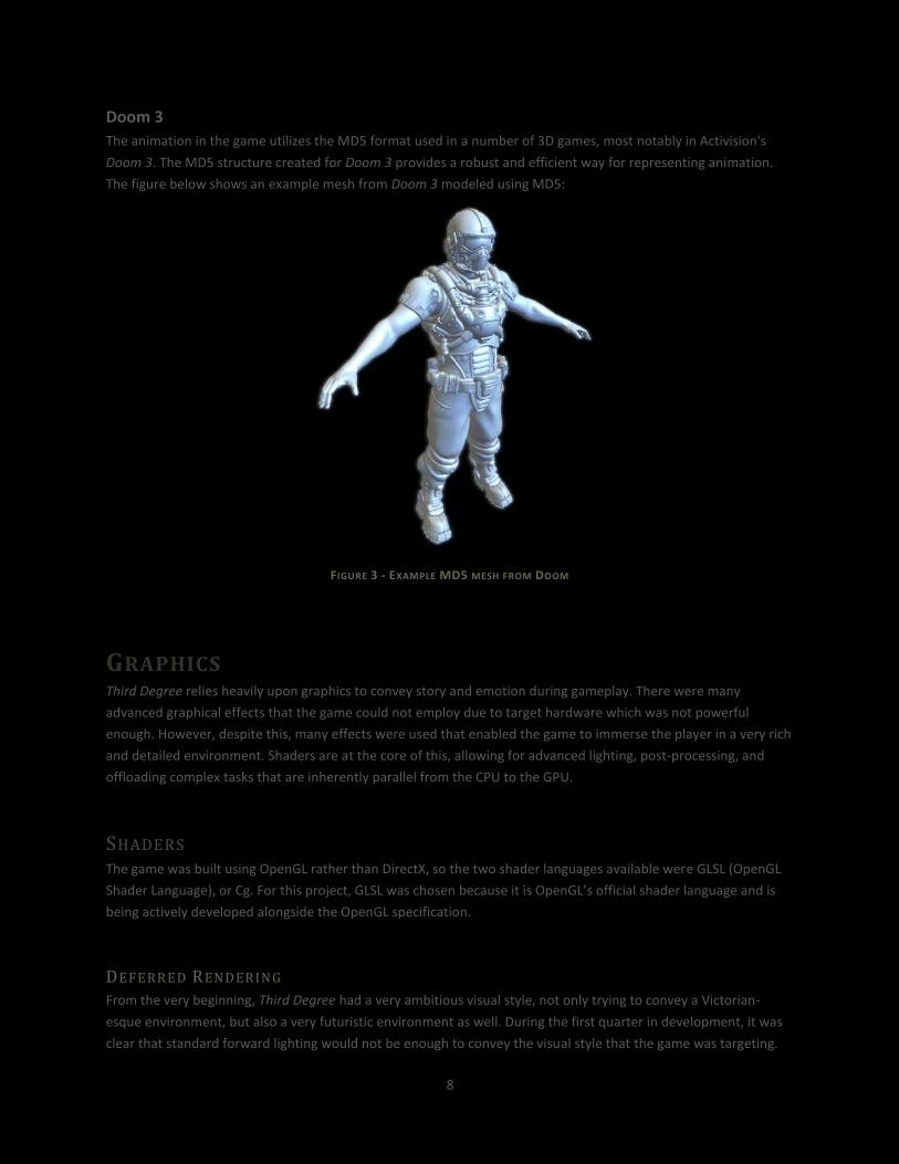
Doom 3
The animation in the game utilizes the MD5 format used in a number of 3D games, most notably in Activision's
Doom 3. The MD5 structure created for Doom 3 provides a robust and efficient way for representing animation.
The figure below shows an example mesh from Doom 3 modeled using MD5:
FIGURE 3 - EXAMPLE MD5 MESH FROM DOOM
GRAPHICS Third Degree relies heavily upon graphics to convey story and emotion during gameplay. There were many
advanced graphical effects that the game could not employ due to target hardware which was not powerful
enough. However, despite this, many effects were used that enabled the game to immerse the player in a very rich
and detailed environment. Shaders are at the core of this, allowing for advanced lighting, post-processing, and
offloading complex tasks that are inherently parallel from the CPU to the GPU.
SHADERS The game was built using OpenGL rather than DirectX, so the two shader languages available were GLSL (OpenGL
Shader Language), or Cg. For this project, GLSL was chosen because it is OpenGL’s official shader language and is
being actively developed alongside the OpenGL specification.
DEFERR ED REN DERIN G
From the very beginning, Third Degree had a very ambitious visual style, not only trying to convey a Victorian-
esque environment, but also a very futuristic environment as well. During the first quarter in development, it was
clear that standard forward lighting would not be enough to convey the visual style that the game was targeting.

9
Deferred rendering, which allows for lighting to be done in its own pass, allows for an essentially unlimited1number
of lights in the scene, allowing for a massive number of creative options to become available in the development
process. Third Degree owes credit of its core deferred rendering engine to Ryan Schmitt, who very graciously
allowed us to implement his deferred rendering code. Without the assistance Ryan provided, the advanced lighting
that Third Degree employs would certainly not have been attainable within the two-quarter time frame that the
game was developed in.
In order to focus the player’s attention on the objects that are switching between historical and futuristic
equivalents, the ambient light was set very low, and an abundance of point lights were used to highlight and
showcase the switchable objects. Below is an exploration of the way deferred rendering works (i.e., how Ryan’s
core system works, and how many other implementations function), and later in the report, how this core system
was modified to allow for advanced effects in Third Degree.
HO W DE F E R R E D RE N D E R I N G WO R K S
As the name implies, deferred rendering delays, or defers, the rendering/lighting of the scene until it is presented
to the screen. What this means, essentially, is that a shader is “gathering” (or capturing) all the data resulting from
OpenGL draw calls and placing this data in buffers. The three main buffers used in the core deferred rendering
system are an albedo buffer, a depth buffer, and a normal buffer.
Note that because the only color information stored in these three buffers is in the albedo buffer, no lighting
information is present (albedo is just color without any lighting information). Because of this, lighting can be
deferred until all three buffers are completely filled with the draw information for a complete frame. Collectively
these buffers are called a G-buffer, short for “geometry buffer.” With the information in these buffers, ambient,
directional, and point lighting (as well as other lighting models) can be calculated. Because the lighting is done
after the entire scene has been rendered to buffers, lighting is calculated per-pixel in view space. This has the
distinct advantage of only lighting pixels that are visible after the scene has been rendered. In the case of the
forward rendering model, having a large number of lights in the scene becomes very expensive, because for each
light in the scene, OpenGL has to compute the light for each object. Below is a summary of the complexity of
deferred and forward rendering models:
Forward rendering: O(M * L) …where M and L represent the number of meshes and lights present in the frame, respectively Deferred rendering: O(M + L)
The following three figures are a snapshot of the three core buffers that make deferred rendering possible:
1 “Essentially unlimited” means that almost any reasonable number of lights in the scene would have perfectly
decent performance.

10
FIGURE 4–DEFERRED RENDERING D EPTH BUFFER (NON-LINEARIZED)
FIGURE 5–DEFERRED RENDERING ALBEDO BUFFER

11
FIGURE 6–DEFERRED RENDERING NORMAL BUFFER (NON-NORMAL-MAPPED)
A clear disadvantage of deferred rendering is the large memory footprint required, since at least three buffers are
required to perform lighting (albedo, depth, and normals). If additional effects are desired, even more buffers will
be used, such as velocity, roughness, and specular buffers. Another disadvantage occurs when only a couple of
lights are in the scene – in this case deferred rendering is most likely more complex than forward lighting. In Third
Degree, however, each frame contains a large number of lights, so this disadvantage does not apply. Other
important disadvantages include difficulty rendering transparent objects in the scene (like glass), and anti-aliasing
problems. There are many techniques for anti-aliasing in the deferred rendering pipeline, but none of them rely on
traditional anti-aliasing provided by the hardware.
GLO W SHADER
In order to completely differentiate futuristic objects from historical objects, glow was applied to most future
objects. In order to support glow, a fourth MRT (multiple render target) was added to the deferred rendering
system. This fourth buffer contains color information which is then fed into the post-processing shader described
below. In a nutshell, objects that support glow have an associated glow mask (Figure 7), the gather shader then
masks off the albedo buffer with this glow mask, and places this masked albedo into the fourth MRT, which is the
glow buffer (Figure 8).

12
HO W T H E G L O W AL G O R I T H M WO R K S
The first step, as outlined above, is to write the albedo modulated by the glow mask into the glow buffer which will
subsequently be used in the glow shader. This step is done in the gather shader which is part of the deferred
rendering process:
gl_FragData[2] = texture2D(albedoTexture, Texcoord) * texture2D(glowTexture,
Texcoord);
The above code simply samples the glow mask (glowTexture) and albedo buffer (albedoTexture),
multiplies the samples together, and puts it into the fourth MRT. This works because the glow mask is either white
or black, so the glow buffer will be populated with the albedo color when the glow mask is white (represented in
color as RGBA = 1.0, 1.0, 1.0, 1.0) and black when the glow mask is black. Below are samples of an individual glow
mask (Figure 7), the glow MRT (Figure 8), and the final rendered image (Figure 9):
FIGURE 7 - GLOW MASK USED FOR THE FUTURE LAMP PROP
FIGURE 8 - GLOW MRT
FIGURE 9 - FINAL IMAGE WITH GLOW
13
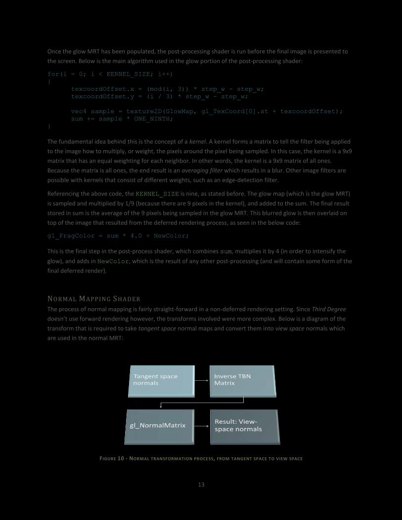
Once the glow MRT has been populated, the post-processing shader is run before the final image is presented to
the screen. Below is the main algorithm used in the glow portion of the post-processing shader:
for(i = 0; i < KERNEL_SIZE; i++)
{
texcoordOffset.x = (mod(i, 3)) * step_w - step_w;
texcoordOffset.y = (i / 3) * step_w - step_w;
vec4 sample = texture2D(GlowMap, gl_TexCoord[0].st + texcoordOffset);
sum += sample * ONE_NINTH;
}
The fundamental idea behind this is the concept of a kernel. A kernel forms a matrix to tell the filter being applied
to the image how to multiply, or weight, the pixels around the pixel being sampled. In this case, the kernel is a 9x9
matrix that has an equal weighting for each neighbor. In other words, the kernel is a 9x9 matrix of all ones.
Because the matrix is all ones, the end result is an averaging filter which results in a blur. Other image filters are
possible with kernels that consist of different weights, such as an edge-detection filter.
Referencing the above code, the KERNEL_SIZE is nine, as stated before. The glow map (which is the glow MRT)
is sampled and multiplied by 1/9 (because there are 9 pixels in the kernel), and added to the sum. The final result
stored in sum is the average of the 9 pixels being sampled in the glow MRT. This blurred glow is then overlaid on
top of the image that resulted from the deferred rendering process, as seen in the below code:
gl_FragColor = sum * 4.0 + NewColor;
This is the final step in the post-process shader, which combines sum, multiplies it by 4 (in order to intensify the
glow), and adds in NewColor, which is the result of any other post-processing (and will contain some form of the
final deferred render).
NOR MAL MAPPIN G SHADER
The process of normal mapping is fairly straight-forward in a non-deferred rendering setting. Since Third Degree
doesn’t use forward rendering however, the transforms involved were more complex. Below is a diagram of the
transform that is required to take tangent space normal maps and convert them into view space normals which
are used in the normal MRT:
FIGURE 10 - NORMAL TRANSFORMATION PROCESS, FROM TANGENT SPACE TO VIEW SPACE

14
The general process is to take the tangent-space normal from the normal map (assuming they are specified in
tangent space), multiply this normal by the inverse TBN matrix, and finally multiply it by the “normal matrix”
provided by OpenGL, which is a special 3x3 version of OpenGL’s 4x4 model-view matrix. This entire transformation
process is done on the GPU in GLSL because the GPU is particularly good at doing matrix multiplication. The only
components that are computed on the CPU are the tangents that are needed in order to generate the TBN
matrices. The tangent for the face in question is passed to the shader, and the inverse TBN matrix is constructed as
follows:
Normal = normalize(normal); // Passed from CPU
Tangent = normalize(tangent); // Passed from CPU
Bitangent = cross(Normal, Tangent);
Bitangent = normalize(Bitangent);
TBNmatrix = transpose(mat3x3(Tangent, Bitangent, Normal));
Referencing the above code, tangent is the tangent which has been passed into the shader, and normal is the
vertex normal which is NOT from the normal map. The bitangent is generated by taking the cross product of the
normal and tangent. The final TBN matrix is generated by composing a 3x3 matrix of the tangent, bitangent, and
normal, and taking the transpose of it in order to generate the inverse of the matrix. Because Third Degree
targeted GLSL version 1.2, and version 1.2 does not have a built-in function to take the inverse of a matrix, the
transpose was used instead because the transpose of an orthogonal matrix is the same as the inverse of a non-
orthogonal matrix.
The TBN matrix is then passed to the fragment shader, and used as follows:
finalNormal = normalize(texture2D(normalTexture, Texcoord).xyz * 2.0 - 1.0);
finalNormal = normalize(finalNormal * TBNmatrix);
vec3 packedNormal = (normalize(finalNormal) + 1.0) * 0.5;
gl_FragData[0] = vec4(packedNormal, 1.0);
First, the normal map is sampled and stored in finalNormal. Note that the normal originating from the normal
map is multiplied by 2 and then has 1 subtracted out. This process is done because the normals are stored in the
range [0, 1] inside the texture, and need to be transformed to the range [-1, 1] which is the appropriate range for
use in normal calculations. The normal from the normal map is then multiplied by the TBN matrix, stored back into
finalNormal, and “packed” back into the range of *0, 1+. Finally, the packed normal is stored in the MRT
containing normal information (gl_FragData[0]references the second MRT, which is the normal MRT – the
first MRT is depth, which is not accessible from gl_FragData). From this point, since the transformed normals are in
the normal MRT, the lighting calculations are carried out as normal by the deferred rendering system, and the
normal-mapping effect is complete.
15
FIGURE 11 - A TANGENT-SPACE NORMAL MAP USED ON THE CRATE PROP
FIGURE 12 - VIEW-SPACE NORMALS (CONTAINED IN THE NORMAL MRT)

16
FIGURE 13 - FINAL LIT IMAGE WITH NORMAL MAPPING
RESP AWN EFFECT SHADER
When the player in Third Degree dies (and respawns at the last checkpoint), or is spawned for the first time into
the world, an overwhelming “brightness” occurs which is called the “respawn effect.” The effect is composed of
two parts. The first part processes the final image to create a sepia effect; the second part of the effect involves
significantly brightening up the image.
OldColor = texture2D(DeferredScene, gl_TexCoord[0].st);
NewColor.r = OldColor.r * 0.393 + OldColor.g * 0.769 + OldColor.b * 0.189;
NewColor.g = OldColor.r * 0.349 + OldColor.g * 0.686 + OldColor.b * 0.168;
NewColor.b = OldColor.r * 0.272 + OldColor.g * 0.534 + OldColor.b * 0.131;
NewColor.a = 1.0;
Intensity = (20 - 19 * FadeLevel);
NewColor = Intensity * mix(NewColor, OldColor, FadeLevel);
The first step in the sepia effect is sampling the final image generated by the deferred rendering,
DeferredScene. The individual R, G, and B channels are then modulated by specific values to generate a sepia
effect (see Figure 14 below). The color generated by the sepia effect, stored in NewColor, is then modulated by
an intensity value to brighten up the image. The values selected in the intensity function are somewhat arbitrary
and were derived simply on a trial-and-error basis. FadeLevel is a value that varies from 0.0 to 1.0, so the end
result is that the image will be brightened by 20x when the FadeLevel is 0, and 1x (or no added brightness)
when the FadeLevel is 1. After the intensity is generated, NewColor and OldColor are simply linearly
interpolated via mix by the FadeLevel, and multiplied by the generated intensity.

17
FIGURE 14 - THE FIRST STAGE IN THE RESPAWN EFFECT (SEPIA)
FIGURE 15 - THE RESPAWN EFFECT MIDWAY THROUGH COMPLET ION. THE FINAL IMAGE IS GENERATED BY MULTIPLYING THE SEPIA FILTER
BY THE INTENSITY VALUE.
18
PERFORMANCE ENHANCEMENTS One of the most frequent problems encountered during the development of Third Degree was bad performance.
Most often Third Degree was CPU bound rather than GPU bound, relating to other non-graphical parts of the
game, but the area that I focused on was ensuring that the game never became severely GPU bound. The two
main areas that helped GPU performance the most were OpenGL’s Vertex Buffer Objects (VBOs), and
texture/mesh instancing.
VERT EX BUFFER OBJECTS
The core concept behind VBOs lies in a simple fact: sending a large portion of geometry data to the GPU at one
time is better than sending it in small chunks little by little. Immediate mode, most frequently used by beginners to
OpenGL, sends data to the GPU in very small pieces (one vertex, one color, etc at a time). On the opposite end of
the spectrum, VBOs send geometry data in chunks that are specified by the developer, meaning that an entire
model’s data could be sent to the GPU at once. Taking this concept even further, multiple models could be added
into a single VBO to speed up transferring data to the GPU even more. The main reason that VBOs are faster than
immediate mode drawing is simply because there are fewer calls to the graphics driver, resulting in less CPU usage.
The same goes for why putting multiple models inside a single VBO is faster than one model/entity per VBO: the
driver has to bind to VBOs less often and binding is an expensive operation (see NVIDIA’s Bindless Graphics2 to
speed this up even more).
Because Third Degree’s maps rely heavily on a wide variety of models (and many instances of these models) rather
than simple geometric primitives, VBOs had to work seamlessly into our engine’s architecture to ensure that they
were not a burden to use. The solution to this was to have every unique mesh that was created to automatically
create a VBO for that mesh, and each instance following would use the same VBO. The way this is done will be
described in Texture and Mesh Instancing.
VBOs are not only used in the meshes, but also in Third Degree’s particle system implementation. Due to the way
that the engine draws particles, each particle is a billboarded quad, meaning that four vertices per particle have to
be sent to the GPU. For large particle systems, this can equate to quite a large number of vertices. Drawing the
particles in immediate mode, as was done initially, resulted in a massive framerate slowdown. It turns out that
VBOs are also good for non-static geometry, and can just act as a vehicle for sending a large amount of data to the
GPU in one shot. VBOs are particularly good for static data since, assuming there is enough GPU memory, the static
data only needs to be sent once, but they will also result in a large speedup for dynamic data as well. VBOs can
have different “modes”, so for the static data the engine uses the GL_STATIC_DRAW mode, and for particles and
dynamic data that will change every frame, the engine uses GL_STREAM_DRAW.
The end result in using VBOs resulted in about a 50% improvement in framerate when used with particles, and
over a 300% framerate improvement when used with static meshes. The difference in improvement between
static meshes and particles is most likely due to the differences between GL_STATIC_DRAW and
GL_STREAM_DRAW, since static data is cached on the GPU, and the particles, which are streamed to the GPU, are
not cached. Clearly, VBOs should be used whenever they can due to the massive performance increases that
result. With this said, Third Degree’s engine still uses immediate mode in some cases, like for drawing debug
information, due to the ease of drawing lines and other temporary primitives in immediate mode.
2 NVIDIA’s Bindless Graphics: http://developer.nvidia.com/content/bindless-graphics

19
TEXT UR E AN D MES H IN ST AN CIN G
Due to the detailed and rich environment that Third Degree aims to immerse the player in, efficient management
of textures and meshes is critical. In the tutorial map, approximately 50 textures, and up to 100 different meshes
(due to the fact that both historical and futuristic models are present) are loaded in.
Initially, the engine took a “dumb” approach to loading in assets, and treated each individual instance of a model
or texture as a unique entity, loading it in even if that particular entity had been loaded already. This worked fine
when the maps were small, but as the maps increased in size, it was clear that a more intelligent approach to asset
management had to be taken.
First, texture management was worked into the engine’s texture class. With the new texture management feature
implemented, the only way to create a texture in the engine is to go through the texture class. The
“RequestNewTexture” method is the way of accessing texture information, and will return a pointer to the
requested texture if it has already been loaded, or load the texture in and return a pointer to the texture if it has
not been loaded in yet. With texture instancing, Third Degree normally uses approximately 550MB of non-GPU
memory. However, without texture instancing, about 750MB of memory is used – 200MB of duplicated textures!
Although unrelated to instancing, the texture class further optimized the usage of textures by looking at the
currently bound texture (which is cached – OpenGL is not queried) and only binding to the requested texture if it is
not currently bound. This feature, although very simple, resulted in a large speedup. Again, the reason for this is
that binding to resources within OpenGL is a very expensive operation, and the less it is done, the faster the
graphical application will be.
The mesh class followed the same management idea that the texture class employed, creating a similar
“RequestNewMesh” method, which would only load in a mesh if it had not been loaded in already. The mesh
class uses VBOs to draw, so the overhead of using VBOs is completely hidden from users of the class.
PARTICLE SYSTEM IMPLEMENTATION To add further visual effect to Third Degree, the particle system from my CPE 471 final project was integrated and
enhanced to work in a cohesive way in the game. The particular enhancements to the system will not be discussed
in this section, but rather an overview of how the system works as a whole, and the various ways the particle
system can be configured.
OV ERVI EW
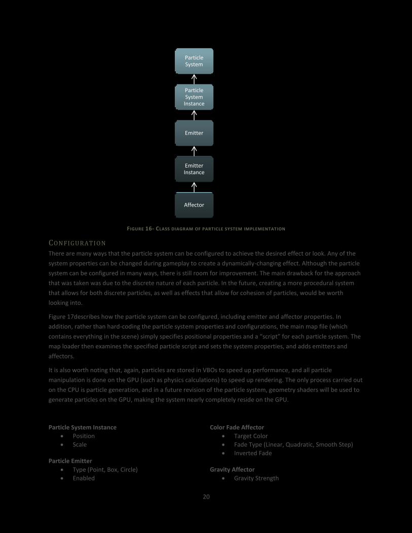
Figure 16 illustrates the basic class organization of the particle system implementation. Each particle system can
have any number of emitters, and each emitter can have any number of “affectors,” which are entities that
manipulate, or affect, the emitter in some way (such as color or position). Furthermore, emitters and system
containers can be instanced in order to avoid duplicating properties that are common to the system as a whole or
the emitter – this allows for a large number of the same particle effect to be placed efficiently throughout the
scene.
20
FIGURE 16- CLASS DIAGRAM OF PARTICLE SYSTEM IMPLEMENTATION
CON FIGURATI O N
There are many ways that the particle system can be configured to achieve the desired effect or look. Any of the
system properties can be changed during gameplay to create a dynamically-changing effect. Although the particle
system can be configured in many ways, there is still room for improvement. The main drawback for the approach
that was taken was due to the discrete nature of each particle. In the future, creating a more procedural system
that allows for both discrete particles, as well as effects that allow for cohesion of particles, would be worth
looking into.
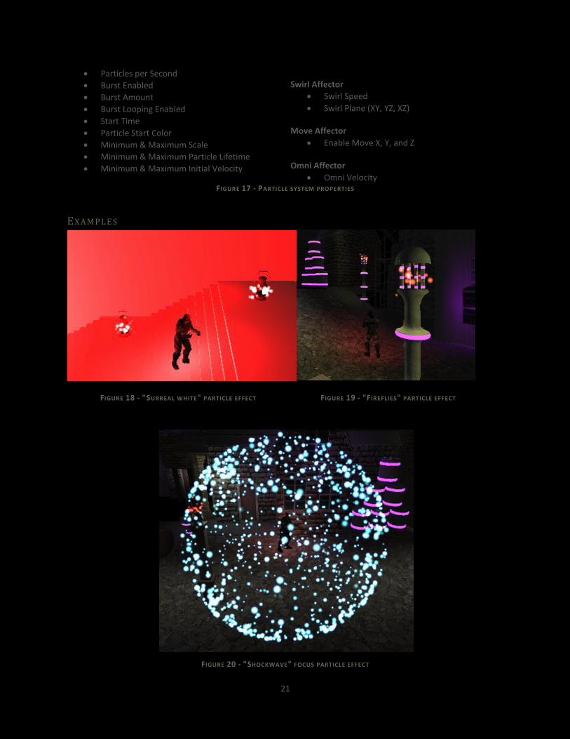
Figure 17describes how the particle system can be configured, including emitter and affector properties. In
addition, rather than hard-coding the particle system properties and configurations, the main map file (which
contains everything in the scene) simply specifies positional properties and a “script” for each particle system. The
map loader then examines the specified particle script and sets the system properties, and adds emitters and
affectors.
It is also worth noting that, again, particles are stored in VBOs to speed up performance, and all particle
manipulation is done on the GPU (such as physics calculations) to speed up rendering. The only process carried out
on the CPU is particle generation, and in a future revision of the particle system, geometry shaders will be used to
generate particles on the GPU, making the system nearly completely reside on the GPU.
Particle System Instance
Position
Scale Particle Emitter
Type (Point, Box, Circle)
Enabled
Color Fade Affector
Target Color
Fade Type (Linear, Quadratic, Smooth Step)
Inverted Fade Gravity Affector
Gravity Strength
Particle System
Particle System
Instance
Emitter
Emitter Instance
Affector
21
Particles per Second
Burst Enabled
Burst Amount
Burst Looping Enabled
Start Time
Particle Start Color
Minimum & Maximum Scale
Minimum & Maximum Particle Lifetime
Minimum & Maximum Initial Velocity
Swirl Affector
Swirl Speed
Swirl Plane (XY, YZ, XZ) Move Affector
Enable Move X, Y, and Z Omni Affector
Omni Velocity FIGURE 17 - PARTICLE SYSTEM PROPERTIES
EXAMP LES
FIGURE 18 - "SURREAL WHITE" PARTICLE EFFECT FIGURE 19 - "FIREFLIES" PARTICLE EFFECT
FIGURE 20 - "SHOCKWAVE" FOCUS PARTICLE EFFECT
22
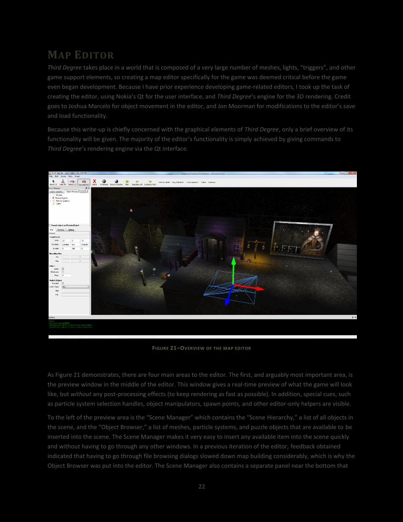
MAP EDITOR Third Degree takes place in a world that is composed of a very large number of meshes, lights, “triggers”, and other
game support elements, so creating a map editor specifically for the game was deemed critical before the game
even began development. Because I have prior experience developing game-related editors, I took up the task of
creating the editor, using Nokia’s Qt for the user interface, and Third Degree’s engine for the 3D rendering. Credit
goes to Joshua Marcelo for object movement in the editor, and Jon Moorman for modifications to the editor’s save
and load functionality.
Because this write-up is chiefly concerned with the graphical elements of Third Degree, only a brief overview of its
functionality will be given. The majority of the editor’s functionality is simply achieved by giving commands to
Third Degree’s rendering engine via the Qt interface.
FIGURE 21–OVERVIEW OF THE MAP EDITOR
As Figure 21 demonstrates, there are four main areas to the editor. The first, and arguably most important area, is
the preview window in the middle of the editor. This window gives a real-time preview of what the game will look
like, but without any post-processing effects (to keep rendering as fast as possible). In addition, special cues, such
as particle system selection handles, object manipulators, spawn points, and other editor-only helpers are visible.
To the left of the preview area is the “Scene Manager” which contains the “Scene Hierarchy,” a list of all objects in
the scene, and the “Object Browser,” a list of meshes, particle systems, and puzzle objects that are available to be
inserted into the scene. The Scene Manager makes it very easy to insert any available item into the scene quickly
and without having to go through any other windows. In a previous iteration of the editor, feedback obtained
indicated that having to go through file browsing dialogs slowed down map building considerably, which is why the
Object Browser was put into the editor. The Scene Manager also contains a separate panel near the bottom that

23
allows the user to specify translation, scale, and rotation per-object, object-switching properties, light properties,
and more.
At the bottom of the editor, the console gives information back to the user regarding actions that have been
completed, errors that occurred, and any warnings that may indicate a potential problem has arisen. The console
was not in the first iteration of the editor, and has proven invaluable in debugging and giving feedback to the
artists as to what is happening in the scene.
Lastly, the toolbar (at the top of the editor) provides quick access to actions that the artist may frequently utilize,
such as toggling the map between 100% future and 100% historical preview, manipulating the ambient light
settings for easy editing, duplicating an object to the left or right (good for tiling road objects), etc. The menu bar
(not to be confused with the toolbar that has large buttons) exposes all the actions available in the editor (showing
available hotkeys), including full undo/redo.
RESULTS The end result of Third Degree’s two-quarter development cycle was a solid proof-of-concept that many team
members plan on taking further and possibly selling on Steam. The original premise of the game was extremely
ambitious, and Third Degree accomplished a lot, including excellent graphics, gameplay prototyping, a strong
backend engine (including support for physics), a developed story, and a robust editor. A screenshot from the final
game is shown below:
FIGURE 22 - THE FINISHED GAME PROTOTYPE
24
During testing there was lots of feedback given to help improve the game and determine what was working and
what was not. One of the aspects that people liked in the game was the graphically rich environment, with
emphasis on the lighting. People also liked the physics effects (which were done with NVIDIA’s PhysX), and the
simple fact that the game was a side-scroller. Some aspects that people did not like included not being able to see
the bullets well, the overly-dynamic nature of the camera, inconsistent frame rates in certain areas of the map,
and the gun of the player being too small. Much of the feedback was incorporated into the final version of the
game, but there is still a lot that the team did not have time incorporate.
In hindsight, the entire team realized that the original game’s concept was too large for the two-quarter class, and
future teams should have such an ambitious scope. The primary reason that many of Third Degree’s planned
features did not get incorporated was due to the simple fact that the game is a story-based game. This one fact
created many problems for our development cycle, including needing the creation of many complex 3D assets in a
largely programmer team, a developed story, voiceovers, cut scenes, and more. All of this wound up being too
much to accomplish within a two-quarter time frame. Much of the outside help we had recruited for help in
developing these non-programming aspects of the game dropped due to time constraints or other problems. In
addition, because Third Degree takes place in a complex environment, the need for an editor arose. The
development time for the editor took away a lot of the time that could have been used on gameplay, but there
was no way to get away from the need for an editor for this specific game.
CONCLUSION As someone wanting to break into the graphics field, game-related or not, developing this game has been an
invaluable experience. Some of the topics that I have greatly expanded my knowledge in include GLSL shaders and
the role hardware plays in these, graphics performance bottlenecks, general C++ knowledge, game engine
architecture, and buffer-based graphical techniques.
However, despite the vast amount of graphical knowledge acquired while working on Third Degree, I also learned
even more about team dynamics. Before this project, I had never worked on a team this large trying to develop a
program this complex. On the outside, games don’t appear amazingly complex, but when you have to develop
them, you learn how incredibly intricate they really are. Coming into the project as Technical Manager, I was
tasked with getting everyone on the team focusing in a certain area and assigning them initial tasks. With everyone
on their own schedule and armed with limited game-development experience, this proved to be more difficult
than I expected. Throughout the period of the two-quarter development cycle, I learned a great deal on how to
keep people on task and continuing work, and when to take a member off a task.
FUTURE WORK During the summer the team plans on continuing further development on Third Degree – the ultimate goal is to
publish the game on Steam as an indie game. Senior project served as a platform to develop a stable proof-of-
concept game that could possibly be developed further. The team agrees that it would indeed be worth continuing
development on, so the next steps in development include improving gameplay mechanics and creating additional
maps that the story will progress through. Because my specialty is graphics, I will more than likely continue
furthering the look of Third Degree, such as enhancing the deferred rendering engine to include specular
calculations, and improving the appearance of other mechanics in the game like “Fire Legs.”

25
CREDITS Third Degree relied on a large amount of outside help to accomplish its ambitious goals. The following people
contributed their time to the project in the specified areas:
Josh Holland Art lead, 2D artwork Ben Funderberg 3D modeling Tom Funderberg 3D modeling Hector Zhu Splash screen, game modes Mikkel Sandberg 3D modeling Mitch Epeneter Voice acting Ryan Schmitt Core deferred rendering system
LIST OF FIGURES Figure 1 - Frozenbyte's Trine ......................................................................................................................................... 7
Figure 2 - Transformation tools in Autodesk's Maya ..................................................................................................... 7
Figure 3 - Example MD5 mesh from Doom ................................................................................................................... 8
Figure 4 – Deferred rendering depth buffer (non-linearized) ..................................................................................... 10
Figure 5 – Deferred rendering albedo buffer .............................................................................................................. 10
Figure 6 – Deferred rendering normal buffer (non-normal-mapped) ......................................................................... 11
Figure 7 - Glow mask used for the future lamp prop .................................................................................................. 12
Figure 8 - Glow MRT .................................................................................................................................................... 12
Figure 9 - Final image with glow .................................................................................................................................. 12
Figure 10 - Normal transformation process, from tangent space to view space ........................................................ 13
Figure 11 - A tangent-space normal map used on the crate prop ............................................................................... 15
Figure 12 - View-space normals (contained in the normal MRT) ................................................................................ 15
Figure 13 - Final lit image with normal mapping ......................................................................................................... 16
Figure 14 - The first stage in the respawn effect (sepia) ............................................................................................. 17
Figure 15 - The respawn effect midway through completion. The final image is generated by multiplying the sepia
filter by the intensity value. ......................................................................................................................................... 17
Figure 16- Class diagram of particle system implementation ..................................................................................... 20
Figure 17 - Particle system properties ......................................................................................................................... 21
Figure 18 - "Surreal white" particle effect ................................................................................................................... 21
Figure 19 - "Fireflies" particle effect ............................................................................................................................ 21
Figure 20 - "Shockwave" focus particle effect ............................................................................................................. 21
Figure 21 – Overview of the map editor ...................................................................................................................... 22
Figure 22 - The finished game prototype .................................................................................................................... 23
REFERENCES Guinot, J. (2006, December 30). Bump Mapping using GLSL. Retrieved from oZone3D:
http://www.ozone3d.net/tutorials/bump_mapping.php
Guinot, J., & Riccio, C. (2007, January 7). OpenGL Vertex Buffer Objects. Retrieved from oZone3D:
http://www.ozone3d.net/tutorials/opengl_vbo.php

26
O. A. (n.d.). OpenGL 2.1 Reference Pages. Retrieved from http://www.opengl.org/sdk/docs/man/
O'Rorke, J., & James, G. (2004, May 26). Real-Time Glow. Retrieved from Gamasutra:
http://www.gamasutra.com/view/feature/2107/realtime_glow.php
Paul. (n.d.). Simple Bumpmapping. Retrieved from Paul's Projects:
http://www.paulsprojects.net/tutorials/simplebump/simplebump.html
Poag, J. (2009, August 12). Black & White (sepia filter) GLSL. Retrieved from Irrlicht Forums:
http://irrlicht.sourceforge.net/phpBB2/viewtopic.php?p=202176
Ringle, E. (2010, September 7). Ditching Immediate Mode: OpenGL Vertex Buffer Objects. Retrieved from
http://eddieringle.com/ditching-immediate-mode-opengl-vertex-buffer-objects/
Rost, R. J., & Licea-Kane, B. (2009). OpenGL Shading Language, 3rd Edition. Addison-Wesley Professional.
Valient, M. (2007, July). Deferred Rendering in Killzone 2. Retrieved from http://www.guerrilla-
games.com/publications/dr_kz2_rsx_dev07.pdf