Embed Size (px)
Citation preview
NASA TECHNICAL NOTE
!
Zl--
Z
NASA TN D-6714
GRAPHITE FLUORIDE
AS A SOLID LUBRICANT
IN A POLYIMIDE BINDER
by Robert L. Fusaro and Harold E. SHney
Lewis Research Center
Cleveland, Ohio 44135
NATIONAL AERONAUTICS AND SPACE ADMINISTRATION • WASHINGTON, D. C. • MARCH 1972
https://ntrs.nasa.gov/search.jsp?R=19720010846 2018-06-11T17:33:34+00:00Z
1. Report No.' ' 2. Government Accession No. 3.
NASA TN D-6714
4. Title and Subtitle 5.
GRAPHITE FLUORIDE AS A SOLID LUBRICANT IN A
POLYIMIDE BINDER 6.
7. Author(s) 8.
Robert L. Fusaro and Harold E. Sliney
10.
9. Performing Organization Name and Address
Lewis Research Center 11.
National Aeronautics and Space Administration
Cleveland, Ohio 44135 13.
12. Sponsoring Agency Name and Address
National Aeronautics and Space Administration14.
Washington, D.C. 20546
Recipient's Catalog No.
Report Date
March 1972
Performing Organization Code
Performing Organization Report No.
E-6694
Work Unit No.
132-15
Contract or Grant No.
Type of Report and Period Covered
Technical Note
Sponsoring Agency Code
15. Supplementary Notes
16. Abstract
Polyimide resin (PI) was shown to be a suitable binder material for the solid lubricant graphite
fluoride ((CF1.1)n). Comparisons were made to similar tests using PI-bonded MoS 2 films,
(CF 1 1) n rubbed films, and MoS 2 rubbed films. The results showed that, at any one specific
temperature between 25 ° and 400 ° C, the wear life of PI-bonded (CF1.1)n films exceeded those
of the other three films by at least a factor of 2 and by as much as a factor of 60. Minimum
friction coefficients for the PI-bonded films were 0.08 for (CF1. 1)n and 0.04 for MoS 2. The
rider wear rates for the two PI-bonded films at 25 ° C were nearly equal.
17. Key Words (Suggested by Author{s))
Solid lubricant High-temperature lubrication
Graphite fluoride Bonded coating
Polyimide
18. Distribution Statement
Unclassified - unlimited
19. Security Classif. (of this report)
Unclassified
20. Security Classif. (of this page)
Unclassified
21. No. of Pages
17
22. Price*
$3.00
* For sale by the National Technical Information Service, Springfield, Virginia 22151

I
GRAPHITEFLUORIDEAS A SOLIDLUBRICANTIN A POLYIMIDEBINDER
by Robert t Fusaro and Harold E Sliney
Lewis Research Center
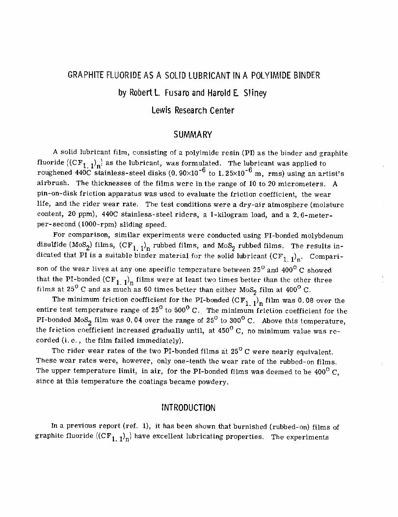
SUMMARY
A solid lubricant film, consisting of a polyimide resin (PI) as the binder and graphite
fluoride ((CF1.1)n) as the lubricant, was formulated. The lubricant was applied to
roughened 440C stainless-steel disks (0.90×10 -6 to 1.25x10 -6 m, rms) using an artist's
airbrush. The thicknesses of the films were in the range of 10 to 20 micrometers. A
pin-on-disk friction apparatus was used to evaluate the friction coefficient, the wear
life, and the rider wear rate. The test conditions were a dry-air atmosphere (moisture
content, 20 ppm), 440C stainless-steel riders, a 1-kilogram load, and a 2.6-meter-
per-second (1000-rpm) sliding speed.
For comparison, similar experiments were conducted using PI-bonded molybdenum
disulfide (MoS2) films, (CF1.1) n rubbed films, and MoS 2 rubbed films. The results in-
dicated that PI is a suitable binder material for the solid lubricant (CF1.1) n. Compari-
son of the wear lives at any one specific temperature between 25 ° and 400 ° C showed
that the PI-bonded (CF1. 1) n films were at least two times better than the other three
films at 25 ° C and as much as 60 times better than either MoS 2 film at 400 ° C.
The minimum friction coefficient for the PI-bonded (CF1.1) n film was 0.08 over theentire test temperature range of 25 ° to 500 ° C. The minimum friction coefficient for the
PI-bonded MoS 2 film was 0.04 over the range of 25 ° to 300 ° C. Above this temperature,
the friction coefficient increased gradually until, at 450 ° C, no minimum value was re-
corded (i. e., the film failed immediately).
The rider wear rates of the two PI-bonded films at 25 ° C were nearly equivalent.
These wear rates were, however, only one-tenth the wear rate of the rubbed-on films.
The upper temperature limit, in air, for the PI-bonded films was deemed to be 400 ° C,
since at this temperature the coatings became powdery.
INTRODUCTION
In a previous report (ref. 1), it has been shown that burnished (rubbed-on) films of
graphite fluoride ((CF1.1)n) have excellent lubricating properties. The experiments
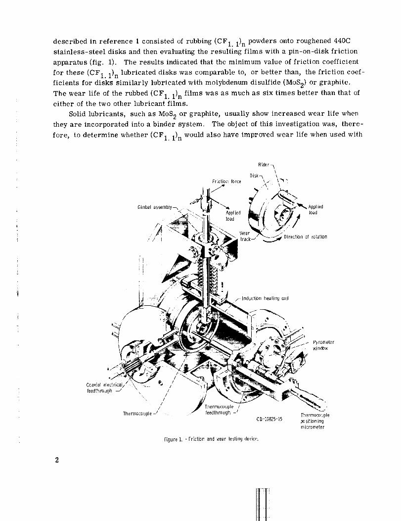
described in reference 1 consisted of rubbing (CF1. 1)npowders onto roughened440Cstainless-steel disks and then evaluating the resulting films with a pin-on-disk frictionapparatus (fig. 1). The results indicated that the minimum value of friction coefficient
for these (CF1.1)n lubricated disks was comparable to, or better than, the friction coef-ficients for disks similarly lubricated with molybdenumdisulfide (MoS2)or graphite.The wear life of the rubbed (CF1.1)n films was as much as six times better than that ofeither of the two other lubricant films.
Solid lubricants, suchas MoS2 or graphite, usually show increased wear life when
they are incorporated into a binder system. The object of this investigation was, there-
fore, to determine whether (CF1.1)n would also have improved wear life when used with
I|
t/--Induction heating coil
/
Coaxial electrical// _ _ /
feedth rough -/ //
//
/
Thermocouple J
Thermocouple /
! feedthrough _f
CD-10825-15
Figure 1. - Friction and wear testing device.
Thermocouple
positioningmicrometer
a binder material. A secondary objective was to compare the results to those obtained
when MoS 2 was used with the same binder material.
The binder material used in these experiments was a polyimide resin (manufac-
turer's designation, PI-4701) (ref. 2). Polyimide has been shown in previous Lewis Re-
search Center reports (refs. 3 to 6) to be a good friction and wear material. Also refer-
ence 7 has reported good results using it as a binder material for MoS 2. In addition,
(CF1.1)n was found to mix readily with the polyimide varnish. For these reasons and
because it was stable in air to over 400 ° C, it was chosen as the binder material.
The experimental conditions used in these tests were a 2.6-meter-per-second
(1000-rpm) sliding speed, a 1-kilogram load, a dry-air atmosphere (moisture content,
20 ppm), and 440C stainless-steel riders and disks.
MATERIALS
Graph ite Fluoride
A brief review of the history and physical properties of graphite fluoride ((CF1.1)n)
is given in reference 1. Mter the publication of that work, the existence of a patent en-
titled "Dry Lubrication _' (ref. 8) was discovered. The patent was granted on July 25,
1961; it describes a product with a carbon-to-fluorine ratio of 1: 1. The patent states,
"Fluorinated graphite has outstanding dry lubricating properties. '_ However, no data
supporting this statement were included with the patent and quantitative information was
not available prior to reference 1.
More recently, Ishikawa and Shimada (ref. 9) have used graphite fluoride as an addi-
tive in grease, mechanical carbons, and polytetrafluoroethylene (PTFE) - fibrous car-
bon composites. In each instance, beneficial results were reported. They found in-
creased load-carrying capacity, reduced surface temperatures, or seizure prevention.
Gisser, Petronio, and Shapiro (ref. 10) have also conducted some exploratory tests
on the friction and wear properties of graphite fluoride. They found that, by adding
2-percent graphite fluoride to a lithium soap - diester grease, low friction could be at-
tained at temperatures up to 344 ° C. The grease alone or with graphite added failed at
215 ° C. They also tested graphite fluoride in a silicate binder and in an epoxy-phenolic
binder. In general, they found that films formulated with graphite fluoride gave better
friction and wear results than similar films formulated with graphite.
Polyimides
Most polymers lose their rigidity and strength at elevated temperatures (refs. 11
3
and 12). One of the reasons for this is that their chain-like structure is weakenedby theincreased molecular vibrations associatedwith increased temperatures. There are twopossible consequencesof thesevibrations: Either the bondsbetweenthe monomer unitsbreak and the polymer disintegrates, or the polymer melts.
To obtain polymers with improved thermal stability, it is necessary to devise ameans of stiffening the molecules so that heat and its resulting vibrations will have lesseffect (ref. 12). A methodof accomplishing this is by the insertion of aromatic rings(rings of carbon atoms) into the polymer chains (refs. 13 to 15). These resulting poly-mers are designatedaromatic polymers. Polymers of this type havean upper tempera-ture limit of about 300° C (refs. 12and 15).
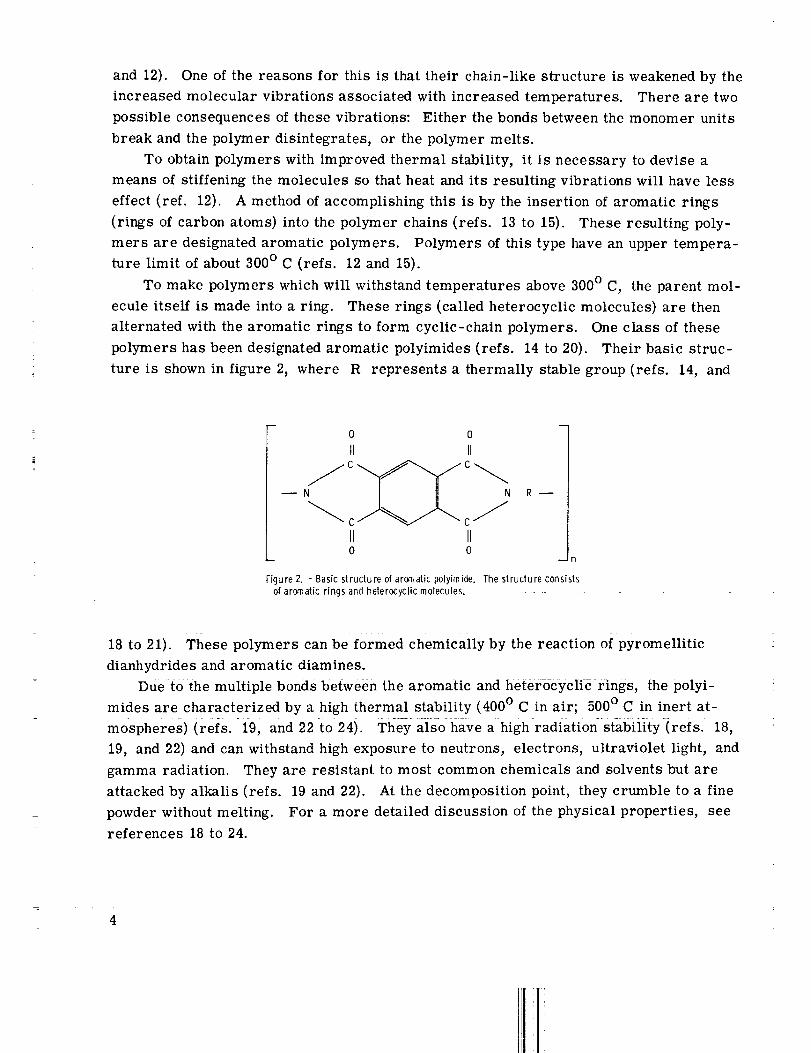
To make polymers which will withstand temperatures above300° C, the parent mol-ecule itself is madeinto a ring. These rings (called heterocyclic molecules) are thenalternated with the aromatic rings to form cyclic-chain polymers. Oneclass of thesepolymers hasbeendesignatedaromatic polyimides (refs. 14to 20). Their basic struc-ture is shownin figure 2, where R represents a thermally stable group (refs. 14, and
0 0
I1 II
--N N R --
II II0 0
Figure 2. - Basic structure of aromatic polyimi_e. The structure consistsof aromatic rings and heterocyc!ic molecules.
18 to 21). These polymers can be formed chemically by the reaction of pyromellitic
dianhydrides and aromatic diamines.
Due to the multiple bonds between the aromatic and heter6cyciic rings, the poiyi-
mides are characterized by a high thermal stability (400 ° C in air; 500 ° C in inert at-
mospheres) (refs....... 19, and 22-to 24). They also have a high-radiations_l_iiity-irefs. 18,
19, and 22) and can withstand high exposure to neutrons, electrons, ultraviolet light, and
gamma radiation. They are resistant to most common chemicals and solvents but are
attacked by alkalis (refs. 19 and 22). At the decomposition point, they crumble to a fine
powder without melting. For a more detailed discussion of the physical properties, see
references 18 to 24.
4
APPARATUS DESC RIPTION
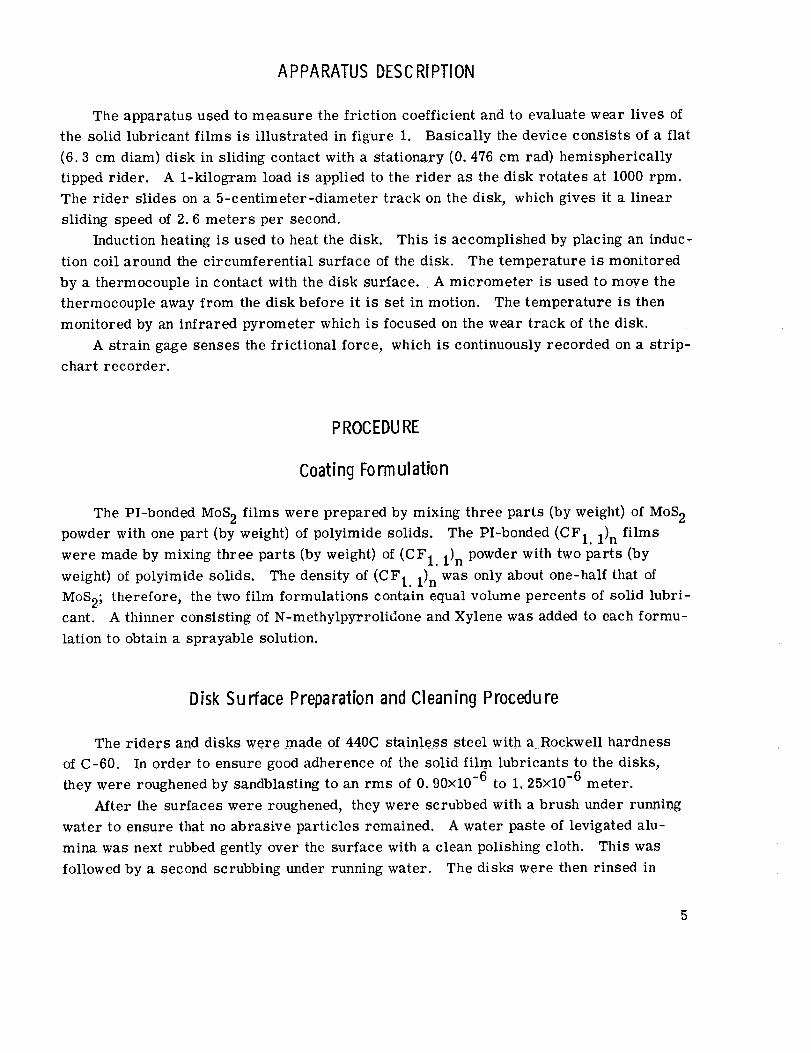
The apparatus used to measure the friction coefficient and to evaluate wear lives of
the solid lubricant films is illustrated in figure 1. Basically the device consists of a flat
(6.3 cm diam) disk in sliding contact with a stationary (0. 476 cm rad) hemispherically
tipped rider. A 1-kilogram load is applied to the rider as the disk rotates at 1000 rpm.
The rider slides on a 5-centimeter-diameter track on the disk, which gives it a linear
sliding speed of 2.6 meters per second.
Induction heating is used to heat the disk. This is accomplished by placing an induc-
tion coil around the circumferential surface of the disk. The temperature is monitored
by a thermocouple in contact with the disk surface. A micrometer is used to move the
thermocouple away from the disk before it is set in motion. The temperature is then
monitored by an infrared pyrometer which is focused on the wear track of the disk.
A strain gage senses the frictional force, which is continuously recorded on a strip-
chart recorder.
PROCEDU RE
Coating Form ulation
The PI-bonded MoS 2 films were prepared by mixing three parts (by weight) of MoS 2
powder with one part (by weight) of polyimide solids. The PI-bonded (CF1. 1)n films
were made by mixing three parts (by weight) of (CF1.1)n powder with two parts (by
weight) of polyimide solids. The density of (CF1.1)n was only about one-half that of
MoS2; therefore, the two film formulations contain equal volume percents of solid lubri-
cant. A thinner consisting of N-methylpyrrolidone and Xylene was added to each formu-
lation to obtain a sprayable solution.
Disk Su rface Preparation and Cleaning Proceclu re
The riders and disks were made of 440C stainless steel with a Rockwell hardness
of C-60. In order to ensure good adherence of the solid film lubricants to the disks,
they were roughened by sandblasting to an rms of 0.90x10 -6 to 1.25x10 -6 meter.
After the surfaces were roughened, they were scrubbed with a brush under running
water to ensure that no abrasive particles remained. A water paste of levigated alu-
mina was next rubbed gently over the surface with a clean polishing cloth. This was
followed by a second scrubbing under running water. The disks were then rinsed in
distilled water and stored in a desiccator until they were coatedwith the solid lubricant.The riders were first scrubbedwith alcohol. Then a water paste of levigated alu-
mina was applied with a polishing cloth. Cleaningcontinueduntil no trace of sedimentfrom the rider appearedon the cloth. The riders were then rinsed in distilled waterand stored in the desiccator until used.
Application of Lubricant Films
Some tests were conducted using disks burnished with MoS 2 or (CF1.1)n powders.
These coatings were applied by rubbing the powder onto the disk surface with the back
of a napped polishing cloth. The polishing cloth was made of open weave fabric (twilled)
and thus served as a good applicator.
The liquid mixture of polyimide and solid lubricant was sprayed onto each disk
using an artist's airbrush. The coating did not dry rapidly. Thus, if more than a thin
coat was applied, the liquid "ran" and a nonuniform coating resulted. To eliminate
this "running" and to obtain the desired coating thickness, it was necessary to spray
a thin coating of the formulation onto the disk, bake it at 100 ° C in an oven for 1 hour,
and then spray another thin coating on the disk and repeat the procedure.
When the desired thickness of 10 to 20 micrometers was obtained, the remainder
of the curing procedure was carried out. This procedure was to bake the coating at
100 ° C for 1 hour and then to bake it for an additional hour at 300 ° C. After the disks
had cooled, some additional solid lubricant powder was rubbed onto the polyimide -
solid lubricant film. This procedure was the same as that used for the burnished films.
Test Procedure
The procedure for conducting the wear life tests was as follows: a rider and a
disk (with the applied solid lubricant film) were inserted into the friction apparatus
(fig. 1). The test chamber was sealed, and dry air (moisture content, 20 ppm) was
purged through the chamber for 15 minutes. The flow rate was 1500 cubic centimeters
per minute. This flow rate maintained a slight positive pressure in the chamber, which
had a volume of 2000 cubic centimeters.
When the purge was completed, the temperature of the disk was slowly raised to
the desired temperature by using induction heating. The temperature was held for
10 minutes to allow it to stabilize. The disk was then set into rotation at 1000 rpm,
and a 1-kilogram load was applied.
The criterion for failure in these tests was a friction coefficient of 0.30. An auto-
6
matic cutoff system shut downthe apparatuswhenthe friction coefficient reached thisvalue.
In order to calculate the rider wear rate at 25° C, the tests were stoppedafter1 hour of sliding (60 kilocycles). The wear scar diameter on the hemispherically tippedrider was measured, andwear volume per hour was calculated.
For comparison, the wear rate andfriction coefficient for unlubricated 440Cstain-less steel were also similarly determined. The sameprocedure was followed, but nocutoff friction coefficient was used.
RESULTS AND DISCUSSION
Frictio n Coefficient
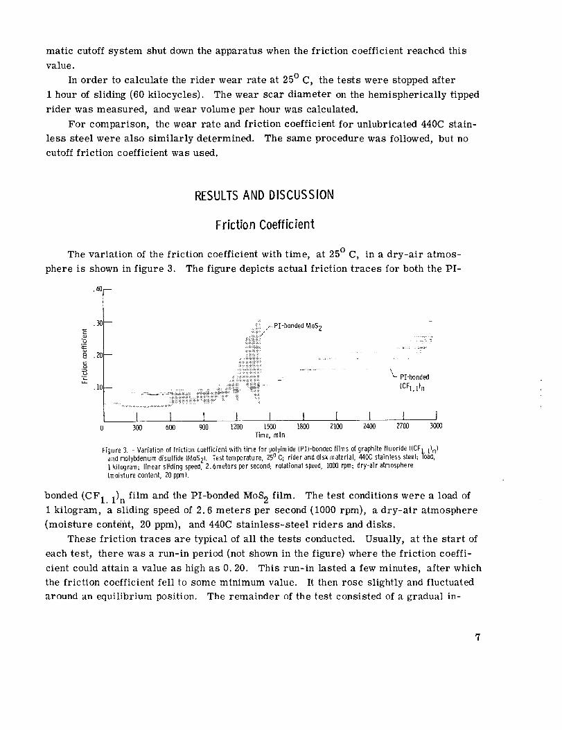
The variation of the friction coefficient with time, at 25 ° C, in a dry-air atmos-
phere is shown in figure 3. The figure depicts actual friction traces for both the PI-
.40--
.30
a_
'5
8 .20
i--u-
•10
.;i__PI-bondedMoS 2.:.::::::::,
::..:::::::::::::::::::::::::::::::
:-::::-::'<:::9
:.:<.:,:,:.:,:.:.:,:..:
!:!:::::::::::::::::::::::::::::::::
: : " .-.:....<..........,...,.......,.._..,...:.::::'_i::':':<<':';:::::::' ......
I l ] I I0 300 600 900 1200 t500 1800 2100
Time, rain
PI-bonded
(CFl.l)n
I I I I I2400 2700 3000
Figure 3. - Variation of friction coefficient with time for polyimide (PI)-bondedfilms of graphite fluoride ((CF] 1)n)and molybdenumdisulfide IMoS2). Testtemperature, 25o C; rider and disk mater a, ZlzlOCstainless steel; ]bad,1 kilogram; linear sliding speed, 2.6meters per second; rotational speed, 1000rpm; dry-air atmosphereImoisture content, 20 ppm).
bonded (CF1. 1) n film and the PI-bonded MoS 2 film. The test conditions were a load of
1 kilogram, a sliding speed of 2.6 meters per second (1000 rpm), a dry-air atmosphere
(moisture content, 20 ppm), and 440C stainless-steel riders and disks.
These friction traces are typical of all the tests conducted. Usually, at the start of
each test, there was a run-in period (not shown in the figure) where the friction coeffi-
cient could attain a value as high as 0.20. This run-in lasted a few minutes, after which
the friction coefficient fell to some minimum value. It then rose slightly and fluctuated
around an equilibrium position. The remainder of the test consisted of a gradual in-
crease in the value of the friction coefficient until the cutoff friction coefficient of 0.30was reached.
The friction coefficient of the PI-bonded (CF1.1)n film seemedto be characterizedby a more gradual increase with time thandid the PI-bondedMoS2 film. The frictioncoefficient of the PI-bondedMoS2 film at somepoint during the test suddenlybecameerratic (e. g., at 600 min in fig. 3). This erratic friction is probably due to metalliccontact through the lubricant film, and-the subsequentrehealing of the film due to addi-tional lubricant being brought into the contact region from the sides of the disk weartrack.
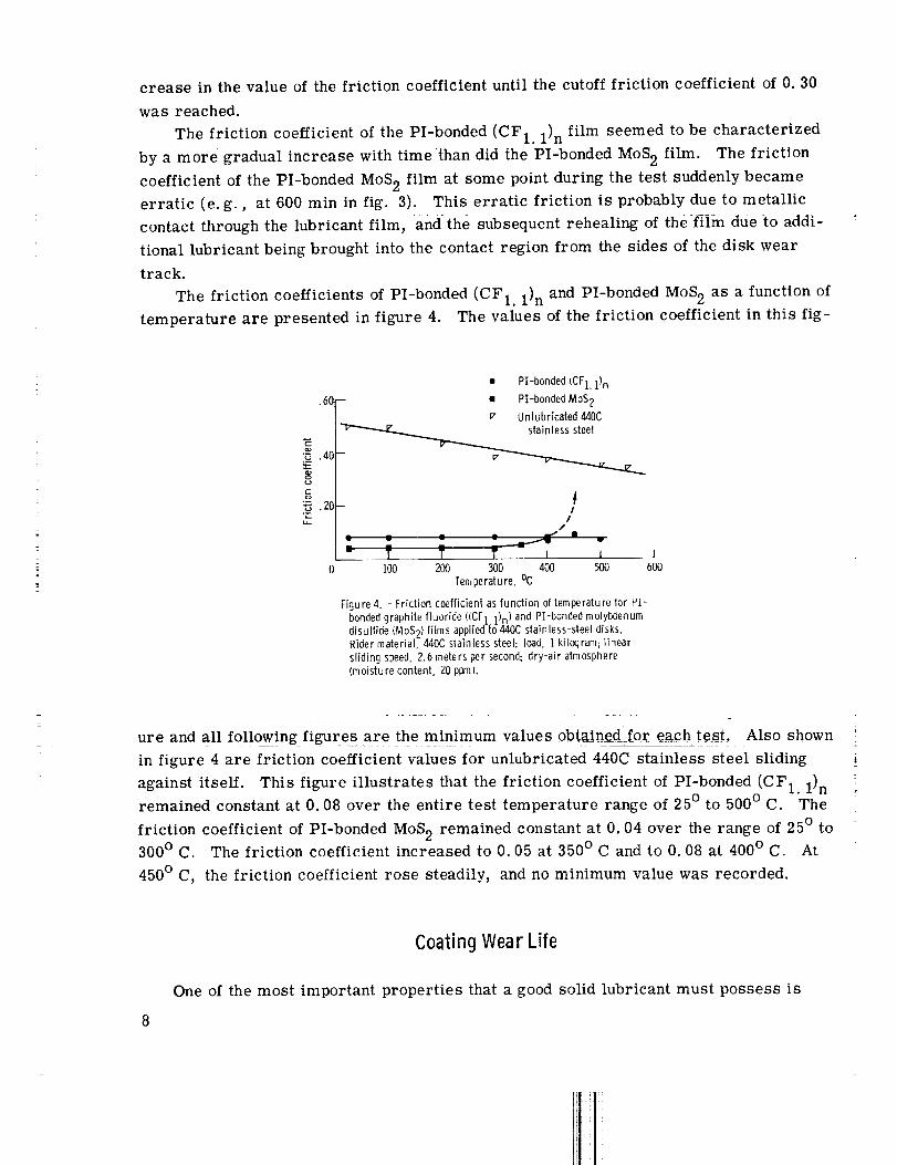
The friction coefficients of PI-bonded (CF1.1)n and PI-bondedMoS2 as a function oftemperature are presented in figure 4. The values of the friction coefficient in this fig-
.60
:__.4C
g
• Pl-bonded (CFI.l)n
-- • Pl-bonded MoS 2
v Unlubricated440C
I/
/
- T T T I i I100 200 300 400 500 600
Temperature, °C
Figure 4. - Friction coefficient as function of temperature for PI-
bonded graphite fluoride ((CF 1 1)n} and Pl-bonded molybdenum
disulfide (MoS21 films applied to 440C stainless-steel disks.Rider material, 440C stainless steel; load, i kilogram; linear
sliding speed, 2.6 meters per second; dry-air atmosphere
(moisture content, 20 ppml.
ure and all following figures are the minimum values 0btainedf0rea_h test. Also shown
in figure 4 are friction coefficient values for unlubricated 440C stainless steel sliding i
against itself. This figure illustrates thai the friction coefficient of PI-bonded (CF1.1) nremained constant at 0.08 over the entire test temperature range of 25 ° to 500 ° C. The
friction coefficient of PI-bonded MoS 2 remained constant at 0.04 over the range of 25 ° to300 ° C. The friction coefficient increased to 0.05 at 350 ° C and to 0.08 at 400 ° C. At
450 ° C, the friction coefficient rose steadily, and no minimum value was recorded.
Coating Wear Life
One of the most important properties that a good solid lubricant must possess is
the ability to remain intact on the surface to be lubricated for as long as possible. This
quality, the wear life of the lubricant film, can be designated either as the time or the
number of cycles until failure occurs.
Failure is an arbitrary term. It is usually the discretion of the experimentor which
determines the onset of failure. In this study, the criterion for failure was a friction
coefficient of 0.30. This value was less than the friction coefficient of unlubricated
440C stainless steel over the entire test temperature range.
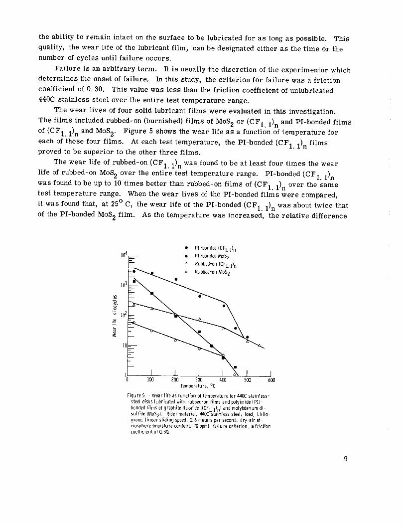
The wear lives of four solid lubricant films were evaluated in this investigation.
The films included rubbed-on (burnished) films of MoS 2 or (CF1.1) n and PI-bonded films
of (CF1.1)n and MoS 2. Figure 5 shows the wear life as a function of temperature for
each of these four films. At each test temperature, the PI-bonded (CF1.1) n filmsproved to be superior to the other three films.
The wear life of rubbed-on (CF1.1) n was found to be at least four times the wear
life of rubbed-on MoS 2 over the entire test temperature range. PI-bonded (CF1. 1) n
was found to be up to 10 times better than rubbed-on films of (CF1.1) n over the same
test temperature range. When the wear lives of the PI-bonded films were compared,
it was found that, at 25 ° C, the wear life of the PI-bonded (CF1.1) n was about twice that
of the PI-bonded MoS 2 film. As the temperature was increased, the relative difference
• PI-bonded (CFI.l)n
104 -- • PI-bonded MoS 2
-- " Rubbed-on (CFI.l)n
o Rubbed-on MoS 2
103 _ •
10__ • •
1
100 200 300 400 500
Temperature, °C
Figure 5. - Wear life as function of temperature for 440C stainless-
steel disks lubricated with rubbed-on films and polyimide (PI)-
bonded films of graphite fluoride ((CF 1 ])n ) and molybdenum di-sulfide (MoS2). Rider material, Zl40C _,tainless steel; load, 1 kilo-
gram; linear sliding speed, 2. 6 meters per second; dry-air at-mosphere (moisture content, 20 ppm); failure criterion, a friction
coefficient of 0. 50.
_ lo2
I6OO
9
between the wear lives became greater; and at 400 ° C, the difference was about a factor
of 60.
At 450 ° C, the wear life of both PI-bonded films dropped off. Upon examination of
the disks after test completion, it was found that the coatings had become powdery.
Thus, the upper temperature limit for these PI-bonded films, in a dry-air atmosphere,
is about 400 ° C. It is interesting to note that above 400 ° C the wear lives of the PI-
bonded films approached the values of the wear lives of their respective rubbed-on solid
lubricant films.
A comparison of the wear lives, at 25 ° C, for the four solid lubricant films is given
in table I. The wear life of a commercially available sodium silicate bonded MoS 2 lu-
TABLE I. - COMPARISON OF WEAR LIVES
AT 25 ° C OF FIVE LUBRICANT FILMS
[Dry-air atmosphere (moisture content,
20 ppm); 440C stainless-steel riders
and disks; 1-kg load; 2.6-m/sec
linear sliding speed. ]
Lubr_[cant film Wear life,
kilocycles
PI-bonded (CF1. 1)n
PI-bonded MoS 2
71-wt 9 MoS 2 - 7 wt _ graphite -
22-wt _ sodium silicate a
(CF1. 1)n rubbed fihn
MoS 2 rubbed film
2950
1400
500
230
60
acommercially available lubricant tested by
authors under above conditions.
bricant, which was tested under the same conditions, is also presented.
The rubbed-on films gave the shortest wear lives at 25 ° C. The wear life of rubbed
MoS 2 was 60 kilocycles; rubbed-on (CF1.1)n films gave much better results, with a
wear life of 230 kilocycles. The commercially available sodium silicate bonded MoS 2
film proved to be better than either of the rubbed-on films; its wear life was 500 kilo-
cycles.
By using polyimide as the binder material for MoS2, further improvement in the
wear life was achieved. The wear life for this film was 1400 kilocycles. When (CF1.1)n
was substituted for MoS 2 in the polyimide film formulation, the results were even better.
The wear life for these PI-bonded (CF1.1)n films was 2950 kilocycles.
10
It is important to note that no attempt was made to optimize the weight ratio of
(CF1. 1)n to polyimide in formulating the film. An optimization study could result in anevenbetter formulation.
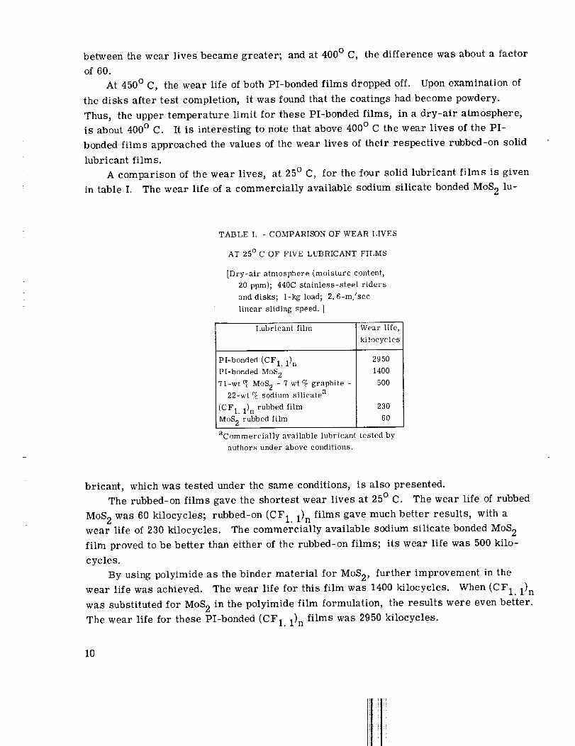
The number of kilocycles at which the friction coefficient reachedvalues of 0. 10,0.20, and 0.30 are given in table II. This information is given for each of the four lu-
TABLE II. - NUMBER OF REVOLUTIONS ELAPSED BEFORE FRICTION COEFFICIENT
OF FOUR DIFFERENT FILMS REACHED VALUES OF 0. I0, 0.20, AND 0.30
[Dry-air atmosphere (moisture content, 20 ppm); 440C stainless-steel disks and riders;
1-kg load; 2.6-m/sec sliding speed• ]
(a) Test temperature, 25 °C.
Friction
coeffi-
cient
PI-bonded PI-bonded Rubbed Rubbed
(CFI. 1)n M°S 2 (CFI. l)n MoS 2
Number of revolutions, kilocycles
0. 10
• 20
.30
1300 1000 20
2250 1250 120
2950 1400 230
(c) Test temperature, 200 ° C.
0.10
• 20
.30
1000 60 20
1350 70 30
1800 100 100
(e) Test temperature, 400 ° C.
0. 10 100
.20 150
.30 230
aFailed immediately.
<71 20
2 30
4 40
57
58
60
Friction
coeffi-
cient
0. 10
• 20
• 30
0. 10
• 20
• 30
(b) Test temperature, 100 °C.
Pl-bonded PI-bonded Rubbed Rubbed
(CFI. l)n MoS 2 (CFI. l)n M°S 2
Number of revolutions, kilocycles
2300
2550
2750
450
500
550
60 27
100 30
180 31
(d) Test temperature, 300 °C.
350
4O0
450
20
25
30
10
5O
8O
(f) Test temperature, 500 °C.
7
10
20
(a)
(a)(a)
lO ] (a)14 (a)
16 (a)
bricant films and for each of the test temperatures of 25 °, 100 °, 200 °, 300 °, 400 °,
and 500 ° C. The wear-life ranking of the four films is the same at all three values of
friction coefficient. Therefore, the choice of a friction coefficient of 0. 10 or 0.20 in-
stead of 0.30 as the failure criterion would not alter the conclusions concerning the rel-
ative durability of the coatings.
Wear
In addition to providing a low friction coefficient and a long wear life, a good solid
lubricant should also minimize wear. Thus, a series of experiments were performed
to compare the wear occurring on the sliding riders.
11
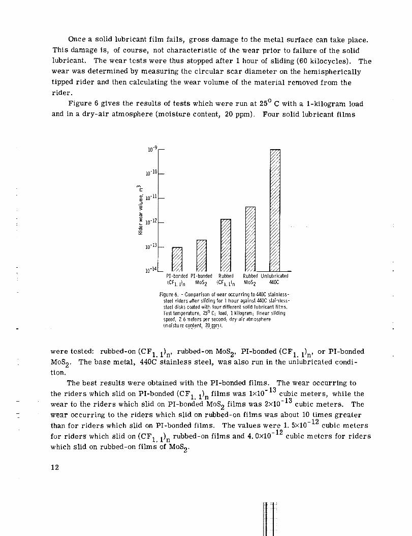
Oncea solid lubricant film fails, gross damageto the metal surface can take place.This damageis, of course, not characteristic of the wear prior to failure of the solidlubricant. The wear tests were thus stoppedafter 1 hour of sliding (60 kilocycles). Thewear wasdetermined by measuring the circular scar diameter on the hemisphericallytipped rider and thencalculating the wear volume of the material removed from therider.
Figure 6 gives the results of tests which were run at 25° C with a 1-kilogram loadand in a dry-air atmosphere (moisture content, 20ppm). Four solid lubricant films
%
10-9
i0-i0
_" 10-11
_ 10-12
10-13
lO-IZl
///
////////////
_//////
///i1t 1//
__ _ /// /.I/iit " " "/// / 11/ / / ///., . /// //// / / /// ///
N...../// /// _
i/i /////////
iii///
PI-bonded PI-bonded Rubbed Rubbed Unlubricated
(CFI. lln MoS2 (CFI. lln MoS2 _OC
Figure 6. - Comparison of wear occurring to _OC stainless-steel riders after slidingfor 1 hour against 440C stainless-steel disks coated with four different solid lubricant films.Testtemperature, 250C; load, 1 kilogram; linear slidingspeed, 2.6 meters per second; dry-air atmosphere(moistu re content, 20 ppm1.
were tested: rubbed-on (CF1.1)n , rubbed-on MoS2, PI-bonded (CF1.1)n , or PI-bonded
MoS 2. The base metal, 440C stainless steel, was also run in the unlubricated condi-tion.
The best results were obtained with the 1)I-bonded films. The wear occurring to
the riders which slid on PI-bonded (CF1. 1)n films was lxl0-13 cubic meters, while the
wear to the riders which slid on PI-bonded MoS 2 films was 2x10-13 cubic meters. The
wear occurring to the riders which slid on rubbed-on films was about 10 times greater
than for riders which slid on PI-bonded films. The values were 1.5x10 -12 cubic meters
for riders which slid on (CF1.1)n rubbed-on films and 4.0xl0 -12 cubic meters for riders
which slid on rubbed-on films of MoS 2.
12
I 111
i| i
:tiI i
The wear of riders sliding on the unlubricated 440C stainless steel was lxl0 -9
cubic meters per hour of sliding time (60 kilocycles); the PI-bonded films thus reduced
the wear to 1/10 000th that of the unlubricated surface.
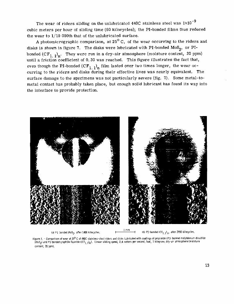
A photomicrographic comparison, at 25 ° C, of the wear occurring to the riders and
disks is shown in figure 7. The disks were lubricated with PI-bonded MoS2, or PI-
bonded (CF1.1)n . They were run in a dry-air atmosphere (moisture content, 20 ppm)
until a friction coefficient of 0.30 was reached. This figure illustrates the fact that,
even though the PI-bonded (CF1.1) n film lasted over two times longer, the wear oc-
curring to the riders and disks during their effective lives was nearly equivalent. The
surface damage to the specimens was not particularly severe (fig. 7). Some metal-to-
metal contact has probably taken place, but enough solid lubricant has found its way into
the interface to provide protection.
Imm(a) PI-bonded MoS2, after 1400 kilocycles. I I (b) P'[-bonded (CFl. 1}n , after 2950 kilocycles.
Figure 1. - Comparison of wear at 25o C of 4zlOCstainless-steel riders and disks lubricated with coatings of polyimide (PI)-bondecl molybdenum disulfide
IMoS 2) and PI-bonded graphite fluoride ((CF]. 1)n). Linear sliding speed, 2.6 meters per second; load, 1 kilogram; drT-air atmosphere (moisture
content, 20 ppm).
13
SUMMARY OF RESULTS
A study was made of graphite fluoride as a solid lubricant in a polyimide binder.
The results were as follows:
1. Polyimide (PI) is a suitable binder material for the solid lubricant graphite
fluoride ((CF1. 1)n ).
2. The wear life of PI-bonded (CF1. 1)n is superior to the wear life of similar films
of PI-bonded molybdenum disulfide (MoS2).
3. The wear life of PI-bonded (CF1.1)n is 10 times greater than the wear life of
rubbed-on films of either (CF1.1)n or MoS 2.
4. The PI-bonded (CF1.1)n films performed exceptionally well at high temperatures;
at 400 ° C for example, they lasted about 60 times longer than PI-bonded MoS 2 films.
5. The rider wear rates of the PI-bonded (CF1.1)n and PI-bonded MoS 2 films were
nearly equivalent at 25 ° C.
6. The reduction in the wear life of PI-bonded (CF1.1)n above 400 ° C is due to the
degradation of the polyimide.
Lewis Research Center,
National Aeronautics and Space Administration,
Cleveland, Ohio, December 13, 1971,
132-15.
REFERENCES
1. Fusaro, Robert L. ; and Sliney, Harold E. : Preliminary Investigation of Graphite
Fluoride (CFx) n as a Solid Lubricant. NASA TN D-5097, 1969. (Also Graphite
Fluoride (CFx) n - A New Solid Lubricant. ASLE Trans., vol. 13, no. 1, Jan.
1970, pp. 56-65.)
2. E. I. du Pont de Nemours & Co.: Polyimides. British Patent 982, 914 (Concord-
ance U.S. Patent 3, 179,633), Feb. 10, 1965.
3. Buckley, D. H. ; and Johnson, R. L. : Degradation of Polymeric Compositions in
Vacuum to 10 -9 mm Hg in Evaporation and Sliding Friction Experiments. SPE
Trans., vol. 4, no. 4, Oct. 1964, pp. 306-314.
4. Buckley, Donald H. : Friction and Wear Characteristics of Polyimide and Filled
Polyimide Compositions in Vacuum (10 -10 mm Hg). NASA TN D-3261, 1966.
5. Jones, William R., Jr. ; Hady, William F. ; and Johnson, Robert L. : Friction and
Wear of Poly (Amide-Imide), Polyimide, and Pyrrone Polymers at 2600 C (500 ° F)
in Dry Air. NASA TN D-6353, 1971.
14
6. Loomis, William R.; Johnson, Robert L. ; and Lee, John: High-Temperature Poly-imide Hydraulic Actuator RodSealsfor AdvancedAircraft. NASATM X-52889,1970.
7. Campbell, M. ; and Hopkins, V. : Developmentof Polyimide BondedSolid Lubricants.Lub. Eng., vol. 23, no. 7, July 1967, pp. 288-294.
8. Schachner, Herbert: CarbonMonofluoride as Lubricant. GermanPatent 1,074,795(ConcordanceBritish Patent 877122and U. S. Patent 2,993,567), Feb. 4, 1960.
9. Ishikawa, T. ; and Shimada,T. : Application of Polycarbon Monofluoride. Pre-sentedat the Fluorine Symposium, Moscow, 1969.
10. Gisser, H. ; Petronio, M. ; and Shapiro, A. : Graphite Fluoride as a Solid Lubri-cant. Proceedings of the International Conference onSolid Lubrication. ASLESP-3, 1971.
11. Hawkins, W. L. : Thermal and Oxidative Degradationof Polymers. SPE Trans.,vol. 4, no. 3, July 1964, pp. 187-192.
12. Mark, H. F. ; and Atlas, S. H. : Principles of Polymer Stability. Polymer Eng.Sci., vol. 5, no. 3, July 1965, pp. 204-207.
13. Carothers, Wallace H.: Linear Polyamides Suitable for Spinninginto Strong PliableFibers. U.S. Patent 2, 130,523, Sept. 20, 1938.
14. Bower, G. M.; and Frost, L. W.: Aromatic Polyimides. J. Polymer Sci., Pt. A,vol. 1, no. 10, 1963, pp. 3135-3150.
15. Floyd, Don E. : Polyamide Resins. Seconded., Reinhold Pub. Co., 1966.
16. Edwards, Walter M. ; and Robinson, Ivan M. : Polyimides of Pyrometallic Acid.U.S. Patent 2,710, 853, June 14, 1955.
17. Edwards, Walter M. ; and Endrey, Andrew L. : Polyimides. British Patent 903,271(ConcordanceGermanPatent 1202981),Aug. 15, 1962.
18. Sroog, C. E.; Endrey, A. L. ; Abramo, S. V.; Berr, C. E.; Edwards, W. M. ;and Olivier, K. L. : Aromatic Polypyromellitimides from Aromatic PolyamicAcids. J. Polymer Sci., Pt. A, vol. 3, no. 4, 1965, pp. 1373-1390.
19. Heacock, J. F. ; and Berr, C. E. : Polyimides- New High Temperature Polymers:H-Film, A Polypyromellitimide Film. SPETrans., vol. 5, no. 2, Apr. 1965,pp. 105-110.
20. Adrova, N. A. ; Bessonov, M. I.; Laius, L. A. ; and Rudakov,A. P. (Kurt Gin-gold, trans.): Polyimides: A New Class of Thermally StablePolymers. Tech-nomic Publ. Co., 1970.
15
21. Devine, M. J.; and Kroll, A. E. : Aromatic Polyimide Compositions for Solid Lu-
brication. Lub. Eng., vol. 20, no. 6, June 1964, pp. 225-230.
22. Todd, N. W. ; and Wolff, F. A. : Polyimide Plastics Withstand High Temperatures.
Materials in Des. Eng., vol. 60, no. 2, Aug. 1964, pp. 86-91.
23. Bower, G. Ronald: What Engineers Should Know about Self-Lubricating Plastics.
Metal Prog., vol. 88, no. 3, Sept. 1965, pp. 106, 108, 110, 112, 114.
24. Freeman, James H. ; Frost, Lawrence W. ; Bower, George M. ; and Traynor,
Edward J. : Resins and Reinforced Plastic Laminates for Continuous Use at
650 ° F. SPE Trans., vol. 5, no. 2, Apr. 1965, pp. 75-83.
16 NASA-Langley, 1972 -- 15 E-6694

![Graphite and Hybrid Nanomaterials as Lubricant Additives · interaction between two mica surfaces coated with cerium oxide (CeO2) has been reported to be profound [38]. Surface potential](https://img.pdfslide.net/doc/110x75/60643816275b9976cf6d2762/graphite-and-hybrid-nanomaterials-as-lubricant-additives-interaction-between-two.jpg)