Embed Size (px)
Citation preview

GREENIDGE MULTI-POLLUTANT CONTROL PROJECT Final Public Design Report
Principal Author Daniel P. Connell
January 2009
U.S. Department of Energy Cooperative Agreement DE-FC26-06NT41426
CONSOL Energy Inc.
Research & Development 4000 Brownsville Road South Park, PA 15129
AES Greenidge LLC
590 Plant Road Dresden, NY 14441
Babcock Power Environmental Inc.
5 Neponset Street Worcester, MA 01615

DISCLAIMER
This report was prepared as an account of work sponsored by an agency of the United States Government. Neither the United States Government nor any agency thereof, nor any of their employees, makes any warranty, express or implied, or assumes any legal liability or responsibility for the accuracy, completeness, or usefulness of any information, apparatus, product, or process disclosed, or represents that its use would not infringe privately owned rights. Reference herein to any specific commercial product, process, or service by trade name, trademark, manufacturer, or otherwise does not necessarily constitute or imply its endorsement, recommendation, or favoring by the United States Government or any agency thereof. The views and opinions of authors expressed herein do not necessarily state or reflect those of the United States Government or any agency thereof.
NOTICE
The drawing titled “AES Greenidge #4, Dresden, New York, NOxOUT Utility System, System Overview Sheet 1” in Appendix C is Copyright © 2009 Fuel Tech, Inc. This paper was written with the support of the U.S. Department of Energy under Contract No. DE-FC26-06NT41426. The Government reserves for itself and others acting on its behalf a royalty-free, nonexclusive, irrevocable, worldwide license for Governmental purposes to publish, distribute, translate, duplicate, exhibit, and perform this copyrighted paper.
i

ABSTRACT
The Greenidge Multi-Pollutant Control Project is being conducted as part of the U.S. Department of Energy’s Power Plant Improvement Initiative to demonstrate an innovative combination of air pollution control technologies that can cost-effectively reduce emissions of SO2, NOx, Hg, acid gases (SO3, HCl, and HF), and particulate matter from smaller coal-fired electric generating units (EGUs). The multi-pollutant control system includes a NOxOUT CASCADE® hybrid selective non-catalytic reduction (SNCR) / in-duct selective catalytic reduction (SCR) system to reduce NOx emissions by ≥60%, followed by a Turbosorp® circulating fluidized bed dry scrubbing system to reduce emissions of SO2, SO3, HCl, and HF by ≥95%. Mercury removal of ≥90% is also targeted via the co-benefits afforded by the in-duct SCR, dry scrubber, and baghouse and by injection of activated carbon upstream of the scrubber, if required. The technology is particularly well suited, because of its relatively low capital and maintenance costs and small space requirements, to meet the needs of coal-fired units with capacities of 50-300 MWe. There are about 400 such units operating in the United States that currently are not equipped with SCR or flue gas desulfurization (FGD) systems. These smaller units are a valuable part of the nation’s energy infrastructure, constituting more than 55 GW of installed capacity. However, with the onset of various state and federal environmental actions requiring deep reductions in emissions of SO2, NOx, and mercury, the continued operation of these units increasingly depends upon the ability to identify viable air pollution control retrofit options for them. The large capital costs and sizable space requirements associated with conventional technologies such as SCR and wet FGD make these technologies unattractive for many smaller units. The Greenidge Project aims to confirm the commercial readiness of an emissions control system that is specifically designed to meet the environmental compliance requirements of these smaller coal-fired EGUs. The multi-pollutant control system was installed and tested on the AES Greenidge Unit 4 (Boiler 6) by a team including CONSOL Energy Inc. as prime contractor, AES Greenidge LLC as host site owner, and Babcock Power Environmental Inc. as engineering, procurement, and construction contractor. About 44% of the funding for the project was provided by the U.S. Department of Energy, through its National Energy Technology Laboratory, and the remaining 56% was provided by AES Greenidge. AES Greenidge Unit 4 is a 107 MWe (Energy Information Administration net winter capacity, pre-project), 1953 vintage, tangentially-fired, reheat unit that is representative of many of the 400 smaller coal-fired units identified above. Start-up of the multi-pollutant control system was completed in March 2007, and the system was then demonstrated over an approximately 18-month period while the unit fired 2-4% sulfur eastern U.S. bituminous coal and co-fired up to 10% biomass. This Final Public Design Report is the last in a series of two reports describing the design of the multi-pollutant control facility that is being demonstrated at AES Greenidge. Its purpose is to consolidate for public use all available nonproprietary design and cost information on the Greenidge Multi-Pollutant Control Project. The Final Public Design Report builds upon the Preliminary Public Design Report, which was released in May 2007, to provide a comprehensive description of the final, as-built design of the demonstration facility at AES Greenidge. The capital cost and projected operating costs of the multi-pollutant control system are also discussed. The design and cost information summarized here is intended to help inform the decision making of generators seeking affordable air emissions control retrofit options for their smaller coal-fired units.
ii

TABLE OF CONTENTS
1. Executive Summary 1
2. Introduction 3 2.1 The Power Plant Improvement Initiative 3 2.2 The Greenidge Multi-Pollutant Control Project 4 2.3 Host Site Information 6
3. Technology Overview 8 3.1 Process Concept 8
3.1.1 NOx Control 8 3.1.2 SO2, SO3, HCl, HF, and Particulate Matter Control 11 3.1.3 Mercury Control 13
3.2 Design Objectives 14 3.2.1 Deep Emission Reductions 14 3.2.2 Low Capital Costs 15 3.2.3 Small Space Requirements 16 3.2.4 Applicability to High-Sulfur Coals 16 3.2.5 Low Maintenance Requirements 17 3.2.6 Operational Flexibility 17
3.3 Design Considerations 19 3.3.1 Coal and Ash Characteristics 19 3.3.2 Baseline NO Concentration 20 3.3.3 Temperature Profile in the Furnace 20 3.3.4 Flue Gas Residence Time and Flow Profile in the Furnace 20 3.3.5 CO Concentrations in the Furnace 21 3.3.6 Available Space Between the Economizer and Air Heater 21 3.3.7 Flue Gas Temperature at the Economizer Outlet 21 3.3.8 Flue Gas Homogeneity at the SCR Inlet 22 3.3.9 Large Particle Ash 22 3.3.10 Amount of Allowable Ammonia Slip 22 3.3.11 Approach to Adiabatic Saturation in the Absorber Vessel 23 3.3.12 Hydrated Lime Supply 23 3.3.13 Increased Solids Loading to the Baghouse 24 3.3.14 Pressure Drop Across the System 24
3.4 Project Uniqueness and Uncertainties 24
4. System Design for AES Greenidge Unit 4 26 4.1 Design Basis 26 4.2 Description by Major Process Component 27
4.2.1 Selective Non-Catalytic Reduction System 27 4.2.2 In-Duct Selective Catalytic Reduction Reactor 30 4.2.3 Activated Carbon Injection System 33 4.2.4 Turbosorp® Circulating Fluidized Bed Dry Scrubber 33 4.2.5 Process Water System 36 4.2.6 Lime Storage, Hydration, and Injection System 36 4.2.7 Baghouse 37 4.2.8 Ash Recirculation System 38 4.2.9 Booster Fan 38
iii

4.3 Balance of Plant Considerations 39 4.3.1 Ductwork 39 4.3.2 Civil and Structural 39 4.3.3 Instruments and Controls 42 4.3.4 Electrical 42 4.3.5 Other Utilities 42 4.3.6 Byproducts 43 4.3.7 Out-of-Scope Modifications 44
4.3.7.1 Combustion Modifications 45 4.3.7.2 Air Preheater Basket Modifications 45
5. Process Economics for AES Greenidge Unit 4 46 5.1 Capital Costs 46 5.2 Fixed Operating and Maintenance Costs 48 5.3 Variable Operating and Maintenance Costs 48 5.4 Levelized Costs 50
6. Conclusions 53
ACRONYMS AND ABBREVIATIONS 54
REFERENCES 57 APPENDIX A - Process Flow Diagrams 59 APPENDIX B - List of Major Equipment 62 APPENDIX C - Piping & Instrument Diagrams 64 APPENDIX D - General Arrangement Drawings 77
iv

LIST OF FIGURES
Figure 1. Overall project schedule. 5
Figure 2. Aerial photograph of the AES Greenidge plant, as viewed from the south prior to the multi-pollutant control project. 7
Figure 3. Schematic of the multi-pollutant control process being demonstrated at AES Greenidge Unit 4. 8
Figure 4. Conceptual depiction of the effect of temperature on urea utilization and ammonia slip in SNCR, and the implications of this effect for hybrid SNCR/SCR design. 10
Figure 5. Conceptual illustration of the Delta Wing™ static mixing technology. 11
Figure 6. Schematic of the Turbosorp® circulating fluidized bed dry scrubbing system. Red, blue, and green arrows indicate the paths of solids, liquids, and gases, respectively, through the system. 13
Figure 7. Operating strategy for the hybrid NOx control system being demonstrated at AES Greenidge. 18
Figure 8. Example of CFD modeling results used in the design of the hybrid NOx control system for AES Greenidge Unit 4 (Boiler 6). Shown are temperature and velocity profiles for a case in which the unit is operating at 103% of its MCR. 28
Figure 9. Photograph showing the urea storage tank and HFD module at AES Greenidge Unit 4. 29
Figure 10. Photograph of the physical flow model used to design the in-duct SCR for AES Greenidge Unit 4 (courtesy of Ruscheweyh Consult GmbH). 31
Figure 11. Schematic of the large particle ash removal system that was installed above the in-
duct SCR reactor at AES Greenidge Unit 4. 32
Figure 12. Photograph of the in-duct SCR reactor at AES Greenidge Unit 4. 32
Figure 13. Photograph of the activated carbon injection system at AES Greenidge Unit 4. 33
Figure 14. Photograph of the Turbosorp® circulating fluidized bed dry scrubbing system, including ancillary equipment, at AES Greenidge Unit 4. 34
Figure 15. Process control schematic showing major control loops for the Turbosorp circulating fluidized bed dry scrubber at AES Greenidge Unit 4. Lime injection control is shown in green; water injection control is shown in blue; solid product recycle control is shown in red; and solid product rejection control is shown in orange. 35
®
Figure 16. Photograph of one of the air slide conveyers at AES Greenidge Unit 4. 38
Figure 17. Photograph taken prior to the start of construction of the site for the outdoor portion of the multi-pollutant control system, as viewed from the southwest. 40
Figure 18. Effect of coal sulfur content on SO2 control costs for 95% SO2 removal efficiency. 53
v

LIST OF TABLES
Table 1. Characteristics of existing Turbosorp® installations and of the AES Greenidge design. 25
Table 2. Assumed fuel characteristics (as fired) for the design case. 27
Table 3. Emission performance targets for the design case. 27
Table 4. Water requirements for operation of the multi-pollutant control system at AES Greenidge. 43
Table 5. Projected composition of the fly ash / scrubber byproduct discharged from the baghouse. 44
Table 6. Plant performance assumptions used in the economic analysis of the AES Greenidge Unit 4 design case. 47
Table 7. Estimated capital costs for the multi-pollutant control system at AES Greenidge Unit 4. Costs are expressed in 2005 dollars. 47
Table 8. Estimated fixed operating and maintenance costs for the multi-pollutant control system at AES Greenidge Unit 4. 48
Table 9. Unit costs used in variable O&M cost calculations. 49
Table 10. Estimated variable operating and maintenance costs for the multi-pollutant control system at AES Greenidge Unit 4. 49
Table 11. Financial assumptions used for levelized capital cost calculations. 50
Table 12. Estimated levelized costs for the multi-pollutant control system at AES Greenidge Unit 4. Costs are expressed in constant 2005 dollars. 50
Table 13. Estimated levelized costs for the hybrid NOx control system (including the combustion modifications) at AES Greenidge Unit 4. Costs are expressed in constant 2005 dollars. 51
Table 14. Estimated levelized costs for the circulating fluidized bed dry scrubbing system at AES Greenidge Unit 4. Costs are expressed in constant 2005 dollars. 51
Table 15. Estimated levelized costs for the activated carbon injection system at AES Greenidge Unit 4. Costs are expressed in constant 2005 dollars. 51
vi

1. Executive Summary As part of the Greenidge Multi-Pollutant Control Project, CONSOL Energy Inc. Research & Development, AES Greenidge LLC, and Babcock Power Environmental Inc. (BPEI) installed and tested an innovative, integrated combination of technologies on one of the nation’s smaller existing coal-fired power plants - the 107-MWe AES Greenidge Unit 4 (Boiler 6). The overall goal of this approximately 2.5-year project is to demonstrate that this multi-pollutant control system, which includes a NOxOUT CASCADE® hybrid selective non-catalytic reduction (SNCR) / selective catalytic reduction (SCR) system and a Turbosorp® circulating fluidized bed dry scrubbing system with baghouse ash recycling and activated carbon injection, can cost-effectively reduce emissions of nitrogen oxides (NOx), sulfur dioxide (SO2), mercury (Hg), particulate matter (PM), and acid gases, including sulfur trioxide (SO3), hydrogen chloride (HCl), and hydrogen fluoride (HF), from coal-fired electric generating units (EGUs) with capacities of 50 MWe to 600 MWe. The project is being conducted as part of the U.S. Department of Energy’s (DOE’s) Power Plant Improvement Initiative (PPII), which is managed by its National Energy Technology Laboratory (NETL). Although the multi-pollutant control system being demonstrated at AES Greenidge is applicable to units with capacities of 50-600 MWe, its potential benefits are greatest for units in the lower half of this size range. There are about 400 coal-fired units operating in the United States with capacities of 50-300 MWe that currently are not equipped with SCR or flue gas desulfurization (FGD) systems. These smaller units, which represent more than 55 GW of installed generating capacity, are increasingly vulnerable to retirement or fuel switching as a result of progressively more stringent state and federal environmental regulations. The Greenidge Project is demonstrating the commercial readiness of an emissions control system that is particularly suited, because of its low capital and maintenance costs and small space demands, to meet the requirements of this large group of existing electric generating units. The Greenidge Multi-Pollutant Control Project was funded by the DOE (43.8%) and by AES Greenidge (56.2%). The project is the first to demonstrate: • Full-load NOx emissions of ≤0.10 lb/mmBtu using a NOxOUT CASCADE® hybrid SNCR/SCR system, in
combination with low-NOx combustion technology, on a unit firing >2%-sulfur coal and biomass • SO2 and acid gas (SO3, HCl, HF) removal of ≥95% using a Turbosorp® circulating fluidized bed dry
scrubber on a unit firing >2%-sulfur U.S. bituminous coal • Mercury reduction of ≥90% via the co-benefits afforded by the in-duct SCR and Turbosorp® (with
baghouse) systems and by activated carbon injection, if needed This Final Public Design Report is the last in a series of two reports that together consolidate for public use all available nonproprietary design and cost information on the Greenidge Multi-Pollutant Control Project. The design of the multi-pollutant control system was developed in response to the following overall objectives, which are consistent with the needs of smaller coal-fired units in an increasingly stringent regulatory environment: • Achieve deeper emission reductions than those afforded by conventional low-capital-cost emissions
control options (e.g., low-NOx burners or stand-alone SNCR for NOx control and combustion of low-sulfur coal or use of sorbent injection for SO2 control)
• Require less capital investment than the amount needed for conventional technologies (e.g., full-scale SCR systems, wet scrubbers) that are capable of deep air emissions reductions
• Require significantly less space than the amount needed for conventional technologies (e.g., full-scale SCR systems, wet scrubbers) that are capable of deep air emissions reductions
• Provide applicability to a wide range of coal types, including high-sulfur (i.e., >2%-sulfur) coals • Minimize maintenance requirements • Maintain operational flexibility, including turndown capabilities for units that regularly cycle their loads in
response to electricity demand The design for AES Greenidge Unit 4 is based on the use of a 2.9%-sulfur (range: 2-4%) bituminous coal, with up to 10% biomass co-firing, and a pre-project baseline NOx emission rate of ~0.30 lb/mmBtu (the unit
1
was equipped with a separated overfire air system prior to the project). NOx control is the first step in the multi-pollutant control process and is accomplished using urea-based, in-furnace SNCR followed by a single-layer SCR reactor that is installed in a modified section of the ductwork between the unit’s economizer and air heaters. The SCR process is fed by ammonia slip from the SNCR process; static mixers located just upstream of the SCR are used to homogenize the velocity, temperature, and composition of the flue gas to promote optimal ammonia utilization and NOx reduction across the relatively small SCR catalyst. A large particle ash (LPA) removal system, including a screen, sootblowers, and vacuum ports, was installed above the SCR after start-up (outside of the scope of the DOE project) to prevent LPA from accumulating in the catalyst. The hybrid NOx control system at AES Greenidge Unit 4 also includes combustion modifications (installed outside of the scope of the DOE project) to achieve further reductions in NOx emissions and to improve the performance of the hybrid SNCR/SCR system. Hence, a full-load NOx emission rate of ≤0.10 lb/mmBtu is expected to result from the combination of the combustion modifications, which are designed to produce NOx emissions of 0.25 lb/mmBtu, the SNCR, which is designed to reduce NOx by ~42% to 0.144 lb/mmBtu, and the SCR, which is designed to further reduce NOx by ≥31% to ≤0.10 lb/mmBtu. Emissions of SO2 and other acid gases are reduced by ≥95% in the Turbosorp® circulating fluidized bed dry scrubbing system, which is installed downstream of the air heaters. In the Turbosorp® system, water and dry hydrated lime, which is supplied from an on-site hydrator installed as part of the project, are injected separately into a fluidized bed absorber, where the flue gas is evaporatively cooled and brought into intimate contact with the hydrated lime reagent in a fast fluidized bed. The hydrated lime reacts with the acidic constituents of the flue gas (i.e., SO2, SO3, HCl, and HF) to form dry solid products, which are separated from the flue gas in a new pulse-jet baghouse and recycled to the absorber via air slides at a high ratio to the inlet solids in order to maximize pollutant removal and lime utilization. The Greenidge multi-pollutant control process, with its combination of an in-duct SCR, hydrated lime-based scrubber, and baghouse, is designed to achieve high mercury removal efficiency without any activated carbon injection when applied to bituminous coal-fired units. However, to ensure ≥90% Hg capture, the AES Greenidge Unit 4 installation also includes an activated carbon injection system. Relative to simple duct injection, very effective utilization of the activated carbon and high mercury capture are expected to result from the high solids recycle ratio, long solids residence time, and low temperature (~160oF) provided by the circulating fluidized bed dry scrubber and baghouse. A new booster fan is included to overcome the increased pressure drop created by the addition of the static mixers, LPA screen, SCR catalyst, circulating fluidized bed dry scrubber, baghouse, and longer ductwork runs. This booster fan accounts for much of the auxiliary load associated with the multi-pollutant control system, which has reduced the unit’s net electric output by ~1.8%. The design includes turndown capabilities for the SNCR and Turbosorp® systems, enabling continued emissions reduction at reduced loads. Balance of plant impacts, including requirements for ductwork, civil and structural work, instruments and controls, utilities, and byproduct handling, are also accounted for. The total plant cost for the multi-pollutant control system (including the combustion modifications and LPA removal system) at AES Greenidge Unit 4 was $349/kW (2005 dollars), and the system occupies less than 0.5 acre of land. The estimated levelized cost (including capital costs and fixed and variable operating and maintenance costs) associated with the system is $14.62/MWh. Estimated costs for urea in the hybrid SNCR/SCR system and for lime and waste disposal in the Turbosorp® system, which are the costs that figure into the unit’s dispatch calculations, are $0.62/MWh ($834/ton of NOx removed) and $4.53/MWh ($241/ton of SO2 removed), respectively. The cost for SO2 control also covers SO3, HCl, HF, and improved primary particulate matter control, which are co-benefits of the Turbosorp® system. Mercury control would be expected to cost between $0 and $5,872 per pound of Hg removed, depending on the amount of co-benefit capture afforded by the NOx and SO2 control systems. At AES Greenidge, the incremental cost of Hg control has been $0, because no activated carbon injection has been required to achieve >90% Hg removal. Installation of the multi-pollutant control system will enable AES Greenidge Unit 4 to satisfy its air emissions requirements while remaining profitable, thereby allowing a 20-30 year life extension for the unit.
2

2. Introduction The Greenidge Multi-Pollutant Control Project is being conducted under U.S. Department of Energy Cooperative Agreement No. DE-FC26-06NT41426 to demonstrate the full-scale, retrofit application of a multi-pollutant control system that is designed to reduce emissions of NOx, SO2, Hg, particulate matter, and acid gases, including SO3, HCl, and HF, from coal-fired units with capacities of 50–600 MWe. The multi-pollutant control system, which includes the combination of a NOxOUT CASCADE® hybrid selective non-catalytic reduction / selective catalytic reduction system and a Turbosorp® circulating fluidized bed dry scrubbing system with baghouse ash recycling and activated carbon injection, was installed and tested on the coal-fired, 107 MWe AES Greenidge Unit 4 (Boiler 6) in Dresden, New York. The project is part of the DOE’s Power Plant Improvement Initiative, with an overall objective of demonstrating that the combination of technologies installed at AES Greenidge provides an affordable means for achieving deep reductions in the emissions of a number of pollutants from smaller coal-fired electric generating units, allowing these units to continue to produce low-cost electricity in an environment of increasingly stringent air emissions regulations. This Final Public Design Report is the last in a series of two reports describing the design of the multi-pollutant control facility at AES Greenidge. Its purpose is to consolidate for public use all available nonproprietary design information on the Greenidge Multi-Pollutant Control Project. This report builds upon the Preliminary Public Design Report, which was issued in May 2007, to reflect the final, as-built design of the facility and to incorporate data on capital costs and projected operating costs. Because these reports are limited to nonproprietary information, they do not provide all of the information required to replicate the design of the multi-pollutant control system. Rather, they are intended to serve as references highlighting important design and cost considerations involved in commercial-scale installations of the system.
2.1 The Power Plant Improvement Initiative The Power Plant Improvement Initiative was established on October 11, 2000, under U.S. Public Law 106-291 to foster the commercial demonstration of coal-based technologies capable of improving the efficiency, cost-competitiveness, and environmental performance of new and existing electric generating facilities in the United States. A follow-on to the Clean Coal Technology (CCT) demonstration program that was implemented successfully in the 1980s and 1990s, the PPII is a cost-shared collaboration between government and industry, supported by $95 million in federal funding transferred from the CCT program, that seeks to help ensure the reliability of the nation’s energy supply. The Greenidge Multi-Pollutant Project was one of eight projects selected for negotiation under the PPII solicitation issued in February 2001, and one of five that were awarded cooperative agreements by the DOE. All of these projects focus on technologies that can be quickly commercialized and are applicable to energy systems that utilize at least 75% coal, and all include participant cost shares of 50% or greater. The DOE’s National Energy Technology Laboratory manages the PPII projects.
3

2.2 The Greenidge Multi-Pollutant Control Project The Greenidge Multi-Pollutant Control Project responds to the objectives of the PPII by demonstrating a technology that is intended to help ensure the continued availability of reliable, low-cost electricity from the nation’s large asset base of smaller existing coal-fired power plants. Although the technology being demonstrated at AES Greenidge is applicable to units with capacities of 50-600 MWe, its potential benefits are greatest for units in the lower half of this size range. There are currently about 400 coal-fired EGUs in the United States with capacities of 50-300 MWe that are equipped with neither flue gas desulfurization nor selective catalytic reduction technologies, and a majority of these units have not announced plans for air pollution control retrofits. These 400 smaller coal-fired units represent more than 55 GW of installed electric generating capacity; hence, curtailment or loss of their generation would further exacerbate electricity and natural gas supply and distribution problems throughout the United States. However, these EGUs are subject to progressively more rigorous environmental regulations at the state and federal levels. Conventional control technologies being installed on newer, larger EGUs are capable of achieving the emission rates set forth in these regulations, but entail large capital investments and large space requirements that make them unattractive for this fleet of older, smaller EGUs. Hence, there is a strong need to demonstrate and commercialize technologies specifically designed to meet the environmental compliance requirements of these smaller coal-fired units. The Greenidge Multi-Pollutant Control Project seeks to demonstrate the commercial readiness of an emissions control system that is particularly suited, because of its relatively low capital and maintenance costs and small space requirements, to satisfy these requirements. As discussed above, the multi-pollutant control system being demonstrated as part of the Greenidge Project comprises an innovative, integrated combination of technologies, including a NOxOUT CASCADE® hybrid SNCR/SCR system and a Turbosorp® circulating fluidized bed dry scrubbing system with a new baghouse, solid product recycling system, and activated carbon injection system. More than 80% of the 400 smaller coal-fired EGUs referenced above are located east of the Mississippi River, where eastern U.S. bituminous coal is a likely fuel source, and where it is often economically attractive for scrubbed units to fire mid-to-high sulfur coals. Hence, the multi-pollutant control system was demonstrated while AES Greenidge Unit 4 fired eastern U.S. bituminous coals containing 2-4% sulfur. Unit 4 can also co-fire biomass at up to 10% heat input, and the demonstration program included an evaluation of the effect of biomass co-firing on the performance of the multi-pollutant control system. In addition to the potential economic benefits afforded by diversifying a plant’s fuel portfolio, biomass co-firing can help to reduce emissions of SO2 and NOx as well as net emissions of CO2 (Fernando, 2002). Although combustion of biomass produces CO2, it can be considered CO2-neutral, because the amount of CO2 emitted to the atmosphere by combusting the biomass approximately equals the amount originally absorbed from the atmosphere by the growth of the biomass. The specific objectives of Greenidge Multi-Pollutant Project are to: • Demonstrate that the NOxOUT CASCADE® hybrid SNCR/SCR system, in combination with
combustion modifications that were installed outside of the scope of the DOE cooperative agreement, can reduce high-load NOx emissions from the 107-MWe AES Greenidge Unit 4
4

to ≤0.10 lb/mmBtu (a reduction of ≥60% following the combustion modifications) while the unit is firing >2%-sulfur coal and co-firing up to 10% biomass.
• Demonstrate that the Turbosorp® circulating fluidized bed dry scrubber can remove ≥95% of the SO2 emissions from AES Greenidge Unit 4 while the unit is firing >2%-sulfur coal and co-firing up to 10% biomass.
• Demonstrate ≥90% mercury removal via the co-benefits achieved by the SNCR/SCR and circulating fluidized bed dry scrubber (with baghouse) systems and, as required, carbon or other sorbent injection.
• Demonstrate ≥95% removal of acid gases (SO3, HCl, and HF) by the Turbosorp® circulating fluidized bed dry scrubber.
• Evaluate process economics and performance to demonstrate the commercial readiness of an emission control system that is suitable for meeting the emission reduction requirements of boilers with capacities of 50 MWe to 600 MWe.
The overall schedule for the Greenidge Multi-Pollutant Control Project is shown in Figure 1 below. The cooperative agreement between the U.S. Department of Energy and CONSOL Energy Inc. for the project was executed on May 19, 2006. However, in order to keep the project on pace to meet AES Greenidge’s scheduled major outage in October-November 2006, during which tie-in of the multi-pollutant control system was completed, a substantial amount of work was performed prior to the signing of the cooperative agreement in accordance with pre-award authorizations granted by the DOE. This pre-award work included completion of environmental assessments required by the National Environmental Policy Act (NEPA), which culminated in the issuance of a Finding of No Significant Impact (FONSI) in December 2004, completion of baseline testing at AES Greenidge in November 2004, and commencement of design, procurement, and certain construction activities in 2005. This report focuses primarily on the results of Task 1.2 – Total Process Definition and Design, which was completed in the second half of 2006, and on design modifications that were made during Phase 2 (Construction) and Phase 3 (Operation and Testing). As shown in Figure 1, construction, start-up, and commissioning of the multi-pollutant control system were completed in the first half of 2007, and the project team just completed an 18-month period of operation during which the technical and economic performance of the multi-pollutant control system were evaluated.
Figure 1. Overall project schedule.
5

The Greenidge Multi-Pollutant Control Project is being conducted by a team comprising CONSOL Energy Inc. Research & Development, AES Greenidge LLC, and Babcock Power Environmental Inc. CONSOL is the prime contractor under the DOE Cooperative Agreement and is responsible for managing and administering the overall project, testing and evaluating the performance of the multi-pollutant control system, and reporting project results. AES Greenidge, the host site, is a subcontractor to CONSOL and is responsible for site management, environmental permitting, and operation of the demonstration facility. BPEI is a subcontractor to AES Greenidge and is responsible for engineering, procurement, and construction (EPC) of the multi-pollutant control facility. The NOxOUT CASCADE® technology was supplied by Fuel Tech under subcontract to BPEI; the SCR reactor was supplied by BPEI, and the Turbosorp® technology was supplied by BPEI under license from Austrian Energy and Environment. All funding for the project was provided by the DOE (43.8%) and by AES Greenidge (56.2%).
2.3 Host Site Information AES Greenidge is a 161-MWe (Energy Information Administration net winter capacity) coal-fired electric power plant located in Dresden, Yates County, New York, along the western shore of Seneca Lake. It is a merchant plant that dispatches when its variable cost of producing electricity is less than the market price of electricity. (AES Greenidge sells its power into the New York Independent System Operator’s day-ahead and hour-ahead markets). The plant, which is situated on a 153-acre site, currently comprises two electric generating units: the 54-MWe (net) Unit 3 and the 107-MWe (net) Unit 4. Unit 4 is a reheat unit; Unit 3 is not. The Unit 3 steam turbine is served by Boilers 4 and 5, each a pulverized coal-fired boiler having a maximum heat input of 380 mmBtu/h. The Unit 4 steam turbine is served by Boiler 6, a pulverized coal-fired boiler with a maximum heat input of 1,117 mmBtu/h. Coal and other materials are delivered to the plant via train or truck. Fly ash generated by the facility is hauled to the 143-acre Lockwood Landfill, which is located just west-southwest of the plant site. Figure 2 shows an aerial photograph of the AES Greenidge site, as viewed from the south prior to the commencement of the multi-pollutant control project. The plant’s two original units, which were constructed for the New York State Electric & Gas Corporation (NYSEG) in the late 1930s, were retired and removed from the plant in the 1980s; however, their idle stacks still stand adjacent to the boiler building. AES acquired the plant, including the still-operational Units 3 and 4, from NYSEG in 1999. The emissions control system being demonstrated as part of the Greenidge Multi-Pollutant Control Project was installed on Unit 4 (Boiler 6), which was commissioned in 1953. As shown in Figure 2, the unit and its associated equipment are housed in or adjacent to the western end of the boiler building. Boiler 6 is a Combustion Engineering dry bottom, tangentially-fired, balanced draft, pulverized coal boiler designed for 780,000 lb/h steam flow at 1465 psig. Primary and reheat steam temperatures are 1005 oF. The boiler is served by two single-speed forced draft (FD) fans, two induced draft (ID) fans, and two Ljungstrom air preheaters. The Unit 4 turbine is a General Electric tandem compound reheat steam turbine, which drives a General Electric hydrogen-cooled electrical generator that is rated at 13,800 volts. Eastern U.S. bituminous coal is the primary fuel for Boiler 6. The furnace is equipped with four levels of pulverized coal burners, with four burners per level (one in each corner of the furnace). Boiler 6 is also permitted to fire clean, unadulterated wood as a supplement to bituminous coal
6

(percent by weight of fuel is unrestricted) or waste wood from a particle board furniture manufacturing process (restricted to 30% by weight of the total fuel); this biomass fuel is prepared and fed to the boiler separately from the coal. AES Greenidge occasionally uses wood to provide up to 10% of the heat input to Boiler 6. In 1996, the boiler was outfitted with a natural gas reburn system that is capable of providing up to about 20% of its heat input; however, the reburn system currently is not in use. The 1996 combustion modifications to Boiler 6 included the installation of separated overfire air (SOFA) ports, which served as the boiler’s primary means for NOx control. The system was capable of achieving full-load NOx emissions of about 0.3 lb/mmBtu. Prior to the installation of the multi-pollutant control system, an electrostatic precipitator (ESP) was used to control particulate matter emissions from Boiler 6, and the unit did not have any existing equipment for controlling SO2 emissions; fuel sulfur content was restricted (via the use of medium-sulfur coal and biomass co-firing) in order to meet its permitted limit of 3.8 lb SO2 / mmBtu. In addition to installing the multi-pollutant control system that is the topic of this report, AES Greenidge undertook several other projects to help ensure a 20-30 year life extension for Unit 4. These include a major turbine overhaul, replacement of the unit’s high-temperature superheater elements, miscellaneous boiler maintenance, and upgrades to the unit’s distributed control system (DCS), air preheaters, and ash handling system. As mentioned above, modifications were also made to the combustion system for Boiler 6, including both its firing system and its SOFA system. Although these combustion modifications are not included in the scope of the DOE cooperative agreement, they are discussed in this report insofar as they help to optimize the performance of the multi-pollutant control system that is being demonstrated thereunder.
Unit 4 StackUnit 4 (Boiler 6)
Unit 4 ESP
Unit 4 StackUnit 4 (Boiler 6)
Unit 4 ESP
Figure 2. Aerial photograph of the AES Greenidge plant, as viewed from the south prior to the multi-pollutant control project.
7

3. Technology Overview
3.1 Process Concept Figure 3 presents a schematic of the multi-pollutant control process that is being demonstrated as part of the Greenidge Multi-Pollutant Control Project. The process integrates three major components: NOx control via a NOxOUT CASCADE® hybrid SNCR/SCR system; SO2, SO3, HCl, HF, and particulate matter control via a Turbosorp® circulating fluidized bed dry scrubbing system with a baghouse and solid product recycling; and mercury control via activated carbon injection and the co-benefits afforded by the NOx control and Turbosorp® systems. General process chemistry and engineering concepts for each of these components are described below.
Urea Dilution /
Distribution Modules
APH
Boiler
Urea Tank
Baghouse
Quick Lime Silo
Hydrated LimeSilo Hydrator
ActivatedCarbon
Bin
H2O
Stack
Dry Residue
SCR1 Bed
SNCR
Air
DilutionWater
FluidizedBed
Absorber
To Disposal
Clean Flue Gas
Flue Gas Recycle (Reduced Loads)
Booster Fan
Existing ID Fans
Coal Biomass
Figure 3. Schematic of the multi-pollutant control process being demonstrated at AES Greenidge Unit 4.
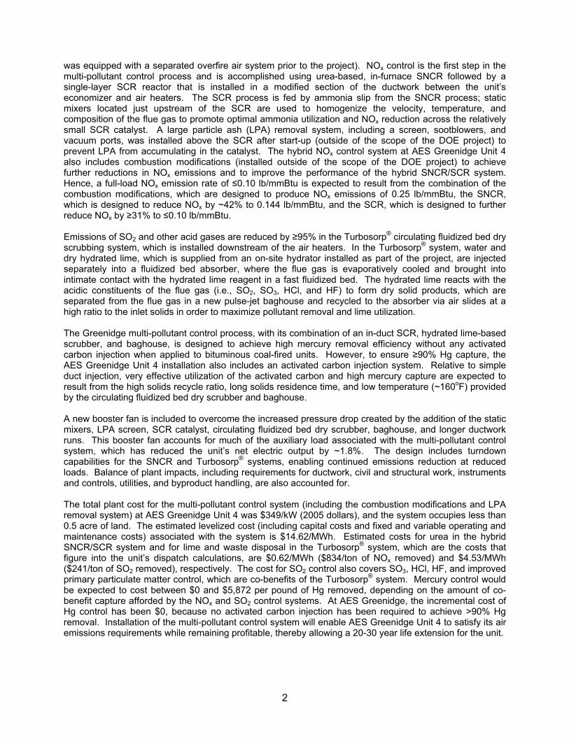
3.1.1 NOx Control NOx control is the first step in the multi-pollutant control process and is accomplished using urea-based, in-furnace selective non-catalytic reduction followed by a single-layer, in-duct selective catalytic reduction reactor that is fed by ammonia (NH3) slip from the SNCR process. Although not an essential component of the multi-pollutant control process, for certain
8

applications, such as that on AES Greenidge Unit 4, it may be advantageous to complement the hybrid SNCR/SCR system with combustion modifications designed to achieve further reductions in NOx emissions and to improve the performance of the hybrid SNCR/SCR system. In the SNCR process, aqueous urea (CO(NH2)2) is atomized and injected into the furnace above the combustion zone. The relatively high temperatures in the furnace promote dissociation of the urea into reactive radicals (e.g., NH2, NCO), which react with nitrogen oxide and oxygen to form molecular nitrogen, carbon dioxide, and water, according to the following overall reaction: CO(NH2)2 + 2 NO + ½ O2 → 2 N2 + CO2 + 2 H2O (1) The performance of a urea-based SNCR system can be quantified by computing its urea utilization, which is defined as:
Urea Utilization (%) = [NOx Reduction (%)] ÷ NSR, (2) where NSR is the normalized stoichiometric ratio, computed as: NSR = 2 · [moles urea] ÷ [moles inlet NOx] (3) Hence, if the system achieves a NOx reduction that is stoichiometrically equivalent to the amount of urea injected, then the urea utilization is 100%. If the NOx removal is less than stoichiometrically equivalent to the amount of urea injected, then the urea utilization is correspondingly less than 100%. In practice, urea utilization by SNCR systems is typically much less than 100% (e.g., 30 – 60 %, Albanese et al., 2005), in part because of restrictions on the amount of allowable ammonia slip from these systems. NOx reduction according to reaction (1) occurs over a temperature range of approximately 1400oF to 2200oF; however, the reaction is temperature-sensitive within this range, as illustrated in Figure 4. Ammonia is a byproduct of urea-based SNCR; the amount of ammonia produced by the process decreases as temperature increases. Because the amount of allowable NH3 slip is generally limited to 2-10 ppmv or less for coal-fired EGU applications, conventional stand-alone SNCR installations are typically designed to operate at relatively high temperatures that produce low amounts of ammonia slip. At these high temperatures, though, SNCR performance is adversely affected by competing reactions that consume the urea reagent or oxidize the reagent to form additional NOx, resulting in less-than-optimal urea utilization. In a hybrid SNCR/SCR system, greater levels of ammonia slip from the SNCR process are actually desirable, as the ammonia produced via SNCR serves as the reagent to effectuate additional NOx removal in the downstream SCR reactor. As a result, the SNCR system in a hybrid process can be designed to operate at lower temperatures (e.g., 1650-1900oF) than a stand-alone SNCR system would, resulting in improved urea utilization and greater NOx removal by the SNCR system, as well as sufficient NH3 slip to permit additional NOx reduction via SCR. Lower-temperature urea injection is accomplished in the hybrid SNCR/SCR system by including some injectors in upper sections of the furnace and in the convective pass.
9
1300 1500 1700 1900 2100 2300
Temperature (oF)
NOx Removal / Urea Injected Ammonia Slip
SNCRSNCR/SCR
1300 1500 1700 1900 2100 2300
Temperature (oF)
NOx Removal / Urea Injected Ammonia Slip
SNCRSNCR/SCR
Figure 4. Conceptual depiction of the effect of temperature on urea utilization and ammonia slip in SNCR, and the implications of this effect for hybrid SNCR/SCR design.
The flue gas exiting the furnace, which contains unreacted NOx (primarily NO) and NH3 produced by the SNCR process, next flows through a compact SCR reactor containing a single catalyst layer that is installed in a modified section of the ductwork between the unit’s economizer and air heater. The single-layer, in-duct SCR operates with the same process chemistry as a standard full-size SCR. Nitrogen oxides in the flue gas are reduced by ammonia (or by isocyanic acid, HNCO, which is also formed as part of the SNCR process) in the presence of a catalyst to form molecular nitrogen and water according to the following reactions:
4 NO + 4 NH3 + O2 → 4 N2 + 6 H2O (4) NO + NO2 + 2 NH3 → 2 N2 + 3 H2O (5) 4 NO + 4 HNCO + O2 → 4 N2 + 4 CO2 + 2 H2O (6)
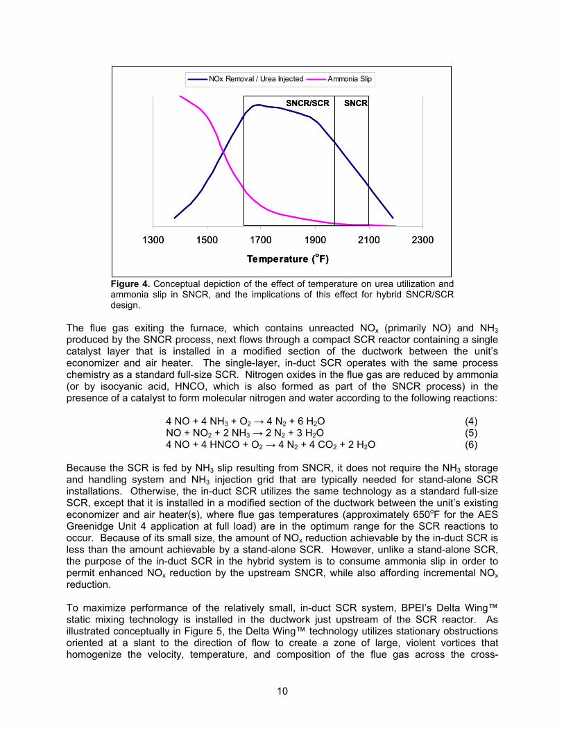
Because the SCR is fed by NH3 slip resulting from SNCR, it does not require the NH3 storage and handling system and NH3 injection grid that are typically needed for stand-alone SCR installations. Otherwise, the in-duct SCR utilizes the same technology as a standard full-size SCR, except that it is installed in a modified section of the ductwork between the unit’s existing economizer and air heater(s), where flue gas temperatures (approximately 650oF for the AES Greenidge Unit 4 application at full load) are in the optimum range for the SCR reactions to occur. Because of its small size, the amount of NOx reduction achievable by the in-duct SCR is less than the amount achievable by a stand-alone SCR. However, unlike a stand-alone SCR, the purpose of the in-duct SCR in the hybrid system is to consume ammonia slip in order to permit enhanced NOx reduction by the upstream SNCR, while also affording incremental NOx reduction. To maximize performance of the relatively small, in-duct SCR system, BPEI’s Delta Wing™ static mixing technology is installed in the ductwork just upstream of the SCR reactor. As illustrated conceptually in Figure 5, the Delta Wing™ technology utilizes stationary obstructions oriented at a slant to the direction of flow to create a zone of large, violent vortices that homogenize the velocity, temperature, and composition of the flue gas across the cross-
10
sectional area of the duct. For the in-duct SCR reactor, homogeneity in the distribution of NOx and NH3 throughout the flue gas is desired to maximize the utilization of the available catalyst surface, thereby maximizing NOx reduction and minimizing NH3 slip. In addition, the static mixers are designed to maintain ash entrainment and distribution across the cross-sectional area of the reactor, minimizing catalyst deactivation and pressure drop via fly ash plugging. For units such as AES Greenidge Unit 4 that produce large particle ash, a screen and/or other LPA removal equipment is also required upstream of the SCR reactor in order to prevent LPA from accumulating in the catalyst. Major process components for the hybrid SNCR/SCR system include urea storage equipment, urea delivery, metering, and distribution equipment, urea injection equipment, static mixers, LPA removal equipment (if required), SCR catalyst, duct modifications and catalyst support, and miscellaneous process control equipment. In addition, sonic horns and/or rake soot blowers are used to prevent ash buildup on top of the SCR catalyst. For the AES Greenidge Unit 4 installation, flue gas bypasses are not required around the economizer or the SCR catalyst, simplifying the design and operation of the system.
Static Mixer Vortex Circulation
Flue Gas
Static Mixer Vortex CirculationVortex Circulation
Flue Gas
Figure 5. Conceptual illustration of the Delta Wing™ static mixing technology.
3.1.2 SO2, SO3, HCl, HF, and Particulate Matter Control After exiting the SCR reactor and passing through the plant’s existing air heater(s), the flue gas is sent to the Turbosorp® circulating fluidized bed dry scrubbing system for removal of SO2, SO3, HCl, HF, and particulate matter. In the Turbosorp® system, the flue gas first enters the absorber vessel through a venturi nozzle. (The inlet to the absorber vessel may contain either a single venturi nozzle or multiple venturi nozzles, depending upon the volume of flue gas being treated). Water and hydrated lime (Ca(OH)2) are separately injected into the absorber above the venturi section. In the absorber vessel, the pollutant-laden flue gas is cooled in a fast fluidized bed of moistened particles, which include the injected hydrated lime as well as fly ash and reaction products. As the flue gas passes through the bed of particles, intimate contact is provided between the alkaline particles of hydrated lime and the acid gases contained in the flue gas. The surface moisture of these lime particles provides for liquid phase diffusion of the acid gases and contact
11

with the lime in solution. This is a quick absorption mechanism and the one mainly responsible for neutralization of the acid gases. The large surface area of the particles in the bed also provides for rapid heat transfer. Thus, the particles are quickly dried as the flue gas passes through the bed, and the flue gas is evaporatively cooled to within 45oF of its adiabatic saturation temperature. The acid gas constituents of the flue gas (SO2, SO3, HCl, HF, and to a lesser extent, CO2) are removed by reaction with hydrated lime. Each of these acid gas constituents produces a calcium-based salt and excess water when contacted with the alkaline Ca(OH)2 reagent. Sulfur dioxide and trioxide form calcium sulfite and sulfate hydrates. The halides, HF and HCl, form calcium fluoride and chloride, respectively. Some CO2 reacts to form calcium carbonate. These reactions are summarized below:
Ca(OH)2 + SO2 ↔ CaSO3 · ½ H2O + ½ H2O (7) Ca(OH)2 + SO3 ↔ CaSO4 · ½ H2O + ½ H2O (8) CaSO3 · ½ H2O + ½ O2 ↔ CaSO4 · ½ H2O (9) Ca(OH)2 + 2 HCl ↔ CaCl2 + 2 H2O (10) Ca(OH)2 + 2 HF ↔ CaF2 + 2 H2O (11) Ca(OH)2 + CO2 ↔ CaCO3 + H2O (12)
After exiting the absorber vessel, the dry, solid products (i.e., fly ash, unreacted hydrated lime, CaSO3, CaSO4, CaCO3, CaCl2, and CaF2) are separated from the flue gas in a baghouse, which is an integral part of the Turbosorp® system. (Although water is injected into the absorber vessel and formed by the reactions in the absorber, the flue gas remains unsaturated). To maximize acid gas removal and reagent utilization, most (e.g., ≥95%) of these solids are recycled via gravity to the absorber vessel using air slides. Upon reentering the absorber, the sulfite-coated surfaces of partially reacted Ca(OH)2 particles are moistened, causing the calcium sulfite to form needle-like crystals. This crystallization exposes fresh Ca(OH)2 surface, permitting additional reaction with acid gases and hence greater reagent utilization. Recycle of the baghouse solids provides ample residence time for sorbent reactivation and reaction with Ca(OH)2 according to this mechanism. In addition to removing the acid gas constituents of the flue gas, the circulating fluidized bed dry scrubbing system enhances removal of particulate matter. For plants such as AES Greenidge Unit 4 that are currently equipped with an ESP, installation of a baghouse is expected to improve fine particulate matter (PM2.5) capture efficiency. Moreover, the fluidized particle bed in the absorber vessel promotes particle agglomeration via collisions among particles, resulting in larger particles that can be captured more easily in the baghouse. Agglomeration is further enhanced by the water that is injected for flue gas humidification, which tends to increase the cohesion of the particles. Major components of the Turbosorp® system include the absorber vessel, hydrated lime storage and injection system, water storage and injection system, baghouse, solid product recycle and disposal system, and miscellaneous process control equipment. An onsite lime hydrator can be included as part of the installation to produce the required hydrated lime reagent from pebble lime, or the hydrated lime can be delivered to the site for direct use in the process. In addition, as shown in Figure 3, a flue gas recycle system may be included to provide sufficient flue gas flow to maintain a fluidized bed in the absorber at low load operation. Figure 6 presents a schematic of the Turbosorp® system highlighting the flow of solids, liquids, and gases through the process.
12

Hydrated Lime
Water
Flue GasTo Disposal
To StackHydrated Lime
Water
Flue GasTo Disposal
To Stack
Figure 6. Schematic of the Turbosorp® circulating fluidized bed dry scrubbing system. Red, blue, and green arrows indicate the paths of solids, liquids, and gases, respectively, through the system.
The process is totally "dry", meaning that it introduces the reagent as a dry, free-flowing powder and produces a dry, free-flowing disposal product. The absorber operates not only as a chemical reactor but also as an evaporative cooler. Surface humidity of particles within the fluidized bed is held nearly constant by introducing the water independently from the recirculated solids and fresh hydrated lime. This reduces the potential for scaling relative to wet and semi-dry processes. Water injection, reagent injection, and bed recirculation are independent unit operations. Thus, the process allows reagent injection rates that are a function of pollutant loading and emission targets.
3.1.3 Mercury Control Mercury control in the multi-pollutant control system being demonstrated at AES Greenidge is accomplished via the co-benefits afforded by the in-duct SCR, circulating fluidized bed dry scrubber, and baghouse and, if required, by the injection of activated carbon just upstream of the scrubber. From a mercury control perspective, the Greenidge multi-pollutant control process is very similar to a conventional air pollution control configuration comprising an SCR, spray dryer, and baghouse. Measurements have demonstrated that this configuration, when applied to plants firing bituminous coal, achieves a high level of mercury removal (i.e., 89-99%) without the need for any mercury-specific control technology (Withum, 2006; Miller et al., 2006). This high level of removal likely results from a combination of factors, including the conversion of elemental mercury (Hg0) to oxidized mercury (Hg2+) across the SCR catalyst (Presto and Granite, 2006), the removal of Hg2+ (a Lewis acid) via chemisorption by moistened, basic Ca(OH)2 particles in the scrubber (Lancia et al., 1993; Ghorishi and Gullett, 1998), and the removal of Hg2+ and possibly some Hg0 via adsorption onto carbon-containing fly ash and Ca(OH)2 at low
13

temperatures in the baghouse (CEA, 2005), which facilitates contact between gaseous mercury and carbon or other sorbent contained in the “dust cake” that accumulates on its numerous filter bags. The Greenidge multi-pollutant control process includes all of these components, and hence, it is likely that its combination of an in-duct SCR, Ca(OH)2-based scrubber, and baghouse will result in high mercury removals without any activated carbon injection when applied to bituminous coal-fired units. It is uncertain, however, whether Hg0 will be oxidized effectively across the SCR catalyst at the abnormally high space velocities resulting from the single-layer, in-duct design. Determining the extent of Hg oxidation and its effect on overall Hg removal is one of the objectives of the demonstration program. To ensure high mercury removal efficiencies, the multi-pollutant control system also includes an activated carbon injection system. Activated carbon, which adsorbs both Hg0 and Hg2+ (CEA, 2005), is injected into the flue gas just upstream of the Turbosorp® absorber vessel. Very effective utilization of the activated carbon and high mercury capture are expected to result from the long solids residence time provided by the circulating fluidized bed scrubbing system’s high solids recycle ratio. The relatively low temperatures (~160oF) in the Turbosorp® system and the thorough contact facilitated by caking of the carbon sorbent on the baghouse filter bags are also expected to result in a high capacity for mercury capture by the activated carbon, as compared to simple duct injection. Moreover, the Turbosorp® system may help to promote mercury capture by removing SO3, which has been shown to compete with Hg for active binding sites on the activated carbon particles (Presto and Granite, 2007). The activated carbon injection system includes a carbon storage silo, carbon feed and injection system, and miscellaneous process control instrumentation. The baghouse is used to remove spent carbon from the flue gas.
3.2 Design Objectives As discussed in the Introduction, the multi-pollutant control system being demonstrated at AES Greenidge was designed with the overall goal of providing an integrated process that is well suited for reducing emissions of a number of pollutants from smaller (i.e., 50-300 MWe) coal-fired EGUs. Therefore, the design responded to a number of objectives that are consistent with the needs of these smaller units. These objectives, which are synonymous with the advantages of the multi-pollutant control system over technologies that have conventionally been applied to smaller coal-fired units, are identified and discussed in the subsections below.
3.2.1 Deep Emission Reductions Conventional low-capital-cost air pollution control options for smaller coal-fired units, such as low-NOx burners or stand-alone SNCR to reduce NOx emissions and combustion of low-sulfur coal or use of sorbent injection in the furnace or ductwork to limit SO2 emissions, in most cases do not produce emission rates consistent with the low levels established in environmental regulations that recently have been promulgated or proposed. Hence, units employing these options are increasingly vulnerable to volatile allowance costs or even retirement as new regulations are enacted. Thus, it was essential that the Greenidge multi-pollutant control process be designed to achieve deeper emissions reductions than these conventional low-capital-cost options and to meet or exceed applicable state and federal regulatory requirements for air emissions.
14

The process being demonstrated at AES Greenidge is well suited for achieving NOx emission reductions of about 50-75%, compared with the 20-35% reduction typically achievable by SNCR (Pfaff and Abrams, 2006). It also is designed to achieve greater than 95% removal of SO2, comparable to the 95-98% removals characteristic of today’s best available wet scrubbing technologies for larger coal-fired units (DePriest and Gaikkwad, 2003). Furthermore, the multi-pollutant control system is designed to achieve greater than 90% capture of mercury, meeting or exceeding the performance of state-of-the art mercury control technologies, and to reduce emissions of SO3, HCl, and HF by at least 95%. NOx, SO2, and mercury are the focus of many state and federal environmental actions. SO3, HCl, and HF contribute to the formation of acid aerosols, and emissions of these compounds must be reported to the U.S. Environmental Protection Agency (EPA) as part of the national Toxics Release Inventory (TRI) program. Elevated concentrations of SO3 in flue gas can also result in the formation of visible emissions (i.e., “blue plumes”), which are often particularly problematic for coal-fired power plants with SCR systems because SO3 can be generated by oxidation of SO2 across the SCR catalyst. Although the Greenidge multi-pollutant control process includes an SCR reactor, the downstream circulating fluidized bed dry scrubber is designed for deep SO3 removal, eliminating the potential for plume visibility problems due to SO3. Finally, as discussed above, for plants currently using an ESP to control particulate matter emissions, installation of the circulating fluidized bed dry scrubber and baghouse is expected to afford a substantial improvement in PM control, especially for fine particles.
3.2.2 Low Capital Costs There are commercially-available conventional technologies, such as full-scale SCR systems and limestone forced oxidation wet scrubbers, that are capable of achieving or exceeding the deep emissions reductions targeted for the Greenidge multi-pollutant control process. However, operators of smaller coal-fired EGUs, which are penalized by economies of scale, often cannot afford the large capital costs associated with these technologies. Hence, the multi-pollutant control process being demonstrated at AES Greenidge was designed to achieve deep emission reductions while offering substantially reduced capital costs compared to these conventional state-of-the-art technologies. By using a compact, single-layer SCR reactor that is installed in a modified section of ductwork between the unit’s economizer and air heater, the hybrid SNCR/SCR system avoids many of the capital costs associated with the multi-layer reactor, structural support steel, foundations, and new ductwork runs required for a conventional stand-alone SCR system. Also, unlike wet FGD systems, the Turbosorp® system does not produce saturated flue gas, and therefore is constructed from carbon steel rather than from the expensive corrosion-resistant materials required for wet scrubbers. For the same reason, use of the Turbosorp® system also does not entail the installation of a new corrosion-resistant stack (or flue gas reheat system), which is commonly required for wet scrubber retrofits. Because of these factors, as well as the mechanical simplicity of the Turbosorp® system relative to wet scrubbers, the capital cost of the multi-pollutant control system installed at the 107-MWe AES Greenidge Unit 4 is estimated to be about 40% less than the capital cost would have been to retrofit the unit with a conventional system comprising a stand-alone SCR and wet limestone forced oxidation scrubber. In exchange for its substantially reduced capital costs, the Greenidge multi-pollutant control system has higher variable operating costs (because of its lower reagent utilization and its use of more expensive urea and lime reagents rather than the ammonia and limestone reagents
15
commonly used in stand-alone SCR and wet scrubber systems, respectively) and lower NOx removal efficiency (SCRs are capable of achieving 80-90% or greater NOx reduction) relative to a conventional stand-alone SCR / wet FGD system. Whereas this tradeoff may be unattractive for large coal-fired EGUs, it is consistent with the needs of smaller units, which in many cases cannot justify or afford the large capital costs (per unit of electrical output) needed to retrofit with conventional technologies for deep emissions reductions.
3.2.3 Small Space Requirements The relatively large amount of space required to install conventional SCR and wet FGD systems further prevents these technologies from being widely applied to smaller coal-fired EGUs. Many smaller coal-fired units do not have sufficient physical space to easily accommodate both an SCR and wet scrubber; this increases the difficulty, and hence the capital cost, of retrofitting these technologies. Therefore, an objective in designing the Greenidge multi-pollutant control system was to minimize its required footprint. The SNCR portion of the multi-pollutant control process requires only a small amount of space for a urea storage tank, a small shed containing the urea circulation module, and several small urea distribution skids located around the boiler. Unlike a conventional stand-alone SCR reactor, the single-layer SCR reactor requires essentially no new land area, as it is installed in a modified ductwork section between the economizer and air heater and needs only a few new support beams. The arrangement of the circulating fluidized bed dry scrubber, baghouse, and associated equipment is also compact. The various pieces of equipment are vertically tiered to permit gravity-assisted transport of solids where possible, and as a result, require less than 0.5 acre of land for a 110 MWe installation. The layout of the multi-pollutant control system for the Greenidge Unit 4 installation is discussed in greater detail in Section 4.3.2 of this report.
3.2.4 Applicability to High-Sulfur Coals As discussed in the Introduction, greater than 80% of the coal-fired units that are candidates for the multi-pollutant control process being demonstrated at AES Greenidge are located east of the Mississippi River, where high-sulfur eastern U.S. bituminous coal is a candidate fuel source. The dispatch economics of these units can improve significantly with the installation of low-cost SO2 removal systems that allow the use of higher-Btu, higher-sulfur, less-expensive coals with a net reduction in SO2 emissions and a corresponding reduction in the need for high-cost allowances. Hence, an important design objective for the Greenidge multi-pollutant control system was that it be able to achieve deep SO2 emission reductions when applied to units firing high-sulfur (i.e., >2%-sulfur) coals. Lime spray dryers provide a relatively low-capital-cost means for achieving deep reductions in SO2 emissions, as does the Turbosorp® circulating fluidized bed dry scrubber that was installed as part of the multi-pollutant control process at AES Greenidge. However, it is more difficult to treat high-sulfur flue gases and to achieve very high SO2 removal efficiencies with a spray dryer than with a circulating fluidized bed dry scrubber. In spray dryer systems, lime and water are injected into the absorber vessel together as a slurry, rather than separately as in the Turbosorp® system. As a result, increasing the lime injection rate (i.e., to accommodate a higher inlet SO2 loading or to increase the SO2 removal efficiency) may require a corresponding increase in the water injection rate to maintain the solids content of the slurry within acceptable
16

limits. For sufficiently high SO2 loadings and removal efficiencies, the slurry injection scheme imposes a limit on the amount of lime that can be injected, because excess water could lead to scaling in the absorber vessel, plugging and binding of baghouse bags, and plugging of discharge feeders and conveyers. As a result, spray dryer installations are typically limited to applications that require 95% or lower SO2 removal efficiency and to units that fire coals with sulfur contents of about 2% (~3 lb SO2 / mmBtu) or less. As discussed in Section 3.1.2 above, in the Turbosorp® system, water injection and hydrated lime injection are carried out separately, such that the Ca(OH)2 injection rate is controlled solely by the pollutant loading and desired emission reduction, without being limited by the temperature or moisture content of the flue gas. As a result, the Turbosorp® system can be operated to achieve deep emission reductions (i.e., 98% or greater) for a wide range of fuels, including high-sulfur coals (i.e., up to 5 lb SO2 / mmBtu or more).
3.2.5 Low Maintenance Requirements Insofar as the PPII seeks to improve the reliability of the nation’s energy supply, minimization of maintenance requirements was an objective in the design of the Greenidge multi-pollutant control system, such that system maintenance will not adversely affect unit availability. A drawback of both wet scrubbers and lime spray dryers is their use of slurries to introduce the limestone or lime into the system, resulting in high maintenance requirements and potential for operational problems. Problems arising from the use of slurries can include pipe plugging, nozzle plugging, solids build-up, and erosion and abrasion of pumps, pipes, and vessels. Wet scrubbers in particular are relatively complex, as they produce a slurry product and require pumps for slurry recirculation as well as maintenance-intensive dewatering equipment. The Turbosorp® circulating fluidized bed dry scrubber that was installed as part of the Greenidge multi-pollutant control system is expected to afford substantially reduced maintenance requirements compared to these more conventional FGD technologies. In the Turbosorp® process, lime is injected into the absorber as a dry hydrate rather than as a slurry. A blower is used to pneumatically convey the dry hydrated lime to the absorber for injection. The solids collected in the baghouse are also completely dry and are recycled to the absorber using airslides. Gravity provides the motive force for injection via the differential height between the bottom of the baghouse and the injection point on the absorber tower. Apart from the lime hydration system (if included), the system’s only pump is used to inject liquid water into the absorber vessel. Hence, the process avoids the problems with plugging, erosion, abrasion, and scaling that can result from pumping and handling slurries in other types of scrubbing systems. The Turbosorp® system also includes comparatively few moving parts, and as implied in Section 3.2.4, is less likely to cause plugging and binding of fabric filter bags than a spray dryer is.
3.2.6 Operational Flexibility Unlike larger baseload units, many smaller coal-fired EGUs routinely cycle their loads in response to electricity demand. Hence, a multi-pollutant control system designed for these smaller units should feature turndown capabilities to permit continued emissions reductions at reduced operating loads. The design of the multi-pollutant control system being demonstrated at AES Greenidge includes these capabilities.
17

For conventional SCR systems, low-load operation is constrained by reduced flue gas temperatures, which can cause incomplete ammonia consumption across the SCR catalyst, resulting in high ammonia slip and ammonium bisulfate fouling in the air heater (see Section 3.3.1). At sufficiently low temperatures, catalyst plugging and deactivation can also occur via the formation of salts in the SCR reactor. These constraints are particularly stringent for units that fire high-sulfur coals. Stand-alone SCR installations typically employ an economizer gas bypass and/or water flow circuit modifications to raise the flue gas temperature at the SCR inlet during low-load operation. However, because of the hybrid NOx control strategy included as part of the Greenidge multi-pollutant control process, NOx removal capabilities are available to some extent at lower operating loads without the need for any such modifications. The operating strategy for the hybrid system is shown conceptually in Figure 7.
Generator Load (MW)
NO
x at
Sta
ck (l
b/m
mBt
u)
Low-NOx Burners
SNCR
SCR
Min
imum
SC
R O
pera
ting
Tem
pera
ture
Min
imum
SN
CR
Ope
ratin
g Te
mpe
ratu
re
Minimum Load
Maximum LoadGenerator Load (MW)
NO
x at
Sta
ck (l
b/m
mBt
u)
Low-NOx Burners
SNCR
SCR
Minimum Load
Maximum Load
Min
imum
SC
R O
pera
ting
Tem
pera
ture
Min
imum
SN
CR
Ope
ratin
g Te
mpe
ratu
re
Figure 7. Operating strategy for the hybrid NOx control system being demonstrated at AES Greenidge.
As illustrated in the figure, operation of the system varies with generator load, resulting in three distinct operating ranges: a high-load range in which NOx reduction is accomplished via SCR, SNCR, and low-NOx burners (if applicable); an intermediate-load range in which NOx reduction is accomplished via SNCR and low-NOx burners (but not SCR), and a low-load range in which NOx reduction is accomplished via low-NOx burners (but not SCR or SNCR). At generator loads that produce economizer outlet temperatures below the minimum operating temperature for the SCR reactor, urea injection into the upper (cooler) region of the furnace, which is used to generate ammonia slip for the SCR, is discontinued. However, the lower zones of urea injection continue to operate until the minimum SNCR operating temperature is reached, resulting in continued NOx removal via SNCR. Below the minimum SNCR operating temperature, which is the minimum economizer outlet temperature at which it is safe to introduce very small amounts of ammonia into the SCR catalyst, urea injection into the furnace is discontinued. However, NOx emissions may continue to be controlled via the unit’s low-NOx combustion system, if applicable. Hence, for smaller units that regularly cycle loads based upon peak and off-peak demands, the load following capabilities of the hybrid SNCR/SCR process can help to contribute to lower NOx emission averages.
18

The circulating fluidized bed dry scrubber is also capable of operating at reduced loads. As discussed in Section 3.1.2, depending upon the extent of turndown that is desired, a flue gas recycle system may be required to provide sufficient flow to the absorber so that a fluidized bed can be maintained at the low end of the operating range.
3.3 Design Considerations In addition to the larger design objectives discussed above and the obvious objectives established by the particular emission reduction needs of a candidate unit, a number of site- and application-specific factors affect the design of the multi-pollutant control process that is being demonstrated at AES Greenidge Unit 4. Important design considerations for the process are discussed in the following subsections.
3.3.1 Coal and Ash Characteristics Characteristics of a candidate unit’s coal (and other secondary fuels if applicable) and the fly ash produced by its combustion impact the design of many aspects of the multi-pollutant control system. Certain elemental chemical components of the coal, including arsenic and alkali metals, can poison the SCR catalyst by reacting with its active sites, causing deactivation (Wu, 2002). For an in-duct SCR reactor, which includes a limited catalyst volume, catalyst deactivation can have an appreciable impact on NOx removal performance. Coal sulfur content can also affect the operation of the hybrid NOx control system. As mentioned in Section 3.2.1, the SCR catalyst promotes oxidation of a small percentage of SO2 in the flue gas to SO3, according to the following reaction:
SO2 + ½ O2 → SO3 (13)
This SO3 can then react with Ca to form CaSO4, which deactivates the catalyst by plugging its pores, or it can react with NH3 at sufficiently low temperatures to form NH4HSO4 or (NH4)2SO4 according to the reactions below, causing catalyst plugging or air heater fouling.
SO3 + NH3 + H2O → NH4HSO4 (14) NH3 + NH4HSO4 → (NH4)2SO4 (15)
Hence, for mid- and high-sulfur coals, the SO2-to-SO3 conversion rate is an important consideration in the selection of an SCR catalyst. The fly ash content of the flue gas must also be considered as part of the SCR system design, because greater ash loadings augment the potential for fly ash plugging, which causes catalyst deactivation and increased pressure drop. Thus, specification of a rake soot blower, sonic horn system, or other catalyst cleaning system is important to prevent deteriorations in SCR performance resulting from accumulation of fly ash in the catalyst.
19

For the circulating fluidized bed dry scrubbing system, the coal sulfur content affects the amount of hydrated lime reagent required per mole of inlet SO2 (i.e., the required Ca/S molar ratio) to achieve a given level of SO2 removal. Although the Turbosorp® circulating fluidized bed dry scrubber is capable of achieving deep SO2 emissions reductions across a wide range of coal sulfur contents, higher sulfur coals generally require greater Ca/S molar ratios than do lower sulfur coals for a given percentage of SO2 removal. Coal chlorine content also affects the performance of the circulating fluidized bed dry scrubber. CaCl2 is deliquescent. Hence, as the chlorine content increases, the process must be operated further from the adiabatic saturation temperature in order to avoid caking in the absorber vessel and plugging in the downstream equipment. Finally, the composition of the coal and fly ash can affect the mercury removal performance of the system. For example, as coal chlorine content increases, the percentage of mercury in the flue gas that is present as Hg2+ (e.g., HgCl2) as opposed to Hg0 increases (CEA, 2005). Greater Hg2+ concentrations improve the potential for mercury removal as a co-benefit of the circulating fluidized bed dry scrubber and baghouse. This potential also increases as the amount of unburned carbon in the fly ash increases, because unburned carbon can adsorb gaseous mercury, especially at the low temperatures (Fenger and Winschel, 2006) afforded by the circulating fluidized bed dry scrubber, and can also serve as a mercury oxidation catalyst in the presence of sufficiently high chlorine concentrations (Niksa and Fujiwara, 2005; Presto and Granite, 2006). Hence, coal and ash characteristics may play a role in determining whether activated carbon injection is required for Hg control and, if so, what injection rate is needed.
3.3.2 Baseline NO Concentration The kinetics for NOx reduction via SNCR are a function of the initial concentration of NO, one of the reactants in the process and one of the products of the high-temperature reactions involving oxidation of reagent to form NO. Hence, the amount of NOx removal achievable in the SNCR process depends on the concentration of NO leaving the combustion system. Baseline NO concentrations vary considerably from unit-to-unit, as they are a function of factors such as fuel nitrogen content, fuel volatile matter content, flame temperature, and combustion zone stoichiometry and residence time.
3.3.3 Temperature Profile in the Furnace As discussed in Section 3.1.1, the performance of SNCR depends strongly on the temperature at which the process operates. Hence, the temperature profile in the furnace, which is specific to each application, strongly influences the design of the urea injection strategy. Computational fluid dynamics (CFD) are used to model the furnace temperature profile at various loads, and chemical kinetic modeling (CKM) is used to simulate the effect of temperature on the SNCR reactions. Modeling results form the basis for the design of the number, type, and placement of the urea injectors, as well as the urea injection strategy as a function of operating load.
3.3.4 Flue Gas Residence Time and Flow Profile in the Furnace In order to optimize SNCR performance, a urea injection strategy must be developed that provides for thorough mixing of the reagent with the flue gas and sufficient residence time of
20

urea and flue gas in the temperature regions of the furnace where the desired reactions between urea and NO occur. Reagent distribution and residence time are affected by the flue gas flow profile in the furnace. As with temperature, CFD and CKM are used to model the flow profile in the furnace and its effect on the SNCR reactions, and the results are used to inform the design of the urea injection strategy.
3.3.5 CO Concentrations in the Furnace Carbon monoxide significantly impacts SNCR chemistry, with net effects of reducing ammonia slip, promoting the oxidation of reagent to form additional NO, and lowering the optimal temperature for NO reduction (Brouwer et al., 1996). Hence, local CO concentrations must be considered when modeling and designing the urea injection system.
3.3.6 Available Space Between the Economizer and Air Heater The amount of incremental NOx removal and ammonia slip control achievable by the SCR reactor is limited by the residence time of the flue gas in the catalyst. Residence time is the inverse of space velocity (flue gas volumetric flow rate ÷ catalyst volume), and for a given flue gas flow rate, it increases with increasing catalyst volume. For the in-duct SCR reactor that is part of the Greenidge multi-pollutant control system, the volume of catalyst that can be installed, and hence the level of NOx removal that can be achieved via SCR, is restricted by the amount of available space between the candidate unit’s economizer and air heater. For a given catalyst, oxidation of Hg, which is a desired co-benefit of SCR, and conversion of SO2 to SO3, which is undesired, are also expected to decrease with decreasing catalyst volume. The geometry between the economizer and air heater also affects the catalyst face velocities (flue gas volumetric flow rate ÷ catalyst cross-sectional area) that can be achieved. High and low face velocities can each present problems; high face velocities contribute to increased catalyst erosion, whereas low face velocities can lead to ash deposition within the catalyst. For the retrofit application of an in-duct SCR reactor, the reactor cross-sectional area is typically limited by unit geometry, resulting in face velocities that are greater than normal. The effects of these elevated face velocities must be considered as part of the catalyst and reactor designs.
3.3.7 Flue Gas Temperature at the Economizer Outlet Catalyst activity is a function of temperature, and within the acceptable temperature window for SCR operation, the rate of NOx removal increases as temperature increases. Hence, the catalyst specification and the amount of NOx removal achievable in the single-layer in-duct SCR reactor both depend on a unit’s economizer outlet temperature. Variations in this temperature with unit load are a primary factor in establishing the turndown ranges for the SCR and SNCR systems, as illustrated in Figure 7. Per the discussion in Section 3.2.6, an economizer bypass can be installed to increase the temperature of the flue gas entering the SCR at reduced operating loads, increasing its turndown capability; however, the potential benefits afforded by this option must be weighed against its resultant effects on cost and operating complexity, and it was not selected for this project.
21

3.3.8 Flue Gas Homogeneity at the SCR Inlet As discussed in Section 3.1.1, in order to maximize performance of the relatively small in-duct SCR reactor, it is essential that the temperature, composition, and velocity of the flue gas are homogeneous across the cross-sectional area of the catalyst. Localized deviations in composition (i.e., NH3/NOx mole ratio) or temperature from target values can result in decreased NOx removal efficiency and increased ammonia slip, and localized deviations in velocity from target values can result in catalyst erosion or ash deposition. Hence, static mixers are used to homogenize the flue gas upstream of the in-duct SCR reactor. Because flue gas flows are unique to each candidate unit, physical flow modeling must be performed on a case-by-case basis to optimize the design of the static mixing system.
3.3.9 Large Particle Ash If the candidate unit produces large particle ash (even if only in small quantities), then this LPA must be removed from the flue gas upstream of the SCR reactor in order to prevent it from plugging the catalyst. Large particle ash, which consists of pieces of slag that in many cases are too large to pass through the catalyst, poses a potential problem for many conventional SCR installations. If it is not captured ahead of the SCR, the LPA can become lodged in the catalyst and promote subsequent accumulation and bridging of fly ash, eventually plugging a substantial portion of the catalyst. This in turn causes an increase in the pressure drop across the SCR reactor (potentially straining downstream fans and ductwork), as well as decreased NOx removal efficiency, increased ammonia slip, and increased catalyst erosion. In conventional installations, potential LPA problems are often easily mitigated by installing a screen and hopper at a 90° bend in the ductwork upstream of the SCR reactor. However, physical constraints associated with the in-duct SCR design that is employed by the hybrid SNCR/SCR system can make the installation of an LPA removal system more challenging. The design of the LPA removal system varies by unit and is dependent upon factors such as the amount of available space between the economizer and SCR reactor, the presence or absence of a 90º bend in the ductwork upstream of the reactor, the presence or absence of obstructions that could interfere with the screen, and the feasibility of utilizing hoppers to remove the captured LPA. The application at AES Greenidge Unit 4 was particularly challenging in that it involved vertical flow between the economizer and SCR, with obstructions (i.e., static mixers and an expansion joint), limited space, and no 90º bends or hoppers. This required the development of a unique LPA removal system, which is described in Section 4.2.2. When selecting an LPA screen, important considerations include the pitch (which affects both the LPA capture efficiency and the pressure drop) and the material of construction (which affects the durability of the screen). The catalyst pitch can also be increased to reduce the likelihood of LPA accumulation, although this reduces the NOx removal efficiency achievable by the SCR system.
3.3.10 Amount of Allowable Ammonia Slip In spite of its use of an in-duct SCR reactor to consume ammonia slip from the SNCR process, the design of the hybrid SNCR/SCR system is nevertheless constrained to some extent by ammonia slip. Obviously, the design level of ammonia slip from the SNCR process can be no greater than the sum of the amount of ammonia consumed in the SCR reactor and the amount of allowable ammonia slip from the overall hybrid system. As the SCR catalyst deactivates, its
22

capacity to consume ammonia decreases; hence, limits on ammonia slip constrain the useful operating life of the catalyst. Moreover, at operating loads below the minimum SCR operating load, limits on ammonia slip restrict SNCR operation, resulting in less-than-optimal urea utilization and NOx removal. Constraints on ammonia slip typically become more stringent as coal sulfur content increases, because the resultant greater concentrations of SO3 in the flue gas provide a greater driving force for the formation of ammonium bisulfate (NH4HSO4) from any ammonia that is present. For units firing lower-sulfur coals, constraints may be also imposed by regulatory limits on NH3 emissions or concerns about NH3 contamination of the baghouse solids, which makes disposal or use of these solids more difficult.
3.3.11 Approach to Adiabatic Saturation in the Absorber Vessel In addition to its dependence on the concentration of SO2 in the flue gas, the Ca/S molar ratio required to achieve a given level of SO2 removal in the circulating fluidized bed dry scrubber depends on the proximity of the temperature in the absorber vessel to the adiabatic saturation temperature of the flue gas. In general, for a given Ca(OH)2 injection rate, SO2 removal efficiencies improve as the operating temperature approaches the adiabatic saturation temperature. However, the approach to adiabatic saturation is limited by concerns about condensation, which can cause corrosion, deposition of solids in the absorber, binding and plugging of baghouse bags, and problems with the solids recirculation system. Hence, the absorber operating temperature must be carefully selected to maximize SO2 removal efficiency while avoiding any potential for condensation. Also, because the circulating fluidized bed dry scrubbing system operates at temperatures near the adiabatic saturation temperature of the flue gas, thorough insulation of the system is important, especially in colder climates, in order to minimize the potential for condensation. Per the discussion in Section 3.3.1, as the Cl content of the flue gas increases, the scrubber must be operated further from adiabatic saturation in order to avoid condensation. (The presence of Cl improves SO2 capture efficiency, however, approximately negating any effect of the higher operating temperature on the required Ca/S molar ratio).
3.3.12 Hydrated Lime Supply As discussed in Section 3.1.2, the multi-pollutant control system can be installed with or without a lime hydration system. Inclusion of a hydrator allows the plant to produce hydrated lime reagent onsite from purchased pebble lime. Otherwise, hydrated lime must be purchased for direct use in the process. On a mass basis, hydrated lime costs about 25% more (excluding delivery) and contains 24% less Ca than pebble lime. Hence, the cost per mole of Ca (excluding delivery) is about 65% greater for hydrated lime than for pebble lime, and the use of purchased hydrated lime substantially increases the multi-pollutant control system’s variable operating and maintenance (O&M) costs. Nevertheless, some operators may choose to purchase hydrated lime in order to avoid the capital investment and maintenance requirements associated with a lime hydration system. Even if a hydrator is included, the design should provide capability for accepting delivery of hydrated lime so that the hydrator can be taken offline for maintenance without affecting operation of the Turbosorp® scrubber.
23

3.3.13 Increased Solids Loading to the Baghouse Because a large portion of the solids that are removed from the flue gas in the baghouse are recycled back to the Turbosorp® absorber vessel, the particle loading in the flue gas that is sent to the baghouse from the absorber vessel is substantially greater than it would have been with no circulating fluidized bed dry scrubber installed. As a result, the baghouse must be designed to accommodate this increased particle loading. Design modifications may include reducing the air-to-cloth ratio (i.e., ft3/min flue gas ÷ ft2 bag surface area), increasing the bag spacing, and increasing the baghouse inlet volume and depth of the drop-out zone beneath the bags. The substantially increased particle loading resulting from solids recirculation is one reason why a unit’s existing particulate control device typically cannot be used for PM removal in a circulating fluidized bed dry scrubber installation. (The existing particulate control device can be retained ahead of the scrubber to capture fly ash separately from the solid scrubber products. This arrangement may be economically attractive if the fly ash can be sold; however, a second particulate control device would still be required as part of the circulating fluidized bed dry scrubber). Conceptually, a new ESP could be used instead of a new baghouse with the Turbosorp® system; however, baghouses are preferred because the coating of sorbent material that accumulates on their filter bags promotes additional removal of SO2, acid gases, and mercury downstream of the absorber vessel, improving reagent utilization and overall pollutant removal efficiency. Particle loading also affects the amount of compressed air required by the baghouse. A candidate unit’s compressed air capacity must be assessed and increased if necessary in order to ensure that it is sufficient to satisfy the baghouse demand.
3.3.14 Pressure Drop Across the System Addition of the static mixing devices, LPA screen (if included), in-duct SCR catalyst, fluidized bed absorber, baghouse, and longer ductwork runs causes increased flue gas pressure drop. Hence, most applications of systems like the Greenidge multi-pollutant control system will require installation of a booster fan and/or modifications to the unit’s existing ID fans to overcome this pressure drop. The amount of pressure drop and required modifications depend upon flue gas flow rate, equipment sizing and design, and existing ID fan capacity, and must be assessed on a case-by-case basis. The effect of increased pressure drop on the operating costs of the system must be considered as part of the design.
3.4 Project Uniqueness and Uncertainties All of the technologies being demonstrated as part of the Greenidge Multi-Pollutant Control Project have been developed and tested individually at a sufficient scale to provide an adequate level of confidence concerning their mechanical operability. However, the Greenidge Project is unique in that it represents the first application in which a hybrid SNCR/SCR system and a circulating fluidized bed dry scrubbing system have been combined to form an integrated multi-pollutant control system, as well as the first application of either of these technologies to a unit firing >2%-sulfur eastern U.S. bituminous coal.
24

The Turbosorp® circulating fluidized bed dry scrubber has been applied to four European coal-fired power plants but has not previously been demonstrated on a coal-fired EGU in the United States. Table 1 shows design targets for these European installations, as well as design capabilities for the Greenidge installation. As these data indicate, the Turbosorp® unit at AES Greenidge is designed for a greater flue gas SO2 concentration and greater level of SO2 removal than any existing installation. Circulating fluidized bed dry scrubbers similar to the Turbosorp® have been installed on two smaller coal-fired EGUs in the United States; however, both of these units fire less than 2%-sulfur coal and are less than 100 MWe in size. The hybrid SNCR/SCR system has been tested on the equivalent of 80 MWe of flue gas from the PSE&G Mercer Unit 2, which fired coal with a sulfur content of less than 1%. The SCR configuration involved horizontal flow through two 5-foot-thick banks of plate catalyst. Relative to operation using only SNCR, the hybrid SNCR/SCR system improved overall NOx reduction from 37% to 71% and overall urea utilization from 31% to 62% (for a constant urea feed rate) at full load, with less than 10 ppm of ammonia slip (Albanese et al., 1995). Hybrid SNCR/SCR was also demonstrated at commercial scale on the former 147 MWe GPU Generation Seward Unit 5, which fired bituminous coal containing about 1.5% sulfur. The system was designed to achieve 55% NOx reduction from a baseline of about 0.78 lb/mmBtu, with the in-duct SCR contributing about 6% reduction at full load. The demonstration confirmed the feasibility of the hybrid SNCR/SCR concept, but its performance was limited by temperature stratification in the SCR and arsenic poisoning of the catalyst (Urbas, 1999). Hence, the Greenidge demonstration marks the greatest targeted NOx removal efficiency for a commercial-scale hybrid SNCR/SCR system on a coal-fired boiler in the United States, as well as the first application of the hybrid system to a unit firing >2%-sulfur eastern U.S. bituminous coal. It also marks the first installation of the hybrid SNCR/SCR system on a coal-fired unit in which the flue gas flows vertically downward through the in-duct SCR catalyst with no upstream economizer hopper or ductwork bend to capture large ash particles. (The Seward installation had vertical, downward flow through the catalyst, but it included a 90º bend and an economizer hopper upstream of the reactor).
Table 1. Characteristics of existing Turbosorp® installations and of the AES Greenidge design.
Plant Country Coal Type Flue gasflow rate[m3/h]a
Approx. SO2
concentr.[mg/m3]b
SO2 removal
efficiency[%]
Approx. HCl
concentr. [mg/m3]b
HCl removal
efficiency[%]
Date of
start-up
Kraftwerk Zeltweg Austria lignite /
bituminous 600,000 2,300 91 100 > 90 1994
Kraftwerk St. Andrä Austria lignite /
bituminous 450,000 2,500 92 100 > 90 1994
Heiz-KW Strakonice
Czech Republic lignite 261,000 4,200 85 30 > 75 1999
REA Siekierki Poland bituminous 250,000 3,300 85 250 > 95 2002
AES Greenidge USA bituminous 450,000 5,000 95 100 > 95 2007
aAt standard temperature and pressure, wet; bAt standard temperature and pressure, dry Thus, the principal uncertainties, and the motivation for the Greenidge Multi-Pollutant Control Project, include the performance of the hybrid SNCR/SCR and Turbosorp® systems when combined in an integrated multi-pollutant control process, as well as the technical and economic
25

performance of these systems when applied with ambitious performance targets to a unit firing eastern U.S. bituminous coals containing greater than 2% sulfur. Specific uncertainties include: • Control and performance of the combined combustion modifications, SNCR, and in-duct
SCR, especially during load swings/cycling • Catalyst activity, life, and replacement cost for an in-duct single catalyst layer installed on a
unit firing greater than 2%-sulfur eastern U.S. bituminous coal • Extent of ash accumulation in the catalyst for an in-duct SCR reactor with vertical downward
flow and no upstream hoppers or ductwork bends • Effect of biomass co-firing on catalyst life and performance • Effect of ammonia slip from the hybrid SNCR/SCR on unit operability for a unit firing greater
than 2%-sulfur coal • Extent of Hg oxidation at high space velocities across the single catalyst layer and its effect
on Hg removal performance • SO2 capture and required Ca/S ratio in the Turbosorp® for a high-sulfur U.S. bituminous coal • Amount of Hg removal achievable in the Turbosorp® system and required activated carbon
injection rate • SO3, HCl, and HF removal as a function of SO2 control conditions • Effect of biomass co-firing on Hg and acid gas removal • Effects of ammonia slip and carbon injection on solid waste management • Economics of the combined system for a relatively small (~110 MWe) unit firing greater than
2%-sulfur eastern U.S. bituminous coal The goal of the Greenidge Project’s testing program is to resolve these uncertainties so that the technical and economic viability of the integrated multi-pollutant control process for smaller coal-fired units can be proven.
4. System Design for AES Greenidge Unit 4 Having discussed the general concepts, objectives, design considerations, and uncertainties associated with the multi-pollutant control process in the preceding section, this section focuses specifically on the system design for the AES Greenidge Unit 4 application. Process flow diagrams including mass and energy balance data for major process streams at design load (drawing No. 100276-SK081706-05) and at low load (drawing No. 100276-SK101206-03) are included in Appendix A. Appendix B presents a list of the major equipment items required for the system. Piping and instrument diagrams (P&IDs) for major process components are provided in Appendix C, and general arrangement drawings are provided in Appendix D. The design is described in the subsections below.
4.1 Design Basis As discussed in Section 2.2, the multi-pollutant control system at AES Greenidge Unit 4 is designed to operate effectively while the unit fires eastern U.S. bituminous coals containing 2-4% sulfur and co-fires waste wood at 0-10% of the heat input to the furnace. The design case is based on the use of a 2.9%-sulfur coal with approximately 10% biomass co-firing at the unit’s maximum continuous rating (MCR). Design fuel characteristics are summarized in Table 2.
26

The assumed chemical compositions of the quicklime and activated carbon reagents used by the process are summarized in the stream tables provided with the process flow diagrams in Appendix A. The NOxOUT® reagent used by the SNCR process is an aqueous solution containing approximately 50% (w/w) urea, as well as additives to prevent scaling and corrosion.
Table 2. Assumed fuel characteristics (as fired) for the design case. Coal Wood Blended Fuel
Higher Heating Value (Btu/lb) 13,097 8,592 12,426 Carbon (% w/w) 72.17 45.13 68.14 Hydrogen (% w/w) 4.79 5.78 4.94 Nitrogen (% w/w) 1.36 2.8 1.57 Chlorine (% w/w) 0.1 0.22 0.12 Sulfur (% w/w) 2.9 0.2 2.5 Oxygen (% w/w) 5.04 38.72 10.05 Moisture (% w/w) 5.8 6.3 5.87 Ash (% w/w) 7.85 0.82 6.8 Table 3 lists the emission performance targets for the design case. The targeted NOx emission rate of ≤0.10 lb/mmBtu at full load represents a NOx removal efficiency by the combined combustion modifications, SNCR, and in-duct SCR of ≥67% relative to a pre-installation baseline NOx emission rate of approximately 0.30 lb/mmBtu, or a removal efficiency by the hybrid SNCR/SCR system of ≥60% relative to the targeted rate of 0.25 lb/mmBtu leaving the new combustion system.
Table 3. Emission performance targets for the design case. Parameter Design Target NOx ≤ 0.10 lb/mmBtu (full load) NH3 ≤ 2 ppmvd @ 3% O2 (air heater inlet) SO2 ≥ 95% removal SO3 ≥ 95% removal HCl ≥ 95% removal HF ≥ 95% removal Hg ≥ 90% removal Opacity ≤ 20%
4.2 Description by Major Process Component Major components of the multi-pollutant control process being demonstrated at AES Greenidge Unit 4 include a selective non-catalytic reduction system, in-duct selective catalytic reduction reactor, activated carbon injection system, Turbosorp® scrubber, process water system, lime hydration and injection system, baghouse, ash recirculation system, and booster fan.
4.2.1 Selective Non-Catalytic Reduction System The urea-based SNCR system, which was supplied by Fuel Tech, is designed to operate synergistically with the in-duct SCR reactor to reduce NOx emissions from AES Greenidge Unit 4. At full load operation, the SNCR system is designed to reduce NOx by about 42%, from 0.25 lb/mmBtu (190 ppmvd, corrected to 3% O2) leaving the combustion zone to 0.144 lb/mmBtu (110 ppmvd, corrected to 3% O2) at the economizer outlet, and to supply a controlled amount of
27

ammonia slip (~47 ppmvd, corrected to 3% O2) as a feed to the downstream in-duct SCR reactor to permit additional NOx reduction there. Per the discussion in Section 3.2.6, for gross generator loads below about 86 MWe, which produce economizer outlet temperatures below the minimum SCR operating temperature of 600oF, the SNCR is designed to reduce NOx emissions by 20-25% while producing less than 2 ppmvd of ammonia slip. Because of concerns about formation of ammonium salts in the SCR catalyst, SNCR operation is discontinued when the economizer outlet temperature is less than 528oF, which occurs when the gross generator load falls below about 54 MWe. The SNCR system design includes three separate zones of urea injection into the boiler, as illustrated in drawing No. 575P-M01-02 in Appendix C. In Zones 1 and 2, diluted urea reagent is injected via air-cooled wall injectors that are installed through penetrations in the waterwall. The Zone 1 injectors, which are located closest to the combustion zone, are mounted on retract mechanisms that allow them to be withdrawn from the furnace when not in use, preventing damage that could otherwise result from high furnace temperatures. In Zone 3, diluted urea reagent is injected through two 14-15 ft, retractable multiple nozzle lances (MNLs) into the superheater section. The MNLs are cooled using plant condensate water. Because SNCR performance depends strongly on temperature and reagent distribution, as discussed in Sections 3.3.3 and 3.3.4, the optimal placement and spray patterns for injectors and lances were determined based on CFD and CKM results. Figure 8 provides an example of the CFD modeling results that were used in the design of the hybrid NOx control system for AES Greenidge Unit 4; both the temperature and velocity profiles (shown here for a case in which the unit is operating at 103% of its MCR) are utilized to inform the design of the urea injectors.
Figure 8. Example of CFD modeling results used in the design of the hybrid NOx control system for AES Greenidge Unit 4 (Boiler 6). Shown are temperature and velocity profiles for a case in which the unit is operating at 103% of its MCR.
28

The use of multiple urea injection zones is necessary to ensure thorough coverage of the reagent throughout the flue gas and to allow injection of urea into different temperature regions of the furnace, which is critical to the load-following capabilities of the hybrid SNCR/SCR system. At high load, when greater levels of ammonia slip are desired to feed the in-duct SCR reactor, urea can be injected into lower temperature regions of the furnace (i.e., by using the Zone 2 injectors and Zone 3 MNLs) that promote greater NOx removal via SNCR and greater ammonia slip. At reduced loads, however, when ammonia slip from the SNCR is limited to <2 ppmvd, urea injection is restricted to higher temperature regions of the furnace (i.e., by using only the Zone 1 or Zone 2 injectors). The liquid, urea-based NOxOUT® reagent used by the SNCR process is delivered to site via tank truck and stored in a 15,000-gallon, fiberglass reinforced plastic tank. The tank is heated and insulated to maintain its temperature above 80oF in order to prevent the urea from crystallizing and precipitating out of the solution, and it is installed on a curbed concrete foundation for spill containment. A high flow delivery and circulation (HFD) module is used to supply filtered urea-based reagent from the storage tank to the process. The HFD module includes two 100% capacity, 5-hp centrifugal pumps (Pump 1A and Pump 1B in drawing No. 100276-SK081706-05) to circulate the urea solution and provide it to the injector zone metering (IZM) module, the next step in the urea injection process. The HFD module is contained in a heated enclosure located next to the urea storage tank; all piping interconnecting the SNCR system components is heat traced and insulated to prevent urea crystallization. Figure 9 presents a photograph of the urea storage tank and HFD module at AES Greenidge Unit 4.
HFD Module
Urea Storage Tank
Figure 9. Photograph showing the urea storage tank and HFD module at AES Greenidge Unit 4.
Upon entering the IZM module, which is skid-mounted and installed inside the boiler building, the urea solution is diluted with water and distributed to the SNCR system’s three injection zones. Dilution water is pressurized and provided to the IZM module by a dilution water pressure control module consisting of a pair of 5-hp, skid-mounted stainless steel pumps. The IZM module consists of pressure and flow control valves that independently meter the flow and
29

concentration of urea solution sent to each injection zone. Four distribution modules, including two for Zone 1, one for Zone 2, and one for Zone 3 (the MNLs), are then used to meter the flow of diluted urea reagent and atomizing air to the individual injectors in response to the demands of the system. Urea injection by the SNCR system is controlled automatically based on the boiler load, furnace temperature, and NOx emission rate at the stack. The primary control loop utilizes a feedforward boiler steam flow rate signal, which is fine-tuned as needed using the furnace temperature (measured using an air-cooled optical pyrometer supplied with the SNCR system). A feedback control loop is used to trim the SNCR system operation to achieve the desired NOx emission rate, which is measured by the stack continuous emission monitor (CEM).
4.2.2 In-Duct Selective Catalytic Reduction Reactor Following the SNCR process, the flue gas flows to the in-duct SCR reactor, which is designed to further reduce NOx emissions from AES Greenidge Unit 4 to ≤0.10 lb/mmBtu (≤76 ppmvd, corrected to 3% O2), with ≤2 ppmvd (corrected to 3% O2) of ammonia slip, when the unit is operating at high load. A P&ID of the SCR system is provided as drawing No. 100276-SK4900050 in Appendix C. All ammonia reagent required for NOx reduction across the SCR catalyst is generated by the upstream SNCR process; hence, ammonia storage and injection systems are not required. As discussed in Section 4.2.1, the minimum operating temperature for the SCR catalyst is 600oF. Because the SCR design for AES Greenidge does not include an SCR bypass, flue gas continues to flow through the catalyst even when temperatures are below this value. However, the amount of ammonia fed to the SCR reactor by the upstream SNCR process is restricted to ≤2 ppmvd for economizer outlet temperatures between 528oF and 600oF, and it is restricted to zero (i.e., SNCR operation is discontinued) for economizer outlet temperatures below 528oF, to prevent problems that could otherwise result from ammonia slip and ammonium bisulfate formation. Per the discussion in Section 3.3.6, the size of the in-duct SCR reactor, and hence the amount of catalyst that can be installed to effect NOx removal, is constrained by the available space in the plant between the economizer outlet and the air heater inlet. As shown in drawings 100276-GA200-01, 100276-GA100-01, and 100276-GA101-01 in Appendix D, the SCR system for AES Greenidge Unit 4 is designed to fit within the existing boiler building in a space with horizontal dimensions of 52’ x 27’ 2” and a vertical height of 23’ 1/2”. The design must account for an 8’ 4-1/16” offset between the center of the economizer outlet and the center of the air heater inlet. This geometry allows for the installation of a single layer of catalyst in a reactor with a horizontal cross section measuring 45’ x 14’. The flue gas flows vertically downward through the reactor, which is designed to accommodate a volumetric flow rate of about 490,000 acfm at full load. The catalyst layer is 1330 mm (4.36 ft) deep and consists of 26 modules of honeycomb catalyst (Cormetech) in a 13 x 2 arrangement. The catalyst specified for AES Greenidge Unit 4 is a titanium/tungsten-based material that is formulated to provide ≥31% NOx removal efficiency, ≤2 ppmvd NH3 slip, and <1.0% SO2-to-SO3 conversion over a 3-year operating life. In addition to the SCR catalyst and new reactor ductwork, the SCR system includes Delta Wing™ static mixers, a sonic horn system (see drawing No. 100276-SK4900065 in Appendix C), and a catalyst loading facility. Delta Wing™ static mixers are used by Riley Power Inc., a Babcock Power Inc. company, in domestic SCR installations under an exclusive license from
30

Balcke-Durr, GmbH. The previous demonstration of in-duct SCR at GPU Generation Seward Unit 5 highlighted the importance of achieving uniform distributions of temperature, velocity, composition, and fly ash loading across the reactor cross section (Urbas, 1999) in order to maximize NOx reduction, minimize NH3 slip and ammonium bisulfate formation, and prevent fly ash plugging. Given these results, the in-duct SCR design for AES Greenidge Unit 4 includes a carefully designed system of Delta Wing™ static mixers to homogenize the flue gas before it enters the SCR reactor, promoting such uniform distributions. The number, size, and orientation of the static mixers were determined on the basis of physical flow modeling, which was conducted by Ruscheweyh Consult GmbH using the physical model shown in Figure 10. The four sonic horns are used to prevent ash buildup on top of the SCR catalyst. The catalyst loading facility is used for manual replacement of deactivated catalyst modules with new modules at the end of the catalyst’s useful operating life. It includes a 2-ton electric hoist for raising and lowering catalyst modules to the loading platform, as well as a mmoving modules between the loading platform a
The SCR system at AES Greenidge Unit 4 origsystem, because LPA was not expected to bestart-up, it became apparent that LPA was acSCR has since been modified to include an 3.3.9, the development of an effective LPA rparticularly challenging, because the flue economizer and SCR reactor, with no availabinertial capture of the LPA. The LPA removaseveral improvements have been made sinceshows the final design. A sloped screen was inand the catalyst, intersecting the Delta Wing™gas. The screen consists of perforated carbomaterial. The perforations are hexagonal; oppdistance of 4.00 mm. The screen crosses an esections that are connected by a hinged seal ssoot blowers are located beneath the screen tothe screen, where it is removed by eight vacuuabove the SCR catalyst to aid the sonic horns
3
Figure 10. Photograph of the physical flow modelused to design the in-duct SCR for AES Greenidge Unit 4 (courtesy of Ruscheweyh Consult GmbH).
anual hoist, trolley, and catalyst loading cart for nd the reactor.
inally did not include a large particle ash removal a problem with this unit. However, soon after cumulating in the in-duct SCR catalyst, and the LPA removal system. As discussed in Section emoval system for AES Greenidge Unit 4 was gas flows vertically downward between the le 90° bends or hoppers that can be used for
l system was initially installed in May 2007, and then (most recently in May 2008). Figure 11 stalled in the ductwork between the economizer static mixers, to capture the LPA from the flue n steel sheets that are coated with a protective osing walls of each hexagon are separated by a xpansion joint, and it is therefore installed in two
o that it can move with the ductwork. Four rotary help transport the collected LPA to the base of m ports. A rake soot blower was also installed
in resuspending accumulated fly ash. The rake
1

consists of ~350 blow holes that discharge steam at a 45º angle relative to the catalyst surface. The operating pressure of the rake is adjustable, but it is typically operated at 60 psig.
Flue Gas & LPAfrom Economizer
SCR Catalyst
LPA to Disposal
rake soot blower
static mixers
vacuum ports
LPA screen
hinged seal
expansion joint
rotary soot blower coverage
Flue Gas & LPAfrom EconomizerFlue Gas & LPAfrom Economizer
SCR Catalyst
LPA to DisposalLPA to
Disposal
rake soot blower
static mixers
vacuum ports
LPA screen
hinged seal
expansion joint
rotary soot blower coverage
Figure 11. Schematic of the large particle ash removal system that was installed above the in-duct SCR reactor at AES Greenidge Unit 4.
Figure 12 shows a photograph of the in-duct SCR reactor at AES Greenidge Unit 4. The LPA removal system’s vacuum ports are visible to the right of the reactor.
Figure 12. Photograph of the in-duct SCR reactor at AES Greenidge Unit 4.
32

4.2.3 Activated Carbon Injection System Powdered activated carbon (PAC) can be injected into the flue gas downstream of the air heaters, before the Turbosorp® absorber vessel, to adsorb mercury. As discussed in Section 3.1.3, activated carbon injection is part of an overall mercury control strategy that also includes co-benefits afforded by the in-duct SCR, circulating fluidized bed dry scrubber, and baghouse. Very effective utilization of the activated carbon and high mercury capture are expected to result from the large solids recycle ratio, long residence time, and low temperatures provided by the circulating fluidized bed and baghouse. The activated carbon injection system is designed to inject 89.3 lb/h of PAC at full load, which corresponds to an injection rate of 3.5 lb PAC / mmacf flue gas; however, performance tests conducted since start-up of the multi-pollutant control system have indicated that no PAC is required for 90% Hg capture. The activated carbon injection system includes a PAC storage silo and a PAC feed system, as shown in drawing No. 100276-SK4900090 in Appendix C. The 750-ft3 storage silo discharges to a feed hopper, from which PAC is metered to an eductor via a screw feeder. An 80 scfm blower is used to pneumatically convey the PAC to the duct for injection through a single port. The PAC injection rate is controlled based on the flue gas flow rate measured at the stack. Figure 13 presents a photograph of the activated carbon injection system at AES Greenidge Unit 4.
4.2.4 Turbosorp® Circulating Fluidized Bed Dry Scrubber The flue gas next flows to the Turbosorp® circulating fluidized bed dry scrubbing system, which is designed to remove ≥95% of the SO2, SO3, HCl, and HF contained in the flue gas when the unit is firing the design fuel. The Turbosorp® scrubber at AES Greenidge Unit 4 iconstructed from carbon steel. The vessel, which is
33
Figure 13. Photograph of the activated carbon injection system at AES Greenidge Unit 4.
ncludes a single absorber vessel that is 105’ 9-1/2” tall, consists of a venturi inlet

section and a cylindrical reaction chamber with a diameter of 23’ 9-1/2”. The reactor is designed to treat 277,807 scfm (423,700 acfm) of incoming flue gas at ~300oF. At the inlet of the absorber vessel, the flue gas passes through a horizontal duct and a 90o turn in the gas path (a hopper collects any ash that falls out of the gas at this bend). Once flowing in the vertical direction, the flue gas passes through a single venturi nozzle, which accelerates the gas just prior to the injection of water, hydrated lime, and recycled solids, thereby supporting the fluidized bed in the reaction chamber above. The entire vessel is thoroughly insulated to prevent condensation, per the discussion in Section 3.3.11.
Turbosorp®
Absorber Vessel
Baghouse
Lime Hydration System
Quicklime Silo
~0.4 acre
Booster Fan
Turbosorp®
Absorber Vessel
Baghouse
Lime Hydration System
Quicklime Silo
~0.4 acre~0.4 acre
Booster Fan
The lime hydration and injection system, process water system, baghouse, and ash recirculation system, which are described in subsequent sections, are integral parts of the circulating fluidized bed dry scrubbing system. The interconnection among these systems is depicted in drawing No. 100276-SK4900095 in Appendix C. Dry hydrated lime reagent (containing ~95% w/w Ca(OH)2) is injected into the absorber at a rate of ≤8,623 lb/h (design conditions, full load) to react with the SO2, SO3, HCl, and HF in the flue gas. (The Ca/S molar ratio for the design fuel is expected to be ~1.6-1.7, based on the number of moles of SO2 entering the absorber). Water is separately injected to evaporatively cool the flue gas to ~162oF and to moisten the surfaces of the particles in the absorber, enhancing the capture of SO2, SO3, HCl, and HF. Finally, >95% of the solids captured in the baghouse are recycled to the absorber vessel via the ash recirculation system. These recycled solids enable a fast fluidized bed to be established in the absorber; the high recycle rate increases the hydrated lime utilization, helping to minimize the variable O&M cophotograph showing the Turbosorp®
Unit 4. Major control loops for the Turbosoincludes separate PID (proportional
Figure 14. Photograph of the Turbosorp® circulating fluidized bed dry scrubbing system, including ancillary equipment, at AES Greenidge Unit 4.
34
sts associated with the process. Figure 14 presents a absorber vessel and ancillary equipment at AES Greenidge
rp® process are shown in Figure 15. The control strategy -integral-derivative) control loops for each of the four major

process operations: hydrated lime injection, water injection, solid product recycle, and solid product rejection. The hydrated lime injection rate is controlled on the basis of SO2 concentrations measured at the Turbosorp® system inlet and at the stack. Inlet SO2 concentrations are measured using a dilution extractive-type SO2 analyzer installed between the air heater outlet and the Turbosorp® absorber inlet; stack SO2 concentrations are measured using the unit’s CEM. As inlet SO2 concentrations increase, more hydrated lime is added to the Turbosorp® absorber. The hydrated lime injection rate is fine-tuned by a feedback control loop based on the stack SO2 measurement. The temperature in the Turbosorp® absorber and the flue gas flow rate at the stack control the amount of cooling water that is injected into the absorber. The fluid bed density within the absorber (measured as the pressure drop across the absorber vessel) controls the amount of ash and scrubber reaction products that are recycled to the absorber vessel. Finally, the level of ash and reaction products in the air slides controls the rate at which these solids are rejected from the system for disposal.
Clean Gas Outlet
Hydrated LimeSilo
Gas Inlet
Water
Baghouse
To Disposal
ABSORBER
SO2
SO2
∆P
Flow
T
Level
Clean Gas Outlet
Hydrated LimeSilo
Gas Inlet
Water
Baghouse
To Disposal
ABSORBER
SO2
SO2
∆P
Flow
T
Level
Figure 15. Process control schematic showing major control loops for the Turbosorp® circulating fluidized bed dry scrubber at AES Greenidge Unit 4. Lime injection control is shown in green; water injection control is shown in blue; solid product recycle control is shown in red; and solid product rejection control is shown in orange. The Turbosorp® system at AES Greenidge also includes a flue gas recycle stream to enable turndown for continued operation at low generator loads. The system is designed to achieve ≥95% removal of SO2, SO3, HCl, and HF when the unit is operating at any point between its minimum load (42 MWg) and full load. As shown in drawing No. 100276-SK101206-03 in Appendix A, at minimum load, 43,766 scfm of flue gas is recycled from the booster fan outlet to the absorber inlet, increasing the gas flow to the absorber vessel from 136,808 scfm to 180,574 scfm (250,239 acfm). This flue gas flow rate, which is 65% of the full-load flow rate of 277,807 scfm, is required to maintain a fluidized bed in the absorber vessel.
35

4.2.5 Process Water System The process water system is designed to inject about 89 gpm into the Turbosorp® absorber vessel at full load operation. Process water from the plant is supplied to a 6,300-gallon heated storage tank. This water is then fed to the absorber vessel by a 150-gpm capacity, high-pressure centrifugal pump and injected through a single lance. The pump and injection lance are provided in duplicate to ensure reliability. The P&ID for the process water system is provided as drawing No. 100276-SK400093 in Appendix C.
4.2.6 Lime Storage, Hydration, and Injection System Because of the high cost of directly purchasing hydrated lime for use in the Turbosorp® system, the multi-pollutant control system at AES Greenidge includes a dedicated outdoor lime hydration system to produce hydrated lime from quicklime (CaO). For AES Greenidge, the delivered cost of hydrated lime is 55-60% greater per mole of Ca than the delivered cost of quicklime. The lime hydration and injection system, which is depicted in drawing No. 100276-SK4900091 in Appendix C, consists of a quicklime storage silo, commercially available lime hydration system, hydrated lime classification and milling system, and hydrated lime storage silo and injection system. Quicklime is delivered to the AES Greenidge site by truck and pneumatically unloaded into a 7,500-ft3 storage silo. A weigh feeder is used to supply quicklime (~6,600 lb/h at design conditions) from the silo to the hydrator, where it is mixed with water (~8 gpm at design conditions) and agitated. The quicklime reacts exothermically with the water to form raw, dry hydrated lime. The original design included a wet scrubber to treat the hydrator exhaust (which includes air, steam, and lime dust) and a milk of lime circuit that was partially fed by the wet scrubber and was used to supply water to the hydrator. However, these components have since been removed from the process; the hydrator exhaust is sent to the Turbosorp® scrubber rather than to a separate wet scrubber for cleaning, thereby simplifying the process and eliminating the potential need to treat and dispose of alkaline milk of lime overflow. A bucket elevator is used to deliver the raw hydrated lime from the hydrator to an air classifier, which separates out coarse hydrated lime particles and sends them to a ball mill for grinding. About 3 gpm of water is required to cool the ball mill bearings. The ground hydrated lime leaving the ball mill is returned to the classifier. The hydrator, classifier, and ball mill are sized for a capacity of 10 short ton/h of solids. Operation of the lime hydration system is controlled using a programmable logic controller (PLC) with local operator interface units. The powdered hydrated lime leaving the classifier is captured using a cyclone and sent to a 2,200-ft3 hydrated lime silo, where it is stored before being sent for injection into the Turbosorp® absorber vessel. As shown in drawing No. 100276-SK4900092 in Appendix C, a screw conveyer delivers hydrated lime from the silo to a distribution hopper, and a rotary feeder is used to meter the hydrated lime from the hopper to the Turbosorp® system. A 630-acfm blower pneumatically conveys the powdered hydrated lime from the silo to the absorber vessel. The design also includes the capability to accept hydrated lime directly from a delivery truck, enabling continued operation of the Turbosorp® system in the event of a problem with the hydrator.
36

4.2.7 Baghouse The multi-pollutant control system includes a new pulsejet fabric filter (baghouse) to remove particulate matter from the flue gas after it exits the Turbosorp® absorber vessel. A new particulate control device was required for AES Greenidge Unit 4 because the unit’s existing ESP was not capable of handling the increased particle loading in the flue gas that results from the solids recycling that is part of the circulating fluidized bed dry scrubbing process. The existing ESP was retired in place. A baghouse was selected for particulate control because it is expected to promote better removal efficiencies for SO2, acid gases, mercury, and fine particulate matter than an ESP would, as discussed in Section 3.3.13. Key design parameters are summarized below.
Inlet Flue Gas Flow Rate – 371,440 acfm (full load, normal operation) Inlet Flue Gas Particle Loading – 244 gr/dscf (full load, normal operation) Flue Gas Temperature – 162oF (full load, normal operation) Flue Gas Temperature Range – 150oF to 350oF Number of Compartments – 8 Number of Bags – 3168 Bag Material – Ryton®
Nominal Air-to-Cloth Ratio – 3 (ft3/min)/ft2 The baghouse is shown in drawing No. 100276-SK4900095 in Appendix C, and it is visible in the photograph in Figure 14. Dust laden flue gas from the Turbosorp® absorber enters the top of the baghouse and flows through the inlet plenum, vertically upward through the filter bags, and through the outlet plenum. Particulate matter is collected on the outside of the filter bags. The filter bags are cleaned on-line using pulsejets, which use high-pressure air to cause ash that has accumulated on the bags to fall into the hoppers at the bottom of the baghouse. Baghouse cleaning is controlled by a local PLC, which is capable of providing data to the plant’s DCS. The baghouse design includes inlet baffling and extra space below the bags to improve flow distribution, as well as greater-than-normal bag spacing to reduce can velocity (the upward velocity component of the dust-laden flue gas as it passes between the filter bags). The reduced can velocity promotes settling of dust particles during bag cleaning. Although the temperature of the flue gas entering the baghouse is projected to be about 162oF when the multi-pollutant control system is operating normally, temperatures as great as 350oF may be encountered if the Turbosorp® scrubber is not in service. Ryton® bags were specified because of their ability to withstand flue gas temperatures of up to 400oF and their resistance to abrasion and acid attack. The entire baghouse is thoroughly insulated, and the baghouse hoppers are heated to prevent condensation, which could otherwise cause plugging and corrosion. The baghouse is designed for continued operation with only seven of its eight compartments in service. Each compartment is equipped with inlet and outlet dampers that can be closed to isolate the compartment for on-line bag maintenance. Filter bags are accessed from the top of the baghouse. The baghouse structure includes a penthouse to accommodate the bag access area, valve actuators and cleaning air manifolds, and PLC. In spite of the increased particle loading arising from the multi-pollutant control system, the baghouse is designed to achieve particulate emission rates of about 0.01 gr/dscf across all generator operating loads. This is about 67% less than the emission rate of 0.03 gr/dscf measured from the existing ESP during baseline testing at AES Greenidge.
37

4.2.8 Ash Recirculation System The solids that are collected in the eight baghouse hoppers are fed into two air slide conveyers (one per set of four hoppers) that are collectively designed to process 517,658 lb/h of material at full load operation. P&IDs for the air slides are provided as drawing No. 100276-SK4900097 and drawing No. 100276-SK4900098 in Appendix C. Each air slide conveyer consists of a sloped piece of ductwork with a thick fabric material dividing the upper portion of the duct from the lower portion. A blower provides air along the bottom portion of each airslide, thereby fluidizing the solids on top of the fabric and allowing them to flow by gravity back toward the Turbosorp® absorber vessel. The design includes three 891 icfm blowers, each sized to provide 100% of the fluidizing air flow required for a single slide. (Hence, at any given time, two of the blowers will be operating, with the third in standby). The air slides are heated and insulated to prevent moisture from condensing on the solids. Figure 16 presents a photograph showing one of the air slide conveyers at AES Greenidge Unit 4.
Figure 16. Photograph of one of the air slide conveyers at AES Greenidge Unit 4.
As discussed above, greater than 95% of the solids are recycled back into the absorber. Dosing valves are used to control the solids recycle rate, based on the pressure drop across the Turbosorp® reactor. Excess solids are fed through rotary feeders to a pair of ash disposal silos (one per air slide), each having a capacity of 720 ft3, which are tied into the plant’s existing pneumatic vacuum ash disposal system.
4.2.9 Booster Fan The multi-pollutant control system at AES Greenidge includes a new flue gas booster fan and motor to overcome the increased pressure drop created by the addition of the static mixers, SCR catalyst, circulating fluidized bed dry scrubber, baghouse, and longer ductwork runs. The
38

plant’s existing ID fans do not afford sufficient capacity to overcome this pressure drop. The booster fan also provides the motive force for flue gas recirculation to the Turbosorp® inlet at low load operation, as required to maintain adequate fluidizing velocity. The 2068-bhp booster fan, which is shown in drawing No. 100276-SK4900096 in Appendix C, is installed downstream of the baghouse; its discharge is connected to the suction of the existing ID fans. The flue gas recirculation duct is connected between the booster fan and ID fans; dampers are used to control the amount of flue gas (if any) that is returned to the absorber vessel. The design also includes a booster fan bypass system, consisting of a bypass duct with shut-off dampers and actuators, to aid in the plant start-up practice normally employed with the existing ID fans.
4.3 Balance of Plant Considerations
4.3.1 Ductwork To provide for interconnection among various components of the multi-pollutant control system and tie-in of the system to the existing plant, several existing sections of ductwork were demolished, and several new sections were installed. Specifically, the design required demolition of the section of existing ductwork connecting the economizer to the air heaters in order to accommodate the new in-duct SCR reactor, as well as demolition of the sections of existing ductwork connecting the air heaters to the ESP and the ESP to the ID fans to allow for tie-in of the Turbosorp® system and associated equipment to the existing plant. (As discussed in Section 4.2.7, the existing ESP was retired in place). Asbestos insulation had to be properly removed and disposed of prior to demolition; this was conducted outside of the scope of the DOE project. The general arrangement drawings included in Appendix D illustrate the ductwork layout for the AES Greenidge installation. New ductwork sections, which are fabricated from ¼” carbon steel plate and are insulated and lagged in accordance with design standards, are as follows:
• Economizer outlet to air heater inlet, including SCR reactor ductwork • Air heater outlet to Turbosorp® absorber inlet • Turbosorp® absorber outlet to baghouse inlet • Baghouse outlet to booster fan inlet • Booster fan bypass (from baghouse outlet duct to booster fan outlet duct) • Booster fan outlet to ID fan inlet • Flue gas recirculation duct (from booster fan outlet duct to absorber inlet duct)
All new ductwork is designed to limit loads imposed on new and existing equipment. Supports and expansion joints are included to limit stresses and movement to those specified by equipment suppliers and by good engineering practice.
4.3.2 Civil and Structural The general arrangement drawings provided in Appendix D illustrate the layout and structural requirements for the multi-pollutant control system installation at AES Greenidge. Per the discussion in Section 3.2.3, a strength of the multi-pollutant control system is the relatively small amount of space required for its installation. As shown in drawing No. 100276-GA200-01 in
39

Appendix D, for the AES Greenidge Unit 4 installation, most of the components of the multi-pollutant control system are located outdoors in an approximately 125’ x 150’ plot just west of the boiler building. Figure 17 shows a photograph of this area taken prior to the start of construction. The area is constrained by the boiler building to the east, by a railroad bridge to the north, and by embankments to the south and west. The plant’s existing pyrites silo and hydrogen dock are also visible in the photo. The system components installed in this area include the urea storage tank, urea HFD module, activated carbon injection system, Turbosorp® scrubber, process water system, lime storage, hydration, classification, and injection system, baghouse, ash recirculation system, and booster fan. Hence, only about 0.43 acre of land area is required outside of the boiler building to accommodate the multi-pollutant control system for the 107-MWe AES Greenidge Unit 4 installation.
Figure 17. Photograph taken prior to the start of construction of the site for the outdoor portion of the multi-pollutant control system, as viewed from the southwest.
The relatively small acreage required for the Greenidge multi-pollutant control system results from a combination of its use of a single-layer, in-duct SCR reactor rather than a full-size, stand-alone SCR reactor, and its use of a vertically-tiered arrangement for the Turbosorp® system, baghouse, and lime storage and hydration system to promote gravity-assisted transport of solids (e.g., for recycling baghouse solids to the Turbosorp® vessel, transporting solids from the recycle loop to the ash disposal silos, and transporting solids within the lime hydration process). This is evident in drawings 100276-GA100-01, 100276-GA101-01, 100-276-ISO100-01, and 100276-ISO101-01 in Appendix D, as well as in the photographs presented in Figures 12 and 14. As discussed in Section 4.2.2, the SCR system for AES Greenidge Unit 4 is designed to fit within the existing boiler building in a space with horizontal dimensions of 52’ x 27’ 2” and a
40

vertical height of 23’ 1/2”. The only other space required in the boiler building is for six SNCR dilution and distribution modules and for electrical equipment, which can be flexibly located, as well as for the catalyst loading facility and the retract mechanisms for the MNLs. The baghouse is elevated to allow for solids recirculation via the airslides; for the AES Greenidge Unit 4 installation, the bottoms of the baghouse hoppers are about 75’ above ground level and the top of the baghouse penthouse is about 150’ above ground level.
Equipment arrangement requirements dictate, to a great extent, the structural design for the multi-pollutant control system. Outside of the plant, foundations and structural steel are required for each of three primary support structures:
• Lime storage and hydration system support structure • Turbosorp® reactor support structure • Baghouse support structure
These support structures are designed in accordance with all applicable codes and incorporate all necessary handrails, access stairs, ladders, floors, and platforms. The Turbosorp® reactor and baghouse support structures must be located adjacent to one another to facilitate solid product recycle via the air slides. Process constraints on the location of the lime storage and hydration system structure are less stringent; however, for the AES Greenidge retrofit, the lime structure is able to be situated immediately beside the Turbosorp® structure, an ideal location for simplifying transport of the hydrated lime to the Turbosorp® vessel for injection. Inside the plant, several new horizontal steel beams are required to construct a frame for supporting the SCR reactor. The frame is tied into the plant’s existing support columns, which are reinforced as needed to accommodate the added load. A new access platform is also provided to facilitate catalyst loading and unloading. No new foundations are required for the SCR installation. A detailed discussion of the civil engineering design for the multi-pollutant control system installation at AES Greenidge is beyond the scope of this report. However, included in the design are the following:
• Site survey • Geotechnical study • Civil engineering demolition design, including plans for the removal and relocation of
existing equipment and utilities • Civil engineering site design, including site clearing, grubbing, grading, and drainage
plans • Erosion and sedimentation control design • Underground utilities design • Landscaping design • Foundation engineering, including shallow foundations, slabs, or pads for equipment and
components (e.g., water tank, water pumps, urea tank, HFD module, activated carbon silo, duct supports, piping, cable tray, stairway footings, etc.)
• Protective coatings for exposed structures A new paved unloading facility is provided south of the baghouse to accommodate receipt of urea and quicklime deliveries.
41

4.3.3 Instruments and Controls Process control philosophies for major components of the multi-pollutant control process were discussed in Section 4.2. The multi-pollutant control system design includes all field instrumentation required for operation and control of the system. (A detailed discussion of this instrumentation is beyond the scope of this report). In addition to standard temperature, pressure, level, and flow sensors and various control valves, this instrumentation includes the optical pyrometer required for control of the SNCR system (Section 4.2.1) and the dilution extractive-type SO2 analyzer that is used to measure absorber inlet SO2 concentrations for control of the Turbosorp® system (Section 4.2.4). The SNCR system, lime hydration system, activated carbon injection system, and baghouse are each controlled locally by programmable logic controllers with local operator interface units. Input/output is hardwired to local junction boxes for interface with the plant’s distributed control system. As discussed in Section 2.3, AES Greenidge upgraded its Unit 4 DCS simultaneously to, but outside of the scope of, the multi-pollutant control project. The DCS is an Emerson Ovation® system. All other components of the multi-pollutant control system (i.e., sonic horns, Turbosorp® system, ash recirculation system, booster fan) are controlled through the DCS.
4.3.4 Electrical The electrical design provides for tie-in of the new equipment to the plant’s existing 2400V electrical system and includes a new 2400V motor control center (MCC), 2400V/480V transformer, and 480V MCC. 2400 VAC power is required for the booster fan motor, and 480 VAC power is required for the SNCR system pumps, catalyst hoist, activated carbon blower, water booster pumps, hydrator, bucket elevator, air classifier, ball mill, hydrated lime blower, baghouse bridge crane, baghouse hopper heater panel, airslide blowers, etc. 120 VAC electrical connections are also required for instruments and controls, lighting, pipe heat tracing, etc. Power is fed to the new 2400V MCC and to the new 2400V/480V transformer and 480V MCC from two existing 1200A breakers that previously were used for two of the plant’s coal pulverizers. The new 2400V MCC includes starters for these pulverizers as well as for the booster fan motor. The new 480V MCC includes starters for all other motors associated with the multi-pollutant control system. The total estimated parasitic power requirement for full-load operation of the multi-pollutant control system at AES Greenidge Unit 4 is about 1875 kW (about 1.8% of the unit’s net electrical output). The majority of this auxiliary load arises from the approximately 1475 kW net increase in fan power brought about by installation of the booster fan to supplement the unit’s existing ID fans in overcoming the pressure drop created by installation of the multi-pollutant control system.
4.3.5 Other Utilities Water and compressed air requirements for the multi-pollutant control system are summarized in drawing No. 100276-SK4900099 in Appendix C.
42

The multi-pollutant control system requires water for the SNCR system, hydrator, and Turbosorp® water injection system, as well as for cooling various pieces of equipment. Table 4 summarizes the water requirements for operation of the system. With the exception of the condensate that is used for MNL cooling, plant service water (i.e., filtered water obtained from Seneca Lake) is the source of all water consumed by the system. The plant’s existing service water system has sufficient capacity to meet the demands of the multi-pollutant control system. Table 4. Water requirements for operation of the multi-pollutant control system at AES Greenidge.
Operation Source of Water Required Flow Rate (gpm)a
Urea Dilution Plant Service Water 32 MNL Cooling Condensate 60 Turbosorp® Water Injection Plant Service Water 89 Lime Hydration Plant Service Water 8 Ball Mill Cooling Plant Service Water 3 Booster Fan Cooling Plant Service Water 16
aAt full-load operation. Compressed air is also required throughout the multi-pollutant control system for actuators, as well as for various process operations, including:
• Urea atomization • Sonic horns • Baghouse pulsejet cleaning
Most of the compressed air demand results from baghouse cleaning. The plant’s existing compressed air system originally was expected to afford sufficient capacity for satisfying the compressed air requirements added by the multi-pollutant control system. However, the compressed air demand for baghouse cleaning was greater than anticipated, forcing the plant to install additional compressor capacity (outside of the scope of the DOE project). The baghouse requires about 600 scfm of compressed air during normal operation. During start-up, however, the compressed air demand can be as large as 1200 scfm.
4.3.6 Byproducts The major byproduct generated by the multi-pollutant control system is the solid product resulting from the Turbosorp® process. As shown in drawing No. 100276-SK081706-05 in Appendix A, the solid reaction products and unreacted reagent resulting from the Turbosorp® system increase the amount of solids sent from the plant’s particulate control device for disposal by a factor of about 3.8, adding about 13,174 lb/h to the approximately 4,676 lb/h of fly ash produced when firing the design fuel at full load. (The mass added by activated carbon injection is very small, accounting for ≤89 lb/h, or ≤0.7%, of the 13,174 lb/h of new solid byproduct). AES Greenidge modified its pneumatic ash handling system outside of the scope of the DOE-funded project to provide sufficient capacity (including a reasonable margin) for accommodating the extra solids produced by the multi-pollutant control process. The projected composition of the combined solid product is summarized in Table 5. AES Greenidge plans to landfill this byproduct in its Lockwood Landfill, located near the plant. However, the composition of the material, which resembles spray dryer byproduct in that it is dry, has a moderate fly ash content, and contains unreacted hydrated lime (Ca(OH)2), makes it a candidate for use as a structural or flowable fill, as a neutralizing agent, or as a feedstock for
43

manufactured aggregate production. This may help to improve process economics in certain installations of the multi-pollutant control technology (i.e., if the plant is situated geographically near an application that can utilize the byproduct). Options for use of the Turbosorp® scrubber byproduct are being evaluated as part of the Operation and Testing Phase of the Greenidge Project. Particular consideration is being given to the effects of mercury capture and ammonia slip on opportunities for byproduct utilization.
Table 5. Projected composition of the fly ash / scrubber byproduct discharged from the baghouse. Component Weight
Percent CaSO3 · ½ H2O 34.1 Fly Ash 26.2 CaCO3 13.3 CaSO4 · ½ H2O 12.8 Ca(OH)2 9.5 CaCl2 1.0 H2O 1.0 CaO 0.3 CaF2 0.2 Other Solids 1.6
Gaseous and liquid waste streams from the multi-pollutant process are minimal. The only continuous sources of wastewater are the cooling water stream discharges from the ball mill and booster fan, which produce a combined 19 gpm (maximum) of wastewater that is sent to drain. As shown in Table 3, the multi-pollutant control process is designed to reduce air emissions of a number of pollutants from AES Greenidge Unit 4. The hybrid SNCR/SCR process produces ammonia; however, the design limits emissions to ≤2 ppmvd at all operating loads. Any SO3 formed from oxidation of SO2 across the SCR catalyst is removed from the flue gas in the Turbosorp® system. Also, although the Turbosorp® process and activated carbon injection increase the solids loading of the flue gas, the baghouse is expected to reduce the unit’s overall particulate matter emission rate. The lime hydration system generates a new gaseous exhaust stream containing dust, steam, and lime; however, as discussed in Section 4.2.6, this stream is sent to the Turbosorp® scrubber and baghouse for cleaning, and it is not expected to have a measurable impact on air emissions.
4.3.7 Out-of-Scope Modifications As discussed in Section 2.3, AES Greenidge undertook a number of projects outside of the scope of the DOE-funded multi-pollutant control project to help ensure a 20-30 year life extension for Unit 4. Several of these projects, although not included in the scope of the project covered by this report, nevertheless warrant coverage here because they were necessary to allow for installation of the multi-pollutant control system or to enable it to perform more optimally. These projects include the asbestos insulation removal discussed in Section 4.3.1, the DCS upgrade discussed in Section 4.3.3, the compressed air capacity expansion discussed in Section 4.3.5, and the ash handling system modifications discussed in Section 4.3.6, as well as combustion modifications and air preheater basket modifications, which are described in more detail below.
44

4.3.7.1 Combustion Modifications The combustion modifications at AES Greenidge Unit 4 are designed to complement and enhance the performance of the hybrid SNCR/SCR system. Per the discussion in Section 4.1, the combustion modifications play an integral role in achieving the targeted NOx emission rate of ≤0.10 lb/mmBtu, as they are expected to reduce NOx by ~17% (to ~0.25 lb/mmBtu) from the plant’s baseline NOx emission rate of ~0.30 lb/mmBtu. Moreover, the combustion modifications are designed to enable the SNCR system to operate more optimally by affording more stable NOx concentrations in the furnace and reducing CO concentrations in the furnace. As discussed in Section 3.3.5, CO concentrations significantly impact SNCR chemistry. The combustion modifications include modified burner assemblies and modifications to the Boiler 6 SOFA system to improve furnace air staging. The boiler’s existing coal nozzles, combustion air nozzles, and overfire air nozzles were replaced. The modified replacement combustion air nozzle tips provide an arrangement that offers internal main windbox air staging and maintains air penetration into the furnace when the SOFA ports are in use. Internal staging is accomplished by redesign of the air nozzle tips to increase the separation of the air streams around the fuel streams entering the boiler from each burner windbox. In addition, the design includes modified windbox compartment dampers to improve the control of secondary air flow. The SOFA system was modified to provide improved jet penetration, and it features nozzles with both tilt and yaw adjustment capability, which enable better mixing in the upper furnace and reduced CO concentrations during staged, low-NOx firing, thereby creating more ideal conditions for SNCR.
4.3.7.2 Air Preheater Basket Modifications As discussed in Section 4.2.2, the in-duct SCR that was installed as part of the Greenidge multi-pollutant control system is designed to limit ammonia slip to <2 ppmvd (corrected to 3% O2) and SO2-to-SO3 conversion to <1.0 % in order to minimize the potential for ammonium bisulfate fouling in the unit’s air preheaters. In spite of these stringent performance targets, there remains some risk of ammonium bisulfate fouling, especially because the unit fires mid-to-high sulfur coals and because the multi-pollutant control system relies on a relatively shallow, single catalyst layer to consume almost all ammonia slipped from the SNCR. This risk increases as the catalyst ages and its activity decreases. Prior to the multi-pollutant control project, the two Unit 4 air preheaters employed a three-layer basket configuration, consisting of hot end, intermediate, and cold end layers. This configuration is susceptible to ammonium bisulfate fouling, because there is a possibility that ammonium bisulfate deposits will bridge across the cold end and intermediate layers, rather than being limited to the cold end layer. Bridging of the deposits across layers decreases the effectiveness of on-line cleaning and enhances the rate of ammonium bisulfate accumulation. As a result, AES Greenidge decided to replace and modify the configuration of the Unit 4 air preheater baskets while the multi-pollutant control system was being installed. The modifications entailed replacing the three-layer basket arrangement with a two-layer arrangement. The existing layer of cold end elements was replaced with a layer of deeper, enamel-coated, closed channel elements, and the existing layers of intermediate and hot end elements were replaced with a single layer of corrosion-resistant, low-alloy steel elements. This reconfiguration helps to ensure that any ammonium bisulfate formed is condensed on the cold-
45

end elements, which can be effectively cleaned via soot blowing. The enamel coating on these elements helps to prevent adhesion of ammonium bisulfate deposits, facilitate removal of these deposits, and resist corrosion. The modifications also included removal of the cold end element support screen to allow for more effective soot blowing.
5. Process Economics for AES Greenidge Unit 4 As discussed above, the multi-pollutant control system being demonstrated at AES Greenidge Unit 4 is designed to provide an affordable emissions control option for smaller coal-fired EGUs. As such, the system is intended to offer lower capital costs and fixed O&M costs (in exchange for somewhat higher variable O&M costs) than conventional emissions control retrofit technologies, consistent with the needs of these smaller units. This section summarizes the estimated capital costs and fixed and variable O&M costs associated with the multi-pollutant control system at AES Greenidge Unit 4. Process economics were derived using common cost estimating practices and any available design and cost information from the AES Greenidge installation. In the absence of project-specific information, cost estimating and financing assumptions were generally taken from NETL’s Quality Guidelines for Energy System Studies (McGurl et al., 2004). Costs are expressed in constant 2005 dollars, consistent with the start of construction at AES Greenidge Unit 4. Assumptions regarding the performance of the base plant and the multi-pollutant control system were taken from the system design for AES Greenidge Unit 4. Most of this information has been described in detail in Section 4.0; however, key plant performance assumptions are highlighted in Table 6 below. The normalized stoichiometric ratio for the hybrid SNCR/SCR system (1.35) and the Ca/S molar ratio for the circulating fluidized bed dry scrubber (1.65) are consistent with performance expectations for the AES Greenidge Unit 4 design case. (These expectations are slightly lower than the values represented in drawing No. 100276-SK081706-05 in Appendix A. Water and byproduct flow rates were adjusted accordingly). The baseline NOx emission rate of 0.30 lb/mmBtu is the approximate rate that could be achieved by the unit’s SOFA system prior to the project. A capacity factor of 80% was assumed in accordance with the NETL Quality Guidelines for Energy System Studies. For this estimate, all of the unit’s operating time was assumed to be at full load, such that turndown of the hybrid SNCR/SCR system was not modeled. The estimated capital costs, fixed O&M costs, variable O&M costs, and levelized costs associated with the multi-pollutant control system are presented in the following subsections.
5.1 Capital Costs Table 7 summarizes the capital costs for the multi-pollutant control system at AES Greenidge Unit 4. Costs are summarized for the overall plant, and they are also broken down by major project subsystem. Costs for the hybrid NOx control system include the costs for the combustion modifications, SNCR system, in-duct SCR system, static mixers, sonic horns, large particle ash removal system, and all supporting equipment. (Even though the combustion modifications and large particle ash removal system were not part of the scope of the DOE project, they are included in this cost estimate because they are essential to the performance
46

and operability of the installation at AES Greenidge Unit 4). Costs for the circulating dry scrubbing system include the costs for the absorber vessel, process water system, lime storage, hydration, and injection system, baghouse, ash recirculation system, booster fan, and all supporting equipment. (The entire booster fan cost was included with the circulating dry scrubbing system because this system accounts for a majority of the pressure drop added by the multi-pollutant control system).
Table 6. Plant performance assumptions used in the economic analysis of the AES Greenidge Unit 4 design case. Base Plant Capacity (MWe, net) 107 Fuel feed rate (lb/h) 85,692 Fuel HHV (Btu/lb) 12,426 Fuel sulfur content (%, w/w) 2.5 Fuel Hg content (ppmw) 0.1 Baseline NOx emission rate (lb/mmBtu) 0.30 Flue gas flow rate at air heater outlet (acfm) 423,700 Annual capacity factor (%) 80 Hybrid NOx Control System NOx rate following combustion modifications (lb/mmBtu) 0.25 NOx rate at SCR outlet (lb/mmBtu) 0.10 SNCR normalized stoichiometric ratio 1.35 Catalyst life (years) 3 Circulating Fluidized Bed Dry Scrubber SO2 removal efficiency (%) 95 Ca/S molar ratio 1.65 CaO purity (% w/w) 95 CaO hydration efficiency (%) 99 Number of baghouse bags and cages 3,168 Baghouse bag and cage life (years) 5 Solid byproduct production (lb/h, excluding fly ash) 12,972 Activated Carbon Injection System Mercury removal efficiency (%) 90 Activated carbon feed rate (lb/mmacf) 3.5 Utilities Power consumption (% of net MWe) 1.8 Water consumption (gpm) 139 Compressed air consumption (scfm) 600
Table 7. Estimated capital costs for the multi-pollutant control system at AES Greenidge Unit 4. Costs are expressed in 2005 dollars. Total Plant
Cost Total Plant Investment
Total Capital Requirement
$MM $/kWnet $MM $/kWnet $MM $/kWnetHybrid NOx Control System 12.2 114 12.5 117 12.9 120 Circulating Dry Scrubber System 24.5 229 25.1 234 26.1 244 Activated Carbon Injection System 0.6 6 0.6 6 0.6 6 TOTAL 37.3 349 38.2 357 39.6 370
Capital costs are expressed as total plant cost (TPC), total plant investment (TPI), and total capital requirement (TCR). The total plant costs presented in Table 7 are the EPC capital costs for the AES Greenidge Unit 4 installation and reflect the estimated costs to design, procure, fabricate, deliver, install, and commission the multi-pollutant control system. TPI was computed by multiplying TPC by a factor of 1.0235 to account for interest during the construction period.
47

The allowance for funds used during construction (AFUDC) of 2.35% was derived using the pre-tax weighted cost of capital presented in Table 11 and a construction period of 1.67 years, consistent with the amount of time required for construction at AES Greenidge Unit 4. The total capital requirement was calculated as the sum of the TPI, pre-production cost, and inventory capital. Pre-production (start-up) costs were computed as 2% of the TPI plus one month of fixed and variable O&M costs. Inventory capital was computed as 0.5% of the TPC. The TPC for the multi-pollutant control system at AES Greenidge Unit 4 was $349/kWnet. This is about 40% less than the estimated cost to retrofit AES Greenidge Unit 4 with conventional SCR and wet FGD systems.
5.2 Fixed Operating and Maintenance Costs Fixed operating and maintenance costs were derived using common cost estimating practices. AES is able to run Unit 4, including the multi-pollutant control system, with 3-4 operators per shift. This is the same level of staffing that was required prior to installation of the multi-pollutant control system. However, the estimate presented here conservatively assumes 12 hours per day of additional operating labor (at $45/hour) to run the multi-pollutant control system. These hours include the increased overtime requirements and occasional increased staffing (e.g., 4 operators rather than 3) arising from the system. Maintenance labor and materials costs were estimated as 1.5% of the total plant cost; 40% of these maintenance costs are assigned to labor, and 60% are assigned to materials. Estimated maintenance costs are less than the guidance provided by the NETL Quality Guidelines for Energy System Studies (2.2% of TPC), consistent with the mechanical simplicity afforded by the multi-pollutant control system relative to conventional technologies. Administrative and support labor costs were estimated as 30% of total operating and maintenance labor costs. Table 8 summarizes the fixed O&M costs that were estimated in this way. (Costs were converted to a $/MWh basis using the 107 MW net capacity and 80% capacity factor shown in Table 6). Overall fixed O&M costs are anticipated to be approximately $880,000 per year, or about $1.18/MWh. This estimate will be refined using actual data from AES Greenidge at the conclusion of the project. Table 8. Estimated fixed operating and maintenance costs for the multi-pollutant control system at AES Greenidge Unit 4. $MM/year $/MWh Operating Labor 0.20 0.26 Maintenance Labor 0.22 0.30 Maintenance Materials 0.34 0.45 Administrative & Support Labor 0.13 0.17 TOTAL 0.88 1.18
5.3 Variable Operating and Maintenance Costs The variable operating and maintenance costs associated with the multi-pollutant control system include costs for pebble lime, urea, activated carbon, waste disposal, electricity, water, compressed air, replacement catalyst, and replacement baghouse bags and cages. These costs were calculated based on the performance assumptions outlined in Table 6 and actual
48

pricing data from AES Greenidge, where available. Table 9 summarizes the unit prices that were used in the variable O&M cost calculations. Costs for reagents (e.g., urea, lime, and powdered activated carbon) reflect approximate market prices during start-up of the multi-pollutant control system in early 2007.
Table 9. Unit costs used in variable O&M cost calculations. Item Unit Price per Unit Aqueous urea – 50% w/w gal (delivered) $1.35 Pebble lime ton (delivered) $115 Powdered activated carbon lb (delivered) $0.35 Electricity MWh $40 Plant service water 1000 gal $0.20 Compressed air 1000 scf $0.25 Replacement catalyst layer $380,000 Baghouse bags bag $80 Baghouse cages cage $60 Waste disposal ton $17
Table 10 summarizes the estimated variable O&M costs for the AES Greenidge Unit 4 design case. (Annual costs were computed using an 80% capacity factor, per the assumptions set forth above). The total variable O&M cost is expected to be $6.55 per MWh, or about $4.91 million per year. Pebble lime and waste disposal costs, which both depend on the amount of hydrated lime required in the Turbosorp® system, collectively account for almost 70% of the variable O&M cost associated with the multi-pollutant control system. (Waste disposal costs only include the incremental costs associated with the solid byproduct added by the multi-pollutant control system, and do not include the costs associated with fly ash disposal). Hence, the economics of the multi-pollutant control process are particularly sensitive to changes in coal sulfur content and SO2 removal efficiency, which affect hydrated lime consumption. This sensitivity is explored in Section 5.4.
Table 10. Estimated variable operating and maintenance costs for the multi-pollutant control system at AES Greenidge Unit 4.
$MM/year $/MWh Pebble lime 2.62 3.50 Waste disposal 0.77 1.03 Electricity 0.54 0.72 Urea 0.47 0.62 Powdered activated carbon 0.22 0.29 Catalyst 0.13 0.17 Baghouse bags and cages 0.09 0.12 Compressed air 0.06 0.08 Process water 0.01 0.02 TOTAL 4.91 6.55
49

5.4 Levelized Costs The capital costs presented in section 5.1 were annualized using a fixed charge factor of 13.05%, which was derived according to the economic assumptions shown in Table 11. The financial structure is consistent with the guidance for high-risk projects set forth in the NETL Quality Guidelines for Energy System Studies. Table 11. Financial assumptions used for levelized capital cost calculations. Constant / current dollars 2005 constant Plant life 20 years Discount rate (before tax) 7.09% Percent debt 45% Percent preferred stock 10% Percent common stock 45% Nominal cost of debt 9% Nominal cost of preferred stock 8.5% Nominal cost of common stock 12% Inflation rate 3% Federal tax rate 35% State tax rate 4% Property tax rate 2% Investment tax credit 0% Fixed charge factor 13.05%
The total levelized cost associated with the multi-pollutant control system was computed by combining the levelized capital cost with the annual fixed and variable O&M costs presented in Sections 5.2 and 5.3, and dividing the result by the unit’s annual net electric output (again, an 80% capacity factor was assumed). Table 12 summarizes the derivation of this cost. Overall, the multi-pollutant control system is expected to increase the unit’s levelized cost of electricity by $14.62/MWh (assuming that the unit does not switch to a less expensive, higher-sulfur coal). Capital charges account for about 47% of this cost; variable O&M costs account for about 45%, and fixed O&M costs account for about 8%. Table 12. Estimated levelized costs for the multi-pollutant control system at AES Greenidge Unit 4. Costs are expressed in constant 2005 dollars. $MM/year $/MWh Annualized capital cost 5.17 6.89 Annual fixed O&M cost 0.88 1.18 Annual variable O&M cost 4.91 6.55 Total levelized cost 10.97 14.62
Levelized costs were also computed separately for the hybrid NOx control system, circulating fluidized bed dry scrubbing system, and activated carbon injection system, so that they could be expressed in terms of the cost per mass of pollutant removed. Tables 13-15 summarize the levelized costs for each of these major subsystems associated with the multi-pollutant control process.
50

Table 13. Estimated levelized costs for the hybrid NOx control system (including the combustion modifications) at AES Greenidge Unit 4. Costs are expressed in constant 2005 dollars.
$/MWh $/ton NOx removed Annualized capital cost 2.24 2,251 Annual fixed O&M cost 0.37 372 Annual variable O&M cost Urea Replacement catalyst Electricity Water
0.85 0.62 0.17 0.05 0.00
853 626 170 55 3
Total levelized cost 3.46 3,476 Table 14. Estimated levelized costs for the circulating fluidized bed dry scrubbing system at AES Greenidge Unit 4. Costs are expressed in constant 2005 dollars.
$/MWh $/ton SO2 removed Annualized capital cost 4.54 241 Annual fixed O&M cost 0.79 42 Annual variable O&M cost Lime Waste disposal Electricity Baghouse bags and cages Compressed air Water
5.41 3.50 1.03 0.67 0.12 0.08 0.01
287 186 55 35 6 4 1
Total levelized cost 10.74 570 Table 15. Estimated levelized costs for the activated carbon injection system at AES Greenidge Unit 4. Costs are expressed in constant 2005 dollars.
$/MWh $/lb Hg removed Annualized capital cost 0.11 1,566 Annual fixed O&M cost 0.02 268 Annual variable O&M cost 0.29 4,038 Total levelized cost 0.42 5,872
Hence, SO2 control accounts for about 73% of the total levelized cost associated with the multi-pollutant control system, and NOx control accounts for about 24% of the total levelized cost. The total levelized costs (including annualized capital, fixed O&M, and variable O&M costs) for NOx and SO2 control are about $3.46/MWh (~$3,476 / ton of NOx removed) and about $10.74/MWh (~$570 / ton of SO2 removed), respectively. The cost for SO2 control also covers SO3, HCl, HF, and improved primary particulate matter control, which are co-benefits of the Turbosorp® system and add no incremental cost. As discussed in Section 2.3, AES Greenidge is a merchant plant that dispatches when its variable cost of producing electricity is less than the market price of electricity. The NOx and SO2 control costs that figure into the economic dispatch calculations for Unit 4 are the costs for urea, lime, and waste disposal. Hence, the hybrid NOx control system adds about $0.62/MWh to the unit’s dispatch cost, and the circulating fluidized bed dry scrubbing system adds about $4.53/MWh to the dispatch cost. The NOx control costs in Table 13 were computed by including the NOx reduction contributed by the combustion modifications as well as the reduction contributed by the hybrid SNCR/SCR system (i.e., such that the total NOx reduction is 0.20 lb/mmBtu). This was necessary in order to
51

derive the total levelized cost (including capital and fixed costs) associated with the overall NOx control system. However, the variable O&M costs shown in Table 13 are associated solely with the hybrid SNCR/SCR system and not with the combustion modifications. Hence, these costs would be more appropriately expressed on the basis of the 0.15 lb/mmBtu of NOx reduction contributed by that system. When computed in this way (i.e., excluding the NOx reduction arising from the combustion modifications), the total variable O&M cost associated with the hybrid SNCR/SCR system is $1136 / ton of NOx removed, and the cost for urea (which figures into the unit’s dispatch calculations) is $834 / ton of NOx removed. The costs for lime and waste disposal in the circulating fluidized bed dry scrubbing system equate to about $241 / ton of SO2 removed. The costs presented in Tables 10, 12, and 14 assume that AES Greenidge must pay $17/ton to landfill the solid byproduct generated by the circulating fluidized bed dry scrubber. However, as discussed in Section 4.3.6, process economics would improve if an opportunity for beneficial reuse of this byproduct could be identified. If waste disposal costs were eliminated (e.g., by providing the scrubber byproduct for beneficial reuse at zero net cost), then the costs associated with the multi-pollutant control system (including its contribution to the unit’s dispatch cost) would decrease by $55 / ton of SO2 removed ($1.03/MWh). Hg control accounts for about 3% of the total design capital and operating cost associated with the multi-pollutant control system at AES Greenidge Unit 4. The incremental cost of Hg control, assuming a required activated carbon injection rate of 3.5 lb/mmacf, is $5,872 / lb of Hg removed. However, as discussed in Section 3.1.3, activated carbon injection may not be required to achieve the 90% Hg removal efficiency targeted by the project. (This has been the case at AES Greenidge Unit 4). Elimination of the activated carbon injection system would reduce the levelized cost of the multi-pollutant control system by about $0.43/MWh. As discussed in Section 5.3, the process economics for the multi-pollutant control system are particularly sensitive to changes in the amount of hydrated lime required in the circulating fluidized bed dry scrubber, which may arise from changes in the coal sulfur content or required SO2 removal efficiency. The multi-pollutant control system at AES Greenidge Unit 4 is designed for coals containing 2-4% sulfur (~ 3-6 lb SO2 / mmBtu); hence, variations in coal sulfur content are anticipated. Figure 18 illustrates the effect of these changes on SO2 control costs. The total levelized cost (including capital and operating costs) and the cost for lime and waste disposal are each plotted in order to show the effects on overall control costs and dispatch costs, respectively. As the coal sulfur content increases, more SO2 must be removed per unit of electric output, and SO2 control costs increase accordingly on a $/MWh basis. (It is important to recognize that, with respect to the unit’s overall variable operating cost, this increase in SO2 control costs may be offset by a decrease in fuel costs, because higher-sulfur coals tend to be less expensive than lower-sulfur coals). This effect is eliminated if costs are levelized based on the mass of SO2 removed rather than the net electric output from the unit. However, the costs for lime and waste disposal per ton of SO2 removed still increase slightly with increasing coal sulfur content, because higher flue gas SO2 concentrations require higher Ca/S molar ratios in order to achieve a given level of SO2 removal (see Section 3.1.3). The total cost for SO2 control per ton of SO2 removed decreases with increasing coal sulfur content, because the capital costs and fixed O&M costs are spread over a greater number of tons of SO2. Installation of the multi-pollutant control system will enable AES Greenidge Unit 4 to satisfy its air emissions requirements while remaining profitable, thereby enabling a 20-30 year life extension for the unit.
52

$0
$100
$200
$300
$400
$500
$600
$700
$800
$900
$1,000
1.50 2.50 3.50 4.50 5.50 6.50
Coal SO2 (lb/MMBtu)
$/to
n SO
2 rem
oved
$0.00
$2.00
$4.00
$6.00
$8.00
$10.00
$12.00
$14.00
$16.00
$/M
Wh
Total Levelized Cost ($/ton)Lime + Waste Disposal ($/ton)Total Levelized Cost ($/MWh)Lime + Waste Disposal ($/MWh)
Figure 18. Effect of coal sulfur content on SO2 control costs for 95% SO2 removal efficiency.
6. Conclusions In conclusion, the multi-pollutant control process being demonstrated at AES Greenidge Unit 4, with its combination of deep emission reduction capabilities, low capital costs, small space requirements, operational flexibility, and mechanical simplicity, is designed to meet the needs of coal-fired EGUs with capacities less than 300 MWe. The process is founded on the integration of a NOxOUT CASCASDE® hybrid SNCR/SCR system (installed in combination with combustion modifications) and a Turbosorp® circulating fluidized bed dry scrubber with activated carbon injection and baghouse ash recycling. The Greenidge Project seeks to demonstrate that this process, when applied to an approximately 110 MWe unit firing 2.9%-sulfur coal, can reduce emissions of NOx by ≥67%, SO2 and acid gases by ≥95%, and Hg by ≥90%, while having a capital cost of only $350/kW (including the combustion modifications) and a footprint of <0.5 acre. This report has provided a summary of the available nonproprietary design and cost information concerning the multi-pollutant control process and the installation at AES Greenidge Unit 4. As such, it is intended to serve as a reference highlighting the key objectives, concepts, and uncertainties associated with the multi-pollutant control process and the important factors that must be considered when designing a commercial-scale installation of the process. The final report for the Greenidge Project will build upon this Final Public Design Report to communicate the results of the project’s Operation and Testing phase, which is designed to confirm the technical and economic performance of the multi-pollutant control system.
53

ACRONYMS AND ABBREVIATIONS
oF - degrees Farenheit
A - amp
acfm - actual cubic feet per minute
AFUDC - allowance for funds used during construction
bhp - brake horsepower
BPEI - Babcock Power Environmental Inc.
Btu - British thermal unit
CCT - Clean Coal Technology
CEM - continuous emission monitor
CFD - computational fluid dynamics
CKM - chemical kinetic modeling
DCS - distributed control system
DOE - U.S. Department of Energy
dscf - dry standard cubic foot
EGU - electric generating unit
EPA - U.S. Environmental Protection Agency
EPC - engineering, procurement, and construction
ESP - electrostatic precipitator
FD - forced draft
FGD - flue gas desulfurization
FONSI - Finding of No Significant Impact
ft - foot
gal - gallon
gpm - gallons per minute
gr - grain
GW - gigawatt
h - hour
HFD - high flow delivery and circulation
hp - horsepower
54

icfm - inlet cubic feet per minute
ID - induced draft
IZM - injector zone metering
kW - kilowatt
LPA - large particle ash
lb - pound
MCC - motor control center
MCR - maximum continuous rating
min - minute
MM - million
mm - millimeter
mmacf - million actual cubic feet
mmBtu - million British thermal units
MNL - multiple nozzle lance
MWe - megawatt of electricity
MWg - gross megawatt
MWh - megawatt hour
NEPA - National Environmental Policy Act
NETL - National Energy Technology Laboratory
NOx - nitrogen oxides
NSR - normalized stoichiometric ratio
NYSEG - New York State Electric & Gas Corporation
O&M - operating and maintenance
PAC - powdered activated carbon
P&ID - piping and instrument diagram
PID - proportional-integral-derivative
PLC - programmable logic controller
PM - particulate matter
PPII - Power Plant Improvement Initiative
ppmvd - parts per million by volume, dry basis
ppmw - parts per million by weight
psig - pounds per square inch gauge
55

scf - standard cubic feet
scfm - standard cubic feet per minute
SCR - selective catalytic reduction
SNCR - selective non-catalytic reduction
SOFA - separated overfire air
STPH - short tons per hour
TCR - total capital requirement
TPC - total plant cost
TPI - total plant investment
TRI - Toxics Release Inventory
U.S. - United States
V - volt
VAC - volts alternating current
w/w - by weight
56

REFERENCES Albanese, V.; Boyle, J.; Huhmann, A.; Wallace, A. Evaluation of Hybrid SNCR/SCR for NOx Abatement on a Utility Boiler; Presented at Power-Gen ’95, Anaheim, CA, December 1995. Albanese, V.; Boyle, J.; Sun, W.; Abrams, R. Hybridization of Urea-SNCR with SCR: A Fit for the Future; Presented at ICAC’s Clean Air Technologies & Strategies Conference, Baltimore, MD, March 7-10, 2005. Brouwer, J.; Heap, M.P.; Pershing, D.W.; Smith, P.J. A Model for Prediction of Selective Noncatalytic Reduction of Nitrogen Oxides by Ammonia, Urea, and Cyanuric Acid with Mixing Limitations in the Presence of CO; In Proceedings of the Twenty-Sixth Symposium (International) on Combustion; The Combustion Institute: Pittsburgh, PA, 1996. Canadian Electricity Association (CEA); Mercury Information Clearinghouse, Quarter 5 – Mercury Fundamentals; January 2005. DePriest, W.; Gaikwad, R.P. Economics of Lime and Limestone for Control of Sulfur Dioxide; Presented at the Fourth Mega Symposium on Power Plant Air Pollutant Control, Washington, D.C., May 19-22, 2003. Fenger, M.L.; Winschel, R.A. Multi-Pollutant Emissions Control: Pilot Plant Study of Technologies for Reducing Hg, SO3, NOx and CO2 Emissions; Final Report of Work Performed Under U.S. DOE-NETL Cooperative Agreement No. DE-FC26-01NT41181, CONSOL Energy Inc. Research & Development: South Park, PA, 2006. Fernando, R. Experience of Indirect Cofiring of Biomass and Coal; IEA Clean Coal Centre: London, 2002; Report No. CCC/64. Ghorishi, B.; Gullett, B.K. Sorption of Mercury Species by Activated Carbons and Calcium-Based Sorbents: Effect of Temperature, Mercury Concentration and Acid Gases; Waste Manage. Res. 1998, 16, 582-593. Lancia, A.; Musmarra, D.; Pepe, F.; Volpicelli, G. Adsorption of Mercuric Chloride Vapours from Incinerator Flue Gases on Calcium Hydroxide Particles; Combust. Sci. Technol. 1993, 93, 277-289. McGurl, G.V.; James, R.E.; Parsons, E.L.; Ruether, J.A.; Wimer, J.G. Quality Guidelines for Energy System Studies; Prepared by Office of Systems and Policy Support, U.S. Department of Energy, National Energy Technology Laboratory, February 24, 2004. Available: http://www.netl.doe.gov/publications/others/quality_guidelines/main.html. Miller, C.E.; Feeley, T.J.; Aljoe, W.W.; Lani, B.W.; Schroeder, K.T.; Kairies, C.; McNemar, A.T.; Jones, A.P.; Murphy, J.T. Mercury Capture and Fate Using Wet FGD at Coal-Fired Power Plants; DOE/NETL Mercury and Wet FGD R&D: Pittsburgh, PA, 2006. Available: http://www.netl.doe.gov/technologies/coalpower/ewr/coal_utilization_byproducts/pdf/mercury_%20FGD%20white%20paper%20Final.pdf.
57

Niksa, S.; Fujiwara, N. Predicting Extents of Mercury Oxidation in Coal-Derived Flue Gases; J. Air & Waste Manage. Assoc. 2005, 55, 930-939. Pfaff, D.; Abrams, R. Hybrid SNCR/In-Duct SCR System; Presented at the 2006 DOE/NETL Environmental Control Conference, Pittsburgh, PA, May 16-18, 2006. Presto, A.A.; Granite, E.J. Survey of Catalysts for Oxidation of Mercury in Flue Gas; Environ. Sci. Technol. 2006, 40, 5601-5609. Presto, A.A.; Granite, E.J. Impact of Sulfur Oxides on Mercury Capture by Activated Carbon; Environ. Sci. Technol. 2007, 41, 6579-6584. Urbas, J.B. Hybrid Selective Non-Catalytic Reduction (SNCR) / Selective Catalytic Reduction (SCR) Demonstration for the Removal of NOx from Boiler Flue Gases; Final Technical Report of Work Performed Under U.S. DOE Agreement No. DE-FG22-96PC96256, GPU Generation, Inc.: Johnstown, PA, 1999. Withum, J.A. Evaluation of Mercury Emissions from Coal-Fired Facilities with SCR and FGD Systems; Final Report of Work Performed Under U.S. DOE-NETL Cooperative Agreement No. DE-FC26-02NT41589, CONSOL Energy Inc. Research & Development: South Park, PA, 2006. Available: http://www.netl.doe.gov/technologies/coalpower/ewr/mercury/control-tech/pubs/ DOE%20SCR-FGD%20FINAL%20REPORT.pdf. Wu, Z. NOx Control for Pulverized Coal Fired Power Stations; IEA Clean Coal Centre: London, 2002; Report No. CCC/69.
58

59
APPENDIX A PROCESS FLOW DIAGRAMS
Drawing Description 100276-SK081706-05 Process Flow Diagram – Design Load 100276-SK101206-03 Process Flow Diagram – Low Load


DESCRIPTION COAL WOODBLENDED
FUELHHV 13,097 8,592 12,426
CARBON, wt% 72.17 45.13 68.14
HYDROGEN, wt% 4.79 5.78 4.94
NITROGEN, wt% 1.36 2.8 1.57
CHLORINE, wt% 0.1 0.22 0.12
SULFUR, wt% 2.9 0.2 2.5
OXYGEN, wt% 5.04 38.72 10.05
MOISTURE, wt% 5.8 6.3 5.87
ASH, wt% 7.85 0.82 6.8
MASS FLOW, LB/HR 33,571.
DESCRIPTION TO SILO TO REACTOR
STREAM # 60 61
COMP, LB/HR
CARBON 10080 45
ASH 1560 7.0
H20 360 1.6
TOTAL 12000 53.6
FLOW, FT3/HR 353 1.6
TEMP, DEG F AMB AMB.
DESCRIPTIONFROM TRUCK
TO INJECTION
STREAM # 30 33COMP, LB/HR
CaO 2,482 25Ca(OH)2 0 3,277CaCO3 24 24OTHER SOLIDS 110 110TSS 2,616 3,436H20 0 14
TOTAL 2,616 3,450FLOW, FT3/HR 42 138TEMP, DEG F AMB AMB
.
DESCRIPTIONW ATER TO
TANKW ATER
HYDRATIONDILUTION W ATER
STREAM # 20 22 23
TEM P. DEG F 54 54 54
PRESS. PSIG 2 60 2
FLOW , GPM 34 3.2 0FLOW , LB /HR 16,862 1,580 0
.
DESCRIPTIONTRUCK
UNLOADINGTO SNCR
STREAM # 40 44
Temp, F 80 80
Press, psig 15 200
Flow, GPM N/A 0.00
Flow, lb/hr N/A 0
.
DE S CRIP TIONTO E XIS TING
S Y S TE MS TRE A M # 52
COM P , LB/HR
CaO 25
Ca(OH)2 681
CaCO3 949
CaS O3*0.5 H2O 2,435
CaS O4*0.5 H2O 913
CaCl2 71
CaF2 14
OTHE R S OLIDS 110
FLY A S H 1,870
TS S 7,068
H20 71
TOTA L 7,140
FLOW , F T3/HR 176
TE M P , DE G F 140-170.
DESCRIPTION UNITS FURNACE TO SCRTO TURBO- REACTOR
FG FROM BAG-
HOUSE
TO STACK FG RECYCLE
STREAM # 2 8 11 13 15 16TEMP F 508 251 162 168 168
PRESS IWG -2.2 -4 1
FLOW ACFM 212,413 250,239 231,961 172,518 52,558
SCFM, WET 115,236 180,574 189,169 145,403 43,766
MASS FLOW LB/HR 522,203 823,334 849,403 655,689 193,714
SO2 PPMVD @ 3% O2 2114 2108 1615 105 105 105
SO3 PPMVD @ 3% O2 6 13 0.4 0.4 0.4
NH3 PPMVD @ 3% O2 2 2
NOX AS NO2 PPMVD @ 3% O2 190 190 190
HCL PPMVD @ 3% O2 62 3 3 3
HF PPMVD @ 3% O2 22 1 1 1
ASH GR/SCF, DRY 1.5 0.01 0.01 0.01
.

62
APPENDIX B LIST OF MAJOR EQUIPMENT
Item Quantity Size Manufacturer
SNCR System 1 N/A Fuel Tech
Urea Storage Tank 1 15,000 gal Fuel Tech
High Flow Delivery Module 1 96” x 48” x 30”(h) Fuel Tech
Centrifugal Pump 2 5 hp / pump Fuel Tech
Dilution Water Pressure Control Module 1 96” x 48” x 78”(h) Fuel Tech
Centrifugal Pump 2 5 hp / pump Fuel Tech
Injector Zone Metering Module 1 144” x 48” x 78”(h) Fuel Tech
Distribution Module 2 67” x 24” x 72”(h) Fuel Tech
Distribution Module 1 80” x 24” x 72”(h) Fuel Tech
MNL Distribution Module 1 84” x 41” x 84”(h) Fuel Tech
Wall Injector 6 3 ft Fuel Tech
Auto Retract Injector 10 3 ft Fuel Tech
Multiple Nozzle Lance 2 14-15 ft Fuel Tech
SCR Reactor System 1 490,161 acfm BPEI
SCR Reactor 1 27’-2” x 45’-5/8” BPEI
Electric Catalyst Hoist 1 2 ton American Crane
Catalyst Layer 1 1330 mm thick Cormetech
Sonic Horn 4 N/A BHA
Powdered Activated Carbon System 1 89.3 lb/h Chemco
PAC Storage Silo 1 750 ft3 Chemco
PAC Blower 1 80 scfm Chemco
Lime Hydration and Injection System 1 8623 lb/h ZMI Portec
Lime Storage Silo 1 7500 ft3 ZMI Portec

63
Item Quantity Size Manufacturer
Lime Hydrator 1 10 STPH ZMI Portec
Bucket Elevator 1 20 STPH ZMI Portec
Hydrated Lime Classifier 1 10 STPH ZMI Portec
Hydrated Lime Fines Cyclone 1 10 STPH ZMI Portec
Hydrated Lime Ball Mill 1 10 STPH ZMI Portec
Hydrate Product Silo 1 2200 ft3 ZMI Portec
Hydrated Lime Blower 1 630 acfm FL Smidth
Process Water System 1 N/A BPEI
Process Water Tank 1 6300 gal Goodheart Sons
Process Water Booster Pump 2 x 100% 150 gpm / pump Lechler
Water Injection Lance 2 x 100% 85 gpm / lance Lechler
Turbosorp® System 1 423,700 acfm BPEI
Turbosorp® Reactor 1 23’-9 1/2” dia. x 105’-9 1/2” height BPEI
Baghouse 1 371,440 acfm Dustex
Booster Fan 1 2,068 bhp TLT Co-Vent
Air Slides 2 517,658 lb/h total FL Smidth
Air Slide Blower 3 x 50% 891 icfm / blower FL Smidth
Ash Silo 2 720 ft3 / silo Goodheart Sons

APPENDIX C PIPING AND INSTRUMENT DIAGRAMS
Drawing Description Fuel Tech (not numbered) AES Greenidge #4, Dresden, New York, NOxOUT
Utility System, System Overview Sheet 1 100276-SK4900050 Selective Catalytic Reactor System 100276-SK4900065 Sonic Horn System 100276-SK4900090 Powdered Activated Carbon System 100276-SK4900091 Lime Preparation System 100276-SK4900092 Hydrated Lime Transport System 100276-SK4900093 Process Water System 100276-SK4900095 SO2 Reduction System (Turbosorp® System and
Baghouse) 100276-SK4900096 Booster Fan 100276-SK4900097 Air Slide 1 100276-SK4900098 Air Slide 2 100276-SK4900099 Plant Air, Plant Water, and Potable Water
64


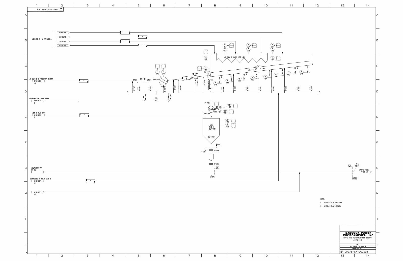


77
APPENDIX D GENERAL ARRANGEMENT DRAWINGS
Drawing Description 100276-GA200-01 Plan View 100276-GA100-01 Elevation View Looking North 100276-GA101-01 Elevation View Looking East 100276-ISO100-01 Isometric View Looking Northwest 100276-ISO101-01 Isometric View Looking Southeast