Embed Size (px)
Citation preview

GUIDANCE NOTES ON
THE APPLICATION OF FIBER ROPE FOR OFFSHOREMOORINGJUNE 2021
American Bureau of ShippingIncorporated by Act of Legislature ofthe State of New York 1862
© 2021 American Bureau of Shipping. All rights reserved.1701 City Plaza DriveSpring, TX 77389 USA

Foreword (1 June 2021)These Guidance Notes have been prepared to assist the industry with standardized criteria for applicationsof fiber ropes in offshore mooring systems. These Guidance Notes describe criteria for design, materials,testing, manufacturing, installation and subsequent survey of fiber ropes to be used in offshore mooringsystems to be classed or certified by ABS. These Guidance Notes should be used in conjunction with otherRules and Guides published by the American Bureau of Shipping as specified herein. During thepreparation of these Guidance Notes, ABS recognizes that industry participation is a vital factor due torapidly progressing nature of this technology, and for the success of developing an appropriate standardwhich satisfies practical classification requirements. ABS appreciates the industry’s input in thedevelopment of these Guidance Notes.
These Guidance Notes supersede the ABS Guidance Notes on the Application of Synthetic Ropes forOffshore Mooring, 1999. The main purpose of these new Guidance Notes is to reflect the latest technologydevelopments and industry practice for applications of fiber ropes in offshore mooring systems.
These Guidance Notes provide detailed guidance for three fiber materials: polyester, HMPE (high moduluspolyethylene), and aramid (aromatic polyamide). This does not exclude the use of other fibers in the designof mooring systems, provided that good engineering practice is followed, all relevant fiber properties areconsidered and justification for the use is adequately documented. Designers of mooring system areencouraged to consult fiber rope experts and manufactures when other rope materials are considered.
The June 2021 edition aligns the tension and fatigue design criteria with the ABS Guide for PositionMooring Systems.
These Guidance Notes become effective on the first day of the month of publication.
Users are advised to check periodically on the ABS website www.eagle.org to verify that this version ofthese Guidance Notes is the most current.
We welcome your feedback. Comments or suggestions can be sent electronically by email [email protected].
ABS GUIDANCE NOTES ON THE APPLICATION OF FIBER ROPE FOR OFFSHORE MOORING • 2021 ii

GUIDANCE NOTES ON
THE APPLICATION OF FIBER ROPE FOR OFFSHOREMOORING
CONTENTSSECTION 1 General................................................................................................10
1 Scope............................................................................................102 Definitions..................................................................................... 11
SECTION 2 Scope and Procedure for Design and Analysis ............................. 161 General.........................................................................................162 Submission of Design, Testing, Manufacturing, and Survey
Documentation..............................................................................163 Mooring Configuration.................................................................. 174 Fiber Rope Types Covered by these Guidance Notes................. 17
TABLE 1 Documentation for Design, Testing, Manufacturing, andSurvey..................................................................................16
SECTION 3 Polyester Mooring Design and Analysis ........................................ 181 Mooring System Arrangement......................................................18
1.1 Top Steel Section.............................................................181.2 Bottom Steel Section....................................................... 18
2 Stiffness Characteristics............................................................... 183 Stiffness Model............................................................................. 19
3.1 Static-Dynamic Model......................................................193.2 Upper-Lower Bound Model..............................................203.3 Other Stiffness Models.................................................... 21
4 Dynamic Stiffness......................................................................... 214.1 Equation for Dynamic Stiffness........................................214.2 Effect of Load Amplitude..................................................224.3 Effect of Loading Period.................................................. 224.4 Effect of Load History...................................................... 22
5 Static Stiffness.............................................................................. 225.1 Recommended Static Stiffness Model.............................225.2 Alternative Static Stiffness Model.................................... 235.3 Effect of Load History...................................................... 245.4 Effect of Preload Level.....................................................24
ABS GUIDANCE NOTES ON THE APPLICATION OF FIBER ROPE FOR OFFSHORE MOORING • 2021 iii

6 Stiffness Values for Preliminary Design........................................247 Determination of Stiffness Based on Test Data............................ 248 Mooring Analysis Procedure.........................................................24
8.1 Major Conclusions from Parametric Studies....................248.2 Analysis Procedure Based on the Static-Dynamic
Model............................................................................... 248.3 Analysis Procedure Based on the Upper-Lower
Bound Model....................................................................249 Mooring Analysis Examples..........................................................2510 Creep............................................................................................2511 Fatigue..........................................................................................25
11.1 Tension-Tension Fatigue..................................................2511.2 Axial Compression Fatigue..............................................26
12 Torque Compatibility..................................................................... 2612.1 Permanent Mooring......................................................... 2712.2 MODU Mooring................................................................27
13 Delayed Preloading...................................................................... 2714 MODU Mooring Considerations....................................................28
TABLE 1 Fatigue Life Factor of Safety ...............................................26
FIGURE 1 Static-Dynamic Stiffness Model........................................... 20FIGURE 2 Upper-Lower Bound Stiffness Model................................... 21FIGURE 3 Definition of Quasi-Static Stiffness.......................................23FIGURE 4 Polyester Fatigue Design Curve.......................................... 26
SECTION 4 HMPE Mooring Design and Analysis............................................... 291 HMPE Rope Strength and Stiffness Properties............................ 292 HMPE Creep ................................................................................30
2.1 Effect of Time and Creep Regimes..................................302.2 Effect of Applied Load and Temperature......................... 312.3 Creep Analysis.................................................................322.4 Creep Rupture Analysis...................................................332.5 Creep Model Verification..................................................34
3 Quasi-Static Stiffness................................................................... 344 Fatigue..........................................................................................35
4.1 Tension-Tension Fatigue..................................................354.2 Axial Compression Fatigue..............................................35
TABLE 1 Typical Rope Weights and Sizes for 10,000 kN BreakStrength ...............................................................................29
FIGURE 1 Comparison of Static and Dynamic Stiffness of ThreeFiber Materials .................................................................... 30
ABS GUIDANCE NOTES ON THE APPLICATION OF FIBER ROPE FOR OFFSHORE MOORING • 2021 iv

FIGURE 2 Typical HMPE Creep Curve ................................................ 31FIGURE 3 Typical HMPE Creep Rate Curve.........................................31FIGURE 4 Impact of Load and Temperature on Creep Rate ................32FIGURE 5 GOM Water Temperature Distribution .................................32
SECTION 5 Aramid Mooring Design and Analysis............................................. 361 Aramid Rope Strength and Stiffness Properties........................... 362 Axial Compression Fatigue...........................................................36
2.1 Past Experience and Current Status............................... 362.2 Acceptance Criteria......................................................... 362.3 Mooring Analysis............................................................. 37
3 Tension-Tension Fatigue...............................................................374 Creep and Creep Rupture............................................................ 37
SECTION 6 Design and Analysis for Other Fiber Ropes....................................38
SECTION 7 Summary of Design Criteria .............................................................391 Tension Criteria.............................................................................392 Fatigue Criteria............................................................................. 393 HMPE Creep.................................................................................394 Aramid Axial Compression Fatigue.............................................. 395 Torque Match with Torque Steel Wire Rope................................. 39
SECTION 8 Testing of Rope.................................................................................. 401 General.........................................................................................40
1.1 Test Requirements...........................................................401.2 Group Approval................................................................40
2 Rope Test Practice........................................................................412.1 Rope Sample................................................................... 412.2 Test Machine....................................................................422.3 Test Temperature............................................................. 432.4 Rope Design for Parallel Construction.............................43
3 Interpolation and Extrapolation of Data........................................ 434 Minimum Breaking Strength......................................................... 43
4.1 Test Procedure.................................................................434.2 Recommended Procedure to Determine MBS................ 444.3 Alternative Procedure to Determine MBS........................44
5 Elongation and Stiffness............................................................... 445.1 Installation Pre-loading Test.............................................445.2 Quasi-Static Stiffness for Post-Installation Rope............. 455.3 Quasi-Static Stiffness for Aged Rope.............................. 455.4 Dynamic Stiffness............................................................ 465.5 Group Approval................................................................47
ABS GUIDANCE NOTES ON THE APPLICATION OF FIBER ROPE FOR OFFSHORE MOORING • 2021 v

6 Splice Qualification....................................................................... 477 Particle Ingress Resistance.......................................................... 47
7.1 Test Procedure.................................................................477.2 Inspection and Testing..................................................... 48
8 Torque Match with Steel Wire Rope............................................. 499 HMPE Creep Rate Verification..................................................... 4910 Aramid Axial Compression Fatigue.............................................. 49
10.1 Test Procedure.................................................................4910.2 Data Reporting.................................................................50
TABLE 1 Test Requirements............................................................... 40TABLE 2 Group Approval....................................................................40TABLE 3 Test Sample Requirements..................................................41TABLE 4 Dynamic Stiffness Test Matrix for General Applications.......46
FIGURE 1 Typical Test Setup................................................................42FIGURE 2 Example Soil Grading.......................................................... 48
SECTION 9 Testing of Yarn................................................................................... 511 Testing of Yarn Dry Breaking Strength and Elongation.................512 Testing of Yarn Dry Creep for HMPE............................................ 513 Yarn-on-Yarn Abrasion Performance............................................51
3.1 Efficiency of Marine Finish...............................................513.2 Persistence of Marine Finish........................................... 52
4 Yarn Testing during Production.....................................................52
FIGURE 1 Minimum Requirement for Yarn-on-Yarn Abrasion Test.......52
SECTION 10 Rope Design....................................................................................... 531 General.........................................................................................532 Load Bearing Fiber....................................................................... 533 Rope Jacket..................................................................................534 Soil Filter.......................................................................................535 Termination................................................................................... 536 Rope Continuity............................................................................ 54
SECTION 11 Rope Production and Certification...................................................551 Rope Design Documentation........................................................552 Quality Control and Assurance.....................................................55
2.1 Quality Assurance Manual...............................................552.2 Quality Control Data Sheets............................................ 552.3 Quality Control Report..................................................... 55
3 Material Certification.....................................................................55
ABS GUIDANCE NOTES ON THE APPLICATION OF FIBER ROPE FOR OFFSHORE MOORING • 2021 vi

4 Rope Production Report............................................................... 555 Testing, Inspection, and Certification............................................56
5.1 General............................................................................ 565.2 Inspection, Examination, and Testing during Rope
Production........................................................................565.3 Inspection of Completed Rope Product........................... 565.4 Examination and Inspection of Terminations................... 565.5 Determination of Finished Rope Length.......................... 56
6 Marking.........................................................................................56
SECTION 12 Handling and Installation.................................................................. 581 General.........................................................................................582 Minimum Tension for Aramid Rope...............................................583 Contact with Seabed ....................................................................58
3.1 Preset Mooring................................................................ 583.2 Dropped Rope during Deployment.................................. 58
4 Preloading Operation....................................................................58
SECTION 13 Surveys During and After Installation .............................................591 General.........................................................................................592 Permanent Mooring ..................................................................... 59
2.1 Survey During Installation................................................592.2 Surveys After Installation................................................. 59
3 MODU Mooring ............................................................................604 Test Insert..................................................................................... 61
4.1 The Tradeoff of Test Insert...............................................614.2 ABS Requirement............................................................ 61
SECTION 14 Requirement for Witness by ABS Surveyor ................................... 621 Prototype and Production Testing ................................................62
1.1 Yarn Testing..................................................................... 621.2 Rope Testing....................................................................62
2 Production Tests and Inspections ................................................623 Mooring System Survey ...............................................................62
APPENDIX 1 References..........................................................................................63
APPENDIX 2 Supporting Information and Examples............................................651 Stiffness values for Preliminary Design of Polyester Moorings.... 65
1.1 Dynamic Stiffness............................................................ 651.2 Quasi-Static Stiffness...................................................... 66
2 Examples for Determination of Polyester Rope StiffnessBased on Test Data...................................................................... 66
ABS GUIDANCE NOTES ON THE APPLICATION OF FIBER ROPE FOR OFFSHORE MOORING • 2021 vii

2.1 Dynamic Stiffness............................................................ 662.2 Quasi-static Stiffness....................................................... 67
3 Major Conclusions from Parametric Studies for PolyesterMooring.........................................................................................693.1 Stiffness Model................................................................ 693.2 Dynamic and Quasi-static Stiffness................................. 693.3 Fatigue Analysis.............................................................. 70
4 Polyester Mooring Analysis Example........................................... 704.1 Determination of Dynamic Stiffness.................................704.2 Determination of Quasi-static Stiffness............................734.3 Determination of Upper and Lower Bound Stiffness........734.4 Strength Analysis Example..............................................744.5 Fatigue Analysis Example............................................... 75
5 HMPE Mooring Analysis Example................................................765.1 HMPE Creep Analysis Example...................................... 765.2 HMPE Creep Rupture Analysis Example........................ 765.3 Example of HMPE Quasi-Static Stiffness........................ 77
6 Guidance for Dynamic Stiffness Test Matrix................................. 78
TABLE 1 Dynamic Stiffness Coefficients for Preliminary Design........ 65TABLE 2 Dynamic Stiffness Values for Preliminary Design................ 66TABLE 3 Quasi-static Stiffness Values for Preliminary Design........... 66TABLE 4 Example Dynamic Stiffness Test Data................................. 67TABLE 5 Creep Data at 45% MBS......................................................68TABLE 6 Estimated Tension for Storm Environments.........................71TABLE 7 Dynamic Stiffness for Storm Environments..........................71TABLE 8 Dynamic Stiffness for Fatigue Environments....................... 72TABLE 9 Estimated Mooring Line Tensions under Spar VIM..............72TABLE 10 Dynamic Stiffness for Spar VIM........................................... 73TABLE 11 FD Analysis Results.............................................................74TABLE 12 TD Analysis Results.............................................................74TABLE 13 Example Fatigue Life Prediction.......................................... 75TABLE 14 Comparison of Fatigue life Prediction.................................. 75TABLE 15 Creep Analysis Results .......................................................76TABLE 16 Creep Rupture Analysis Results ......................................... 77
FIGURE 1 Example Quasi-static Stiffness Test Data............................ 67FIGURE 2 Determination of Creep Coefficient for Quasi-Static
Stiffness............................................................................... 68FIGURE 3 Quasi-Static Stiffness Design Chart.....................................69FIGURE 4 Spar Mooring Pattern and Environmental Directions...........71FIGURE 5 Example Quasi-Static Stiffness for HMPE .......................... 78
APPENDIX 3 Alternative Procedure to Determine MBS........................................79
ABS GUIDANCE NOTES ON THE APPLICATION OF FIBER ROPE FOR OFFSHORE MOORING • 2021 viii

1 General.........................................................................................792 Example 1 - Fixed Number of Subropes.......................................79
2.1 Assumption:..................................................................... 792.2 Procedure:....................................................................... 79
3 Example 2 - Fixed Size of Subrope.............................................. 803.1 Assumption:..................................................................... 803.2 Procedure:....................................................................... 80
TABLE 1 Alternative Method A to Determine MBS............................. 79TABLE 2 Alternative Method B to Determine MBS............................. 80
ABS GUIDANCE NOTES ON THE APPLICATION OF FIBER ROPE FOR OFFSHORE MOORING • 2021 ix

S E C T I O N 1 General
1 ScopeThe main purpose of these Guidance Notes is to describe criteria for design, material, testing,manufacturing, installation and subsequent survey of fiber ropes to be used as mooring components inoffshore mooring systems. The secondary purpose of these Guidance Notes is to highlight differencesbetween fiber rope mooring systems and typical steel mooring systems, and to provide guidance on how tohandle these differences during system design and installation.
In view of the influence of rope properties on mooring system performance, these Guidance Notes includedetails of how rope testing, mooring analysis and installation can be integrated to provide a consistentmooring system design methodology. In this matter, these Guidance Notes cover the following aspects:
● Design and Analysis Considerations of Mooring System
● Design Criteria for Mooring Components
● Design of Fiber Rope
● Testing and Production of Yarn and Rope
● Inspection and Certification during and after Rope Production
● Survey and Witness by ABS Surveyor
Where the mooring design, construction and installation details are similar or equivalent to steel wire/chainmooring systems, no further guidance is included in these Guidance Notes. These Guidance Notes are notintended to provide a comprehensive manual on all aspects of mooring design, construction andinstallation since these details are adequately covered by other recognized standards, such as API RP 2SK.
The publication of these Guidance Notes reflects the growth in offshore mooring applications for fiberropes and the need for a consolidated written guidance. These Guidance Notes summarize industryexperience and common practices in application of fiber ropes for offshore mooring and provides a generalguidance to check the integrity of fiber ropes application.
These Guidance Notes applies to fiber ropes used in the mooring system of both permanent and temporaryoffshore installations such as:
● Monohull Based FPSOs
● Semi-Submersible Based FPUs
● Mobile Offshore Drilling Units (MODUs)
● Drill-Ships
● Spar Platforms
● CALM Buoys
Therefore, these Guidance Notes should be used in conjunction with the latest ABS publications asfollows:
i) ABS Rules for Building and Classing Mobile Offshore Units (MOU Rules)
ii) ABS Rules for Building and Classing Single Point Moorings (SPM Rules)
ABS GUIDANCE NOTES ON THE APPLICATION OF FIBER ROPE FOR OFFSHORE MOORING • 2021 10

iii) ABS Rules for Building and Classing Floating Production Installations (FPI Rules)
iv) ABS Guide for Certification of Offshore Mooring Chain (Chain Guide)
These Guidance Notes are not intended to cover general marine applications of fiber ropes, such asberthing and mooring lines at piers and harbors, towing hawsers on tugs, mooring hawsers on Single PointMoorings (SPMs) and Tension Leg Platform (TLP) tendons.
2 DefinitionsAged Rope: The rope that has been subjected to preloading and subsequent environmental loads to reach afully bedded in condition.
Amplitude to Diameter Ratio (A/D): The ratio of VIM amplitude to the diameter of a Spar or column of adeep draft semisubmersible.
Aramid Rope: Rope made of aromatic polyamide fiber, which has higher strength and stiffness thanpolyester rope. The issue of axial compression fatigue needs to be addressed.
Average Breaking Strength: The average of the results of several rope break tests.
Axial Compression Fatigue: A failure mode for fiber rope such as aramid under low tension orcompression.
Bedding-In: The loading process of compaction of internal rope components to reduce construction stretch.
Creep Model: A model that generates creep and creep rupture design curves for ropes based on yarn testdata, particularly applicable to HMPE ropes.
Creep: The increase in rope length under sustained tension or cyclic loading.
Creep Rate: The creep strain over unit increment of time.
Creep Regime: The time regime that can be clearly distinguished by a different behavior of the creep ratefor an HMPE rope.
Creep Rupture: Failure of fiber rope, such as HMPE, due to continuous creep over time under a specificload and temperature.
Design Service Life: The intended life for the mooring system of a specific project. The design service lifefor the mooring system can be the same as or different from that for the floating unit.
Dynamic Stiffness: The ratio of change in load to change in strain in a rope under cyclic loading, typicallynormalized by MBS.
Elongation: The change in length between two gage marks, separated by a known distance (gage length) astension is applied to the rope or as tension is maintained over time.
Fiber Finish: A designation of the process and finish used on a fiber for a particular purpose (e.g. “marinefinish”).
Fiber Grade: A designation of the quality of a particular fiber, indicating adherence to tolerances forproperties.
Fiber Type: A designation given by the fiber producer which indicates the manner in which a particularfiber has been drawn or spun, processed, and treated with various finishes and/or oils.
FPI: Floating Production Installations as defined in the ABS FPI Rules [1].
Section 1 General 1
ABS GUIDANCE NOTES ON THE APPLICATION OF FIBER ROPE FOR OFFSHORE MOORING • 2021 11

FPSO: Floating Production Storage and Offloading Unit as defined in the ABS FPI Rules [1].
Frequency Domain (FD) Analysis: An analysis method that considers system responses in terms offrequency rather than time. The analysis will produce responses such as dynamic tension or motionresponses in a form of statistical values (standard deviation, significant, and maximum, etc.).
FSO: Floating Storage and Offloading Unit as defined in the ABS FPI Rules [1].
Group Approval: Approval for a group of different sizes of rope of the same design based on one or tworope tests.
HMPE Rope: Rope made of high modulus polyethylene fiber, which has higher strength and stiffness thanpolyester rope. The issue of creep needs to be addressed.
Jacket: A braided or plastic covering which is placed over the rope, subrope, or individual strand forprotection and to hold the rope structure together.
Lay Length: The length along the axis of a rope in which a strand makes one complete spiral around therope axis.
Low Frequency (LF) Response: The tension or motion dynamic response that has a period close to thenatural period of the moored system, typically in the range of 100 to 400 seconds.
Manufacturing Specification: A document which completely describes the process of making the rope,including instructions for each step of the manufacturing process.
Material Certificate: A document prepared by the manufacturer and the fiber producer to certify that thetype and grade of fiber material, the properties of the yarn, and the material used in rope production arethose specified in the Rope Design Specification.
Material Chemical Composition: The generic designation of a specific chemical composition and processof material used in the fiber (i.e., nylon, polypropylene, Aramid, high-modulus polyethylene).
Material Specification: A document, which completely describes the fiber material used in the rope,including the material chemical composition, the fiber producer, the fiber type and grade, and the yarn testproperties.
Minimum Bend Radius (MBR): Minimum radius to which the fiber rope can be bent without damage to therope construction (including, as applicable, the jacket).
Minimum Break Strength (MBS): The wet breaking strength guaranteed by the rope manufacturer for aspecific rope.
MODU: Mobile Offshore Drilling Unit, a floating drilling vessel that engages in exploratory drilling.
Mooring Line: A mooring component which consists of chain, wire rope, fiber rope or a combination ofthem to connect the floating unit with the anchor for stationkeeping.
Non-Dimensional Stiffness (Kr ): Stiffness normalized by MBS.
Non-Torque Component: Mooring component for which twist is not generated or negligible due to tensionvariation, such as chain and spiral strand. Polyester rope is generally non-torque but can be a torquecomponent by design.
Non-Torque-Matched Approach: The approach in which a non-torque fiber rope is connected to a torquecomponent such as 6-strand wire rope.
Section 1 General 1
ABS GUIDANCE NOTES ON THE APPLICATION OF FIBER ROPE FOR OFFSHORE MOORING • 2021 12
Parallel Construction: The most commonly used type of fiber rope construction for offshore mooringsconsisting of parallel subropes held together by a braided jacket.
Particle Ingress: Penetration of soil particles into the load bearing fiber core.
Permanent Mooring: The mooring system for a floating platform that has a long design service life,typically 20 years or more.
Polyester Rope: Rope made of polyester fiber, which is the most widely used fiber rope for offshoremooring.
Post-Installation Rope: The rope that has been subjected to a specific preload during installation.
Pre-Installation Rope: The rope that has not been subjected to a specific preload.
Preloading: A procedure applying a specific load to induce bedding in, thus reducing construction stretchand increasing rope stiffness during mooring installation.
Pretension: The tension initially set in the mooring lines for normal operation.
Production Rope Sample: A rope sample removed from production or selected after production for thepurpose of testing.
Prototype Rope Sample: A rope sample fully complying with the rope design specification made for thepurpose of testing either before an order is placed or before regular rope production begins for an order.
Quality Assurance Manual: A document which completely describes the Manufacturer’s quality controland assurance program.
Quality Control Data Sheet: A document which lists the important parameters in setting up andaccomplishing a designated step of the rope making and assembly process, including normal values andtolerances.
Quality Control Report: A document prepared at the completion of rope making and assembly whichincludes the completed quality control data sheets, material certificates, and inspection reports.
Quasi-Static Stiffness: The static stiffness, which is reduced to account for the rope creep under anenvironmental event.
Rope Assembly Interface: Any physical connection which is a permanent part of the rope assembly (e.g.,thimble) which is used to interconnect rope assemblies or to connect a rope assembly to another tensionmember (e.g., a wire rope or chain) or hardware (e.g., an anchor, a buoy, or a platform). [Note: thisexcludes shackles and other detachable links.]
Rope Assembly Length: The distance between the assembly interface points as measured at a definedtension and by a method agreed to by the Purchaser and the Manufacturer.
Rope Assembly: The rope, its terminations, and any other accessory gear such as thimble.
Rope Construction: The manner in which the fibers, yarns, strands and subropes are assembled together inmaking the rope.
Rope Design Specification: A document which describes the design of the rope, including the numbers andarrangements of strands, the strand pitch, the material chemical composition, and the manufacturingmethod.
Section 1 General 1
ABS GUIDANCE NOTES ON THE APPLICATION OF FIBER ROPE FOR OFFSHORE MOORING • 2021 13

Rope Fiber Area: The total cross-section area of load-bearing fiber in the rope, which is determined bydividing the weight of fiber per unit length by the fiber density.
Rope Production Report: A document which describes the rope product, including rope design,termination design, and assembly length, and which includes the material certificates, material test results,and the various data sheets.
Rope Termination: The method (e.g. splice, potted socket, wedged socket) by which the rope is attached tothe assembly interface.
Rope Yarn: The largest yarn-like component of a strand generally formed by twisting intermediate yarnstogether.
Rotation Property: The relative rotation between one end and the other end of a rope of unit length causedby application of tension.
Rotation: The tendency of the unrestrained end of a rope to rotate about its axis when tension is applied.
ROV: Remotely Operated Vehicle.
SD: Standard deviation.
Segment: A length of chain, steel or fiber rope with terminations that can be connected to provide therequired length of a mooring line.
Soil Filter: A barrier incorporated in fiber rope for blocking ingress of soil particles.
Spar: A type of FPI as defined in the ABS FPI Rules [1].
Splice: A termination type which is normally formed by passing the rope around a spool or similarattachment, and then separating the rope into strands or sub-ropes and tucking these strands or sub-ropesback into the rope structure.
Static Stiffness: The ratio of change in load to change in strain in a rope under slowly varying tension for aperiod of time, typically normalized to MBS.
Static-Dynamic Model: A stiffness model where the elongation under mean and cyclic load are representedby different slopes in a load versus elongation curve.
Stiffness Model: A simplified representation of the complex fiber rope load versus elongation behavior.
Stiffness: The ratio of change in load to change in strain in a rope in units of force such as kN or kips.Stiffness is typically normalized by the MBS in this document.
Strain: The ratio of elongation to the gage length over which the elongation takes place.
Strand: The largest component, which is twisted, braided, or otherwise assembled together to form thefinished sub-rope.
Subrope: The largest component, which is assembled together to form the finished rope.
Termination Specification: A document which completely describes the design of the termination and theprocess of making that termination, including materials and steps for making or assembling thetermination.
Test Insert: A short segment typically 10 m to 15 m long, placed at the top of the fiber mooring line, whichcan be taken out for testing and inspection.
Section 1 General 1
ABS GUIDANCE NOTES ON THE APPLICATION OF FIBER ROPE FOR OFFSHORE MOORING • 2021 14

Three-Slope Model: A stiffness model defined by 3 different slopes for mean load, LF, and WF dynamicload in a load versus elongation curve.
Time Domain (TD) Analysis: A dynamic analysis method that considers system responses as a function oftime. The analysis produces dynamic tension or motion responses in a form of time history.
T-N Curve: A fatigue design curve that defines the relation between the mooring line tension range andnumber of cycles to failure.
Torque Component: Mooring component for which twist is generated due to tension variation, such as 6-strand or 8-strand wire rope.
Torque-Matched Approach: The approach in which a fiber rope is designed to match the torsioncharacteristics of a torque component such as 6-strand wire rope.
Two-Slope Model: A stiffness model defined by 2 different slopes for mean load and dynamic load(combined LF and WF) in a load versus elongation curve.
Upper-Lower Bound Model: A simplified stiffness model where the rope stiffness is defined by themaximum and minimum value for a specific rope.
Vortex Induced Motion (VIM): The vessel motions of a Spar or a deep draft semisubmersible induced byvortex shedding under current.
Wave Frequency (WF) Response: The tension or motion dynamic responses that have periods of waves,typically in the range of 4 - 30 sec.
Wire Rope Construction: Rope construction resembling steel wire rope either as subrope or as full rope.
Yarn Break Strength: The average breaking load from yarn break tests.
Yarn Creep: The characteristic of the yarn to undergo a time related non-recoverable increase in lengthwhen subjected to sustained load.
Yarn Elongation: The average elongation at break from several yarn break tests.
Yarn: A general term for a bundle of untwisted or twisted fibers.
Yarn-on-Yarn Abrasion Property: The average number of cycles of tested yarns to failure at designatedloads in yarn-on-yarn abrasion tests.
Section 1 General 1
ABS GUIDANCE NOTES ON THE APPLICATION OF FIBER ROPE FOR OFFSHORE MOORING • 2021 15

S E C T I O N 2 Scope and Procedure for Design and Analysis
1 GeneralThis Section provides general guidance for the design and analysis of mooring systems incorporating fiberropes. Requirements as specified in the ABS Rules for Building and Classing Floating ProductionInstallations (FPI Rules) [1] and API RP 2SK (2005) [2] are generally applicable unless otherwiseprovided in these Guidance Notes. The purpose of design verification is to confirm that the proposedmooring system satisfies the specified design conditions, Rules, Guides and other related standards.
2 Submission of Design, Testing, Manufacturing, and SurveyDocumentationIn addition to the applicable documentation listed in the FPI Rules [1] and the ABS Rules for Building andClassing Mobile Offshore Units (MOU Rules) [3], design, testing, manufacturing, and surveydocumentation for fiber rope mooring system should include the following when applicable:
TABLE 1Documentation for Design, Testing, Manufacturing, and Survey
No. Document Responsibility
1 Mooring Design and Analysis Mooring Designer
2 Minimum Breaking Strength Test Rope Manufacturer
3 Elongation and Stiffness Test Rope Manufacturer
4 Splice Qualification Test Rope Manufacturer
5 Particle Ingress Resistance Test Rope Manufacturer
6 Torque Match with Steel Wire Rope Test Rope Manufacturer or Mooring Designer
7 HMPE Creep Rate Verification Test Rope Manufacturer
8 HMPE Creep and Creep Rupture Models and Basis Fiber Producer
9 Aramid Axial Compression Fatigue Test Rope Manufacturer
10 Yarn Dry Breaking Strength and Elongation Test Rope Manufacturer
11 Yarn on Yarn Abrasion Test Rope Manufacturer
12 Rope Design Specification Rope Manufacturer
13 Yarn Specification Rope Manufacturer or Fiber Producer
14 Manufacturing Specification Rope Manufacturer
15 Termination Specification Rope Manufacturer
16 Quality Control Report Rope Manufacturer
17 Rope Production Report Rope Manufacturer
18 Material Certificate Rope Manufacturer or Fiber Producer
ABS GUIDANCE NOTES ON THE APPLICATION OF FIBER ROPE FOR OFFSHORE MOORING • 2021 16
No. Document Responsibility
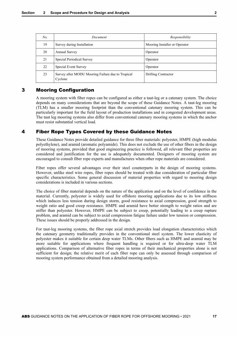
19 Survey during Installation Mooring Installer or Operator
20 Annual Survey Operator
21 Special Periodical Survey Operator
22 Special Event Survey Operator
23 Survey after MODU Mooring Failure due to TropicalCyclone
Drilling Contractor
3 Mooring ConfigurationA mooring system with fiber ropes can be configured as either a taut-leg or a catenary system. The choicedepends on many considerations that are beyond the scope of these Guidance Notes. A taut-leg mooring(TLM) has a smaller mooring footprint than the conventional catenary mooring system. This can beparticularly important for the field layout of production installations and in congested development areas.The taut leg mooring systems also differ from conventional catenary mooring systems in which the anchormust resist substantial vertical load.
4 Fiber Rope Types Covered by these Guidance NotesThese Guidance Notes provide detailed guidance for three fiber materials: polyester, HMPE (high moduluspolyethylene), and aramid (aromatic polyamide). This does not exclude the use of other fibers in the designof mooring systems, provided that good engineering practice is followed, all relevant fiber properties areconsidered and justification for the use is adequately documented. Designers of mooring system areencouraged to consult fiber rope experts and manufactures when other rope materials are considered.
Fiber ropes offer several advantages over their steel counterparts in the design of mooring systems.However, unlike steel wire ropes, fiber ropes should be treated with due consideration of particular fiberspecific characteristics. Some general discussion of material properties with regard to mooring designconsiderations is included in various sections.
The choice of fiber material depends on the nature of the application and on the level of confidence in thematerial. Currently, polyester is widely used for offshore mooring applications due to its low stiffnesswhich induces less tension during design storm, good resistance to axial compression, good strength toweight ratio and good creep resistance. HMPE and aramid have better strength to weight ratios and arestiffer than polyester. However, HMPE can be subject to creep, potentially leading to a creep ruptureproblem, and aramid can be subject to axial compression fatigue failure under low tension or compression.These issues should be properly addressed in the design.
For taut-leg mooring systems, the fiber rope axial stretch provides load elongation characteristics whichthe catenary geometry traditionally provides in the conventional steel system. The lower elasticity ofpolyester makes it suitable for certain deep water TLMs. Other fibers such as HMPE and aramid may bemore suitable for applications where frequent handling is required or for ultra-deep water TLMapplications. Comparison of alternative fiber ropes in terms of their mechanical properties alone is notsufficient for design; the relative merit of each fiber rope can only be assessed through comparison ofmooring system performance obtained from a detailed mooring analysis.
Section 2 Scope and Procedure for Design and Analysis 2
ABS GUIDANCE NOTES ON THE APPLICATION OF FIBER ROPE FOR OFFSHORE MOORING • 2021 17
S E C T I O N 3 Polyester Mooring Design and Analysis
1 Mooring System ArrangementThe fiber ropes should generally be fully submerged and freestanding, and the mooring line typicallyconsists of:
● A top steel section, which can be chain or wire rope
● A fiber rope section, which can be made of several segments for manufacturing and handling
● A bottom steel section, which can be chain or wire rope
Guidance for the top and bottom steel section for permanent moorings is provided below. The sameguidance can be considered for MODU moorings, but some of the guidance may not be directly applicableto them because of the temporary nature of the MODU operation.
1.1 Top Steel SectionFor permanent moorings, the top steel section should have a suitable length to allow fiber rope stretchingduring preloading and further stretching and creep over platform life. The top of the fiber rope should bekept well below the water surface and clear of the fairleads throughout the design service life. In areaswhere marine growth can develop inside the rope, the top of the fiber rope should be kept at a sufficientdepth based on marine growth profile to avoid such growth. In the absence of marine growth profile,currently a general industry practice is to keep the top of the fiber rope at least 100 m below the watersurface. To determine an appropriate depth, however, a number of other factors should also be considered,such as:
● The type of marine growth. Some marine growths are more harmful than other marine growths
● The type of soil filter. Some soil filters are more efficient in blocking marine growth than others
● Protective coating. Penetration of marine growth into the load bearing fiber can be blocked byeffective protective coating
In addition to above considerations, there are other factors to be considered for the length of the top steelsection, such as installation tolerances on anchor locations, fabrication length tolerance, ground chainlength tolerance and ground chain below mudline tolerance, removal of inserts, planned platformmovements for drilling or spreading out catenary riser fatigue damage by shifting the touchdown pointwhere fatigue damage is most severe.
1.2 Bottom Steel SectionFor permanent moorings, the bottom section should have a suitable length to keep the fiber rope clear ofseafloor in leeward lines under the severe storm environment (typically 100-year return period). For ropesfitted with soil filter, this condition applies only to the intact condition, provided the seafloor does notinclude hard soil and is free from other obstructions. Otherwise this condition applies to both intact anddamaged condition.
2 Stiffness CharacteristicsPolyester ropes as well as other fiber ropes are made of materials with visco-elastic properties, so theirstiffness characteristics are not constant and vary with the load duration and magnitude, the number and
ABS GUIDANCE NOTES ON THE APPLICATION OF FIBER ROPE FOR OFFSHORE MOORING • 2021 18

frequency of load cycles, and the loading history. In general, polyester mooring lines become stiffer after along time in service. Historical loading above a certain level may lead to a permanent increase of the ropelength and results in a softer mooring system if no re-tensioning is performed. Because of this complexrope behavior, it is not possible to develop models that represent the precise stiffness characteristics of therope. Currently the industry relies on some simplified models that capture the most importantcharacteristics and at the same time yield conservative prediction of line tensions and vessel offsets.
3 Stiffness ModelThe static-dynamic model [4] is recommended as the primary model for the following reasons:
● It is based on rigorous research
● It reflects the basic elongation behavior of polymer material
● It yields good approximation of line tension and vessel offset if the model parameters are properlydetermined
● Most commercial software can handle this model and therefore specialized software is not required.
● It allows efficient mooring analysis
An alternative to the static-dynamic model is the upper-lower bound model [6], which has been used by theindustry for a long time because of its simplicity and unavailability of a better model. The accuracy of thismodel depends on selection of the upper and lower bound values, and improper selection of these valuesoften leads to too conservative or non-conservative predictions. These Guidance Notes provide someguidance on establishing the upper and lower bound values for this model.
Other models have been used by the industry. They can be acceptable if they reflect the basic elongationbehavior of polymer material and produce realistic predictions. However, these Guidance Notes provide noguidance for these models, and it is up to the designer to provide evidence for the validity of the model.
3.1 Static-Dynamic Model3.1.1 Fundamental Elongation Behavior of Fiber Material
The behavior of fiber material, especially the elongation behavior, is very much dependent on themacro-molecular structure of the material (also called ‘morphology’). The morphology of polymermaterials typically shows crystalline parts and non-crystalline (amorphous) parts. Static stiffness isthe stiffness of a tension member when it is loaded slowly, leaving time for both the amorphousand crystalline part to react the load. The resulting fiber stiffness is an average of the stiffness ofboth parts. Dynamic stiffness is the stiffness response of a tension member when it is under cyclicloading. As the amorphous part does not react fast enough to the quickly changing loading regime,it is the stiffer crystalline part that takes on the load, resulting in a more ridged response of thewhole fiber [7]. For polyester rope, this behavior results in dynamic stiffness being 2 to 3 timesthe static stiffness. Failure to account for this behavior will inevitably yield inaccurate line tensionand vessel offset predictions, and the inaccuracy for vessel offset can be particularly large.
The static-dynamic model was developed to account for this fiber rope elongation behavior. In thismodel, the static stiffness is utilized for the initial region of the loading curve up to the mean load.Afterwards, the dynamic stiffness is used to predict the cyclic part of the loading (3/3.1.2 FIGURE1). This model more accurately simulates the actual conditions faced by a fiber rope mooring outat sea. A mooring line under a severe environment typically experiences a steady mean load anddynamic loads oscillating around the mean load. 3/3.1.2 FIGURE 1 represents a 2-slope modelwhere LF and WF dynamics are combined. Separating the LF and WF dynamics will result in a 3-slope model. An industry study [5] indicates that the difference between predictions from the 2-slope and 3-slope model is small, and therefore the simpler 2-slope model is recommended.
Section 3 Polyester Mooring Design and Analysis 3
ABS GUIDANCE NOTES ON THE APPLICATION OF FIBER ROPE FOR OFFSHORE MOORING • 2021 19

3.1.2 Definition of Static and Dynamic StiffnessThe stiffness of a fiber rope is expressed as:EA = ∆F∆ ε (3.1)where ΔF is the change in load, Δε is change in strain, and EA is the stiffness or the modulustimes the cross-sectional area of the rope. The stiffness is usually expressed in units of force suchas kN or kips. Equivalently, a non-dimensional stiffness Kr can also be expressed as:Kr = EAMBS (3.2)where MBS is the Minimum Breaking Strength.
In addition, these Guidance Notes deal with two types of stiffness, dynamic and static and the non-dimensional dynamic stiffness is denoted as Krd and the non-dimensional static stiffness isdenoted as Krs.
FIGURE 1 Static-Dynamic Stiffness Model
3.2 Upper-Lower Bound ModelThe upper-lower bound model was first introduced in 1999 in response to the growing needs of theindustry for a practical stiffness model for polyester mooring systems [5]. This model defines a lowerbound (post-installation) and upper bound (storm) stiffness values as a first approximation. These lowerand upper bound values are then used to calculate maximum offsets and line tensions, respectively. A plotof typical upper bound (storm) stiffness and the lower bound (post-installation) stiffness values is shown in3/3.2 FIGURE 2.
Section 3 Polyester Mooring Design and Analysis 3
ABS GUIDANCE NOTES ON THE APPLICATION OF FIBER ROPE FOR OFFSHORE MOORING • 2021 20

FIGURE 2 Upper-Lower Bound Stiffness Model
The upper-lower bound model has been widely used in the industry due to its simplicity and unavailabilityof a better model. However, it does have certain shortcomings such as:
● There is no systematic method to determine the upper and lower bound stiffness, and therefore thesevalues are often arbitrarily determined
● Polyester rope has a very complicated stiffness property, which is a function of load type, amplitude,duration, and history. Using 2 limiting values to represent the complicated behavior often results inoverly conservative or non-conservative analysis results, depending on the design parameter beingconsidered. To avoid this situation, many designers use some intermediate values, but again theselection of these values is rather arbitrary, resulting in more confusion over this issue.
Although the upper-lower bound model is a simple and widely used model, determination and use of theupper and lower bound values requires careful consideration.
3.3 Other Stiffness ModelsOther stiffness models can be acceptable if they meet the following criteria:
● The model reflects the basic elongation behavior of polymer material as discussed in 3/3.1.1
● The model produces realistic line tension and vessel offset predictions under various conditions
● The model properly accounts for line length changes due to creep and permanent elongation
4 Dynamic Stiffness
4.1 Equation for Dynamic StiffnessThe three-parameter equation [8] is recommended for dynamic stiffness:
Section 3 Polyester Mooring Design and Analysis 3
ABS GUIDANCE NOTES ON THE APPLICATION OF FIBER ROPE FOR OFFSHORE MOORING • 2021 21
Krd = α + βLm + γT + δlog P (3.3)whereLm = mean load as % of MBS (i.e., 20 is 20% of MBS)T = load amplitude as % of MBSP = loading period in seconds
There is a trend in the industry to take out the tension amplitude and loading period in the equation,claiming their impact is negligible. This leaves a simplified dynamic stiffness model depending on meanload only. Investigations reveal that this simplified model is a poor fit to the test data. To have a generalmodel for all polyester ropes, all 3 parameters should be kept, unless data are available to justify the use ofa simpler formulation.
4.2 Effect of Load AmplitudeThe tension amplitude T in Equation 3.3 is based on test data for sinusoidal loading with constantamplitude. Industry studies indicate that the effect of tension amplitude can be significantly less for theextreme response under stochastic loading [9]. Under fatigue loading, the effect of tension amplitude canbe negligible. Based on this, the following practice is recommended:
● For sinusoidal loading such as Spar VIM in the lock-in region, T is the maximum tension amplitudefor strength and fatigue analysis
● For strength analysis under stochastic loading such as storm loads or Spar VIM in the transitionregion, T is 0.5 times the maximum tension amplitude.
● For fatigue analysis under wave loading, T is negligible
4.3 Effect of Loading PeriodFor WF response, the loading period P can be taken as the response (or spectral as approximation) peakperiod. For LF response including VIM, it can be taken as the natural period of the moored system.Dynamic stiffness is not very sensitive to loading period since it is a function of log (P).
4.4 Effect of Load HistoryTo investigate the impact of load history, the rope conditions are classified in 3 categories:
1) Pre-installation: The rope has not been preloaded and therefore has the lowest stiffness
2) Post-installation: The rope has been preloaded during installation and achieved an initial beddingin
3) Aged: The rope has experienced severe loadings beyond the preload to reach a fully bedded incondition
Available test data indicate that the difference between dynamic stiffness for post installation and agedrope is small. Therefore dynamic stiffness for the aged rope can be used conservatively for the project, andtesting for both post-installation and aged rope is not necessary. Dynamic stiffness data for the pre-installation rope are not available at this point.
5 Static Stiffness
5.1 Recommended Static Stiffness ModelBased on industry investigations [5][10][11][12], a “quasi-static stiffness” model is recommended. Asshown in 3/5.1 FIGURE 3, after pre-conditioning the rope, the static test started at the pre-tension, and acreep plateau is placed at the load level of interest. The quasi-static stiffness is taken as the secant stiffness
Section 3 Polyester Mooring Design and Analysis 3
ABS GUIDANCE NOTES ON THE APPLICATION OF FIBER ROPE FOR OFFSHORE MOORING • 2021 22

connecting the point at the pre-tension with the point at the end of the creep plateau for the load level. Thecreep, which is a function of load or storm duration, can be represented by a linear function of log time.Therefore the quasi-static stiffness can be determined by Equation 3.4.
FIGURE 3 Definition of Quasi-Static Stiffness
Krs = F2 – F1 / E2 – E1 + C · log t (3.4)whereF1 = starting test tension, typically pre-tension of mooring line (%MBS)F2 = ending test tension, typically storm mean load (%MBS)E1 = starting strain (%)E2 = ending strain (%)C = creep coefficientt = duration of the environmental event
The coefficient C can be determined by regression analysis as shown in A2/2.2.
5.2 Alternative Static Stiffness ModelSome designers prefer to use the elastic stiffness instead of the quasi-static stiffness. The non-elasticelongations such as permanent elongation and creep are determined and input to the mooring analysissoftware separately. This approach can be acceptable if the elastic stiffness is properly defined and all non-
Section 3 Polyester Mooring Design and Analysis 3
ABS GUIDANCE NOTES ON THE APPLICATION OF FIBER ROPE FOR OFFSHORE MOORING • 2021 23

elastic elongations are properly accounted for. A specialized test program is required to provideappropriate test data for this approach. These Guidance Notes provide no guidance for this model.
5.3 Effect of Load HistoryAvailable test data indicate that the difference between quasi-static stiffness for pre-installation, post-installation, and aged rope can be large. For example the difference between quasi-static stiffness for post-installation and aged rope is in the range of 30% to 60% based on test data for recent projects [5].Therefore quasi-static stiffness testing for pre-installation, post-installation, and aged rope should be doneseparately, if applicable.
5.4 Effect of Preload LevelThe effect of preload level is also noticeable. For example some test data indicate that reducing the preloadfrom 40% MBS to 30% MBS may result in about 10% reduction in quasi-static stiffness.
6 Stiffness Values for Preliminary DesignDuring preliminary design, there is a need to use approximate stiffness values since the rope manufacturerfor the project may have not been determined. More accurate stiffness values based on rope specific testingare not available at this stage. In the absence of better information, guidance provided in A2/1 can be usedto determine stiffness values for preliminary design.
7 Determination of Stiffness Based on Test DataProject specific test data, if available, should be used to determine quasi-static and dynamic stiffness forthe final design. The stiffness testing should be conducted according to guidance provided in Subsection8/5. The examples in A2/2 illustrate procedures to develop the dynamic stiffness coefficients and quasi-static design curves based on test data.
8 Mooring Analysis ProcedureAnalysis procedure for fiber rope moorings is similar to that for steel moorings as presented in API RP2SK. An exception is the treatment of fiber rope stiffness, which is much more complicated than the linearstiffness for steel components. This Section provides guidance only for handling fiber rope stiffness in themooring analysis, and the designers should refer to API RP 2SK for general mooring analysis procedure.
8.1 Major Conclusions from Parametric StudiesTwo parametric studies have been conducted in the DeepStar 6403 study [10] and in the ABS JIP [5] toinvestigate the impact of stiffness models and parameters on mooring analysis results under variousconditions. The conclusions from these studies are presented in A2/3, which can serve as guidance forpractical and conservative fiber rope mooring analysis.
8.2 Analysis Procedure Based on the Static-Dynamic ModelCommercial mooring analysis software is normally not designed to handle the 2-slope static-dynamicmodel directly and therefore some approximations are needed. In typical industry practice, the mooringanalysis is performed twice, one with the quasi-static stiffness and another one with the dynamic stiffness.Then the mean responses (tension and offset) from the first run are combined with the dynamic responsesfrom the second run to yield the final results. The pre-tension for both runs should be the same. To achievethis, the line length or anchor location may have to be adjusted in the second run when the quasi-staticstiffness is changed to dynamic stiffness. This procedure applies to both FD and TD analysis.
8.3 Analysis Procedure Based on the Upper-Lower Bound ModelThe analysis procedure is similar to that for the static-dynamic model. The mooring analysis is performedtwice, one with the lower bound stiffness and another one with the upper bound stiffness. Then themaximum offset is determined by the first run, and the maximum line tension is determined by the second
Section 3 Polyester Mooring Design and Analysis 3
ABS GUIDANCE NOTES ON THE APPLICATION OF FIBER ROPE FOR OFFSHORE MOORING • 2021 24

run. Again the pre-tension for both runs should be the same. To achieve this, the line length or anchorlocation may have to be adjusted in the second run when the lower bound stiffness is changed to the upperbound stiffness. This procedure applies to both FD and TD analysis.
9 Mooring Analysis ExamplesExamples of stiffness determination, strength and fatigue analysis are provided in A2/4.
10 CreepPolyester ropes are not subject to significant creep at loads normally experienced in mooring applicationsand thus are not normally subject to failure due to creep rupture. Therefore creep or creep rupture analysisis not required for mooring design. However, mooring line adjustments may be needed during designservice life due to rope creep, and sufficient upper chain segment length should be retained to allow futureline adjustments. Estimate of future line adjustments can be carried out using the creep rates at the creepplateaus from the quasi-static stiffness test.
11 Fatigue
11.1 Tension-Tension FatigueThe recommended polyester fatigue design curve is the “mean minus two standard deviation” curve fromthe JIP investigating the durability of polyester ropes [13]. This design curve is represented by thefollowing design equation and the plot in 3/11.1 FIGURE 4. Polyester ropes have much better fatigueresistance than chain and steel wire ropes, and therefore fatigue evaluation is typically focused on theupper chain segment, which has the shortest fatigue life.NRM = K (3.5)whereN = number of cyclesR = ratio of tension range (double amplitude) to MBSM = 5.2 (slope of T-N curve)K = 25,000 (intercept of T-N curve)
Section 3 Polyester Mooring Design and Analysis 3
ABS GUIDANCE NOTES ON THE APPLICATION OF FIBER ROPE FOR OFFSHORE MOORING • 2021 25

FIGURE 4 Polyester Fatigue Design Curve
As per the ABS FPI Rules [1], tension-tension fatigue life design criteria can be summarized in thefollowing table for permanent installations. For temporary installations, fatigue analysis can be waivedprovided that inspection of the mooring is conducted according to API RP 2I [14].
TABLE 1Fatigue Life Factor of Safety
Area Component Fatigue Life/Design Service Life
Inspectable Areas 3
Non-Inspectable and Critical Areas 10
11.2 Axial Compression FatigueAxial compression fatigue is not a concern with polyester ropes, and therefore axial compression fatigueanalysis and testing are not required.
12 Torque CompatibilityTorque compatibility should be considered between polyester rope and other components such as chain andwire rope. There are 2 torque categories for mooring components:
● Torque component: Twist is generated due to tension variation, such as 6-strand or 8-strand wire rope
● Non-torque component: Twist is not generated or negligible due to tension variation, such as chain andspiral strand. Polyester rope is generally non-torque but can be a torque component by design.
Section 3 Polyester Mooring Design and Analysis 3
ABS GUIDANCE NOTES ON THE APPLICATION OF FIBER ROPE FOR OFFSHORE MOORING • 2021 26
Laboratory testing demonstrates that a 6- or 8-strand wire rope’s fatigue performance, when connectedwith a non-torque polyester rope, could be significantly degraded, although the scale effect of such testingis yet to be quantified. Following is some guidance to address this issue.
12.1 Permanent MooringNon-torque polyester rope should generally be used with non-torque steel components such as chain orspiral strand to achieve a non-torque mooring line. Should special situation dictate the use of a polyesterrope with a torque steel component such as 6- or 8-strand wire rope, the polyester rope should be designedto have similar torque characteristics as the steel component to achieve a torque-matched mooring line. Atorque match test should be conducted for the polyester rope and the wire rope according to the testprocedure presented in Subsection 8/8, and the angular rotation in the wire rope should not exceed 5°perrope lay length.
12.2 MODU MooringA large number of MODUs use torque steel components, mostly 6-strand wire rope, especially fordeepwater operations. Special considerations should be given to MODU operations, which are typically ofshort duration and in different water depths and environments. Industry experience indicates that there areat least two viable design approaches for MODU moorings.
12.2.1 Torque-matched ApproachA steel wire rope’s fatigue life is best preserved by connecting to a torque-matched polyester rope.A rope is considered torque matched if its torsion characteristics over the design load range areessentially the same as that of the connected wire rope. Due to the inherent difference in materialproperties, a polyester rope typically can only match a wire rope’s torsion characteristics at a pre-determined tension range. The difference between the torque of the polyester rope and wire ropeincreases as the line tension deviates from the match point with changing environmental loadingor heading. Other factors to be considered in the torque-matched design include torquecharacteristics, lay direction, presence of swivels in the mooring lines, swivel lock-up load, andthe presence and length of chain segments.
If this approach is used, a torque match test should be conducted (see 3/12.1).
12.2.2 Non-torque-matched ApproachAvailable non-torque polyester ropes can be used for short term MODU mooring systems if thedynamic torsion of the steel wire could be restrained at the interface between the fiber rope andwire rope [15]. A properly designed submersible buoy could provide such restraint. Availableexperience shows that wire rope fatigue damage in such a system is lower than some of the earlierscaled test data suggest [15]. The fatigue damage to wire rope tends to be concentrated near theinterface with the polyester rope. The wire rope can be returned to service after the damaged endis re-terminated during a MODU move. It is also possible to insert a short wire rope insert (200 ftto 300 ft) between the wire rope and the polyester rope to minimize the need for re-socketing wireropes in the field.
13 Delayed PreloadingThe preloading operation to achieve initial bedding-in of the polyester ropes should be carried outimmediately after the mooring installation. If this operation is delayed for an extended period during whichsevere environments can be encountered, a mooring analysis should be conducted using the stiffnessvalues for a pre-installation rope. Vessel offsets and motions from this analysis should be used to checkthat riser stress and fatigue life are sufficient to provide riser integrity under this condition.
Section 3 Polyester Mooring Design and Analysis 3
ABS GUIDANCE NOTES ON THE APPLICATION OF FIBER ROPE FOR OFFSHORE MOORING • 2021 27

14 MODU Mooring ConsiderationsThe guidance in this document is mainly based on the industry experience from permanent mooringprojects, and most of the guidance is expected to be applicable to MODU moorings. However, there areareas where a MODU mooring is different from a permanent mooring, and special attention should be paidto these areas, such as:
● The requirements for the top and bottom steel section can be different (Subsection 3/1)
● Polyester rope for MODU moorings is often not preloaded or preloaded with a much lower tension.This may result in a very soft rope when it is new, but the rope becomes stiffer as it ages. This shouldbe taken into consideration when conducting stiffness test and mooring analysis. This is particularlyimportant for deepwater operations where stroking out of the riser slip joint is possible due to largevessel offset.
● The practice for torque compatibility is different (Subsection 3/12)
● Determination of dynamic and quasi-static stiffness values is based on a few design parameters, suchas mean tension, tension amplitude, duration of the environmental event, natural period of the mooredsystem, etc. MODU operations are typically of short duration and in different water depths andenvironments, and therefore these design parameters are often uncertain. Simplified and conservativeassumptions should be used to determine these parameters.
Section 3 Polyester Mooring Design and Analysis 3
ABS GUIDANCE NOTES ON THE APPLICATION OF FIBER ROPE FOR OFFSHORE MOORING • 2021 28

S E C T I O N 4 HMPE Mooring Design and Analysis
The guidance for polyester mooring design and analysis is generally applicable to HMPE moorings. Themajor issue of HMPE is its tendency to creep, which should be properly addressed, as discussed in thefollowing sections.
1 HMPE Rope Strength and Stiffness PropertiesHMPE possesses several desirable properties for mooring operations. They are naturally buoyant, havehigh abrasion resistance and possess a strength-to-diameter ratio much higher than that of polyester rope,as shown in 4/1 TABLE 1 [28]. Note the values in this table are indicative only and should not be used fordesign. Additionally, HMPE possesses higher static and dynamic stiffness over aramid and polyester asseen in 4/1 FIGURE 1 [16][17]. However, quasi-static stiffness of HMPE is strongly dependent on stormduration as discussed in Subsection 4/3.
TABLE 1Typical Rope Weights and Sizes for 10,000 kN Break Strength
Rope Property Polyester Aramid HMPE Steel (for comparison)
Total weight in air (kg/m) 23.0 12.0 8.4 57.0
Total weight in water (kg/m) 5.9 3.3 Buoyant 48.0
Typical overall diameter (mm) 175.0 120.0 125.0 108.0
ABS GUIDANCE NOTES ON THE APPLICATION OF FIBER ROPE FOR OFFSHORE MOORING • 2021 29

FIGURE 1 Comparison of Static and Dynamic Stiffness of Three Fiber Materials
2 HMPE CreepThe major issue of HMPE is its tendency to creep, which should be addressed in the design of permanentmoorings. One of the main concerns with HMPE's high creep rate is the potential for failure via creeprupture. As a HMPE rope creeps under tension, eventually it stretches to the point of complete failure.Another concern is the need for re-tensioning because of HMPE's high creep rate. Furthermore the highcreep rate can lower the quasi-static stiffness over long storm duration. Factors affecting HMPE creepbehavior are fiber type, applied load, time, and temperature, as discussed below.
Similar considerations should also be given to MODU moorings, but the concern for creep and creeprupture is less for MODU operations because of the short duration of these operations.
2.1 Effect of Time and Creep Regimes4/2.1 FIGURE 2 shows a typical creep curve of HMPE, where the strain is plotted as a function of time.The logarithmic creep rate of this experiment, which is the slope of this curve, is shown in 4/2.1 FIGURE3. Three regimes can be clearly distinguished by a different behavior of the creep rate [18].
● Regime I “primary creep”: In this regime the amorphous realignment takes place, and the high creeprate at start reduces to a plateau level at the end. The strain is reversible with the use of an elastic anddelayed elastic component.
● Regime II: “steady state creep”: In this regime the sliding of molecular chains takes place. The creeprate increases slightly because under a constant load the yarn stress actually increases slightly as creepcontinues. For practical purpose the creep rate can be considered constant for this regime. The strain iscalled “plastic creep”, which is irreversible.
Section 4 HMPE Mooring Design and Analysis 4
ABS GUIDANCE NOTES ON THE APPLICATION OF FIBER ROPE FOR OFFSHORE MOORING • 2021 30

● Regime III: “tertiary creep”: In this regime molecular chains start to break. High strains will start tocause necking in the filaments and will increase the local stress that further accelerates the strain untilbreakage.
FIGURE 2 Typical HMPE Creep Curve
FIGURE 3 Typical HMPE Creep Rate Curve
2.2 Effect of Applied Load and TemperatureThe creep rate of HMPE yarn is also dependent upon the applied load and temperature. 4/2.2 FIGURE 4shows an example of creep rate as a function of applied load and temperature based on yarn creep test for aspecific HMPE fiber [18].
Section 4 HMPE Mooring Design and Analysis 4
ABS GUIDANCE NOTES ON THE APPLICATION OF FIBER ROPE FOR OFFSHORE MOORING • 2021 31

FIGURE 4 Impact of Load and Temperature on Creep Rate
It can be seen that creep rate increases with increasing temperature. 4/2.2 FIGURE 5 shows the meanannual water temperature as a function of water depth for GOM [19]. To avoid excessive creep, HMPEropes should be placed at a depth where the creep performance meets the design criteria.
FIGURE 5 GOM Water Temperature Distribution
2.3 Creep AnalysisA creep analysis should be performed for an intact mooring to estimate the total creep strain during thedesign service life, which should be limited to 10% for the total length of the HMPE rope. To simplify theanalysis, the following assumptions are made:
● Regime I is of short duration compared with design service life and therefore creep in this regime canbe neglected
● The creep in Regime II is estimated using a constant creep rate for time, but the creep rate is still afunction of applied load and temperature
Section 4 HMPE Mooring Design and Analysis 4
ABS GUIDANCE NOTES ON THE APPLICATION OF FIBER ROPE FOR OFFSHORE MOORING • 2021 32

● Creep rates as a function of yarn stress and temperature relevant to the project are available. Theserates are typically generated based on yarn test data and a creep model
● Information about the rope design and unit mass is available so yarn stress can be converted to ropetension (%MBS) by a conversion factor for a particular rope
● The strain in Regime II is defined as plastic creep that is irreversible, and therefore creep iscumulative. The annual cumulative creep strain, Gt can be calculated by the following equation for aspecific temperature:Gt = ΣℎiHi (4.1)whereℎi = duration per year within the tension interval i,Hi = creep rate for the tension interval i
The recommended procedure for a creep analysis is described below.
i) The long-term environmental events can be represented by a number of discrete design conditions.Each design condition consists of a reference direction and a reference sea state characterized bysignificant wave height, peak spectral period, spectral shape, current velocity, and wind velocity.The probability of occurrence of each design condition should be specified.
ii) For each design condition, determine the mean tensions for all mooring lines.
iii) Compute the annual creep strain from one design condition (one sea state in one direction) usingEquation 4.1.
iv) Repeat iii) for all sea states and directions and compute the annual creep strain Gt, which is thesum of creep strain from all sea states and directions.
v) The predicted total creep strain of the mooring line for a design service life M(year) is:G = MGt (4.2)Special attention should be given to the high current event such as the Loop current event in the Gulf ofMexico, which can impose high steady loads of long duration on the floating structure. Such an eventshould be included in the design conditions for creep analysis.
A creep analysis example is provided in A2/5.1.
2.4 Creep Rupture AnalysisA creep rupture analysis should be performed for an intact mooring to estimate the creep rupture life,which should be greater than 5 times the design service life if creep is monitored. The creep rupture lifeshould be greater than 10 times the design service life if creep is not monitored. To simplify the analysis,the following assumptions are made:
● Regime III is of short duration compared with design service life and therefore creep rupture isconservatively assumed at the start of Regime III.
● Creep rupture time as a function of yarn stress and temperature relevant to the project are available.This information is typically generated based on yarn test data and a creep model
● Information about the rope design and unit mass is available so yarn stress can be converted to ropetension (%MBS) by a conversion factor for a specific rope
● Similar to the Miner’s rule for fatigue analysis, the annual cumulative creep rupture damage ratio Bcan be calculated by the following equation:
Section 4 HMPE Mooring Design and Analysis 4
ABS GUIDANCE NOTES ON THE APPLICATION OF FIBER ROPE FOR OFFSHORE MOORING • 2021 33

B = Σci/Ci (4.3)whereci = duration per year within the tension interval i,Ci = creep rupture time for the tension interval iThe predicted creep rupture life for the mooring component is 1/B.
The recommended procedure for a creep rupture analysis is described below.
i) The long-term environmental events can be represented by a number of discrete design conditions.Each design condition consists of a reference direction and a reference seastate characterized bysignificant wave height, peak spectral period, spectral shape, current velocity, and wind velocity.The probability of occurrence of each design condition should be specified.
ii) For each design condition, determine the mean tension for all mooring lines.
iii) Compute the annual creep rupture damage from one design condition (one seastate in onedirection) using Equation 4.3.
iv) Repeat iii) for all seastates and directions and compute the total annual creep rupture damage Bt,which is the sum of creep rupture damage from all seastates and directions.
v) The predicted creep rupture life of the mooring line is:L = 1/Bt (years) (4.4)Unlike fatigue damage that is mainly caused by cyclic loading from waves, creep rupture damage can besignificantly contributed by all environmental parameters including wind, waves, and current. Specialattention should be given to the high current event such as the Loop current event in the Gulf of Mexico,which can impose high steady loads of long duration on the floating structure. Such an event should beincluded in the design conditions for creep rupture analysis.
A creep rupture analysis example is provided in A2/5.2.
2.5 Creep Model VerificationThe creep model generating design data for creep and creep rupture analysis should be verified by averification test for rope creep rate at least one load and one temperature according to the procedurespecified in Subsection 8/9. If the design data used in the analysis are found to be non-conservative, theyshould be adjusted using the verification test results, and the creep and creep rupture analysis should berepeated. To properly adjust the design data, additional tests for rope creep rate may be necessary.
3 Quasi-Static StiffnessCreep has much higher impact on the quasi-static stiffness for HMPE than for polyester. Equation 3.4 in3/5.1 should be modified to the following equation for HMPE:Krs = ( F2 – F1 )/( E2 – E1 + Ct (4.5)whereF1 = starting test tension, typically pre-tension of mooring line (%MBS)F2 = ending test tension, typically storm mean load (%MBS)E1 = starting strain (%)
Section 4 HMPE Mooring Design and Analysis 4
ABS GUIDANCE NOTES ON THE APPLICATION OF FIBER ROPE FOR OFFSHORE MOORING • 2021 34
E2 = ending strain (%)C = creep coefficientt = duration of the environmental event
An example for HMPE quasi-static stiffness is provided in A2/5.3.
4 Fatigue
4.1 Tension-Tension FatigueLimited fatigue test data for HMPE rope indicates that HMPE rope may have comparable fatigueresistance to polyester rope, but the fatigue design curve cannot be generated at this point. Fatigue analysisshould be focused on the upper chain segment, and the tension range for the upper chain should be basedon proper stiffness values for the HMPE rope.
4.2 Axial Compression FatigueAxial compression fatigue is not a concern with HMPE ropes, and therefore axial compression fatigueanalysis and testing are not required.
Section 4 HMPE Mooring Design and Analysis 4
ABS GUIDANCE NOTES ON THE APPLICATION OF FIBER ROPE FOR OFFSHORE MOORING • 2021 35
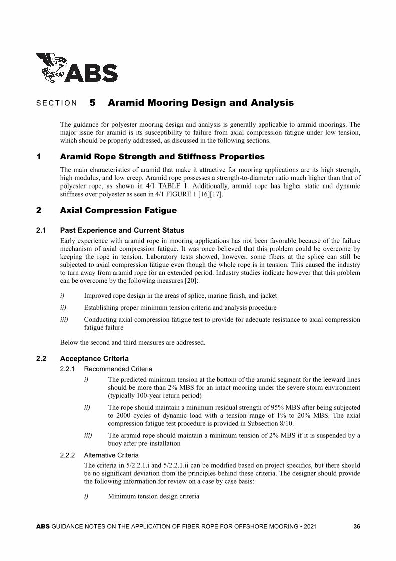
S E C T I O N 5 Aramid Mooring Design and Analysis
The guidance for polyester mooring design and analysis is generally applicable to aramid moorings. Themajor issue for aramid is its susceptibility to failure from axial compression fatigue under low tension,which should be properly addressed, as discussed in the following sections.
1 Aramid Rope Strength and Stiffness PropertiesThe main characteristics of aramid that make it attractive for mooring applications are its high strength,high modulus, and low creep. Aramid rope possesses a strength-to-diameter ratio much higher than that ofpolyester rope, as shown in 4/1 TABLE 1. Additionally, aramid rope has higher static and dynamicstiffness over polyester as seen in 4/1 FIGURE 1 [16][17].
2 Axial Compression Fatigue
2.1 Past Experience and Current StatusEarly experience with aramid rope in mooring applications has not been favorable because of the failuremechanism of axial compression fatigue. It was once believed that this problem could be overcome bykeeping the rope in tension. Laboratory tests showed, however, some fibers at the splice can still besubjected to axial compression fatigue even though the whole rope is in tension. This caused the industryto turn away from aramid rope for an extended period. Industry studies indicate however that this problemcan be overcome by the following measures [20]:
i) Improved rope design in the areas of splice, marine finish, and jacket
ii) Establishing proper minimum tension criteria and analysis procedure
iii) Conducting axial compression fatigue test to provide for adequate resistance to axial compressionfatigue failure
Below the second and third measures are addressed.
2.2 Acceptance Criteria2.2.1 Recommended Criteria
i) The predicted minimum tension at the bottom of the aramid segment for the leeward linesshould be more than 2% MBS for an intact mooring under the severe storm environment(typically 100-year return period)
ii) The rope should maintain a minimum residual strength of 95% MBS after being subjectedto 2000 cycles of dynamic load with a tension range of 1% to 20% MBS. The axialcompression fatigue test procedure is provided in Subsection 8/10.
iii) The aramid rope should maintain a minimum tension of 2% MBS if it is suspended by abuoy after pre-installation
2.2.2 Alternative CriteriaThe criteria in 5/2.2.1.i and 5/2.2.1.ii can be modified based on project specifics, but there shouldbe no significant deviation from the principles behind these criteria. The designer should providethe following information for review on a case by case basis:
i) Minimum tension design criteria
ABS GUIDANCE NOTES ON THE APPLICATION OF FIBER ROPE FOR OFFSHORE MOORING • 2021 36

ii) Axial compression fatigue test procedure: tension range, number and frequency of testcycles
iii) Residual strength after test
iv) Basis for the design criteria and test procedure
2.3 Mooring AnalysisFrequency domain analysis may not yield an accurate prediction for minimum tension in leeward lines,and time domain analysis is preferred. If frequency domain analysis is used, it should be first verified bytime domain analysis.
3 Tension-Tension FatigueTension-Tension fatigue design curve cannot be generated at this point because of lack of data. Fatigueanalysis should be focused on the upper chain segment, and the tension range for the upper chain should bebased on proper stiffness values for the aramid rope.
4 Creep and Creep RuptureAramid rope has better resistance to creep than polyester and HMPE rope, and therefore creep and creeprupture analysis are not required for mooring design.
Section 5 Aramid Mooring Design and Analysis 5
ABS GUIDANCE NOTES ON THE APPLICATION OF FIBER ROPE FOR OFFSHORE MOORING • 2021 37

S E C T I O N 6 Design and Analysis for Other Fiber Ropes
There are fiber materials other than polyester, HMPE, and aramid that can be considered for mooringapplications. These Guidance Notes cannot give specific guidance for them at this point because of lack oftechnical data. Some of the guidance in this document may be applicable to other fiber materials, but theuser should exercise caution and sound judgment in such applications.
ABS GUIDANCE NOTES ON THE APPLICATION OF FIBER ROPE FOR OFFSHORE MOORING • 2021 38

S E C T I O N 7 Summary of Design Criteria
1 Tension Criteria (1 June 2021)For tension limits and factors of safety for intact and one line damaged condition for the most loaded linebased on dynamic analysis, refer to 3/7.7 of the ABS Guide for Position Mooring Systems.
2 Fatigue Criteria (1 June 2021)For factors of safety for fatigue life, refer to 3/7.7 of the ABS Guide for Position Mooring Systems.
3 HMPE Creep● Creep strain limit for design service life: 10%
● Factor of safety against creep rupture: 5 (creep is monitored) or 10 (creep is not monitored)
4 Aramid Axial Compression Fatigue● Minimum tension for leeward line under intact condition: 2% MBS
● Minimum residual strength of 95% MBS after 2000 cycles of dynamic load with a tension range of 1%to 20% MBS.
● Minimum tension of 2% MBS if it is suspended by a buoy after pre-installation
5 Torque Match with Torque Steel Wire RopeThe angular rotation in the steel wire rope should not exceed 5 degrees per rope lay length based on thetest procedure specified in Subsection 8/8.
ABS GUIDANCE NOTES ON THE APPLICATION OF FIBER ROPE FOR OFFSHORE MOORING • 2021 39

S E C T I O N 8 Testing of Rope
1 GeneralThis Section provides guidance for conducting rope tests to determine fiber rope properties.
1.1 Test RequirementsA summary of test requirements for different fibers and operating conditions is given in 8/1.1 TABLE 1.
TABLE 1Test Requirements
Subsection Test Type Fiber Type Requirement
8/4 Minimum Breaking Strength All Required
8/5 Elongation and Stiffness All Required
8/6 Splice Qualification All Required
8/7 Particle Ingress Resistance All *
8/8 Torque Match with Steel Wire Rope All **
8/9 HMPE Creep Rate Verification HMPE Required
8/10 Aramid Axial Compression Fatigue Aramid Required
Note:* Required for rope preset on seabed and reuse of an accidentally dropped rope** Required for fiber rope connected with torque wire rope (6- or 8-strand) for permanent mooring
1.2 Group ApprovalApproval for a group of different sizes of rope of the same design based on 1 or 2 rope tests is acceptablein some cases, as indicated in 8/1.2 TABLE 2.
TABLE 2Group Approval
Subsection Test Type Group Approval
8/4 Minimum Breaking Strength No
8/5 Elongation and Stiffness Dynamic stiffness only
8/6 Splice Qualification Yes
8/7 Particle Ingress Resistance Yes
8/8 Torque Match with Steel Wire Rope No
8/9 HMPE Creep Rate Verification No
8/10 Aramid Axial Compression Fatigue Yes
ABS GUIDANCE NOTES ON THE APPLICATION OF FIBER ROPE FOR OFFSHORE MOORING • 2021 40

Conditions for group approval are as follows:
i) Group approval is effective for no more than 5 years from the test date
ii) One sample: qualify ropes within ±20% of MBS of the test sample
iii) Two samples: qualify ropes between 80% MBS of the small and 120% MBS of the large testsample. The 2-sample approach is not applicable to dynamic stiffness test.
iv) Group approval applies only to ropes with same design parameters as indicated below:
● Subrope construction
● Yarn type
● Number of layers in eye configuration
● D/d ratio for hardware
● Shape of hardware bearing surface
● Splice lengths (number of strand tucks and tapered tucks)
● Chafe protection material and application in the eye
● Soil filter material and design (for “Particle Ingress Resistance” test only)
2 Rope Test Practice
2.1 Rope SampleThe rope tests may be performed on a prototype rope after the rope design is documented by themanufacturer before an order is received or on a sample rope taken before, during or after production of anorder. The ropes to be tested should be identical in material and construction to the production ropes,except as noted. Test sample requirements are summarized in 8/2.1 TABLE 3
TABLE 3Test Sample Requirements
Subsection Test Type Subrope SampleAllowed for
ParallelConstruction?
Same Splice asProduction Rope
Required?
MinimumSample Length
8/4 Minimum Breaking Strength No Yes 40D
8/5 Elongation and Stiffness Yes No 5 m
8/6 Splice Qualification No Yes 40D
8/7 Particle Ingress Resistance No Yes 40D
8/8 Torque Match with Steel Wire Rope No Yes Same length assteel wire rope
8/9 HMPE Creep Rate Verification Yes No 5 m
8/10 Aramid Axial Compression Fatigue No Yes 40D
Section 8 Testing of Rope 8
ABS GUIDANCE NOTES ON THE APPLICATION OF FIBER ROPE FOR OFFSHORE MOORING • 2021 41
Notes:
1 All samples should be full rope samples with 2 exceptions for tests of parallel construction ropes. Subropesamples can be used for these 2 tests, and the subrope MBS can be taken as the full rope MBS divided by thenumber of subropes.
2 The sample length is the length between the bearing points (8/2.1 FIGURE 1). D is sample diameter
3 The samples should be terminated in the same manner as the production with exception for 2 tests. For these twotests the terminations should be of sufficient strength to safely withstand at least 70% of the rope MBS. Thesample length should be at least 5 m. The gage marks should be no closer than 3 times rope diameter from the lasttuck of rope splices.
4 In general, the sample should not have been previously tensioned to more than 5% of its estimated breakingstrength nor have been maintained under steady or cyclic tension except as noted. This criterion does not apply tothe test for used ropes.
5 The entire sample including terminations should be soaked in fresh water for 4 hours (subrope) or 12 hours (fullrope) before testing. The sample should be tested as soon as practical after being removed from the water. If thereis a delay of more than 16 hours after soaking, the sample should be soaked again for 4 hours (subrope) or 12hours (full rope).
FIGURE 1 Typical Test Setup
2.2 Test MachineThe test machine should have sufficient bed length, stroke, rate of loading, and force producing capacity tocarry out the test as described in the following sections. It should be equipped with a force measuring andindicating/recording device which is accurate to within ±1% of the estimated MBS for the rope sample.The force measuring and indication/recording device should be calibrated by a recognized independentcalibration agency, using a reference load cell traceable to applicable national standards. This calibrationshould have been done within one year before testing. An original calibration certificate should beavailable for examination, and a copy of this certificate should be attached to the test report.
For the “Elongation and Stiffness” (Subsection 8/5) and “Torque Match with Steel Wire Rope” (Subsection8/8) test, the test machine should be equipped with an elongation or rotation measuring device and datacollection system capable of measuring and recording the elongation or rotation over the gage length. Theaccuracy of these measurements should be established according to the guidance provided in Appendix Aof CI Standard 1500-2 [21]. The data collection system should be capable of recording sufficient datapoints during a load cycle.
Preferably, the entire rope section including terminations is immersed in fresh water during the test.Alternatively, the entire length of rope between ends at terminations can be sprayed with fresh waterduring the test at a minimum rate per minute calculated by the following formula:WR = 0.0004 WLD2 (8.1)
Section 8 Testing of Rope 8
ABS GUIDANCE NOTES ON THE APPLICATION OF FIBER ROPE FOR OFFSHORE MOORING • 2021 42

whereWR = rate of water application, liters/minuteWL = length of rope over which water is applied, in metersD = rope diameter, in mm
2.3 Test TemperatureThe sample internal temperature should be monitored by thermal couples or other suitable temperaturemeasuring devices. For polyester, the sample internal temperature should be kept below 40°C. HMPE ropeproperties are more sensitive to temperature and therefore sample temperature should be carefully selectedand recorded so the test results can be interpreted for application to the project. Aramid can tolerate higherinternal temperature (70°C or even higher).
Special attention should be paid to testing with dynamic loads such as fatigue and splice qualification test.When rope temperature indicates a risk of overheating, the following measures should be considered:
i) Stop the test and resume the test after the temperature is lowered to an acceptable level
ii) Increase the period of the dynamic load
iii) Increase the water flow
2.4 Rope Design for Parallel ConstructionRopes of parallel construction are typically made up with subropes using two different methods:
● Method A: The rope is made up with a fixed number of subropes. In this case, the subrope sizechanges as the full rope size changes.
● Method B: The rope is made up with subropes of the same size. In this case, the number of subropechanges as the full rope size changes.
In general, the test and data interpretation procedures given below apply to both Method A and B unlessnoted in the following sections.
3 Interpolation and Extrapolation of DataInterpolation or extrapolation is acceptable only as noted in the following sections. As a general guide, it isrecommended that full scale testing should be performed wherever possible. Any interpolation orextrapolation other than that given here should be fully documented and justified, and will be consideredon a case by case basis.
4 Minimum Breaking Strength
4.1 Test ProcedureEither one of the following test procedures can be used. Procedure A is based on the CI Standard 1500-02[21] and procedure B is based on BS ISO 18692 [22].
4.1.1 Procedure Ai) A cycling tension between 1% and 50% of the rope MBS should be applied 10 times at a
period of 12 - 35 sec.
ii) On the last cycle, the rope is pulled to failure, at a loading rate of approximately 20%MBS per minute.
Section 8 Testing of Rope 8
ABS GUIDANCE NOTES ON THE APPLICATION OF FIBER ROPE FOR OFFSHORE MOORING • 2021 43

iii) Record the breaking force (maximum force applied to the rope). Record the locationwhere the rope broke (e.g., between splices, at end of a splice, at crotch of a splice, inback of an eye, or other breaking locations).
4.1.2 Procedure Bi) A tension of 50 % of the rope MBS should be applied at a rate of 10% MBS per minute
and held for 30 min.
ii) The tension should be reduced to 10% of the rope MBS, at a rate of 10% MBS perminute.
iii) A cycling tension between 10% and 30% of the rope MBS should be applied 100 times ata period of 12 to 35 sec.
iv) On the last cycle, the rope is pulled to failure, at a loading rate of approximately 20%MBS per minute.
v) Record the breaking force (maximum force applied to the rope). Record the locationwhere the rope broke (e.g., between splices, at end of a splice, at crotch of a splice, inback of an eye, or other breaking locations).
4.2 Recommended Procedure to Determine MBSi) Five full rope samples should be tested, and the MBS will be accepted if all 5 break loads are
above the MBS
ii) If one break load is below the MBS, an investigation should be conducted to identify causes. If theinvestigation indicates an isolated event, two more samples can be tested, and the MBS will beaccepted if both break loads are above the MBS.
Notes:
The above procedure applies to each project and group approval is generally not acceptable for MBS. However, if after thefirst project, the same rope (same design and MBS) is produced for other applications, the number of tests can be reducedaccording the following guidance:
1) Number of break tests for the first project: 5
2) Number of break tests for subsequent applications: 1 additional test for every 25 segments including test inserts
4.3 Alternative Procedure to Determine MBSFor ropes of parallel construction with MBS greater than 2000 MT, a procedure for a combination ofsubrope and full rope tests can be considered, as illustrated in Appendix A3. This procedure should be usedonly when serious limitations such as unavailability of large test machine are encountered. ABS has notdeveloped detailed test specification and specific acceptance criteria for this procedure, and only generalguidance is provided in Appendix A3. Should the situation dictate that this procedure must be used,detailed testing specifications should be developed based on the principles provided in Appendix A3 orother valid principles. Also documentation supporting the reliability of the testing and data analysisprocedures should be submitted in a timely manner to allow review well in advance of theirimplementation.
5 Elongation and Stiffness
5.1 Installation Pre-loading TestThis test is to simulate the installation pre-loading and pre-tensioning sequence which removes as muchpermanent elongation as possible during installation and to increase stiffness of the rope. The results canbe used to determine the relationship between the as-installed length at pre-tension and the manufacturedrope length (typically at 2% MBS). The test should simulate the planned installation pre-load sequence.The following is an example, which can be modified according to project specifics.
Section 8 Testing of Rope 8
ABS GUIDANCE NOTES ON THE APPLICATION OF FIBER ROPE FOR OFFSHORE MOORING • 2021 44

1) The test should be done on at least two rope samples. The test should also precede all rope testsintended to determine design rope properties for elongation, quasi-static stiffness, and dynamicstiffness.
2) Detailed test procedure is as follows:
a) Tension the rope to 2% MBS. Measure and record the initial rope length.
b) Increase the tension to the specified pre-tension and hold at this tension for at least twohours. Record the elongation at 1, 10, and 100 minutes, and at the end of the duration.
c) Increase the tension to the specified preload tension and hold for the planned durationduring installation at this tension (at least one hour). Record the elongation at 1, 10, and100 minutes, and at the end of the duration.
d) Decrease the tension to pre-tension and hold at this tension for at least 6 hours. Recordthe elongation (at least) at 1, 10, and 100 minutes, and at the end of the duration.
3) Report the difference in length from the end of step 2a to the end of step 2d above. This is thepermanent post-installation elongation.
The data from this test can also be used to determine the quasi-static stiffness for pre-installation rope.
5.2 Quasi-Static Stiffness for Post-Installation RopeThis test is used to determine the quasi-static stiffness and elongation of a post-installation rope, which hasbeen subjected to the installation pre-loading. This test should be carried out on the test segment that hasbeen tested in the installation pre-loading test and has been kept at the pre-tension for at least 6 hours. Thesample is loaded from pre-tension to 3 load levels with a creep plateau at each load level. Following is therecommended procedure.
1) Increase the tension from pre-tension to 30% MBS at a rate of approximately 10% MBS perminute and hold at this tension for 100 minutes. Record the extension at 1, 10 and 100 minutes.
2) Increase the tension from 30% to 45% MBS at a rate of approximately 10% MBS per minute andhold at this tension for 100 minutes. Record the elongation at 1, 10, and 100 minutes.
3) Increase the tension from 45% to 60% MBS at a rate of approximately 10% MBS per minute andhold at this tension for 100 minutes. Record the elongation at 1, 10, and 100 minutes.
4) Reduce the tension from 60% MBS to pre-tension at a rate of approximately 10% MBS per minuteand hold at this tension for at least 200 minutes. Record the elongation at 1, 10, and 100 minutesand at the end of the duration.
The data from this test should be used to determine quasi-static stiffness for the post-installation rope(A2/2.2). For HMPE, additional holding time may be required in steps 1 through 3 to make sure that thesample has entered Regime II in 4/2.1 FIGURE 3.
5.3 Quasi-Static Stiffness for Aged RopeThis test is used to determine the quasi-static stiffness and elongation of an aged rope. This test should becarried out on the test sample that has gone through the test for quasi-static stiffness for post-installationrope in 8/5.2. The sample is first loaded with static and dynamic loadings for fully bedding in the rope, andthen the quasi-static stiffness test outlined in 8/5.2 is repeated. The procedure for fully bedding in the ropeis as follows:
1) Increase the tension from pre-tension to 65% MBS at a rate of approximately 10% MBS perminute and hold at this tension for 100 minutes. Record the elongation at 1, 10 and 100 minutes.
2) Apply 1000 cycles of dynamic load with a tension range of 35% to 65% MBS and a period of 12to 35 seconds.
Section 8 Testing of Rope 8
ABS GUIDANCE NOTES ON THE APPLICATION OF FIBER ROPE FOR OFFSHORE MOORING • 2021 45

3) In the last cycle reduce the tension from 65% MBS to pre-tension at a rate of approximately 10%MBS per minute and hold at this tension for 100 minutes. Record the elongation at 1, 10, 100minutes.
An alternative to the above procedure for fully bedding in the rope is to use a rope sample that has beensubjected to the dynamic loading in the splice qualification test (Subsection 8/6).
The quasi-static stiffness test outlined in 8/5.2 should be repeated after above loading, and the data fromthis test can be used to determine quasi-static stiffness for aged rope.
5.4 Dynamic Stiffness5.4.1 Test Matrix
This test is used to determine the dynamic stiffness (under wave frequency and low frequencyloading) of a bedded-in rope at different mean tensions and tension ranges. The test should becarried out on the rope sample that has gone through the test for quasi-static stiffness for aged ropeoutlined in 8/5.3. 8/5.4.1 TABLE 4 provides a test matrix that should be applicable to a wide rangeof applications such as LF and WF dominating and VIM responses. A project specific test matrixcan be developed using the guidance in A2/6.
TABLE 4Dynamic Stiffness Test Matrix for General Applications
Case Number Tmean(%MBS)
Tamp(%MBS)
Tmin(%MBS)
Tmax(%MBS)
Period(sec)
1 15 5 10 20 250
2 20 3 17 23 12 to 35
3 20 3 17 23 250
4 23 16 7 39 250
5 30 16 14 46 12 to 35
6 30 16 14 46 250
7 30 28 2 58 250
8 35 8 27 43 12 to 35
9 35 8 27 43 250
10 40 30 10 70 12 to 35
11 40 30 10 70 250
12 50 20 30 70 12 to 35
13 50 20 30 70 250
14 60 10 50 70 250
5.4.2 Test Procedurei) Cycle the rope 10 times between pre-tension and 55% MBS with a period of 12 to 35 sec.
and then return to pre-tension and hold for at least 100 minutes.
ii) For each WF test case (12 to 35 sec. period), cycle the rope between Tmin and Tmax 40times; record the load and elongation with frequency of at least 1 Hz.
iii) For each LF test case (250 sec. period), cycle the rope at tension between Tmin and Tmax 20times; record the load and elongation with frequency of at least 0.25 Hz.
iv) The sequence of the test cases can be selected to best facilitate the tests
Section 8 Testing of Rope 8
ABS GUIDANCE NOTES ON THE APPLICATION OF FIBER ROPE FOR OFFSHORE MOORING • 2021 46

v) The test for the whole matrix should be continuous without significant interruption. Ifnecessary, a short pause can be placed between each test case
5.4.3 Determination of Dynamic Stiffnessi) Dynamic stiffness should be calculated by Equation 3.1 using the peak and trough points
of the cycle, and the strain should be based on the average rope length during the cycle.
ii) For each test case, calculate the dynamic stiffness for each cycle, and report the averagestiffness of the last three cycles as the dynamic stiffness for the test case.
5.5 Group ApprovalGroup approval is not applicable for quasi-static stiffness test since pre-tension and preloading level andduration are project specific. Group approval is acceptable for dynamic stiffness. Dynamic stiffness testresults for a full rope or subrope sample can be applicable to ropes within ±20% of MBS of the testsample.
6 Splice QualificationThis test is intended to demonstrate that the splice of the rope is properly designed and made. The testprocedure is as follows:
i) Apply either one of the following cyclic loadings at a period of less than 1 minute per cycle.
● Tension range of 10% - 50% MBS for 17,000 cycles
● Tension range of 5% - 55% MBS for 5,500 cycles
ii) After cycling, examine the entire length of the rope including terminations in detail for anypending failure.
iii) Record the load range, number of applied cycles, and signs of deterioration, if any.
7 Particle Ingress ResistanceThis test is required for rope preset on the seafloor and reuse of rope that has been accidentally dropped onthe seafloor. The test is intended to demonstrate that the soil filter incorporated in the rope body and spliceis efficient in blocking harmful soil particles. These Guidance Notes provide only general guidance sincedetailed test specification has not been developed.
7.1 Test Procedure7.1.1 Offshore Test Approach
In this approach, the test sample is deployed at an offshore location that has a soil conditionrepresentative of the project site. The rope is dragged, lifted up and put down to simulate the ropemovements during installation and impact of a dropped rope. The rope sample stays on theseafloor for at least 24 hours before it is retrieved for inspection and testing. This approach hasbeen used in some GOM projects.
7.1.2 Laboratory Test ApproachIn this approach, the sample is tested in an open test tank filled with water and soil under thefollowing conditions:
i) The soil grading should contain 30% to 40% clay (less than 2 microns) and 50% to 60%silt (2 to 63 microns). An example of soil grading is shown in 8/7.1.2 FIGURE 2.
ii) Horizontal (back and forth) and vertical (pick up and drop) movements (minimum 1 m)should be imposed on the rope sample at least 20 times each to simulate rope movementsduring installation and impact of a dropped rope
iii) After the simulations, the rope should stay in the tank for at least 24 hours
Section 8 Testing of Rope 8
ABS GUIDANCE NOTES ON THE APPLICATION OF FIBER ROPE FOR OFFSHORE MOORING • 2021 47

FIGURE 2 Example Soil Grading
7.2 Inspection and TestingThe following tests and inspections should be conducted after retrieving the sample:
i) Perform visual inspection of the full rope sample
ii) Open the outer jacket and inspect the soil filter layer by layer
iii) Examine the yarn of one subrope just beneath the soil filter by scanning electron microscope(SEM) to determine the efficiency of the filter. In general the yarn should not contain particlesgreater than 5 microns. (Existence of a few particles larger than 5 micron may not indicatedeficiency of the filter because these particles could be within the rope prior to contact with thesoil).
iv) Conduct break tests for a minimum of 4 outer subropes. The average of the break loads should bemore than 90% of the average of the break loads for new subropes.
v) Residual fatigue life should be checked on at least one outer subrope by applying either one of thefollowing cyclic loadings at a period of less than 1 minute per cycle. The subrope should show nosign of imminent fatigue failure.
Section 8 Testing of Rope 8
ABS GUIDANCE NOTES ON THE APPLICATION OF FIBER ROPE FOR OFFSHORE MOORING • 2021 48

● Tension range of 10% - 50% MBS for 17,000 cycles
● Tension range of 5% - 55% MBS for 5,500 cycles
8 Torque Match with Steel Wire RopeThis test is required for fiber rope connected with a torque steel wire rope (6-strand or 8-strand) in apermanent mooring. The test is intended to demonstrate that the torque characteristics between the fiberrope and the steel wire rope are compatible. The test procedure is as follows:
i) Equal length full rope samples of the fiber rope and the wire rope should be connected andarranged in a test machine with both outer ends fixed.
ii) The samples should be loaded to 2% of the wire rope MBS, and the length of each rope and thelay length of the wire rope should be measured.
iii) The samples should be cycled 10 times between 2% and 20% of wire rope MBS at a period of 20to 30 sec.
iv) The samples should be held at the 20% wire rope MBS and the connection between the two ropesshould be provided with means to measure any rotation of the connection, such as a lever.
v) The samples should be cycled 10 times with a load range of 10% to 30% of wire rope MBS at aperiod of 20 to 30 sec., and the angular rotation of the connection for each cycle should berecorded.
The average cyclic degree of rotation per lay length of the wire rope should be calculated and should notexceed 5° as specified in 3/12.1.
9 HMPE Creep Rate VerificationThis test is required for HMPE rope only and is intended to demonstrate that the creep model generatingcreep data for HMPE creep analysis (4/2.3) and creep rupture analysis (4/2.4) is appropriate. The testprocedure is as follows:
i) The test should be performed for a constant load and a constant temperature. The load level andtemperature should be selected to be relevant to the project where the rope will be applied, so thatthe creep rate in Regime II (4/2.1) can be established with confidence.
ii) The duration is such that the sample shows a constant creep rate with time for at least 24 hours,and the load level and temperature should be kept as constant as possible within the duration.Load and elongation should be recorded during the entire duration at least hourly.
iii) The creep rate is obtained from the strain versus time data over the end of the test period (e.g., thelast 24 hours), which should be compared with the creep rate generated by the creep model for thespecific load and temperature.
iv) The total strain measured during Regime I of the test should also be reported.
10 Aramid Axial Compression FatigueThis test is required for aramid rope only and is intended to demonstrate that the aramid rope has adequateresistance against axial compression fatigue failure.
10.1 Test ProcedureThe cyclic load test should be conducted as follows:
i) Cycle the rope from a trough tension of 1% of MBS to a peak tension of 20% of MBS at a periodof less than 1 minute per cycle for at least 2,000 cycles.
ii) Tension the rope to break, using the test procedure of 8/4.1, to determine residual strength.
Section 8 Testing of Rope 8
ABS GUIDANCE NOTES ON THE APPLICATION OF FIBER ROPE FOR OFFSHORE MOORING • 2021 49

10.2 Data ReportingReport the residual strength, both in absolute terms and as a percentage of new MBS and the number ofapplied cycles.
If the residual strength is greater than 95% MBS, then the rope is considered to pass the axial compressionfatigue test.
Section 8 Testing of Rope 8
ABS GUIDANCE NOTES ON THE APPLICATION OF FIBER ROPE FOR OFFSHORE MOORING • 2021 50

S E C T I O N 9 Testing of Yarn
Yarn testing should be conducted according to Subsections 9/1 to 9/3 before rope production. Some yarnproperties should be verified during production according to Subsection 9/4.
1 Testing of Yarn Dry Breaking Strength and ElongationFour samples of basic yarn should be taken and tested. The samples should be conditioned to equilibriumat a temperature between 15° and 25°C and a relative humidity between 60% and 70%.
The samples should be loaded to break in accordance with ASTM D 885 “Tire Cords, Tire Cord Fabrics,and Industrial Filament Yarns Made From Man-Made Organic-Based Fibers” [21], BS EN ISO 2062“Methods of Determination of Breaking Strength and Extension” [24], or an equivalent method. Thetesting method to be used should be identified in the rope design documentation. The same method is thento be used whenever the yarn is tested.
The average yarn dry breaking strength and dry elongation should be determined and recorded.
2 Testing of Yarn Dry Creep for HMPEA sufficiently large number of HMPE yarn tests should be conducted to provide test data for developingmodels for HMPE creep and creep rupture analysis (Subsection 4/2). Test variables include yarn stress,temperature, creep versus time (creep model), and time to creep rupture (creep rupture model).
3 Yarn-on-Yarn Abrasion PerformanceMarine grade fibers such as polyester and aramid should meet the requirements specified in 9/3.1 and9/3.2. Other fibers such as HMPE, if not marine grade, should pass the yarn-on-yarn test specified in 9/3.1.
3.1 Efficiency of Marine FinishWhen the fiber is specified to be “marine grade”, qualification testing for efficiency of finish should beperformed on wet yarns in accordance with CI 1503 [25]. The tests should be performed at least at threeload levels, including one in each of the following ranges:
● 20 to 30 mN/tex;
● 35 to 45 mN/tex;
● 55 to 60 mN/tex.
Note:
Tex is a unit for expressing linear density, equal to the weight in grams of 1 kilometer of yarn, filament, fiber, or other textilestrand. 1 kg/m = 1,000,000 tex.
A minimum of 8 yarns should be tested for each level. The results at each load level should be obtainedand reported in accordance with the procedure in CI 1503. The mean number of cycles to failure as definedin CI 1503, at each load level should be above the minimum number of cycles given in 9/3.2 FIGURE 1for that level. The number of cycles to failure, N, shown in 9/3.2 FIGURE 1, is given by the equation:logN = 4.5 – Ftest /30 (9.1)
ABS GUIDANCE NOTES ON THE APPLICATION OF FIBER ROPE FOR OFFSHORE MOORING • 2021 51

where Ftest is the test load, expressed in millinewtons per tex (mN/tex).
3.2 Persistence of Marine FinishThe persistence of the marine finish in a marine environment should be demonstrated. The assessmentmethod should be duly documented by the fiber producer. Yarn-on-yarn abrasion tests after artificial agingmay be used.
FIGURE 1 Minimum Requirement for Yarn-on-Yarn Abrasion Test
4 Yarn Testing during ProductionYarn properties should be verified during production as follows:
i) At least one yarn sample should be taken randomly from each 2 MT of material and tested foryarn size, dry break strength, and dry elongation to break.
ii) At least one wet yarn-on-yarn abrasion test should be performed from each 20 MT of material.Each test should be carried out at least at one load level, on a minimum of four yarns, with anacceptance level not less than the one given in 9/3.2 FIGURE 1 for that level.
Section 9 Testing of Yarn 9
ABS GUIDANCE NOTES ON THE APPLICATION OF FIBER ROPE FOR OFFSHORE MOORING • 2021 52

S E C T I O N 10 Rope Design
1 GeneralThe most commonly used type of fiber rope for offshore moorings consists of parallel subropes heldtogether by a braided jacket (parallel construction). The subropes consist of strands in helical (laid) orbraided arrangement. The strands are made up with yarns. Rope constructions resembling steel wire ropeare also used, either as subropes or as full rope (wire rope construction). Soil filter is typically incorporatedbetween the jacket and the rope core to block harmful soil particles. Fiber ropes are terminated withspliced eyes.
Most fiber ropes are non-torque type, i.e. the rope does not exert torque when loaded. When a fiber rope isconnected to a torque steel wire rope such as 6-strand wire rope, a “torque-matched” rope is sometimesused (Subsection 3/12).
2 Load Bearing FiberPolyester, HMPE, and aramid are the primary fibers considered by these Guidance Notes. Polyester fibersshould be high tenacity and marine grade. Aramid fibers should be marine grade. Other fibers can beconsidered by ABS based on their properties and intended application. All fibers should pass the yarn-on-yarn abrasion test specified in Subsection 9/3.
3 Rope JacketRope jacket should be sufficiently dense to protect the rope from mechanical damage during handling andservice. It should be permeable for water to flood the rope core. Visible marking such as colored strands orbrightly colored longitudinal stripes should be incorporated in the rope jacket for monitoring rope twistduring installation.
4 Soil FilterSoil filter should be effective to prevent ingress of particles exceeding 5 microns, based on standardfiltering test such as ASTM D 4751 [26]. For ropes preset on the seafloor or reuse of rope accidentallydropped on the seafloor, the requirement and testing specified in Subsection 12/3 should be met.
5 TerminationFiber ropes should be terminated with spliced eyes. For terminations other than spliced eye, detailed designand testing information should be submitted for approval on a case by case basis. Important factors forspliced eyes are D/d ratio and protection of the rope eye. If the spliced eyes are fitted on thimbles, thethimble should be a neat fit on the connecting (shackle or H-link) pin, and the root diameter should bespecified.
Rope jacket and soil filter should be restored to cover splice after splicing. Protective cloth should beprovided between the splice eye and the termination hardware that fits through the eye. Such cloth shouldprovide low friction and high wear resistance. The splice should be covered by elastomeric material suchas polyurethane coating to protect against chafing. The coating can be omitted for test samples.
A subrope should be spliced back to itself or in a matched pair.
ABS GUIDANCE NOTES ON THE APPLICATION OF FIBER ROPE FOR OFFSHORE MOORING • 2021 53
6 Rope ContinuityStrand or subrope should be manufactured continuously for each rope segment without interchange orsplice. Long rope segments consisting of strand splices will be specially considered based on detailedinformation of design, testing, and manufacturing.
Rope cover may include properly staggered strand interchanges.
Section 10 Rope Design 10
ABS GUIDANCE NOTES ON THE APPLICATION OF FIBER ROPE FOR OFFSHORE MOORING • 2021 54

S E C T I O N 11 Rope Production and Certification
This Section provides guidance on manufacturing the rope, including design documentation, qualitycontrol and assurance, termination, assembly, and product documentation.
1 Rope Design DocumentationThe rope manufacturer is responsible for preparing and following detailed documents which completelyand accurately describe how the rope is made, including a Rope Design Specification, a YarnSpecification, a Manufacturing Specification, and a Termination Specification.
2 Quality Control and Assurance
2.1 Quality Assurance ManualThe rope manufacturer should prepare a Quality Assurance Manual which completely and accuratelydescribes the Quality Control and Assurance Program. This document should be made available forexamination by the attending ABS Surveyor during rope inspection.
2.2 Quality Control Data SheetsThe rope manufacturer should prepare Quality Control Data Sheets for the processes of yarn assembly,strand assembly, rope making, rope jacketing, splicing, and other processes as applicable.
2.3 Quality Control ReportFor each rope and rope assembly, the rope manufacturer should prepare a Quality Control Report based onOCIMF, “Guidelines for the Purchasing and Testing of SPM Hawsers” [27] or an equivalent practice. ThisReport is to include the Quality Control Data Sheets, Material Certificates, yarn test results, ropeinspection and test reports as applicable. This Report should be available for examination by the attendingSurveyor at the rope manufacturer’s offices at any time upon request.
3 Material CertificationThe rope manufacturer should certify that the fiber material used in making the rope is that specified in theRope Design Specification. The yarn producer should certify the type and grade of fiber material,including finish designation, merge number, and other identifying information. Either the ropemanufacturer or the yarn producer should certify the following yarn properties, using the test methodsspecified in Section 9:
● Yarn size
● Dry break strength
● Dry elongation to break
● Dry creep
● Wet yarn-on-yarn abrasion
4 Rope Production ReportThe rope manufacturer should prepare a Rope Production Report. This Report should include a completeand accurate description of the rope product, rope and termination design, and the manner in which the
ABS GUIDANCE NOTES ON THE APPLICATION OF FIBER ROPE FOR OFFSHORE MOORING • 2021 55

length was determined, and the quality control report. The rope production report should be available forexamination at the rope manufacturer’s offices. One copy of this Rope Production Report should beshipped with the rope and one copy of this Report should be submitted to the attending ABS Surveyor.
5 Testing, Inspection, and Certification
5.1 GeneralThis Subsection provides guidance on inspection, testing, and certification of the finished rope product.Specific survey requirements during prototype testing and production are summarized in Section 14.
The inspection should be carried out by the attending ABS Surveyor. Testing of components and samplesof the produced rope should be witnessed by the attending ABS Surveyor.
5.2 Inspection, Examination, and Testing during Rope ProductionNotification of the beginning of rope production should be given to ABS prior to the beginning ofproduction. Access to the rope making and assembling facilities at any time while rope production andassembly are in process should be provided to the attending ABS Surveyor. This includes operations ofassembling yarns, assembling strands, making ropes, terminating ropes, and testing materials.
The attending Surveyor may carry out reasonable inspections of the rope making and assembly processesand question production and quality assurance personnel prior to, during, and after rope production andassembly. He may at any time review the applicable Yarn Specifications, Manufacturing Specifications,Termination Specifications, prototype rope test results, quality control check lists, material certificates, andfiber certificates.
At any time during rope production or termination, the attending Surveyor may take reasonable quantitiesof yarn samples from production and have them tested, in accordance with Section 9.
5.3 Inspection of Completed Rope ProductThe attending Surveyor may examine and inspect each continuous length of rope after it is produced. Atthe conclusion of rope production, the attending Surveyor will review rope production documentation forcompleteness.
5.4 Examination and Inspection of TerminationsNotification of the beginning of application of rope terminations should be given to the attending Surveyorprior to the beginning of application of terminations. The attending Surveyor will have access to thelocation where terminations are applied at any time while terminations are being applied. The Surveyormay carry out reasonable inspections of the rope termination process and question termination and qualityassurance personnel prior to, during, and after termination application.
The Attending Surveyor should thoroughly inspect the assembled rope, after application of terminationsand as appropriate before or after the application any other appliances and accessories. Traceable ropeassembly markings in accordance with Subsection 11/6 should be identified during the inspection.
5.5 Determination of Finished Rope LengthIf a method of determining the finished rope length is specified and agreed to in the purchase order, therope manufacturer will carry out that test in the presence of the attending Surveyor to demonstrate thespecified length.
6 MarkingEach fiber-rope assembly should be marked at each end with a durable and unique identifier traceable toappropriate certification with at least the following information:
Section 11 Rope Production and Certification 11
ABS GUIDANCE NOTES ON THE APPLICATION OF FIBER ROPE FOR OFFSHORE MOORING • 2021 56
● Manufacturer identification
● Order and part number
● Rope MBS
● Month and year of production
● ABS certification number
Section 11 Rope Production and Certification 11
ABS GUIDANCE NOTES ON THE APPLICATION OF FIBER ROPE FOR OFFSHORE MOORING • 2021 57

S E C T I O N 12 Handling and Installation
1 GeneralThis Section provides guidance for handling and installation of fiber ropes. In general, the guidance inAppendix G of API RP 2SM (May 2007) [28] should be followed to minimize damage during handlingand installation. Other guidance is included in the ABS FPI Rules [1] and the applicable sections of theABS MOU Rules [3].
2 Minimum Tension for Aramid RopeThe aramid rope should maintain a minimum tension of 2% MBS if it is suspended by a buoy after pre-installation
3 Contact with Seabed
3.1 Preset MooringIn general, contact of fiber rope with seabed should be minimized during deployment. However, in someinstances, it is necessary for the mooring line to be preset prior to hook-up with the installation. Presettingof fiber rope on seabed is acceptable if the rope passes the test for particle ingress resistance as outlined inSubsection 8/7.
3.2 Dropped Rope during DeploymentA rope accidentally dropped on the seafloor during deployment can be reused under the followingconditions:
i) The rope passes the test for particle ingress resistance as outlined in Subsection 8/7, and
ii) The rope is retrieved quickly and inspected according to API RP 2I. There is no damageexceeding the API RP 2I discard criteria.
4 Preloading OperationThe preloading operation to remove as much permanent elongation as possible and to increase stiffness ofthe rope should be carefully planned before installation. The preload level and duration should bedetermined based on a number of considerations including amount of permanent elongation to be removed,limitation of preloading equipment, and time required to complete the preload operation. The preloadduration should not be less than one hour. The preload level and duration achieved and rope elongationshould be recorded for each step and compared with the expected values.
ABS GUIDANCE NOTES ON THE APPLICATION OF FIBER ROPE FOR OFFSHORE MOORING • 2021 58

S E C T I O N 13 Surveys During and After Installation
1 GeneralSurveys during and after installation should generally be based on the following documents:
● API RP 2I [14] (fiber rope and steel components)
● ABS FPI Rules [1] (steel components)
● ABS MOU Rules [3] (steel components)
A typical fiber rope mooring system consists of steel components at the floating vessel and anchor ends,and therefore inspection procedures for fiber rope moorings and steel moorings are closely related. Theinspection objective, type, and schedule established for steel moorings in the above documents aregenerally applicable to fiber rope moorings. The following sections address only inspection schedule andadditional issues unique to fiber ropes.
The decision to retire a fiber rope during a survey should be based on the fiber rope discard criteriaspecified in API RP 2I [14].
Monitoring of fiber rope mooring may require additional information, such as rope elongation, time periodbetween re-tensioning, removal and testing of inserts if applicable, and inspection techniques. Methods toacquire this additional information should be included in the operations, maintenance, and in-servicemonitoring plan for ABS review.
2 Permanent Mooring
2.1 Survey During InstallationA survey should be conducted within 3 months or as soon as practical after completion of initial hookup ofthe mooring system with the floating vessel. If needed, additional survey should be performed aftersubsequent installation activities (riser hookup, etc.) that may have significant impact on the mooringsystem.
The mooring line should be inspected for any external damage by ROV (Remotely Operated Vehicle) ordiver. Twist can be verified at installation by ROV/diver monitoring of the marking that runs externally onthe jacket. Particular attention should be made to the condition of fiber ropes terminations. Other designaspects which should be verified immediately following hook-up are the fiber rope near surfacetermination position and the preloading. Estimated elongation should be recorded for all lines during thepreloading operation. The purpose of the survey is to establish the initial condition, which will becompared with future inspection results.
2.2 Surveys After InstallationThe requirements for surveys after installation specified by the ABS FPI Rules [1] and API RP 2I [14] aresummarized below. Refer to Part 7 of the ABS FPI Rules for detailed requirements.
2.2.1 Annual SurveysAnnual Surveys of mooring system should be made within three (3) months before or after eachannual anniversary date of the crediting of the previous Special Periodical Survey or original
ABS GUIDANCE NOTES ON THE APPLICATION OF FIBER ROPE FOR OFFSHORE MOORING • 2021 59

installation date. The survey is limited to above water components. In addition to requirementsspecified in Part 7 of the FPI Rules [1], these Guidance Notes recommend the following:
● The Surveyor should review the records of anchor leg re-tensioning caused by creep, andconfirm with designer that adequate chain/wire segments are available for further re-tensioning due to creep such that the fiber rope does not come into contact with the chainstoppers, fairleads, etc., and stays below the water surface. See 3/1.1 for determination oflengths of chain/wire segments.
● The Surveyor should verify that recorded values of creep are in accordance with theanticipated design values. Any deviance from design values should be justified by thedesigner, and appropriate remedial action should be taken accordingly.
● The pre-tension of mooring lines should be within the designer recommended limits. It shouldbe noted that the measurement of catenary angles as indicated in the FPI Rules may not besufficient for TLMs (Taut Leg Moorings). Other means should be used to determine themooring line tensions to the satisfaction of the attending Surveyor.
2.2.2 Special Periodical SurveysA Special Periodical Survey should be completed within five (5) years after the date of build orafter the crediting date of the previous Special Periodical Survey. The survey scheme shouldinclude methods and techniques used to verify that the system is operating as designed. Inaccordance with Part 7 of the FPI Rules, Special Periodical Survey should include a dry-dockingor underwater inspection (ROV or diver), and all components of mooring system should beexamined to the satisfaction of the attending Surveyor. In addition, particular attention should begiven to the examination of the following for fiber ropes:
● Records of anchor leg re-tensioning caused by non-recoverable elongation should bereviewed, and confirmed with the designer that adequate lengths of chain/wire segments areavailable for further re-tensioning due to non-recoverable elongation such that the fiber ropedoes not come into contact with the fairlead and stays below the water surface. See 3/1.1 fordetermination of lengths of chain/wire segments.
● The pretensions of mooring lines are within the designer’s recommended limits. Themeasurement of catenary angles may not necessarily be very accurate for taut leg moorings.Thus other means should be used to determine the mooring line tensions.
● Conditions of the terminations are checked
● Foreign particles in way of rope body and crevices are examined and removed if possible.
● Marine growth, if affecting the condition of the rope, should be removed if possible, by amethod which will not damage the rope.
2.2.3 Special Event SurveyA special event survey should be considered after severe storms or other events that warrantinspection (dropped objects, collision, and contact with work wire, etc.). The scope of SpecialEvent Survey should be determined based on the purpose of the survey. For example if the surveyis needed because of dropped object, the survey may be limited to the area that can be damaged bythe dropped object. After a severe storm, which is defined as environmental conditionsapproaching the design storm conditions, the measures recommended for the Annual Surveyshould be followed as minimum. Some of the measures recommended for the Special PeriodicalSurvey should be considered, if applicable.
3 MODU MooringFor MODU moorings, reference should be made to the applicable sections of the ABS MOU Rules [3].
Section 13 Surveys During and After Installation 13
ABS GUIDANCE NOTES ON THE APPLICATION OF FIBER ROPE FOR OFFSHORE MOORING • 2021 60
Regular inspection of fiber mooring ropes may be feasible, while the fiber rope moorings are recoveredand before they are redeployed at a new location. In general before a fiber rope is reinstalled it should becarefully inspected for damage to the jacket, rope core, terminations, and termination hardware. Suchinspection can be performed during recovery of the moorings on board the recovery vessel(s), or it can beperformed at a base port facility.
After a severe storm, which is defined as environmental conditions approaching the design stormconditions, inspection of the fiber mooring line should take place immediately or at the next rig move.
In the areas of tropical cyclone (hurricane, typhoon, etc.), MODUs may encounter environmental loadsmuch higher than the design loads, and mooring failures are possible. Rigorous mooring inspection is morecritical for operations in these areas to address the integrity of the mooring system and minimize theprobability of mooring failures. Also guidance is needed to address the reuse of the components from amooring damaged by a tropical cyclone. Appendix B of API RP 2I [14] should be followed for additionalguidance for MODU mooring inspection in these areas.
4 Test Insert
4.1 The Tradeoff of Test InsertSome permanent moorings contain fiber rope test inserts, which are short segments typically 10 m to 15 mlong, placed at the top of the fiber mooring line just below the fairlead chain. A test insert can be taken outperiodically for detailed inspection and testing. This inspection method may provide information on the in-service condition of the fiber rope such as present strength and fatigue life, ingress of soil particles ormarine growth, changes in yarn or fiber properties, and loss of marine finish, etc., for the insert tested.There are concerns regarding the negative impact of this practice. Therefore the placement and inspectionof test inserts need careful evaluation, which should consider the following factors.
i) The use of test inserts increases the number of terminations, which are potential weak points in themooring.
ii) Currently there is no standard methodology to apply the test insert data to the rest of the mooringline. The data gathered from a short segment placed at a particular location may not berepresentative of other rope segments.
iii) There may be a considerable risk of damage to the mooring lines, risers, umbilicals or otherinfrastructure in the water column and on the seafloor during test insert retrieval or replacementoperations, especially for operations that place test inserts several hundred feet below the watersurface and adjacent to or between other mooring lines, risers, and umbilicals. Such operationsrequire careful planning and execution in order to minimize the risk of damage to equipment andinjury to personnel.
For these reasons, the potential benefits of test inserts should be carefully weighed against the potentialadverse impact for each project before decisions of placing or retrieving test inserts are made.
4.2 ABS RequirementPlacement and retrieval of test inserts are not required by ABS. However, the designer should be aware ofthe coastal state requirements on test insert.
Section 13 Surveys During and After Installation 13
ABS GUIDANCE NOTES ON THE APPLICATION OF FIBER ROPE FOR OFFSHORE MOORING • 2021 61

S E C T I O N 14 Requirement for Witness by ABS Surveyor
This Section specifies survey, testing, inspection, and production to be witnessed by ABS Surveyor
1 Prototype and Production Testing
1.1 Yarn TestingThe ABS Surveyor should witness the following tests in Section 9:
i) Yarn Dry Breaking Strength and Elongation
ii) Yarn Dry Creep
iii) Wet Yarn-on-Yarn Abrasion
1.2 Rope TestingThe ABS Surveyor should witness the following tests in Section 8:
i) Minimum Breaking Strength
ii) Elongation and Stiffness
iii) Splice Qualification
iv) Particle Ingress Resistance
v) Torque Match with Steel Wire Rope
vi) HMPE Creep Rate Verification
vii) Aramid Axial Compression Fatigue
2 Production Tests and Inspectionsi) Inspection, examination and testing during rope production (11/5.2):
ii) Inspection of completed rope product (11/5.3)
iii) Examination and inspection of terminations (11/5.4)
iv) Determination of finished rope length (11/5.5)
3 Mooring System Surveyi) Survey during Installation (13/2.1)
ii) Annual Survey (13/2.2.1)
iii) Special Periodical Survey (13/2.2.2)
iv) Special Event Survey (13/2.2.3)
v) Survey after MODU mooring failure due to tropical cyclone (Subsection 13/3)
ABS GUIDANCE NOTES ON THE APPLICATION OF FIBER ROPE FOR OFFSHORE MOORING • 2021 62

A P P E N D I X 1 References
[1] ABS Rules for Building and Classing Floating Production Installations, 2014.
[2] API RP 2SK: Design and Analysis of Stationkeeping Systems for Floating Structures, 3rd Edition, 2005.
[3] ABS Rules for Building and Classing Mobile Offshore Units, 2008.
[4] Francois, M. and P. Davies, Fiber Rope Deep Water Mooring: A Practical Model for the Analysis of PolyesterMooring Systems, Rio Oil and Gas Conference IBP24700 (2000)
[5] ABS Technical Report TR-2010-03, “Polyester Rope Stiffness modeling, Testing, and Analysis”, ABS JIP Phase 1report, June 2010.
[6] Engineers Design Guide for Deepwater Fiber Moorings. 1999, NDE/TTI.
[7] Karel Devos, Carina De Plukker, Peter Van den Berghe, Experiences in Rope Design for Offshore renewable EnergyProjects, Proceedings of the 16th Offshore Symposium, February 2010, Houston, Texas
[8] Chaplin C.R., Del Vecchio C. J. M., “Appraisal of Lightweight Moorings for Deep Water Applications”, OTC 6965,1992.
[9] Casey, N.F. and S.J. Banfield, Full-Scale Fiber Deepwater Mooring Ropes: Advancing the Knowledge of SplicedSystems, OTC 14243 (2002)
[10] Kwan, Chi-Tat (Tom), Polyester Rope Stiffness Modeling, DeepStar CTR 6403 Final Report, February 2004
[11] Francois, M. and P. Davies, Characterization of polyester Mooring Lines, OMAE2008-57136, OMAE, 2008
[12] Huntley, M. B., Polyester Mooring Rope: Length Determination and Static Modulus, MTS 2006
[13] Flory, J. and S.J. Banfield, Durability of Polyester Ropes used as Deepwater Mooring Lines, MTS Oceans 2006
[14] API RP 2I: In-service Inspection of Mooring Hardware for Floating Structures, 3rd Edition, 2008.
[15] Sharples, Malcom, “Post Mortem Failure Assessment of MODUs During Hurricane Ivan,” U.S. MineralsManagement Service Report No. 0105PO39221, 2006
[16] Davies, P., et al., Mooring in Deep Water: Material Choices, Present and Future, UDET 2002
[17] Davies, P., et al., Synthetic Mooring Lines for Depths to 3000 Meters, OTC 14246 (2002)
[18] Vlasblom, M.P., Bosman, R.L.M., Predicting the Creep Lifetime of HMPE Mooring Rope Applications, MTSOceans 2006
[19] Joseph Forrest, Ettore Marcucci, and Paul Scott, Geothermal Gradients and Subsurface Temperatures in the NorthernGulf of Mexico, Search and Discovery Article #30048 (2007)
[20] C. H. Chi, E. M. Lundhild, T. Veselis, and M. B. Huntley, “Enabling Ultra-Deepwater Mooring with Aramid FiberRope Technology”, OTC 20074, 2009.
[21] CI Standard: “Test Method for Fiber Rope”, CI 1500-02, the Cordage Institute, Hingham, MA. May 2006.
[22] BS ISO 18692:2007, “Fiber Ropes for Offshore Stationkeeping - Polyester”, 2007.
[23] ASTM Test Method D 885: “Tire Cords, Tire Cord Fabrics, and Industrial Filament Yarns Made From Man-MadeOrganic-Based Fibers”, American Society for Testing and Materials, Conshohocken, PA.
[24] BS EN ISO 2062, “Methods for Determination of Breaking Strength and Extension”, 1995.
[25] CI Standard: “Test Method for Yarn-on-Yarn Abrasion”, CI 1503-00, the Cordage Institute, Hingham, MA, 2000.
ABS GUIDANCE NOTES ON THE APPLICATION OF FIBER ROPE FOR OFFSHORE MOORING • 2021 63

[26] ASTM D 4751 –04: Standard Test Method for Determining Apparent Opening Size of a Geotextile, 2004
[27] OCIMF: Guidelines for the Purchasing, Prototype testing and Production of SPM Hawsers, 2000.
[28] API RP 2SM: Recommended Practice for Design, Manufacture, Installation, and Maintenance of Synthetic FiberRopes for Offshore Mooring, 1st Edition, 2001, and the 2007 Addendum.
Appendix 1 References A1
ABS GUIDANCE NOTES ON THE APPLICATION OF FIBER ROPE FOR OFFSHORE MOORING • 2021 64

A P P E N D I X 2 Supporting Information and Examples
This Appendix provides additional information as follows:
● Stiffness values for preliminary design before more accurate data are available
● Basis for some guidance, for example results of parametric studies and guidance for dynamic stiffnesstest matrix
● Examples on how to apply some guidance
This Appendix is not intended to be used as part of the Guidance Notes. The purpose of this Appendix is toprovide some background information and examples for better understanding and application of theGuidance Notes. The user should be aware that not all the information here is applicable to a specificproject, and therefore should be cautious in using this information.
1 Stiffness values for Preliminary Design of Polyester MooringsDuring preliminary design, there is a need to use approximate stiffness values since the rope manufacturerfor the project may not be known. More accurate stiffness values based on rope specific testing are notavailable at this stage. In the absence of better information, guidance provided in the following sectionscan be used to determine stiffness values for preliminary design. It should be noted that these values arederived from test data of a few polyester permanent mooring projects, and all ropes have been subject to apreloading about 40% MBS to achieve initial bedding in.
1.1 Dynamic Stiffness1.1.1 Three-Parameter Model Approach
Upper bound and lower bound dynamic model coefficients based on polyester rope test data forfive recent projects are presented in A2/1.1.1 TABLE 1. The upper bound values are conservativefor line tension while the lower bound values are conservative for vessel offset. The impact ofdynamic stiffness on vessel offset is typically small, and quasi-static stiffness is normally thedominating factor for vessel offset. This approach requires rough estimates of mean tension,tension amplitude, and loading period.
TABLE 1Dynamic Stiffness Coefficients for Preliminary Design
Coefficient Upper Bound Lower Bound
Intercept, α 26.00 20.30
Mean (%), β 0.28 0.22
Ten. Amp. (%), γ -0.42 -0.33
Log (P), δ -0.97 -0.76
Note:Refer to Section 3, Equation 3.3 for the definitions of these coefficients
ABS GUIDANCE NOTES ON THE APPLICATION OF FIBER ROPE FOR OFFSHORE MOORING • 2021 65

1.1.2 Three Level ApproachIn this simplified approach, the dynamic stiffness is grouped into 3 levels, as shown in A2/1.1.2TABLE 2. The stiffness values in this table were generated for storm loads with tension amplitudereduced by 50%.
TABLE 2Dynamic Stiffness Values for Preliminary Design
Level Ratio of Max. TensionAmplitude over Mean Tension
Dynamic StiffnessUpper Bound (MBS)
Dynamic StiffnessLower Bound (MBS)
1 Less than 0.2 35 29
2 About 0.5 31 26
3 Over 0.7 27 23
1.2 Quasi-Static StiffnessInvestigation of quasi-static stiffness test data for 5 recent projects indicates that variation in stiffnessamong post-installation and aged rope, ropes from different manufacturers is large. A2/1.2 TABLE 3presents quasi-static stiffness values for preliminary design based on rope condition and stiffness class.
TABLE 3Quasi-static Stiffness Values for Preliminary Design
Rope Condition
Rope Stiffness Class
Low(MBS)
Median(MBS)
High(MBS)
Post-installation 10 13 15
Aged 13 15 18
2 Examples for Determination of Polyester Rope Stiffness Based onTest DataThe following examples present procedures to develop the dynamic stiffness coefficients and quasi-staticdesign curves based on test data for polyester ropes.
2.1 Dynamic StiffnessA2/2.1 TABLE 4 presents example test data from dynamic stiffness test, which includes variation of meantension, tension amplitude, and loading period.
The coefficients for the dynamic stiffness equation can be obtained by multiple regression analysis for thedata in the left four columns. For this data set, the four coefficients, α, β, γ, δ, from multiple regressionanalysis are 27.5, 0.25, -0.59, -1.65 respectfully. The value of R2 is 0.96 from the regression analysisindicating a good fit of the data to the equation (R2 greater than 0.8 indicates a good fit, based on guidancefor Excel regression analysis). Once the dynamic stiffness equation is determined, dynamic stiffness valuescan be calculated for various design conditions. It should be noted that γ and δ are negative in this caseindicating tension amplitude and loading period tend to soften the dynamic stiffness.
Appendix 2 Supporting Information and Examples A2
ABS GUIDANCE NOTES ON THE APPLICATION OF FIBER ROPE FOR OFFSHORE MOORING • 2021 66

TABLE 4Example Dynamic Stiffness Test Data
Stiffness(MBS)
Mean Tension(%MBS)
Tension Amplitude(%MBS)
Log Period(sec.)
Period(sec.)
24.2 15 5 2.08 120
26.2 20 5 2.08 120
24.5 25 10 2.08 120
23.7 35 15 2.08 120
26.7 20 5 1.15 14
29.7 25 5 1.15 14
29.6 40 10 1.15 14
31.4 50 10 1.15 14
2.2 Quasi-static StiffnessQuasi-static stiffness testing should be conducted for multiple load levels with a creep plateau at eachlevel. A2/2.2 FIGURE 1 shows an example of test data for a post-installation rope. The “relative strain”assumes the strain is zero at the start of the test. The pre-tension for this project is 10% MBS, and thetension and elongation measurement for quasi-static stiffness should start from this point. There are threeload levels:
i) 30% MBS with creep measurement at 1, 10, and 100 minutes
ii) 45% MBS with creep measurement at 1, 10, and 100 minutes
iii) 60% MBS with creep measurement at 1, 10, 100, and 1000 minutes
An equation for quasi-static stiffness can be derived for each load level.
FIGURE 1 Example Quasi-static Stiffness Test Data
Appendix 2 Supporting Information and Examples A2
ABS GUIDANCE NOTES ON THE APPLICATION OF FIBER ROPE FOR OFFSHORE MOORING • 2021 67

A2/2.2 TABLE 5 provides the creep data at 45% MBS, and A2/2.2 FIGURE 2 presents a plot of the creepdata and a linear regression line for the data. The slope of the regression line, 0.225, is the creep coefficientC in the quasi-static stiffness equation, which is:Krs = 45 – 10 / 2.86 – 0 + 0.225log tKrs = 35/ 2.86 + 0.225log t (mean load= 45% MBS)Similarly the equations for the other 2 load levels are:Krs = 20/ 1.6 + 0.15log t (mean load= 30% MBS)Krs = 50/ 4.22 + 0.265log t (mean load= 60% MBS)
TABLE 5Creep Data at 45% MBS
Load Level(%MBS)
Time(Minutes)
Log Time(Minute)
RelativeStrain (%)
45 1 0.00 0
45 10 1.00 0.25
45 100 2.00 0.45
FIGURE 2 Determination of Creep Coefficient for Quasi-Static Stiffness
Quasi-static stiffness testing was also conducted for an aged rope, and three quasi-static stiffness equationscan be obtained by the same procedure. A2/2.2 FIGURE 3 presents a plot of the six equations, which canbe used conveniently for design. For practical purpose, the load level can be considered the mean load forthe seastate, and the time can be considered the duration of the sea state.
Appendix 2 Supporting Information and Examples A2
ABS GUIDANCE NOTES ON THE APPLICATION OF FIBER ROPE FOR OFFSHORE MOORING • 2021 68

FIGURE 3 Quasi-Static Stiffness Design Chart
3 Major Conclusions from Parametric Studies for Polyester MooringTwo parametric studies have been conducted in the DeepStar 6403 study [10] and in the ABS JIP [5] toinvestigate the influence of stiffness models and parameters on mooring analysis results under variousconditions. The following parameters were studied:
● Model sensitivity: upper-lower bound model, 2-slope (static/dynamic) and 3-slope (static/LF/WF)model.
● Effect of environment: 100-year, 10-year, one-year return period and Loop current, GOM and Brazil
● Effect of water depth: 2,000 ft, 6,000 ft, and 10,000 ft
● Effect of vessel type: Spar (WF dominating) and FPSO (LF dominating)
● Same or different stiffness for all mooring lines (investigating the practice of using the stiffness for themost heavily loaded line for all mooring lines)
● Selection of stiffness for fatigue analysis
The conclusions from these studies are presented below, which can serve as guidance for practical andconservative fiber rope mooring analysis.
3.1 Stiffness Modeli) Analysis results based on the 2-slope model are close to those based on the 3-slope model. The
simpler 2 slope model is recommended.
ii) For the 2 slope model, the dynamic stiffness can be taken as the higher of the LF and WF stiffness.In general the WF stiffness is higher than the LF stiffness.
iii) The upper-lower bound model yields more conservative results, especially for offset
3.2 Dynamic and Quasi-static Stiffnessi) Using the most loaded line dynamic stiffness for all mooring lines is acceptable
ii) Dynamic stiffness values are only slightly different for various storm environments because meanload and tension amplitude offset each other. A practical and conservative approach is to calculatethe dynamic stiffness for 3 environments representative of the high, median, and low seastates for
Appendix 2 Supporting Information and Examples A2
ABS GUIDANCE NOTES ON THE APPLICATION OF FIBER ROPE FOR OFFSHORE MOORING • 2021 69

the project. The highest dynamic stiffness is used for all seastates. This can significantly simplifythe mooring analysis, avoiding using too many stiffness values in the analysis.
iii) The dynamic stiffness values for FPSO are generally lower because of larger tension amplitudedue to LF motions.
iv) For a Spar under the Loop current environment, the mean tension due to current drag isdominating. Tension amplitude due to VIM is relatively small. Dynamic stiffness can be highbecause of high mean tension and low tension amplitude.
v) Offset of spar under Loop current can be critical and therefore quasi-static stiffness should becarefully chosen to give conservative offset for the riser design.
3.3 Fatigue Analysisi) The upper bound stiffness is recommended for fatigue analysis since it predicts only slightly lower
fatigue life but the analysis can be much simpler. The 2-slope or 3-slope model can be analternative when more accurate and higher fatigue life prediction is required.
ii) The quasi-static stiffness has low influence on fatigue life and can be taken as the average of thepost-installation and aged rope stiffness. If the upper bound stiffness is used, the quasi-staticstiffness is not applicable.
4 Polyester Mooring Analysis Example
4.1 Determination of Dynamic Stiffness4.1.1 Storm Environment
A truss Spar is moored with a 9-point polyester mooring in GOM 6000 ft water depth, as shown inA2/4.1.1 FIGURE 4. Preliminary mooring analysis based on a constant stiffness of 30 MBSprovides mean tensions and maximum tension amplitudes (combined LF and WF) for 3 stormenvironments as shown in A2/4.1.1 TABLE 6. The tensions are for the most loaded line under theinline environment. The moored system has a LF natural period of 140 sec., and the wavefrequency period is assumed to be 14 sec. The dynamic stiffness equation from regression analysisof test data is (3/4.2).Krd = 27.5 + 0.25 Lm – 0.59 T – 1.65 log PSince the loading is stochastic from storm environment, the maximum tension amplitude shouldbe reduced by a factor of 0.5 (3/4.2). The calculated dynamic stiffness values for variousconditions are summarized in A2/4.1.1 TABLE 7. It can be seen that the stiffness values are notsignificantly different, and the highest dynamic stiffness 33 MBS can be conservatively used forall environments and all mooring lines. If the stiffness assumed in the preliminary analysis issignificantly different from the calculated stiffness values, iterations may be needed. Since this isnot the case for this example, iteration is not necessary.
Appendix 2 Supporting Information and Examples A2
ABS GUIDANCE NOTES ON THE APPLICATION OF FIBER ROPE FOR OFFSHORE MOORING • 2021 70

FIGURE 4 Spar Mooring Pattern and Environmental Directions
TABLE 6Estimated Tension for Storm Environments
Environmental Load Case Condition Most Loaded Line Tension (% MBS)
Mean Max Amplitude
100-year Intact 32 10
Damaged 42 11
10-year Intact 25 6
Damaged 34 8
1-year Intact 20 1
Damaged 25 1.2
TABLE 7Dynamic Stiffness for Storm Environments
Environmental Load Case Frequency Dynamic Stiffness (MBS)
Intact Damaged
100-year WF 31 33
LF 29 31
10-year WF 30 32
LF 28 30
1-year WF 30 32
LF 29 30
Appendix 2 Supporting Information and Examples A2
ABS GUIDANCE NOTES ON THE APPLICATION OF FIBER ROPE FOR OFFSHORE MOORING • 2021 71

4.1.2 Fatigue EnvironmentFor fatigue environment, the tension amplitude can be neglected in Equation 3.3, and only intactcondition needs to be considered. The calculated stiffness values are provided in A2/4.1.2 TABLE8 , and the highest value 34 MBS can be conservatively used for all environments and all lines.
TABLE 8Dynamic Stiffness for Fatigue Environments
Environmental Load Case Frequency Dynamic Stiffness (MBS)
100-year WF 34
LF 32
10-year WF 32
LF 30
1-year WF 31
LF 29
4.1.3 Loop Current EnvironmentThe Spar under the 100-year Loop current is expected to experience VIM (Vortex InducedMotions) perpendicular to the current direction. The design lock-in A/D is 0.5, and two currentdirections, inline and perpendicular, are considered in this example. The associated waves aresmall and therefore only LF responses are analyzed. Preliminary mooring analysis based on aconstant stiffness of 30 MBS provides the mean tensions and maximum tension amplitudes fortwo current directions as shown in A2/4.1.3 TABLE 9. The tensions are for the most loaded line.
Since the loading is sinusoidal under VIM lock-in condition, no reduction is needed for themaximum tension amplitude (3/4.2). The calculated dynamic stiffness values for variousconditions are summarized in A2/4.1.3 TABLE 10. It can be seen the stiffness values for the inlinedirection are high due to high mean tension and low tension amplitude. The calculated stiffnessvalues are significantly different, and using the highest value 38 MBS for all conditions can bevery conservative. Using different stiffness for different conditions should be considered if moreaccurate results are desired.
TABLE 9Estimated Mooring Line Tensions under Spar VIM
Environmental LoadDirection
Condition Most Loaded Line Tension (% MBS)
Mean Max Amplitude
Inline Intact 44 4
Damaged 64 3
Perpendicular Intact 47 9
Damaged 68 12
Appendix 2 Supporting Information and Examples A2
ABS GUIDANCE NOTES ON THE APPLICATION OF FIBER ROPE FOR OFFSHORE MOORING • 2021 72

TABLE 10Dynamic Stiffness for Spar VIM
Environmental LoadDirection
Frequency Dynamic Stiffness(MBS)
Intact Damaged
Inline LF 33 38
Perpendicular LF 30 34
4.2 Determination of Quasi-static Stiffness4.2.1 Storm Environment
The quasi-static stiffness design curves generated from test data can be used to determine quasi-static stiffness values (A2/2.2 FIGURE 3). For example for a storm duration of 10 hours (600minutes), the minimum quasi-static stiffness for a post-installation rope is about 10 MBS, and themaximum quasi-static stiffness for an aged rope is about 13.6 MBS, based on A2/2.2 FIGURE 3.These values provide an upper and lower bound for all environments. Mean vessel offsets basedon both values should be provided to the riser designers to determine which value is more criticalfor a particular riser design. Typically the lower bound stiffness is more critical for top tensionrigid risers and maximum stress of steel catenary risers. However, the upper bound stiffness maybe more critical for fatigue of steel catenary risers since the smaller vessel offset may result inmore concentrated fatigue damage in the touchdown area. It may be necessary to check someintermediate stiffness values, if required by riser considerations.
4.2.2 Fatigue EnvironmentQuasi-static stiffness has low impact on fatigue of mooring components. A conservative approachis to use the dynamic stiffness only to determine the tension range for fatigue analysis. If a moreaccurate 2-slope or 3-slope model is used for fatigue analysis, the quasi-static stiffness can betaken as the average of the upper and lower bound values determined in A2/4.2.1, which is 11.8MBS.
4.2.3 Loop Current EnvironmentThe duration of Loop currents inducing Spar VIM can be much longer than storm duration.Assuming a Loop current duration of 12 days (17280 minutes), the minimum quasi-static stiffnessfor a post-installation rope is about 9 MBS, and the maximum quasi-static stiffness for an agedrope is about 13.2 MBS, based on A2/2.2 FIGURE 3.
4.3 Determination of Upper and Lower Bound StiffnessThe upper and lower bound stiffness values for this model can be established using the dynamic and quasi-static stiffness values determined in A2/4.1 and A2/4.2.
4.3.1 Storm EnvironmentUpper bound: Krs = 33 MBS (A2/4.1.1)
Lower bound: Krs = 10 MBS (A2/4.2.1)
4.3.2 Fatigue EnvironmentUpper bound: Krs = 34 MBS (A2/4.1.2)
Lower bound: Not applicable
4.3.3 Loop Current EnvironmentUpper bound: Krs = 38 (A2/4.1.3)
Appendix 2 Supporting Information and Examples A2
ABS GUIDANCE NOTES ON THE APPLICATION OF FIBER ROPE FOR OFFSHORE MOORING • 2021 73

Lower bound: Krs = 9 (A2/4.2.3)
4.4 Strength Analysis ExampleThis example is based on the following conditions:
● A spar operating in GOM 6000 ft water depth
● 100-year in-line environment
● Static-dynamic stiffness model, Krs = 12, Krd = 29
4.4.1 FD AnalysisTwo analyses are conducted. The first one is a static analysis for mean load only using Krs = 12,and the second one is a FD dynamic analysis using Krd = 29. The analysis results are summarizedin A2/4.4.1 TABLE 11.
TABLE 11FD Analysis Results
Stiffness Offset (m) Tension (kN)
Mean Sig. LF Sig. WF Mean Sig. LF Sig. WFKrs = 12 40.92 7771 Krd = 29 2.27 3.85 616 1010
The responses are WF dominating. Assuming Rayleigh distribution for peak values for a 3-hourstorm, the following maximum responses are calculated based on Equation 5.2 and 5.4 of API RP2SK :Smax = Smean + Swfmax + Slfsig = 40.92 + 1.86 × 3.85 + 2.27 = 50.35 mTmax = Tmean + Twfmax + Tlfsig = 7771 + 1.86 × 10¹⁰ + 616 = 10266 kN
4.4.2 TD AnalysisTwo analyses are conducted. The first one is a static analysis for mean load only using Krs = 12,and the second one is a TD dynamic analysis using Krd = 29. The analysis results are summarizedin A2/4.4.2 TABLE 12.
TABLE 12TD Analysis Results
Stiffness Offset (m) Tension (kN)
Mean Max Mean MaxKrs = 12 40.92 7771 Krd = 29 18.0 26.38 7930 9940
Based on 3/8.2, the maximum responses are calculated as follows:Smax = 40.92 + 26.38 – 18.0 = 49.30 mTmax = 7771 + 9940 – 7930 = 9781 kN
Appendix 2 Supporting Information and Examples A2
ABS GUIDANCE NOTES ON THE APPLICATION OF FIBER ROPE FOR OFFSHORE MOORING • 2021 74
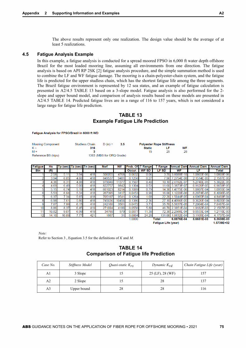
The above results represent only one realization. The design value should be the average of atleast 5 realizations.
4.5 Fatigue Analysis ExampleIn this example, a fatigue analysis is conducted for a spread moored FPSO in 6,000 ft water depth offshoreBrazil for the most loaded mooring line, assuming all environments from one direction. The fatigueanalysis is based on API RP 2SK [2] fatigue analysis procedure, and the simple summation method is usedto combine the LF and WF fatigue damage. The mooring is a chain-polyester-chain system, and the fatiguelife is predicted for the upper studless chain, which has the shortest fatigue life among the three segments.The Brazil fatigue environment is represented by 12 sea states, and an example of fatigue calculation ispresented in A2/4.5 TABLE 13 based on a 3-slope model. Fatigue analysis is also performed for the 2-slope and upper bound model, and comparison of analysis results based on these models are presented inA2/4.5 TABLE 14. Predicted fatigue lives are in a range of 116 to 157 years, which is not considered alarge range for fatigue life prediction.
TABLE 13Example Fatigue Life Prediction
Note:Refer to Section 3 , Equation 3.5 for the definitions of K and M.
TABLE 14Comparison of Fatigue life Prediction
Case No. Stiffness Model Quasi-static Krs Dynamic Krd Chain Fatigue Life (year)
A1 3 Slope 15 25 (LF), 28 (WF) 157
A2 2 Slope 15 28 137
A3 Upper bound 28 28 116
Appendix 2 Supporting Information and Examples A2
ABS GUIDANCE NOTES ON THE APPLICATION OF FIBER ROPE FOR OFFSHORE MOORING • 2021 75

5 HMPE Mooring Analysis Example
5.1 HMPE Creep Analysis ExampleA creep analysis is performed for an HMPE mooring based on the following assumptions:
i) The analysis is performed for the most loaded line assuming all the environments coming fromone direction (For more accurate analysis, the procedure in 4/2.3.1 should be used).
ii) The annual environment can be represented by 10 weather bins as shown in A2/5.1 TABLE 15
iii) The creep rate at 20°C can, for example, be represented by the following equation, which is basedon curve fitting to data presented in [18]:Rc = 4 × 10⁻¹¹ × Tm4 . 54whereRc = creep rate (1/day)Tm = mean tension (%MBS)
The analysis results are presented in A2/5.1 TABLE 15, which indicates:
● The annual creep strain is 0.44%
● The total creep strain for a design service life of 20 years is 8.8%
● Three low weather bins (2, 3, and 4) contribute to about 65% of the total creep strain
TABLE 15 Creep Analysis Results
5.2 HMPE Creep Rupture Analysis ExampleA creep rupture analysis is performed for an HMPE mooring based on the following assumptions:
i) The analysis is performed for the most loaded line assuming all the environments coming fromone direction (For more accurate analysis, the procedure in 4/2.4.1 should be used).
ii) The annual environment can be represented by 10 weather bins as shown in A2/5.2 TABLE 16
iii) The creep rupture time at 25°C can, for example, be represented by the following equation, whichis based on curve fitting to data presented in [18]:
Appendix 2 Supporting Information and Examples A2
ABS GUIDANCE NOTES ON THE APPLICATION OF FIBER ROPE FOR OFFSHORE MOORING • 2021 76

Tr = 2 × 10¹² × Tm−6 . 25whereTr = creep rupture time (day)Tm = mean tension (%MBS)
The analysis results are presented in A2/5.2 TABLE 16, which indicates:
● The annual creep rupture damage is 0.0076
● The predicted creep rupture life is 1/0.0076 = 132 years
● Four low weather bins (2, 3, 4 and 5) contribute to about 68% of the creep rupture damage
TABLE 16 Creep Rupture Analysis Results
5.3 Example of HMPE Quasi-Static StiffnessAn HMPE rope has a static stiffness of 45 MBS, and a creep rate of 0.0117% per hour at a load of 54%MBS at 20°C, the quasi-static stiffness as a function of storm duration is presented in A2/5.3 FIGURE 5. Itcan be seen that the quasi-static stiffness decreases rapidly with increasing storm duration at this load leveland temperature.
Appendix 2 Supporting Information and Examples A2
ABS GUIDANCE NOTES ON THE APPLICATION OF FIBER ROPE FOR OFFSHORE MOORING • 2021 77

FIGURE 5 Example Quasi-Static Stiffness for HMPE
6 Guidance for Dynamic Stiffness Test MatrixA dynamic stiffness test matrix for general application is provided in 8/5.4. If a project specific dynamicstiffness testing program is desired, the following guidance can be used.
i) The test matrix should include variation in loading period, mean tension, and tension range.
ii) The wave frequency period should be in the range of 12 to 35 seconds.
iii) The low frequency period should be close to the natural period of the moored floating unit.
iv) Several levels of mean tension and associated tension amplitude should be selected to represent areasonable range of storm environments. The tension amplitude in the test is the maximum tensionamplitude in the analysis, and tension range can be taken as tension amplitude times 2.
v) If VIM (vortex induced motion) under high current may occur, the matrix should include casesrepresenting VIM loadings. VIM may occur for Spar and deep draft semisubmersible hull formsand may have different amplitude to mean tension ratio from storm conditions. For example VIMloading for Spar typically has high mean tension and low tension amplitude.
vi) The number of data should be sufficient for multiple regression analysis to obtain dynamicstiffness coefficients.
vii) The maximum tension in the test should be less than 75% MBS.
viii) The ratio Tamp/Tmean should have significant variation to yield good results from regression analysis.
Appendix 2 Supporting Information and Examples A2
ABS GUIDANCE NOTES ON THE APPLICATION OF FIBER ROPE FOR OFFSHORE MOORING • 2021 78

A P P E N D I X 3 Alternative Procedure to Determine MBS
1 GeneralFor ropes of parallel construction with MBS greater than 2000 MT, a procedure for a combination ofsubrope and full rope tests can be considered, as illustrated in the following examples. This procedureshould be used only when serious limitations such as unavailability of large test machine are encountered.ABS has not developed detailed test specification and specific acceptance criteria for this procedure, andonly general guidance is provided in this Appendix. Should situation dictate that this procedure must beused, detailed testing specifications should be developed based on the principles provided here or othervalid principles. Also documentation supporting the reliability of the testing and data analysis proceduresshould be submitted in a timely manner to allow review well in advance of their implementation.
2 Example 1 - Fixed Number of SubropesThe rope is made up of a fixed number of subropes, and the subrope size changes as the full rope sizechanges (Method A in 8/2.4).
2.1 Assumption:A rope has an MBS of 2600 MT and the test machine can only test ropes to 2000 MT. The rope has Nsubropes.
2.2 Procedure:1) Conduct subrope and full rope break tests for ropes of the same design. The minimum number of
tests is shown in A3/2.2.1 TABLE 1. Let:Lf = break load of full ropeLs = average break load of the subropes (minimum 4 tests)N = number of subropes in full rope
Conversion factor F = Lf/ NLs (A3.1)TABLE 1
Alternative Method A to Determine MBS
Rope No. MBS (MT) No. of FullRope Test
No. of SubropeTest
ConversionFactor F
Method for F
1 1,300 2 4 F 1 (2) Tested
2 1,700 3 4 F 2 (3) Tested
3 2,000 4 4 F 3 (4) Tested
4 (Target) 2,600 0 4 F 4 Estimated
Total 9 16
Note that MBS for rope No. 1 and No. 3 should be greater than 50% and 75% of the target MBS, respectively.MBS for rope No. 2 should be close to the average MBS of rope No. 1 and No. 3.
ABS GUIDANCE NOTES ON THE APPLICATION OF FIBER ROPE FOR OFFSHORE MOORING • 2021 79

2) Conduct regression analysis for the conversion factors F1, F2 and F3 (total 9) and determine F4based on evaluation of test data and the statistical values (mean, mean minus SD, mean minus2SD) from the regression analysis for all rope samples.
3) The estimated break load for the target rope is:Lf = F4 × N × Ls (A3.2)The MBS will be accepted if the estimated break load is greater than the MBS.
4) This method applies only to ropes with same design parameters:
● Number of subropes
● Sub-rope construction
● Yarn type
● Number of layers in eye configuration
● D/d ratio for hardware
● Shape of hardware bearing surface
● Splice lengths (Number of strand tucks and tapered tucks)
● Chafe protection material and application in the eye
3 Example 2 - Fixed Size of SubropeThe rope is made up with subropes of the same size, and the number of subrope changes as the full ropesize changes (Method B in 8/2.4).
3.1 Assumption:A rope has an MBS of 2600 MT and the test machine can only test ropes to 2000 MT. The rope has 26subropes (N= 26).
3.2 Procedure:1) Conduct subrope and full rope break tests for ropes of the same design. The minimum number of
tests is shown in A3/3.2.1 TABLE 2 (refer to Equation A3.1).
TABLE 2Alternative Method B to Determine MBS
Rope No. MBS (MT) N No. of FullRope Test
No. ofSubrope Test
ConversionFactor F
Method for F
1 13 2 F 1 (2) Tested
2 17 3 F 2 (3) Tested
3 20 4 F 3 (4) Tested
4 (Target) 2,600 26 0 4 F 4 Estimated
Total 9 4
Note that number of subropes for rope No. 1 and No. 3 should be greater than 50% and 75% of that for the targetrope, respectively. Number of subropes for rope No. 2 should be close to the average number of subropes of ropeNo. 1 and No. 3.
Appendix 3 Alternative Procedure to Determine MBS A3
ABS GUIDANCE NOTES ON THE APPLICATION OF FIBER ROPE FOR OFFSHORE MOORING • 2021 80

2) Conduct regression analysis for the conversion factors F1, F2 and F3 (total 9) and determine F4based on evaluation of test data and the statistical values (mean, mean minus SD, mean minus2SD) from the regression analysis for all rope samples.
3) The estimated break load for the target rope is:Lf = F4 × 26 × Ls (A3.3)The MBS will be accepted if the estimated break load is greater than the MBS.
4) This method applies only to ropes with same subrope and full rope design parameters as indicatedbelow:
Subrope parameters
● MBS
● Subrope construction
● Yarn type
Full rope parameters
● D/d ratio for hardware
● Shape of hardware bearing surface
● Splice length (Number of strand tucks and tapered tucks)
● Chafe protection material and application in the eye
Appendix 3 Alternative Procedure to Determine MBS A3
ABS GUIDANCE NOTES ON THE APPLICATION OF FIBER ROPE FOR OFFSHORE MOORING • 2021 81