Embed Size (px)
Citation preview

Guide for installers
METTLER TOLEDO MultiRangeSystem solution analog Ex1
Hazardous area Safe area


Contents
Guide for installers 22012215 04/09 1
System solution analog Ex1
Contents Page
1 Safety precautions ....................................................................... 2
2 System overview ......................................................................... 32.1 Using the System solution analog Ex1............................................. 32.2 Typical configurations ................................................................... 32.3 Description of components ............................................................ 3
3 Installation.................................................................................. 43.1 Setting up System solution analog Ex1............................................ 43.2 Equipotential bonding ................................................................... 53.3 Connecting power supply .............................................................. 63.4 Configuration ............................................................................... 63.5 Corner adjustment ........................................................................ 6
4 Replacing connection cables ........................................................ 84.1 Making connection cables ............................................................. 84.2 Installing new connection cable...................................................... 9
5 Technical data ............................................................................. 105.1 General technical data................................................................... 105.2 Intrinsically safe characteristic values.............................................. 115.3 Dimensional drawing .................................................................... 11
6 Accessories................................................................................. 12

Safety precautions
2 Guide for installers 22012215 04/09
System solution analog Ex1
1 Safety precautions
The System solution analog Ex1 is approved for operation in Zone 1 and 21hazardous areas.Particular care is required when using weighing systems with the System solutionanalog Ex1 in hazardous areas. The code of practice is oriented to the "SafeDistribution" concept drawn up by METTLER TOLEDO.
Competence The System solution analog Ex1 may only be installed, maintained and repairedby authorised METTLER TOLEDO service personnel.
Ex approval No modifications may be made to the device and no repair work may be performedon the modules. Any weighing cells or system modules that are used must complywith the specifications contained in the installation instructions. Non-compliantequipment jeopardises the intrinsic safety of the system, cancels the "Ex" approvaland renders any warranty or product liability claims null and void.
The safety of the weighing system is only guaranteed when the weighing systemis operated, installed and maintained in accordance with the respective instructions.
Also comply with the following: – the instructions for the system modules and weighing cells,– the regulations and standards in the respective country,– the statutory requirement for electrical equipment installed in hazardous areas
in the respective country,– all instructions related to safety issued by the owner.
The explosion-protected weighing system must be checked to ensure compliancewith the requirements for safety before being put into service for the first time,following any service work and every 3 years, at least.
Operation Prevent the build-up of static electricity. Always wear suitable working clotheswhen operating or performing service work in an hazardous area.
Do not use protective coverings for the devices.
Avoid damage to the system components.
Installation Only install or perform maintenance work on the weighing system in thehazardous areas if the following conditions are fulfilled:– the intrinsically safe characteristic values and zone approval of the individual
components are in accord with one another,– the owner has issued a permit ("spark permit" or "fire permit"),– the area has been rendered safe and the owner's safety co-ordinator has
confirmed that there is no danger,– the necessary tools and any required protective clothing are provided (danger
of the build-up of static electricity).
The certification papers (certificates, manufacturer’s declarations) must be present.
Lay cabling securely so that it does not move and effectively protect it againstdamage.
Only route cables into the housing of the system modules via the suitable cablegland and ensure proper seating of the seals.

System overview
Guide for installers 22012215 04/09 3
System solution analog Ex1
2 System overview
2.1 Using the System solution analog Ex1The System solution analog Ex1 is used to connect intrinsically safe analog weighingcells to a weighing terminal with an integrated A/D converter.Here, the System solution analog Ex1 adds up the analog voltage signals of theindividual weighing cells.With the System solution analog Ex1, it is possible to construct special scales, e.g.container scales consisting of several DMS weighing cells with a container placed ontop.
2.2 Typical configurations
2.2.1 System solution analog Ex1, intrinsically safe weighing terminal and DMS weighing cells
* Weighing cells must be approved for the hazardous area. The intrinsically safe characteristic values must be in accord with those of the A/Dconverter of the weighing terminal.
2.3 Description of components System solution
analog Ex1Ignition protection type EN II 2G EEx ia IIC T4
II 2D IP68 T75°CTemperature range –20 °C to +60 °CProtection type IP68Connection cable 5 m
Weighing cell 1*
Ex-i,max. 20 m
System solutionanalog Ex1
Weighing cell 2*
Weighing cell 3*
Weighing cell 4*
Weighingterminal
Hazardous area Safe area

Installation
4 Guide for installers 22012215 04/09
System solution analog Ex1
3 Installation
3.1 Setting up System solution analog Ex1
3.1.1 Preparing System solution analog Ex1
1. Open cover of the System solution analog Ex1 by loosening the 12 screws.
2. Remove blind plugs for connection of the weighing cell cables.
3.1.2 Connecting DMS weighing cells
CAUTION
Weighing cell cables may not be shortened!
Preparing cell cable
1. Strip cable end approx. 180 mm.
2. Shorten cable shielding to 6 mm.
3. Strip the wire ends approx. 6 mm and twist them.
4. Push on the wire end ferrules and press them on firmly with a pair of crimpingpliers.
Attaching cable gland tocell cable
NoteMeasures for shielding against incoming and outgoing interference are especiallyimportant with longer cell cables. The maximum interference immunity classes willonly be achieved with careful and proper installation and wiring of all connectedperipherals and weighing platforms.For this purpose, it is extremely important to connect the shielding on both sides in aprofessional manner.The CE-conformity of the entire system is the responsibility of the personcommissioning the device.
1. Slide the union nut and moulded seal over the prepared cable.
2. Place cable shielding over the contact.
3. Screw in metal housing with union nut.
180
6 6
Installation
Guide for installers 22012215 04/09 5
System solution analog Ex1
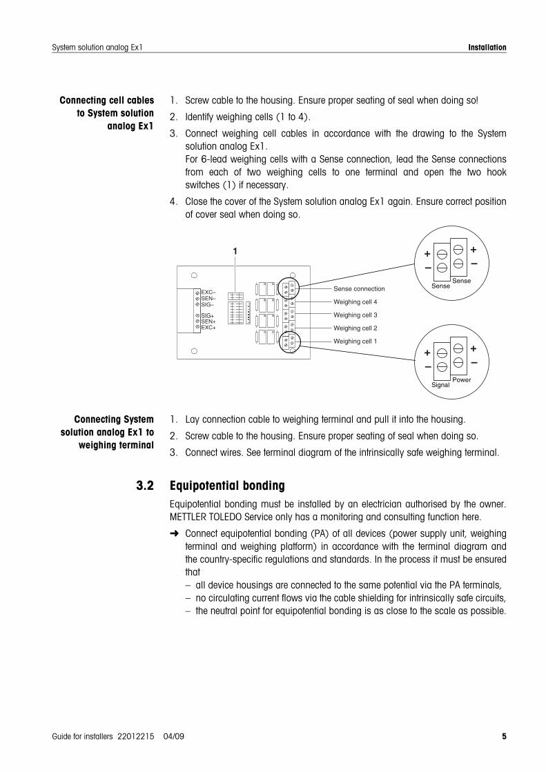
Connecting cell cablesto System solution
analog Ex1
1. Screw cable to the housing. Ensure proper seating of seal when doing so!
2. Identify weighing cells (1 to 4).
3. Connect weighing cell cables in accordance with the drawing to the Systemsolution analog Ex1.For 6-lead weighing cells with a Sense connection, lead the Sense connectionsfrom each of two weighing cells to one terminal and open the two hookswitches (1) if necessary.
4. Close the cover of the System solution analog Ex1 again. Ensure correct positionof cover seal when doing so.
Connecting Systemsolution analog Ex1 to
weighing terminal
1. Lay connection cable to weighing terminal and pull it into the housing.
2. Screw cable to the housing. Ensure proper seating of seal when doing so.
3. Connect wires. See terminal diagram of the intrinsically safe weighing terminal.
3.2 Equipotential bondingEquipotential bonding must be installed by an electrician authorised by the owner.METTLER TOLEDO Service only has a monitoring and consulting function here.
Connect equipotential bonding (PA) of all devices (power supply unit, weighingterminal and weighing platform) in accordance with the terminal diagram andthe country-specific regulations and standards. In the process it must be ensuredthat– all device housings are connected to the same potential via the PA terminals,– no circulating current flows via the cable shielding for intrinsically safe circuits,– the neutral point for equipotential bonding is as close to the scale as possible.
Weighing cell 4
Weighing cell 3
Weighing cell 2
Weighing cell 1
Sense connection
PowerSignal
+–
+–
EXC–SEN–SIG–
EXC+SEN+SIG+
SenseSense
+–
+–
1

Installation
6 Guide for installers 22012215 04/09
System solution analog Ex1
3.3 Connecting power supplySee guide for installers of the intrinsically safe weighing terminal or power supply.
3.4 ConfigurationConfiguration of the weighing system occurs via service mode of the A/D converter ofthe connected weighing terminal. See operating instructions of the weighing terminal.
3.5 Corner adjustmentCorner compensation must be performed after configuration and calibration of theweighing system.
3.5.1 Checking cornerloadChecking of a multi-sensor weighing platform with four weighing cells is described inthe following.
1. Place the test weight (1/3 of maximum load) in the centre of the load plate andtare.
2. Load test weights in succession in the middle of each of the four quadrants, andnote absolute value with sign.
Adjustment is required for deviations greater than the permissible verification errorlimit.
3.5.2 Adjusting corners
Notes
• Begin the adjustment at the corner with the greatest deviation.
• The adjustment of weighing cell 1 occurs at the potentiometer pair 1, cell 2 atpair 2, etc.
Potentiometer pair 4
Potentiometer pair 3
Potentiometer pair 2
Potentiometer pair 1
Weighing cell 4
Weighing cell 3
Weighing cell 2
Weighing cell 1
Hook switches

Installation
Guide for installers 22012215 04/09 7
System solution analog Ex1
1. Switch off weighing system.
2. Open all hook switches.
3. Move all potentiometers to the middle position.
4. With a positive deviation: Turn both potentiometers the same number of rotationsto the right.With a negative deviation: Turn both potentiometers the same number ofrotations to the left.
5. After completing corner adjustment, screw the cover of the system solution backon. Ensure proper seating of seal when doing so.
NotesThe following work must be performed after a weighing cell has been replaced:
• Recalibrate weighing system with maximum load.
• Check cornerload and adjust if need be.

Replacing connection cables
8 Guide for installers 22012215 04/09
System solution analog Ex1
4 Replacing connection cables
4.1 Making connection cables
EXPLOSION HAZARD
Take the parameters of the cable used into consideration when checking theintrinsically safe parameters.
Use only cables approved for use in the hazardous area.
Customer-specific weighing platform cables for intrinsically safe circuits must befabricated as follows:
1. Cut cable to length and strip cable ends according to dimension A/B.
2. Shorten shielding on both sides to 10 mm.
3. Strip wire ends.
4. Crimp wire end ferrules onto wire ends with a crimping tool.
5. Push second rear section of earthing cable gland onto cable. Do not damage theinsulation of the wires here.
6. Push sleeve over wires and shield. Fold over cable shielding.
7. Push on front section of cable gland and screw onto rear section.
CableDimension A (system solution)
Dimension B(terminal)
Max. length
System solution analog Ex1 – weighing terminal
3 x 2 x 0.75 mm2 80 mm1 215 mm1 100 m1
A B
Earthing cable gland
Cable shielding
Push sleeve over wires and shielding
As per country-specific regulations for intrinsically-safe circuits
Wire end ferruleswith plastic collar,crimp connection
Replacing connection cables
Guide for installers 22012215 04/09 9
System solution analog Ex1
4.2 Installing new connection cable1. Open System solution analog Ex1 and detach preinstalled connection cable from
the junction PCB.
2. Disconnect earthing cable gland and pull out cable.
3. Pull newly made connection cable into the terminal box and secure with theearthing cable gland. Ensure correct position of seal when doing so.
4. Attach wires according to labelling at the junction PCB.
5. Close housing cover of the System solution analog Ex1. Ensure correct positionof seal when doing so.
6. Lay connection cable securely to weighing terminal and connect according to theguide for installers.
Technical data
10 Guide for installers 22012215 04/09
System solution analog Ex1
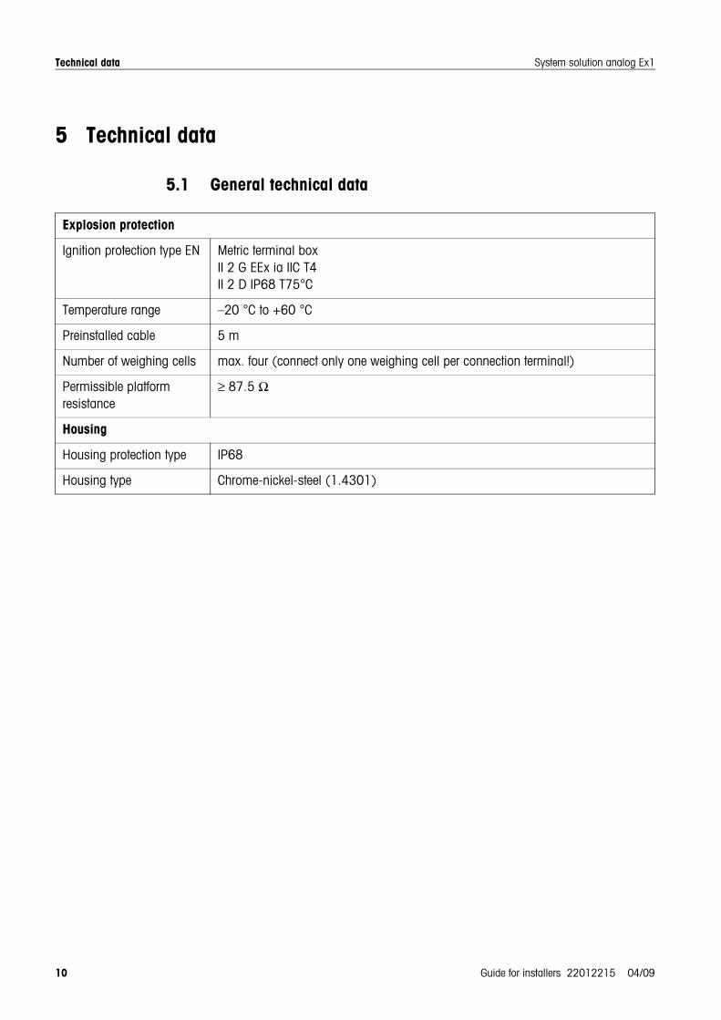
5 Technical data
5.1 General technical data
Explosion protection
Ignition protection type EN Metric terminal boxII 2 G EEx ia IIC T4II 2 D IP68 T75°C
Temperature range –20 °C to +60 °C
Preinstalled cable 5 m
Number of weighing cells max. four (connect only one weighing cell per connection terminal!)
Permissible platform resistance
≥ 87.5 Ω
Housing
Housing protection type IP68
Housing type Chrome-nickel-steel (1.4301)

Technical data
Guide for installers 22012215 04/09 11
System solution analog Ex1
5.2 Intrinsically safe characteristic values
Power supply and measurement circuit
CAUTIONThe following conditions must be fulfilled before you connect the System solutionanalog Ex1 to the A/D converter of the weighing terminal:
• Ui, cell > U0, A/D converter
Ii, cell > I0, A/D converter
Pi, cell > P0, A/D converter
n x Ci, cell + Ccable < C0, A/D converter (n = number of connected cells)Li, cell + Lcable < L0, A/D converter
• Ui max, system solution > U0, A/D converter
Ii max, system solution > I0, A/D converter
Pi max, system solution > P0, A/D converter
The weighing cell cable and connection cable of the System solution analog Ex1must be taken into account here when calculating the inductivities and capacitances.
5.3 Dimensional drawing
Metric terminal box
Ui max Ii max Pi max
KL5, KL6, KL7 20 V 350 mA 1.2 W
84
315
44
350
320
50
Dim. in mm

Accessories
12 Guide for installers 22012215 04/09
System solution analog Ex1
6 Accessories
Graphic Designation Order No.
Cable
For intrinsically safe circuits, Ex-i 3 x 2 x 0.75 mm2,shielded, 100 m
00 504 638
Wire end ferrulesH 0.75 / 13, with plastic collar, 100 pcs.
00 504 639
Cable glandM16 x 1.5 EEx e II, 6 pcs.
22 006 708


22012215
Subject to technical changes © Mettler-Toledo (Albstadt) GmbH 04/09 Printed in Germany 22012215
Mettler-Toledo (Albstadt) GmbHD-72458 AlbstadtTel. ++49-7431-14 0, Fax ++49-7431-14 232Internet: http://www.mt.com