Embed Size (px)
Citation preview

1
INSTALLATION GUIDEGuide for your 2-Pole, Single-Axis Solar Tracker
Congratulations, you have purchased the finest solar tracker available. With proper installation, your tracker willprovide years of trouble-free service while maximizing your solar power production.
Your tracker may include one of the following options: (Check your packing slip.):
♦ Stainless Steel Hardware Option - Recommended for high humidity and salt laden environments.
♦ Wattsun Voltage Converter Option - Required for PV Systems other than 24 VDC.
♦ Manual Control Option - Exterior switches so you may manually operate the tracker.
The tracker comes complete with all the hardware necessary for assembly and mounting the PV modules. TheWattsun™ Tracker requires a length of Schedule 40 steel pipe for use as the pipe mast. Specifications for thepipe mast can be found on the data sheet for this particular tracker. The steel pipe and all array wiring,additional fusing, disconnects and electrical junction boxes, etc. must be provided by your electrician orinstaller.
WARNING:
If the Wattsun™ Azimuth Solar Tracker is not installed to manufacturer’s specifications, suchfailure to properly install unit may cause tracker malfunction and or serious bodily injury ordeath. This tracker moves, therefore the tracker should be situated away from anybody oranything that may come in contact with it as it moves.
KEEP CHILDREN AWAY FROM TRACKER AT ALL TIMES.
Array Technologies, Inc.3312 Stanford NEAlbuquerque, NM 87107
Tel: 505-881-7567Fax: 505-881-7572
URL: www.wattsun.com
2
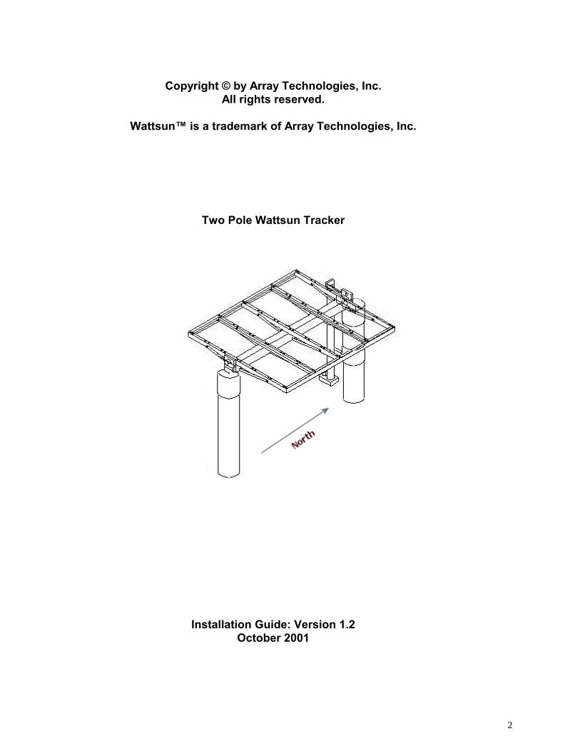
Copyright © by Array Technologies, Inc.All rights reserved.
Wattsun™ is a trademark of Array Technologies, Inc.
Two Pole Wattsun Tracker
Installation Guide: Version 1.2October 2001
3
WARNING TO ELECTRICIAN OR INSTALLER
♦ Please read this instruction manual completely.
♦ If you are unfamiliar with NEC compliant solar electric installation, thenconsult with the dealer that supplied your tracker. They should have theskill and expertise to supply you with the necessary wiring diagrams and theappropriate connection wire, grounding equipment, junction boxes and fusing.
♦ Failure to ground the array structure, including each module frame, thealuminum tracker frame, the drive head assembly and the pipe mast maymake the tracker susceptible to damage by lightning.
♦ Do not rely on the pipe masts to act as a ground rod. They are not areliable substitute for a properly installed ground rod.
♦ Please send in the Wattsun Tracker Warranty Card. Array Technologiesdoes not share any of the information provided on the warranty card.
♦ Please leave this manual for the tracker owner(s). It is their property andwill help resolve any potential problems.
♦ Please provide the following information for the owner:
Serial Numbers: __________________________________ ______________________________________ Serial Number located on the controller Serial Number located on the drive assembly
Tracker Type Single-Axis Tracker Dual-Axis Tracker
Controller is powered from: Battery Bank Array-Direct
System Type: Off-Grid/Remote Home Grid-Intertie - no battery backup Grid-Intertie - battery backupWater Pumping Other _____________________
PV Array: PV System Voltage is ______ VDC Number of Modules: __________
Module Manufacturer: ____________ Module Model: ____________
Mounting Pole Height above the Ground is: ________ FT
4
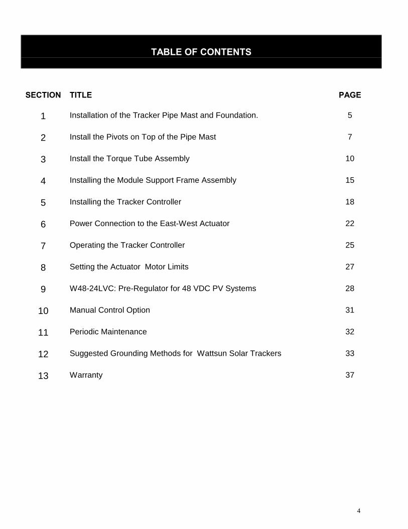
TABLE OF CONTENTS
SECTION TITLE PAGE
1 Installation of the Tracker Pipe Mast and Foundation. 5
2 Install the Pivots on Top of the Pipe Mast 7
3 Install the Torque Tube Assembly 10
4 Installing the Module Support Frame Assembly 15
5 Installing the Tracker Controller 18
6 Power Connection to the East-West Actuator 22
7 Operating the Tracker Controller 25
8 Setting the Actuator Motor Limits 27
9 W48-24LVC: Pre-Regulator for 48 VDC PV Systems 28
10 Manual Control Option 31
11 Periodic Maintenance 32
12 Suggested Grounding Methods for Wattsun Solar Trackers 33
13 Warranty 37
5
Section 1 Installation of tracker pipe mast and foundation
WARNING! WINDY CONDITIONS CAN EXERT EXTREME FORCES ON THE ARRAY, FOUNDATION,AND PIPE MASTS OF YOUR TRACKER.
1.1) Choose an optimum solar location to install the PV array for in the ground mounting. The location shouldbe free from obstructions. Keep in mind that over a period of time, that trees, shrubs, etc. may grow enoughto obscure the PV array from the sun. Consult with your dealer for proper tracker spacing and alignmentregarding multiple tracker installations.
1.2) Dig an appropriate sized hole for your tracker’s foundation using a shovel, auger, or backhoe. The variablesthat affect the design of the foundation include: tracker size, pipe mast height, soil conditions, geographicallocation, weather and local building codes. Employ a qualified professional to design the foundation for yourtracker.
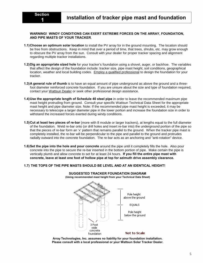
1.3) A general rule of thumb is to have an equal amount of pipe underground as above the ground and a three-foot diameter reinforced concrete foundation. If you are unsure about the size and type of foundation required,contact your Wattsun Dealer or seek other professional design assistance.
1.4) Use the appropriate length of Schedule 40 steel pipe in order to leave the recommended maximum pipemast height protruding from ground. Consult your specific Wattsun Technical Data Sheet for the appropriatemast height and pipe diameter size. Note: If the recommended pipe mast height is exceeded, it may benecessary to telescope a larger diameter pipe in the lower portion and increase the foundation size in order towithstand the increased forces exerted during windy conditions.
1.5) Cut at least two pieces of re-bar (more with 8 module or larger trackers), at lengths equal to the full diameterof the foundation. Weld re-bar onto (or drill holes and insert re-bar into) the underground portion of the pipe sothat the pieces of re-bar form an ‘x’ pattern that remains parallel to the ground. When the tracker pipe mast iscompletely installed, the re-bar will be perpendicular to the pipe and parallel to the ground and protrudesradially outward into the concrete foundation. The re-bar acts as an anchoring and "anti-rotation" device.
1.6) Set the pipe into the hole and pour concrete around the pipe until it completely fills the hole. Also pourconcrete into the pipe to secure the re-bar inserted in the bottom portion of pipe. Make certain the pipe isvertically plumb and allow concrete to set for at least 24 hours. If you fill the entire pipe mast withconcrete, leave at least one foot of hollow pipe at top for azimuth drive assembly clearance.
1.7) THE TOPS OF THE PIPE MASTS SHOULD BE LEVEL AND AT AN IDENTICAL HEIGHT!
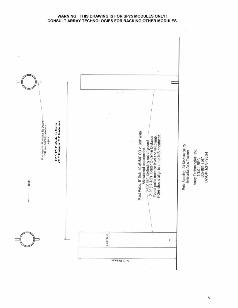
SUGGESTED TRACKER FOUNDATION DIAGRAM(Using recommended mast height from your Technical Data Sheet)
Array Technologies, Inc. assumes no liability for your foundation installation.Please consult with a local professional or your Wattsun Solar Tracker Dealer.
6
WARNING! THIS DRAWING IS FOR SP75 MODULES ONLY!CONSULT ARRAY TECHNOLOGIES FOR RACKING OTHER MODULES

7
Section2 Install the Pivots on Top of the Pipe Masts
Note: Actuator Placement can vary depending on your application!
2.1) Northern or Southern Hemisphere installations.
For Northern Hemisphere installations, point the actuator end of the tracker to ‘true north’ * and tightenthe four set bolts to secure tracker to pipe mast. The set bolts should be on the East Side and tightened sothat they dig into the pipe mast.
For Southern Hemisphere locations, point the actuator end of the tracker to ‘true south’ * and tighten thefour set bolts to secure tracker to pipe mast. The set bolts should be on the West Side and tightened so thatthey dig into the pipe mast. Reverse the East-West and North-South references that follow in this guide.
* Note:True north and south differ from magnetic north and south and depends on geographical location. Locate‘magnetic north’ or ‘magnetic south’ using a compass and adjust your tracker setting accordingly. Your WattsunTracker Dealer can provide you with the Magnetic Declination for your area. The Array Technologies web site(www.wattsun.com) has links to geomagnetic data. You can find, or calculate, the magnetic declination for anyplace on the globe.
Perhaps the easiest way to find the North-South line is to get a copy of your local newspaper and find theSunrise and Sunset times. Determine the time (hour and minute) that falls exactly halfway between Sunriseand Sunset. At the halfway or 'Solar Noon' point, anything that casts a shadow will do so along a North-Southline. Get a friend to help hold up a length of wood or a stick of conduit straight up into the sky. Then stake outor mark the North-South shadow line.
8
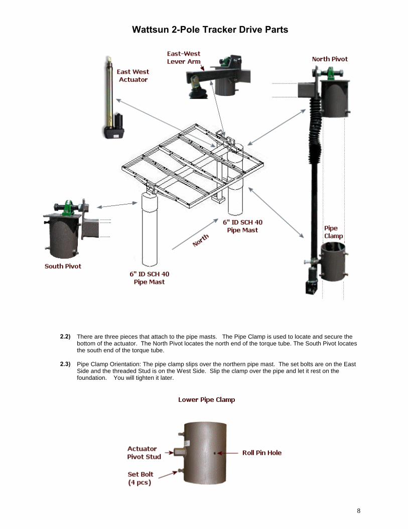
Wattsun 2-Pole Tracker Drive Parts
2.2) There are three pieces that attach to the pipe masts. The Pipe Clamp is used to locate and secure thebottom of the actuator. The North Pivot locates the north end of the torque tube. The South Pivot locatesthe south end of the torque tube.
2.3) Pipe Clamp Orientation: The pipe clamp slips over the northern pipe mast. The set bolts are on the EastSide and the threaded Stud is on the West Side. Slip the clamp over the pipe and let it rest on thefoundation. You will tighten it later.
9
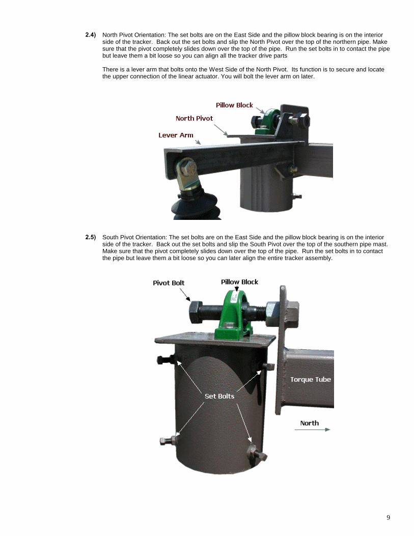
2.4) North Pivot Orientation: The set bolts are on the East Side and the pillow block bearing is on the interiorside of the tracker. Back out the set bolts and slip the North Pivot over the top of the northern pipe. Makesure that the pivot completely slides down over the top of the pipe. Run the set bolts in to contact the pipebut leave them a bit loose so you can align all the tracker drive parts
There is a lever arm that bolts onto the West Side of the North Pivot. Its function is to secure and locatethe upper connection of the linear actuator. You will bolt the lever arm on later.
2.5) South Pivot Orientation: The set bolts are on the East Side and the pillow block bearing is on the interiorside of the tracker. Back out the set bolts and slip the South Pivot over the top of the southern pipe mast.Make sure that the pivot completely slides down over the top of the pipe. Run the set bolts in to contactthe pipe but leave them a bit loose so you can later align the entire tracker assembly.
10
Section3 Install the Torque Tube Assembly
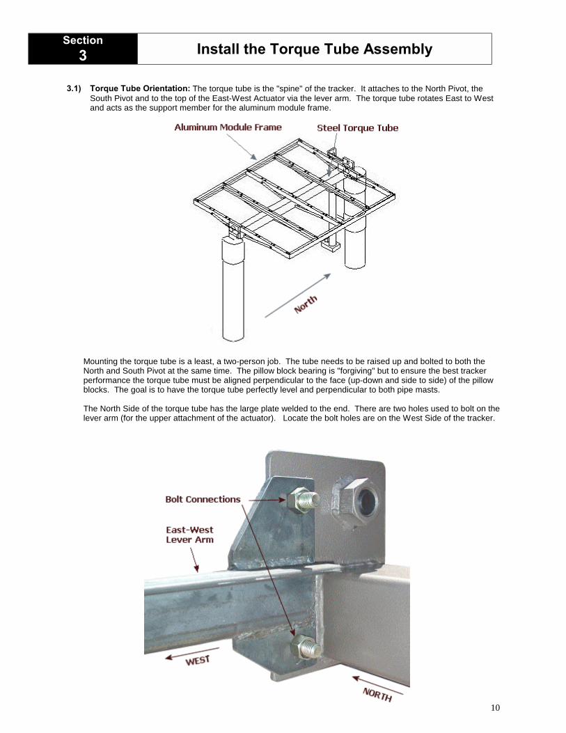
3.1) Torque Tube Orientation: The torque tube is the "spine" of the tracker. It attaches to the North Pivot, theSouth Pivot and to the top of the East-West Actuator via the lever arm. The torque tube rotates East to Westand acts as the support member for the aluminum module frame.
Mounting the torque tube is a least, a two-person job. The tube needs to be raised up and bolted to both theNorth and South Pivot at the same time. The pillow block bearing is "forgiving" but to ensure the best trackerperformance the torque tube must be aligned perpendicular to the face (up-down and side to side) of the pillowblocks. The goal is to have the torque tube perfectly level and perpendicular to both pipe masts.
The North Side of the torque tube has the large plate welded to the end. There are two holes used to bolt on thelever arm (for the upper attachment of the actuator). Locate the bolt holes are on the West Side of the tracker.
11
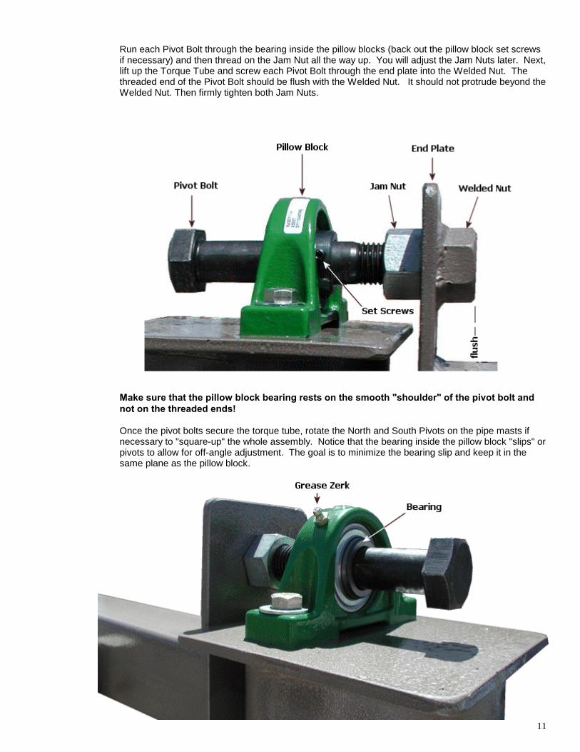
Run each Pivot Bolt through the bearing inside the pillow blocks (back out the pillow block set screwsif necessary) and then thread on the Jam Nut all the way up. You will adjust the Jam Nuts later. Next,lift up the Torque Tube and screw each Pivot Bolt through the end plate into the Welded Nut. Thethreaded end of the Pivot Bolt should be flush with the Welded Nut. It should not protrude beyond theWelded Nut. Then firmly tighten both Jam Nuts.
Make sure that the pillow block bearing rests on the smooth "shoulder" of the pivot bolt andnot on the threaded ends!
Once the pivot bolts secure the torque tube, rotate the North and South Pivots on the pipe masts ifnecessary to "square-up" the whole assembly. Notice that the bearing inside the pillow block "slips" orpivots to allow for off-angle adjustment. The goal is to minimize the bearing slip and keep it in thesame plane as the pillow block.
12
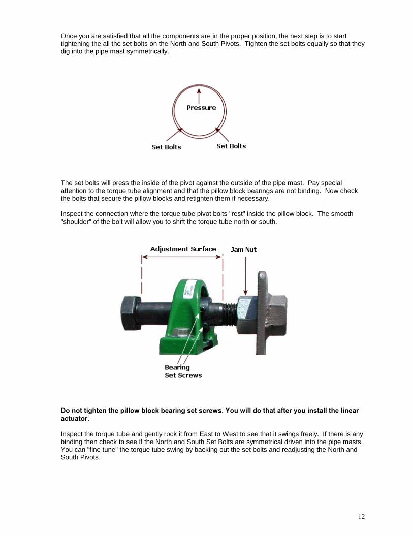
Once you are satisfied that all the components are in the proper position, the next step is to starttightening the all the set bolts on the North and South Pivots. Tighten the set bolts equally so that theydig into the pipe mast symmetrically.
The set bolts will press the inside of the pivot against the outside of the pipe mast. Pay specialattention to the torque tube alignment and that the pillow block bearings are not binding. Now checkthe bolts that secure the pillow blocks and retighten them if necessary.
Inspect the connection where the torque tube pivot bolts "rest" inside the pillow block. The smooth"shoulder" of the bolt will allow you to shift the torque tube north or south.
Do not tighten the pillow block bearing set screws. You will do that after you install the linearactuator.
Inspect the torque tube and gently rock it from East to West to see that it swings freely. If there is anybinding then check to see if the North and South Set Bolts are symmetrical driven into the pipe masts.You can "fine tune" the torque tube swing by backing out the set bolts and readjusting the North andSouth Pivots.
13
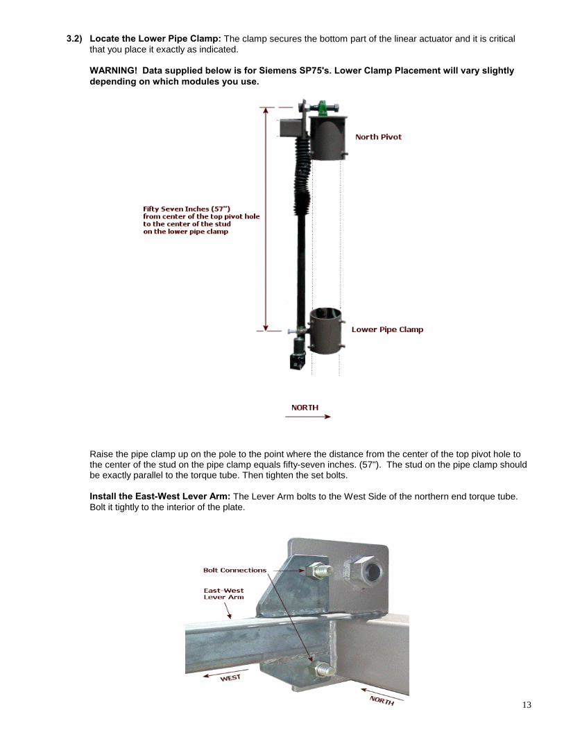
3.2) Locate the Lower Pipe Clamp: The clamp secures the bottom part of the linear actuator and it is criticalthat you place it exactly as indicated.
WARNING! Data supplied below is for Siemens SP75's. Lower Clamp Placement will vary slightlydepending on which modules you use.
Raise the pipe clamp up on the pole to the point where the distance from the center of the top pivot hole tothe center of the stud on the pipe clamp equals fifty-seven inches. (57"). The stud on the pipe clamp shouldbe exactly parallel to the torque tube. Then tighten the set bolts.
Install the East-West Lever Arm: The Lever Arm bolts to the West Side of the northern end torque tube.Bolt it tightly to the interior of the plate.
14
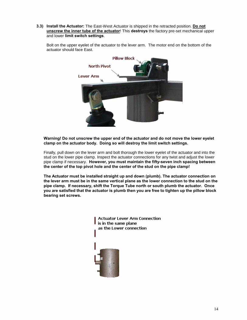
3.3) Install the Actuator: The East-West Actuator is shipped in the retracted position. Do notunscrew the inner tube of the actuator! This destroys the factory pre-set mechanical upperand lower limit switch settings.
Bolt on the upper eyelet of the actuator to the lever arm. The motor end on the bottom of theactuator should face East.
Warning! Do not unscrew the upper end of the actuator and do not move the lower eyeletclamp on the actuator body. Doing so will destroy the limit switch settings.
Finally, pull down on the lever arm and bolt thorough the lower eyelet of the actuator and into thestud on the lower pipe clamp. Inspect the actuator connections for any twist and adjust the lowerpipe clamp if necessary. However, you must maintain the fifty-seven inch spacing betweenthe center of the top pivot hole and the center of the stud on the pipe clamp!
The Actuator must be installed straight up and down (plumb). The actuator connection onthe lever arm must be in the same vertical plane as the lower connection to the stud on thepipe clamp. If necessary, shift the Torque Tube north or south plumb the actuator. Onceyou are satisfied that the actuator is plumb then you are free to tighten up the pillow blockbearing set screws.
15
Section4
Install the Module Support Frameonto the North/South Torque Tube
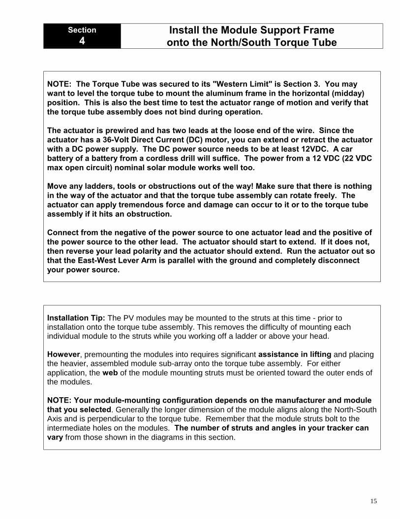
NOTE: The Torque Tube was secured to its "Western Limit" is Section 3. You maywant to level the torque tube to mount the aluminum frame in the horizontal (midday)position. This is also the best time to test the actuator range of motion and verify thatthe torque tube assembly does not bind during operation.
The actuator is prewired and has two leads at the loose end of the wire. Since theactuator has a 36-Volt Direct Current (DC) motor, you can extend or retract the actuatorwith a DC power supply. The DC power source needs to be at least 12VDC. A carbattery of a battery from a cordless drill will suffice. The power from a 12 VDC (22 VDCmax open circuit) nominal solar module works well too.
Move any ladders, tools or obstructions out of the way! Make sure that there is nothingin the way of the actuator and that the torque tube assembly can rotate freely. Theactuator can apply tremendous force and damage can occur to it or to the torque tubeassembly if it hits an obstruction.
Connect from the negative of the power source to one actuator lead and the positive ofthe power source to the other lead. The actuator should start to extend. If it does not,then reverse your lead polarity and the actuator should extend. Run the actuator out sothat the East-West Lever Arm is parallel with the ground and completely disconnectyour power source.
Installation Tip: The PV modules may be mounted to the struts at this time - prior toinstallation onto the torque tube assembly. This removes the difficulty of mounting eachindividual module to the struts while you working off a ladder or above your head.
However, premounting the modules into requires significant assistance in lifting and placingthe heavier, assembled module sub-array onto the torque tube assembly. For eitherapplication, the web of the module mounting struts must be oriented toward the outer ends ofthe modules.
NOTE: Your module-mounting configuration depends on the manufacturer and modulethat you selected. Generally the longer dimension of the module aligns along the North-SouthAxis and is perpendicular to the torque tube. Remember that the module struts bolt to theintermediate holes on the modules. The number of struts and angles in your tracker canvary from those shown in the diagrams in this section.
16
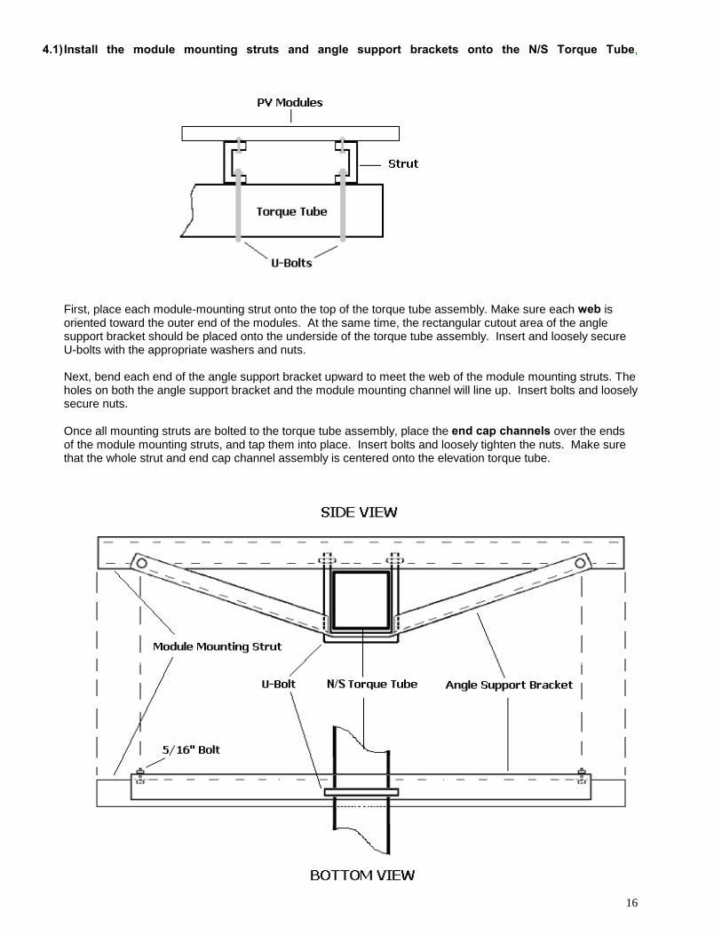
4.1) Install the module mounting struts and angle support brackets onto the N/S Torque Tube,
First, place each module-mounting strut onto the top of the torque tube assembly. Make sure each web isoriented toward the outer end of the modules. At the same time, the rectangular cutout area of the anglesupport bracket should be placed onto the underside of the torque tube assembly. Insert and loosely secureU-bolts with the appropriate washers and nuts.
Next, bend each end of the angle support bracket upward to meet the web of the module mounting struts. Theholes on both the angle support bracket and the module mounting channel will line up. Insert bolts and looselysecure nuts.
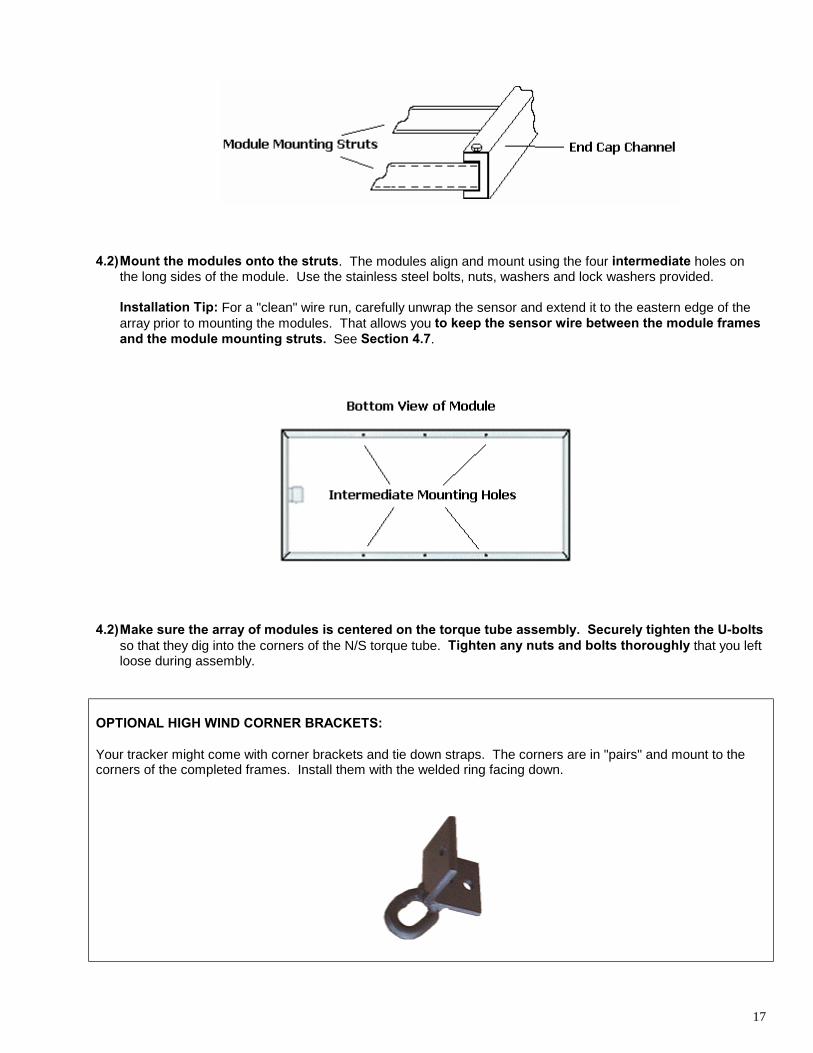
Once all mounting struts are bolted to the torque tube assembly, place the end cap channels over the endsof the module mounting struts, and tap them into place. Insert bolts and loosely tighten the nuts. Make surethat the whole strut and end cap channel assembly is centered onto the elevation torque tube.
17
4.2) Mount the modules onto the struts. The modules align and mount using the four intermediate holes onthe long sides of the module. Use the stainless steel bolts, nuts, washers and lock washers provided.
Installation Tip: For a "clean" wire run, carefully unwrap the sensor and extend it to the eastern edge of thearray prior to mounting the modules. That allows you to keep the sensor wire between the module framesand the module mounting struts. See Section 4.7.
4.2) Make sure the array of modules is centered on the torque tube assembly. Securely tighten the U-boltsso that they dig into the corners of the N/S torque tube. Tighten any nuts and bolts thoroughly that you leftloose during assembly.
OPTIONAL HIGH WIND CORNER BRACKETS:
Your tracker might come with corner brackets and tie down straps. The corners are in "pairs" and mount to thecorners of the completed frames. Install them with the welded ring facing down.
18
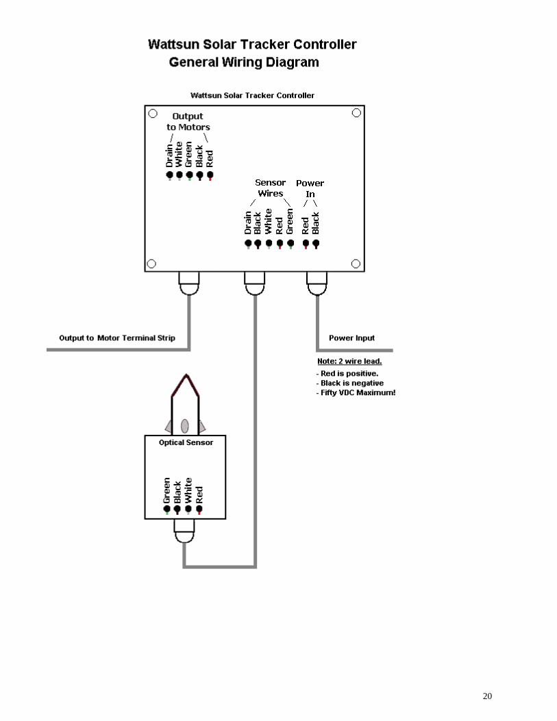
Section5 Installing the Wattsun Solar Tracker Controller
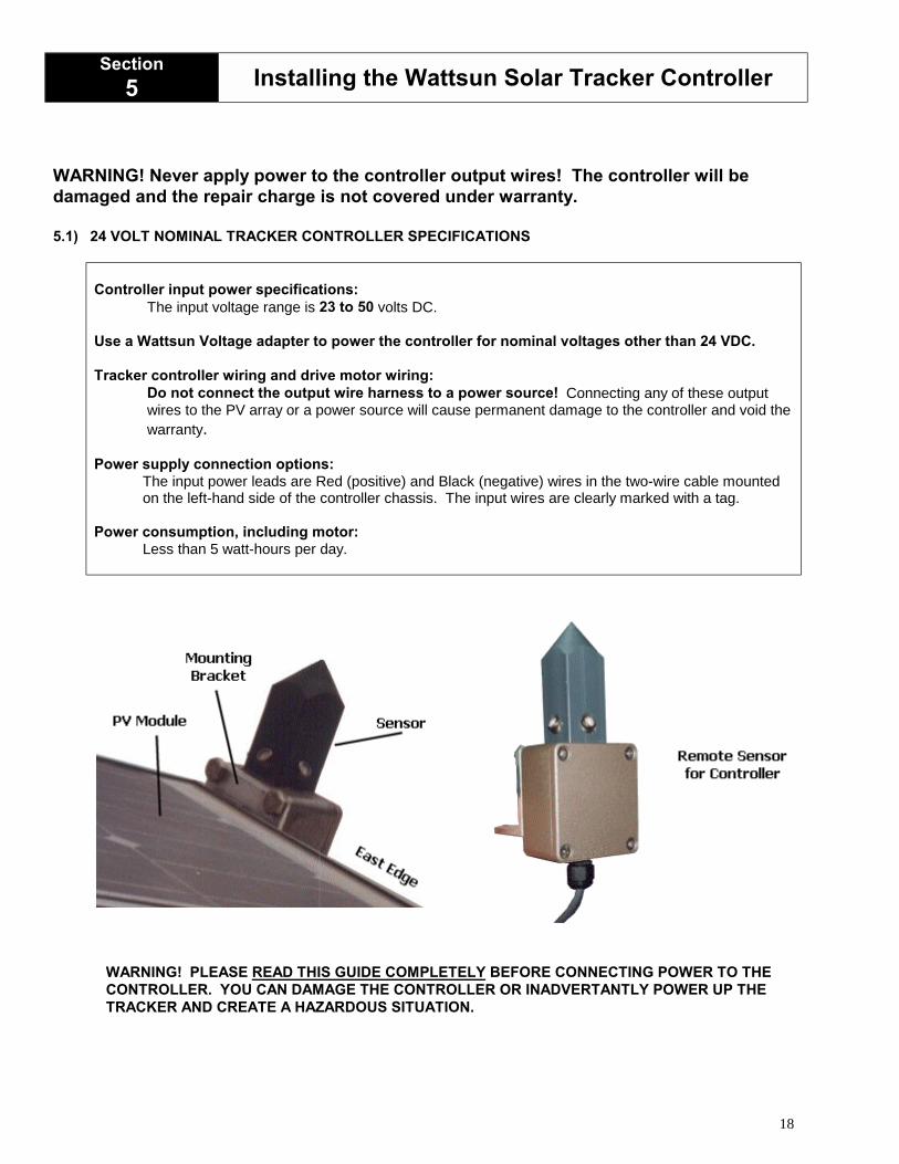
WARNING! Never apply power to the controller output wires! The controller will bedamaged and the repair charge is not covered under warranty.
5.1) 24 VOLT NOMINAL TRACKER CONTROLLER SPECIFICATIONS
Controller input power specifications:The input voltage range is 23 to 50 volts DC.
Use a Wattsun Voltage adapter to power the controller for nominal voltages other than 24 VDC.
Tracker controller wiring and drive motor wiring:Do not connect the output wire harness to a power source! Connecting any of these outputwires to the PV array or a power source will cause permanent damage to the controller and void thewarranty.
Power supply connection options:The input power leads are Red (positive) and Black (negative) wires in the two-wire cable mountedon the left-hand side of the controller chassis. The input wires are clearly marked with a tag.
Power consumption, including motor:Less than 5 watt-hours per day.
WARNING! PLEASE READ THIS GUIDE COMPLETELY BEFORE CONNECTING POWER TO THECONTROLLER. YOU CAN DAMAGE THE CONTROLLER OR INADVERTANTLY POWER UP THETRACKER AND CREATE A HAZARDOUS SITUATION.

19
WATTSUN TRACKER CONTROLLER: FUNCTION AND FEATURES.
WARNING! The last connection made is from a power source to the tracker controller! Please readSections 4, 5, 6, 7 and 8. Failure to do so might cause you harm or injury.
OVERVIEW
Wattsun™ Solar Trackers utilize a patented, closed loop, optical sensing system to sense the sun’s positionand track it. The sun sensors are mounted on the remote chassis and feed information to the controlelectronics about the direct component of sunlight available, the diffuse amount of sunlight, the total amountof sunlight as well as the differential amount of sunlight on opposing sensors. Based on this information, thecontroller seeks to equalize the sunlight received by opposing sensors for each axis.
The controller circuitry automatically adjusts the tracker sensitivity. It increases the sensitivity with increaseddirect sunlight and decreases the sensitivity with scattered or diffused light - present during cloudyconditions. This enables the tracker to eliminate undue hunting in cloudy or overcast conditions when thesunlight is scattered. It also adjusts according to the total amount of light received by the sensors.
Since the sensor knows how much light is available, it enables the controller to sense sunset, and return tothe sunrise position in the evening - if the controller is connected to a battery bank. When it is powereddirectly from the PV array, the tracker returns to sunrise at first morning light. The controller uses energyintegration circuitry, enabling the tracker to move with as little as 20ma of available current.
The tracker controller sends a signal to the DC gear motor that moves the PV array to a perpendicularposition relative to the sun’s rays. The motors are small, fraction HP, low voltage, gear motors that move thetracker into position. The gearing is designed such that high winds or other forces cannot drive the trackerback. Since they are DC drive motors, one polarity moves them in the forward direction and reversing thepolarity moves them in the opposite direction. When the controller wants the tracker to move, it sends asignal of the appropriate polarity to the DC gear-motor. Once the tracker has moved to the “on track”position, the controller electrically “brakes” the motor to stop movement that results in greater trackingaccuracy.
STANDARD FEATURES OF YOUR SINGLE-AXIS WATTSUN CONTROLLER
♦ Sensor mounts independently of the main chassis.♦ The controller only operates the East/West axis.♦ Dip switches to test the East and West Limits.♦ Controller outputs are short circuit protected and will limit the output current to 3 amps.♦ Inside controller chassis are light sensitivity adjustment potentiometers for Azimuth and Elevation.♦ Controller is equipped with a 5-amp automotive spade type fuse (ATO) inside the controller chassis.♦ Filtering to protect the tracker motor against "noisy" PWM charge controllers.♦ Improved lightning protection.
20
21
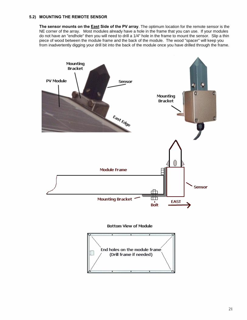
5.2) MOUNTING THE REMOTE SENSOR
The sensor mounts on the East Side of the PV array. The optimum location for the remote sensor is theNE corner of the array. Most modules already have a hole in the frame that you can use. If your modulesdo not have an "endhole" then you will need to drill a 1/4" hole in the frame to mount the sensor. Slip a thinpiece of wood between the module frame and the back of the module. The wood "spacer" will keep youfrom inadvertently digging your drill bit into the back of the module once you have drilled through the frame.
22
Section6 Power Connection to the East-West Actuator
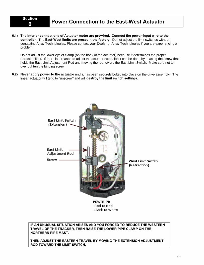
6.1) The interior connections of Actuator motor are prewired. Connect the power-input wire to thecontroller. The East-West limits are preset in the factory. Do not adjust the limit switches withoutcontacting Array Technologies. Please contact your Dealer or Array Technologies if you are experiencing aproblem.
Do not adjust the lower eyelet clamp (on the body of the actuator) because it determines the properretraction limit. If there is a reason to adjust the actuator extension it can be done by relaxing the screw thatholds the East Limit Adjustment Rod and moving the rod toward the East Limit Switch. Make sure not toover tighten the binding screw!
6.2) Never apply power to the actuator until it has been securely bolted into place on the drive assembly. Thelinear actuator will tend to "unscrew" and will destroy the limit switch settings.
IF AN UNUSUAL SITUATION ARISES AND YOU FORCED TO REDUCE THE WESTERNTRAVEL OF THE TRACKER, THEN RAISE THE LOWER PIPE CLAMP ON THENORTHERN PIPE MAST.
THEN ADJUST THE EASTERN TRAVEL BY MOVING THE EXTENSION ADJUSTMENTROD TOWARD THE LIMIT SWITCH.
23
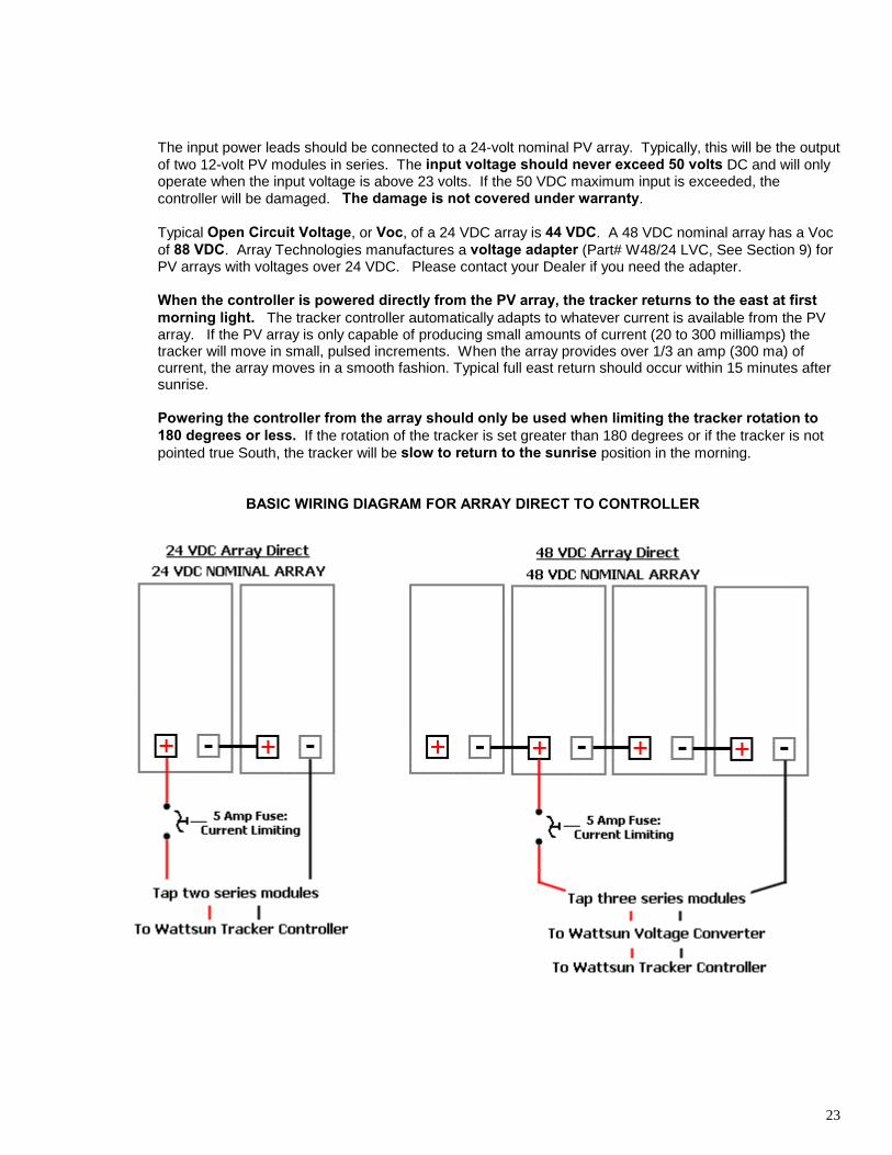
The input power leads should be connected to a 24-volt nominal PV array. Typically, this will be the outputof two 12-volt PV modules in series. The input voltage should never exceed 50 volts DC and will onlyoperate when the input voltage is above 23 volts. If the 50 VDC maximum input is exceeded, thecontroller will be damaged. The damage is not covered under warranty.
Typical Open Circuit Voltage, or Voc, of a 24 VDC array is 44 VDC. A 48 VDC nominal array has a Vocof 88 VDC. Array Technologies manufactures a voltage adapter (Part# W48/24 LVC, See Section 9) forPV arrays with voltages over 24 VDC. Please contact your Dealer if you need the adapter.
When the controller is powered directly from the PV array, the tracker returns to the east at firstmorning light. The tracker controller automatically adapts to whatever current is available from the PVarray. If the PV array is only capable of producing small amounts of current (20 to 300 milliamps) thetracker will move in small, pulsed increments. When the array provides over 1/3 an amp (300 ma) ofcurrent, the array moves in a smooth fashion. Typical full east return should occur within 15 minutes aftersunrise.
Powering the controller from the array should only be used when limiting the tracker rotation to180 degrees or less. If the rotation of the tracker is set greater than 180 degrees or if the tracker is notpointed true South, the tracker will be slow to return to the sunrise position in the morning.
BASIC WIRING DIAGRAM FOR ARRAY DIRECT TO CONTROLLER
24
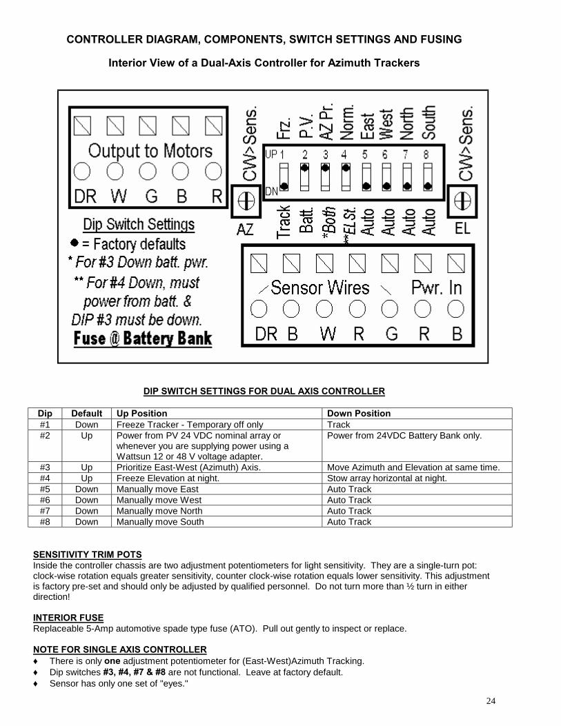
CONTROLLER DIAGRAM, COMPONENTS, SWITCH SETTINGS AND FUSING
Interior View of a Dual-Axis Controller for Azimuth Trackers
DIP SWITCH SETTINGS FOR DUAL AXIS CONTROLLER
Dip Default Up Position Down Position#1 Down Freeze Tracker - Temporary off only Track#2 Up Power from PV 24 VDC nominal array or
whenever you are supplying power using aWattsun 12 or 48 V voltage adapter.
Power from 24VDC Battery Bank only.
#3 Up Prioritize East-West (Azimuth) Axis. Move Azimuth and Elevation at same time.#4 Up Freeze Elevation at night. Stow array horizontal at night.#5 Down Manually move East Auto Track#6 Down Manually move West Auto Track#7 Down Manually move North Auto Track#8 Down Manually move South Auto Track
SENSITIVITY TRIM POTSInside the controller chassis are two adjustment potentiometers for light sensitivity. They are a single-turn pot:clock-wise rotation equals greater sensitivity, counter clock-wise rotation equals lower sensitivity. This adjustmentis factory pre-set and should only be adjusted by qualified personnel. Do not turn more than ½ turn in eitherdirection!
INTERIOR FUSEReplaceable 5-Amp automotive spade type fuse (ATO). Pull out gently to inspect or replace.
NOTE FOR SINGLE AXIS CONTROLLER♦ There is only one adjustment potentiometer for (East-West)Azimuth Tracking.♦ Dip switches #3, #4, #7 & #8 are not functional. Leave at factory default.♦ Sensor has only one set of "eyes."
25
Section7
Setting Preferences and Operatingthe Tracker Controller
OPERATING THE CONTROLLER
7.1) Visually inspect the area around the array. Make sure that there in nothing in the way of the trackerwhen it begins to rotate. A common mistake is to leave a ladder standing nearby.
7.2) Inspect the wiring from the array to the controller and your junction box. Make sure that all wire serviceloops are long enough and that the wires are free from binding at all pivot points. Is there enough slack inthe wires to accommodate 180 degrees of azimuth rotation in either direction?
7.3) Pull your exterior fuse or disconnect switch, to break the power to the controller.
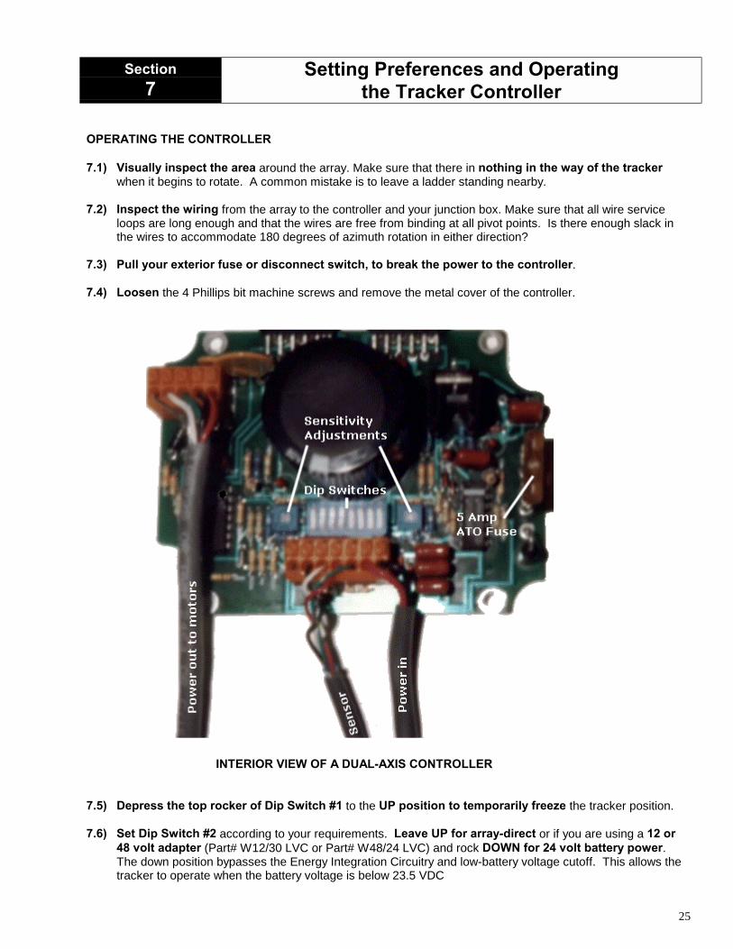
7.4) Loosen the 4 Phillips bit machine screws and remove the metal cover of the controller.
INTERIOR VIEW OF A DUAL-AXIS CONTROLLER
7.5) Depress the top rocker of Dip Switch #1 to the UP position to temporarily freeze the tracker position.
7.6) Set Dip Switch #2 according to your requirements. Leave UP for array-direct or if you are using a 12 or48 volt adapter (Part# W12/30 LVC or Part# W48/24 LVC) and rock DOWN for 24 volt battery power.The down position bypasses the Energy Integration Circuitry and low-battery voltage cutoff. This allows thetracker to operate when the battery voltage is below 23.5 VDC
26
7.7) DUAL AXIS OPTION ONLY: If you power the controller directly from a 24 volt battery bank, you mayset Dip Switch #3, to the down position if you want the to track both azimuth and elevation at the same time.Leave in the default position if your system voltage is not 24VDC.
7.8) DUAL AXIS OPTION ONLY: Leave Dip Switch #4 set to the UP Position unless you want to stow thearray horizontal at night. Available only when you are powered from a battery bank. One reason to do so isif you receive strong winds during the evening. Do not stow the array horizontal at night if you are in an areathat receives heavy snowfall. Horizontal stow is available in two ways: (1) If Dip Switch #3 is set to theDOWN position and you are powering the controller from a 24 VDC battery bank. (2) If Dip Switch #2 isset to the UP position and you use a 12 or 48 volt adapter (Part# W12/30 LVC or Part# W48/24 LVC) thatis powered from a battery bank.
7.9) Inspect the area around the tracker again. Remove any ladders, tools or obstructions from the area.
7.10) Replace the battery fuse and or disconnect.
7.11) Depress the bottom rocker of Dip Switch #1 to Track.
7.12) After a 3 second delay, the tracker will move and track the sun.
7.13) Manually move the tracker East by depressing the top of Dip Switch # 5.Depress the bottom of Dip Switch # 5 to return to Auto Tracking.
7.14) Manually move the tracker West by depressing the top of Dip Switch # 6.Depress the bottom of Dip Switch # 6 to return to Auto Tracking.
7.15) Setting the Sensor Light Sensitivity: The sensor sensitivity is preset at the factory. Inside the controllerchassis are two adjustment potentiometers for light sensitivity. They are a single-turn pot: clockwise rotationequals greater sensitivity, counter-clockwise rotation equals lower sensitivity. Only qualified personnelshould perform this adjustment. Do not turn more than ½ turn in either direction!
27
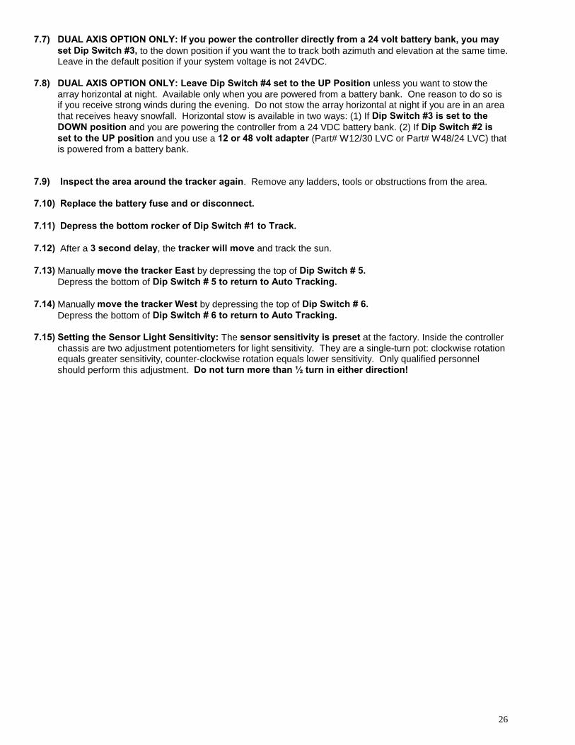
Section8 Setting the Actuator Motor Limits
THE LIMITS FOR YOUR TRACKER ARE PRESET AT THE FACTORY. PLEASE CONTACT ARRAYTECHNOLOGIES IF YOU WANT TO CHANGE THE SETTINGS.
IF AN UNUSUAL SITUATION ARISES AND YOU FORCED TO REDUCE THE WESTERN TRAVEL OFTHE TRACKER, THEN RAISE THE LOWER PIPE CLAMP ON THE NORTHERN PIPE MAST.
THEN ADJUST THE EASTERN TRAVEL BY MOVING THE EXTENSION ADJUSTMENT ROD TOWARDTHE LIMIT SWITCH.
ALWAYS RUN THE TRACKER THROUGH THE ENTIRE RANGE OF MOTION AFTER ADJUSTIMG THELIMITS!
28
Section9 Wattsun 48V Linear Voltage Pre-regulator
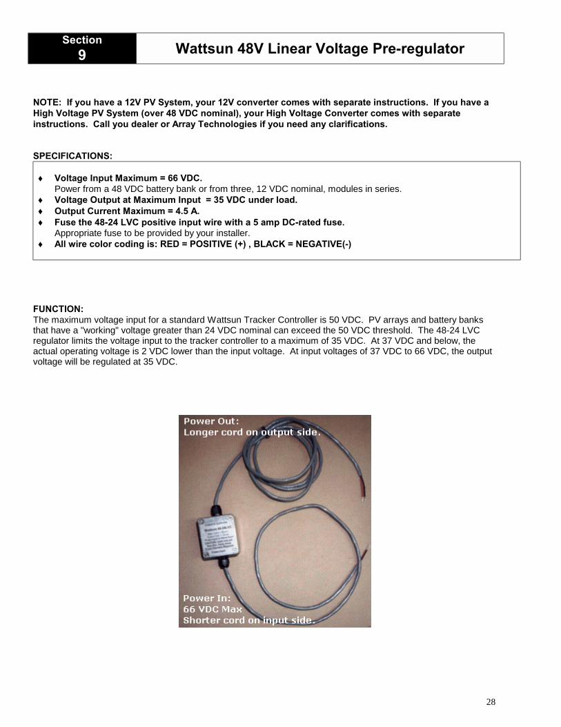
NOTE: If you have a 12V PV System, your 12V converter comes with separate instructions. If you have aHigh Voltage PV System (over 48 VDC nominal), your High Voltage Converter comes with separateinstructions. Call you dealer or Array Technologies if you need any clarifications.
SPECIFICATIONS:
♦ Voltage Input Maximum = 66 VDC.Power from a 48 VDC battery bank or from three, 12 VDC nominal, modules in series.
♦ Voltage Output at Maximum Input = 35 VDC under load.♦ Output Current Maximum = 4.5 A.♦ Fuse the 48-24 LVC positive input wire with a 5 amp DC-rated fuse.
Appropriate fuse to be provided by your installer.♦ All wire color coding is: RED = POSITIVE (+) , BLACK = NEGATIVE(-)
FUNCTION:The maximum voltage input for a standard Wattsun Tracker Controller is 50 VDC. PV arrays and battery banksthat have a "working" voltage greater than 24 VDC nominal can exceed the 50 VDC threshold. The 48-24 LVCregulator limits the voltage input to the tracker controller to a maximum of 35 VDC. At 37 VDC and below, theactual operating voltage is 2 VDC lower than the input voltage. At input voltages of 37 VDC to 66 VDC, the outputvoltage will be regulated at 35 VDC.
29
INSTALLING THE 48-24 LVC:1) Disconnect the main battery bank or PV array circuit so that no power can flow through any wires you are
working on.
2) Connect the output of the voltage regulator (longer cable exiting the regulator) to the input power wires of theWattsun Tracker Controller. IE: Red to Red (+), Black to Black (-).
3) Fuse the input of the voltage regulator (shorter cable side) with a 5 amp DC rated fuse. The fuse is inserted inthe positive (Red,+) lead of the input wire.
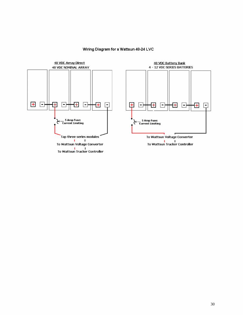
4. A) Battery bank connection: Connect the fused input side (two-wire, shorter cable) of the voltage regulatordirectly to the output of a 48-volt battery bank. Battery positive to fused red input. Battery negative to voltageregulator input negative.
4. B) PV array direct connection: Connect the fused input side (two-wire, shorter cable) of the voltage regulatordirectly to the output of three, 12- volt modules in series. When connecting directly to the PV Array: You willwant to make the connection on the lower side of the 4-module string. IE: From the negative of array to thepositive tap of the third module, in the 4-module, 48 VDC nominal string.
5) Open the Wattsun Solar Tracker Controller and set switch #2 to the UP (PV) Energy Integration setting.
6) Reconnect the main battery bank or PV array circuit so that power can flow through the voltage regulator andWattsun Solar Tracker Controller.
WARNING!♦ Connection to the output of 4-modules in series will exceed the 66 VDC maximum input of the voltage
regulator. The 48-24 LVC will be damaged and cause the Wattsun Solar Tracker Controller to fail.Warranty does not cover this damage. Both parts will have to be returned to the factory for repair!
♦ Never apply power into the 48-24 LVC output wires. Warranty does not cover this damage. Damagecan occur and it will have to be returned to the factory for repair!
♦ A self-resetting fuse is incorporated in the 48-24 LVC. If the output wires touch each other and areshorted, the interior fuse can blow and will disconnect the power output of the regulator. If thishappens: Repair the output short then reset the fuse. Disconnecting power to the regulator resets thefuse. Wait a minute for the fuse to cool. Then reconnect power to the regulator.
CAUTION!CONVERTOR CASE MAY GET VERY HOT UNDER HIGH LOAD OR SHORT CIRCUIT. DO NOT MOUNT TOA FLAMABLE SURFACE SUCH AS WOOD OR OTHER. DO NOT LET CHASSIS COME INTO CONTACTWITH OTHER WIRES AS HEAT MAY MELT INSULATION.
30
31
Section10 Manual Control Option
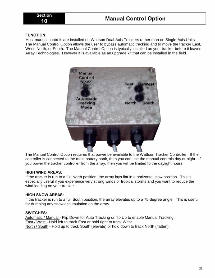
FUNCTION:Most manual controls are installed on Wattsun Dual-Axis Trackers rather than on Single-Axis Units.The Manual Control Option allows the user to bypass automatic tracking and to move the tracker East,West, North, or South. The Manual Control Option is typically installed on your tracker before it leavesArray Technologies. However it is available as an upgrade kit that can be installed in the field.
The Manual Control Option requires that power be available to the Wattsun Tracker Controller. If thecontroller is connected to the main battery bank, then you can use the manual controls day or night. Ifyou power the tracker controller from the array, then you will be limited to the daylight hours.
HIGH WIND AREAS:If the tracker is run to a full North position, the array lays flat in a horizontal stow position. This isespecially useful if you experience very strong winds or tropical storms and you want to reduce thewind loading on your tracker.
HIGH SNOW AREAS:If the tracker is run to a full South position, the array elevates up to a 75-degree angle. This is usefulfor dumping any snow accumulation on the array.
SWITCHES:Automatic / Manual - Flip Down for Auto Tracking or flip Up to enable Manual Tracking.East / West - Hold left to track East or hold right to track West.North / South - Hold up to track South (elevate) or hold down to track North (flatten).

32
Section11 Periodic Maintenance
PERIODIC MAINTENANCE
♦ Maintenance should be performed at least once a year. More often if your tracker is installed in severeweather areas.
♦ Inspect all the tracker hardware and the modules bolts for tightness and tighten all nuts and bolts thatneed it.
♦ Inspect all wires for abrasion and gently tug on them to make sure that they are secure.
♦ The grease zerk on each pillow block should receive 4-6 pumps of lithium-base general-purpose chassisgrease from a grease gun.
♦ Spray the inner tube (telescoping part) of the linear actuator with a lubricating rust inhibitor. (We use LPS-3)
33
Section12 Suggested Methods for Grounding a Tracker
WARNING!
• The information provided here is a general guideline for grounding yourWattsun Solar Tracker.
• This information is not a substitute for following the National ElectricalCode.
• You should hire a qualified Electrician, Electrical Contractor or SolarProfessional to install and wire your Wattsun Solar Tracker.
• Array Technologies does not assume any liability for your failure to adhereto the NEC.
• Failure to ground your tracker may void your Wattsun Warranty and mayresult in damage to your Wattsun Solar Tracker Controller or motors.
REFERENCES:
Grounding the South FortyJohn WilesCode CornerHome Power MagazineIssue # 74December 1999 / January 2000http://www.sandia.gov/pv/pvsys/sforty.pdf
To Ground or Not to GroundJohn WilesCode CornerHome Power MagazineIssue # 72August 1999 / September 1999http://www.sandia.gov/pv/pvsys/groundcdcrnr.pdf
Codes, Standards, and Safety available online at: http://www.sandia.gov/pv/sfty.htm
34
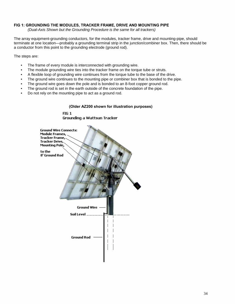
FIG 1: GROUNDING THE MODULES, TRACKER FRAME, DRIVE AND MOUNTING PIPE(Dual-Axis Shown but the Grounding Procedure is the same for all trackers)
The array equipment-grounding conductors, for the modules, tracker frame, drive and mounting-pipe, shouldterminate at one location—probably a grounding terminal strip in the junction/combiner box. Then, there should bea conductor from this point to the grounding electrode (ground rod).
The steps are:
• The frame of every module is interconnected with grounding wire.• The module grounding wire ties into the tracker frame on the torque tube or struts.• A flexible loop of grounding wire continues from the torque tube to the base of the drive.• The ground wire continues to the mounting pipe or combiner box that is bonded to the pipe.• The ground wire goes down the pole and is bonded to an 8-foot copper ground rod.• The ground rod is set in the earth outside of the concrete foundation of the pipe.• Do not rely on the mounting pipe to act as a ground rod.
(Older AZ200 shown for illustration purposes)
35
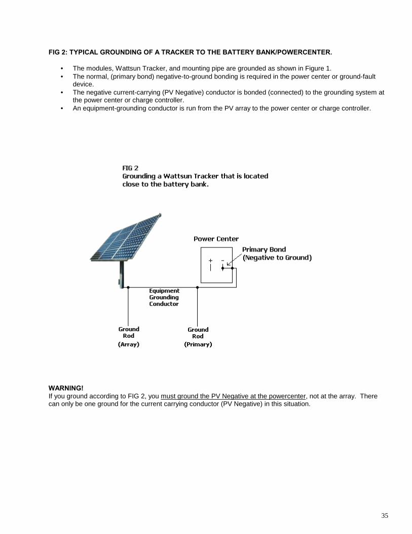
FIG 2: TYPICAL GROUNDING OF A TRACKER TO THE BATTERY BANK/POWERCENTER.
• The modules, Wattsun Tracker, and mounting pipe are grounded as shown in Figure 1.• The normal, (primary bond) negative-to-ground bonding is required in the power center or ground-fault
device.• The negative current-carrying (PV Negative) conductor is bonded (connected) to the grounding system at
the power center or charge controller.• An equipment-grounding conductor is run from the PV array to the power center or charge controller.
WARNING!If you ground according to FIG 2, you must ground the PV Negative at the powercenter, not at the array. Therecan only be one ground for the current carrying conductor (PV Negative) in this situation.
36
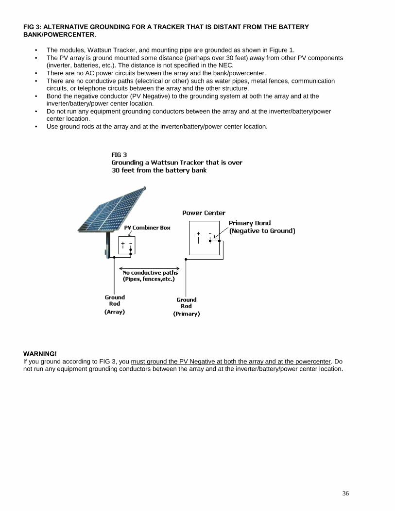
FIG 3: ALTERNATIVE GROUNDING FOR A TRACKER THAT IS DISTANT FROM THE BATTERYBANK/POWERCENTER.
• The modules, Wattsun Tracker, and mounting pipe are grounded as shown in Figure 1.• The PV array is ground mounted some distance (perhaps over 30 feet) away from other PV components
(inverter, batteries, etc.). The distance is not specified in the NEC.• There are no AC power circuits between the array and the bank/powercenter.• There are no conductive paths (electrical or other) such as water pipes, metal fences, communication
circuits, or telephone circuits between the array and the other structure.• Bond the negative conductor (PV Negative) to the grounding system at both the array and at the
inverter/battery/power center location.• Do not run any equipment grounding conductors between the array and at the inverter/battery/power
center location.• Use ground rods at the array and at the inverter/battery/power center location.
WARNING!If you ground according to FIG 3, you must ground the PV Negative at both the array and at the powercenter. Donot run any equipment grounding conductors between the array and at the inverter/battery/power center location.
37
Section13 Array Technologies, Inc. Limited Warranty
Array Technologies, Inc. warrants its Wattsun™ Solar Trackers to the original consumer purchaser that it willrepair, or replace, at Array Technologies Inc.’s option, any Wattsun™ Tracker component that is determined to bedefective in material or workmanship for the following terms:
Two years from date of purchase on all components including tracker controller, frame, azimuth driveassembly, and actuator.
To be eligible for repair or replacement under this warranty, the part in question must be sent to ArrayTechnologies, Inc. within the warranty period and the original consumer purchaser must comply with the followingconditions:
♦ The tracker or component thereof must not have been modified or altered in any way by an unauthorizedsource.
♦ The tracker or component thereof must have been installed in accordance with the installation instructionsincluding electrical connections of tracking controller.
This limited warranty does not cover:♦ Damage due to improper or installation;♦ Accidental or intentional damage;♦ Misuse, abuse, corrosion, or neglect;♦ Products impaired by severe conditions, such as excessive wind, ice, storms or other natural occurrences;♦ Trackers used for purposes other than the intended use, including mounting modules or components which
the tracker was not intended for;♦ Trackers with more than the intended number and type of modules mounted on it;♦ Damage due to improper packaging on return shipment.
Any and all labor charges for troubleshooting, removal or replacement of tracker and/or components ofthe tracker are not covered by this warranty and will not be honored by Array Technologies, Inc.
Return shipping is to be pre-paid by the original consumer purchaser. Array Technologies, Inc. will pay the normalreturn UPS shipping charges within the USA only.
THIS WARRANTY IS EXPRESSLY IN LIEU OF ALL OTHER WARRANTIES OF ANY KIND, EXPRESSED ORIMPLIED, INCLUDING (WITHOUT LIMITATION) ANY IMPLIED WARRANTIES OF MERCHANTABILITY ORFITNESS FOR A PARTICULAR PURPOSE, AND OF ANY NONCONTRACTUAL LIABILITIES BASED UPONNEGLIGENCE OR STRICT LIABILITY. IN NO EVENT SHALL ARRAY TECHNOLOGIES, INC. BE LIABLE FORINCIDENTAL OR CONSEQUENTIAL DAMAGES, INCLUDING (WITHOUT LIMITATIONS) ANY DAMAGE FORPERSONAL INJURY OR PROPERTY DAMAGE OR OTHER PRODUCT LIABILITIES BASED UPON ALLEGEDNEGLIGENCE OR BREACH OF EXPRESS OR IMPLIED WARRANTIES OR STRICT LIABILITY. ARRAYTECHNOLOGIES, INC. NEITHER ASSUMES NOR AUTHORIZES ANY OTHER PERSON TO ASSUME FOR ITANY OTHER OBLIGATION IN CONNECTION WITH THE SALE OF ITS WATTSUN™ SOLAR TRACKERS.
THIS WARRANTY GIVES YOU SPECIFIC LEGAL RIGHTS, AND YOU ALSO MAY HAVE OTHER RIGHTSTHAT MAY VARY FROM STATE TO STATE. SOME STATES DO NOT ALLOW LIMITATIONS ON HOW LONGAN IMPLIED WARRANTY WILL LAST OR THE EXCLUSION OR LIMITATION OF INCIDENTAL ORCONSEQUENTIAL DAMAGES, SO THE ABOVE LIMITATIONS OR EXCLUSIONS MAY NOT APPLY TO YOU.
Array Technologies, Inc.3312 Stanford NEAlbuquerque, NM 87107
Tel: 505-881-7567Fax: 505-881-7572
URL: www.wattsun.com