Embed Size (px)
Citation preview
Hands On: Cutting and Connectorizing UTP
Chapter 3a
Panko’s Business Data Networks and Telecommunications, 6th edition
Copyright 2007 Prentice-Hall May only be used by adopters of the book
3a-2
Recap: 4-Pair Unshielded Twisted Pair Cable with RJ-45 Connector
Single Twisted Pair
Jacket
Four pairs (each pair is twisted) are enclosed in a jacket.
3a-3
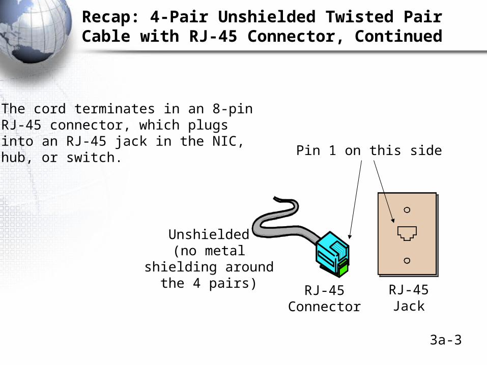
Recap: 4-Pair Unshielded Twisted Pair Cable with RJ-45 Connector, Continued
The cord terminates in an 8-pinRJ-45 connector, which plugsinto an RJ-45 jack in the NIC,hub, or switch. Pin 1 on this side
RJ-45Jack
RJ-45Connector
Unshielded(no metal
shielding aroundthe 4 pairs)
3a-4
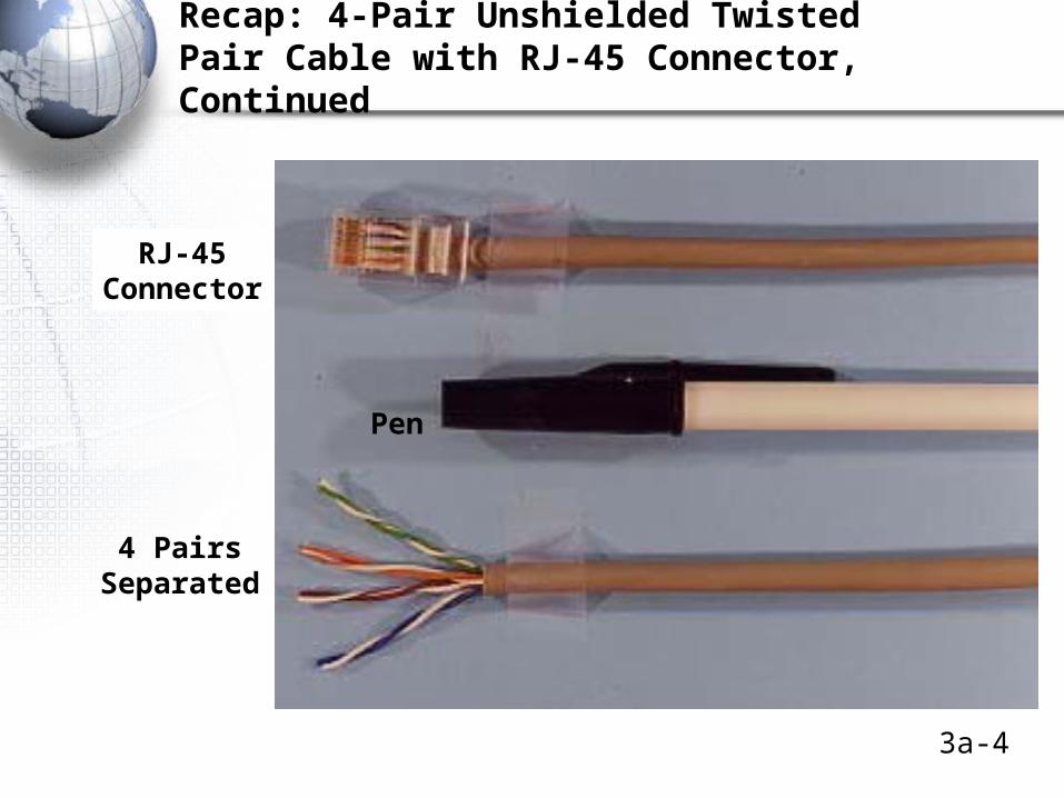
Recap: 4-Pair Unshielded TwistedPair Cable with RJ-45 Connector, Continued
RJ-45Connector
4 PairsSeparated
Pen
3a-5
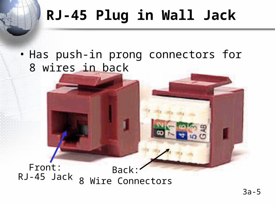
RJ-45 Plug in Wall Jack
• Has push-in prong connectors for 8 wires in back
Front:RJ-45 Jack
Back:8 Wire Connectors

3a-6
Solid-Wire Versus Stranded-Wire UTP
• Solid-Wire UTP
– Each of the eight wires is a solid wire surrounded by insulation
– Solid wires have low attenuation and so can reach 100 meters
– Easy to connectorize (add connectors to)
– Brittle and easy to break if handled roughly. Not good for runs through open office areas
3a-7
Solid-Wire Versus Stranded-Wire UTP, Continued
• Stranded-Wire UTP
– Each of the eight “wires” is really several thin strands of wire surrounded by insulation
– Flexible and rugged: ideal for running around an office area
– Higher attenuation than solid-wire UTP so can only be used in short runs—up to about 10 meters
3a-8
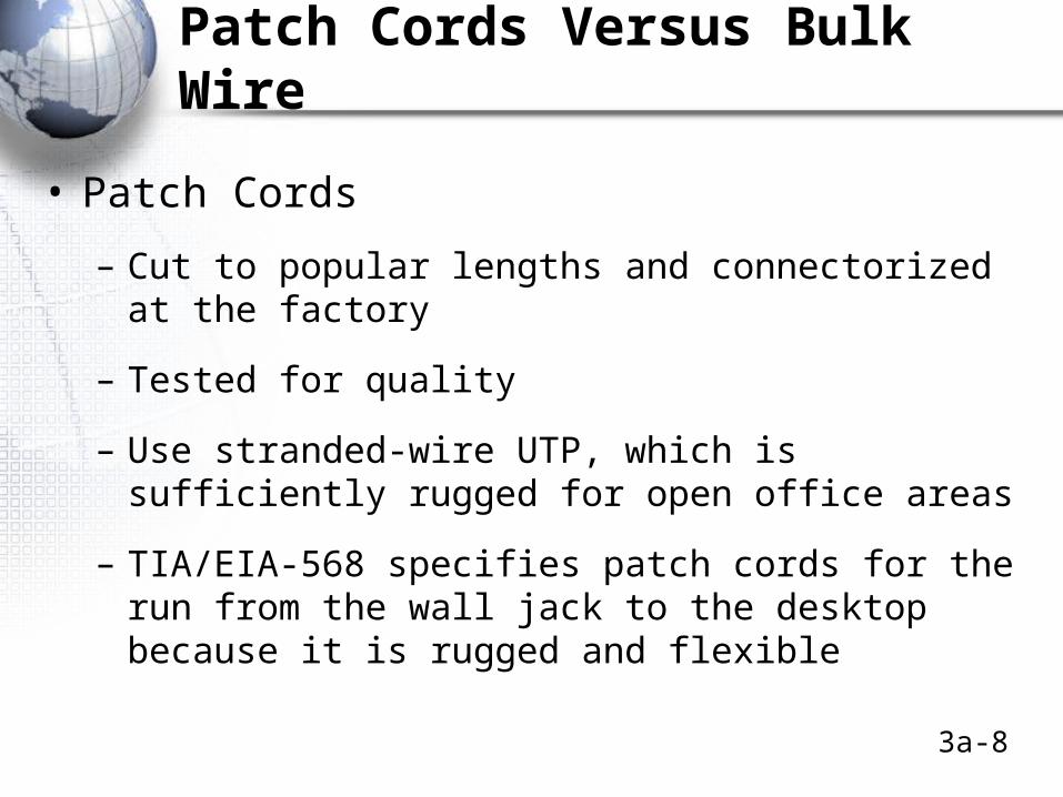
Patch Cords Versus Bulk Wire
• Patch Cords
– Cut to popular lengths and connectorized at the factory
– Tested for quality
– Use stranded-wire UTP, which is sufficiently rugged for open office areas
– TIA/EIA-568 specifies patch cords for the run from the wall jack to the desktop because it is rugged and flexible
3a-9
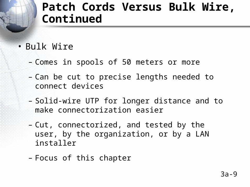
Patch Cords Versus Bulk Wire, Continued
• Bulk Wire
– Comes in spools of 50 meters or more
– Can be cut to precise lengths needed to connect devices
– Solid-wire UTP for longer distance and to make connectorization easier
– Cut, connectorized, and tested by the user, by the organization, or by a LAN installer
– Focus of this chapter
3a-10
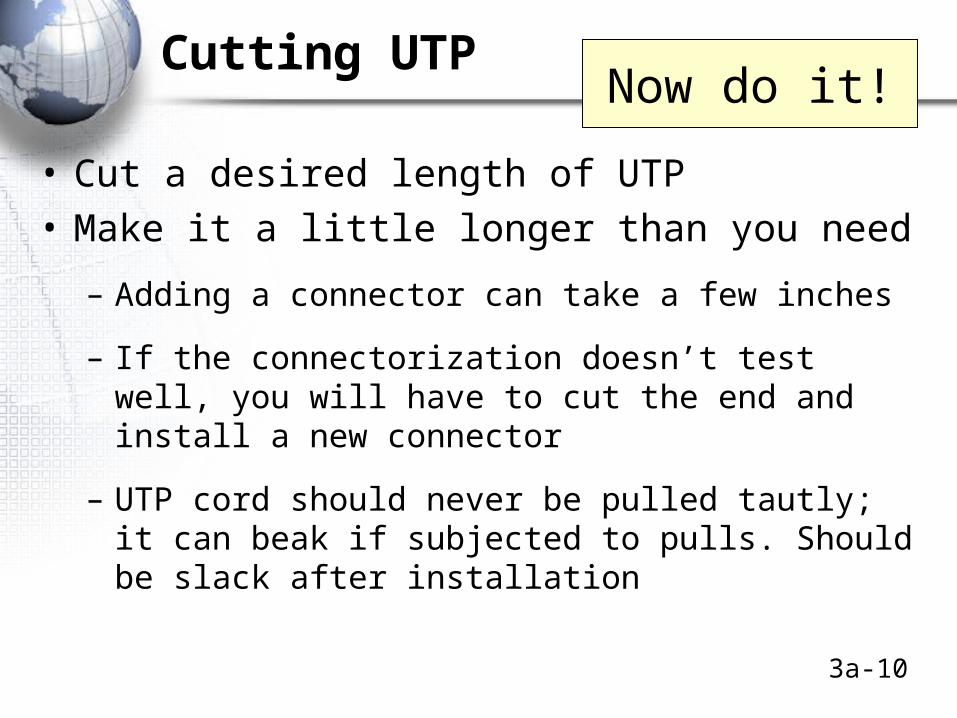
Cutting UTP
• Cut a desired length of UTP
• Make it a little longer than you need
– Adding a connector can take a few inches
– If the connectorization doesn’t test well, you will have to cut the end and install a new connector
– UTP cord should never be pulled tautly; it can beak if subjected to pulls. Should be slack after installation
Now do it!
3a-11
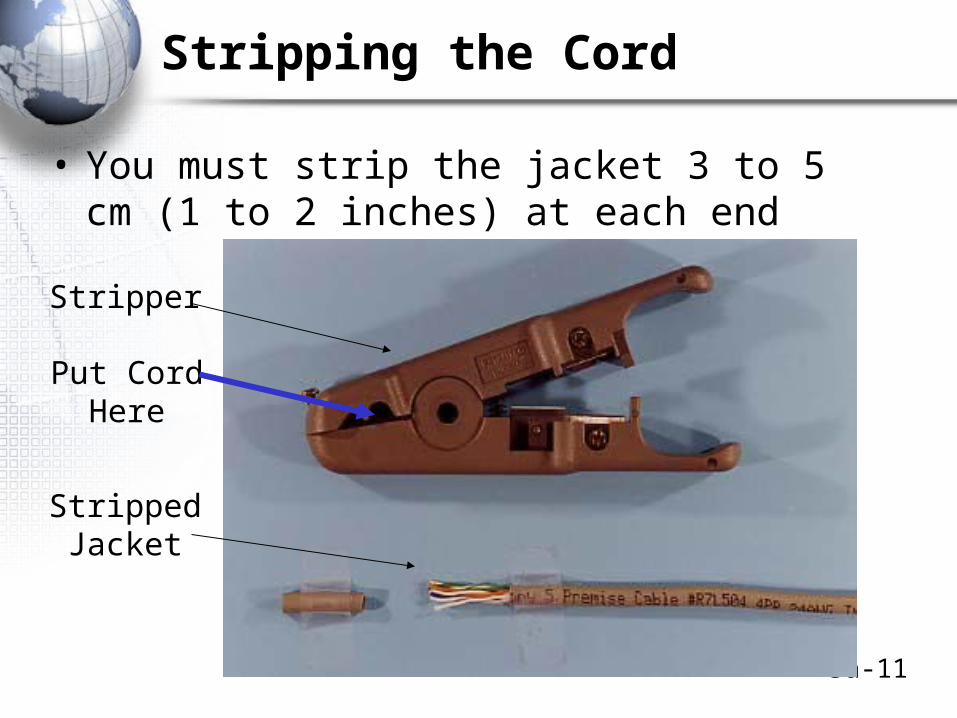
Stripping the Cord
• You must strip the jacket 3 to 5 cm (1 to 2 inches) at each end
StrippedJacket
Stripper
Put CordHere
3a-12
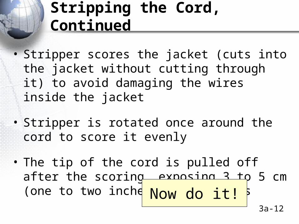
Stripping the Cord, Continued
• Stripper scores the jacket (cuts into the jacket without cutting through it) to avoid damaging the wires inside the jacket
• Stripper is rotated once around the cord to score it evenly
• The tip of the cord is pulled off after the scoring, exposing 3 to 5 cm (one to two inches) of the wires
Now do it!
3a-13
Putting Wires in Order
• There are orange, green, blue, and brown pairs
• Each pair has one wire with solid-color insulation and one wire that is white with bands of the pair’s color
• These wires will be placed in a particular order in the RJ-45 connector
3a-14
Putting Wires in Order, Continued
• There are two popular color schemes in TIA/EIA-568– T568A and T568B– T568B is the most commonly used color scheme
in the United States we will use it
• Note that T568A is a part of the TIA/EIA-568 standard, as is T568B
3a-15
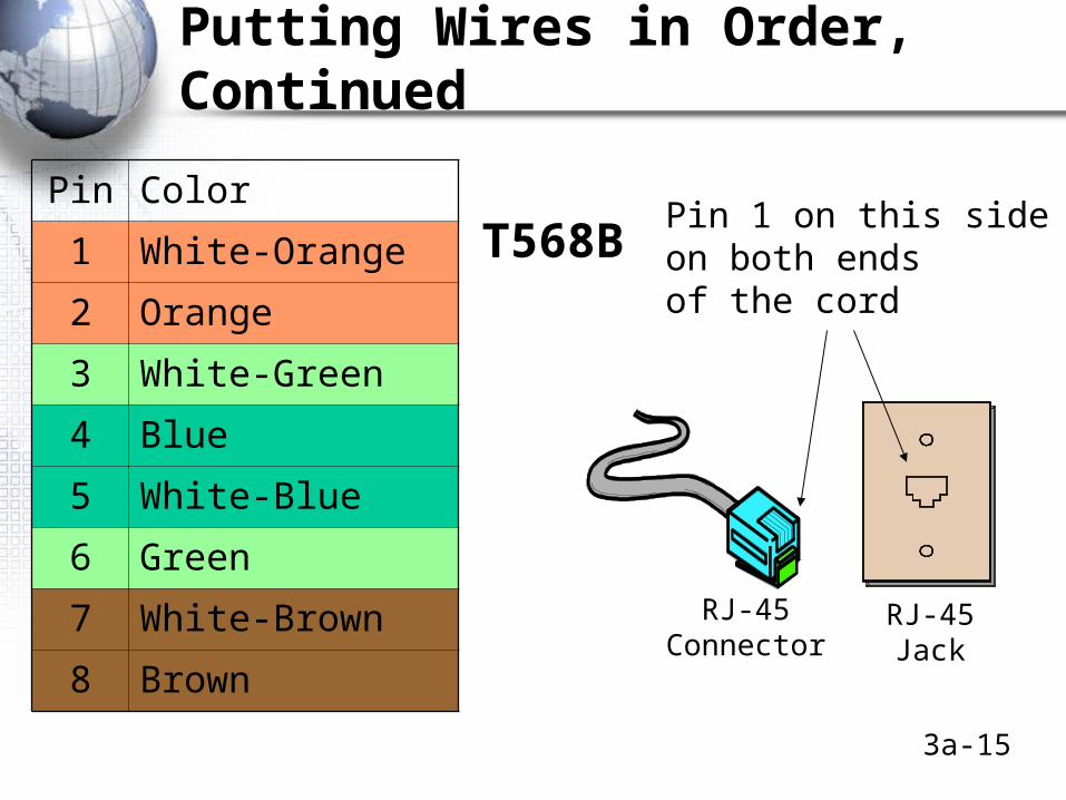
Putting Wires in Order, Continued
Pin 1 on this sideon both endsof the cord
RJ-45Jack
RJ-45Connector
T568BPin Color
1 White-Orange
2 Orange
3 White-Green
4 Blue
5 White-Blue
6 Green
7 White-Brown
8 Brown

3a-16
Putting Wires in Order, Continued
Pin Color
1 White-Orange
2 Orange
3 White-Green
4 Blue
5 White-Blue
6 Green
7 White-Brown
8 BrownT568B
NIC Transmits on 1 and 2 (Orange)
NIC Receives on 3 and 6 (Green)
3a-17
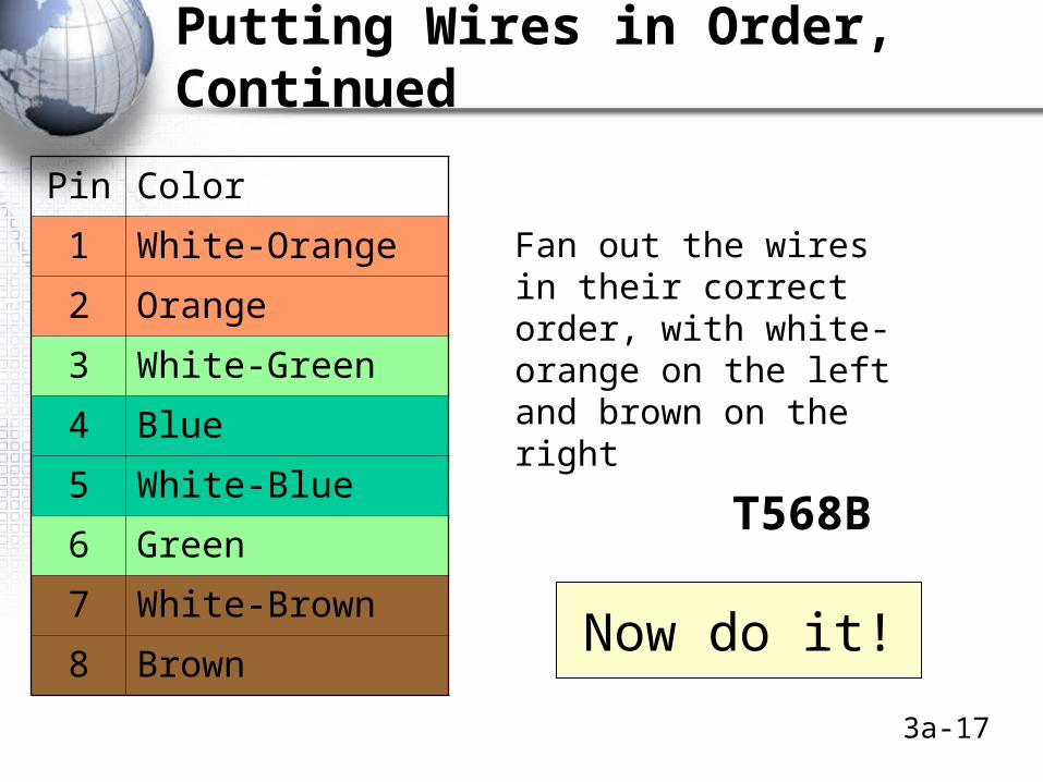
Putting Wires in Order, Continued
Pin Color
1 White-Orange
2 Orange
3 White-Green
4 Blue
5 White-Blue
6 Green
7 White-Brown
8 Brown
T568B
Fan out the wires in their correct order, with white-orange on the left and brown on the right
Now do it!
3a-18
Connectorize the Cord
• Cut the wires straight across so that no more than 1.25 cm (a half inch) of wires are exposed from the jacket
– This controls terminal cross-talk interference
• Be sure to cut straight across or the wires will not all reach the pins when you push them into the connector in the next step!
3a-19
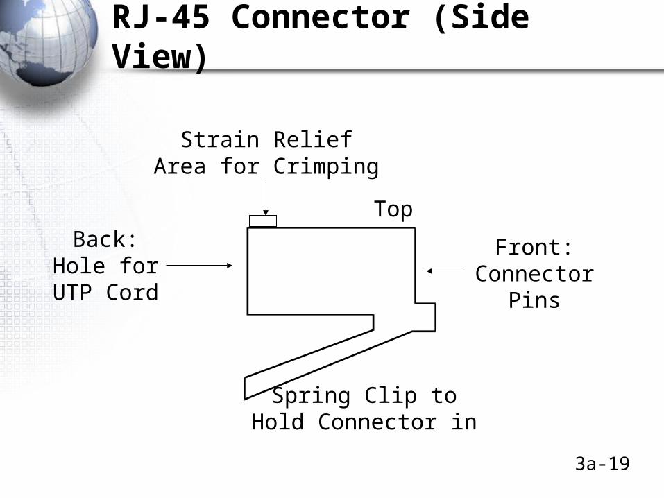
RJ-45 Connector (Side View)
Back:Hole for
UTP Cord
Spring Clip toHold Connector in
Front:Connector
Pins
Strain ReliefArea for Crimping
Top
3a-20
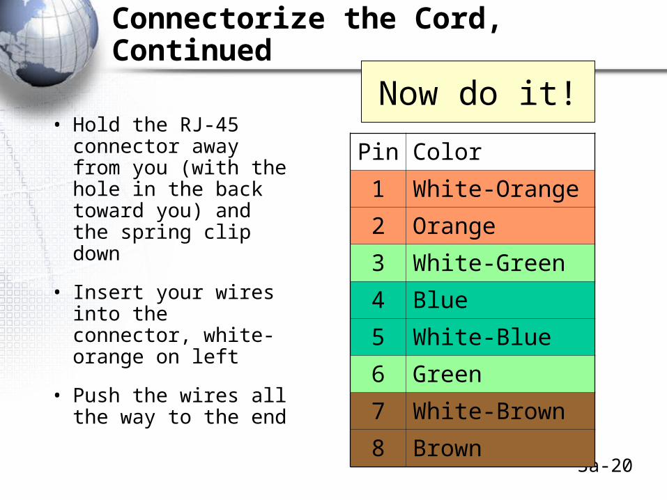
Connectorize the Cord, Continued
• Hold the RJ-45 connector away from you (with the hole in the back toward you) and the spring clip down
• Insert your wires into the connector, white-orange on left
• Push the wires all the way to the end
Now do it!
Pin Color
1 White-Orange
2 Orange
3 White-Green
4 Blue
5 White-Blue
6 Green
7 White-Brown
8 Brown
3a-21
Connectorize the Cord, Continued
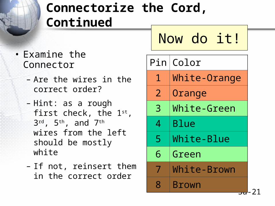
• Examine the Connector
– Are the wires in the correct order?
– Hint: as a rough first check, the 1st, 3rd, 5th, and 7th wires from the left should be mostly white
– If not, reinsert them in the correct order
Now do it!
Pin Color
1 White-Orange
2 Orange
3 White-Green
4 Blue
5 White-Blue
6 Green
7 White-Brown
8 Brown
3a-22
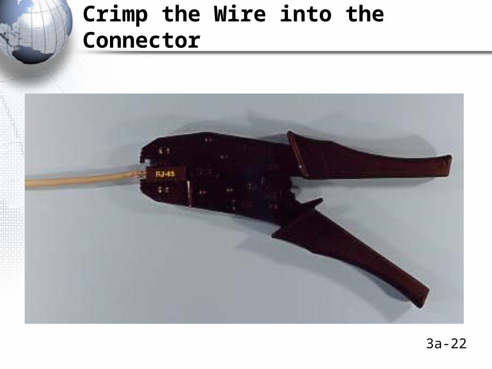
Crimp the Wire into the Connector
3a-23
Crimp the Wire Into the Connector, Continued
• Get a good crimper
• Cheap ones often fail to make a good connection
• Should have a ratchet for tightening without breaking the connector
3a-24
Crimp the Wire Into the Connector, Continued
• Press down to make a good connection. If you press too lightly, the connection will not work
• Crimping forces the pins on the front of the RJ-45 connector though the insulation, into each wire– Insulation displacement connection (IDC)
• This also crimps the cord at the back end of the connector for strain relief to keep the cord from pulling out if the cord is pulled
Now do it!
3a-25
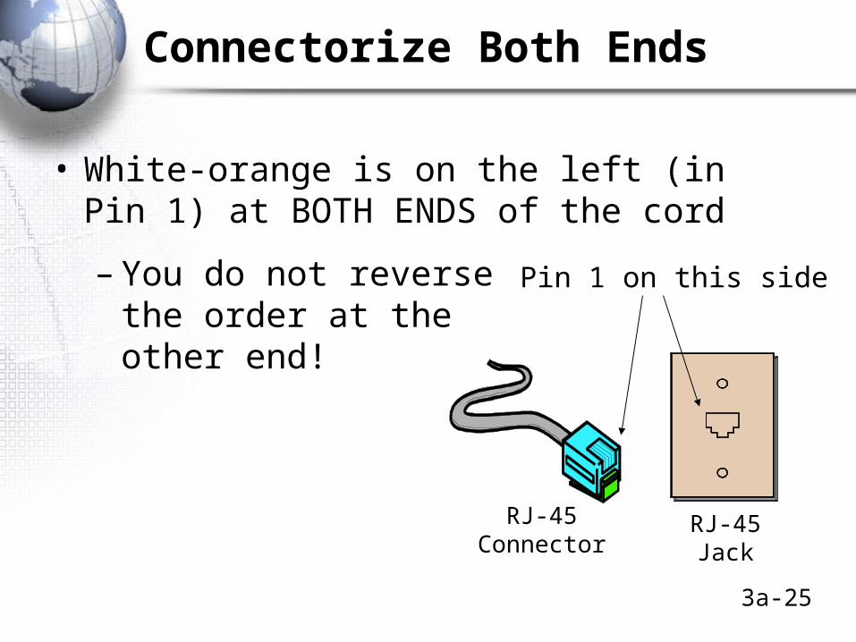
Connectorize Both Ends
• White-orange is on the left (in Pin 1) at BOTH ENDS of the cord
– You do not reverse the order at the other end!
Pin 1 on this side
RJ-45Jack
RJ-45Connector
3a-26
Test Your Cord
• After you have connectorized both ends, test your cord
• Misconnection is very common, so every cord must be checked
• Inexpensive continuity testers make sure wires are connected electrically and in the right order
• Expensive performance testers test for the quality of propagation
3a-27
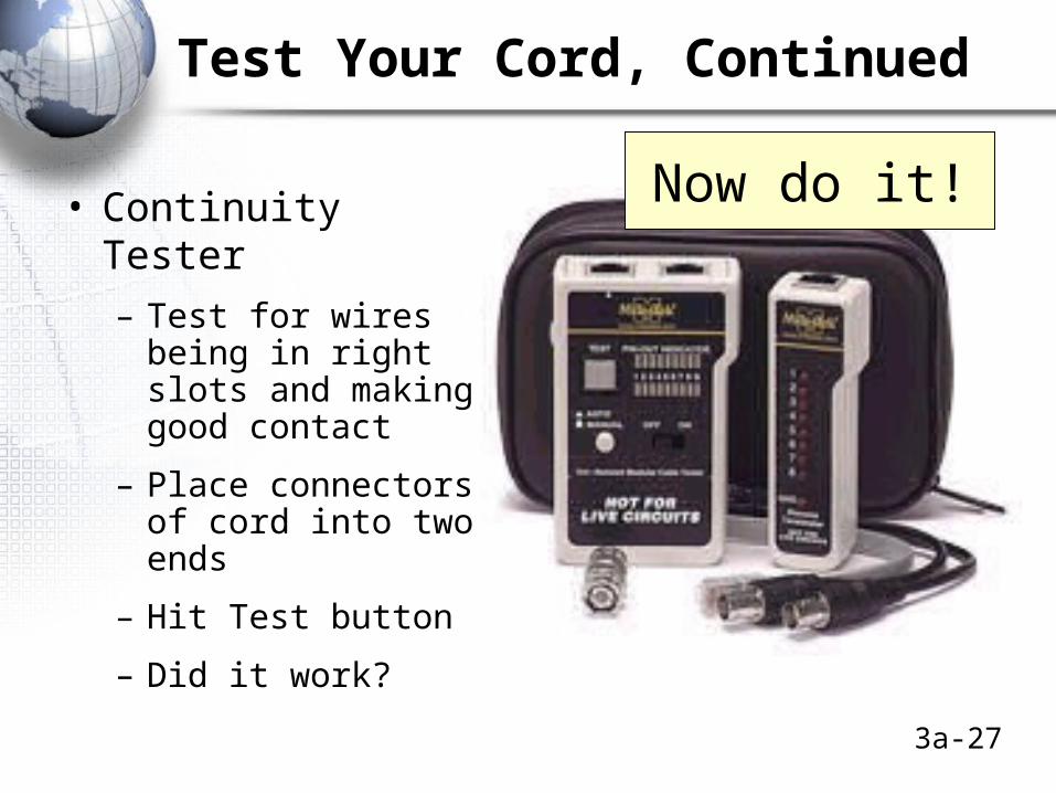
Test Your Cord, Continued
• Continuity Tester
– Test for wires being in right slots and making good contact
– Place connectors of cord into two ends
– Hit Test button
– Did it work?
Now do it!
3a-28
Test Your Cord, Continued
• If It Didn’t Work
– Be sure you understand the problem
– If an open connection, one or more of the wires was not pushed all the way to the end or the crimping did not push the pin all the way through the insulation. Next time, cut the wires straight across and crimp very firmly
– If miswired, see where it was miswired
– Cut off the ends of the cord and reconnectorize
Now do it!
3a-29
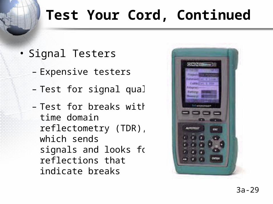
Test Your Cord, Continued
• Signal Testers
– Expensive testers
– Test for signal quality
– Test for breaks withtime domain reflectometry (TDR), which sendssignals and looks forreflections thatindicate breaks