Embed Size (px)
Citation preview
Hardware Implementation of an Iterative
Receiver for MIMO-OFDM Systems(first version)
Laurent Boher, Rodrigue Rabineau and Maryline Helard
France Telecom Research& Development Division, RESA/BWA
4 rue du Clos Courtel, B.P. 59, 35512 Cesson-Sevigne Cedex,France;
E-mail : [laurent.boher;rodrigue.rabineau;maryline.helard]@orange-ftgroup.com
Abstract
Today iterative receivers have proved their efficiency in cancelling interference in the field
of wireless communications. However their complexity is often presented as a brake for their use
in real systems. In this paper an efficient hardware implementation of an iterative receiver for a
4 × 4 MIMO system is presented. An architecture of MMSE iterativereceiver for MIMO-OFDM
systems is proposed to limit latency and complexity of the iterative process: MMSE equalization
implementation is realized thanks to CORDIC operators; thescheduling between MIMO detection
and channel decoding is optimized and specific interleavingfunctions are introduced to reduce latency
and accelerate the convergence process. The implemented receiver is integrated in an hardware
testbench and compared in terms of complexity and performance with a non iterative solution.
Index Terms
MIMO-OFDM systems, iterative receiver, hardware implementation
June 29, 2007 DRAFT

1
I. I NTRODUCTION
The next generation of wireless communication systems callfor new advanced techniques in
order to support ever-increasing data rates. By exploiting spatial diversity, multiple input mul-
tiple output (MIMO) systems position themselves as a serious candidate to increase spectral
efficiency as demonstrated in [1], [2]. From spatial multiplexing to space time block coding
(STBC) a large range of systems is available with a flexible trade off between spatial diversity
exploitation and data rate. Likewise, OFDM is a widely used solution for high-speed wireless
communications thanks to robustness against multi-path fading by eliminating intersymbol
interference (ISI) [3]. The combination of MIMO and OFDM presents significant interest
for high data rate wireless communications. Their association allows the receiver to only
deal with co-antenna interference. In this context, iterative receivers have been demonstrated
to efficiently deal with the presence of co-antenna interference [4]. In spite of their good
performance, iterative receivers are not yet widely used because of a high complexity induced
by both a complex MIMO detection and a costly iterative process.
Firstly, solutions have to be found to limit complexity of MIMO detection, where the
channel is represented by a matrix instead of a single channel coefficient in a SISO case.
Optimal maximum mikelihood (ML) algorithm has a complexityexponentially growing with
the MIMO architecture size and the modulation order. To limit the cost of the detection,
suboptimal approaches exist based on linear filtering (MMSE, ZF) or sphere decoding. How-
ever these solutions have often to deal with matrix inversion or triangularization in order to
calculate the filters [5], [6] or to pretreat the received signal [7], [8]. So complexity remains
in the treatment of the channel matrix. Several approaches exist to compute the required
matrix inversion, mainly based on QR decomposition. As these solutions suffer from a long
computation time, channel is often considered constant over several symbol times in order to
reuse the computed filter over several detection process andincrease achievable data rate.
Secondly, an architecture has to be found to realize the turbo-equalization process, where the
MIMO and the channel decoder exchange soft information to cancel co antenna interference.
The global scheduling of an iteration has to be optimized to limit latency of the reception
process. The fact that data are treated several times by MIMOdetection and MIMO decoding
imposes a long delay before detecting transmitted bits. Especially as only one processor
is generally implemented and reused for all iterations, this induces a limited data rate. To
be competitive, iterative receivers must be able to achieveequivalent data rate than system
June 29, 2007 DRAFT

2
without turbo-equalization.
In this paper, we presented the implementation of an iterative receiver for MIMO-OFDM
systems. MMSE interference cancellation is considered forMIMO detection and channel
coding is realized with a turbo code [9]. A specific attentionis paid to latency and convergence
optimization. A comparison is made between iterative and non iterative schemes in terms of
performance and complexity.
The paper is organized as follows. Section II describes the system model and the MIMO
iterative receiver structured on MMSE interference cancellation. In section III, the proposed
architecture of the receiver is detailed. We focus on the computation of MMSE filtering, the
definition of the exchange between MIMO and channel decodersand the optimization of the
interleaving functions. We describe the evaluation of the hardware implementation in section
IV: complexity and throughput figures are presented and performance are discussed. Finally,
conclusion is drawn in section VI.
II. SYSTEM MODEL
A. Transmitter
The considered MIMO-OFDM transmitter scheme that is presented on Figure 1 is the
typical space time bit interleaved coded modulation (ST-BICM) [10]. BICM [11], that is
well adapted to transmission over flat fading Rayleigh channels and to iterative process at
reception, is performed before the space time coding. Information bitsd are first encoded
with a convolutionnal turbo coder of rateR = 1/2 before being interleaved (Π). Groups of
b output bits are mapped on complex modulated symbolss. These symbols are then space
time encoded by groups ofQ symbols to produceXk ∈ CNT×T which represents thek-th
transmitted complex symbol matrix overT symbol durations. The rate of the space-time code
is defined to beRST = Q/T . Each elementxi,t of Xk represents the signal sent by theith
OFDM
OFDM
1
Mapping
s
Blockcoding
MIMOTurbo Coding
d
NT
Π
Fig. 1. MIMO transmission scheme
June 29, 2007 DRAFT

3
transmit antenna at timet. On each antenna elementsxi are at last OFDM modulated and
simultaneously transmitted.
B. Channel Model
We consider a discrete-time MIMO channel model withNT transmit antennas andNR
receive antennas. For a discrete-time representation of a time and frequency selective channel,
the frequency response of them-th subchannel between thei-th transmit antenna and thej-th
receive antenna can be expressed in a matrix form:
Hji,m =L−1∑
l=0
hji,le− j2πml
NFFT (1)
wherehji,l is a time varying channel tap,L the number of taps andNFFT the Fast Fourier
Transform (FFT) size. On the assumption of OFDM modulation and perfectly interleaved
subcarriers, each subcarrier channel coefficient can be considered as a flat-fading narrowband
subchannel that can be modelised by an uncorrelated complexGaussian law with unitary vari-
ance corresponding to a flat Rayleigh fading channel. By introducing an equivalent received
vector r ∈ CNRT×1, we can write:
r = Hs + n (2)
whereH ∈ CNRT×Q is the equivalent channel matrix considering a space time code transmit-
ting Q symbols overT symbols duration,s =[
s1 . . . sQ
]T
is the transmitted vector and
n ∈ CNRT×1 is the equivalent noise vector. In this paper we consider a system which can
treated space time codes associating until 4 symbols (Qmax = 4), such as spatial multiplexing
2x2 or 4x4, Alamouti 2x1, Double Alamouti 4x2...
C. MMSE iterative receiver
At the reception, after OFDM demodulation on each antenna, received symbols are treated
by the MIMO iterative receiver (Fig. 2). The receiver is composed of a MIMO decoding stage
and a channel decoding stage which exchange soft information on coded bits according to
turbo equalization principle [12]. We consider in this paper a solution based on MMSE linear
filtering and interference cancellation to obtain a receiver with a reduced complexity. The
MIMO decoding stage mainly consists in a MIMO equalizer thatproduces equalized vector
of transmitted symbolss deduced from received signalr and estimated symbolss. Owing
June 29, 2007 DRAFT

4
EqualizationMMSE−IC
MIMO decoding stage
1 MIMODemapping
Mapping
DecodingTurbo
Channel decoding stage
OFDM
OFDM
r
s
sNR
Π−1
Π
d
−1
−1
Fig. 2. MIMO iterative receiver scheme
to these estimated symbols, soft interference cancellation and MMSE filtering are performed
[13].
The output of the MMSE interference canceller (IC) can be expressed as:
sk = pHk r − qH
k sk (3)
where sk is an estimate ofsk with the k-th term equal to zero provided by the previous
iteration. The two vectorspk and qk are respectivelyNR × 1 and Q × 1 complex vectors
optimized under the MMSE criterion:
(poptk ,qopt
k ) = arg minpk,qk
|sk − sk|2 (4)
Since no prior information on transmitted symbols is available at the first iteration, the
equalization process is therefore reduced to a classical linear MMSE solution:
sMMSE =[
HHH +σ2
n
σ2s
I]−1
HH r (5)
where σ2n and σ2
s respectively correspond to the noise power and the signal power. Each
equalized symbolsk is associated to a biasβk used to correctly perform soft demapping in
order to obtain LLRΛeq[i, k] on the coded bits which can be directly used in the channel
decoding:
Λeq[i, k] = ln
∑
s∈X i1
exp(
− |sk−βks|2
(1−βk)βk
)
∑
s∈X i0
exp(
− |sk−βks|2
(1−βk)βk
)
(6)
This bias computed at the same time that MMSE filter is determined by:
βk = diagk
(
[
HHH +σ2
n
σ2s
I
]−1
HHH
)
(7)
June 29, 2007 DRAFT

5
where diagk(A) stands for thek-th diagonal element of the matrixA. We can notice that
this bias is not a complex but a real number.
For next iterations, coefficients of filters depend on estimated symbolssk. Exact solution
of the calculation of these filters can be found in [14], [15].However, as each filter has to
be determined by matrix inversion, the optimum receiver would induce a high complexity as
new filters have to be computed for each symbol.
In order to reduce complexity, a first approximation consists in selecting a filter constant
for all symbols of a ST block. In that case, filters are computed from the varianceσ2s of
estimated signals (MMSE-IC):
pMMSE−ICk =
σ2s pk
σ2s + σ2
seTk HH pk
andqMMSE−ICk = HHpMMSE−IC
k (8)
with pk = σ2s
[
HHH(σ2s − σ2
s) + σ2nI]−1
HHek and ek is a Q × 1 vector with all elements
equal to0 excepted thek-th element that is equal to1.
This solution allows to reduce the number of filter to be computed but always imposes
a new filter calculation at each iteration. Both complexity and data rate being dramatically
affected in that case, a stricter approximation has been considered.
On the assumption of perfect estimation of transmitted symbol (i.e. sk = sk), an other
sub-optimal solution (MF-IC) corresponding to the matched filter can be performed [16].
Unbiased equalized symbols for iterationl are obtained by:
sl = HH r − ddiag(
HHH)
s(l−1) (9)
with ddiag(A) is the matrix containing the off-diagonal elements ofA.
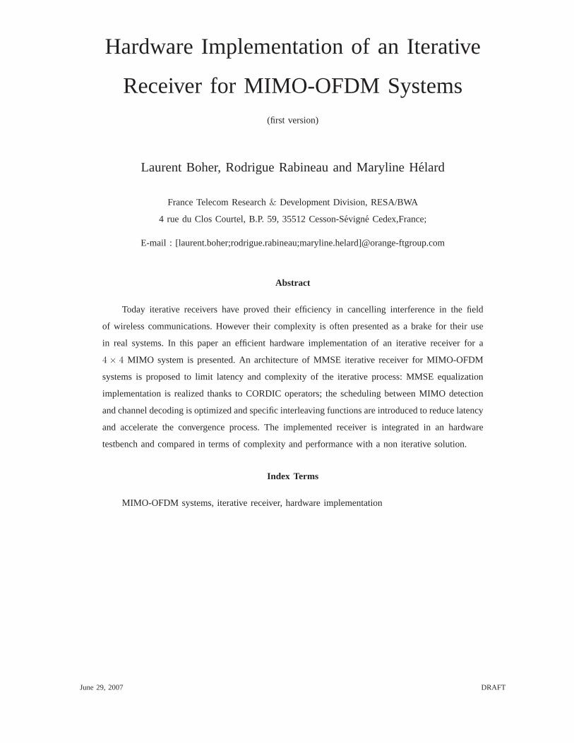
We can notice that with this last approximation no matrix inversion has to be performed
and the computation of filter coefficients has only to be done once per space-time block for
all iterations. Despite of this large approximation, performance are not significantly degrade
for a QPSK modulation, as exposed in Figure 3.
III. A RCHITECTURE DEFINITION
In this section, we detail the architecture proposed for receiver implementation. In a first
time, we describe how MMSE filtering is performed at the first iteration. Then, we concentrate
on how MIMO detection is updated along turbo decoding iterations. The scheduling of these
June 29, 2007 DRAFT
6
1.51.0 2.0 2.5 3.0 3.5 4.0 4.5 5.0 5.5 6.0−4
10
−3
10
−2
10
−1
10
0
10
Eb/No [dB]
BE
R
MF−IC #8(IC+TC)MMSE−IC #8(IC+TC)MMSE #8(TC)
4x4 Spatial multiplexing QPSK, Turbo codes K=3, packet size=1008 bits
Fig. 3. Performance evaluation of MIMO receiver for a 4x4 spatial multiplexed QPSK turbo-coded system over independent
flat Rayleigh channels. (IC+TC) corresponds to an iteration of interference cancellation and turbo decoding whereas (TC)
stands for an iteration of turbo decoding.
iterations imposes some constraints on the distance between interleaved bits. A solution of
interleaving respecting these constraints is finally described.
A. MMSE filter computation
The first step of an MIMO iterative receiver realization consists in efficiently performing the
first MIMO equalization. Indeed, MIMO MMSE filtering requires the resolution of a matrix
inversion which is a computationally challenging task (5).In order to implement this function,
the algorithmic solution must be numerically stable and usebasic operations. Calculating the
filtered vector thanks to CORDIC-based QR decomposition respects these two conditions.
1) MMSE filtering with QR decomposition
We consider here a solution where channel is updated at each time symbol. Sinace the
filter is used only once, it is more efficient to directly compute the filtered vector instead of
the filter.
The solution of the MMSE filtering can be viewed as the solution of a linear system:
Ax = b (10)
June 29, 2007 DRAFT

7
wherex =[
HHH + σ2n
σ2sI]−1
HHr is the equalized vector,A = HHH + σ2n
σ2sI is the matrix to
be inverted andb = HH r. In our context,A andb respectively belong toC4×4 andC4×1.
The QR factorization decomposes the matrixA in:
A = QR (11)
whereQ is an orthogonal matrix such thatQHQ = QQH = I andR is an upper triangular
matrix. Then the linear system (10) can be written as:
QRx = b (12)
The triangularization of the matrix is obtained by multiplying by QH :
Rx = QHb (13)
Finally, the filtered vector is obtained after a classical back substitution.
To obtain the final filtered vector, the bias of the equalizerβk has to be taken into account.
This bias is mathematically dependent on the inverse matrix. However this inversion is never
computed in the considered algorithm. Our investigation onsoft demapping led us to consider
this approximation of the bias, which degrades not significantly LLR information:
βk =diagk
(
HHH)
diagk
(
HHH)
+ σ2n
(14)
We can notice that the value ofHHH and HHr, which are needed for interference
cancellation at the following iterations, are already computed in the calculation of this first-
iteration filtered vector. Consequently, all calculations relative to the channel matrix are
computed before considering the channel decoding. Filter data required from the second
iteration of MIMO decoding are stored into memory until the end of the reception process.
2) Efficient QR decomposition with 6 CORDIC operators
The complexity and the latency of the filtering mainly dependon the triangularization
process. Efforts have to be put on the way QR decomposition isperformed. An efficient way
of triangularizing the matrix is to used Givens rotations, which allow to successively eliminate
under diagonal matrix terms. Systolic array have been demonstrated to be efficient for matrix
computation and particularly for QR factorization [17]. Weconsider here a QR-array where
processing elements are made with CORDIC functions [18]. The CORDIC algorithm actually
allows rotations on complex numbers to be performed in an iterative way with only basic
operators.
June 29, 2007 DRAFT

8
The challenging task of the triangularization implementation involves finding a compromise
between complexity and latency. An implementation of a complete QR-array allows a very-
high throughput but requires a large complexity (in calculation processors and pipelining
registers). In our case, 81 CORDIC operators would be required. To reduce this complexity,
calculation processors must be shared between several operations. Consequently a CORDIC
operator will be affected to several positions in the QR-array. We propose to carry out
QR decomposition thanks to 6 unrolled CORDIC (the intern iterative loop of the CORDIC
operator is unrolled) with 8 iterations of rotation computation. On the Figure 4, the map
of use of the 6 CORDIC operators in the QR-array is presented. In that case, the latency
of the QR decomposition is 76 clock cycles. By parallelize twoQR decompositions, a new
triangularization is enabled every 38 cycles. For more details about that architecture, the
reader could refer to [19].
Based on this 6-CORDIC QR decomposition, we have defined a4 × 4 MIMO equalizer
which processes the received vectorr, the channel matrixH and the noise varianceσ2n then
gives in output LLR on bits and matched filters data for the following iterations. Limited by
the latency of the QR decomposition, a new filtered vector is obtained every 38 clock cycles.
��������
��������
������
������
������
������
��������
��������
������
������
������
������
������
������
��������
��������
��������
��������
������
������
��������
������
������
������
������
��������
������
������
������
������
��������
��������
��������
������
������
������
������
������
������
������
������
��������
��������
��������
��������
������
������
��������
������
������
��������
��������
������
������
������
������
������
������
����������
����
������
��������
������
������
������
������
��������
��������
��������
��������
������
������
��������
������
������
��������
��������
������
������
������
������
������
������
������
��������������
��������
��������
������
������
transform in real the2nd element of the lines 2, 3 and 4
transform in real the4th element of the line
cancel the1st element of the lines 2, 3 and 4
cancel the2nd element of the lines 3 and 4
cancel the3rd element of the line 4
transform in real the3rd element of the lines 3 and 4
transform in real the1st element of the lines 2, 3 and 4
1st
colum
nofHH H
+σ2n
σ2s
I
3rd
colum
nofHH H
+σ2n
σ2s
I
4th
colum
nofHH H
+σ2n
σ2s
I
Hr
2nd co
lumn
ofHH H
+σ2n
σ2s
I
2nd CORDIC operator
3rd CORDIC operator
4th CORDIC operator
5th CORDIC operator
6th CORDIC operator
1st CORDIC operator
Fig. 4. The 81 complex rotations required in the QR decomposition are performed by 6 CORDIC operators. Here is the
map of reuse of these 6 operators to perform the rotations according to the line and the column to be treated and to the
phase in the QR decomposition
June 29, 2007 DRAFT
9
B. Sequencing
Thanks to the proposed MIMO equalizer, all filter data required to perform interference
cancellation are available after the first equalization. A scheduling is now required to determine
how channel decoding and MIMO decoding exchange information. Separately considering the
two decoders would induce a high latency of the reception process and so reduce data rate.
The total time of processing would actually be the addition of MIMO decoding duration and
channel decoding duration multiplied by the number of iterations. Moreover, the activities of
the two decoders would not be efficient as one decoder is sleeping when the other is working.
In order to optimize the activity of the two decoders, channel decoding and MIMO decoding
are performed in parallel. Each LLR entering the channel decoder is previously computed
by MIMO decoder. In the MIMO-OFDM case, LLRs obtained by nterference cancellation
are easily performed with information on the groups ofQb bits transmitted through the same
space time block. So at each clock cycle,Qb previously decoded bits (and the associated
filter coefficients) are used to compute the bit entering the channel decoder.
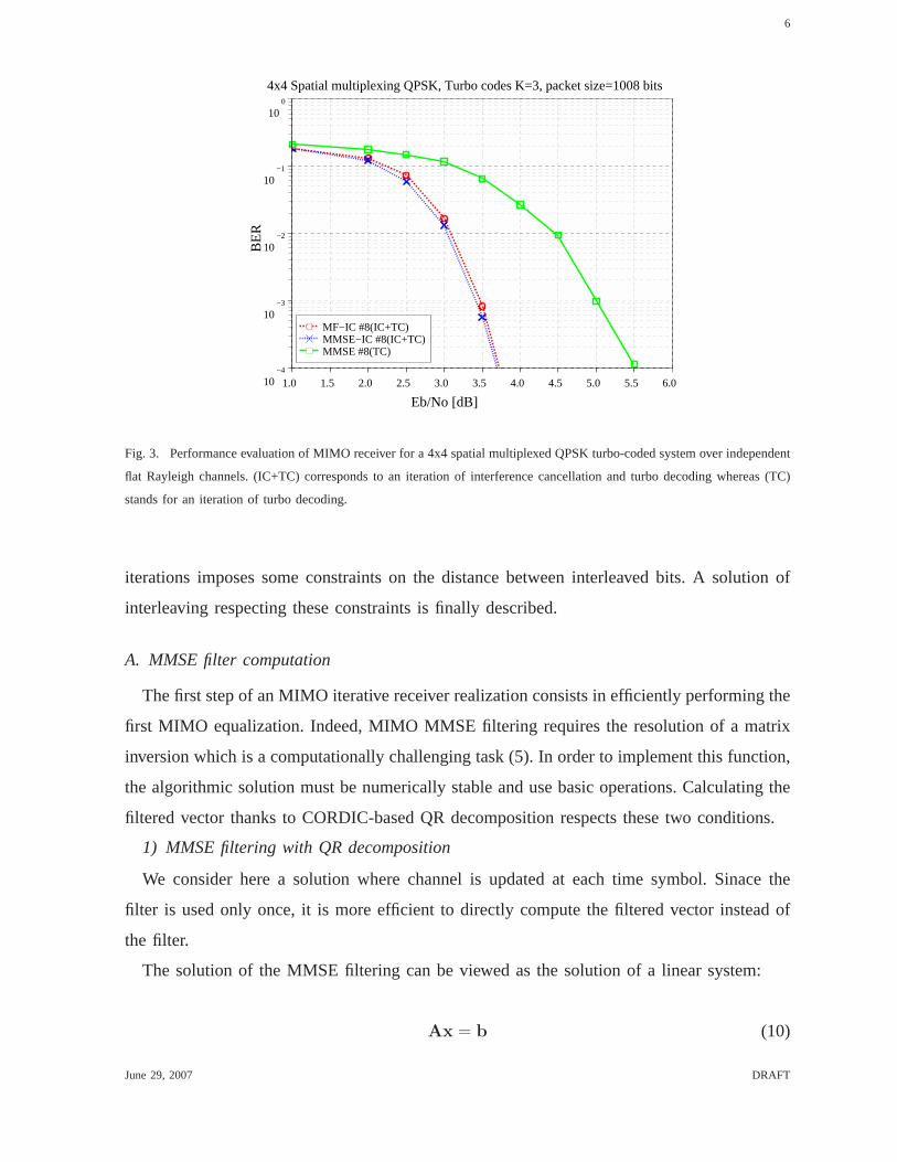
As the bit entering the decoder is computed by the MIMO updateprocessor just before
being processed by the channel decoder, it is possible to benefit from the bits previously
decoded in the same iteration (cf. Fig. 5). By this way, the exchange of information is more
efficient and thus the receiver requires less iterations to converge. The convergence gain of
this scheduling is exposed in [20] and [21].
In order to benefit from previously decoded bits, the bit we update must be sufficiently
separated from these previously decoded bits in the decoding trellis. As there is a delay
between the time a bit enters the channel decoder and the timeit is decoded, if two bits
from the same space time block are too close in the frame the first bit may not be decoded
when the second will enter the decoder. In that case, it will be impossible to use decoded
information of the first bit to update MIMO decoding of the second one. The distance after
interleaving between the bits of a same space time block has the be taken into account in the
definition of the interleaving function between channel andMIMO decoders.
When turbo codes are used as channel coding, two trellis have to be computed by iteration
of channel decoding. These two trellis are separated by an intern interleaver. An efficient use
of previously decoded bits in MIMO decoding goes through defining the extern interleaver
(between MIMO and channel decoders) in function of the intern interleaver of the turbo
decoder. In that way, the minimum distance between two bits of the same space time block
June 29, 2007 DRAFT

10
���
���
���
���
���
���
����
����
���
���
���
���
���
���
����
processor
MIMO decodingupdate
iteration i
iteration i−1 iteration i−1
iteration i
Classical Scheduling Proposed Scheduling
processor
MIMO decodingupdate
time time decoded by the channel decoder and used to update MIMO equalization
Bit transmitted through the considered space time blockentering the channel decoder
Bit transmitted through the considered space time blockdecoded by the channel decoder
the considered space time blockBit transmitted through
decoded bits at theith iteration
at theith iteration
decoded bits at theith iteration
decoded bits at the(i − 1)th iterationdecoded bits at the(i − 1)th iteration
bits entering channel decoding at the(i − 1)th iterationbits entering channel decoding at the(i − 1)th iteration
at theith iterationbits entering channel decoding bits entering channel decoding
Fig. 5. Schedulings of MIMO decoding update. Each bit entering channel decoder is calculated thanks to the 4 channel
decoded bits transmitted through the same space time block. In the classicalway, only decoded bits from the previous
iteration are used, whereas in the other scheduling bits previously decoded in the same iteration are used for updating
MIMO decoding
will be respected for the two decoding trellis.
C. Intern and extern interleaving
In order to respect the constraints of our scheduling, we define the extern interleaver in
function of the intern interleaver. Our investigation on interleaving functions led us to use the
structure described in [22] for the two interleaving functions. We first briefly describe this
structure, then we expose how it allows our constraints to berespected.
1) Interleaver definition
The interleaver can be described by four successive permutation laws. First the frame of
K = mz elements is interleaved by az-row m-column permutation. This permutation can be
expressed by:
Π1(i) = (i mod m) z +
⌊
i
m
⌋
(15)
In a second time, each groupk, k ∈ [0,m − 1] of z elements is right circularly shifted by
δ(k) positions, corresponding to the following permutation law:
Π2(i) =
(
δ
(⌊
i
z
⌋)
+ i
)
mod z +
⌊
i
z
⌋
z (16)
Then, the groups ofz elements are interleaved: the group in positionk becomes the group
in position P (k). The last step of the interleaving process consists in am-row z-column
June 29, 2007 DRAFT

11
permutation, dual to the first one. The resulting permutation law is then described by:
Πtot(i) = P (i mod m) + m
(
δ (i mod m) +
⌊
i
m
⌋)
mod z (17)
The whole interleaver is characterized thanks to2m+2 parameters:m, z, P (k) andδ(k) for
k ∈ [0,m − 1].
The interleaver can also be described using a matrix of sizeK × K:
Π = USU (18)
where theK ×K matrix U represents thez-row m-column permutation andU its dual. The
matrix S of size K × K is composed ofm circularly right shiftedz × z identity matrices.
Considering am × m matrix, identity matrix of linek is permuted byδ(k) positions and
located in theP (k) column. For instance, if we consider the following parameters: m = 3,
z = 4, P = [1; 0; 2] andδ = [1; 3; 0], matrix S is:
S =
0 0 0 0 0 1 0 0 0 0 0 0
0 0 0 0 0 0 1 0 0 0 0 0
0 0 0 0 0 0 0 1 0 0 0 0
0 0 0 0 1 0 0 0 0 0 0 0
0 0 0 1 0 0 0 0 0 0 0 0
1 0 0 0 0 0 0 0 0 0 0 0
0 1 0 0 0 0 0 0 0 0 0 0
0 0 1 0 0 0 0 0 0 0 0 0
0 0 0 0 0 0 0 0 1 0 0 0
0 0 0 0 0 0 0 0 0 1 0 0
0 0 0 0 0 0 0 0 0 0 1 0
0 0 0 0 0 0 0 0 0 0 0 1
2) Construction of an interleaver couple
We consider both intern and extern interleavers with the presented structure. In [22],
advantages of this interleaver structure for implementation of turbo decoding are presented.
Consequently, we focus on how it allows easily to spread, in the trellis, bits from a same
space time block.
In a first time, an interleaver is designed for the first (non intern interleaved) trellis. Channel
decoding is performed by Forward-Backward algorithm with a decoding window of size L
[23]. Designing the interleaver consists in choosing the parametersm, z, δ andP . m is fixed
as a multiple of the numberQb of bits from a space time block and we considerL = m. In
that case, to be sure that two bits from the same space time block will not be in decoding
process at the same time it is sufficient that they are separated from three decoding windows
June 29, 2007 DRAFT
12
b2
b3
b1
b2
b3
b1
b3
b2
b1
Time
bit positionInterleaver parametersChannel decoding process
−
−
−
−
−
−
−
−
−
−
−
−
−
−
−
−
−
5
−
−
−
−
−
−
−
2
−
8
−
−
−
−
−
−
−
−
−
−
−
−
−
7
−
−
−
−
−
−
3
−
−
−
−
−
−
0
−
−
−
6
−
−
−
−
−
−
−
4
−
−
−
−
−
−
−
−
−
−
−
−
1
b2
b3
b1
Channel decoder
MIM
O d
ecod
er
backward process
forward process
outputcalculation
m=9, z=9δ=[3,6,0,1,7,4,8,5,2]P=[4,8,6,1,5,7,3,0,2]
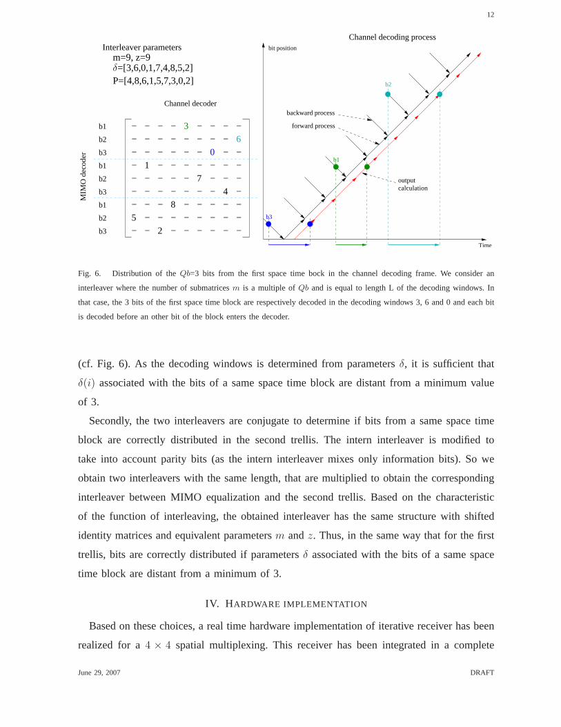
Fig. 6. Distribution of theQb=3 bits from the first space time bock in the channel decoding frame. We consider an
interleaver where the number of submatricesm is a multiple ofQb and is equal to length L of the decoding windows. In
that case, the 3 bits of the first space time block are respectively decoded in the decoding windows 3, 6 and 0 and each bit
is decoded before an other bit of the block enters the decoder.
(cf. Fig. 6). As the decoding windows is determined from parametersδ, it is sufficient that
δ(i) associated with the bits of a same space time block are distant from a minimum value
of 3.
Secondly, the two interleavers are conjugate to determine if bits from a same space time
block are correctly distributed in the second trellis. The intern interleaver is modified to
take into account parity bits (as the intern interleaver mixes only information bits). So we
obtain two interleavers with the same length, that are multiplied to obtain the corresponding
interleaver between MIMO equalization and the second trellis. Based on the characteristic
of the function of interleaving, the obtained interleaver has the same structure with shifted
identity matrices and equivalent parametersm andz. Thus, in the same way that for the first
trellis, bits are correctly distributed if parametersδ associated with the bits of a same space
time block are distant from a minimum of 3.
IV. H ARDWARE IMPLEMENTATION
Based on these choices, a real time hardware implementation of iterative receiver has been
realized for a4 × 4 spatial multiplexing. This receiver has been integrated ina complete
June 29, 2007 DRAFT

13
��������
��������
LLR
MMSE MIMO Equalizer Iterative Channel Decoder
QR
Decomposition
PrecomputationMatrix
SubstitutionBack
Demapping
MIMO DecodingUpdate
Processor
Equal.
Forward−BackwardProcessor Ext.
Decoded LLR
Matched FilterStored Data
Turbo−equalization additional components
permutation networks
1st
H r σ2n HHr
HHr HHH + σ2nI
HHH
Fig. 7. Architecture of the implemented MIMO iterative receiver
hardware transmission testbench in order to evaluate its performance.
A. Implemented receiver
The functional scheme of the receiver is depicted in Figure 7. The MIMO equalizer
component is composed of four functions (matrix precomputation, QR decomposition, back
substitution and demapping) which generates equalized LLRand matched filter coefficients.
LLR are stored in a first RAM to be used by channel decoder at the first iteration while filter
coefficients are stored in an other RAM to be used in the next iterations. The channel decoder
component is composed of two processors: one processor decodes the trellis thanks to the
Forward-Backward algorithm, the other computes LLR by MIMO decoding update. At these
two processors, we add four RAMs containing first-iteration LLR, up-to-date decoded LLR,
matched filter coefficients and extrinsic information on systematic bits. Exchanges between
the two processors and the four RAMs are controlled by two types of permutation network
depending on intern interleaving law for the extrinsic RAM and intern and extern interleaving
laws for the other RAMs. Without turbo-equalization, the channel decoder will only contain
a Forward-Backward porcessor, the extrinsic RAM and the first-iteration LLR RAM.
June 29, 2007 DRAFT

14
fading channels
4x4 MIMOflat Rayleigh
TurboCoding Mapping
BER Analyzer
MMSEDetector
4x4 MIMO
SourceRandom
IterativeChannelDecoder
Π
r
H
σ2n
Fig. 8. FPGA MIMO4× 4 evaluation testbench
B. An hardware evaluation testbench
The hardware evaluation testbench is depicted in Figure 8. This bench contains a transmitter,
a channel and a receiver all developed in VHDL and implemented into the same FPGA. In
order to have perfect estimated channel matrix and noise variance, a4 × 4 flat Rayleigh
fading channel has been developed using gaussian generators as defined in [24]. The channel
coefficients are updated at each symbol time.
The 4 × 4 channel is composed of 16 randomly generated coefficients inthe case of a
4×4 spatial multiplexing. In order to evaluate other MIMO schemes, channel coefficients are
repeated, modified or cancelled. Thus, all MIMO systems which can be expressed as a space
time coding withQ = NRT = 4 (that means the modified matrix channelH is in C4×4) can
be tested.
C. Rate analysis
The MMSE MIMO equalizer and the iterative channel decoder have been implemented
separately and each one has its own data rate.
The MIMO equalizer realizes a new equalization each 38 clockcycles. If we consider a
QPSK modulation on the 4 symbols of a space time block the maximal throughput of the
component is given by:
DMMSE =Qb
38fclk =
8
38fclk (19)
As we consider a half rate channel coding the maximal data rate on information bits for
the equalizer is soDinfoMMSE = 4
38fclk. For a 16QAM modulation the number of bits by symbol
June 29, 2007 DRAFT
15
MMSE EqualizerDecoder p=1Decoder p=2
1 2 3 4 5 6 7 8 9 100
10
20
30
40
50
60
iteration
Dat
a ra
te (
Mbi
ts/s
)
QPSK, K=896 bitsfclk = 50 MHz
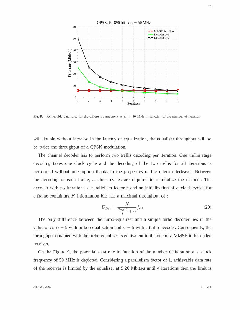
Fig. 9. Achievable data rates for the different component atfclk =50 MHz in function of the number of iteration
will double without increase in the latency of equalization, the equalizer throughput will so
be twice the throughput of a QPSK modulation.
The channel decoder has to perform two trellis decoding per iteration. One trellis stage
decoding takes one clock cycle and the decoding of the two trellis for all iterations is
performed without interruption thanks to the properties ofthe intern interleaver. Between
the decoding of each frame,α clock cycles are required to reinitialize the decoder. The
decoder withnit iterations, a parallelism factorp and an initialization ofα clock cycles for
a frame containingK information bits has a maximal throughput of :
DDec =K
2nitKp
+ αfclk (20)
The only difference between the turbo-equalizer and a simple turbo decoder lies in the
value ofα: α = 9 with turbo-equalization andα = 5 with a turbo decoder. Consequently, the
throughput obtained with the turbo-equalizer is equivalent to the one of a MMSE turbo-coded
receiver.
On the Figure 9, the potential data rate in function of the number of iteration at a clock
frequency of 50 MHz is depicted. Considering a parallelism factor of 1, achievable data rate
of the receiver is limited by the equalizer at 5.26 Mbits/s until 4 iterations then the limit is
June 29, 2007 DRAFT
16
MMSE MIMO Receiver Iterative MIMO receiver
Logic El. Memory bits 9x9 Mult. Logic El. Memory bits 9x9 Mult.
MMSE Equalization 8670 4750 16 9293 8464 16
Iterative Decoder p=2 4910 236160 0 8123 1303808 32
Total Receiver 13580 240912 16 17416 1312272 48
Total Chain 18338 361936 40 22173 1433296 72
FPGA Capacity 79040 7427520 176 79040 7427520 176
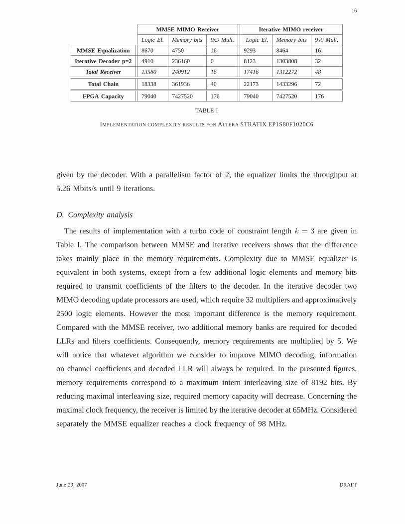
TABLE I
IMPLEMENTATION COMPLEXITY RESULTS FORALTERA STRATIX EP1S80F1020C6
given by the decoder. With a parallelism factor of 2, the equalizer limits the throughput at
5.26 Mbits/s until 9 iterations.
D. Complexity analysis
The results of implementation with a turbo code of constraint length k = 3 are given in
Table I. The comparison between MMSE and iterative receivers shows that the difference
takes mainly place in the memory requirements. Complexity due to MMSE equalizer is
equivalent in both systems, except from a few additional logic elements and memory bits
required to transmit coefficients of the filters to the decoder. In the iterative decoder two
MIMO decoding update processors are used, which require 32 multipliers and approximatively
2500 logic elements. However the most important differenceis the memory requirement.
Compared with the MMSE receiver, two additional memory banksare required for decoded
LLRs and filters coefficients. Consequently, memory requirements are multiplied by 5. We
will notice that whatever algorithm we consider to improve MIMO decoding, information
on channel coefficients and decoded LLR will always be required. In the presented figures,
memory requirements correspond to a maximum intern interleaving size of 8192 bits. By
reducing maximal interleaving size, required memory capacity will decrease. Concerning the
maximal clock frequency, the receiver is limited by the iterative decoder at 65MHz. Considered
separately the MMSE equalizer reaches a clock frequency of 98 MHz.
June 29, 2007 DRAFT
17
0 1 2 3 4 5 6 7 8 9 10−6
10
−5
10
−4
10
−3
10
−2
10
−1
10
0
10
PE
R
4x4 Spatial Multiplexing, QPSK, packet size=896 bits
PE
R
0 1 2 3 4 5 6 7 8 9 10−6
10
−5
10
−4
10
−3
10
−2
10
−1
10
0
10
Eb/N0Eb/N0
a) 4−state Turbo codes a) 8−state Turbo codes
AWGN #8(TC)
#8 (IC+TC)#4 (IC+TC)#2 (IC+TC)#8 (TC)#4 (TC)#2 (TC)
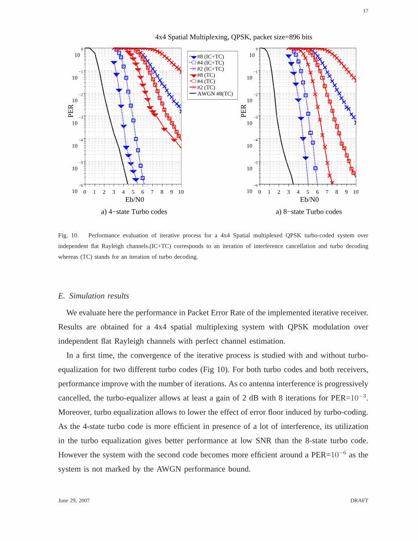
Fig. 10. Performance evaluation of iterative process for a 4x4 Spatialmultiplexed QPSK turbo-coded system over
independent flat Rayleigh channels.(IC+TC) corresponds to an iteration of interference cancellation and turbo decoding
whereas (TC) stands for an iteration of turbo decoding.
E. Simulation results
We evaluate here the performance in Packet Error Rate of the implemented iterative receiver.
Results are obtained for a 4x4 spatial multiplexing system with QPSK modulation over
independent flat Rayleigh channels with perfect channel estimation.
In a first time, the convergence of the iterative process is studied with and without turbo-
equalization for two different turbo codes (Fig 10). For both turbo codes and both receivers,
performance improve with the number of iterations. As co antenna interference is progressively
cancelled, the turbo-equalizer allows at least a gain of 2 dBwith 8 iterations for PER=10−3.
Moreover, turbo equalization allows to lower the effect of error floor induced by turbo-coding.
As the 4-state turbo code is more efficient in presence of a lotof interference, its utilization
in the turbo equalization gives better performance at low SNR than the 8-state turbo code.
However the system with the second code becomes more efficient around a PER=10−6 as the
system is not marked by the AWGN performance bound.
June 29, 2007 DRAFT

18
2 3 4 5 6 7 8 9 10−6
10
−5
10
−4
10
−3
10
−2
10
−1
10
0
10
Eb/N0 [dB]
PE
R
2 3 4 5 6 7 8 9 10−6
10
−5
10
−4
10
−3
10
−2
10
−1
10
0
10
PE
R
Eb/N0 [dB]
b) MMSE MIMO receivera) Iterative MIMO receiver
4x4 Spatial Multiplexing, QPSK, 4−state TC , packet size=896 bits
#8 float#6 float#4 float#2 float#8 fixed#6 fixed#4 fixed#2 fixed
Fig. 11. Performance evaluation of degradation induced by implementation constraints. Floating point simulation are
compared with results obtained with the hardware testbench for the proposed iterative receiver (a) and a MMSE receiver
(b).
Secondly, the degradation of performance induced by approximation on the parameterβ
and quantification is evaluated. Thus, we compared performance obtained with a floating
point of the algorithm and with the hardware testbench on Figure 11. Small degradations
are noticed, especially in the turbo equalization case. Effects of quantification are the most
important in MMSE filtering, LLR obtained after the first equalization are so largely degraded.
In the iterative case, these LLRs are used only in the first iteration of channel decoding the
degradation they induce reduces with the number of iterations. In the other case, these LLRs
are used for all iterations of turbo decoding, the quantification is so more degrading.
Finally, influence of interleaving is studied in Figure 12. As expected performance improve
with the length of interleaver as data are more decorrelated. Moreover, the design of the
interleaver (and the associated scheduling) has an influence on the convergence of the system.
The proposed interleaving allows to spread bits from a same space time block and benefit as
soon as possible from their decoding. When constraints are relaxed on the extern interleaver,
June 29, 2007 DRAFT

19
3.0 3.5 4.0 4.5 5.0 5.5 6.0−6
−5
−4
−3
−2
−1
10
10
10
10
10
10
100
PE
R
Eb/N0a) packet size = 896 bits b) packet size = 3584 bits
4x4 Spatial Multiplexing, QPSK, 4−state TC
#8 proposed interleaver#6 proposed interleaver#4 proposed interleaver#8 constraint free interleaver#6 constraint free interleaver#4 constraint free interleaver
3.0 3.5 4.0 4.5 5.0 5.5 6.0−6
−5
−4
−3
−2
−1
0
10
10
10
10
10
10
10
PE
R
Eb/N0
Fig. 12. Performance evaluation of interleaving properties. The turbo interleaver has a length equivalent to the packet size
and the MIMO interleaver is twice longer. An optimized interleaver couple is compared with an interleaver couple where
the constraints on the bits of a same ST block have been relaxed .
such that some bits cannot be used in the current iteration asthey are not yet decoded,
performance are slightly degraded. Thus, we see here the interest of the considered scheduling
that consists in updating MIMO decoding thanks to as many bits as possible decoded in the
current iteration.
V. CONCLUSION
In this paper, an efficient implementation of a MMSE iterative receiver for MIMO-OFDM
systems has been presented. An architecture is proposed to limit complexity and latency and
to accelerate convergence. MMSE equalization realized from QR decomposition is optimized
thanks to an efficient reuse of CORDIC operators. To reduce latency of the iterative process
MIMO detection and channel decoding are performed simultaneously and specific interleav-
ing functions are introduced to accelerate the convergenceprocess. The MIMO receiver is
composed of a MIMO equalizer that performs MMSE filtering forthe first iteration and
computes matched filter coefficients for next iterations, and an extended iterative decoder that
simultaneously computes channel decoding and MIMO decoding update. Thus, equivalent
June 29, 2007 DRAFT

20
throughput are obtained compared to a classical MMSE turbo-coded solution and complexity
surcharge mainly stands in filters memory requirements. Degradations induced by hardware
implementation are negligible and performance comparisonwith a MMSE receiver without
turbo-equalization shows a gain greater than 2dB for a 4x4 spatial multiplexing MIMO scheme
and a limitation of the error floor effect of turbo codes.
REFERENCES
[1] G. J. Foschini and M. J. Gans, “On limits of wireless communications ina fading environment when using multiple
antenna,”Wireless Pers. Commun., vol. 6, pp. 311–335, Mar. 1998.
[2] E. Telatar, “Capacity of multiantenna gaussian channel,”Bell Labs. Tech. Memo., June 1995.
[3] B. Le Floch, M. Alard, and C. Berrou, “Coded orthogonal frequency division multiplex,”Proceedings of the IEEE,
vol. 83, no. 6, pp. 982–996, June 1995.
[4] I. Lee, A. M. Chan, and C.-E. W. Sundberg, “Space-time bit interleaved coded modulation for OFDM system,”IEEE
Trans. Signal Processing, vol. 52, no. 3, pp. 820–825, Mar. 2004.
[5] B. Hassibi, “An efficient square-root algorithm for blast,” inProceedings of ICASSP’00, Istanbul, Turkey, June 2000,
pp. 737–740.
[6] M. Myllyla, J. Hintikka, J. Cavallaro, M. Juntti, M. Limingoja, and A. Byman, “Complexity analysis of MMSE detector
architectures for MIMO OFDM systems,” in39th Annual Asilomar Conference on Signals, Systems and Computer,
Pacific Grove, California, Oct. 2006, pp. 75–81.
[7] Z. Guo and P. Nilsson, “Algorithm and implementation of the k-best sphere decoding for MIMO detection,”IEEE J.
Select. Areas Commun., vol. 24, no. 3, pp. 491–503, Mar. 2006.
[8] F. Sobahnmanesh and S. Nooshabadi, “VLSI architecture for 4x4 16QAM V-BLAST decoder,”IRE Trans. Inform.
theory, vol. 37, pp. 10–21, 06.
[9] C. Berrou, A. Glavieux, and P. Thitimajshima, “Near shannon limit error-correcting coding and decoding: Turbo-codes,”
in Proceedings of ICC’93, Geneva, Switzerland, May 1993, pp. 1064–1070.
[10] A. M. Tonello, “Space-time bit-interleaved coded modulation with an iterative decoding strategy,” inProceedings of
VTC Fall’00, Boston, USA, Sept. 2000, pp. 473–478.
[11] G. Caire, G. Taricco, and E. Biglieri, “Bit-interleaved coded modulation,” IEEE Trans. Inform. Theory, vol. 44, pp.
927–945, May 1998.
[12] C. Douillard, A. Picart, P. Didier, M. Jezequel, C. Berrou, and A.Glavieux, “Iterative correction of intersymbol
interference: Turbo-equalization,”Eur. Trans. Telecommunications, vol. 6, no. 5, Sept. 1995.
[13] A. Glavieux, C. Laot, and J. Labat, “Turbo equalization over a frequency selective channel,” inProceedings of ISTC’97,
Brest, France, Sept. 1997, pp. 96–102.
[14] M. Witzke, S. Baro, F. Schreckenbach, and J. Hagenauer, “Iterative detection of MIMO signals with linear detectors,”
in Proceedings of Asilomar Conference, vol. 1, Pacific Grove, California, Nov. 2002, pp. 289–293.
[15] D. Reynolds and X. Wang, “Low complexity turbo-equalization for diversity channels,”Signal Processing, vol. 85,
no. 5, pp. 989–995, May 2001.
[16] P.-J. Bouvet, M. Helard, and V. Le Nir, “Low complexity iterative receiver for non-orthogonal space-time block code
with channel coding,” inProceedings of VTC Fall ’04, Los Angeles, USA, Sept. 2004.
June 29, 2007 DRAFT
21
[17] W. Gentleman and H. Kung, “Matrix triangularization by systolic array,” in Proceeding’s of SPIE Conf. on Real Time
Signal Processing, Harbor Springs, USA, aug 1981, pp. 19–26.
[18] J. Volder, “The CORDIC trigonometric computing technique,”IRE Trans. Electronic Computing, pp. 30–37, Sept.
1959.
[19] L. Boher, R. Rabineau, and M. Helard, “An efficient MMSE equalizer implementation for 4x4 MIMO-OFDM systems
in frequency selective fast varying channels,”accepted in PIMRC’07, Sept. 2007.
[20] L. Boher, M. Helard, and R. Rabineau, “MIMO iterative receiver with bit per bit interference cancellation,” in
Proceedings of ISWCS’06, Valencia, Spain, Sept. 2006.
[21] ——, “Turbo-coded MIMO iterative receiver with bit per bit interference cancellation for M-QAM gray mapping
modulation,” inProceedings of VTC Spring’07, Dublin, Ireland, Apr. 2007.
[22] L. Boher, J.-B. Dore, M. Helard, and C. Gallard, “Interleaver for high parallelizable turbo decoder,” in Proceedings of
MC-SS’07, Herrsching, Germany, May 2007.
[23] E. Boutillon, W. Gross, and P. Gulak, “VLSI architectures for the MAP algorithm,” IEEE Trans. Commun., vol. 51,
pp. 175–185, Feb. 2003.
[24] A. Ghazel, E. Boutillon, J. Danger, G. Gulak, and H. Laamari, “Design and performance analysis of a high speed
AWGN communication channel emulator,” inProceedings of PACRIM’01, Victoria, Canada, Aug. 2001, pp. 19–26.
June 29, 2007 DRAFT