Embed Size (px)
Citation preview
HDC-900-GPT Manual 08/2012
Copyright 2012 Vestil Manufacturing Corp.
HDC-900-GPT OPERATION & SERVICE MANUAL
Towable Hydraulic Drum Crusher
VESTIL MANUFACTURING CORP. 2999 NORTH WAYNE STREET, P.O. BOX 507, ANGOLA, IN 46703 TELEPHONE: (260) 665-7586 –OR- TOLL FREE: (800) 348-0868
FAX: (260) 665-1339
WEBSITE: WWW.VESTILMFG.COM EMAIL: [email protected]
Receiving Instructions: Each unit is thoroughly inspected prior to shipment. However, the compactor may sustain damage during transit. After the carrier delivers the product, remove all packaging material and inspect the unit for damage. If you notice damage, make note of it on the SHIPPER RECEIPT and FILE A CLAIM WITH THE CARRIER IMMEDIATELY.
Table of Contents Table of Figures Safety Principles…………………………… 2 Fig. 1 Hydraulic System Diagram…………………………………4 Safe Operation Recommendations ………… 2 Fig. 2 Electric System Diagram…………………………………...5 Product Introduction ………………………. 3 Fig. 3 Parts Diagrams……………...................................................6 - 14Functions Tests & Inspections………………15 - 16 Fig. 4 Emergency Stops………………………………………….. 15 Preparing for Operation …………………… 16 Fig. 5A & 5B Oil Reservoir………..…………………………….. 15 Operation……………………………………16 Fig. 6 Drum enclosure…………...................................................... 15 Inspections & Maintenance…………………19 Fig. 7 Compactor orientation control………..……………………. 16 Label Placement Diagram…………………. 20 - 21 Fig. 8 Stabilizing jacks storage & use……………………………..16 Limited Warranty…………………………... 22 Fig. 9 Gasoline motor……………………………………………... 17 Fig. 10 Auto cycle valve………………………………………….. 17 Fig. 11 Hydraulic oil fill cap……………………………………… 18
HDC-900-GPT Manual 08/2012
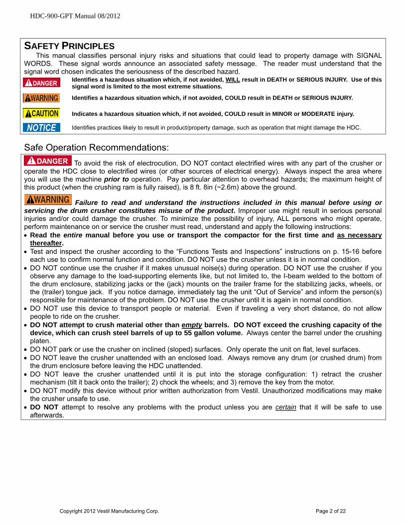
SAFETY PRINCIPLES This manual classifies personal injury risks and situations that could lead to property damage with SIGNAL
WORDS. These signal words announce an associated safety message. The reader must understand that the signal word chosen indicates the seriousness of the described hazard.
Identifies a hazardous situation which, if not avoided, WILL result in DEATH or SERIOUS INJURY. Use of this signal word is limited to the most extreme situations.
Identifies a hazardous situation which, if not avoided, COULD result in DEATH or SERIOUS INJURY.
Indicates a hazardous situation which, if not avoided, COULD result in MINOR or MODERATE injury. Identifies practices likely to result in product/property damage, such as operation that might damage the HDC.
Safe Operation Recommendations:
To avoid the risk of electrocution, DO NOT contact electrified wires with any part of the crusher or operate the HDC close to electrified wires (or other sources of electrical energy). Always inspect the area where you will use the machine prior to operation. Pay particular attention to overhead hazards; the maximum height of this product (when the crushing ram is fully raised), is 8 ft. 8in (~2.6m) above the ground.
Failure to read and understand the instructions included in this manual before using or servicing the drum crusher constitutes misuse of the product. Improper use might result in serious personal injuries and/or could damage the crusher. To minimize the possibility of injury, ALL persons who might operate, perform maintenance on or service the crusher must read, understand and apply the following instructions: Read the entire manual before you use or transport the compactor for the first time and as necessary
thereafter. Test and inspect the crusher according to the “Functions Tests and Inspections” instructions on p. 15-16 before
each use to confirm normal function and condition. DO NOT use the crusher unless it is in normal condition. DO NOT continue use the crusher if it makes unusual noise(s) during operation. DO NOT use the crusher if you
observe any damage to the load-supporting elements like, but not limited to, the I-beam welded to the bottom of the drum enclosure, stabilizing jacks or the (jack) mounts on the trailer frame for the stabilizing jacks, wheels, or the (trailer) tongue jack. If you notice damage, immediately tag the unit “Out of Service” and inform the person(s) responsible for maintenance of the problem. DO NOT use the crusher until it is again in normal condition.
DO NOT use this device to transport people or material. Even if traveling a very short distance, do not allow people to ride on the crusher.
DO NOT attempt to crush material other than empty barrels. DO NOT exceed the crushing capacity of the device, which can crush steel barrels of up to 55 gallon volume. Always center the barrel under the crushing platen.
DO NOT park or use the crusher on inclined (sloped) surfaces. Only operate the unit on flat, level surfaces. DO NOT leave the crusher unattended with an enclosed load. Always remove any drum (or crushed drum) from
the drum enclosure before leaving the HDC unattended. DO NOT leave the crusher unattended until it is put into the storage configuration: 1) retract the crusher
mechanism (tilt it back onto the trailer); 2) chock the wheels; and 3) remove the key from the motor. DO NOT modify this device without prior written authorization from Vestil. Unauthorized modifications may make
the crusher unsafe to use. DO NOT attempt to resolve any problems with the product unless you are certain that it will be safe to use
afterwards.
Copyright 2012 Vestil Manufacturing Corp. Page 2 of 22
HDC-900-GPT Manual 08/2012
P ODUCT INTRODUCTIONR
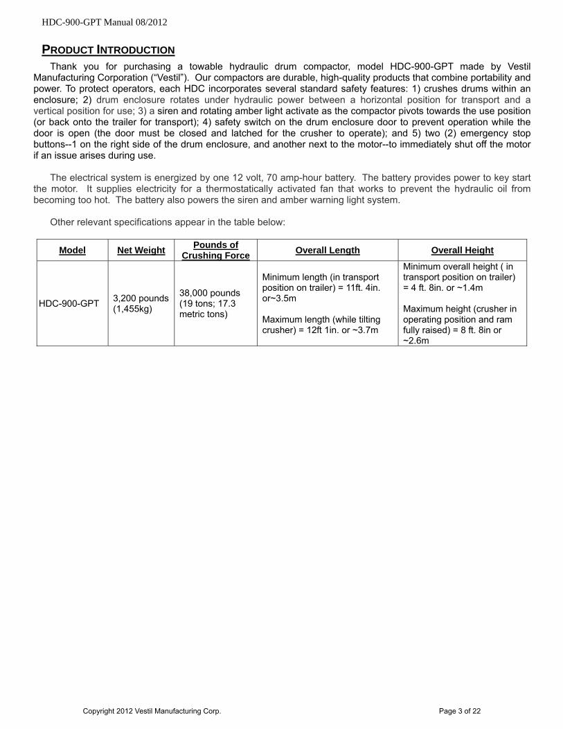
Thank you for purchasing a towable hydraulic drum compactor, model HDC-900-GPT made by Vestil Manufacturing Corporation (“Vestil”). Our compactors are durable, high-quality products that combine portability and power. To protect operators, each HDC incorporates several standard safety features: 1) crushes drums within an enclosure; 2) drum enclosure rotates under hydraulic power between a horizontal position for transport and a vertical position for use; 3) a siren and rotating amber light activate as the compactor pivots towards the use position (or back onto the trailer for transport); 4) safety switch on the drum enclosure door to prevent operation while the door is open (the door must be closed and latched for the crusher to operate); and 5) two (2) emergency stop buttons--1 on the right side of the drum enclosure, and another next to the motor--to immediately shut off the motor if an issue arises during use.
The electrical system is energized by one 12 volt, 70 amp-hour battery. The battery provides power to key start
the motor. It supplies electricity for a thermostatically activated fan that works to prevent the hydraulic oil from becoming too hot. The battery also powers the siren and amber warning light system.
Other relevant specifications appear in the table below:
Model Net Weight Pounds of
Crushing Force Overall Length Overall Height
HDC-900-GPT 3,200 pounds (1,455kg)
38,000 pounds (19 tons; 17.3 metric tons)
Minimum length (in transport position on trailer) = 11ft. 4in. or~3.5m Maximum length (while tilting crusher) = 12ft 1in. or ~3.7m
Minimum overall height ( in transport position on trailer) = 4 ft. 8in. or ~1.4m Maximum height (crusher in operating position and ram fully raised) = 8 ft. 8in or ~2.6m
Copyright 2012 Vestil Manufacturing Corp. Page 3 of 22
HDC-900-GPT Manual 08/2012
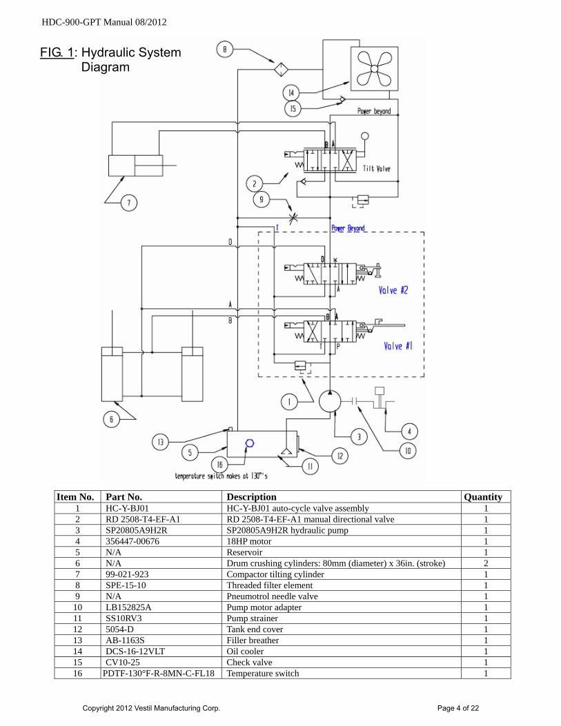
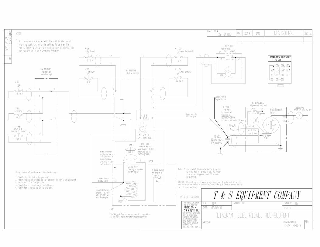
FIG. 1: Hydraulic System Diagram
Item No. Part No. Description Quantity 1 HC-Y-BJ01 HC-Y-BJ01 auto-cycle valve assembly 1 2 RD 2508-T4-EF-A1 RD 2508-T4-EF-A1 manual directional valve 1 3 SP20805A9H2R SP20805A9H2R hydraulic pump 1 4 356447-00676 18HP motor 1 5 N/A Reservoir 1 6 N/A Drum crushing cylinders: 80mm (diameter) x 36in. (stroke) 2 7 99-021-923 Compactor tilting cylinder 1 8 SPE-15-10 Threaded filter element 1 9 N/A Pneumotrol needle valve 1
10 LB152825A Pump motor adapter 1 11 SS10RV3 Pump strainer 1 12 5054-D Tank end cover 1 13 AB-1163S Filler breather 1 14 DCS-16-12VLT Oil cooler 1 15 CV10-25 Check valve 1 16 PDTF-130°F-R-8MN-C-FL18 Temperature switch 1
Copyright 2012 Vestil Manufacturing Corp. Page 4 of 22
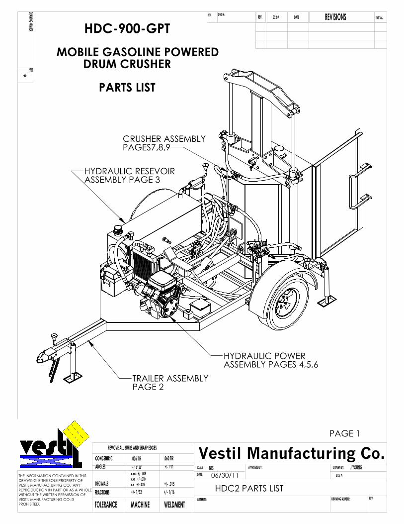
TRAILER ASSEMBLYPAGE 2
HYDRAULIC RESEVOIR ASSEMBLY PAGE 3
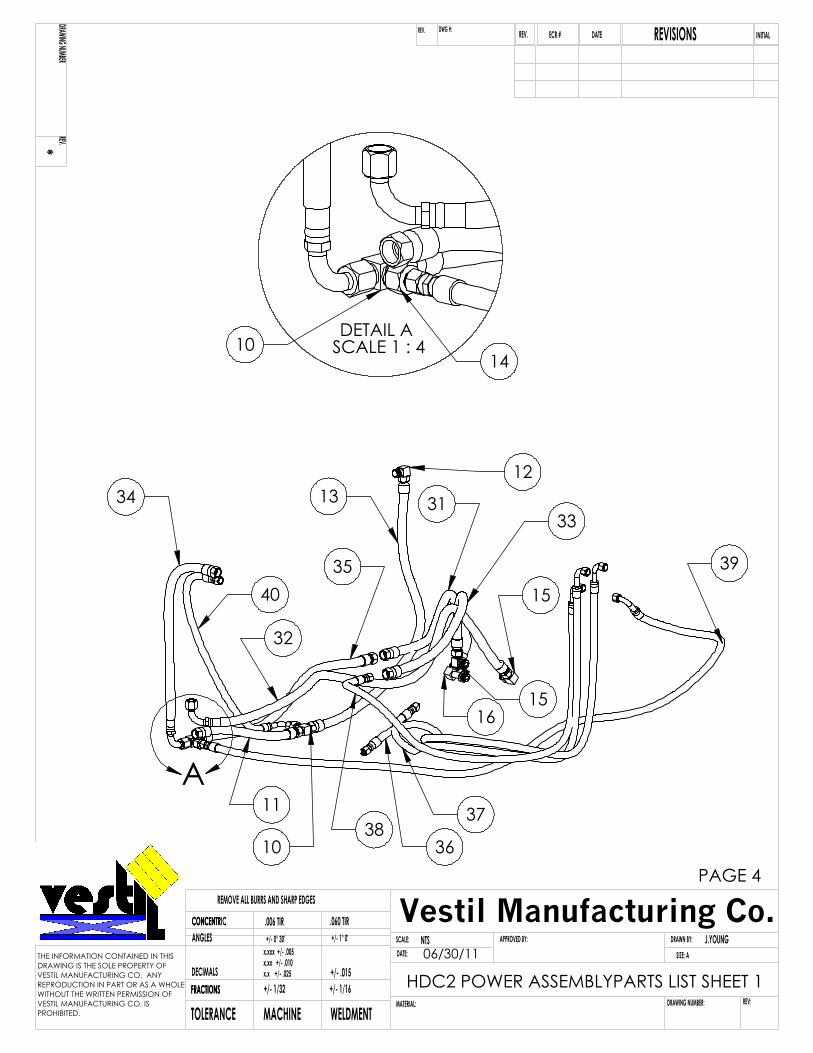
HYDRAULIC POWERASSEMBLY PAGES 4,5,6
CRUSHER ASSEMBLYPAGES7,8,9
HDC-900-GPTMOBILE GASOLINE POWERED DRUM CRUSHER
PARTS LIST
PAGE 1
NTS J.YOUNGSCALE:DATE:
APPROVED BY: DRAWN BY:
DRAWING NUMBER:MATERIAL:TOLERANCE MACHINE WELDMENTFRACTIONSFRACTIONSDECIMALS
ANGLESCONCENTRICCONCENTR
+/- 1/32 +/- 1/16+/- .015
.006 TIR .060 TIR
REMOVE ALL BURRS AND SHARP EDGES
x.x +/- .025x.xx +/- .010x.xxx +/- .005
+/- 0° 30' +/- 1° 0'
REV:
SIZE: A
*DRAWING NUMBER
REV.
DATE INITIALREVISIONSREV.DWG #:REV. ECR #
THE INFORMATION CONTAINED IN THISDRAWING IS THE SOLE PROPERTY OFVESTIL MANUFACTURING CO. ANY REPRODUCTION IN PART OR AS A WHOLEWITHOUT THE WRITTEN PERMISSION OFVESTIL MANUFACTURING CO. IS PROHIBITED.
Vestil Manufacturing Co.
HDC2 PARTS LIST06/30/11
5
41
2
6
83
7
9
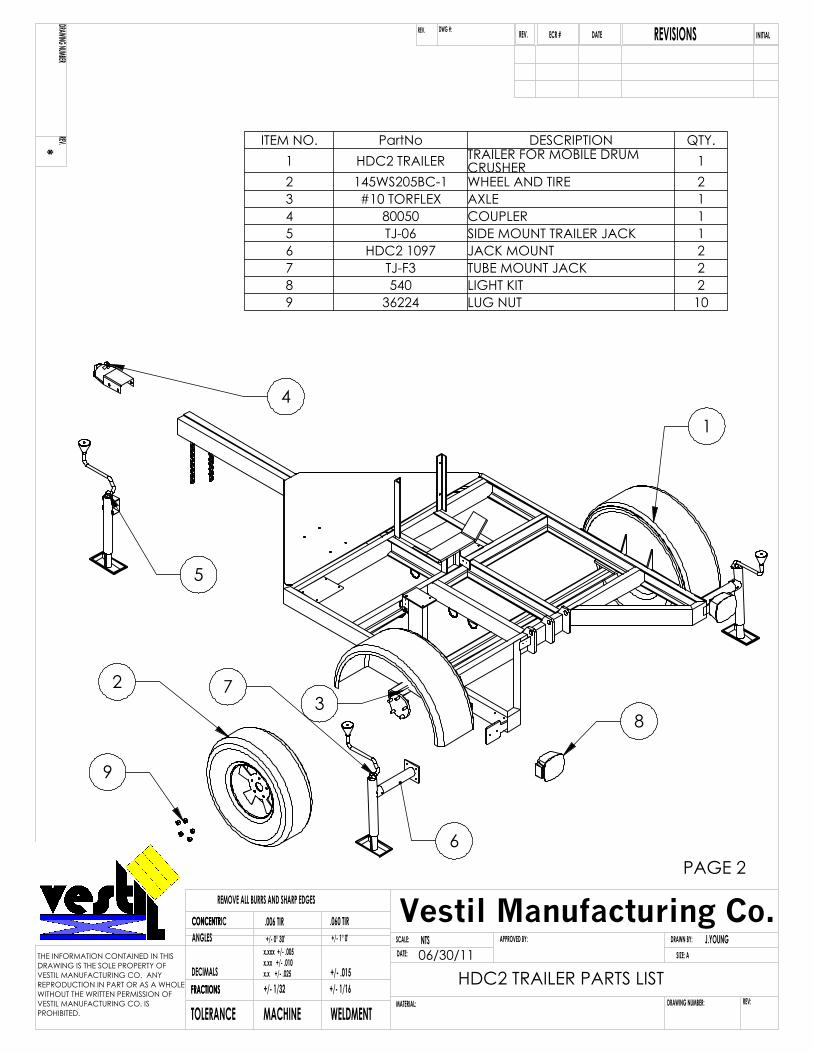
PAGE 2
ITEM NO. PartNo DESCRIPTION QTY.1 HDC2 TRAILER TRAILER FOR MOBILE DRUM
CRUSHER 12 145WS205BC-1 WHEEL AND TIRE 23 #10 TORFLEX AXLE 14 80050 COUPLER 15 TJ-06 SIDE MOUNT TRAILER JACK 16 HDC2 1097 JACK MOUNT 27 TJ-F3 TUBE MOUNT JACK 28 540 LIGHT KIT 29 36224 LUG NUT 10
NTS J.YOUNGSCALE:DATE:
APPROVED BY: DRAWN BY:
DRAWING NUMBER:MATERIAL:TOLERANCE MACHINE WELDMENTFRACTIONSFRACTIONSDECIMALS
ANGLESCONCENTRICCONCENTR
+/- 1/32 +/- 1/16+/- .015
.006 TIR .060 TIR
REMOVE ALL BURRS AND SHARP EDGES
x.x +/- .025x.xx +/- .010x.xxx +/- .005
+/- 0° 30' +/- 1° 0'
REV:
SIZE: A
*DRAWING NUMBER
REV.
DATE INITIALREVISIONSREV.DWG #:REV. ECR #
THE INFORMATION CONTAINED IN THISDRAWING IS THE SOLE PROPERTY OFVESTIL MANUFACTURING CO. ANY REPRODUCTION IN PART OR AS A WHOLEWITHOUT THE WRITTEN PERMISSION OFVESTIL MANUFACTURING CO. IS PROHIBITED.
Vestil Manufacturing Co.
HDC2 TRAILER PARTS LIST06/30/11
8
29
13
141
5
106
?
7
4
3 11
1216
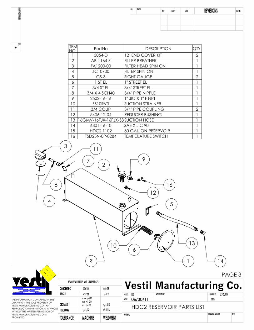
PAGE 3
06/30/11
ITEM NO. PartNo DESCRIPTION QTY.
1 5054-D 12" END COVER KIT 22 AB-1164-S FILLER BREATHER 13 FA1200-00 FILTER HEAD SPIN ON 14 ZC10700 FILTER SPIN ON 15 GS-3 SIGHT GAUGE 26 1 ST EL 1" STREET EL 17 3/4 ST EL 3/4" STREET EL 18 3/4 X 4 SCH40 3/4" PIPE NIPPLE 19 2502-16-16 1" JIC X 1" F NPT 1
10 SS10RV3 SUCTION STRAINER 111 3/4 COUP 3/4" PIPE COUPLING 212 5406-12-04 REDUCER BUSHING 113 16GMV-16FJX-16FJX-33SUCTION HOSE 114 6801-16-10 SAE X JIC 90 115 HDC2 1102 30 GALLON RESERVOIR 116 TSD25N-0P-0284 TEMPERATURE SWITCH 1
NTS J.YOUNGSCALE:DATE:
APPROVED BY: DRAWN BY:
DRAWING NUMBER:MATERIAL:TOLERANCE MACHINE WELDMENTFRACTIONSFRACTIONSDECIMALS
ANGLESCONCENTRICCONCENTR
+/- 1/32 +/- 1/16+/- .015
.006 TIR .060 TIR
REMOVE ALL BURRS AND SHARP EDGES
x.x +/- .025x.xx +/- .010x.xxx +/- .005
+/- 0° 30' +/- 1° 0'
REV:
SIZE: A
*DRAWING NUMBER
REV.
DATE INITIALREVISIONSREV.DWG #:REV. ECR #
THE INFORMATION CONTAINED IN THISDRAWING IS THE SOLE PROPERTY OFVESTIL MANUFACTURING CO. ANY REPRODUCTION IN PART OR AS A WHOLEWITHOUT THE WRITTEN PERMISSION OFVESTIL MANUFACTURING CO. IS PROHIBITED.
Vestil Manufacturing Co.
HDC2 RESERVOIR PARTS LIST06/30/11
A
1312
39
15
31
16
33
37
35
3638
10
32
11
40
34
15
PAGE 4
DETAIL A SCALE 1 : 4
1410
NTS J.YOUNGSCALE:DATE:
APPROVED BY: DRAWN BY:
DRAWING NUMBER:MATERIAL:TOLERANCE MACHINE WELDMENTFRACTIONSFRACTIONSDECIMALS
ANGLESCONCENTRICCONCENTR
+/- 1/32 +/- 1/16+/- .015
.006 TIR .060 TIR
REMOVE ALL BURRS AND SHARP EDGES
x.x +/- .025x.xx +/- .010x.xxx +/- .005
+/- 0° 30' +/- 1° 0'
REV:
SIZE: A
*DRAWING NUMBER
REV.
DATE INITIALREVISIONSREV.DWG #:REV. ECR #
THE INFORMATION CONTAINED IN THISDRAWING IS THE SOLE PROPERTY OFVESTIL MANUFACTURING CO. ANY REPRODUCTION IN PART OR AS A WHOLEWITHOUT THE WRITTEN PERMISSION OFVESTIL MANUFACTURING CO. IS PROHIBITED.
Vestil Manufacturing Co.
HDC2 POWER ASSEMBLYPARTS LIST SHEET 106/30/11
24
21
4
26
23
1718
19
3
29
30
28
25
1
2
8
5
44
226
7
9
1941
1014
1819
8
4520
43
42
PAGE 5
27
NTS J.YOUNGSCALE:DATE:
APPROVED BY: DRAWN BY:
DRAWING NUMBER:MATERIAL:TOLERANCE MACHINE WELDMENTFRACTIONSFRACTIONSDECIMALS
ANGLESCONCENTRICCONCENTR
+/- 1/32 +/- 1/16+/- .015
.006 TIR .060 TIR
REMOVE ALL BURRS AND SHARP EDGES
x.x +/- .025x.xx +/- .010x.xxx +/- .005
+/- 0° 30' +/- 1° 0'
REV:
SIZE: A
*DRAWING NUMBER
REV.
DATE INITIALREVISIONSREV.DWG #:REV. ECR #
THE INFORMATION CONTAINED IN THISDRAWING IS THE SOLE PROPERTY OFVESTIL MANUFACTURING CO. ANY REPRODUCTION IN PART OR AS A WHOLEWITHOUT THE WRITTEN PERMISSION OFVESTIL MANUFACTURING CO. IS PROHIBITED.
Vestil Manufacturing Co.
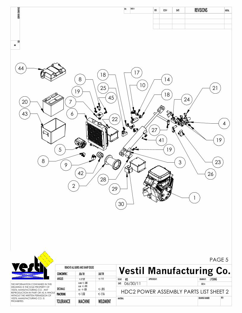
HDC2 POWER ASSEMBLY PARTS LIST SHEET 206/30/11
PAGE 6
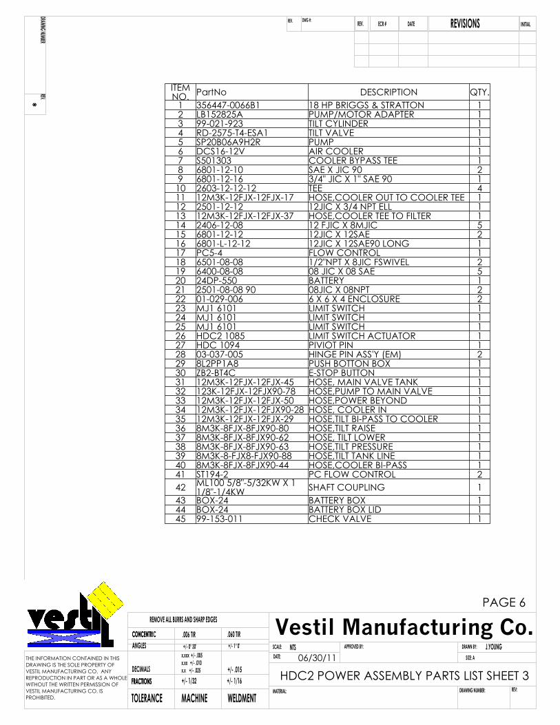
ITEM NO. PartNo DESCRIPTION QTY.
1 356447-0066B1 18 HP BRIGGS & STRATTON 12 LB152825A PUMP/MOTOR ADAPTER 13 99-021-923 TILT CYLINDER 14 RD-2575-T4-ESA1 TILT VALVE 15 SP20B06A9H2R PUMP 16 DCS16-12V AIR COOLER 17 S501303 COOLER BYPASS TEE 18 6801-12-10 SAE X JIC 90 29 6801-12-16 3/4" JIC X 1" SAE 90 110 2603-12-12-12 TEE 411 12M3K-12FJX-12FJX-17 HOSE,COOLER OUT TO COOLER TEE 112 2501-12-12 12JIC X 3/4 NPT ELL 113 12M3K-12FJX-12FJX-37 HOSE,COOLER TEE TO FILTER 114 2406-12-08 12 FJIC X 8MJIC 515 6801-12-12 12JIC X 12SAE 216 6801-L-12-12 12JIC X 12SAE90 LONG 117 PC5-4 FLOW CONTROL 118 6501-08-08 1/2"NPT X 8JIC FSWIVEL 219 6400-08-08 08 JIC X 08 SAE 520 24DP-550 BATTERY 121 2501-08-08 90 08JIC X 08NPT 222 01-029-006 6 X 6 X 4 ENCLOSURE 223 MJ1 6101 LIMIT SWITCH 124 MJ1 6101 LIMIT SWITCH 125 MJ1 6101 LIMIT SWITCH 126 HDC2 1085 LIMIT SWITCH ACTUATOR 127 HDC 1094 PIVIOT PIN 128 03-037-005 HINGE PIN ASS'Y (EM) 229 8L2PP1A8 PUSH BOTTON BOX 130 ZB2-BT4C E-STOP BUTTON 131 12M3K-12FJX-12FJX-45 HOSE, MAIN VALVE TANK 132 123K-12FJX-12FJX90-78 HOSE,PUMP TO MAIN VALVE 133 12M3K-12FJX-12FJX-50 HOSE,POWER BEYOND 134 12M3K-12FJX-12FJX90-28 HOSE, COOLER IN 135 12M3K-12FJX-12FJX-29 HOSE,TILT BI-PASS TO COOLER 136 8M3K-8FJX-8FJX90-80 HOSE,TILT RAISE 137 8M3K-8FJX-8FJX90-62 HOSE, TILT LOWER 138 8M3K-8FJX-8FJX90-63 HOSE,TILT PRESSURE 139 8M3K-8-FJX8-FJX90-88 HOSE,TILT TANK LINE 140 8M3K-8FJX-8FJX90-44 HOSE,COOLER BI-PASS 141 ST194-2 PC FLOW CONTROL 242 ML100 5/8"-5/32KW X 1
1/8"-1/4KW SHAFT COUPLING 143 BOX-24 BATTERY BOX 144 BOX-24 BATTERY BOX LID 145 99-153-011 CHECK VALVE 1
NTS J.YOUNGSCALE:DATE:
APPROVED BY: DRAWN BY:
DRAWING NUMBER:MATERIAL:TOLERANCE MACHINE WELDMENTFRACTIONSFRACTIONSDECIMALS
ANGLESCONCENTRICCONCENTR
+/- 1/32 +/- 1/16+/- .015
.006 TIR .060 TIR
REMOVE ALL BURRS AND SHARP EDGES
x.x +/- .025x.xx +/- .010x.xxx +/- .005
+/- 0° 30' +/- 1° 0'
REV:
SIZE: A
*DRAWING NUMBER
REV.
DATE INITIALREVISIONSREV.DWG #:REV. ECR #
THE INFORMATION CONTAINED IN THISDRAWING IS THE SOLE PROPERTY OFVESTIL MANUFACTURING CO. ANY REPRODUCTION IN PART OR AS A WHOLEWITHOUT THE WRITTEN PERMISSION OFVESTIL MANUFACTURING CO. IS PROHIBITED.
Vestil Manufacturing Co.
HDC2 POWER ASSEMBLY PARTS LIST SHEET 306/30/11
PAGE 7
26
4
3
5
1
8
9
7
2710
24
252 6
8
30
29
NTS J.YOUNGSCALE:DATE:
APPROVED BY: DRAWN BY:
DRAWING NUMBER:MATERIAL:TOLERANCE MACHINE WELDMENTFRACTIONSFRACTIONSDECIMALS
ANGLESCONCENTRICCONCENTR
+/- 1/32 +/- 1/16+/- .015
.006 TIR .060 TIR
REMOVE ALL BURRS AND SHARP EDGES
x.x +/- .025x.xx +/- .010x.xxx +/- .005
+/- 0° 30' +/- 1° 0'
REV:
SIZE: A
*DRAWING NUMBER
REV.
DATE INITIALREVISIONSREV.DWG #:REV. ECR #
THE INFORMATION CONTAINED IN THISDRAWING IS THE SOLE PROPERTY OFVESTIL MANUFACTURING CO. ANY REPRODUCTION IN PART OR AS A WHOLEWITHOUT THE WRITTEN PERMISSION OFVESTIL MANUFACTURING CO. IS PROHIBITED.
Vestil Manufacturing Co.
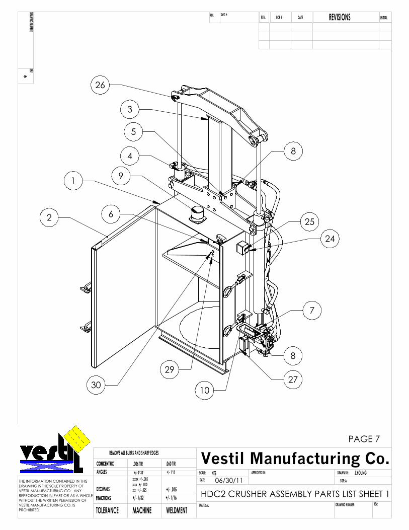
HDC2 CRUSHER ASSEMBLY PARTS LIST SHEET 106/30/11
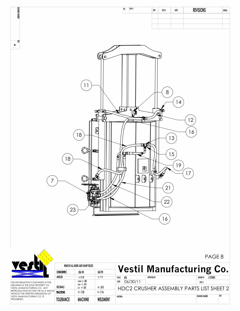
16
17
12
14
13
15
118
19
18
16
21
22
18
23
7
PAGE 8
NTS J.YOUNGSCALE:DATE:
APPROVED BY: DRAWN BY:
DRAWING NUMBER:MATERIAL:TOLERANCE MACHINE WELDMENTFRACTIONSFRACTIONSDECIMALS
ANGLESCONCENTRICCONCENTR
+/- 1/32 +/- 1/16+/- .015
.006 TIR .060 TIR
REMOVE ALL BURRS AND SHARP EDGES
x.x +/- .025x.xx +/- .010x.xxx +/- .005
+/- 0° 30' +/- 1° 0'
REV:
SIZE: A
*DRAWING NUMBER
REV.
DATE INITIALREVISIONSREV.DWG #:REV. ECR #
THE INFORMATION CONTAINED IN THISDRAWING IS THE SOLE PROPERTY OFVESTIL MANUFACTURING CO. ANY REPRODUCTION IN PART OR AS A WHOLEWITHOUT THE WRITTEN PERMISSION OFVESTIL MANUFACTURING CO. IS PROHIBITED.
Vestil Manufacturing Co.
HDC2 CRUSHER ASSEMBLY PARTS LIST SHEET 206/30/11
PAGE 9
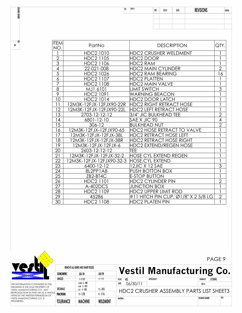
ITEM NO. PartNo DESCRIPTION QTY.
1 HDC2 1010 HDC2 CRUSHER WELDMENT 12 HDC2 1105 HDC2 DOOR 13 HDC2 1106 HDC2 RAM 14 22-021-008 HDC2 MAIN CYLINDER 25 HDC2 1026 HDC2 RAM BEARING 166 HDC2 1107 HDC2 PLATTEN 17 HDC2 1108 HDC2 MAIN VALVE 18 MJ1 6101 LIMIT SWITCH 39 HDC2 1091 WARNING BEACON 110 HDC2 1014 HDC2 DOOR LATCH 111 12M3K-12FJX-12FJX90-22R HDC2 RIGHT RETRACT HOSE 112 12M3K-12FJX-12FJX90-22L HDC2 LEFT RETRACT HOSE 113 2703-12-12-12 3/4" JIC BULKHEAD TEE 214 6801-12-10 SAE X JIC 90 415 306-12 BULKHEAD NUT 216 12M3K-12FJX-12FJX90-65 HDC2 HOSE RETRACT TO VALVE 117 12M3K-12FJX-12FJX-38L HDC2 RETRACT HOSE LEFT 118 12M3K-12FJX-12FJX-38R HDC2 RETRACT HOSE RIGHT 119 12M3K-12FJX-12FJX-6 HDC2 EXTEND/REGEN HOSE 120 2603-12-12-12 TEE 121 12M3K-12FJX-12FJX-32-2 HOSE CYL EXTEND REGEN 122 12M3K-12FJX-12FJX90-32-3 HOSE,CYL EXTEND 123 6400-12-12 12JIC X 12 SAE 324 8L2PP1A8 PUSH BOTTON BOX 125 ZB2-BT4C E-STOP BUTTON 126 HDC2 1101 HDC2 CYLINDER PIN 227 A-402DCS JUNCTION BOX 128 HDC2 1109 HDC2 UPPER LIMIT ROD 129 45286 #11 HITCH PIN CLIP, Ø1/8" X 2 5/8 LG 230 HDC2 1108 HDC2 PLATEN PIN 1
NTS J.YOUNGSCALE:DATE:
APPROVED BY: DRAWN BY:
DRAWING NUMBER:MATERIAL:TOLERANCE MACHINE WELDMENTFRACTIONSFRACTIONSDECIMALS
ANGLESCONCENTRICCONCENTR
+/- 1/32 +/- 1/16+/- .015
.006 TIR .060 TIR
REMOVE ALL BURRS AND SHARP EDGES
x.x +/- .025x.xx +/- .010x.xxx +/- .005
+/- 0° 30' +/- 1° 0'
REV:
SIZE: A
*DRAWING NUMBER
REV.
DATE INITIALREVISIONSREV.DWG #:REV. ECR #
THE INFORMATION CONTAINED IN THISDRAWING IS THE SOLE PROPERTY OFVESTIL MANUFACTURING CO. ANY REPRODUCTION IN PART OR AS A WHOLEWITHOUT THE WRITTEN PERMISSION OFVESTIL MANUFACTURING CO. IS PROHIBITED.
Vestil Manufacturing Co.
HDC2 CRUSHER ASSEMBLY PARTS LIST SHEET306/30/11
HDC-900-GPT Manual 08/2012
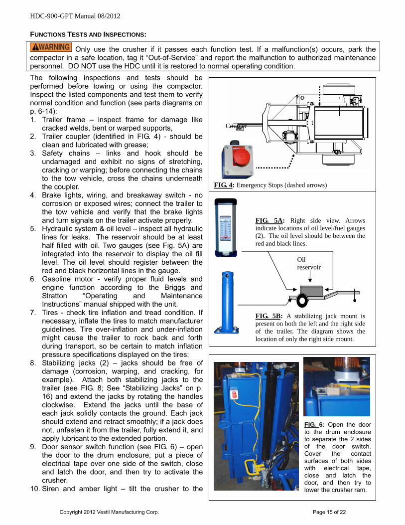
FUNCTIONS TESTS AND INSPECTIONS:
Only use the crusher if it passes each function test. If a malfunction(s) occurs, park the compactor in a safe location, tag it “Out-of-Service” and report the malfunction to authorized maintenance personnel. DO NOT use the HDC until it is restored to normal operating condition.
The following inspections and tests should be performed before towing or using the compactor. Inspect the listed components and test them to verify normal condition and function (see parts diagrams on p. 6-14): 1. Trailer frame – inspect frame for damage like
cracked welds, bent or warped supports, 2. Trailer coupler (identified in FIG. 4) - should be
clean and lubricated with grease; 3. Safety chains – links and hook should be
undamaged and exhibit no signs of stretching, cracking or warping; before connecting the chains to the tow vehicle, cross the chains underneath the coupler.
4. Brake lights, wiring, and breakaway switch - no corrosion or exposed wires; connect the trailer to the tow vehicle and verify that the brake lights and turn signals on the trailer activate properly.
5. Hydraulic system & oil level – inspect all hydraulic lines for leaks. The reservoir should be at least half filled with oil. Two gauges (see Fig. 5A) are integrated into the reservoir to display the oil fill level. The oil level should register between the red and black horizontal lines in the gauge.
6. Gasoline motor - verify proper fluid levels and engine function according to the Briggs and Stratton “Operating and Maintenance Instructions” manual shipped with the unit.
FIG. 4: Emergency Stops (dashed arrows)
Coupler
FIG. 5B: A stabilizing jack mount is present on both the left and the right side of the trailer. The diagram shows the location of only the right side mount.
Oil reservoir
FIG. 5A: Right side view. Arrows indicate locations of oil level/fuel gauges (2). The oil level should be between the red and black lines.
7. Tires - check tire inflation and tread condition. If necessary, inflate the tires to match manufacturer guidelines. Tire over-inflation and under-inflation might cause the trailer to rock back and forth during transport, so be certain to match inflation pressure specifications displayed on the tires;
FIG. 6: Open the door to the drum enclosure to separate the 2 sides of the door switch. Cover the contact surfaces of both sides with electrical tape, close and latch the door, and then try to lower the crusher ram.
8. Stabilizing jacks (2) – jacks should be free of damage (corrosion, warping, and cracking, for example). Attach both stabilizing jacks to the trailer (see FIG. 8; See “Stabilizing Jacks” on p. 16) and extend the jacks by rotating the handles clockwise. Extend the jacks until the base of each jack solidly contacts the ground. Each jack should extend and retract smoothly; if a jack does not, unfasten it from the trailer, fully extend it, and apply lubricant to the extended portion.
9. Door sensor switch function (see FIG. 6) – open the door to the drum enclosure, put a piece of electrical tape over one side of the switch, close and latch the door, and then try to activate the crusher.
10. Siren and amber light – tilt the crusher to the
Copyright 2012 Vestil Manufacturing Corp. Page 15 of 22
HDC-900-GPT Manual 08/2012
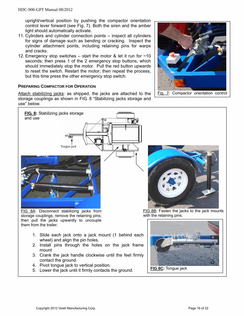
upright/vertical position by pushing the compactor orientation control lever forward (see Fig. 7). Both the siren and the amber light should automatically activate.
Fig. 7: Compactor orientation control
11. Cylinders and cylinder connection points – inspect all cylinders for signs of damage such as bending or cracking. Inspect the cylinder attachment points, including retaining pins for warps and cracks.
12. Emergency stop switches – start the motor & let it run for ~10 seconds; then press 1 of the 2 emergency stop buttons, which should immediately stop the motor. Pull the red button upwards to reset the switch. Restart the motor; then repeat the process, but this time press the other emergency stop switch.
PREPARING COMPACTOR FOR OPERATION
Attach stabilizing jacks: as shipped, the jacks are attached to the storage couplings as shown in FIG. 8 “Stabilizing jacks storage and use” below.
1. Slide each jack onto a jack mount (1 behind each
wheel) and align the pin holes. 2. Install pins through the holes on the jack frame
mount 3. Crank the jack handle clockwise until the feet firmly
contact the ground. 4. Pivot tongue jack to vertical position. 5. Lower the jack until it firmly contacts the ground.
FIG 8C: Tongue jack
FIG. 4 “Bird’s eye view diagram
Tongue jack
FIG. 8: Stabilizing jacks storage and use
FIG 8B: Fasten the jacks to the jack mounts with the retaining pins.
FIG 8A: Disconnect stabilizing jacks from storage couplings; remove the retaining pins; then pull the jacks upwardly to uncouple them from the trailer.
Copyright 2012 Vestil Manufacturing Corp. Page 16 of 22
HDC-900-GPT Manual 08/2012
Copyright 2012 Vestil Manufacturing Corp. Page 17 of 22
OPERATION
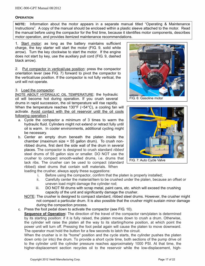
NOTE: Information about the motor appears in a separate manual titled “Operating & Maintenance Instructions”. A copy of the manual should be enclosed within a plastic sleeve attached to the motor. Read the manual before using the compactor for the first time, because it identifies motor components, describes motor operation, and provides itemized maintenance recommendations.
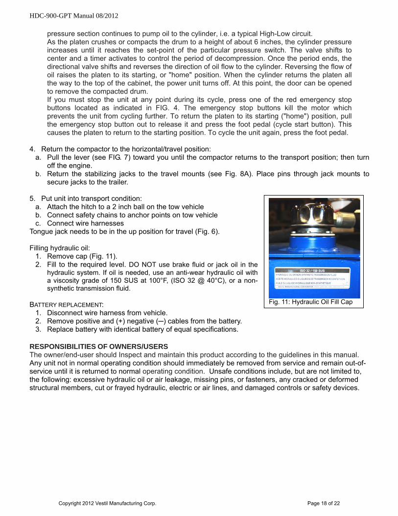
1. Start motor: as long as the battery maintains sufficient charge, the key starter will start the motor (FIG. 9, solid white arrow). Turn the key clockwise to start the motor. If the engine does not start by key, use the auxiliary pull cord (FIG. 9, dashed black arrow). 2. Put compactor in vertical/use position: press the compactor orientation lever (see FIG. 7) forward to pivot the compactor to the vertical/use position. If the compactor is not fully vertical, the unit will not operate. 3. Load the compactor: [NOTE ABOUT HYDRAULIC OIL TEMPERATURE: the hydraulic oil will become hot during operation. If you crush several drums in rapid succession, the oil temperature will rise rapidly. When the temperature reaches 130°F (~54°C), a cooling fan will activate. Avoid contact with the oil reservoir until the oil cools following operation.]
FIG. 6: Gasoline motor
a. Cycle the compactor a minimum of 3 times to warm the hydraulic fluid. Cylinders might not extend or retract fully until oil is warm. In cooler environments, additional cycling might be necessary.
b. Center an empty drum beneath the platen inside the chamber (maximum size = 55 gallon drum). To crush non-ribbed drums, first dent the side wall of the drum in several places. The compactor is designed to crush standard ribbed steel drums of 55 gallon size or smaller. DO NOT use the crusher to compact smooth-walled drums, i.e. drums that lack ribs. The crusher can be used to compact (standard ribbed) steel drums that contain soft materials. When loading the crusher, always apply these suggestions:
FIG. 7: Auto Cycle Valve
i. Before using the compactor, confirm that the platen is properly installed; ii. Carefully center the material/item to be crushed under the platen, because an offset or
uneven load might damage the cylinder rod; iii. DO NOT fill drums with scrap metal, paint cans, etc. which will exceed the crushing
capacity of the unit and significantly damage the crusher. NOTE: The crusher is designed to compact standard, ribbed steel drums. However, the crusher might
not compact a particular drum. It is also possible that the crusher might sustain minor damage during the compaction process.
c. Press the foot pedal down to activate the compactor (see FIG. 10). Sequence of Operation: The direction of the travel of the compactor ram/platen is determined by its starting position: if it is fully raised, the platen moves down to crush a drum. Otherwise, the cylinder will raise the platen all the way to its starting/home position, at which point the power unit will turn off. Pressing the foot pedal again will cause the platen to move downward. The operator must hold the button for a few seconds to latch the circuit. When the crusher is in its "home" position and the cycle starts, the cylinder pushes the platen down onto (or into) the drum. To provide a short cycle time, both sections of the pump drive oil to the cylinder until the cylinder pressure reaches approximately 1000 PSI. At that time, the higher-displacement section recycles oil to the reservoir while the low-displacement, high-
HDC-900-GPT Manual 08/2012
pressure section continues to pump oil to the cylinder, i.e. a typical High-Low circuit. As the platen crushes or compacts the drum to a height of about 6 inches, the cylinder pressure increases until it reaches the set-point of the particular pressure switch. The valve shifts to center and a timer activates to control the period of decompression. Once the period ends, the directional valve shifts and reverses the direction of oil flow to the cylinder. Reversing the flow of oil raises the platen to its starting, or "home" position. When the cylinder returns the platen all the way to the top of the cabinet, the power unit turns off. At this point, the door can be opened to remove the compacted drum. If you must stop the unit at any point during its cycle, press one of the red emergency stop buttons located as indicated in FIG. 4. The emergency stop buttons kill the motor which prevents the unit from cycling further. To return the platen to its starting ("home") position, pull the emergency stop button out to release it and press the foot pedal (cycle start button). This causes the platen to return to the starting position. To cycle the unit again, press the foot pedal.
4. Return the compactor to the horizontal/travel position:
a. Pull the lever (see FIG. 7) toward you until the compactor returns to the transport position; then turn off the engine.
b. Return the stabilizing jacks to the travel mounts (see Fig. 8A). Place pins through jack mounts to secure jacks to the trailer.
5. Put unit into transport condition:
Fig. 11: Hydraulic Oil Fill Cap
a. Attach the hitch to a 2 inch ball on the tow vehicle b. Connect safety chains to anchor points on tow vehicle c. Connect wire harnesses
Tongue jack needs to be in the up position for travel (Fig. 6). Filling hydraulic oil:
1. Remove cap (Fig. 11). 2. Fill to the required level. DO NOT use brake fluid or jack oil in the
hydraulic system. If oil is needed, use an anti-wear hydraulic oil with a viscosity grade of 150 SUS at 100°F, (ISO 32 @ 40°C), or a non-synthetic transmission fluid.
BATTERY REPLACEMENT:
1. Disconnect wire harness from vehicle. 2. Remove positive and (+) negative (─) cables from the battery. 3. Replace battery with identical battery of equal specifications.
RESPONSIBILITIES OF OWNERS/USERS The owner/end-user should Inspect and maintain this product according to the guidelines in this manual. Any unit not in normal operating condition should immediately be removed from service and remain out-of-service until it is returned to normal operating condition. Unsafe conditions include, but are not limited to, the following: excessive hydraulic oil or air leakage, missing pins, or fasteners, any cracked or deformed structural members, cut or frayed hydraulic, electric or air lines, and damaged controls or safety devices.
Copyright 2012 Vestil Manufacturing Corp. Page 18 of 22
HDC-900-GPT Manual 08/2012
INSPECTIONS & MAINTENANCE INSTRUCTIONS [EMPTY THE CRUSHER BEFORE INSPECTING OR PERFORMING MAINTENANCE ON IT.]
(A) Before each use, inspect the crusher and remove it from service if any of the following issues are observed:
1.) Frayed wires; 2.) Oil leaks; 3.) Pinched or chafed hoses, loose fittings; 4.) Structural deformation of frame; 5.) Unusual noise or binding
(B) Monthly Inspections:
1.) Check oil level. Oil should be 2" to 2½" below the top of the tank with the cylinder in the fully retracted position. Add as necessary.
2.) Check for oil leaks. 3.) Check for worn or damaged hydraulic hoses, electrical wires, and cords. Repair as
necessary. 4.) Cycle the crusher and listen for unusual noise. 5.) Make sure all warning labels are readable and in place according to the diagram on p. 20. 6.) Remove dirt and debris.
(C) Yearly Inspection:
Change the hydraulic oil at least once per year. However, because the oil should be changed as soon as it darkens, looks milky, or becomes gritty, oil changes might be required more frequently than every 12 months.
After draining the oil from the reservoir, flush the reservoir before refilling it. If the oil looks milky, water is present and the oil should be changed immediately. Recommended hydraulic oil: Purity ISO AW-32 Hydraulic fluid or equal.
(D) Changing tires: (compactor must be in the horizontal/transport position) 1. Attach both stabilizing jacks to the jack mounts. 2. Raise the rear of the unit up so the tire is off the ground. 3. Remove lug nuts. 4. Replace Tire. 5. Re-install tire with lug nuts. 6. Torque to required specifications.
(E) Filling hydraulic oil:
1. Remove cap (Fig. 11). 2. Fill to the required level. DO NOT use brake fluid or jack oil in the hydraulic system. If oil is needed,
use an anti-wear hydraulic oil with a viscosity grade of 150 SUS at 100°F, (ISO 32 @ 40°C), or a non-synthetic transmission fluid.
(F) Battery replacement:
1. Disconnect wire harness from vehicle. 2. Remove positive and (+) negative (─) cables from the battery. 3. Replace battery with identical battery of equal specifications.
Copyright 2012 Vestil Manufacturing Corp. Page 19 of 22
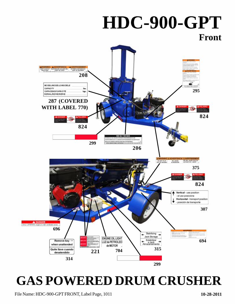
HDC-900-GPT
GAS POWERED DRUM CRUSHER
Front
295
696
694
307
314
375
221 315704
206
10-28-2011File Name: HDC-900-GPT FRONT, Label Page, 1011
287 (COVEREDWITH LABEL 770)
208
299
299
824
824
824
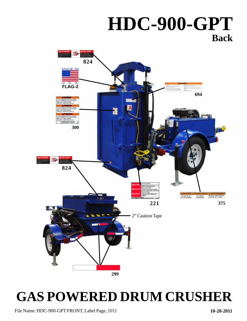
HDC-900-GPT
300
Back
824
824
694
221 375
GAS POWERED DRUM CRUSHER10-28-2011File Name: HDC-900-GPT FRONT, Label Page, 1011
2” Caution Tape
299
Rev. 01/2011
LIMITED WARRANTY
Vestil Manufacturing Corporation (“Vestil”) warrants this HDC-900 (excluding “Washdown” model HDC-900-WD, which is covered by a separate warranty) to be free of defects in material and workmanship during the warranty period. Our warranty obligation is to provide a replacement for a defective original part if the part is covered by the warranty, after we receive a proper request from the warrantee (you) for warranty service.
Who may request service? Only a warrantee may request service. You are a warrantee if you purchased the product from Vestil or from an authorized distributor AND Vestil has been fully paid.
What is an “original part”? An original part is a part used to make the product as shipped to the warrantee.
What is a “proper request”? A request for warranty service is proper if Vestil receives: 1) a photocopy of the Customer Invoice that displays the shipping date; AND 2) a written request for warranty service including your name and phone number. Send requests by any of the following methods:
Mail Fax Email Vestil Manufacturing Corporation (260) 665-1339 [email protected] 2999 North Wayne Street, PO Box 507 Phone Angola, IN 46703 (260) 665-7586
In the written request, list the parts believed to be defective and include the address where replacements should be delivered.
What is covered under the warranty? After Vestil receives your request for warranty service, an authorized representative will contact you to determine whether your claim is covered by the warranty. Before providing warranty service, Vestil may require you to send the entire product, or just the defective part or parts, to its facility in Angola, IN. The warranty covers defects in the following original dynamic components: motors, hydraulic pumps, electronic controllers, switches and cylinders. It also covers defects in original parts that wear under normal usage conditions (“wearing parts”): bearings, hoses, wheels, seals, brushes, batteries, and the battery charger.
How long is the warranty period? The warranty period for original components is 1 year. The warranty period begins on the date when Vestil ships the product to the warrantee. If the product was purchased from an authorized distributor, the period begins when the distributor ships the product. Vestil may extend the warranty period for products shipped from authorized distributors by up to 30 days to account for shipping time.
If a defective part is covered by the warranty, what will Vestil do to correct the problem? Vestil will provide an appropriate replacement for any covered part. An authorized representative of Vestil will contact you to discuss your claim.
What is not covered by the warranty? 1. Labor; 2. Freight; 3. Occurrence of any of the following, which automatically voids the warranty:
Product misuse; Negligent operation or repair; Corrosion or use in corrosive conditions; Inadequate or improper maintenance; Damage sustained during shipping; Accidents involving the product; Unauthorized modifications: DO NOT modify the product IN ANY WAY without first receiving
written authorization from Vestil. Modification(s) might make the product unsafe to use or might cause excessive and/or abnormal wear.
Do any other warranties apply to the product? Vestil Manufacturing Corp. makes no other express warranties. All implied warranties are disclaimed to the extent allowed by law. Any implied warranty not disclaimed is limited in scope to the terms of this Limited Warranty.
Page 13A