Embed Size (px)
Citation preview
Headbox Slice Opening Arrangement
A developed version and a new one
Läppöppningsarrangemang för inloppslådor
En utvecklad och en ny version
Viktor Bergström
Faculty of Health, Science and Technology
Department of Engineering and Physics, Mechanical and Materials Engineering
30hp
Supervisors: Fredrik Thuvander KAU, Andreas Nordin and Anki Rådman Valmet AB
Examiner: Jens Bergström
2014-09-09
ii
Acknowledgements
I would like to send a special thanks to my supervisors Anki Rådman and Andreas Nordin at
Valmet AB for reflections on the final result and for their helpful advices and support. I would
also like to thank the whole design team of the headbox for their helpful guidance and for
making me feel welcome and appreciated. The thanks are also extended to Jan Paulsson and
Jonas Cederlöf for their helpful supervision during the Finite element analysis.
Peter Andersson at UW-elast also deserves an acknowledgement for the manufacturing of the
polyurethane sheet and the helpful advices about elastomers.
I would also like to send a special thanks to my supervisor Fredrik Thuvander at Karlstad
University for guiding me through the process and giving me an extensive support. The
discussion and contribution to the final result has truly been a delightful experience.
iii
Sammanfattning
Syftet med inloppslådan är att den ska transformera ett flöde av fibersuspension till en stråle
som är mellan 4 och 20 mm tjock och 3-8 m bred, beroende på pappersmaskinsmodell. För att
justera strålens tjocklek används läppjusteringsanordningen.
Målet med detta arbete var att utveckla inloppslådan och dess läppöppningsarrangemang så
att den kan användas till en pappersmaskin som är breddare än 6 meter. Projektet inleddes
med att skapa en förståelse för problemet samt att undersöka vilka produkt- och kundkrav det
finns på inloppslådan. För att utnyttja hela iderymden användes ett antal
idegenereringsmetoder. Utvärdering av koncepten genomfördes med hjälp av en metod som
heter Analytic hierarchy process (AHP) som är en metod som används för att tydliggöra
beslutsvägen.
Utifrån utvärdering med AHP valdes två koncept ut. En modifierad lösning av det nuvarande
läppöppningsarrangemangen och ett nytt koncept vilket justerar läppöppningen med hjälp av
ett antal trycksatta fickor och en vinge. För att ytterligare utveckla den modifierade
inloppslådan användes Finita Elementmetoden. Under simuleringen jämfördes elastisk
deformation i den nuvarande och den modifierade lösningen. Det nya konceptet utvecklades
genom att den nya konstruktionen beskrevs utifrån struktur, materialval och
tillverkningsmetoder.
Sammantaget kan det sägas att den modifierade inloppslådan löser problemställning och
bibehåller den nuvarande kvalitén på pappret. Den innovativa och nya lösningen möjliggör en
mer exakt justering av läppöppningen och ökar möjligheten att modularisera inloppslådan.
iv
Executive summary
The purpose of the headbox is to convert a flow of fiber suspension to a jet, with a thickness
between 4 and 20mm and a width between 3 -8meters, depending on the paper machine
model. To adjust the beam thickness, the lip adjustment arrangement is used.
This master thesis was written to develop the headbox and the lip adjustment system, for paper
machines with a width over 6 meters. In the beginning of the project much focus was layed on
understanding the problem and develop the product and customer requirements of the
Headbox.
In order to utilize the entire idea space a number of idea generation methods were used. The
evaluation of concepts were conducted with the method Analytic hierarchy process (AHP),
which is a method for clarifying the decision pattern.
From the evaluation of the concept, two concepts were chosen. A modification of the existing
headbox and a new concept, which adjusts the slice opening with a number of elastic pockets
and a wedge. To further evaluate the modified headbox concepts the Finite Element Method
was used. During the simulations the elastic deformation was compared between the current
and the modified solution. The second concept was developed by describing the new design
and motivated the chosen material and structures.
Overall it can be said that the modification of the current headbox solves the main problem
and maintains the current quality on the paper. The new and innovative solution enables a
more exact adjustment of the lip opening and allows a larger potential of modularization.
v
Definition
In this thesis the tissue machine was defined with three directions, machine direction (MD),
cross direction (CD) and thickness (ZD). The flow from the Headbox is directed in positive
machine direction and the cross direction is in the perpendicular plane against MD.
The following parameters is important in the final tissue paper
Base weight: The weight of the tissue paper in the cross direction.
Formation: The amount of very fine scale fiber floc in a paper sheet is called
formation. If the paper contains many flocs, the formation of the paper is bad. A good
formation is when the paper contains no visible fiber flocs.
vi
Table of Contents 1. Introduction ............................................................................................................................ 1
1.1 Background ...................................................................................................................... 1
1.2 Purpose ............................................................................................................................. 2
1.3 Definition of problem ....................................................................................................... 2
1.4 Delimitations .................................................................................................................... 2
2. Analysis of current headbox ................................................................................................... 3
2.1 Process description of headbox ........................................................................................ 3
2.2 Principle of the headbox ................................................................................................... 4
2.3 Material in headbox .......................................................................................................... 4
2.4 Description of apron Beam............................................................................................... 5
2.5 Benchmarking .................................................................................................................. 5
2.6 Scientific investigation of Headboxes .............................................................................. 6
2.7 Observations from current construction ........................................................................... 7
3. Method ................................................................................................................................... 8
3.1 Understanding the problem .............................................................................................. 8
3.2 Identify customer requirements and product requirements .............................................. 9
3.3 Concept generation ......................................................................................................... 10
3.4 Concept selection ........................................................................................................... 11
3.5 3D-design ....................................................................................................................... 12
3.6 Finite element analysis ................................................................................................... 13
3.6.1 Mesh ........................................................................................................................ 13
3.6.2 Simulation of apron beam ....................................................................................... 14
3.6.3 Simulation of slice wedge ....................................................................................... 16
3.7 Material selection ........................................................................................................... 16
3.8 Expansion test ................................................................................................................ 17
4. Results .................................................................................................................................. 18
4.1 Identify customer requirements and product requirements ............................................ 18
4.2 Generated concepts......................................................................................................... 20
4.3 Concept selection ........................................................................................................... 24
5. Design of modified apron beam ........................................................................................... 29
5.1 Simulation of apron beam .............................................................................................. 29
5.2 Cost comparison ............................................................................................................. 33
vii
6. Design of Pressurized pocket ............................................................................................... 34
6.1 Description of components in Pressurized pocket ......................................................... 34
6.2 Design of components in Pressurized pocket ................................................................. 35
6.3 Material selection ........................................................................................................... 38
6.4 3D-Layout of the concept Pressurized pocket ................................................................ 45
6.5 Modularization ............................................................................................................... 46
6.6 New wire attachment ...................................................................................................... 47
6.7 Pressure medium ............................................................................................................ 48
6.8 Design of the hydraulic system ...................................................................................... 50
6.9 Economical comparison ................................................................................................. 50
6.10 Expansion test .............................................................................................................. 51
7. Discussion ............................................................................................................................ 53
7.1 Important characteristics of headboxes .......................................................................... 53
7.2 The way to the concepts ................................................................................................. 53
7.3 Discussion of simulation of apron beam ........................................................................ 54
7.4 Discussion of pressurized pocket ................................................................................... 54
7.5 Discussion of economical justifiability .......................................................................... 56
7.6 Environmental effect ...................................................................................................... 56
7.7 Future work and suggestions for future research ........................................................... 57
8. Concluding remarks ............................................................................................................. 57
9. References ............................................................................................................................ 58
Appendix 1 Elastic deflection in chest roll ................................................................................. I
Appendix 2 Valmet AB and description of a Tissue machine ...................................................II
Appendix 3 Mechanical analysis of headbox ........................................................................... III
Appendix 4 Description of sub-criteria’s in Analytic hierarchy process ................................. VI
1
1. Introduction
1.1 Background In papermaking a water fiber suspension is formed and dried into a continuous paper web, for
a more detailed description see appendix 1. The formation of this web starts in the forming
section where the water fibre suspension is accelerated by passing through a contracting
nozzle that evenly spread out the jet on to a moving fabric or into the gap between two
moving fabrics. In the papermachine this nozzle contains a number of components and is
called headbox. The amount of fibers water suspension that is applied on the wire is
controlled by the slice opening arrangement. It consists of two lips that are parallel to each
other, depending on the distance between the lips different amount of water fiber suspension
is exiting the headbox. There is two ways to increase the production volume in a paper
machine, increasing the machine width or production speed. This thesis is about how the
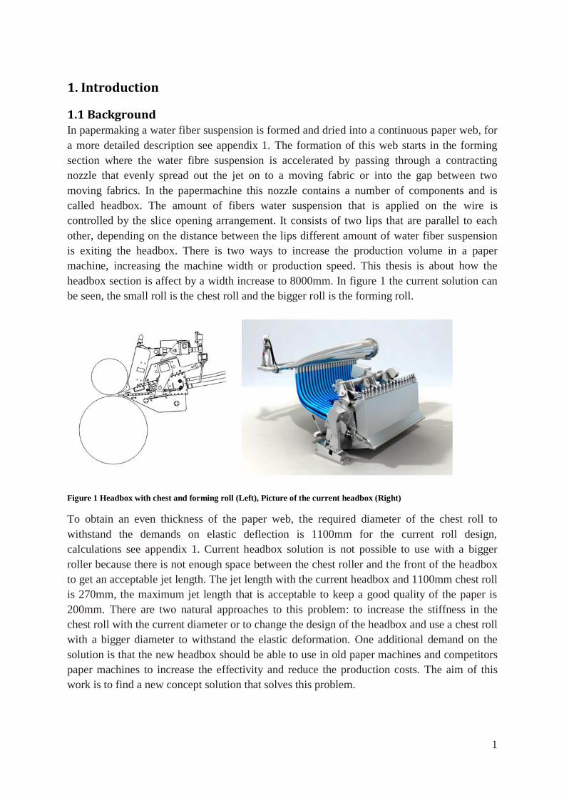
headbox section is affect by a width increase to 8000mm. In figure 1 the current solution can
be seen, the small roll is the chest roll and the bigger roll is the forming roll.
Figure 1 Headbox with chest and forming roll (Left), Picture of the current headbox (Right)
To obtain an even thickness of the paper web, the required diameter of the chest roll to
withstand the demands on elastic deflection is 1100mm for the current roll design,
calculations see appendix 1. Current headbox solution is not possible to use with a bigger
roller because there is not enough space between the chest roller and the front of the headbox
to get an acceptable jet length. The jet length with the current headbox and 1100mm chest roll
is 270mm, the maximum jet length that is acceptable to keep a good quality of the paper is
200mm. There are two natural approaches to this problem: to increase the stiffness in the
chest roll with the current diameter or to change the design of the headbox and use a chest roll
with a bigger diameter to withstand the elastic deformation. One additional demand on the
solution is that the new headbox should be able to use in old paper machines and competitors
paper machines to increase the effectivity and reduce the production costs. The aim of this
work is to find a new concept solution that solves this problem.
2
1.2 Purpose The purpose of this work is to use a scientific and structural way to analyze the current
solution and with the product development process, develop a new design for the gap
adjustment, in the 8000mm wide headboxes. The new solution should allow the use of a chest
roll with diameter of up to 1100mm, without getting a jet length over 200mm and maintain or
increase the final quality of the paper.
1.3 Definition of problem There are a number of possible approaches to this problem, but the focuses in this thesis has
been to understand the purpose of the different components in the headbox, and to analyze the
current design and understand the internal and external forces and torques. From this analysis
determine the customer and product requirement, and generate a number of concepts that
allows the use of a 1100mm chest roll without increasing the jet length over 200mm. The
concepts are then evaluated against product requirements. These chosen concepts are the
further developed and presented with a 3D model and an economical comparison. To verify
that this new solutions is applicable, both from a mechanical and an economic point of view,
the new solutions are compared with the current design.
1.4 Delimitations The focus in this study is the slice opening arrangement in the Headbox.
The presented material will not contain any final drawing only conceptual 3D models
This thesis involves basic information about the simulation but does not go into detail concerning the theory behind FEA.
The focus in this thesis is to motivate the chosen material from a scientific approach
and not in detail descript deformation and fracture properties of every material that is
mentioned.
The aim with the design of the hydraulic system is to understand what type of
components that is necessary to be able to create an economical comparison and
evaluate if the new solution is economically justifiable.
3
2. Analysis of current headbox
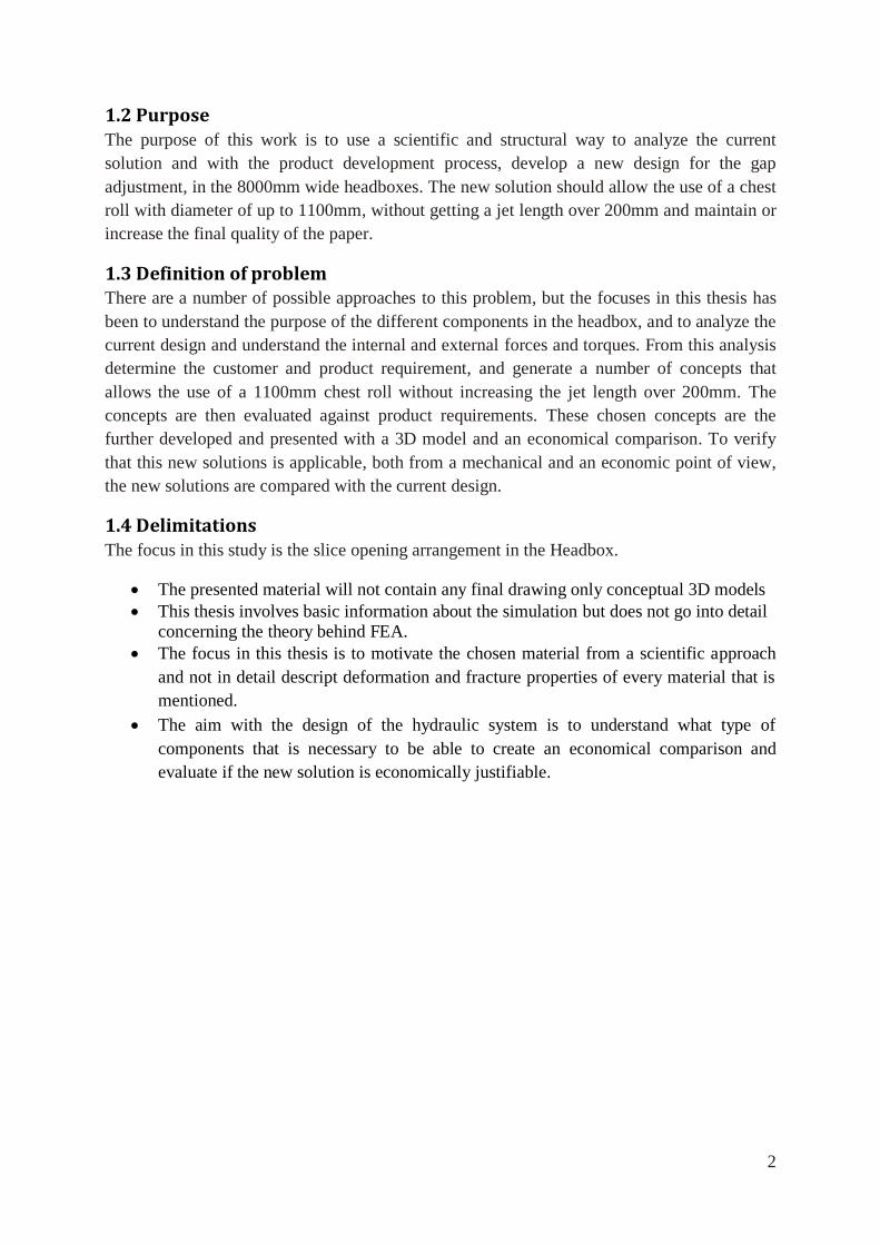
2.1 Process description of headbox The headbox consist of a number of components support beam, tube bank, roof , slice opening
arrangement and apron beam. To understand the purpose of the headbox a section of the
process flow around the headbox in the paper machine is used, see figure 2. The process starts
when the water fiber suspension is pumped into the tapered headers. In the headers the
pressure is balanced and distributed through a number of rubber hoses into the tube bank. In
the beginning of the tube bank the pressure is equalized in the cross direction. Then it enters
the turbulence generator which is a part of the tube bank, in this part the flow is accelerated to
achieve a pressure drop and higher turbulence. Then it enters the converging nozzle where the
flow is accelerated to desired jet speed. Inside the converging nozzle a number of wedges are
placed to maintain the sufficient turbulence level. After the converging nozzle the jet is
exiting the headbox and enters the nip of the forming roll and chest roll. (Valmet 2014)
Figure 2 Process flow around the headbox
The purpose of the headbox:
Distribute the flow equally in the cross direction
Create accurate fiber concentration at different speed
Generate a satisfying formation
4
2.2 Principle of the headbox The water fiber suspension flows in the headbox from the headers to the nozzle. From the
nozzle a jet with uniformed cross machine velocity is delivered, with a thickness between 4-
20mm and a width between 3-8meters depending on headbox model. To achieve a good
formation and even water fiber suspension distribution in the paper, the turbulence levels in
the headbox needs to be sufficient. The turbulence generator inside the headbox is designed to
give a good fiber distribution and sufficient turbulence intensity. After the turbulence
generator, the flow enters the nozzle which is designed to give a short free jet length. To
adjust the paper sheet properties the geometry of the jet can be adjusted with a number of
process parameters. The quality of the paper sheet is depending on both the headbox and the
former roll. When the jet has left the headbox, the former roll only preserves the formation
that the headbox has generated therefore the jet geometry is important for the paper sheet
quality. To achieve the best mechanical properties and formation of the paper, a short free jet
length and optimized jet geometry are essential. Depending on the type of tissue paper which
will be produced, the setting is optimized regarding to the jet geometry. To validate the
adjustments, a measurement of base weight and the formation is conducted on dry paper with
a scanner about 2 seconds after it has exited the headbox. One important factor to be able to
produce a paper with high quality is to minimize the build-up of fibers and chemicals inside
the headbox. This means that the hydrodynamic design in the headbox is important to avoid
sticking of deposits to increase the quality of the paper. (Valmet, 2014)
2.2.1 Process parameters
The mechanical adjustment system in the headbox makes it possible to adjust the jet relative
to the fabric, chest- and forming-roll. The following parameters are possible to adjust
Jet impingement: The percentage of the jet which strikes the forming roll.
Jet angle: The angle between the fabric and jet
Jet length: The distance between the headbox lip tip and the hit point of forming roll
or fabric
Nip distance: The span between the chest roll and forming roll
2.3 Material in headbox The steel material in the headbox is a duplex stainless steel that consists of a ferritic and
austenitic zone that has high strength, good toughness and good corrosion resistance. The
duplex stainless steel that is used is LDX 2101. (Outokumpu, 2014a)
5
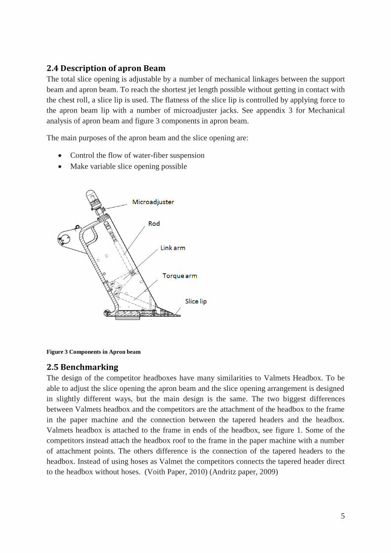
2.4 Description of apron Beam The total slice opening is adjustable by a number of mechanical linkages between the support
beam and apron beam. To reach the shortest jet length possible without getting in contact with
the chest roll, a slice lip is used. The flatness of the slice lip is controlled by applying force to
the apron beam lip with a number of microadjuster jacks. See appendix 3 for Mechanical
analysis of apron beam and figure 3 components in apron beam.
The main purposes of the apron beam and the slice opening are:
Control the flow of water-fiber suspension
Make variable slice opening possible
Figure 3 Components in Apron beam
2.5 Benchmarking The design of the competitor headboxes have many similarities to Valmets Headbox. To be
able to adjust the slice opening the apron beam and the slice opening arrangement is designed
in slightly different ways, but the main design is the same. The two biggest differences
between Valmets headbox and the competitors are the attachment of the headbox to the frame
in the paper machine and the connection between the tapered headers and the headbox.
Valmets headbox is attached to the frame in ends of the headbox, see figure 1. Some of the
competitors instead attach the headbox roof to the frame in the paper machine with a number
of attachment points. The others difference is the connection of the tapered headers to the
headbox. Instead of using hoses as Valmet the competitors connects the tapered header direct
to the headbox without hoses. (Voith Paper, 2010) (Andritz paper, 2009)
6
2.6 Scientific investigation of Headboxes The theories that the Headbox is based on is the knowledge about free liquid jets, for example
when you turn the water-tap on, you are using a circular free liquid jet. In the late 90s much
research around Headboxes was focused on fiber suspensions flow in the Tubebank and
turbulence generators.(Nordstrom 2003) During the latest century more research has been
focused on contraction ratio and the wedges effect on the final paper properties. The latest
year the development of computer power has led to an increase of studies that examine the
relation between experimental studies of headboxes with theoretical models.
Experimental study of headboxes has been done by a number of researchers, Nordström
(2003a) showed that the velocity difference between the wire and jet, have effect on the fiber
orientation. If the wire velocity is higher, than the velocity of the jet, the paper gets more
anisotropic in the machine direction. Zang (2001) also showed that an increasing in
contraction ratio in the planar contraction or nozzle creates a more anisotropic paper in the
machine direction. Ullman (1998) showed that when the flow is increased in a headbox with
contraction ratio from 25-50 the anisotropy in the final paper increase. But Nordström (2003a)
showed that the flow rate through a headbox with a contraction ratio of 7, 5 had a small effect.
On the final fiber orientation, in the paper sheet. The explanation by Nordström (2003a) is
that a higher contraction ratio in the nozzle gives a greater influence of the orientating in the
final paper, than the turbulence level in the nozzle. Olson (2002) also concluded that the fiber
orientation is independent of the flow rate and the only design parameter in the Headbox that
affects the fiber orientation is the contraction ratio. Nordström (2003b) also showed that the
anisotropi in the paper sheet was not uniformed over the thickness (Z), it was more anisotropy
in the core, than on the surfaces of the paper sheet. Many of the theoretical models that have
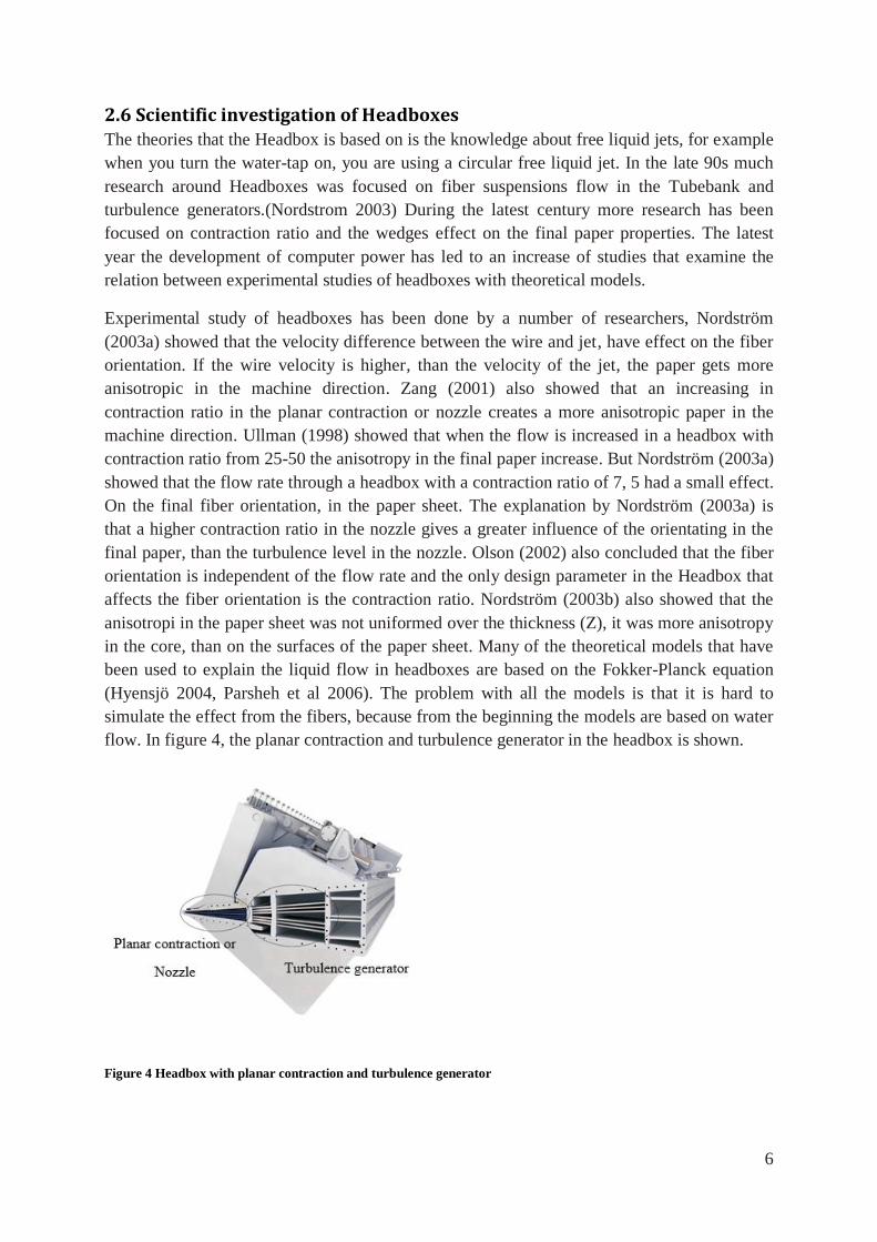
been used to explain the liquid flow in headboxes are based on the Fokker-Planck equation
(Hyensjö 2004, Parsheh et al 2006). The problem with all the models is that it is hard to
simulate the effect from the fibers, because from the beginning the models are based on water
flow. In figure 4, the planar contraction and turbulence generator in the headbox is shown.
Figure 4 Headbox with planar contraction and turbulence generator
7
One big problem with earlier headboxes was the large scale motions in the nozzle. This
problem was solved by inserting wedges in the nozzle that reduced the large scale motions.
The unwanted result from the large scale motions is a bad formation in the final paper. The
problem with a uniform paper in the thickness (Z) was also reduced by the wedges. (Carlsson
et al. 2009) Aidun and Kovacs (1995) suggested that the anisotropy in the cross direction is
due to the secondary flows generated in the boundary layer of the nozzle. A number of articles
have been written the recent years about how walls influence the fiber orientation and
formation because the thickness on the boundary layers is about 0.001m and the jet that leaves
the nozzle is about 0,01m. This means a large fraction is affected (Carlson et al. 2009). They
also showed that the walls influence on the fiber orientation in the middle of the paper is
small. Close to the walls the fibers are aligned more perpendicular to the walls. When the
water suspension flows further away from the wall, the fibers are aligned more in the machine
direction. The reason for this was found to be settling against the wall and contact between the
fiber ends and walls. (Holm and Söderberg 2007) (Carlson, et al 2009).
2.7 Observations from current construction
2.7.1 Dilution vs profiling system
Customers that choose a headbox with dilution system have two systems that adjust the base
weight of the final paper: Dilution system and profiling system. The explanation to this is the
proportions of the headboxes that are sold with dilution are small compared to total amount.
The customers who have chosen to buy a headbox with dilution, do not want to reduce the
number of features. The reason why many customers do not chose to buy dilution is the
required extra number of pumps which leads to an increased energy consumption and
increased purchase cost.
2.7.2 Different blends of fiber and water suspension
Observation from headboxes in operating conditions, shows that different blends of fiber and
water suspension has different sticking ratio, to the inside of headbox. The hydrodynamic
design and the surface roughness inside the headbox is therefore important.
2.7.3 Production observations
The apron beam consists of a number of components; one of the components is a beam in the
top of the apron beam. The purpose of this beam is to increase the stiffness and reduce the
number of jacks and the total cost. This beam is designed by bending a metal sheet into a
perpendicular profile with a radius. As a result of the high tolerance of the thickness of the
sheet, the bended radius varies. To be able to assemble the worst possible case, the radius in
the stiffeners is enlarged to fit. In most cases additional welding is therefore necessary. This
affects the strength in the design but how much is unclear and will not be examined in this
thesis.
8
3. Method In order to solve the problem in structured way a sequential product development method was
used. Since these methods are standard methods, it was modified after the nature of the
problem. The structure in the method is from Johannesson et al. (2004). To adopt the method
after the problem a number of other methods have been used and they will be presented
subsequently. The following steps are used to solve the problem.
Understanding the problem
Identify the customer and product requirements
Generate concept
Evaluate concept
Design and develop concept
Some advantages with a systematic approach are that the work is focused on the problem that
should be solved and the generated concepts are evaluated in a structured way which clarifies
the choice path behind the decisions. Some disadvantages with a systematic approach are the
creativity inhibitory, the documentation and that the administration takes time. (Johannesson
et al. 2004)
3.1 Understanding the problem The first method that was implemented on the problem, was “Ask the question why” method.
To evaluate what the purpose of the function in the current design is and ask questions like:
what, where, when, how, why and who. The basic for this method is to question the problem
and its context. (Creativity web, 2014). By discussing with engineers and technical specialists
the problem was clarified and understood. The current solution was analyzed regarding its
functions and composition. From this information the problem was decompositioned to
smaller sub-problems. This approach makes it possible to focus on the critical sub problems.
Much effort in this section has been focused on creating a basic knowledge about the product
and the problem and to analyze the relation between different parameters in the current
solution.
9
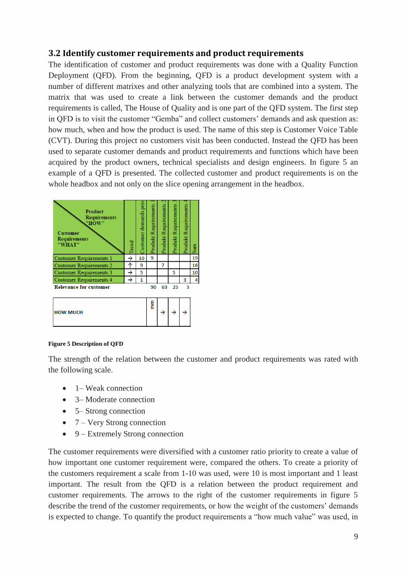
3.2 Identify customer requirements and product requirements The identification of customer and product requirements was done with a Quality Function
Deployment (QFD). From the beginning, QFD is a product development system with a
number of different matrixes and other analyzing tools that are combined into a system. The
matrix that was used to create a link between the customer demands and the product
requirements is called, The House of Quality and is one part of the QFD system. The first step
in QFD is to visit the customer “Gemba” and collect customers’ demands and ask question as:
how much, when and how the product is used. The name of this step is Customer Voice Table
(CVT). During this project no customers visit has been conducted. Instead the QFD has been
used to separate customer demands and product requirements and functions which have been
acquired by the product owners, technical specialists and design engineers. In figure 5 an
example of a QFD is presented. The collected customer and product requirements is on the
whole headbox and not only on the slice opening arrangement in the headbox.
Figure 5 Description of QFD
The strength of the relation between the customer and product requirements was rated with
the following scale.
1– Weak connection
3– Moderate connection
5– Strong connection
7 – Very Strong connection
9 – Extremely Strong connection
The customer requirements were diversified with a customer ratio priority to create a value of
how important one customer requirement were, compared the others. To create a priority of
the customers requirement a scale from 1-10 was used, were 10 is most important and 1 least
important. The result from the QFD is a relation between the product requirement and
customer requirements. The arrows to the right of the customer requirements in figure 5
describe the trend of the customer requirements, or how the weight of the customers’ demands
is expected to change. To quantify the product requirements a “how much value” was used, in
10
the case where it is hard to quantify a number or span, an arrow was used instead to describe
if the product where requirement should be improved (↑), unchanged (→) or reduced (↓)
compared to the current design.
To analyze the QFD matrix the following approaches was used.
Empty row – Indicate a customer demand without a product requirement, additional
product requirement should be added
Empty column –Indicate that a product requirement does not satisfy any customer
demand, therefore it is not a necessary product requirement.
Row without strong connections- Is hard to fulfill, investigated if some product
requirement is missing that can give a strong relation
Row or column with identical connection- Indicate problem with the hierarchy, a
number of connections are expressing the same thing
These are the main points the structure in the QFD has been analyzed from. The QFD matrix
role in the project is as a tool for documentation and discussion and during the project the
QFD has been modified a number of times. The result from the QFD should be seen as a
priority of which product requirement that is most important and which customer
requirements that is easiest or hardest to fulfill. (Gustafsson, 1998)
3.3 Concept generation During the concept generation a number of methods were used. The concept generation was
divided in to two parts: one individual concept generation and one group session concept
generation. The reason that different concept generation methods were used, as Taylor (1966)
describes, is that every person has the possibility to think productively, but commonly it is
only utilized on a small scale. To be able to use this creative potential and exploit it in a
greater extent, some concept generation techniques were applied to the problem to break the
comfort zone. (Taylor, 1966)
3.3.1 Explore systematically
The aim of the external systematical method was to find solutions to the whole problem or
sub problems. The systematical methods which have been used are search patents, search
literature and benchmark related products. By searching patents knowledge and understanding
was achieved about how others have solved the same type of problem. Literature was used to
create fundamental information about design and components. Benchmarking of related
products was used to understand what characterize their competitors’ products. (Ulrich and
Eppinger 2008)
3.3.2 Osborn idea spore
The basic idea behind this method is to change the size of the components or replace it with
something else. Some of the questions that are asked during this method is to enlarge, reduce
size, change position or do the opposite (Johannesson, 2004)
11
3.3.3 Theory of inventive Problem Solving (TIPS)
To solve a problem in a successful and innovative way there are some important underlying
fundamental things. The following principles are the most fundamental. (Johannesson, 2004)
Engineering contractions, separating the problem in time and place
Segmenting a technical solution
Predict natural development step
Predict expected functions
3.3.4 Brainstorming
To include the design engineer of the Headbox in a natural way in the idegenerating, the idea
generation tool brainstorming was used. The brainstorming was conducted in the following
way, 5 minutes presentation of the problem, 15minutes of individual idea generation and 25
minutes discussion of different solutions. The following things are important during the
brainstorming. (Johannesson, 2004)
Criticism is not allowed
Quantity is important
Step outside the box, unusual ideas are welcome
Combine ideas and create new
3.3.5 Random words
After the problem had been explored with the systematical methods, the more abstract idea
generation method random words were implemented on the problem. The thought behind this
concept is to create a list of random words, and go true the list of words and document the
association with the problem. It is important not to analyze the associations too much and
instead just write down the first thought. (Johannesson, 2004)
3.3.6 Documentation of concepts
During the concept generation the ideas are written down with pen and paper.
3.4 Concept selection
3.4.1 Elimination matrix
The elimination matrix is a method for narrowing down the number of concepts. It is a rough
evaluating tool that eliminates the poor solutions. The concept screening matrix evaluates the
following things. (Johannesson, 2004)
Solve the main problem
Meets the requirements of the specification
Is it realizable?
Within cost frame?
Is it safe and reliable?
Is the solution in line with the company’s current solution?
12
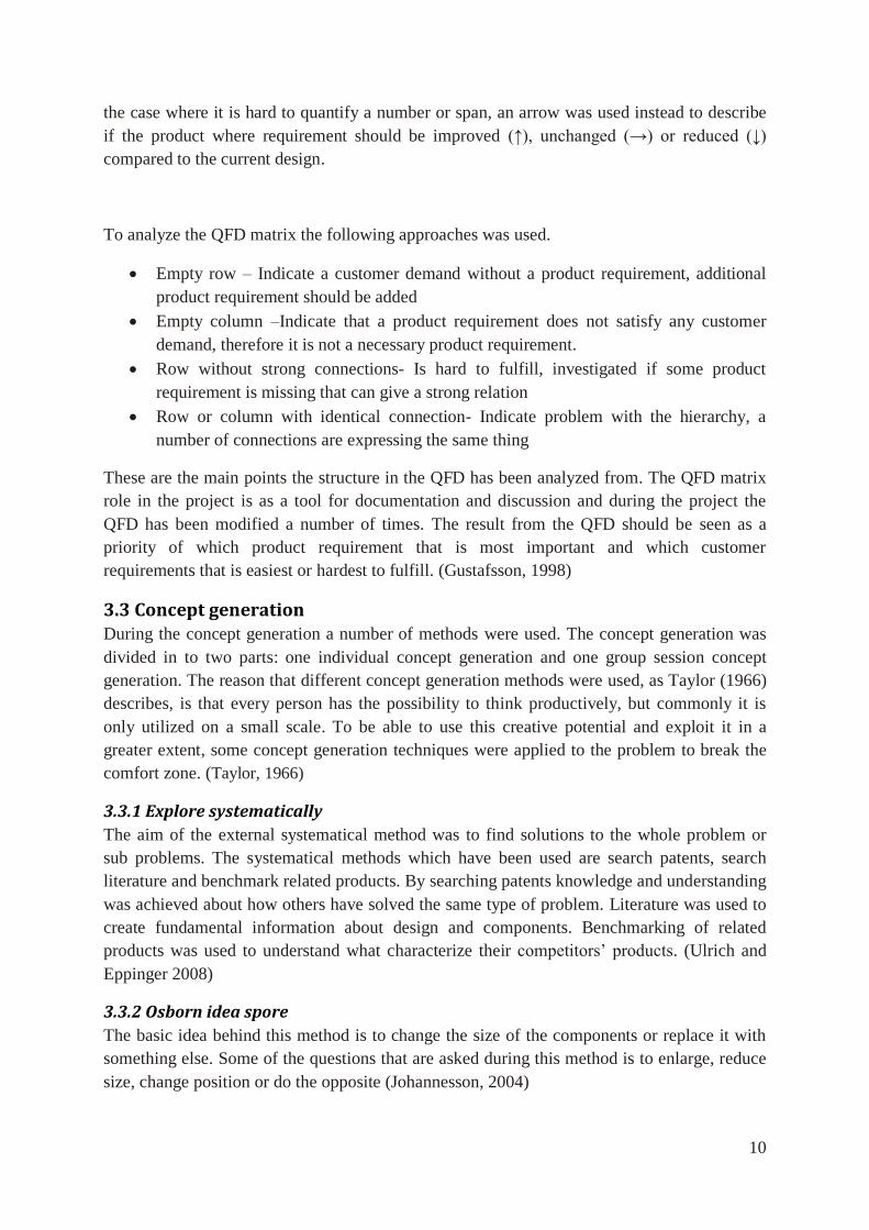
3.4.2 Analytic hierarchy process
Analytic hierarchy process (AHP) is a Multi Critera decision making method that is used for
dealing with complex decision making processes. This method is based on the mythology of
derive ratio scales from pair wise comparison. The input data in the comparison can be price,
length or from a subjective opinion such as complexity or satisfaction. The mathematical
principle behind the AHP is derived from mathematic knowledge about calculation of
eigenvectors, with matrix multiplication and inverse calculations. The product requirements
were divided in criteria’s and sub-criteria’s and evaluated against the alternatives. To
visualize how the hierarchy in AHP is designed, the decision making for a purchase of a car is
used, see figure 6.
Figure 6 Example of AHP hierarchy structure
After the pair wise comparison has been conducted for the whole hierarchy the result can be
analyzed by doing a sensibility analysis of the result. Some examples of questions that can be
analyzed are:
Which criteria or sub-criteria affect the result most?
What would happen if the importance of one criteria is changed, when would
another alternative be preferable?
To further analyze the pair-wise comparison and the weights of the criteria’s and sub
criteria’s. It is possible to measure a consistency index for every matrix created by the pair
wise comparison, to visualize how consistent the different decisions are. The program that
was used to do the AHP, is the internet based Java plug in program Web-HIPRE. The
acceptable inconsistency in the pair wise comparison was set to 10%. (Vaidaya 2006)(Mann
1995)
3.5 3D-design The 3D-models that are presented in the result and used in the Finite element analysis (FEA)
are created with Catia V5.
13
3.6 Finite element analysis This section will describe the simulation of the apron beam and the slice wedge. The
simulations were conducted in the software Ansys R14, 5 professional. Limiting factor in both
cases has been the elastic deformations which have therefore been the main focus in both
simulations.
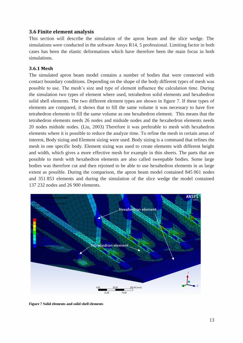
3.6.1 Mesh
The simulated apron beam model contains a number of bodies that were connected with
contact boundary conditions. Depending on the shape of the body different types of mesh was
possible to use. The mesh’s size and type of element influence the calculation time. During
the simulation two types of element where used, tetrahedron solid elements and hexahedron
solid shell elements. The two different element types are shown in figure 7. If these types of
elements are compared, it shows that to fill the same volume it was necessary to have five
tetrahedron elements to fill the same volume as one hexahedron element. This means that the
tetrahedron elements needs 26 nodes and midside nodes and the hexahedron elements needs
20 nodes midside nodes. (Liu, 2003) Therefore it was preferable to mesh with hexahedron
elements where it is possible to reduce the analyze time. To refine the mesh in certain areas of
interest, Body sizing and Element sizing were used. Body sizing is a command that refines the
mesh in one specific body. Element sizing was used to create elements with different height
and width, which gives a more effective mesh for example in thin sheets. The parts that are
possible to mesh with hexahedron elements are also called sweepable bodies. Some large
bodies was therefore cut and then rejoined to be able to use hexahedron elements in as large
extent as possible. During the comparison, the apron beam model contained 845 061 nodes
and 351 853 elements and during the simulation of the slice wedge the model contained
137 232 nodes and 26 900 elements.
Figure 7 Solid elements and solid shell elements
14
3.6.2 Simulation of apron beam
The aim of the simulation of the apron beam was to compare the elastic deformation in the
current design with a modified apron beam.
3.6.2.1 Simplifications
Since the aim of this simulation was to compare the current apron beam with a thinner new
one, the real Apron beam that is 8000mm and has 8 jack attachment points was sliced into a
smaller piece to reduce the calculation time. The apron beam was sliced around one jack
attachment point into a symmetrical part, the width of the simulated models are 990mm.
To simplify, the mesh holes and small chamfers were removed. Instead of meshing the upper
rod of the micro adjustment arrangement, it was modeled as a spring, see figure 3 and 8. The
material properties for the spring are calculated with equation 1 and 2. The maximum force
that can be applied from the current micro adjuster is 5000N. (Tasowheel 2013) The original
length (l0) of the rod is 570mm and the diameter of the rod is between 20-40mm. Depending
on the diameter the spring constant is between 116 280 N/mm and 463 000 N/mm. The same
type of approximation is used for the jack that adjusts the slice opening. But the diameter of
the jack is 60mm and the length is 800mm, if equation 1 and 2 is used the calculated spring
constant for the jack spring is 1 267 000N/mm, see figure 7. To evaluate the effect on the
result, a comparison of different precision adjustment spring constants are presented in
chapter 5.1.
(1)
(2)
15
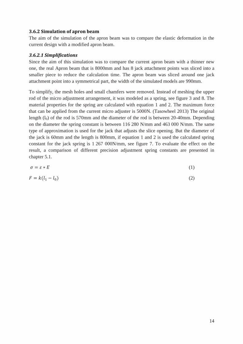
3.6.2.2 Boundary conditions and applied loads
The following boundary conditions and loads were applied to the apron beam models.
Cylindrical support allows the apron beam to rotate around the guide in the back of the apron
beam. Frictionless support is applied to the slice surfaces to only allow movement in the
sliced plane. Instead of using rods to link the micro adjustment together, cylindrical and
revolve joints with elastic contact are used. The difference between the cylindrical and
revolve joints are how much movement that is allowed in the CD. It means that the revolve
joint allows some gap in CD. Figure 8 shows a description of the positions of the boundary
conditions in the apron beam.
Figure 8 Description of boundary conditions in apron beam
In the first model the pressure was assumed to be constant 0,7MPa calculated with Bernoulli’s
equation. In operation conditions the surface under the apron beam is exposed of a variable
pressure from the water fiber suspension. To calculate the variable pressure Bernoulli’s
equation is also used with other boundary conditions. The boundary conditions are
confidential and will not be presented. The presented result contains both simulations with
constant and variable pressure to simulate the reality as much as possible. The used approach
has similarities to the method Zang (2001) used.
16
3.6.3 Simulation of slice wedge
The aim of the simulation of the slice wedge was to understand the elastic deformation
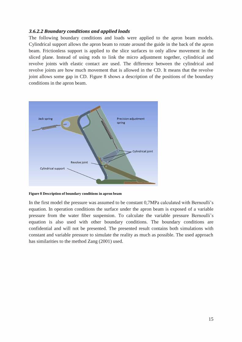
3.6.3.1 Boundary conditions and applied loads
During the simulation of the slice, wedge cylindrical support was applied on the cylindrical
surface also called guide. The other boundary condition applied on the model was a
compression only boundary conditions which only restrict movement upward in the vertical
direction for the slice wedge. And a constant pressure of 0,7MPa was applied to simulate the
pressure from the waterfiber suspension, See figure 9. If the pressure load is applied in one
step it is hard for the model to converge. To reduce the calculation time the load was applied
in two steps, first at the surface on the opposite side of the boundary condition compression
only. Then the pressure was also applied on the free length of the wedge. To further decrease
the calculation time the increment in step 2 was reduced with a factor of 10 from 1 to 0, 1.
Figure 9 Boundary conditions and applied loads to the slice wedge
3.7 Material selection The material selection is conducted and motivated with the program CES Edupack and
appropriate literature.
17
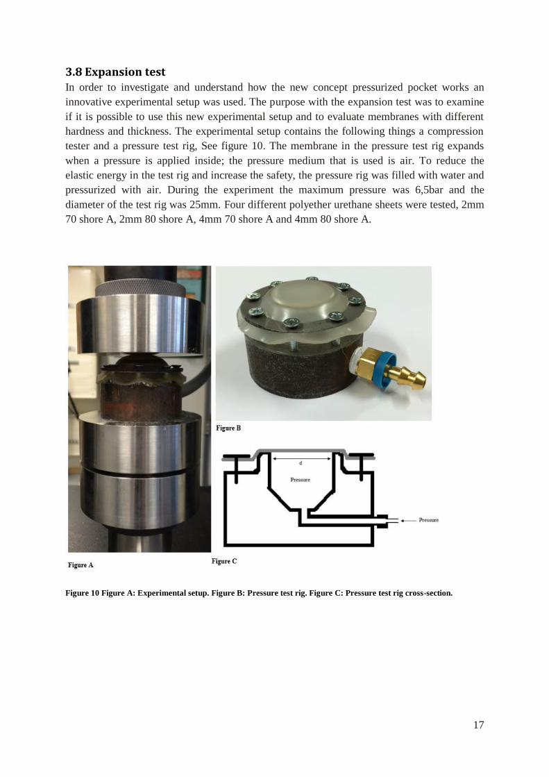
3.8 Expansion test In order to investigate and understand how the new concept pressurized pocket works an
innovative experimental setup was used. The purpose with the expansion test was to examine
if it is possible to use this new experimental setup and to evaluate membranes with different
hardness and thickness. The experimental setup contains the following things a compression
tester and a pressure test rig, See figure 10. The membrane in the pressure test rig expands
when a pressure is applied inside; the pressure medium that is used is air. To reduce the
elastic energy in the test rig and increase the safety, the pressure rig was filled with water and
pressurized with air. During the experiment the maximum pressure was 6,5bar and the
diameter of the test rig was 25mm. Four different polyether urethane sheets were tested, 2mm
70 shore A, 2mm 80 shore A, 4mm 70 shore A and 4mm 80 shore A.
Figure 10 Figure A: Experimental setup. Figure B: Pressure test rig. Figure C: Pressure test rig cross-section.
18
4. Results
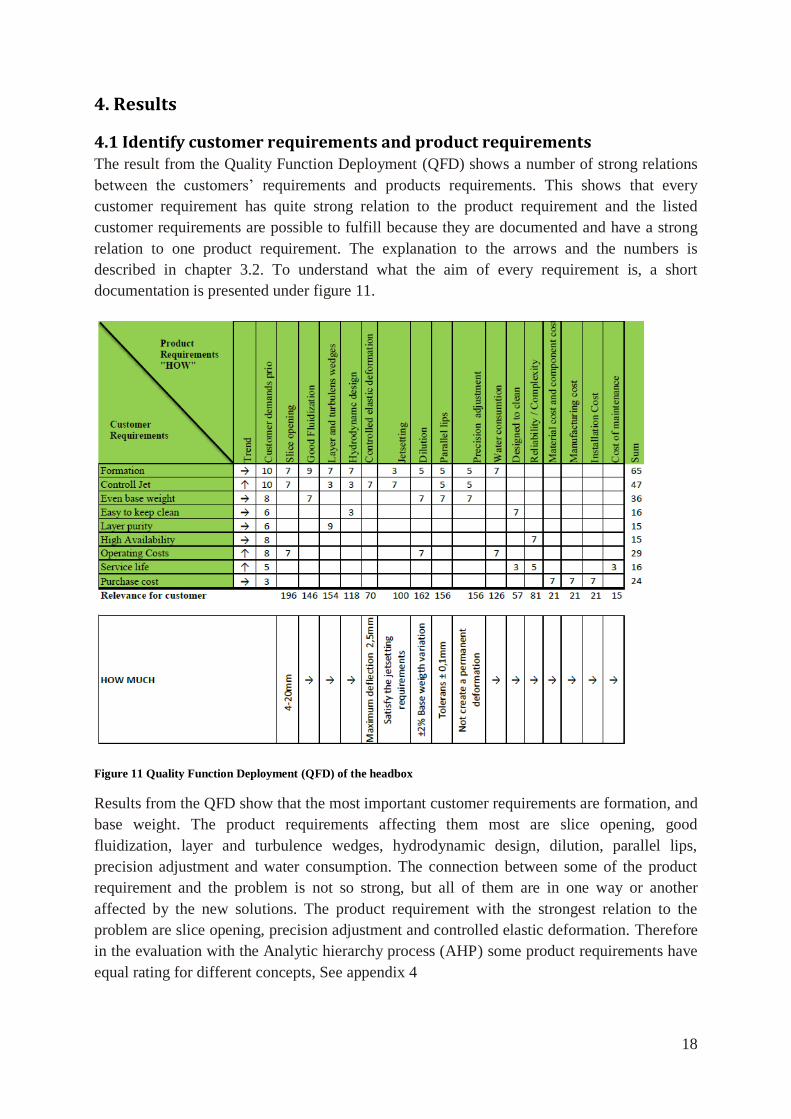
4.1 Identify customer requirements and product requirements The result from the Quality Function Deployment (QFD) shows a number of strong relations
between the customers’ requirements and products requirements. This shows that every
customer requirement has quite strong relation to the product requirement and the listed
customer requirements are possible to fulfill because they are documented and have a strong
relation to one product requirement. The explanation to the arrows and the numbers is
described in chapter 3.2. To understand what the aim of every requirement is, a short
documentation is presented under figure 11.
Figure 11 Quality Function Deployment (QFD) of the headbox
Results from the QFD show that the most important customer requirements are formation, and
base weight. The product requirements affecting them most are slice opening, good
fluidization, layer and turbulence wedges, hydrodynamic design, dilution, parallel lips,
precision adjustment and water consumption. The connection between some of the product
requirement and the problem is not so strong, but all of them are in one way or another
affected by the new solutions. The product requirement with the strongest relation to the
problem are slice opening, precision adjustment and controlled elastic deformation. Therefore
in the evaluation with the Analytic hierarchy process (AHP) some product requirements have
equal rating for different concepts, See appendix 4
19
Slice opening – The distance between the slice lips. The purpose of the slice opening is to
adjust the thickness of the jet that enters the headbox. Depending on the slice opening,
different amount of energy is consumed. But if more water is used, the produced paper
formation gets better.
Good Fluidization – Higher fluidization minimize the flocs in the final paper and increase
the formation.
Layer and turbulence wedges – The purpose of the turbulence wedges is to reduce the
motion in the fluid and the layer wedges is used to separate different mixtures of water fiber
suspension.
Hydrodynamic design –The design of the Headbox should not disturb the flow and decrease
the quality of the paper
Controlled deflection – The elastic deformation in the headbox should be well controlled and
the effect on the gap should be less than 2,5mm
Jet setting – Possibility to adjust the jet parameters that is described in chapter 2, 2.
Dilution –The base weight is adjusted with a number of extra flows to dilute the waterfiber
suspension where it is necessary.
Parallel lips – To obtain an even exiting flow from the headbox
Precision adjustment – The only way to adjust the base weight in headboxes that not have
dilution
Water consumption – Is dependent on the machine speed and slice opening
Designed to clean – The design of the headbox should be easy to clean
Material cost and component cost – The cost of material and standard components
Manufacturing cost – Manufacturing cost for components in the headbox
Installation Cost – Assembly cost for the whole headbox
Cost of maintenance – To design the headbox so it is easy to do scheduled maintenance
20
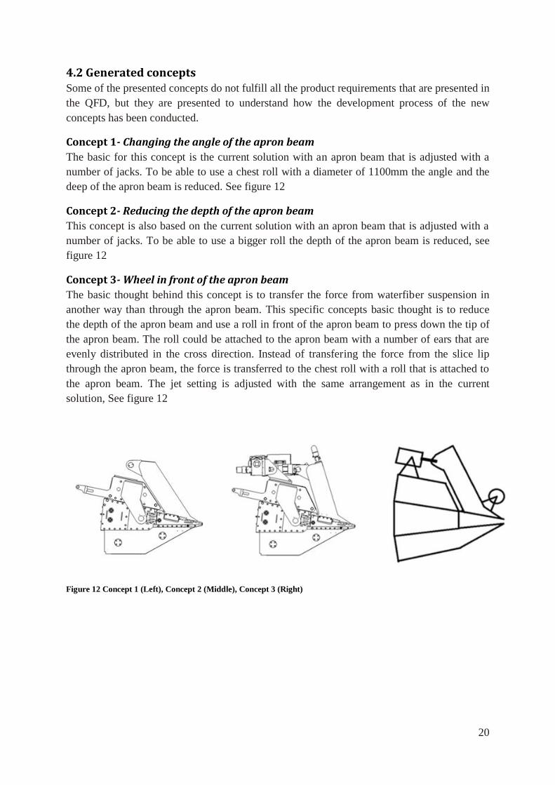
4.2 Generated concepts Some of the presented concepts do not fulfill all the product requirements that are presented in
the QFD, but they are presented to understand how the development process of the new
concepts has been conducted.
Concept 1- Changing the angle of the apron beam
The basic for this concept is the current solution with an apron beam that is adjusted with a
number of jacks. To be able to use a chest roll with a diameter of 1100mm the angle and the
deep of the apron beam is reduced. See figure 12
Concept 2- Reducing the depth of the apron beam
This concept is also based on the current solution with an apron beam that is adjusted with a
number of jacks. To be able to use a bigger roll the depth of the apron beam is reduced, see
figure 12
Concept 3- Wheel in front of the apron beam
The basic thought behind this concept is to transfer the force from waterfiber suspension in
another way than through the apron beam. This specific concepts basic thought is to reduce
the depth of the apron beam and use a roll in front of the apron beam to press down the tip of
the apron beam. The roll could be attached to the apron beam with a number of ears that are
evenly distributed in the cross direction. Instead of transfering the force from the slice lip
through the apron beam, the force is transferred to the chest roll with a roll that is attached to
the apron beam. The jet setting is adjusted with the same arrangement as in the current
solution, See figure 12
Figure 12 Concept 1 (Left), Concept 2 (Middle), Concept 3 (Right)
21
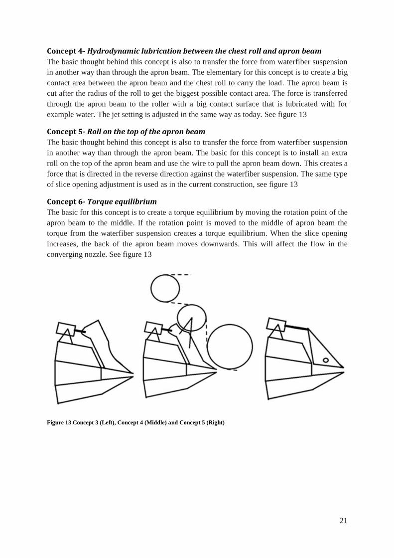
Concept 4- Hydrodynamic lubrication between the chest roll and apron beam
The basic thought behind this concept is also to transfer the force from waterfiber suspension
in another way than through the apron beam. The elementary for this concept is to create a big
contact area between the apron beam and the chest roll to carry the load. The apron beam is
cut after the radius of the roll to get the biggest possible contact area. The force is transferred
through the apron beam to the roller with a big contact surface that is lubricated with for
example water. The jet setting is adjusted in the same way as today. See figure 13
Concept 5- Roll on the top of the apron beam
The basic thought behind this concept is also to transfer the force from waterfiber suspension
in another way than through the apron beam. The basic for this concept is to install an extra
roll on the top of the apron beam and use the wire to pull the apron beam down. This creates a
force that is directed in the reverse direction against the waterfiber suspension. The same type
of slice opening adjustment is used as in the current construction, see figure 13
Concept 6- Torque equilibrium
The basic for this concept is to create a torque equilibrium by moving the rotation point of the
apron beam to the middle. If the rotation point is moved to the middle of apron beam the
torque from the waterfiber suspension creates a torque equilibrium. When the slice opening
increases, the back of the apron beam moves downwards. This will affect the flow in the
converging nozzle. See figure 13
Figure 13 Concept 3 (Left), Concept 4 (Middle) and Concept 5 (Right)
22
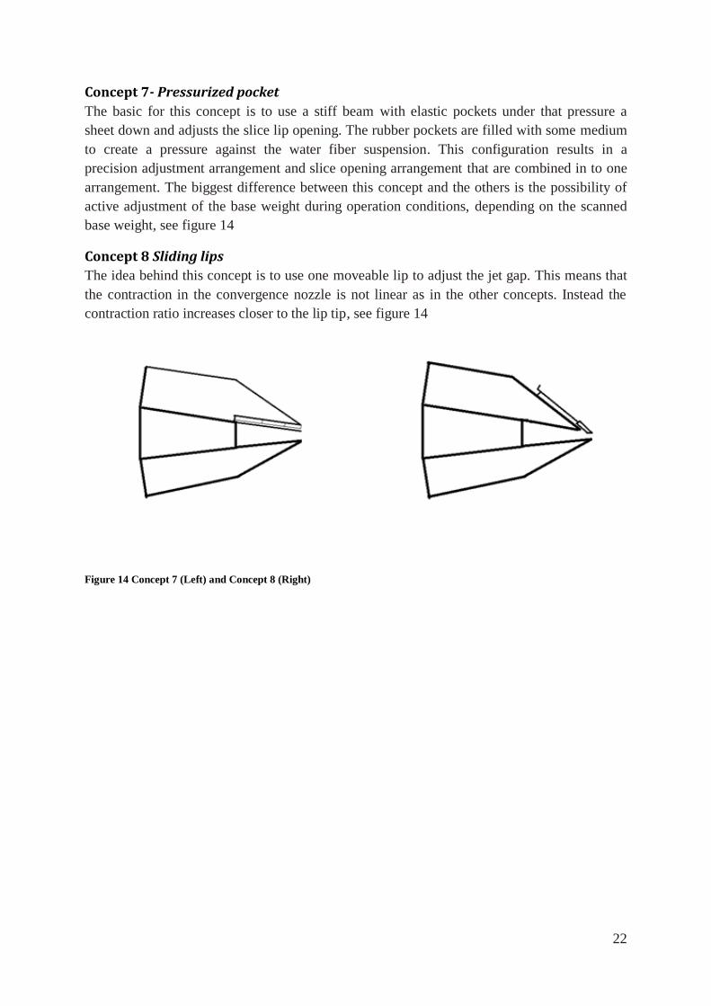
Concept 7- Pressurized pocket
The basic for this concept is to use a stiff beam with elastic pockets under that pressure a
sheet down and adjusts the slice lip opening. The rubber pockets are filled with some medium
to create a pressure against the water fiber suspension. This configuration results in a
precision adjustment arrangement and slice opening arrangement that are combined in to one
arrangement. The biggest difference between this concept and the others is the possibility of
active adjustment of the base weight during operation conditions, depending on the scanned
base weight, see figure 14
Concept 8 Sliding lips
The idea behind this concept is to use one moveable lip to adjust the jet gap. This means that
the contraction in the convergence nozzle is not linear as in the other concepts. Instead the
contraction ratio increases closer to the lip tip, see figure 14
Figure 14 Concept 7 (Left) and Concept 8 (Right)
23
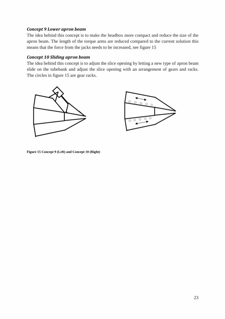
Concept 9 Lower apron beam
The idea behind this concept is to make the headbox more compact and reduce the size of the
apron beam. The length of the torque arms are reduced compared to the current solution this
means that the force from the jacks needs to be increased, see figure 15
Concept 10 Sliding apron beam
The idea behind this concept is to adjust the slice opening by letting a new type of apron beam
slide on the tubebank and adjust the slice opening with an arrangement of gears and racks.
The circles in figure 15 are gear racks.
Figure 15 Concept 9 (Left) and Concept 10 (Right)
24
4.3 Concept selection
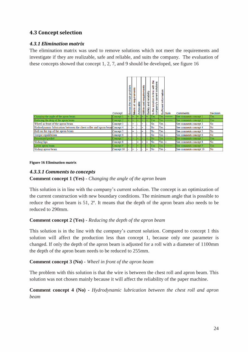
4.3.1 Elimination matrix
The elimination matrix was used to remove solutions which not meet the requirements and
investigate if they are realizable, safe and reliable, and suits the company. The evaluation of
these concepts showed that concept 1, 2, 7, and 9 should be developed, see figure 16
Figure 16 Elimination matrix
4.3.3.1 Comments to concepts
Comment concept 1 (Yes) - Changing the angle of the apron beam
This solution is in line with the company’s current solution. The concept is an optimization of
the current construction with new boundary conditions. The minimum angle that is possible to
reduce the apron beam is 51, 2º. It means that the depth of the apron beam also needs to be
reduced to 290mm.
Comment concept 2 (Yes) - Reducing the depth of the apron beam
This solution is in the line with the company’s current solution. Compared to concept 1 this
solution will affect the production less than concept 1, because only one parameter is
changed. If only the depth of the apron beam is adjusted for a roll with a diameter of 1100mm
the depth of the apron beam needs to be reduced to 255mm.
Comment concept 3 (No) - Wheel in front of the apron beam
The problem with this solution is that the wire is between the chest roll and apron beam. This
solution was not chosen mainly because it will affect the reliability of the paper machine.
Comment concept 4 (No) - Hydrodynamic lubrication between the chest roll and apron
beam
25
The problem with this solution is the same as concept 3. The wire is between chest roll and
apron beam and was not chosen mainly because it will affect the reliability of the paper
machine.
Comment concept 5 (No) - Roll on the top of the apron beam
This solution was not chosen because the dimensions of the roll needs to be in the same
dimensions as the chest roll to withstand the force from the wire and the deflection from its
own weight. The ears on the apron beam needs to quite large to be able hold the roll and
transferring the force from the apron beam to the roll. Therefore this solution was not chosen.
Comment concept 6 (No) - Torque equilibrium
This solution was not chosen because the problem with this concept is that the flow will be
affected in a negative by the moving pattern of the apron beam.
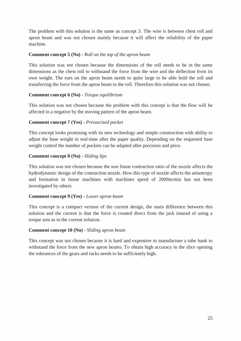
Comment concept 7 (Yes) - Pressurized pocket
This concept looks promising with its new technology and simple construction with ability to
adjust the base weight in real-time after the paper quality. Depending on the requested base
weight control the number of pockets can be adapted after precision and price.
Comment concept 8 (No) - Sliding lips
This solution was not chosen because the non linear contraction ratio of the nozzle affects the
hydrodynamic design of the contraction nozzle. How this type of nozzle affects the anisotropy
and formation in tissue machines with machines speed of 2000m/min has not been
investigated by others.
Comment concept 9 (Yes) - Lower apron beam
This concept is a compact version of the current design, the main difference between this
solution and the current is that the force is created direct from the jack instead of using a
torque arm as in the current solution.
Comment concept 10 (No) - Sliding apron beam
This concept was not chosen because it is hard and expensive to manufacture a tube bank to
withstand the force from the new apron beams. To obtain high accuracy in the slice opening
the tolerances of the gears and racks needs to be sufficiently high.
26
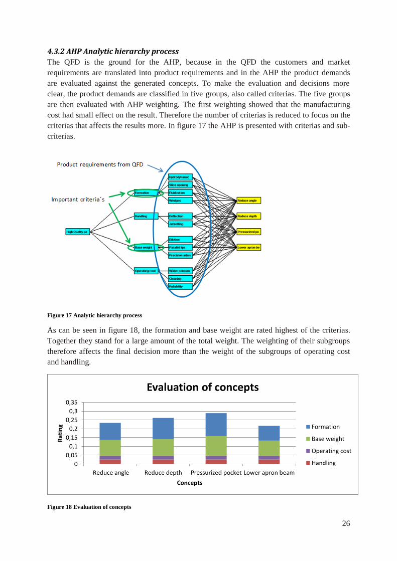
4.3.2 AHP Analytic hierarchy process
The QFD is the ground for the AHP, because in the QFD the customers and market
requirements are translated into product requirements and in the AHP the product demands
are evaluated against the generated concepts. To make the evaluation and decisions more
clear, the product demands are classified in five groups, also called criterias. The five groups
are then evaluated with AHP weighting. The first weighting showed that the manufacturing
cost had small effect on the result. Therefore the number of criterias is reduced to focus on the
criterias that affects the results more. In figure 17 the AHP is presented with criterias and sub-
criterias.
Figure 17 Analytic hierarchy process
As can be seen in figure 18, the formation and base weight are rated highest of the criterias.
Together they stand for a large amount of the total weight. The weighting of their subgroups
therefore affects the final decision more than the weight of the subgroups of operating cost
and handling.
Figure 18 Evaluation of concepts
0
0,05
0,1
0,15
0,2
0,25
0,3
0,35
Reduce angle Reduce depth Pressurized pocket Lower apron beam
Rat
ing
Concepts
Evaluation of concepts
Formation
Base weight
Operating cost
Handling
27
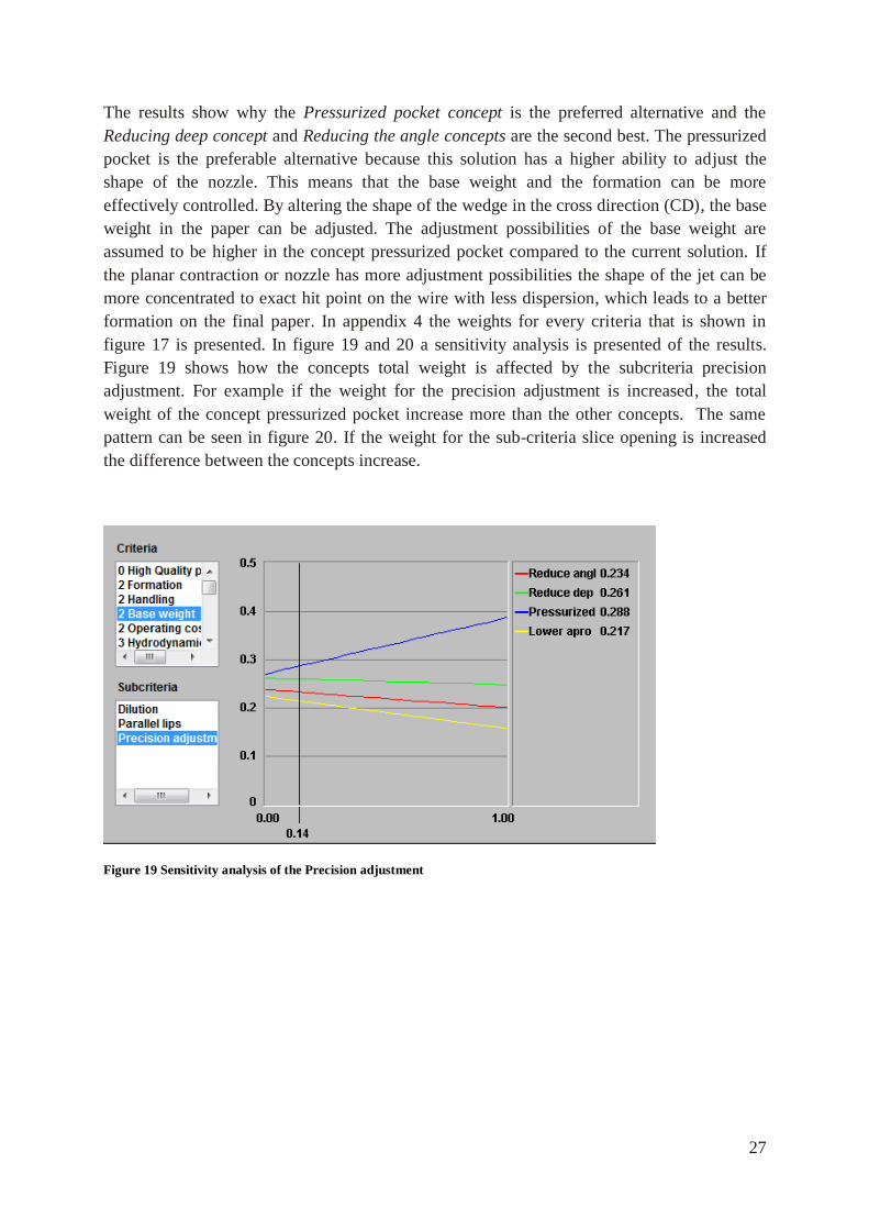
The results show why the Pressurized pocket concept is the preferred alternative and the
Reducing deep concept and Reducing the angle concepts are the second best. The pressurized
pocket is the preferable alternative because this solution has a higher ability to adjust the
shape of the nozzle. This means that the base weight and the formation can be more
effectively controlled. By altering the shape of the wedge in the cross direction (CD), the base
weight in the paper can be adjusted. The adjustment possibilities of the base weight are
assumed to be higher in the concept pressurized pocket compared to the current solution. If
the planar contraction or nozzle has more adjustment possibilities the shape of the jet can be
more concentrated to exact hit point on the wire with less dispersion, which leads to a better
formation on the final paper. In appendix 4 the weights for every criteria that is shown in
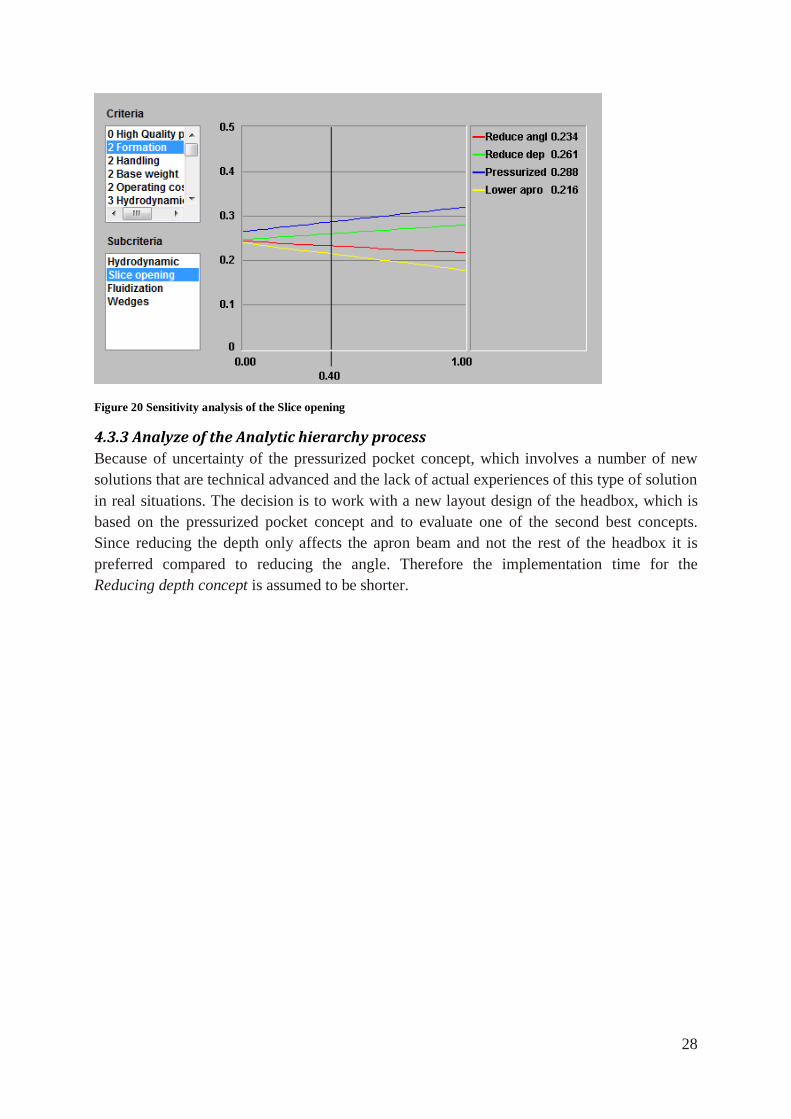
figure 17 is presented. In figure 19 and 20 a sensitivity analysis is presented of the results.
Figure 19 shows how the concepts total weight is affected by the subcriteria precision
adjustment. For example if the weight for the precision adjustment is increased, the total
weight of the concept pressurized pocket increase more than the other concepts. The same
pattern can be seen in figure 20. If the weight for the sub-criteria slice opening is increased
the difference between the concepts increase.
Figure 19 Sensitivity analysis of the Precision adjustment
28
Figure 20 Sensitivity analysis of the Slice opening
4.3.3 Analyze of the Analytic hierarchy process
Because of uncertainty of the pressurized pocket concept, which involves a number of new
solutions that are technical advanced and the lack of actual experiences of this type of solution
in real situations. The decision is to work with a new layout design of the headbox, which is
based on the pressurized pocket concept and to evaluate one of the second best concepts.
Since reducing the depth only affects the apron beam and not the rest of the headbox it is
preferred compared to reducing the angle. Therefore the implementation time for the
Reducing depth concept is assumed to be shorter.
29
5. Design of modified apron beam
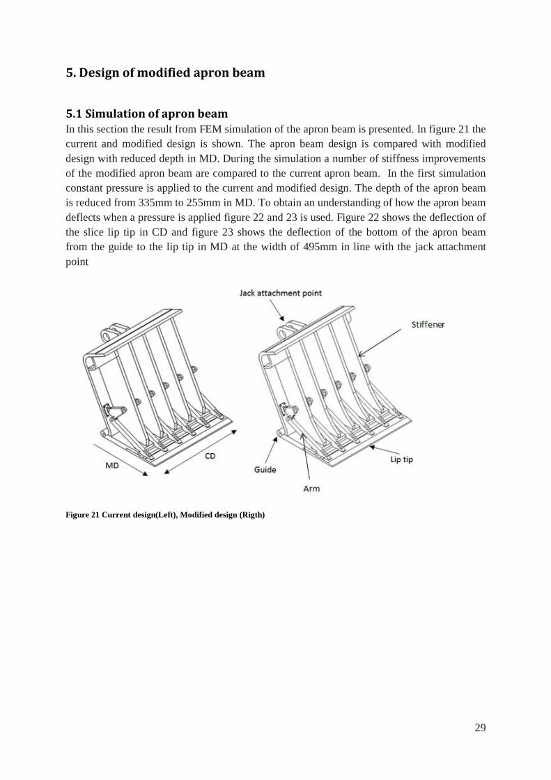
5.1 Simulation of apron beam In this section the result from FEM simulation of the apron beam is presented. In figure 21 the
current and modified design is shown. The apron beam design is compared with modified
design with reduced depth in MD. During the simulation a number of stiffness improvements
of the modified apron beam are compared to the current apron beam. In the first simulation
constant pressure is applied to the current and modified design. The depth of the apron beam
is reduced from 335mm to 255mm in MD. To obtain an understanding of how the apron beam
deflects when a pressure is applied figure 22 and 23 is used. Figure 22 shows the deflection of
the slice lip tip in CD and figure 23 shows the deflection of the bottom of the apron beam
from the guide to the lip tip in MD at the width of 495mm in line with the jack attachment
point
Figure 21 Current design(Left), Modified design (Rigth)
30
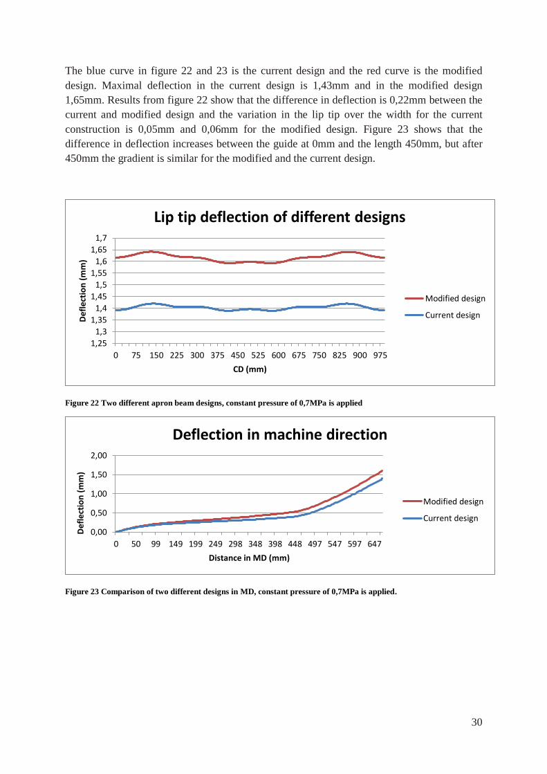
The blue curve in figure 22 and 23 is the current design and the red curve is the modified
design. Maximal deflection in the current design is 1,43mm and in the modified design
1,65mm. Results from figure 22 show that the difference in deflection is 0,22mm between the
current and modified design and the variation in the lip tip over the width for the current
construction is 0,05mm and 0,06mm for the modified design. Figure 23 shows that the
difference in deflection increases between the guide at 0mm and the length 450mm, but after
450mm the gradient is similar for the modified and the current design.
Figure 22 Two different apron beam designs, constant pressure of 0,7MPa is applied
Figure 23 Comparison of two different designs in MD, constant pressure of 0,7MPa is applied.
1,25
1,3
1,35
1,4
1,45
1,5
1,55
1,6
1,65
1,7
0 75 150 225 300 375 450 525 600 675 750 825 900 975
Def
lect
ion
(m
m)
CD (mm)
Lip tip deflection of different designs
Modified design
Current design
0,00
0,50
1,00
1,50
2,00
0 50 99 149 199 249 298 348 398 448 497 547 597 647
Def
lect
ion
(m
m)
Distance in MD (mm)
Deflection in machine direction
Modified design
Current design
31
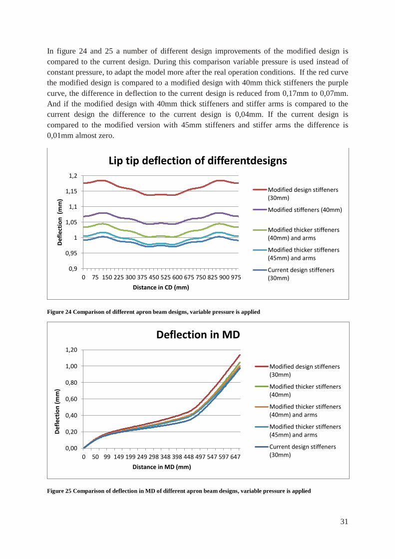
In figure 24 and 25 a number of different design improvements of the modified design is
compared to the current design. During this comparison variable pressure is used instead of
constant pressure, to adapt the model more after the real operation conditions. If the red curve
the modified design is compared to a modified design with 40mm thick stiffeners the purple
curve, the difference in deflection to the current design is reduced from 0,17mm to 0,07mm.
And if the modified design with 40mm thick stiffeners and stiffer arms is compared to the
current design the difference to the current design is 0,04mm. If the current design is
compared to the modified version with 45mm stiffeners and stiffer arms the difference is
0,01mm almost zero.
Figure 24 Comparison of different apron beam designs, variable pressure is applied
Figure 25 Comparison of deflection in MD of different apron beam designs, variable pressure is applied
0,9
0,95
1
1,05
1,1
1,15
1,2
0 75 150 225 300 375 450 525 600 675 750 825 900 975
Def
lect
ion
(m
m)
Distance in CD (mm)
Lip tip deflection of differentdesigns
Modified design stiffeners(30mm)
Modified stiffeners (40mm)
Modified thicker stiffeners(40mm) and arms
Modified thicker stiffeners(45mm) and arms
Current design stiffeners(30mm)
0,00
0,20
0,40
0,60
0,80
1,00
1,20
0 50 99 149 199 249 298 348 398 448 497 547 597 647
Def
lect
ion
(m
m)
Distance in MD (mm)
Deflection in MD
Modified design stiffeners(30mm)
Modified thicker stiffeners(40mm)
Modified thicker stiffeners(40mm) and arms
Modified thicker stiffeners(45mm) and arms
Current design stiffeners(30mm)
32
If the stiffness improvements in the apron beam are analyzed with the results from figure 26,
they shows that the thickness of the stiffeners affect the total deflection by reducing the
deflection from 0 to 450mm in the MD. The stiffer arms affect the total deflection by reducing
the deflection from 450 to the lip tip.
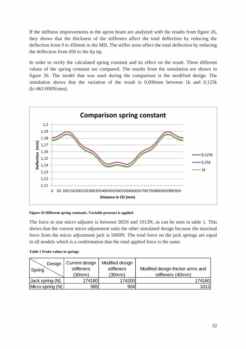
In order to verify the calculated spring constant and its effect on the result. Three different
values of the spring constant are compared. The results from the simulation are shown in
figure 26. The model that was used during the comparison is the modified design. The
simulation shows that the variation of the result is 0,006mm between 1k and 0,125k
(k=463 000N/mm).
Figure 26 Different spring constants. Variable pressure is applied
The force in one micro adjuster is between 585N and 1013N, as can be seen in table 1. This
shows that the current micro adjustment suits the other simulated design because the maximal
force from the micro adjustment jack is 5000N. The total force on the jack springs are equal
in all models which is a confirmation that the total applied force is the same.
Table 1 Probe values in springs
1,11
1,12
1,13
1,14
1,15
1,16
1,17
1,18
1,19
1,2
0 50 100150200250300350400450500550600650700750800850900950
Def
lect
ion
(m
m)
Distance in CD (mm)
Comparison spring constant
0,125k
0,25k
1k
Current design
stiffeners
(30mm)
Modified design
stiffeners
(30mm)
Modified design thicker arms and
stiffeners (40mm)
Jack spring (N) 174180 174200 174160
Micro spring (N) 585 904 1013
Spring
Design
33
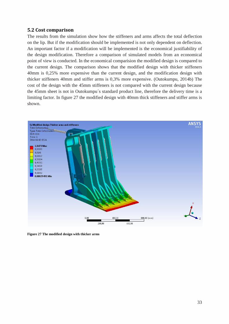
5.2 Cost comparison The results from the simulation show how the stiffeners and arms affects the total deflection
on the lip. But if the modification should be implemented is not only dependent on deflection.
An important factor if a modification will be implemented is the economical justifiability of
the design modification. Therefore a comparison of simulated models from an economical
point of view is conducted. In the economical comparision the modified design is compared to
the current design. The comparison shows that the modified design with thicker stiffeners
40mm is 0,25% more expensive than the current design, and the modification design with
thicker stiffeners 40mm and stiffer arms is 0,3% more expensive. (Outokumpu, 2014b) The
cost of the design with the 45mm stiffeners is not compared with the current design because
the 45mm sheet is not in Outokumpu´s standard product line, therefore the delivery time is a
limiting factor. In figure 27 the modified design with 40mm thick stiffeners and stiffer arms is
shown.
Figure 27 The modified design with thicker arms
34
6. Design of Pressurized pocket
6.1 Description of components in Pressurized pocket The first step in the design process of the pressurized pocket was to determine the limiting
dimensions. This was done by creating a 2D model of the Jet setting where the four factors Jet
impingement, Jet angle, Jet length and slice lip distance could be changed to find the toughest
possible case. How this model was designed is confidential.
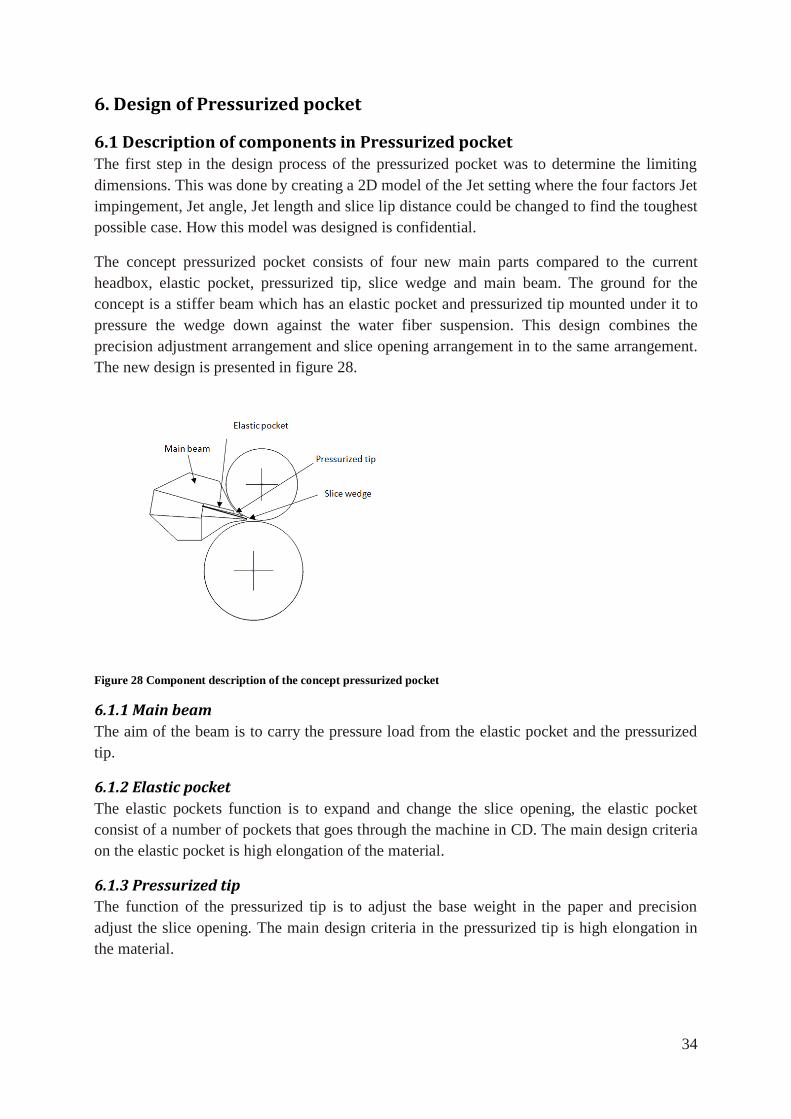
The concept pressurized pocket consists of four new main parts compared to the current
headbox, elastic pocket, pressurized tip, slice wedge and main beam. The ground for the
concept is a stiffer beam which has an elastic pocket and pressurized tip mounted under it to
pressure the wedge down against the water fiber suspension. This design combines the
precision adjustment arrangement and slice opening arrangement in to the same arrangement.
The new design is presented in figure 28.
Figure 28 Component description of the concept pressurized pocket
6.1.1 Main beam
The aim of the beam is to carry the pressure load from the elastic pocket and the pressurized
tip.
6.1.2 Elastic pocket
The elastic pockets function is to expand and change the slice opening, the elastic pocket
consist of a number of pockets that goes through the machine in CD. The main design criteria
on the elastic pocket is high elongation of the material.
6.1.3 Pressurized tip
The function of the pressurized tip is to adjust the base weight in the paper and precision
adjust the slice opening. The main design criteria in the pressurized tip is high elongation in
the material.
35
6.1.4 Slice wedge
The slice wedge is attached to the headbox with the same type of guide as the turbulence and
layer wedges. During operation condition the slice wedge is pressured against the elastic
pocket and pressurized tip, which transfer the pressure from the water fiber suspension to the
main beam. When the fiberwater suspension is switched of, the wedges falls down on the
layer wedge and the slice lip of the roof. The examination of the Jet setting 2D model show
that the slice wedge free length is 130mm from the end of the Main beam. Important design
criterias for the slice wedge are therefore the own weight and stiffness in the tip and the
resistance of absorption of moisture.
6.2 Design of components in Pressurized pocket
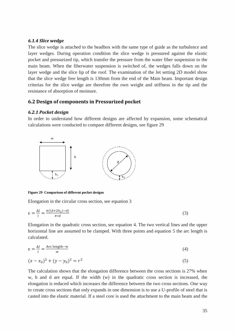
6.2.1 Pocket design
In order to understand how different designs are affected by expansion, some schematical
calculations were conducted to compare different designs, see figure 29
Figure 29 Comparison of different pocket designs
Elongation in the circular cross section, see equation 3
(3)
Elongation in the quadratic cross section, see equation 4. The two vertical lines and the upper
horizontal line are assumed to be clamped. With three points and equation 5 the arc length is
calculated.
(4)
(5)
The calculation shows that the elongation difference between the cross sections is 27% when
w, h and d are equal. If the width (w) in the quadratic cross section is increased, the
elongation is reduced which increases the difference between the two cross sections. One way
to create cross sections that only expands in one dimension is to use a U-profile of steel that is
casted into the elastic material. If a steel core is used the attachment to the main beam and the
36
attachment of hydraulic hoses also gets simpler, for example screw nuts and attachment
nipples for the hydraulic can be mounted before the casting.
6.2.2 Size of pockets
The section size of the paper machine is 60mm, and the section distance between the micro
adjustments, which is used in the current design, is 180mm. The basis for 60mm sections is
the width of two pipes in the turbulence generator. To increase the precision, the width of the
pressurized tip pockets should be 120mm. If it is economically justifiable the width of the
pocket can also be decreased to 60mm. The size of the elastic pocket is dependent on the
manufacturing and service possibilities.
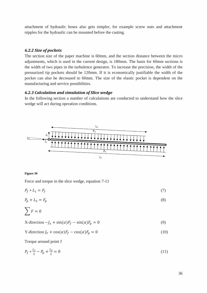
6.2.3 Calculation and simulation of Slice wedge
In the following section a number of calculations are conducted to understand how the slice
wedge will act during operation conditions.
Figure 30
Force and torque in the slice wedge, equation 7-11
(7)
(8)
∑
X-direction (9)
Y-direction (10)
Torque around point J
(11)
37
The following data are inserted in equation 7-11: Pressure from fiber suspension (Pf) =
0,7MPa, Length (L1) =700mm, Length (L2) =570mm and angle α =3º. The calculations of
equation 7-11 shows the following. The pressure from the elastic pocket needs to be (Pp) =
0,86MPa to withstand the pressure from the water fiber suspension and the forces in the guide
are Jx = 0,01 N/mm and Jy = 0, 2 N/mm
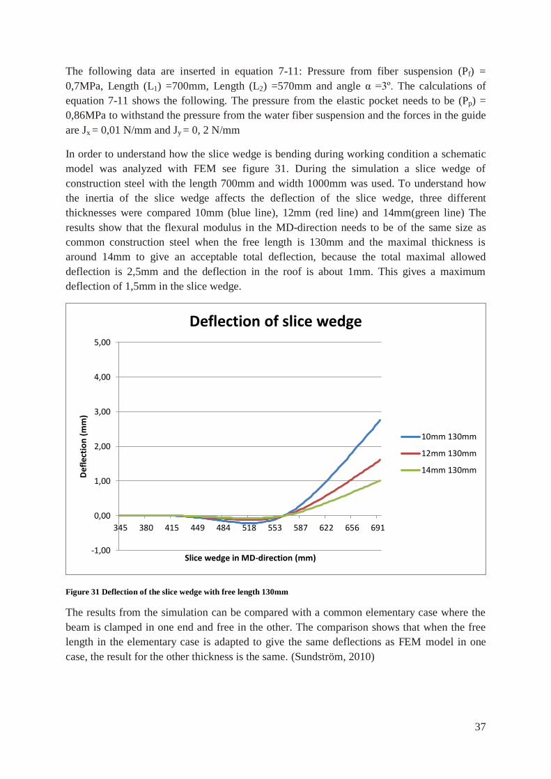
In order to understand how the slice wedge is bending during working condition a schematic
model was analyzed with FEM see figure 31. During the simulation a slice wedge of
construction steel with the length 700mm and width 1000mm was used. To understand how
the inertia of the slice wedge affects the deflection of the slice wedge, three different
thicknesses were compared 10mm (blue line), 12mm (red line) and 14mm(green line) The
results show that the flexural modulus in the MD-direction needs to be of the same size as
common construction steel when the free length is 130mm and the maximal thickness is
around 14mm to give an acceptable total deflection, because the total maximal allowed
deflection is 2,5mm and the deflection in the roof is about 1mm. This gives a maximum
deflection of 1,5mm in the slice wedge.
Figure 31 Deflection of the slice wedge with free length 130mm
The results from the simulation can be compared with a common elementary case where the
beam is clamped in one end and free in the other. The comparison shows that when the free
length in the elementary case is adapted to give the same deflections as FEM model in one
case, the result for the other thickness is the same. (Sundström, 2010)
-1,00
0,00
1,00
2,00
3,00
4,00
5,00
345 380 415 449 484 518 553 587 622 656 691
Def
lect
ion
(m
m)
Slice wedge in MD-direction (mm)
Deflection of slice wedge
10mm 130mm
12mm 130mm
14mm 130mm
38
6.3 Material selection
6.3.1 Material in the main beam
The material in the current design is a duplex stainless steel. This steel has high stiffness and
good corrosion resistance and is appropriate for the main beam also in the new design.
6.3.2 Material with high elongation
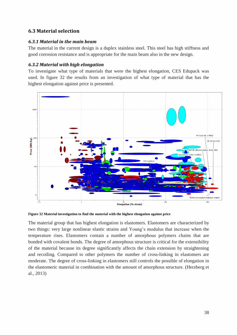
To investigate what type of materials that were the highest elongation, CES Edupack was
used. In figure 32 the results from an investigation of what type of material that has the
highest elongation against price is presented.
Figure 32 Material investigation to find the material with the highest elongation against price
The material group that has highest elongation is elastomers. Elastomers are characterized by
two things: very large nonlinear elastic strains and Young’s modulus that increase when the
temperature rises. Elastomers contain a number of amorphous polymers chains that are
bonded with covalent bonds. The degree of amorphous structure is critical for the extensibility
of the material because its degree significantly affects the chain extension by straightening
and recoiling. Compared to other polymers the number of cross-linking in elastomers are
moderate. The degree of cross-linking in elastomers still controls the possible of elongation in
the elastomeric material in combination with the amount of amorphous structure. (Herzberg et
al., 2013)
39
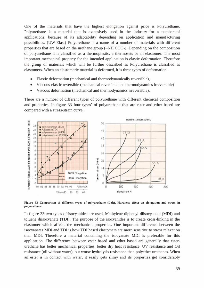
One of the materials that have the highest elongation against price is Polyurethane.
Polyurethane is a material that is extensively used in the industry for a number of
applications, because of its adaptability depending on application and manufacturing
possibilities. (UW-Elast) Polyurethane is a name of a number of materials with different
properties that are based on the urethane group (–NH COO-). Depending on the composition
of polyurethane it is classified as a thermoplastic, a thermosets or an elastomer. The most
important mechanical property for the intended application is elastic deformation. Therefore
the group of materials which will be further described as Polyurethane is classified as
elastomers. When an elastomeric material is deformed, it is three types of deformation.
Elastic deformation (mechanical and thermodynamically reversible),
Viscous-elastic reversible (mechanical reversible and thermodynamics irreversible)
Viscous deformation (mechanical and thermodynamics irreversible).
There are a number of different types of polyurethane with different chemical composition
and properties. In figure 33 four types’ of polyurethane that are ester and ether based are
compared with a stress-strain curve.
Figure 33 Comparison of different types of polyurethane (Left), Hardness effect on elongation and stress in
polyurethane
In figure 33 two types of isocyanides are used, Methylene diphenyl diisocyanate (MDI) and
toluene diisocyanate (TDI). The purpose of the isocyanides is to create cross-linking in the
elastomer which affects the mechanical properties. One important difference between the
isocyanates MDI and TDI is how TDI based elastomers are more sensitive to stress relaxation
than MDI. Therefore a material containing the isocyanate MDI is preferable for this
application. The difference between ester based and ether based are generally that ester-
urethane has better mechanical properties, better dry heat resistance, UV resistance and Oil
resistance (oil without water), but worse hydrolysis resistance than polyether urethanes. When
an ester is in contact with water, it easily gets slimy and its properties get considerably
40
affected. The shape of the polyurethane´s stress-strain curve is strongly connected to the
hardness of the polyurethane. If the hardness in polyurethane is increased, the stress also
increases and the maximum elongation is reduced. In figure 33, stress-strain diagram is
presented for a typical polyurethane material with different hardness. (UW-Elast) In order to
further evaluate how this material suits this application, some laboratory tests are necessary to
conduct. But from this theoretical material selection the preferable material is a polyether
urethane with the isocyanate MDI. In chapter 6.10 an expansion test of polyether urethane is
presented.
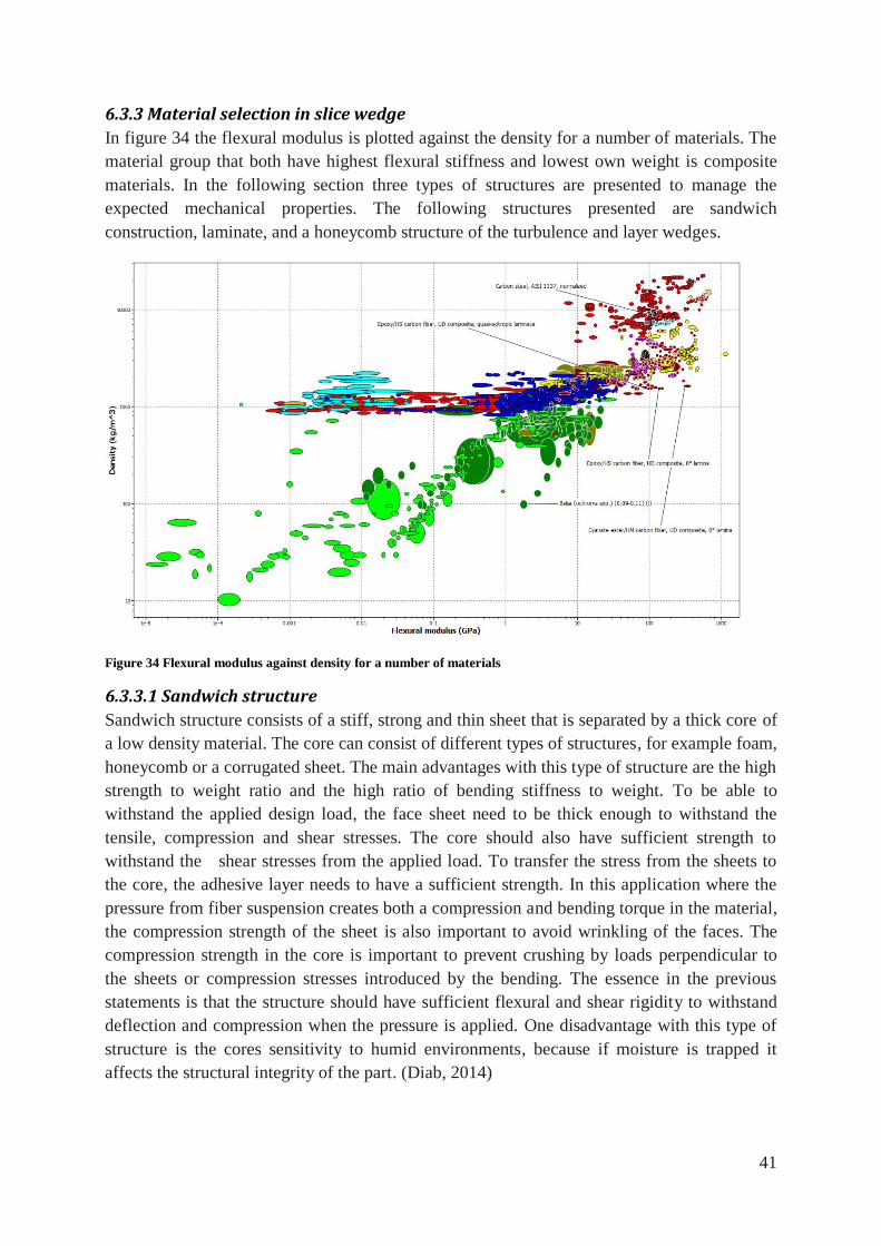
41
6.3.3 Material selection in slice wedge
In figure 34 the flexural modulus is plotted against the density for a number of materials. The
material group that both have highest flexural stiffness and lowest own weight is composite
materials. In the following section three types of structures are presented to manage the
expected mechanical properties. The following structures presented are sandwich
construction, laminate, and a honeycomb structure of the turbulence and layer wedges.
Figure 34 Flexural modulus against density for a number of materials
6.3.3.1 Sandwich structure
Sandwich structure consists of a stiff, strong and thin sheet that is separated by a thick core of
a low density material. The core can consist of different types of structures, for example foam,
honeycomb or a corrugated sheet. The main advantages with this type of structure are the high
strength to weight ratio and the high ratio of bending stiffness to weight. To be able to
withstand the applied design load, the face sheet need to be thick enough to withstand the
tensile, compression and shear stresses. The core should also have sufficient strength to
withstand the shear stresses from the applied load. To transfer the stress from the sheets to
the core, the adhesive layer needs to have a sufficient strength. In this application where the
pressure from fiber suspension creates both a compression and bending torque in the material,
the compression strength of the sheet is also important to avoid wrinkling of the faces. The
compression strength in the core is important to prevent crushing by loads perpendicular to
the sheets or compression stresses introduced by the bending. The essence in the previous
statements is that the structure should have sufficient flexural and shear rigidity to withstand
deflection and compression when the pressure is applied. One disadvantage with this type of
structure is the cores sensitivity to humid environments, because if moisture is trapped it
affects the structural integrity of the part. (Diab, 2014)
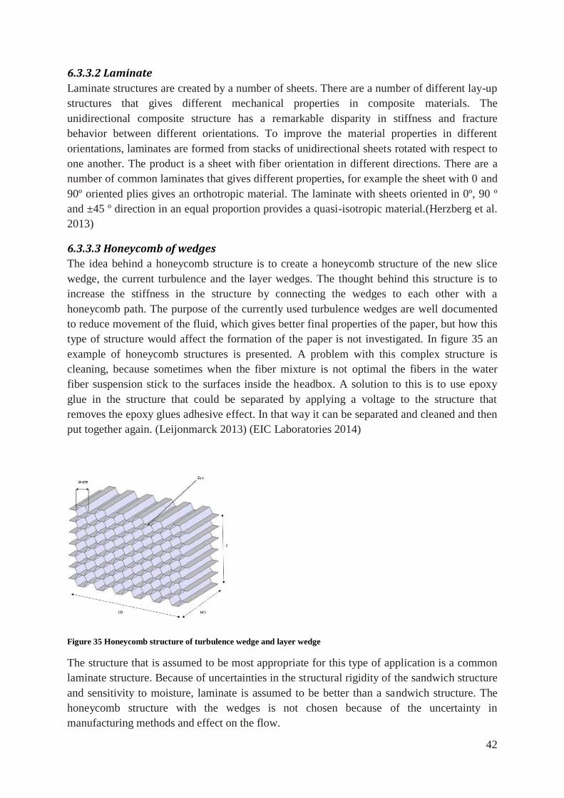
42
6.3.3.2 Laminate
Laminate structures are created by a number of sheets. There are a number of different lay-up
structures that gives different mechanical properties in composite materials. The
unidirectional composite structure has a remarkable disparity in stiffness and fracture
behavior between different orientations. To improve the material properties in different
orientations, laminates are formed from stacks of unidirectional sheets rotated with respect to
one another. The product is a sheet with fiber orientation in different directions. There are a
number of common laminates that gives different properties, for example the sheet with 0 and
90º oriented plies gives an orthotropic material. The laminate with sheets oriented in 0º, 90 º
and ±45 º direction in an equal proportion provides a quasi-isotropic material.(Herzberg et al.
2013)
6.3.3.3 Honeycomb of wedges
The idea behind a honeycomb structure is to create a honeycomb structure of the new slice
wedge, the current turbulence and the layer wedges. The thought behind this structure is to
increase the stiffness in the structure by connecting the wedges to each other with a
honeycomb path. The purpose of the currently used turbulence wedges are well documented
to reduce movement of the fluid, which gives better final properties of the paper, but how this
type of structure would affect the formation of the paper is not investigated. In figure 35 an
example of honeycomb structures is presented. A problem with this complex structure is
cleaning, because sometimes when the fiber mixture is not optimal the fibers in the water
fiber suspension stick to the surfaces inside the headbox. A solution to this is to use epoxy
glue in the structure that could be separated by applying a voltage to the structure that
removes the epoxy glues adhesive effect. In that way it can be separated and cleaned and then
put together again. (Leijonmarck 2013) (EIC Laboratories 2014)
Figure 35 Honeycomb structure of turbulence wedge and layer wedge
The structure that is assumed to be most appropriate for this type of application is a common
laminate structure. Because of uncertainties in the structural rigidity of the sandwich structure
and sensitivity to moisture, laminate is assumed to be better than a sandwich structure. The
honeycomb structure with the wedges is not chosen because of the uncertainty in
manufacturing methods and effect on the flow.
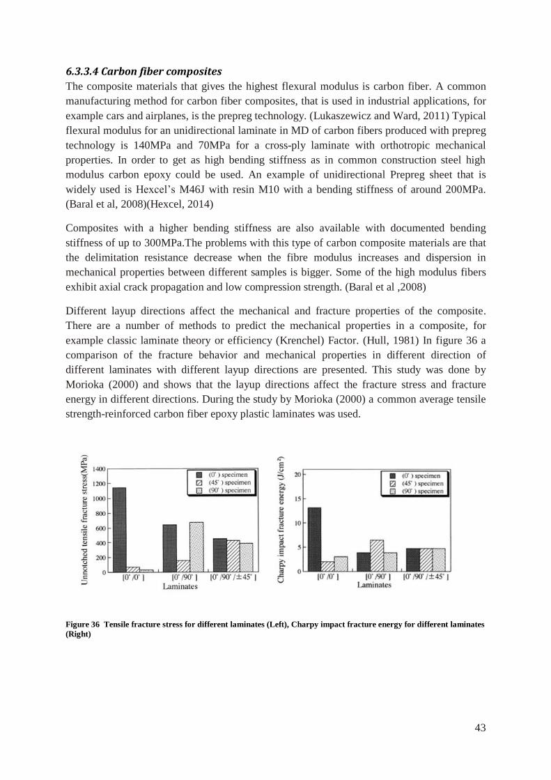
43
6.3.3.4 Carbon fiber composites
The composite materials that gives the highest flexural modulus is carbon fiber. A common
manufacturing method for carbon fiber composites, that is used in industrial applications, for
example cars and airplanes, is the prepreg technology. (Lukaszewicz and Ward, 2011) Typical
flexural modulus for an unidirectional laminate in MD of carbon fibers produced with prepreg
technology is 140MPa and 70MPa for a cross-ply laminate with orthotropic mechanical
properties. In order to get as high bending stiffness as in common construction steel high
modulus carbon epoxy could be used. An example of unidirectional Prepreg sheet that is
widely used is Hexcel’s M46J with resin M10 with a bending stiffness of around 200MPa.
(Baral et al, 2008)(Hexcel, 2014)
Composites with a higher bending stiffness are also available with documented bending
stiffness of up to 300MPa.The problems with this type of carbon composite materials are that
the delimitation resistance decrease when the fibre modulus increases and dispersion in
mechanical properties between different samples is bigger. Some of the high modulus fibers
exhibit axial crack propagation and low compression strength. (Baral et al ,2008)
Different layup directions affect the mechanical and fracture properties of the composite.
There are a number of methods to predict the mechanical properties in a composite, for
example classic laminate theory or efficiency (Krenchel) Factor. (Hull, 1981) In figure 36 a
comparison of the fracture behavior and mechanical properties in different direction of
different laminates with different layup directions are presented. This study was done by
Morioka (2000) and shows that the layup directions affect the fracture stress and fracture
energy in different directions. During the study by Morioka (2000) a common average tensile
strength-reinforced carbon fiber epoxy plastic laminates was used.
Figure 36 Tensile fracture stress for different laminates (Left), Charpy impact fracture energy for different laminates
(Right)
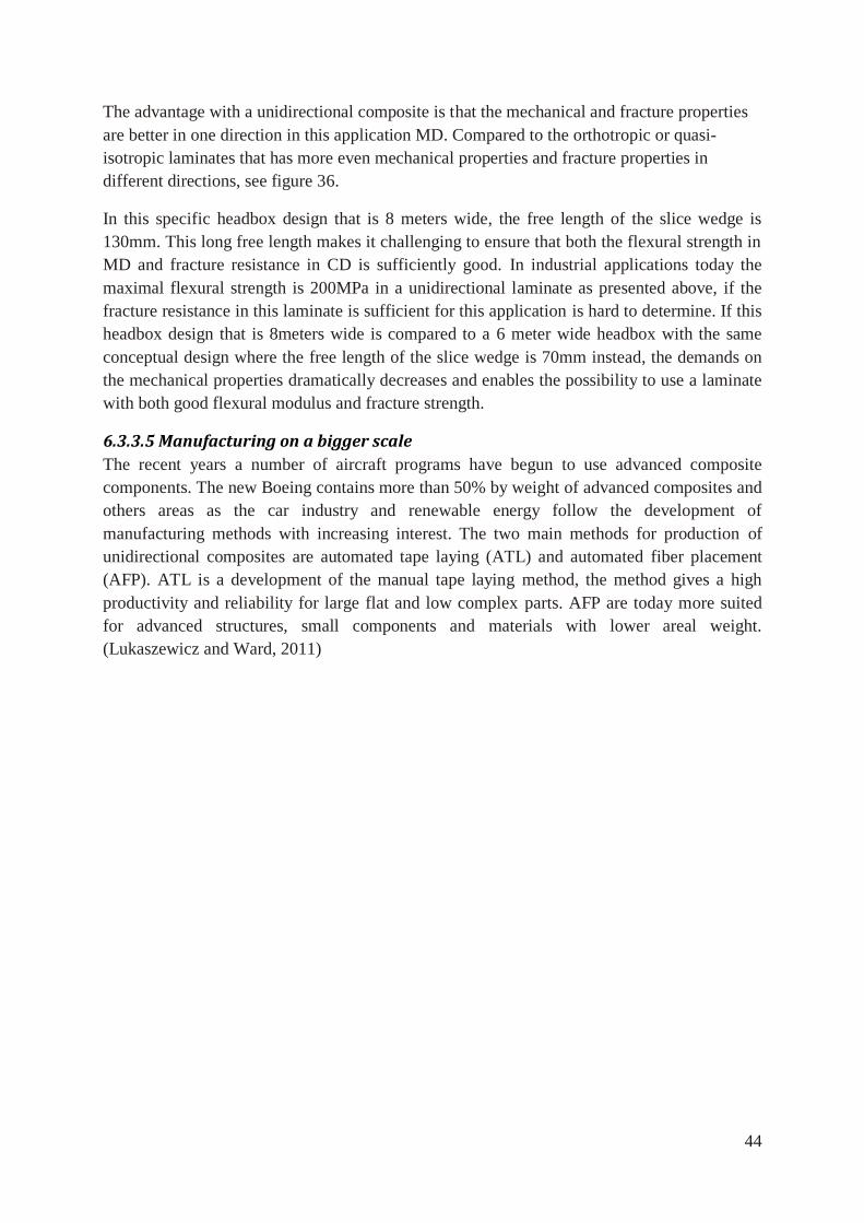
44
The advantage with a unidirectional composite is that the mechanical and fracture properties
are better in one direction in this application MD. Compared to the orthotropic or quasi-
isotropic laminates that has more even mechanical properties and fracture properties in
different directions, see figure 36.
In this specific headbox design that is 8 meters wide, the free length of the slice wedge is
130mm. This long free length makes it challenging to ensure that both the flexural strength in
MD and fracture resistance in CD is sufficiently good. In industrial applications today the
maximal flexural strength is 200MPa in a unidirectional laminate as presented above, if the
fracture resistance in this laminate is sufficient for this application is hard to determine. If this
headbox design that is 8meters wide is compared to a 6 meter wide headbox with the same
conceptual design where the free length of the slice wedge is 70mm instead, the demands on
the mechanical properties dramatically decreases and enables the possibility to use a laminate
with both good flexural modulus and fracture strength.
6.3.3.5 Manufacturing on a bigger scale
The recent years a number of aircraft programs have begun to use advanced composite
components. The new Boeing contains more than 50% by weight of advanced composites and
others areas as the car industry and renewable energy follow the development of
manufacturing methods with increasing interest. The two main methods for production of
unidirectional composites are automated tape laying (ATL) and automated fiber placement
(AFP). ATL is a development of the manual tape laying method, the method gives a high
productivity and reliability for large flat and low complex parts. AFP are today more suited
for advanced structures, small components and materials with lower areal weight.
(Lukaszewicz and Ward, 2011)
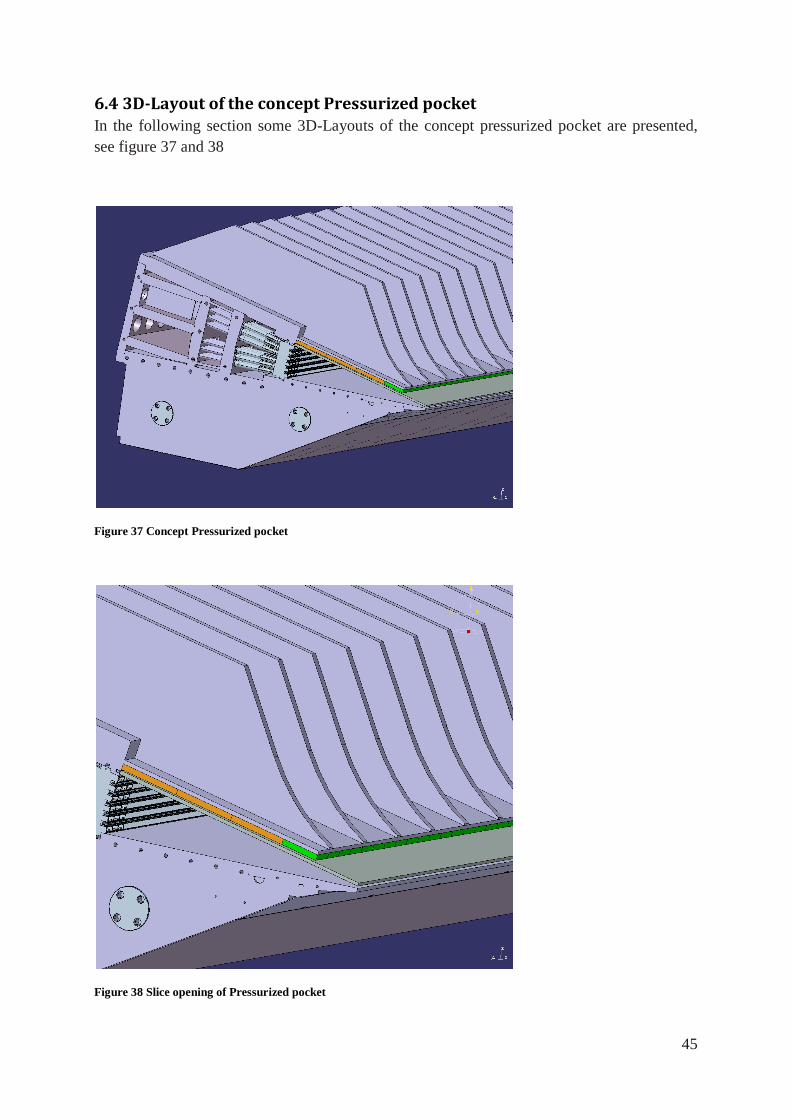
45
6.4 3D-Layout of the concept Pressurized pocket In the following section some 3D-Layouts of the concept pressurized pocket are presented,
see figure 37 and 38
Figure 37 Concept Pressurized pocket
Figure 38 Slice opening of Pressurized pocket
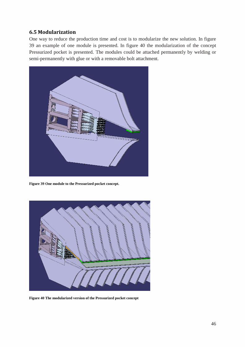
46
6.5 Modularization One way to reduce the production time and cost is to modularize the new solution. In figure
39 an example of one module is presented. In figure 40 the modularization of the concept
Pressurized pocket is presented. The modules could be attached permanently by welding or
semi-permanently with glue or with a removable bolt attachment.
Figure 39 One module to the Pressurized pocket concept.
Figure 40 The modularized version of the Pressurized pocket concept
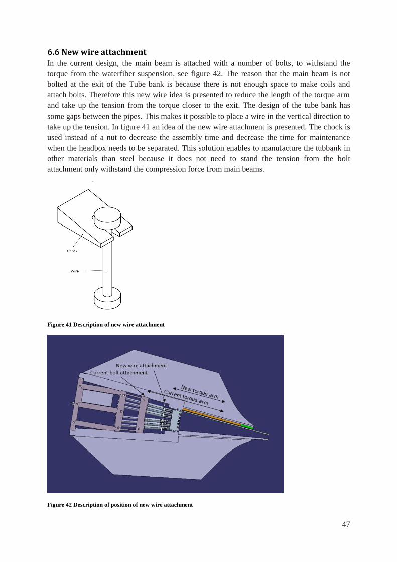
47
6.6 New wire attachment In the current design, the main beam is attached with a number of bolts, to withstand the
torque from the waterfiber suspension, see figure 42. The reason that the main beam is not
bolted at the exit of the Tube bank is because there is not enough space to make coils and
attach bolts. Therefore this new wire idea is presented to reduce the length of the torque arm
and take up the tension from the torque closer to the exit. The design of the tube bank has
some gaps between the pipes. This makes it possible to place a wire in the vertical direction to
take up the tension. In figure 41 an idea of the new wire attachment is presented. The chock is
used instead of a nut to decrease the assembly time and decrease the time for maintenance
when the headbox needs to be separated. This solution enables to manufacture the tubbank in
other materials than steel because it does not need to stand the tension from the bolt
attachment only withstand the compression force from main beams.
Figure 41 Description of new wire attachment
Figure 42 Description of position of new wire attachment
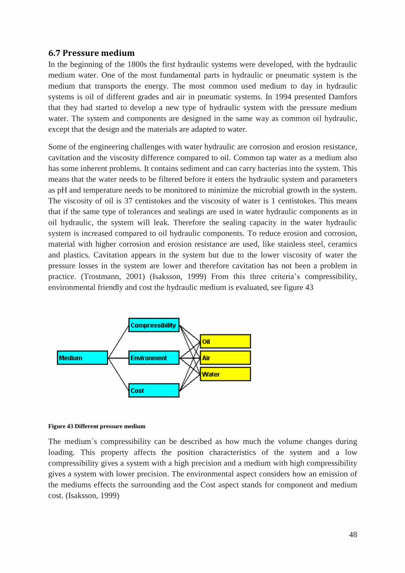
48
6.7 Pressure medium In the beginning of the 1800s the first hydraulic systems were developed, with the hydraulic
medium water. One of the most fundamental parts in hydraulic or pneumatic system is the
medium that transports the energy. The most common used medium to day in hydraulic
systems is oil of different grades and air in pneumatic systems. In 1994 presented Damfors
that they had started to develop a new type of hydraulic system with the pressure medium
water. The system and components are designed in the same way as common oil hydraulic,
except that the design and the materials are adapted to water.
Some of the engineering challenges with water hydraulic are corrosion and erosion resistance,
cavitation and the viscosity difference compared to oil. Common tap water as a medium also
has some inherent problems. It contains sediment and can carry bacterias into the system. This
means that the water needs to be filtered before it enters the hydraulic system and parameters
as pH and temperature needs to be monitored to minimize the microbial growth in the system.
The viscosity of oil is 37 centistokes and the viscosity of water is 1 centistokes. This means
that if the same type of tolerances and sealings are used in water hydraulic components as in
oil hydraulic, the system will leak. Therefore the sealing capacity in the water hydraulic
system is increased compared to oil hydraulic components. To reduce erosion and corrosion,
material with higher corrosion and erosion resistance are used, like stainless steel, ceramics
and plastics. Cavitation appears in the system but due to the lower viscosity of water the
pressure losses in the system are lower and therefore cavitation has not been a problem in
practice. (Trostmann, 2001) (Isaksson, 1999) From this three criteria’s compressibility,
environmental friendly and cost the hydraulic medium is evaluated, see figure 43
Figure 43 Different pressure medium
The medium´s compressibility can be described as how much the volume changes during
loading. This property affects the position characteristics of the system and a low
compressibility gives a system with a high precision and a medium with high compressibility
gives a system with lower precision. The environmental aspect considers how an emission of
the mediums effects the surrounding and the Cost aspect stands for component and medium
cost. (Isaksson, 1999)
49
The difference between the fluids and the gas is that air is more compressible than oil and
water, which reduce the precision. If the mediums are compared from an environmental point
of view, the environmental effect of pollution from oil is far more severe than pollution from
water or air. The pressure medium water, that is used in hydraulic, commonly contains
additives that increase the bio degradation to around 24hours. From an economical point of
view, oil is the most expensive medium; water is around 50 000 times cheaper than oil. The
component cost for a water hydraulic system is around 20% more expensive compared to oil
hydraulic system. (Trostmann, 2001)
50
6.8 Design of the hydraulic system The current paper machine always has an oil hydraulic system installed. The hydraulic system
is used both in operation and maintenance condition for position adjustment, lubrication and
dewatering of paper with pressure. The design of the hydraulic system is based on the current
oil hydraulic system. To adjust the concept pressurized pocket, which includes a number of
pockets the following components are necessary
Work station
Electrical steering to valves
Piping
The following components needed to be included to adjust one pocket
Pressure relief valve
Two directional valves
Proportional directional valve, direct operated with pq function
External pressure sensor
Piping
The proportional direction valve is the main component in the design, which is controlled
with the electrical steering and the workstation. Pressure relief valve is used to reduce the
system pressure to around 10bar and the two directional valves are used to disconnect the
pockets for maintenance. To increase the accuracy and safety, an external pressure sensor is
also included.
6.9 Economical comparison The total cost of the concept pressurized pocket is 5% higher than the current solution.
Calculations and estimations will not be presented because the cost on every component is
confidential information.
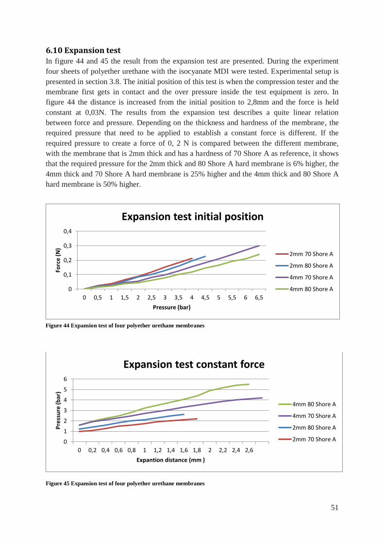
51
6.10 Expansion test In figure 44 and 45 the result from the expansion test are presented. During the experiment
four sheets of polyether urethane with the isocyanate MDI were tested. Experimental setup is
presented in section 3.8. The initial position of this test is when the compression tester and the
membrane first gets in contact and the over pressure inside the test equipment is zero. In
figure 44 the distance is increased from the initial position to 2,8mm and the force is held
constant at 0,03N. The results from the expansion test describes a quite linear relation
between force and pressure. Depending on the thickness and hardness of the membrane, the
required pressure that need to be applied to establish a constant force is different. If the
required pressure to create a force of 0, 2 N is compared between the different membrane,
with the membrane that is 2mm thick and has a hardness of 70 Shore A as reference, it shows
that the required pressure for the 2mm thick and 80 Shore A hard membrane is 6% higher, the
4mm thick and 70 Shore A hard membrane is 25% higher and the 4mm thick and 80 Shore A
hard membrane is 50% higher.
Figure 45 Expansion test of four polyether urethane membranes
0
1
2
3
4
5
6
0 0,2 0,4 0,6 0,8 1 1,2 1,4 1,6 1,8 2 2,2 2,4 2,6
Pre
ssu
re (
bar
)
Expantion distance (mm )
Expansion test constant force
4mm 80 Shore A
4mm 70 Shore A
2mm 80 Shore A
2mm 70 Shore A
0
0,1
0,2
0,3
0,4
0 0,5 1 1,5 2 2,5 3 3,5 4 4,5 5 5,5 6 6,5
Forc
e (
N)
Pressure (bar)
Expansion test initial position
2mm 70 Shore A
2mm 80 Shore A
4mm 70 Shore A
4mm 80 Shore A
Figure 44 Expansion test of four polyether urethane membranes
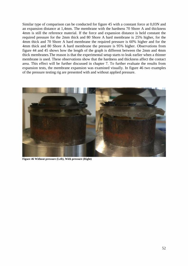
52
Similar type of comparison can be conducted for figure 45 with a constant force at 0,03N and
an expansion distance at 1,4mm. The membrane with the hardness 70 Shore A and thickness
4mm is still the reference material. If the force and expansion distance is held constant the
required pressure for the 2mm thick and 80 Shore A hard membrane is 25% higher, for the
4mm thick and 70 Shore A hard membrane the required pressure is 60% higher and for the
4mm thick and 80 Shore A hard membrane the pressure is 95% higher. Observations from
figure 44 and 45 shows how the length of the graph is different between the 2mm and 4mm
thick membranes.The reason is that the experimental setup starts to leak earlier when a thinner
membrane is used. These observations show that the hardness and thickness affect the contact
area. This effect will be further discussed in chapter 7. To further evaluate the results from
expansion tests, the membrane expansion was examined visually. In figure 46 two examples
of the pressure testing rig are presented with and without applied pressure.
Figure 46 Without pressure (Left), With pressure (Right)
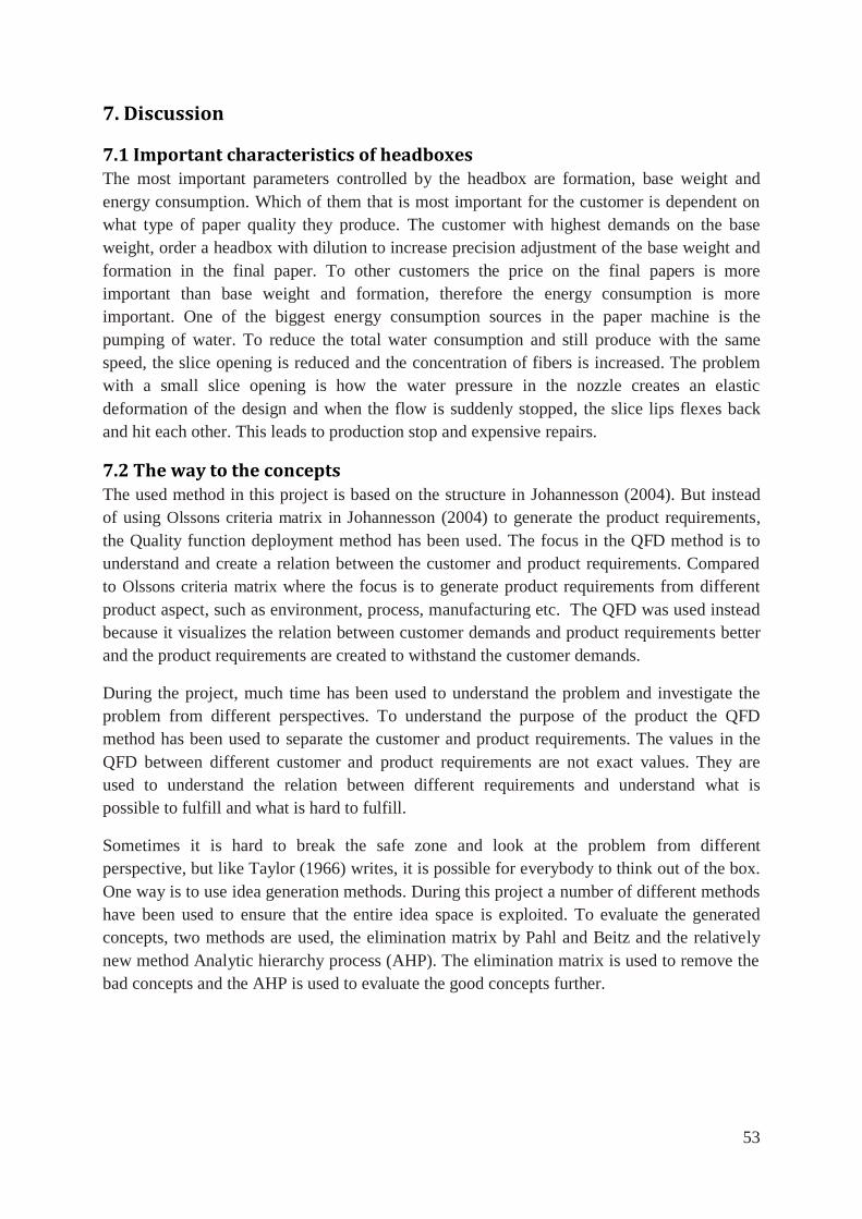
53
7. Discussion
7.1 Important characteristics of headboxes The most important parameters controlled by the headbox are formation, base weight and
energy consumption. Which of them that is most important for the customer is dependent on
what type of paper quality they produce. The customer with highest demands on the base
weight, order a headbox with dilution to increase precision adjustment of the base weight and
formation in the final paper. To other customers the price on the final papers is more
important than base weight and formation, therefore the energy consumption is more
important. One of the biggest energy consumption sources in the paper machine is the
pumping of water. To reduce the total water consumption and still produce with the same
speed, the slice opening is reduced and the concentration of fibers is increased. The problem
with a small slice opening is how the water pressure in the nozzle creates an elastic
deformation of the design and when the flow is suddenly stopped, the slice lips flexes back
and hit each other. This leads to production stop and expensive repairs.
7.2 The way to the concepts The used method in this project is based on the structure in Johannesson (2004). But instead
of using Olssons criteria matrix in Johannesson (2004) to generate the product requirements,
the Quality function deployment method has been used. The focus in the QFD method is to
understand and create a relation between the customer and product requirements. Compared
to Olssons criteria matrix where the focus is to generate product requirements from different
product aspect, such as environment, process, manufacturing etc. The QFD was used instead
because it visualizes the relation between customer demands and product requirements better
and the product requirements are created to withstand the customer demands.
During the project, much time has been used to understand the problem and investigate the
problem from different perspectives. To understand the purpose of the product the QFD
method has been used to separate the customer and product requirements. The values in the
QFD between different customer and product requirements are not exact values. They are
used to understand the relation between different requirements and understand what is
possible to fulfill and what is hard to fulfill.
Sometimes it is hard to break the safe zone and look at the problem from different
perspective, but like Taylor (1966) writes, it is possible for everybody to think out of the box.
One way is to use idea generation methods. During this project a number of different methods
have been used to ensure that the entire idea space is exploited. To evaluate the generated
concepts, two methods are used, the elimination matrix by Pahl and Beitz and the relatively
new method Analytic hierarchy process (AHP). The elimination matrix is used to remove the
bad concepts and the AHP is used to evaluate the good concepts further.
54
One of the biggest problems with decision making is to visualize the decision patterns and
understand how some decisions affect the final results more. This is one of the advantages
with AHP, it is possible to evaluate how consistent your decisions are and how it affects the
final decision. The reason AHP was used instead of the decision matrix presented in
Johanesson (2004) is that AHP visualizes the decision pattern in another way and it is possible
to measure the inconsistency in the decisions. The biggest disadvantage with this method is
the complex mathematic it is based on. I believe this is the largest reason this method is not
used in a larger extent. However I think this type of method will be more important because
of the transparency in decision making becomes more and more important to justify the
decision.
7.3 Discussion of simulation of apron beam The results from the simulation of the apron beam shows that it is possible to reach the same
elastic deformation in the modified design as in the current design. If the thickness is
increased in the stiffeners and the stiffness in the arms is improved, the elastic deformation in
the lip is almost equal in the modified and the current design. If the total elastic deflection in
the lip is compared between the current version and the modified version, with the same
thickness in the stiffeners and same arms, the total difference in elastic deformation in the
nozzle is 7%. If instead the current design is compared to the modified version with 40mm
stiffeners, the difference in total deflection is 3%. If the stiffness in the arms also is improved
the total difference in deflection is 1, 6%. The modified design where 45mm thick stiffeners
were used is not included in the comparison because the delivery time for the 45mm thick
stiffeners is too long. To determine if the modifications should be implemented or not an
economical comparison was conducted. The result from the economical comparison showed
that independent on which one of the modifications that will be implemented, it would not
increase the cost of the headbox with more than 0,3%. Depending on the flow velocity, the
desired stiffness in the headbox is adapted, to withstand the demand on elastic deformation.
Therefore the implementation of the modification depends on how important the deflection is
for the customer, and how many design variations that are acceptable between the different
headbox models.
7.4 Discussion of pressurized pocket The other chosen concept from the analytic hierarchy process was the concept pressurized
pocket. This concept is an innovative concept that changes the whole design of the headbox.
It is assumed to give higher precision in the adjustment of the base weight. Much focus during
the design of this new headbox layout has therefore been focused on describing the new
components and motivate the chosen materials and structures. One of the biggest advantages
besides the increased adjustment possibilities of the base weight and formation is the
possibility to modularize the headbox and reduce the production cost and increase the
standardization of the headbox.
Besides from the new ground idea with the pressurized pockets that adjust the base weight,
this new solution contains some additional new solutions. The first one that is presented in
this report is a honeycomb structure to increase the stiffness in the free length of the Slice
wedge. An additional effect of this honeycomb structure is the effect on the flow. The first
55
thought with this concept was that it would affect the flow in a negative way. But after further
reflection the new type of structure could increase the uniformity of the fibre orientation in the
CD of the paper. Because as Aidun and Kovacs (1995) proposed, the uniformity of the fibre
orientation is reduced by secondary flow created on the surface inside the Headbox nozzle.
This new solution could restrict the movement in CD and increase the quality of the paper.
The other new idea is about how the main beams can be mounted on to the tube bank, to
decrease the torque arm from the waterfiber suspension. In chapter 6.6 is the new wire
attachment is presented and compared to the current bolt attachment. This new solution is
assumed to decrease the assembly time and enable a production of the complex tube bank in
another material than stainless steel, since the requirement of thread in the tube bank was
removed. This means that the tube bank could be produced in another material. One possible
manufacturing method for the tube bank could be 3D printing in a polymer material.
From the mechanical analysis of the pressurized pocket and the current apron beam the
following comparison can be made. If the force in the guide is compared between the current
apron beam and the concept pressurized pocket, it shows that the force in the guide in the
pressurized pocket in the MD direction is much lower, 0,01N/mm compared to 35,3N/mm in
the current design. This shows how the main design can be changed to avoid unnecessary
internal forces, instead of solving the problem later and sub optimize the design.
One of the new components in this concept is the expanding pockets which are expanded by
applying a pressure inside the pockets. The design of the pockets is evaluated with some
simple schematic elongation calculations. It shows that the quadratic cross section utilize the
material in a more effective way and is therefore in this type of design preferable compared to
a circular cross section. The material that withstands the demands on elongation and
withstand s the humid environment is a polyether urethane with the isocynate MDI. To further
develop the pressurized pocket, a new innovative experimental setup was conducted. During
the experiment, four material sheets were tested with different thickness and hardness. The
material that is used in the pocket is a polyurethane material and the main design criteria for
the pockets are high elongation, but the Young’s modulus and the thickness of the sheets are
also important. The relation between the hardness and young’s modulus is really strong;
therefore the strength of an elastomer is sometimes described with hardness. Depending on
the thickness and hardness, different amount of energy is used to expand the membrane. The
contact area is also affected by the hardness and the thickness of the sheet. To better
understand the expansion, an ocular observation was conducted. It shows that the thinner
sheet use a higher contact area than the thicker sheet to transfer the same force. This
observation is illustrated with figure 47, but the observations are done at a limited
experimental result. To be able to create a relation between the parameters pressure in
medium, contact pressure, membrane thickness, membrane hardness and size of pocket, the
extent of the test needs to be increased. During the experiment, the possibility to use digital
monitoring of the contact area was investigated but the intended equipment had to low
resolution to generate useful results.
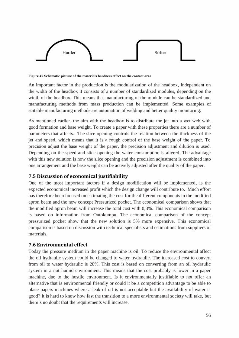
56
Figure 47 Schematic picture of the materials hardness effect on the contact area.
An important factor in the production is the modularization of the headbox, Independent on
the width of the headbox it consists of a number of standardized modules, depending on the
width of the headbox. This means that manufacturing of the module can be standardized and
manufacturing methods from mass production can be implemented. Some examples of
suitable manufacturing methods are automation of welding and better quality monitoring.
As mentioned earlier, the aim with the headbox is to distribute the jet into a wet web with
good formation and base weight. To create a paper with these properties there are a number of
parameters that affects. The slice opening controls the relation between the thickness of the
jet and speed, which means that it is a rough control of the base weight of the paper. To
precision adjust the base weight of the paper, the precision adjustment and dilution is used.
Depending on the speed and slice opening the water consumption is altered. The advantage
with this new solution is how the slice opening and the precision adjustment is combined into
one arrangement and the base weight can be actively adjusted after the quality of the paper.
7.5 Discussion of economical justifiability One of the most important factors if a design modification will be implemented, is the
expected economical increased profit which the design change will contribute to. Much effort
has therefore been focused on estimating the cost for the different components in the modified
apron beam and the new concept Pressurized pocket. The economical comparison shows that
the modified apron beam will increase the total cost with 0,3%. This economical comparison
is based on information from Outokumpu. The economical comparison of the concept
pressurized pocket show that the new solution is 5% more expensive. This economical
comparison is based on discussion with technical specialists and estimations from suppliers of
materials.
7.6 Environmental effect Today the pressure medium in the paper machine is oil. To reduce the environmental affect
the oil hydraulic system could be changed to water hydraulic. The increased cost to convert
from oil to water hydraulic is 20%. This cost is based on converting from an oil hydraulic
system in a not humid environment. This means that the cost probably is lower in a paper
machine, due to the hostile environment. Is it environmentally justifiable to not offer an
alternative that is environmental friendly or could it be a competition advantage to be able to
place papers machines where a leak of oil is not acceptable but the availability of water is
good? It is hard to know how fast the transition to a more environmental society will take, but
there’s no doubt that the requirements will increase.
57
7.7 Future work and suggestions for future research This project is based on the fact that the process parameter jet length should be less than
200mm. The reason is that the quality of the paper has been documented to decrease if the jet
length is over 200mm. In section 2.5 a scientific investigation of headboxes is presented,
Nordström (2003) and Ullmar (1998) presented a relation between anisotropy in the paper and
contraction ratio, but the relation between jet length and contraction ratio of the nozzle has not
be evaluated, is there a relation between them and how is the quality of the paper affected?
In the beginning of the project a literature study was conducted to understand the purpose of
the headbox. Much effort the latest year has been focused on understanding the effect of the
surface inside the headbox and its effect on the flow. From this perspective it would be
interesting to investigate how the surface roughness of different materials affect the flow. For
example could the headbox be coated at the inside to decrease the effect on the flow from the
zone closest to the walls.
To evaluate the design of the pockets and slice wedge further by including experts at
manufacturing of polyurethane and carbon fiber composites, would also have been
interesting?
8. Concluding remarks
The current apron beam is possible to modify to withstand the demand on elastic
deformation and fit in an 8 meter wide paper machine.
Which one of the modifications of the apron beam that will be implemented depend on
how much the design of the 8meter wide headbox can differ from the other headbox
widths.
The increased cost for the modification apron beam is small in the context.
The new headbox design Pressurized pocket is a concept that gives increased
possibility to adjust the base weight and allows an active adjustment of the slice
opening depending on the actual paper quality.
If the new headbox concept Pressurized pocket would be implemented it would enable
modularization and further development of the headbox.
58
9. References Aidun, C. K. Kovacs, A. E. (1995) Hydrodynamics of the forming section: the
origin of nonuniform fiber orientation. Tappi J. 78 (11), 97–106.
Andritz paper (2009). Prime Flow headbox: For superior tissue quality. Avaiable:
http://www.flowtec.at/var/ezwebin_site/storage/original/application/956b27c962a1c99a486fb
1c59c1d9977.pdf Accessed: 7 mars 2014
Baral, N. Davies, P. Baley, C. Bigourdan, B. (2008) Delamination behaviour of very high
modulus carbon/epoxy marine composites Composites Science and Technology 68, 995–1007
Carlsson, A. Söderberg, D. Lundell, F. (2009) Fibre orientation near a wall of a headbox
Nordic Pulp & Paper Research Journal 25, 204-212.
Creativity Web (2014). Available at: http://members.optusnet.com.au/charles57/Creative/
index2.html Accessed 15 February 2014
Diab (2014). Sandwish handbook Available at: http://www.carmas.com.ar/
DOWN/DIVINYCELL/HBook.pdf Accessed. 25 april 2014
EIC Laboratories 2014, ElectRelease™ E4 data sheet. Available http://www.eiclabs.com
/ElectRelease_E4_06-09-00.pdf Accessed. 2014-05-10
Gustafsson, A. (1998). QFD Vägen till nöjdare kunder I teori och praktik Lund: Student
litteratur
Holm, R. & Söderberg, D. (2007). Shear influence on fibre orientation. Rheol. Acta
46, 721–729.
Hexcel (2014). HexPly Prepreg Technology Avaible at http://www.hexcel.com/
Resources/DataSheets/Brochure-Data-Sheets/Prepreg_Technology.pdf. Accessed 15april
2014
Hertzberg, R.W. Vinci, R.P. Hertzberg, J.L. (2013). Deformation and Fracture Mechanics of
Engineering Materials. New York. Fifth edition John Wiley and Sons
Hull, D. (1981). An introduction to composite materials. Cambrige: Cambridge University
Press
Hyensjö, M. (2008). Fibre Orientation Modelling Applied to Contracting Flows Related to
Papermaking. Doctoral Thesis from Royal Institute of Technology
Isaksson, O. (1999). Grundläggande hydraulik Luleå: Luleå Tekniska Universitet
Johannesson, H. (2004). Produktutveckling-effektiva metoder för konstruktion och
design.First Edition, Malmö:Liber.
Ulrich K.T, Eppinger S. E. (2008). Product Design and Development. Firth edition New
York: McGraw Hill.
59
Leijonmarck, S. (2013). Preparation and Characterization of Electrochemical Devices for
Energy Storage and Debonding. Doctoral Thesis from Royal Institute of Technology
Liu, G. R. (2003). Finite element method: a practical course. Oxford: Butterworth-
Heinemann.
Lukaszewicz, D. Carwayn, W. (2012). The enginnering aspects of automated prepreg layoup:
History present and future. Composites: Part B 43, 997-1009
Mann, S.H (1995). Using The Anlytic Hierachy Process for decision making in engineering
applications: Some challenges Interl Journal of Industrial Engineering Applications and
Practice. 2(1) pp35-44
Morioka, K. Yoshiyuki, T. (1997). Effect of lay-up sequences on mechanical properties and
fracture behavior of CFRP laminate composites. Materials Characterization 45 (2000) 125-
136
Nordström, B. (2003a). Effects of headbox tube design and flow rate on formation and other
sheet properties in twin-wire roll forming. Nordic Pulp Paper Res. J.18 (3), 296–302.
Nordström, B. (2003b). Effects of pulp type and headbox design on anisotropy and other
sheet properties in twin-wire forming. Nordic Pulp Paper Res. J. 18 (3), 288–295.
Olson, J. (2002). Analytic estimate of the fibre orientation distribution in a headbox
flow. Nordic Pulp Paper Res. J. 17 (3), 302–306.
Outokumpu (2014a). Duplex Stainless Steel: Available at:
http://www.outokumpu.com/SiteCollectionDocuments/Outokumpu-Duplex-Stainless-Steel-
Data-Sheet.pdf. Accessed 25 april 2014
Outokumpu, (2014b). Cost information from Outokumpu on specific components
Sundström, B. (2010) Handbok och formelsamling i Hållfasthetslära. Stockholm: Instant
Book AB Stockholm
Tasowheel (2013). Tasowheel CD Actuators and Valves: for the Paper and Board industry
Available:http://www.tasowheelgroup.fi/wp-content/uploads/2013/11/Tasowheel_products
_for_paper_and_board_industry_2013.pdf Accessed: 10 feb 2014
Taylor J.W. (1966). Hur man skapar nya idéer, Stockholm: K L Beckmans Tryckerier AB,
Ullmar ,M. (1998) On fibre alignment mechanisms in a headbox nozzle. Licentiate thesis,
Royal Institute of Technology, Stockholm, Sweden.
UW-Elast (2005) Materialkunskap: Polyuretan som konstruktionsmaterial. 3: e upplagan
Mariestad:Vadsbo Tryck AB.
Vaidya, O. S. Kumar, S. (2006). Analytic hierarchy process: An overview of applications
European Journal of Operational Research 169, 1–29.

60
Valmet. (2014). Tissue making starts in the headbox OptiFlo II TIS: Available at:
http://www.kawanoe.co.jp/pdf/OptiFlo20091222.pdf. Accessed 15 april, 2014
Voith Paper (2010). A new milestone in headbox development. Available: http://www.voith.
com/en/MasterJet-Pro_Twogether30_ENG.pdf Accessed: 7 mars 2014
Trostmann, E. Frolund, B Olesen, B.H. Hilbrecht B (2001). Tap Water as a Hydraulic
Pressure Medium. New York: Marcel Dekker,inc.
Zhang, X. (1998). Fibre orientation in a headbox. Masters Thesis, The University of British
Columbia, Vancouver.
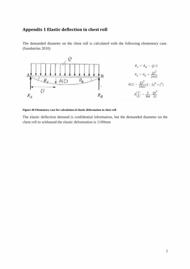
I
Appendix 1 Elastic deflection in chest roll
The demanded diameter on the chest roll is calculated with the following elementary case.
(Sundström 2010)
Figure 48 Elementary case for calculation of elastic deformation in chest roll
The elastic deflection demand is confidential information, but the demanded diameter on the
chest roll to withstand the elastic deformation is 1100mm
II
Appendix 2 Valmet AB and description of a Tissue machine
About Valmet
Valmet is divided in three business lines serving pulp, paper and energy industry. Valmet
focuses on developing and supplying services and technologies, mainly for industries that use
bio-based raw materials. This thesis was conducted at Valmet AB in Karlstad that is a part of
the paper line. Valmets core business in Karlstad is to manufacture and develop new tissue
machines
Tissue machine
The manufacturing process in a tissue machine consists of a number of process steps. It starts
with a wet fiber-water suspension consisting of 98% water that is manufactured to a large
paper roll. One way to divide the tissue machines in two sections is the wet and the dry
section.
Wet section
The first part in the wet section is called the forming section and the main component in this
section is the headbox, which purpose is to distribute the mixture of water and fiber evenly
across the wire. After the headbox, the wire that is permeable is pressed against a roll to be
dewatered and form a wet web. The next step in the wet section is the press section where a
press nip is used to removed more water from the paper. When the paper leaves the press
section it consist of 40-50 percent moisture.
Dry section
The dry section consists of a Yankee cylinder that is a cylinder with a diameter of (∅4-6m)
that is filled with steam, which heats up the lateral surface and dries the paper. To remove the
paper from the cylinder something that is called creeping is used. It is a cutting operation that
gives the paper its final elasticity. When the paper is removed from the Yankee cylinder the
moisture is around 5-10%.
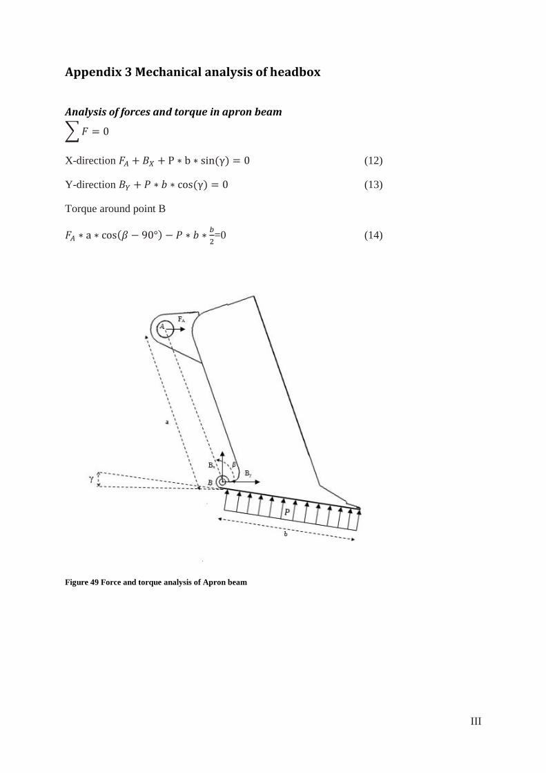
III
Appendix 3 Mechanical analysis of headbox
Analysis of forces and torque in apron beam
∑
X-direction (12)
Y-direction (13)
Torque around point B
=0 (14)
Figure 49 Force and torque analysis of Apron beam
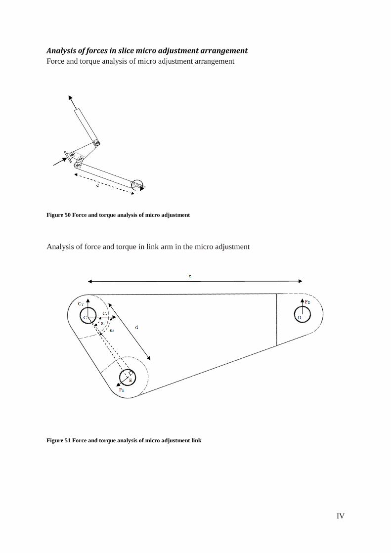
IV
Analysis of forces in slice micro adjustment arrangement
Force and torque analysis of micro adjustment arrangement
Figure 50 Force and torque analysis of micro adjustment
Analysis of force and torque in link arm in the micro adjustment
Figure 51 Force and torque analysis of micro adjustment link
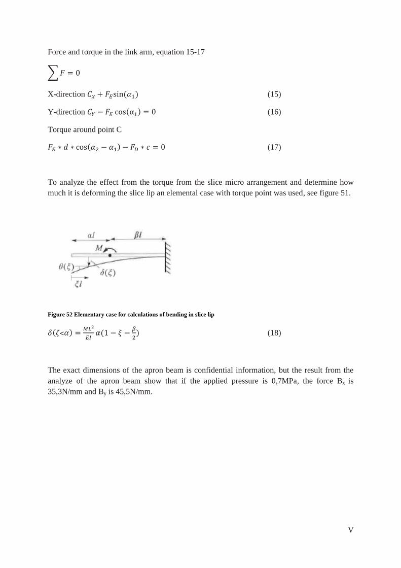
V
Force and torque in the link arm, equation 15-17
∑
X-direction (15)
Y-direction (16)
Torque around point C
(17)
To analyze the effect from the torque from the slice micro arrangement and determine how
much it is deforming the slice lip an elemental case with torque point was used, see figure 51.
Figure 52 Elementary case for calculations of bending in slice lip
(18)
The exact dimensions of the apron beam is confidential information, but the result from the
analyze of the apron beam show that if the applied pressure is 0,7MPa, the force Bx is
35,3N/mm and By is 45,5N/mm.
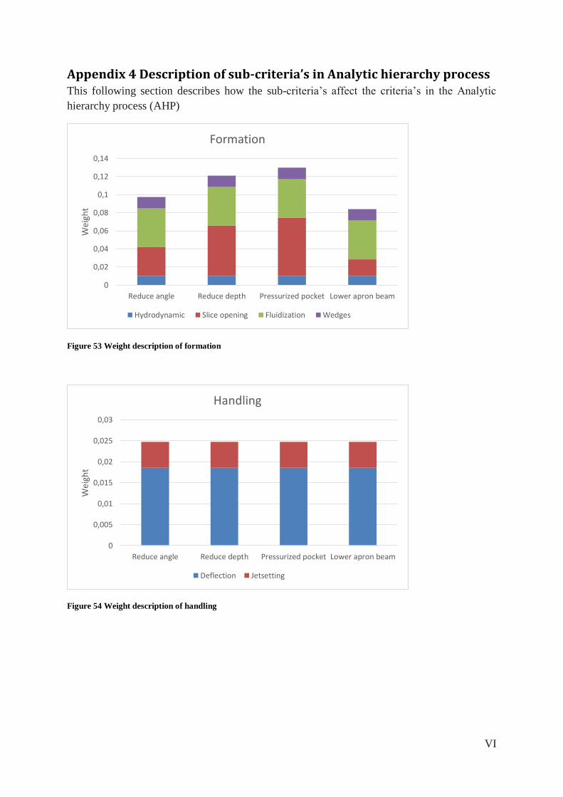
VI
Appendix 4 Description of sub-criteria’s in Analytic hierarchy process This following section describes how the sub-criteria’s affect the criteria’s in the Analytic
hierarchy process (AHP)
Figure 53 Weight description of formation
Figure 54 Weight description of handling
0
0,02
0,04
0,06
0,08
0,1
0,12
0,14
Reduce angle Reduce depth Pressurized pocket Lower apron beam
Wei
ght
Formation
Hydrodynamic Slice opening Fluidization Wedges
0
0,005
0,01
0,015
0,02
0,025
0,03
Reduce angle Reduce depth Pressurized pocket Lower apron beam
Wei
ght
Handling
Deflection Jetsetting
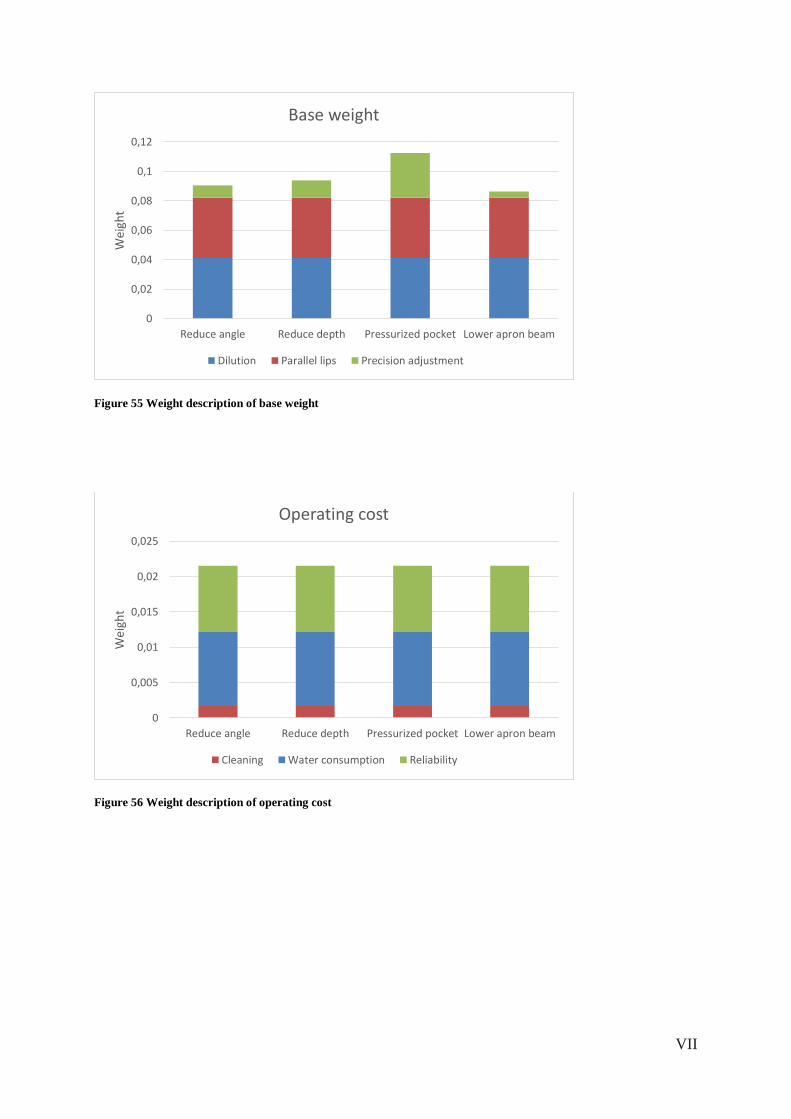
VII
Figure 55 Weight description of base weight
Figure 56 Weight description of operating cost
0
0,02
0,04
0,06
0,08
0,1
0,12
Reduce angle Reduce depth Pressurized pocket Lower apron beam
Wei
ght
Base weight
Dilution Parallel lips Precision adjustment
0
0,005
0,01
0,015
0,02
0,025
Reduce angle Reduce depth Pressurized pocket Lower apron beam
Wei
ght
Operating cost
Cleaning Water consumption Reliability