Embed Size (px)
Citation preview

TM 11-6665-364-12
TECHNICAL MANUAL
OPERATOR’S AND UNITMAINTENANCE MANUAL
RADIAC SET AN/UDR-13(NSN 6665-01-407-1237) (EIC:KYD)
Distribution authorized lo the Department of Defense and DOD contractors onlyfor official use or for administrative or operational purposes. This determinationwas made on 15 June 1995. Other requests for this document must be referredlo Commander, US Army Communications Electronics Command and FortMonmouth. ATTN: AMSEL-LC-LEO-E-ED-P. Fort Monmouth, New Jersey 077035000
DESTRUCTION NOTICE Destroy by any method that will prevent disclosure ofcontents of reconstruction of the document.
HEADQUARTERS, DEPARTMENT OF THE ARMY
1 AUGUST 1998

WARNING
Trichlorotrifluoroethane,trichloroethane and similar chemicalsolvents will no longer be used forordinary cleaning of equipment.These substances threaten publichealth and the environment bydestroying ozone in the earth’s upperatmosphere. Suitable nonhazardouscleaning materials will be usedinstead, such as a clean cloth, waterand mild detergent.
A

HOW TO USE THIS MANUAL
Prior to use or maintenance of the AN/UDR-13,it is recommended that this manual be read inits entirety.
For a description of EquipmentCharacteristics, Capabilities and Featuresrefer to Chapter 1, Section II.
For Equipment Data (weights anddimensions, power requirements,operational ranges, and environmentallimits) refer to Chapter 1, Section II.
For Technical Principals of Operation referto Chapter 1, Section III.
For Operation Under Normal Conditionsrefer to Chapter 2, Section I.
For Operation Under Unusual Conditionsrefer to Chapter 2, Section II.
For Preventative Maintenance Checks andServices (PMCS) refer to Chapter 3,Section II.
For Battery Installation/Removal/Replacement refer to Chapter 3,Section II.
B

HOW TO USE THIS MANUAL (Con’t)
For Preparation For Shipment and/orStorage refer to Chapter 3, Section III.
Familiarize yourself with the informationalso available in the Appendixes A throughG supplied in the rear of this manual.
C/(D Blank)
TM 11-6665-364-12
HEADQUARTERSTechnical Manual DEPARTMENT OF THE ARMYNo. 11-6665-364-2 Washington, DC, 1 August 1998
OPERATOR’S AND UNITMAINTENANCE MANUAL
RADIAC SET AN/UDR-13(NSN 6665-01-407-1237)
(EIC:KYD)
REPORTlNG ERRORS ANDRECOMMENDING IMPROVEMENTS
You can help improve this manual. If you find any mistakes,or if you know of a way to improve the procedures, please letus know, Mail your letter, DA Form 2028 (RecommendedChanges to Publications and Blank Forms) or DA Form2028-2 direct to: Commander, US Army Communications-Electronics Command and Fort Monmouth, ATTN: AMSEL-LC-LEO-D-CS-CFO, Fort Monmouth, New Jersey 07703-5000. The fax number is 732-532-1413, DSN 992-1413.You may also e-mail your recommendationsto AMSEL-LC-LEO-PUBS-CHGBcecom3.monmouth.any.mil
i

TABLE OF CONTENTS
Section I GENERAL INFORMATION
Page
1-11-2
1-3
1-4
1-51-6
1-71-8
1-91-9.1
1-10
1-11
ii
Scope . . . . . . . . . . . . . . . . . 1-1Consolidated Index of ArmyPublications andBlank Forms . . . . . . . . . . . .1-1Maintenance Forms,Records and Reports. . . . . . . . . . . . . . 1-1Destruction of Army ElectronicsMateriel . . . . . . . . . . . . . . . . . 1-2Administrative Storage . . . . . . . . . . . . . . . 1-2Repor t ing Equ ipment 1 -3ImprovementRecommendations (EIR)Quality Assurance (QA) 1-3Official Nomenclature, Namesand Designations. . . . . . . . . . . . . . 1-4Safety, Care and Handling 1-4Nuclear, Biological andChemical (NBC)Decontamination 1-4Corrosion Prevention andControl (CPC). . . . . . . . . . . . . . . . . . . . . 1-5Glossary. . . . . . . . . . . . . . . . . . . . . . 1-6
CHAPTER 1
INTRODUCTION
SECTION II
1-12
1-13
1-14
SECTION Ill
EQUIPMENT DESCRIPTIONAND DATA
Equipment Characteristics,Page
Capabilities and Features 1-7Location and Description ofMajor Components . . . . . . 1-8Equipment Data . . . . 1-9
TECHNICAL PRINCIPALS OFOPERATION . . . . .
CHAPTER 2
1-11
OPERATING INSTRUCTIONS
SECTION I
2-1
2-2
2-3
SECTION II
2-42-5
OPERATION UNDERNORMAL CONDITIONS
Preoperational TestProcedure . . . . . . . . . . .Normal OperatingProcedure . . . . . . . . . . . .Display Light Operation
Battery Life IndicationOperation UnderUnusual Conditions. . . .
2-1
2-92-24
2-24
2-25
iii

CHAPTER 3
OPERATOR AND UNITMAINTENANCE INSTRUCTIONS
PageSECTION I LUBRICATION
INSTRUCTIONS
3-1
SECTION II
L u b r i c a t i o n 3-1
PREVENTATIVEMAINTENANCE CHECKSAND SERVICES (PMCS)
3-23-2.1
3-3
Preventative MaintenanceCleaning, Dusting, andWashing the Set . . . . . . . . . .
3-1
3-2Radiacmeter Battery InstallationRemoval /Replacement 3-2
SECTION Ill PREPARATION FORSTORAGE OR SHIPMENT
3-4 Preparation for Shipment 3-4
3-5 Preparation for Storage . . 3-4
APPENDIXES
A P P E N D I X A R E F E R E N C EAPPENDIX B MAINTENANCEALLOCATION CHART . . . . . . . . .
iv
A-1
B-1

PageSection I introduction . . . . . . . . . . . . . B-1
II Maintenance AllocationChart (MAC) for Radiac SetAN/UDR-13 . . . . . . . . . . . . . B-8
III Tool and Test EquipmentRequirements . . . . . . . . B-9
IV Remarks . . . . . . . . . . . . B-10APPENDIX C
RPSTL (TM 11-6665-364-20P)IS NON-APPLICABLE,EXCEPT FOR CARRYINGCASE CY-8769/UDR-13(SEE PAGE D4)
APPENDIX DCOMPONENTS OF END ITEMAND BASIC ISSUE ITEMSLIST . . . . . . . . . . . . . . D-1
APPENDIX EADDITIONALAUTHORIZATION LIST(Not Applicable)
APPENDIX FEXPENDABLE SUPPLIESAND MATERIALS LIST . . F-1
APPENDIX GSUBJECT INDEX . . . . . . G-1
APPENDIX HCOMMUNICATION(INFRA RED INFO.) . . . H-1(To be supplied at a later date)
v/(vi Blank)
CHAPTER I
INTRODUCTION
SECTION I. GENERAL INFORMATION
1-1. SCOPE
This publication covers operation, unitmaintenance and repair functions required tosupport the AN/UDR-13 Radiac Set.
1-2. CONSOLIDATED INDEX OF ARMYPUBLICATIONS AND BLANK FORMS
Refer to the latest DA Pam 25-30 to determinewhether there are new editions, changes, oradditional publications pertaining to theequipment.
1-3. MAINTENANCE FORMS, RECORDS,AND REPORTS
a. Reports of Maintenance andUnsatisfactory Equipment. Department of theArmy forms and procedures used for equipmentmaintenance will be those prescribed by DAPam 738-750, as contained in MaintenanceManagement Update. Air Force personnel willuse AFR 66-1 for maintenance reporting andTO-00-35D54 for unsatisfactory equipmentreporting. Navy personnel will report
1-1

maintenance performed utilizing theMaintenance Data Collection Subsystem(MDCS) IAW OPNAVINST 4790.2, Vol. 3 andunsatisfactory material/conditions (UR) IAWOPNAVINST 4790.2, Vol.2, Chapter 17.Marine Corps maintains forms and proceduresas prescribed by TM 4700-15/1.
b. Reporting of Item and PackagingDiscrepancies. Fill out and forward SF 364(Report of Discrepancy (ROD)) as prescribed inAR 735-11-2/DLAR 4140.55/SECNAVINST4355,18/AFR 400-54/MCO 4430.3J.
c. Transportation Discrepancy Report(TDR) (SF 361). Fill out and forwardTransportation Discrepancy Report (TDR) (SF361) as prescribed in AR 55-38/NAVSUPINST4610,33C/AFR 75-18/MCO P4610.19D/DLAR4500.15.
1-4. DESTRUCTION OF ARMYELECTRONICS MATERIEL
Destruction of Army electronics materiel toprevent enemy use shall be in accordance withTM 750-244-2.
1-5. ADMINISTRATIVE STORAGE
Administrative storage of equipment issued toand used by Army activities will havePreventative Maintenance Checks and Services(PMCS) performed before storing. When
1-2

removing the equipment from administrativestorage, the PMCS checks should beperformed to assure operational readiness.
1-6. REPORTING EQUIPMENTIMPROVEMENTRECOMMENDATIONS (EIR)
If your equipment needs improvement, let usknow. Send us an EIR. You, the user, are theonly one who can tell us what you don’t likeabout your equipment. Let us know why youdon’t like the design or performance. Put it onan SF 368 (Product Quality Deficiency Report).Mail to: Commander, US ArmyCommunications-Electronics Command andFort Monmouth, ATTN: AMSEL-LC-LEO-D-CS-CFO, Fort Monmouth, New Jersey 07703-5000.We’ll send you a reply.
1-7. QUALITY ASSURANCE (QA)
This equipment has been manufactured andinspected in accordance with MIL-Q-9858A,Quality Program Requirements. Users of thisequipment shall report any quality deficienciesto their supervisor or submit an SF 368(Product Quality Deficiency Report).
1-3

1-8. OFFICIAL NOMENCLATURE, NAMESAND DESIGNATIONS
Nomenclature Cross-Reference.Shortened or modified nomenclature is used inthis manual to make procedures easier for youto read. A cross-reference between shortenedor modified nomenclature and the officialnomenclature is shown in the following table.
ManualNomenclature
Nomenclature Cross-Reference
Radiac SetCase
Official Nomenclature
Radiac Set AN/UDR-13Case, Electrical-Electronics, Test andMeasuring Equipment CY-8769/UDR-13
1-9. SAFETY, CARE AND HANDLING
1-9.1 NUCLEAR, BIOLOGICAL ANDCHEMICAL (NBC)DECONTAMINATIONThe Radiac Set, shall bedecontaminated in accordancewith the appropriate proceduresof Field Manual (FM) 3-5 forNBC Decontamination.
1-4

1-9.2 Refer to Chapter 3, Section IIfor preventative maintenancechecks and services (PMCS).
1-10. CORROSION PREVENTIONAND CONTROL (CPC)
a. Corrosion Prevention and Control(CPC) of the Army material is a continuingconcern. It is important that corrosionproblems with this item be reported so thatthe problem can be corrected andimprovements can be made to prevent theproblem in future items. While corrosion istypically associated with rusting of metals, itcan also include deterioration of othermaterials, such as rubber and plastic.Unusual cracking, softening, swelling orbreaking of these materials may be acorrosion problem.
b. If a corrosion problem is identified, itcan be reported using Standard Form 368.Product Quality Deficiency Report. Use ifkeywords such as “corrosion”, “rust”,“deterioration”, or “cracking” will ensure thatthe information is identified as a CPCproblem. The form should be submitted tothe address specified in DA PAM 738-750Manual.
1-5
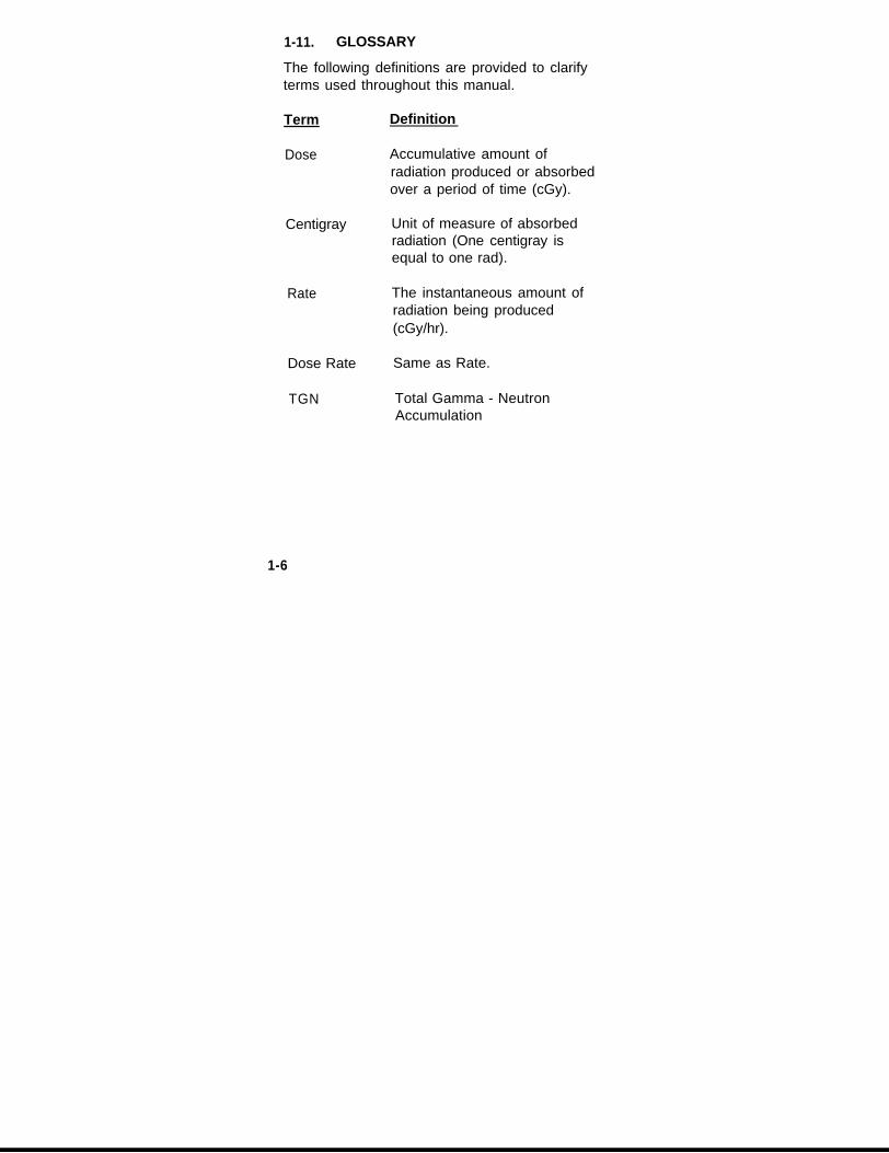
1-11. GLOSSARY
The following definitions are provided to clarifyterms used throughout this manual.
Term
Dose
Centigray
Rate
Dose Rate
TGN
Definition
Accumulative amount ofradiation produced or absorbedover a period of time (cGy).
Unit of measure of absorbedradiation (One centigray isequal to one rad).
The instantaneous amount ofradiation being produced(cGy/hr).
Same as Rate.
Total Gamma - NeutronAccumulation
1-6

SECTION II. EQUIPMENT DESCRIPTIONAND DATA
1-12. EQUIPMENT CHARACTERISTICS,CAPABlLlTlES AND FEATURES
a. The AN/UDR-13 Radiac Set is aportable radiation detector used for detectingNeutron/Gamma radiation dose and Gammadose rate.
b. The AN/UDR-13 Radiac Set consists ofa Radiacmeter and a Case. The Radiacmeteris capable of measuring and displaying 0-999cGy/hr gamma radiation dose rate. TheDosimeter Module is capable of measuring,storing and displaying dose from 0-999 cGy. Italso features a Presettable Alarm and a Sleepmode. The Sleep mode allows for automatic,periodic, short-time displays of dose rate.
c. The Radiac Set is a miniaturizedRadiacmeter that can be carried in a soldierspocket. The set includes a case which is a softcarrying pouch which may be worn on a belt orcarried in a pocket.
1-7

1-13. LOCATION AND DESCRIPTION OFMAJOR COMPONENTS
1-8

1-14. EQUIPMENT DATA
ENVIRONMENTAL
Altitude operating To 15,000 feetrange: (4,572 m) above sea
level
Humidity: 95 percent
Temperature -51 to 120°Foperating range: (-46 to +49°C)
Storage -60 to 160°Ftemperature range: (-52 to +71°C)
Water resistance Will withstandimmersion in water upto 3 feet deep
WEIGHTS AND DIMENSIONS
RADIAC SET Radiacmeter InAlone Carrying
CaseWeight:(with batteries) 9.5 oz. 11.5 oz.
(without batteries) 8.0 oz 10.4 oz.
1-9

1-14. EQUIPMENT DATA (Con't.)
Radiacmeter InAlone Carrying
CaseLength: 3.95” 4.90”
Width: 2.61” 4.00”
Depth: 0.99” 1.90”
POWER 4 (1.5V) AAA dry cellbatteries
BATTERY LIFE
Normal Operation 100 hours
Sleep (SLP) Mode 294 hours
OPERATIONAL: RADIAC SET
Rate
Dose
Accuracy
Communication
0-999 cGy/hr gammaradiation detection
0-999 cGyneutron/gamma doseaccumulation
±20% of True Doseand dose rate
RS-232, via opticallnfra Red data channel
1-10

SECTION III TECHNICAL PRINCIPLES OFOPERATION
1 - 1 1

Gamma rays interact with the GM tube detectorand provide electrical output pulses. Thesepulses are counted by microprocessor (CPU)controlled circuitry and evaluated with respectto reference signals to ultimately provide themeasurement and display of the gamma rayfield intensity in the vicinity of the Radiac Set.The Radiac Set also includes two solid statedetectors for the detection and measurement ofhigh intensity gamma and neutron radiationpulses as encountered when a nuclear weaponis detonated. When these detectors areexposed to such radiation, the detectorexperiences a change of output voltageproportional to the total accumulated dose.This voltage is measured by the internalcircuitry and converted by the microprocessorinto the dose measurement.
1-12

CHAPTER 2OPERATING INSTRUCTIONS
SECTION I. OPERATION UNDERNORMAL CONDITIONS
NOTES: 1.
2.
For simplicitythroughout theseoperating procedures,RATE is used in lieu ofDOSE RATE.Review thePreoperational TestProcedure prior tooperating theAN/UDR-13.
2-1. PREOPERATIONAL TESTPROCEDURE
1. Press and hold ON/OFF button until aseries of indefinite numbers (1-6) will bedisplayed, followed by a full display.
If no display or the letter b is displayed(see page 2-8), in 4 or more seconds,replace batteries (see para. 3-3 (page3-2) in this manual). If there is still nodisplay indication, return entire unitthrough unit level to General Supportfor repairs.
2-1

If DOSE ALARM is flashing seenote on page 2-3.
The following display (RATEMODE) should appear.
ANY OR ALL OF THESE3 INDICATORS MAY NOTBE DISPLAYED DEPENDINGON PREVIOUS USE
a. The radiacmeter must indicateRATE in the top left corner.
b. A reading of .000 must appearfollowed by cGy/hr in knownlow background area.
NOTE:A variable indication above .000 cGy/hrindicates the possible presence ofradiation, notify your supervisor.
2-2
C. The cGy/hr must blinkapproximately every 2 seconds.
If any of these PreoperationalTest Procedures, (except forlow batteries indication), page2-8, are not as described,return entire unit through unitlevel to General Support forrepairs.

NOTE: DOSE FLASHING
If the DOSE ALARM is flashing on unit turn-on,proceed as follows:
a. Check the DOSE total accumulation inaccordance with para. 2-2a2 on page2-11 and retain.
b. Check the DOSE ALARM set point inaccordance with para 2-2c1 on page 2-18 and retain.
c. If the DOSE accumulation is greaterthan the DOSE ALARM set point, theunit is functioning properly - the alarmshould be flashing.
d. This condition can be altered if desired,depending on the mission status, in oneof the following manners,
1) Reset the accumulated dose to000 cGy in accordance withpara. 2-2c3 on page 2-20.
2) Raise the DOSE ALARM setpoint above the DOSEindicated accumulated inaccordance with para. 2-2c2 onpage 2-19.
2-3
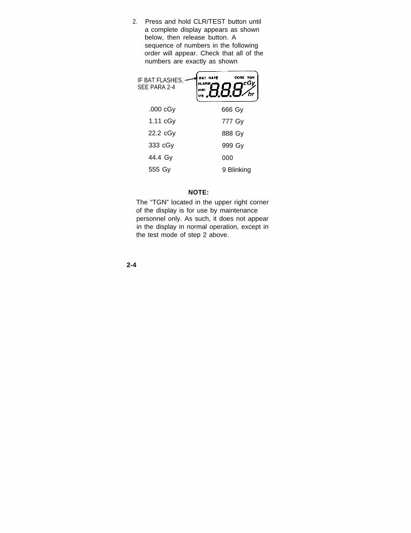
2. Press and hold CLR/TEST button untila complete display appears as shownbelow, then release button. Asequence of numbers in the followingorder will appear. Check that all of thenumbers are exactly as shown
IF BAT FLASHES,SEE PARA 2-4
.000 cGy 666 Gy
1.11 cGy 777 Gy
22.2 cGy 888 Gy
333 cGy 999 Gy
44.4 Gy 000
555 Gy 9 Blinking
NOTE:
The “TGN” located in the upper right cornerof the display is for use by maintenancepersonnel only. As such, it does not appearin the display in normal operation, except inthe test mode of step 2 above.
2-4

NOTE:
A flashing followed in about 10seconds by the blinking 9, indicates that thecombination of the neutron and gammapulse detectors is nearing 1000 cGy of totaldose accumulation. The AN/UDR-13 isentirely functional, including all forms ofdose measurement, and this flashing
is displayed to alert the user that thedosimeter assembly should be replaced inthe near future.
3. At any time during the above sequence ofnumbers, press and hold ALARM button.The alarm should sound and both alarmlights should turn on, press DOSE buttonand only DOSE ALARM LIGHT andsounder turn on, press RATE button onlyRATE ALARM LIGHT and sounder comeon.
4. When the 000 display appears, in theprevious sequence, check the properoperation of the buttons by pressing eachbutton and observing the numericalindication as shown on page 2-6. Anyother numerical indication denotes a fault inthe function of the circuit of the buttonpressed.
2-5

5.
6.
PRESS NUMERICALBUTTON INDICATION
DOSE 002
ALARM 010
RATE 001
LIGHT 020
CLR/TEST 004
At the end of this sequence a blinking 9will appear indicating that the RATEfunction of the unit is operational. Theunit will automatically return to theRATE mode in approximately tenseconds.
Press and release the DOSE button,the following will appear:
ANY OR ALL OF THESE3 INDICATORS MAY NOTBE DISPLAYED DEPENDINGON PREVIOUS USE
2-6
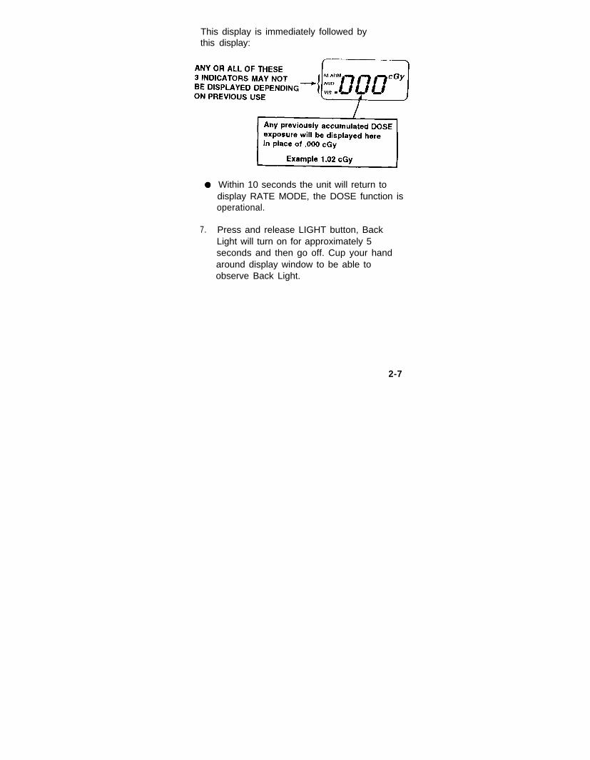
This display is immediately followed bythis display:
Within 10 seconds the unit will return todisplay RATE MODE, the DOSE function isoperational.
7. Press and release LIGHT button, BackLight will turn on for approximately 5seconds and then go off. Cup your handaround display window to be able toobserve Back Light.
2-7

8. If at any time-the following indicator isdisplayed (indicating batteries are lowbut still functional), replace the batteries(see para. 3-3 of this manual).
9. SLEEP TestIn the RATE mode, depress and holdRATE button and while holding it, press theON/OFF button for approximately 2seconds or until the display becomes blank,except for a SLP indication. Continue tohold depressed the ON/OFF and RATEbuttons, the following display will appear
followed by this
display
Release both buttons, only the SLEEP willremain indicating the unit is now in theSLEEP mode. If SLEEP indication doesn’tappear, send entire unit through Unit Levelto General Support for repairs.
2-8

10. Press and hold ON/OFF button until thedisplay returns to the RATE MODE and theSLEEP indicator disappears. Theradiacmeter is now ready for operation.(See par. 2-2 below, normal operatingprocedures). Turn unit off by depressingand holding the ON/OFF button forapproximately 2 seconds.
2-2. NORMAL OPERATINGPROCEDURES
a. Rate Operation and DoseAccumulation Reading.
1. To turn Radiacmeter on and toread Rate.
Depress and hold ON/OFFbutton for 1 to 2 seconds until aRate reading is displayed afterfirst displaying only .000 plusone or more of the following:ALARM. AUD, VIS.
2-9

The RATE, ALARM, AUD andVIS segment on the Display willbe lit or not lit, as describedbelow.
2-10

2. To read total accumulated Dose:
After unit is in Rate mode,depress the DOSE button untilthe display shows the blinkingsegment as shown below.
NOTE
When a nuclear weapon hasbeen detonated it may remainin the “blinking” state for up to10 minutes while processingthe total dose measurement.
2-11
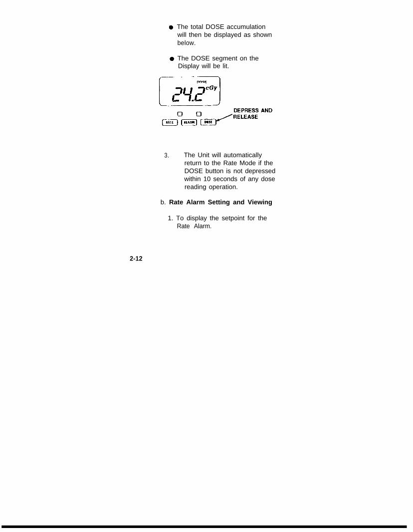
The total DOSE accumulationwill then be displayed as shownbelow.
The DOSE segment on theDisplay will be lit.
3. The Unit will automaticallyreturn to the Rate Mode if theDOSE button is not depressedwithin 10 seconds of any dosereading operation.
b. Rate Alarm Setting and Viewing
1. To display the setpoint for theRate Alarm.
2-12

Depress and hold theALARM button andthen while holding it,press the RATE button.
Release both buttons,the Display will flashthe setpoint value forRATE ALARM.
The unit will return todisplaying Rate inabout 10 seconds.
2-13

2. To Change the Setpoint for the RateAlarm.
In the RATE mode,depress and holdthe ALARM button and then the RATEbutton.
Release both buttons, the Display willflash the setpoint value for RATEALARM.
WITHIN 10 SECONDS, depress andrelease CLR/TEST button.
Repeatedly depress and release RATEbutton until desired units (cGy/hr andGy/hr) and decimal point location aredisplayed.
Depress and release CLR/TEST buttonThis action will lock in the Units andDecimal Point selected and cause theleft-most digit to flash.
2-14

Repeatedly depress andrelease the RATE button untilthe desired left most digit isdisplayed.
Depress and release theCLR/TEST button to lock in thisdigit.
Repeat the above to select andlock in the remaining digits.
Unit will display Rate Alarmsetting for approximately 10sec. and then return to RATEMODE.
2-15

3. To Select Rate Alarm Visual orAudio indications:
Depress and hold the ALARMbutton and then the Ratebutton.
Release both buttons, theDisplay will flash the setpointvalue for Rate Alarm.
Select AUD or VIS byrepeatedly depressing andreleasing the ALARM button.
Do not change the alarmsetpoints. After approximately10 seconds the unit will returnto the Rate mode and the ALMdisplay indication will be inaccordance with selectedoptions.
2-18

NOTE:
It is not possible to select the Alarmoptions when the Alarm setpoints arelower than the Rate the unit is exposedto. In this case, raise the Alarmsetpoints in accordance with step 2, onpage 2-14, and then select the desiredAlarm options.
2-17

c. Dose Alarm Settings and Viewing
1. To display the setpoint for DoseAlarm.With unit in Rate mode,depress and hold ALARMbutton and then depress DOSEbutton.Release both buttons, theDisplay will flash the setpointvalue for Dose.The unit will return to displayingDose in about 10 seconds.To return to Rate, press RATEbutton.
2-18

2. To change the Setpoints for theDose Alarm.
With unit in Rate mode,depress and hold ALARMbutton and then depress DOSEbutton.Release both buttons, theDisplay will flash the setpointvalue for Dose Alarm.WITHIN 10 SECONDS,depress and release CLR/TESTbutton.Repeatedly depress andrelease DOSE button untildesired units (cGy and Gy) anddecimal point location aredisplayed.Depress and releaseCLR/TEST button. This actionwill lock in the Units andDecimal Point selected andcause the left-most Digit toflash.Repeatedly depress andrelease the DOSE button untilthe desired left-most digit isdisplayed.
2-19

Depress and release theCLR/TEST button to lock in thisdigit.Repeat prior page to select andlock in the remaining digits.
Return to Rate by pressingRATE.
3. To reset DOSE indication to000, depress DOSE andCLR/TEST simultaneously forapproximately 5 seconds.
2-20

4. To select Dose Alarm Visual and/orAudio indications.
Depress and hold ALARMbutton then the DOSE button.Release both buttons, theDisplay will flash the setpointvalue for Dose.Select AUD or VIS byrepeatedly depressing andreleasing the ALARM button.Do not change the Alarmsetpoints. After approximately10 seconds, the unit will returnto the Dose mode and the ALMdisplay indication will be inaccordance with selectedoptions,
To return to Rate Mode pressRATE. If RATE button is notpressed, the unit will return tothe Rate Mode within 5minutes.
2-21

NOTE: It is not possible to select theAlarm options when the Alarmsetpoints are lower than theDOSE accumulated in theDosimeter Module. In thiscase, raise the alarm setpointsin accordance with step 2 onpage 2-19, and then select thedesired Alarm options.
d. Entering and Leaving SLEEP mode.
1. To enter into Sleep mode, unitmust first be in Rate mode, then:
Depress and hold the RATEand then ON/OFF button forapproximately 2 seconds oruntil display becomes blankexcept for SLP indication.Continue to hold depressed theON/OFF and RATE buttons,the following display will appear
followed by this display
Release both buttons, only the SLEEPwill remain indicating the unit is now inthe SLEEP mode.
2-22

In this mode, no RATE will bedisplayed for approximately 5minute intervals.After each 5 minute interval,the Rate will be displayed forapproximately 1 second. Theunit will again go blank for thenext 5 minute interval unlessthe Rate or Dose Alarmsetpoints are exceeded. In thatcase, the unit will revert tonormal monitoring mode andconstantly display Rate. If theDose level is above the presetalarm points (if set), the DoseAlarm will be activated.
2-23

2. To return to a continuous Ratedisplay, depress and releasethe ON/OFF button for aminimum of 2 seconds. Thiswill cause the SLEEP mode tobe discontinued. To return tothe SLEEP mode, re-enter inaccordance with step 1, para.2-2d1.
2-3. DISPLAY LIGHT OPERATION
Press light button at any time and displaylight will stay on for approximately 6seconds each time light button is pressed.
SECTION II.
2-4. BATTERY LIFE INDICATION
a. When the unit’s batteries have 600minutes or less of useful life, a blinkingBAT will appear in the top-left corner ofthe display.
2-24

b. VIEWING REMAINING BATTERYLIFE: In the RATE mode with the BATindication displayed, press theCLR/TEST button, a 3 digit number willbe displayed indicating the approximateremaining battery life in minutes,
= 190 minutes remaining.Whenever BAT is displayed, replacethe batteries as soon as possible sincethe remaining battery life number isonly a very rough approximation,
c. If at any time a lower case blinking bis displayed, indicating very lowbatteries, replace the batteries as soonas possible per para. 3-3 (page 3-2).
2-5. OPERATION UNDER UNUSUALCONDITIONS.
At temperatures below -22°F (-30°C) ittakes somewhat longer for characters toform on the display. The Radiac Setautomatically corrects for this display bysensing the ambient temperatures andincreasing the display time from 2 secondsto 5 seconds. Operation of the Radiac Setis otherwise unchanged.
2-25/(2-26 Blank)

CHAPTER 3
OPERATOR AND UNITMAINTENANCE INSTRUCTIONS
N O T ESee the Maintenance Allocation Chart(MAC) for specific operator and unit
maintenance tasks.
SECTION I
3-1. LUBRICATION INSTRUCTIONS
The AN/UDR-13 requires no periodical lubrication.Lubricants shall not be used.
SECTION II
3.2 PREVENTATIVE MAINTENANCECHECKS AND SERVICES (PMCS)
Preventative maintenance consists of routinechecks of the equipment before and after eachmission, or at any time theyRoutine checks include:
are necessary.
Conduct Preoperational Test Procedure asper page 2-1.
Cleaning (para. 3-2.1)
Inspecting battery cover gasket
3-1
Inspecting battery contacts for corrosion(remove using a pencil eraser)
3-2.1 CLEANING, DUSTING ANDWASHING THE SET
Remove dust, moisture and loosedirt from the outside surfaces of theset or set components with a cleansoft cloth. If necessary,components may be cleaned with amild solution of ordinary detergentand water and thoroughly dried, orappropriate procedures of fieldmanual (FM) 3-5.
3-3. RADIACMETER BATTERYINSTALLATION/REMOVAUREPLACEMENT
NOTE
Do not remove batteries prior to turningthe AN/UDR-13 “OFF”. Some data inmemory will be lost if this caution isnot observed.
Turn fastener 1/4 turn counterclockwise andswing batteries door open.
With the unit in a horizontal position asshown, on page 3-3, install batteries in thefollowing order observing proper polarities.
3-2

3-3
Section IIIPREPARATION FOR STORAGE OR SHIPMENT
3-4. PREPARATION FOR SHIPMENT
Perform the following step prior to shippingthe Radiac Set AN/UDR-13:
a. Remove the (4) AAA batteries fromthe Radiac Set in accordance withparagraph 3-3.
3-5. PREPARATION FOR STORAGE
Perform the following steps prior to storingthe Radiac Set AN/UDR-13:
a. Perform the routine checks of theRadiac Set listed in paragraph 3-2.
b. Remove the (4) AAA batteries fromthe Radiac Set in accordance withparagraph 3-3.
3-4
APPENDIX A
REFERENCES
A-l. SCOPE
This appendix lists all forms and publicationsreferenced in this manual.
A-2. FORMS
Recommended Changes to Publicationand Blank Forms ................................ DA Form 2028
Equipment Inspection and MaintenanceWorksheet ......................................... DA Form 2404
Discrepancy in Shipment Report(DISREP) ...........................................................SF 361
Report of Discrepancy (ROD)..........................
Quality Deficiency Report...............................
A-3. FIELD MANUALS
First Aid for Soldiers..................................
Field Manual (F) 3-5,NBC Decontamination...................................
S F 3 6 4
S F 3 6 8
FM 21-11
F M 3 - 5
Technical Bulletin ...............................TB 11-6665-364-10
A-1

A-4. MILITARY STANDARDS
Abbreviations for Use on Drawings,Specifications, Standards and inTechnical Documents...................... MIL-STD-12
A-5. MISCELLANEOUS PUBLICATIONS
Expendable/Durable Items(Except: Medical, Class VRepair Parts and Heraldic Items ........CTA 50-970
Consolidated Index of ArmyPublications and Blank Forms ............DA Pam 25-30
The Army Maintenance ManagementSystem (TAMMS)................... DA Pam 738-750
A-6. TECHNICAL BULLETINS
Field Instruction for Painting and PreservingElectronics Command Equipment IncludingCamouflage Pattern Painting of ElectricalEquipment Shelters ....................... TB 43-0118
A-7. TECHNICAL MANUALS
General Support Maintenance Manual IncludingRepair Parts and Special Tools for Radiac SetAN/UDR-13..................... TM 11-6665-364-40&P
Procedures for Destruction ofElectronics Materiel to Prevent Enemy Use(Electronics Command)................ TM 750-244-2
A-2

APPENDIX B
MAINTENANCE ALLOCATION CHART
Section I. INTRODUCTION
B-1. GENERAL.
a. This section provides a general explanation of allmaintenance and repair functions authorized atvarious maintenance categories.
b. The Maintenance Allocation Chart (MAC) inSection II designates overall responsibility for theperformance of maintenance functions on theidentified end item or component. Theimplementation of the maintenance functions uponthe end item or component will be consistent withthe assigned maintenance function.
c. Section III lists the special tools and testequipment required for each maintenance functionas referenced from Section II.
d. Section IV contains supplemental instructionsand explanatory notes for a particular maintenancefunction as referenced from Section II.
B-2. MAINTENANCE FUNCTION.
Maintenance functions will be limited to and definedas follows:
B-1

a. Inspect. To determine the serviceability of anitem by comparing its physical, mechanical, and/orelectrical characteristics with established standardsthrough examination.
b. Test. To verify serviceability by measuring themechanical or electrical characteristics of an itemand comparing those characteristics with prescribedstandards.
c. Service. Operations required periodically tokeep an item in proper operating condition, i.e., toclean (includes decontaminate, when required) topreserve, to drain, to paint, or to replenish fuel,lubricants, chemical fluids, hydraulic fluids,compressed air supplies or gases.
d. Adjust. To maintain within prescribed limits, bybringing into proper or exact position, or by settingthe operating characteristics to specifiedparameters.
e. Align. To adjust specified variable elements ofan item to bring about optimum or desiredperformance.
B-2
f. Calibrate. To determine and cause correctionsto be made or to be adjusted on instruments ortest, measuring, and diagnostic equipments used inprecision measurement. Consists of comparisonsof two instruments, one of which is a certifiedstandard of known accuracy, to detect and adjustany discrepancy in the accuracy of the instrumentbeing compared.
g. Install. The act of emplacing, seating, or fixinginto position an item, part, or module (componentor assembly) in a manner to allow the properfunctioning of an equipment or system.
h. Replace. The act of substituting a serviceablelike type part, subassembly or module (componentor assembly) for an unserviceable counterpart.
i. Repair. The application of maintenance services’or other maintenance2 to restore serviceability to anitem by correcting specific damage, fault,malfunction, or failure in a part, subassembly,module (component or assembly) end item orsystem.
1 Services - inspect, test, service, adjust, align,calibrate, or replace.2 Actions - welding, grinding, riveting, straightening,facing, remachining, or resurfacing.
B-3

j. Overhaul. That maintenance effort(service/action) necessary to restore an item to acompletely serviceable /operational condition asprescribed by maintenance standards inappropriate technical publications (i.e., DMWR).Overhaul is normally the highest degree ofmaintenance performed by the Army. Overhauldoes not normally return an item to like newcondition.
k. Rebuild. Consists of those services/actionsnecessary for the restoration of unserviceableequipment to a like new condition in accordancewith original manufacturing standards.Rebuild is the highest degree of materialmaintenance applied to Army equipment. Therebuild operation includes the act of returning tozero those age measurements (hours/miles, etc.)considered in classifying Army equipment/components.
B-3. EXPLANATION OF COLUMNS IN THE MAC,SECTION II
a. Column 1, Group Number. Column 1 listsfunctional group code numbers, the purpose ofwhich is to identify components, assemblies,subassemblies, and modules with the next higherassembly.
B-4
b. Column 2, Component/Assembly. Column 2contains the names of components, assemblies,subassemblies, and modules on whichmaintenance is authorized.
c. Column 3, Maintenance Category. Column 3lists functions to be performed on the item listed inColumn 2. (For detailed explanation of thesefunctions, see paragraph B-2).
d. Column 4, Maintenance Category. Column 4specifies by, the listing of a work time figure in theappropriate subcolumns, the lowest level categoryof maintenance authorized to perform the functionlisted in Column 3. This figure represents theactive time required to perform that maintenancefunction at the indicated category of maintenance.If the number or complexity of the tasks within thelisted maintenance function vary at differentmaintenance categories, appropriate work timefigures will be shown for each category. The worktime figure represents the average time in hoursrequired to restore an item (assembly,subassembly, component, module, end item, orsystem) to a serviceable condition under typicalfield operating conditions. This includespreparation time, troubleshooting time, and qualityassurance/quality control time in addition to thetime required to perform the specific tasks identifiedfor the maintenance functions authorized in themaintenance allocation chart.
B-5
The symbol designations for the various categoriesare as follows:
C - Operator or crewO - Unit maintenanceF - Direct support maintenanceH - General support maintenanceD - Depot maintenance
e. Column 5, Tools and Test Equipment.Column 5, specifies, by code, those common toolsets(not individual tools) and special tools, TMDE,and support equipment required to perform thedesignated function. The code in this column iskeyed to the tool and test equipment list in SectionIII.
f. Column 6, Remarks. Column 6 contains, whenapplicable, a code, which is keyed to the remarkscontained in Section IV.
B-4. EXPLANATION OF COLUMNS IN TOOLAND TEST EQUIPMENT REQUIREMENTS,SECTION III.
a. Column 1, Tool or Test Equipment ReferenceCode. The tool and test equipment reference codecorrelates with a code used in the MAC, Section II,Column 5.
B-6
b. Column 2, Maintenance Category. The lowestlevel category of maintenance authorized to use thetool or test equipment.
c. Column 3, Nomenclature. Name oridentification of the tool or test equipment.
d. Column 4, National/Nate Stock Number. Thenational stock number of the tool or test equipment.
e. Column 5, Tool Number. The manufacturerspart number.
B-5 EXPLANATION OF COLUMNS IN REMARKS,SECTION IV.
a. Column 1, Remarks Code. The code listed inColumn 6. Section II.
b. Column 2, Remarks. This column listsinformation pertinent to the maintenance functionbeing performed as indicated in the MAC,Section II.
B-7

B-
8

B-
9
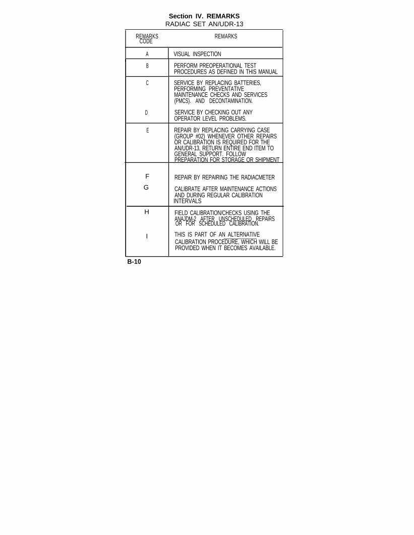
Section IV. REMARKSRADIAC SET AN/UDR-13
REMARKS REMARKSCODE
A VISUAL INSPECTION
B
C
PERFORM PREOPERATIONAL TESTPROCEDURES AS DEFINED IN THIS MANUAL
SERVICE BY REPLACING BATTERIES,PERFORMING PREVENTATIVEMAINTENANCE CHECKS AND SERVICES(PMCS). AND DECONTAMINATION.
D SERVICE BY CHECKING OUT ANYOPERATOR LEVEL PROBLEMS.
E REPAIR BY REPLACING CARRYING CASE(GROUP #02) WHENEVER OTHER REPAIRSOR CALIBRATION IS REQUIRED FOR THEAN/UDR-13, RETURN ENTIRE END ITEM TOGENERAL SUPPORT. FOLLOWPREPARATION FOR STORAGE OR SHIPMENT
F REPAIR BY REPAIRING THE RADIACMETER
G CALIBRATE AFTER MAINTENANCE ACTIONSAND DURING REGULAR CALIBRATIONINTERVALS
H FIELD CALIBRATION/CHECKS USING THEANAJDM-2 AFTER UNSCHEDULED REPAIRSOR FOR SCHEDULED CALIBRATION.
I THIS IS PART OF AN ALTERNATIVECALIBRATION PROCEDURE, WHICH WILL BEPROVIDED WHEN IT BECOMES AVAILABLE.
B-10

Section IV. REMARKSRADIAC SET AN/UDR-13
REMARKS REMARKSCODE
REPAIR BY REPLACING I.D PLATE (KEEP
REPAIRING THE MAIN ASSEMBLY.
K
L
M
REPAIR BY REPLACING COVERSUBASSEMBLY, MIDDLE, BOTTOM ANDDOSIMETER CCA’S. LARGE AND SMALL O-RINGS AND ATTACHING HARDWARE OR BYREPAIRING THE UNIT SUB-ASSEMBLY.
REPAIR BY REPLACING THE HOUSINGASSEMBLY. TOP CCA, ATTACHINGHARDWARE, AND O-RINGS.
REPAIR BY REPLACING FLAT HEAD SCREWSAND/OR SPECIAL NUTS.
N THIS IS A SPECIAL TEST FIXTURE USED FORCALIBRATION; SEE MAC SECTION Ill,REFERENCE CODE 3.
B-11/(B-12 Blank)

APPENDIX D
COMPONENTS OF END ITEM ANDBASIC ISSUE ITEMS LISTS
Section I. INTRODUCTION
D-1. SCOPE
This appendix lists components of the end item andbasic items for the AN/UDR-13 Radiac Set to helpyou inventory the items for safe and efficientoperation of the equipment.
D-2. GENERAL
The components of a End Item (COEI) and BasicIssue Items (Bll) Lists are divided into the followingsections:
a. Section II, Components of End Item.This listing is for information purposes only,and is not authority to requisitionreplacements. These items are part of theend item. As part of the end item, thesemust be with the end item whenever it isissued or transferred between propertyaccounts. Items of COEI are removed andseparately packaged for transportation orshipment only when necessary.Illustrations are furnished to help you findand identify the items.
D-1

b. Section 111, Basic Issue Items. Theseessential items are required to place theend item in operation, operate it, and to doemergency repairs. Although shippedseparately packaged, Bll must be with theend item during operation and when it istransferred between property accounts.This list is your authority to request/requisition them for replacement based onauthorization of the end item by theTOE/MTOE.
D-3. EXPLANATION OF COLUMNS
The following provides an explanation of columnsfound in the tabular listing:
a. Column (1), lllus Number, gives you thenumber of the item illustrated.
b. Column (2), National Stock Number,identifies the stock number of the item tobe used for requisitioning purposes.
c.Column (3), Description identifies theFederal item name followed by a minimumdescription when needed. The last linebelow the description is the Commercialand Government Entity Code (CAGEC) (inparentheses) and the part number.
D-2

d. Column (4), U/M (unit of measure),indicates how the item is issued for theNational Stock Number shown in columntwo.
e. Column (5), Qty Rqd, indicates thequantity required.
FIGURE D-1 RADIAC SET, AN/UDR-13;COMPONENTS OF END ITEM
D-3

Section II. COMPONENTS OF END ITEM(1)
ILLUS
NUMBERNUMBER
1
(2)NATIONAL STOCKNATIONAL STOCK
NUMBERNUMBER
N/AN/A
(3)DESCRIPTIONDESCRIPTION
CAGEC AND PARTCAGEC AND PARTNUMBERNUMBER
RADIACMETERRADIACMETER(064421(064421 A3266048A3266048 EA
* 2 6665-01-431-8172 CASE, ELECTRICALELECTRONICS, TESTAND MEASURINGEQUIPMENT
CY-97/UDR.13(06442) A3245793
EA 1
3 TB 11-6665-364-10 SIMPLIFIEDOPERATIION CARD
EA 1
Section III. BASIC ISSUE ITEMS
(1) (2) (3) (4) (5)ILLUS NATIONAL DESCRIPTION U/M QTY
NUMBER STOCK CAGEC AND PART NUMBERNUMBER
N/A PUBLICATIONTM-11-6665-364-12 EATECHNICAL MANUAL,OPERATOR’S AND UNITMAINTENANCE MANUALRADIAC SET AN/UDR-13
*UNIT LEVEL IS AUTHORIZED TOREPLACE CY-8769/UDR-13 CASE,SEE REMARK E IN SECTION IV OFMAINTENANCE ALLOCATION CHART.
D-4

APPENDIX F
EXPENDABLE/DURABLESUPPLIES AND MATERIALS LIST
Section I. ILLUSTRATION
F-1. SCOPE.
This appendix lists expendable/durable suppliesand materials you will need to operate and maintainthe Radiac Set AN/UDR-13. These items areauthorized to you by CTA 50-970, ExpandableItems (Except Medical, Class V, Repair Parts, andHeraldic Items.
F-2. EXPLANATION OF COLUMNS.
a. Column 1 - Item Number. This number isassigned to the entry in the listing and is referencedin the narrative instructions to identify the material.
b. Column 2 - Level. This column identifies thelowest level of maintenance that requires the listeditem.
C - Operator/Crew0 - Unit MaintenanceH - General Support MaintenanceD - Depot
F-1

c. Column 3 - National Stock Number. This isthe National stock number assigned to the item;use it to request or requisition the item.
d. Column 4 - Description. Indicates the Federalitem name and, if required, a description to identifythe item. The last line for each item indicates theCommercial and Government Entity Code (CAGE)in parentheses followed by the part number.
e. Column 5 - Unit of Measure (U/M). indicatesthe measure used in performing the actualmaintenance function. This measure is expressedby a two-character alphabetical abbreviation (e.g.,ea, in, pr). If the unit of measure differs from theunit of issue, requisition the lowest unit of issue thatwill satisfy your requirements.
Section II. EXPENDABLE SUPPLIES ANDMATERIALS LIST
F-2

APPENDIX GSUBJECT INDEX
ASubject
Audio, Rate Alarm..........................................Audio Dose Alarm...........................................
B
Battery Life Indication ........................................Battery Replacement...............................................
Page
2 - 1 22 - 1 8
C
Cleaning, Operating Level . . . . . . . . . . . . . .Components of End Item . . . . . . . . . . . . . . .Consolidated Index of Army Publicationsand Blank Forms . . . . . . . . . . . . . . . . . . . .
D
Data, Equipment . . . . . . . . . . . . . . . . . . .Decontamination . . . . . . . . . . . . . . . . . . .Description, Equipment . . . . . . . . . . . . . .Destruction of Army Material to PreventEnemy Use . . . . . . . . . . . . . . . . . . . . . .Display Light Operation . . . . . . . . . . . . . .Dose Accumulation Reading . . . . . . . . . .Dose Alarm Audio . . . . . . . . . . . . . . . . . .
2-243-2
3-2D-4
1-1
1-71-41-8
1-2 2-24
2-92-18
G-1

APPENDIX GSUBJECT INDEX(CONTINUED)
Subject Page
Dose Alarm Setpoint . . . . . . . . . . . . . . . .Dose Alarm Setting . . . . . . . . . . . . . . . . .Dose Alarm Visual . . . . . . . . . . . . . . . . .Dose Indication . . . . . . . . . . . . . . . . . . . .Dose Reset to Zero . . . . . . . . . . . . . . . . .
E
End Item Components ................................Equipment Characteristics, Capabilitiesand Features ..................................................Equipment Description and Data ......................Equipment Improvement Recommendation(EIR), Reporting.................................................
G
2-192-182-122-222-20
D - 4
1 - 71 - 9
1 - 3
General Information . . . . . . . . . . . . . . . . . . . 1-1Glossary . . . . . . . . . . . . . . . . . . . . . . . . . . . . 1-6
I
Instructions, Lubrication ..................................Instructions, Operating .......................................Indication, Dose.................................................I n t r o d u c t i o n . . . . . . . . . . . . . . . . . . . . . . . .
G-2
3 - 12-1
2-211-1

APPENDIX GSUBJECT INDEX(CONTINUED)
SubjectL
Location and Description ofMajor Components.............................................Lubrication Instructions .....................................
M
Maintenance Allocation Chart .............................Maintenance Forms, Records and Reports..............Maintenance, Operator .....................................Major Components, Location andDescription of Mode, Sleep ............................
N
Nomenclature Cross-Reference List................. 1-4
0
Operating Instructions ....................................Operation, Display Light....................................Operation, Rate.................................................Operation, Technical Principles of.....................Operation Under Unusual Conditions...............Operations Under Normal Conditions............. 2-9
2 - 12 - 2 42 - 91 - 1 12 - 2 5
G-3
Page
1-8 3 - 1
B-11-13-1
2-22

APPENDIX GSUBJECT INDEX(CONTINUED)
0Subject Page
Operator Preventative Maintenance Checks andServices (PMCS) ........................................................3-1
P
Preoperational Test Procedure........................................Preparation for Storage and Shipment..................... Preventative Maintenance......................................... Principles of Operation, Technical.........................
R
Rate Alarm Audio......................................Rate Operation............................................Rate Alarm Setpoint....................................Rate Alarm Setting......................................Rate Alarm Visual......................................Reading, Dose Accumulation....................Reporting Equipment ImprovementRecommendations (EIR) .......................... ...............
G-4
2-13-43-1
1-11
2 - 1 42-9
2 - 1 22 - 1 22 - 1 12 - 1 1
1-3

APPENDIX GSUBJECT INDEX(CONTINUED)
SubjectS
Page
Scope ..................................Setpoint, Dose Alarm .............Setpoint, Rate Alarm .................Setting, Dose Alarm..........Setting, Rate Alarm..............Shipment, Preparation for..........Sleep Mode............................Storage, Preparation for............
....................... 1-1...................... 2-18........................ 2-12... . . . . . . . . . . . . . . . . . 2-18. . . . . . . . . . . . . . . 2-12........................ 3-4...................... 2-22... . . . . . . . . . . . . . . . . . . 3-4
T
Technical Principles of Operations............................1-11
U
Unusual Conditions, Operation Under...................... 2-25
G-5(G-6 Blank)


PIN: 076799-000