Embed Size (px)
DESCRIPTION
TM 3-6665-343-23&P
Citation preview
TM 3-6665-343-23&P
UNIT AND DIRECT SUPPORT MAINTENANCE MANUAL(INCLUDING REPAIR PARTS AND SPECIAL TOOLS LIST)
FOR
IMPROVEDCHEMICAL AGENT MONITOR (ICAM)
(NSN 6665-01-357-8502) (EIC:5AB)
WARNING - This document contains export-controlled technical data whose export is restricted by theArmy Export Control Act (Title 22, U.S.C., Sec 2751 et seq) or executive order 12470. Violations of theseexport laws are subject to sever criminal penalties.
DISTRIBUTION STATEMENT C: Distribution authorized to U.S. Government agencies and theircontractors to protect technical or operational information. This determination was made on 12November, 1991. Other requests for this document will be referred to: Tech Director, U.S. ArmyEdgewood Research, Development and Engineering Center, ATTN: SCBRD-ENL-V, Aberdeen ProvingGround, MD 21010-5423
DESTRUCTION NOTICE - Destroy by any method that will prevent disclosure of contents orreconstruction of the document.
HEADQUARTERS, DEPARTMENT OF THE ARMY9 JUNE 1998
TM 3-6665-343-23&P
WARNING
RADIATION HAZARD
NICKEL-63 (Ni-63)
Wipe test must be performed before and after any maintenance or testing of CAM.
Contamination can become airborne by heated air and smoke from fire. Stand upwind of fire to avoid inhalation ofpossible contamination.
The Chemical Agent Monitor (CAM) contains a beta radiation source in the quantity which requires a NuclearRegulatory Commission (NRC) license to possess items which contain the source. The CAM contains 10millicuries of Nickel-63. The Nickel-63 plated cylinder is the source which ionizes chemical agents allowing fortheir detection.
If the CAM is lost or stolen, notify the NBC Officer/NCO and the local Radiation Protection Officer (RPO)immediately. Lost or stolen CAMs are reportable to the Nuclear Regulatory Commission (NRC) by the licenseholder. Report must be made through the local RPO to the Armament and Chemical Acquisition and LogisticsActivity (ACALA) Safety Office, DSN 793-2965/2995/6228.
The source is totally enclosed and protected by the CAM case. However the CAM is potentially dangerous ifbroken.
SAFETY PRECAUTIONS
1. Handle the CAM carefully.
2. If CAM case is broken or cracked, inform the NBC Officer/NCO, and if available, the local Radiation ProtectionOfficer (RPO).
3. A CAM damaged beyond the repair capability of direct support should be wrapped in a plastic bag and shipped inoriginal packing container, if available, to depot maintenance for repair. If skin contact is made with any areathought to be contaminated with Nickel-63, wash immediately with nonabrasive soap and water.
4. Follow safety procedures for storage, shipment, and disposal in accordance with this manual, local regulations,AR 710-3 and AR 385-11.
a
TM 3-6665-343-23&P
WARNING
LITHIUM SULFUR DIOXIDE BATTERIES: Do not attempt to decontaminate CAMbatteries. Dispose of batteries according to TB 43-0130 and local Standing OperatingProcedures (SOP).
FLAMMABLE AND CORROSIVE HAZARD
Lithium sulfur dioxide batteries contain lithium, sulfur dioxide and an electrolyte. Sulfur dioxide is anirritant gas. The electrolyte is flammable and highly corrosive. Do not immerse in water or deconsolution, crush, or burn batteries. Do not attempt to recharge batteries or store at temperatures above158°F (70°C). If a battery is mishandled or misused, the lithium may rapidly vent out, carrying with it thesulfur dioxide gas and the electrolyte, and it may heat up. If this happens, stay away until the smell ofsulfur is gone. If you have to move the battery, move it outside by using a shovel or long tongs. Wearsuitable protection when handling suspect batteries. A rapidly venting battery may create an explosiveand corrosive hazard which may cause damage to skin and eyes. If skin or eyes come in contact with theelectrolyte, wash thoroughly with generous amounts of water and seek medical attention. Dispose ofbatteries according to TB 43-0130 and local SOP.
WARNING
DANGER-HIGH VOLTAGE-1000 VOLTS DC
1000 volts DC is present on the Printed Circuit Board (PCB) when monitor case is removed. Danger ofelectrical shock exists if PCB is touched while CAM is operating.
CAUTION
Do not decontaminate CAM or its accessories with M258A1 or M280 Decontamination Kits. These kitsmay cause false positives and temporarily render the CAM inoperative.
FIRST AID
For first aid information, refer to FM 1-11.
b
TM 3-6665-343-23&P
TECHNICAL MANUAL HEADQUARTERSNo. 3-6665-343-23&P Department of the Army
Washington, DC, 9 June 1998
UNIT AND DIRECT SUPPORT MAINTENANCE MANUAL(INCLUDING REPAIR PARTS AND SPECIAL TOOLS LIST)
FORIMPROVED CHEMICAL AGENT MONITOR (ICAM)
NSN 6665-01-357-8502 (EIC:5AB)
REPORTING ERRORS AND RECOMMENDING IMPROVEMENTS
You can help improve this manual. If you find any mistakes or know of a way to improve the procedures,please let us know. Mail your letter, DA Form 2028 (Recommended Changes to Publications and BlankForms), or DA Form 2028-2 located in the back of this manual directly to Technical Director, U.S. ArmyEdgewood Research, Development and Engineering Center, ATTN: SCBRD-ENL-V, Aberdeen ProvingGround, MD 21010-5423. A reply will be furnished to you.
WARNING - This document contains export-controlled technical data whose export is restricted by theArmy Export Control Act (Title 22, U.S.C., Sec 2751 et seq) or Executive Order 12470. Violations ofthese export laws are subject to severe criminal penalties.
DISTRIBUTION STATEMENT C: Distribution authorized to U.S. Government agencies and theircontractors to protect technical or operational information. This determination was made on 12November 1991. Other requests for this document will be referred to Technical Director, U.S. ArmyEdgewood Research, Development and Engineering Center, ATTN: SCBRD-ENL-V, Aberdeen ProvingGround, MD 21010-5423
DESTRUCTION NOTICE - Destroy by any method that will prevent disclosure of contents orreconstruction of the document.
TABLE OF CONTENTSPage
CHAPTER 1
Section I
Section II
Section III
Section IV
HOW TO USE THIS MANUAL---------------------------------------------------------
INTRODUCTION--------------------------------------------------------------------------
General Information ---------------------------------------------------------------------
Equipment Description and Data -----------------------------------------------------
Repair Parts, Special Tools; Test, Measurement ---------------------------------and Diagnostic Equipment (TMDE); and Support Equipment
Principles of Operation-------------------------------------------------------------------
iii
1-1
1-1
1-4
1-7
1-8
i
TM 3-6665-343-23&P
TABLE OF CONTENTS (CONT)
CHAPTER 2
Section I
Section II
Section III
Section IV
Section V
CHAPTER 3
Section I
Section II
Section III
Section IV
Section V
APPENDIX A
APPENDIX B
APPENDIX C
Section I
Section II
Group 00
Group 01
Section III
Section IV
APPENDIX D
Section I
Section II
APPENDIX E
Page
UNIT MAINTENANCE INSTRUCTIONS ------------------------------------------------------------2-1
Service Upon Receipt ------------------------------------------------------------------------------------2-1
Preventive Maintenance Checks and Services (PMCS)-----------------------------------------2-3
Unit Troubleshooting--------------------------------------------------------------------------------------2-4
Unit Maintenance Procedures------------------------------------------------------------------------ 2-10
Preparation for Storage or Shipment --------------------------------------------------------------- 2-10
DIRECT SUPPORT MAINTENANCE INSTRUCTIONS-----------------------------------------3-1
Radiological Safety Instructions------------------------------------------------------------------------3-1
Service Upon Receipt ------------------------------------------------------------------------------------3-4
Direct Support Troubleshooting---------------------------------------------------------------------- 3-20
Direct Support Maintenance Procedures ---------------------------------------------------------- 3-78
Preparation for Storage or Shipment ------------------------------------------------------------- 3-142
REFERENCES-------------------------------------------------------------------------------------------- A-1
MAINTENANCE ALLOCATION CHART ---------------------------------------------------------- B-1
REPAIR PARTS AND SPECIAL TOOLS LIST -------------------------------------------------- C-1
Introduction ------------------------------------------------------------------------------------------------ C-1
Repair Parts List --------------------------------------------------------------------------------------- C-1-1
Monitor, Chemical Agent (ICAM) ------------------------------------------------------------------ C-1-1
Monitor Kit, CAM -------------------------------------------------------------------------------------- C-2-1
0101 Monitor, Chemical Agent --------------------------------------------------------------------- C-3-1
010101 Module Assembly, Monitor --------------------------------------------------------------- C-4-1
01010101 Monitor Assembly ----------------------------------------------------------------------- C-5-1
0101010101 Module, Drift Tube ------------------------------------------------------------------- C-6-1
010102 Case Assembly, Monitor ------------------------------------------------------------------ C-7-1
0102 Carrying Case Assembly--------------------------------------------------------------------- C-8-1
Special Tools List (Not Applicable)
National Stock Number, Part Number, and Reference Designator Indexes ------------- C-I-1
EXPENDABLE AND DURABLE ITEMS LIST---------------------------------------------------- D-1
Introduction ------------------------------------------------------------------------------------------------ D-1
Expendable and Durable Items List------------------------------------------------------------------ D-2
NUCLEAR REGULATORY COMMISSION REQUIREMENTS ------------------------------ E-1
INDEX------------------------------------------------------------------------------------------------- Index-1
Illus/
Figure
C-1
C-2
C-3
C-4
C-5
C-6
C-7
C-8
ii
TM 3-6665-343-23&PHOW TO USE THIS MANUAL
This manual contains a number of features that enable the user to locate information easily. The table of contentscontains a general list of information sections. A comprehensive cross-referenced index is located at the end of themanual. It will also help the user locate specific information.
Chapter 1 contains introductory information. Topics of special importance include equipment description and data,location and description of major components, safety, and principles of operation.
Chapter 2 contains information at the unit maintenance level. Topics of special importance include service uponreceipt, preventive maintenance checks and services, troubleshooting, maintenance procedures and preparation forstorage or shipment.
Chapter 3 contains information at the direct support maintenance level. Topics of special importance includeradiological safety instructions, service upon receipt, troubleshooting, maintenance, and preparation for storage orshipment.
When a CAM arrives at Direct Support for repair, use the information in Chapter 3 to test, troubleshoot, repair andretest the CAM. Use the following steps as a guide:
1. Get the equipment required for testing and troubleshooting a CAM. This equipment is listed in para 3-12. Thenprepare the Diagnostic Test Set (for use in testing and troubleshooting the CAM) as instructed in para 3-14.
2. Perform the operational check of the CAM presented in para 3-15. If you come to a part of the operational check thatcannot be accomplished, refer to the symptom for the problem. (Para 3-11 lists possible symptoms that could occurduring the operational check.) Turn to the page in the manual for troubleshooting the symptom.
3. Follow the troubleshooting logic tree for the symptom. The tree will refer you to a maintenance procedure or to furthertesting. Further testing consists of more detailed tests: cell test, leak test, pump test, and waveform test.
4. Turn to the maintenance procedure and perform the indicated maintenance action. The procedure begins with aninitial setup: a listing of the tools and materials needed to complete the task, and the equipment condition prior toperformance of the maintenance task. The equipment conditions are a list of the maintenance tasks that must beaccomplished before the present task is started. Do the equipment condition tasks first.
5. The specific maintenance task is then performed. The task usually consists of removal and installation procedures.Once the specific task is completed, return to the beginning of the task at the equipment conditions listing. Reversethe order of equipment condition steps to place the CAM back into a fully assembled condition.
6. Return again to the troubleshooting tree for further direction in trouble analysis or additional testing. Tasks in thetroubleshooting tree end by performing the operational check to see that the CAM has been completely returned tooperational status.
7. Perform wipe test before returning to user (para 3-7).
A Repair Parts and Special Tools List (RPSTL) that lists and authorizes spares and repair parts, tools,special tools, Test, Measurement and Diagnostic Equipment (TMDE), and support equipment required forperformance of maintenance of the CAM is supplied in Appendix C. Refer to page C-1 for detailed information onusing the RPSTL.
iii
TM 3-6665-343-23&P
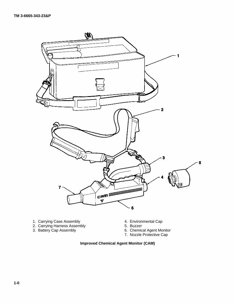
1. Carrying Case Assembly2. Carrying Harness Assembly3. Battery Cap Assembly
4. Environmental Cap5. Buzzer6. Chemical Agent Monitor7. Nozzle Protective Cap
Improved Chemical Agent Monitor (CAM)
1-0
TM 3-6665-343-23&P
CHAPTER 1INTRODUCTION
Section I. GENERAL INFORMATION
1-1. SCOPE.
NOTE
The monitor, page 1-0 item 6, will show an NSN on the case; however, the monitor itself isnot stocked, stored, or issued. To obtain a new monitor the next higher assembly must berequisitioned. (See system NSN on the front of this manual.)
a. Type of Manual. Unit and Direct Support Maintenance including Repair Parts and Special Tools List.
b. Model Number and Equipment Name. No model number; Improved Chemical Agent Monitor (ICAM).
c. Purpose of Equipment. Used by ground forces to search out clean areas, to search and locatecontamination on personnel, equipment, ships' structures, aircraft and land vehicles, buildings and terrain, and to monitorthe boundaries of collective protection. The CAM responds to nerve and mustard agent vapors down to the lowestconcentrations that could affect personnel over a short period.
d. Special Limitations on Equipment. The CAM is a monitor. It is not a detector; therefore, it can becomecontaminated and overloaded. The CAM only reports conditions at the front of the inlet nozzle. It is only a point monitorand cannot give a realistic assessment of the vapor hazard over an area from one position. Maintenance must beperformed in a clean work area and rubber gloves worn to avoid contaminating CAM.
1-2. MAINTENANCE FORMS, RECORDS, AND REPORTS.
a. Maintenance. Department of the Army forms and procedures used for equipment maintenance will bethose prescribed by DA PAM 738-750, The Army Maintenance Management System (TAMMS) as contained in theMaintenance Management Update.
b. Testing and Tracking. For Department of Army procedures for tracking and wipe testing the cell (acomponent of the CAM) through its life cycle, refer to AR 710-3, Chapter 3.
c. Shipments/Receipts. When transporting a CAM, refer to AR 385-11. Also see para 3-62 and 3-63.
d. Report of Packaging and Handling Deficiencies. Fill out and forward SF 364 (Report of Discrepancy)as prescribed in AR 735-11-2.
e. Discrepancy In Shipment Report. Fill out and forward Discrepancy in Shipment Report (SF 361) asprescribed in AR 55-38.
f. Radiological Accident Reports, RCS DD-SD (AR) 1168. Fill out and forward as prescribed in AR 385-40.
1-3. DESTRUCTION OF ARMY MATERIEL TO PREVENT ENEMY USE.Destroy the CAM in accordance with TM 43-0002-31, procedures for destruction of alarm systems.
1-1
TM 3-6665-343-23&P
1-4. PREPARATION FOR STORAGE OR SHIPMENT.Refer to para 3-62 and 3-63 for special instructions concerning storage or shipment.
1-5. NOMENCLATURE CROSS-REFERENCE LIST.
Common NameBattery Cap AssemblyConnector AssemblyDisplay AssemblyEnvironmental CapLong and Short PillarNozzle Seal
Official NomenclatureRetainer BatteryConnector ReceptacleOptoelectronic DisplayProtective Dust CapThreaded StandoffSpacer Sleeve
1-6. LIST OF ABBREVIATIONS.
ACA/DCAMDCDC-DCDMMDTSEHTGHIMSLCDLEDNRCPCBRAMVdc°C°F
Alternating CurrentAnalog/DigitalChemical Agent MonitorDirect CurrentDirect Current to Direct CurrentDigital MultimeterDiagnostic Test SetExtra High TensionNerve AgentMustard AgentIon Mobility SpectrometryLiquid Crystal DisplayLight Emitting DiodeNuclear Regulatory CommissionPrinted Circuit BoardRandom Access MemoryVolts Direct CurrentDegrees Centigrade (Celsius)Degrees Fahrenheit
1-7. REPORTING EQUIPMENT IMPROVEMENT RECOMMENDATIONS (EIR).
If your CAM needs improvement, let us know. Send us a SF 368 (Product Quality Deficiency Report). You, theuser, are the only one who can tell us what you do not like about your equipment. Let us know why you do not like thedesign or performance. Mail it to the address specified in DA PAM 738-750. A reply will be furnished to you.
1-8. SAFETY, CARE, AND HANDLING.
a. Rules and Regulations. The CAM contains a radioactive source which is controlled by the U.S. NuclearRegulatory Commission (NRC) under Title 10 Code of Federal Regulations. AR 385-11 and 700-64 implement NRCregulations. Army-wide possession and use of the CAM is authorized by an NRC Byproduct Materials License issued tothe Armament and Chemical Acquisition and Logistics Activity, Attn: AMSTA-AC-SF, Rock Island, IL 61299-7630. Thelicense is issued on the basis of statements concerning procedures established for the life-cycle control of the CAM. TheCAM units are issued to Army activities through the Armament and Chemical Acquisition and Logistics Activity NationalInventory Control Point, (AMSTA-AC-CTC-D). The serial numbers of the CAM and drift tube module are tracked by AR710-3, Chapter 4, Section 2. Please notify your Cell Serialization Surety Officer (CSSO) to process the serial numbertransactions with the DOD Central Registry.
1-2

TM 3-6665-343-23&P
b. Wipe test. The wipe test (para 3-7) must be performed upon receipt and before and after all maintenanceand testing is complete.
c. Posting Requirements. Federal law requires certain notices, instructions, and standards be madeavailable to all users of items which contain licensed radioactive material. In lieu of posting this information, pages areattached at the back of this technical manual for reference. These pages contain instructions about Title 10 Code ofFederal Regulations, NRC Form 3 (Notice to Employees) and Public Law 93-438.
d. Repair/Disposition. Unserviceable CAM will be returned to depot.
e. Emergency Procedures.
NOTE
In any emergency event, radioactive contamination must be consideredto be present until determined otherwise.
(1) Fire. In a fire emergency, the basic concern is possible airborne contamination carried out of theflames by the heated air and in the smoke. Firefighters should fight the fire from upwind, and wearportable air systems, if available. After the fire has been extinguished, debris must be surveyed forthe presence of equipment containing Nickel-63 sources. The RADIAC meter AN/VDR-2 (with thebeta window open) is suitable for detecting the location of the Nickel-63 sources. Wipes must betaken and evaluated to determine contamination location.
(2) Equipment Destruction. In an equipment destruction emergency, parts of the equipment must beretrieved, and surveys for possible contamination must be done.
(3) Accident Response in General.
(a) Remove injured and spectators.(b) Establish exclusion area.(c) Determine extent of radiation with AN/VDR-2 (or equivalent).(d) Notify authorities (NBC NCO or officer, and, if available, local RPO).
1-9. CORROSION PREVENTION AND CONTROL (CPC).
a. Corrosion Prevention and Control (CPC) of Army Materiel is a continuing concern. It is important that anycorrosion problems with this item be reported so that the problem can be corrected and improvements can be made toprevent the problem in future items.
1-3
TM 3-6665-343-23&P
1-9. CORROSION PREVENTION AND CONTROL (CPC) (CONT).
b. While corrosion is typically associated with rusting of metals, it can also include deterioration of materialssuch as rubber and plastic. Unusual cracking, softening, swelling, or breaking of these materials may be a corrosionproblem.
c. Such problems should be reported using SF 368 (Quality Deficiency Report). Mail it to the addressspecified in DA PAM 738-750.
Use of key words such as corrosion, rust, deterioration, or cracking will assure that the information is identified asa CPC problem.
1-10. CALIBRATION.
The CAM does not require calibration.
Section II. EQUIPMENT DESCRIPTION AND DATA
1-11. EQUIPMENT CHARACTERISTICS, CAPABILITIES, AND FEATURES.
a. Portable, hand-held instrument designed to determine and indicate the hazard from nerve or mustardagent vapor present in the air.
b. Held in either hand while dressed in any level of nuclear, biological, and chemical (NBC) andenvironmental protective clothing.
c. Used to search out clean areas, to search for and locate contamination on personnel, equipment, ship'sstructures, aircraft and land vehicles, buildings and terrain, and to monitor the boundaries of collective protection.
d. Responds to nerve and mustard agent vapors down to the lowest concentrations that could affectpersonnel over a short period.
e. Operates on one battery. Battery life varies with frequency of use and with temperature. At 68°F (20°C),a fresh battery will last at least 12 hours.
f. Can be operated on an external power supply.
g. Easy to operate: only two controls.
h. Relative vapor hazard level indicated on a Liquid Crystal Display (LCD).
1-4
TM 3-6665-343-23&P
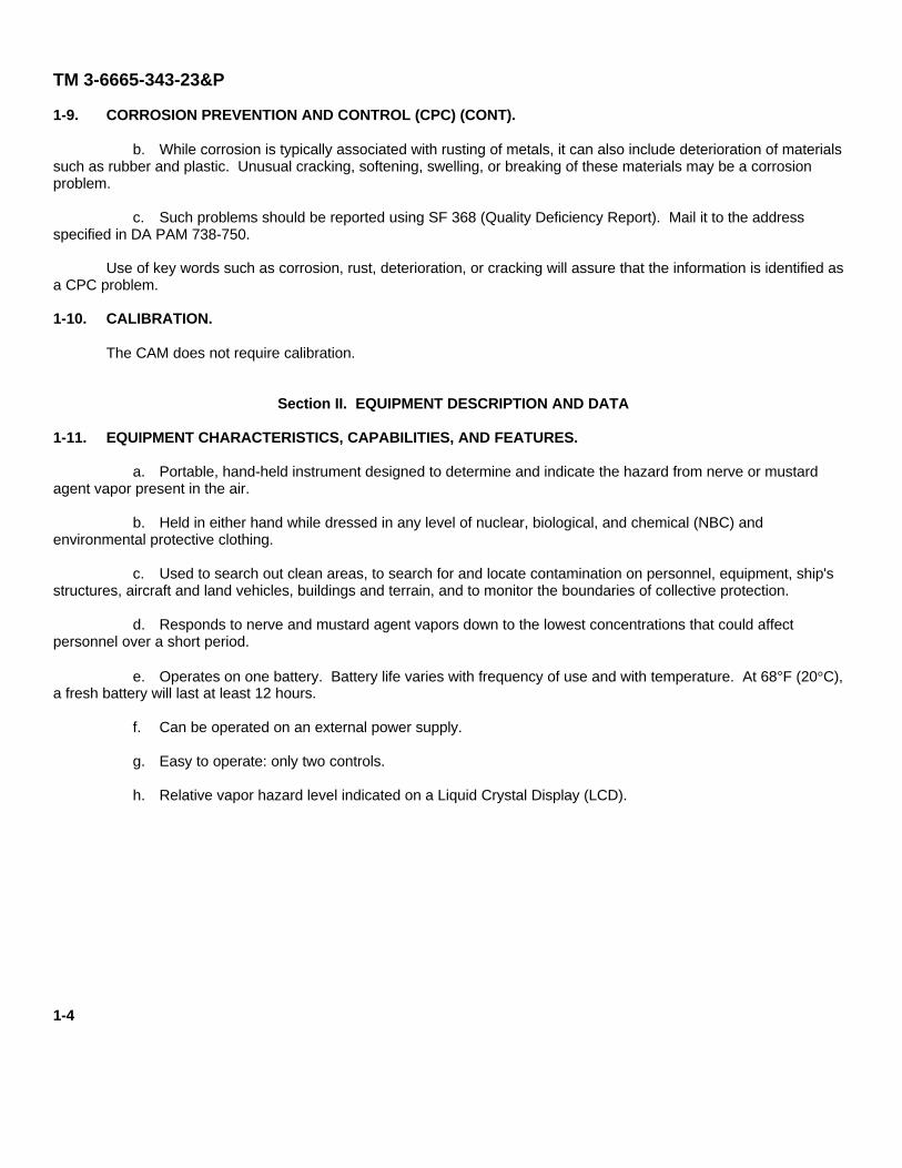
1-12. LOCATION AND DESCRIPTION OF MAJOR COMPONENTS.
a. Nozzle Protective Cap (1). Protects nozzle assembly and ensures that clean air is sampled when CAMis started.
b. Nozzle Assembly (2). Chemical agent vapors are drawn in through this inlet for analysis by the CAM. Aheater wire is wound around the tubular section of the molding. Nozzle assembly is secured to CAM with a specialbayonet type locking ring. A special tool from the diagnostic test set is used to remove it from the CAM.
c. Case-Front End (3). Provides a common attachment point for the nozzle protective cap, nozzleassembly, nozzle holder assembly, and drift tube module.
d. Display Assembly (4). Display is a liquid crystal device back-lit by light emitting diodes (LEDs). Displayshows operating status and hazard level, and aids in indicating a malfunction. The ON/OFF and G/H mode switches arepart of the assembly. The mode switch controls the polarity of the cell to enable the cell to handle either positive nerveagent ions or negative mustard agent ions. Two sealed rubber pads cover the switch push-buttons.
e. Battery Contact Assembly (5). Provides spring loaded contact to mate with the battery terminals andinterconnect battery power to the CAM.
f. Case Assembly (6). Houses display assembly and battery contact assembly. Case assembly fits overthe monitor module assembly.
g. Battery Cap Assembly (7). Bayonet fitting cap which retains the battery.
1-5
TM 3-6665-343-23&P
1-12. LOCATION AND DESCRIPTION OF MAJOR COMPONENTS (CONT).
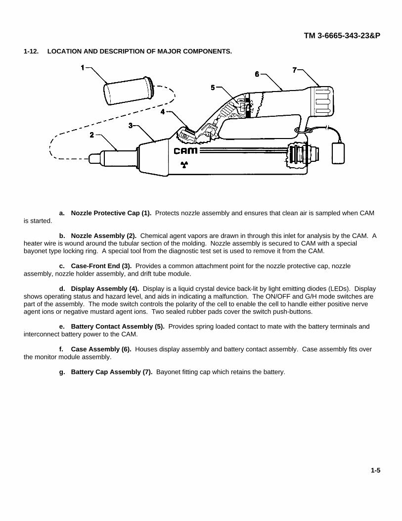
h. Locknut (8). Locknut is removed to gain access to the internal parts of the CAM. It also acts as aretainer for the disc that contains the serial number of the drift tube module and CAM lot number.
i. Environmental Cap Assembly (9). Consists of a tether-bayonet fitting cap protecting the connectorassembly. Provides storage for nozzle protective cap during operation.
j. Connector Assembly (10). Provides diagnostic electronic connections for use during maintenance.
k. Sieve Pack Assembly (11). A molecular sieve which filters the CAM recirculatory air.
I. Pump Assembly (12). Consists of two silicone rubber diaphragm pumps driven by a DC motor and yokemechanism.
m. Drift Tube Module (13). Consists of a cell assembly, manifold assembly, and membrane assembly. Thecell assembly, which contains the radioactive source, is in the form of a stack of components held together with stainlesssteel rods and a retaining clip. Two of the rods are drilled with holes to provide airflow paths for the drift and sourceregions of the cell; the rods also link the return airflow through the molecular sieve assembly and pump assembly. Amembrane assembly is located at the forward end of the cell assembly. The membrane assembly is a thin silicone rubberlayer that forms a division between the outside air and the controlled environment inside the analysis section of the CAM.The membrane permits chemical agent vapor molecules to permeate the cell assembly. Membrane is heated to about250°F (120°C). The serial number of the drift tube module is located on a disc near the locknut (8) on the end of the CAM.The serial number is also etched on the manifold block assembly of the drift tube module.
1-6
TM 3-6665-343-23&P
n. Printed Circuit Board (PCB) (14). A printed circuit board that contains the microprocessor.
o. Monitor Module Assembly (15). Consists of a locknut, sieve pack assembly, pump assembly, drift tubemodule and printed circuit board.
p. Confidence Sample (16). Used to test the CAM for its ability to detect G and H. The end with a roundcross-section is marked G and contains nerve agent simulant. The ribbed end is marked H and contains mustard agentsimulant. Housed in carrying harness pocket.
q. Buzzer (17). Attaches to electrical connector and provides an audible alarm when CAM displays two ormore bars.
Section III. REPAIR PARTS; TOOLS; SPECIAL TOOLS; TEST MEASUREMENT ANDDIAGNOSTIC EQUIPMENT (TMDE); AND SUPPORT EQUIPMENT
1-13. COMMON TOOLS AND EQUIPMENT.
For authorized common tools and equipment, refer to the Modified Table of Organization and Equipment (MTOE)applicable to your unit.
1-14. SPECIAL TOOLS, TMDE, AND SUPPORT EQUIPMENT.
Special tools and TMDE are listed in the Maintenance Allocation Chart in Appendix B of this manual. Supportequipment is not needed. Additionally authorized items are listed in TM 3-6665-343-10.
1-15. REPAIR PARTS.
Repair parts are listed and illustrated in the Repair Parts and Special Tools List in Appendix C of this manual.
1-7

TM 3-6665-343-23&P
Section IV. PRINCIPLES OF OPERATION
1-16. INTRODUCTION.
The CAM samples air in the immediate vicinity of the nozzle for the presence of G or H chemical agents. Airsample conditions a short distance away from the CAM may be quite different, and a change in wind direction couldquickly bring a hazardous level of agent vapor to a previously safe area.
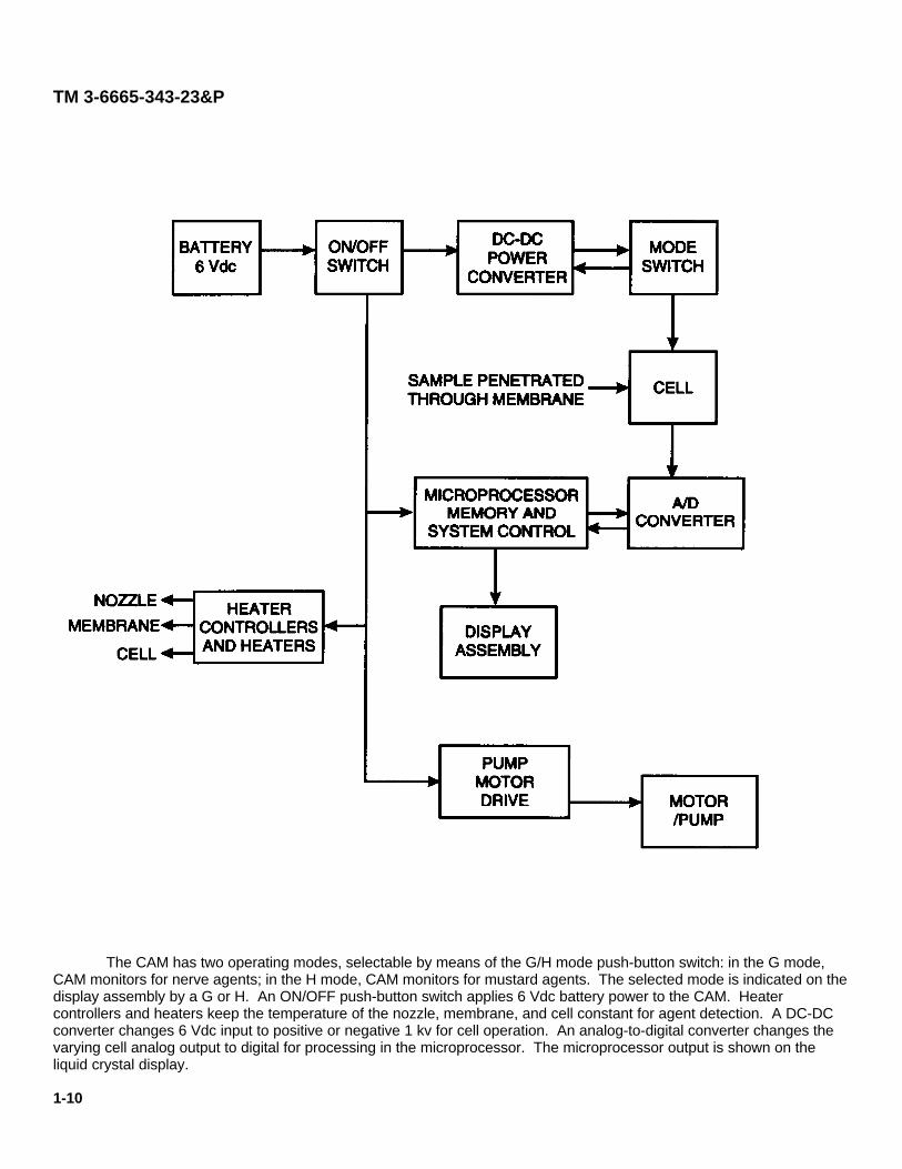
An internal motor/pump assembly (sample pump) continually draws air in through the nozzle assembly. The air isthen passed over a heated membrane assembly before being exhausted back into the atmosphere via an exhaust vent atthe side of the nozzle assembly. Any agent vapor present in the air permeates the membrane assembly and the cellassembly. In the cell assembly, the vapor molecules are electrically charged (ionized) by a weak radioactive source inorder that the vapor molecules can be detected. These charged particles are used to produce an electronic signal bymeans of a process called Ion Mobility Spectrometry (IMS).
Agent ions in the cell assembly are swept towards a collector electrode which produces an electrical impulse foreach ion received. The current produced by this electrode is analyzed by a microprocessor which drives the displayassembly. From the characteristics of this signal, CAM determines the concentration of the nerve or mustard agentpresent and indicates the vapor hazard by displaying a number of bars on the display assembly.
The closed cell assembly system air is circulated by a recirculating pump through molecular sieves which keep thesystem dry and chemically clean. The G/H mode push button switch reverses the voltages in the cell assembly to suitnerve or mustard agent vapor which have opposite charges when ionized. Acetone vapor is introduced into the closedcirculatory system to stabilize the response of the CAM in the nerve agent mode.
1-8

TM 3-6665-343-23&P
Principles of Operation
1-9
TM 3-6665-343-23&P
The CAM has two operating modes, selectable by means of the G/H mode push-button switch: in the G mode,CAM monitors for nerve agents; in the H mode, CAM monitors for mustard agents. The selected mode is indicated on thedisplay assembly by a G or H. An ON/OFF push-button switch applies 6 Vdc battery power to the CAM. Heatercontrollers and heaters keep the temperature of the nozzle, membrane, and cell constant for agent detection. A DC-DCconverter changes 6 Vdc input to positive or negative 1 kv for cell operation. An analog-to-digital converter changes thevarying cell analog output to digital for processing in the microprocessor. The microprocessor output is shown on theliquid crystal display.
1-10
TM 3-6665-343-23&P
THREE DOTS
The three dots on the far right of the display are used normally only as a diagnostic indication.
If at any time during normal operation the processor loses the Reactant Ion Peak (RIP) (i.e., the RIP, alwaysmonitored, does not meet the preset height and position criteria), the three dots will be activated. This would normallyhappen briefly after a mode change or during excessive dosage of agent or simulant (as they have a greater chargeaffinity than air). During this period, the unit will still operate normally as the processor is using the last known referencefor the RIP (from RAM).
If, however, the processor does not find a RIP again within about 30 minutes of its disappearance (normally thiswould be caused only by either gross contamination or equipment failure), a fault condition signal is given to the operator.This failure signal comprises all eight bars and the WAIT symbol flashing at a frequency of approximately 2Hz.
1-11/(1-12 blank)
TM 3-6665-343-23&PCHAPTER 2
UNIT MAINTENANCE INSTRUCTIONS
Section I. SERVICE UPON RECEIPT
2-1. INTRODUCTION.
This section provides the information the unit maintenance technician needs to inspect and service the ChemicalAgent Monitor (CAM) before issuing it to the operator.
Table 2-1. Service Upon Receipt – CAM
LOCATION/ITEM ACTION
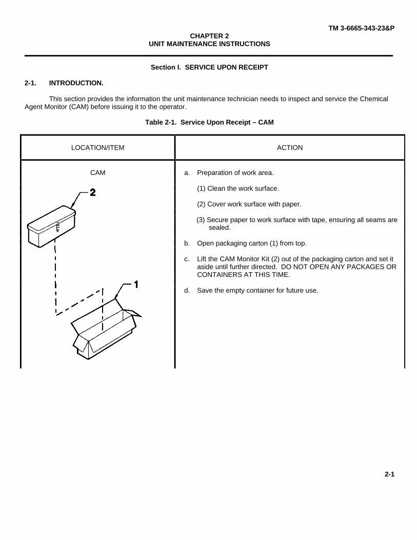
a. Preparation of work area.
(1) Clean the work surface.
(2) Cover work surface with paper.
(3) Secure paper to work surface with tape, ensuring all seams aresealed.
b. Open packaging carton (1) from top.
c. Lift the CAM Monitor Kit (2) out of the packaging carton and set itaside until further directed. DO NOT OPEN ANY PACKAGES ORCONTAINERS AT THIS TIME.
CAM
d. Save the empty container for future use.
2-1
TM 3-6665-343-23&P
Table 2-1. Service Upon Receipt - CAM (Cont)
LOCATION/ITEM ACTION
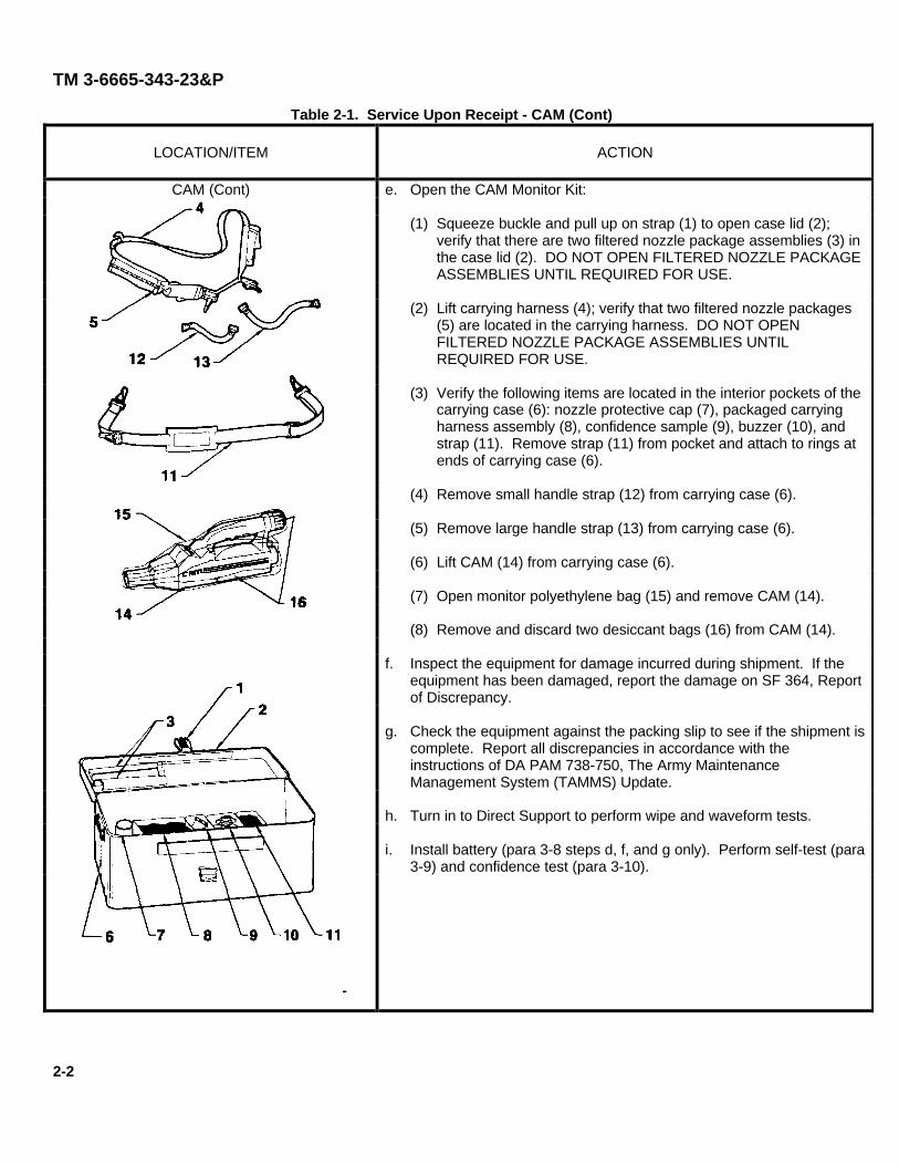
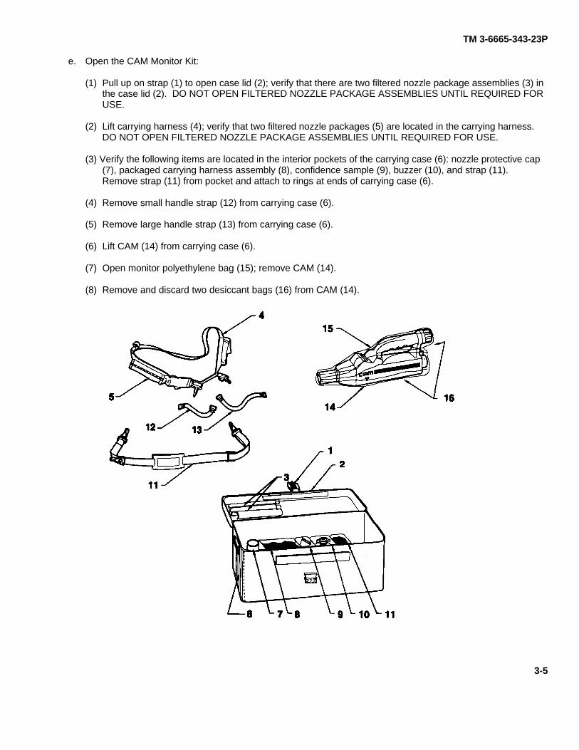
e. Open the CAM Monitor Kit:
(1) Squeeze buckle and pull up on strap (1) to open case lid (2);verify that there are two filtered nozzle package assemblies (3) inthe case lid (2). DO NOT OPEN FILTERED NOZZLE PACKAGEASSEMBLIES UNTIL REQUIRED FOR USE.
(2) Lift carrying harness (4); verify that two filtered nozzle packages(5) are located in the carrying harness. DO NOT OPENFILTERED NOZZLE PACKAGE ASSEMBLIES UNTILREQUIRED FOR USE.
(3) Verify the following items are located in the interior pockets of thecarrying case (6): nozzle protective cap (7), packaged carryingharness assembly (8), confidence sample (9), buzzer (10), andstrap (11). Remove strap (11) from pocket and attach to rings atends of carrying case (6).
(4) Remove small handle strap (12) from carrying case (6).
(5) Remove large handle strap (13) from carrying case (6).
(6) Lift CAM (14) from carrying case (6).
(7) Open monitor polyethylene bag (15) and remove CAM (14).
(8) Remove and discard two desiccant bags (16) from CAM (14).
f. Inspect the equipment for damage incurred during shipment. If theequipment has been damaged, report the damage on SF 364, Reportof Discrepancy.
g. Check the equipment against the packing slip to see if the shipment iscomplete. Report all discrepancies in accordance with theinstructions of DA PAM 738-750, The Army MaintenanceManagement System (TAMMS) Update.
h. Turn in to Direct Support to perform wipe and waveform tests.
i. Install battery (para 3-8 steps d, f, and g only). Perform self-test (para3-9) and confidence test (para 3-10).
CAM (Cont)
2-2
TM 3-6665-343-23&P
Section II. PREVENTIVE MAINTENANCE CHECKS AND SERVICES (PMCS)
2-2. UNIT PROCEDURES.
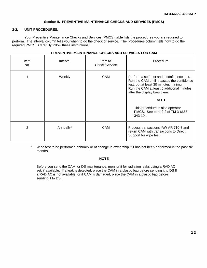
Your Preventive Maintenance Checks and Services (PMCS) table lists the procedures you are required toperform. The interval column tells you when to do the check or service. The procedures column tells how to do therequired PMCS. Carefully follow these instructions.
PREVENTIVE MAINTENANCE CHECKS AND SERVICES FOR CAM
Item Interval Item to ProcedureNo. Check/Service
1 Weekly CAM Perform a self-test and a confidence test.Run the CAM until it passes the confidencetest, but at least 30 minutes minimum.Run the CAM at least 5 additional minutesafter the display bars clear.
NOTE
This procedure is also operatorPMCS. See para 2-2 of TM 3-6665-343-10.
2 Annually* CAM Process transactions IAW AR 710-3 andreturn CAM with transactions to DirectSupport for wipe test.
* Wipe test to be performed annually or at change in ownership if it has not been performed in the past sixmonths.
NOTE
Before you send the CAM for DS maintenance, monitor it for radiation leaks using a RADIACset, if available. If a leak is detected, place the CAM in a plastic bag before sending it to DS Ifa RADIAC is not available, or if CAM is damaged, place the CAM in a plastic bag beforesending it to DS.
2-3
TM 3-6665-343-23&P
Section III. UNIT TROUBLESHOOTING
2-3. INTRODUCTION.
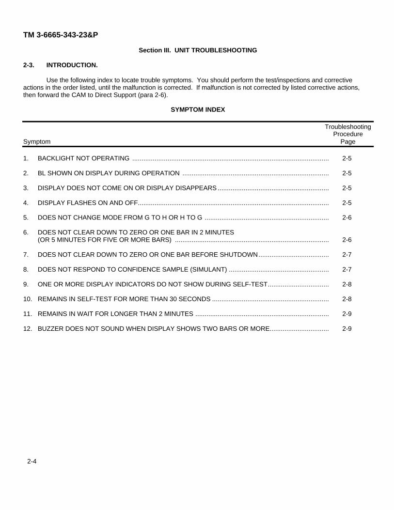
Use the following index to locate trouble symptoms. You should perform the test/inspections and correctiveactions in the order listed, until the malfunction is corrected. If malfunction is not corrected by listed corrective actions,then forward the CAM to Direct Support (para 2-6).
SYMPTOM INDEX
TroubleshootingProcedure
Symptom Page
1. BACKLIGHT NOT OPERATING ..........................................................................................................
2. BL SHOWN ON DISPLAY DURING OPERATION ...............................................................................
3. DISPLAY DOES NOT COME ON OR DISPLAY DISAPPEARS ............................................................
4. DISPLAY FLASHES ON AND OFF.......................................................................................................
5. DOES NOT CHANGE MODE FROM G TO H OR H TO G ...................................................................
6. DOES NOT CLEAR DOWN TO ZERO OR ONE BAR IN 2 MINUTES(OR 5 MINUTES FOR FIVE OR MORE BARS) ...................................................................................
7. DOES NOT CLEAR DOWN TO ZERO OR ONE BAR BEFORE SHUTDOWN......................................
8. DOES NOT RESPOND TO CONFIDENCE SAMPLE (SIMULANT) ......................................................
9. ONE OR MORE DISPLAY INDICATORS DO NOT SHOW DURING SELF-TEST.................................
10. REMAINS IN SELF-TEST FOR MORE THAN 30 SECONDS ...............................................................
11. REMAINS IN WAIT FOR LONGER THAN 2 MINUTES ........................................................................
12. BUZZER DOES NOT SOUND WHEN DISPLAY SHOWS TWO BARS OR MORE................................
2-5
2-5
2-5
2-5
2-6
2-6
2-7
2-7
2-8
2-8
2-9
2-9
2-4
TM 3-6665-343-23&P
Table 2-3. Unit Troubleshooting
MALFUNCTIONTEST OR INSPECTION
CORRECTIVE ACTION
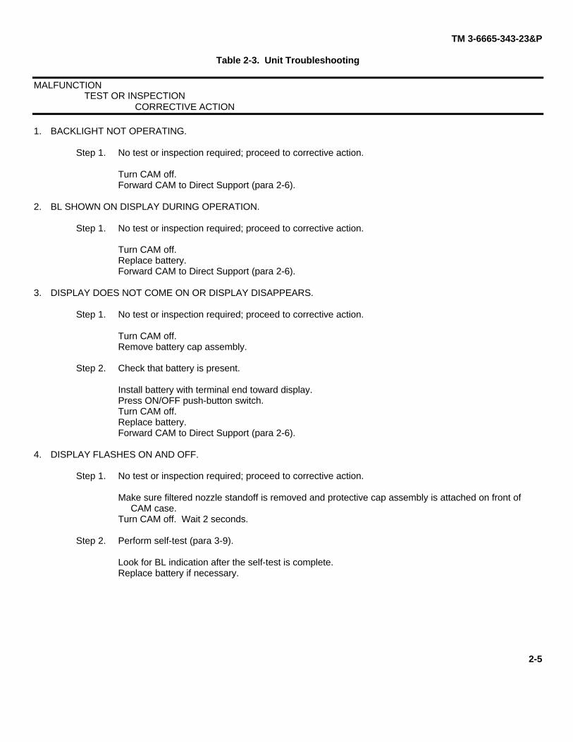
1. BACKLIGHT NOT OPERATING.
Step 1. No test or inspection required; proceed to corrective action.
Turn CAM off.Forward CAM to Direct Support (para 2-6).
2. BL SHOWN ON DISPLAY DURING OPERATION.
Step 1. No test or inspection required; proceed to corrective action.
Turn CAM off.Replace battery.Forward CAM to Direct Support (para 2-6).
3. DISPLAY DOES NOT COME ON OR DISPLAY DISAPPEARS.
Step 1. No test or inspection required; proceed to corrective action.
Turn CAM off.Remove battery cap assembly.
Step 2. Check that battery is present.
Install battery with terminal end toward display.Press ON/OFF push-button switch.Turn CAM off.Replace battery.Forward CAM to Direct Support (para 2-6).
4. DISPLAY FLASHES ON AND OFF.
Step 1. No test or inspection required; proceed to corrective action.
Make sure filtered nozzle standoff is removed and protective cap assembly is attached on front ofCAM case.
Turn CAM off. Wait 2 seconds.
Step 2. Perform self-test (para 3-9).
Look for BL indication after the self-test is complete.Replace battery if necessary.
2-5
TM 3-6665-343-23&P
Table 2-3. Unit Troubleshooting (Cont)
MALFUNCTIONTEST OR INSPECTION
CORRECTIVE ACTION
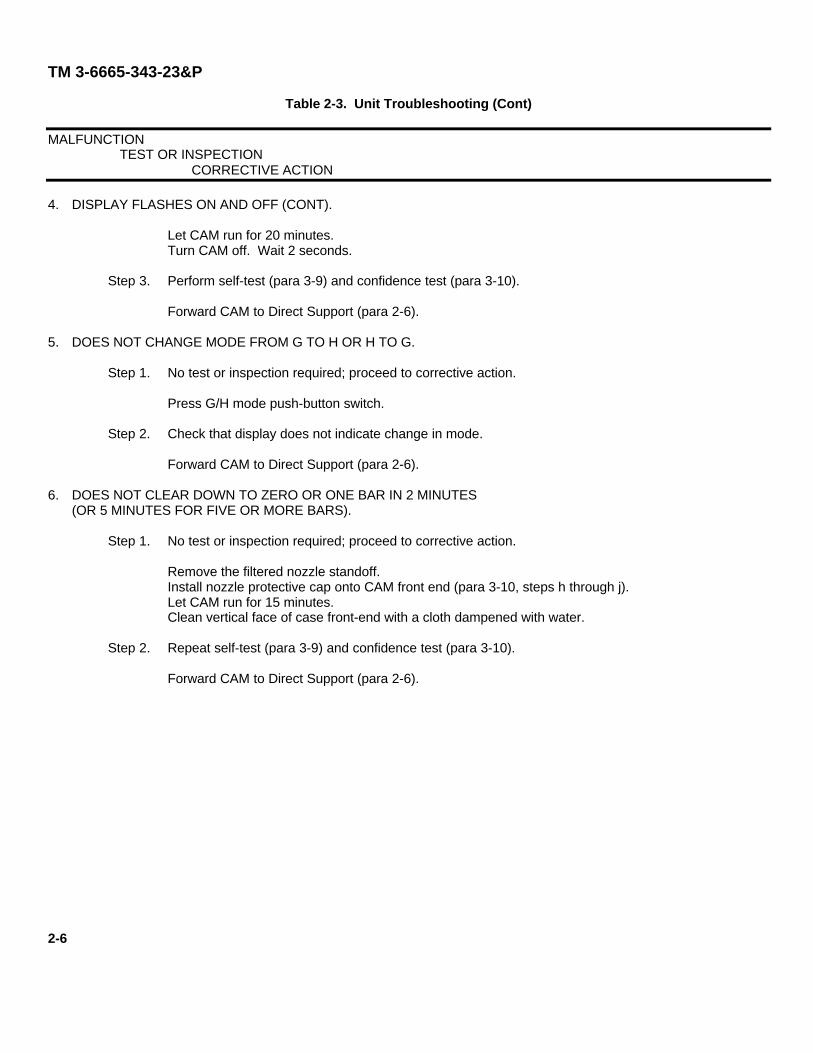
4. DISPLAY FLASHES ON AND OFF (CONT).
Let CAM run for 20 minutes.Turn CAM off. Wait 2 seconds.
Step 3. Perform self-test (para 3-9) and confidence test (para 3-10).
Forward CAM to Direct Support (para 2-6).
5. DOES NOT CHANGE MODE FROM G TO H OR H TO G.
Step 1. No test or inspection required; proceed to corrective action.
Press G/H mode push-button switch.
Step 2. Check that display does not indicate change in mode.
Forward CAM to Direct Support (para 2-6).
6. DOES NOT CLEAR DOWN TO ZERO OR ONE BAR IN 2 MINUTES(OR 5 MINUTES FOR FIVE OR MORE BARS).
Step 1. No test or inspection required; proceed to corrective action.
Remove the filtered nozzle standoff.Install nozzle protective cap onto CAM front end (para 3-10, steps h through j).Let CAM run for 15 minutes.Clean vertical face of case front-end with a cloth dampened with water.
Step 2. Repeat self-test (para 3-9) and confidence test (para 3-10).
Forward CAM to Direct Support (para 2-6).
2-6
TM 3-6665-343-23&P
Table 2-3. Unit Troubleshooting (Cont)
MALFUNCTIONTEST OR INSPECTION
CORRECTIVE ACTION
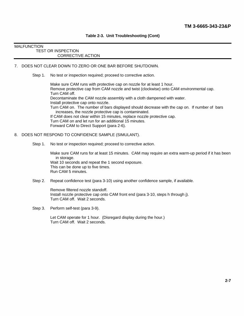
7. DOES NOT CLEAR DOWN TO ZERO OR ONE BAR BEFORE SHUTDOWN.
Step 1. No test or inspection required; proceed to corrective action.
Make sure CAM runs with protective cap on nozzle for at least 1 hour.Remove protective cap from CAM nozzle and twist (clockwise) onto CAM environmental cap.Turn CAM off.Decontaminate the CAM nozzle assembly with a cloth dampened with water.Install protective cap onto nozzle.Turn CAM on. The number of bars displayed should decrease with the cap on. If number of bars
increases, the nozzle protective cap is contaminated.If CAM does not clear within 15 minutes, replace nozzle protective cap.Turn CAM on and let run for an additional 15 minutes.Forward CAM to Direct Support (para 2-6).
8. DOES NOT RESPOND TO CONFIDENCE SAMPLE (SIMULANT).
Step 1. No test or inspection required; proceed to corrective action.
Make sure CAM runs for at least 15 minutes. CAM may require an extra warm-up period if it has beenin storage.
Wait 10 seconds and repeat the 1 second exposure.This can be done up to five times.Run CAM 5 minutes.
Step 2. Repeat confidence test (para 3-10) using another confidence sample, if available.
Remove filtered nozzle standoff.Install nozzle protective cap onto CAM front end (para 3-10, steps h through j).Turn CAM off. Wait 2 seconds.
Step 3. Perform self-test (para 3-9).
Let CAM operate for 1 hour. (Disregard display during the hour.)Turn CAM off. Wait 2 seconds.
2-7
TM 3-6665-343-23&P
Table 2-3. Unit Troubleshooting (Cont)
MALFUNCTIONTEST OR INSPECTION
CORRECTIVE ACTION
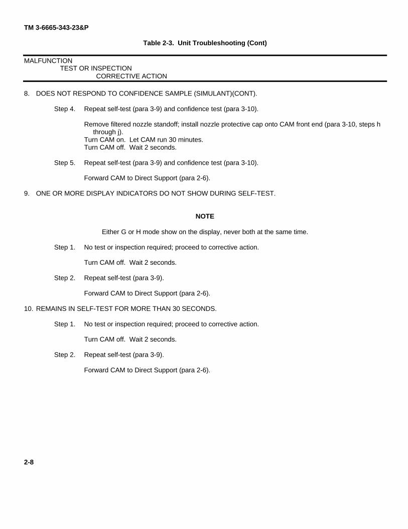
8. DOES NOT RESPOND TO CONFIDENCE SAMPLE (SIMULANT)(CONT).
Step 4. Repeat self-test (para 3-9) and confidence test (para 3-10).
Remove filtered nozzle standoff; install nozzle protective cap onto CAM front end (para 3-10, steps hthrough j).
Turn CAM on. Let CAM run 30 minutes.Turn CAM off. Wait 2 seconds.
Step 5. Repeat self-test (para 3-9) and confidence test (para 3-10).
Forward CAM to Direct Support (para 2-6).
9. ONE OR MORE DISPLAY INDICATORS DO NOT SHOW DURING SELF-TEST.
NOTE
Either G or H mode show on the display, never both at the same time.
Step 1. No test or inspection required; proceed to corrective action.
Turn CAM off. Wait 2 seconds.
Step 2. Repeat self-test (para 3-9).
Forward CAM to Direct Support (para 2-6).
10. REMAINS IN SELF-TEST FOR MORE THAN 30 SECONDS.
Step 1. No test or inspection required; proceed to corrective action.
Turn CAM off. Wait 2 seconds.
Step 2. Repeat self-test (para 3-9).
Forward CAM to Direct Support (para 2-6).
2-8
TM 3-6665-343-23&P
Table 2-3. Unit Troubleshooting (Cont)
MALFUNCTIONTEST OR INSPECTION
CORRECTIVE ACTION
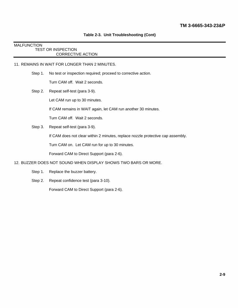
11. REMAINS IN WAIT FOR LONGER THAN 2 MINUTES.
Step 1. No test or inspection required; proceed to corrective action.
Turn CAM off. Wait 2 seconds.
Step 2. Repeat self-test (para 3-9).
Let CAM run up to 30 minutes.
If CAM remains in WAIT again, let CAM run another 30 minutes.
Turn CAM off. Wait 2 seconds.
Step 3. Repeat self-test (para 3-9).
If CAM does not clear within 2 minutes, replace nozzle protective cap assembly.
Turn CAM on. Let CAM run for up to 30 minutes.
Forward CAM to Direct Support (para 2-6).
12. BUZZER DOES NOT SOUND WHEN DISPLAY SHOWS TWO BARS OR MORE.
Step 1. Replace the buzzer battery.
Step 2. Repeat confidence test (para 3-10).
Forward CAM to Direct Support (para 2-6).
2-9
TM 3-6665-343-23&P
Section IV. UNIT MAINTENANCE PROCEDURES
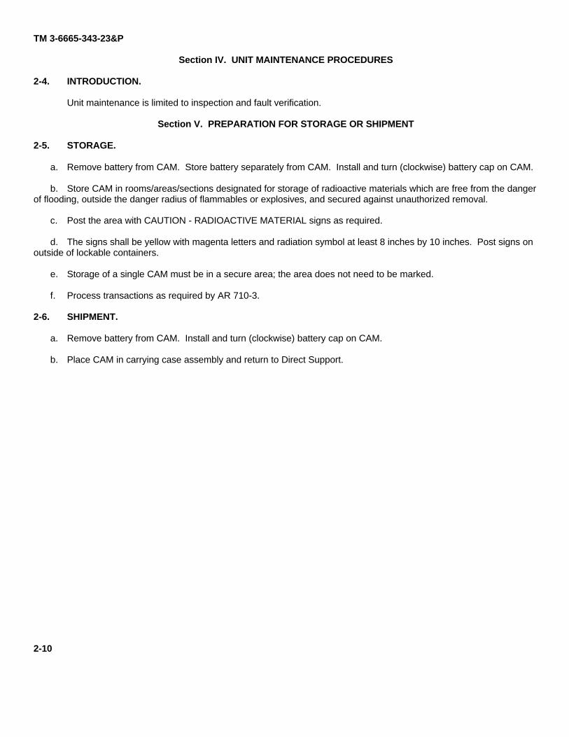
2-4. INTRODUCTION.
Unit maintenance is limited to inspection and fault verification.
Section V. PREPARATION FOR STORAGE OR SHIPMENT
2-5. STORAGE.
a. Remove battery from CAM. Store battery separately from CAM. Install and turn (clockwise) battery cap on CAM.
b. Store CAM in rooms/areas/sections designated for storage of radioactive materials which are free from the dangerof flooding, outside the danger radius of flammables or explosives, and secured against unauthorized removal.
c. Post the area with CAUTION - RADIOACTIVE MATERIAL signs as required.
d. The signs shall be yellow with magenta letters and radiation symbol at least 8 inches by 10 inches. Post signs onoutside of lockable containers.
e. Storage of a single CAM must be in a secure area; the area does not need to be marked.
f. Process transactions as required by AR 710-3.
2-6. SHIPMENT.
a. Remove battery from CAM. Install and turn (clockwise) battery cap on CAM.
b. Place CAM in carrying case assembly and return to Direct Support.
2-10
TM 3-6665-343-23P
CHAPTER 3DIRECT SUPPORT MAINTENANCE INSTRUCTIONS
Section I. RADIOLOGICAL SAFETY INSTRUCTIONS
WARNING
RADIATION HAZARD
NICKEL-63 (Ni-63)
Wipe test must be performed before and after any maintenance or testing ofChemical Agent Monitor (CAM).
CAUTION
To avoid contamination of equipment DO NOT:Smoke, eat, or drink in work area.Use aftershave or perfume.Use cleaning agents, floor wax sprays, adhesives, paint, or similar items.Use insect or skin repellents.Handle internal parts without wearing rubber gloves.
NOTE
CAM performance may be affected by EMI when attached to the DTS. Avoidperforming maintenance tasks near equipment emitting high electromagneticradiation.
3-1. WORK AREA.
INITIAL SETUP
Tools/Equipment
RADIAC Set AN/VDR-2 (or equivalent)
Materials/PartsPaper (Item 5, App D)Tape (Item 8, App D)Gloves (Item 4, App D)Plastic Bag (Item 1, App D)Wipe Test Kit (Item 10, App D)Ball Point Pen (Item 6, App D)Soap (Item 7, App D)
3-1
TM 3-6665-343-23P
3-1. WORK AREA (CONT).
a. Preparation of Work Area.
(1) Clean the work surface.
(2) Cover work surface with paper.
(3) Secure paper to work surface with tape, insuring all seams are sealed.
b. Work Area Cleanup and Decontamination.
NOTE
Work area must be wiped and the wipe surveyed with AN/VDR-2, or equivalent, forpresence of Nickel-63 contamination at conclusion of work EACH day that maintenanceoperations are performed. Surveys must be documented.
(1) Record wipe test information IAW para 3-7. a. Identify the area (e.g., Bldg 51) on the form. Set aside vialand form.
(2) Wear disposable gloves.
(3) Fold paper inward to hold in contamination and place in plastic bag.
(4) Take a wipe test of the area with a moistened wipe test filter from the wipe test kit (Item 10, App D).Evaluate the wipe test filter with AN/VDR-2, or equivalent. It should read no more than twice background.If the reading is higher, stop cleanup and contact the RPO.
(5) Dispose of gloves in plastic bag. Seal bag.
(6) Using a ball point pen, mark: "RADIOACTIVE MATERIAL Ni-63" on a piece of tape and apply the tape tothe plastic bag. Set aside bag pending lab results of wipe test.
(7) Place the wipe test filter in the prepared vial. Send this wipe test for evaluation to the Rock IslandLaboratory identified in para 3-7, along with the CAM wipes.
(8) Wash hands for 2 minutes with soap at conclusion of maintenance or testing of CAM and at conclusion ofany work area cleanup operations.
(9) Dispose of bag as regular or radioactive waste, depending upon lab test results.
3-2. ACCOUNTABILITY.
For instructions on completing necessary transactions, contact your Cell Serialization Surety Officer (CSSO) inaccordance with AR 710-3, Chapter 4, Section 2. A transaction is required for each of the following:
a. Inventory loss.
b. Suspected loss or theft.
3-2
TM 3-6665-343-23P
c. Receipt.
d. Shipment.
e. Demilitarization.
f. Wipe test result.
g. Removal of a drift tube module from CAM.
h. Insertion of a drift tube module into CAM.
3-3. FIRE AND EXPLOSION EMERGENCIES.
a. Fire Emergencies.
WARNING
RADIATION HAZARD
NICKEL-63 (Ni-63)Contamination can become airborne by heated air and smoke from fire. Stand upwind of fire to avoidinhalation of possible contamination.
(1) Notify all personnel to evacuate area or building and to stand upwind of heat and smoke.
(2) Notify fire department of fire and possible hazards, and that self-contained breathing apparatus should beworn.
(3) Turn off all ventilation equipment.
(4) Close all doors and windows.
(5) Notify your NBC NCO or Officer, or RPO.
b. Explosion Emergencies.
(1) Care for injured (FM 21-11).
(2) Notify your NBC NCO or Officer, or RPO.
(3) Notify medical team.
(4) Cordon off area.3-3
TM 3-6665-343-23PSection II. SERVICE UPON RECEIPT
3-4. INTRODUCTION.
This section describes unpacking, checking unpacked equipment, wipe test, assembly and preparation of CAM foruse, self-test, and confidence test.
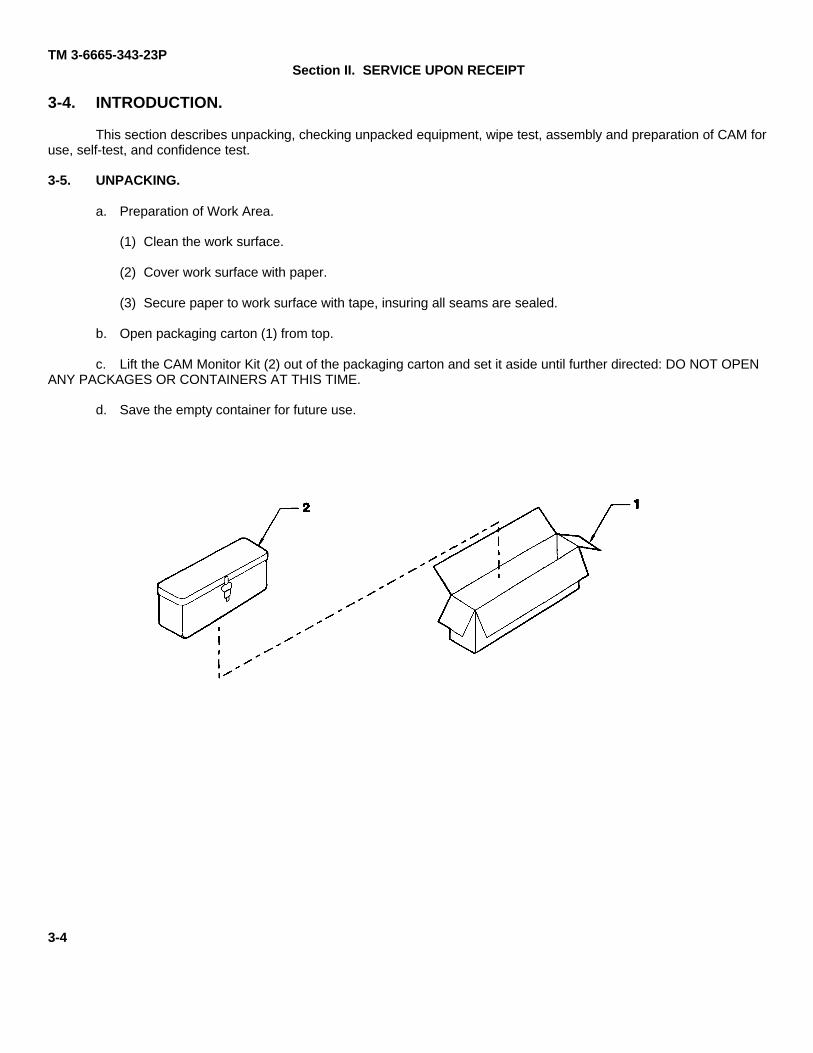
3-5. UNPACKING.
a. Preparation of Work Area.
(1) Clean the work surface.
(2) Cover work surface with paper.
(3) Secure paper to work surface with tape, insuring all seams are sealed.
b. Open packaging carton (1) from top.
c. Lift the CAM Monitor Kit (2) out of the packaging carton and set it aside until further directed: DO NOT OPENANY PACKAGES OR CONTAINERS AT THIS TIME.
d. Save the empty container for future use.
3-4
TM 3-6665-343-23P
e. Open the CAM Monitor Kit:
(1) Pull up on strap (1) to open case lid (2); verify that there are two filtered nozzle package assemblies (3) inthe case lid (2). DO NOT OPEN FILTERED NOZZLE PACKAGE ASSEMBLIES UNTIL REQUIRED FORUSE.
(2) Lift carrying harness (4); verify that two filtered nozzle packages (5) are located in the carrying harness.DO NOT OPEN FILTERED NOZZLE PACKAGE ASSEMBLIES UNTIL REQUIRED FOR USE.
(3) Verify the following items are located in the interior pockets of the carrying case (6): nozzle protective cap(7), packaged carrying harness assembly (8), confidence sample (9), buzzer (10), and strap (11).Remove strap (11) from pocket and attach to rings at ends of carrying case (6).
(4) Remove small handle strap (12) from carrying case (6).
(5) Remove large handle strap (13) from carrying case (6).
(6) Lift CAM (14) from carrying case (6).
(7) Open monitor polyethylene bag (15); remove CAM (14).
(8) Remove and discard two desiccant bags (16) from CAM (14).
3-5
TM 3-6665-343-23P
3-6. CHECKING UNPACKED EQUIPMENT.
a. Inspection. Inspect the equipment for damage incurred during shipment. If the equipment has beendamaged, report the damage on SF 364, Report of Discrepancy.
b. Check the equipment against the packing slip to see if the shipment is complete. Report all discrepancies inaccordance with the instructions of DA PAM 738-750, The Army Maintenance Management System (TAMMS) Update.
3-7. WIPE TEST.
WARNING
Do not lick envelopes to seal them or ingestion of Nickel-63 may result.
NOTE
Perform wipe test annually or at change in ownership if it has not been performed in thepast six months.
a. Recording Information.
(1) If needed, make additional copies of the RIA Wipe Test Request Form that is supplied in the wipe test kit(Item 10, App D).
(2) Record the following information on the Wipe Test Request Form: complete mailing address, POC, DSNor commercial phone and fax numbers, date wipes were taken, and reporting activity DODAAC. Use aball-point pen (Item 6, App D).
(3) Using the felt marker provided in the kit, assign a number to the top of the cap of the plastic vial.
NOTE
Do not mark on the side of the plastic vial or the wipe test may not be readable.
(4) Mark the same number in the column marked "VIAL NO." on the Wipe Test Request Form along with thecorresponding owning activity DODAAC. Indicate an A for annual wipe or M for maintenance wipe.
b. Wipe Test Procedures.
NOTE
To avoid mixing up samples, perform each wipe test after recording each CAM's serialnumber on the Wipe Test Request Form.
(1) Wear disposable gloves.
(2) Twist (counterclockwise) and remove environmental cap (1) from CAM (2). Let environmental cap hangon its tether (3).
3-6
TM 3-6665-343-23P
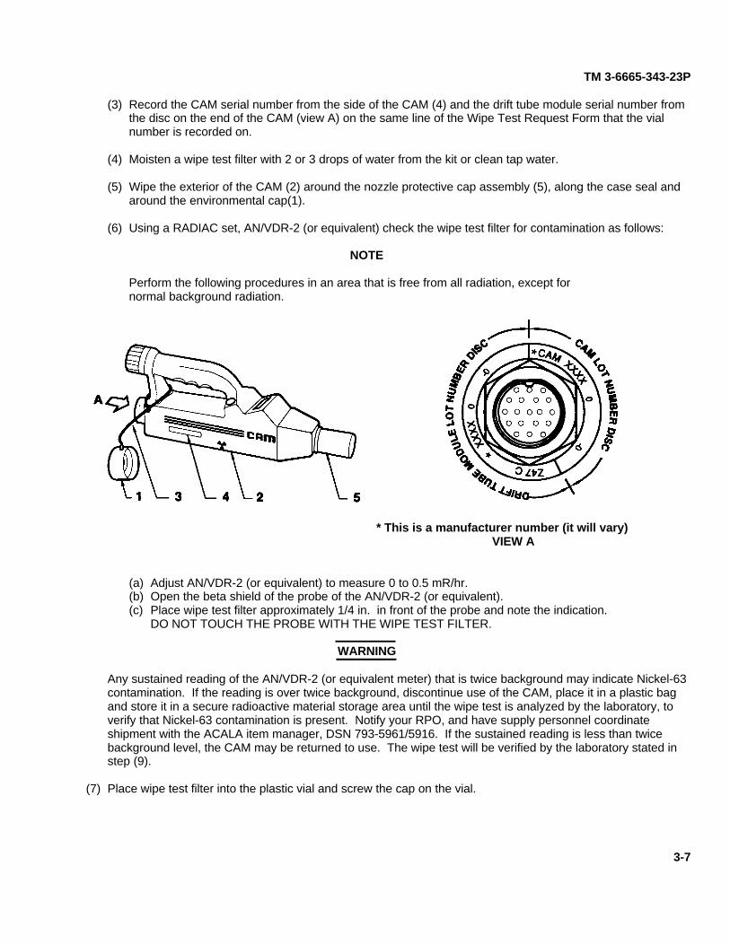
(3) Record the CAM serial number from the side of the CAM (4) and the drift tube module serial number fromthe disc on the end of the CAM (view A) on the same line of the Wipe Test Request Form that the vialnumber is recorded on.
(4) Moisten a wipe test filter with 2 or 3 drops of water from the kit or clean tap water.
(5) Wipe the exterior of the CAM (2) around the nozzle protective cap assembly (5), along the case seal andaround the environmental cap(1).
(6) Using a RADIAC set, AN/VDR-2 (or equivalent) check the wipe test filter for contamination as follows:
NOTE
Perform the following procedures in an area that is free from all radiation, except fornormal background radiation.
* This is a manufacturer number (it will vary)VIEW A
(a) Adjust AN/VDR-2 (or equivalent) to measure 0 to 0.5 mR/hr.(b) Open the beta shield of the probe of the AN/VDR-2 (or equivalent).(c) Place wipe test filter approximately 1/4 in. in front of the probe and note the indication.
DO NOT TOUCH THE PROBE WITH THE WIPE TEST FILTER.
WARNING
Any sustained reading of the AN/VDR-2 (or equivalent meter) that is twice background may indicate Nickel-63contamination. If the reading is over twice background, discontinue use of the CAM, place it in a plastic bagand store it in a secure radioactive material storage area until the wipe test is analyzed by the laboratory, toverify that Nickel-63 contamination is present. Notify your RPO, and have supply personnel coordinateshipment with the ACALA item manager, DSN 793-5961/5916. If the sustained reading is less than twicebackground level, the CAM may be returned to use. The wipe test will be verified by the laboratory stated instep (9).
(7) Place wipe test filter into the plastic vial and screw the cap on the vial.
3-7
TM 3-6665-343-23P
3-7. WIPE TEST (CONT).
WARNING
Do not lick packaging envelopes to seal them or ingestion of Ni-63 may result.
(8) Place the numbered vial(s) along with the Wipe Test Request Form in the pre-addressed packagingenvelope provided or other sturdy packaging. Seal the package. Mark the envelope: MAIL ROOM - DONOT OPEN.
(9) Mail samples to the following address:
Commander, Rock Island ArsenalRadiation Test Lab/Radiation Wipe Test SamplesATTN: SIORI-SEL/RIA RPORodman Ave.Bldg 210, Room 407Rock Island, IL 61299-5000
(10) Results of the wipe test evaluated by the laboratory will be sent to the address entered on the Wipe TestRequest Form.
(11) The CAM can be used immediately after wipe testing unless leakage of Nickel-63 is suspected or anaccident has occurred.
(12) Proceed with work area cleanup and Decontamination (para 3-1b) or Direct Support troubleshooting (para3-11) as appropriate.
3-8. ASSEMBLY AND PREPARATION OF CAM FOR USE.
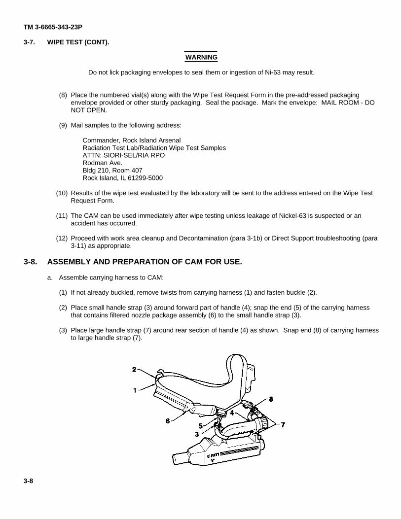
a. Assemble carrying harness to CAM:
(1) If not already buckled, remove twists from carrying harness (1) and fasten buckle (2).
(2) Place small handle strap (3) around forward part of handle (4); snap the end (5) of the carrying harnessthat contains filtered nozzle package assembly (6) to the small handle strap (3).
(3) Place large handle strap (7) around rear section of handle (4) as shown. Snap end (8) of carrying harnessto large handle strap (7).
3-8
TM 3-6665-343-23P
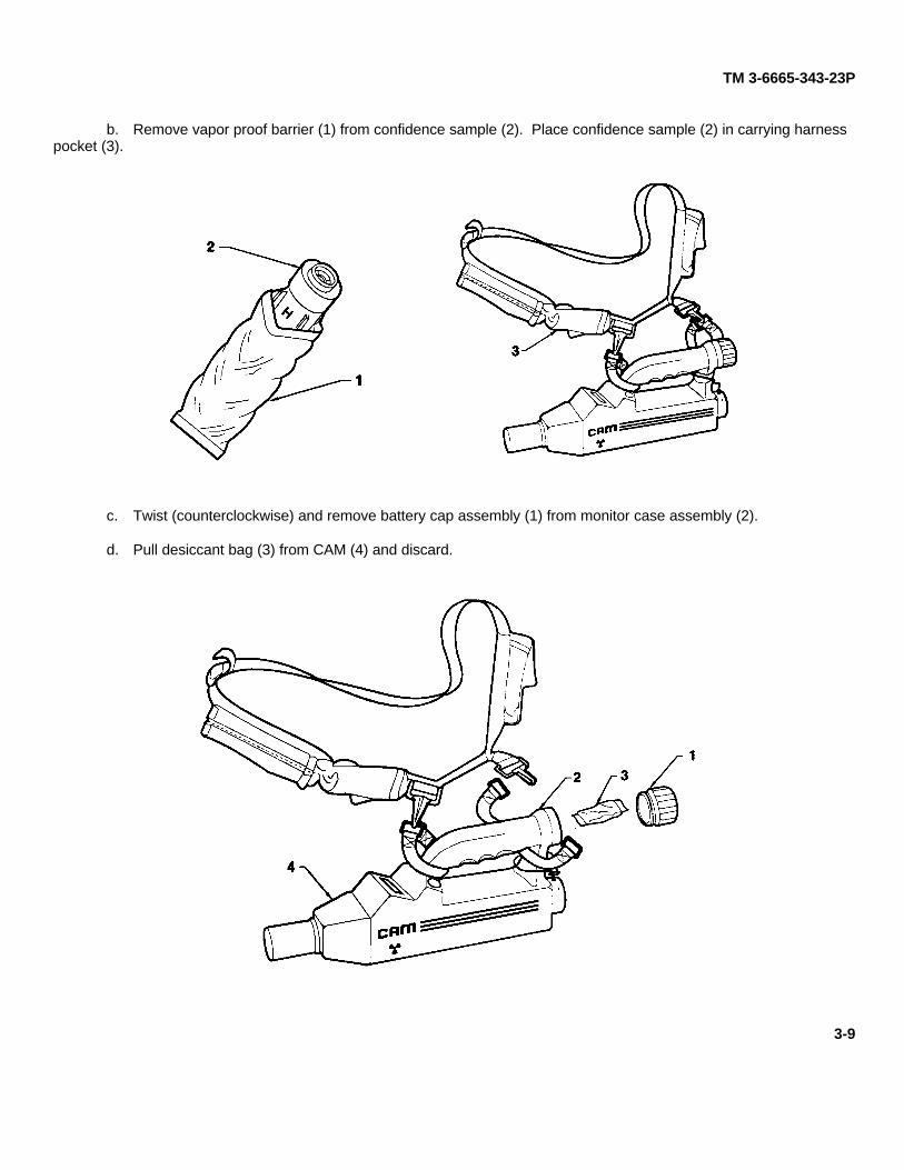
b. Remove vapor proof barrier (1) from confidence sample (2). Place confidence sample (2) in carrying harnesspocket (3).
c. Twist (counterclockwise) and remove battery cap assembly (1) from monitor case assembly (2).
d. Pull desiccant bag (3) from CAM (4) and discard.
3-9
TM 3-6665-343-23P
3-8. ASSEMBLY AND PREPARATION OF CAM FOR USE (CONT).
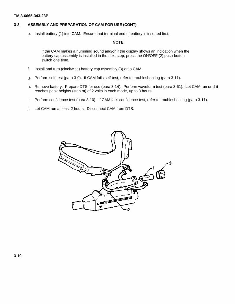
e. Install battery (1) into CAM. Ensure that terminal end of battery is inserted first.
NOTE
If the CAM makes a humming sound and/or if the display shows an indication when thebattery cap assembly is installed in the next step, press the ON/OFF (2) push-buttonswitch one time.
f. Install and turn (clockwise) battery cap assembly (3) onto CAM.
g. Perform self-test (para 3-9). If CAM fails self-test, refer to troubleshooting (para 3-11).
h. Remove battery. Prepare DTS for use (para 3-14). Perform waveform test (para 3-61). Let CAM run until itreaches peak heights (step m) of 2 volts in each mode, up to 8 hours.
i. Perform confidence test (para 3-10). If CAM fails confidence test, refer to troubleshooting (para 3-11).
j. Let CAM run at least 2 hours. Disconnect CAM from DTS.
3-10
TM 3-6665-343-23P
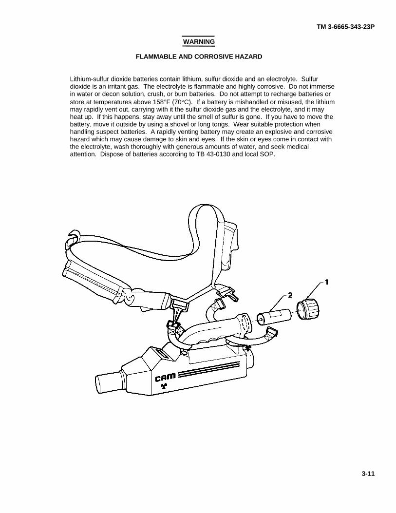
WARNING
FLAMMABLE AND CORROSIVE HAZARD
Lithium-sulfur dioxide batteries contain lithium, sulfur dioxide and an electrolyte. Sulfurdioxide is an irritant gas. The electrolyte is flammable and highly corrosive. Do not immersein water or decon solution, crush, or burn batteries. Do not attempt to recharge batteries orstore at temperatures above 158°F (70°C). If a battery is mishandled or misused, the lithiummay rapidly vent out, carrying with it the sulfur dioxide gas and the electrolyte, and it mayheat up. If this happens, stay away until the smell of sulfur is gone. If you have to move thebattery, move it outside by using a shovel or long tongs. Wear suitable protection whenhandling suspect batteries. A rapidly venting battery may create an explosive and corrosivehazard which may cause damage to skin and eyes. If the skin or eyes come in contact withthe electrolyte, wash thoroughly with generous amounts of water, and seek medicalattention. Dispose of batteries according to TB 43-0130 and local SOP.
3-11
TM 3-6665-343-23P
3-8. ASSEMBLY AND PREPARATION OF CAM FOR USE (CONT).
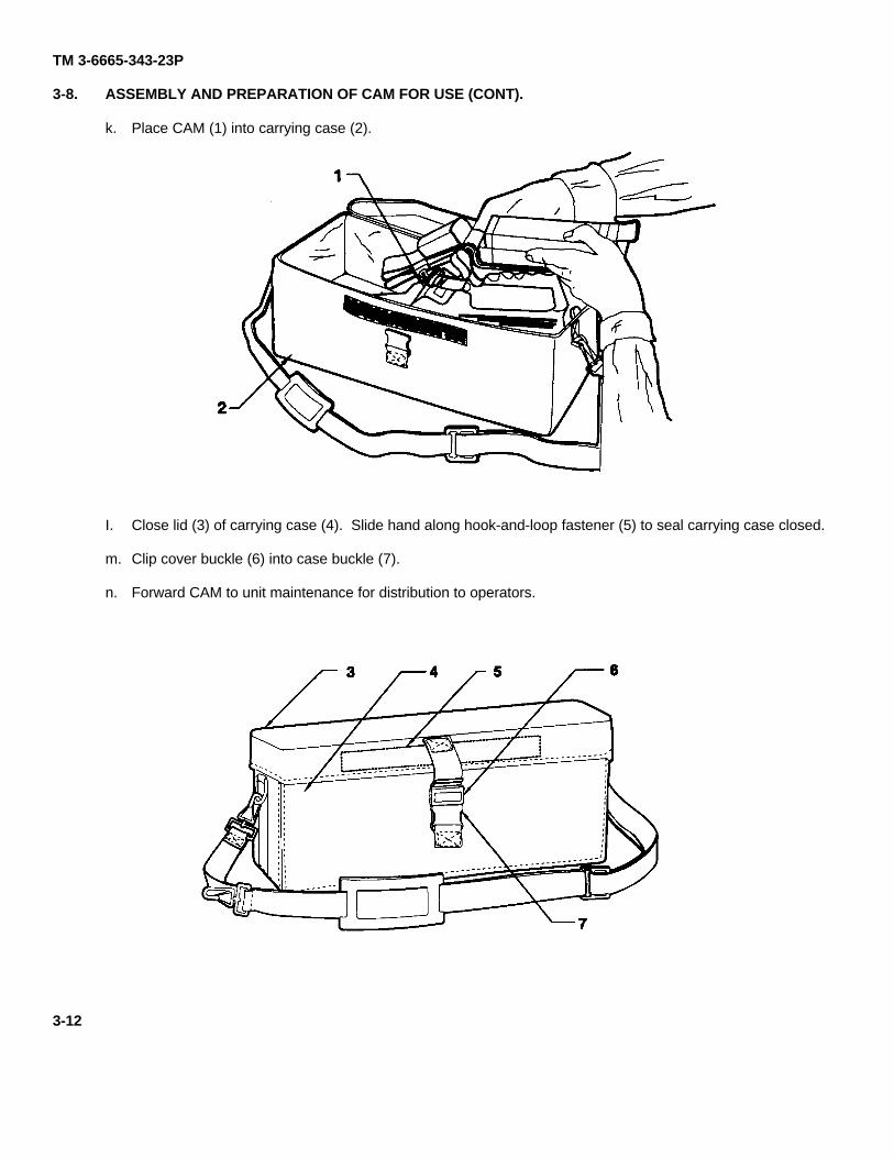
k. Place CAM (1) into carrying case (2).
I. Close lid (3) of carrying case (4). Slide hand along hook-and-loop fastener (5) to seal carrying case closed.
m. Clip cover buckle (6) into case buckle (7).
n. Forward CAM to unit maintenance for distribution to operators.
3-12
TM 3-6665-343-23P
3-9. SELF-TEST.
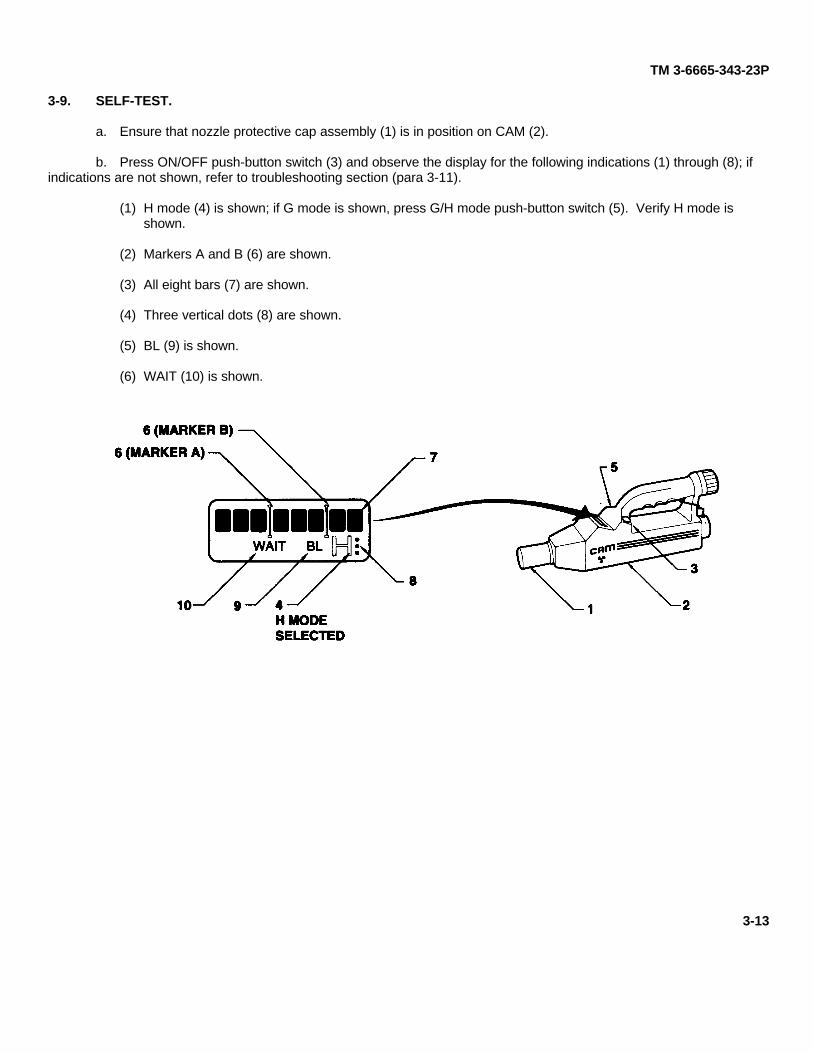
a. Ensure that nozzle protective cap assembly (1) is in position on CAM (2).
b. Press ON/OFF push-button switch (3) and observe the display for the following indications (1) through (8); ifindications are not shown, refer to troubleshooting section (para 3-11).
(1) H mode (4) is shown; if G mode is shown, press G/H mode push-button switch (5). Verify H mode isshown.
(2) Markers A and B (6) are shown.
(3) All eight bars (7) are shown.
(4) Three vertical dots (8) are shown.
(5) BL (9) is shown.
(6) WAIT (10) is shown.
3-13
TM 3-6665-343-23P
3-9. SELF-TEST (CONT).
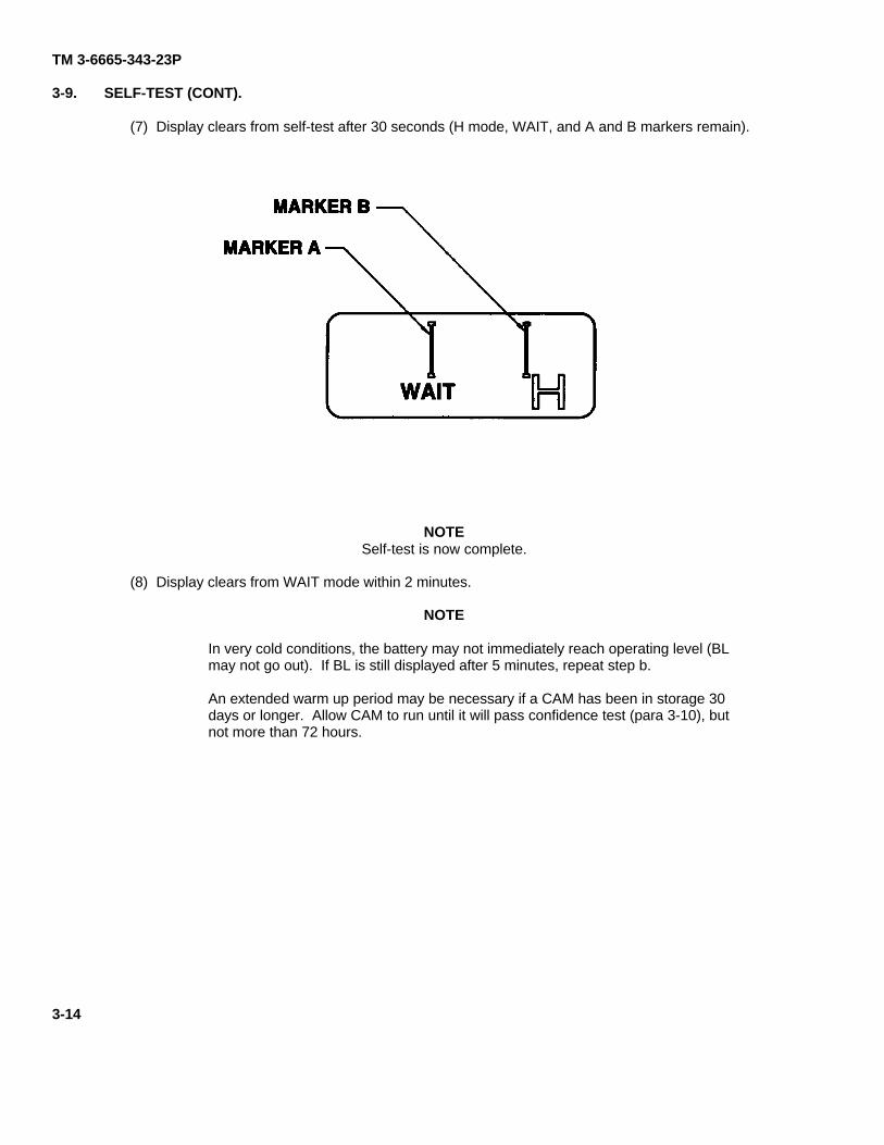
(7) Display clears from self-test after 30 seconds (H mode, WAIT, and A and B markers remain).
NOTESelf-test is now complete.
(8) Display clears from WAIT mode within 2 minutes.
NOTE
In very cold conditions, the battery may not immediately reach operating level (BLmay not go out). If BL is still displayed after 5 minutes, repeat step b.
An extended warm up period may be necessary if a CAM has been in storage 30days or longer. Allow CAM to run until it will pass confidence test (para 3-10), butnot more than 72 hours.
3-14
TM 3-6665-343-23P
3-10. CONFIDENCE TEST.
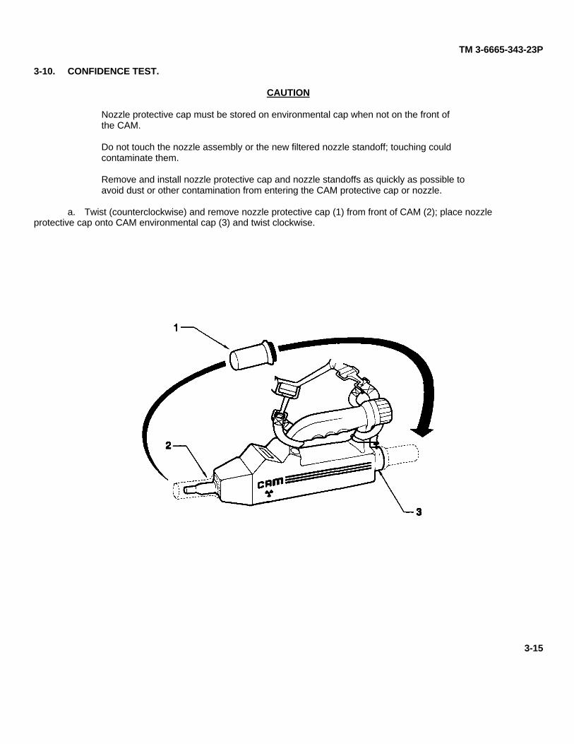
CAUTION
Nozzle protective cap must be stored on environmental cap when not on the front ofthe CAM.
Do not touch the nozzle assembly or the new filtered nozzle standoff; touching couldcontaminate them.
Remove and install nozzle protective cap and nozzle standoffs as quickly as possible toavoid dust or other contamination from entering the CAM protective cap or nozzle.
a. Twist (counterclockwise) and remove nozzle protective cap (1) from front of CAM (2); place nozzleprotective cap onto CAM environmental cap (3) and twist clockwise.
3-15
TM 3-6665-343-23P
3-10. CONFIDENCE TEST (CONT).
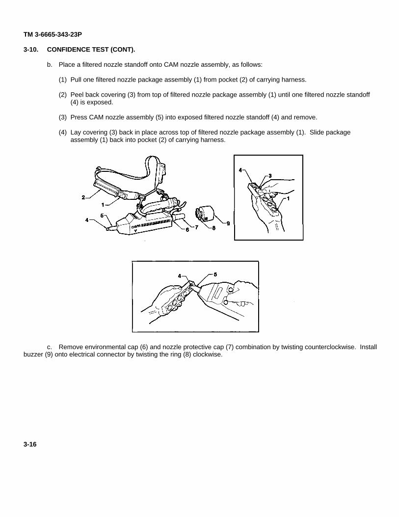
b. Place a filtered nozzle standoff onto CAM nozzle assembly, as follows:
(1) Pull one filtered nozzle package assembly (1) from pocket (2) of carrying harness.
(2) Peel back covering (3) from top of filtered nozzle package assembly (1) until one filtered nozzle standoff(4) is exposed.
(3) Press CAM nozzle assembly (5) into exposed filtered nozzle standoff (4) and remove.
(4) Lay covering (3) back in place across top of filtered nozzle package assembly (1). Slide packageassembly (1) back into pocket (2) of carrying harness.
c. Remove environmental cap (6) and nozzle protective cap (7) combination by twisting counterclockwise. Installbuzzer (9) onto electrical connector by twisting the ring (8) clockwise.
3-16
TM 3-6665-343-23P
NOTE
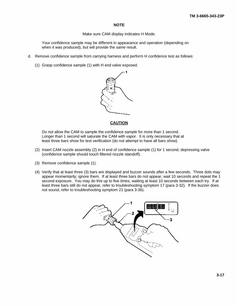
Make sure CAM display indicates H Mode.
Your confidence sample may be different in appearance and operation (depending onwhen it was produced), but will provide the same result.
d. Remove confidence sample from carrying harness and perform H confidence test as follows:
(1) Grasp confidence sample (1) with H end valve exposed.
CAUTION
Do not allow the CAM to sample the confidence sample for more than 1 second.Longer than 1 second will saturate the CAM with vapor. It is only necessary that atleast three bars show for test verification (do not attempt to have all bars show).
(2) Insert CAM nozzle assembly (2) in H end of confidence sample (1) for 1 second, depressing valve(confidence sample should touch filtered nozzle standoff).
(3) Remove confidence sample (1).
(4) Verify that at least three (3) bars are displayed and buzzer sounds after a few seconds. Three dots mayappear momentarily; ignore them. If at least three bars do not appear, wait 10 seconds and repeat the 1second exposure. You may do this up to five times, waiting at least 10 seconds between each try. If atleast three bars still do not appear, refer to troubleshooting symptom 17 (para 3-32). If the buzzer doesnot sound, refer to troubleshooting symptom 21 (para 3-36).
3-17
TM 3-6665-343-23P
3-10. CONFIDENCE TEST (CONT).
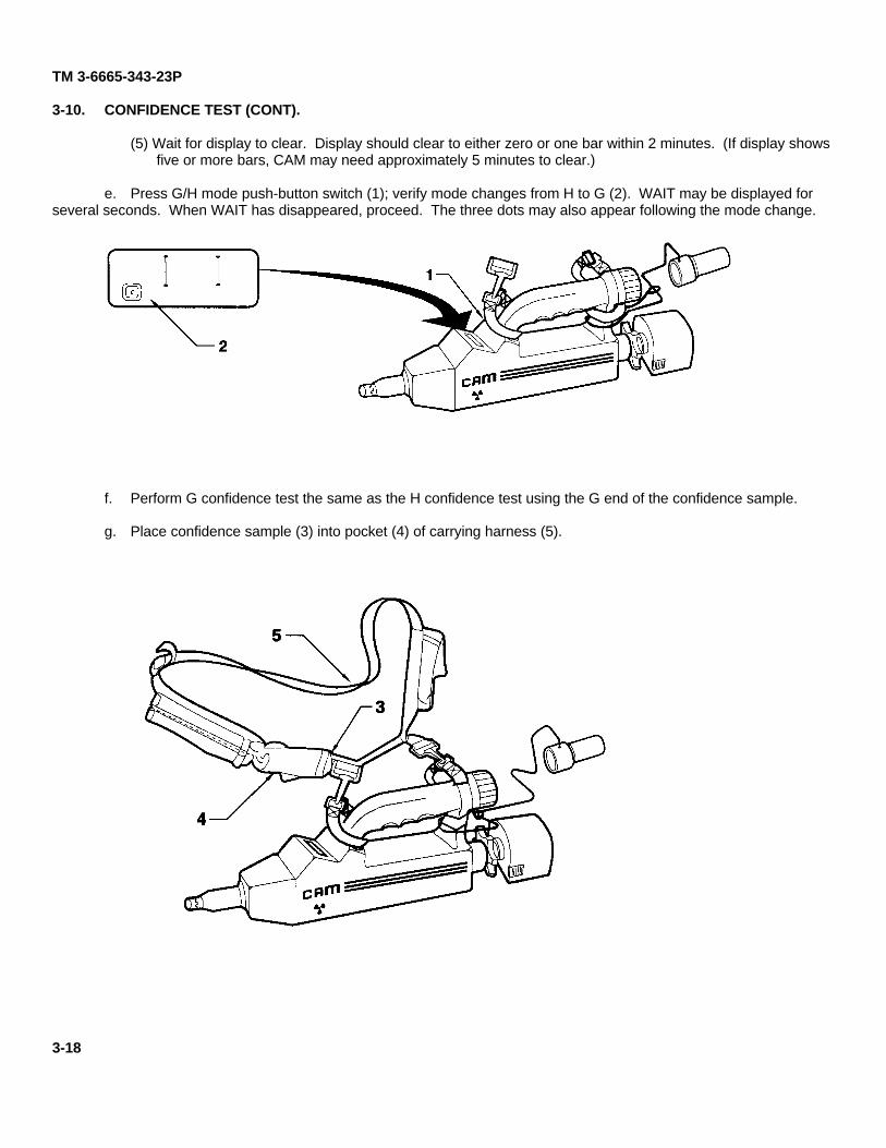
(5) Wait for display to clear. Display should clear to either zero or one bar within 2 minutes. (If display showsfive or more bars, CAM may need approximately 5 minutes to clear.)
e. Press G/H mode push-button switch (1); verify mode changes from H to G (2). WAIT may be displayed forseveral seconds. When WAIT has disappeared, proceed. The three dots may also appear following the mode change.
f. Perform G confidence test the same as the H confidence test using the G end of the confidence sample.
g. Place confidence sample (3) into pocket (4) of carrying harness (5).
3-18
TM 3-6665-343-23P
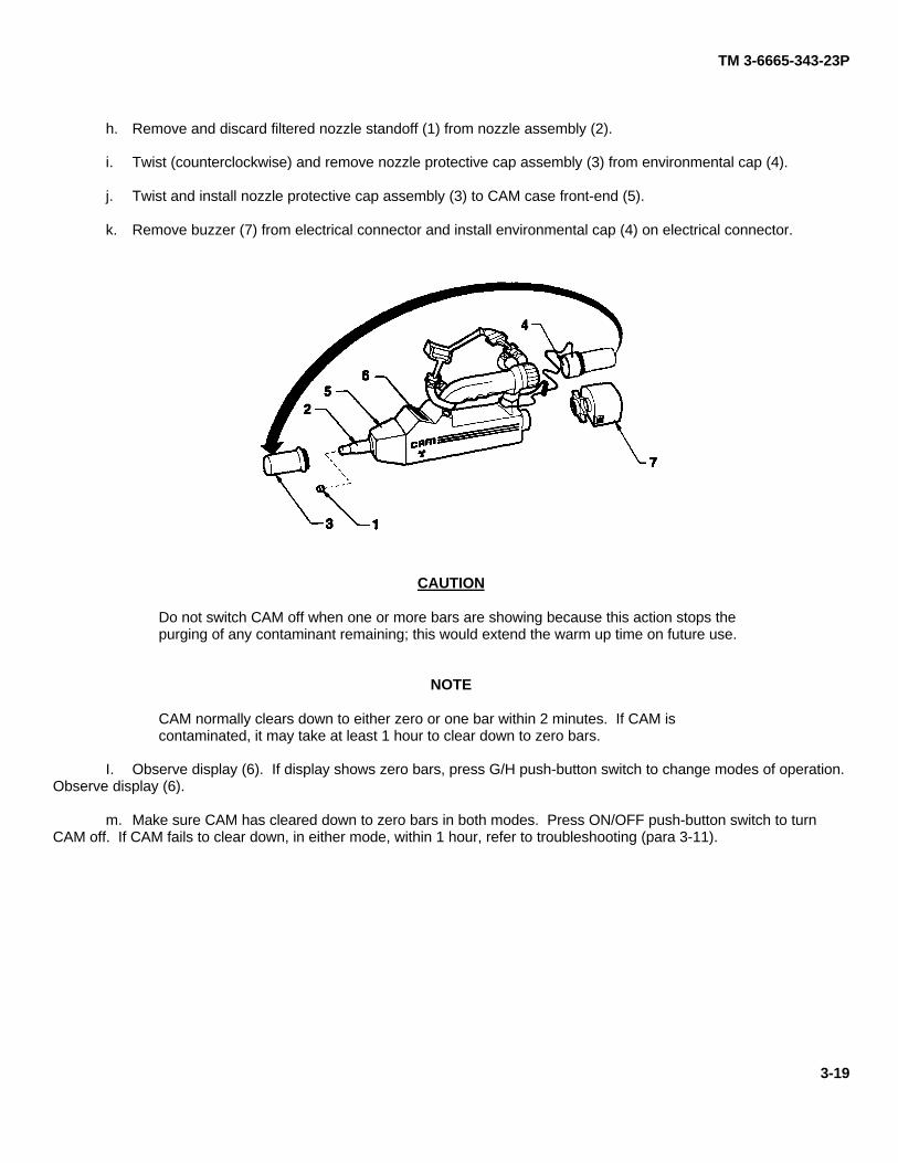
h. Remove and discard filtered nozzle standoff (1) from nozzle assembly (2).
i. Twist (counterclockwise) and remove nozzle protective cap assembly (3) from environmental cap (4).
j. Twist and install nozzle protective cap assembly (3) to CAM case front-end (5).
k. Remove buzzer (7) from electrical connector and install environmental cap (4) on electrical connector.
CAUTION
Do not switch CAM off when one or more bars are showing because this action stops thepurging of any contaminant remaining; this would extend the warm up time on future use.
NOTE
CAM normally clears down to either zero or one bar within 2 minutes. If CAM iscontaminated, it may take at least 1 hour to clear down to zero bars.
I. Observe display (6). If display shows zero bars, press G/H push-button switch to change modes of operation.Observe display (6).
m. Make sure CAM has cleared down to zero bars in both modes. Press ON/OFF push-button switch to turnCAM off. If CAM fails to clear down, in either mode, within 1 hour, refer to troubleshooting (para 3-11).
3-19
TM 3-6665-343-23P
Section III. DIRECT SUPPORT TROUBLESHOOTING
3-11. INTRODUCTION.
WARNING
RADIATION HAZARD
NICKEL-63 (NI-63)
Wipe test must be performed before and after any maintenance or testing of CAM.
When a CAM is sent to DS for repair, the performance of the CAM is first checked by an operational check. Whena fault occurs during the operational check, the maintainer goes to the troubleshooting logic tree for the symptom of thefault.
The troubleshooting logic tree leads the maintainer through step-by-step procedures to determine that there is amalfunction and then to isolate the trouble to the malfunctioning assembly or part. The logic tree will reference tests andmaintenance procedures (in section IV) where needed. At any point during the referenced tests that the indications arenot as required, the maintainer returns to the logic tree. The logic tree will tell the maintainer what to do if the test hasfailed.
Once the CAM has been repaired, it is again checked by the operational check to determine that the CAM is readyfor a mission.
3-20
TM 3-6665-343-23P
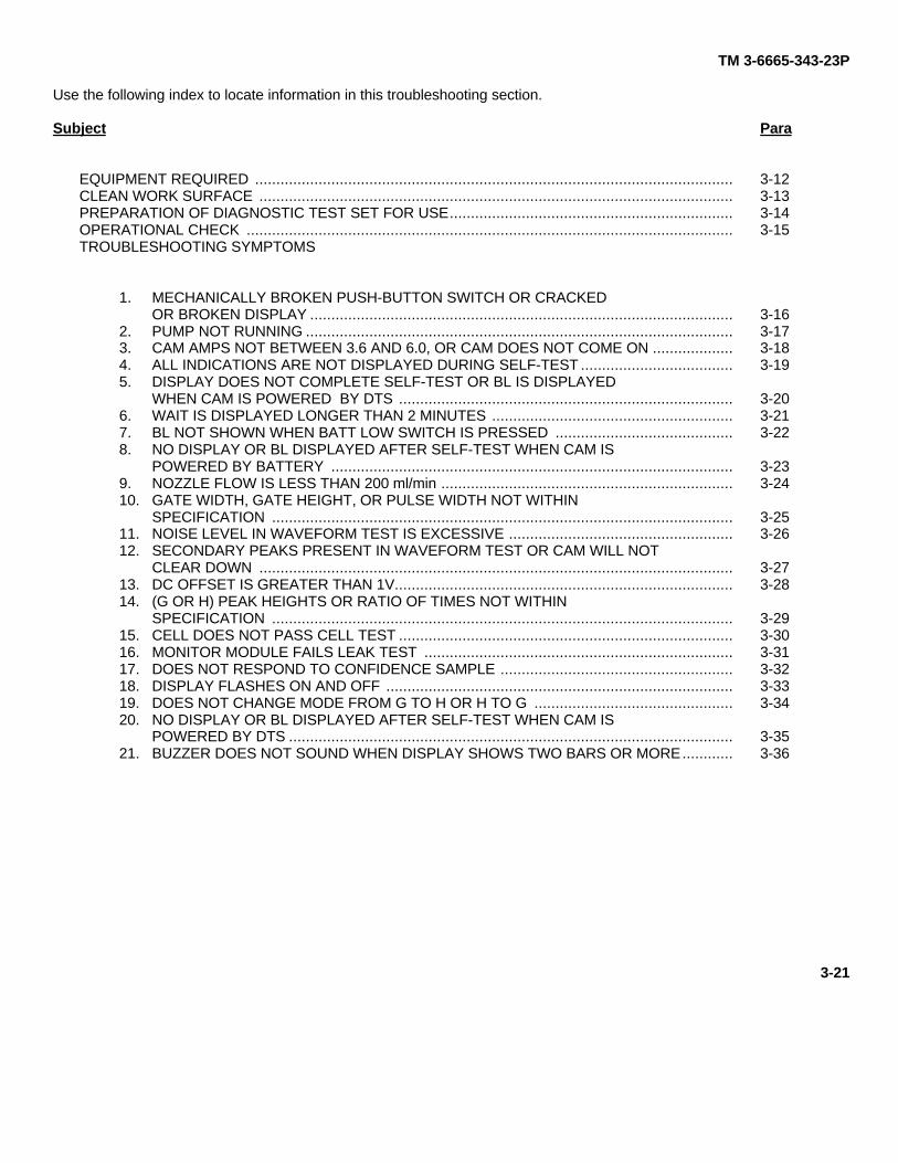
Use the following index to locate information in this troubleshooting section.
Subject
EQUIPMENT REQUIRED .................................................................................................................CLEAN WORK SURFACE ................................................................................................................PREPARATION OF DIAGNOSTIC TEST SET FOR USE...................................................................OPERATIONAL CHECK ...................................................................................................................TROUBLESHOOTING SYMPTOMS
1. MECHANICALLY BROKEN PUSH-BUTTON SWITCH OR CRACKEDOR BROKEN DISPLAY ....................................................................................................
2. PUMP NOT RUNNING .....................................................................................................3. CAM AMPS NOT BETWEEN 3.6 AND 6.0, OR CAM DOES NOT COME ON ...................4. ALL INDICATIONS ARE NOT DISPLAYED DURING SELF-TEST ....................................5. DISPLAY DOES NOT COMPLETE SELF-TEST OR BL IS DISPLAYED
WHEN CAM IS POWERED BY DTS ...............................................................................6. WAIT IS DISPLAYED LONGER THAN 2 MINUTES .........................................................7. BL NOT SHOWN WHEN BATT LOW SWITCH IS PRESSED ..........................................8. NO DISPLAY OR BL DISPLAYED AFTER SELF-TEST WHEN CAM IS
POWERED BY BATTERY ...............................................................................................9. NOZZLE FLOW IS LESS THAN 200 ml/min .....................................................................10. GATE WIDTH, GATE HEIGHT, OR PULSE WIDTH NOT WITHIN
SPECIFICATION .............................................................................................................11. NOISE LEVEL IN WAVEFORM TEST IS EXCESSIVE .....................................................12. SECONDARY PEAKS PRESENT IN WAVEFORM TEST OR CAM WILL NOT
CLEAR DOWN ................................................................................................................13. DC OFFSET IS GREATER THAN 1V................................................................................14. (G OR H) PEAK HEIGHTS OR RATIO OF TIMES NOT WITHIN
SPECIFICATION .............................................................................................................15. CELL DOES NOT PASS CELL TEST ...............................................................................16. MONITOR MODULE FAILS LEAK TEST .........................................................................17. DOES NOT RESPOND TO CONFIDENCE SAMPLE .......................................................18. DISPLAY FLASHES ON AND OFF ..................................................................................19. DOES NOT CHANGE MODE FROM G TO H OR H TO G ...............................................20. NO DISPLAY OR BL DISPLAYED AFTER SELF-TEST WHEN CAM IS
POWERED BY DTS .........................................................................................................21. BUZZER DOES NOT SOUND WHEN DISPLAY SHOWS TWO BARS OR MORE............
Para
3-123-133-143-15
3-163-173-183-19
3-203-213-22
3-233-24
3-253-26
3-273-28
3-293-303-313-323-333-34
3-353-36
3-21
TM 3-6665-343-23P
3-12. EQUIPMENT REQUIRED.
The following equipment is required to troubleshoot the CAM:
Tool Kit, Electronic Equipment TK-105/GOscilloscope, Dual Trace, AN/USM-488Multimeter, Digital, AN/PSM-45A (DMM)CAM Diagnostic Test SetWrench, Torque (4-120 lb in. 3/8 in. drive)Screwdriver, Torque (10-120 oz in.)AdapterSocket (30A/F 1/2 in. drive)Bit, Screwdriver (1/4 in. A/F Hex Shank, cross-tipped)Blade, Screwdriver (1/4 in. A/F Hex Shank)Bit, Screwdriver (1/4 in. A/F Hex Shank, posidrive)Power Supply
3-13. CLEAN WORK SURFACE.
Clean the work surface (Para 3-1). Place clean paper (Item 5, App D) across the top of the surface.
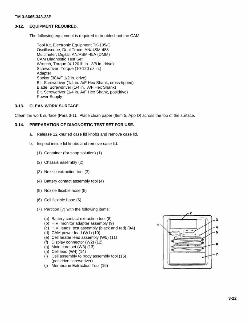
3-14. PREPARATION OF DIAGNOSTIC TEST SET FOR USE.
a. Release 12 knurled case lid knobs and remove case lid.
b. Inspect inside lid knobs and remove case lid.
(1) Container (for soap solution) (1)
(2) Chassis assembly (2)
(3) Nozzle extraction tool (3)
(4) Battery contact assembly tool (4)
(5) Nozzle flexible hose (5)
(6) Cell flexible hose (6)
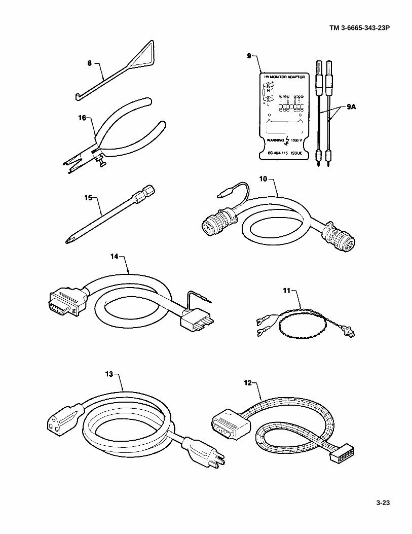
(7) Partition (7) with the following items:
(a) Battery contact extraction tool (8)(b) H.V. monitor adapter assembly (9)(c) H.V. leads, test assembly (black and red) (9A)(d) CAM power lead (W1) (10)(e) Cell heater lead assembly (W5) (11)(f) Display connector (W2) (12)(g) Main cord set (W3) (13)(h) Cell lead (W4) (14)(i) Cell assembly to body assembly tool (15)
(posidrive screwdriver)(j) Membrane Extraction Tool (16)
3-22
TM 3-6665-343-23P
3-23
TM 3-6665-343-23P
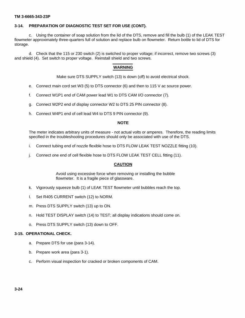
3-14. PREPARATION OF DIAGNOSTIC TEST SET FOR USE (CONT).
c. Using the container of soap solution from the lid of the DTS, remove and fill the bulb (1) of the LEAK TESTflowmeter approximately three-quarters full of solution and replace bulb on flowmeter. Return bottle to lid of DTS forstorage.
d. Check that the 115 or 230 switch (2) is switched to proper voltage; if incorrect, remove two screws (3)and shield (4). Set switch to proper voltage. Reinstall shield and two screws.
WARNING
Make sure DTS SUPPLY switch (13) is down (off) to avoid electrical shock.
e. Connect main cord set W3 (5) to DTS connector (6) and then to 115 V ac source power.
f. Connect W1P1 end of CAM power lead W1 to DTS CAM I/O connector (7).
g. Connect W2P2 end of display connector W2 to DTS 25 PIN connector (8).
h. Connect W4P1 end of cell lead W4 to DTS 9 PIN connector (9).
NOTE
The meter indicates arbitrary units of measure - not actual volts or amperes. Therefore, the reading limitsspecified in the troubleshooting procedures should only be associated with use of the DTS.
i. Connect tubing end of nozzle flexible hose to DTS FLOW LEAK TEST NOZZLE fitting (10).
j. Connect one end of cell flexible hose to DTS FLOW LEAK TEST CELL fitting (11).
CAUTION
Avoid using excessive force when removing or installing the bubbleflowmeter. It is a fragile piece of glassware.
k. Vigorously squeeze bulb (1) of LEAK TEST flowmeter until bubbles reach the top.
I. Set R405 CURRENT switch (12) to NORM.
m. Press DTS SUPPLY switch (13) up to ON.
n. Hold TEST DISPLAY switch (14) to TEST; all display indications should come on.
o. Press DTS SUPPLY switch (13) down to OFF.
3-15. OPERATIONAL CHECK.
a. Prepare DTS for use (para 3-14).
b. Prepare work area (para 3-1).
c. Perform visual inspection for cracked or broken components of CAM.
3-24
TM 3-6665-343-23P
3-25
TM 3-6665-343-23P
3-15. OPERATIONAL CHECK (CONT).
d. Remove CAM environmental cap assembly; let it hang on the tether.
e. Remove battery cap assembly. Ensure battery is removed. Reinstall battery cap assembly.
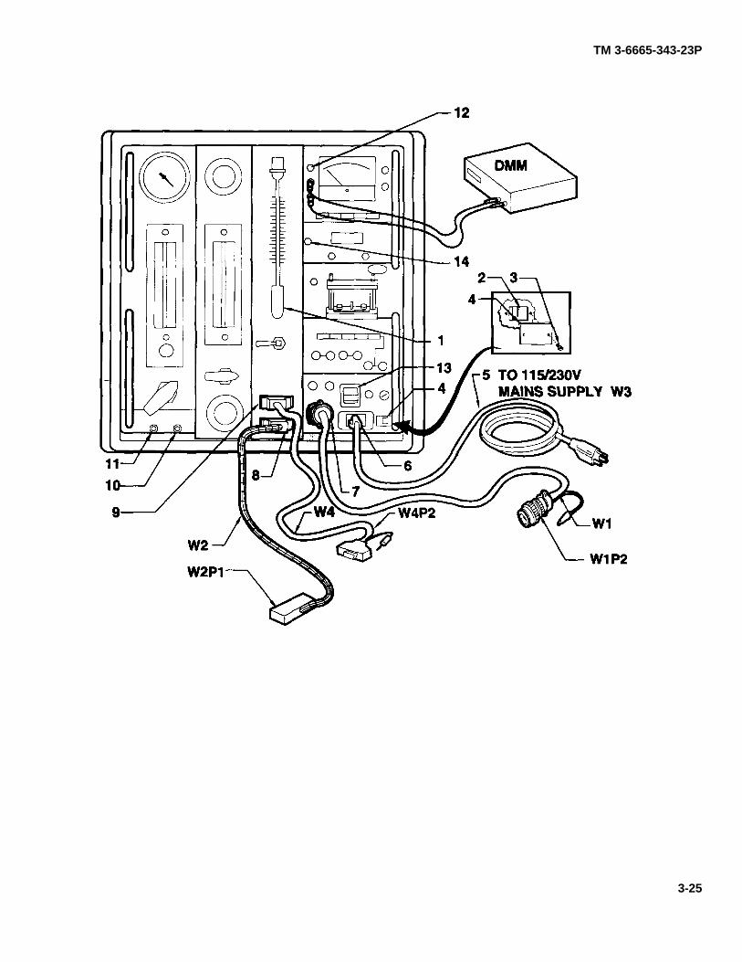
f. Connect W1P2 to CAM connector assembly.
NOTE
The CAM is protected from excessive current draw by the DTS automatic powershut off. To reset the DTS, press the supply switch off and then on again.
g. Press DTS SUPPLY switch (1) up to ON; SUPPLY indicator lamp comes on. If CAM does not come on, pressCAM ON/OFF push-button switch.
h. Listen for pump running. If pump is not running, perform troubleshooting symptom 2 (para 3-17).
i. On DTS, press CAM AMP switch (2).
j. DTS meter should indicate 3.6 to 6.0 units. If DTS meter does not indicate 3.6 to 6.0 units, performtroubleshooting symptom 3 (para 3-18).
k. Press CAM ON/OFF push-button switch to turn CAM off. Wait 2 seconds. Press ON/OFF push-button switchagain to start CAM in self-test.
I. Monitor CAM display for the following indications:
(1) All eight bars are shown.
(2) Markers A and B are shown.
(3) Three vertical dots are shown.
(4) BL is shown.
(5) WAIT is shown.
(6) H or G is shown.
(7) If above 6 steps are not indicated, perform troubleshooting symptom 4 (para 3-19).
(8) The display partially clears after 30 seconds; H or G, A and B markers, and WAIT remain.
(9) After completion of self-test, press G/H push-button; opposite indication of step 6 above is shown. WAITshould clear within 2 minutes. If it does not clear within 2 minutes, perform troubleshooting symptom 6(para 3-21).
NOTE
Disregard any bars that may reappear on CAM display for purposes of this test.
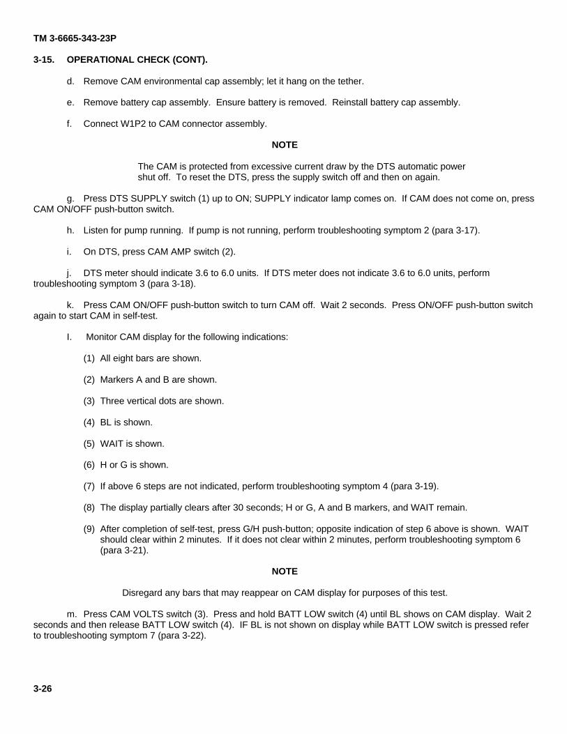
m. Press CAM VOLTS switch (3). Press and hold BATT LOW switch (4) until BL shows on CAM display. Wait 2seconds and then release BATT LOW switch (4). IF BL is not shown on display while BATT LOW switch is pressed referto troubleshooting symptom 7 (para 3-22).
3-26
TM 3-6665-343-23P
NOTE
If testing a monitor module assembly, proceed to step w.
n. Press CAM ON/OFF push-button switch to turn CAM off.
o. Disconnect CAM power lead W1 from CAM connector assembly.
p. Install battery into CAM.
q. Press CAM ON/OFF switch to turn CAM on, if necessary. CAM should complete self-test and BL should notremain lit. If CAM display does not light or BL remains lit after self test refer to troubleshooting symptom 8 (para 3-23).
r. Press CAM ON/OFF switch to turn CAM off.
s. Remove battery from CAM.
t. Connect DTS CAM power lead W1 to CAM connector assembly.
u. On DTS, set V2 (5) to NOZZLE INLET FLOW. Let CAM continue to run.
3-27
TM 3-6665-343-23P
3-15. OPERATIONAL CHECK (CONT).
NOTE
Remove and install nozzle protective cap as quickly as possible to avoid dust or othercontamination from entering CAM protective cap.
v. Twist (counterclockwise) and remove nozzle protective cap assembly from front of CAM; place nozzleprotective cap assembly onto CAM environmental cap and twist clockwise.
w. Push nozzle end of nozzle flexible hose over CAM nozzle assembly.
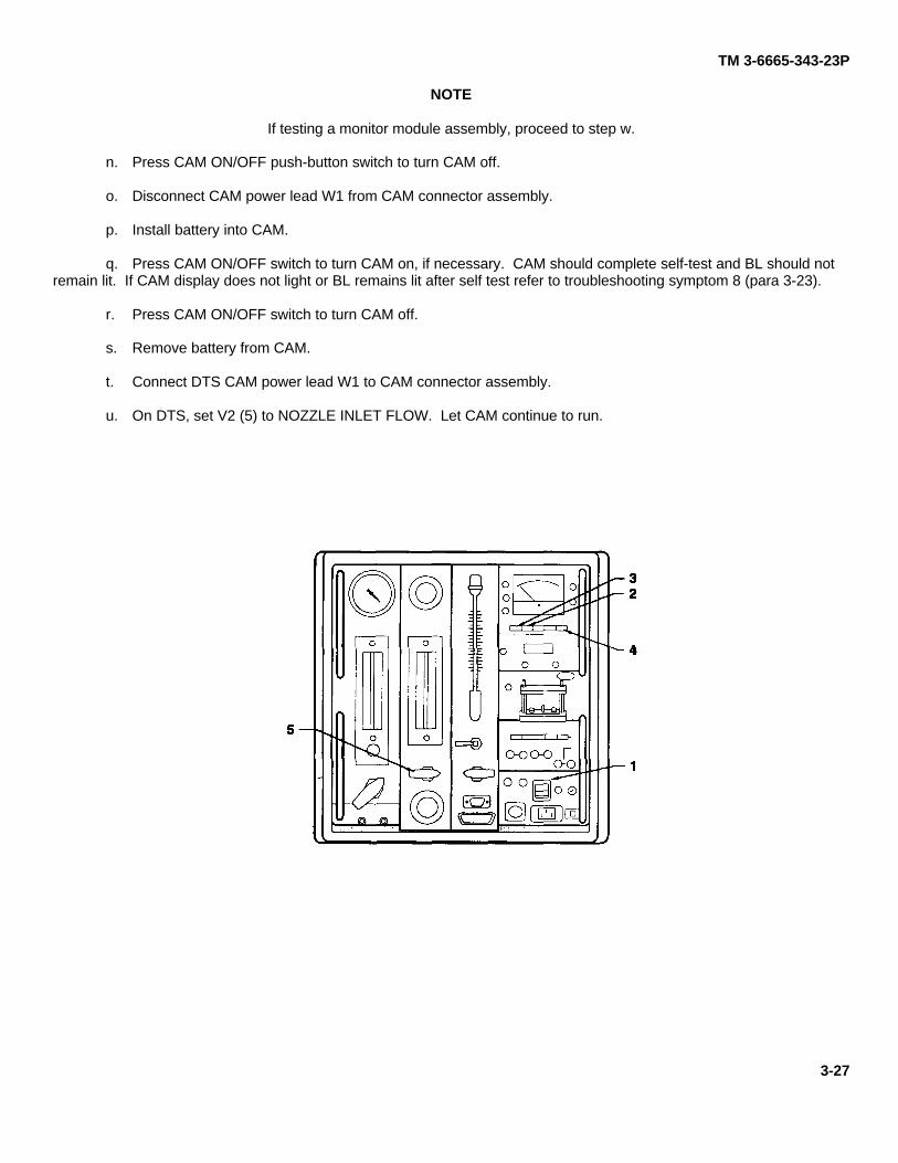
x. Read FLOW 2 flowmeter. Reading should be greater than 200 (ml/min). Read flowmeter across top of float.If reading is less than 200, perform troubleshooting symptom 9 (para 3-24).
y. Remove nozzle flexible hose from CAM nozzle assembly. Twist (counterclockwise) and remove nozzleprotective cap assembly from CAM environmental cap; place nozzle protective cap assembly onto front of CAM and twistclockwise.
z. Perform waveform test (para 3-61). When a symptom occurs, refer to the appropriate troubleshootingprocedure (para 3-11).
aa. Perform confidence test (para 3-10).
ab. Tun off DTS. Remove I/O cable W1 from CAM. Install environmental cap.
ac. Perform wipe test (para 3-7) upon completion of all maintenance, before CAM is returned to user.
ad. Remove DTS from use.
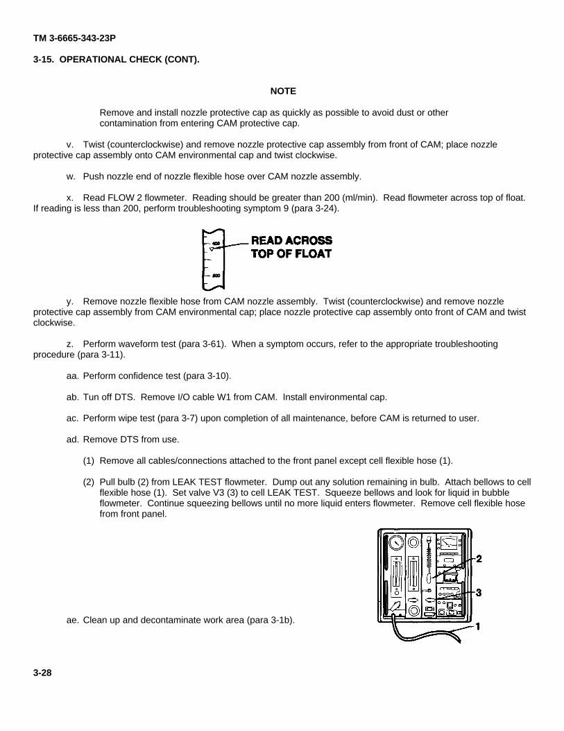
(1) Remove all cables/connections attached to the front panel except cell flexible hose (1).
(2) Pull bulb (2) from LEAK TEST flowmeter. Dump out any solution remaining in bulb. Attach bellows to cellflexible hose (1). Set valve V3 (3) to cell LEAK TEST. Squeeze bellows and look for liquid in bubbleflowmeter. Continue squeezing bellows until no more liquid enters flowmeter. Remove cell flexible hosefrom front panel.
ae. Clean up and decontaminate work area (para 3-1b).
3-28
TM 3-6665-343-23P
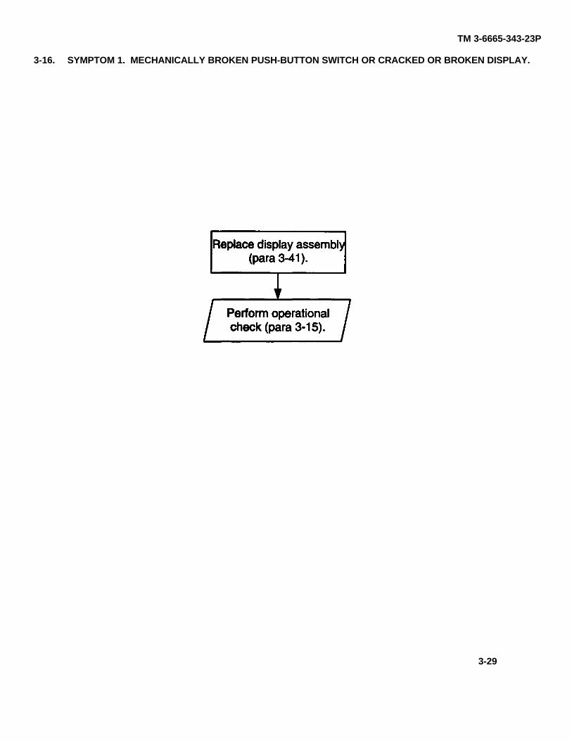
3-16. SYMPTOM 1. MECHANICALLY BROKEN PUSH-BUTTON SWITCH OR CRACKED OR BROKEN DISPLAY.
para 3-15
para 3-41
3-29
TM 3-6665-343-23P
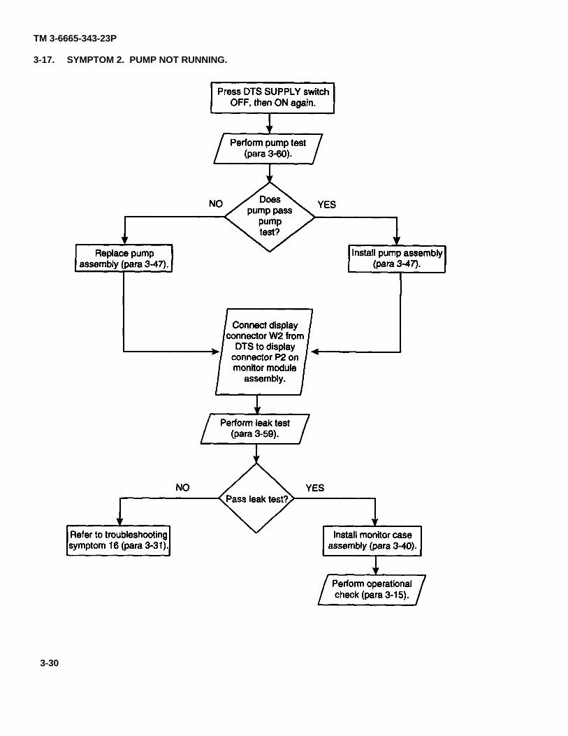
3-17. SYMPTOM 2. PUMP NOT RUNNING.
para 3-59
para 3-47para 3-47
para 3-60
para 3-15
para 3-40para 3-31
3-30
TM 3-6665-343-23P
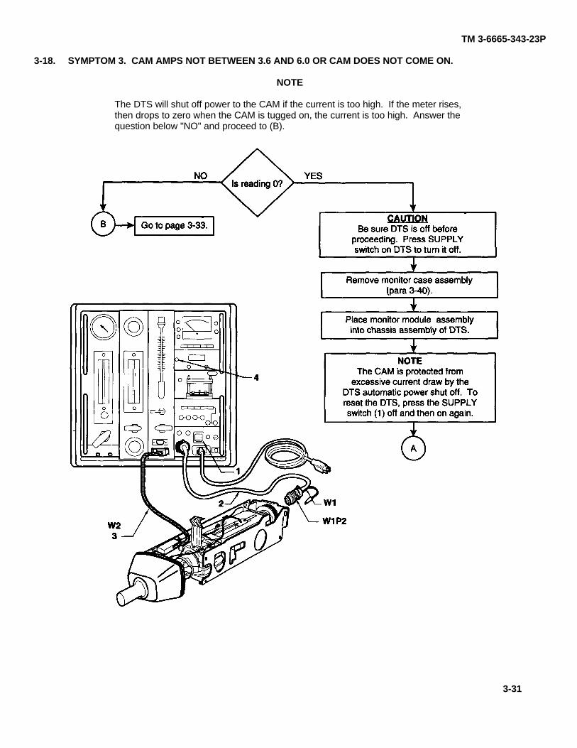
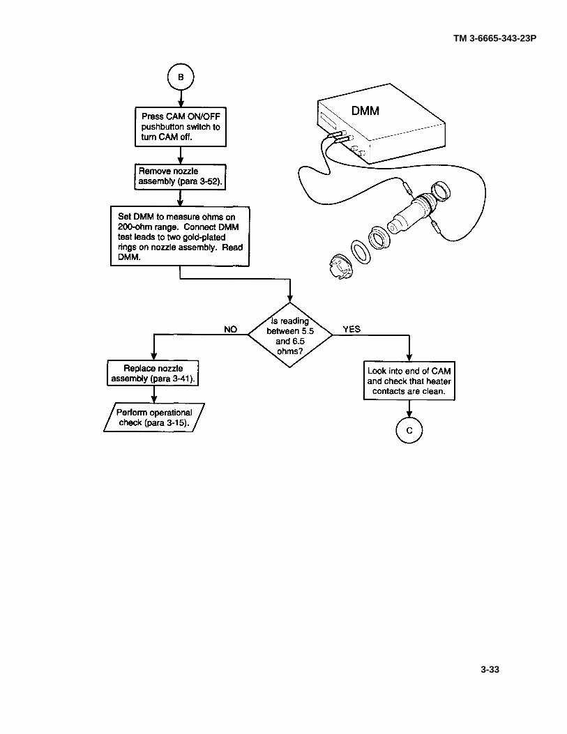
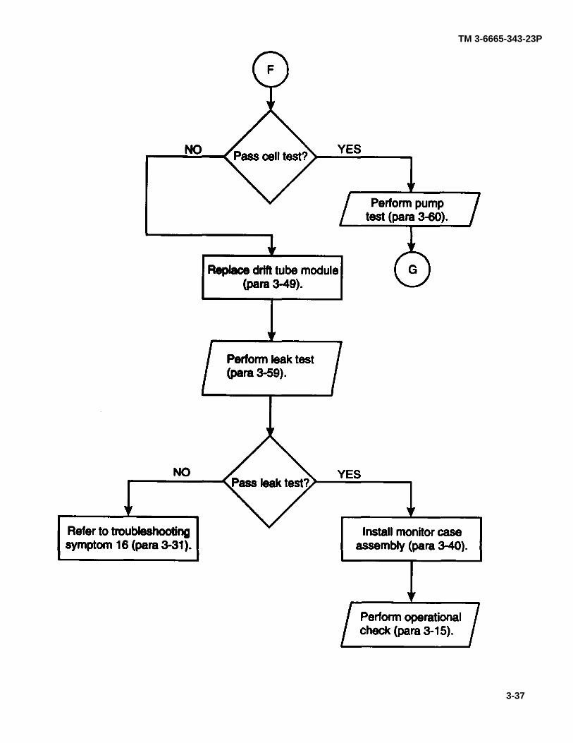
3-18. SYMPTOM 3. CAM AMPS NOT BETWEEN 3.6 AND 6.0 OR CAM DOES NOT COME ON.
NOTE
The DTS will shut off power to the CAM if the current is too high. If the meter rises,then drops to zero when the CAM is tugged on, the current is too high. Answer thequestion below "NO" and proceed to (B).
para 3-40
page 3-33
3-31
TM 3-6665-343-23P
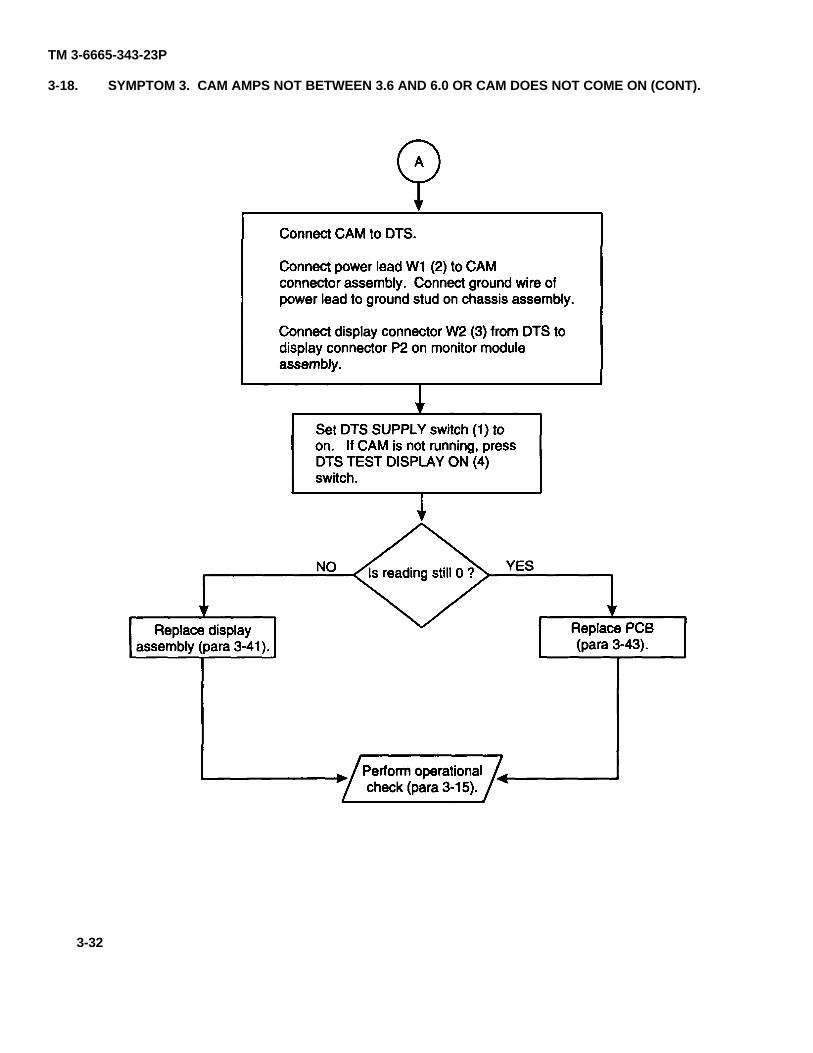
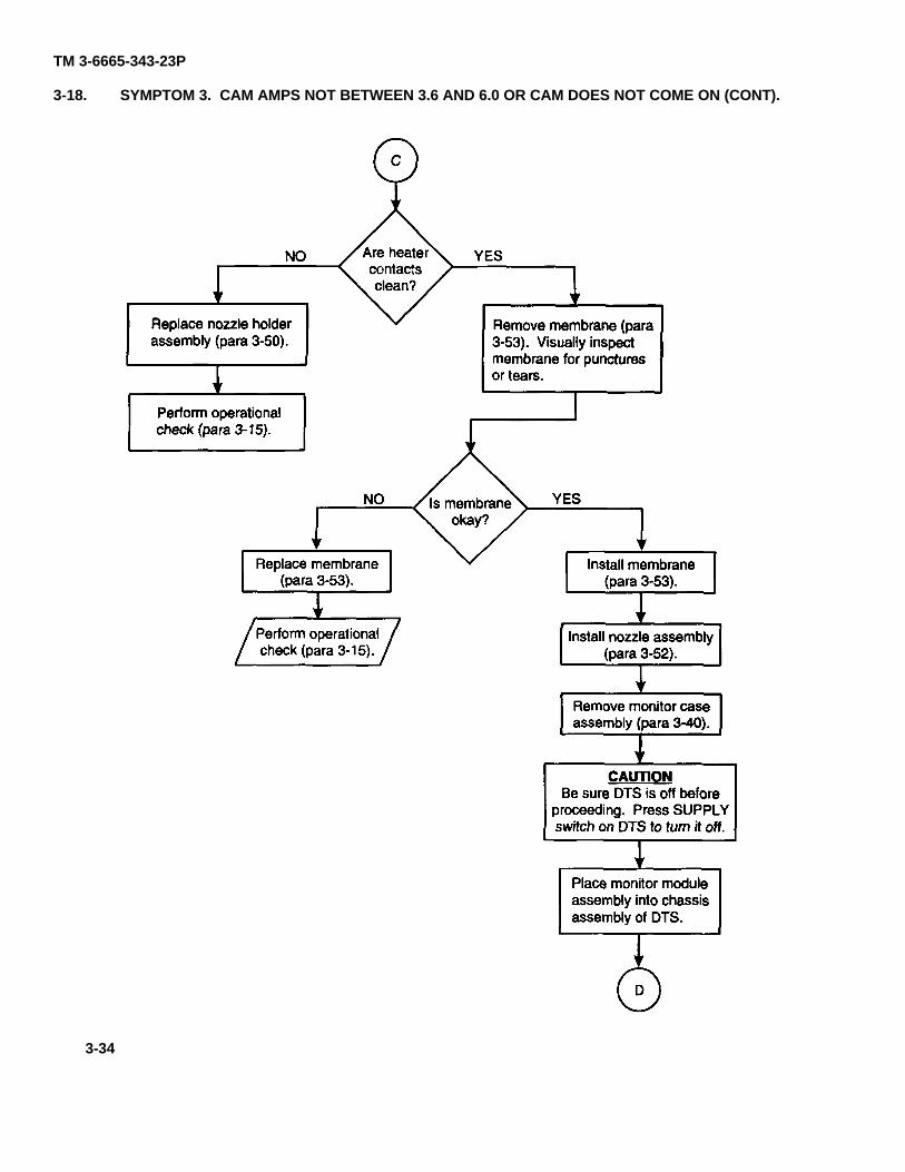
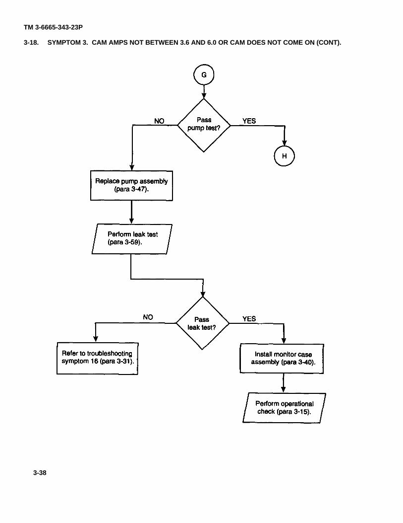
3-18. SYMPTOM 3. CAM AMPS NOT BETWEEN 3.6 AND 6.0 OR CAM DOES NOT COME ON (CONT).
para 3-15
para 3-43para 3-41
3-32
TM 3-6665-343-23P
para 3-15
para 3-41
para 3-52
3-33
TM 3-6665-343-23P
3-18. SYMPTOM 3. CAM AMPS NOT BETWEEN 3.6 AND 6.0 OR CAM DOES NOT COME ON (CONT).
para 3-53
para 3-52
para 3-40
para 3-15
para 3-53
para 3-15
para 3-53para 3-50
3-34
TM 3-6665-343-23P
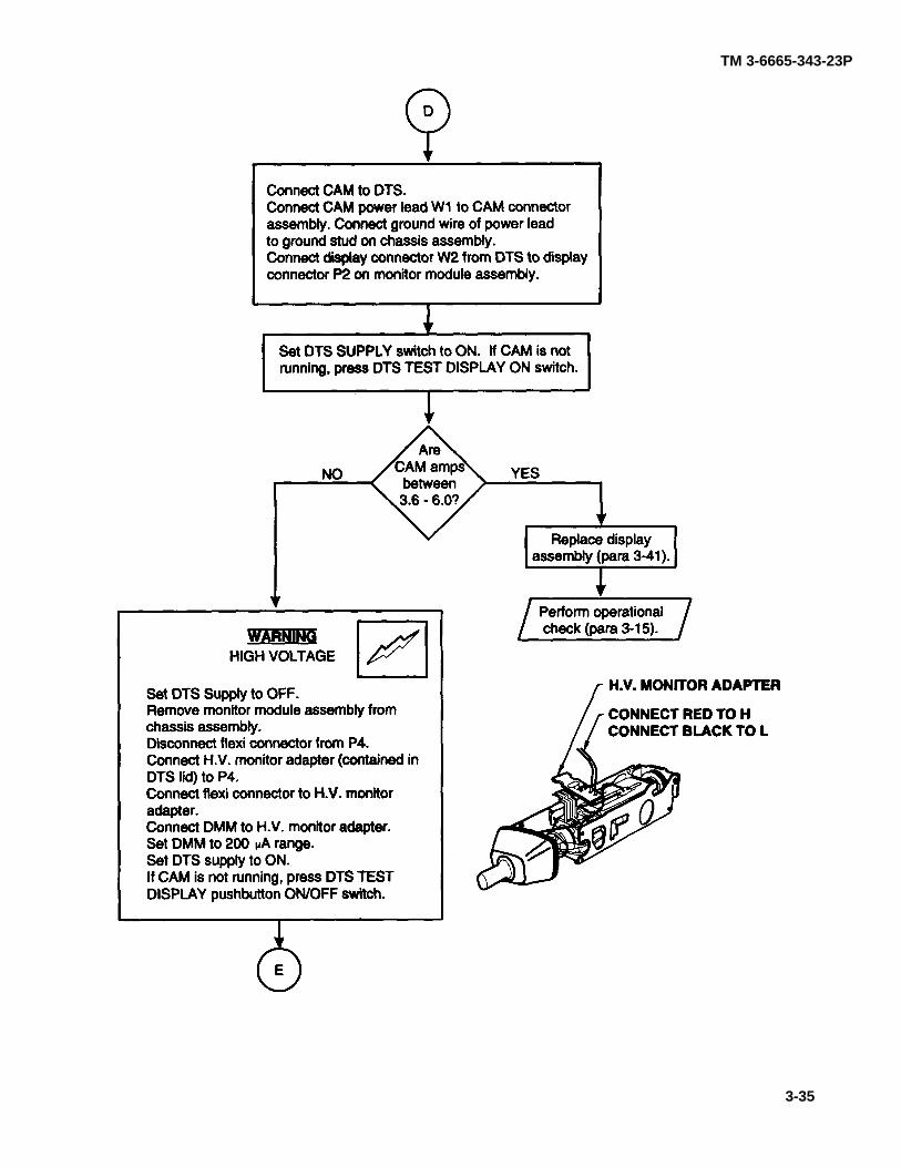
para 3-41
para 3-15
3-35
TM 3-6665-343-23P
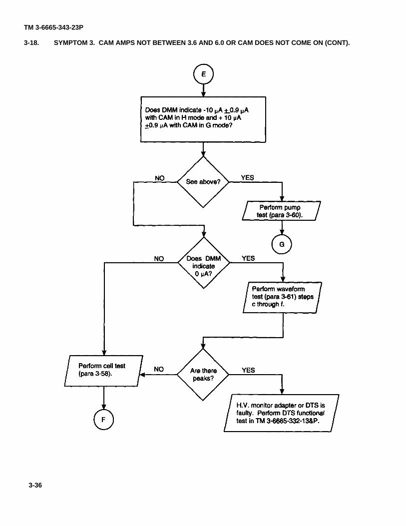
3-18. SYMPTOM 3. CAM AMPS NOT BETWEEN 3.6 AND 6.0 OR CAM DOES NOT COME ON (CONT).
TM 3-6665-332-13&P
para 3-60
para 3-61
para 3-58
3-36
TM 3-6665-343-23P
para 3-49
para 3-59
para 3-31para 3-40
para 3-15
para 3-60
3-37
TM 3-6665-343-23P
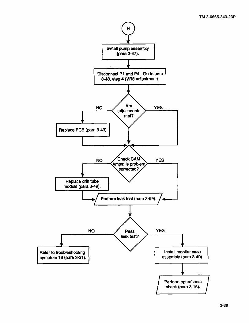
3-18. SYMPTOM 3. CAM AMPS NOT BETWEEN 3.6 AND 6.0 OR CAM DOES NOT COME ON (CONT).
para 3-47
para 3-59
para 3-31 para 3-40
para 3-15
3-38
TM 3-6665-343-23P
para 3-47
para 3-43
para 3-43
para 3-49
para 3-59
para 3-31 para 3-40
para 3-15
3-39
TM 3-6665-343-23P
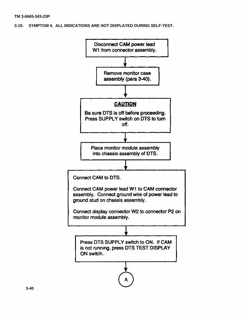
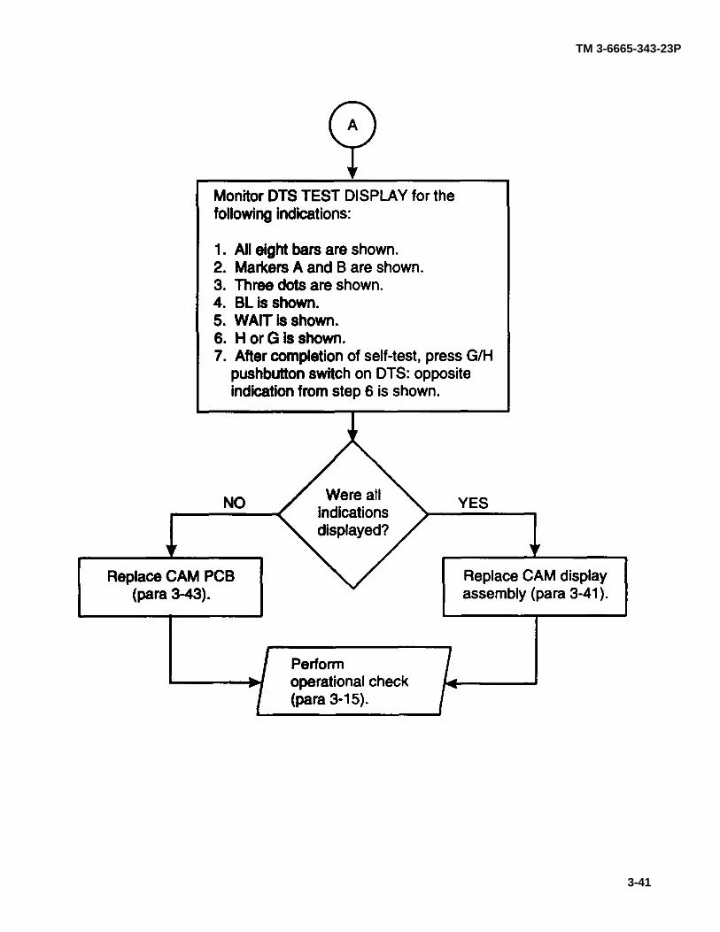
3-19. SYMPTOM 4. ALL INDICATIONS ARE NOT DISPLAYED DURING SELF-TEST.
para 3-40
3-40
TM 3-6665-343-23P
para 3-43
para 3-15
para 3-41
3-41
TM 3-665-343-23P
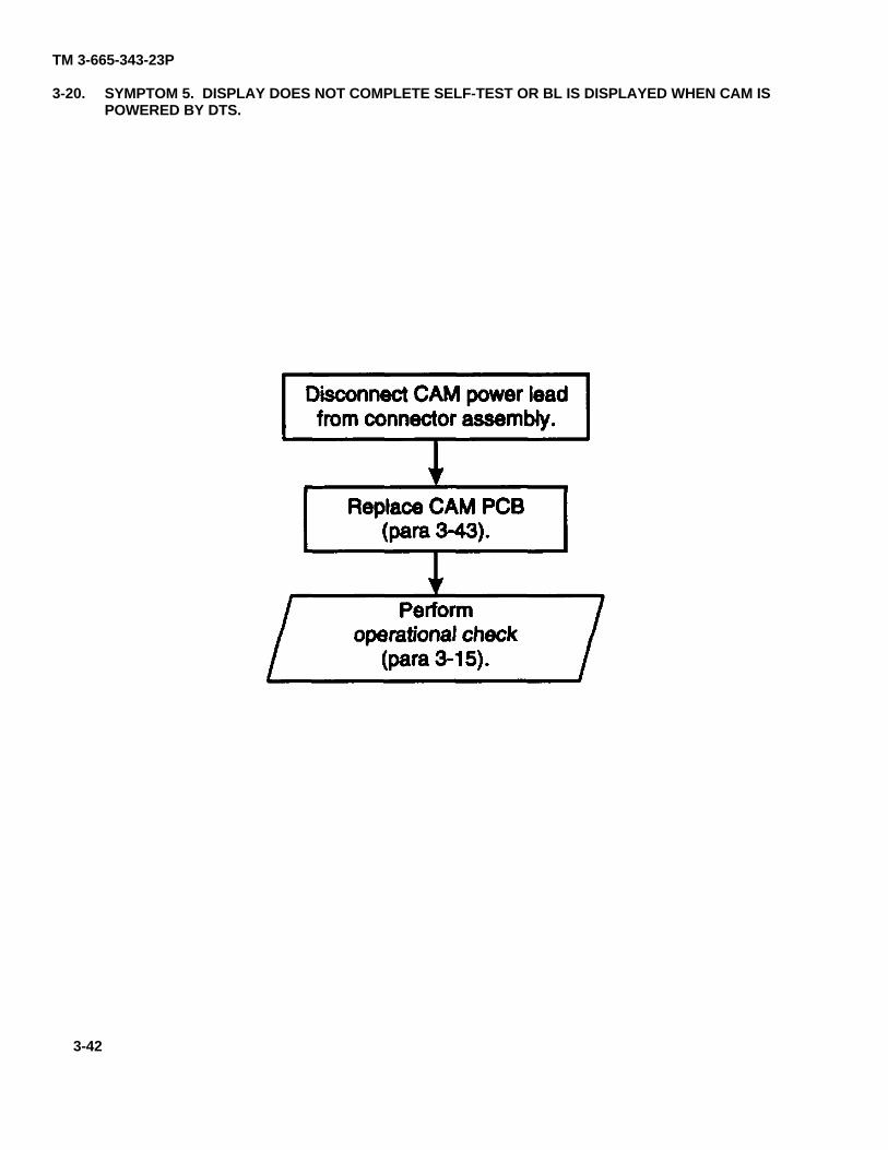
3-20. SYMPTOM 5. DISPLAY DOES NOT COMPLETE SELF-TEST OR BL IS DISPLAYED WHEN CAM ISPOWERED BY DTS.
para 3-43
para 3-15
3-42
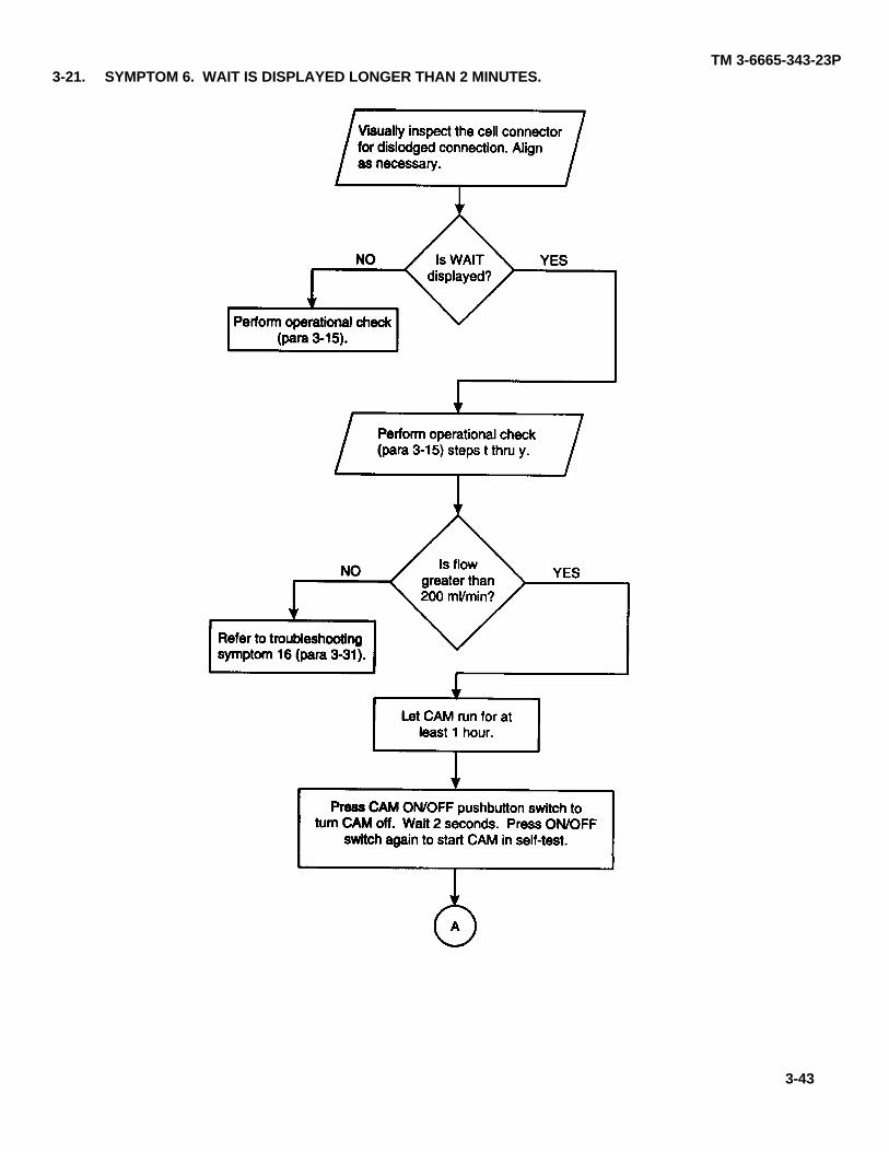
TM 3-6665-343-23P3-21. SYMPTOM 6. WAIT IS DISPLAYED LONGER THAN 2 MINUTES.
para 3-15
para 3-15
para 3-31
3-43
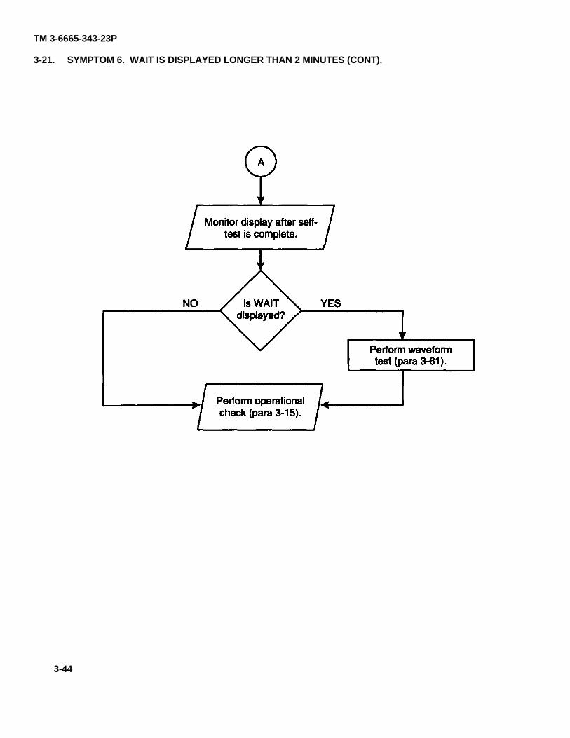
TM 3-6665-343-23P
3-21. SYMPTOM 6. WAIT IS DISPLAYED LONGER THAN 2 MINUTES (CONT).
para 3-61
para 3-15
3-44
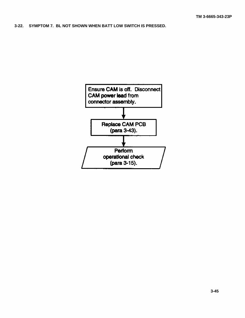
TM 3-6665-343-23P
3-22. SYMPTOM 7. BL NOT SHOWN WHEN BATT LOW SWITCH IS PRESSED.
para 3-15
para 3-43
3-45
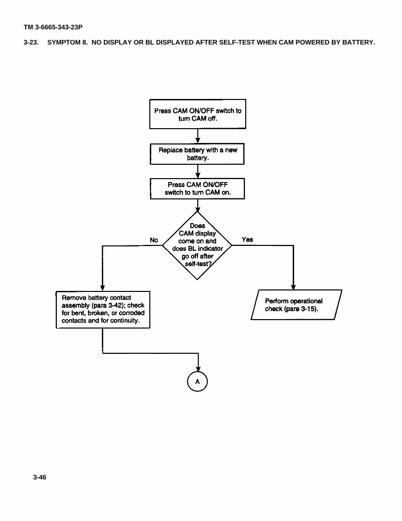
TM 3-6665-343-23P
3-23. SYMPTOM 8. NO DISPLAY OR BL DISPLAYED AFTER SELF-TEST WHEN CAM POWERED BY BATTERY.
para 3-15para 3-42
3-46
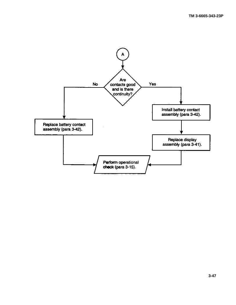
TM 3-6665-343-23P
para 3-42
para 3-42
para 3-15
para 3-41
3-47
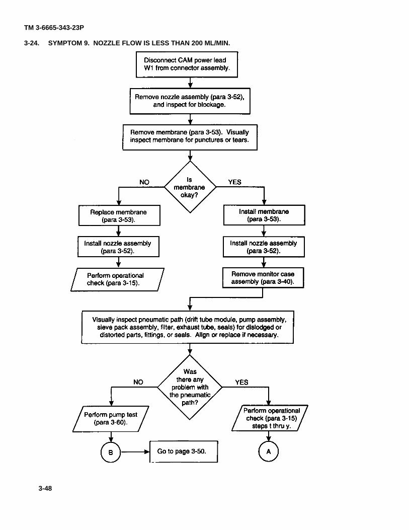
TM 3-6665-343-23P
3-24. SYMPTOM 9. NOZZLE FLOW IS LESS THAN 200 ML/MIN.
para 3-52
para 3-53
para 3-53
para 3-52
para 3-15
para 3-53
para 3-52
para 3-40
para 3-60para 3-15
page 3-50
3-48
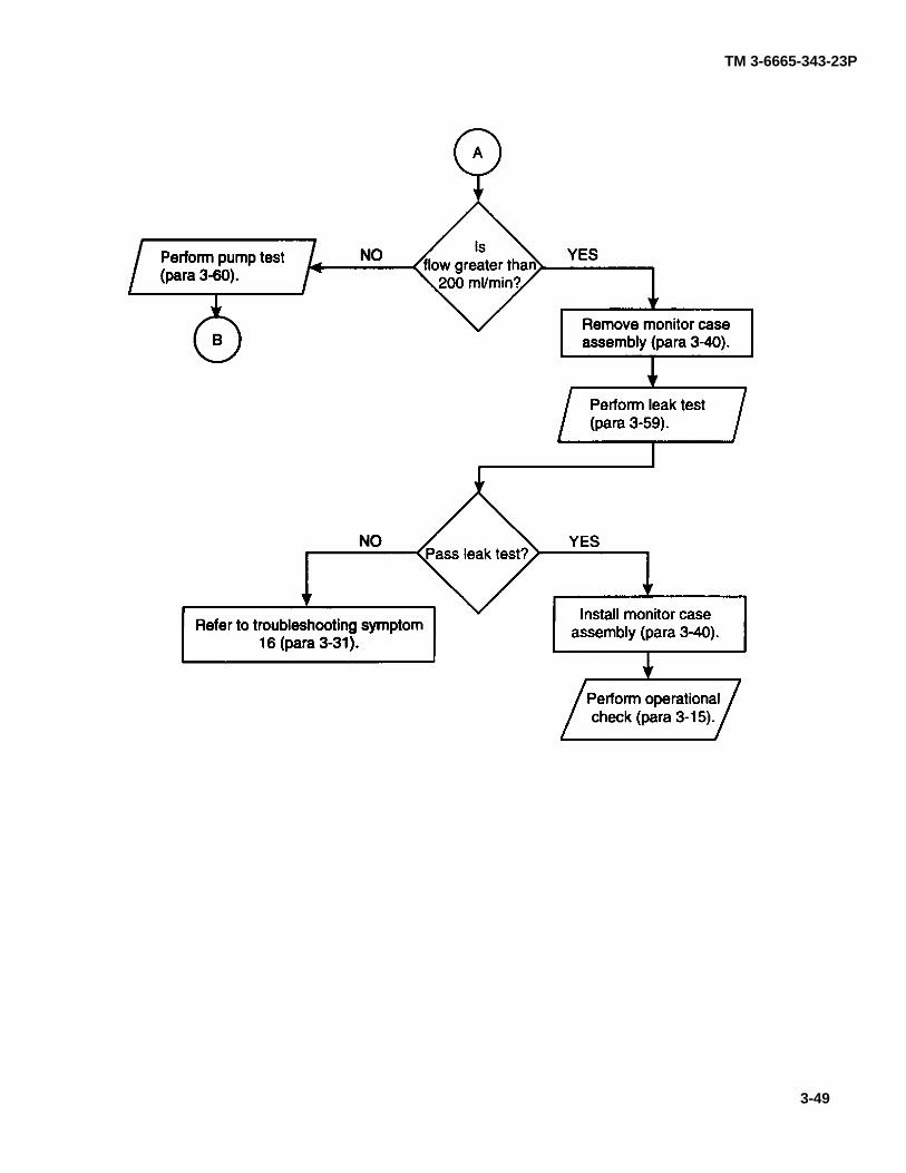
TM 3-6665-343-23P
para 3-60
para 3-40
para 3-59
para 3-31para 3-40
para 3-15
3-49
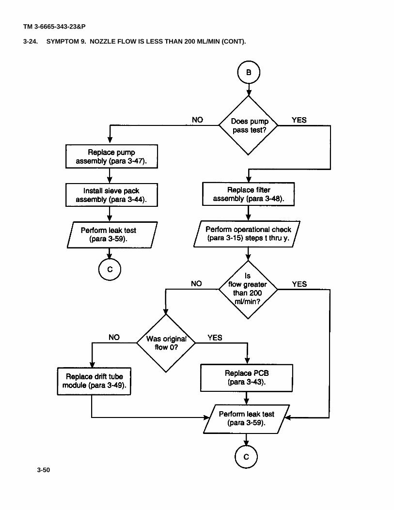
TM 3-6665-343-23&P
3-24. SYMPTOM 9. NOZZLE FLOW IS LESS THAN 200 ML/MIN (CONT).
para 3-47
para 3-44
para 3-59
para 3-48
para 3-15
para 3-49 para 3-43
para 3-59
3-50
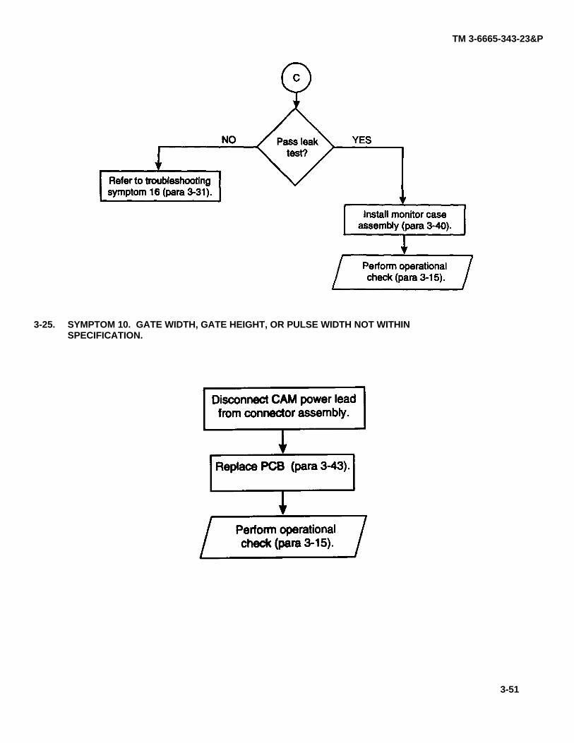
TM 3-6665-343-23&P
3-25. SYMPTOM 10. GATE WIDTH, GATE HEIGHT, OR PULSE WIDTH NOT WITHINSPECIFICATION.
para 3-43
para 3-15
para 3-31
para 3-40
para 3-15
3-51
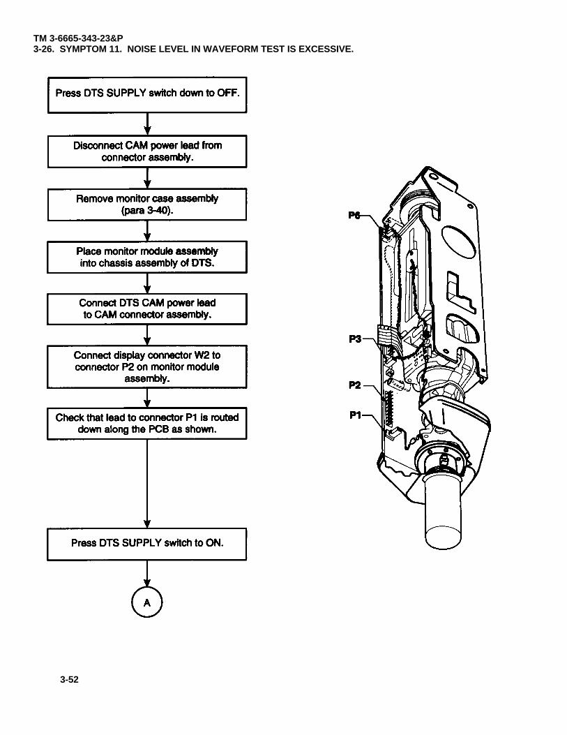
TM 3-6665-343-23&P3-26. SYMPTOM 11. NOISE LEVEL IN WAVEFORM TEST IS EXCESSIVE.
para 3-40
3-52
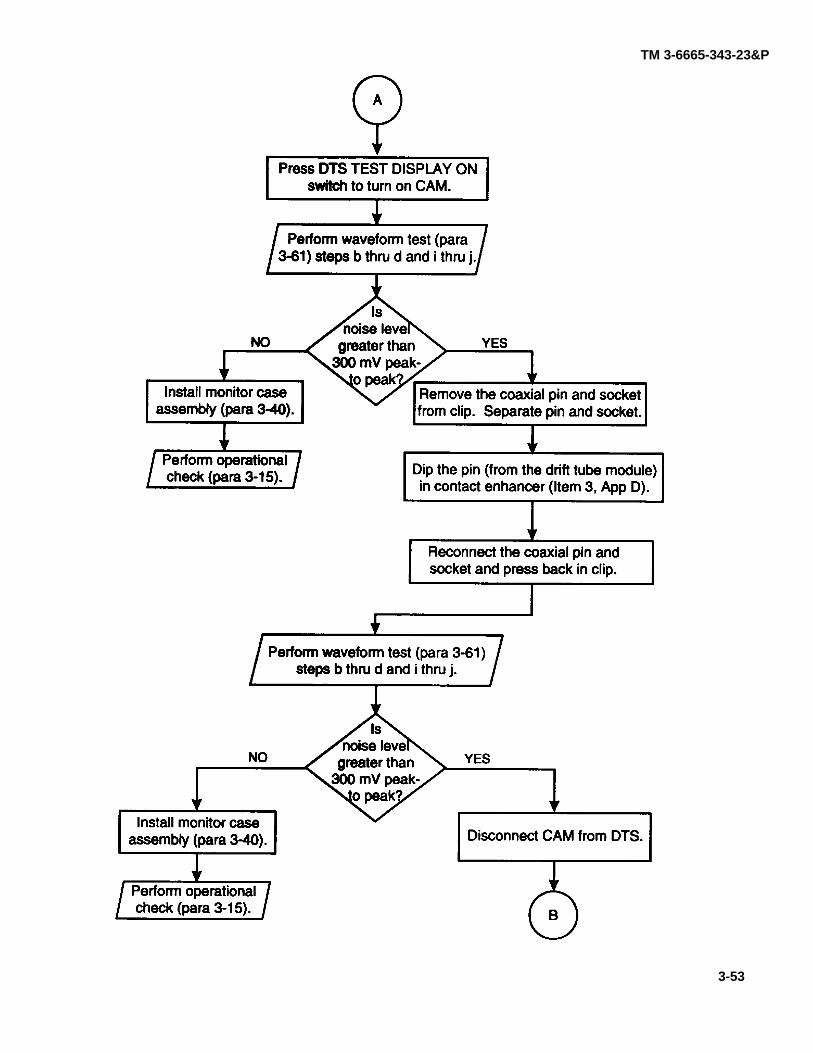
TM 3-6665-343-23&P
para 3-61
para 3-40
para 3-15App D
para 3-61
para 3-40
para 3-15
3-53
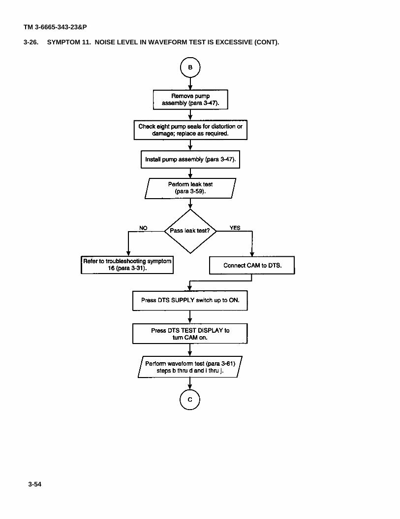
TM 3-6665-343-23&P
3-26. SYMPTOM 11. NOISE LEVEL IN WAVEFORM TEST IS EXCESSIVE (CONT).
para 3-47
para 3-47
para 3-59
para 3-31
para 3-61
3-54
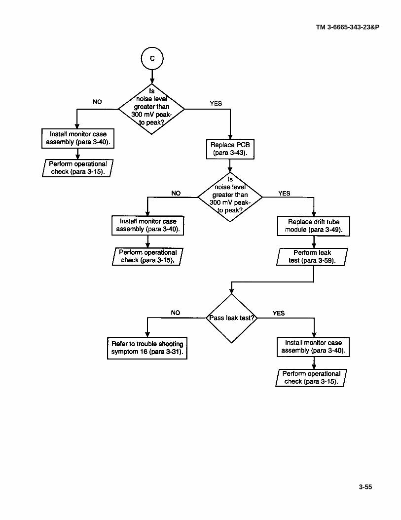
TM 3-6665-343-23&P
para 3-40
para 3-15
para 3-43
para 3-40
para 3-15
para 3-49
para 3-59
para 3-31 para 3-40
para 3-15
3-55
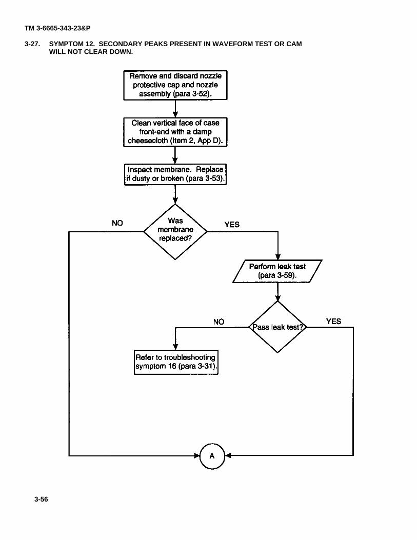
TM 3-6665-343-23&P
3-27. SYMPTOM 12. SECONDARY PEAKS PRESENT IN WAVEFORM TEST OR CAMWILL NOT CLEAR DOWN.
para 3-52
App D
para 3-53
para 3-59
para 3-31
3-56
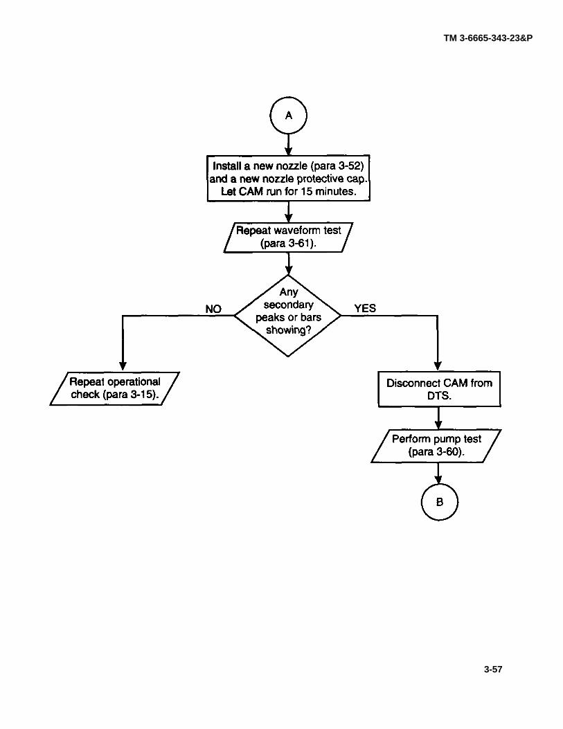
TM 3-6665-343-23&P
para 3-52
para 3-61
para 3-15
para 3-60
3-57
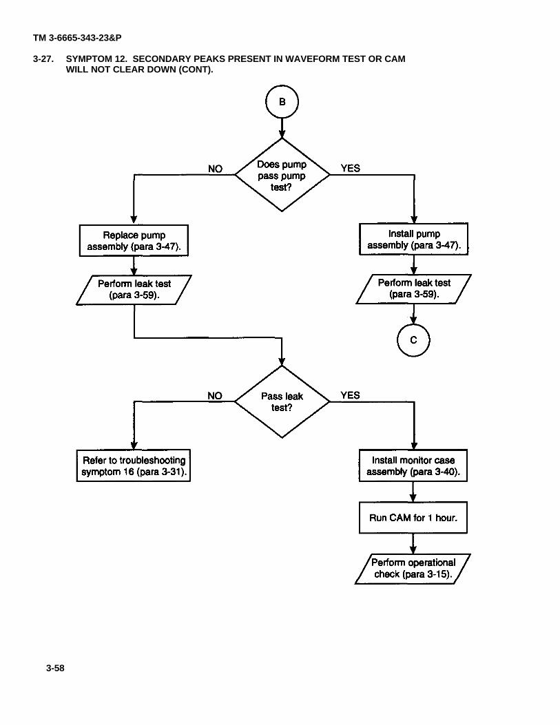
TM 3-6665-343-23&P
3-27. SYMPTOM 12. SECONDARY PEAKS PRESENT IN WAVEFORM TEST OR CAMWILL NOT CLEAR DOWN (CONT).
para 3-47
para 3-59
para 3-47
para 3-59
para 3-31 para 3-40
para 3-15
3-58
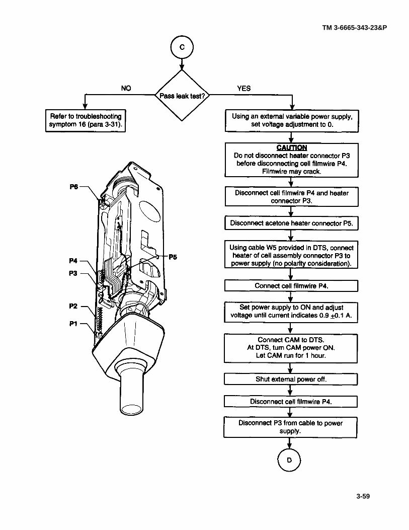
TM 3-6665-343-23&P
para 3-31
3-59
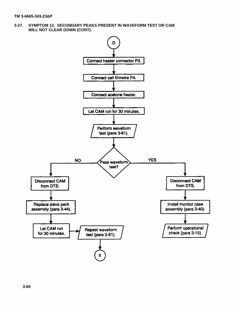
TM 3-6665-343-23&P
3-27. SYMPTOM 12. SECONDARY PEAKS PRESENT IN WAVEFORM TEST OR CAMWILL NOT CLEAR DOWN (CONT).
para 3-61
para 3-44
para 3-61
para 3-40
para 3-15
3-60
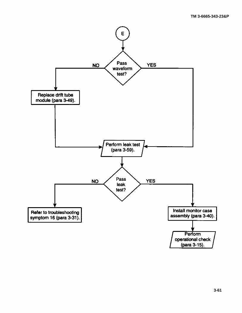
TM 3-6665-343-23&P
para 3-49
para 3-59
para 3-31 para 3-40
para 3-15
3-61
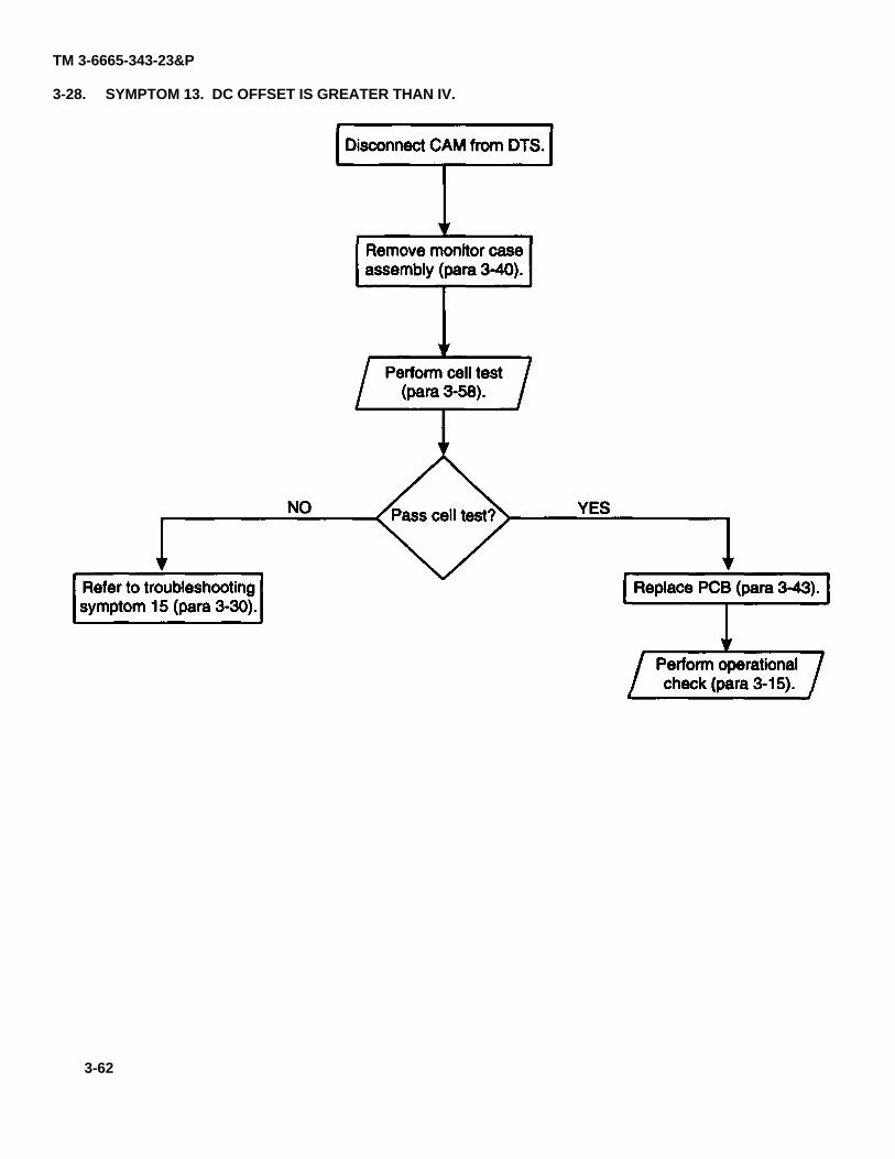
TM 3-6665-343-23&P
3-28. SYMPTOM 13. DC OFFSET IS GREATER THAN IV.
para 3-40
para 3-58
para 3-30para 3-43
para 3-15
3-62
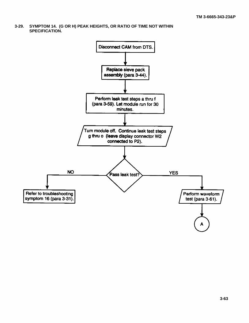
TM 3-6665-343-23&P
3-29. SYMPTOM 14. (G OR H) PEAK HEIGHTS, OR RATIO OF TIME NOT WITHINSPECIFICATION.
para 3-44
para 3-59
para 3-31 para 3-61
3-63
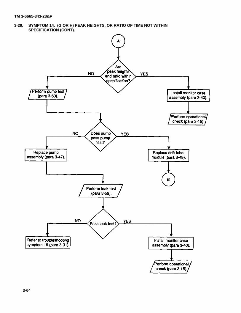
TM 3-6665-343-23&P
3-29. SYMPTOM 14. (G OR H) PEAK HEIGHTS, OR RATIO OF TIME NOT WITHINSPECIFICATION (CONT).
para 3-60 para 3-40
para 3-15
para 3-49para 3-47
para 3-59
para 3-31para 3-40
para 3-15
3-64
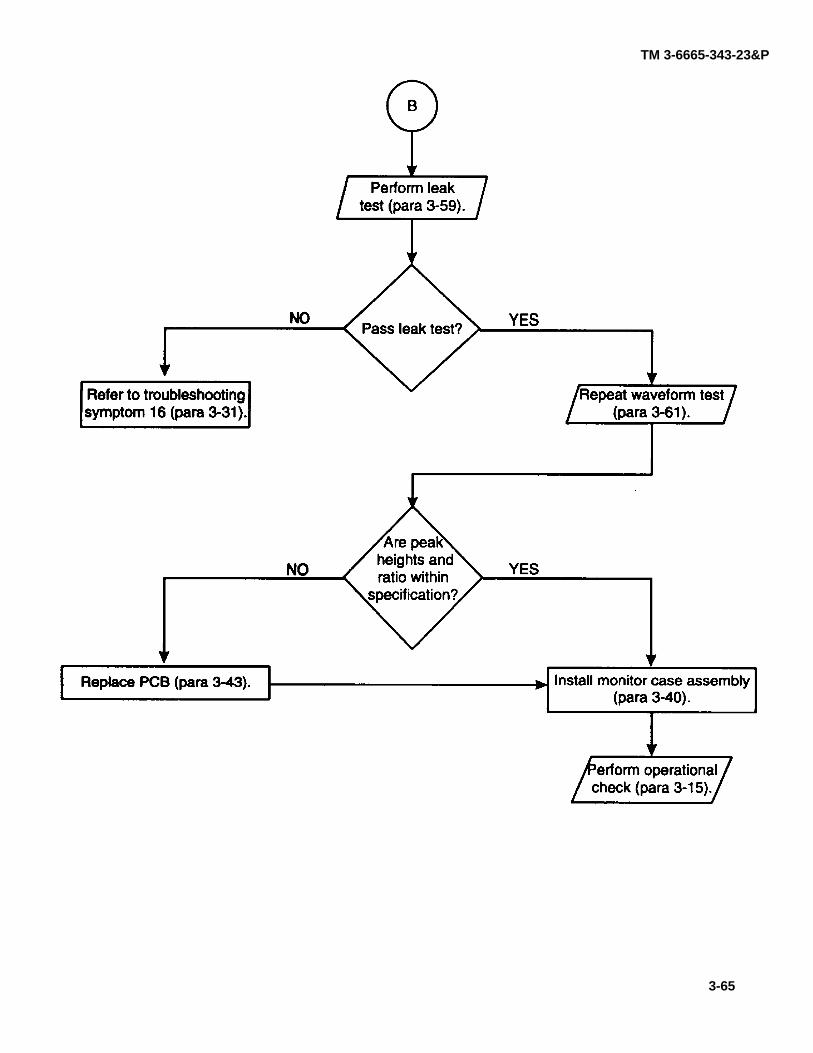
TM 3-6665-343-23&P
para 3-59
para 3-31 para 3-61
para 3-43para 3-40
para 3-15
3-65
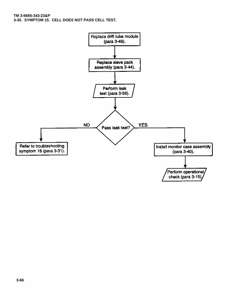
TM 3-6665-343-23&P3-30. SYMPTOM 15. CELL DOES NOT PASS CELL TEST.
para 3-49
para 3-44
para 3-59
para 3-31para 3-40
para 3-15
3-66
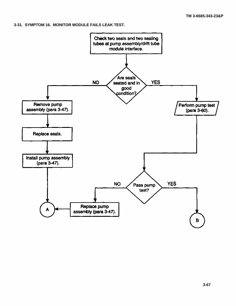
TM 3-6665-343-23&P
3-31. SYMPTOM 16. MONITOR MODULE FAILS LEAK TEST.
para 3-60
para 3-47
para 3-47
para 3-47
3-67
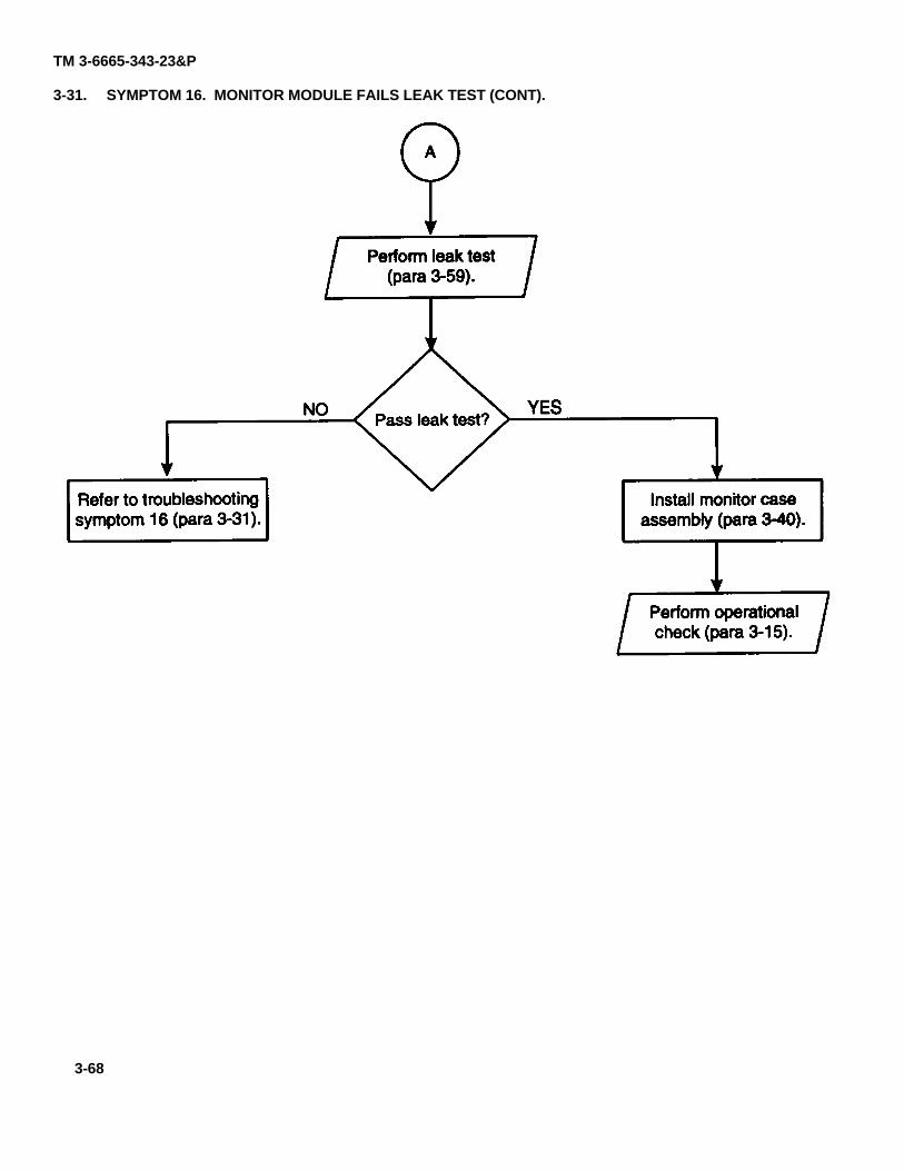
TM 3-6665-343-23&P
3-31. SYMPTOM 16. MONITOR MODULE FAILS LEAK TEST (CONT).
para 3-59
para 3-31para 3-40
para 3-15
3-68
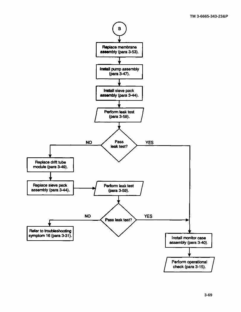
TM 3-6665-343-23&P
para 3-59
para 3-53
para 3-47
para 3-44
para 3-59
para 3-49
para 3-44
para 3-31
para 3-40
para 3-15
3-69
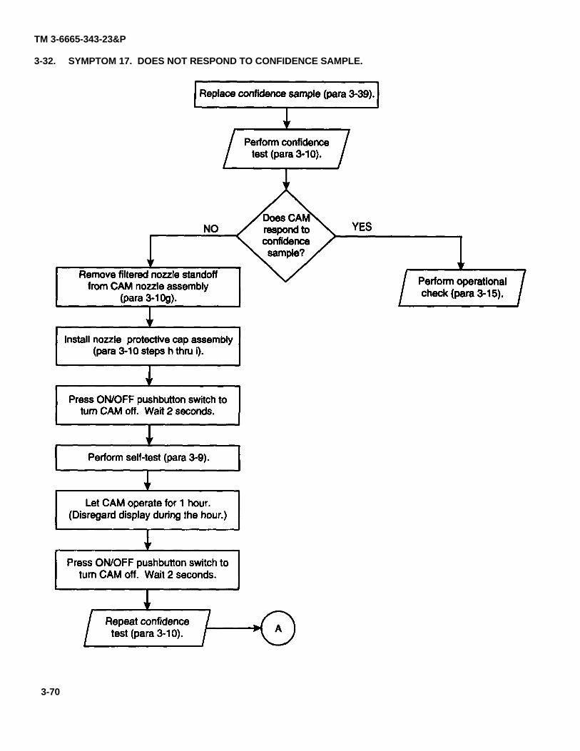
TM 3-6665-343-23&P
3-32. SYMPTOM 17. DOES NOT RESPOND TO CONFIDENCE SAMPLE.
para 3-39
para 3-10
para 3-10
para 3-10
para 3-9
para 3-15
para 3-10
3-70
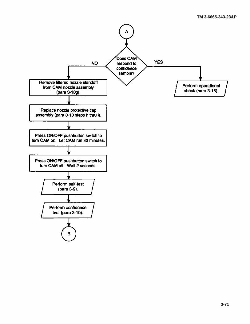
TM 3-6665-343-23&P
para 3-10
para 3-10
para 3-9
para 3-10
para 3-15
3-71
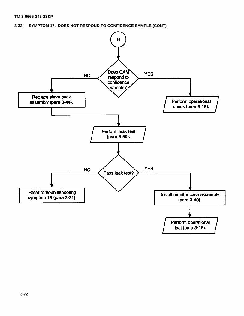
TM 3-6665-343-23&P
3-32. SYMPTOM 17. DOES NOT RESPOND TO CONFIDENCE SAMPLE (CONT).
para 3-44para 3-15
para 3-59
para 3-31 para 3-40
para 3-15
3-72
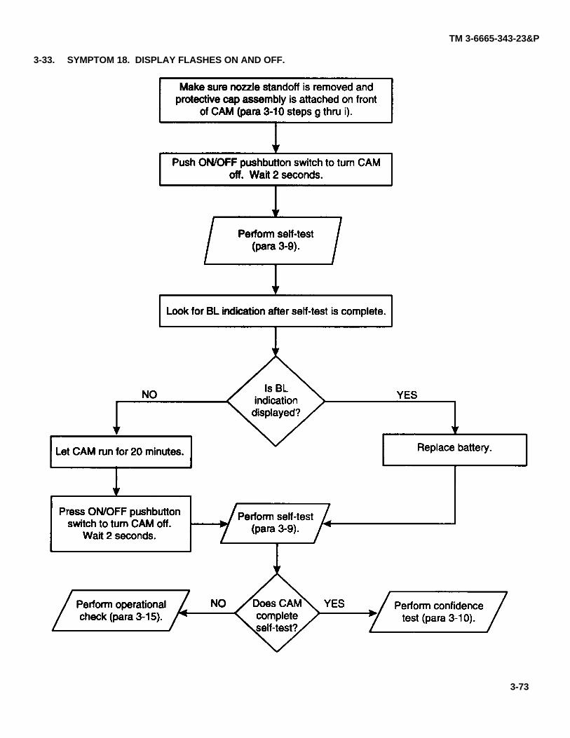
TM 3-6665-343-23&P
3-33. SYMPTOM 18. DISPLAY FLASHES ON AND OFF.
para 3-10
para 3-9
para 3-15
para 3-9
para 3-10
3-73
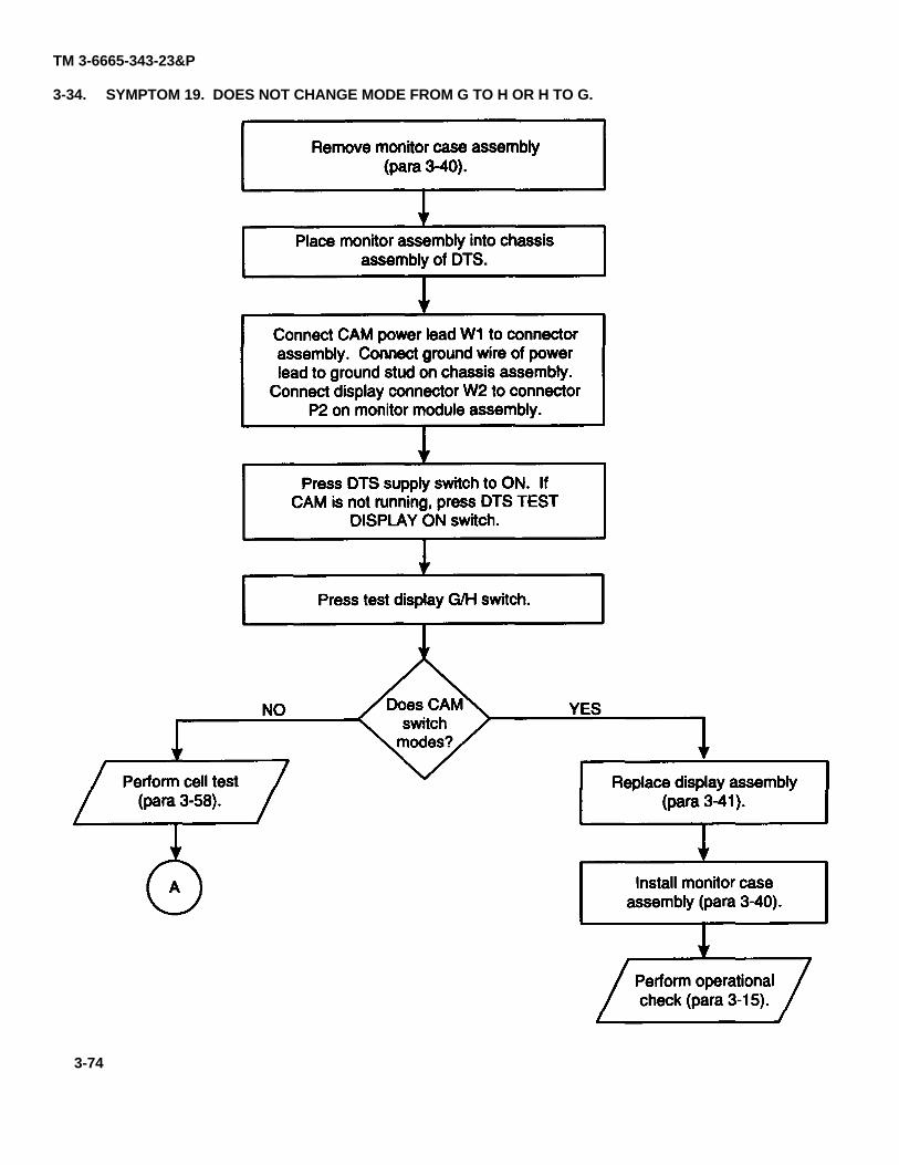
TM 3-6665-343-23&P
3-34. SYMPTOM 19. DOES NOT CHANGE MODE FROM G TO H OR H TO G.
para 3-40
para 3-58 para 3-41
para 3-40
para 3-15
3-74
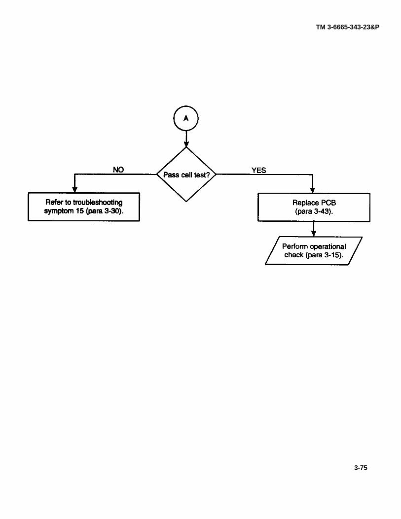
TM 3-6665-343-23&P
para 3-30 para 3-43
para 3-15
3-75
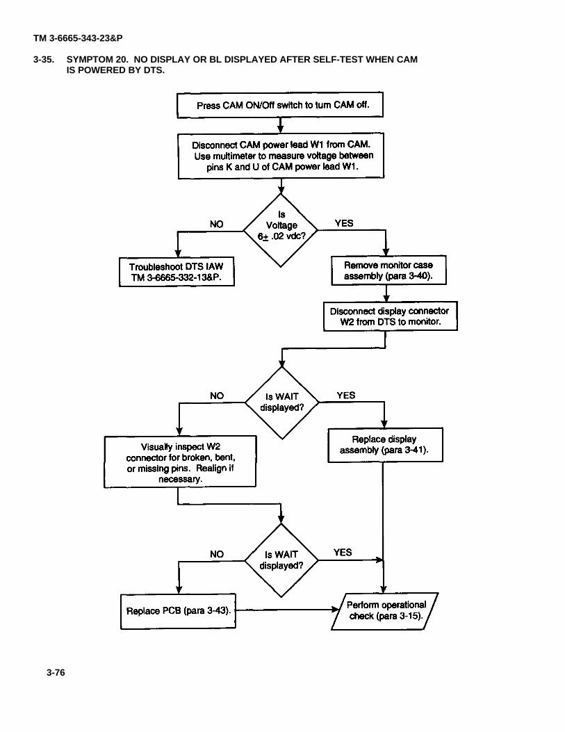
TM 3-6665-343-23&P
3-35. SYMPTOM 20. NO DISPLAY OR BL DISPLAYED AFTER SELF-TEST WHEN CAMIS POWERED BY DTS.
TM 3-6665-332-13&P para 3-40
para 3-41
para 3-15para 3-43
3-76
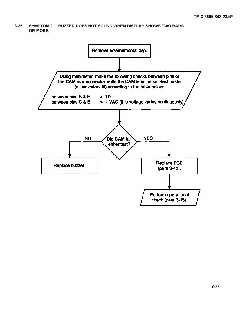
TM 3-6665-343-23&P
3-36. SYMPTOM 21. BUZZER DOES NOT SOUND WHEN DISPLAY SHOWS TWO BARSOR MORE.
para 3-43
para 3-15
3-77
TM 3-6665-343-23&PSection IV. DIRECT SUPPORT MAINTENANCE PROCEDURES
3-37. INTRODUCTION.
WARNING
RADIATION HAZARD
NICKEL-63 (Ni-63)
Wipe test must be performed before and after any maintenance or testing of CAM.
This section consists of general maintenance instructions, detailed Direct Support maintenance procedures, andperformance tests. Read and understand the general instructions before beginning the detailed procedures. Use thefollowing index to locate Direct Support maintenance procedures and performance tests.
Performance Tests
CELL TEST.........................................................................................................................................LEAK TEST ........................................................................................................................................PUMP TEST .......................................................................................................................................WAVEFORM TEST.............................................................................................................................
Assembly/Part - Maintenance Procedures
CONFIDENCE SAMPLE REPLACEMENT ..........................................................................................MONITOR CASE ASSEMBLY REPLACEMENT..................................................................................DISPLAY ASSEMBLY REPLACEMENT..............................................................................................BATTERY CONTACT ASSEMBLY REPLACEMENT...........................................................................PRINTED CIRCUIT BOARD REPLACEMENT AND ADJUSTMENT....................................................SIEVE PACK ASSEMBLY REPLACEMENT........................................................................................CONNECTOR ASSEMBLY REPLACEMENT ......................................................................................PRINTED WIRING BOARD REPLACEMENT......................................................................................PUMP ASSEMBLY REPLACEMENT ..................................................................................................FILTER ASSEMBLY REPLACEMENT.................................................................................................DRIFT TUBE MODULE REPLACEMENT AND ALIGNMENT ..............................................................NOZZLE HOLDER ASSEMBLY REPLACEMENT ...............................................................................CASE FRONT-END REPLACEMENT .................................................................................................NOZZLE ASSEMBLY REPLACEMENT...............................................................................................MEMBRANE ASSEMBLY REPLACEMENT ........................................................................................ENVIRONMENTAL CAP ASSEMBLY REPLACEMENT.......................................................................BATTERY CAP ASSEMBLY REPLACEMENT ....................................................................................CARRYING CASE ASSEMBLY REPLACEMENT................................................................................CARRYING CASE STRAP REPLACEMENT.......................................................................................
3-78
Para
3-583-593-603-61
Para
3-393-403-413-423-433-443-453-463-473-483-493-503-513-523-533-543-553-563-57
TM 3-6665-343-23&P
3-38. GENERAL MAINTENANCE INSTRUCTIONS.
The following general maintenance procedures are to be followed whenever performing maintenance on a CAM.
a. Inspect CAM, including case and display window for any cracked or broken parts. Replace any cracked orbroken parts.
b. Inspect all removed assemblies/parts for tears, breaks, indications of wear, and corrosion. Replace any partsshowing these faults.
c. Observe all parts for cleanliness. If parts appear to have dust on them, blow the dust off.
d. Check the threads of all removed screws for the presence of Tuflok. If Tuflok no longer remains in thethreads, replace the screw(s).
e. Prior to working on a CAM, prepare a clean work surface. Follow work preparation instructions per Chapter 3,Section I.
f. DO NOT remove a new CAM assembly/part from its packaging until you are ready to install it. This will keepthe assembly/part clean and dry.
g. Open the pneumatic loop of a CAM (opening the sieve pack, pump assembly, drift tube module, membrane,nozzle assembly) only long enough to make required tests and/or replacements.
3-79/(3-80 blank)
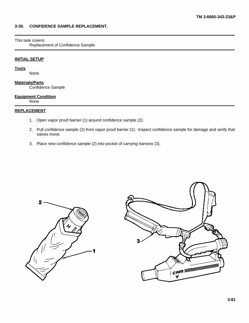
TM 3-6665-343-23&P
3-39. CONFIDENCE SAMPLE REPLACEMENT.
This task covers:Replacement of Confidence Sample.
INITIAL SETUP
ToolsNone
Materials/PartsConfidence Sample
Equipment ConditionNone
REPLACEMENT
1. Open vapor proof barrier (1) around confidence sample (2).
2. Pull confidence sample (2) from vapor proof barrier (1). Inspect confidence sample for damage and verify thatvalves move.
3. Place new confidence sample (2) into pocket of carrying harness (3).
3-81
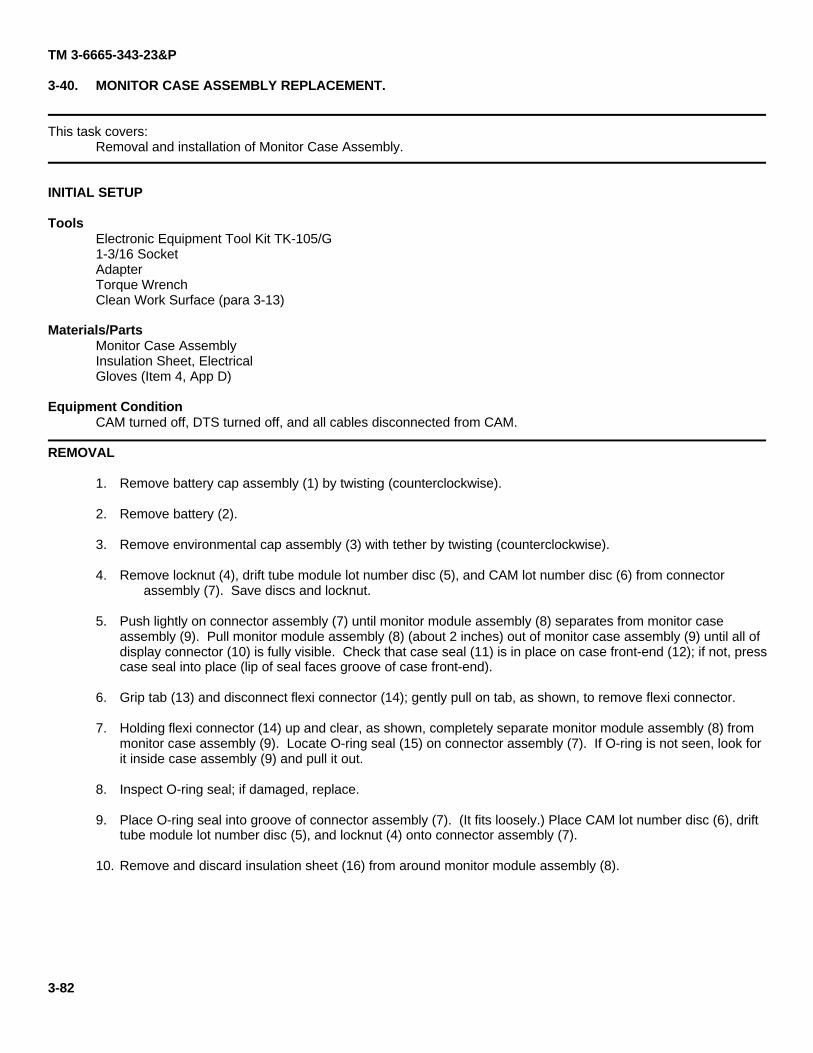
TM 3-6665-343-23&P
3-40. MONITOR CASE ASSEMBLY REPLACEMENT.
This task covers:Removal and installation of Monitor Case Assembly.
INITIAL SETUP
ToolsElectronic Equipment Tool Kit TK-105/G1-3/16 SocketAdapterTorque WrenchClean Work Surface (para 3-13)
Materials/PartsMonitor Case AssemblyInsulation Sheet, ElectricalGloves (Item 4, App D)
Equipment ConditionCAM turned off, DTS turned off, and all cables disconnected from CAM.
REMOVAL
1. Remove battery cap assembly (1) by twisting (counterclockwise).
2. Remove battery (2).
3. Remove environmental cap assembly (3) with tether by twisting (counterclockwise).
4. Remove locknut (4), drift tube module lot number disc (5), and CAM lot number disc (6) from connectorassembly (7). Save discs and locknut.
5. Push lightly on connector assembly (7) until monitor module assembly (8) separates from monitor caseassembly (9). Pull monitor module assembly (8) (about 2 inches) out of monitor case assembly (9) until all ofdisplay connector (10) is fully visible. Check that case seal (11) is in place on case front-end (12); if not, presscase seal into place (lip of seal faces groove of case front-end).
6. Grip tab (13) and disconnect flexi connector (14); gently pull on tab, as shown, to remove flexi connector.
7. Holding flexi connector (14) up and clear, as shown, completely separate monitor module assembly (8) frommonitor case assembly (9). Locate O-ring seal (15) on connector assembly (7). If O-ring is not seen, look forit inside case assembly (9) and pull it out.
8. Inspect O-ring seal; if damaged, replace.
9. Place O-ring seal into groove of connector assembly (7). (It fits loosely.) Place CAM lot number disc (6), drifttube module lot number disc (5), and locknut (4) onto connector assembly (7).
10. Remove and discard insulation sheet (16) from around monitor module assembly (8).
3-82
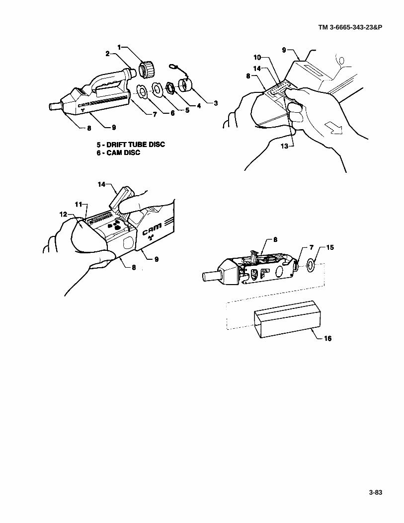
TM 3-6665-343-23&P
3-83
TM 3-6665-343-23&P
3-40. MONITOR CASE ASSEMBLY REPLACEMENT (CONT).
INSTALLATION
1. Install new insulation sheet (16) around monitor module assembly (8) and hold it in place: position as shown.
NOTE
In steps 2 through 5, keep monitor module assembly tilted with the rear connectorfacing upward so that the O-ring seal (15) remains in place.
2. Remove locknut (4), drift tube module lot number disc (5), and CAM lot number disc (6) from connectorassembly (7).
3. Fold flexi connector (14) out of the way above the front access area of the monitor case assembly (9) and holdthe flexi connector in place.
4. Partially (until the display connector (10) is still just accessible) slide monitor module assembly (8) withinsulation sheet (16) into monitor case assembly (9).
5. Using tab (13) to hold flexi connector (14), gently press flexi connector (14) to mate with display connector(10) until flush with PCB. Look under tab (13) at connector to be sure sockets have not been pushed out ofconnector; if they are out, press sockets gently into connector with small flat-tip screwdriver. Slide monitormodule assembly (8) completely into monitor case assembly (9).
6. Hold CAM vertically and look through hole in end at the connector assembly (7) to see if O-ring seal (15) is inthe groove around connector assembly (7).
7. Install CAM lot number disc (6), drift tube module lot number disc (5), and locknut (4) onto connector assembly(7).
NOTE
Insure discs are not engaged in connector threads. When properly assembled,one to two threads will extend through the locknut.
8. Check that the gap between the case front-end (12) and the monitor case assembly (9) has closed and thatthe case seal (11) is not pinched. Tighten locknut (4) until tight; torque to 87 in. lb.
9. Install environmental cap assembly with tether (3) by twisting (clockwise).
10. Install battery (2) (terminal end goes in first).
11. Install battery cap assembly (1) by twisting (clockwise).
3-84
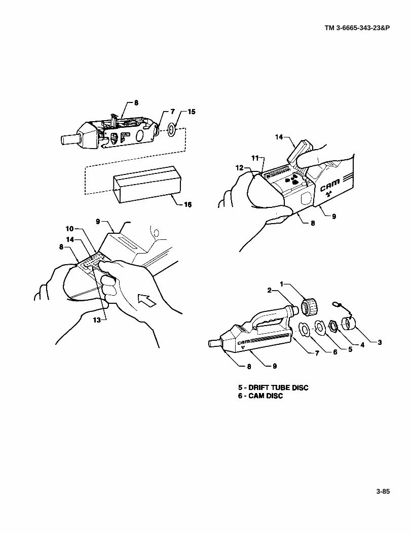
TM 3-6665-343-23&P
3-85
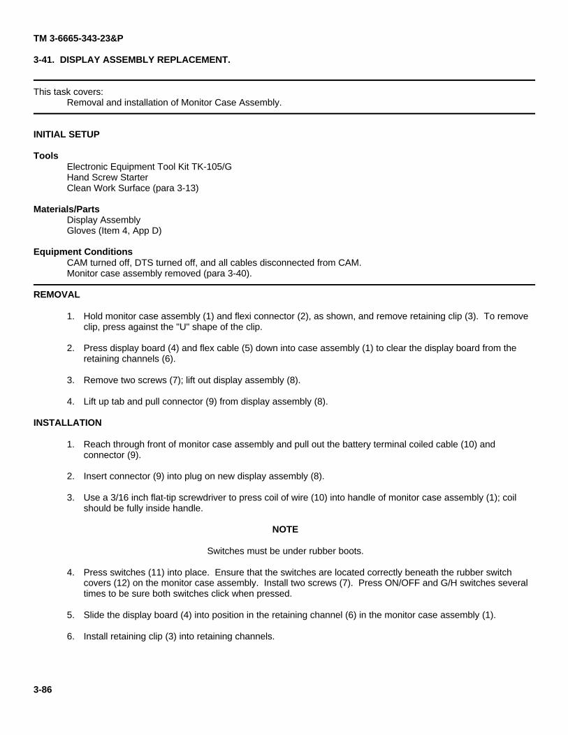
TM 3-6665-343-23&P
3-41. DISPLAY ASSEMBLY REPLACEMENT.
This task covers:Removal and installation of Monitor Case Assembly.
INITIAL SETUP
ToolsElectronic Equipment Tool Kit TK-105/GHand Screw StarterClean Work Surface (para 3-13)
Materials/PartsDisplay AssemblyGloves (Item 4, App D)
Equipment ConditionsCAM turned off, DTS turned off, and all cables disconnected from CAM.Monitor case assembly removed (para 3-40).
REMOVAL
1. Hold monitor case assembly (1) and flexi connector (2), as shown, and remove retaining clip (3). To removeclip, press against the "U" shape of the clip.
2. Press display board (4) and flex cable (5) down into case assembly (1) to clear the display board from theretaining channels (6).
3. Remove two screws (7); lift out display assembly (8).
4. Lift up tab and pull connector (9) from display assembly (8).
INSTALLATION
1. Reach through front of monitor case assembly and pull out the battery terminal coiled cable (10) andconnector (9).
2. Insert connector (9) into plug on new display assembly (8).
3. Use a 3/16 inch flat-tip screwdriver to press coil of wire (10) into handle of monitor case assembly (1); coilshould be fully inside handle.
NOTE
Switches must be under rubber boots.
4. Press switches (11) into place. Ensure that the switches are located correctly beneath the rubber switchcovers (12) on the monitor case assembly. Install two screws (7). Press ON/OFF and G/H switches severaltimes to be sure both switches click when pressed.
5. Slide the display board (4) into position in the retaining channel (6) in the monitor case assembly (1).
6. Install retaining clip (3) into retaining channels.
3-86
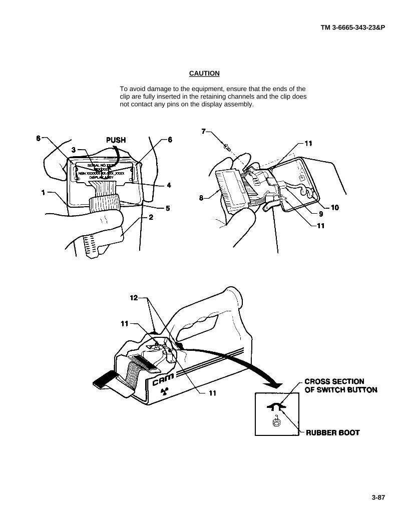
TM 3-6665-343-23&P
CAUTION
To avoid damage to the equipment, ensure that the ends of theclip are fully inserted in the retaining channels and the clip doesnot contact any pins on the display assembly.
3-87
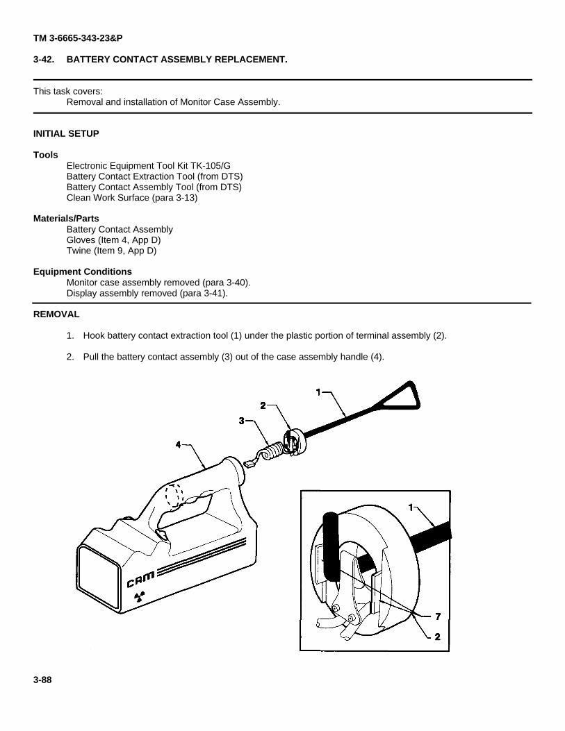
TM 3-6665-343-23&P
3-42. BATTERY CONTACT ASSEMBLY REPLACEMENT.
This task covers:Removal and installation of Monitor Case Assembly.
INITIAL SETUP
ToolsElectronic Equipment Tool Kit TK-105/GBattery Contact Extraction Tool (from DTS)Battery Contact Assembly Tool (from DTS)Clean Work Surface (para 3-13)
Materials/PartsBattery Contact AssemblyGloves (Item 4, App D)Twine (Item 9, App D)
Equipment ConditionsMonitor case assembly removed (para 3-40).Display assembly removed (para 3-41).
REMOVAL
1. Hook battery contact extraction tool (1) under the plastic portion of terminal assembly (2).
2. Pull the battery contact assembly (3) out of the case assembly handle (4).
3-88
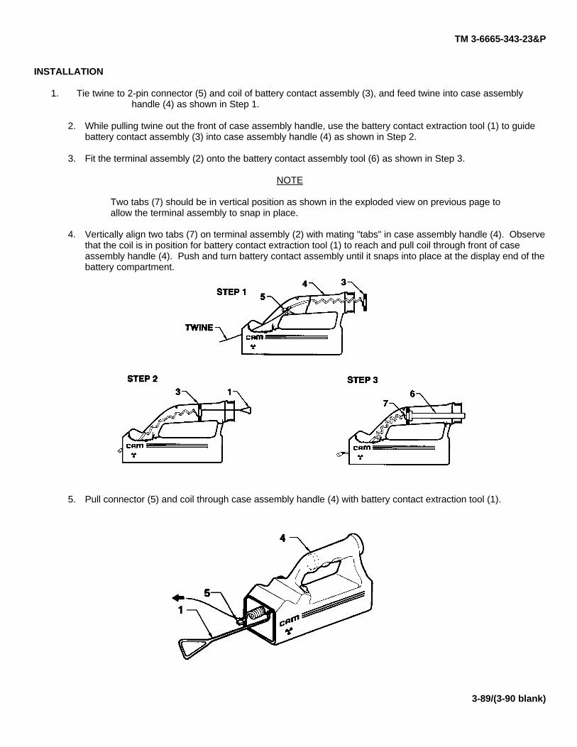
TM 3-6665-343-23&P
INSTALLATION
1. Tie twine to 2-pin connector (5) and coil of battery contact assembly (3), and feed twine into case assemblyhandle (4) as shown in Step 1.
2. While pulling twine out the front of case assembly handle, use the battery contact extraction tool (1) to guidebattery contact assembly (3) into case assembly handle (4) as shown in Step 2.
3. Fit the terminal assembly (2) onto the battery contact assembly tool (6) as shown in Step 3.
NOTE
Two tabs (7) should be in vertical position as shown in the exploded view on previous page toallow the terminal assembly to snap in place.
4. Vertically align two tabs (7) on terminal assembly (2) with mating "tabs" in case assembly handle (4). Observethat the coil is in position for battery contact extraction tool (1) to reach and pull coil through front of caseassembly handle (4). Push and turn battery contact assembly until it snaps into place at the display end of thebattery compartment.
5. Pull connector (5) and coil through case assembly handle (4) with battery contact extraction tool (1).
3-89/(3-90 blank)
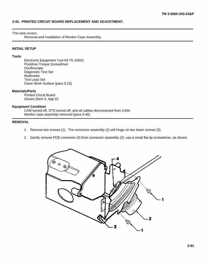
TM 3-6665-343-23&P
3-43. PRINTED CIRCUIT BOARD REPLACEMENT AND ADJUSTMENT.
This task covers:Removal and installation of Monitor Case Assembly.
INITIAL SETUP
ToolsElectronic Equipment Tool Kit TK-105/GPosidrive Torque ScrewdriverOscilloscopeDiagnostic Test SetMultimeterTest Lead SetClean Work Surface (para 3-13)
Materials/PartsPrinted Circuit BoardGloves (Item 4, App D)
Equipment ConditionCAM turned off, DTS turned off, and all cables disconnected from CAM.Monitor case assembly removed (para 3-40).
REMOVAL
1. Remove two screws (1). The connector assembly (2) will hinge on two lower screws (3).
2. Gently remove PCB connector (4) from connector assembly (2); use a small flat-tip screwdriver, as shown.
3-91
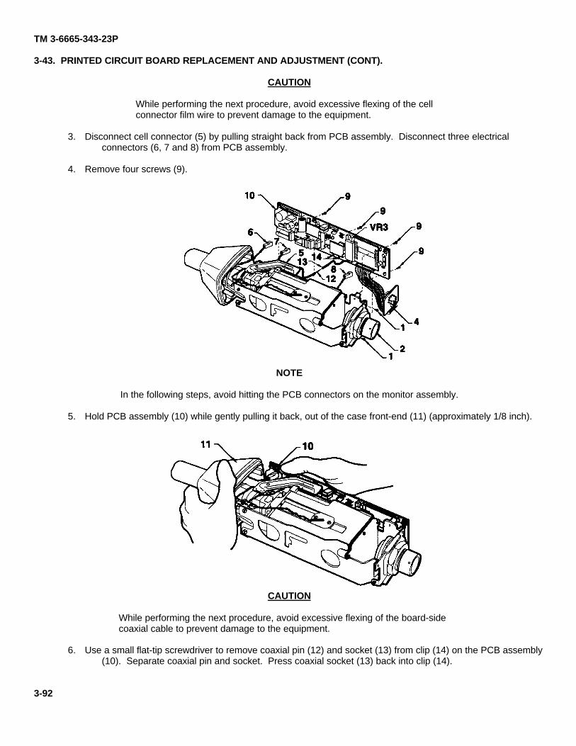
TM 3-6665-343-23P
3-43. PRINTED CIRCUIT BOARD REPLACEMENT AND ADJUSTMENT (CONT).
CAUTION
While performing the next procedure, avoid excessive flexing of the cellconnector film wire to prevent damage to the equipment.
3. Disconnect cell connector (5) by pulling straight back from PCB assembly. Disconnect three electricalconnectors (6, 7 and 8) from PCB assembly.
4. Remove four screws (9).
NOTE
In the following steps, avoid hitting the PCB connectors on the monitor assembly.
5. Hold PCB assembly (10) while gently pulling it back, out of the case front-end (11) (approximately 1/8 inch).
CAUTION
While performing the next procedure, avoid excessive flexing of the board-sidecoaxial cable to prevent damage to the equipment.
6. Use a small flat-tip screwdriver to remove coaxial pin (12) and socket (13) from clip (14) on the PCB assembly(10). Separate coaxial pin and socket. Press coaxial socket (13) back into clip (14).
3-92
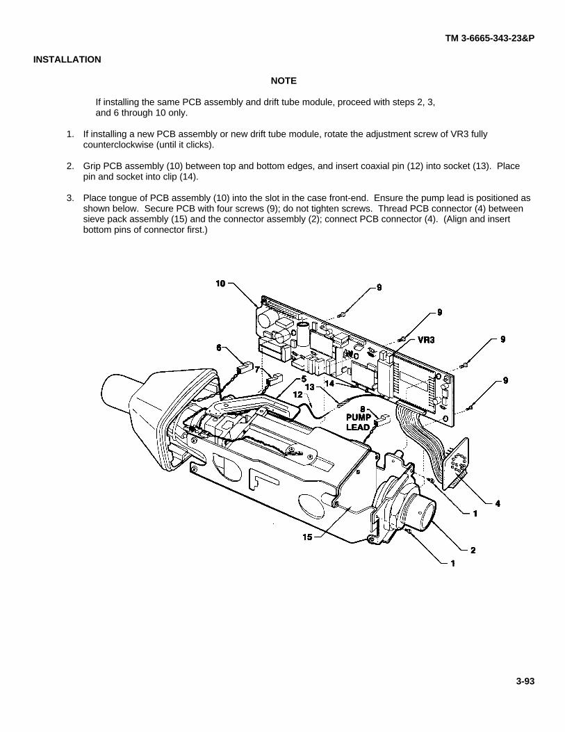
TM 3-6665-343-23&P
INSTALLATION
NOTE
If installing the same PCB assembly and drift tube module, proceed with steps 2, 3,and 6 through 10 only.
1. If installing a new PCB assembly or new drift tube module, rotate the adjustment screw of VR3 fullycounterclockwise (until it clicks).
2. Grip PCB assembly (10) between top and bottom edges, and insert coaxial pin (12) into socket (13). Placepin and socket into clip (14).
3. Place tongue of PCB assembly (10) into the slot in the case front-end. Ensure the pump lead is positioned asshown below. Secure PCB with four screws (9); do not tighten screws. Thread PCB connector (4) betweensieve pack assembly (15) and the connector assembly (2); connect PCB connector (4). (Align and insertbottom pins of connector first.)
3-93
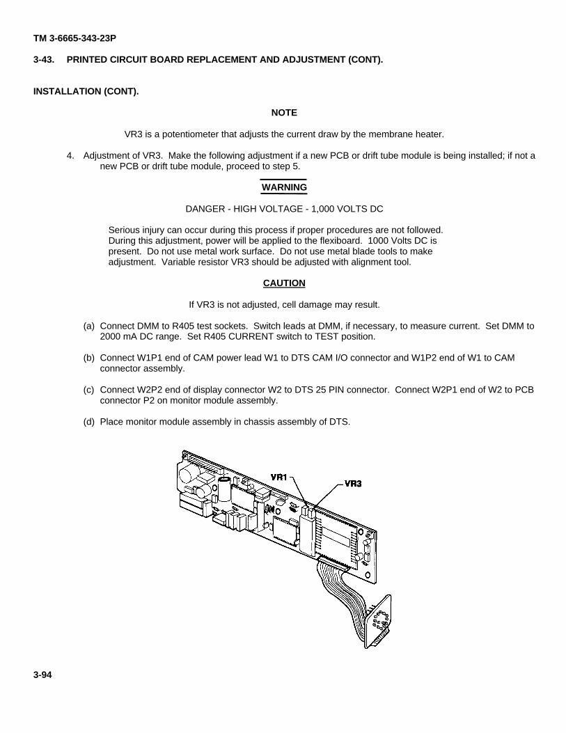
TM 3-6665-343-23P
3-43. PRINTED CIRCUIT BOARD REPLACEMENT AND ADJUSTMENT (CONT).
INSTALLATION (CONT).
NOTE
VR3 is a potentiometer that adjusts the current draw by the membrane heater.
4. Adjustment of VR3. Make the following adjustment if a new PCB or drift tube module is being installed; if not anew PCB or drift tube module, proceed to step 5.
WARNING
DANGER - HIGH VOLTAGE - 1,000 VOLTS DC
Serious injury can occur during this process if proper procedures are not followed.During this adjustment, power will be applied to the flexiboard. 1000 Volts DC ispresent. Do not use metal work surface. Do not use metal blade tools to makeadjustment. Variable resistor VR3 should be adjusted with alignment tool.
CAUTION
If VR3 is not adjusted, cell damage may result.
(a) Connect DMM to R405 test sockets. Switch leads at DMM, if necessary, to measure current. Set DMM to2000 mA DC range. Set R405 CURRENT switch to TEST position.
(b) Connect W1P1 end of CAM power lead W1 to DTS CAM I/O connector and W1P2 end of W1 to CAMconnector assembly.
(c) Connect W2P2 end of display connector W2 to DTS 25 PIN connector. Connect W2P1 end of W2 to PCBconnector P2 on monitor module assembly.
(d) Place monitor module assembly in chassis assembly of DTS.
3-94
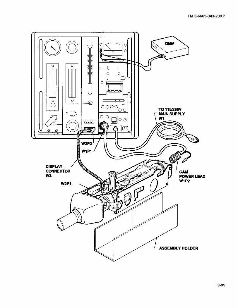
TM 3-6665-343-23&P
3-95
TM 3-6665-343-23P
3-43. PRINTED CIRCUIT BOARD REPLACEMENT AND ADJUSTMENT (CONT).
INSTALLATION (CONT).
(e) Connect pump motor connector (8) to P6.
(f) Press DTS SUPPLY switch up to ON. Press TEST DISPLAY ON switch to turn monitor module assemblyon.
(g) Wait 60 seconds and measure and record the "baseline current" in milliamperes shown on the DMM.
(h) Press TEST DISPLAY ON switch to turn monitor module assembly off.
CAUTION
When adjusting VR3 in the next step, ensure that the adjustment is made slowlyso that the calculated current is NOT exceeded. If the current is excessive, themembrane heater may be destroyed.
(i) Connect cell filmwire connector (5) to P4. Press TEST DISPLAY ON switch to turn monitor moduleassembly on. Adjust VR3 until DMM indicates baseline current recorded in step 4(g) plus 76 ±5 mA.
(j) Press TEST DISPLAY ON switch to turn monitor module assembly off.
(k) Connect nozzle heater connector (6) to P1. To the baseline current recorded in step 4(g) add 186 mA.
(I) Press TEST DISPLAY ON switch to turn monitor module assembly on. Wait 2 minutes. Verify thatcurrent indicates the value of step 4(k) ± 40 mA. If not, repeat adjustment starting at step (e).
(m) Press TEST DISPLAY ON switch to turn monitor module assembly off. Disconnect cell filmwire (5).Connect heaters/PCB connector (7) to P3. Connect cell filmwire (5).
(n) Disconnect display connector (16) from P2. Disconnect CAM power lead W1 from connector assembly(2).
5. Disconnect the DMM from the DTS and set R405 CURRENT switch to NORM.
3-96
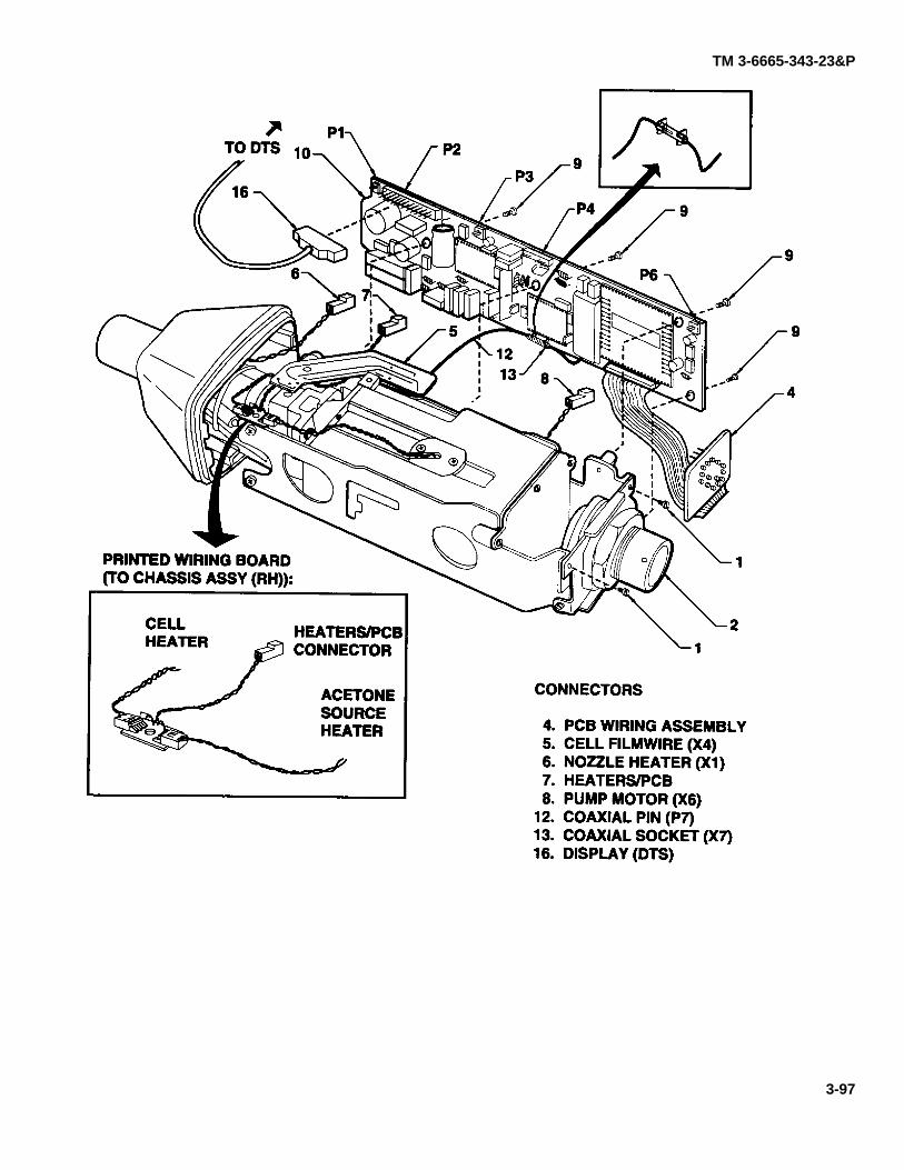
TM 3-6665-343-23&P
3-97
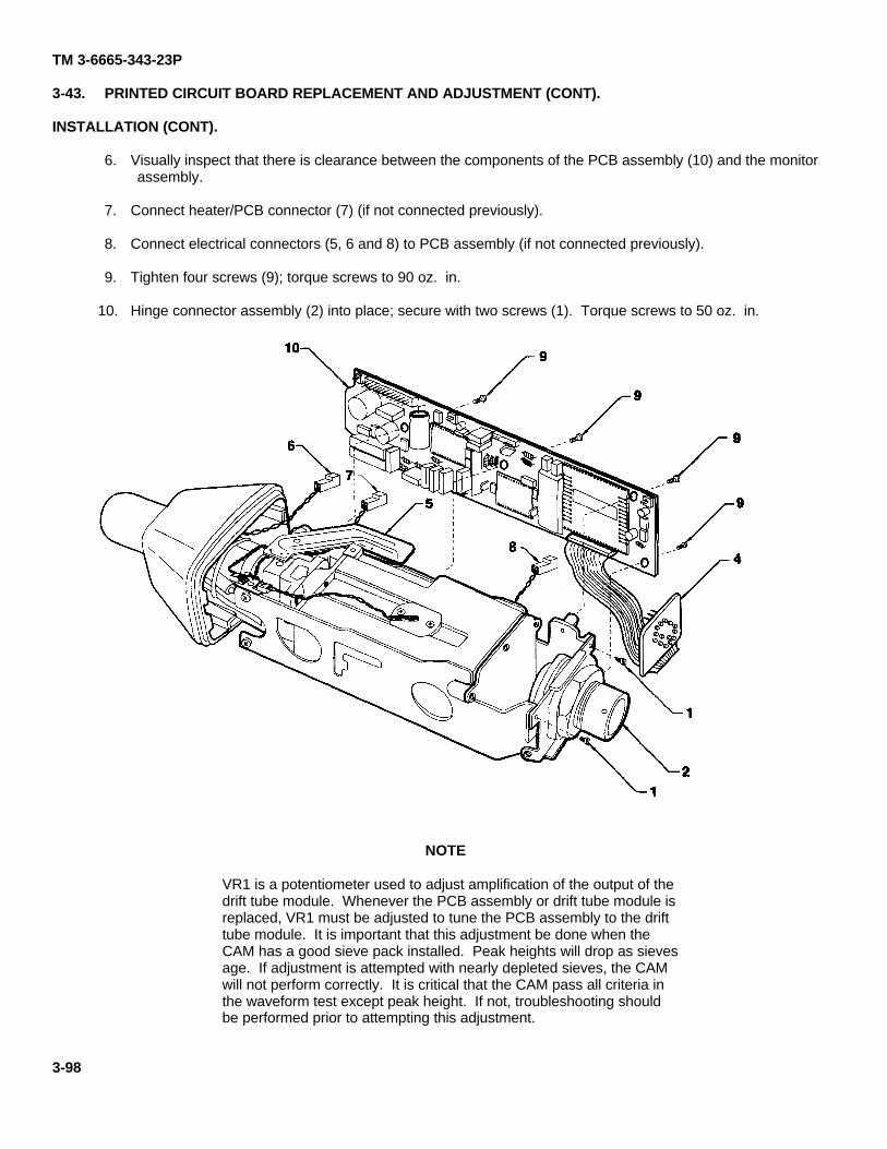
TM 3-6665-343-23P
3-43. PRINTED CIRCUIT BOARD REPLACEMENT AND ADJUSTMENT (CONT).
INSTALLATION (CONT).
6. Visually inspect that there is clearance between the components of the PCB assembly (10) and the monitorassembly.
7. Connect heater/PCB connector (7) (if not connected previously).
8. Connect electrical connectors (5, 6 and 8) to PCB assembly (if not connected previously).
9. Tighten four screws (9); torque screws to 90 oz. in.
10. Hinge connector assembly (2) into place; secure with two screws (1). Torque screws to 50 oz. in.
NOTE
VR1 is a potentiometer used to adjust amplification of the output of thedrift tube module. Whenever the PCB assembly or drift tube module isreplaced, VR1 must be adjusted to tune the PCB assembly to the drifttube module. It is important that this adjustment be done when theCAM has a good sieve pack installed. Peak heights will drop as sievesage. If adjustment is attempted with nearly depleted sieves, the CAMwill not perform correctly. It is critical that the CAM pass all criteria inthe waveform test except peak height. If not, troubleshooting shouldbe performed prior to attempting this adjustment.
3-98
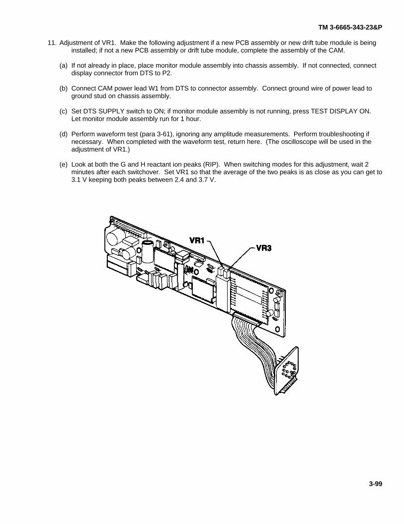
TM 3-6665-343-23&P
11. Adjustment of VR1. Make the following adjustment if a new PCB assembly or new drift tube module is beinginstalled; if not a new PCB assembly or drift tube module, complete the assembly of the CAM.
(a) If not already in place, place monitor module assembly into chassis assembly. If not connected, connectdisplay connector from DTS to P2.
(b) Connect CAM power lead W1 from DTS to connector assembly. Connect ground wire of power lead toground stud on chassis assembly.
(c) Set DTS SUPPLY switch to ON; if monitor module assembly is not running, press TEST DISPLAY ON.Let monitor module assembly run for 1 hour.
(d) Perform waveform test (para 3-61), ignoring any amplitude measurements. Perform troubleshooting ifnecessary. When completed with the waveform test, return here. (The oscilloscope will be used in theadjustment of VR1.)
(e) Look at both the G and H reactant ion peaks (RIP). When switching modes for this adjustment, wait 2minutes after each switchover. Set VR1 so that the average of the two peaks is as close as you can get to3.1 V keeping both peaks between 2.4 and 3.7 V.
3-99
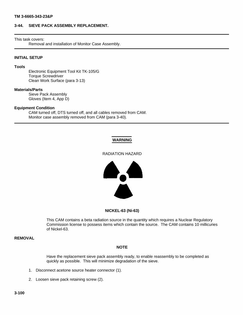
TM 3-6665-343-23&P
3-44. SIEVE PACK ASSEMBLY REPLACEMENT.
This task covers:Removal and installation of Monitor Case Assembly.
INITIAL SETUP
ToolsElectronic Equipment Tool Kit TK-105/GTorque ScrewdriverClean Work Surface (para 3-13)
Materials/PartsSieve Pack AssemblyGloves (Item 4, App D)
Equipment ConditionCAM turned off, DTS turned off, and all cables removed from CAM.Monitor case assembly removed from CAM (para 3-40).
WARNING
RADIATION HAZARD
NICKEL-63 (Ni-63)
This CAM contains a beta radiation source in the quantity which requires a Nuclear RegulatoryCommission license to possess items which contain the source. The CAM contains 10 millicuriesof Nickel-63.
REMOVAL
NOTE
Have the replacement sieve pack assembly ready, to enable reassembly to be completed asquickly as possible. This will minimize degradation of the sieve.
1. Disconnect acetone source heater connector (1).
2. Loosen sieve pack retaining screw (2).
3-100
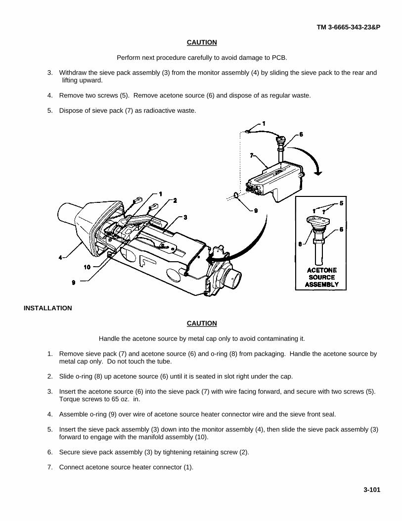
TM 3-6665-343-23&P
CAUTION
Perform next procedure carefully to avoid damage to PCB.
3. Withdraw the sieve pack assembly (3) from the monitor assembly (4) by sliding the sieve pack to the rear andlifting upward.
4. Remove two screws (5). Remove acetone source (6) and dispose of as regular waste.
5. Dispose of sieve pack (7) as radioactive waste.
INSTALLATION
CAUTION
Handle the acetone source by metal cap only to avoid contaminating it.
1. Remove sieve pack (7) and acetone source (6) and o-ring (8) from packaging. Handle the acetone source bymetal cap only. Do not touch the tube.
2. Slide o-ring (8) up acetone source (6) until it is seated in slot right under the cap.
3. Insert the acetone source (6) into the sieve pack (7) with wire facing forward, and secure with two screws (5).Torque screws to 65 oz. in.
4. Assemble o-ring (9) over wire of acetone source heater connector wire and the sieve front seal.
5. Insert the sieve pack assembly (3) down into the monitor assembly (4), then slide the sieve pack assembly (3)forward to engage with the manifold assembly (10).
6. Secure sieve pack assembly (3) by tightening retaining screw (2).
7. Connect acetone source heater connector (1).
3-101
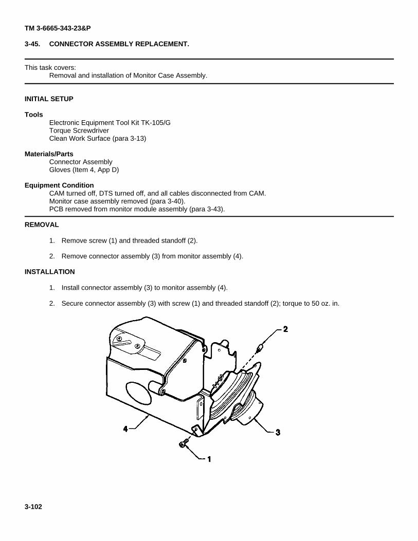
TM 3-6665-343-23&P
3-45. CONNECTOR ASSEMBLY REPLACEMENT.
This task covers:Removal and installation of Monitor Case Assembly.
INITIAL SETUP
ToolsElectronic Equipment Tool Kit TK-105/GTorque ScrewdriverClean Work Surface (para 3-13)
Materials/PartsConnector AssemblyGloves (Item 4, App D)
Equipment ConditionCAM turned off, DTS turned off, and all cables disconnected from CAM.Monitor case assembly removed (para 3-40).PCB removed from monitor module assembly (para 3-43).
REMOVAL
1. Remove screw (1) and threaded standoff (2).
2. Remove connector assembly (3) from monitor assembly (4).
INSTALLATION
1. Install connector assembly (3) to monitor assembly (4).
2. Secure connector assembly (3) with screw (1) and threaded standoff (2); torque to 50 oz. in.
3-102
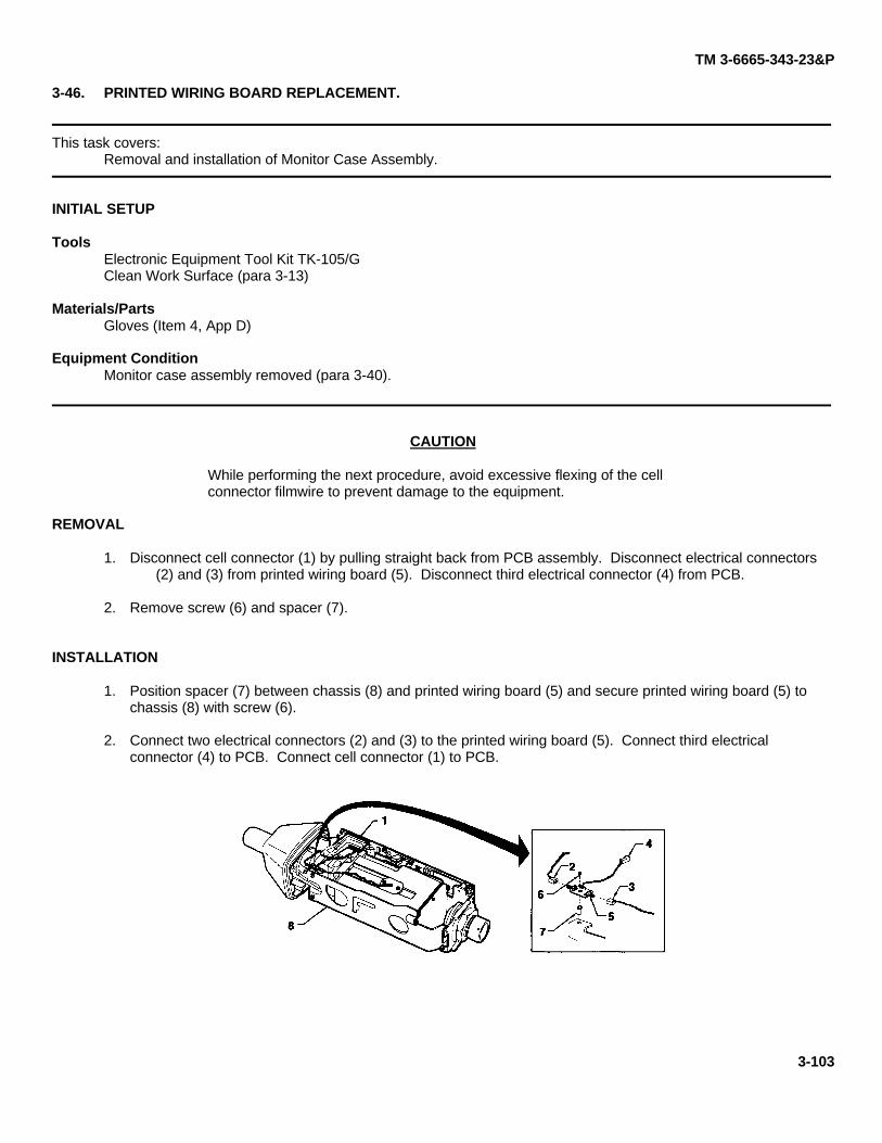
TM 3-6665-343-23&P
3-46. PRINTED WIRING BOARD REPLACEMENT.
This task covers:Removal and installation of Monitor Case Assembly.
INITIAL SETUP
ToolsElectronic Equipment Tool Kit TK-105/GClean Work Surface (para 3-13)
Materials/PartsGloves (Item 4, App D)
Equipment ConditionMonitor case assembly removed (para 3-40).
CAUTION
While performing the next procedure, avoid excessive flexing of the cellconnector filmwire to prevent damage to the equipment.
REMOVAL
1. Disconnect cell connector (1) by pulling straight back from PCB assembly. Disconnect electrical connectors(2) and (3) from printed wiring board (5). Disconnect third electrical connector (4) from PCB.
2. Remove screw (6) and spacer (7).
INSTALLATION
1. Position spacer (7) between chassis (8) and printed wiring board (5) and secure printed wiring board (5) tochassis (8) with screw (6).
2. Connect two electrical connectors (2) and (3) to the printed wiring board (5). Connect third electricalconnector (4) to PCB. Connect cell connector (1) to PCB.
3-103
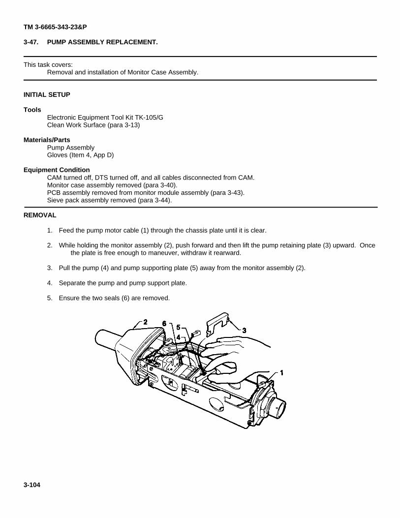
TM 3-6665-343-23&P
3-47. PUMP ASSEMBLY REPLACEMENT.
This task covers:Removal and installation of Monitor Case Assembly.
INITIAL SETUP
ToolsElectronic Equipment Tool Kit TK-105/GClean Work Surface (para 3-13)
Materials/PartsPump AssemblyGloves (Item 4, App D)
Equipment ConditionCAM turned off, DTS turned off, and all cables disconnected from CAM.Monitor case assembly removed (para 3-40).PCB assembly removed from monitor module assembly (para 3-43).Sieve pack assembly removed (para 3-44).
REMOVAL
1. Feed the pump motor cable (1) through the chassis plate until it is clear.
2. While holding the monitor assembly (2), push forward and then lift the pump retaining plate (3) upward. Oncethe plate is free enough to maneuver, withdraw it rearward.
3. Pull the pump (4) and pump supporting plate (5) away from the monitor assembly (2).
4. Separate the pump and pump support plate.
5. Ensure the two seals (6) are removed.
3-104
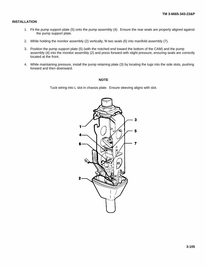
TM 3-6665-343-23&P
INSTALLATION
1. Fit the pump support plate (5) onto the pump assembly (4). Ensure the rear seals are properly aligned againstthe pump support plate.
2. While holding the monitor assembly (2) vertically, fit two seals (6) into manifold assembly (7).
3. Position the pump support plate (5) (with the notched end toward the bottom of the CAM) and the pumpassembly (4) into the monitor assembly (2) and press forward with slight pressure, ensuring seals are correctlylocated at the front.
4. While maintaining pressure, install the pump retaining plate (3) by locating the lugs into the side slots, pushingforward and then downward.
NOTE
Tuck wiring into L slot in chassis plate. Ensure sleeving aligns with slot.
3-105
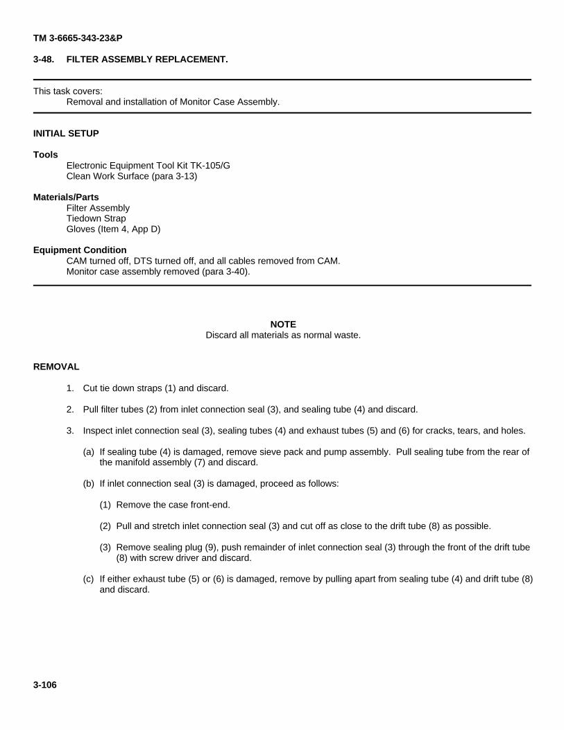
TM 3-6665-343-23&P
3-48. FILTER ASSEMBLY REPLACEMENT.
This task covers:Removal and installation of Monitor Case Assembly.
INITIAL SETUP
ToolsElectronic Equipment Tool Kit TK-105/GClean Work Surface (para 3-13)
Materials/PartsFilter AssemblyTiedown StrapGloves (Item 4, App D)
Equipment ConditionCAM turned off, DTS turned off, and all cables removed from CAM.Monitor case assembly removed (para 3-40).
NOTEDiscard all materials as normal waste.
REMOVAL
1. Cut tie down straps (1) and discard.
2. Pull filter tubes (2) from inlet connection seal (3), and sealing tube (4) and discard.
3. Inspect inlet connection seal (3), sealing tubes (4) and exhaust tubes (5) and (6) for cracks, tears, and holes.
(a) If sealing tube (4) is damaged, remove sieve pack and pump assembly. Pull sealing tube from the rear ofthe manifold assembly (7) and discard.
(b) If inlet connection seal (3) is damaged, proceed as follows:
(1) Remove the case front-end.
(2) Pull and stretch inlet connection seal (3) and cut off as close to the drift tube (8) as possible.
(3) Remove sealing plug (9), push remainder of inlet connection seal (3) through the front of the drift tube(8) with screw driver and discard.
(c) If either exhaust tube (5) or (6) is damaged, remove by pulling apart from sealing tube (4) and drift tube (8)and discard.
3-106
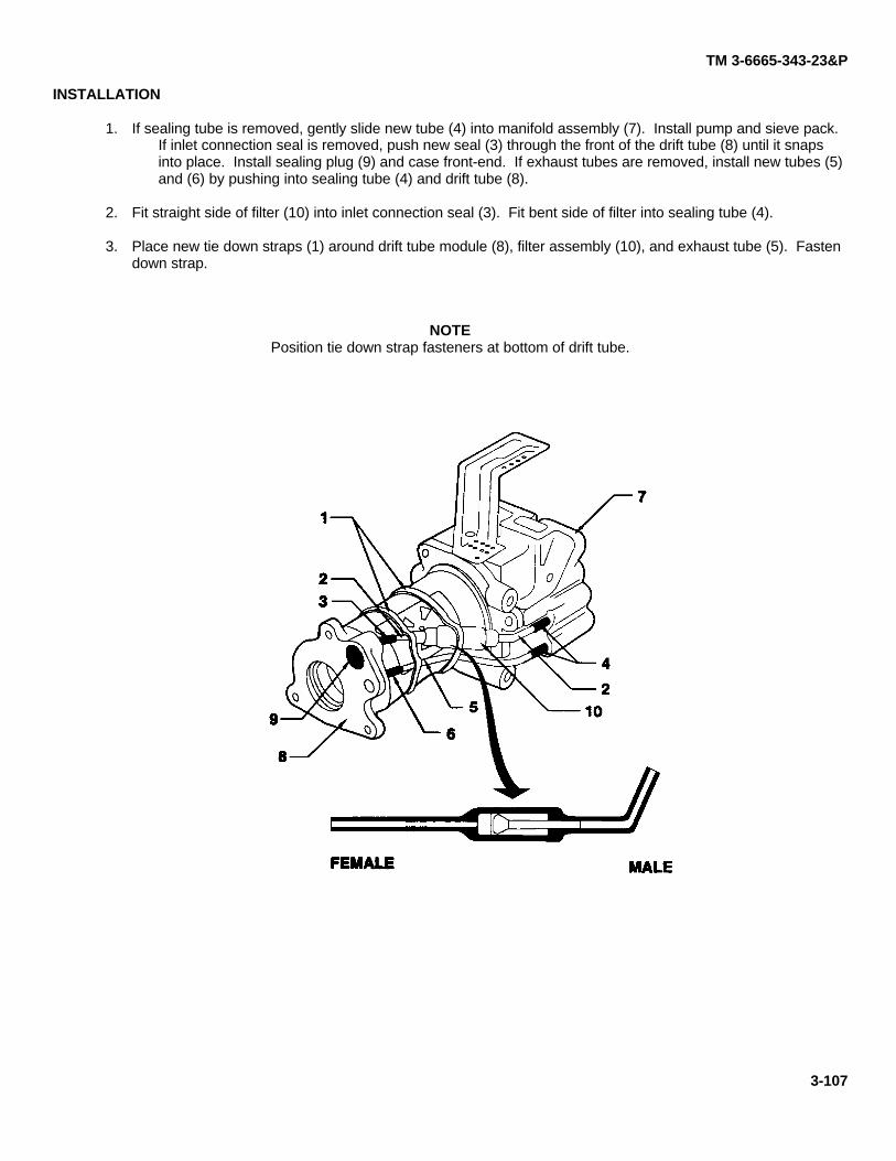
TM 3-6665-343-23&P
INSTALLATION
1. If sealing tube is removed, gently slide new tube (4) into manifold assembly (7). Install pump and sieve pack.If inlet connection seal is removed, push new seal (3) through the front of the drift tube (8) until it snapsinto place. Install sealing plug (9) and case front-end. If exhaust tubes are removed, install new tubes (5)and (6) by pushing into sealing tube (4) and drift tube (8).
2. Fit straight side of filter (10) into inlet connection seal (3). Fit bent side of filter into sealing tube (4).
3. Place new tie down straps (1) around drift tube module (8), filter assembly (10), and exhaust tube (5). Fastendown strap.
NOTEPosition tie down strap fasteners at bottom of drift tube.
3-107
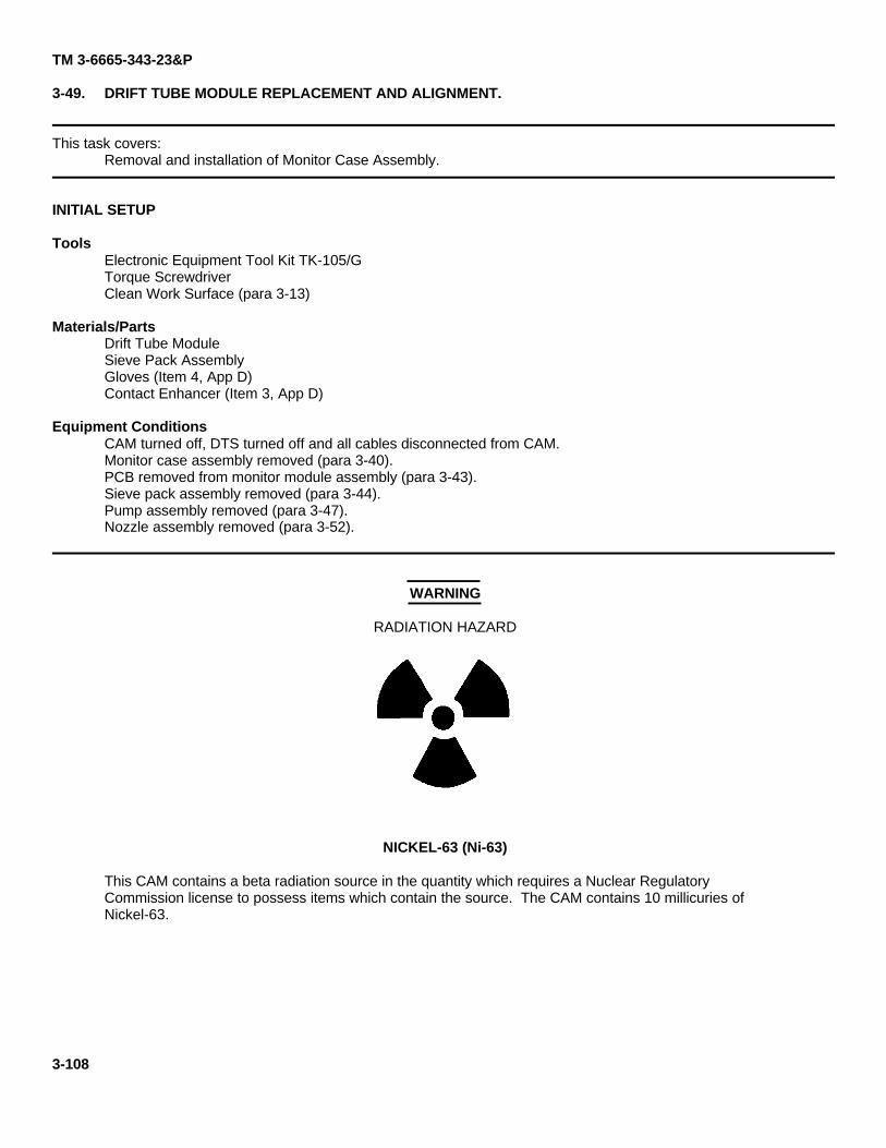
TM 3-6665-343-23&P
3-49. DRIFT TUBE MODULE REPLACEMENT AND ALIGNMENT.
This task covers:Removal and installation of Monitor Case Assembly.
INITIAL SETUP
ToolsElectronic Equipment Tool Kit TK-105/GTorque ScrewdriverClean Work Surface (para 3-13)
Materials/PartsDrift Tube ModuleSieve Pack AssemblyGloves (Item 4, App D)Contact Enhancer (Item 3, App D)
Equipment ConditionsCAM turned off, DTS turned off and all cables disconnected from CAM.Monitor case assembly removed (para 3-40).PCB removed from monitor module assembly (para 3-43).Sieve pack assembly removed (para 3-44).Pump assembly removed (para 3-47).Nozzle assembly removed (para 3-52).
WARNING
RADIATION HAZARD
NICKEL-63 (Ni-63)
This CAM contains a beta radiation source in the quantity which requires a Nuclear RegulatoryCommission license to possess items which contain the source. The CAM contains 10 millicuries ofNickel-63.
3-108
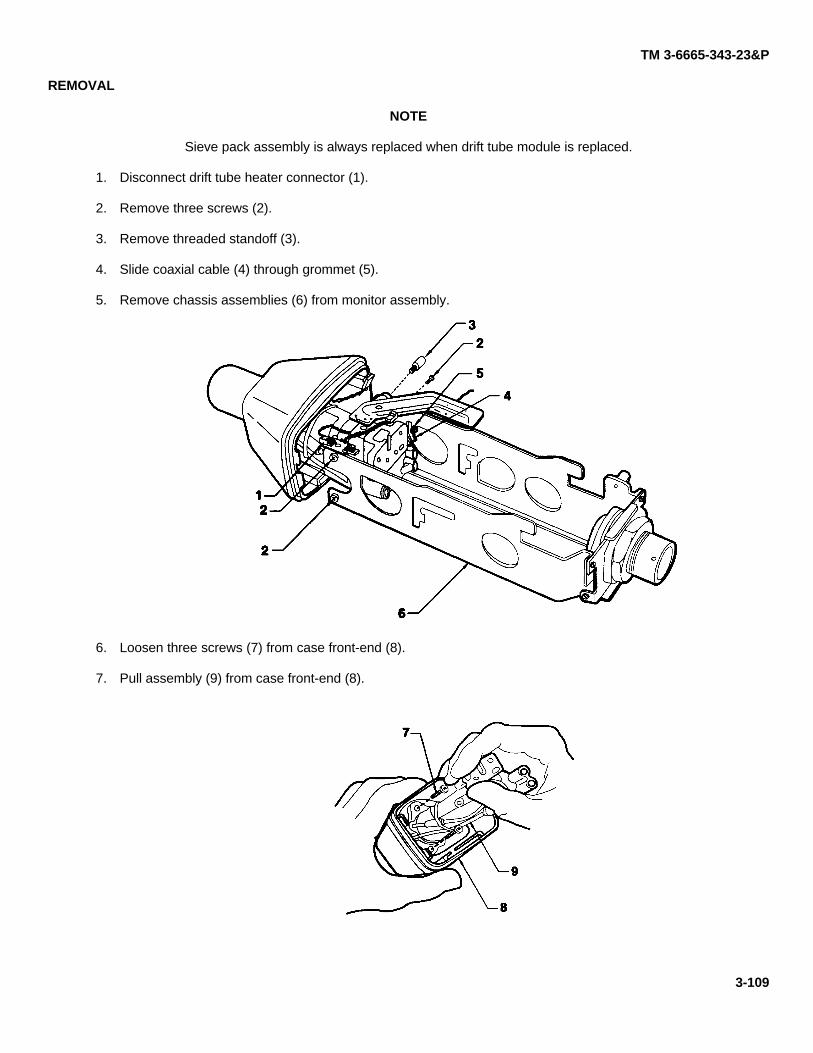
TM 3-6665-343-23&P
REMOVAL
NOTE
Sieve pack assembly is always replaced when drift tube module is replaced.
1. Disconnect drift tube heater connector (1).
2. Remove three screws (2).
3. Remove threaded standoff (3).
4. Slide coaxial cable (4) through grommet (5).
5. Remove chassis assemblies (6) from monitor assembly.
6. Loosen three screws (7) from case front-end (8).
7. Pull assembly (9) from case front-end (8).
3-109
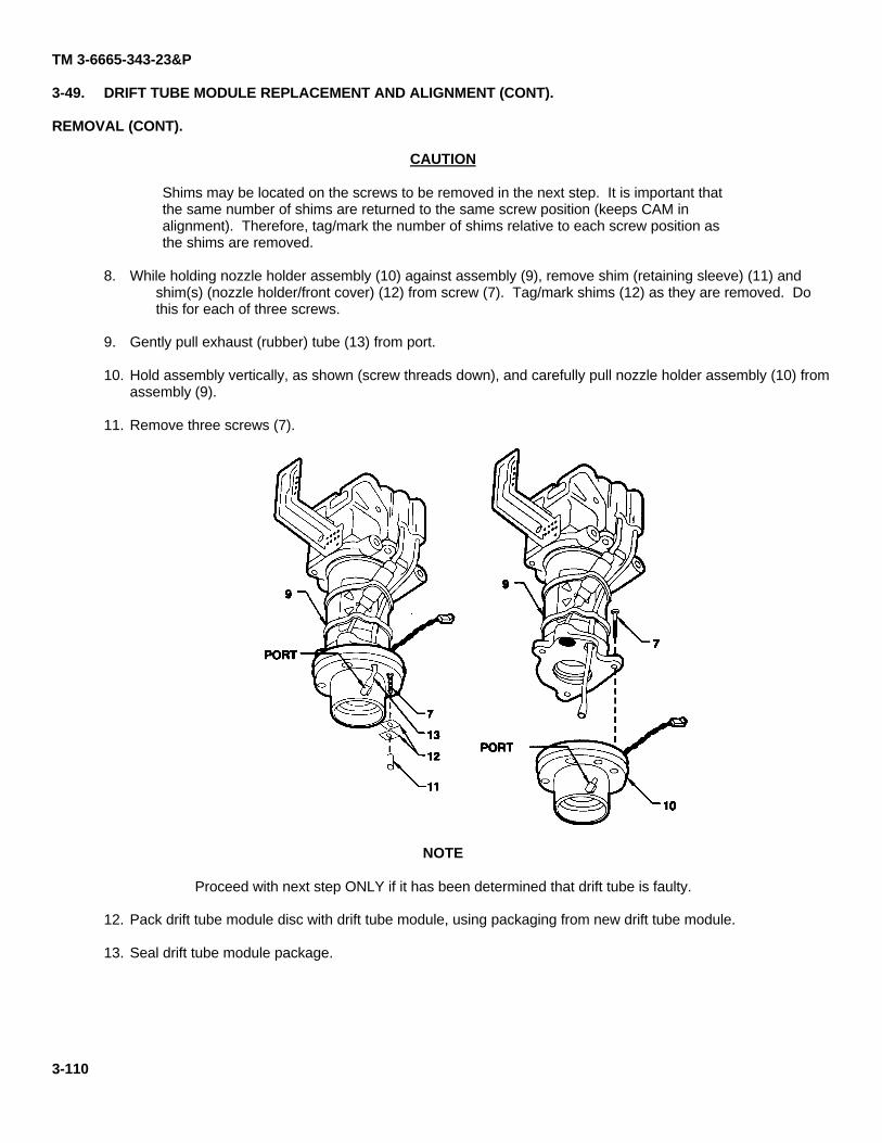
TM 3-6665-343-23&P
3-49. DRIFT TUBE MODULE REPLACEMENT AND ALIGNMENT (CONT).
REMOVAL (CONT).
CAUTION
Shims may be located on the screws to be removed in the next step. It is important thatthe same number of shims are returned to the same screw position (keeps CAM inalignment). Therefore, tag/mark the number of shims relative to each screw position asthe shims are removed.
8. While holding nozzle holder assembly (10) against assembly (9), remove shim (retaining sleeve) (11) andshim(s) (nozzle holder/front cover) (12) from screw (7). Tag/mark shims (12) as they are removed. Dothis for each of three screws.
9. Gently pull exhaust (rubber) tube (13) from port.
10. Hold assembly vertically, as shown (screw threads down), and carefully pull nozzle holder assembly (10) fromassembly (9).
11. Remove three screws (7).
NOTE
Proceed with next step ONLY if it has been determined that drift tube is faulty.
12. Pack drift tube module disc with drift tube module, using packaging from new drift tube module.
13. Seal drift tube module package.
3-110
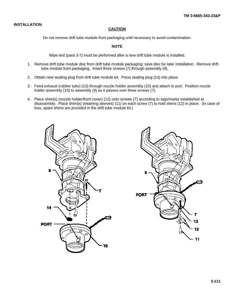
TM 3-6665-343-23&P
INSTALLATIONCAUTION
Do not remove drift tube module from packaging until necessary to avoid contamination.
NOTE
Wipe test (para 3-7) must be performed after a new drift tube module is installed.
1. Remove drift tube module disc from drift tube module packaging; save disc for later installation. Remove drifttube module from packaging. Insert three screws (7) through assembly (9).
2. Obtain new sealing plug from drift tube module kit. Press sealing plug (14) into place.
3. Feed exhaust (rubber tube) (13) through nozzle holder assembly (10) and attach to port. Position nozzleholder assembly (10) to assembly (9) as it passes over three screws (7).
4. Place shim(s) (nozzle holder/front cover) (12) onto screws (7) according to tags/marks established atdisassembly. Place shim(s) (retaining sleeves) (11) on each screw (7) to hold shims (12) in place. (In case ofloss, spare shims are provided in the drift tube module kit.)
3-111
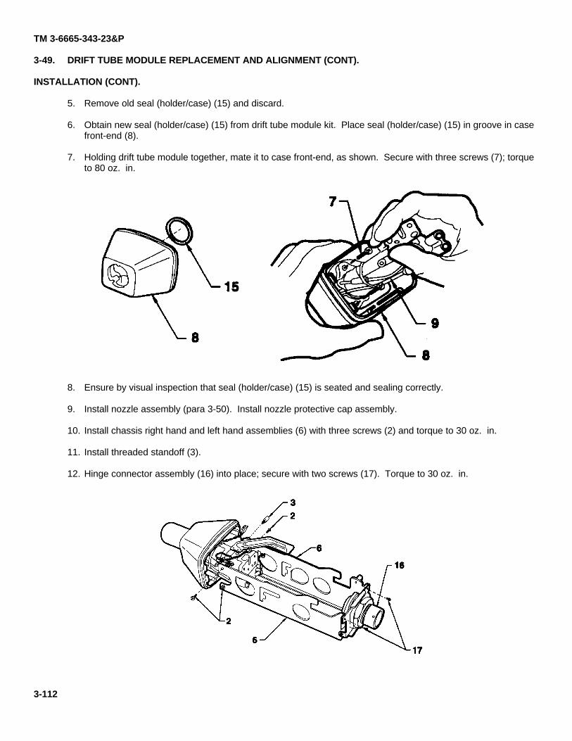
TM 3-6665-343-23&P
3-49. DRIFT TUBE MODULE REPLACEMENT AND ALIGNMENT (CONT).
INSTALLATION (CONT).
5. Remove old seal (holder/case) (15) and discard.
6. Obtain new seal (holder/case) (15) from drift tube module kit. Place seal (holder/case) (15) in groove in casefront-end (8).
7. Holding drift tube module together, mate it to case front-end, as shown. Secure with three screws (7); torqueto 80 oz. in.
8. Ensure by visual inspection that seal (holder/case) (15) is seated and sealing correctly.
9. Install nozzle assembly (para 3-50). Install nozzle protective cap assembly.
10. Install chassis right hand and left hand assemblies (6) with three screws (2) and torque to 30 oz. in.
11. Install threaded standoff (3).
12. Hinge connector assembly (16) into place; secure with two screws (17). Torque to 30 oz. in.
3-112
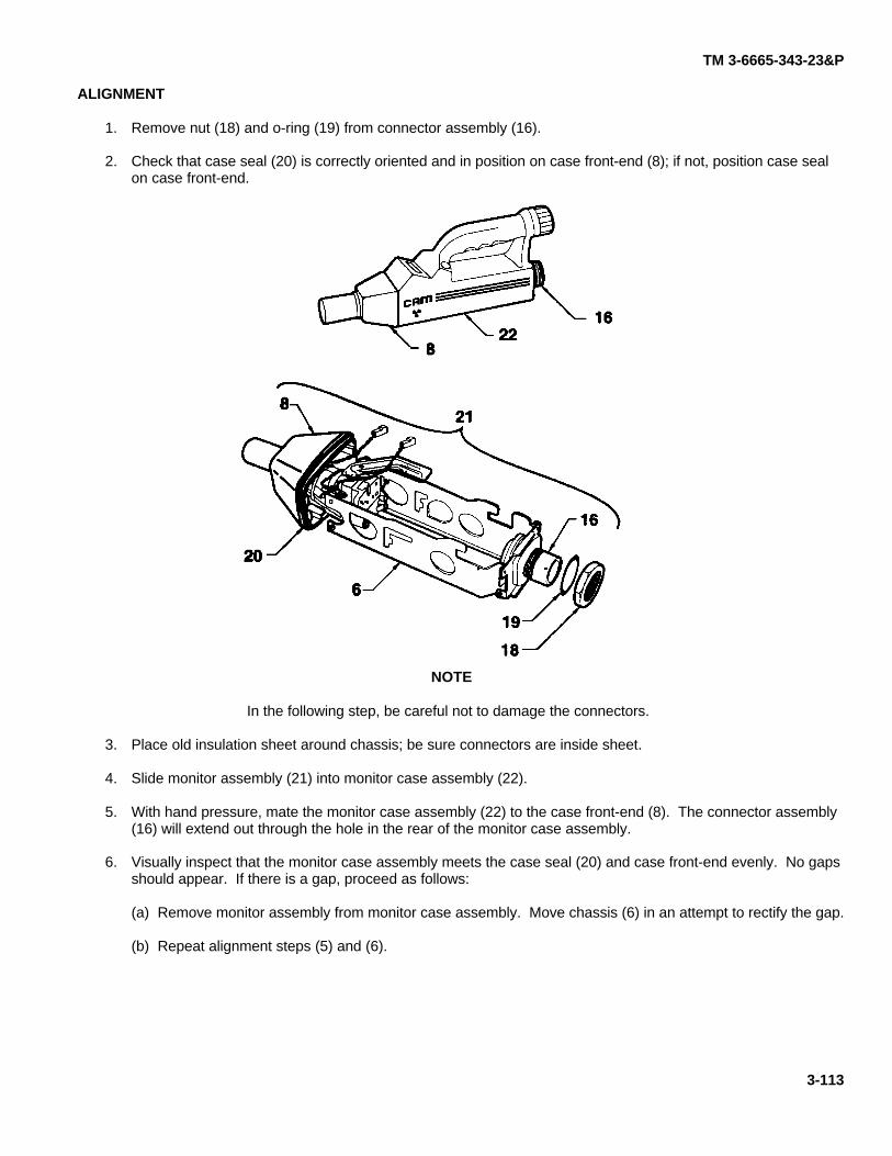
TM 3-6665-343-23&P
ALIGNMENT
1. Remove nut (18) and o-ring (19) from connector assembly (16).
2. Check that case seal (20) is correctly oriented and in position on case front-end (8); if not, position case sealon case front-end.
NOTE
In the following step, be careful not to damage the connectors.
3. Place old insulation sheet around chassis; be sure connectors are inside sheet.
4. Slide monitor assembly (21) into monitor case assembly (22).
5. With hand pressure, mate the monitor case assembly (22) to the case front-end (8). The connector assembly(16) will extend out through the hole in the rear of the monitor case assembly.
6. Visually inspect that the monitor case assembly meets the case seal (20) and case front-end evenly. No gapsshould appear. If there is a gap, proceed as follows:
(a) Remove monitor assembly from monitor case assembly. Move chassis (6) in an attempt to rectify the gap.
(b) Repeat alignment steps (5) and (6).
3-113
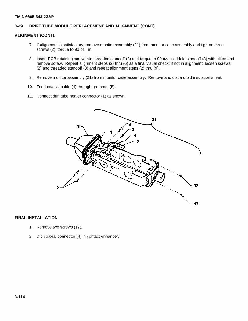
TM 3-6665-343-23&P
3-49. DRIFT TUBE MODULE REPLACEMENT AND ALIGNMENT (CONT).
ALIGNMENT (CONT).
7. If alignment is satisfactory, remove monitor assembly (21) from monitor case assembly and tighten threescrews (2); torque to 90 oz. in.
8. Insert PCB retaining screw into threaded standoff (3) and torque to 90 oz. in. Hold standoff (3) with pliers andremove screw. Repeat alignment steps (2) thru (6) as a final visual check; if not in alignment, loosen screws(2) and threaded standoff (3) and repeat alignment steps (2) thru (9).
9. Remove monitor assembly (21) from monitor case assembly. Remove and discard old insulation sheet.
10. Feed coaxial cable (4) through grommet (5).
11. Connect drift tube heater connector (1) as shown.
FINAL INSTALLATION
1. Remove two screws (17).
2. Dip coaxial connector (4) in contact enhancer.
3-114
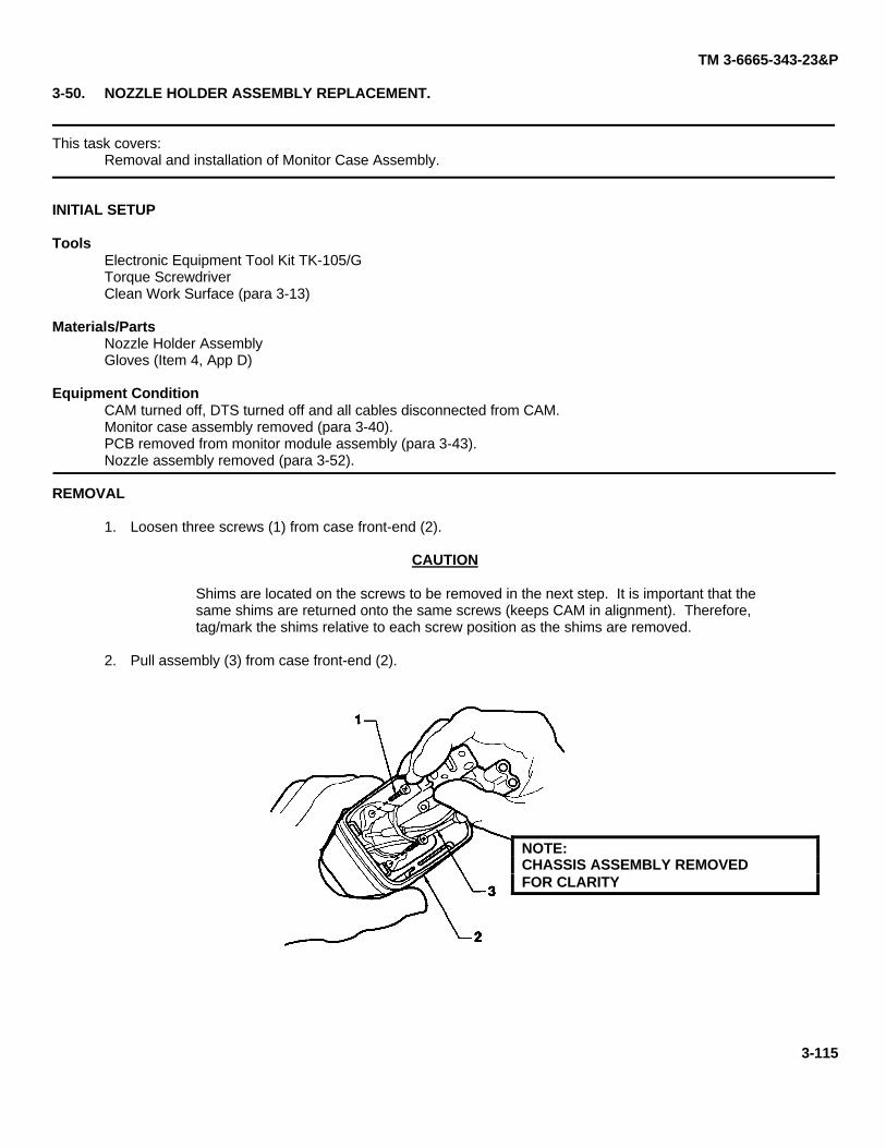
TM 3-6665-343-23&P
3-50. NOZZLE HOLDER ASSEMBLY REPLACEMENT.
This task covers:Removal and installation of Monitor Case Assembly.
INITIAL SETUP
ToolsElectronic Equipment Tool Kit TK-105/GTorque ScrewdriverClean Work Surface (para 3-13)
Materials/PartsNozzle Holder AssemblyGloves (Item 4, App D)
Equipment ConditionCAM turned off, DTS turned off and all cables disconnected from CAM.Monitor case assembly removed (para 3-40).PCB removed from monitor module assembly (para 3-43).Nozzle assembly removed (para 3-52).
REMOVAL
1. Loosen three screws (1) from case front-end (2).
CAUTION
Shims are located on the screws to be removed in the next step. It is important that thesame shims are returned onto the same screws (keeps CAM in alignment). Therefore,tag/mark the shims relative to each screw position as the shims are removed.
2. Pull assembly (3) from case front-end (2).
NOTE:CHASSIS ASSEMBLY REMOVEDFOR CLARITY
3-115
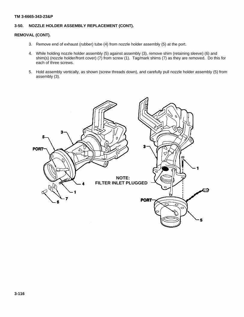
TM 3-6665-343-23&P
3-50. NOZZLE HOLDER ASSEMBLY REPLACEMENT (CONT).
REMOVAL (CONT).
3. Remove end of exhaust (rubber) tube (4) from nozzle holder assembly (5) at the port.
4. While holding nozzle holder assembly (5) against assembly (3), remove shim (retaining sleeve) (6) andshim(s) (nozzle holder/front cover) (7) from screw (1). Tag/mark shims (7) as they are removed. Do this foreach of three screws.
5. Hold assembly vertically, as shown (screw threads down), and carefully pull nozzle holder assembly (5) fromassembly (3).
NOTE:FILTER INLET PLUGGED
3-116
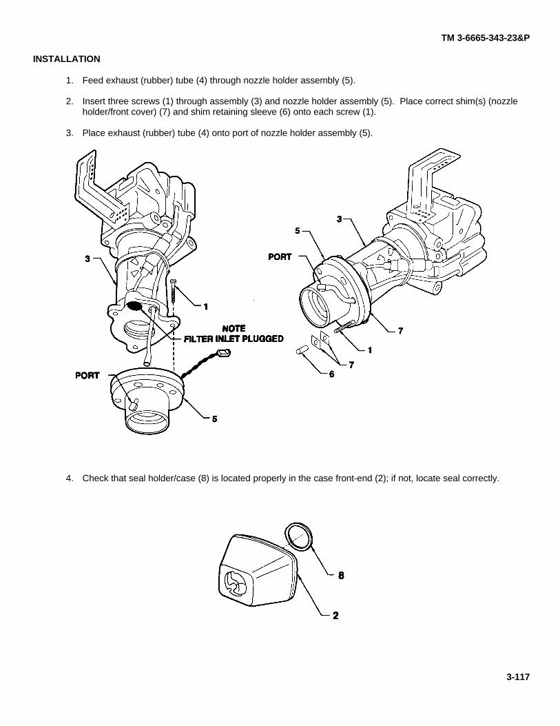
TM 3-6665-343-23&P
INSTALLATION
1. Feed exhaust (rubber) tube (4) through nozzle holder assembly (5).
2. Insert three screws (1) through assembly (3) and nozzle holder assembly (5). Place correct shim(s) (nozzleholder/front cover) (7) and shim retaining sleeve (6) onto each screw (1).
3. Place exhaust (rubber) tube (4) onto port of nozzle holder assembly (5).
4. Check that seal holder/case (8) is located properly in the case front-end (2); if not, locate seal correctly.
3-117
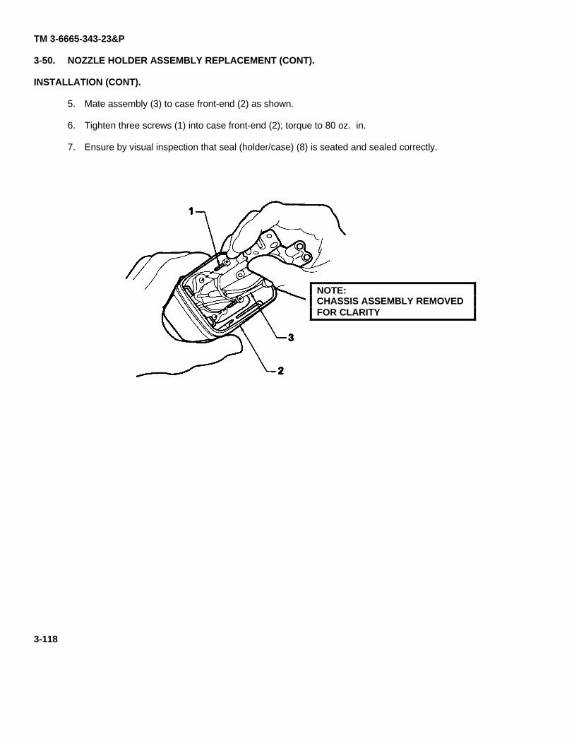
TM 3-6665-343-23&P
3-50. NOZZLE HOLDER ASSEMBLY REPLACEMENT (CONT).
INSTALLATION (CONT).
5. Mate assembly (3) to case front-end (2) as shown.
6. Tighten three screws (1) into case front-end (2); torque to 80 oz. in.
7. Ensure by visual inspection that seal (holder/case) (8) is seated and sealed correctly.
NOTE:CHASSIS ASSEMBLY REMOVEDFOR CLARITY
3-118
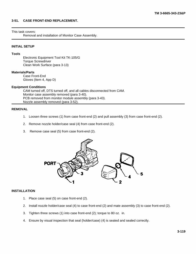
TM 3-6665-343-23&P
3-51. CASE FRONT-END REPLACEMENT.
This task covers:Removal and installation of Monitor Case Assembly.
INITIAL SETUP
ToolsElectronic Equipment Tool Kit TK-105/GTorque ScrewdriverClean Work Surface (para 3-13)
Materials/PartsCase Front-EndGloves (Item 4, App D)
Equipment ConditionsCAM turned off, DTS turned off, and all cables disconnected from CAM.Monitor case assembly removed (para 3-40).PCB removed from monitor module assembly (para 3-43).Nozzle assembly removed (para 3-52).
REMOVAL
1. Loosen three screws (1) from case front-end (2) and pull assembly (3) from case front-end (2).
2. Remove nozzle holder/case seal (4) from case front-end (2).
3. Remove case seal (5) from case front-end (2).
INSTALLATION
1. Place case seal (5) on case front-end (2).
2. Install nozzle holder/case seal (4) to case front-end (2) and mate assembly (3) to case front-end (2).
3. Tighten three screws (1) into case front-end (2); torque to 80 oz. in.
4. Ensure by visual inspection that seal (holder/case) (4) is seated and sealed correctly.
3-119
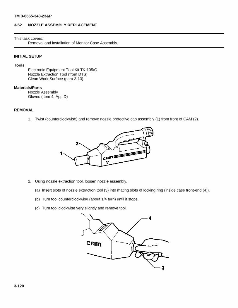
TM 3-6665-343-23&P
3-52. NOZZLE ASSEMBLY REPLACEMENT.
This task covers:Removal and installation of Monitor Case Assembly.
INITIAL SETUP
ToolsElectronic Equipment Tool Kit TK-105/GNozzle Extraction Tool (from DTS)Clean Work Surface (para 3-13)
Materials/PartsNozzle AssemblyGloves (Item 4, App D)
REMOVAL
1. Twist (counterclockwise) and remove nozzle protective cap assembly (1) from front of CAM (2).
2. Using nozzle extraction tool, loosen nozzle assembly.
(a) Insert slots of nozzle extraction tool (3) into mating slots of locking ring (inside case front-end (4)).
(b) Turn tool counterclockwise (about 1/4 turn) until it stops.
(c) Turn tool clockwise very slightly and remove tool.
3-120
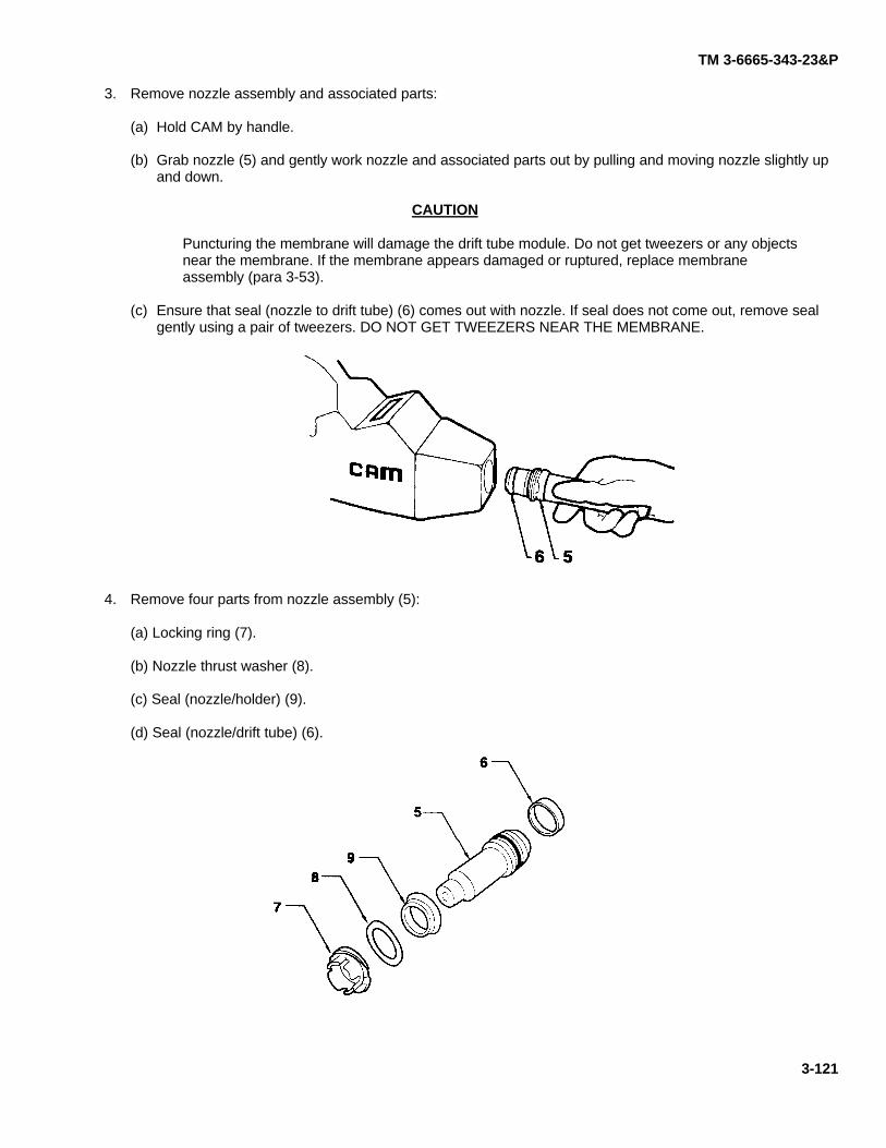
TM 3-6665-343-23&P
3. Remove nozzle assembly and associated parts:
(a) Hold CAM by handle.
(b) Grab nozzle (5) and gently work nozzle and associated parts out by pulling and moving nozzle slightly upand down.
CAUTION
Puncturing the membrane will damage the drift tube module. Do not get tweezers or any objectsnear the membrane. If the membrane appears damaged or ruptured, replace membraneassembly (para 3-53).
(c) Ensure that seal (nozzle to drift tube) (6) comes out with nozzle. If seal does not come out, remove sealgently using a pair of tweezers. DO NOT GET TWEEZERS NEAR THE MEMBRANE.
4. Remove four parts from nozzle assembly (5):
(a) Locking ring (7).
(b) Nozzle thrust washer (8).
(c) Seal (nozzle/holder) (9).
(d) Seal (nozzle/drift tube) (6).
3-121
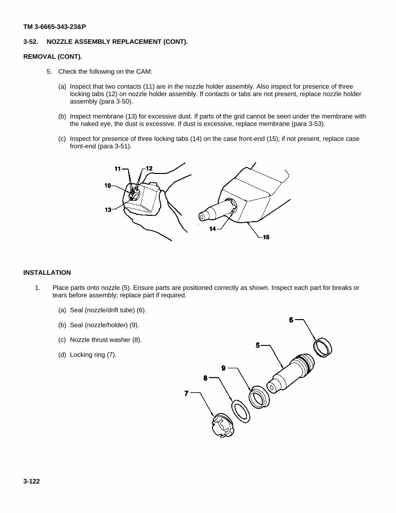
TM 3-6665-343-23&P
3-52. NOZZLE ASSEMBLY REPLACEMENT (CONT).
REMOVAL (CONT).
5. Check the following on the CAM:
(a) Inspect that two contacts (11) are in the nozzle holder assembly. Also inspect for presence of threelocking tabs (12) on nozzle holder assembly. If contacts or tabs are not present, replace nozzle holderassembly (para 3-50).
(b) Inspect membrane (13) for excessive dust. If parts of the grid cannot be seen under the membrane withthe naked eye, the dust is excessive. If dust is excessive, replace membrane (para 3-53).
(c) Inspect for presence of three locking tabs (14) on the case front-end (15); if not present, replace casefront-end (para 3-51).
INSTALLATION
1. Place parts onto nozzle (5). Ensure parts are positioned correctly as shown. Inspect each part for breaks ortears before assembly; replace part if required.
(a) Seal (nozzle/drift tube) (6).
(b) Seal (nozzle/holder) (9).
(c) Nozzle thrust washer (8).
(d) Locking ring (7).
3-122
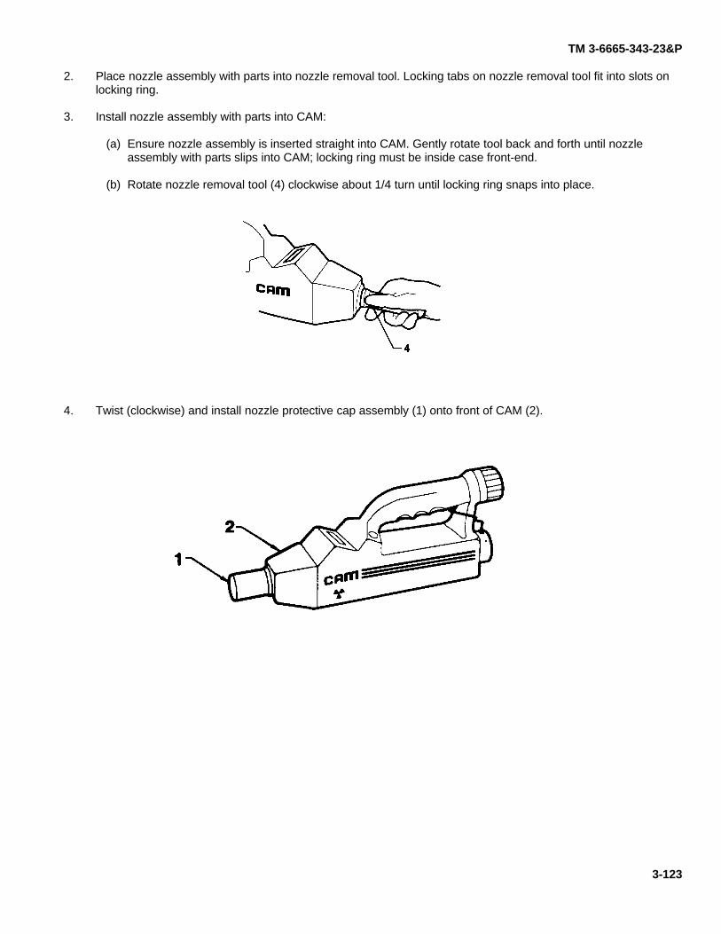
TM 3-6665-343-23&P
2. Place nozzle assembly with parts into nozzle removal tool. Locking tabs on nozzle removal tool fit into slots onlocking ring.
3. Install nozzle assembly with parts into CAM:
(a) Ensure nozzle assembly is inserted straight into CAM. Gently rotate tool back and forth until nozzleassembly with parts slips into CAM; locking ring must be inside case front-end.
(b) Rotate nozzle removal tool (4) clockwise about 1/4 turn until locking ring snaps into place.
4. Twist (clockwise) and install nozzle protective cap assembly (1) onto front of CAM (2).
3-123
TM 3-6665-343-23&P
3-53. MEMBRANE ASSEMBLY REPLACEMENT.
This task covers:Removal and installation of Monitor Case Assembly.
INITIAL SETUP
ToolsElectronic Equipment Tool Kit TK-1 05/GMembrane Extraction Tool (DTS Lid)Clean Work Surface (para 3-13)
Materials/PartsMembrane AssemblyGloves (Item 4, App D)
Equipment ConditionNozzle assembly removed (para 3-52).
WARNING
RADIATION HAZARD
NICKEL-63 (Ni-63)
This CAM contains a beta radiation source in the quantity which requires a Nuclear RegulatoryCommission license to possess items which contain the source. The CAM contains 10 millicuries ofNickel-63.
WARNING
Removal of the membrane assembly "opens" the pneumatically "sealed" drift tube module, thereforeindirectly exposing the Ni-63 ionizing source. To avoid exposure, minimize the time spent performing thistask. For further information on the Nuclear Regulatory Commission License, see Appendix E.
CAUTION
Removal of the membrane assembly exposes CAM's highly sensitive sensing device to outsidecontamination. Ensure that gloves are worn and appropriate precautions are taken to avoid equipmentcontamination. Avoid touching or getting gloves near membrane. A special membrane extraction tool isprovided in the DTS lid. DO NOT ATTEMPT TO USE ANY OTHER TOOL. The membrane extraction toolhas a built-in "stop" to avoid damaging the membrane; do not attempt to adjust or modify this tool.
3-124
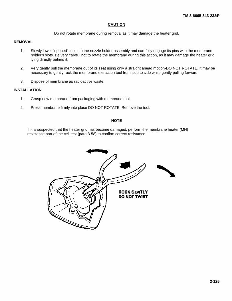
TM 3-6665-343-23&P
CAUTION
Do not rotate membrane during removal as it may damage the heater grid.
REMOVAL
1. Slowly lower "opened" tool into the nozzle holder assembly and carefully engage its pins with the membraneholder's slots. Be very careful not to rotate the membrane during this action, as it may damage the heater gridlying directly behind it.
2. Very gently pull the membrane out of its seat using only a straight ahead motion-DO NOT ROTATE. It may benecessary to gently rock the membrane extraction tool from side to side while gently pulling forward.
3. Dispose of membrane as radioactive waste.
INSTALLATION
1. Grasp new membrane from packaging with membrane tool.
2. Press membrane firmly into place DO NOT ROTATE. Remove the tool.
NOTE
If it is suspected that the heater grid has become damaged, perform the membrane heater (MH)resistance part of the cell test (para 3-58) to confirm correct resistance.
3-125
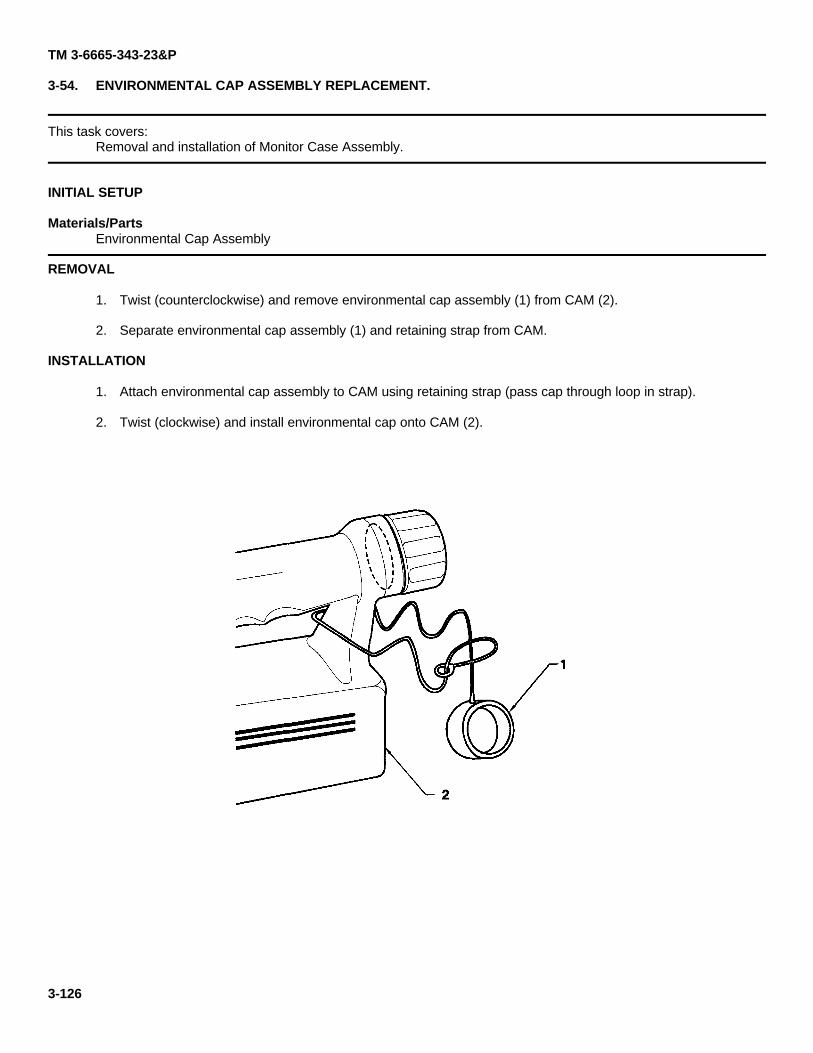
TM 3-6665-343-23&P
3-54. ENVIRONMENTAL CAP ASSEMBLY REPLACEMENT.
This task covers:Removal and installation of Monitor Case Assembly.
INITIAL SETUP
Materials/PartsEnvironmental Cap Assembly
REMOVAL
1. Twist (counterclockwise) and remove environmental cap assembly (1) from CAM (2).
2. Separate environmental cap assembly (1) and retaining strap from CAM.
INSTALLATION
1. Attach environmental cap assembly to CAM using retaining strap (pass cap through loop in strap).
2. Twist (clockwise) and install environmental cap onto CAM (2).
3-126
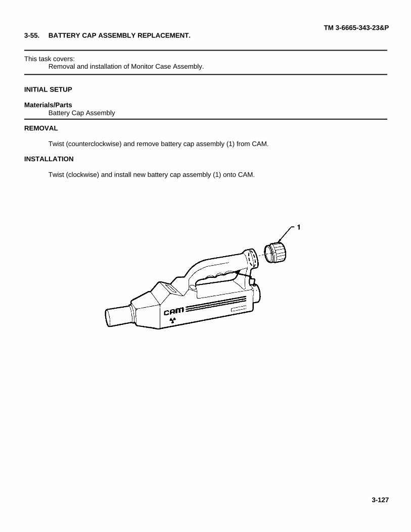
TM 3-6665-343-23&P3-55. BATTERY CAP ASSEMBLY REPLACEMENT.
This task covers:Removal and installation of Monitor Case Assembly.
INITIAL SETUP
Materials/PartsBattery Cap Assembly
REMOVAL
Twist (counterclockwise) and remove battery cap assembly (1) from CAM.
INSTALLATION
Twist (clockwise) and install new battery cap assembly (1) onto CAM.
3-127
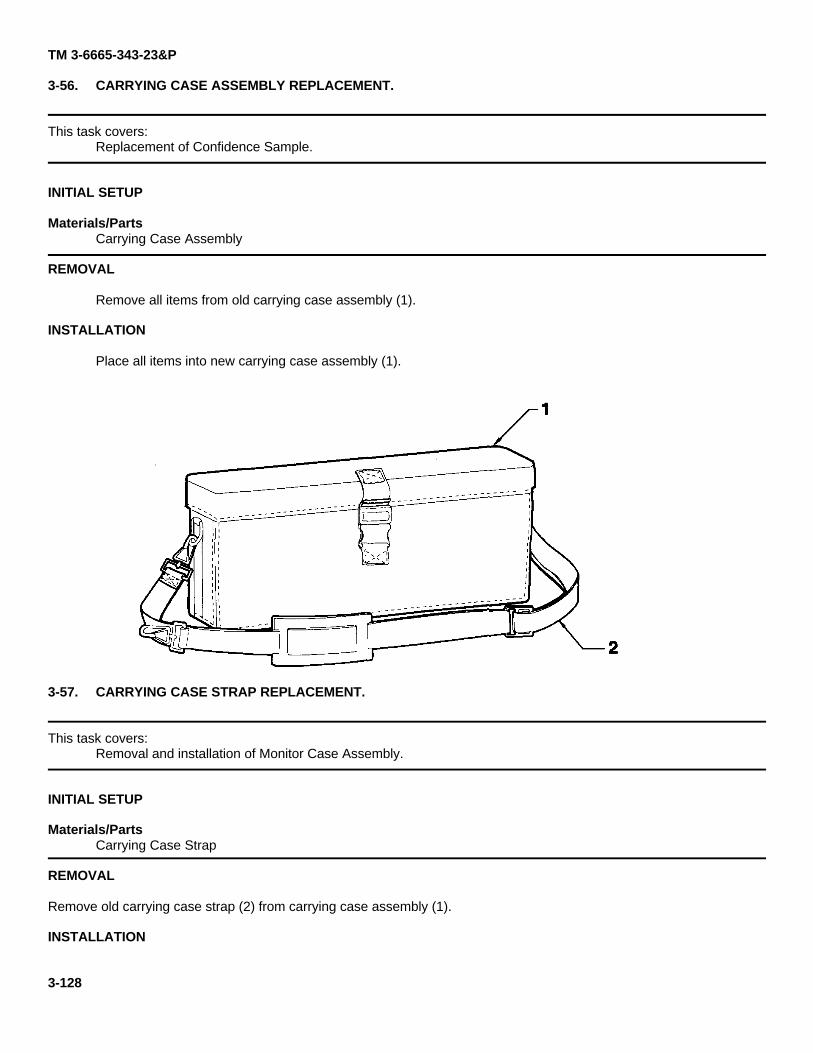
TM 3-6665-343-23&P
3-56. CARRYING CASE ASSEMBLY REPLACEMENT.
This task covers:Replacement of Confidence Sample.
INITIAL SETUP
Materials/PartsCarrying Case Assembly
REMOVAL
Remove all items from old carrying case assembly (1).
INSTALLATION
Place all items into new carrying case assembly (1).
3-57. CARRYING CASE STRAP REPLACEMENT.
This task covers:Removal and installation of Monitor Case Assembly.
INITIAL SETUP
Materials/PartsCarrying Case Strap
REMOVAL
Remove old carrying case strap (2) from carrying case assembly (1).
INSTALLATION
3-128
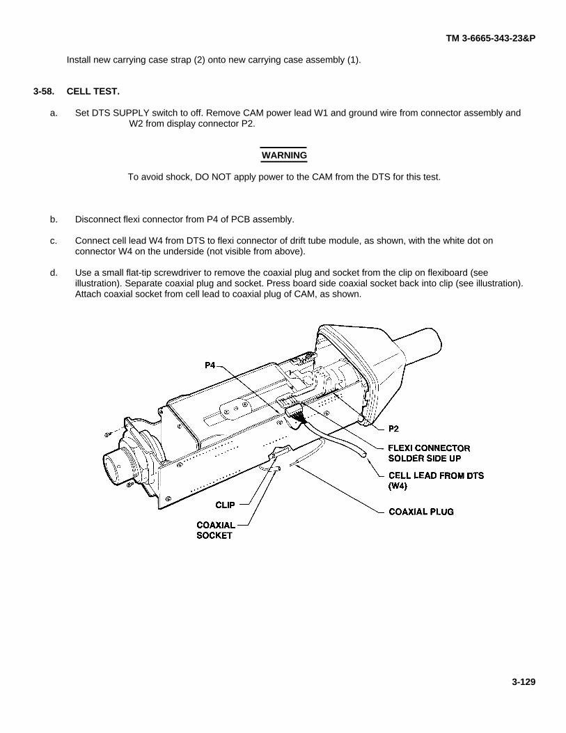
TM 3-6665-343-23&P
Install new carrying case strap (2) onto new carrying case assembly (1).
3-58. CELL TEST.
a. Set DTS SUPPLY switch to off. Remove CAM power lead W1 and ground wire from connector assembly andW2 from display connector P2.
WARNING
To avoid shock, DO NOT apply power to the CAM from the DTS for this test.
b. Disconnect flexi connector from P4 of PCB assembly.
c. Connect cell lead W4 from DTS to flexi connector of drift tube module, as shown, with the white dot onconnector W4 on the underside (not visible from above).
d. Use a small flat-tip screwdriver to remove the coaxial plug and socket from the clip on flexiboard (seeillustration). Separate coaxial plug and socket. Press board side coaxial socket back into clip (see illustration).Attach coaxial socket from cell lead to coaxial plug of CAM, as shown.
3-129
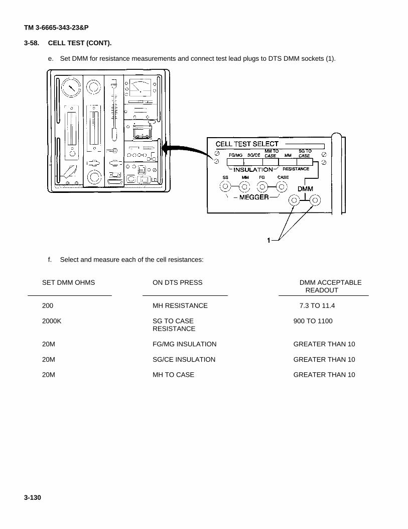
TM 3-6665-343-23&P
3-58. CELL TEST (CONT).
e. Set DMM for resistance measurements and connect test lead plugs to DTS DMM sockets (1).
f. Select and measure each of the cell resistances:
SET DMM OHMS
200
2000K
20M
20M
20M
ON DTS PRESS
MH RESISTANCE
SG TO CASERESISTANCE
FG/MG INSULATION
SG/CE INSULATION
MH TO CASE
DMM ACCEPTABLEREADOUT
7.3 TO 11.4
900 TO 1100
GREATER THAN 10
GREATER THAN 10
GREATER THAN 10
3-130
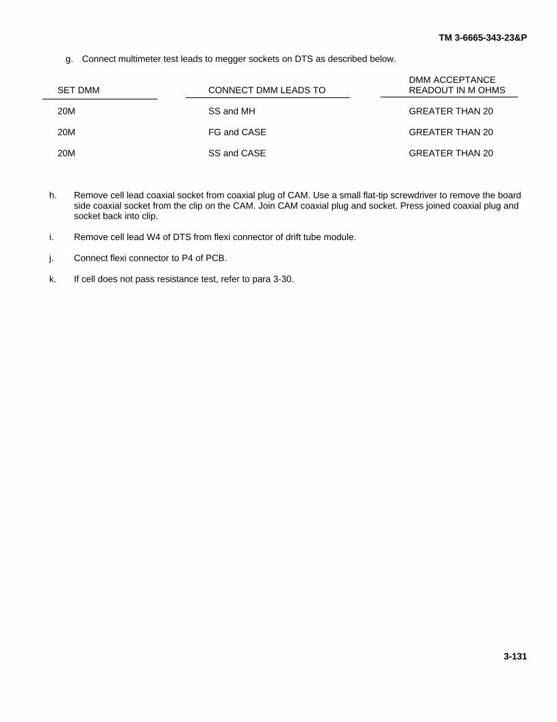
TM 3-6665-343-23&P
g. Connect multimeter test leads to megger sockets on DTS as described below.
SET DMM
20M
20M
20M
CONNECT DMM LEADS TO
SS and MH
FG and CASE
SS and CASE
DMM ACCEPTANCEREADOUT IN M OHMS
GREATER THAN 20
GREATER THAN 20
GREATER THAN 20
h. Remove cell lead coaxial socket from coaxial plug of CAM. Use a small flat-tip screwdriver to remove the boardside coaxial socket from the clip on the CAM. Join CAM coaxial plug and socket. Press joined coaxial plug andsocket back into clip.
i. Remove cell lead W4 of DTS from flexi connector of drift tube module.
j. Connect flexi connector to P4 of PCB.
k. If cell does not pass resistance test, refer to para 3-30.
3-131
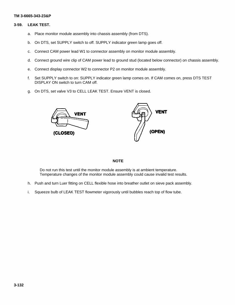
TM 3-6665-343-23&P
3-59. LEAK TEST.
a. Place monitor module assembly into chassis assembly (from DTS).
b. On DTS, set SUPPLY switch to off. SUPPLY indicator green lamp goes off.
c. Connect CAM power lead W1 to connector assembly on monitor module assembly.
d. Connect ground wire clip of CAM power lead to ground stud (located below connector) on chassis assembly.
e. Connect display connector W2 to connector P2 on monitor module assembly.
f. Set SUPPLY switch to on: SUPPLY indicator green lamp comes on. If CAM comes on, press DTS TESTDISPLAY ON switch to turn CAM off.
g. On DTS, set valve V3 to CELL LEAK TEST. Ensure VENT is closed.
NOTE
Do not run this test until the monitor module assembly is at ambient temperature.Temperature changes of the monitor module assembly could cause invalid test results.
h. Push and turn Luer fitting on CELL flexible hose into breather outlet on sieve pack assembly.
i. Squeeze bulb of LEAK TEST flowmeter vigorously until bubbles reach top of flow tube.
3-132
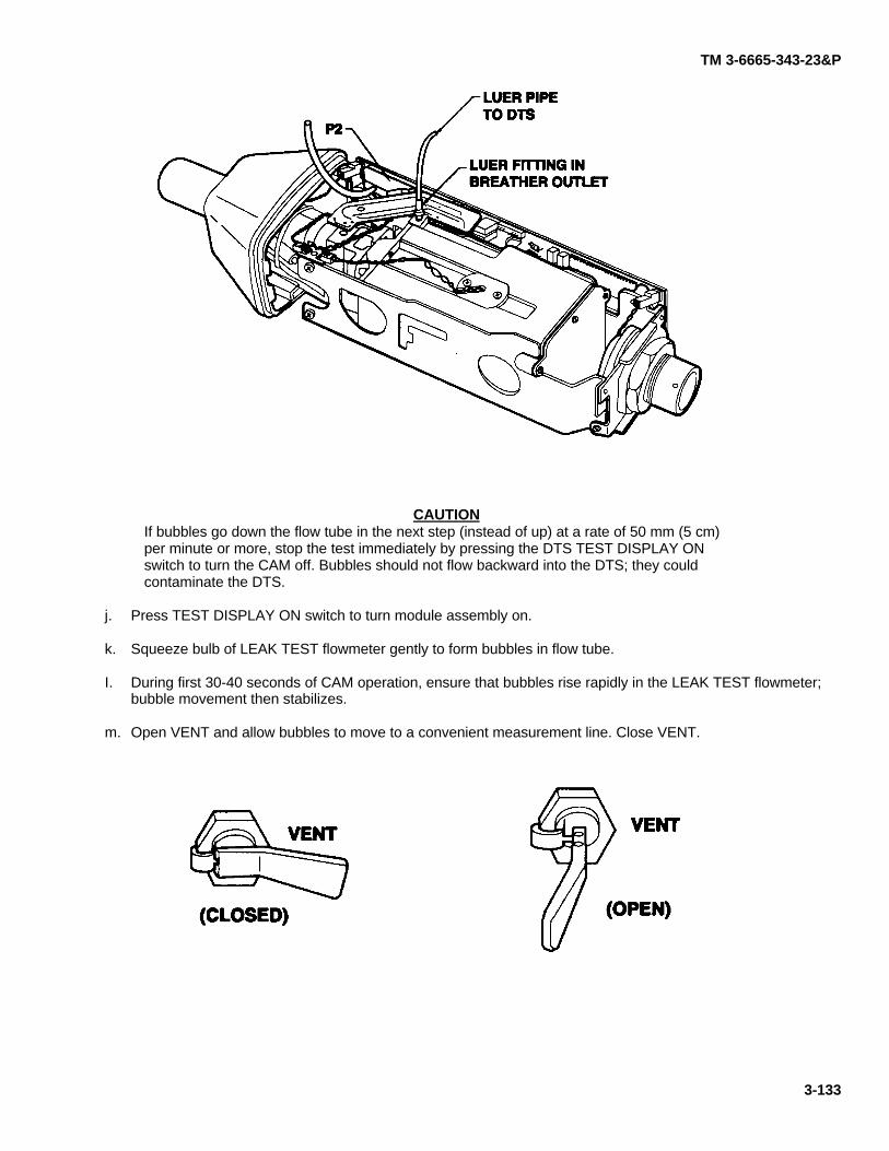
TM 3-6665-343-23&P
CAUTIONIf bubbles go down the flow tube in the next step (instead of up) at a rate of 50 mm (5 cm)per minute or more, stop the test immediately by pressing the DTS TEST DISPLAY ONswitch to turn the CAM off. Bubbles should not flow backward into the DTS; they couldcontaminate the DTS.
j. Press TEST DISPLAY ON switch to turn module assembly on.
k. Squeeze bulb of LEAK TEST flowmeter gently to form bubbles in flow tube.
I. During first 30-40 seconds of CAM operation, ensure that bubbles rise rapidly in the LEAK TEST flowmeter;bubble movement then stabilizes.
m. Open VENT and allow bubbles to move to a convenient measurement line. Close VENT.
3-133
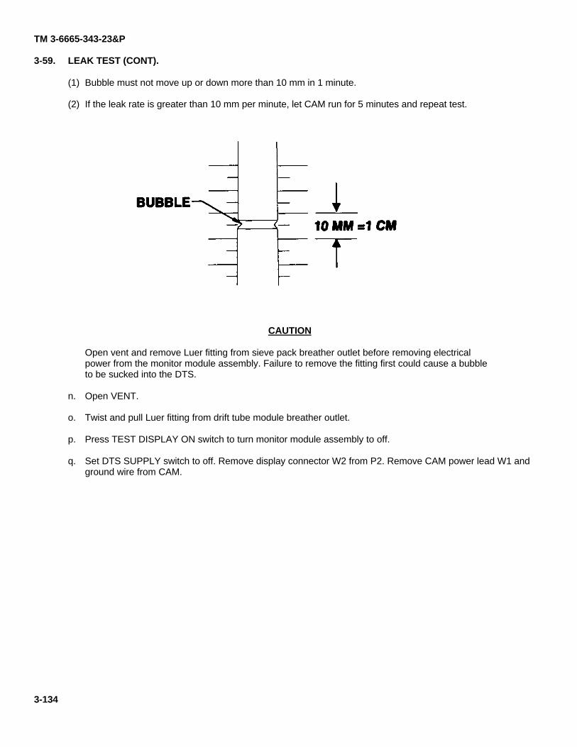
TM 3-6665-343-23&P
3-59. LEAK TEST (CONT).
(1) Bubble must not move up or down more than 10 mm in 1 minute.
(2) If the leak rate is greater than 10 mm per minute, let CAM run for 5 minutes and repeat test.
CAUTION
Open vent and remove Luer fitting from sieve pack breather outlet before removing electricalpower from the monitor module assembly. Failure to remove the fitting first could cause a bubbleto be sucked into the DTS.
n. Open VENT.
o. Twist and pull Luer fitting from drift tube module breather outlet.
p. Press TEST DISPLAY ON switch to turn monitor module assembly to off.
q. Set DTS SUPPLY switch to off. Remove display connector W2 from P2. Remove CAM power lead W1 andground wire from CAM.
3-134
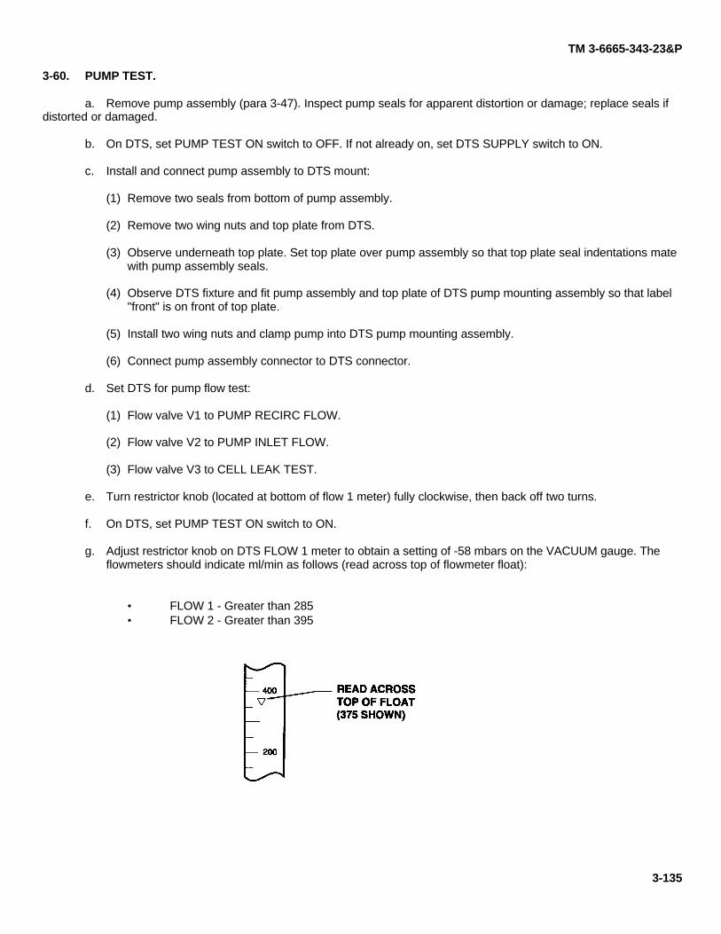
TM 3-6665-343-23&P
3-60. PUMP TEST.
a. Remove pump assembly (para 3-47). Inspect pump seals for apparent distortion or damage; replace seals ifdistorted or damaged.
b. On DTS, set PUMP TEST ON switch to OFF. If not already on, set DTS SUPPLY switch to ON.
c. Install and connect pump assembly to DTS mount:
(1) Remove two seals from bottom of pump assembly.
(2) Remove two wing nuts and top plate from DTS.
(3) Observe underneath top plate. Set top plate over pump assembly so that top plate seal indentations matewith pump assembly seals.
(4) Observe DTS fixture and fit pump assembly and top plate of DTS pump mounting assembly so that label"front" is on front of top plate.
(5) Install two wing nuts and clamp pump into DTS pump mounting assembly.
(6) Connect pump assembly connector to DTS connector.
d. Set DTS for pump flow test:
(1) Flow valve V1 to PUMP RECIRC FLOW.
(2) Flow valve V2 to PUMP INLET FLOW.
(3) Flow valve V3 to CELL LEAK TEST.
e. Turn restrictor knob (located at bottom of flow 1 meter) fully clockwise, then back off two turns.
f. On DTS, set PUMP TEST ON switch to ON.
g. Adjust restrictor knob on DTS FLOW 1 meter to obtain a setting of -58 mbars on the VACUUM gauge. Theflowmeters should indicate ml/min as follows (read across top of flowmeter float):
• FLOW 1 - Greater than 285• FLOW 2 - Greater than 395
3-135
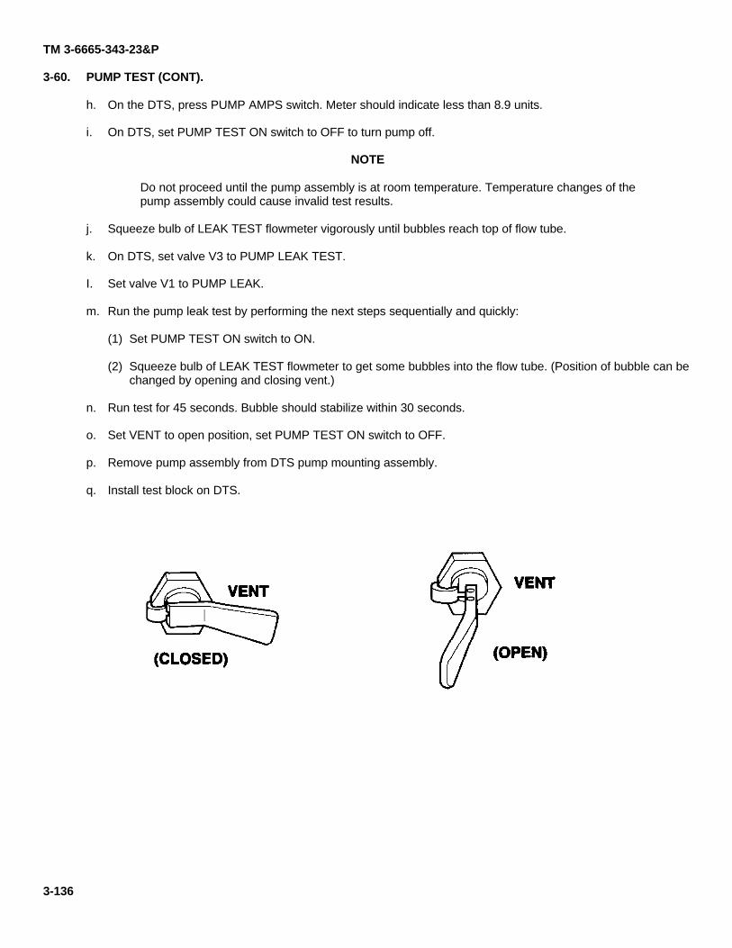
TM 3-6665-343-23&P
3-60. PUMP TEST (CONT).
h. On the DTS, press PUMP AMPS switch. Meter should indicate less than 8.9 units.
i. On DTS, set PUMP TEST ON switch to OFF to turn pump off.
NOTE
Do not proceed until the pump assembly is at room temperature. Temperature changes of thepump assembly could cause invalid test results.
j. Squeeze bulb of LEAK TEST flowmeter vigorously until bubbles reach top of flow tube.
k. On DTS, set valve V3 to PUMP LEAK TEST.
I. Set valve V1 to PUMP LEAK.
m. Run the pump leak test by performing the next steps sequentially and quickly:
(1) Set PUMP TEST ON switch to ON.
(2) Squeeze bulb of LEAK TEST flowmeter to get some bubbles into the flow tube. (Position of bubble can bechanged by opening and closing vent.)
n. Run test for 45 seconds. Bubble should stabilize within 30 seconds.
o. Set VENT to open position, set PUMP TEST ON switch to OFF.
p. Remove pump assembly from DTS pump mounting assembly.
q. Install test block on DTS.
3-136
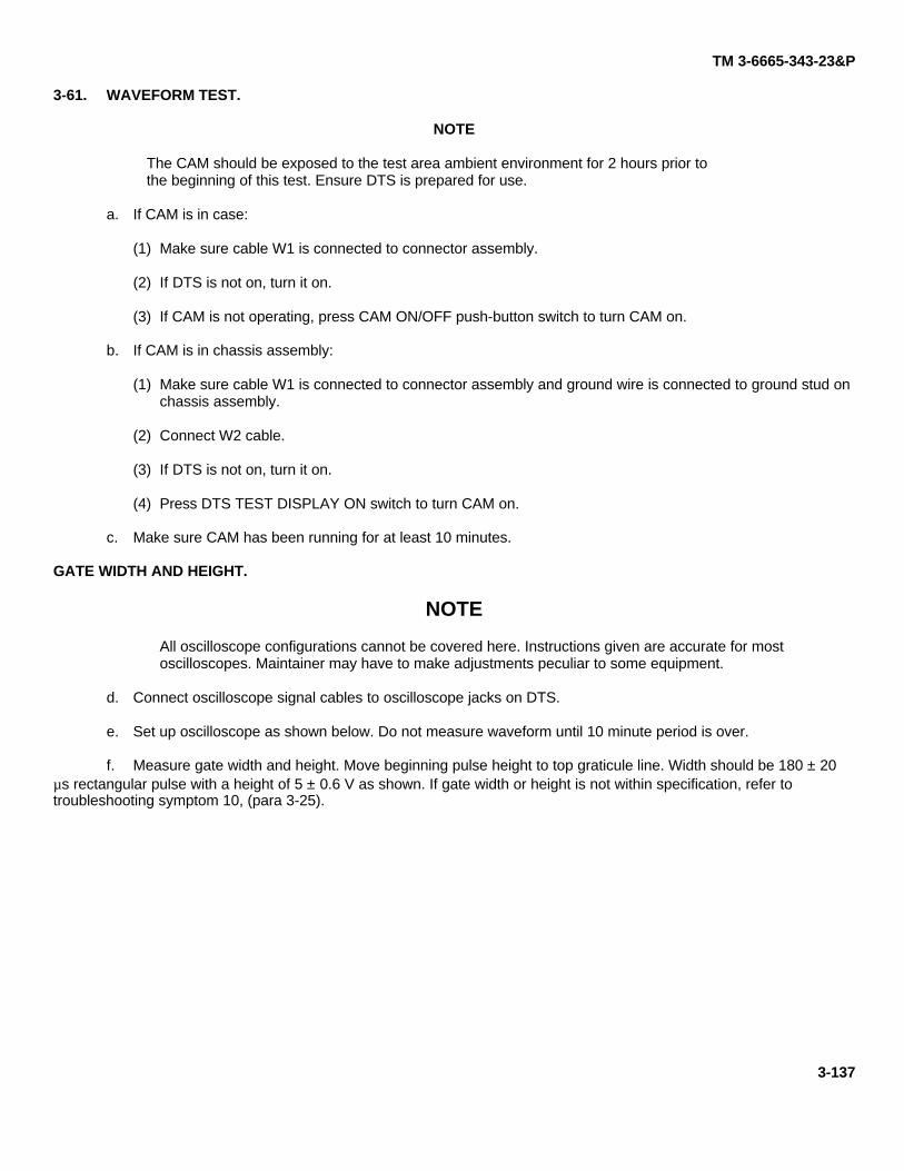
TM 3-6665-343-23&P
3-61. WAVEFORM TEST.
NOTE
The CAM should be exposed to the test area ambient environment for 2 hours prior tothe beginning of this test. Ensure DTS is prepared for use.
a. If CAM is in case:
(1) Make sure cable W1 is connected to connector assembly.
(2) If DTS is not on, turn it on.
(3) If CAM is not operating, press CAM ON/OFF push-button switch to turn CAM on.
b. If CAM is in chassis assembly:
(1) Make sure cable W1 is connected to connector assembly and ground wire is connected to ground stud onchassis assembly.
(2) Connect W2 cable.
(3) If DTS is not on, turn it on.
(4) Press DTS TEST DISPLAY ON switch to turn CAM on.
c. Make sure CAM has been running for at least 10 minutes.
GATE WIDTH AND HEIGHT.
NOTE
All oscilloscope configurations cannot be covered here. Instructions given are accurate for mostoscilloscopes. Maintainer may have to make adjustments peculiar to some equipment.
d. Connect oscilloscope signal cables to oscilloscope jacks on DTS.
e. Set up oscilloscope as shown below. Do not measure waveform until 10 minute period is over.
f. Measure gate width and height. Move beginning pulse height to top graticule line. Width should be 180 ± 20µs rectangular pulse with a height of 5 ± 0.6 V as shown. If gate width or height is not within specification, refer totroubleshooting symptom 10, (para 3-25).
3-137
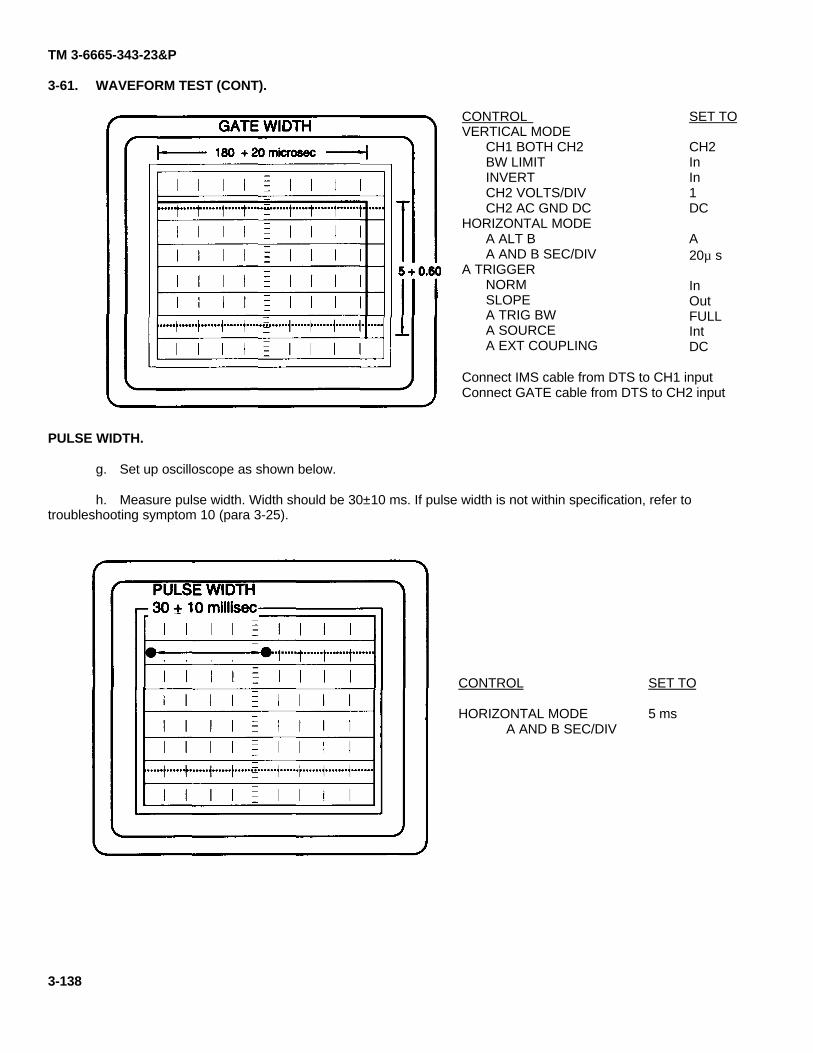
TM 3-6665-343-23&P
3-61. WAVEFORM TEST (CONT).
CONTROL VERTICAL MODE
CH1 BOTH CH2BW LIMITINVERTCH2 VOLTS/DIVCH2 AC GND DC
HORIZONTAL MODEA ALT BA AND B SEC/DIV
A TRIGGERNORMSLOPEA TRIG BWA SOURCEA EXT COUPLING
SET TO
CH2InIn1DC
A20µ s
InOutFULLIntDC
Connect IMS cable from DTS to CH1 inputConnect GATE cable from DTS to CH2 input
PULSE WIDTH.
g. Set up oscilloscope as shown below.
h. Measure pulse width. Width should be 30±10 ms. If pulse width is not within specification, refer totroubleshooting symptom 10 (para 3-25).
CONTROL
HORIZONTAL MODEA AND B SEC/DIV
SET TO
5 ms
3-138
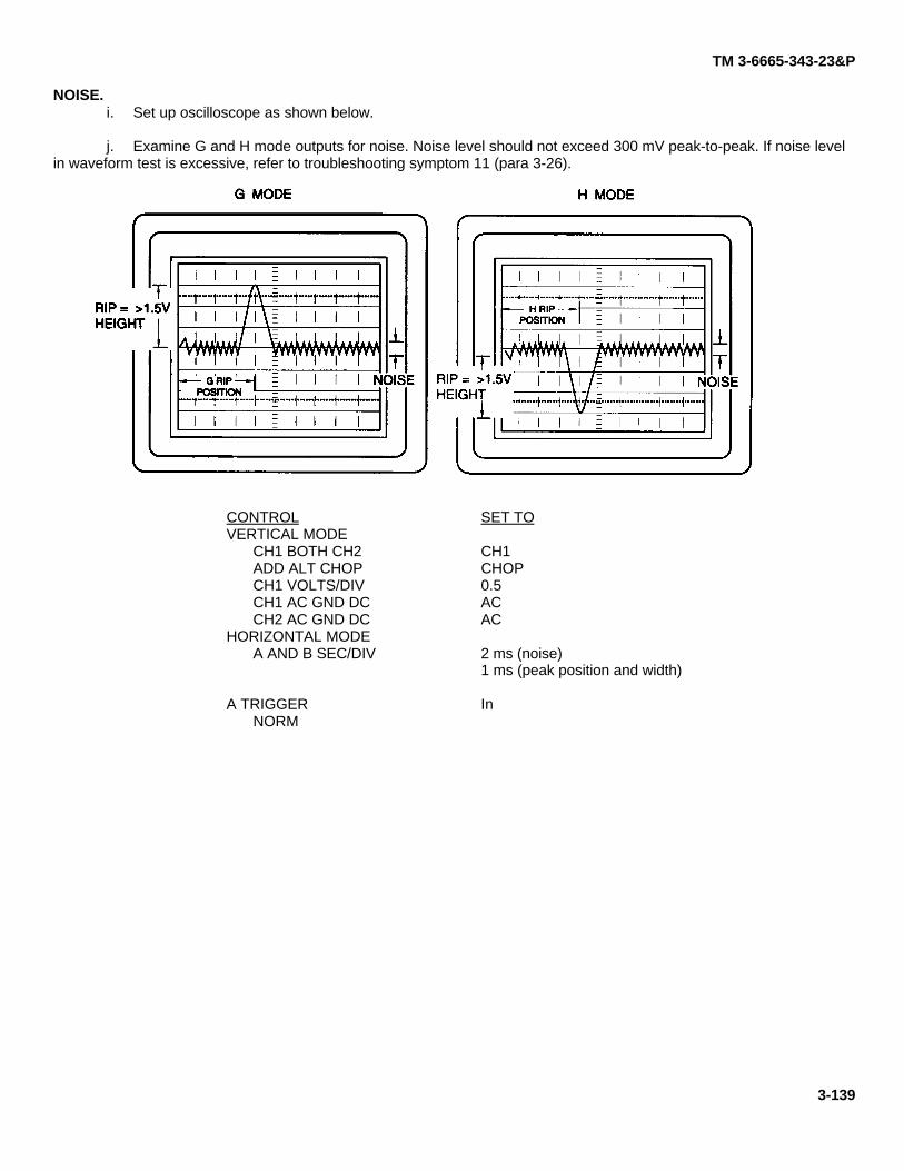
TM 3-6665-343-23&P
NOISE.i. Set up oscilloscope as shown below.
j. Examine G and H mode outputs for noise. Noise level should not exceed 300 mV peak-to-peak. If noise levelin waveform test is excessive, refer to troubleshooting symptom 11 (para 3-26).
CONTROLVERTICAL MODE
CH1 BOTH CH2ADD ALT CHOPCH1 VOLTS/DIVCH1 AC GND DCCH2 AC GND DC
HORIZONTAL MODEA AND B SEC/DIV
A TRIGGERNORM
SET TO
CH1CHOP0.5ACAC
2 ms (noise)1 ms (peak position and width)
In
3-139
TM 3-6665-343-23&P
3-61. WAVEFORM TEST (CONT).
SECONDARY PEAKS.
NOTE
Secondary peaks are any visible peak other than the normal RIP. They may lookmuch like the peaks that show when a CAM is exposed to simulant, but do notdiminish and disappear within a few minutes. A secondary peak due tocontamination can occur anywhere on the waveform, depending on the source ofthe contamination. However, do not consider a peak that occurs within 1 ms fromthe center of the RIP to be a secondary peak. A corresponding bar reading onthe CAM may or may not be present. To become familiar with the types of peakscontamination causes, observe the response of a good CAM to simulant.
k. Set CH1 VOLTS/DIV to 1. Set A and B SEC/DIV to 2 ms. Observe for secondary peaks occurring after the mainpeak in both the G and H modes. There should not be any secondary peaks. Secondary peaks indicate the presence ofcontamination (see below). If secondary peaks are present in waveform test, remove nozzle protective cap. If secondarypeaks significantly decrease in amplitude, clean nozzle assembly area with a dampened cheesecloth and install a newprotective cap. If secondary peaks are still present in waveform test, refer to troubleshooting symptom 12 (para 3-27).
I. Set CH1 to DC and measure dc offset from zero in both the G and H modes: offset should be less than 1 V dc. IfDC offset is greater than 1 V dc, refer to troubleshooting symptom 13, para 3-28.
NOTE
Wait a few seconds after switching modes to make peak measurements.
m. Set CH1 to AC. Set A and B SEC/DIV on oscilloscope to 1 ms. Make the following reactant ion peak (RIP)measurements:
(1) H mode peak height: greater than 1.5 V peak.
(2) G mode peak height: greater than 1.5 V peak.
n. If (G or H) peak heights are not within specifications, refer to troubleshooting symptom 14 (para 3-29).
3-140
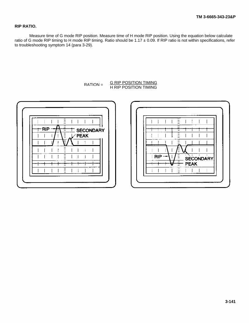
TM 3-6665-343-23&P
RIP RATIO.
Measure time of G mode RIP position. Measure time of H mode RIP position. Using the equation below calculateratio of G mode RIP timing to H mode RIP timing. Ratio should be 1.17 ± 0.09. If RIP ratio is not within specifications, referto troubleshooting symptom 14 (para 3-29).
G RIP POSITION TIMINGH RIP POSITION TIMING
3-141
RATION =
TM 3-6665-343-23&P
Section V. PREPARATION FOR STORAGE OR SHIPMENT
3-62. STORAGE.
a. Store CAM in a secure area when unattended.
b. Post the area with CAUTION - RADIOACTIVE MATERIAL signs as required.
c. The signs shall be yellow with magenta letters and radiation symbol at least 8 inches by 10 inches. Post signson outside of lockable containers.
d. Storage of a single CAM must be in a secure area; the area does not need to be marked.
3-63. SHIPMENT.
Refer to AR 385-11 for receiving, unloading, and movement of radioactive materials.
a. Packing.
(1) Pack the CAM in the original shipping pack and over pack with a cardboard box or wooden box.
CAUTION
Cushioning and overpacking should be chemically clean so that no outgassing occurs. If possibleinclude desiccant and double wrap the CAM with vapor barrier and polyethylene bag.
(2) If the original shipping pack is not available, use available cushioning and over pack with a cardboard orwooden box.
(3) The Government Bill of Lading or other shipping document should be completed in accordance with 49Code of Federal Regulations, and Army and local regulations.
b. Instructions for shipment of any CAM marked XXX will be provided by the point of contact below:
Armament and Chemical Acquisition and Logistics ActivityATTN: AMSTA-AC-CTC-DRock Island, IL 61299-7630DSN 793-5961COM (309) 782-5961
3-64. ACCOUNTABILITY.
Accountability will be maintained at the Property Book level. For instructions on completing transactions contactyour Cell Serialization Surety Office (CSSO) in accordance with AR 710-3, Chapter 4, Section 2 for radiation trackingrequirements. A transaction is required for each of the following:
a. Inventory lossb. Suspected loss or theftc. Receiptd. Shipmente. Demilitarizationf. Wipe test resultg. Removal of drift tube module from CAM.
3-142
TM 3-6665-343-23&P
APPENDIX AREFERENCES
A-1. SCOPE.
This appendix lists service publications referenced in this manual.
A-2. ARMY REGULATIONS.
AR 55-38 ...................................................................
AR 385-11 .................................................................
AR 385-40 .................................................................
AR 700-64 .................................................................
AR 710-3 ...................................................................
AR 735-11-2 ..............................................................
Reporting of Transportation Discrepancies in Shipments
Ionizing Radiation Protection (Licensing, Control,Transportation, disposal, and Radiation Safety)
Accident Reporting and Records
Radioactive Commodities in the DoD Supply Systems
Asset and Transaction Reporting System
Reporting of Item and Packaging Discrepancies
A-3. COMMON TABLE OF ALLOWANCES.
CTA 50-970 ...............................................................
CTA 8-100.................................................................
Expendable and Durable Items (Except: Medical ClassV, Repair Parts and Heraldic Items)Army Medical Department Expendable and DurableItems
A-4. DA PAMPHLETS.
DA PAM 738-750....................................................... Functional Users Manual for The Army MaintenanceManagement System(TAMMS)
A-5. FIELD MANUALS.
FM 3-5.......................................................................FM 21-11...................................................................
NBC DecontaminationFirst Aid for Soldiers
A-6. FORMS.
DA Form 2028-2 ........................................................
RCS DD-SD(AR) 1168...............................................SF 361 ......................................................................SF 364 ......................................................................SF 368 ......................................................................
Recommended Changes to Equipment TechnicalPublicationsRadiological Accident ReportTransportation Discrepancy ReportReport of DiscrepancyProduct Quality Deficiency Report
A-1
TM 3-6665-343-23&P
A-7. SOLDIER TRAINING PUBLICATIONS.
STP 21-1-5MCT ........................................................ Soldier's Manual of Common Tasks, Skill Level 1
A-8. TECHNICAL MANUALS.
TM 3-6665-343-10 .....................................................
TM 3-6665-332-13&P ............................................... .
TM 43-0002-31 ..........................................................
TM 750-244-2............................................................
Operator's Manual for Improved Chemical Agent Monitor(CAM)
Operators and Direct Support Maintenance Manual(Including RPSTL) for Diagnostic Test Set (DTS).
Destruction of Chemical Weaponsand Defense Equipment to Prevent Enemy UseProcedure for Destruction of Electronics Materielto Prevent Enemy Use (Electronics Command)
A-9. TECHNICAL BULLETINS.
TB 43-0130................................................................
TB 700-4 ...................................................................
Instructions for the Safe Handling and Identification ofUS Army Communications-Electronics CommandManaged Lithium-Sulfur Dioxide Batteries
Decontamination of Facilities and Equipment
A-2
TM 3-6665-343-23&PAPPENDIX B
MAINTENANCE ALLOCATION CHART (MAC)
Section I. INTRODUCTION
B-1. THE ARMY MAINTENANCE SYSTEM MAC.a. This introduction (Section I) provides a general explanation of all maintenance and repair functions authorized
at various maintenance levels under the standard Army Maintenance System concept.
b. The Maintenance Allocation Chart (MAC) in Section II designates overall authority and responsibility for theperformance of maintenance functions on the identified end item or component. The application of the maintenancefunctions to the end item or component will be consistent with the capacities and capabilities of the designatedmaintenance levels which are shown on the MAC in column (4) as:
Unit - includes two subcolumns, C (operator/crew) and O (unit) maintenance.Direct Support - includes an F subcolumn.General Support - includes an H subcolumn.Depot - includes a D subcolumn.
c. Section III lists the tools and test equipment (both special tools and common tool sets) required for eachmaintenance function as referenced from Section II.
d. Section IV contains supplemental instructions and explanatory notes for a particular maintenance function.
B-2. MAINTENANCE FUNCTIONS.
Maintenance functions will be limited to and defined as follows:
a. Inspect. To determine the serviceability of an item by comparing its physical, mechanical, and/or electricalcharacteristics with established standards through examination (e.g., by sight, sound, or feel).
b. Test. To verify serviceability by measuring the mechanical, pneumatic, hydraulic, or electrical characteristicsof an item and comparing those characteristics with prescribed standards.
c. Service. Operations required periodically to keep an item in proper operating condition; i.e., to clean (includesdecontaminate, when required), to preserve, to drain, to paint, or to replenish fuel, lubricants, chemical fluids or gases.
d. Adjust. To maintain or regulate, within prescribed limits, by bringing into proper or exact position, or by settingthe operating characteristics to specified parameters.
e. Align. To adjust specified variable elements of an item to bring about optimum or desired performance.
f. Calibrate. To determine and cause corrections to be made or to be adjusted on instruments or test,measuring, and diagnostic equipments used in precision measurement. Consists of comparisons of two instruments, oneof which is a certified standard of known accuracy, to detect and adjust any discrepancy in the accuracy of the instrumentbeing compared.
B-1
TM 3-6665-343-23&P
B-2. MAINTENANCE FUNCTIONS (CONT).
g. Remove/Install. To remove and install the same item when required to perform service or other maintenancefunctions. Install may be the act of emplacing, seating, or fixing into position a spare, repair part, or module (component orassembly) in a manner to allow the proper functioning of an equipment or system.
h. Replace. To remove an unserviceable item and install a serviceable counterpart in its place. "Replace" isauthorized by the MAC and assigned maintenance level is shown as the 3rd position code of the SMR code.
i. Repair. The application of maintenance services including fault location/troubleshooting, removal/installation,and disassembly/assembly procedures, and maintenance actions to identify troubles and restore serviceability to an itemby correcting specific damage, fault, malfunction, or failure in a part, subassembly, module (component or assembly), enditem, or system.
j. Overhaul. That maintenance effort (service/action) prescribed to restore an item to a completelyserviceable/operational condition as required by maintenance standards in appropriate technical publications (i.e. DMWR).Overhaul is normally the highest degree of maintenance performed by the Army. Overhaul does not normally return anitem to like new condition.
k. Rebuild. Consists of those services/actions necessary for the restoration of unserviceable equipment to a likenew condition in accordance with original manufacturing standards. Rebuild is the highest degree of materiel maintenanceapplied to Army equipment. The rebuild operation includes the act of returning to zero those age measurements (hours,miles, etc.) considered in classifying Army equipment/components.
B-3. EXPLANATION OF COLUMNS IN THE MAC, SECTION II.
a. Column (1), Group Number. Column (1) lists functional group code numbers, the purpose of which is toidentify maintenance significant components, assemblies, subassemblies, and modules with the next higher assembly.
b. Column (2), Component/Assembly. Column (2) contains the item names of components, assemblies,subassemblies, and modules for which maintenance is authorized.
c. Column (3), Maintenance Function. Column (3) lists the functions to be performed on the item listed incolumn (2).
d. Column (4), Maintenance Level. Column (4) specifies, by the listing of a work time figure in the appropriatesubcolumn(s), the level of maintenance authorized to perform the function listed in column (3). This figure represents theactive time required to perform that maintenance function at the indicated level of maintenance. If the number orcomplexity of the tasks within the listed maintenance function vary at different levels, appropriate work time figures will beshown for each level. The work time figure represents the average time required to restore an item (assembly,subassembly, component, module, end item, or system) to a serviceable condition under typical field operating conditions.This time includes preparation time (including any necessary disassembly/assembly time), troubleshooting/fault locationtime, and quality assurance/quality control time in addition to the time required to perform the specific tasks identified forthe maintenance functions authorized in the Maintenance Allocation Chart.
The symbol designations for the various maintenance levels are as follows:
C ----------------------O ----------------------F-----------------------H ----------------------L-----------------------D ----------------------
Operator or CrewUnit MaintenanceDirect Support MaintenanceGeneral Support MaintenanceSpecialized Repair Activity (SRA)Depot Maintenance
B-2
TM 3-6665-343-23&P
e. Column (5), Tools and Equipment. Column (5) specifies, by code, those common tool sets (not individualtools), and special tools, TMDE, and support equipment required to perform the designated function.
f. Column (6), Remarks. This column shall, when applicable, contain a letter code, in alphabetic order, whichshall be keyed to the remarks contained in Section IV.
B-4. EXPLANATION OF COLUMNS IN TOOL AND TEST EQUIPMENT REQUIREMENTS, SECTION III.
a. Column (1), Reference Code. The tool and test equipment reference code correlates with the code used inthe MAC, Section II, Column 5.
b. Column (2), Maintenance Level. The lowest level of maintenance authorized to use the tool or testequipment.
c. Column (3), Nomenclature. Name or identification of the tool or test equipment.
d. Column (4), National Stock Number. The National stock number of the tool or test equipment.
e. Column (5), Tool Number. The manufacturer's part number.
B-5. EXPLANATION OF COLUMNS IN REMARKS, SECTION IV.
a. Column (1), Reference Code. The code recorded in column 6, Section II.
b. Column (2), Remarks. This column lists information pertinent to the maintenance function being performed asindicated in the MAC, Section II.
B-3
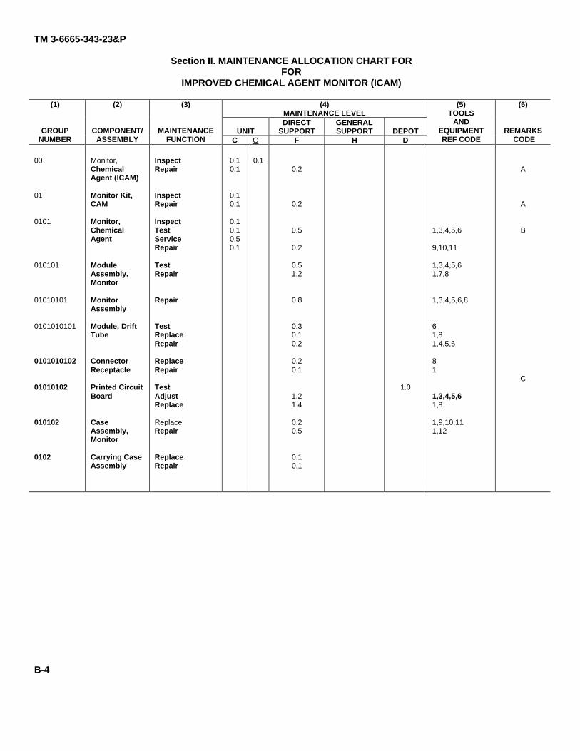
TM 3-6665-343-23&P
Section II. MAINTENANCE ALLOCATION CHART FORFOR
IMPROVED CHEMICAL AGENT MONITOR (ICAM)
(4)MAINTENANCE LEVEL
UNITDIRECT
SUPPORTGENERALSUPPORT DEPOT
(1)
GROUPNUMBER
(2)
COMPONENT/ASSEMBLY
(3)
MAINTENANCEFUNCTION C O F H D
(5)TOOLS
ANDEQUIPMENTREF CODE
(6)
REMARKS CODE
00
01
0101
010101
01010101
0101010101
0101010102
01010102
010102
0102
Monitor,ChemicalAgent (ICAM)
Monitor Kit,CAM
Monitor,ChemicalAgent
ModuleAssembly,Monitor
MonitorAssembly
Module, DriftTube
ConnectorReceptacle
Printed CircuitBoard
CaseAssembly,Monitor
Carrying CaseAssembly
InspectRepair
InspectRepair
InspectTestServiceRepair
TestRepair
Repair
TestReplaceRepair
ReplaceRepair
TestAdjustReplace
ReplaceRepair
ReplaceRepair
0.10.1
0.10.1
0.10.10.50.1
0.10.2
0.2
0.5
0.2
0.51.2
0.8
0.30.10.2
0.20.1
1.21.4
0.20.5
0.10.1
1.0
1,3,4,5,6
9,10,11
1,3,4,5,61,7,8
1,3,4,5,6,8
61,81,4,5,6
81
1,3,4,5,61,8
1,9,10,111,12
A
A
B
C
B-4
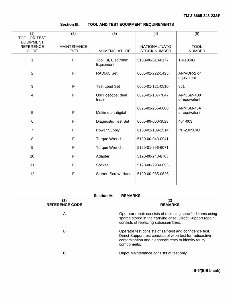
TM 3-6665-343-23&P
Section III. TOOL AND TEST EQUIPMENT REQUIREMENTS
(1)TOOL OR TEST
EQUIPMENTREFERENCE
CODE
(2)
MAINTENANCELEVEL
(3)
NOMENCLATURE
(4)
NATIONAL/NATOSTOCK NUMBER
(5)
TOOLNUMBER
1
2
3
4
5
6
7
8
9
10
11
12
F
F
F
F
F
F
F
F
F
F
F
F
Tool Kit, ElectronicEquipment
RADIAC Set
Test Lead Set
Oscilloscope, dualtrace
Multimeter, digital
Diagnostic Test Set
Power Supply
Torque Wrench
Torque Wrench
Adapter
Socket
Starter, Screw, Hand
5180-00-610-8177
6665-01-222-1425
6665-01-121-0510
6625-01-187-7847
6625-01-265-6000
6665-99-000-3023
6130-01-139-2514
5120-00-943-0941
5120-01-396-6071
5120-00-240-8703
5120-00-293-0093
5120-00-965-0626
TK-105/G
AN/VDR-2 orequivalent
861
AN/USM-488or equivalent
AN/PSM-45Aor equivalent
464-003
PP-2309C/U
Section IV. REMARKS(1)
REFERENCE CODE(2)
REMARKS
A Operator repair consists of replacing specified items usingspares stored in the carrying case. Direct Support repairconsists of replacing subassemblies.
B Operator test consists of self-test and confidence test.Direct Support test consists of wipe test for radioactivecontamination and diagnostic tests to identify faultycomponents.
C Depot Maintenance consists of test only.
B-5/(B-6 blank)
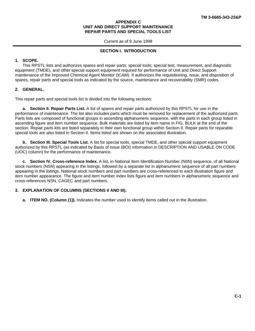
TM 3-6665-343-23&PAPPENDIX C
UNIT AND DIRECT SUPPORT MAINTENANCEREPAIR PARTS AND SPECIAL TOOLS LIST
Current as of 9 June 1998
SECTION I. INTRODUCTION
1. SCOPE.This RPSTL lists and authorizes spares and repair parts; special tools; special test, measurement, and diagnostic
equipment (TMDE), and other special support equipment required for performance of Unit and Direct Supportmaintenance of the Improved Chemical Agent Monitor (ICAM). It authorizes the requisitioning, issue, and disposition ofspares, repair parts and special tools as indicated by the source, maintenance and recoverability (SMR) codes.
2. GENERAL.
This repair parts and special tools list is divided into the following sections:
a. Section II. Repair Parts List. A list of spares and repair parts authorized by this RPSTL for use in theperformance of maintenance. The list also includes parts which must be removed for replacement of the authorized parts.Parts lists are composed of functional groups in ascending alphanumeric sequence, with the parts in each group listed inascending figure and item number sequence. Bulk materials are listed by item name in FIG. BULK at the end of thesection. Repair parts kits are listed separately in their own functional group within Section II. Repair parts for reparablespecial tools are also listed in Section II. Items listed are shown on the associated illustration.
b. Section III. Special Tools List. A list for special tools, special TMDE, and other special support equipmentauthorized by this RPSTL (as indicated by Basis of Issue (BOI) information in DESCRIPTION AND USABLE ON CODE(UOC) column) for the performance of maintenance.
c. Section IV. Cross-reference Index. A list, in National Item Identification Number (NIIN) sequence, of all Nationalstock numbers (NSN) appearing in the listings, followed by a separate list in alphanumeric sequence of all part numbersappearing in the listings. National stock numbers and part numbers are cross-referenced to each illustration figure anditem number appearance. The figure and item number index lists figure and item numbers in alphanumeric sequence andcross-references NSN, CAGEC and part numbers.
3. EXPLANATION OF COLUMNS (SECTIONS II AND III).
a. ITEM NO. (Column (1)). Indicates the number used to identify items called out in the illustration.
C-1
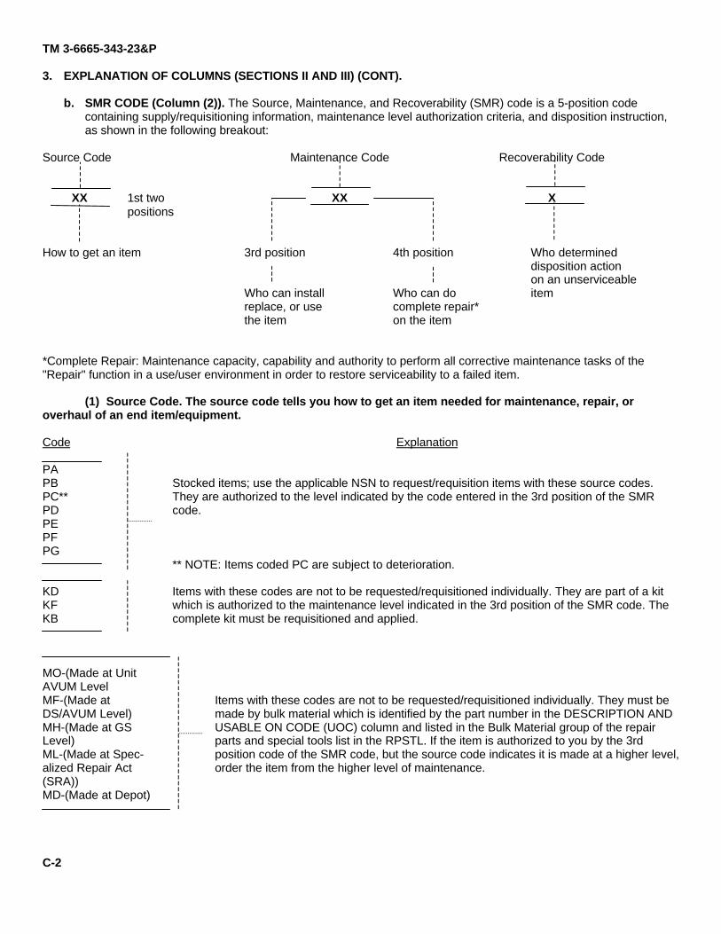
TM 3-6665-343-23&P
3. EXPLANATION OF COLUMNS (SECTIONS II AND III) (CONT).
b. SMR CODE (Column (2)). The Source, Maintenance, and Recoverability (SMR) code is a 5-position codecontaining supply/requisitioning information, maintenance level authorization criteria, and disposition instruction,as shown in the following breakout:
Source Code Maintenance Code Recoverability Code
XX 1st two XX Xpositions
How to get an item 3rd position 4th position Who determineddisposition actionon an unserviceable
Who can install Who can do itemreplace, or use complete repair*the item on the item
*Complete Repair: Maintenance capacity, capability and authority to perform all corrective maintenance tasks of the"Repair" function in a use/user environment in order to restore serviceability to a failed item.
(1) Source Code. The source code tells you how to get an item needed for maintenance, repair, oroverhaul of an end item/equipment.
Code
PAPBPC**PDPEPFPG
KDKFKB
MO-(Made at UnitAVUM LevelMF-(Made atDS/AVUM Level)MH-(Made at GSLevel)ML-(Made at Spec-alized Repair Act(SRA))MD-(Made at Depot)
Explanation
Stocked items; use the applicable NSN to request/requisition items with these source codes.They are authorized to the level indicated by the code entered in the 3rd position of the SMRcode.
** NOTE: Items coded PC are subject to deterioration.
Items with these codes are not to be requested/requisitioned individually. They are part of a kitwhich is authorized to the maintenance level indicated in the 3rd position of the SMR code. Thecomplete kit must be requisitioned and applied.
Items with these codes are not to be requested/requisitioned individually. They must bemade by bulk material which is identified by the part number in the DESCRIPTION ANDUSABLE ON CODE (UOC) column and listed in the Bulk Material group of the repairparts and special tools list in the RPSTL. If the item is authorized to you by the 3rdposition code of the SMR code, but the source code indicates it is made at a higher level,order the item from the higher level of maintenance.
C-2

TM 3-6665-343-23&P
AO-(Assembled atUnit AVUM Level
AF-(Assembled atDS/AVUM Level)
AH-( Assembled at GSLevel)
AL-(Assembled atSpecialized RepairAct (SRA))
AD-(Assembled atDepot)
Items with these codes are not to be requested/requisitioned individually. The parts thatmake up the assembled item must be requisitioned or fabricated and assembled at thelevel of maintenance indicated by the source code. If the 3rd position code of the SMRcode authorizes you to replace the item, but the source code indicates it is assembled ata higher level, order the item from the higher level of maintenance.
XA - Do not requisition an "XA" coded item. Order its next higher assembly. (Also, refer to the NOTE below.)XB - If an "XB" coded item is not available from salvage, order it using the CAGEC and part number given.XC - Installation drawing, diagram, instruction sheet, field service drawing, that is identified by manufacturer's part number.XD - Item is not stocked. Order an "XD" coded item through normal supply channels using the CAGEC and part numbergiven, if no NSN is available.
NOTE: Cannibalization or controlled exchange, when authorized, may be used as a source of supply for itemswith the above source codes, except for those sources coded "XA" or those aircraft support items restricted byrequirements of AR 750-1.
(2) Maintenance Code. Maintenance codes tell you the level(s) of maintenance authorized to USE andREPAIR support items. The maintenance codes are entered in the third and fourth positions of the SMR Code as follows:
(a) The maintenance code entered in the third position tells you the lowest maintenance levelauthorized to remove, replace, and use an item. The maintenance code entered in the third position will indicateauthorization to one of the following levels of maintenance.
Code
C
O
F
H
L
D
Application/Explanation
-Crew or operator maintenance done within Unit or Aviation Unit maintenance.
-Unit or Aviation Unit level can remove, replace, and use the item.
-Direct support or Aviation Intermediate level can remove replace, and use theitem.
-General support level can remove, replace, and use the item.
-Specialized repair activity can remove, replace, and use the item.
-Depot level can remove, replace, and use the item.
(b) The maintenance code entered in the fourth position tells whether or not theitem is to be repaired and identifies the lowest maintenance level with the capability to do complete repair (i.e., perform allauthorized repair functions). (NOTE: Some limited repair may be done on the item at a lower level of maintenance, ifauthorized by the Maintenance Allocation Chart (MAC) and SMR codes.) This position will contain one of the followingmaintenance codes.
C-3
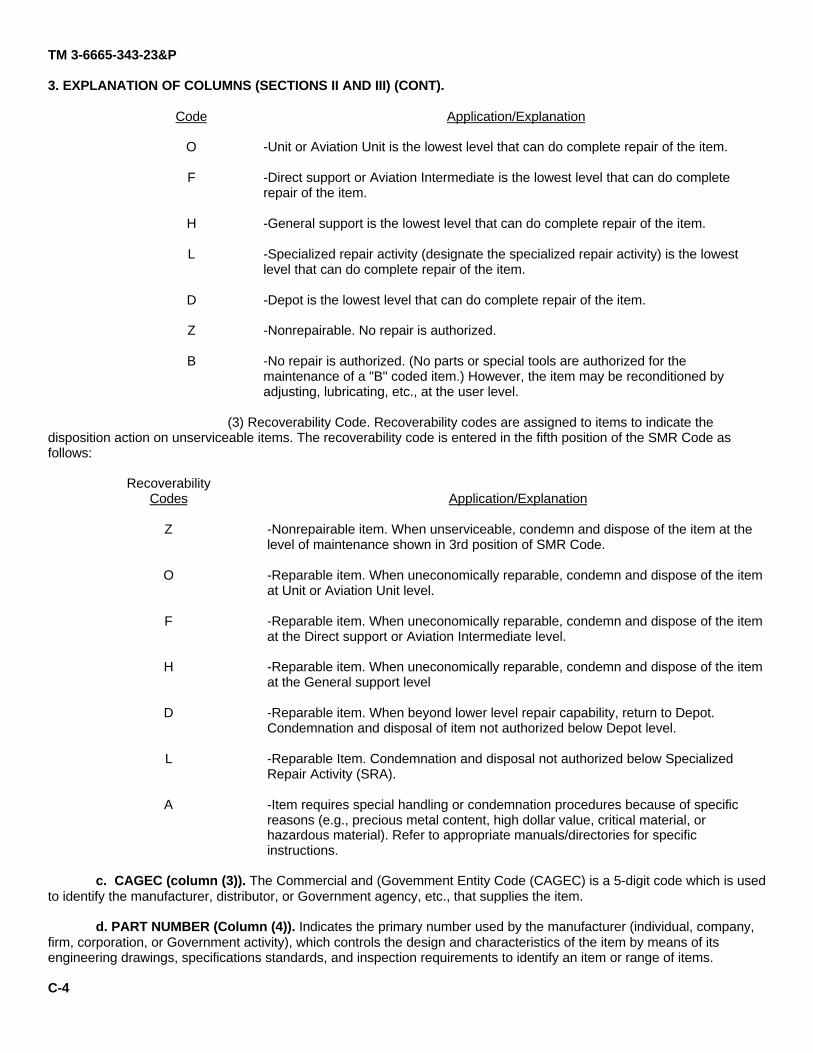
TM 3-6665-343-23&P
3. EXPLANATION OF COLUMNS (SECTIONS II AND III) (CONT).
Code
O
F
H
L
D
Z
B
Application/Explanation
-Unit or Aviation Unit is the lowest level that can do complete repair of the item.
-Direct support or Aviation Intermediate is the lowest level that can do completerepair of the item.
-General support is the lowest level that can do complete repair of the item.
-Specialized repair activity (designate the specialized repair activity) is the lowestlevel that can do complete repair of the item.
-Depot is the lowest level that can do complete repair of the item.
-Nonrepairable. No repair is authorized.
-No repair is authorized. (No parts or special tools are authorized for themaintenance of a "B" coded item.) However, the item may be reconditioned byadjusting, lubricating, etc., at the user level.
(3) Recoverability Code. Recoverability codes are assigned to items to indicate thedisposition action on unserviceable items. The recoverability code is entered in the fifth position of the SMR Code asfollows:
RecoverabilityCodes
Z
O
F
H
D
L
A
Application/Explanation
-Nonrepairable item. When unserviceable, condemn and dispose of the item at thelevel of maintenance shown in 3rd position of SMR Code.
-Reparable item. When uneconomically reparable, condemn and dispose of the itemat Unit or Aviation Unit level.
-Reparable item. When uneconomically reparable, condemn and dispose of the itemat the Direct support or Aviation Intermediate level.
-Reparable item. When uneconomically reparable, condemn and dispose of the itemat the General support level
-Reparable item. When beyond lower level repair capability, return to Depot.Condemnation and disposal of item not authorized below Depot level.
-Reparable Item. Condemnation and disposal not authorized below SpecializedRepair Activity (SRA).
-Item requires special handling or condemnation procedures because of specificreasons (e.g., precious metal content, high dollar value, critical material, orhazardous material). Refer to appropriate manuals/directories for specificinstructions.
c. CAGEC (column (3)). The Commercial and (Govemment Entity Code (CAGEC) is a 5-digit code which is usedto identify the manufacturer, distributor, or Government agency, etc., that supplies the item.
d. PART NUMBER (Column (4)). Indicates the primary number used by the manufacturer (individual, company,firm, corporation, or Government activity), which controls the design and characteristics of the item by means of itsengineering drawings, specifications standards, and inspection requirements to identify an item or range of items.
C-4
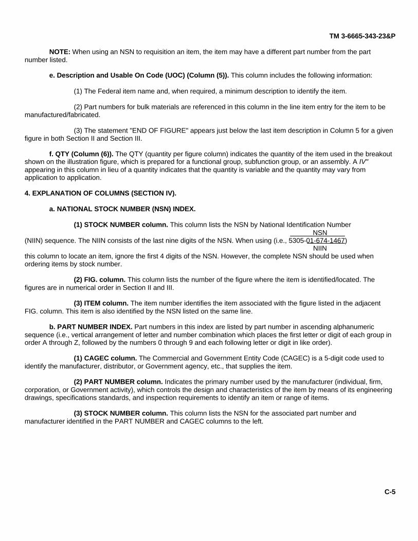
TM 3-6665-343-23&P
NOTE: When using an NSN to requisition an item, the item may have a different part number from the partnumber listed.
e. Description and Usable On Code (UOC) (Column (5)). This column includes the following information:
(1) The Federal item name and, when required, a minimum description to identify the item.
(2) Part numbers for bulk materials are referenced in this column in the line item entry for the item to bemanufactured/fabricated.
(3) The statement "END OF FIGURE" appears just below the last item description in Column 5 for a givenfigure in both Section II and Section III.
f. QTY (Column (6)). The QTY (quantity per figure column) indicates the quantity of the item used in the breakoutshown on the illustration figure, which is prepared for a functional group, subfunction group, or an assembly. A IV"appearing in this column in lieu of a quantity indicates that the quantity is variable and the quantity may vary fromapplication to application.
4. EXPLANATION OF COLUMNS (SECTION IV).
a. NATIONAL STOCK NUMBER (NSN) INDEX.
(1) STOCK NUMBER column. This column lists the NSN by National Identification NumberNSN
(NIIN) sequence. The NIIN consists of the last nine digits of the NSN. When using (i.e., 5305-01-674-1467)NIIN
this column to locate an item, ignore the first 4 digits of the NSN. However, the complete NSN should be used whenordering items by stock number.
(2) FIG. column. This column lists the number of the figure where the item is identified/located. Thefigures are in numerical order in Section II and III.
(3) ITEM column. The item number identifies the item associated with the figure listed in the adjacentFIG. column. This item is also identified by the NSN listed on the same line.
b. PART NUMBER INDEX. Part numbers in this index are listed by part number in ascending alphanumericsequence (i.e., vertical arrangement of letter and number combination which places the first letter or digit of each group inorder A through Z, followed by the numbers 0 through 9 and each following letter or digit in like order).
(1) CAGEC column. The Commercial and Government Entity Code (CAGEC) is a 5-digit code used toidentify the manufacturer, distributor, or Government agency, etc., that supplies the item.
(2) PART NUMBER column. Indicates the primary number used by the manufacturer (individual, firm,corporation, or Government activity), which controls the design and characteristics of the item by means of its engineeringdrawings, specifications standards, and inspection requirements to identify an item or range of items.
(3) STOCK NUMBER column. This column lists the NSN for the associated part number andmanufacturer identified in the PART NUMBER and CAGEC columns to the left.
C-5

TM 3-6665-343-23&P
4. EXPLANATION OF COLUMNS (SECTION IV) (CONT).
(4) FIG. Column. This column lists the number of the figure where the item is identified/located in SectionII and III.
(5) ITEM column. The item number is that number assigned to the item as it appears in the figurereferenced in the adjacent figure number column.
c. FIGURE AND ITEM NUMBER INDEX.
(1) FIG. column. This column lists the number of the figure where the item is identified/located in SectionII and III.
(2) ITEM column. The item number is that number assigned to the item as it appears in the figurereferenced in the adjacent figure number column.
(3) STOCK NUMBER column. This column lists the NSN for the item.
(4) CAGEC column. The Commercial and Government Entity Code (CAGEC) is a 5-digit code used toidentify the manufacturer, distributor, or Government agency, etc., that supplies the item.
(5) PART NUMBER column. Indicates the primary number used by the manufacturer (individual, firm,corporation, or Government activity), which controls the design and characteristics of the item by means of its engineeringdrawings, specification standards, and inspection requirements to identify an item or range of items.
5. SPECIAL INFORMATION.
Not Applicable.
6. HOW TO LOCATE REPAIR PARTS.
a. When National Stock Number or Part Number Is Not Known.
(1) First. Using the table of contents, determine the functional group or subfunctional group to which theitem belongs. This is necessary since figures are prepared for functional groups and subfunctional groups, and listings aredivided into the same groups.
(2) Second. Find the figure covering the functional group or subfunctional group to which the item belongs.
(3) Third. Identify the item on the figure and use the Figure and Item Number Index to find the NSN.
b. When National Stock Number or Part Number is Known.
(1) First. Using the National Stock Number or the part Number Index, find the pertinent National StockNumber or Part Number. The NSN index is in National Item Identification Number (NIIN) sequence (see 4.a). The partnumbers in the Part Number Index are listed in ascending alphanumeric sequence (see 4.b). Both indexes cross-referenceyou to the illustration/figure and item number of the item you are looking for.
(2) Second. Turn to the figure and item number, verify that the item is the one you are looking for, thenlocate the item number in the repair parts list for the figure.
C-6 /(C-7 blank)
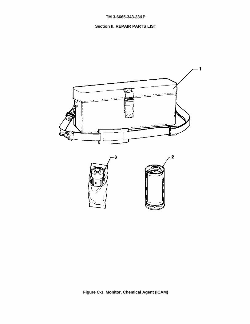
TM 3-6665-343-23&P
Section II. REPAIR PARTS LIST
Figure C-1. Monitor, Chemical Agent (ICAM)
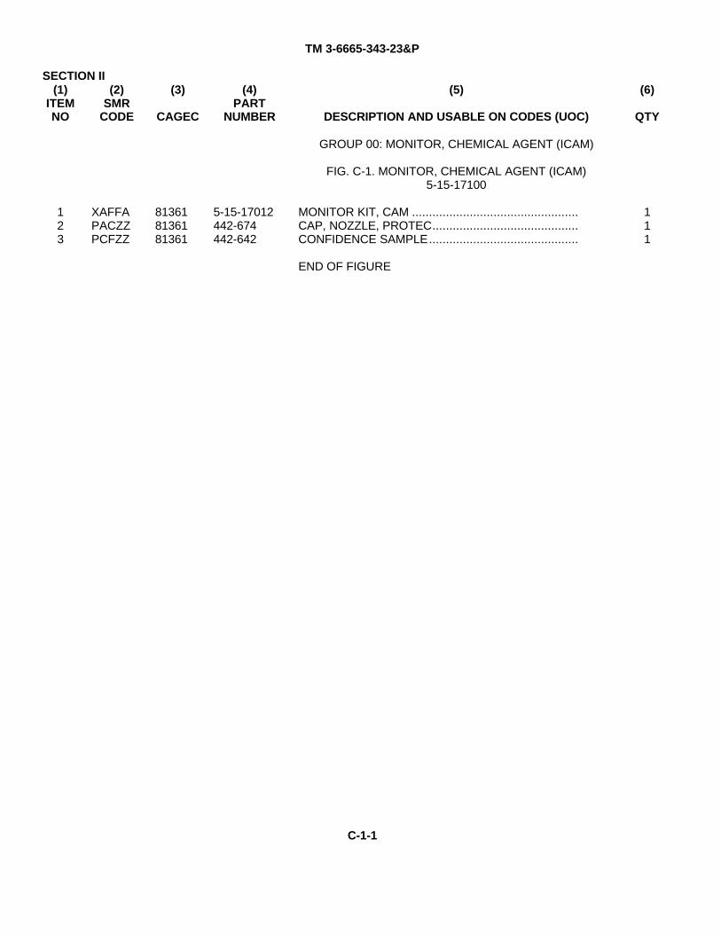
TM 3-6665-343-23&P
SECTION II(1)
ITEMNO
(2)SMR
CODE
(3)
CAGEC
(4)PART
NUMBER
(5)
DESCRIPTION AND USABLE ON CODES (UOC)
(6)
QTY
123
XAFFAPACZZPCFZZ
813618136181361
5-15-17012442-674442-642
GROUP 00: MONITOR, CHEMICAL AGENT (ICAM)
FIG. C-1. MONITOR, CHEMICAL AGENT (ICAM)5-15-17100
MONITOR KIT, CAM .................................................CAP, NOZZLE, PROTEC...........................................CONFIDENCE SAMPLE............................................
END OF FIGURE
111
C-1-1
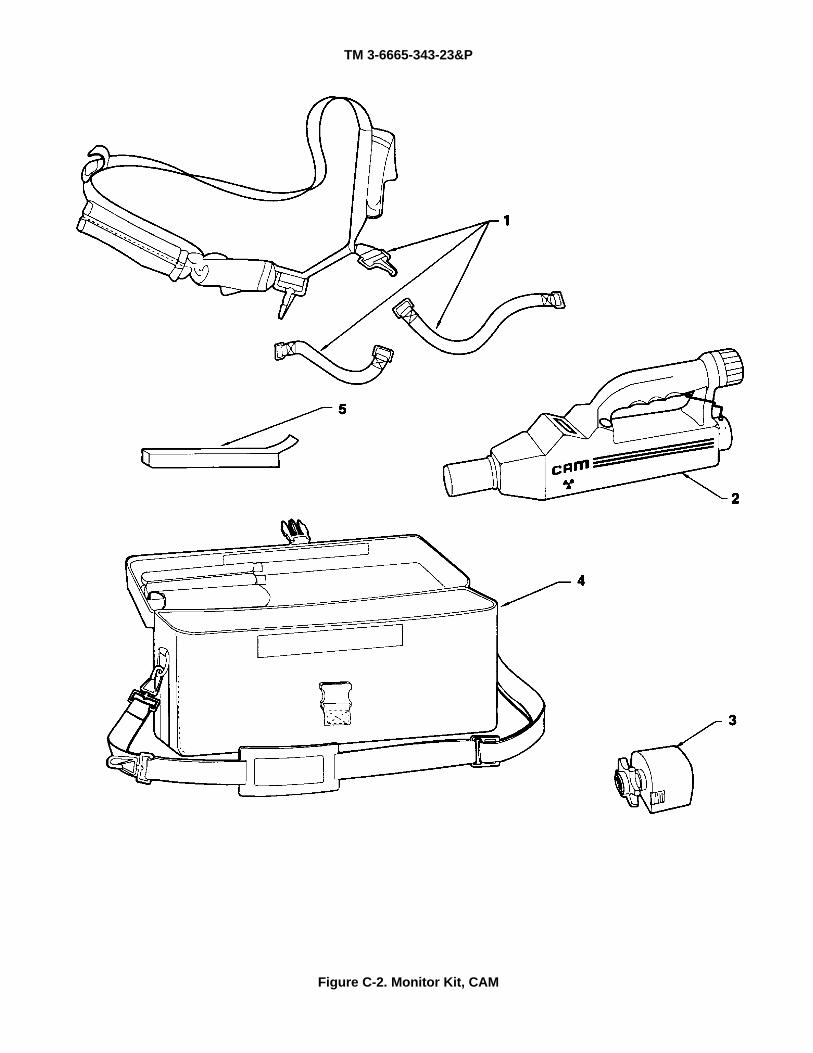
TM 3-6665-343-23&P
Figure C-2. Monitor Kit, CAM
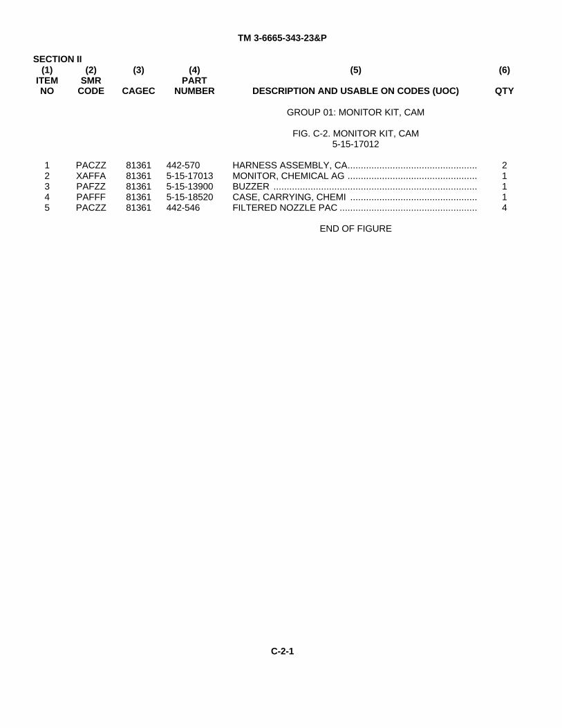
TM 3-6665-343-23&P
SECTION II(1)
ITEMNO
(2)SMR
CODE
(3)
CAGEC
(4)PART
NUMBER
(5)
DESCRIPTION AND USABLE ON CODES (UOC)
(6)
QTY
GROUP 01: MONITOR KIT, CAM
FIG. C-2. MONITOR KIT, CAM5-15-17012
12345
PACZZXAFFAPAFZZPAFFFPACZZ
8136181361813618136181361
442-5705-15-170135-15-139005-15-18520442-546
HARNESS ASSEMBLY, CA.................................................MONITOR, CHEMICAL AG .................................................BUZZER .............................................................................CASE, CARRYING, CHEMI ................................................FILTERED NOZZLE PAC ....................................................
END OF FIGURE
21114
C-2-1
TM 3-6665-343-23&P
Figure C-3. Monitor, Chemical Agent
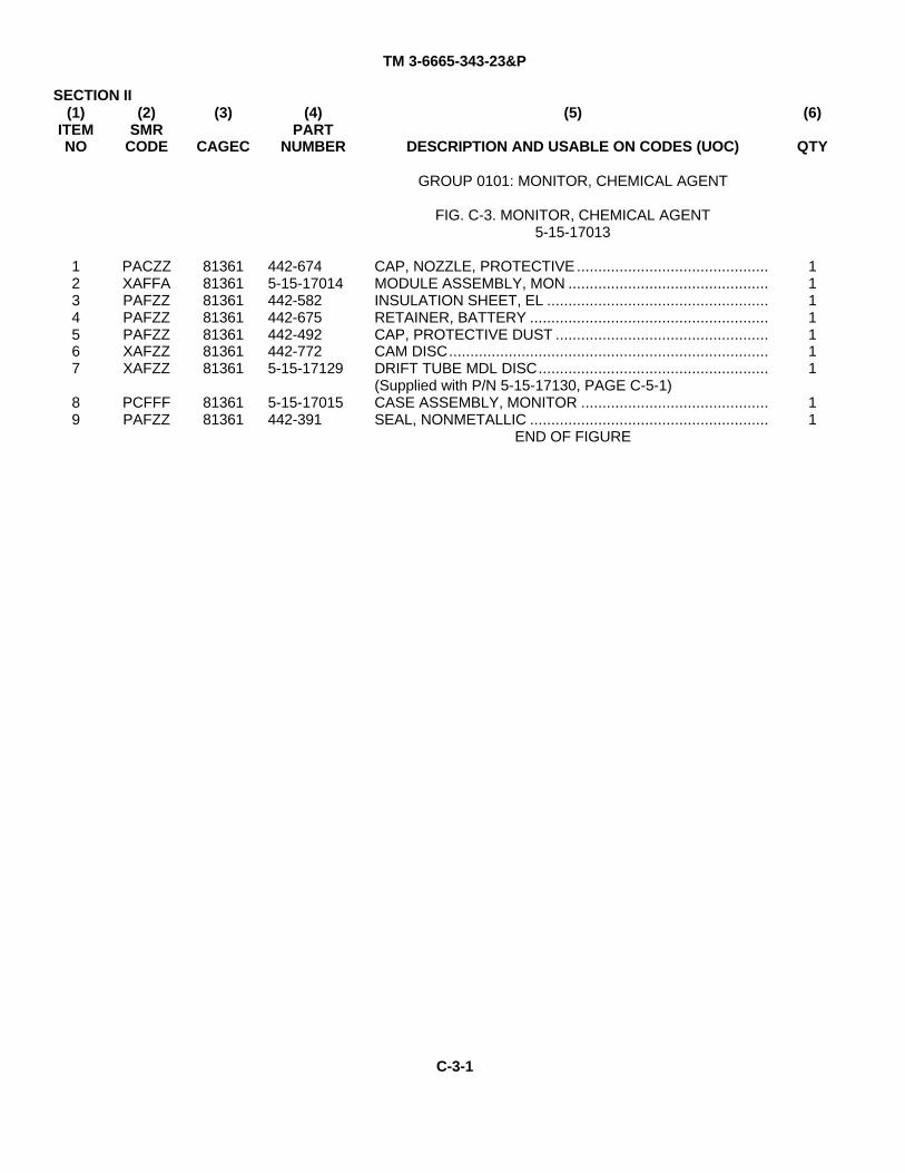
TM 3-6665-343-23&P
SECTION II(1)
ITEMNO
(2)SMR
CODE
(3)
CAGEC
(4)PART
NUMBER
(5)
DESCRIPTION AND USABLE ON CODES (UOC)
(6)
QTY
GROUP 0101: MONITOR, CHEMICAL AGENT
FIG. C-3. MONITOR, CHEMICAL AGENT5-15-17013
1234567
89
PACZZXAFFAPAFZZPAFZZPAFZZXAFZZXAFZZ
PCFFFPAFZZ
81361813618136181361813618136181361
8136181361
442-6745-15-17014442-582442-675442-492442-7725-15-17129
5-15-17015442-391
CAP, NOZZLE, PROTECTIVE .............................................MODULE ASSEMBLY, MON ...............................................INSULATION SHEET, EL ....................................................RETAINER, BATTERY ........................................................CAP, PROTECTIVE DUST ..................................................CAM DISC...........................................................................DRIFT TUBE MDL DISC......................................................(Supplied with P/N 5-15-17130, PAGE C-5-1)CASE ASSEMBLY, MONITOR ............................................SEAL, NONMETALLIC ........................................................
END OF FIGURE
1111111
11
C-3-1
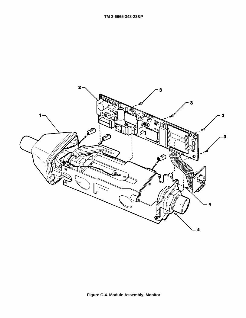
TM 3-6665-343-23&P
Figure C-4. Module Assembly, Monitor
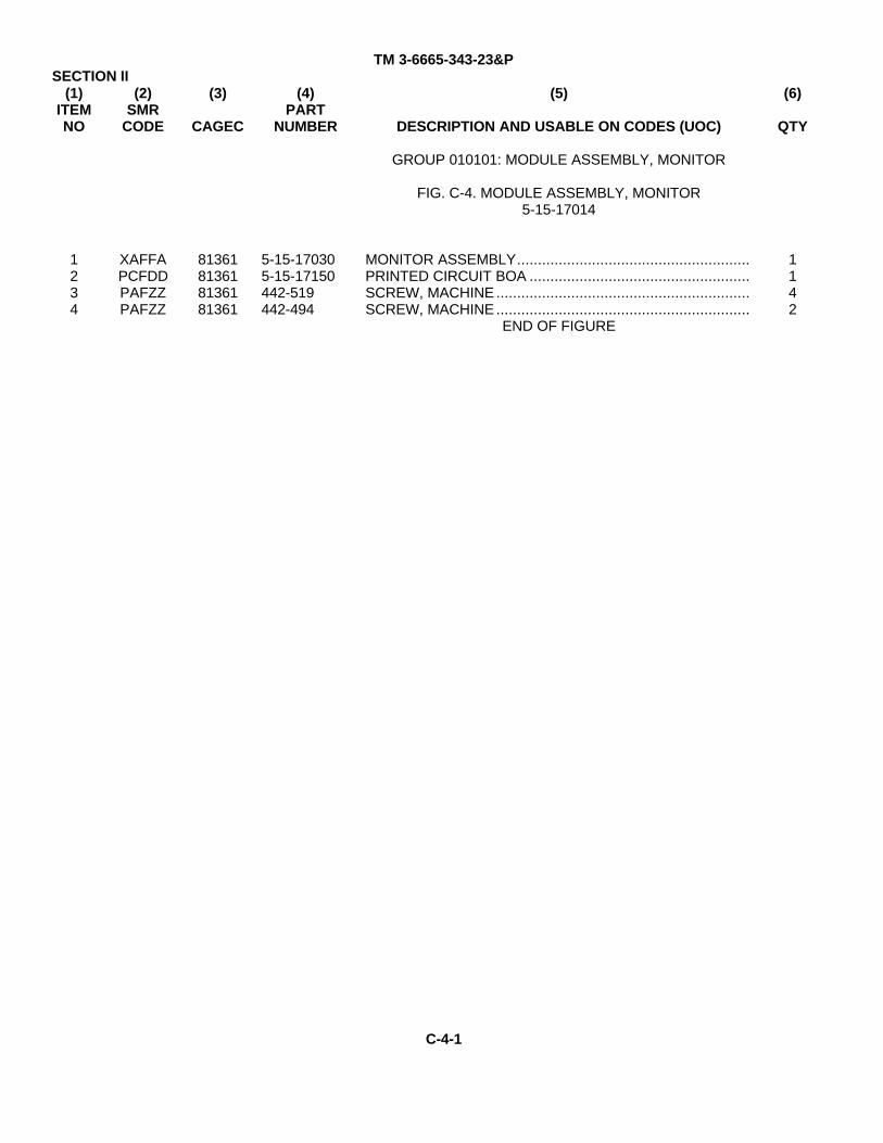
TM 3-6665-343-23&PSECTION II
(1)ITEMNO
(2)SMR
CODE
(3)
CAGEC
(4)PART
NUMBER
(5)
DESCRIPTION AND USABLE ON CODES (UOC)
(6)
QTY
GROUP 010101: MODULE ASSEMBLY, MONITOR
FIG. C-4. MODULE ASSEMBLY, MONITOR5-15-17014
1234
XAFFAPCFDDPAFZZPAFZZ
81361813618136181361
5-15-170305-15-17150442-519442-494
MONITOR ASSEMBLY........................................................PRINTED CIRCUIT BOA .....................................................SCREW, MACHINE .............................................................SCREW, MACHINE .............................................................
END OF FIGURE
1142
C-4-1
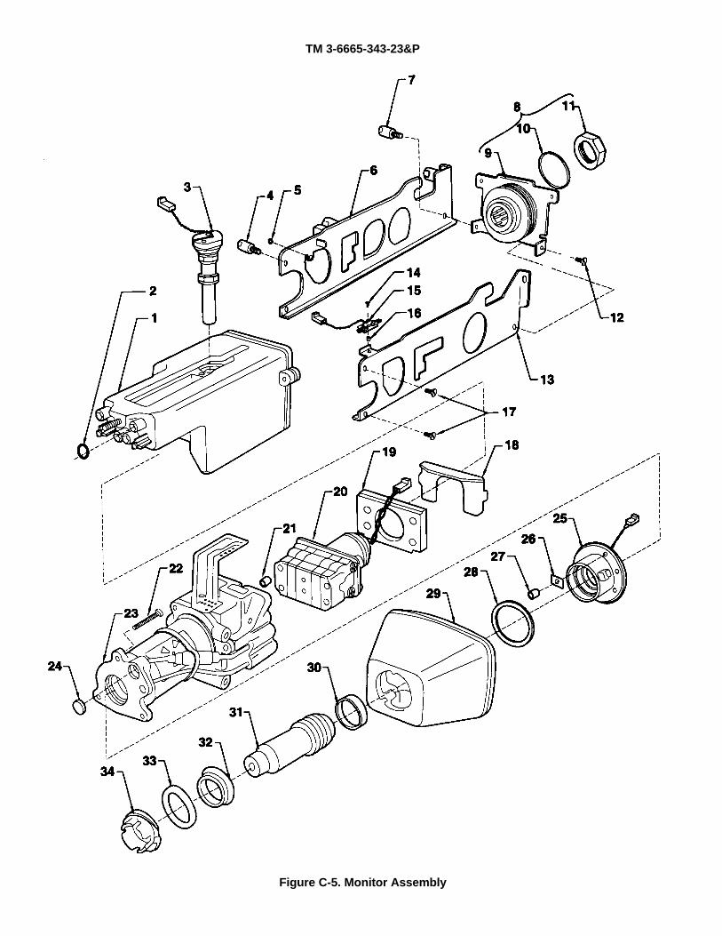
TM 3-6665-343-23&P
Figure C-5. Monitor Assembly
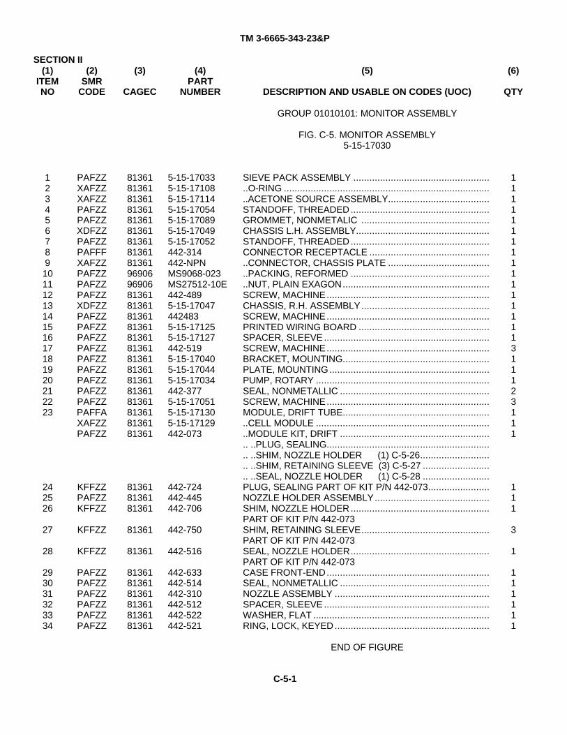
TM 3-6665-343-23&P
SECTION II(1)
ITEMNO
(2)SMR
CODE
(3)
CAGEC
(4)PART
NUMBER
(5)
DESCRIPTION AND USABLE ON CODES (UOC)
(6)
QTY
GROUP 01010101: MONITOR ASSEMBLY
FIG. C-5. MONITOR ASSEMBLY5-15-17030
1234567891011121314151617181920212223
242526
27
28
293031323334
PAFZZXAFZZXAFZZPAFZZPAFZZXDFZZPAFZZPAFFFXAFZZPAFZZPAFZZPAFZZXDFZZPAFZZPAFZZPAFZZPAFZZPAFZZPAFZZPAFZZPAFZZPAFZZPAFFAXAFZZPAFZZ
KFFZZPAFZZKFFZZ
KFFZZ
KFFZZ
PAFZZPAFZZPAFZZPAFZZPAFZZPAFZZ
81361813618136181361813618136181361813618136196906969068136181361813618136181361813618136181361813618136181361813618136181361
813618136181361
81361
81361
813618136181361813618136181361
5-15-170335-15-171085-15-171145-15-170545-15-170895-15-170495-15-17052442-314442-NPNMS9068-023MS27512-10E442-4895-15-170474424835-15-171255-15-17127442-5195-15-170405-15-170445-15-17034442-3775-15-170515-15-171305-15-17129442-073
442-724442-445442-706
442-750
442-516
442-633442-514442-310442-512442-522442-521
SIEVE PACK ASSEMBLY .....................................................O-RING ...............................................................................ACETONE SOURCE ASSEMBLY......................................STANDOFF, THREADED ....................................................GROMMET, NONMETALIC ................................................CHASSIS L.H. ASSEMBLY..................................................STANDOFF, THREADED ....................................................CONNECTOR RECEPTACLE ...............................................CONNECTOR, CHASSIS PLATE ........................................PACKING, REFORMED ......................................................NUT, PLAIN EXAGON.......................................................SCREW, MACHINE.............................................................CHASSIS, R.H. ASSEMBLY................................................SCREW, MACHINE.............................................................PRINTED WIRING BOARD .................................................SPACER, SLEEVE ..............................................................SCREW, MACHINE.............................................................BRACKET, MOUNTING.......................................................PLATE, MOUNTING............................................................PUMP, ROTARY .................................................................SEAL, NONMETALLIC ........................................................SCREW, MACHINE.............................................................MODULE, DRIFT TUBE.........................................................CELL MODULE ...................................................................MODULE KIT, DRIFT .......................................................... ..PLUG, SEALING............................................................... ..SHIM, NOZZLE HOLDER (1) C-5-26............................ ..SHIM, RETAINING SLEEVE (3) C-5-27 ........................... ..SEAL, NOZZLE HOLDER (1) C-5-28 .........................PLUG, SEALING PART OF KIT P/N 442-073.......................NOZZLE HOLDER ASSEMBLY...........................................SHIM, NOZZLE HOLDER....................................................PART OF KIT P/N 442-073SHIM, RETAINING SLEEVE................................................PART OF KIT P/N 442-073SEAL, NOZZLE HOLDER....................................................PART OF KIT P/N 442-073CASE FRONT-END.............................................................SEAL, NONMETALLIC ........................................................NOZZLE ASSEMBLY ..........................................................SPACER, SLEEVE ..............................................................WASHER, FLAT ..................................................................RING, LOCK, KEYED..........................................................
END OF FIGURE
1111111111111111311123111
111
3
1
111111
C-5-1
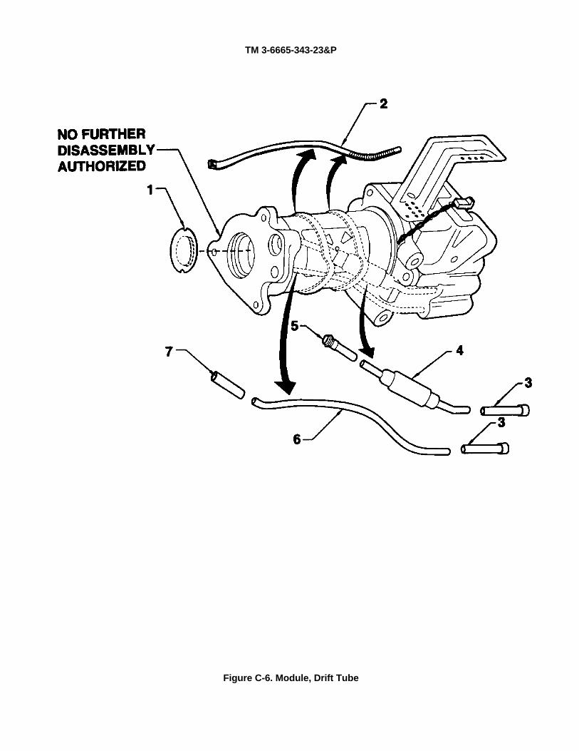
TM 3-6665-343-23&P
Figure C-6. Module, Drift Tube
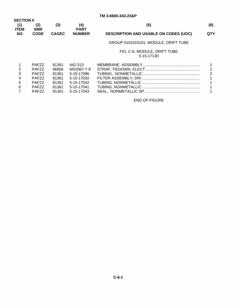
TM 3-6665-343-23&PSECTION II
(1)ITEMNO
(2)SMR
CODE
(3)
CAGEC
(4)PART
NUMBER
(5)
DESCRIPTION AND USABLE ON CODES (UOC)
(6)
QTY
GROUP 0101010101: MODULE, DRIFT TUBE
FIG. C-6. MODULE, DRIFT TUBE5-15-17130
1234567
PAFZZPAFZZPAFZZPAFZZPAFZZPAFZZPAFZZ
81361969068136181361813618136181361
442-313MS3367-7-95-15-170865-15-170325-15-170425-15-170415-15-17043
MEMBRANE ASSEMBLY ...................................................STRAP, TIEDOWN, ELECT.................................................TUBING, NONMETALLIC ...................................................FILTER ASSEMBLY, DRI ....................................................TUBING, NONMETALLIC ....................................................TUBING, NONMETALLIC ....................................................SEAL, NONMETALLIC SP..................................................
END OF FIGURE
1221111
C-6-1
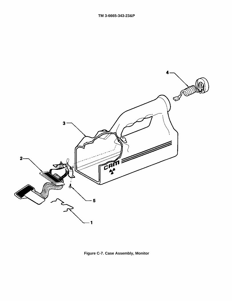
TM 3-6665-343-23&P
Figure C-7. Case Assembly, Monitor
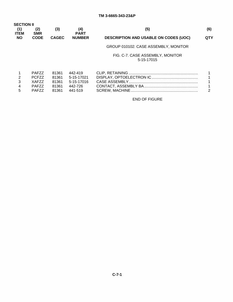
TM 3-6665-343-23&P
SECTION II(1)
ITEMNO
(2)SMR
CODE
(3)
CAGEC
(4)PART
NUMBER
(5)
DESCRIPTION AND USABLE ON CODES (UOC)
(6)
QTY
GROUP 010102: CASE ASSEMBLY, MONITOR
FIG. C-7. CASE ASSEMBLY, MONITOR5-15-17015
12345
PAFZZPCFZZXAFZZPAFZZPAFZZ
8136181361813618136181361
442-4195-15-170215-15-17016442-726441-519
CLIP, RETAINING ...............................................................DISPLAY, OPTOELECTRON IC ..........................................CASE ASSEMBLY...............................................................CONTACT, ASSEMBLY BA.................................................SCREW, MACHINE .............................................................
END OF FIGURE
11112
C-7-1
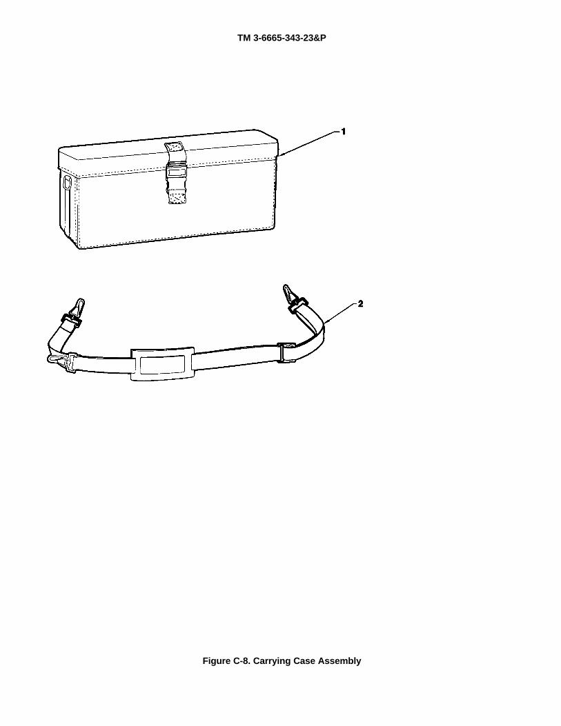
TM 3-6665-343-23&P
Figure C-8. Carrying Case Assembly
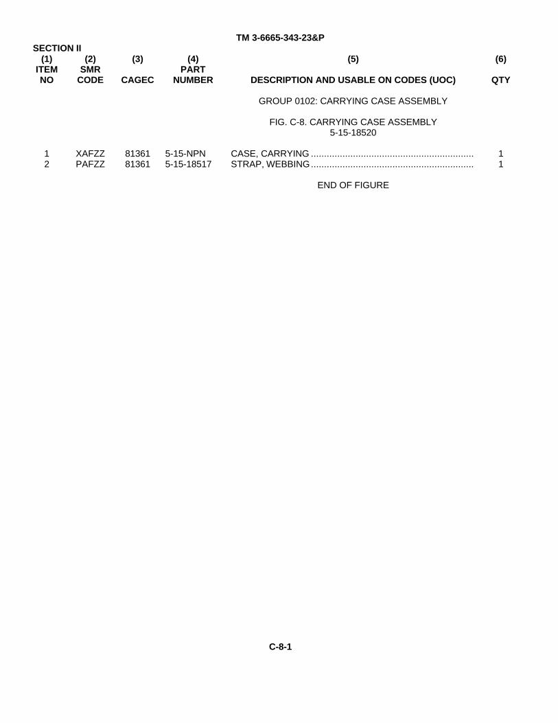
TM 3-6665-343-23&PSECTION II
(1)ITEMNO
(2)SMR
CODE
(3)
CAGEC
(4)PART
NUMBER
(5)
DESCRIPTION AND USABLE ON CODES (UOC)
(6)
QTY
GROUP 0102: CARRYING CASE ASSEMBLY
FIG. C-8. CARRYING CASE ASSEMBLY5-15-18520
12
XAFZZPAFZZ
8136181361
5-15-NPN5-15-18517
CASE, CARRYING ..............................................................STRAP, WEBBING..............................................................
END OF FIGURE
11
C-8-1

TM 3-6665-343-23&P
Section III. SPECIAL TOOLS LIST.
Not Applicable.
C-9-1
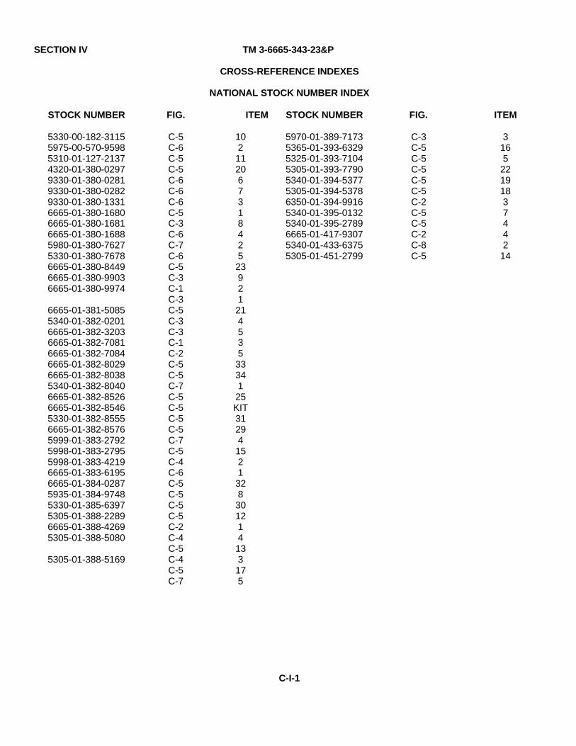
SECTION IV TM 3-6665-343-23&P
CROSS-REFERENCE INDEXES
NATIONAL STOCK NUMBER INDEX
STOCK NUMBER FIG. ITEM STOCK NUMBER FIG. ITEM
5330-00-182-31155975-00-570-95985310-01-127-21374320-01-380-02979330-01-380-02819330-01-380-02829330-01-380-13316665-01-380-16806665-01-380-16816665-01-380-16885980-01-380-76275330-01-380-76786665-01-380-84496665-01-380-99036665-01-380-9974
6665-01-381-50855340-01-382-02016665-01-382-32036665-01-382-70816665-01-382-70846665-01-382-80296665-01-382-80385340-01-382-80406665-01-382-85266665-01-382-85465330-01-382-85556665-01-382-85765999-01-383-27925998-01-383-27955998-01-383-42196665-01-383-61956665-01-384-02875935-01-384-97485330-01-385-63975305-01-388-22896665-01-388-42695305-01-388-5080
5305-01-388-5169
C-5C-6C-5C-5C-6C-6C-6C-5C-3C-6C-7C-6C-5C-3C-1C-3C-5C-3C-3C-1C-2C-5C-5C-7C-5C-5C-5C-5C-7C-5C-4C-6C-5C-5C-5C-5C-2C-4C-5C-4C-5C-7
102112067318425239212145353334125KIT312941521328301214133175
5970-01-389-71735365-01-393-63295325-01-393-71045305-01-393-77905340-01-394-53775305-01-394-53786350-01-394-99165340-01-395-01325340-01-395-27896665-01-417-93075340-01-433-63755305-01-451-2799
C-3C-5C-5C-5C-5C-5C-2C-5C-5C-2C-8C-5
3165
22191837442
14
C-I-1
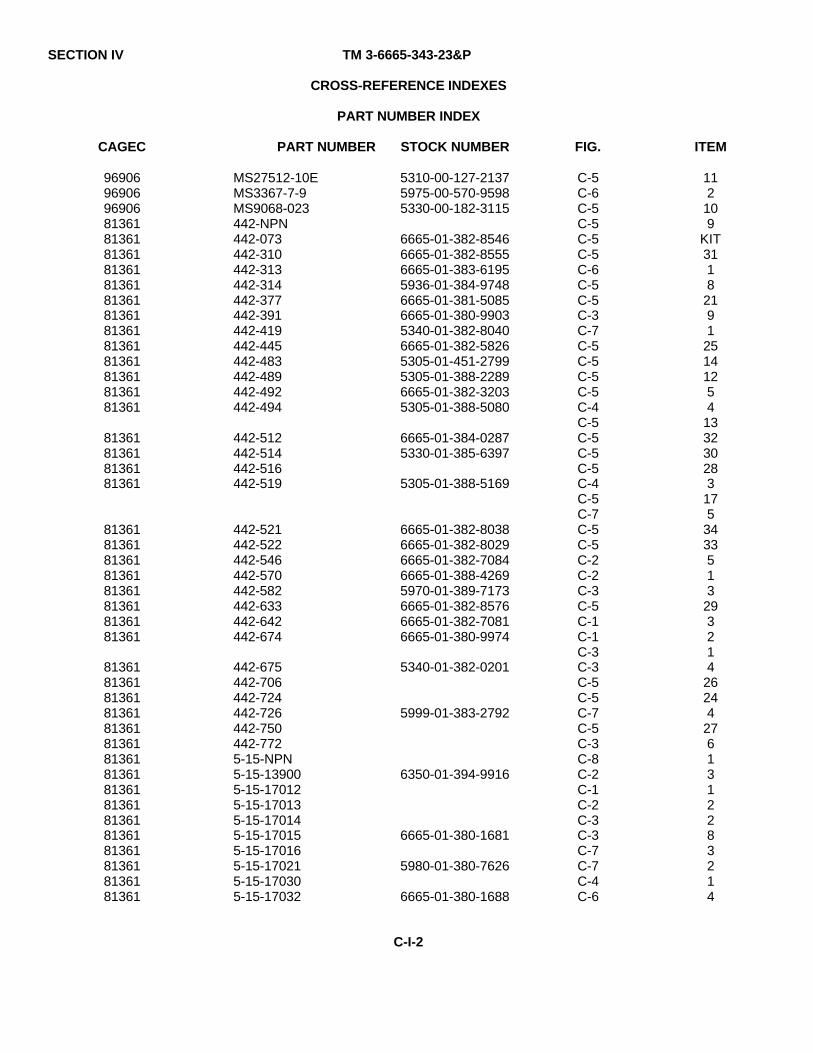
SECTION IV TM 3-6665-343-23&P
CROSS-REFERENCE INDEXES
PART NUMBER INDEX
CAGEC PART NUMBER STOCK NUMBER FIG. ITEM
96906969069690681361813618136181361813618136181361813618136181361813618136181361
81361813618136181361
8136181361813618136181361813618136181361
81361813618136181361813618136181361813618136181361813618136181361813618136181361
MS27512-10EMS3367-7-9MS9068-023442-NPN442-073442-310442-313442-314442-377442-391442-419442-445442-483442-489442-492442-494
442-512442-514442-516442-519
442-521442-522442-546442-570442-582442-633442-642442-674
442-675442-706442-724442-726442-750442-7725-15-NPN5-15-139005-15-170125-15-170135-15-170145-15-170155-15-170165-15-170215-15-170305-15-17032
5310-00-127-21375975-00-570-95985330-00-182-3115
6665-01-382-85466665-01-382-85556665-01-383-61955936-01-384-97486665-01-381-50856665-01-380-99035340-01-382-80406665-01-382-58265305-01-451-27995305-01-388-22896665-01-382-32035305-01-388-5080
6665-01-384-02875330-01-385-6397
5305-01-388-5169
6665-01-382-80386665-01-382-80296665-01-382-70846665-01-388-42695970-01-389-71736665-01-382-85766665-01-382-70816665-01-380-9974
5340-01-382-0201
5999-01-383-2792
6350-01-394-9916
6665-01-380-1681
5980-01-380-7626
6665-01-380-1688
C-5C-6C-5C-5C-5C-5C-6C-5C-5C-3C-7C-5C-5C-5C-5C-4C-5C-5C-5C-5C-4C-5C-7C-5C-5C-2C-2C-3C-5C-1C-1C-3C-3C-5C-5C-7C-5C-3C-8C-2C-1C-2C-3C-3C-7C-7C-4C-6
112
109
KIT3118
2191
25141254
133230283
175
3433513
293214
26244
2761312283214
C-I-2
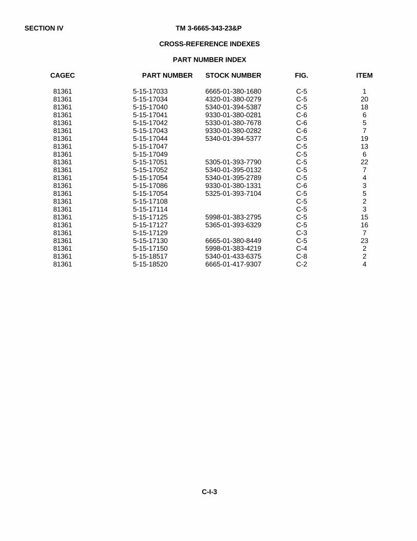
SECTION IV TM 3-6665-343-23&P
CROSS-REFERENCE INDEXES
PART NUMBER INDEX
CAGEC PART NUMBER STOCK NUMBER FIG. ITEM
8136181361813618136181361813618136181361813618136181361813618136181361813618136181361813618136181361813618136181361
5-15-170335-15-170345-15-170405-15-170415-15-170425-15-170435-15-170445-15-170475-15-170495-15-170515-15-170525-15-170545-15-170865-15-170545-15-171085-15-171145-15-171255-15-171275-15-171295-15-171305-15-171505-15-185175-15-18520
6665-01-380-16804320-01-380-02795340-01-394-53879330-01-380-02815330-01-380-76789330-01-380-02825340-01-394-5377
5305-01-393-77905340-01-395-01325340-01-395-27899330-01-380-13315325-01-393-7104
5998-01-383-27955365-01-393-6329
6665-01-380-84495998-01-383-42195340-01-433-63756665-01-417-9307
C-5C-5C-5C-6C-6C-6C-5C-5C-5C-5C-5C-5C-6C-5C-5C-5C-5C-5C-3C-5C-4C-8C-2
12018657
19136
22743523
15167
23224
C-I-3
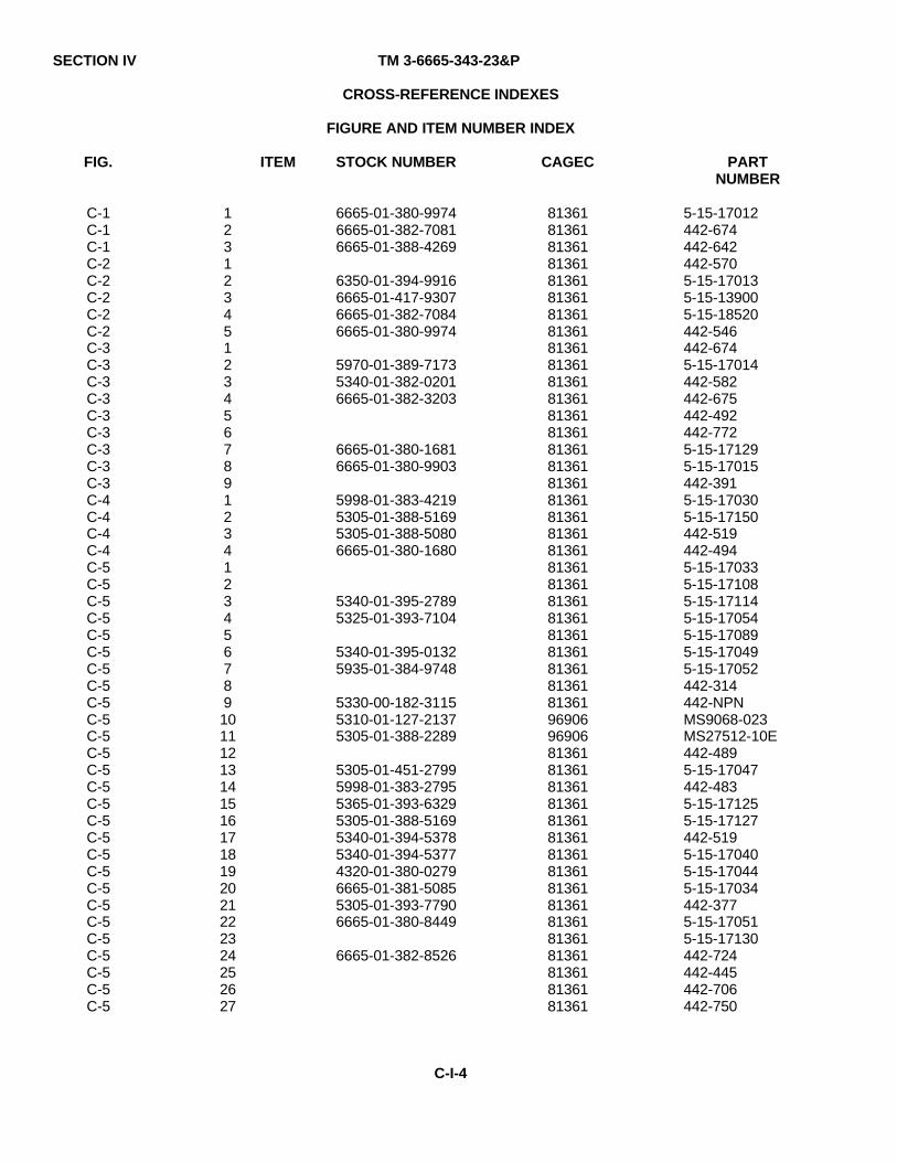
SECTION IV TM 3-6665-343-23&P
CROSS-REFERENCE INDEXES
FIGURE AND ITEM NUMBER INDEX
FIG. ITEM STOCK NUMBER CAGEC PARTNUMBER
C-1C-1C-1C-2C-2C-2C-2C-2C-3C-3C-3C-3C-3C-3C-3C-3C-3C-4C-4C-4C-4C-5C-5C-5C-5C-5C-5C-5C-5C-5C-5C-5C-5C-5C-5C-5C-5C-5C-5C-5C-5C-5C-5C-5C-5C-5C-5C-5
123123451234567891234123456789101112131415161718192021222324252627
6665-01-380-99746665-01-382-70816665-01-388-4269
6350-01-394-99166665-01-417-93076665-01-382-70846665-01-380-9974
5970-01-389-71735340-01-382-02016665-01-382-3203
6665-01-380-16816665-01-380-9903
5998-01-383-42195305-01-388-51695305-01-388-50806665-01-380-1680
5340-01-395-27895325-01-393-7104
5340-01-395-01325935-01-384-9748
5330-00-182-31155310-01-127-21375305-01-388-2289
5305-01-451-27995998-01-383-27955365-01-393-63295305-01-388-51695340-01-394-53785340-01-394-53774320-01-380-02796665-01-381-50855305-01-393-77906665-01-380-8449
6665-01-382-8526
813618136181361813618136181361813618136181361813618136181361813618136181361813618136181361813618136181361813618136181361813618136181361813618136181361969069690681361813618136181361813618136181361813618136181361813618136181361813618136181361
5-15-17012442-674442-642442-5705-15-170135-15-139005-15-18520442-546442-6745-15-17014442-582442-675442-492442-7725-15-171295-15-17015442-3915-15-170305-15-17150442-519442-4945-15-170335-15-171085-15-171145-15-170545-15-170895-15-170495-15-17052442-314442-NPNMS9068-023MS27512-10E442-4895-15-17047442-4835-15-171255-15-17127442-5195-15-170405-15-170445-15-17034442-3775-15-170515-15-17130442-724442-445442-706442-750
C-I-4
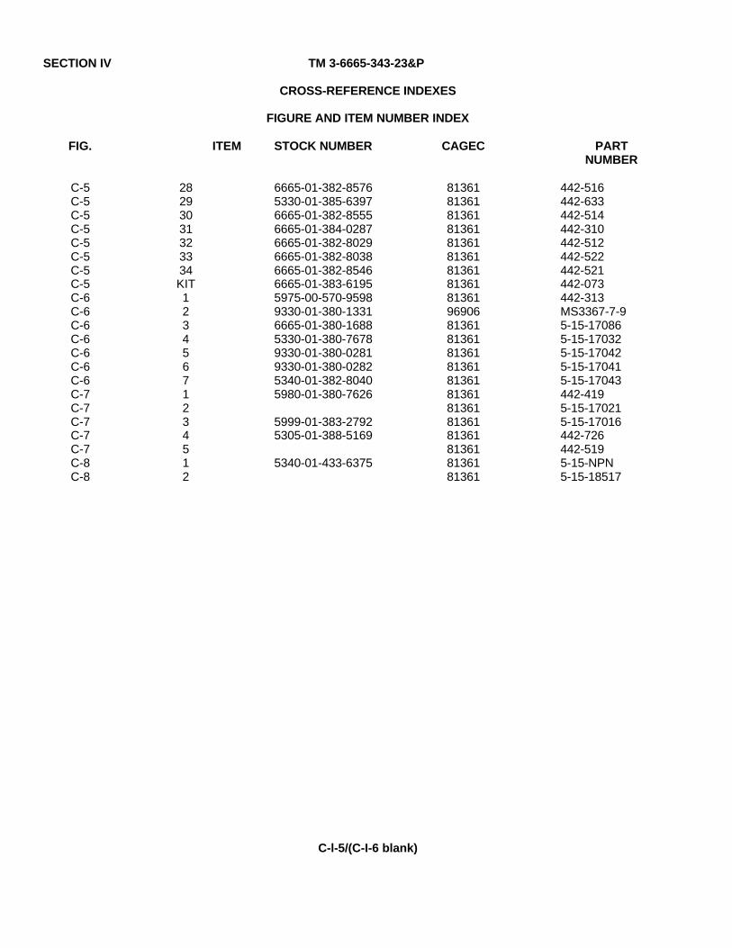
SECTION IV TM 3-6665-343-23&P
CROSS-REFERENCE INDEXES
FIGURE AND ITEM NUMBER INDEX
FIG. ITEM STOCK NUMBER CAGEC PARTNUMBER
C-5C-5C-5C-5C-5C-5C-5C-5C-6C-6C-6C-6C-6C-6C-6C-7C-7C-7C-7C-7C-8C-8
28293031323334KIT12345671234512
6665-01-382-85765330-01-385-63976665-01-382-85556665-01-384-02876665-01-382-80296665-01-382-80386665-01-382-85466665-01-383-61955975-00-570-95989330-01-380-13316665-01-380-16885330-01-380-76789330-01-380-02819330-01-380-02825340-01-382-80405980-01-380-7626
5999-01-383-27925305-01-388-5169
5340-01-433-6375
81361813618136181361813618136181361813618136196906813618136181361813618136181361813618136181361813618136181361
442-516442-633442-514442-310442-512442-522442-521442-073442-313MS3367-7-95-15-170865-15-170325-15-170425-15-170415-15-17043442-4195-15-170215-15-17016442-726442-5195-15-NPN5-15-18517
C-l-5/(C-I-6 blank)

TM 3-6665-343-23&PAPPENDIX D
EXPENDABLE AND DURABLE ITEMS LIST
Section I. INTRODUCTION
D-1. SCOPE.
This appendix lists expendable and durable items that you will need to operate and maintain the Chemical Agent Monitor(CAM). This listing is for information only and is not authority to requisition the listed items. These items are authorized toyou by CTA 50-970, Expendable/Durable Items (except medical, Class V repair parts and heraldic items) or CTA 8-100,Army Medical Department Expendable/Durable Items.
D-2. EXPLANATION OF COLUMNS.
a. Column (1) - Item Number. This number is assigned to the entry in the listing and is referenced inthe narrative instructions to identify the item (e.g., "Use gloves, Item 4, App. D ").
b. Column (2) - Level. This column identifies the lowest level of maintenance that requires the listeditem (C-Operator/Crew, O - Unit Maintenance, F - Direct Support Maintenance).
c. Column (3) - National Stock Number. This is the National stock number assigned to the item which you canuse to requisition it.
d. Column (4) - Description. Indicates the item name, description, (CAGEC) and part number. This provides theother information you need to identify the item.
e. Column (5) - Unit of Measure (U/M). this code shows the physical measurement or count of an item, such asgallon (GL), each (EA), dozen (DZ), gross (GR), etc. If the unit of measure differs from the unit of issue, requisition thelowest unit of issue that will satisfy your requirements.
D-1
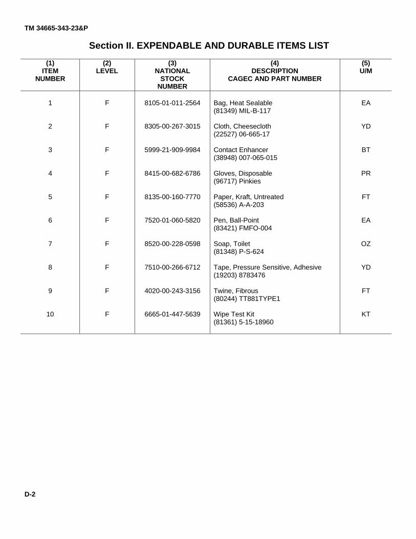
TM 34665-343-23&P
Section II. EXPENDABLE AND DURABLE ITEMS LIST
(1)ITEM
NUMBER
(2)LEVEL
(3)NATIONAL
STOCKNUMBER
(4)DESCRIPTION
CAGEC AND PART NUMBER
(5)U/M
1
2
3
4
5
6
7
8
9
10
F
F
F
F
F
F
F
F
F
F
8105-01-011-2564
8305-00-267-3015
5999-21-909-9984
8415-00-682-6786
8135-00-160-7770
7520-01-060-5820
8520-00-228-0598
7510-00-266-6712
4020-00-243-3156
6665-01-447-5639
Bag, Heat Sealable(81349) MIL-B-117
Cloth, Cheesecloth(22527) 06-665-17
Contact Enhancer(38948) 007-065-015
Gloves, Disposable(96717) Pinkies
Paper, Kraft, Untreated(58536) A-A-203
Pen, Ball-Point(83421) FMFO-004
Soap, Toilet(81348) P-S-624
Tape, Pressure Sensitive, Adhesive(19203) 8783476
Twine, Fibrous(80244) TT881TYPE1
Wipe Test Kit(81361) 5-15-18960
EA
YD
BT
PR
FT
EA
OZ
YD
FT
KT
D-2
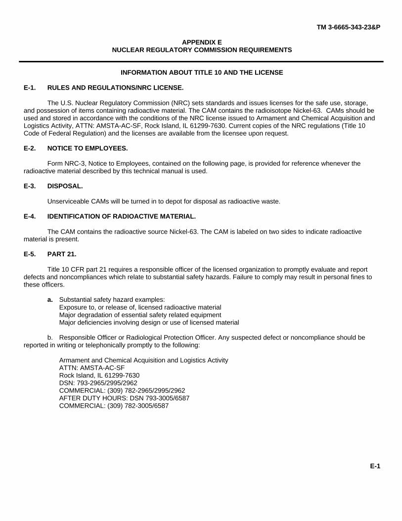
TM 3-6665-343-23&P
APPENDIX ENUCLEAR REGULATORY COMMISSION REQUIREMENTS
INFORMATION ABOUT TITLE 10 AND THE LICENSE
E-1. RULES AND REGULATIONS/NRC LICENSE.
The U.S. Nuclear Regulatory Commission (NRC) sets standards and issues licenses for the safe use, storage,and possession of items containing radioactive material. The CAM contains the radioisotope Nickel-63. CAMs should beused and stored in accordance with the conditions of the NRC license issued to Armament and Chemical Acquisition andLogistics Activity, ATTN: AMSTA-AC-SF, Rock Island, IL 61299-7630. Current copies of the NRC regulations (Title 10Code of Federal Regulation) and the licenses are available from the licensee upon request.
E-2. NOTICE TO EMPLOYEES.
Form NRC-3, Notice to Employees, contained on the following page, is provided for reference whenever theradioactive material described by this technical manual is used.
E-3. DISPOSAL.
Unserviceable CAMs will be turned in to depot for disposal as radioactive waste.
E-4. IDENTIFICATION OF RADIOACTIVE MATERIAL.
The CAM contains the radioactive source Nickel-63. The CAM is labeled on two sides to indicate radioactivematerial is present.
E-5. PART 21.
Title 10 CFR part 21 requires a responsible officer of the licensed organization to promptly evaluate and reportdefects and noncompliances which relate to substantial safety hazards. Failure to comply may result in personal fines tothese officers.
a. Substantial safety hazard examples:Exposure to, or release of, licensed radioactive materialMajor degradation of essential safety related equipmentMajor deficiencies involving design or use of licensed material
b. Responsible Officer or Radiological Protection Officer. Any suspected defect or noncompliance should bereported in writing or telephonically promptly to the following:
Armament and Chemical Acquisition and Logistics ActivityATTN: AMSTA-AC-SFRock Island, IL 61299-7630DSN: 793-2965/2995/2962COMMERCIAL: (309) 782-2965/2995/2962AFTER DUTY HOURS: DSN 793-3005/6587COMMERCIAL: (309) 782-3005/6587
E-1

TM 3-6665-343-23&P
E-2
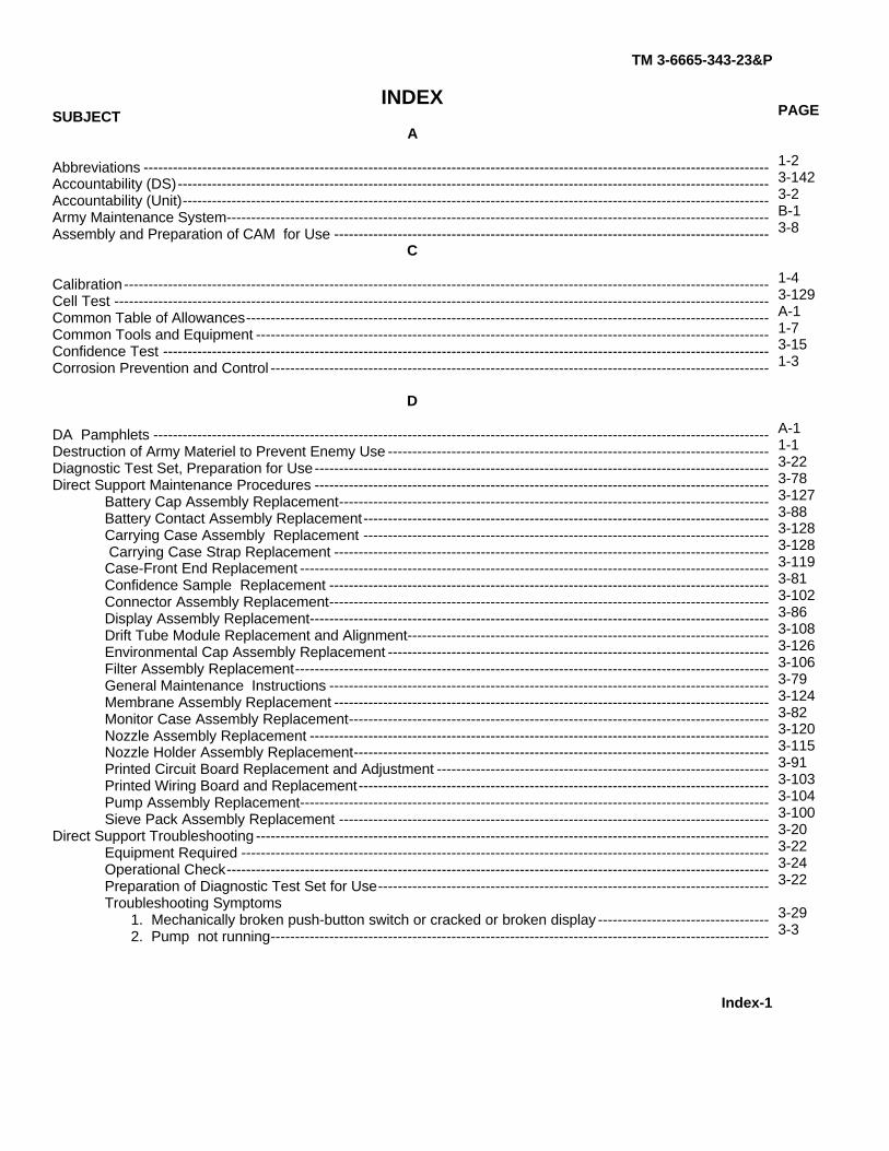
TM 3-6665-343-23&P
INDEXSUBJECT
A
Abbreviations --------------------------------------------------------------------------------------------------------------------------------Accountability (DS)-------------------------------------------------------------------------------------------------------------------------Accountability (Unit)------------------------------------------------------------------------------------------------------------------------Army Maintenance System---------------------------------------------------------------------------------------------------------------Assembly and Preparation of CAM for Use -----------------------------------------------------------------------------------------
C
Calibration------------------------------------------------------------------------------------------------------------------------------------Cell Test --------------------------------------------------------------------------------------------------------------------------------------Common Table of Allowances-----------------------------------------------------------------------------------------------------------Common Tools and Equipment ---------------------------------------------------------------------------------------------------------Confidence Test ----------------------------------------------------------------------------------------------------------------------------Corrosion Prevention and Control ------------------------------------------------------------------------------------------------------
D
DA Pamphlets ------------------------------------------------------------------------------------------------------------------------------Destruction of Army Materiel to Prevent Enemy Use ------------------------------------------------------------------------------Diagnostic Test Set, Preparation for Use---------------------------------------------------------------------------------------------Direct Support Maintenance Procedures ---------------------------------------------------------------------------------------------
Battery Cap Assembly Replacement----------------------------------------------------------------------------------------Battery Contact Assembly Replacement-----------------------------------------------------------------------------------Carrying Case Assembly Replacement ----------------------------------------------------------------------------------- Carrying Case Strap Replacement -----------------------------------------------------------------------------------------Case-Front End Replacement ------------------------------------------------------------------------------------------------Confidence Sample Replacement ------------------------------------------------------------------------------------------Connector Assembly Replacement------------------------------------------------------------------------------------------Display Assembly Replacement----------------------------------------------------------------------------------------------Drift Tube Module Replacement and Alignment--------------------------------------------------------------------------Environmental Cap Assembly Replacement ------------------------------------------------------------------------------Filter Assembly Replacement-------------------------------------------------------------------------------------------------General Maintenance Instructions ------------------------------------------------------------------------------------------Membrane Assembly Replacement -----------------------------------------------------------------------------------------Monitor Case Assembly Replacement--------------------------------------------------------------------------------------Nozzle Assembly Replacement ----------------------------------------------------------------------------------------------Nozzle Holder Assembly Replacement-------------------------------------------------------------------------------------Printed Circuit Board Replacement and Adjustment --------------------------------------------------------------------Printed Wiring Board and Replacement------------------------------------------------------------------------------------Pump Assembly Replacement------------------------------------------------------------------------------------------------Sieve Pack Assembly Replacement ----------------------------------------------------------------------------------------
Direct Support Troubleshooting ---------------------------------------------------------------------------------------------------------Equipment Required ------------------------------------------------------------------------------------------------------------Operational Check---------------------------------------------------------------------------------------------------------------Preparation of Diagnostic Test Set for Use--------------------------------------------------------------------------------Troubleshooting Symptoms
1. Mechanically broken push-button switch or cracked or broken display -----------------------------------2. Pump not running------------------------------------------------------------------------------------------------------
Index-1
PAGE
1-23-1423-2B-13-8
1-43-129A-11-73-151-3
A-11-13-223-783-1273-883-1283-1283-1193-813-1023-863-1083-1263-1063-793-1243-823-1203-1153-913-1033-1043-1003-203-223-243-22
3-293-3
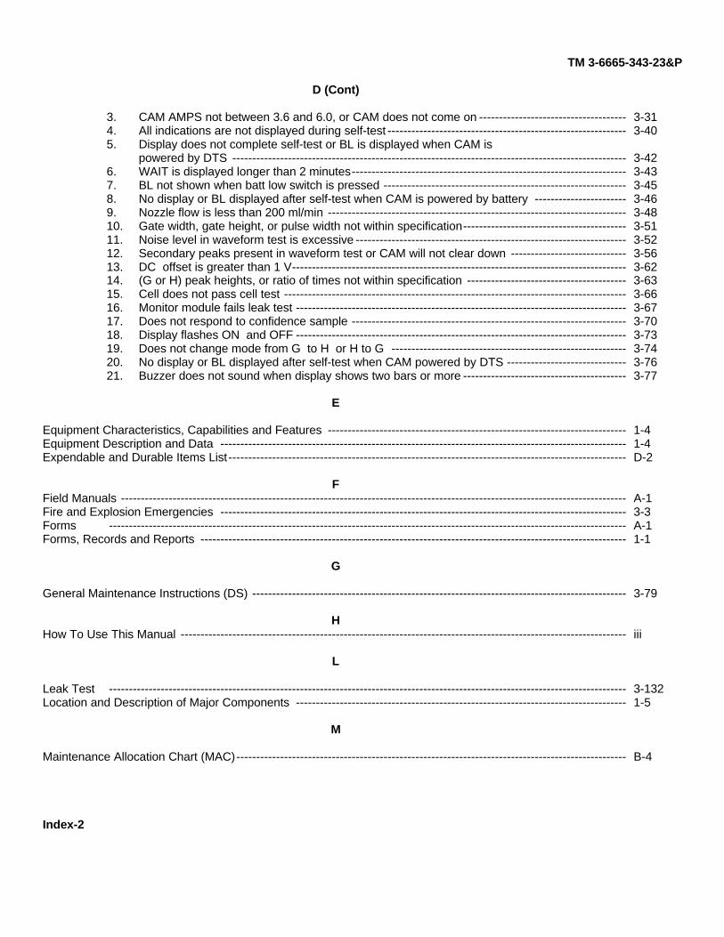
TM 3-6665-343-23&P
D (Cont)
3. CAM AMPS not between 3.6 and 6.0, or CAM does not come on -------------------------------------4. All indications are not displayed during self-test ------------------------------------------------------------5. Display does not complete self-test or BL is displayed when CAM is powered by DTS ---------------------------------------------------------------------------------------------------6. WAIT is displayed longer than 2 minutes---------------------------------------------------------------------7. BL not shown when batt low switch is pressed -------------------------------------------------------------8. No display or BL displayed after self-test when CAM is powered by battery -----------------------9. Nozzle flow is less than 200 ml/min ---------------------------------------------------------------------------10. Gate width, gate height, or pulse width not within specification-----------------------------------------11. Noise level in waveform test is excessive --------------------------------------------------------------------12. Secondary peaks present in waveform test or CAM will not clear down -----------------------------13. DC offset is greater than 1 V------------------------------------------------------------------------------------14. (G or H) peak heights, or ratio of times not within specification ----------------------------------------15. Cell does not pass cell test --------------------------------------------------------------------------------------16. Monitor module fails leak test -----------------------------------------------------------------------------------17. Does not respond to confidence sample ---------------------------------------------------------------------18. Display flashes ON and OFF -----------------------------------------------------------------------------------19. Does not change mode from G to H or H to G -----------------------------------------------------------20. No display or BL displayed after self-test when CAM powered by DTS ------------------------------21. Buzzer does not sound when display shows two bars or more -----------------------------------------
E
Equipment Characteristics, Capabilities and Features ---------------------------------------------------------------------------Equipment Description and Data ------------------------------------------------------------------------------------------------------Expendable and Durable Items List----------------------------------------------------------------------------------------------------
FField Manuals -------------------------------------------------------------------------------------------------------------------------------Fire and Explosion Emergencies ------------------------------------------------------------------------------------------------------Forms ----------------------------------------------------------------------------------------------------------------------------------Forms, Records and Reports -----------------------------------------------------------------------------------------------------------
G
General Maintenance Instructions (DS) ----------------------------------------------------------------------------------------------
HHow To Use This Manual ----------------------------------------------------------------------------------------------------------------
L
Leak Test ----------------------------------------------------------------------------------------------------------------------------------Location and Description of Major Components -----------------------------------------------------------------------------------
M
Maintenance Allocation Chart (MAC)--------------------------------------------------------------------------------------------------
3-313-40
3-423-433-453-463-483-513-523-563-623-633-663-673-703-733-743-763-77
1-41-4D-2
A-13-3A-11-1
3-79
iii
3-1321-5
B-4
Index-2
TM 3-6665-343-23&P
N
Nomenclature Cross-Reference List -------------------------------------------------------------------------------------------------Nuclear Regulatory Commission Requirements -----------------------------------------------------------------------------------
O
Operational Check -------------------------------------------------------------------------------------------------------------------------
P
Preparation for Storage or Shipment (DS) -------------------------------------------------------------------------------------------Preparation for Storage or Shipment (Unit) -----------------------------------------------------------------------------------------Preparation of Diagnostic Test Set for Use ------------------------------------------------------------------------------------------Principles of Operation -------------------------------------------------------------------------------------------------------------------Pump Test ----------------------------------------------------------------------------------------------------------------------------------Purpose of Equipment---------------------------------------------------------------------------------------------------------------------
R
Radiological Safety Instructions --------------------------------------------------------------------------------------------------------References ----------------------------------------------------------------------------------------------------------------------------------Repair Parts and Special Tools List----------------------------------------------------------------------------------------------------Section I Introduction ----------------------------------------------------------------------------------------------------------------------Section II Repair Parts List --------------------------------------------------------------------------------------------------------------Section III Special Tools List ------------------------------------------------------------------------------------------------------------Section IV Cross-Reference Indexes -------------------------------------------------------------------------------------------------Reporting Equipment Improvement Recommendations (EIR)-------------------------------------------------------------------Regulations ----------------------------------------------------------------------------------------------------------------------------------
S
Safety, Care and Handling --------------------------------------------------------------------------------------------------------------Self-Test ----------------------------------------------------------------------------------------------------------------------------------Service Upon Receipt --------------------------------------------------------------------------------------------------------------------Shipment (DS) ------------------------------------------------------------------------------------------------------------------------------Shipment (Unit) -----------------------------------------------------------------------------------------------------------------------------Soldier Training Publications -----------------------------------------------------------------------------------------------------------Special Tools, TMDE and Support Equipment -------------------------------------------------------------------------------------Stock Number Cross Reference Indexes---------------------------------------------------------------------------------------------Storage (DS)---------------------------------------------------------------------------------------------------------------------------------Storage (Unit)--------------------------------------------------------------------------------------------------------------------------------
TTechnical Bulletins -------------------------------------------------------------------------------------------------------------------------Technical Manuals -------------------------------------------------------------------------------------------------------------------------Tests
Cell Test----------------------------------------------------------------------------------------------------------------------------Leak Test --------------------------------------------------------------------------------------------------------------------------Pump Test ------------------------------------------------------------------------------------------------------------------------Waveform Test ------------------------------------------------------------------------------------------------------------------
Three Dots ----------------------------------------------------------------------------------------------------------------------------------
1-2E-1
3-24
3-1422-103-221-83-1351-1
3-1A-1C-1C-1C-1-1C-9-1C-1-11-2A-1
1-23-132-13-1422-10A-21-7C-1-13-1422-10
A-2A-2
3-1293-1323-1353-1371-11
Index-3
TM 3-6665-343-23&P
T (Cont)
Tool and Test Equipment Requirements----------------------------------------------------------------------------------------------Training Publications, Soldier -----------------------------------------------------------------------------------------------------------Troubleshooting Symptoms --------------------------------------------------------------------------------------------------------------
U
Unit Maintenance Instructions ----------------------------------------------------------------------------------------------------------Unit Preventive Maintenance Checks and Services (PMCS) -------------------------------------------------------------------Unit Troubleshooting-----------------------------------------------------------------------------------------------------------------------Troubleshooting Symptoms
1. Backlight not operating ---------------------------------------------------------------------------------------------------2. BL shown on display during operation --------------------------------------------------------------------------------3. Display does not come on or display disappears ------------------------------------------------------------------4. Display flashes on and off -----------------------------------------------------------------------------------------------5. Does not change mode from G to H or H to G ---------------------------------------------------------------------6. Does not clear down to zero or one bar in 2 minutes ------------------------------------------------------------7. Does not clear down to zero or one bar before shutdown -------------------------------------------------------8. Does not respond to confidence sample (simulant) ---------------------------------------------------------------9. One or more display indicators do not show during self-test ----------------------------------------------------10. Remains in self-test for more than 30 seconds ---------------------------------------------------------------------11. Remains in wait for longer than 2 minutes ---------------------------------------------------------------------------12. Buzzer does not sound when display shows two or more bars -------------------------------------------------
Unpacked Equipment, Checking -------------------------------------------------------------------------------------------------------Unpacking ----------------------------------------------------------------------------------------------------------------------------------
WWaveform Test -----------------------------------------------------------------------------------------------------------------------------Wipe Test ----------------------------------------------------------------------------------------------------------------------------------Work Area ----------------------------------------------------------------------------------------------------------------------------------Work Surface, Clean ----------------------------------------------------------------------------------------------------------------------
Index-4
B-5A-23-21
2-12-32-4
2-52-52-52-52-62-62-72-72-82-82-92-93-63-4
3-1373-63-13-22
DISTRIBUTION:
To be distr ibuted in accordance with the ini t ia l requirements for SPECIAL DISTRIBUTION forTM 3-6665-343-23&P
By Order of the Secretary of the Army:
DENNIS J. REIMERGeneral, United States Army
Chief of StaffOfficial:
JOEL B. HUDSONAdministrative Assistant to the
Secretary of the Army04749
I U.S. GOVERNMENT PRINTING OFFICE : 1998-646-036/60505
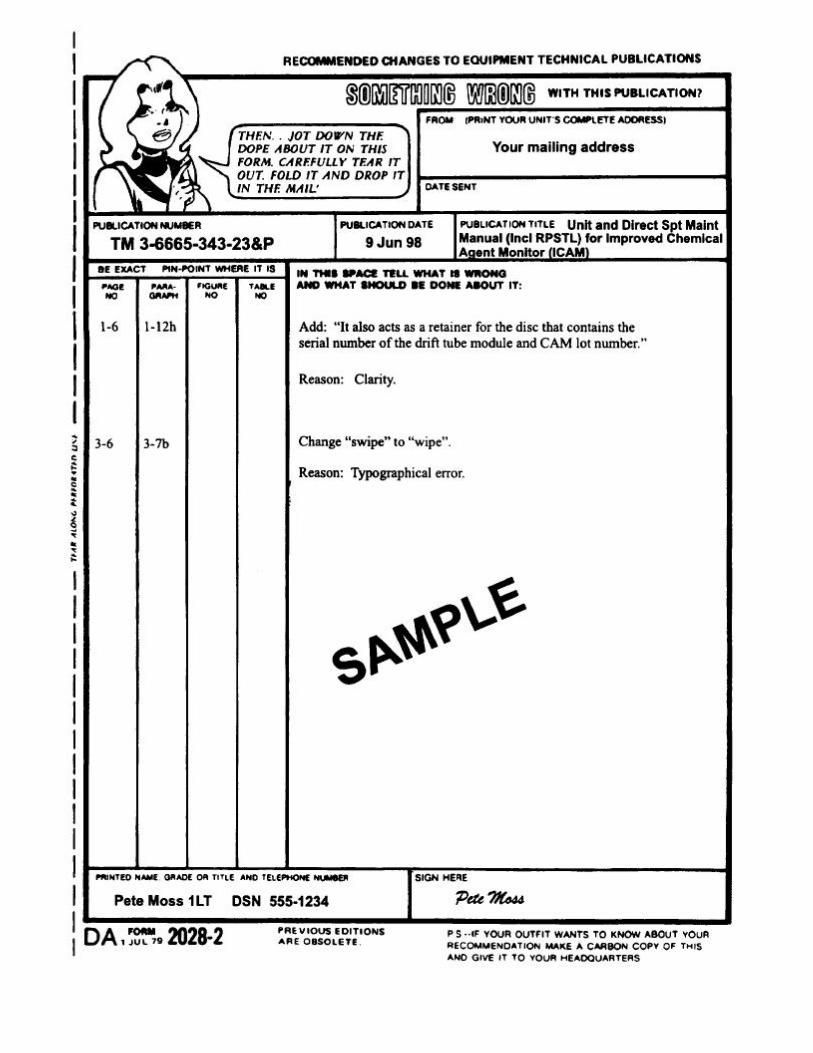
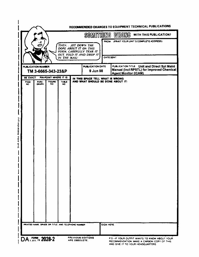

PIN: 076560-000