Embed Size (px)
Citation preview
JPL Quarterly Technical Review Volume 2, Number 4 January 1973
Index: mechanisms, optics
Helicopter Visual Aid SystemR. L Baisley
Guidance and Control Division
The results of an evaluation of police helicopter effectiveness revealed a need forimproved visual capability. A JPL program developed a method that would enhancevisual observation capability for both day and night usage and demonstrated thefeasibility of the adopted approach. This approach made use of remote pointableoptics, a display screen, a slaved covert searchlight, and a coupled camera. Theapproach was proved feasible through field testing and by judgement againstevaluation criteria.
Introduction
Recently, many law enforcement agencies have integrated helicoptersinto their patrol activities, and the trend toward their use is continuing toincrease on a national scale. Experience with these aerial patrols led torecognition of the limitations of the basic observation system. The initialsystem was comprised of the helicopter, the observer, and sometimesminimal visual aids such as binoculars or a camera. This minimal amount ofsupport equipment for the full range of police missions, conducted both atnight and during the day, limits the potential value of the helicopter system.Many attempts have been made to adapt equipment designed for otherpurposes to use on police helicopter patrols. Little effort has been made,however, to design equipment specifically for the police helicopter in itsperformance of the patrol function.
In response to this need, the Jet Propulsion Laboratory has developed avisual aid system for helicopters that is based on a set of requirementsderived from law enforcement agencies (Ref. 1).
Problem Definition and Task Objectives
The initial definition of the problem was based upon a previous civilsystems task. In this task, the Los Angeles Police Department's helicopterpatrol program was evaluated, with one element of this effort being the
72
assessment of various means by which patrol effectiveness could beincreased. A major item identified was improved visual capability.
To confirm some of these observations, and to provide a broader base ofunderstanding of the range of missions and their requirements, a nationwidesurvey was conducted involving 10 law enforcement organizations. Thissurvey:
(1) Confirmed the pressing need for improved visual capability.
(2) Pointed out that the "general patrol" mission was the most appropri-ate one upon which to focus attention.
From this, the fundamental functional requirements for a visual aid systemwere established to be:
(1) It should provide an increased field of view, coupled with thecapability to see at night without visible illumination. Minimumresolution should be equivalent to that of the unaided eye underconditions of daylight illumination.
(2) It should provide an improved capability to see during normalconditions of daylight illumination through an increased field of viewas above and with increased resolution.
(3) It must provide evidence-gathering capability through airbornephotography.
The objective of the Phase-I task was the demonstration of feasibility ofthe adopted approach. Key to the accomplishment of this objective werethe following:
(1) Establish system requirements.
(2) Perform testing of items of critical technology.
(3) Design and fabricate a breadboard model of the system.
(4) Perform a field test of the system utilizing the support of a lawenforcement agency.
System Constraints and Requirements
Physical constraints were generally bounded by the characteristics of theBell-47 G-5 helicopter, which was chosen to be the test vehicle.
The technical requirements established for a visual aid system are outlinedbelow.
(1) Mode of operation: daytime operation under ambient light condi-tions and nighttime operation using either visible illumination ornonvisible infrared illumination.
(2) Fields of view: the field of view centerline shall be pointable from thehorizon to approximately 45° below the horizon and from a forward
73
position to 90° right azimuth. In addition, it shall be capable ofvariable magnfication.
(3) Visual resolution: daylight resolution capable of resolving line pairson a 1951 Air Force resolution chart, which are separated by 50 /z,rad,and which have typical brightness values equal to or greater than1000 ft-L. At night, have the capability to distinquish line pairsseparated by 250 firad and have typical brightness due to ambientillumination of 0.001 ft-L.
(4) Display characteristics: the image shall be erect and nonreverted andshall have a minimum brightness of 1 ft-L. It shall also incorporate anindicator that shows the orientation of the line of sight relative to thevehicle. A similar indicator shall be provided for the pilot.
(5) Searchlight: the searchlight shall be slaved in azimuth and elevationto the turret subassembly and shall be capable of remote control bythe observer. The capability shall exist to remotely control the filterelements required for both visible and covert illumination of a target.
System Description
The breadboard Visual Aid System model consisted of five modularelements: the optical turret, the optical display, the searchlight, the controlconsole and the auxiliary generator. Where appropriate, components werechosen from commercially available stock, although the majority were, ofnecessity, designed and fabricated specifically for this task.
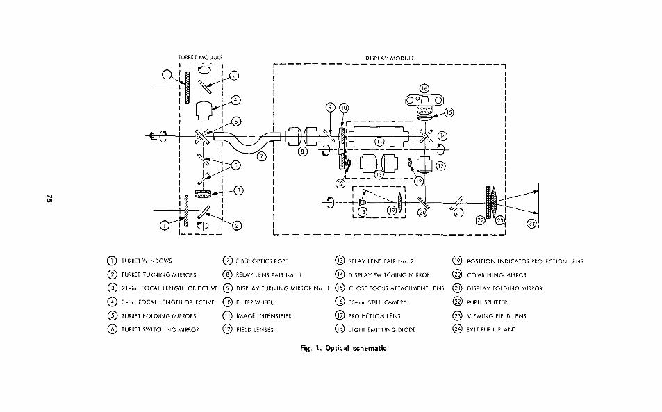
The Visual Aid System optics and electro-optics were packaged into twoseparate modules: a turret module, located underneath and forward on the"chin" of the vehicle, that contained the front objective lenses and turningmirrors, and a display module, located in the helicopter cabin in front of theobserver, that contained the balance of the optics. A flexible, image-carryingfiber-optics bundle connected the two modules. This connection allowedconsiderable freedom in location and orientation of the modules anddecoupled the vibration modes between them. A description of this system,keyed to Fig. 1, is presented below.
One of the two objective lenses (3 and 4) alternatively provided a focusedimage upon the end of the fiber optics bundle (7), the selection dependingupon the orientation of the switching mirror (6). Each of the objective lenses"looked out" through a flat glass window (1). Turning mirrors (2) werecoupled to the windows in an optical scanning head. Rotation as shownabout the common axis of the objective lenses represents an elevation scan.Rotation of the entire turret about the center line shown at the left of Fig. 1represents an azimuth scan.
Objective lens (3) was a 530-mm-focal-length, 127-mm-diam, air-spaceddoublet designed for this task by the JPL Fortran Optical Lens DesignProgram. The design was optimized for full aperture in the near infrared tocorrespond to nighttime use with infrared illumination.
74
zgCioOL
a.
C£
o<uaZZO—02)
a;
OczIozzCO
2Ou(s)
a;
Oa;
iozEOLL,
><O.
u->Q
(S)
0£ta.
ixi
a.
Da.
/^\
VT
V
oZa;
zLLJ
a:
•Cx
UJ
Oa:
y0a:
£9
0Q£
a;
OZ
.AY SWITCHI
1
oZ^^z-1
<UJ
zLLJ
Zu1—v>z>8LL.
Ou0ZOI0zza:
a.
Q
<m5EECO
I??—
LOlECTION LEN9U
J
tzzUJ
os
Q0Q
IT EMITTING
OZ^j
Q^y
Q0
©0
75
Objective lens (4) was an 85-mm, f/1.8 Takumar lens normally supplied onan amateur 35-mm camera. The lens was found to have excellent imaging inboth the near-infrared and visible regions, although a slight change in focaldistance existed between the two.
The turret turning mirrors (2) and the larger one of the two foldingmirrors (5) were large Pyrex blanks that were weight relieved by hotpressing a waffle configuration into the back of the blank. Weight-relieffactors of 35% (65% remaining) were achieved with the larger mirrors.
The fiber optics bundle (7) was an adaptation of an imaging bundledeveloped for the U. S. military helicopter-born INFANT1 Visual AidSystem. The bundle is solid at each end and flexible in between. It consistedof approximately 800,000 optical conduits, each 10 pm in diameter, groupedinto larger fibers consisting of a 6 by 6 matrix of the individual clad fibersfused together. The bundle was 4 ft in length and sheathed in plastic linksand foam rubber.
The fiber optics bundle served a number of purposes. In addition totransmitting an intact image - visible or infrared - from the turret to thedisplay without transmitting mechanical motions from one to the other, thebundle had adequate flexibility to allow its solid end at the turret to betwisted nearly a full turn each way. By twisting the bundle, image rotations,which would otherwise be introduced by the turret azimuth and elevationscan rotations, were removed from the image that was presented to thedisplay unit.
The first relay lens pair, item 8 in the display module, was two f/1.5military Starlight Scope objective lenses mounted face to face. The functionof this relay lens pair was to collect the visible or infrared light from thefiber optics bundle and reform the image either at the photocathode of theimage intensifier (11), or at the field lens (12) for further relay through thedisplay module. The Starlight Scope objectives were the only candidate shelfoptics and were deemed good enough to prove feasibility in a breadboarddemonstration. However, some aberrations were undesirably large in thepair, and a very significant light loss occurred due to an effective f/3.4 solidangle as seen from the image.
The filter wheel (10) contained, in one position, a multilayer filter to passnear-infrared and exclude visible light and, in a second position, a clear pieceof glass of an appropriate thickness to correct the visible light focal length ofthe first relay lens pair (8).
The image intensifier (11) was a cascaded three-stage, electrostaticallyimaged intensifier with an S-20 extended-red photocathode, and a P-20phosphor screen. The photocathode and the phosphor screen were each 40mm in diameter. The tube was developed under contract to the Army NightVision Laboratories for use in military applications. The tube is nominally
1 INFANT: Iroquois Night Fighter and Night Tracker
76
rated as having a total light-output-to-light-input gain of 35,000; however,production units typically have gains of 100,000.
Relay lens pair (13) was mounted in a turret with the image intensifier andcould be rotated into position to relay a visible image from the first relaypair (8). Schneider-Xenbtar, 100-mm-focal-length, f/2.8 photographic lenseswere chosen for this application. Two were used, mounted face to face.Field lenses (12) were located at the input and exit image locations tominimize vignetting, which is the principle drawback to this configuration,approximately 30% at the field edge.
Display switching mirror (14) had two operating positions: one directedlight from the image intensifier or second relay lens to a 35-mm recordingcamera (16), and the other to a projection lens (17), which forms the finalimage at the viewer end of the display.
The projection lens (17) was selected to be an f/2.9, 152-mm-focal-lengthDallmeyer Pentac. The lens was designed for infinity correction, but wasused here at a magnification of 4.4 to provide a display image 6.7 in. indiameter at the viewing field lens (23).
The viewing field lens (23) and pupil splitter (22) provided a pair of exitpupils imaged approximately 16 in. beyond the viewing field lens. The exitpupils were approximately 1 in. in diameter and spaced on center by anaverage human adult interpupillary separation of a little less than 3 in. It wasat this location that an observer positioned his eyes to look into the display.
Items 18 and 19 are a light emitting diode (LED) and a projection lens,respectively, which are incorporated into a position indicator. The LED wasmounted onto a torquer-driven assembly that was gimballed to allowreproducing the azimuth and elevation angles of the turret assembly,
The combining mirror (20) incorporated a multilayer coating thatreflected virtually all of the visible light and presented a bright scene imageto the display, yet transmitted about half of the LED illumination.Projection lens (19) then formed an image of the LED emitter area at thepupil splitter and viewing field lens. The red position dot was seen with botheyes superimposed upon the presented scene.
Optical Turret
The major functions of the optical turret illustrated in Fig. 2 were toprovide azimuth and elevation scanning for the objective lenses; focusing ofthe optics; selection of magnification; a mechanization to maintain thehorizon level at the display; image motion stabilization; support structure tomaintain alignment of the elements; and a housing to provide a protectiveenclosure against environmental conditions.
Servo-driven, the turret rotated in azimuth through 180°, from straightforward clockwise to straight backward. In elevation, the pointing limits of0° (horizontal) to 75° below the horizon were achieved. The skew rate of theturret was measured to be 22.5°/s in azimuth and 26.0°/s in elevation.
77
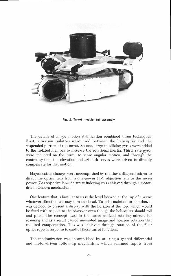
Fig. 2. Turret module, full assembly
The details of image motion stabilization combined three techniques.First, vibration isolators were used between the helicopter and thesuspended portion of the turret. Second, large stabilizing gyros were addedto the isolated member to increase the rotational inertia. Third, rate gyroswere mounted on the turret to sense angular motion, and through the
O o
control system, the elevation and azimuth servos were driven to directlycompensate for that motion.
Magnification changes were accomplished by rotating a diagonal mirror todirect the optical axis from a one-power ( I X ) objective lens to the sevenpower (7x) objective lens. Accurate indexing was achieved through a motor-driven Geneva mechanism.
One feature that is familiar to us is the level horizon at the top of a scenewhatever direction we may turn our head. To help maintain orientation, itwas decided to present a display with the horizon at the top, which wouldbe fixed with respect to the observer even though the helicopter should rolland pitch. The concept used in the turret utilized rotating mirrors forscanning and as a result caused unwanted image and horizon rotation thatrequired compensation. This was achieved through rotation of the fiberoptics rope in response to each of these turret functions.
The mechanization was accomplished by utilizing a geared differentialand motor-driven follow-up mechanism, which summed inputs from
78
elevation and azimuth axes and the switching mirror position (IX or 7X) andprovided the proper rotational position for the fiber optics rope end.
Optical Display
Several functions were provided in the display module. These were,principally, display of the image (day or night), conversion of infrared tovisible light (night), intensification of the visible or infrared image (night),and display of the turret-pointing position indicator (day or night). Certainancillary functions were mechanized: a filter wheel for selection of eitherinfrared only or hill visible; a camera for recording the scene in the displayunit; reticle illumination (night) and display tilt to accommodate the sittingheight of the various observers.
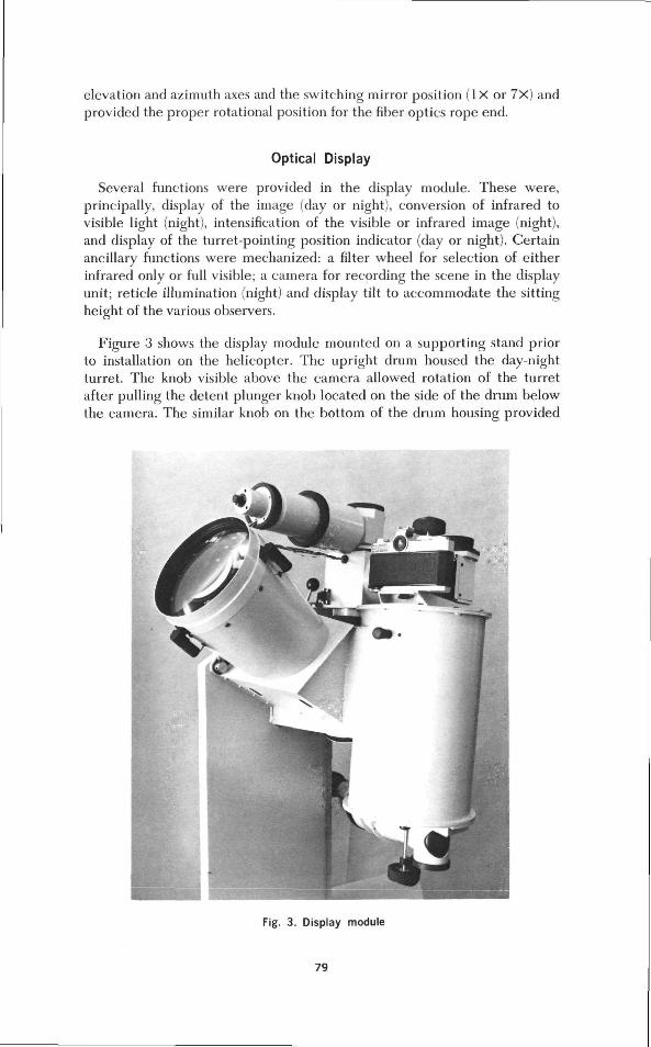
Figure 3 shows the display module mounted on a supporting stand priorto installation on the helicopter. The upright drum housed the day-nightturret. The knob visible above the camera allowed rotation of the turretafter pulling the detent plunger knob located on the side of the drum belowthe camera. The similar knob on the bottom of the drum housing provided
Fig. 3. Display module
79
for rotation of the filter wheel. The fiber optics rope entered the displaymodule from bottom far side as seen in this photograph.
Searchlight
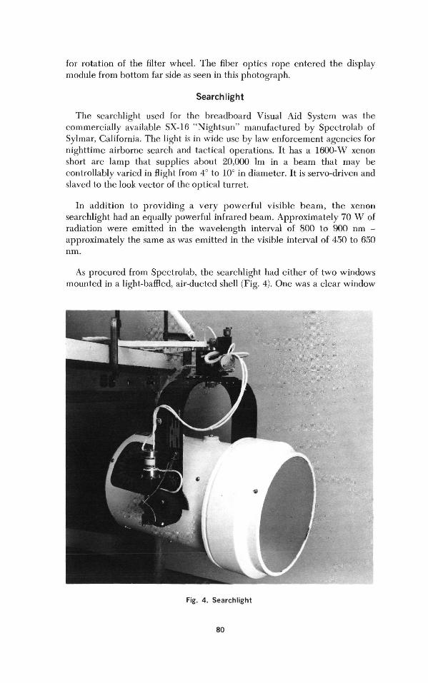
The searchlight used for the breadboard Visual Aid System was thecommercially available SX-16 "Nightsun" manufactured by Spectrolab ofSylmar, California. The light is in wide use by law enforcement agencies fornighttime airborne search and tactical operations. It has a 1600-W xenonshort arc lamp that supplies about 20,000 1m in a beam that may becontrollably varied in flight from 4° to 10° in diameter. It is servo-driven andslaved to the look vector of the optical turret.
In addition to providing a very powerful visible beam, the xenonsearchlight had an equally powerful infrared beam. Approximately 70 W ofradiation were emitted in the wavelength interval of 800 to 900 nm -approximately the same as was emitted in the visible interval of 450 to 650nm.
As procured from Spectrolab, the searchlight had either of two windowsmounted in a light-baffled, air-ducted shell (Fig. 4). One was a clear window
Fig. 4. Searchlight
80
that passed essentially all visible and near-infrared radiation. The other had amultilayer interference filter that passed the near-infrared, but reflectedessentially all visible radiation back to the bulb. The 10% and 90% points onthe transmission curve were 775 and 840 nm, respectively. This transmissioncharacteristic reduced the visibility of the direct searchlight beam to anappearance similar to that of the helicopter running lights when viewedfrom a distance. However, at distances of 1000 ft or so, the large anglesubtended by the searchlight reflector distinguished it from running lights.
Control Console
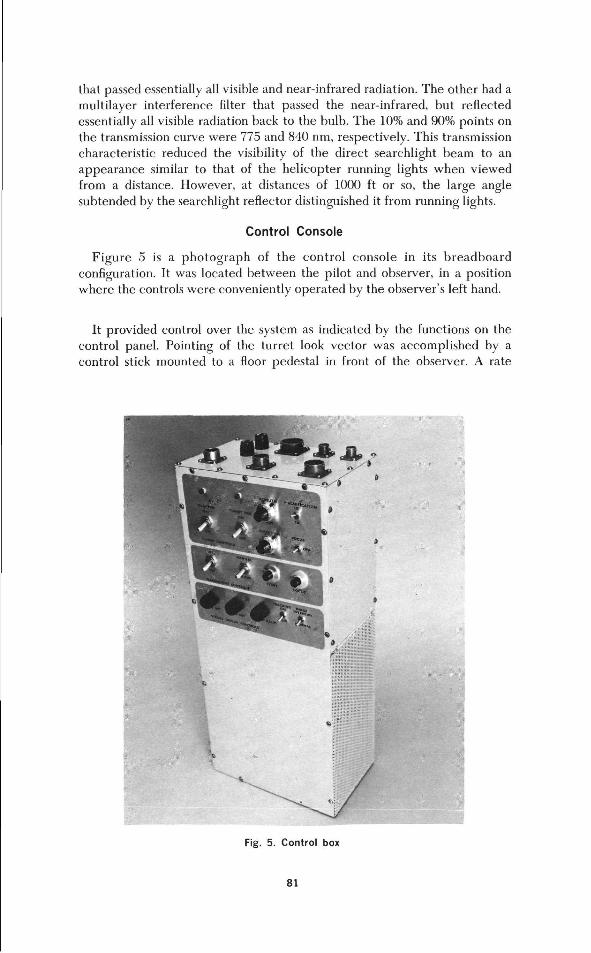
Figure 5 is a photograph of the control console in its breadboardconfiguration. It was located between the pilot and observer, in a positionwhere the controls were conveniently operated by the observer's left hand.
It provided control over the system as indicated by the functions on thecontrol panel. Pointing of the turret look vector was accomplished by acontrol stick mounted to a floor pedestal in front of the observer. A rate
*>&
Fig. 5. Control box
81
MODULE
1
13
isg z
r-j O•1.
U
Q5
ll
UJ U
BZo
rOh
•am~o'coo«ouiUJ
82
control stick mechanization was selected for the human interface with theturret drives, largely because of the results of a previous study that hadshown superior pointing accuracy of an airborne payload by an operatorusing this type of control. The rate stick provided a plus and minus voltageoutput proportional to the force vector applied for each of two orthogonaldirections. The stick had an appearance similar to an aircraft control stick,except that it did not significantly deflect in response to manual controlpressure.
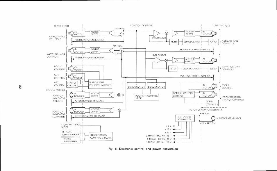
Figure 6 is a functional block diagram illustrating the approach taken forelectronic control and power conversion. The control console is showninside dotted lines in the center of the diagram and the functionalinterconnections with the other modules of the helicopter Visual Aid Systemare shown. Interconnections with the turret module, the searchlight module,the display module, and the generator assembly are shown in sufficient detailto make clear the type of control used for positioning and controlling thevarious parts of the Visual Aid System.
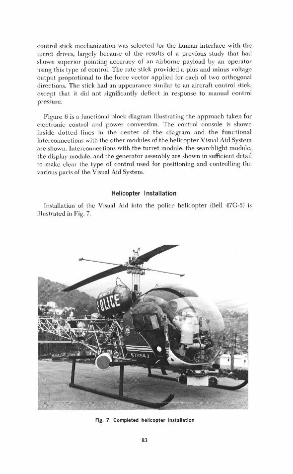
Helicopter Installation
Installation of the Visual Aid into the police helicopter (Bell 47G-5) isillustrated in Fig. 7.
Fig. 7. Completed helicopter installation
83
Test Program
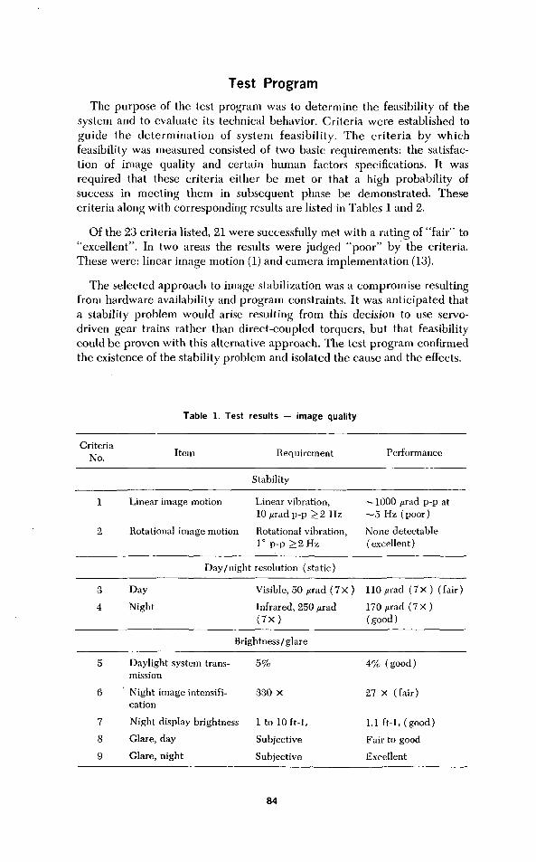
The purpose of the test program was to determine the feasibility of thesystem and to evaluate its technical behavior. Criteria were established toguide the determination of system feasibility. The criteria by whichfeasibility was measured consisted of two basic requirements: the satisfac-tion of image quality and certain human factors specifications. It wasrequired that these criteria either be met or that a high probability ofsuccess in meeting them in subsequent phase be demonstrated. Thesecriteria along with corresponding results are listed in Tables 1 and 2.
Of the 23 criteria listed, 21 were successfully met with a rating of "fair" to"excellent". In two areas the results were judged "poor" by the criteria.These were: linear image motion (1) and camera implementation (13).
The selected approach to image stabilization was a compromise resultingfrom hardware availability and program constraints. It was anticipated thata stability problem would arise resulting from this decision to use servo-driven gear trains rather than direct-coupled torquers, but that feasibilitycould be proven with this alternative approach. The test program confirmedthe existence of the stability problem and isolated the cause and the effects.
Table 1. Test results — image quality
CriteriaNo. Item Requirement Performance
Stability
1 Linear image motion Linear vibration,10/jradp-p >2 Hz
2 Rotational image motion Rotational vibration,1° p-p >2Hz
~1000 /irad p-p at~5 Hz (poor)
None detectable(excellent)
3
4
Day/night
Day
Night
resolution (static)
Visible, 50 ;n rad (7x)
Infrared, 250 /aad( 7 X )
110/irad ( 7 X ) (fair)
170/irad ( 7 X )( good )
Brightness/glare
5
6
7
8
9
Daylight system trans-mission
Night image intensifi-cation
Night display brightness
Glare, day
Glare, night
5%
330 X
1 to 10 ft-L
Subjective
Subjective
4% (good)
27 X (fair)
1.1 ft-L (good)
Fair to good
Excellent
84
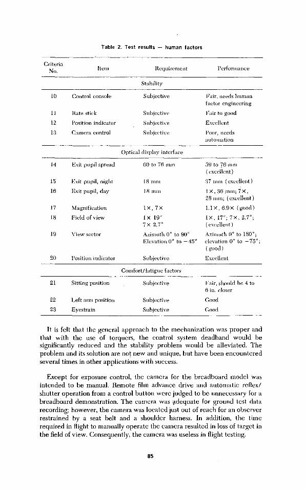
Table 2. Test results — human factors
CriteriaNo. Item Requirement Performance
Stability
10
11
12
13
Control console
Rate stick
Position indicator
Camera control
Subjective
Subjective
Subjective
Subjective
Fair, needs humanfactor engineering
Fair to good
Excellent
Poor, needsautomation
Optical display interface
14
15
16
17
18
19
20
Exit pupil spread
Exit pupil, night
Exit pupil, day
Magnification
Field of view
View sector
Position indicator
60 to 76 mm
18 mm
18 mm
I X , 7 X
IX 19°7X 2.7°
Azimuth 0° to 90°Elevation 0° to -45°
Subjective
59 to 76 mm( excellent )
37 mm ( excellent )
IX, 36 m m ; 7 X ,28mm; (excellent)
1.1X, 6.9X (good)
IX, 17°; 7X, 2.7°;( excellent )
Azimuth 0° to 180°;elevation 0° to -75°;( good )
Excellent
Comfort/fatigue factors
21
22
23
Sitting position
Left arm position
Eyes train
Subjective
Subjective
Subjective
Fair, should be 4 to6 in. closer
Good
Good
It is felt that the general approach to the mechanization was proper andthat with the use of torquers, the control system deadband would besignificantly reduced and the stability problem would be alleviated. Theproblem and its solution are not new and unique, but have been encounteredseveral times in other applications with success.
Except for exposure control, the camera for the breadboard model wasintended to be manual. Remote film advance drive and automatic reflex/shutter operation from a control button were judged to be unnecessary for abreadboard demonstration. The camera was adequate for ground test datarecording; however, the camera was located just out of reach for an observerrestrained by a seat belt and a shoulder harness. In addition, the timerequired in flight to manually operate the camera resulted in loss of target inthe field of view. Consequently, the camera was useless in flight testing.
85
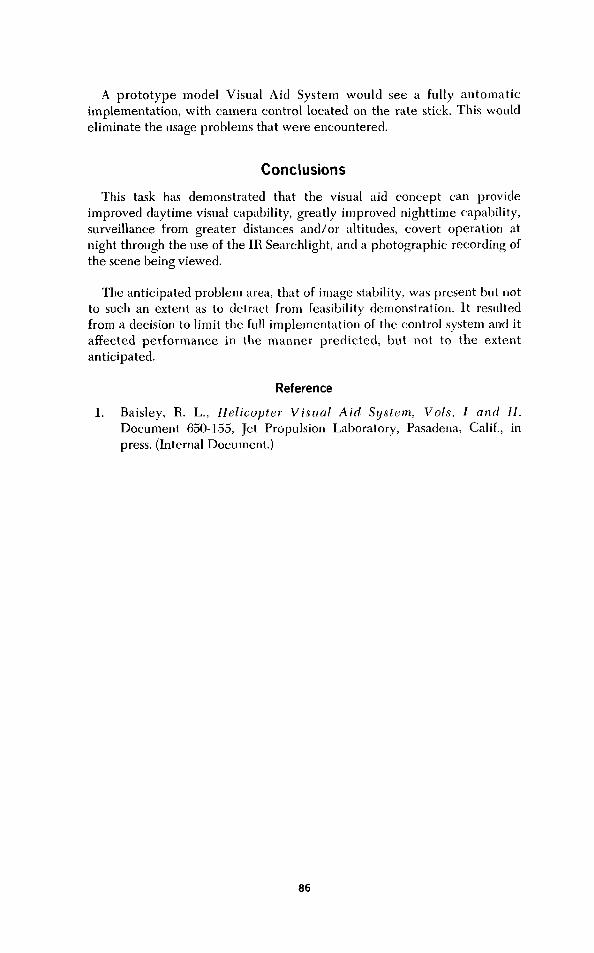
A prototype model Visual Aid System would see a fully automaticimplementation, with camera control located on the rate stick. This wouldeliminate the usage problems that were encountered.
Conclusions
This task has demonstrated that the visual aid concept can provideimproved daytime visual capability, greatly improved nighttime capability,surveillance from greater distances and/or altitudes, covert operation atnight through the use of the IR Searchlight, and a photographic recording ofthe scene being viewed.
The anticipated problem area, that of image stability, was present but notto such an extent as to detract from feasibility demonstration. It resultedfrom a decision to limit the full implementation of the control system and itaffected performance in the manner predicted, but not to the extentanticipated.
Reference
1. Baisley, R. L., Helicopter Visual Aid System, Vols. I and II.Document 650-155, Jet Propulsion Laboratory, Pasadena, Calif., inpress. (Internal Document.)
86