Embed Size (px)
Citation preview
International Journal of Scientific and Research Publications, Volume 2, Issue 4, April 2012 1 ISSN 2250-3153
www.ijsrp.org
A Review of Sub-Carrier Selection Techniques Employed
in MC-CDMA System for 4G Networks
Hema Kale, C.G. Dethe, M.M. Mushrif
Abstract- The Multi-Carrier Code Division Multiple Access
(MC-CDMA) is becoming a very attractive multiple access
technique for high-rate data transmission in the future wireless
communication systems. This paper is focused on reviewing
different sub-carrier selection techniques for MC-CDMA system.
It has been seen that appropriate subcarrier selection
technique can significantly improve BER performance,
Throughput performance, System capacity, Speed and it results
in higher spectrum efficiency as well as reduced power
consumption at mobile terminal.
Broadly it can be implemented either by selecting the best sub-
carrier and transmitting the whole data of the user through that
sub-carrier only or varying the number of sub-carriers allotted
according to users requirement and transmitting user’s data
through the selected group of sub-carriers.
Index Terms- SCS, MC-CDMA, UWB, SNR, BER,
ACA, APA
I. INTRODUCTION
A. 4G systems
Future generations of broadband wireless systems will aim to
support a wide range of services and bit rates in a bandwidth of
the order of tens or even hundreds of megahertz. FCC has
mandated that the UWB radio transmission lies between 3.1 and
10.6 GHz, with a minimum bandwidth of 500 MHz [1]. The
most important objectives in the design of 4G wireless systems
are to address the severe inter symbol interference (ISI) resulting
from the high data rates, and to utilize the available bandwidth in
a spectrally efficient manner. Recently, multicarrier code
division multiple access systems (MC-CDMA) have been
considered as the potential candidate for 4G wireless
communications which handles ISI most effectively [3].
MCCDMA can outperform OFDMA in the case of varying
resource loads. The BER performance of MC-CDMA could be
better than OFDMA, when traffic load is not very high.
Sub-carrier selecting MC-CDMA system is employed in
development of 4G systems to reduce high power consumption
of mobile terminals, to increase cell coverage area and to
minimize the effect of high Doppler frequency which are
otherwise the concerning issues because of the wide bandwidth
transmission needed and the expected use of the high frequency
microwave band [2].
B. MC-CDMA
Fourth generation wireless communication demands a better
multiple access technique for reducing the multiple access
interference (MAI) and intersymbol interference (ISI) and to
improve the bit error rate performance. It is pointed out by
G.K.D. Prasanna venkatesan in [1] that MC-CDMA can prove to
be the best candidate satisfies the demands of 4G wireless
systems.
The conventional code-division multiple-access (CDMA)
technique used in third generation system faces serious
limitations by channel dispersion causing inter symbol
interference (ISI), and it requires advanced signal processing
algorithms to implement it. The MC-CDMA employing multiple
stream of data channel can combat channel dispersion, hence ISI,
thereby increasing system capability to accommodate a higher
number of users and its data rate requirements [4].
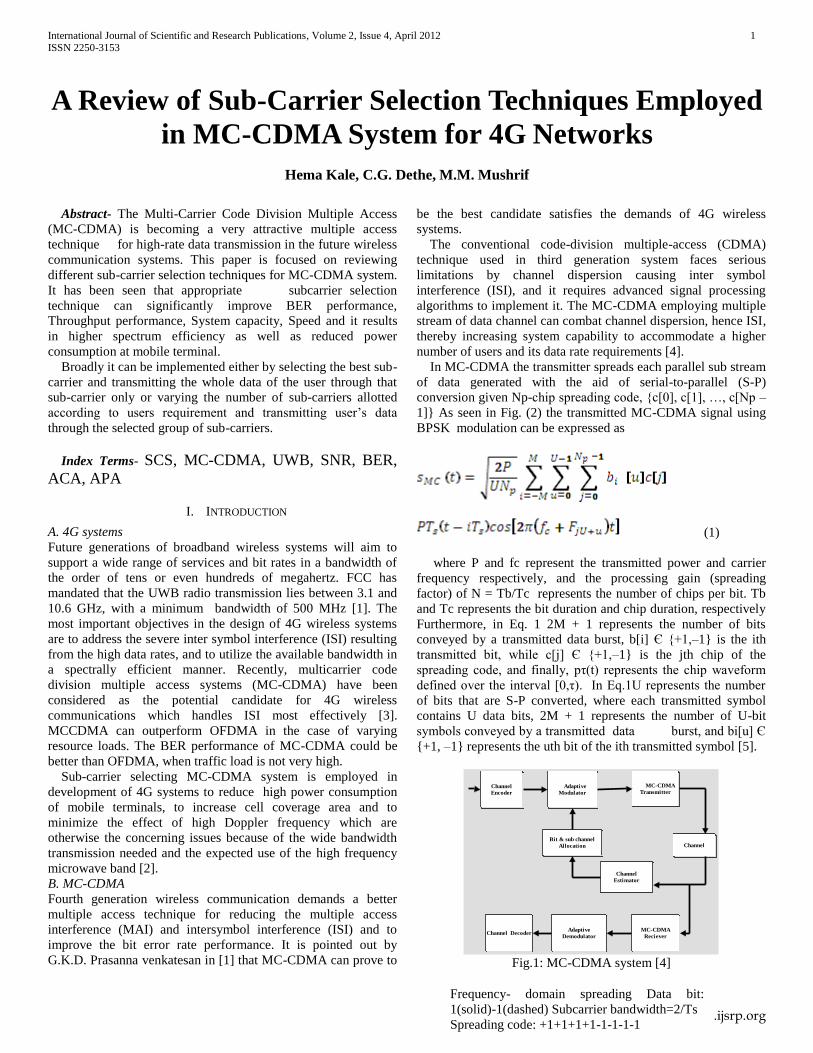
In MC-CDMA the transmitter spreads each parallel sub stream
of data generated with the aid of serial-to-parallel (S-P)
conversion given Np-chip spreading code, {c[0], c[1], …, c[Np –
1]} As seen in Fig. (2) the transmitted MC-CDMA signal using
BPSK modulation can be expressed as
(1)
where P and fc represent the transmitted power and carrier
frequency respectively, and the processing gain (spreading
factor) of N = Tb/Tc represents the number of chips per bit. Tb
and Tc represents the bit duration and chip duration, respectively
Furthermore, in Eq. 1 2M + 1 represents the number of bits
conveyed by a transmitted data burst, b[i] Є {+1,–1} is the ith
transmitted bit, while c[j] Є {+1,–1} is the jth chip of the
spreading code, and finally, pτ(t) represents the chip waveform
defined over the interval [0,τ). In Eq.1U represents the number
of bits that are S-P converted, where each transmitted symbol
contains U data bits, 2M + 1 represents the number of U-bit
symbols conveyed by a transmitted data burst, and bi[u] Є
{+1, –1} represents the uth bit of the ith transmitted symbol [5].
Channel
Encoder
Adaptive
Modulator
MC-CDMA
Transmitter
Channel DecoderAdaptive
Demodulator
MC-CDMA
Reciever
ChannelBit & sub channel
Allocation
Channel
Estimator
Fig.1: MC-CDMA system [4]
Frequency- domain spreading Data bit:
1(solid)-1(dashed) Subcarrier bandwidth=2/Ts
Spreading code: +1+1+1+1-1-1-1-1
International Journal of Scientific and Research Publications, Volume 2, Issue 4, April 2012 2
ISSN 2250-3153
www.ijsrp.org
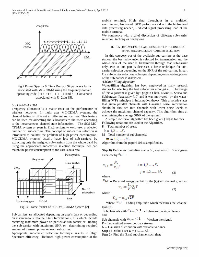
Fig.2 Power Spectra & Time Domain Signal wave forms
associated with MC-CDMA using the frequency domain
spreading code {+1+1+1+1 -1-1-1-1}and S-P Conversion
associated with U=2bits [5].
C. SCS-MC-CDMA
Frequency allocation is a major issue in the performance of
wireless networks. In multi user MC-CDMA systems, the
channel fading is different at different sub carriers. This feature
can be used for allocating the subcarriers to the users according
to the instantaneous channel state information. The SCS-MC-
CDMA system as seen in Fig.3 assigns to each user a selected
number of sub-carriers. The concept of sub-carrier selection is
introduced to counter the problem of high power consumption.
MC-CDMA systems usually have lots of sub-carriers, by
extracting only the assigned sub-carriers from the whole band by
using the appropriate sub-carrier selection technique, we can
match the power consumption to the user’s data rate.
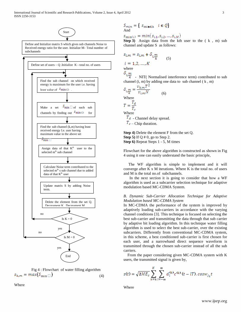
Fig. 3: Frame format of SCS-MC-CDMA system [2]
Sub carriers are allocated depending on user’s data or depending
on instantaneous Channel State Information (CSI) which include
receiving maximum power on particular sub-carrier or finding
the sub-carrier with maximum SNR or determining required
amount of transmit power on each subcarrier.
Appropriate sub-carrier selection technique results in High
Spectrum efficiency, Reduced high power consumption at the
mobile terminal, High data throughput in a multicell
environment, Improved BER performance due to the high-speed
data processing needed, Reduced signal processing load at the
mobile terminal.
We commence with a brief discussion of different sub-carrier
selection techniques one by one.
II. OVERVIEW OF SUB-CARRIER SELECTION TECHNIQUES
EMPLOYING SINGLE SUB-CARRIER SELECTION
In this category out of the available sub-carriers at the base
station the best sub-carrier is selected for transmission and the
whole data of the user is transmitted through that sub-carrier
only. Part A and part B discusses a basic technique for sub-
carrier selection depending on the SNR of the sub-carrier. In part
C a sub-carrier selection technique depending on receiving power
of the sub-carrier is discussed.
A.Water-filling algorithm
Water-filling algorithm has been employed in many research
studies for selecting the best sub-carrier amongst all. The design
of this algorithm is given by Qingxin Chen, Elvino S. Sousa and
Subbarayan Pasupathy [10] and it was motivated by the water-
filling (WF) principle in information theory. This principle states
that given parallel channels with Gaussian noise, information
should be first fed into channels with lower noise levels to
achieve the maximum channel capacity. This algorithm aims at
maximizing the average SINR of the system.
A simple recursive algorithm has been given [10] as follows
Following notations are used in the Algorithm,
K – Total number of users,
M – Total number of subchannels.
Algorithm from the paper [10] is simplified as,
Step 0) Define and initialize matrix S , elements of S are given
as below by :
(2)
where
-- Received energy per bit for the (i,j) sub channel given as,
(3)
where
Where -- Fading amplitude which measures the channel
quality .
Sub channels with - Enhances the signal levels
and
Sub channels with - Weaken the signal.
P – Transmitted Power per data stream.
N -- Gaussian distribution with variable variance
Step 1) Define a set Q = {1,2,...,K}.
Step 2) Find the (k,rn) subchannel such that:
International Journal of Scientific and Research Publications, Volume 2, Issue 4, April 2012 3
ISSN 2250-3153
www.ijsrp.org
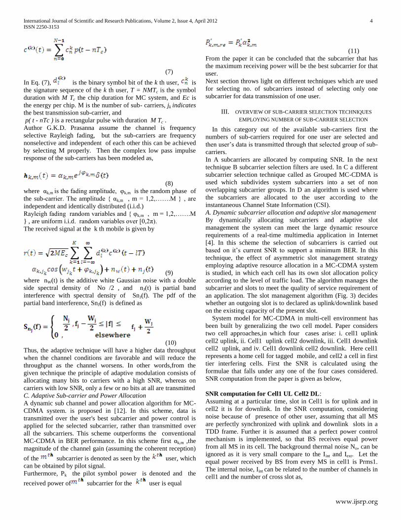
Fig 4 : Flowchart of water filling algorithm
(4)
Where
And
Step 3) Assign data from the kth user to the ( k , m) sub
channel and update S as follows:
(5)
where
- NIT( Normalised interference term) contributed to sub
channel (i, m) by adding one data to sub channel ( k , m)
(6)
Where
Where
- Channel delay spread.
– Chip duration.
Step 4) Delete the element F from the set Q.
Step 5) If Q # 0, go to Step 2.
Step 6) Repeat Steps 1 - 5, M times
Flowchart for the above algorithm is constructed as shown in Fig
4 using it one can easily understand the basic principle,
The WF algorithm is simple to implement and it will
converge after K x M iterations. Where K is the total no. of users
and M is the total no.of subchannels.
In the next section it is going to consider that how a WF
algorithm is used as a subcarrier selection technique for adaptive
modulation based MC-CDMA System.
B. Dynamic Sub-Carrier Allocation Technique for Adaptive
Modulation based MC-CDMA System
In MC-CDMA the performance of the system is improved by
adaptively loading sub-carriers in accordance with the varying
channel conditions [3]. This technique is focused on selecting the
best sub-carrier and transmitting the data through that sub carrier
by adaptive bit loading algorithm. In this technique water filling
algorithm is used to select the best sub-carrier, over the existing
subcarriers. Differently from conventional MC-CDMA system,
in this scheme, a best conditioned sub-carrier is first chosen for
each user, and a narrowband direct sequence waveform is
transmitted through the chosen sub-carrier instead of all the sub
carriers.
From the paper considering given MC-CDMA system with K
users, the transmitted signal is given by,
Where
Define and Initialize matrix S which gives sub channels Noise to
Received energy ratio for the user. Initialize M- Total number of subchannels
Define set of users – Q .Initialize K - total no. of users
Find the sub channel (k,m) having least
received energy I.e. user having maximum value in the above set
Make a set of such sub
channels by finding out for all the users
Assign data of that Kth user to the
selected mth sub channel
Update matrix S by adding Noise
term.
Delete the element from the set Q.
Decreament K , Decreament M
Is K = 0
Calculate Noise term contributed to the selected mth s sub channel due to added
data of that Kth user
Is M = 0
End
Start
no
Find the sub channel on which received
energy is maximum for the user i.e. having
least value of .
yes
yes
no
International Journal of Scientific and Research Publications, Volume 2, Issue 4, April 2012 4
ISSN 2250-3153
www.ijsrp.org
(7)
In Eq. (7), is the binary symbol bit of the k th user, is
the signature sequence of the k th user, T = NMTc is the symbol
duration with M Tc the chip duration for MC system, and Ec is
the energy per chip. M is the number of sub- carriers, jk indicates
the best transmission sub-carrier, and
p( t - nTc ) is a rectangular pulse with duration M Tc .
Author G.K.D. Prasanna assume the channel is frequency
selective Rayleigh fading, but the sub-carriers are frequency
nonselective and independent of each other this can be achieved
by selecting M properly. Then the complex low pass impulse
response of the sub-carriers has been modeled as,
(8)
where αk,m is the fading amplitude, φk,m is the random phase of
the sub-carrier. The amplitude { αk,m , m = 1,2,…….M } , are
independent and identically distributed (i.i.d.)
Rayleigh fading random variables and { φk,m , m = 1,2,…….M
} , are uniform i.i.d. random variables over [0,2π).
The received signal at the k th mobile is given by
(9)
where nW(t) is the additive white Gaussian noise with a double
side spectral density of No /2 , and nJ(t) is partial band
interference with spectral density of SnJ(f). The pdf of the
partial band interference, SnJ(f) is defined as
(10)
Thus, the adaptive technique will have a higher data throughput
when the channel conditions are favorable and will reduce the
throughput as the channel worsens. In other words,from the
given technique the principle of adaptive modulation consists of
allocating many bits to carriers with a high SNR, whereas on
carriers with low SNR, only a few or no bits at all are transmitted
C. Adaptive Sub-carrier and Power Allocation
A dynamic sub channel and power allocation algorithm for MC-
CDMA system. is proposed in [12]. In this scheme, data is
transmitted over the user's best subcarrier and power control is
applied for the selected subcarrier, rather than transmitted over
all the subcarriers. This scheme outperforms the conventional
MC-CDMA in BER performance. In this scheme first αk,m ,the
magnitude of the channel gain (assuming the coherent reception)
of the subcarrier is denoted as seen by the user, which
can be obtained by pilot signal.
Furthermore, Pk the pilot symbol power is denoted and the
received power of subcarrier for the user is equal
(11)
From the paper it can be concluded that the subcarrier that has
the maximum receiving power will be the best subcarrier for that
user.
Next section throws light on different techniques which are used
for selecting no. of subcarriers instead of selecting only one
subcarrier for data transmission of one user.
III. OVERVIEW OF SUB-CARRIER SELECTION TECHNIQUES
EMPLOYING NUMBER OF SUB-CARRIER SELECTION
In this category out of the available sub-carriers first the
numbers of sub-carriers required for one user are selected and
then user’s data is transmitted through that selected group of sub-
carriers.
In A subcarriers are allocated by computing SNR. In the next
technique B subcarrier selection filters are used. In C a different
subcarrier selection technique called as Grouped MC-CDMA is
used which subdivides system subcarriers into a set of non
overlapping subcarrier groups. In D an algorithm is used where
the subcarriers are allocated to the user according to the
instantaneous Channel State Information (CSI).
A. Dynamic subcarrier allocation and adaptive slot management
By dynamically allocating subcarriers and adaptive slot
management the system can meet the large dynamic resource
requirements of a real-time multimedia application in Internet
[4]. In this scheme the selection of subcarriers is carried out
based on it’s current SNR to support a minimum BER. In this
technique, the effect of asymmetric slot management strategy
employing adaptive resource allocation in a MC-CDMA system
is studied, in which each cell has its own slot allocation policy
according to the level of traffic load. The algorithm manages the
subcarrier and slots to meet the quality of service requirement of
an application. The slot management algorithm (Fig. 3) decides
whether an outgoing slot is to declared as uplink/downlink based
on the existing capacity of the present slot.
System model for MC-CDMA in multi-cell environment has
been built by generalizing the two cell model. Paper considers
two cell approaches,in which four cases arise: i. cell1 uplink
cell2 uplink, ii. Cell1 uplink cell2 downlink, iii. Cell1 downlink
cell2 uplink, and iv. Cell1 downlink cell2 downlink. Here cell1
represents a home cell for tagged mobile, and cell2 a cell in first
tier interfering cells. First the SNR is calculated using the
formulae that falls under any one of the four cases considered.
SNR computation from the paper is given as below,
SNR computation for Cell1 UL Cell2 DL:
Assuming at a particular time, slot in Cell1 is for uplink and in
cell2 it is for downlink. In the SNR computation, considering
noise because of presence of other user, assuming that all MS
are perfectly synchronized with uplink and downlink slots in a
TDD frame. Further it is assumed that a perfect power control
mechanism is implemented, so that BS receives equal power
from all MS in its cell. The background thermal noise No, can be
ignored as it is very small compare to the Iint and Iext. Let the
equal power received by BS from every MS in cell1 is Prms1.
The internal noise, Iint can be related to the number of channels in
cell1 and the number of cross slot as,
International Journal of Scientific and Research Publications, Volume 2, Issue 4, April 2012 5
ISSN 2250-3153
www.ijsrp.org
Fig.5 : Flow chart of algorithm [4]
Iint = {(m1 / No ) – 1} Prms1 (12)
The external noise Iext in cell1 is the downlink signal
originating from BS in cell2, and can be given by,
(13)
Where 2D is the distance (i.e. cell radius of D) between two BS,
Ptbs2 is the transmit power at BS2. If W is the total spreading
bandwidth, the spreading factor, (also called processing gain) for
uplink, SFu is given by,
(14)
Now the SNR for the uplink slot in cell1 is given by
(15)
BER Calculation
The BER for the Ith Sub-Carrier corresponding to M-QAM is
given by [16]
(16)
Where SNRi is the signal to noise ratio for Ith subcarrier, and
M is the constellation points in M-QAM
The SNR is recomputed every time based on the new call arrival
rate, and hence the addition of a new subcarrier in a slot. The
new call includes handoff user too. The BER is computed using
(16) based on the SNR and a high modulation order (M=8). If
BER > 10-3
, then order of modulation M is reduced and BER is
computed again, and this process is repeated till BER falls below
10-3
and the corresponding M value is retained to be used for
order of modulation in M-QAM. If BER does not falls below10-3
and M = 2, then the next slot is declared as same status (e.g.
uplink if the current slot is uplink) and new calls are
accommodated in new slots. Based on the existing SNR and
application’s bandwidth requirement, the no. of subcarriers are
allocated to these new calls. If the accumulated bandwidth
(BWc) i.e. no of subcarrier is just enough to meet the
requirement (BWr), the resource allocation completes for a user
and the algorithm takes next call to be processed.
In the next technique Butterworth filter is used for subcarrier
selection.
B. Sub-Carrier Selecting MC-CDMA System for 4G Systems
Teruya Fujii, Noboru Izuka, Hiroyoshi Masui, and Atsushi
Nagate [2] has introduced the concept of sub-carrier selection to
counter the problem of high power consumption. For high speed
data processing high power consumption at the mobile terminals
is needed. In this scheme each user has assigned only as many
subcarriers as are needed to support the user’s data rate. To
reduce the implementation complexity here in the paper,use of
only one or two sub-carrier selection filters is considered.
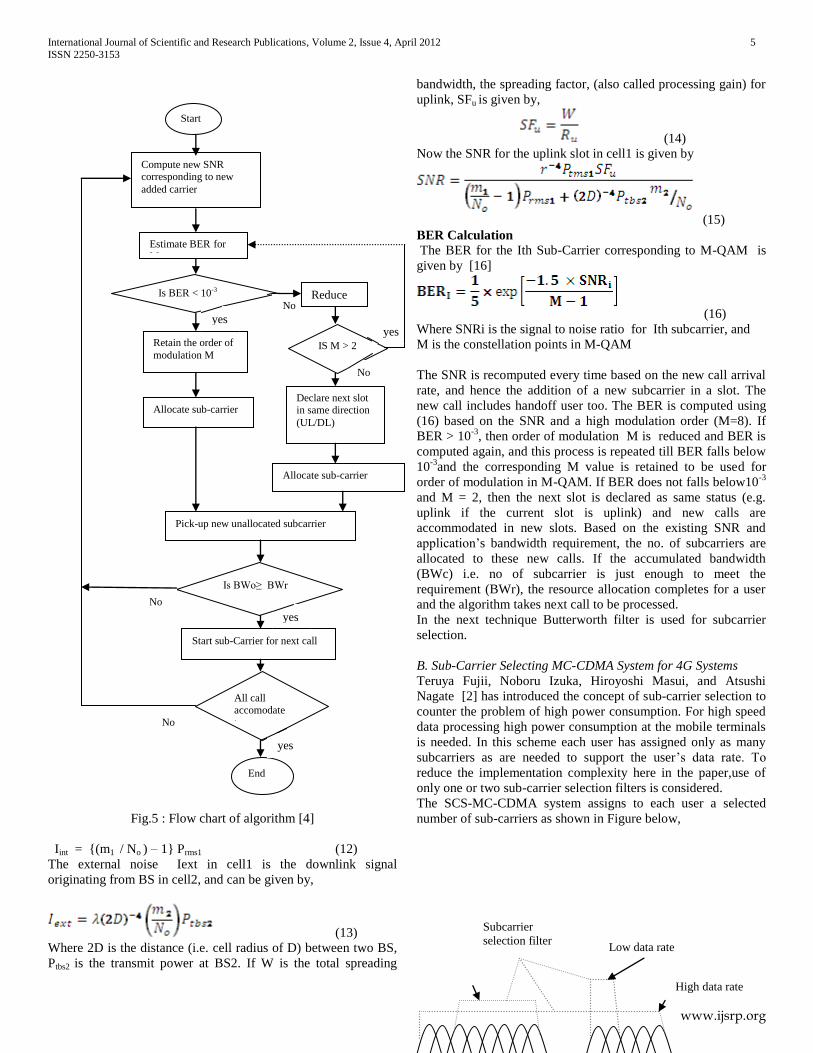
The SCS-MC-CDMA system assigns to each user a selected
number of sub-carriers as shown in Figure below,
Compute new SNR corresponding to new
added carrier
Estimate BER for M
Is BER < 10-3
Retain the order of
modulation M
Allocate sub-carrier
Pick-up new unallocated subcarrier
Reduce
M
IS M > 2
Declare next slot in same direction
(UL/DL)
Allocate sub-carrier
Is BWo≥ BWr
Start sub-Carrier for next call
All call accomodate te
End
Start
yes
No
yes
No
No
No
yes
yes
High data rate
Low data rate
Subcarrier
selection filter
International Journal of Scientific and Research Publications, Volume 2, Issue 4, April 2012 6
ISSN 2250-3153
www.ijsrp.org
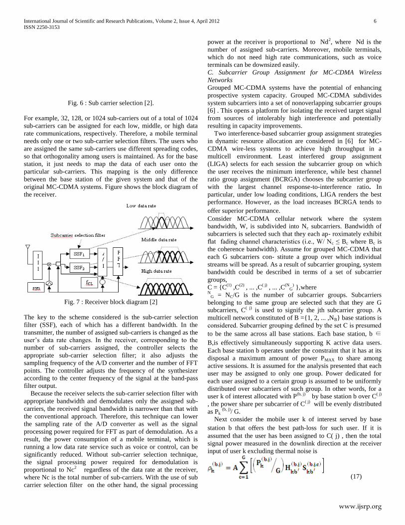
Fig. 6 : Sub carrier selection [2].
For example, 32, 128, or 1024 sub-carriers out of a total of 1024
sub-carriers can be assigned for each low, middle, or high data
rate communications, respectively. Therefore, a mobile terminal
needs only one or two sub-carrier selection filters. The users who
are assigned the same sub-carriers use different spreading codes,
so that orthogonality among users is maintained. As for the base
station, it just needs to map the data of each user onto the
particular sub-carriers. This mapping is the only difference
between the base station of the given system and that of the
original MC-CDMA systems. Figure shows the block diagram of
the receiver.
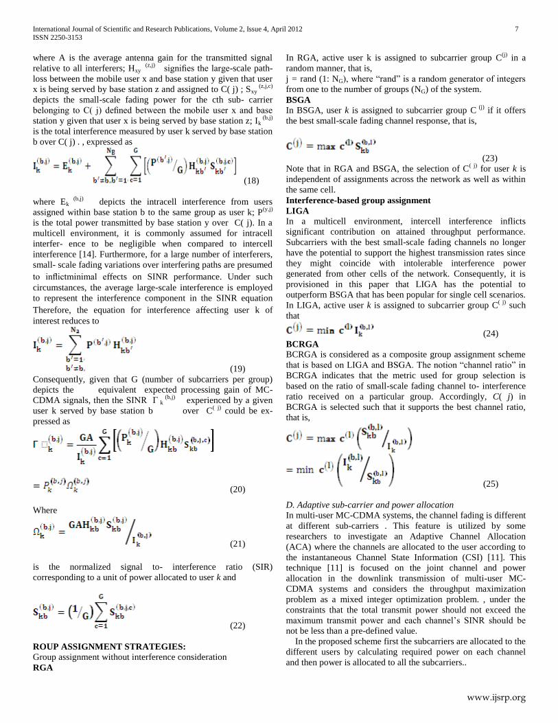
Fig. 7 : Receiver block diagram [2]
The key to the scheme considered is the sub-carrier selection
filter (SSF), each of which has a different bandwidth. In the
transmitter, the number of assigned sub-carriers is changed as the
user’s data rate changes. In the receiver, corresponding to the
number of sub-carriers assigned, the controller selects the
appropriate sub-carrier selection filter; it also adjusts the
sampling frequency of the A/D converter and the number of FFT
points. The controller adjusts the frequency of the synthesizer
according to the center frequency of the signal at the band-pass
filter output.
Because the receiver selects the sub-carrier selection filter with
appropriate bandwidth and demodulates only the assigned sub-
carriers, the received signal bandwidth is narrower than that with
the conventional approach. Therefore, this technique can lower
the sampling rate of the A/D converter as well as the signal
processing power required for FFT as part of demodulation. As a
result, the power consumption of a mobile terminal, which is
running a low data rate service such as voice or control, can be
significantly reduced. Without sub-carrier selection technique,
the signal processing power required for demodulation is
proportional to Nc2
regardless of the data rate at the receiver,
where Nc is the total number of sub-carriers. With the use of sub
carrier selection filter on the other hand, the signal processing
power at the receiver is proportional to Nd2, where Nd is the
number of assigned sub-carriers. Moreover, mobile terminals,
which do not need high rate communications, such as voice
terminals can be downsized easily.
C. Subcarrier Group Assignment for MC-CDMA Wireless
Networks
Grouped MC-CDMA systems have the potential of enhancing
prospective system capacity. Grouped MC-CDMA subdivides
system subcarriers into a set of nonoverlapping subcarrier groups
[6] . This opens a platform for isolating the received target signal
from sources of intolerably high interference and potentially
resulting in capacity improvements.
Two interference-based subcarrier group assignment strategies
in dynamic resource allocation are considered in [6] for MC-
CDMA wire-less systems to achieve high throughput in a
multicell environment. Least interfered group assignment
(LIGA) selects for each session the subcarrier group on which
the user receives the minimum interference, while best channel
ratio group assignment (BCRGA) chooses the subcarrier group
with the largest channel response-to-interference ratio. In
particular, under low loading conditions, LIGA renders the best
performance. However, as the load increases BCRGA tends to
offer superior performance.
Consider MC-CDMA cellular network where the system
bandwidth, W, is subdivided into Nc subcarriers. Bandwidth of
subcarriers is selected such that they each ap- roximately exhibit
flat fading channel characteristics (i.e., W/ Nc ≤ Bc where Bc is
the coherence bandwidth). Assume for grouped MC-CDMA that
each G subcarriers con- stitute a group over which individual
streams will be spread. As a result of subcarrier grouping, system
bandwidth could be described in terms of a set of subcarrier
groups,
C = {C(1)
,C(2)
, ... ,C( j)
, ... ,C(N
G) },where
NG = NC/G is the number of subcarrier groups. Subcarriers
belonging to the same group are selected such that they are G
subcarriers, C( j)
is used to signify the jth subcarrier group. A
multicell network constituted of B ={1, 2, ... ,NB} base stations is
considered. Subcarrier grouping defined by the set C is presumed
to be the same across all base stations. Each base station, b ∈
B,is effectively simultaneously supporting K active data users.
Each base station b operates under the constraint that it has at its
disposal a maximum amount of power PMAX to share among
active sessions. It is assumed for the analysis presented that each
user may be assigned to only one group. Power dedicated for
each user assigned to a certain group is assumed to be uniformly
distributed over subcarriers of such group. In other words, for a
user k of interest allocated with P(b, j)
by base station b over C( j)
, the power share per subcarrier of C( j)
will be evenly distributed
as Pk (b, j)
/ G.
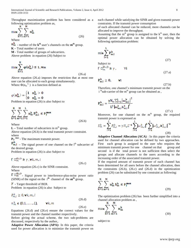
Next consider the mobile user k of interest served by base
station b that offers the best path-loss for such user. If it is
assumed that the user has been assigned to C( j) , then the total
signal power measured in the downlink direction at the receiver
input of user k excluding thermal noise is
(17)
International Journal of Scientific and Research Publications, Volume 2, Issue 4, April 2012 7
ISSN 2250-3153
www.ijsrp.org
where A is the average antenna gain for the transmitted signal
relative to all interferers; Hxy (z,j)
signifies the large-scale path-
loss between the mobile user x and base station y given that user
x is being served by base station z and assigned to C( j) ; Sxy (z,j,c)
depicts the small-scale fading power for the cth sub- carrier
belonging to C( j) defined between the mobile user x and base
station y given that user x is being served by base station z; Ik (b,j)
is the total interference measured by user k served by base station
b over C( j) . , expressed as
(18)
where Ek (b,j)
depicts the intracell interference from users
assigned within base station b to the same group as user k; P(y,j)
is the total power transmitted by base station y over C( j). In a
multicell environment, it is commonly assumed for intracell
interfer- ence to be negligible when compared to intercell
interference [14]. Furthermore, for a large number of interferers,
small- scale fading variations over interfering paths are presumed
to inflictminimal effects on SINR performance. Under such
circumstances, the average large-scale interference is employed
to represent the interference component in the SINR equation
Therefore, the equation for interference affecting user k of
interest reduces to
(19)
Consequently, given that G (number of subcarriers per group)
depicts the equivalent expected processing gain of MC-
CDMA signals, then the SINR Γ k (b,j)
experienced by a given
user k served by base station b over C( j)
could be ex-
pressed as
(20)
Where
(21) is the normalized signal to- interference ratio (SIR)
corresponding to a unit of power allocated to user k and
(22)
ROUP ASSIGNMENT STRATEGIES:
Group assignment without interference consideration
RGA
In RGA, active user k is assigned to subcarrier group C(j)
in a
random manner, that is,
j = rand (1: NG), where “rand” is a random generator of integers
from one to the number of groups (NG) of the system.
BSGA
In BSGA, user k is assigned to subcarrier group C (j)
if it offers
the best small-scale fading channel response, that is,
(23)
Note that in RGA and BSGA, the selection of C( j)
for user k is
independent of assignments across the network as well as within
the same cell.
Interference-based group assignment
LIGA
In a multicell environment, intercell interference inflicts
significant contribution on attained throughput performance.
Subcarriers with the best small-scale fading channels no longer
have the potential to support the highest transmission rates since
they might coincide with intolerable interference power
generated from other cells of the network. Consequently, it is
provisioned in this paper that LIGA has the potential to
outperform BSGA that has been popular for single cell scenarios.
In LIGA, active user k is assigned to subcarrier group C( j)
such
that
(24)
BCRGA
BCRGA is considered as a composite group assignment scheme
that is based on LIGA and BSGA. The notion “channel ratio” in
BCRGA indicates that the metric used for group selection is
based on the ratio of small-scale fading channel to- interference
ratio received on a particular group. Accordingly, C( j) in
BCRGA is selected such that it supports the best channel ratio,
that is,
(25)
D. Adaptive sub-carrier and power allocation
In multi-user MC-CDMA systems, the channel fading is different
at different sub-carriers . This feature is utilized by some
researchers to investigate an Adaptive Channel Allocation
(ACA) where the channels are allocated to the user according to
the instantaneous Channel State Information (CSI) [11]. This
technique [11] is focused on the joint channel and power
allocation in the downlink transmission of multi-user MC-
CDMA systems and considers the throughput maximization
problem as a mixed integer optimization problem. , under the
constraints that the total transmit power should not exceed the
maximum transmit power and each channel’s SINR should be
not be less than a pre-defined value.
In the proposed scheme first the subcarriers are allocated to the
different users by calculating required power on each channel
and then power is allocated to all the subcarriers..
International Journal of Scientific and Research Publications, Volume 2, Issue 4, April 2012 8
ISSN 2250-3153
www.ijsrp.org
Throughput maximization problem has been considered as a
following optimization problem as,
(26)
Where
- number of the kth
user’s channels on the mth
group.
K – Total number of users
M - Total number of groups of subcarriers.
Above problem in equation (26) Subject to
(26.a)
Above equation (26.a) imposes the restriction that at most one
user can be allocated to each group simultaneously.
Where Ф(nm k
) is a function defined as
Problem in equation (26) is also Subject to
(26.b)
Where
L – Total number of subcarriers in mth
group.
Above equation (26.b) is the total transmit power constraint.
where
PT max
- The maximum transmit power.
– The signal power of one channel on the lth
subcarrier of
the desired group.
Problem in equation (26) is also Subject to
(26.c)
Above equation (26.c) is the SINR constraint.
Where
- Signal power to interference-plus-noise power ratio
(SINR) of the signal on the ith
channel of the mth
group.
- Target threshold of BER.
Problem in equation (26) is also Subject to
(26.d)
(26.e)
Equations (26.d) and (26.e) ensure the correct values for the
transmit power and the channel number respectively.
Before giving the actual scheme, the two sub-problems are
discussed, respectively by the author,.
Adaptive Power Allocation (APA): In this paper, the criteria
used for power allocation is to minimize the transmit power on
each channel while satisfying the SINR and given transmit power
constraints. If the transmit power consumption
of each allocated channel can be reduced, more channels can be
allocated to improve the throughput.
Assuming that the mth
group is assigned to the kth
user, then the
optimal power allocation can be obtained by solving the
following optimization problem:
(27)
Subject to
(27.a)
(27.b)
Therefore, one channel’s minimum transmit power on the
i th
sub-carrier of the mth
group can be obtained as ,
(27.c)
Moreover, for one channel on the mth
group, the required
transmit power is expressed as
(28)
Adaptive Channel Allocation (ACA) : In this paper the criteria
used for channel allocation can be defined by two approaches.
First each group is assigned to the user who requires the
minimum transmit power for one channel on that group and
second is if the total power is not sufficient then select the
groups and allocate channels to the users according to the
increasing order of the associated transmit power.
If the required amount of transmit power of each channel has
been determined for all users before the channel allocation, then
the constraints (26.b), (26.c) and (26.d) in the optimization
problem (26) can be substituted by one constraint as following:
(29)
The optimization problem (26) has been further simplified into a
channel allocation problem as ,
(30)
subject to
International Journal of Scientific and Research Publications, Volume 2, Issue 4, April 2012 9
ISSN 2250-3153
www.ijsrp.org
(30.a)
(30.b)
(30.c)
Denoting µm as the user whose transmit power for one channel
on the mth group is minimum among all users, i.e.
(31)
Thus following Proposition 1 is given in the paper,.
Proposition 1. There exists one optimal solution to the
optimization problem (24) satisfying that each group is assigned
to the user who requires the minimum transmit power for one
channel on that group, i.e., for m = 1, . . . , M, the mth
group is
allocated to the µ mth
user.
The size of solution space of the optimization problem (30) is
KM
(L+1)M
, an efficient search method given in proposition 1 can
reduce the size of solution space to (L+1)M
.
According to Proposition 1, each group is associated with a
transmit power, i.e., for m = 1, . . . , M, the associated transmit
power of the mth
group is . If these associated transmit
power for all groups is sorted according to the increasing order,
one can obtain an order
{v(i)}i =1,...,,M, where v(i) is the group whose associated transmit
power is the ith
minimum among the associated transmit power of
all groups..The associated transmit power according to the
increasing order is
(32)
Then, the following Proposition 2. is given in the paper,.
Proposition 2. Under the constraints of any given maximum
transmit power PTmax
and the maximum channel number on every
group L, if the transmit power is not enough to be allocated to all
channels of all groups simultaneously, that is
(33)
then the throughput is maximized by selecting the groups and
allocating channels according to the increasing order of the
associated transmit power, i.e., one optimal channel allocation
for the optimization problem (30) owns the following form
α β
where and
(34)
In this method, the channel with lower transmit power
requirement owns higher priority to be selected for transmission.
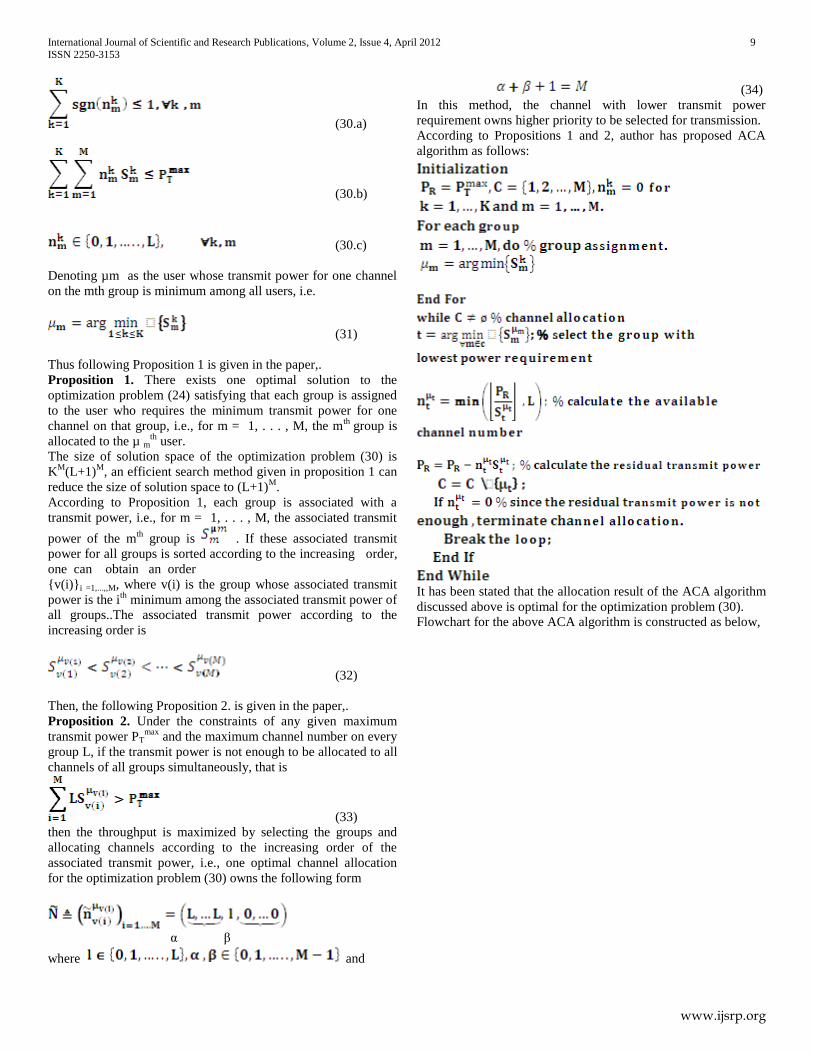
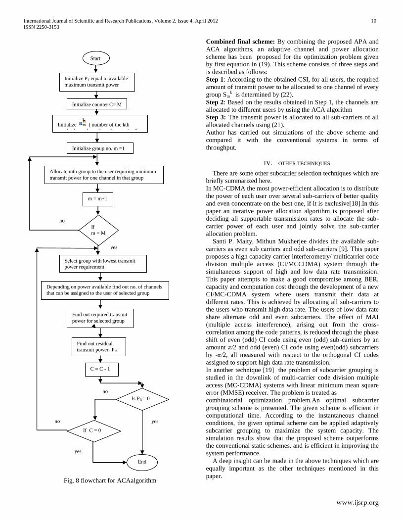
According to Propositions 1 and 2, author has proposed ACA
algorithm as follows:
It has been stated that the allocation result of the ACA algorithm
discussed above is optimal for the optimization problem (30).
Flowchart for the above ACA algorithm is constructed as below,
International Journal of Scientific and Research Publications, Volume 2, Issue 4, April 2012 10
ISSN 2250-3153
www.ijsrp.org
Fig. 8 flowchart for ACAalgorithm
Combined final scheme: By combining the proposed APA and
ACA algorithms, an adaptive channel and power allocation
scheme has been proposed for the optimization problem given
by first equation in (19). This scheme consists of three steps and
is described as follows:
Step 1: According to the obtained CSI, for all users, the required
amount of transmit power to be allocated to one channel of every
group Smk
is determined by (22).
Step 2: Based on the results obtained in Step 1, the channels are
allocated to different users by using the ACA algorithm
Step 3: The transmit power is allocated to all sub-carriers of all
allocated channels using (21).
Author has carried out simulations of the above scheme and
compared it with the conventional systems in terms of
throughput.
IV. OTHER TECHNIQUES
There are some other subcarrier selection techniques which are
briefly summarized here.
In MC-CDMA the most power-efficient allocation is to distribute
the power of each user over several sub-carriers of better quality
and even concentrate on the best one, if it is exclusive[18].In this
paper an iterative power allocation algorithm is proposed after
deciding all supportable transmission rates to allocate the sub-
carrier power of each user and jointly solve the sub-carrier
allocation problem.
Santi P. Maity, Mithun Mukherjee divides the available sub-
carriers as even sub carriers and odd sub-carriers [9]. This paper
proposes a high capacity carrier interferometry/ multicarrier code
division multiple access (CI/MCCDMA) system through the
simultaneous support of high and low data rate transmission.
This paper attempts to make a good compromise among BER,
capacity and computation cost through the development of a new
CI/MC-CDMA system where users transmit their data at
different rates. This is achieved by allocating all sub-carriers to
the users who transmit high data rate. The users of low data rate
share alternate odd and even subcarriers. The effect of MAI
(multiple access interference), arising out from the cross-
correlation among the code patterns, is reduced through the phase
shift of even (odd) CI code using even (odd) sub-carriers by an
amount π/2 and odd (even) CI code using even(odd) subcarriers
by -π/2, all measured with respect to the orthogonal CI codes
assigned to support high data rate transmission.
In another technique [19] the problem of subcarrier grouping is
studied in the downlink of multi-carrier code division multiple
access (MC-CDMA) systems with linear minimum mean square
error (MMSE) receiver. The problem is treated as
combinatorial optimization problem.An optimal subcarrier
grouping scheme is presented. The given scheme is efficient in
computational time. According to the instantaneous channel
conditions, the given optimal scheme can be applied adaptively
subcarrier grouping to maximize the system capacity. The
simulation results show that the proposed scheme outperforms
the conventional static schemes. and is efficient in improving the
system performance.
A deep insight can be made in the above techniques which are
equally important as the other techniques mentioned in this
paper.
Start
Initialize PT equal to available
maximum transmit power
Initialize counter C= M
Initialize ( number of the kth
user’s channels on the mth group) = 0
Initialize group no. m =1
Allocate mth group to the user requiring minimum
transmit power for one channel in that group
m = m+1
If
m = M
Select group with lowest transmit power requirement
Depending on power available find out no. of channels
that can be assigned to the user of selected group
Find out required transmit
power for selected group
Find out residual
transmit power- PR
C = C - 1
Is PR = 0
If C = 0
End
no
yes no
yes
no
yes
International Journal of Scientific and Research Publications, Volume 2, Issue 4, April 2012 11
ISSN 2250-3153
www.ijsrp.org
Table I. Different approaches studied in the paper
V. PERFORMANCE COMPARISON
Simulation results of different techniques are discussed below
with respect to BER performance or throughput performance.
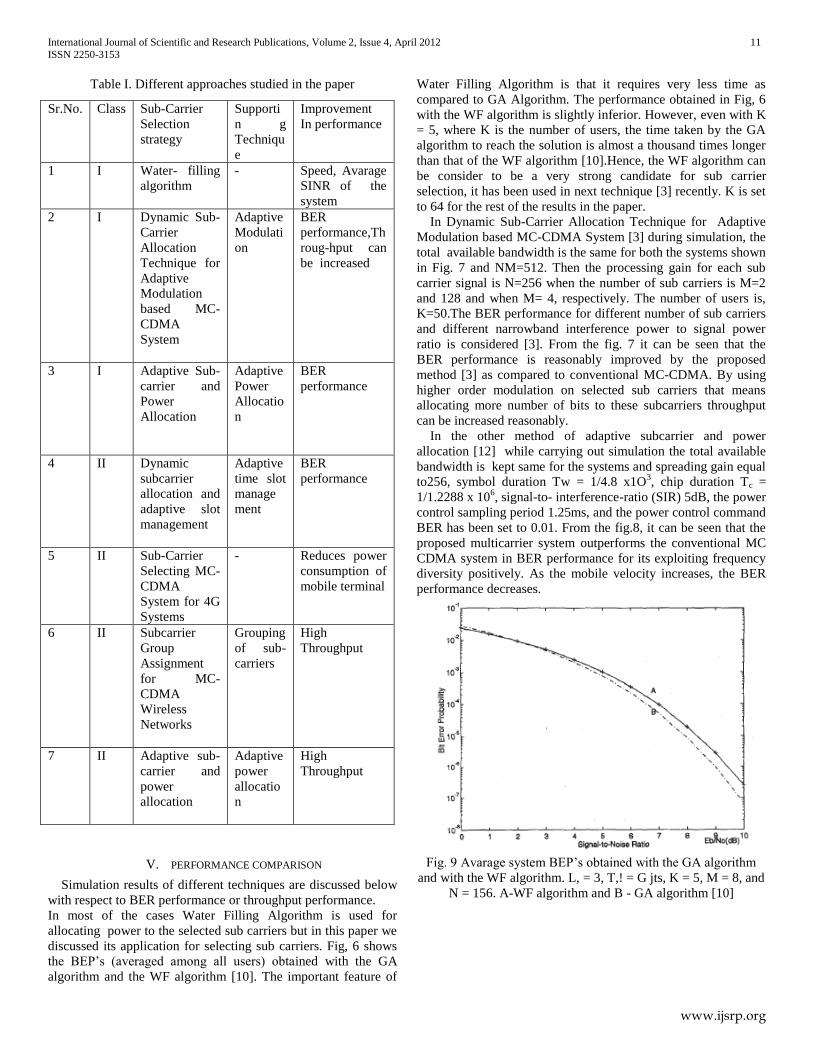
In most of the cases Water Filling Algorithm is used for
allocating power to the selected sub carriers but in this paper we
discussed its application for selecting sub carriers. Fig, 6 shows
the BEP’s (averaged among all users) obtained with the GA
algorithm and the WF algorithm [10]. The important feature of
Water Filling Algorithm is that it requires very less time as
compared to GA Algorithm. The performance obtained in Fig, 6
with the WF algorithm is slightly inferior. However, even with K
= 5, where K is the number of users, the time taken by the GA
algorithm to reach the solution is almost a thousand times longer
than that of the WF algorithm [10].Hence, the WF algorithm can
be consider to be a very strong candidate for sub carrier
selection, it has been used in next technique [3] recently. K is set
to 64 for the rest of the results in the paper.
In Dynamic Sub-Carrier Allocation Technique for Adaptive
Modulation based MC-CDMA System [3] during simulation, the
total available bandwidth is the same for both the systems shown
in Fig. 7 and NM=512. Then the processing gain for each sub
carrier signal is N=256 when the number of sub carriers is M=2
and 128 and when M= 4, respectively. The number of users is,
K=50.The BER performance for different number of sub carriers
and different narrowband interference power to signal power
ratio is considered [3]. From the fig. 7 it can be seen that the
BER performance is reasonably improved by the proposed
method [3] as compared to conventional MC-CDMA. By using
higher order modulation on selected sub carriers that means
allocating more number of bits to these subcarriers throughput
can be increased reasonably.
In the other method of adaptive subcarrier and power
allocation [12] while carrying out simulation the total available
bandwidth is kept same for the systems and spreading gain equal
to256, symbol duration Tw = 1/4.8 x1O3, chip duration Tc =
1/1.2288 x 106, signal-to- interference-ratio (SIR) 5dB, the power
control sampling period 1.25ms, and the power control command
BER has been set to 0.01. From the fig.8, it can be seen that the
proposed multicarrier system outperforms the conventional MC
CDMA system in BER performance for its exploiting frequency
diversity positively. As the mobile velocity increases, the BER
performance decreases.
Fig. 9 Avarage system BEP’s obtained with the GA algorithm
and with the WF algorithm. L, = 3, T,! = G jts, K = 5, M = 8, and
N = 156. A-WF algorithm and B - GA algorithm [10]
Sr.No. Class Sub-Carrier
Selection
strategy
Supporti
n g
Techniqu
e
Improvement
In performance
1 I Water- filling
algorithm
- Speed, Avarage
SINR of the
system
2 I Dynamic Sub-
Carrier
Allocation
Technique for
Adaptive
Modulation
based MC-
CDMA
System
Adaptive
Modulati
on
BER
performance,Th
roug-hput can
be increased
3 I Adaptive Sub-
carrier and
Power
Allocation
Adaptive
Power
Allocatio
n
BER
performance
4 II Dynamic
subcarrier
allocation and
adaptive slot
management
Adaptive
time slot
manage
ment
BER
performance
5 II Sub-Carrier
Selecting MC-
CDMA
System for 4G
Systems
- Reduces power
consumption of
mobile terminal
6 II Subcarrier
Group
Assignment
for MC-
CDMA
Wireless
Networks
Grouping
of sub-
carriers
High
Throughput
7 II Adaptive sub-
carrier and
power
allocation
Adaptive
power
allocatio
n
High
Throughput
International Journal of Scientific and Research Publications, Volume 2, Issue 4, April 2012 12
ISSN 2250-3153
www.ijsrp.org
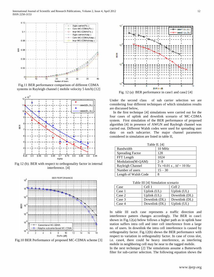
Fig.11 BER performance comparison of different CDMA
systems in Rayleigh channel ( mobile velocity 5 km/h) [12]
Fig 12 (b). BER with respect to orthogonality factor in internal
interference. [4]
Fig.10 BER Performance of proposed MC-CDMA scheme [3]
Fig. 12 (a) BER performance in case1 and case2 [4]
Under the second class of sub carrier selection we are
considering four different techniques of which simulation results
are discussed below,
In the first technique [4] simulations were carried out for the
four cases of uplink and downlink scenario of MC-CDMA
system. First simulation of the BER performance of proposed
algorithm [4] in presence of AWGN and Rayleigh channel was
carried out. Different Walsh codes were used for spreading user
data on each subcarrier. The major channel parameters
considered in simulation are listed in table II,
Table II. [4]
Bandwidth 10 MHz
Spreading Factor 128
FFT Length 1024
Modulation(M-QAM) 2- 8
Rayleigh Channel Ts =0.01 s , ∆f = 10 Hz
Number of users 15 – 30
Length of Walsh Code 8
Table III [4] Simulation scenario
Case Cell 1 Cell 2
Case 1 Uplink (UL) Uplink (UL)
Case 2 Uplink (UL) Downlink (DL)
Case 3 Downlink (DL) Downlink (DL)
Case 4 Downlink (DL) Uplink (UL)
In table III each case represents a traffic direction and
interference pattern changes accordingly. The BER in case1
shown in Fig.12(a) below follows a higher path as in uplink base
station suffers intra cell and inter cell interference from a large
no. of users. In downlink the intra cell interference is caused by
orthogonality factor. Fig.12(b) shows the BER performance with
respect to variation in orthogonality factor. In case of cross slot,
i.e. case4, there could be heavy interference, as interfering
mobile in neighboring cell may be near to the tagged mobile.
In the next technique [2] The simulations assume a Butterworth
filter for sub-carrier selection. The following equation shows the
International Journal of Scientific and Research Publications, Volume 2, Issue 4, April 2012 13
ISSN 2250-3153
www.ijsrp.org
transfer function of the Butterworth band-pass filter with delay
equalization,
Because the equalization removes the delay distortion of the
filter, the transfer function is a real value. B and f0 are the 3dB-
bandwidth and center frequency of the filter, respectively
Simulation parameters used are,
Table IV. [2]
Subcarrier Spacing 40 KHz
Number of subcarriers 1024
Guard Interval ¼ OFDM symbol length
Processing Gain 16
Number of Users 15
FEC Convolutional Coding
with Viterbi
Decoding(R=1/2 ,K=7)
Modulation QPSK
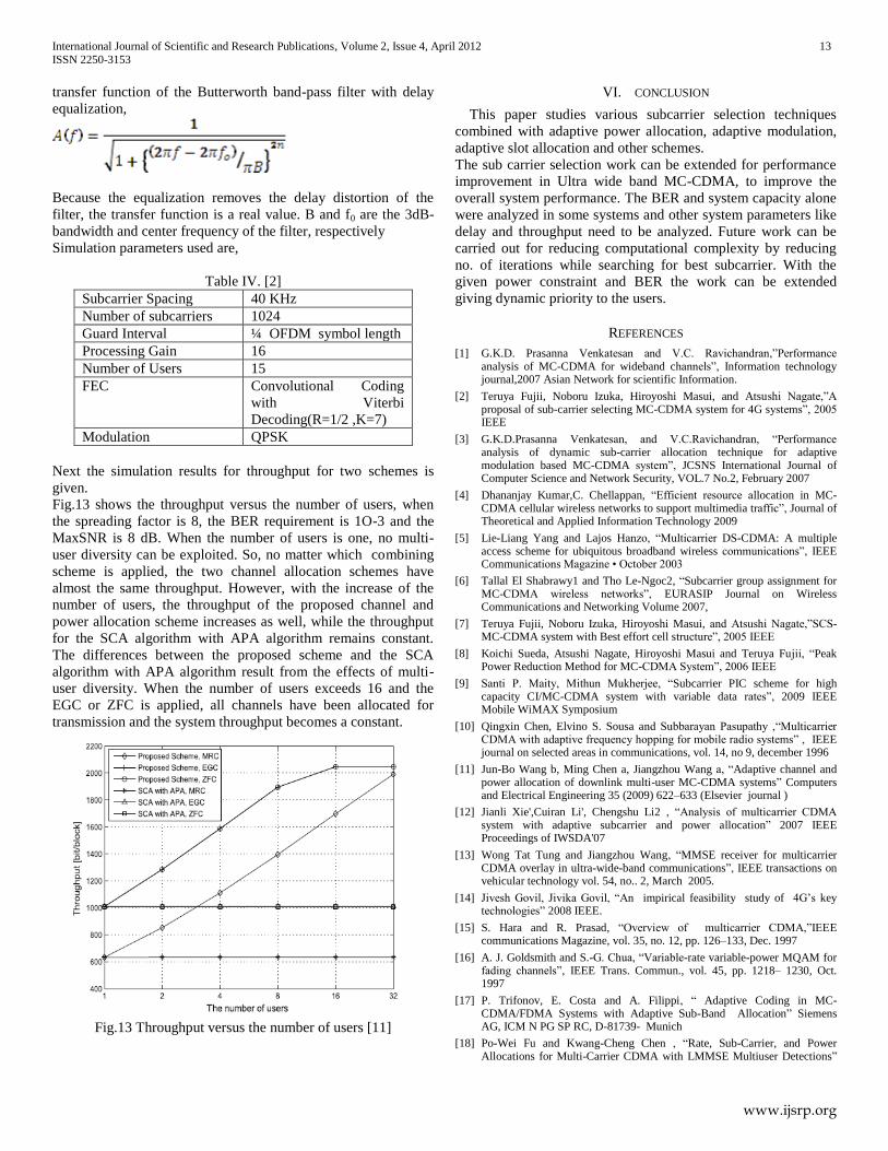
Next the simulation results for throughput for two schemes is
given.
Fig.13 shows the throughput versus the number of users, when
the spreading factor is 8, the BER requirement is 1O-3 and the
MaxSNR is 8 dB. When the number of users is one, no multi-
user diversity can be exploited. So, no matter which combining
scheme is applied, the two channel allocation schemes have
almost the same throughput. However, with the increase of the
number of users, the throughput of the proposed channel and
power allocation scheme increases as well, while the throughput
for the SCA algorithm with APA algorithm remains constant.
The differences between the proposed scheme and the SCA
algorithm with APA algorithm result from the effects of multi-
user diversity. When the number of users exceeds 16 and the
EGC or ZFC is applied, all channels have been allocated for
transmission and the system throughput becomes a constant.
Fig.13 Throughput versus the number of users [11]
VI. CONCLUSION
This paper studies various subcarrier selection techniques
combined with adaptive power allocation, adaptive modulation,
adaptive slot allocation and other schemes.
The sub carrier selection work can be extended for performance
improvement in Ultra wide band MC-CDMA, to improve the
overall system performance. The BER and system capacity alone
were analyzed in some systems and other system parameters like
delay and throughput need to be analyzed. Future work can be
carried out for reducing computational complexity by reducing
no. of iterations while searching for best subcarrier. With the
given power constraint and BER the work can be extended
giving dynamic priority to the users.
REFERENCES
[1] G.K.D. Prasanna Venkatesan and V.C. Ravichandran,”Performance analysis of MC-CDMA for wideband channels”, Information technology journal,2007 Asian Network for scientific Information.
[2] Teruya Fujii, Noboru Izuka, Hiroyoshi Masui, and Atsushi Nagate,”A proposal of sub-carrier selecting MC-CDMA system for 4G systems”, 2005 IEEE
[3] G.K.D.Prasanna Venkatesan, and V.C.Ravichandran, “Performance analysis of dynamic sub-carrier allocation technique for adaptive modulation based MC-CDMA system”, JCSNS International Journal of Computer Science and Network Security, VOL.7 No.2, February 2007
[4] Dhananjay Kumar,C. Chellappan, “Efficient resource allocation in MC-CDMA cellular wireless networks to support multimedia traffic”, Journal of Theoretical and Applied Information Technology 2009
[5] Lie-Liang Yang and Lajos Hanzo, “Multicarrier DS-CDMA: A multiple access scheme for ubiquitous broadband wireless communications”, IEEE Communications Magazine • October 2003
[6] Tallal El Shabrawy1 and Tho Le-Ngoc2, “Subcarrier group assignment for MC-CDMA wireless networks”, EURASIP Journal on Wireless Communications and Networking Volume 2007,
[7] Teruya Fujii, Noboru Izuka, Hiroyoshi Masui, and Atsushi Nagate,”SCS-MC-CDMA system with Best effort cell structure”, 2005 IEEE
[8] Koichi Sueda, Atsushi Nagate, Hiroyoshi Masui and Teruya Fujii, “Peak Power Reduction Method for MC-CDMA System”, 2006 IEEE
[9] Santi P. Maity, Mithun Mukherjee, “Subcarrier PIC scheme for high capacity CI/MC-CDMA system with variable data rates”, 2009 IEEE Mobile WiMAX Symposium
[10] Qingxin Chen, Elvino S. Sousa and Subbarayan Pasupathy ,“Multicarrier CDMA with adaptive frequency hopping for mobile radio systems” , IEEE journal on selected areas in communications, vol. 14, no 9, december 1996
[11] Jun-Bo Wang b, Ming Chen a, Jiangzhou Wang a, “Adaptive channel and power allocation of downlink multi-user MC-CDMA systems” Computers and Electrical Engineering 35 (2009) 622–633 (Elsevier journal )
[12] Jianli Xie',Cuiran Li', Chengshu Li2 , “Analysis of multicarrier CDMA system with adaptive subcarrier and power allocation” 2007 IEEE Proceedings of IWSDA'07
[13] Wong Tat Tung and Jiangzhou Wang, “MMSE receiver for multicarrier CDMA overlay in ultra-wide-band communications”, IEEE transactions on vehicular technology vol. 54, no.. 2, March 2005.
[14] Jivesh Govil, Jivika Govil, “An impirical feasibility study of 4G’s key technologies” 2008 IEEE.
[15] S. Hara and R. Prasad, “Overview of multicarrier CDMA,”IEEE communications Magazine, vol. 35, no. 12, pp. 126–133, Dec. 1997
[16] A. J. Goldsmith and S.-G. Chua, “Variable-rate variable-power MQAM for fading channels”, IEEE Trans. Commun., vol. 45, pp. 1218– 1230, Oct. 1997
[17] P. Trifonov, E. Costa and A. Filippi, “ Adaptive Coding in MC-CDMA/FDMA Systems with Adaptive Sub-Band Allocation” Siemens AG, ICM N PG SP RC, D-81739- Munich
[18] Po-Wei Fu and Kwang-Cheng Chen , “Rate, Sub-Carrier, and Power Allocations for Multi-Carrier CDMA with LMMSE Multiuser Detections”
International Journal of Scientific and Research Publications, Volume 2, Issue 4, April 2012 14
ISSN 2250-3153
www.ijsrp.org
2005 IEEE 16th International Symposium on Personal, Indoor and Mobile Radio Communications.
[19] Jun-Bo Wang1, Hua-Min Chen2, Ming Chen2, and Xinhua Xue2,” Adaptive Subcarrier Grouping for Downlink MC-CDMA Systems with MMSE Receiver” 2010 IEEE
AUTHORS
First Author – Hema Kale, ETC Department , Jhulelal Institute
of Technology Nagpur , India.
Email id - [email protected]
Second Author – C.G. Dethe, Hema Kale, ETC Department ,
Jhulelal Institute of Technology Nagpur , India.
Email id – [email protected]
Third Author – M.M. Mushrif, ETC Department, Yashwantrao
Chavan College of Engineering, Nagpur, India
Email id - [email protected]