Embed Size (px)
Citation preview
56 hf-praxis 8/2018
RF & Wireless
Demand for high-power RF and microwave device calibration is higher than ever. Technological advances in automation, semi-conductor, and communications applications are largely respon-sible for this increased demand, and have pushed the traditional limits of high power RF metro-logy to higher frequencies and higher power levels. Frequency and power are not the only boundaries being chal-lenged however. These new and improved technologies also bring a mandate for lower uncertain-ties. Low-uncertainty high power RF measurement is especially critical for industries such as semiconductor manufacture, but it’s important to all industries involved in high power appli-cations in both commercial and governmental sectors. Low-uncertainty high-power RF metrology poses unique chal-lenges and requires specialized equipment and measurement techniques to ensure repeatable, accurate measurements. In this
paper, we will provide a broad overview of commonly-used high-power RF measurement techniques, and examine the advantages and disadvantages of each.
We will discuss the equipment required, typical measurement uncertainties, and the power and frequency limits of each. Lastly, we will identify the applications best served by each methodo-logy. See Table 2 for a summary of each of the methods.
For purposes of this paper, mea-surement uncertainties have been normalized to 2-sigma to facilitate easy comparison bet-ween methodologies. However, be aware that uncertainties may be presented at different confi-dence levels between manufac-turers, and sometimes inconsi-stently between product lines from the same manufacturer. Always carefully read the pro-duct datasheets and manuals to properly characterize reported uncertainties.
General Considerations
High-Power Measurement Equipment
High-power RF Test stations typically require specialized, purpose-built equipment. High-quality signal generators, ampli-fiers, and filters are necessary to supply low-distortion test signals at the measured power and fre-quency points. Building such a test station can be an expen-sive proposition, so thoroughly understanding the options availa-ble is even more important.
Filters are especially critical as minimal harmonic distortion is required to ensure accurate measurements. Low-uncertainty measurements often require 2nd harmonic distortion to be bet-ter than -50 dBc, which can be challenging for amplified CW signals.
Filters must be designed for the particular frequencies and power levels to be tested, with minimal
High-Power RF Measurement: Techniques and Methods
TEGAM INC. www.tegam.com
AR Technologies www.arworld.us
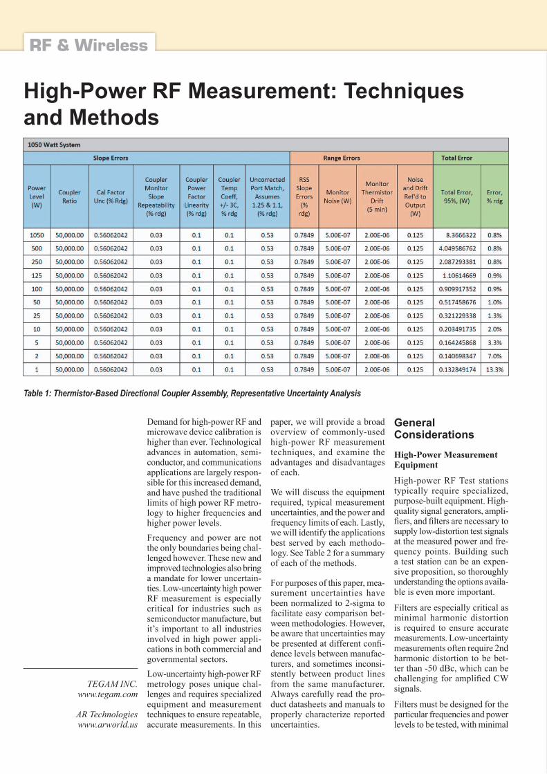
Table 1: Thermistor-Based Directional Coupler Assembly, Representative Uncertainty Analysis

hf-praxis 8/2018 57
RF & Wireless
VSWR and insertion loss across the specified measurement range. Filters may be stand-alone, or designed into measurement devices. But with either configu-ration, it’s important to verify the system’s harmonic suppression characteristics prior to making traceable measurements.Test stations must also include a load capable of dissipating the expected power levels to be measured.
Measurement Considerations High-power RF measurement can present challenges more easily handled in lower-power applications. When measuring high-power, measurement errors such as port reflection and mis-match, insertion loss, power line-arity, and tolerance to thermal transients become significantly more important.These topics are beyond the scope of this paper, but will be discussed in detail in upcoming releases from TEGAM. Please visit www.tegam.com, or call us at 440-466-6100 for more infor-mation regarding high-power RF measurement instruments, uncertainties, and procedures.
Techniques and Methods RF Wattmeter The most straight-forward method for measuring high-power RF is the use of a simple wattmeter. Available in a wide array of designs, wattmeters are a cost-effective method for RF measurement in the 100 mW to 10 kW power range. Wattmeters typically use a diode-detection circuit to measure RF power across a transmission line. The wattmeter is connected inline with the device under test, and can measure both for-ward and reflected power. These instruments are often designed to be portable with the indica-ting meter and measurement elements packaged as a single unit. The portability and versa-tility of wattmeters make them well-suited for field work.
However, these conveniences come at the expense of accu-racy. Wattmeters typically pro-vide measurement uncertainties in the 3% to 10% range. This is often acceptable for field appli-cations such as tuning an antenna for optimal impedance or making a “go, no-go” measurement of a radar station. For metrological measurements however, these high measurement uncertainties are unacceptable.
Directional Power Sensors
Directional power sensors are similar to traditional RF watt-meters. They typically employ a diode-detection circuit that converts RF power to a voltage, and can be used to measure both forward and reflected power. Some models provide the abi-lity to change connector styles, thereby supporting a wider range of test devices. Similar to watt-meters, directional power sen-sors are designed to cover rela-tively narrow frequency bands necessitating the purchase of multiple models for broadband applications.
However, there are several key differences as well. First, direc-tional power sensors typically do not include a meter or other indicator on the sensor. Instead, they require an external meter.
Secondly, directional power sensors often provide improved measurement uncertainty over traditional wattmeters. At spe-cific calibrated frequencies and power levels, directional power sensors can be as good as ± 2%. Uncertainty can be considerably worse at points other than the calibration points though. Users should therefore carefully exa-mine the sensor’s measurement uncertainty at all frequencies and power levels of interest before making traceable measurements.
Directional power sensors pro-vide an acceptable bridge bet-ween field and laboratory work. However, the requirement of a separate meter / indicator makes them less portable than RF watt-meters, and they have narrower frequency ranges and worse uncertainties than the directional
couple assemblies and calorime-ters discussed below.
Directional Coupler Assemblies Directional coupler assemblies can be used similarly to direc-tional power sensors, but rely on fundamentally different techno-logies to make power measure-ments. They utilize a low-power RF sensor paired with a directio-nal coupler to measure RF power levels beyond the usual power range of the sensor. They also often include a large heat sink to dissipate heat gene-rated at the coupled port of the directional coupler. Dissipa-ted RF power is converted to heat energy inside the coupler, which can induce variability in the coupling coefficient. These variabilities are difficult to pre-dict, and can significantly impact repeatability and absolute mea-surement accuracy. A heat sink properly positioned and sized to wick away thermal changes within the coupler will mitigate these uncertainties. Directional coupler assemblies can be configured using either diode- or thermistor-based sen-sors. The dynamic range of the assembly is primarily determined by the coupler used, and the assembly’s overall measurement uncertainty is the combination of the directional coupler power linearity and directivity, and the calibration factor uncertainty of the sensor. In short, the better the sensor and coupler, the better the final measurement uncertainty. Directional coupler assemblies provide two major advantages over the directional power sensor approach. First, coupler assem-blies can cover a much wider frequency bands. Compared to a directional power sensor, cou-pler assemblies are relatively flat over wide frequency ranges and can be calibrated to provide a reasonably accurate, single-device solution for wideband power measurement. Second, directional coupler assemblies typically have better measurement uncertainty across their frequency and power ranges
than directional power sensors, with thermistor-based assemblies providing better uncertainties than diode-based assemblies. Diode sensors typically report power readings relative to a reference, usually 50 MHz. In practical terms this means that before each use, the sensor must be disconnected from the direc-tional coupler assembly, con-nected to the 50 MHz reference port on the system power meter, standardized, then reconnected to the assembly. This sensor dis-connect and reconnect introduces a significant and sometimes dif-ficult-to-calculate uncertainty to the final measurement. Further, the 50 MHz reference itself will contribute a sizable uncertainty to the measurement. Thermistor-based assemblies however measure absolute power and can therefore be per-manently fixed to the coupler assembly, resulting in much-improved measurement uncer-tainty. This combined with the better uncertainty of thermistor sensors generally, results in a better overall uncertainty com-pared to diode-based assemblies, and much better than directional power sensors. Uncertainties of better than 1% can be achieved with a properly calibrated ther-mistor-based coupler assembly.Linearity is also an important consideration when selecting between diode- or thermistor-based coupler assemblies. Line-arity measures the response of a sensor compared to changes to input power. For instance, if input power is doubled, a per-fectly linear sensor’s measured power will also double. Diode sensors have a wide dyna-mic range, with some popular sensors covering ranges as large as -70 to +30 dBm. However, nonlinearity across this range can be as much as 5%, depen-ding on the sensor design. When calculating total system uncer-tainty, it’s important to account for this nonlinearity. Thermistor sensors on the other hand have a limited dynamic range, but excellent linearity across that range. A typical ther-
58 hf-praxis 8/2018
RF & Wireless
mistor assembly has a dynamic range of -20 to +10 dBm. Nonli-nearity however can be as good a 0.1% across that range. This again leads to much better total system uncertainty when using a thermistor sensor.
As mentioned above, directio-nal coupler assemblies are often attached to large heat-sinks and are therefore less portable than wattmeters and directional power sensors. Thermistor sensors also respond marginally slower than their diode-based cousins. However, for applications such as RF plasma generator calibra-tion, semiconductor manufac-ture, and RF amplifier testing, directional coupler assemblies are ideal. These applications require the low uncertainties provided by coupler assemblies without sacrificing workload throughput.
Table 1 highlights a represen-tative uncertainty analysis for a typical thermistor-based directio-nal coupler assembly. Note that from 10% to 100% of full power, reading error remains relatively flat at less than 1%, while power readings at less than 1% yield higher errors. The data in Table 1 is for a 1050 W assembly, but assemblies designed for lower or higher power will respond similarly.
Calorimeters stand alone among the other methodologies dis-cussed in this paper. They pro-vide the best available mea-surement uncertainty, but are very slow compared to other techniques. Generally, they are used in the laboratory to cali-brate working standards such as directional coupler assemblies, directional power sensors, and wattmeters.
Calorimeters are thermal devices
A source RF signal is applied to a load inside the calorimeter, through which a liquid is circula-ted at a known flow rate. A ther-mal transfer occurs between the load and liquid, proportional to the RF signal source. That tem-perature delta is then measured as a thermocouple voltage from which the applied RF power level can be derived.
To make accurate measurements using this process, calorimeters must carefully monitor and con-trol the flow rate of the liquid through the load, and any poten-tials for heat loss in the system must be minimized. Calorime-ters require the same amplifiers and filters used in the preceding methodologies, but also require a chiller to maintain precise tem-perature control of the circulated liquid. Because of this, calori-
meters are usually permanently installed in the lab, and often placed in a dedicated area de-signed to properly handle excess heat and noise from the chiller and other equipment.
As mentioned above, calorime-ters are comparatively slow-mea-suring devices. Precise control of the circulated liquid and stabili-zation of the RF signal thermal transfer can take a considerable amount of time. Direct-reading systems that utilize high-quality chillers coupled with precision flow-control circuitry can take 10 to 15 minutes per measurement. Other systems use a substitution measurement approach, compa-ring the thermal delta of an RF source signal to that of an easily-measurable DC signal, and can take several hours per measure-ment. Another consideration in calorimetry is heat loss within the system. Careful calorimeter design will minimize the poten-
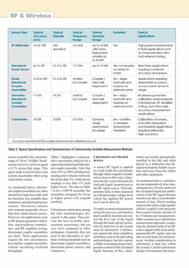
Table 2: Typical Specifications and Characteristics of Commercially Available Measurement Methods
hf-praxis 8/2018 59
RF & Wireless
tial for thermal dissipation bet-ween the load and measurement circuit. Individual thermocoup-les are often used to measure the thermal delta, and can provide reasonable measurement uncer-tainty. But inherent in the design, they introduce opportunity for heat loss. Packaged thermopiles however minimize thermal loss in the system, while still provi-ding very accurate temperature measurements.
Accuracy is the primary advan-tage of the calorimeter. Direct-reading systems are now availa-
ble with measurement uncer-tainty better than 0.5% across their frequency and power ranges.
Conclusion Making high-power RF measure-ments presents unique challen-ges, both in terms of equipment requirements and maintaining measurement uncertainties sui-table for the application at hand. There are advantages to each of the methods discussed in this paper, and careful considera-tion and research is necessary
to choose the method that best balances measurement uncer-tainty, portability, frequency ranges, and dynamic range.
While RF wattmeters or direc-tional sensors are often ideal for field measurements at very par-ticular frequencies, they have larger reading error than other methods. Directional coupler assemblies can measure across a wider frequency range but are not generally suitable for field work. Additionally, thermistor-based directional coupler assem-blies provide significantly impro-
ved measurement uncertainties. Lastly, calorimeters will provide the lowest measurement uncer-tainty, but can only be used in lab environments and are much slower than the other methods discussed.
Table 2 provides a brief sum-mary of the key characteristics of the methods discussed above. This data provides an over-view of commercially available instruments, but please refer to manufacturers’ published spe-cifications for full performance information. ◄