Embed Size (px)
Citation preview
Service guide
Date of issue January 2020
Form number 670639
Version 2
Models7795-A5 and 7795-B5
High pressure grease pump
Declaration of conformity as defined by Machinery Directive 2006/42/EC This is to declare that the design of the low pressure fluid lubricant pump complies with the provisions of directive 2006/42/CG
Applied standards:
• EN 292-1 Safety of Machinery - Basic Concepts, General Principles and Design - Part 1: Basic Terminology, Methodology.
• EN 292-2 Safety of Machinery - Basic Concepts, General Principles and Design - Part 2: Technical Principles and Specifi-cations -
Incorporates amendments 1 (1995) and 2 (1997) EN 809 Pumps and Pump Units for Liquids - Common Safety Requirements.
• EN 349 Safety of Machinery - Minimum Gaps to Avoid Crushing of Parts of the Human Body.
St. Louis, MO 08/14, Robert Hoefler, Director Product Development and Product Engineering
2
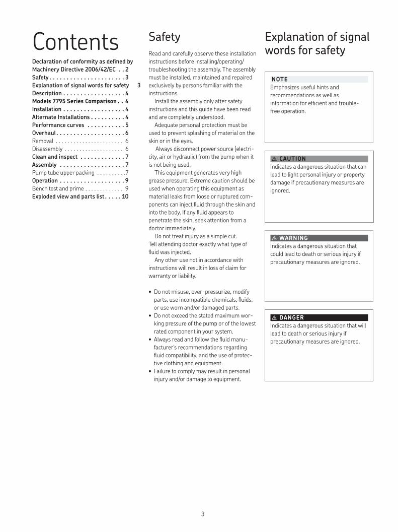
NOTEEmphasizes useful hints and recommendations as well as information for efficient and trouble-free operation.
� CAUTIONIndicates a dangerous situation that can lead to light personal injury or property damage if precautionary measures are ignored.
� WARNINGIndicates a dangerous situation that could lead to death or serious injury if precautionary measures are ignored.
� DANGERIndicates a dangerous situation that will lead to death or serious injury if precautionary measures are ignored.
Explanation of signal words for safety
SafetyRead and carefully observe these installation instructions before installing/operating/troubleshooting the assembly. The assembly must be installed, maintained and repaired exclusively by persons familiar with the instructions.
Install the assembly only after safety instructions and this guide have been read and are completely understood.
Adequate personal protection must be used to prevent splashing of material on the skin or in the eyes.
Always disconnect power source (electri-city, air or hydraulic) from the pump when it is not being used.
This equipment generates very high grease pressure. Extreme caution should be used when operating this equipment as material leaks from loose or ruptured com-ponents can inject fluid through the skin and into the body. If any fluid appears to penetrate the skin, seek attention from a doctor immediately.
Do not treat injury as a simple cut. Tell attending doctor exactly what type of fluid was injected.
Any other use not in accordance with instructions will result in loss of claim for warranty or liability.
• Do not misuse, over-pressurize, modify parts, use incompatible chemicals, fluids, or use worn and/or damaged parts.
• Do not exceed the stated maximum wor-king pressure of the pump or of the lowest rated component in your system.
• Always read and follow the fluid manu-facturer’s recommendations regarding fluid compatibility, and the use of protec-tive clothing and equipment.
• Failure to comply may result in personal injury and/or damage to equipment.
ContentsDeclaration of conformity as defined by Machinery Directive 2006/42/EC 2Safety 3Explanation of signal words for safety 3Description 4Models 7795 Series Comparison 4Installation 4Alternate Installations 4Performance curves 5Overhaul 6Removal . . . . . . . . . . . . . . . . . . . . . . . 6Disassembly . . . . . . . . . . . . . . . . . . . . 6Clean and inspect 7Assembly 7Pump tube upper packing . . . . . . . . . .7Operation 9Bench test and prime . . . . . . . . . . . . . 9Exploded view and parts list 10
3
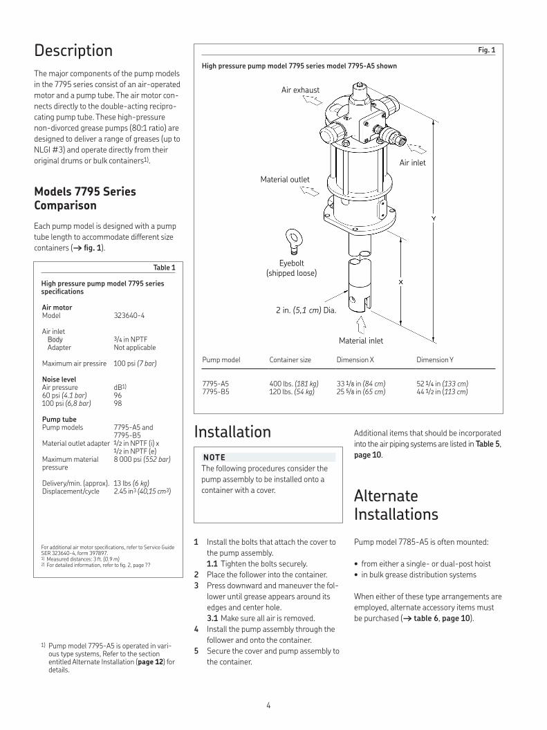
Table 1
High pressure pump model 7795 series specifications
Air motorModel 323640-4
Air inletBody 3/4 in NPTFAdapter Not applicable
Maximum air pressire 100 psi (7 bar)
Noise levelAir pressure dB1)60 psi (4.1 bar) 96 100 psi (6,8 bar) 98
Pump tubePump models 7795-A5 and
7795-B5Material outlet adapter 1/2 in NPTF (i) x
1/2 in NPTF (e)Maximum material pressure
8 000 psi (552 bar)
Delivery/min. (approx). 13 lbs (6 kg)Displacement/cycle 2.45 in3 (40,15 cm3)
Fig 1
High pressure pump model 7795 series model 7795-A5 shownDescriptionThe major components of the pump models in the 7795 series consist of an air-operated motor and a pump tube. The air motor con-nects directly to the double-acting recipro-cating pump tube. These high-pressure non-divorced grease pumps (80:1 ratio) are designed to deliver a range of greases (up to NLGI #3) and operate directly from their original drums or bulk containers1).
Models 7795 Series ComparisonEach pump model is designed with a pump tube length to accommodate different size containers (→ fig 1).
Air exhaust
Air inlet
Material outlet
Eyebolt(shipped loose)
Material inlet
2 in. (5,1 cm) Dia.
Pump model Container size Dimension X Dimension Y
7795-A5 400 lbs. (181 kg) 33 1/8 in (84 cm) 52 1/4 in (133 cm)7795-B5 120 lbs. (54 kg) 25 5/8 in (65 cm) 44 1/2 in (113 cm)
For additional air motor specifications, refer to Service Guide SER 323640-4, form 397897.1) Measured distances: 3 ft. (0.9 m)2) For detailed information, refer to fig. 2, page ??
1) Pump model 7795-A5 is operated in vari-ous type systems, Refer to the section entitled Alternate Installation (page 12) for details.
NOTEThe following procedures consider the pump assembly to be installed onto a container with a cover.
Installation Additional items that should be incorporated into the air piping systems are listed in Table 5, page 10.
Alternate InstallationsPump model 7785-A5 is often mounted:
• from either a single- or dual-post hoist• in bulk grease distribution systems
When either of these type arrangements are employed, alternate accessory items must be purchased (→ table 6, page 10).
1 Install the bolts that attach the cover to the pump assembly.1 1 Tighten the bolts securely.
2 Place the follower into the container.3 Press downward and maneuver the fol-
lower until grease appears around its edges and center hole.3 1 Make sure all air is removed.
4 Install the pump assembly through the follower and onto the container.
5 Secure the cover and pump assembly to the container.
4
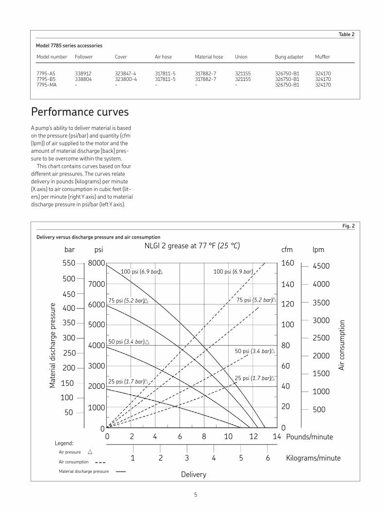
Table 2
Model 7785 series accessories
Model number Follower Cover Air hose Material hose Union Bung adapter Muffler
7795-A5 338912 323847-4 317811-5 317882-7 321155 326750-B1 3241707795-B5 338804 323800-4 317811-5 317882-7 321155 326750-B1 3241707795-MA - - - - - 326750-B1 324170
Performance curvesA pump’s ability to deliver material is based on the pressure (psi/bar) and quantity (cfm (lpm)) of air supplied to the motor and the amount of material discharge [back] pres-sure to be overcome within the system.
This chart contains curves based on four different air pressures. The curves relate delivery in pounds (kilograms) per minute (X axis) to air consumption in cubic feet (lit-ers) per minute (right Y axis) and to material discharge pressure in psi/bar (left Y axis).
Fig 2
Delivery versus discharge pressure and air consumptionNLGI 2 grease at 77 °F (25 °C)bar psi
Mat
erial
disc
harg
e pr
essu
re
550
500
450400
350
300
250
200
150
100
50
8000
7000
6000
5000
4000
3000
2000
1000
0
100 psi (6.9 bar) 100 psi (6.9 bar)
75 psi (5.2 bar) 75 psi (5.2 bar)
50 psi (3.4 bar)50 psi (3.4 bar)
25 psi (1.7 bar) 25 psi (1.7 bar)
Legend:Air pressure
Air consumption
Material discharge pressure
0 2 4 6 8 10 12 14 Pounds/minute
Delivery
1 2 3 4 5 6 Kilograms/minute
Air c
onsu
mpt
ion
cfm lpm160
140
120
100
80
60
40
20
0
4500
4000
3500
3000
2500
2000
1500
1000
500
5
Overhaul
Removal
12 Remove aluminum gasket (20), washer (21), and additional gasket (20) from the body.
13 Remove spacer (19), washer (18), and seal (17).
14 Remove lantern ring (16) with seal (15), and spacer (14).14 1 Remove the seal from the lantern
ring.15 Remove o-ring (13), o-ring (9), and
o-ring (10) from the body.
Pump tube16 Clamp the pump tube assembly at
adapter (41) securely in a soft-jaw vise.17 Unscrew and remove pump tube (26)
from the adapter.18 Remove upper and lower spring clips (24)
that secure pump tube rod (25) to upper and lower couplings (23).
19 Unscrew the rod from both couplings.
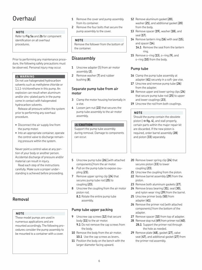
NOTERefer to Fig 5a and 2b for component identification on all overhaul procedures.
Prior to performing any maintenance proce-dure, the following safety precautions must be observed. Personal injury may occur.
� WARNINGDo not use halogenated hydrocarbon solvents such as methylene chloride or 1,1,1-trichlorethane in this pump. An explosion can result when aluminum and/or zinc-plated parts in the pump come in contact with halogenated hydrocarbon solvents.
Release all pressure within the system prior to performing any overhaul procedure.
• Disconnect the air supply line from the pump motor.
• Into an appropriate container, operate the control valve to discharge remain-ing pressure within the system.
Never point a control valve at any por-tion of your body or another person. Accidental discharge of pressure and/or material can result in injury.
Read each step of the instructions carefully. Make sure a proper under-standing is achieved before proceeding.
NOTEThese model pumps are used in numerous applications and are mounted accordingly. The following pro-cedures consider the pump assembly to be mounted to a container with a cover.
1 Remove the cover and pump assembly from its container.
2 Remove the four bolts that secure the pump assembly to the cover.
NOTERemove the follower from the bottom of the container.
Disassembly
1 Unscrew adapter (5) from air motor assembly (2).
2 Remove washer (7) and rubber bushing (8).
Separate pump tube from air motor3 Clamp the motor housing horizontally in
a vise.4 Loosen jam nut (22) that secures the
pump tube assembly to the air motor assembly.
� CAUTIONSupport the pump tube assembly during removal. Damage to components can occur.
5 Unscrew pump tube (26) [with attached components] from the air motor.
6 Pull on the pump tube to expose cou-pling (23).
7 Remove upper spring clip (24) that secures pump tube rod (25) to coupling (23).
8 Unscrew the coupling from the air motor piston rod.8 1 Rotate the entire pump tube
assembly.
Pump tube upper packing9 Unscrew cap screws (12) that secure
body (11) to the air motor.9 1 Do not remove the cap screws from
the body.10 Remove the body from the air motor.
10 1 Use the cap screws as levers.11 Position the body on the bench with the
larger diameter facing upward.
NOTEShould the pump contain the obsolete piston (→ fig 4), and stall properly, certain parts within the major repair kit are discarded. If the new piston is required, order barrel assembly (28) and piston (33) separately.
20 Remove lower spring clip (24) that secures piston (33) to lower coupling (23).
21 Unscrew the coupling from the piston.22 Remove barrel assembly (29) from the
piston.23 Remove both aluminum gaskets (27).24 Remove brass bearing (31), seal (30),
and nylon wear ring (29) from the barrel.25 Unscrew primer body (50) from
adapter (41).26 Remove the primer rod (with attached
components) from the bottom of the adapter.
27 Remove spacer (32) from top of adapter.28 Remove stop nut (49) from primer rod (40).
28 1 Support the primer rod through the hole as needed.
29 Remove plate (48), gasket (27), valve seat (47), and additional gasket (27) from the primer rod assembly.
6
30 Remove roll pin (39) that secures adapter and insert assembly (38) to primer rod (40).30 1 Use a punch and a small hammer.
31 Unscrew primer rod from adapter.32 Remove valve body (46) [with attached
components] and guide washer (42) from the upper end of the primer rod assembly.
33 Remove screw (43), nylon washer (44), seal (45) and additional washer (45) from the valve body.
34 Unscrew the adapter from piston (33).35 Remove aluminum washer (37), ball (36),
spring (35), and retainer (34) from the piston.
Clean and inspect
� CAUTIONSupport the piston and primer rod assembly during roll pin (39) removal. Damage to components can occur.
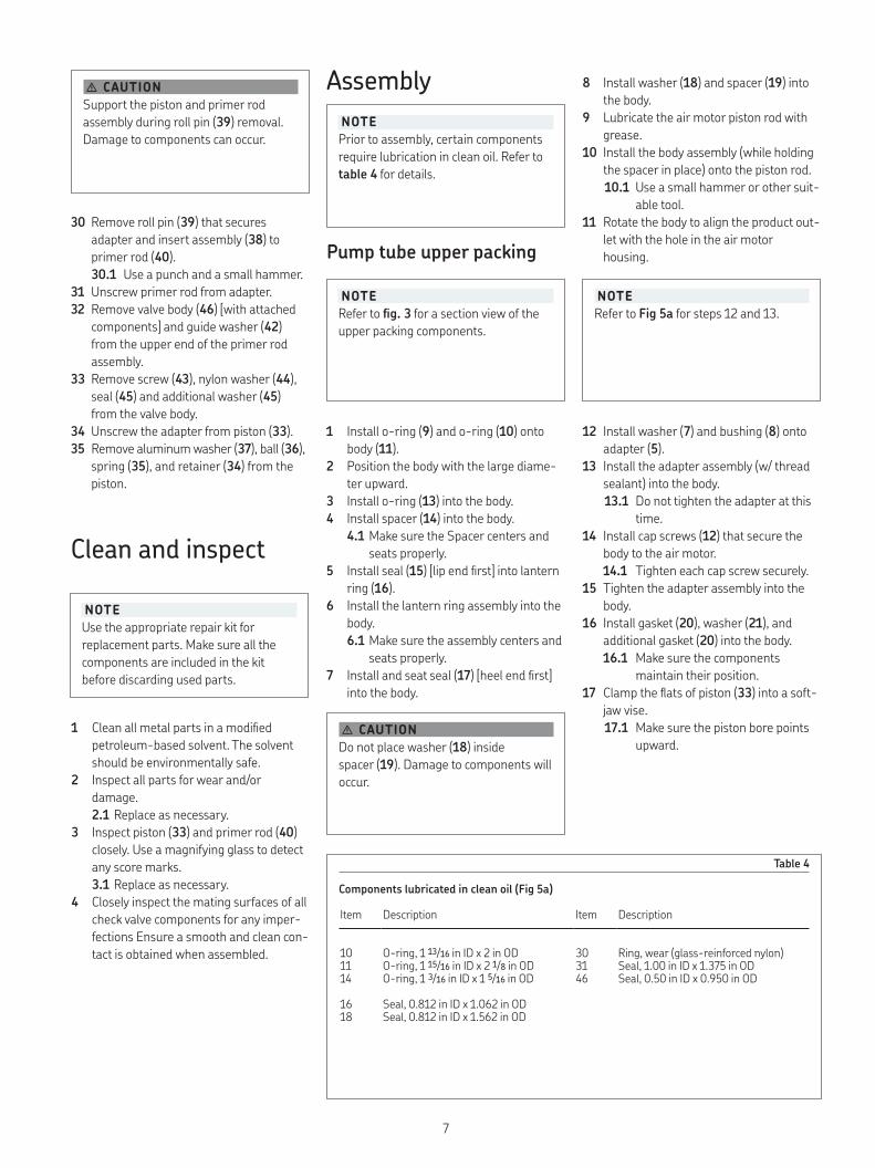
Table 4
Components lubricated in clean oil (Fig 5a)
Item Description Item Description
10 O-ring, 1 13/16 in ID x 2 in OD 30 Ring, wear (glass-reinforced nylon)11 O-ring, 1 15/16 in ID x 2 1/8 in OD 31 Seal, 1.00 in ID x 1.375 in OD14 O-ring, 1 3/16 in ID x 1 5/16 in OD 46 Seal, 0.50 in ID x 0.950 in OD
16 Seal, 0.812 in ID x 1.062 in OD18 Seal, 0.812 in ID x 1.562 in OD
NOTEUse the appropriate repair kit for replacement parts. Make sure all the components are included in the kit before discarding used parts.
1 Clean all metal parts in a modified petroleum-based solvent. The solvent should be environmentally safe.
2 Inspect all parts for wear and/or damage.2 1 Replace as necessary.
3 Inspect piston (33) and primer rod (40) closely. Use a magnifying glass to detect any score marks.3 1 Replace as necessary.
4 Closely inspect the mating surfaces of all check valve components for any imper-fections Ensure a smooth and clean con-tact is obtained when assembled.
AssemblyNOTEPrior to assembly, certain components require lubrication in clean oil. Refer to table 4 for details.
Pump tube upper packing
8 Install washer (18) and spacer (19) into the body.
9 Lubricate the air motor piston rod with grease.
10 Install the body assembly (while holding the spacer in place) onto the piston rod.10 1 Use a small hammer or other suit-
able tool.11 Rotate the body to align the product out-
let with the hole in the air motor housing.
NOTERefer to fig 3 for a section view of the upper packing components.
1 Install o-ring (9) and o-ring (10) onto body (11).
2 Position the body with the large diame-ter upward.
3 Install o-ring (13) into the body.4 Install spacer (14) into the body.
4 1 Make sure the Spacer centers and seats properly.
5 Install seal (15) [lip end first] into lantern ring (16).
6 Install the lantern ring assembly into the body.6 1 Make sure the assembly centers and
seats properly.7 Install and seat seal (17) [heel end first]
into the body.
� CAUTIONDo not place washer (18) inside spacer (19). Damage to components will occur.
NOTERefer to Fig 5a for steps 12 and 13.
12 Install washer (7) and bushing (8) onto adapter (5).
13 Install the adapter assembly (w/ thread sealant) into the body.13 1 Do not tighten the adapter at this
time.14 Install cap screws (12) that secure the
body to the air motor.14 1 Tighten each cap screw securely.
15 Tighten the adapter assembly into the body.
16 Install gasket (20), washer (21), and additional gasket (20) into the body.16 1 Make sure the components
maintain their position.17 Clamp the flats of piston (33) into a soft-
jaw vise.17 1 Make sure the piston bore points
upward.
7
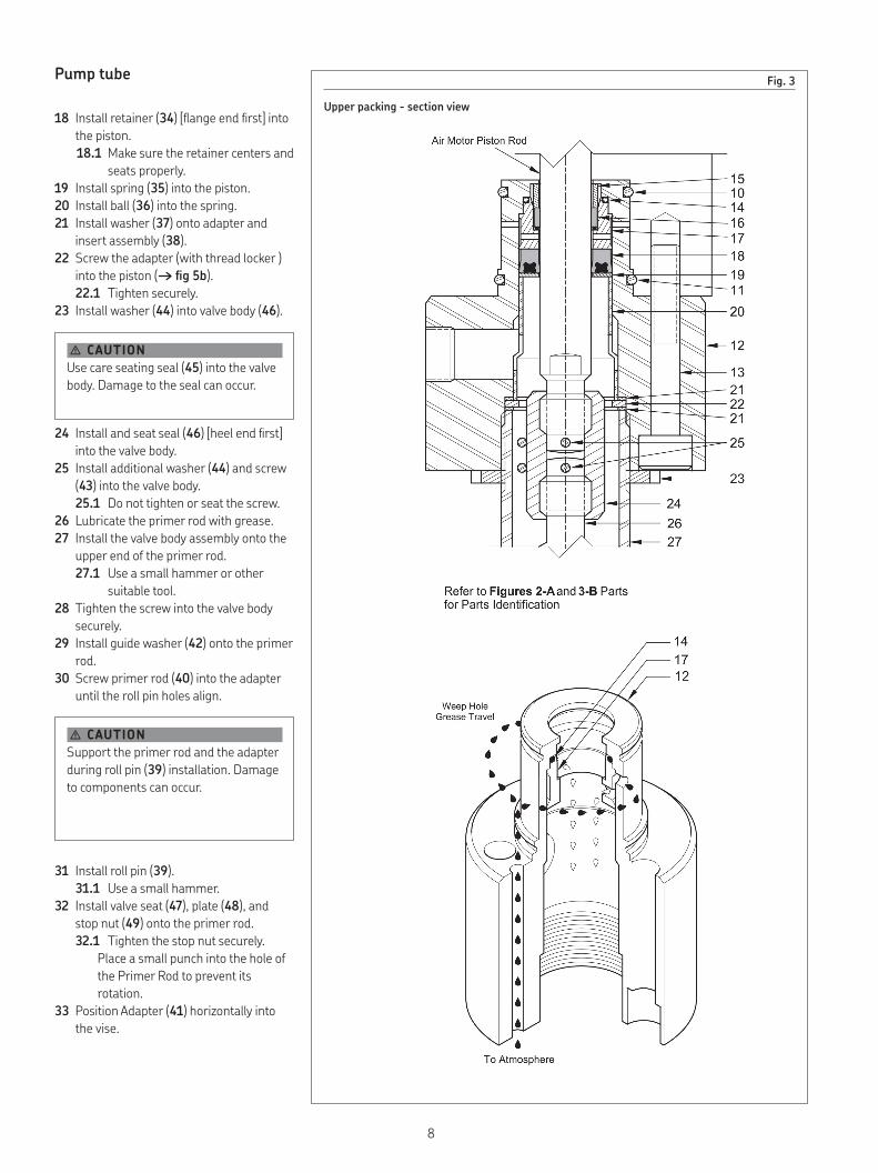
Fig 3
Upper packing - section view
Pump tube
18 Install retainer (34) [flange end first] into the piston.18 1 Make sure the retainer centers and
seats properly.19 Install spring (35) into the piston.20 Install ball (36) into the spring.21 Install washer (37) onto adapter and
insert assembly (38).22 Screw the adapter (with thread locker )
into the piston (→ fig 5b).22 1 Tighten securely.
23 Install washer (44) into valve body (46).
� CAUTIONUse care seating seal (45) into the valve body. Damage to the seal can occur.
24 Install and seat seal (46) [heel end first] into the valve body.
25 Install additional washer (44) and screw (43) into the valve body.25 1 Do not tighten or seat the screw.
26 Lubricate the primer rod with grease.27 Install the valve body assembly onto the
upper end of the primer rod.27 1 Use a small hammer or other
suitable tool.28 Tighten the screw into the valve body
securely.29 Install guide washer (42) onto the primer
rod.30 Screw primer rod (40) into the adapter
until the roll pin holes align.
� CAUTIONSupport the primer rod and the adapter during roll pin (39) installation. Damage to components can occur.
31 Install roll pin (39).31 1 Use a small hammer.
32 Install valve seat (47), plate (48), and stop nut (49) onto the primer rod.32 1 Tighten the stop nut securely.
Place a small punch into the hole of the Primer Rod to prevent its rotation.
33 Position Adapter (41) horizontally into the vise.
8
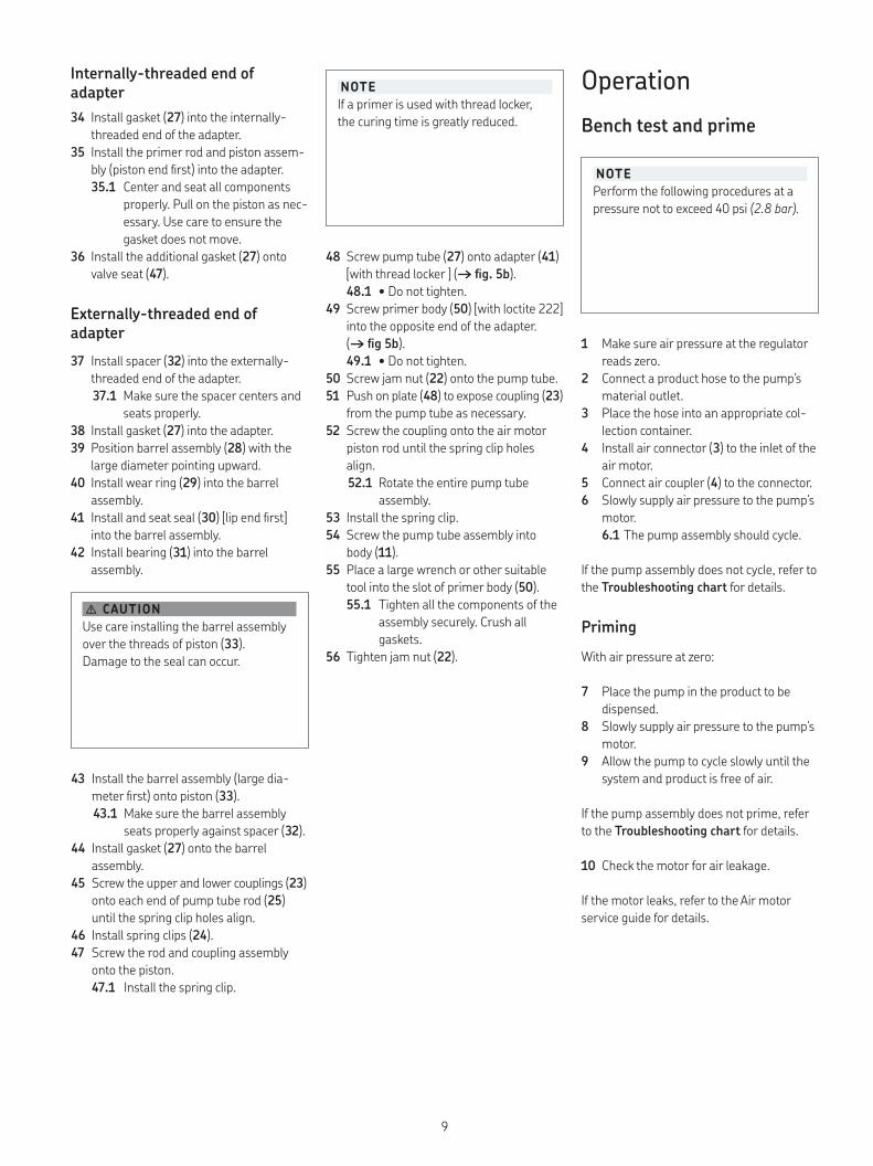
Internally-threaded end of adapter34 Install gasket (27) into the internally-
threaded end of the adapter.35 Install the primer rod and piston assem-
bly (piston end first) into the adapter.35 1 Center and seat all components
properly. Pull on the piston as nec-essary. Use care to ensure the gasket does not move.
36 Install the additional gasket (27) onto valve seat (47).
Externally-threaded end of adapter37 Install spacer (32) into the externally-
threaded end of the adapter.37 1 Make sure the spacer centers and
seats properly.38 Install gasket (27) into the adapter.39 Position barrel assembly (28) with the
large diameter pointing upward.40 Install wear ring (29) into the barrel
assembly.41 Install and seat seal (30) [lip end first]
into the barrel assembly.42 Install bearing (31) into the barrel
assembly.
� CAUTIONUse care installing the barrel assembly over the threads of piston (33). Damage to the seal can occur.
43 Install the barrel assembly (large dia- meter first) onto piston (33).43 1 Make sure the barrel assembly
seats properly against spacer (32).44 Install gasket (27) onto the barrel
assembly.45 Screw the upper and lower couplings (23)
onto each end of pump tube rod (25) until the spring clip holes align.
46 Install spring clips (24).47 Screw the rod and coupling assembly
onto the piston.47 1 Install the spring clip.
NOTEIf a primer is used with thread locker, the curing time is greatly reduced.
48 Screw pump tube (27) onto adapter (41) [with thread locker ] (→ fig 5b).48 1 • Do not tighten.
49 Screw primer body (50) [with loctite 222] into the opposite end of the adapter. (→ fig 5b).49 1 • Do not tighten.
50 Screw jam nut (22) onto the pump tube.51 Push on plate (48) to expose coupling (23)
from the pump tube as necessary.52 Screw the coupling onto the air motor
piston rod until the spring clip holes align.52 1 Rotate the entire pump tube
assembly.53 Install the spring clip.54 Screw the pump tube assembly into
body (11).55 Place a large wrench or other suitable
tool into the slot of primer body (50).55 1 Tighten all the components of the
assembly securely. Crush all gaskets.
56 Tighten jam nut (22).
NOTEPerform the following procedures at a pressure not to exceed 40 psi (2.8 bar).
OperationBench test and prime
1 Make sure air pressure at the regulator reads zero.
2 Connect a product hose to the pump’s material outlet.
3 Place the hose into an appropriate col-lection container.
4 Install air connector (3) to the inlet of the air motor.
5 Connect air coupler (4) to the connector.6 Slowly supply air pressure to the pump’s
motor.6 1 The pump assembly should cycle.
If the pump assembly does not cycle, refer to the Troubleshooting chart for details.
PrimingWith air pressure at zero:
7 Place the pump in the product to be dispensed.
8 Slowly supply air pressure to the pump’s motor.
9 Allow the pump to cycle slowly until the system and product is free of air.
If the pump assembly does not prime, refer to the Troubleshooting chart for details.
10 Check the motor for air leakage.
If the motor leaks, refer to the Air motor service guide for details.
9
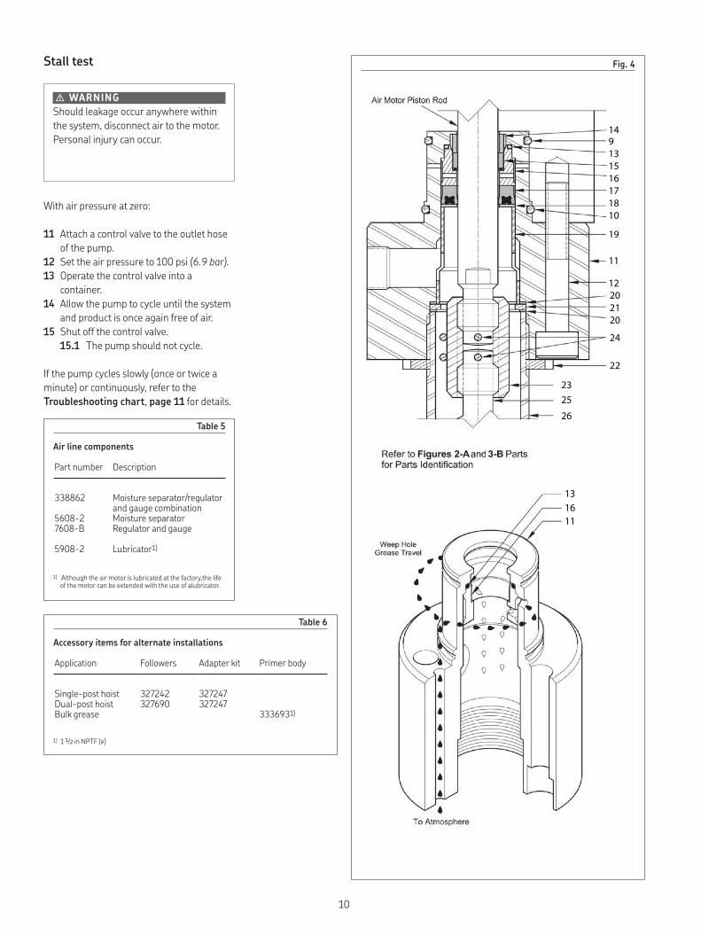
Stall test
� WARNINGShould leakage occur anywhere within the system, disconnect air to the motor. Personal injury can occur.
With air pressure at zero:
11 Attach a control valve to the outlet hose of the pump.
12 Set the air pressure to 100 psi (6.9 bar).13 Operate the control valve into a
container.14 Allow the pump to cycle until the system
and product is once again free of air.15 Shut off the control valve.
15 1 The pump should not cycle.
If the pump cycles slowly (once or twice a minute) or continuously, refer to the Troubleshooting chart, page 11 for details.
Table 5
Air line components
Part number Description
338862 Moisture separator/regulator and gauge combination
5608-2 Moisture separator7608-B Regulator and gauge
5908-2 Lubricator1)
1) Although the air motor is lubricated at the factory,the life of the motor can be extended with the use of alubricator.
Table 6
Accessory items for alternate installations
Application Followers Adapter kit Primer body
Single-post hoist 327242 327247Dual-post hoist 327690 327247Bulk grease 3336931)
1) 1 1/2 in NPTF (e)
Fig 4
149131516171810
19
11
12202120
24
22
2325
26
131611
10
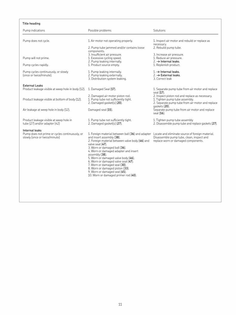
Title heading
Pump indications Possible problems Solutions
Pump does not cycle. 1. Air motor not operating properly.
2. Pump tube jammed and/or contains loose components.3. Insufficient air pressure.
1. Inspect air motor and rebuild or replace as necessary.2. Rebuild pump tube. 3. Increase air pressure.
Pump will not prime. 1. Excessive cycling speed.2. Pump leaking internally.
1. Reduce air pressure.2. → Internal leaks.
Pump cycles rapidly. 1. Product source empty. 1. Replenish product.
Pump cycles continuously, or slowly (once or twice/minute).
1. Pump leaking internally.2. Pump leaking externally.3. Distribution system leaking.
1. → Internal leaks.2. → External leaks.3. Correct leak
External LeaksProduct leakage visible at weep hole in body (12). 1. Damaged Seal (17).
2. Damaged air motor piston rod.
1. Separate pump tube from air motor and replace seal (17).2. Inspect piston rod and replace as necessary.
Product leakage visible at bottom of body (12). 1. Pump tube not sufficiently tight.2. Damaged gasket(s) (20).
1. Tighten pump tube assembly.2. Separate pump tube from air motor and replace gaskets (20).
Air leakage at weep hole in body (12). Damaged seal (15). Separate pump tube from air motor and replace seal (16).
Product leakage visible at weep hole in tube (27) and/or adapter (42)
1. Pump tube not sufficiently tight.2. Damaged gasket(s) (27).
1. Tighten pump tube assembly2. Disassemble pump tube and replace gaskets (27).
Internal leaksPump does not prime or cycles continuously, or slowly (once or twice/minute)
1. Foreign material between ball (36) and adapter and insert assembly (38).2. Foreign material between valve body (46) and valve seat (47).3. Worn or damaged ball (36).4. Worn or damaged adapter and insert assembly (38).5. Worn or damaged valve body (46).6. Worn or damaged valve seat (47).7. Worn or damaged seal (30).8. Worn or damaged piston (33).9. Worn or damaged seal (45).10. Worn or damaged primer rod (40).
Locate and eliminate source of foreign material.Disassemble pump tube, clean, inspect and replace worn or damaged components.
11
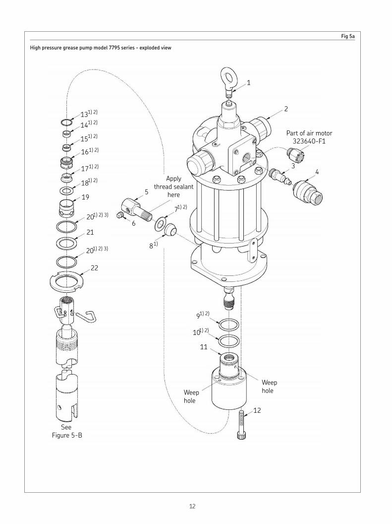
Fig 5a
High pressure grease pump model 7795 series - exploded view
131) 2)
14
15
16
17
1) 2)
1) 2)
1) 2)
1) 2)
181) 2)
19
201) 2) 3)
21
201) 2) 3)
22
See Figure 5-B
12
Weephole
Weephole
11
101) 2)
91) 2)
81)
71) 2)
Applythread sealant
here
6
5
1
2
34
Part of air motor323640-F1
12
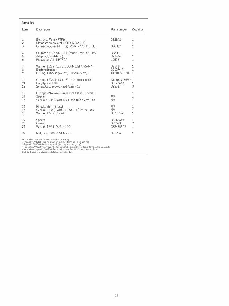
Parts list
Item Description Part number Quantity
1 Bolt, eye, 3/8 in NPTF (e) 323842 12 Motor assembly, air (→ SER 323640-4) 13 Connector, 3/4 in NPTF (e) (Model 7795-A5, -B5) 328037 1
4 Coupler, air, 1/2 in NPTF (i) (Model 7795-A5, -B5) 328031 15 Adapter, 1/2 in NPTF (i) 327706 16 Plug, pipe 1/4 in NPTF (e) 10522 1
7 Washer, 1.29 in (3,3 cm) OD (Model 7795-MA) 323419 18 Bushing (rubber) 3242741)2) 19 O-Ring, 1 13/16 in (4,6 cm) ID x 2 in (5 cm) OD X171009-331) 1
10 O-Ring, 1 15/16 in ID x 2 1/8 in OD (pack of 10) X171009-351)2) 111 Body (pack of 10) 3237861)2) 112 Screw, Cap, Socket Head, 1/2 in - 13 323787 3
13 O-ring 1 3/16 in (4,9 cm) ID x 1 5/16 in (3,3 cm) OD 114 Spacer 1)2) 115 Seal, 0.812 in (2 cm) ID x 1.062 in (2,69 cm) OD 1)2) 1
16 Ring, Lantern (Brass) 1)2) 117 Seal, 0.812 in (2 cm)ID x 1.562 in (3,97 cm) OD 1)2) 118 Washer, 1.55 in (4 cm)OD 3373611)2) 1
19 Spacer 3324661)2) 120 Gasket 323693 221 Washer, 1.93 in (4,9 cm) OD 3324651)2)3) 1
22 Nut, Jam, 2.00 - 16 UN - 2B 333256 1
Part numbers left blank are not available separately1) Repair kit 398988-2 major repair kit (includes items on Fig 5a and 2b).2) Repair kit 393040-1 minor repair kit (for body and seal group)3) Repair kit 393622 minor repair kit (for pump tube assembly) (includes items on Fig 5a and 2b)Not called out: repair kit 393530-5 seal kit (includes five (5) of item number 15) and 393530-6 seal kit (includes five (5) of item number 17).
13
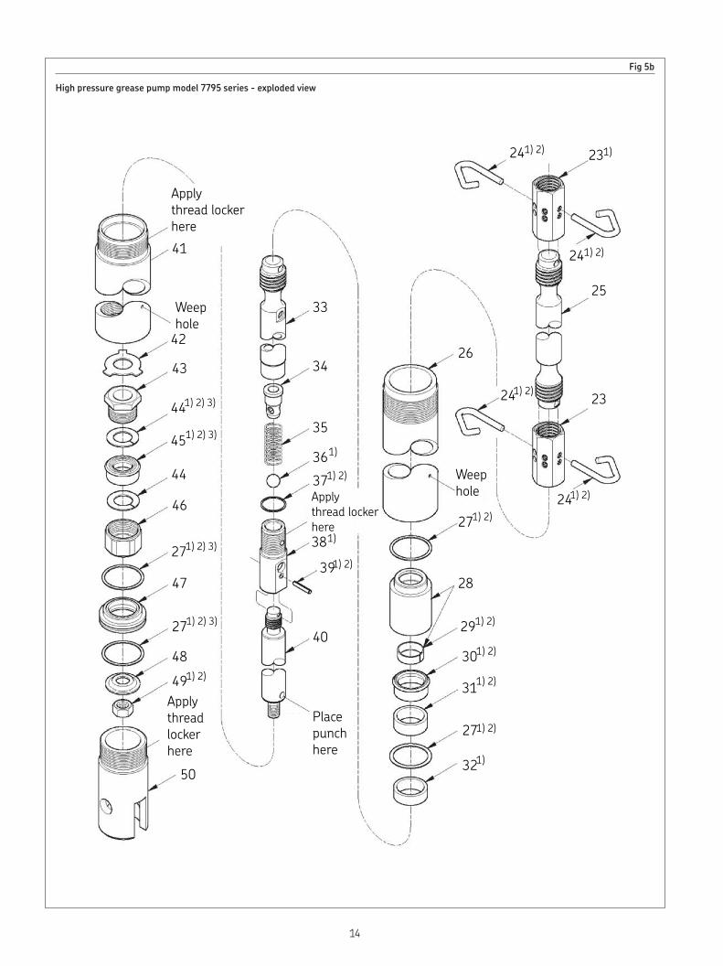
Fig 5b
High pressure grease pump model 7795 series - exploded view
Applythread lockerhere41
Weep hole
42
43
441) 2) 3)
451) 2) 3)
44
46
271) 2) 3)
47
271) 2) 3)
48491) 2)
Applythread lockerhere
Applythread lockerhere
50
33
34
35
361)
371) 2)
381)
391) 2)
40
Placepunchhere
321)
271) 2)
311) 2)
301) 2)
291) 2)
28
271) 2)
Weephole
26
241) 2)
23241) 2)
25
241) 2)
231)241) 2)
14
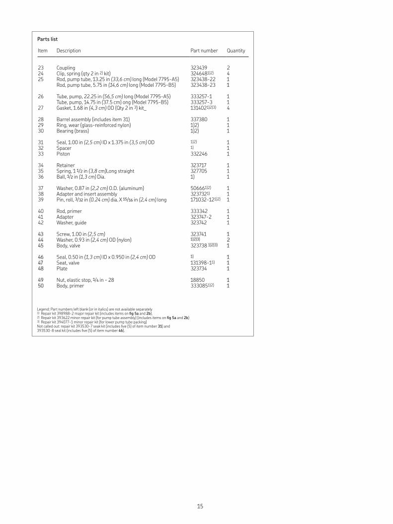
Legend: Part numbers left blank (or in italics) are not available separately1) Repair kit 398988-2 major repair kit (includes items on fig 5a and 2b).2) Repair kit 393622 minor repair kit (for pump tube assembly) (includes items on fig 5a and 2b)3) Repair kit 394077-1 minor repair kit (for lower pump tube packing) Not called out: repair kit 393530-7 seak kit (includes five (5) of item number 31) and 393530-8 seal kit (includes five (5) of item number 46).
Parts list
Item Description Part number Quantity
23 Coupling 323439 224 Clip, spring (qty 2 in 2) kit) 3246481)2) 425 Rod, pump tube, 13.25 in (33,6 cm) long (Model 7795-A5) 323438-22 1
Rod, pump tube, 5.75 in (14,6 cm) long (Model 7795-B5) 323438-23 1
26 Tube, pump, 22.25 in (56,5 cm) long (Model 7795-A5) 333257-1 1Tube, pump, 14.75 in (37.5 cm) ong (Model 7795-B5) 333257-3 1
27 Gasket, 1.68 in (4,3 cm) OD (Qty 2 in 3) kit_ 1314021)2)3) 4
28 Barrel assembly (includes item 31) 337380 129 Ring, wear (glass-reinforced nylon) 1)2) 130 Bearing (brass) 1)2) 1
31 Seal, 1.00 in (2,5 cm) ID x 1.375 in (3,5 cm) OD 1)2) 132 Spacer 1) 133 Piston 332246 1
34 Retainer 323717 135 Spring, 1 1/2 in (3,8 cm)Long straight 327705 136 Ball, 1/2 in (1,3 cm) Dia. 1) 1
37 Washer, 0.87 in (2,2 cm) O.D. (aluminum) 506661)2) 138 Adapter and insert assembly 3237321) 139 Pin, roll, 3/32 in (0.24 cm) dia. X 15/16 in (2,4 cm) long 171032-121)2) 1
40 Rod, primer 333342 141 Adapter 323747-2 142 Washer, guide 323742 1
43 Screw, 1.00 in (2,5 cm) 323741 144 Washer, 0.93 in (2,4 cm) OD (nylon) 1)2)3) 245 Body, valve 323738 1)2)3) 1
46 Seal, 0.50 in (1,3 cm) ID x 0.950 in (2,4 cm) OD 1) 147 Seat, valve 131398-11) 148 Plate 323734 1
49 Nut, elastic stop, 1/4 in - 28 18850 150 Body, primer 3330851)2) 1
15

16

17

18

19

skf com | alemite com® SKF and Alemite, LLC are registered trademark. The contents of this publication are the copyright of the publisher and may not be reproduced (even extracts) unless prior written permission is granted. Every care has been taken to ensure the accuracy of the information contained in this publication but no liability can be accepted for any loss or damage whether direct, indirect or consequential arising out of the use of the information contained herein.
January 2020 · Form 670639 Version 2