Embed Size (px)
Citation preview
Oil Shale, 2013, Vol. 30, No. 2S, pp. 305–325 ISSN 0208-189X doi: 10.3176/oil.2013.2S.10 © 2013 Estonian Academy Publishers
HIGH SELECTIVE OIL SHALE MINING
VIVIKA VÄIZENE*, INGO VALGMA, RIHO ISKÜL, MARGIT KOLATS, MARTIN NURME, VEIKO KARU Department of Mining, Tallinn University of Technology Ehitajate tee 5, 19086 Tallinn, Estonia
Abstract. Several extraction technologies have been used for mining oil shale in Estonia. The quality and properties of the raw material for fuel and oil depend directly on the initial geological properties of the mineral resource. In case of kukersite oil shale in Estonia the calorific value, oil yield and limestone content vary. The paper considers possibilities for selective mining of kukersite oil shale based on tests and theoretical studies. Analyses show that selective and high selective mining extraction methods have a potential for increasing oil shale yield and decreasing losses. Keywords: oil shale, quality, selective mining, productivity, vibration, noise, Schmidt hammer, particle size, sieving.
1. Introduction
The quality and properties of the raw material for fuel and oil depend directly on the initial geological properties of the mineral resource [1–4]. In case of Estonian kukersite oil shale, the mined seam is relatively stable over the deposit. In the areas of outcropping and deposit wings, some upper or lower layers outcrop or the thickness of some layers varies [5, 6]. The calorific value, oil yield and limestone content vary as well [7, 8]. Several extraction technologies have been used for mining oil shale in Estonia [9, 10]. In the beginning, high selective hand mining was used due to absence of machines [11]. Kukersite and limestone layers and pieces were broken by a grub axe and a hammer and loaded by a hand shovel. Loss and dilution problems originated from the rock that contained both oil shale and limestone and could not be separated by hand [12, 13]. This rock was either left in the mine, sorted out later by hand and left in the dump, or used in oil generators. Later, when drilling and blasting (Fig. 1) were applied, only sorting or selective blasting influenced losses and dilution.
* Corresponding author: e-mail: [email protected]
Vivika Väizene et al.
306
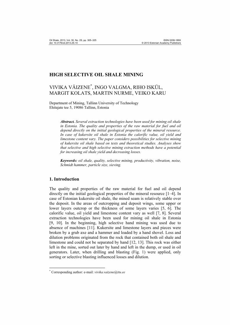
Fig. 1. Full seam drilling and blasting extraction method.
Both full seam and selective seam blasting were used. In case of under-
ground mining full seam and partial seam blasting were applied.
2. Tests
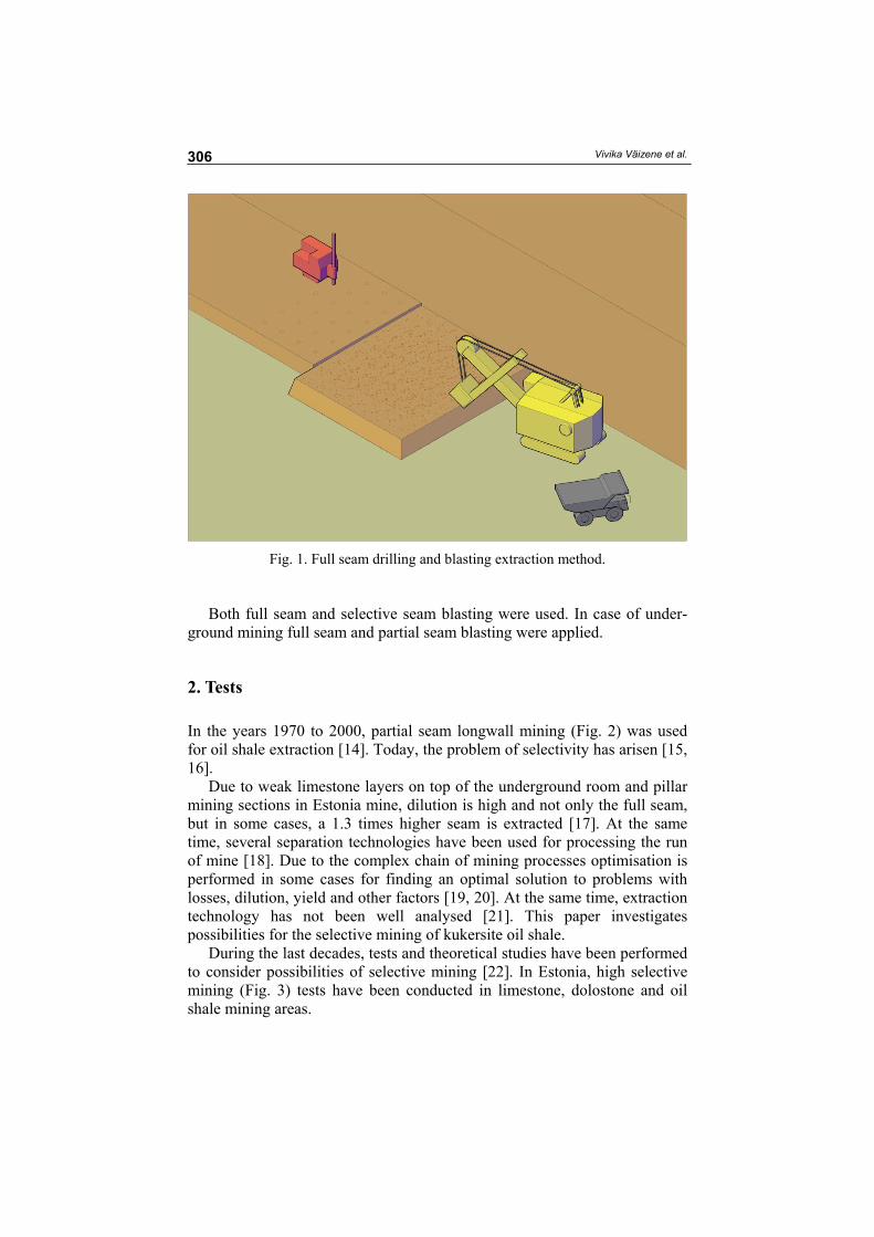
In the years 1970 to 2000, partial seam longwall mining (Fig. 2) was used for oil shale extraction [14]. Today, the problem of selectivity has arisen [15, 16].
Due to weak limestone layers on top of the underground room and pillar mining sections in Estonia mine, dilution is high and not only the full seam, but in some cases, a 1.3 times higher seam is extracted [17]. At the same time, several separation technologies have been used for processing the run of mine [18]. Due to the complex chain of mining processes optimisation is performed in some cases for finding an optimal solution to problems with losses, dilution, yield and other factors [19, 20]. At the same time, extraction technology has not been well analysed [21]. This paper investigates possibilities for the selective mining of kukersite oil shale.
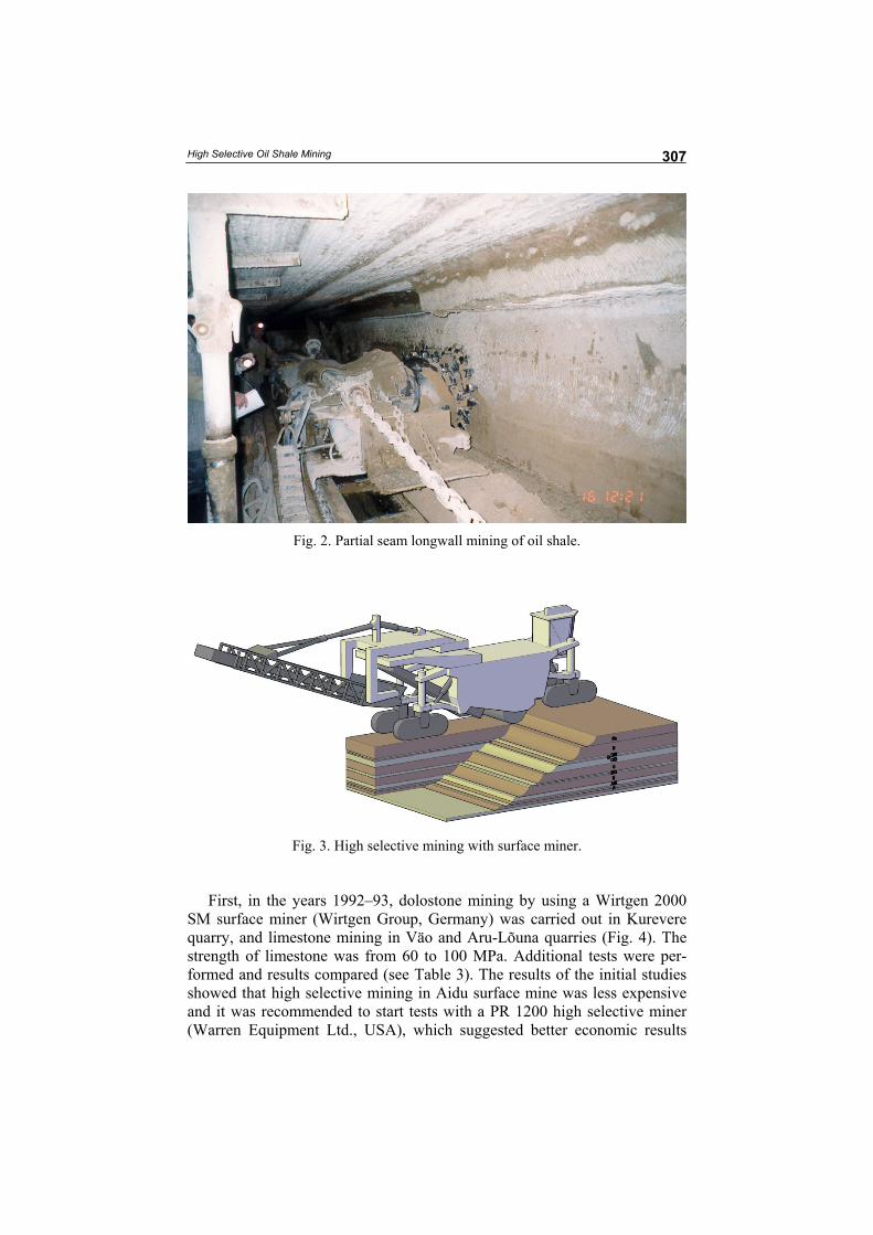
During the last decades, tests and theoretical studies have been performed to consider possibilities of selective mining [22]. In Estonia, high selective mining (Fig. 3) tests have been conducted in limestone, dolostone and oil shale mining areas.
High Selective Oil Shale Mining
307
Fig. 2. Partial seam longwall mining of oil shale.
Fig. 3. High selective mining with surface miner.
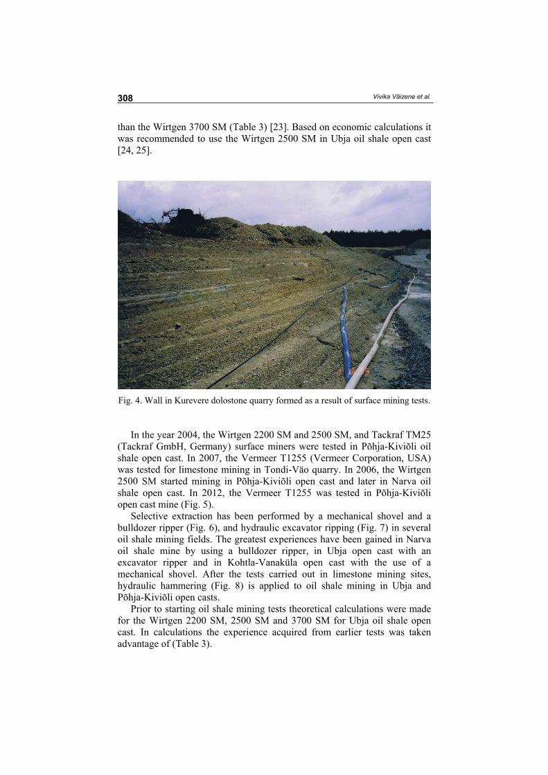
First, in the years 1992–93, dolostone mining by using a Wirtgen 2000
SM surface miner (Wirtgen Group, Germany) was carried out in Kurevere quarry, and limestone mining in Väo and Aru-Lõuna quarries (Fig. 4). The strength of limestone was from 60 to 100 MPa. Additional tests were per-formed and results compared (see Table 3). The results of the initial studies showed that high selective mining in Aidu surface mine was less expensive and it was recommended to start tests with a PR 1200 high selective miner (Warren Equipment Ltd., USA), which suggested better economic results
Vivika Väizene et al.
308
than the Wirtgen 3700 SM (Table 3) [23]. Based on economic calculations it was recommended to use the Wirtgen 2500 SM in Ubja oil shale open cast [24, 25].
Fig. 4. Wall in Kurevere dolostone quarry formed as a result of surface mining tests.
In the year 2004, the Wirtgen 2200 SM and 2500 SM, and Tackraf TM25
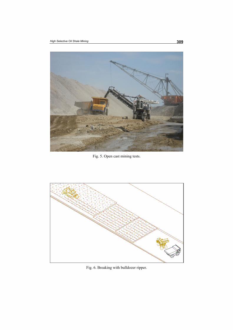
(Tackraf GmbH, Germany) surface miners were tested in Põhja-Kiviõli oil shale open cast. In 2007, the Vermeer T1255 (Vermeer Corporation, USA) was tested for limestone mining in Tondi-Väo quarry. In 2006, the Wirtgen 2500 SM started mining in Põhja-Kiviõli open cast and later in Narva oil shale open cast. In 2012, the Vermeer T1255 was tested in Põhja-Kiviõli open cast mine (Fig. 5).
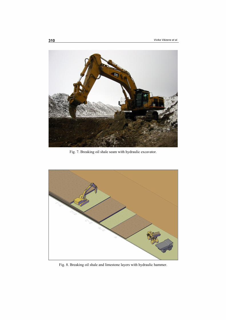
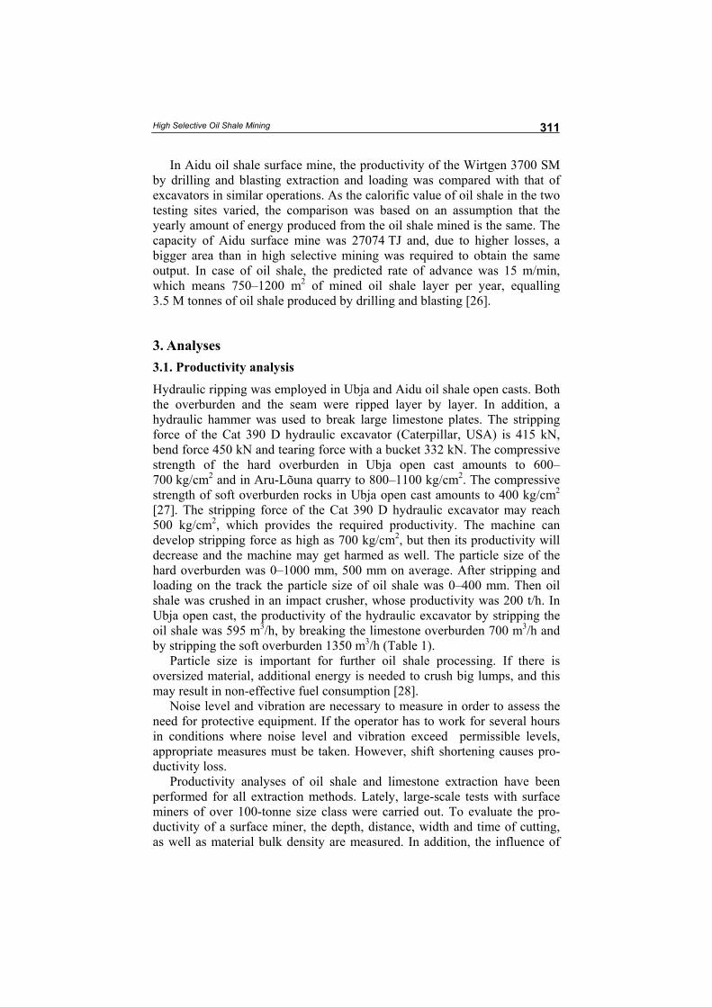
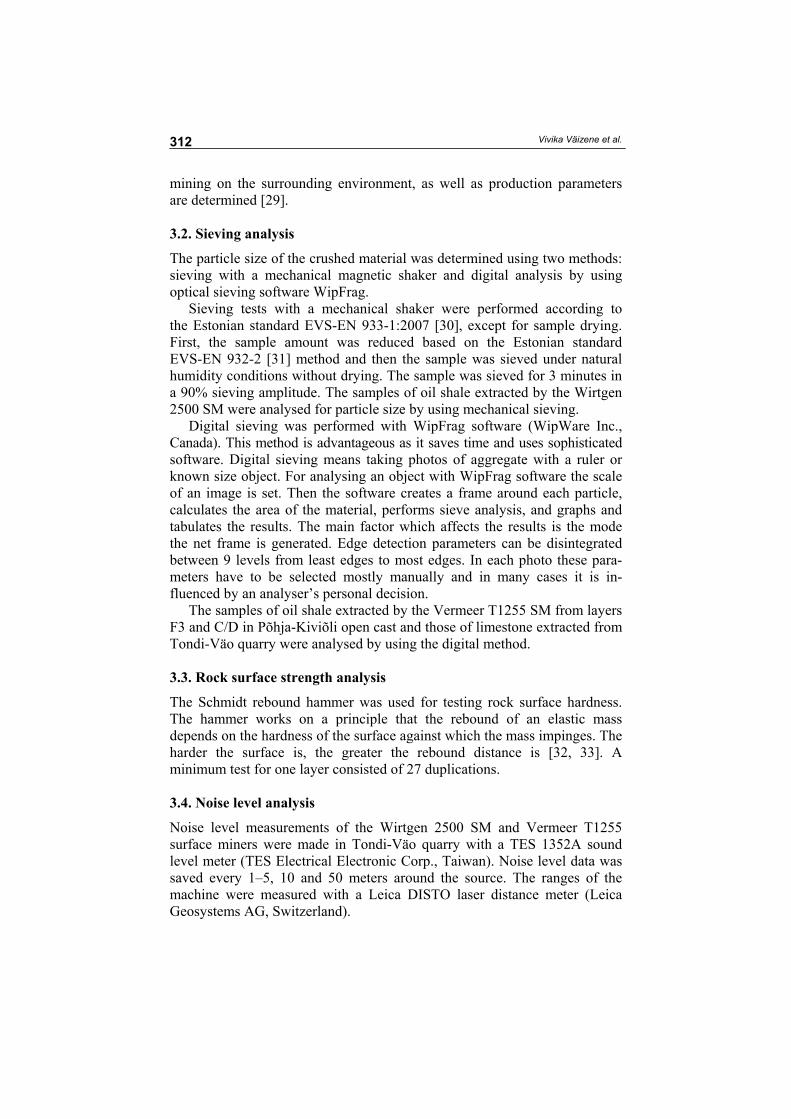
Selective extraction has been performed by a mechanical shovel and a bulldozer ripper (Fig. 6), and hydraulic excavator ripping (Fig. 7) in several oil shale mining fields. The greatest experiences have been gained in Narva oil shale mine by using a bulldozer ripper, in Ubja open cast with an excavator ripper and in Kohtla-Vanaküla open cast with the use of a mechanical shovel. After the tests carried out in limestone mining sites, hydraulic hammering (Fig. 8) is applied to oil shale mining in Ubja and Põhja-Kiviõli open casts.
Prior to starting oil shale mining tests theoretical calculations were made for the Wirtgen 2200 SM, 2500 SM and 3700 SM for Ubja oil shale open cast. In calculations the experience acquired from earlier tests was taken advantage of (Table 3).
High Selective Oil Shale Mining
309
Fig. 5. Open cast mining tests.
Fig. 6. Breaking with bulldozer ripper.
Vivika Väizene et al.
310
Fig. 7. Breaking oil shale seam with hydraulic excavator.
Fig. 8. Breaking oil shale and limestone layers with hydraulic hammer.
High Selective Oil Shale Mining
311
In Aidu oil shale surface mine, the productivity of the Wirtgen 3700 SM by drilling and blasting extraction and loading was compared with that of excavators in similar operations. As the calorific value of oil shale in the two testing sites varied, the comparison was based on an assumption that the yearly amount of energy produced from the oil shale mined is the same. The capacity of Aidu surface mine was 27074 TJ and, due to higher losses, a bigger area than in high selective mining was required to obtain the same output. In case of oil shale, the predicted rate of advance was 15 m/min, which means 750–1200 m2 of mined oil shale layer per year, equalling 3.5 M tonnes of oil shale produced by drilling and blasting [26].
3. Analyses 3.1. Productivity analysis
Hydraulic ripping was employed in Ubja and Aidu oil shale open casts. Both the overburden and the seam were ripped layer by layer. In addition, a hydraulic hammer was used to break large limestone plates. The stripping force of the Cat 390 D hydraulic excavator (Caterpillar, USA) is 415 kN, bend force 450 kN and tearing force with a bucket 332 kN. The compressive strength of the hard overburden in Ubja open cast amounts to 600–700 kg/cm2 and in Aru-Lõuna quarry to 800–1100 kg/cm2. The compressive strength of soft overburden rocks in Ubja open cast amounts to 400 kg/cm2 [27]. The stripping force of the Cat 390 D hydraulic excavator may reach 500 kg/cm2, which provides the required productivity. The machine can develop stripping force as high as 700 kg/cm2, but then its productivity will decrease and the machine may get harmed as well. The particle size of the hard overburden was 0–1000 mm, 500 mm on average. After stripping and loading on the track the particle size of oil shale was 0–400 mm. Then oil shale was crushed in an impact crusher, whose productivity was 200 t/h. In Ubja open cast, the productivity of the hydraulic excavator by stripping the oil shale was 595 m3/h, by breaking the limestone overburden 700 m3/h and by stripping the soft overburden 1350 m3/h (Table 1).
Particle size is important for further oil shale processing. If there is oversized material, additional energy is needed to crush big lumps, and this may result in non-effective fuel consumption [28].
Noise level and vibration are necessary to measure in order to assess the need for protective equipment. If the operator has to work for several hours in conditions where noise level and vibration exceed permissible levels, appropriate measures must be taken. However, shift shortening causes pro-ductivity loss.
Productivity analyses of oil shale and limestone extraction have been performed for all extraction methods. Lately, large-scale tests with surface miners of over 100-tonne size class were carried out. To evaluate the pro-ductivity of a surface miner, the depth, distance, width and time of cutting, as well as material bulk density are measured. In addition, the influence of
Vivika Väizene et al.
312
mining on the surrounding environment, as well as production parameters are determined [29].
3.2. Sieving analysis
The particle size of the crushed material was determined using two methods: sieving with a mechanical magnetic shaker and digital analysis by using optical sieving software WipFrag.
Sieving tests with a mechanical shaker were performed according to the Estonian standard EVS-EN 933-1:2007 [30], except for sample drying. First, the sample amount was reduced based on the Estonian standard EVS-EN 932-2 [31] method and then the sample was sieved under natural humidity conditions without drying. The sample was sieved for 3 minutes in a 90% sieving amplitude. The samples of oil shale extracted by the Wirtgen 2500 SM were analysed for particle size by using mechanical sieving.
Digital sieving was performed with WipFrag software (WipWare Inc., Canada). This method is advantageous as it saves time and uses sophisticated software. Digital sieving means taking photos of aggregate with a ruler or known size object. For analysing an object with WipFrag software the scale of an image is set. Then the software creates a frame around each particle, calculates the area of the material, performs sieve analysis, and graphs and tabulates the results. The main factor which affects the results is the mode the net frame is generated. Edge detection parameters can be disintegrated between 9 levels from least edges to most edges. In each photo these para-meters have to be selected mostly manually and in many cases it is in-fluenced by an analyser’s personal decision.
The samples of oil shale extracted by the Vermeer T1255 SM from layers F3 and C/D in Põhja-Kiviõli open cast and those of limestone extracted from Tondi-Väo quarry were analysed by using the digital method.
3.3. Rock surface strength analysis
The Schmidt rebound hammer was used for testing rock surface hardness. The hammer works on a principle that the rebound of an elastic mass depends on the hardness of the surface against which the mass impinges. The harder the surface is, the greater the rebound distance is [32, 33]. A minimum test for one layer consisted of 27 duplications. 3.4. Noise level analysis
Noise level measurements of the Wirtgen 2500 SM and Vermeer T1255 surface miners were made in Tondi-Väo quarry with a TES 1352A sound level meter (TES Electrical Electronic Corp., Taiwan). Noise level data was saved every 1–5, 10 and 50 meters around the source. The ranges of the machine were measured with a Leica DISTO laser distance meter (Leica Geosystems AG, Switzerland).
High Selective Oil Shale Mining
313
The cumulative noise impact of the Vermeer T1255 was recorded in Põhja-Kiviõli open cast with the TES 1254 sound level meter. Measurement points were located on top of a 31 m dump at a height of 1.5 m. Noise level was influenced by the work of two bulldozers (D375A and D155AX Komatsu; Komatsu America Corp., USA).
In the same open cast the operating parameters of the Wirtgen 2200 SM were determined. The positions were 5, 10 and 15 m from the source. The ranges of the machine were measured with a Leica DISTO laser distance meter.
All measurements were made in accordance with the regulation “Normal levels of noise in the living and recreation areas, residential and public buildings, and noise measurement techniques” [34–37].
3.5. Vibration analysis
Ground vibrations were measured with an ABEM Vibraloc vibration monitor (ABEM Instrument AB, Sweden) at a distance of 100, 13 and 5 m from surface miners [35, 36].
4. Results
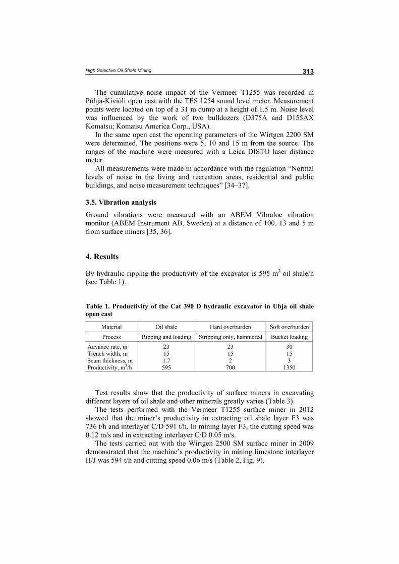
By hydraulic ripping the productivity of the excavator is 595 m3 oil shale/h (see Table 1).
Table 1. Productivity of the Cat 390 D hydraulic excavator in Ubja oil shale open cast
Material Oil shale Hard overburden Soft overburden
Process Ripping and loading Stripping only, hammered Bucket loading
Advance rate, m 23 23 30 Trench width, m 15 15 15 Seam thickness, m 1.7 2 3 Productivity, m3/h 595 700 1350
Test results show that the productivity of surface miners in excavating
different layers of oil shale and other minerals greatly varies (Table 3). The tests performed with the Vermeer T1255 surface miner in 2012
showed that the miner’s productivity in extracting oil shale layer F3 was 736 t/h and interlayer C/D 591 t/h. In mining layer F3, the cutting speed was 0.12 m/s and in extracting interlayer C/D 0.05 m/s.
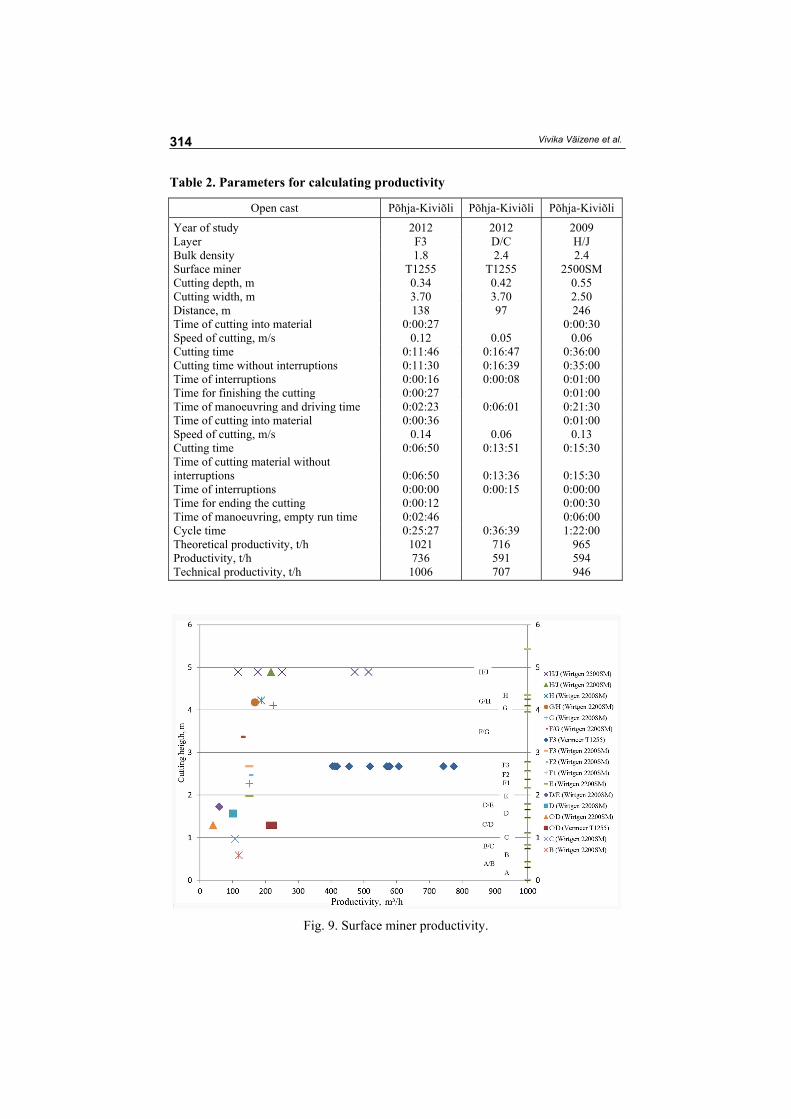
The tests carried out with the Wirtgen 2500 SM surface miner in 2009 demonstrated that the machine’s productivity in mining limestone interlayer H/J was 594 t/h and cutting speed 0.06 m/s (Table 2, Fig. 9).
Vivika Väizene et al.
314
Table 2. Parameters for calculating productivity
Open cast Põhja-Kiviõli Põhja-Kiviõli Põhja-Kiviõli
Year of study 2012 2012 2009 Layer F3 D/C H/J Bulk density 1.8 2.4 2.4 Surface miner T1255 T1255 2500SM Cutting depth, m 0.34 0.42 0.55 Cutting width, m 3.70 3.70 2.50 Distance, m 138 97 246 Time of cutting into material 0:00:27 0:00:30 Speed of cutting, m/s 0.12 0.05 0.06 Cutting time 0:11:46 0:16:47 0:36:00 Cutting time without interruptions 0:11:30 0:16:39 0:35:00 Time of interruptions 0:00:16 0:00:08 0:01:00 Time for finishing the cutting 0:00:27 0:01:00 Time of manoeuvring and driving time 0:02:23 0:06:01 0:21:30 Time of cutting into material 0:00:36 0:01:00 Speed of cutting, m/s 0.14 0.06 0.13 Cutting time 0:06:50 0:13:51 0:15:30 Time of cutting material without interruptions 0:06:50 0:13:36 0:15:30 Time of interruptions 0:00:00 0:00:15 0:00:00 Time for ending the cutting 0:00:12 0:00:30 Time of manoeuvring, empty run time 0:02:46 0:06:00 Cycle time 0:25:27 0:36:39 1:22:00 Theoretical productivity, t/h 1021 716 965 Productivity, t/h 736 591 594 Technical productivity, t/h 1006 707 946
Fig. 9. Surface miner productivity.
High Selective Oil Shale Mining
315
Table 3. Surface mining tests [38–42]
Period Machine type Machine t/h Mm3/y Site Mineral resource
1981 Surface miner 3000 SM 3,1 Rheinische Braun-kohlen, Germany
Lignite
Surface miner 3800 SM 6 Surface miner 2600 SM 1985 Surface miner 1900 SM 159 Beli Kamen, Serbia Limestone 1987 Surface miner 4200 SM/1600 3000 Thorley, Australia Coal Surface miner 4200 SM 2400 San Antonio,
Texas, USA Lignite
1986 Surface miner 3500 SM Texas, USA Limestone 1990 Surface miner 2600 SM Väo, Estonia Limestone 1996–1997 Surface miner 1900 SM India Limestone 1995–1997 Surface miner 2100 SM India Limestone
with clay 1996 Surface miner 2100 SM USA Marl 1996 Surface miner 2100 SM Estonia Limestone
and dolo-stone
1996 Surface miner 2100 SM Sweden Limestone and marl
1996 Surface miner 2100 SM England Limestone and dolo-stone
3000 SM 400 Collie Basin, Australia
Coal
2004 TM25 600 Põhja-Kiviõli, Estonia
Oil shale
2004 2200 SM + conveyor
312 Põhja-Kiviõli, Estonia
Oil shale
2004 2200 SM 500 Põhja-Kiviõli, Estonia
Oil shale
2004 2500 SM + conveyor
504 Põhja-Kiviõli, Estonia
Oil shale
2004 2500 SM 527 Põhja-Kiviõli, Estonia
Oil shale
4.1. Mechanical sieving
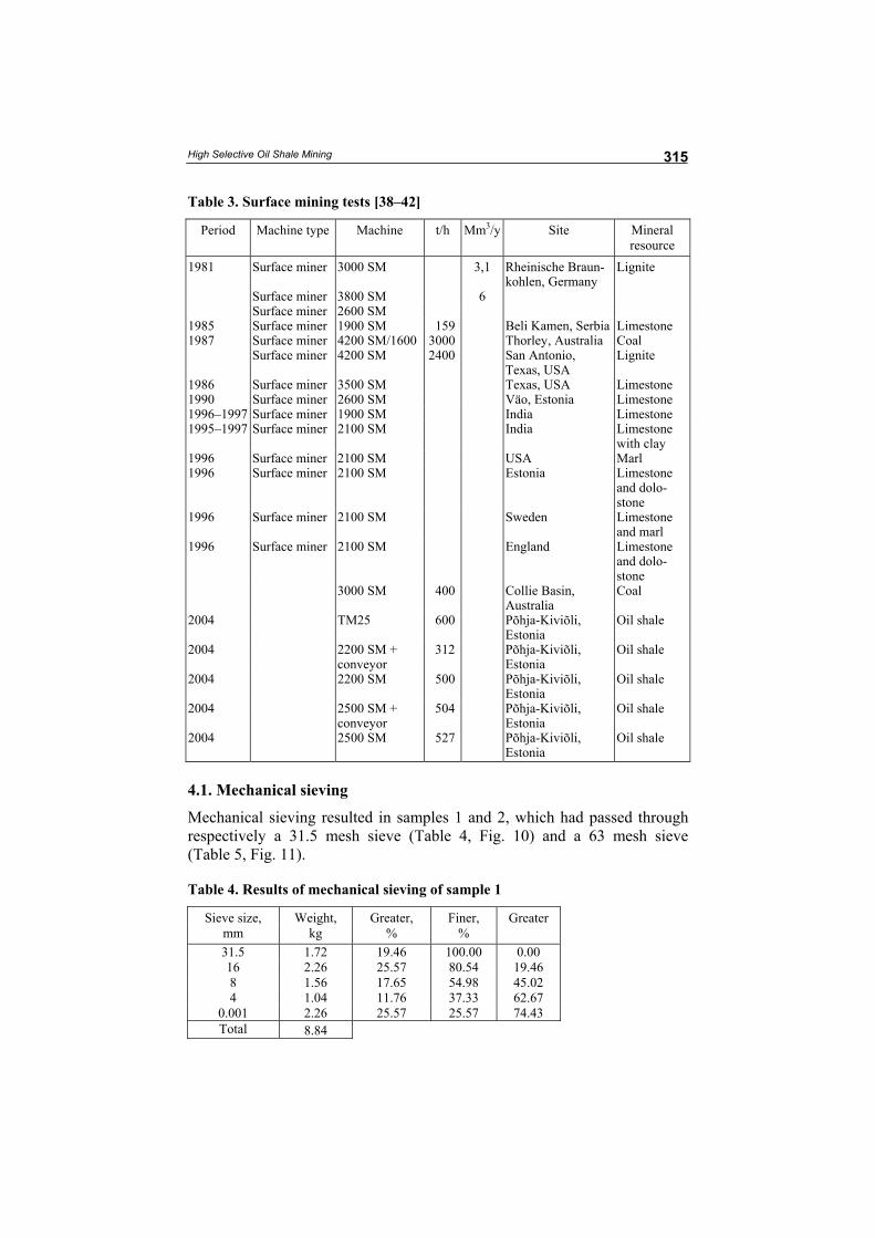
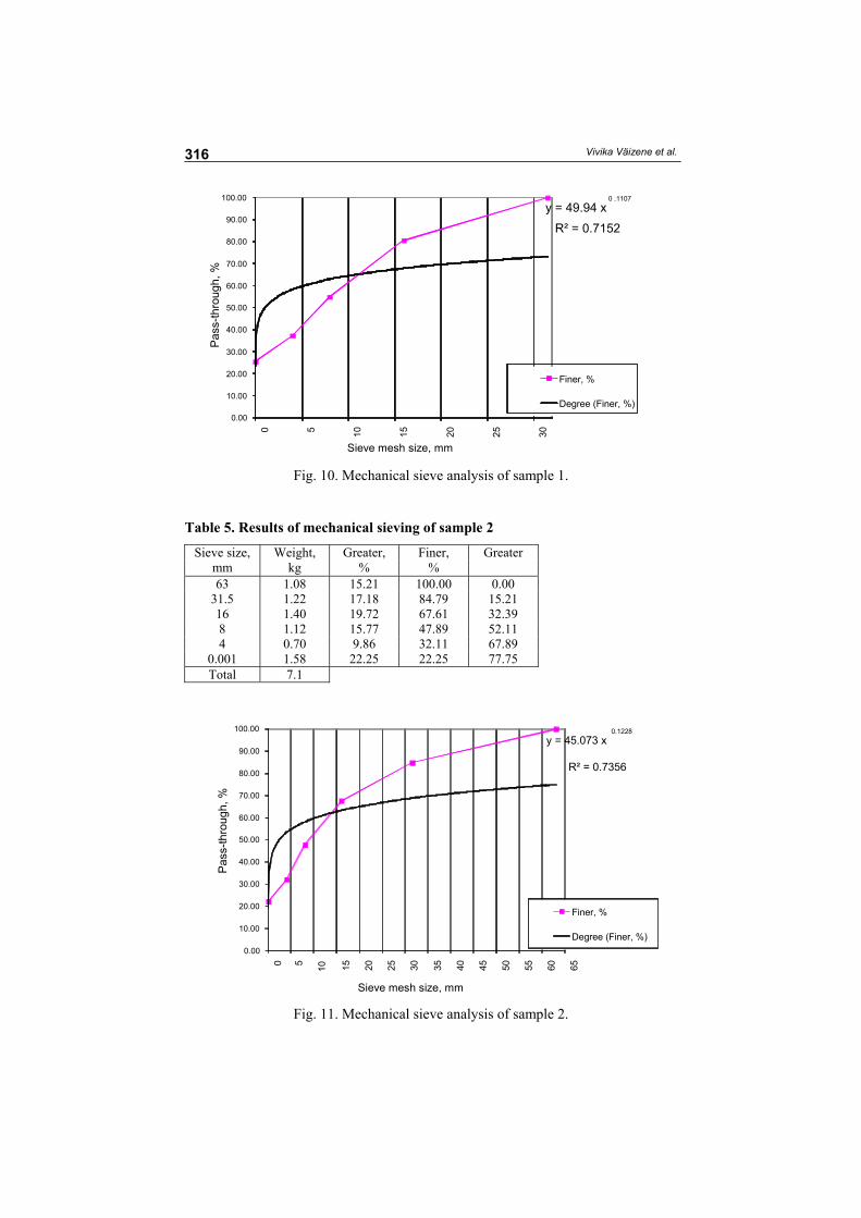
Mechanical sieving resulted in samples 1 and 2, which had passed through respectively a 31.5 mesh sieve (Table 4, Fig. 10) and a 63 mesh sieve (Table 5, Fig. 11).
Table 4. Results of mechanical sieving of sample 1
Sieve size, mm
Weight, kg
Greater, %
Finer, %
Greater
31.5 1.72 19.46 100.00 0.00 16 2.26 25.57 80.54 19.46 8 1.56 17.65 54.98 45.02 4 1.04 11.76 37.33 62.67
0.001 2.26 25.57 25.57 74.43 Total 8.84
Vivika Väizene et al.
316
y = 49.94 x0 .1107
R² = 0.7152
0.00 10.00 20.00 30.00 40.00 50.00 60.00 70.00 80.00 90.00
100.00
0 5 10
15
20
25
30
Sieve mesh size, mm
Finer, %
Degree (Finer, %)
Fig. 10. Mechanical sieve analysis of sample 1.
Table 5. Results of mechanical sieving of sample 2
Sieve size, mm
Weight, kg
Greater, %
Finer, %
Greater
63 1.08 15.21 100.00 0.00 31.5 1.22 17.18 84.79 15.21 16 1.40 19.72 67.61 32.39 8 1.12 15.77 47.89 52.11 4 0.70 9.86 32.11 67.89
0.001 1.58 22.25 22.25 77.75 Total 7.1
y = 45.073 x 0.1228
R² = 0.7356
0.00
10.00
20.00
30.00
40.00
50.00
60.00
70.00
80.00
90.00
100.00
0 5 10
15
20
25
30
35
40
45
50
55
60
65
Sieve mesh size, mm
Finer, %
Degree (Finer, %)
Fig. 11. Mechanical sieve analysis of sample 2.
Pas
s-th
roug
h, %
P
ass-
thro
ugh,
%
High Selective Oil Shale Mining
317
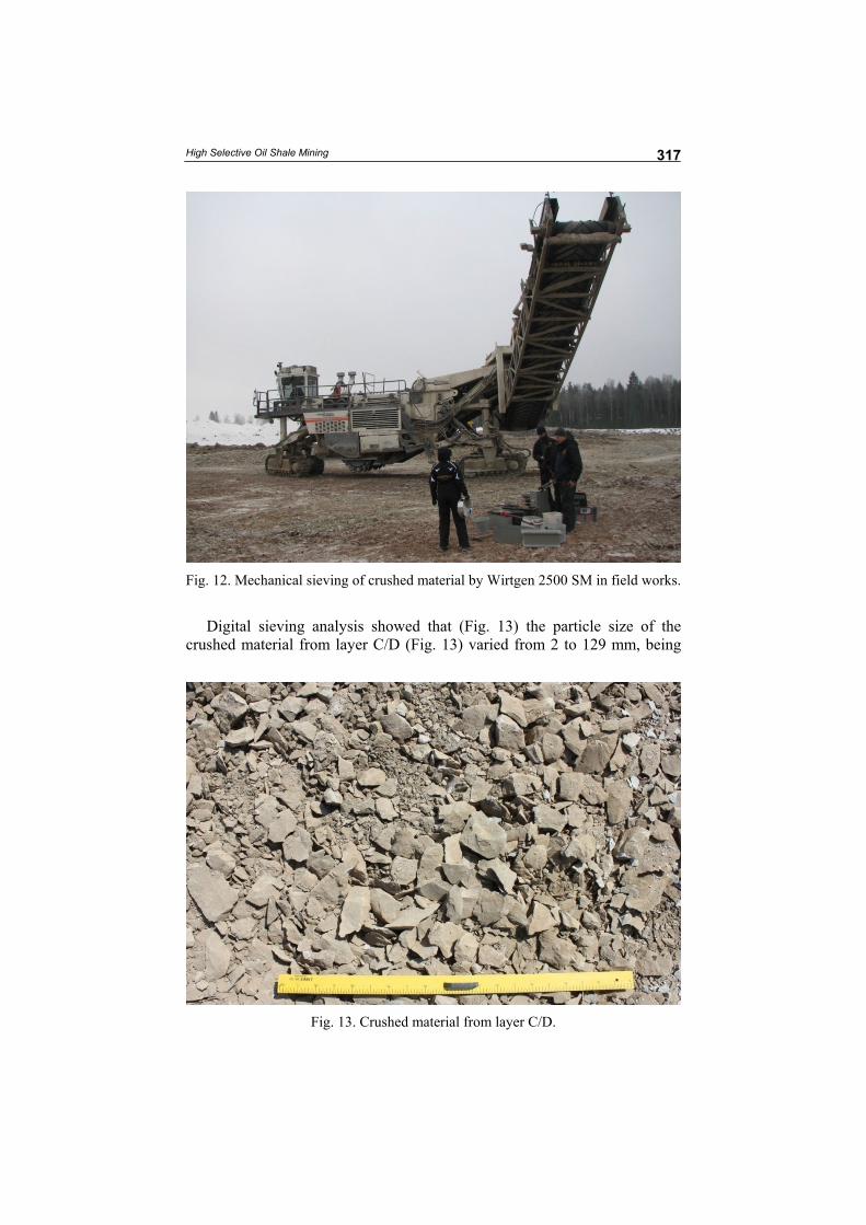
Fig. 12. Mechanical sieving of crushed material by Wirtgen 2500 SM in field works.
Digital sieving analysis showed that (Fig. 13) the particle size of the crushed material from layer C/D (Fig. 13) varied from 2 to 129 mm, being
Fig. 13. Crushed material from layer C/D.
Vivika Väizene et al.
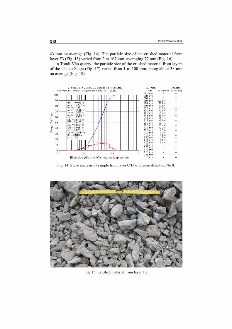
318
43 mm on average (Fig. 14). The particle size of the crushed material from layer F3 (Fig. 15) varied from 2 to 167 mm, averaging 77 mm (Fig. 16).
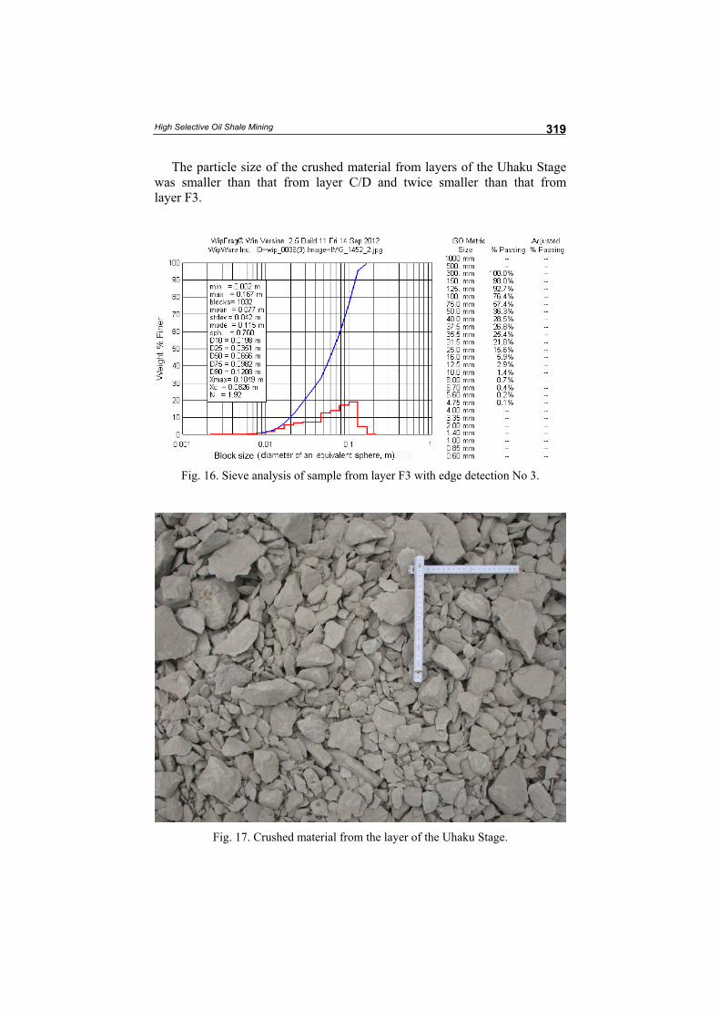
In Tondi-Väo quarry, the particle size of the crushed material from layers of the Uhaku Stage (Fig. 17) varied from 1 to 100 mm, being about 38 mm on average (Fig. 18).
Fig. 14. Sieve analysis of sample from layer C/D with edge detection No 8.
Fig. 15. Crushed material from layer F3.
High Selective Oil Shale Mining
319
The particle size of the crushed material from layers of the Uhaku Stage was smaller than that from layer C/D and twice smaller than that from layer F3.
Fig. 16. Sieve analysis of sample from layer F3 with edge detection No 3.
Fig. 17. Crushed material from the layer of the Uhaku Stage.
Vivika Väizene et al.
320
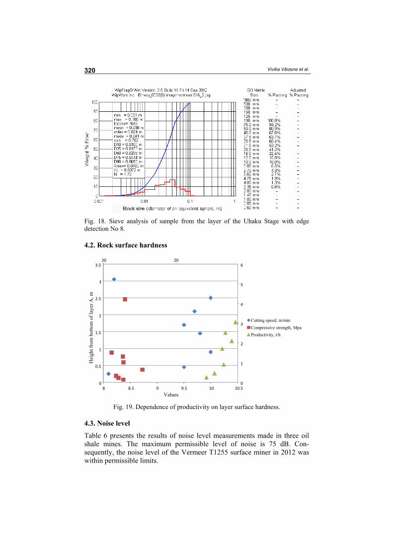
Fig. 18. Sieve analysis of sample from the layer of the Uhaku Stage with edge detection No 8. 4.2. Rock surface hardness
20 20
0
1
2
3
4
5
6
0
0.5
1
1.5
2
2.5
3
3.5
8 8.5 9 9.5 10 10.5Values
Cutting speed, m/min Compressive strength, Mpa Productivity, t/h
Fig. 19. Dependence of productivity on layer surface hardness. 4.3. Noise level
Table 6 presents the results of noise level measurements made in three oil shale mines. The maximum permissible level of noise is 75 dB. Con-sequently, the noise level of the Vermeer T1255 surface miner in 2012 was within permissible limits.
Hei
ght f
rom
bot
tom
of l
ayer
A, m
High Selective Oil Shale Mining
321
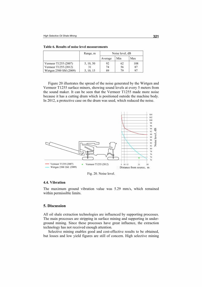
Table 6. Results of noise level measurements
Range, m Noise level, dB
Average Min Max Vermeer T1255 (2007) 5, 10, 50 92 62 108 Vermeer T1255 (2012) 31 74 56 87 Wirtgen 2500 SM (2009) 5, 10, 15 89 79 97
Figure 20 illustrates the spread of the noise generated by the Wirtgen and
Vermeer T1255 surface miners, showing sound levels at every 5 meters from the sound maker. It can be seen that the Vermeer T1255 made more noise because it has a cutting drum which is positioned outside the machine body. In 2012, a protective case on the drum was used, which reduced the noise.
Fig. 20. Noise level.
4.4. Vibration
The maximum ground vibration value was 5.29 mm/s, which remained within permissible limits.
5. Discussion
All oil shale extraction technologies are influenced by supporting processes. The main processes are stripping in surface mining and supporting in under-ground mining. Since these processes have great influence, the extraction technology has not received enough attention.
Selective mining enables good and cost-effective results to be obtained, but losses and low yield figures are still of concern. High selective mining
Vivika Väizene et al.
322
gives good results starting from 100-tonne miners. Vibration and noise are not limiting the usage of these technologies. The advantage of high selective mining is reduced oil shale losses. It is hypothesized that the production of low-class aggregate from the oil shale limestone overburden with high selective mining, without drilling and blasting and first stage crushing, is possible.
In the Estonian oil shale deposit, the hardness of limestone and oil shale layers does not influence the performance of surface miners, regardless of the direction of drum rotation. Surface hardness is a useful characteristic to predict the wear of surface miner teeth, as well as the machine’s productivity (Fig. 19).
6. Conclusion
It is recommended to use high selective and selective extraction in cases when the quality of oil shale is important. It is technologically possible.
Acknowledgement
This research is part of the studies under the Estonian Archimedes Founda-tion project “Doctoral School of Energy and Geotechnology II”, the European Union Baltic Sea project MIN-NOVATION, and the research project AR12007 “Sustainable and environmentally acceptable oil shale mining” in the framework of the Estonian National Energy Technology Program. REFERENCES
1. Valgma, I., Reinsalu, E., Sabanov, S., Karu, V. Quality control of oil shale production in Estonian mines. Oil Shale, 2010, 27(3), 239–249.
2. Valgma, I. Oil shale mining-related research in Estonia. Oil Shale, 2009, 26(4), 445–450.
3. Gulevitš, J., Bashkite, V., Iskül, R. Sustainable development of Estonian mineral resources for economical usage in roads construction. In: 9th Inter-national Symposium “Topical Problems in the Field of Electrical and Power Engineering” and “Doctoral School of Energy and Geotechnology II” (Laht-mets, R., ed.), Pärnu, Estonia, June 14–19, 2010. Tallinn University of Techno-logy, Tallinn, 2010, 77–82.
4. Valgma, I., Karu, V., Anapaio, A., Väizene, V. Increasing oil shale quality for meeting EU environmental requirements. Mining and the Environment. Freiberg TU, Baia Mare, 2007, 195–205.
5. Valgma, I. Estonian oil shale resources calculated by GIS method. Oil Shale, 2003, 20(3S), 404–411.
High Selective Oil Shale Mining
323
6. Valgma, I. An evaluation of technological overburden thickness limit of oil shale open casts by using draglines. Oil Shale, 1998, 15(2S), 134–146.
7. Reinsalu, E., Valgma, I. Oil shale resources for oil production. Oil Shale, 2007, 24(1), 9–14.
8. Koitmets, K., Reinsalu, E., Valgma, I. Precision of oil shale energy rating and oil shale resources. Oil Shale, 2003, 20(1), 15–24.
9. Valgma, I., Västrik, A., Kõpp, V. Sustainable mining technologies for Estonian minerals industry. In: 9th International Symposium “Topical Problems in the Field of Electrical and Power Engineering” and “Doctoral School of Energy and Geotechnology II” (Lahtmets, R., ed.), Pärnu, Estonia, June 14–19, 2010. Estonian Society of Moritz Hermann Jacobi, Tallinn, 2010, 69–73.
10. Valgma, I. Dependence of the mining advance rate on the mining technologies and their usage criteria. Resource Reproducing, Low-wasted and Environ-mentally Protecting Technologies of Development of the Earth Interior (Valgma, I., ed.). Department of Mining TUT; Peoples’ Friendship University of Russia, Tallinn, 2009, 2 pp.
11. Valgma, I. Map of oil shale mining history in Estonia. In: Proc. II. 5th Mining History Congress, Greece, Milos Conference Centre – George Eliopoulos, 2001. Agricola, 2001, 193–198.
12. Valgma, I., Kattel, T. Results of shallow mining in Estonia. In: EU Legislation as it Affects Mining: Proc. TAIEX Workshop in Tallinn: INFRA 22944 TAIEX Workshop, Tallinn, 30.11.–02.12.2006 (Valgma, I., Buhrow, Chr., eds.). Tallinn University of Technology, Tallinn, 2006, 118–125.
13. Valgma, I., Nikitin, O., Lohk, M. Oil shale mining development in Estonia. In: EU Legislation as it Affects Mining: Proc. TAIEX Workshop in Tallinn: INFRA 22944 TAIEX Workshop, Tallinn, 30.11.–02.12.2006 (Valgma, I., Buhrow, Chr., eds.). Tallinn University of Technology, Tallinn, 2006, 103–113.
14. Väizene, V. Backfilling technologies for oil shale mines. Resource Repro-ducing, Low-wasted and Environmentally Protecting Technologies of Develop-ment of the Earth Interior (Valgma, I., ed.). Department of Mining TUT; Peoples’ Friendship University of Russia, Tallinn, 2009, 1 pp.
15. Valgma, I., Tammeoja, T., Anepaio, A., Karu, V., Västrik, A. Underground mining challenges for Estonian oil shale deposit. Schacht, Strecke und Tunnel (Buhrow, Chr., Zuchowski, J., Haack, A., eds.). TU Bergakademie, Freiberg, 2008, 161–172.
16. Karu, V., Valgma, V., Västrik, A. Multi criterial modelling of oil shale mining fields. Mining and the Environment, Freiberg TU, Baia Mare, 2007 (225).
17. Valgma, I. Geographical Information System for Oil Shale Mining - MGIS. (PhD Thesis). Tallinn University of Technology Press, Tallinn, 2002.
18. Väli, E., Valgma, I., Reinsalu, E. Usage of Estonian oil shale. Oil Shale, 2008, 25(2S), 101–114.
19. Karu, V., Västrik, A., Anepaio, A., Väizene, V., Adamson, A., Valgma, I. Future of oil shale mining technology in Estonia. Oil Shale, 2008, 25(2S), 125–134.
20. Valgma, I., Karu, V., Västrik, A., Väizene, V. Future of oil shale mining. In: Georesources and public policy: research, management, environment. 15th
Meeting of the Association of European Geological Societies, 16–20.09.2007, Tallinn, Estonia (Hints, O., Kaljo, S., eds.), Eesti Geoloogia Selts, Tallinn, 2007, 81.
Vivika Väizene et al.
324
21. Valgma, I.; Karu, V. Mining in Estonia - a development towards the EU. In: EU Legislation as it Affects Mining: Proc. TAIEX Workshop in Tallinn: INFRA 22944 TAIEX Workshop, Tallinn, 30.11.–02.12.2006 (Valgma, I., Buhrow, Chr., eds.), Tallinn University of Technology, Tallinn, 2006, 98–102.
22. Valgma, I.; Kattel, T. Low depth mining in Estonian oil shale deposit - Abbau von Ölschiefer in Estland. In: Kolloquium Schacht, Strecke und Tunnel 2005: 14–15. April 2005, Freiberg/Sachsen. TU Bergakademie, Freiberg, 2005, 213–223.
23. Undusk, V. Feasibility and Technological Study for Wirtgen 3700 SM High-Selective Miner in Conditions of Aidu Oil Shale Open Cast. AS Estonian Oil Shale Applied Research Centre, Jõhvi, 1997 (in Estonian).
24. Iskül, R. Ubja Oil Shale Open Cast Development with High-Selective Miner and Ripper. Diploma thesis. Tallinn, 2001 (in Estonian).
25. Iskül, R. Solving problems related to the Ubja oil shale opencast mine, Estonia. Resource Reproducing, Low-wasted and Environmentally Protecting Techno-logies of Development of the Earth Interior (Valgma, I., ed.). Department of Mining TUT; Peoples’ Friendship University of Russia, Tallinn, 2009, 1 pp.
26. Evaluation of Aidu Oil Shale Open Cast as RAS Kiviter Base Material. AS Minerex, Tallinn, 1996 (in Estonian).
27. Valgma, I., Leiaru, M., Karu, V., Iskül, R. Sustainable mining conditions in Estonia. 11th International Symposium "Topical Problems in the Field of Electrical and Power Engineering", Doctoral School of Energy and Geo-technology, Pärnu, Estonia, 16–21.01.2012. Tallinn: Elektriajam, 2012, 229–238.
28. Väli, E. Analysis of oil shale high-selective mining with surface miner in Estonia. Oil Shale, 2011, 28(1), 49–57.
29. Robam, K., Väizene, V., Anepaio, A., Kolats, M., Valgma, I. Measuring mining influence in the form of students practice in opposition to the emotional environmental impact assessment. In: 5th International Symposium "Topical problems in the field of electrical and power engineering". Doctoral school of energy and geotechnology (Lahtmets, R., ed.). Tallinn University of Techno-logy, Tallinn, 2008, 62–65.
30. Estonian standard EVS-EN 933-1:2007. Tests for geometrical properties of aggregates. Part 1: Determination of particle size distribution. Sieving method.
31. Estonian standard EVS-EN 933-1:2007. Tests for geometrical properties of aggregates. Part 1: Determination of particle size distribution. Sieving method.
32. Schmidt Rebound Hammer Test. http://civil-online2010.blogspot.com/2010/09/ schmidt-rebound-hammer-test.html [05.09.2012].
33. Schmidt Concrete Test Hammer. Surface Hardness and Penetration Resistance. http://www.mastrad.com/schmidt.htm [05.09.2012].
34. Normal levels of noise in the living and recreation areas, residential and public buildings, and noise measurement techniques. Regulation of the Minister of Social Affairs. RTL 2002, 38, 511.
35. Surface Miner Vermeer T1255 Productivity and Environmental Impact Assess-ment in Tondi-Väo limestone Quarry. TUT Department of Mining, 2007, 13–17.
36. Surface Miner Vermeer T1255 Testing in Põhja-Kiviõli Oil Shale Open Cast. TUT Department of Mining, 2012, 9-10.
37. GPS Mapping at Põhja-Kiviõli Oil Shale Open Cast and Chemical Analyses of Water and Flow. TUT Department of Mining, 2008.
High Selective Oil Shale Mining
325
38. Väli, E. Best Available Technology for the Environmentally Friendly Mining with Surface Miner. PhD Thesis. TUT press, 2010.
39. Wirtgen Continuous Surface Mining. Wirtgen GmbH, 1987. 40. The New Opencast Mining Technology and Its Economics. Wirtgen GmbH,
1987. 41. Mining Equipment. New mining equipment – Surface Miner. Krupp Industrie-
technik, 1989. 42. Adamson, A., Jostov, M., Kattel. Perspectives for the mining of oil shale and
limestone with surface miner in Estonia. In: Proc. 8th International Symposium Continuous Surface Mining, Aachen, Germany, 24–27.09.2006. Verlagshaus Mainz GmbH Aachen, Aachen, Germany, 2006. http://www.ene.ttu.ee/ maeinstituut/cutting06/overview.pdf
Received October 25, 2012