Embed Size (px)
Citation preview

High Speed Data Connector System
RosenbergerHSD® Connectors
AUTOMOTIVE

2
Rosenberger Automotive – a Synonym for Quality and Innovation
On the following pages we present the high-quality RosenbergerHSD® connectors developed in our Automotive Business Area. They fulfill the tough requirements of the automotive industry.
3Rosenberger Hochfrequenztechnik GmbH & Co. KG | www.rosenberger.com
The Rosenberger Online Catalog contains the current Rosen-bergerHSD® product range with specific details, including data sheets, assembly instructions, and panel piercings.
www.rosenberger.com/ok/hsd
Rosenberger Global Network 04
Quality & Environment 06
Competencies & Technology 08
Research & Development 10
Rosenberger Automotive 12
RosenbergerHSD® Product Overview 14
RosenbergerHSD® Number Codes 16
RosenbergerHSD® Codings 18
RosenbergerHSD® Technical Data 24
RosenbergerHSD® Connectors 26PCB Connectors – Wave Soldering 26PCB Connectors – Pin-in-Paste 27Cable Connectors 30Cable Connectors – Waterproof 32
RosenbergerHSD®+ Power Pin Connectors 33
RosenbergerHSD®e Technical Data 36
RosenbergerHSD®e Connectors 38Cable Connectors 38Waterproof Connectors 39
Test Components & Tools 40
Cable Assemblies 42
Technical References 54
Index 86
Contents

4
Rosenberger Global Network
Rosenberger is one of the world`s leading manufacturers of impedance controlled and optical connectivity solutions. It provides connectivity solutions in high-frequency, high-voltage, and fiber-optic technology for mobile commu-nication networks, data centers, test & measurement applications, automotive electronics, as well as high-voltage contact systems, medical electronics or aerospace engineering.
A global network of R&D, manufacturing and assembly locations provides innovation, optimized cost structure and excellent customer services world-wide – approx. 8,500 employees develop, produce and sell our products.
Contacts Automotive
Headquarters
Rosenberger Hochfrequenztechnik GmbH & Co. KGHauptstraße 1 | 83413 FridolfingP.O. Box 1260 | 84526 Tittmoning GermanyPhone +49 8684 [email protected]
Sales AutomotiveEuropeGermanyRosenberger Hochfrequenztechnik GmbH & Co. KGHauptstraße 183413 FridolfingGermanyPhone + [email protected]
FranceRosenberger Automotive FranceActipark17, Rue des Frères Lumière67201 EckbolsheimFrancePhone + 33-3-90 20 76 03Fax + 33-3-90 20 76 [email protected]
ItalyRosenberger Italia SrlVia Torri Bianche 7 - Piano 720871 Vimercate (MI)ItalyPhone + 39-039-96 [email protected]
SpainRosenberger Telecom, S.A.C/Lozoya n°2, nave 18 - P.l. Ventorro del Cano28925 Alcorcón - MadridSpainPhone + 34 91 352 8352Fax + 34 91 352 [email protected]
SwedenRosenberger Sverige ABVallgatan 5B17067 SolnaSwedenPhone + 46-8-6 36 26 00Fax + 46-8-6 36 26 [email protected]
United KingdomRosenberger UK Ltd.York House, Cottingley Business ParkBradford, BD16 1PEEnglandUnited KingdomPhone + 44-7980 [email protected]
North AmericaUSARosenberger Automotive USA 15900 Michigan Ave, Suite 5Dearborn, MI 48126United States of AmericaPhone + 1-734-673 4131Phone + 1-248-259 [email protected]

5Rosenberger Hochfrequenztechnik GmbH & Co. KG | www.rosenberger.com
South AmericaBrazilRosenberger Domex Telecom Ltda.Cabletech Avenue, 601GuamirimCEP 12295-230BR-Cacapava - São PauloBrazilPhone + 55-12-3221 8500Fax + 55-12-3221 [email protected]
ChileRosenberger Sudamérica Ltda.Aldunate 1961,Santiago 836-1195ChilePhone + 56-2-3 67 11 70Fax + 56-2-3 67 12 [email protected]
AsiaChina, Asia, AustraliaRosenberger Asia Pacific Electronic Co., Ltd.No. 3, Anxiang Road, Block BTianzhu Airport Industrial ZoneBeijing 101300PR ChinaPhone + 86-10-80 48 19 95Fax + 86-10-80 48 24 [email protected]
JapanRosenberger Automotive Japan, LLC.Sanno Mori Building 2-10-1 Nagata-Cho, Chiyoda-Ku100-0014 TokyoJapanPhone + 813 5511 [email protected]
KoreaRosenberger Automotive Korea#307/104, Gwang-Gyo Eduhiem, 904-1, Iui-Dong, Yeong Tong-guSuwon-si Gyeonggi-do (441-813)KoreaPhone + 82 70 7779 2236Mobile + 82 10 4729 [email protected]
IndiaRosenberger Electronic Co. (India) PvtLimitedPlot No. 263, Sector 6IMT Manesar, GurgaonHaryana-122050IndiaPhone + 91-124-477 55 00Fax + 91-124-477 55 [email protected]
The Rosenberger headquarters, located in Fridolfing in the southeast part of Bavaria, Germany, is the global center for our activities.
Rosenberger Global Network

6
Quality & Environment
The quality of our products, solutions and services is an essential part of our corporate strategy.
Ensuring the optimum quality of products and services and taking responsibility for our environment are funda-mental elements of Rosenberger's corporate philosophy. Our quality philosophy does not just cover the optimi-zation of parts and products, but also the continuous improvement of all company processes: from product development, planning, procurement, production, sales, logistics right through to environmental policy. To summa-rize, we want to offer maximum benefits for our customers all over the world.
We aim to act in an environmentally conscious manner, use materials economically, protect natural resources, recycle, and ensure energy efficiency.
As we have continuously improved our processes and consistently applied our quality management systems, we have been awarded many certificates.
Rosenberger has won a number of prestigious quality awards and prizes from several renowned customers and organizations for implementing its quality and environ-mental objectives.
IMDS SystemRosenberger is registered with the IMDS system (Inter-nationales MaterialDatenSystem der Automobilindustrie) since 2001. The products are fed systematically into the IMDS system.
www.mdsystem.com

7Rosenberger Hochfrequenztechnik GmbH & Co. KG | www.rosenberger.com
Certificates ISO/TS 16949 DIN EN 9100 ISO 9001 ISO 14001 DaKKs accreditation according to DIN EN ISO 17025
Quality & Environment

8
Competencies & Technology
Rosenberger's mission is to be a leader when it comes to innovation and technology within its business segments.
The ongoing focus on cost management and process optimization complements our commitment to the in-creasingly stringent requirements for delivering products of the highest quality. Effective research & development, the very latest manufacturing technologies, the highest possible levels of efficiency in production processes, and continuous improvement of process automation make up Rosenberger`s core competencies.

9Rosenberger Hochfrequenztechnik GmbH & Co. KG | www.rosenberger.com
Research & DevelopmentScience-based high frequency know-how enables us to continuously improve existing products and to design innovative products and solutions whether standard or customer specific. Numerous patents are proof of Rosenberger’s leadership as a creative and innovative partner.
ProductionBy manufacturing everything in house and using state of-the-art manufacturing technologies, Rosenberger can continue to develop and optimize key manufacturing tech-nologies – turned parts production, stamped & formed technology, injection molding technology. Manufacturing everything in house ensures a high degree of flexibility, and continuous quality controls, and means that newly designed products can be produced in the required quantities.
Plating TechnologyOur components can be electroplated quickly and flexibly in our own in-house electroplating facilities, regardless of whether this is to provide corrosion protection, optimized conductivity, or other technical and physical characteris-tics. Environmental protection is another key factor which must be taken into account when coating surfaces.
AssemblyRosenberger operates manufacturing and assembly locations around the world – fully automated assembly centers and customer-oriented cable assembly locations offer global support and local sourcing.
Injection MoldingWe use the very latest machinery and methods, as well as special materials and components to ensure the precision and durability of our tools and products. Rosenberger is able to process all available high-performance plastics.
Competencies & Technology

10
EMC and RF DesignThe increasing amount of electrical systems in hybrid and/or self-driven-vehicles increases the probability that electrical currents will interact with one another. To reduce unwanted effects, such as a high bit error rate, good shielding is needed. In addition, in unshielded systems with differential transmission technology, EMC is even more important. Furthermore, even if your transmission line is unaffected by the environment, the loss of signal quality caused by reflections or cable attenuation has to be minimized.
To analyze the transmission behavior, FEM and circuit simulation tools are used. Different system parameters, such as characteristic impedance, transmission and reflection coefficient, crosstalk and screening attenuation can be determined and optimized by simulation.
As a result, high frequency signals with high signal-to- noise ratio and high transmission form the basis for implementing efficient modulation schemes for ever- increasing data rates.
Mechanical and Thermal DesignDue to strict safety standards for hybrid/electrical engines and autonomous driving, the mechanical and thermal requirements have increased considerably in recent years.
Mechanical FEM calculations are performed for high retention forces or high coding efficiency at the connec-tor plastic housing. Investigations into the physics of an electrical contact (e.g., electrical resistance or fretting) en-able us to design contact springs with optimized contact forces and an electrically stable contact resistance over their entire lifetime, taking into account all tolerances, for example.
Knowledge about the resistance of a contact is the key when it comes to to simulating power loss and heating the contact system. This makes is possible to achieve mechanical robustness, high efficiency, and minimal heating of the connector even quicker.
11Rosenberger Hochfrequenztechnik GmbH & Co. KG | www.rosenberger.com
Research & Development
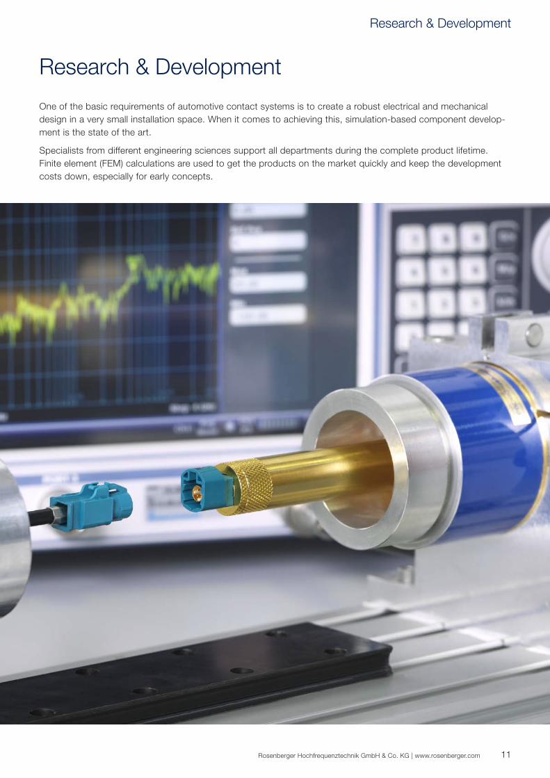
One of the basic requirements of automotive contact systems is to create a robust electrical and mechanical design in a very small installation space. When it comes to achieving this, simulation-based component develop-ment is the state of the art.
Specialists from different engineering sciences support all departments during the complete product lifetime. Finite element (FEM) calculations are used to get the products on the market quickly and keep the development costs down, especially for early concepts.
Research & Development

12
Rosenberger Automotive
At Rosenberger, we firmly believe in developing technology for the future. We are currently working on products and solutions that will shape our lives in the future.
We want to get faster and smarter in what we do and how we do it. Car driver assistance systems, connected car technology, electromobility, infotainment systems – Rosenberger is extremely committed to designing innova-tive connector systems for future automotive electronics.

13Rosenberger Hochfrequenztechnik GmbH & Co. KG | www.rosenberger.com
In 2000, Rosenberger started working in the automotive sector, designing and producing customized and standard products for these specific markets.
Rosenberger Automotive is a specialist development partner when it comes to integrating connector designs and customer-specific solutions with the highest qual-ity and best performance – while continuing to meet customer price targets.
The contact systems have been specially designed to fulfill the tough requirements of the automotive industry. From the beginning, Rosenberger has developed a close and open relationship with its customers.
The priority in the most automotive applications, such as autonomous driving and driver assistance systems, is to ensure safety. It is necessary to determine exact positions, continuously calculate routes, and detect and classify objects. High data volumes from several cameras, various sensors, and navigation sources must be combined and transported for this purpose – in real time.
Application Areas Autonomous Driving Driver Assistance Systems Navigation Infotainment Fond-Entertainment Internet & Mobile Communication Next Generation WLAN: "WiGig" (Wireless Gigabit)
Rosenberger Automotive
14
RosenbergerHSD® Product Overview
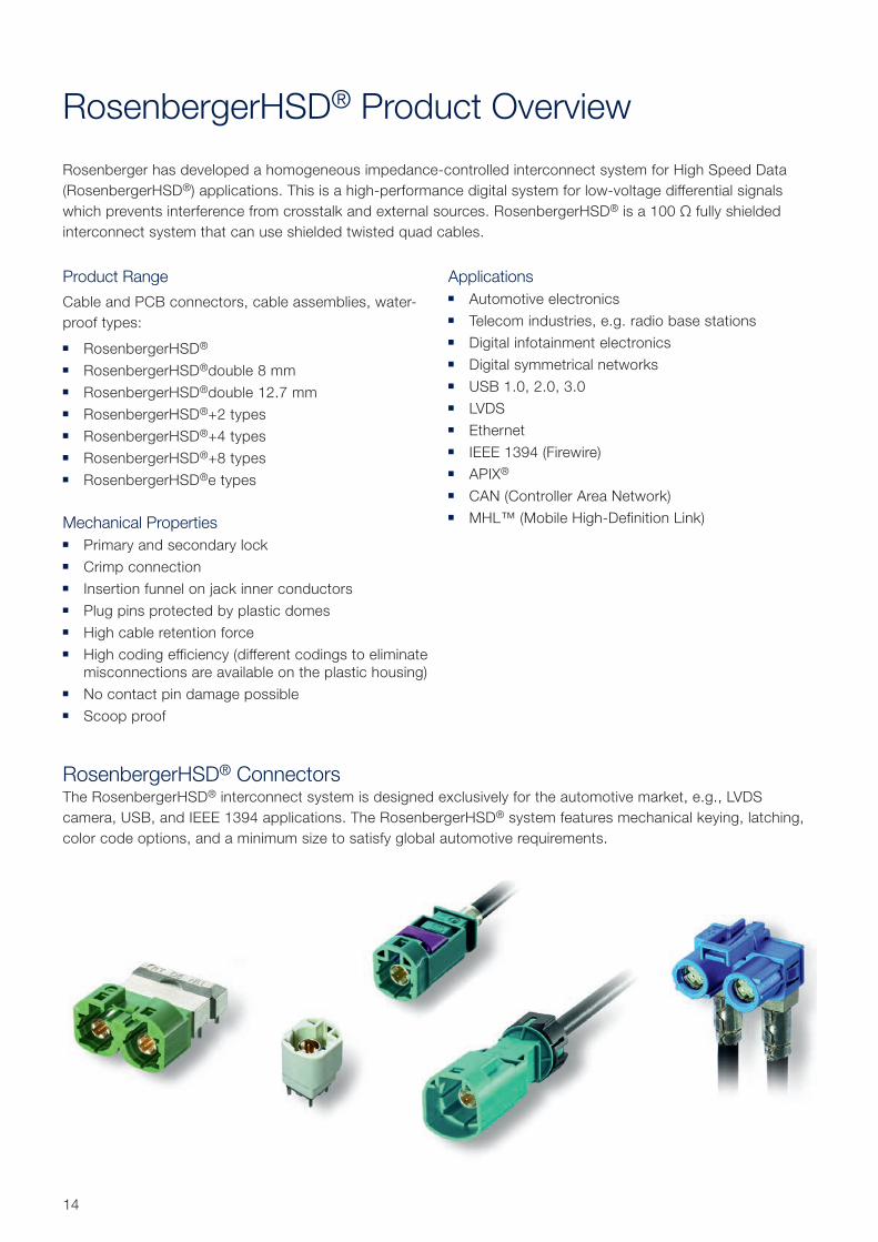
Rosenberger has developed a homogeneous impedance-controlled interconnect system for High Speed Data (RosenbergerHSD®) applications. This is a high-performance digital system for low-voltage differential signals which prevents interference from crosstalk and external sources. RosenbergerHSD® is a 100 Ω fully shielded interconnect system that can use shielded twisted quad cables.
RosenbergerHSD® ConnectorsThe RosenbergerHSD® interconnect system is designed exclusively for the automotive market, e.g., LVDS camera, USB, and IEEE 1394 applications. The RosenbergerHSD® system features mechanical keying, latching, color code options, and a minimum size to satisfy global automotive requirements.
Product Range
Cable and PCB connectors, cable assemblies, water-proof types:
RosenbergerHSD®
RosenbergerHSD®double 8 mm RosenbergerHSD®double 12.7 mm RosenbergerHSD®+2 types RosenbergerHSD®+4 types RosenbergerHSD®+8 types RosenbergerHSD®e types
Mechanical Properties Primary and secondary lock Crimp connection Insertion funnel on jack inner conductors Plug pins protected by plastic domes High cable retention force High coding efficiency (different codings to eliminate
misconnections are available on the plastic housing) No contact pin damage possible Scoop proof
Applications Automotive electronics Telecom industries, e.g. radio base stations Digital infotainment electronics Digital symmetrical networks USB 1.0, 2.0, 3.0 LVDS Ethernet IEEE 1394 (Firewire) APIX®
CAN (Controller Area Network) MHL™ (Mobile High-Definition Link)
15Rosenberger Hochfrequenztechnik GmbH & Co. KG | www.rosenberger.com
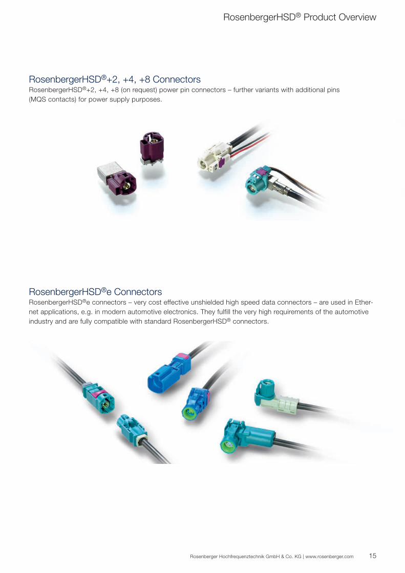
RosenbergerHSD®e ConnectorsRosenbergerHSD®e connectors – very cost effective unshielded high speed data connectors – are used in Ether-net applications, e.g. in modern automotive electronics. They fulfill the very high requirements of the automotive industry and are fully compatible with standard RosenbergerHSD® connectors.
RosenbergerHSD®+2, +4, +8 ConnectorsRosenbergerHSD®+2, +4, +8 (on request) power pin connectors – further variants with additional pins (MQS contacts) for power supply purposes.
RosenbergerHSD® Product Overview
16
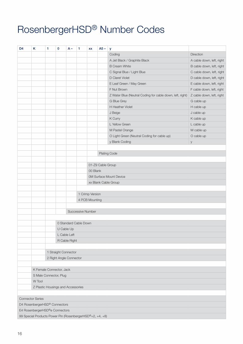
RosenbergerHSD® Number Codes
D4 K 1 0 A – 1 xx A5 – y
Coding Direction
A Jet Black / Graphite Black A cable down, left, right
B Cream White B cable down, left, right
C Signal Blue / Light Blue C cable down, left, right
D Claret Violet D cable down, left, right
E Leaf Green / May Green E cable down, left, right
F Nut Brown F cable down, left, right
Z Water Blue (Neutral Coding for cable down, left, right) Z cable down, left, right
G Blue Grey G cable up
H Heather Violet H cable up
J Beige J cable up
K Curry K cable up
L Yellow Green L cable up
M Pastel Orange M cable up
O Light Green (Neutral Coding for cable up) O cable up
y Blank Coding y
Plating Code
01-Z9 Cable Group
00 Blank
0M Surface Mount Device
xx Blank Cable Group
1 Crimp Version
4 PCB Mounting
Successive Number
0 Standard Cable Down
U Cable Up
L Cable Left
R Cable Right
1 Straight Connector
2 Right Angle Connector
K Female Connector, Jack
S Male Connector, Plug
W Tool
Z Plastic Housings and Accessories
Connector Series
D4 RosenbergerHSD® Connectors
E4 RosenbergerHSD®e Connectors
99 Special Products Power Pin (RosenbergerHSD®+2, +4, +8)

17Rosenberger Hochfrequenztechnik GmbH & Co. KG | www.rosenberger.com
RosenbergerHSD® Plating Code
RosenbergerHSD® Cable GroupsCable Group Impedance Cable Type
D5 100 Ω e.g. G&G K6750, X6656, LEONI Dacar® 535, 535-2, 636, 636-2
AF 90 ± 15 Ω e.g. G&G X6238, LEONI Dacar® 566
Outer ContactCode Plating Symbol Layer thickness Magnetic properties
A Nickel Ni 3.00 µm
L AuroDur® Au 0.15 µm non magnetic
X no plating, no outer contact for unshielded RosenbergerHSD®e
Center ContactCode Plating Symbol Layer thickness Magnetic properties
5 AuroDur® Au 0.15 µm non magnetic
RosenbergerHSD®e Cable GroupCable Group Impedance Cable Type
AK 100 Ω e.g. G&G X7622, LEONI Dacar® 625, unshielded
The used platings of outer and center contacts of Rosenberger connectors can be identified by each part number.
Example: D4S20L-40MA5-y Plating outer contact: Nickel (A) Plating center contact: AuroDur® (5)
AuroDur® – the Rosenberger Standard Plating for Gold SurfacesAuroDur® plating is the standard gold surface for all Rosenberger connector series.
AuroDur® has been developed by the engineering and metallurgical team at Rosenberger, well-experienced in developing electroplating standard and customized surfaces.
The AuroDur® surface consists of a thin gold layer on a non magnetic, chemically deposited layer of nickel: min. 2 µm Ni, 0.15 µm Au AuroDur® gold plating fully satisfies the high mechanical and electrical demands of radio frequency connectors. In contrast to conventional platings, essential characteristics are improved.
Properties: high abrasion and corrosion resistance excellent intermodulation low contact resistance very good solderability optimal distribution of layer thickness RoHS conform
RosenbergerHSD® Number Codes
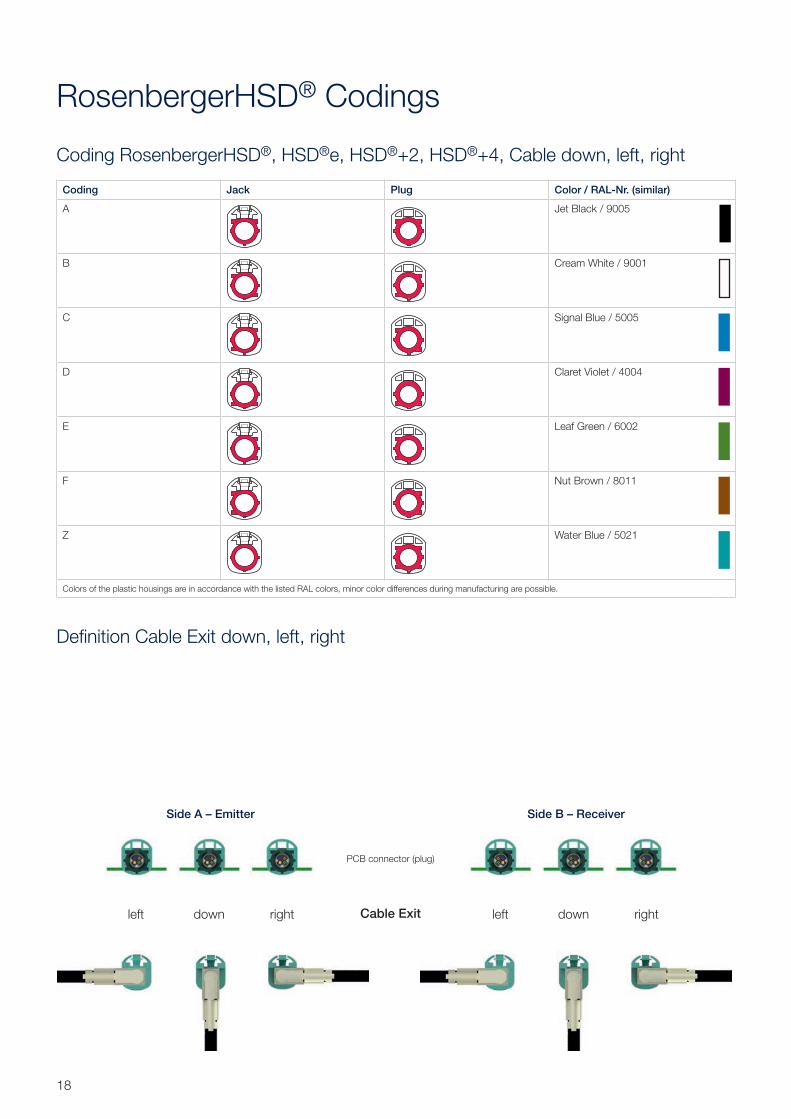
Coding Jack Plug Color / RAL-Nr. (similar)
A Jet Black / 9005
B Cream White / 9001
C Signal Blue / 5005
D Claret Violet / 4004
E Leaf Green / 6002
F Nut Brown / 8011
Z Water Blue / 5021
Colors of the plastic housings are in accordance with the listed RAL colors, minor color differences during manufacturing are possible.
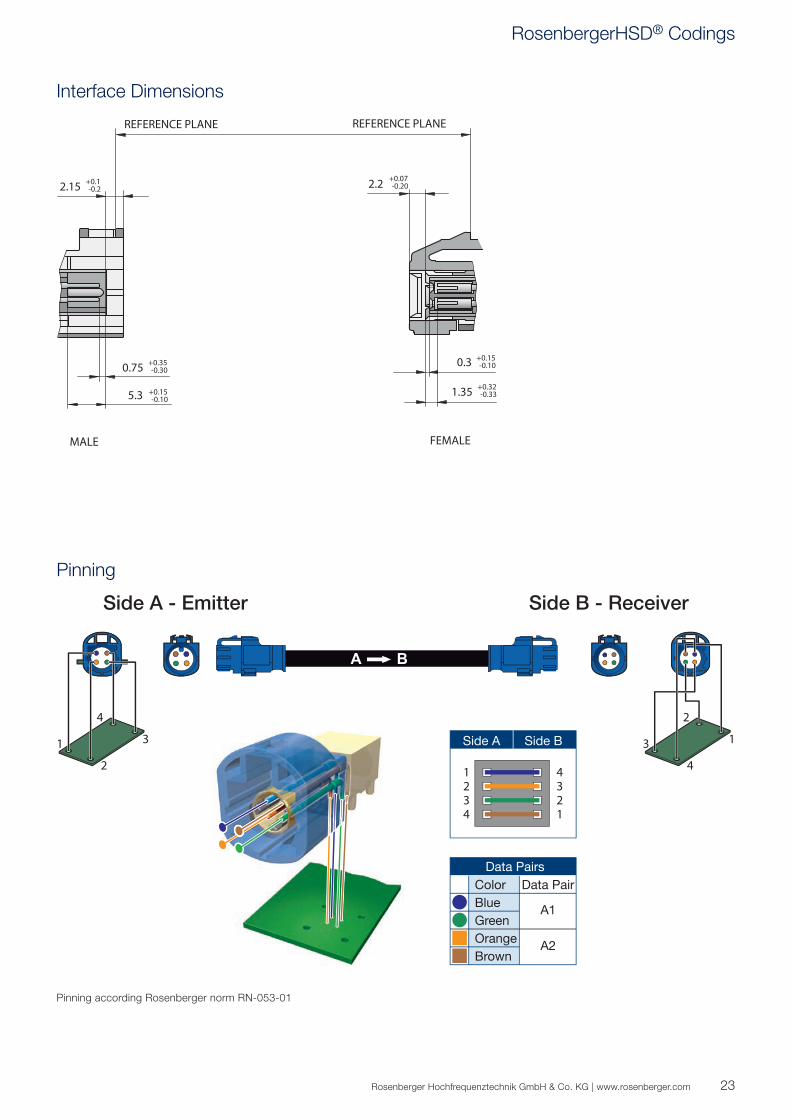
Side A - Emitter
left down right left down right
Side B - Receiver
Cable Exit
PCB connector (plug)
Side A – Emitter Side B – Receiver
18
Coding RosenbergerHSD®, HSD®e, HSD®+2, HSD®+4, Cable down, left, right
RosenbergerHSD® Codings
Definition Cable Exit down, left, right
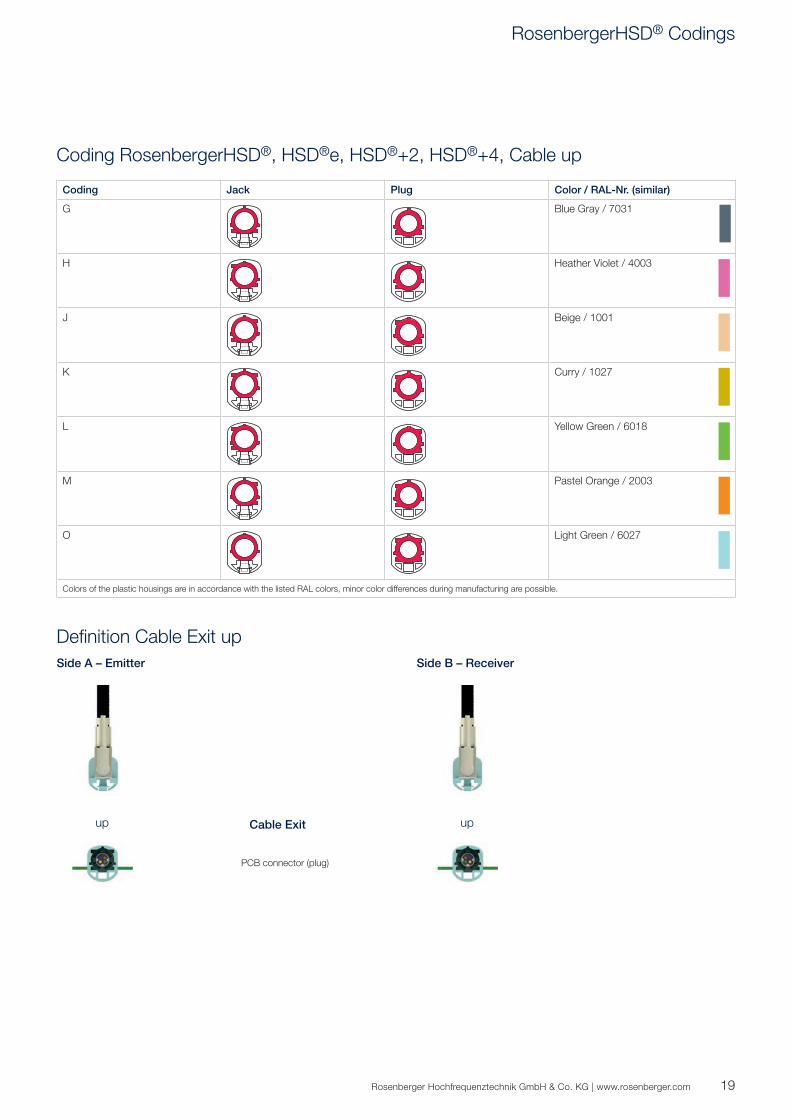
Coding Jack Plug Color / RAL-Nr. (similar)
G Blue Gray / 7031
H Heather Violet / 4003
J Beige / 1001
K Curry / 1027
L Yellow Green / 6018
M Pastel Orange / 2003
O Light Green / 6027
Colors of the plastic housings are in accordance with the listed RAL colors, minor color differences during manufacturing are possible.
19Rosenberger Hochfrequenztechnik GmbH & Co. KG | www.rosenberger.com
Coding RosenbergerHSD®, HSD®e, HSD®+2, HSD®+4, Cable up
Definition Cable Exit upSide A – Emitter Side B – Receiver
Cable Exitup up
RosenbergerHSD® Codings
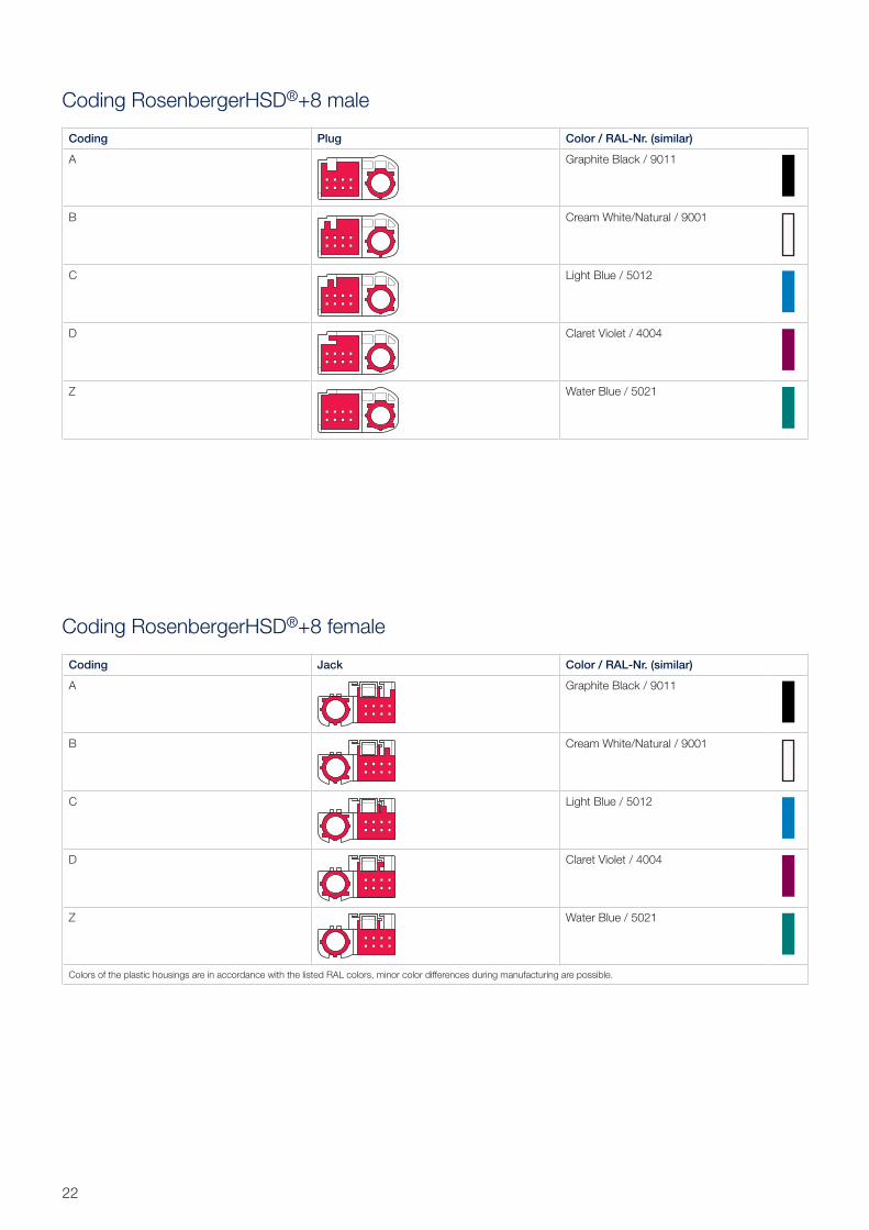
Coding Plug Color / RAL-Nr. (similar)
A Jet Black / 9005
B Cream White / 9001
C Signal Blue / 5005
D Claret Violet / 4004
E Leaf Green / 6002
F Nut Brown / 8011
Z Water Blue / 5021
Coding Jack Color / RAL-Nr. (similar)
A Jet Black / 9005
B Cream White / 9001
C Signal Blue / 5005
D Claret Violet / 4004
E Leaf Green / 6002
F Nut Brown / 8011
Z Water Blue / 5021
Colors of the plastic housings are in accordance with the listed RAL colors, minor color differences during manufacturing are possible.
20
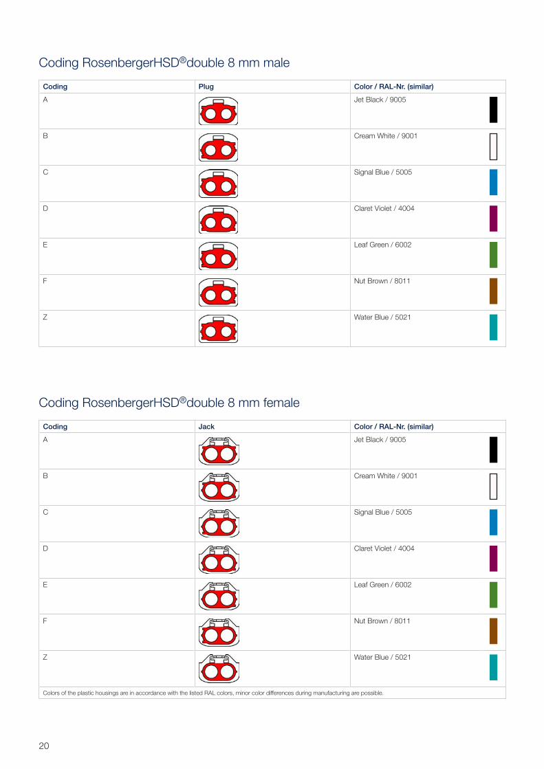
Coding RosenbergerHSD®double 8 mm male
Coding RosenbergerHSD®double 8 mm female
Coding Plug Color / RAL-Nr. (similar)
A (A+B) Graphite Black / 9011
B (B+A) Cream White / 9001
C (C+D) Light Blue / 5012
D (D+C) Claret Violet / 4004
E (E+F) May Green / 6017
F (F+E) Nut Brown / 8011
Z (Z+Z) Water Blue / 5021
Coding Jack Color / RAL-Nr. (similar)
A (A+B) Graphite Black / 9011
B (B+A) Cream White / 9001
C (C+D) Light Blue/ 5012
D (D+C) Claret Violet / 4004
E (E+F) May Green / 6017
F (F+E) Nut Brown / 8011
Z (Z+Z) Water Blue / 5021
Colors of the plastic housings are in accordance with the listed RAL colors, minor color differences during manufacturing are possible.
21Rosenberger Hochfrequenztechnik GmbH & Co. KG | www.rosenberger.com
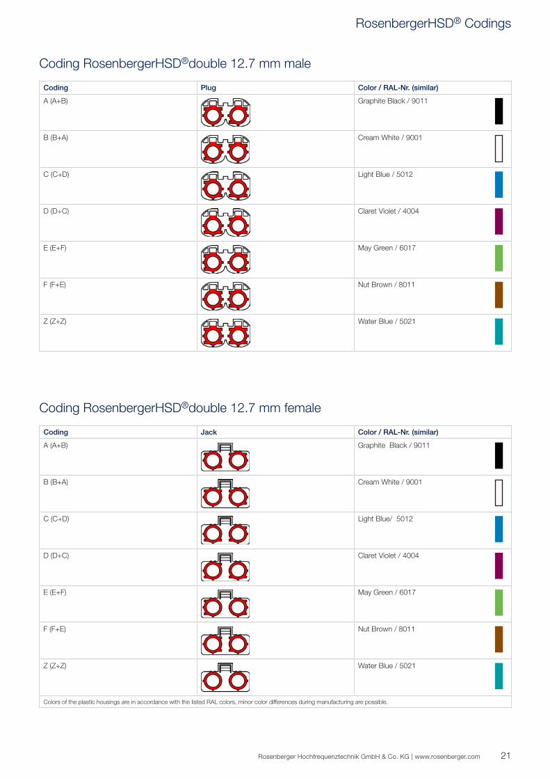
Coding RosenbergerHSD®double 12.7 mm male
Coding RosenbergerHSD®double 12.7 mm female
RosenbergerHSD® Codings
Coding Plug Color / RAL-Nr. (similar)
A Graphite Black / 9011
B Cream White/Natural / 9001
C Light Blue / 5012
D Claret Violet / 4004
Z Water Blue / 5021
Coding Jack Color / RAL-Nr. (similar)
A Graphite Black / 9011
B Cream White/Natural / 9001
C Light Blue / 5012
D Claret Violet / 4004
Z Water Blue / 5021
Colors of the plastic housings are in accordance with the listed RAL colors, minor color differences during manufacturing are possible.
22
Coding RosenbergerHSD®+8 male
Coding RosenbergerHSD®+8 female
1234 1
234
1
2
3
4
3
4
1
2
REFERENCE PLANE
MALE FEMALE
2.15 +0.1-0.2 2.2 +0.07
-0.20
0.3 +0.15-0.10
1.35 +0.32-0.33
0.75 +0.35-0.30
5.3 +0.15-0.10
REFERENCE PLANE
23Rosenberger Hochfrequenztechnik GmbH & Co. KG | www.rosenberger.com
Interface Dimensions
Pinning
Pinning according Rosenberger norm RN-053-01
RosenbergerHSD® Codings
24
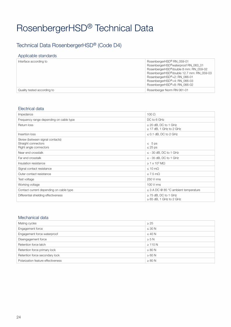
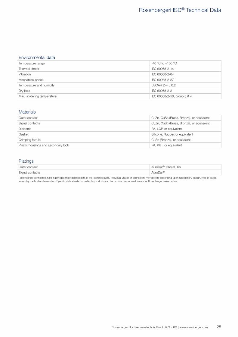
Technical Data RosenbergerHSD® (Code D4)
RosenbergerHSD® Technical Data
Applicable standardsInterface according to RosenbergerHSD® RN_059-01
RosenbergerHSD®waterproof RN_063_01RosenbergerHSD®double 8 mm: RN_059-02RosenbergerHSD®double 12.7 mm: RN_059-03RosenbergerHSD®+2: RN_066-01RosenbergerHSD®+4: RN_066-03RosenbergerHSD®+8: RN_066-02
Quality tested according to Rosenberger Norm RN 061-01
Electrical dataImpedance 100 Ω
Frequency range depending on cable type DC to 6 GHz
Return loss ≥ 20 dB, DC to 1 GHz≥ 17 dB, 1 GHz to 2 GHz
Insertion loss ≤ 0.1 dB, DC to 2 GHz
Skrew (between signal contacts)Straight connectorsRight angle connectors
≤ 5 ps≤ 25 ps
Near end crosstalk ≤ - 30 dB, DC to 1 GHz
Far end crosstalk ≤ - 35 dB, DC to 1 GHz
Insulation resistance ≥ 1 x 10³ MΩ
Signal contact resistance ≤ 10 mΩ
Outer contact resistance ≤ 7.5 mΩ
Test voltage 250 V rms
Working voltage 100 V rms
Contact current depending on cable type ≤ 3 A DC @ 85 °C ambient temperature
Differential shielding effectiveness ≥ 75 dB, DC to 1 GHz≥ 65 dB, 1 GHz to 2 GHz
Mechanical dataMating cycles ≥ 25
Engagement force ≤ 30 N
Engagement force waterproof ≤ 40 N
Disengagement force ≥ 5 N
Retention force latch ≥ 110 N
Retention force primary lock ≥ 80 N
Retention force secondary lock ≥ 60 N
Polarization feature effectiveness ≥ 80 N
25Rosenberger Hochfrequenztechnik GmbH & Co. KG | www.rosenberger.com
MaterialsOuter contact CuZn, CuSn (Brass, Bronze), or equivalent
Signal contacts CuZn, CuSn (Brass, Bronze), or equivalent
Dielectric PA, LCP, or equivalent
Gasket Silicone, Rubber, or equivalent
Crimping ferrule CuSn (Bronze), or equivalent
Plastic housings and secondary lock PA, PBT, or equivalent
PlatingsOuter contact AuroDur®, Nickel, Tin
Signal contacts AuroDur®
Rosenberger connectors fulfill in principle the indicated data of the Technical Data. Individual values of connectors may deviate depending upon application, design, type of cable, assembly method and execution. Specific data sheets for particular products can be provided on request from your Rosenberger sales partner.
Environmental dataTemperature range -40 °C to +105 °C
Thermal shock IEC 60068-2-14
Vibration IEC 60068-2-64
Mechanical shock IEC 60068-2-27
Temperature and humidity USCAR 2-4 5.6.2
Dry heat IEC 60068-2-2
Max. soldering temperature IEC 60068-2-58, group 3 & 4
RosenbergerHSD® Technical Data
26
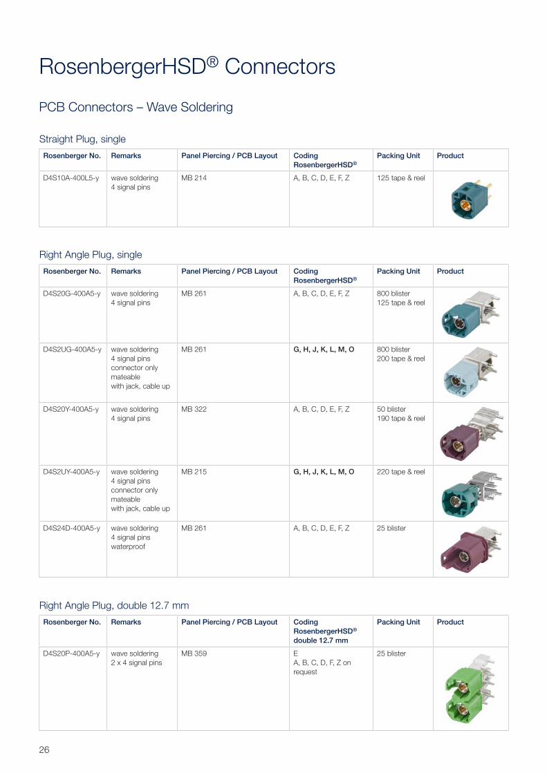
PCB Connectors – Wave Soldering
RosenbergerHSD® Connectors
Straight Plug, single
Rosenberger No. Remarks Panel Piercing / PCB Layout Coding RosenbergerHSD®
Packing Unit Product
D4S10A-400L5-y wave soldering4 signal pins
MB 214 A, B, C, D, E, F, Z 125 tape & reel
Right Angle Plug, single
Rosenberger No. Remarks Panel Piercing / PCB Layout Coding RosenbergerHSD®
Packing Unit Product
D4S20G-400A5-y wave soldering4 signal pins
MB 261 A, B, C, D, E, F, Z 800 blister125 tape & reel
D4S2UG-400A5-y wave soldering4 signal pinsconnector only mateablewith jack, cable up
MB 261 G, H, J, K, L, M, O 800 blister200 tape & reel
D4S20Y-400A5-y wave soldering4 signal pins
MB 322 A, B, C, D, E, F, Z 50 blister190 tape & reel
D4S2UY-400A5-y wave soldering4 signal pinsconnector only mateablewith jack, cable up
MB 215 G, H, J, K, L, M, O 220 tape & reel
D4S24D-400A5-y wave soldering4 signal pinswaterproof
MB 261 A, B, C, D, E, F, Z 25 blister
Right Angle Plug, double 12.7 mm
Rosenberger No. Remarks Panel Piercing / PCB Layout Coding RosenbergerHSD® double 12.7 mm
Packing Unit Product
D4S20P-400A5-y wave soldering2 x 4 signal pins
MB 359 EA, B, C, D, F, Z on request
25 blister
27Rosenberger Hochfrequenztechnik GmbH & Co. KG | www.rosenberger.com
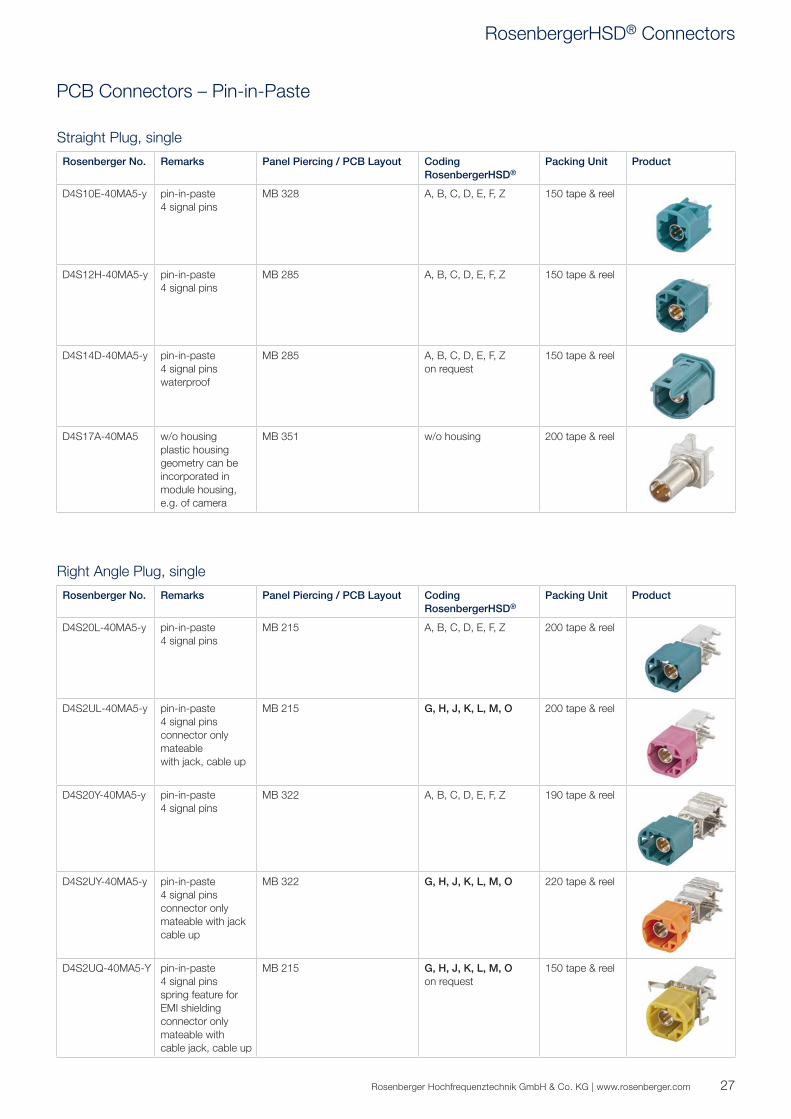
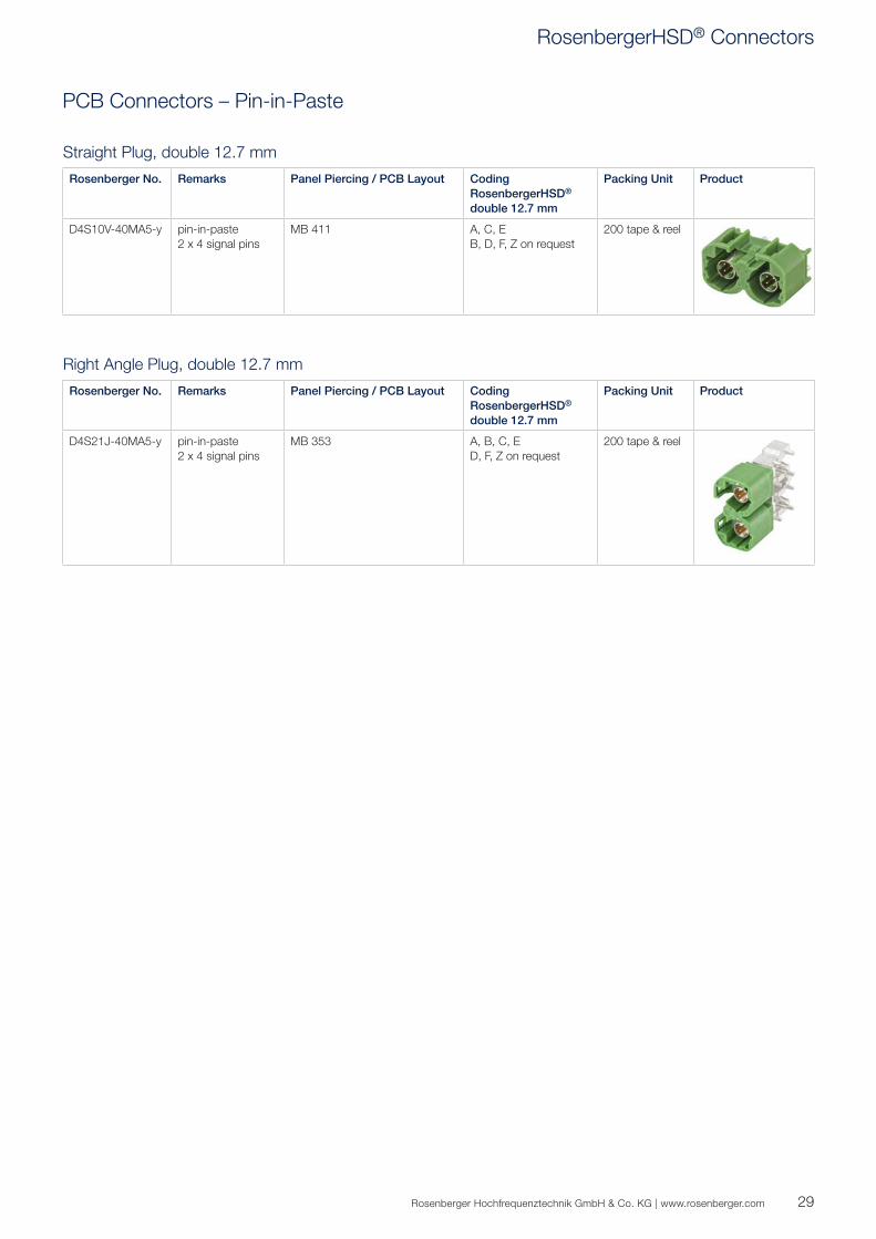
PCB Connectors – Pin-in-Paste
Straight Plug, single
Rosenberger No. Remarks Panel Piercing / PCB Layout Coding RosenbergerHSD®
Packing Unit Product
D4S10E-40MA5-y pin-in-paste4 signal pins
MB 328 A, B, C, D, E, F, Z 150 tape & reel
D4S12H-40MA5-y pin-in-paste4 signal pins
MB 285 A, B, C, D, E, F, Z 150 tape & reel
D4S14D-40MA5-y pin-in-paste4 signal pinswaterproof
MB 285 A, B, C, D, E, F, Zon request
150 tape & reel
D4S17A-40MA5 w/o housingplastic housing geometry can be incorporated in module housing, e.g. of camera
MB 351 w/o housing 200 tape & reel
Right Angle Plug, single
Rosenberger No. Remarks Panel Piercing / PCB Layout Coding RosenbergerHSD®
Packing Unit Product
D4S20L-40MA5-y pin-in-paste4 signal pins
MB 215 A, B, C, D, E, F, Z 200 tape & reel
D4S2UL-40MA5-y pin-in-paste4 signal pinsconnector only mateablewith jack, cable up
MB 215 G, H, J, K, L, M, O 200 tape & reel
D4S20Y-40MA5-y pin-in-paste4 signal pins
MB 322 A, B, C, D, E, F, Z 190 tape & reel
D4S2UY-40MA5-y pin-in-paste4 signal pinsconnector only mateable with jack cable up
MB 322 G, H, J, K, L, M, O 220 tape & reel
D4S2UQ-40MA5-Y pin-in-paste4 signal pinsspring feature for EMI shielding connector only mateable with cable jack, cable up
MB 215 G, H, J, K, L, M, Oon request
150 tape & reel
RosenbergerHSD® Connectors
28
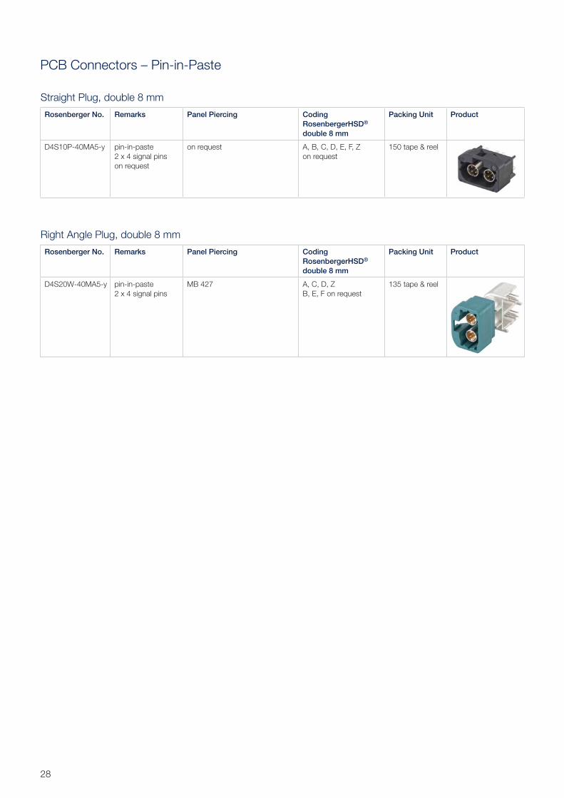
PCB Connectors – Pin-in-Paste
Straight Plug, double 8 mm
Rosenberger No. Remarks Panel Piercing Coding RosenbergerHSD® double 8 mm
Packing Unit Product
D4S10P-40MA5-y pin-in-paste2 x 4 signal pinson request
on request A, B, C, D, E, F, Z on request
150 tape & reel
Right Angle Plug, double 8 mm
Rosenberger No. Remarks Panel Piercing Coding RosenbergerHSD® double 8 mm
Packing Unit Product
D4S20W-40MA5-y pin-in-paste2 x 4 signal pins
MB 427 A, C, D, ZB, E, F on request
135 tape & reel
29Rosenberger Hochfrequenztechnik GmbH & Co. KG | www.rosenberger.com
PCB Connectors – Pin-in-Paste
Straight Plug, double 12.7 mm
Rosenberger No. Remarks Panel Piercing / PCB Layout Coding RosenbergerHSD® double 12.7 mm
Packing Unit Product
D4S10V-40MA5-y pin-in-paste2 x 4 signal pins
MB 411 A, C, EB, D, F, Z on request
200 tape & reel
Right Angle Plug, double 12.7 mm
Rosenberger No. Remarks Panel Piercing / PCB Layout Coding RosenbergerHSD® double 12.7 mm
Packing Unit Product
D4S21J-40MA5-y pin-in-paste2 x 4 signal pins
MB 353 A, B, C, ED, F, Z on request
200 tape & reel
RosenbergerHSD® Connectors
30
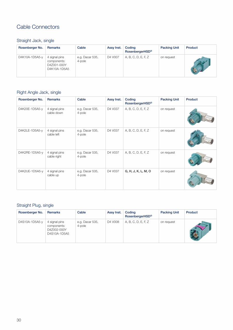
Cable Connectors
Straight Plug, single
Rosenberger No. Remarks Cable Assy Inst. Coding RosenbergerHSD®
Packing Unit Product
D4S10A-1D5A5-y 4 signal pinscomponents:D4Z002-000YD4S10A-1D5A5
e.g. Dacar 535, 4-pole
D4 V008 A, B, C, D, E, F, Z on request
Straight Jack, single
Rosenberger No. Remarks Cable Assy Inst. Coding RosenbergerHSD®
Packing Unit Product
D4K10A-1D5A5-y 4 signal pinscomponents:D4Z001-000YD4K10A-1D5A5
e.g. Dacar 535, 4-pole
D4 V007 A, B, C, D, E, F, Z on request
Right Angle Jack, single
Rosenberger No. Remarks Cable Assy Inst. Coding RosenbergerHSD®
Packing Unit Product
D4K20E-1D5A5-y 4 signal pinscable down
e.g. Dacar 535, 4-pole
D4 V037 A, B, C, D, E, F, Z on request
D4K2LE-1D5A5-y 4 signal pinscable left
e.g. Dacar 535, 4-pole
D4 V037 A, B, C, D, E, F, Z on request
D4K2RE-1D5A5-y 4 signal pinscable right
e.g. Dacar 535, 4-pole
D4 V037 A, B, C, D, E, F, Z on request
D4K2UE-1D5A5-y 4 signal pinscable up
e.g. Dacar 535, 4-pole
D4 V037 G, H, J, K, L, M, O on request
31Rosenberger Hochfrequenztechnik GmbH & Co. KG | www.rosenberger.com
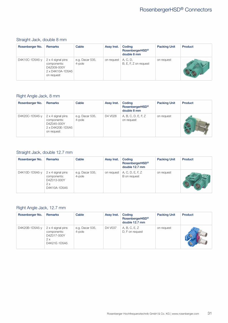
Straight Jack, double 8 mm
Rosenberger No. Remarks Cable Assy Inst. Coding RosenbergerHSD® double 8 mm
Packing Unit Product
D4K10C-1D5A5-y 2 x 4 signal pinscomponents:D4Z009-000Y2 x D4K10A-1D5A5on request
e.g. Dacar 535, 4-pole
on request A, C, D,B, E, F, Z on request
on request
Right Angle Jack, 8 mm
Rosenberger No. Remarks Cable Assy Inst. Coding RosenbergerHSD® double 8 mm
Packing Unit Product
D4K20C-1D5A5-y 2 x 4 signal pinscomponents:D4Z045-000Y2 x D4K20E-1D5A5on request
e.g. Dacar 535, 4-pole
D4 V028 A, B, C, D, E, F, Z on request
on request
Straight Jack, double 12.7 mm
Rosenberger No. Remarks Cable Assy Inst. Coding RosenbergerHSD® double 12.7 mm
Packing Unit Product
D4K10D-1D5A5-y 2 x 4 signal pinscomponents:D4Z013-000Y2 x D4K10A-1D5A5
e.g. Dacar 535, 4-pole
on request A, C, D, E, F, ZB on request
on request
Right Angle Jack, 12.7 mm
Rosenberger No. Remarks Cable Assy Inst. Coding RosenbergerHSD® double 12.7 mm
Packing Unit Product
D4K20B-1D5A5-y 2 x 4 signal pinscomponents:D4Z017-000Y2 x D4K21E-1D5A5
e.g. Dacar 535, 4-pole
D4 V037 A, B, C, E, Z D, F on request
on request
RosenbergerHSD® Connectors
32
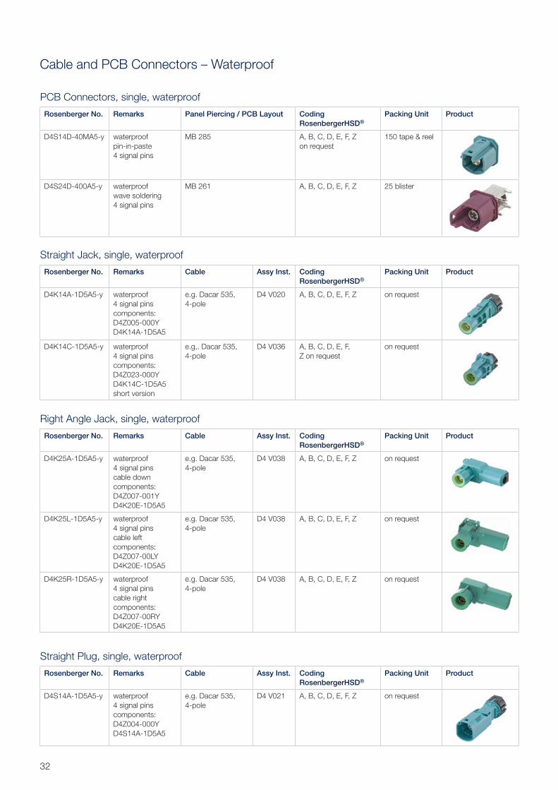
Cable and PCB Connectors – Waterproof
Straight Plug, single, waterproof
Rosenberger No. Remarks Cable Assy Inst. Coding RosenbergerHSD®
Packing Unit Product
D4S14A-1D5A5-y waterproof4 signal pinscomponents:D4Z004-000YD4S14A-1D5A5
e.g. Dacar 535, 4-pole
D4 V021 A, B, C, D, E, F, Z on request
Straight Jack, single, waterproof
Rosenberger No. Remarks Cable Assy Inst. Coding RosenbergerHSD®
Packing Unit Product
D4K14A-1D5A5-y waterproof4 signal pinscomponents:D4Z005-000YD4K14A-1D5A5
e.g. Dacar 535, 4-pole
D4 V020 A, B, C, D, E, F, Z on request
D4K14C-1D5A5-y waterproof4 signal pinscomponents:D4Z023-000YD4K14C-1D5A5 short version
e.g,. Dacar 535, 4-pole
D4 V036 A, B, C, D, E, F, Z on request
on request
Right Angle Jack, single, waterproof
Rosenberger No. Remarks Cable Assy Inst. Coding RosenbergerHSD®
Packing Unit Product
D4K25A-1D5A5-y waterproof4 signal pinscable downcomponents:D4Z007-001YD4K20E-1D5A5
e.g. Dacar 535, 4-pole
D4 V038 A, B, C, D, E, F, Z on request
D4K25L-1D5A5-y waterproof4 signal pinscable leftcomponents:D4Z007-00LYD4K20E-1D5A5
e.g. Dacar 535, 4-pole
D4 V038 A, B, C, D, E, F, Z on request
D4K25R-1D5A5-y waterproof4 signal pinscable rightcomponents:D4Z007-00RYD4K20E-1D5A5
e.g. Dacar 535, 4-pole
D4 V038 A, B, C, D, E, F, Z on request
PCB Connectors, single, waterproof
Rosenberger No. Remarks Panel Piercing / PCB Layout Coding RosenbergerHSD®
Packing Unit Product
D4S14D-40MA5-y waterproofpin-in-paste4 signal pins
MB 285 A, B, C, D, E, F, Zon request
150 tape & reel
D4S24D-400A5-y waterproofwave soldering4 signal pins
MB 261 A, B, C, D, E, F, Z 25 blister
33Rosenberger Hochfrequenztechnik GmbH & Co. KG | www.rosenberger.com
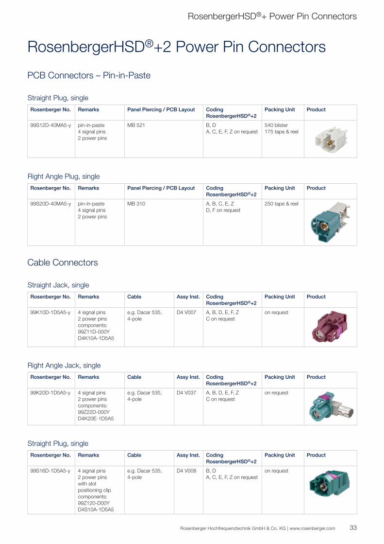
Cable Connectors
Straight Plug, single
Rosenberger No. Remarks Cable Assy Inst. Coding RosenbergerHSD®+2
Packing Unit Product
99S16D-1D5A5-y 4 signal pins2 power pinswith slot positioning clipcomponents:99Z120-D00YD4S10A-1D5A5
e.g. Dacar 535, 4-pole
D4 V008 B, DA, C, E, F, Z on request
on request
Straight Jack, single
Rosenberger No. Remarks Cable Assy Inst. Coding RosenbergerHSD®+2
Packing Unit Product
99K10D-1D5A5-y 4 signal pins2 power pinscomponents:99Z11D-000YD4K10A-1D5A5
e.g. Dacar 535, 4-pole
D4 V007 A, B, D, E, F, ZC on request
on request
Right Angle Jack, single
Rosenberger No. Remarks Cable Assy Inst. Coding RosenbergerHSD®+2
Packing Unit Product
99K20D-1D5A5-y 4 signal pins2 power pinscomponents:99Z22D-000YD4K20E-1D5A5
e.g. Dacar 535, 4-pole
D4 V037 A, B, D, E, F, ZC on request
on request
PCB Connectors – Pin-in-Paste
Straight Plug, single
Rosenberger No. Remarks Panel Piercing / PCB Layout Coding RosenbergerHSD®+2
Packing Unit Product
99S12D-40MA5-y pin-in-paste4 signal pins2 power pins
MB 521 B, D A, C, E, F, Z on request
540 blister175 tape & reel
Right Angle Plug, single
Rosenberger No. Remarks Panel Piercing / PCB Layout Coding RosenbergerHSD®+2
Packing Unit Product
99S20D-40MA5-y pin-in-paste4 signal pins2 power pins
MB 310 A, B, C, E, ZD, F on request
250 tape & reel
RosenbergerHSD®+ Power Pin Connectors
RosenbergerHSD®+2 Power Pin Connectors
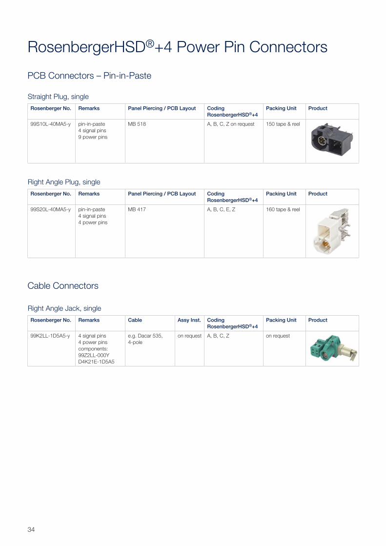
34
Cable Connectors
Right Angle Jack, single
Rosenberger No. Remarks Cable Assy Inst. Coding RosenbergerHSD®+4
Packing Unit Product
99K2LL-1D5A5-y 4 signal pins4 power pinscomponents:99Z2LL-000YD4K21E-1D5A5
e.g. Dacar 535, 4-pole
on request A, B, C, Z on request
PCB Connectors – Pin-in-Paste
Straight Plug, single
Rosenberger No. Remarks Panel Piercing / PCB Layout Coding RosenbergerHSD®+4
Packing Unit Product
99S10L-40MA5-y pin-in-paste4 signal pins9 power pins
MB 518 A, B, C, Z on request 150 tape & reel
Right Angle Plug, single
Rosenberger No. Remarks Panel Piercing / PCB Layout Coding RosenbergerHSD®+4
Packing Unit Product
99S20L-40MA5-y pin-in-paste4 signal pins4 power pins
MB 417 A, B, C, E, Z 160 tape & reel
RosenbergerHSD®+4 Power Pin Connectors
35Rosenberger Hochfrequenztechnik GmbH & Co. KG | www.rosenberger.com
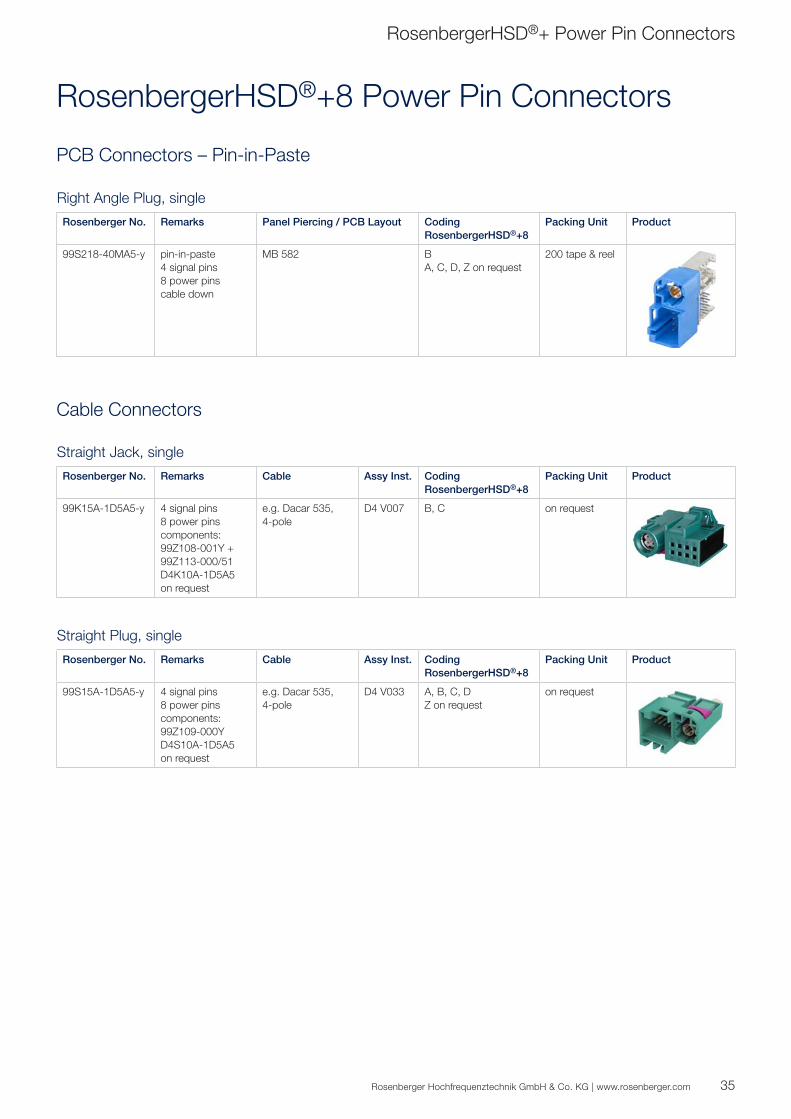
Cable Connectors
Straight Plug, single
Rosenberger No. Remarks Cable Assy Inst. Coding RosenbergerHSD®+8
Packing Unit Product
99S15A-1D5A5-y 4 signal pins8 power pinscomponents:99Z109-000YD4S10A-1D5A5on request
e.g. Dacar 535, 4-pole
D4 V033 A, B, C, DZ on request
on request
Straight Jack, single
Rosenberger No. Remarks Cable Assy Inst. Coding RosenbergerHSD®+8
Packing Unit Product
99K15A-1D5A5-y 4 signal pins8 power pinscomponents:99Z108-001Y + 99Z113-000/51D4K10A-1D5A5on request
e.g. Dacar 535, 4-pole
D4 V007 B, C on request
PCB Connectors – Pin-in-Paste
Right Angle Plug, single
Rosenberger No. Remarks Panel Piercing / PCB Layout Coding RosenbergerHSD®+8
Packing Unit Product
99S218-40MA5-y pin-in-paste4 signal pins8 power pinscable down
MB 582 BA, C, D, Z on request
200 tape & reel
RosenbergerHSD®+ Power Pin Connectors
RosenbergerHSD®+8 Power Pin Connectors
36
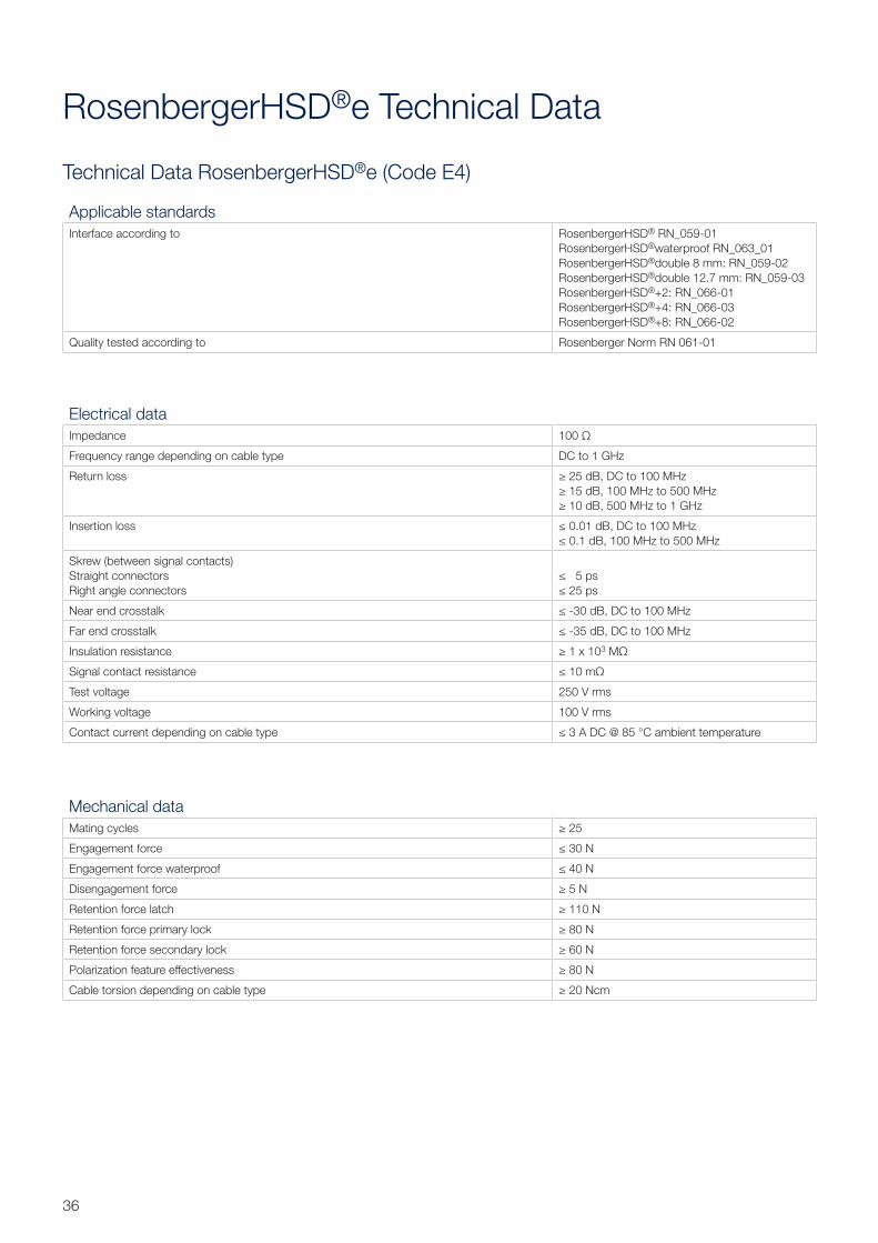
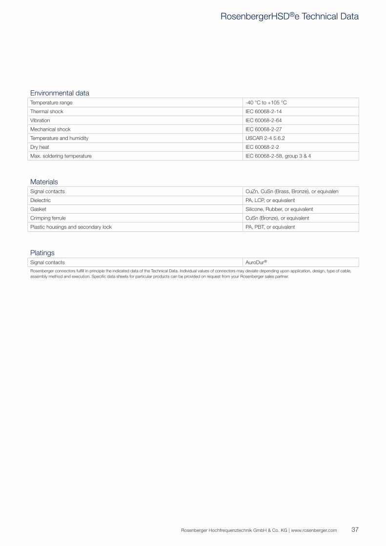
Technical Data RosenbergerHSD®e (Code E4)
RosenbergerHSD®e Technical Data
Applicable standardsInterface according to RosenbergerHSD® RN_059-01
RosenbergerHSD®waterproof RN_063_01RosenbergerHSD®double 8 mm: RN_059-02RosenbergerHSD®double 12.7 mm: RN_059-03RosenbergerHSD®+2: RN_066-01RosenbergerHSD®+4: RN_066-03RosenbergerHSD®+8: RN_066-02
Quality tested according to Rosenberger Norm RN 061-01
Electrical dataImpedance 100 Ω
Frequency range depending on cable type DC to 1 GHz
Return loss ≥ 25 dB, DC to 100 MHz≥ 15 dB, 100 MHz to 500 MHz≥ 10 dB, 500 MHz to 1 GHz
Insertion loss ≤ 0.01 dB, DC to 100 MHz≤ 0.1 dB, 100 MHz to 500 MHz
Skrew (between signal contacts)Straight connectorsRight angle connectors
≤ 5 ps≤ 25 ps
Near end crosstalk ≤ -30 dB, DC to 100 MHz
Far end crosstalk ≤ -35 dB, DC to 100 MHz
Insulation resistance ≥ 1 x 10³ MΩ
Signal contact resistance ≤ 10 mΩ
Test voltage 250 V rms
Working voltage 100 V rms
Contact current depending on cable type ≤ 3 A DC @ 85 °C ambient temperature
Mechanical dataMating cycles ≥ 25
Engagement force ≤ 30 N
Engagement force waterproof ≤ 40 N
Disengagement force ≥ 5 N
Retention force latch ≥ 110 N
Retention force primary lock ≥ 80 N
Retention force secondary lock ≥ 60 N
Polarization feature effectiveness ≥ 80 N
Cable torsion depending on cable type ≥ 20 Ncm
37Rosenberger Hochfrequenztechnik GmbH & Co. KG | www.rosenberger.com
MaterialsSignal contacts CuZn, CuSn (Brass, Bronze), or equivalen
Dielectric PA, LCP, or equivalent
Gasket Silicone, Rubber, or equivalent
Crimping ferrule CuSn (Bronze), or equivalent
Plastic housings and secondary lock PA, PBT, or equivalent
PlatingsSignal contacts AuroDur®
Rosenberger connectors fulfill in principle the indicated data of the Technical Data. Individual values of connectors may deviate depending upon application, design, type of cable, assembly method and execution. Specific data sheets for particular products can be provided on request from your Rosenberger sales partner.
Environmental dataTemperature range -40 °C to +105 °C
Thermal shock IEC 60068-2-14
Vibration IEC 60068-2-64
Mechanical shock IEC 60068-2-27
Temperature and humidity USCAR 2-4 5.6.2
Dry heat IEC 60068-2-2
Max. soldering temperature IEC 60068-2-58, group 3 & 4
RosenbergerHSD®e Technical Data
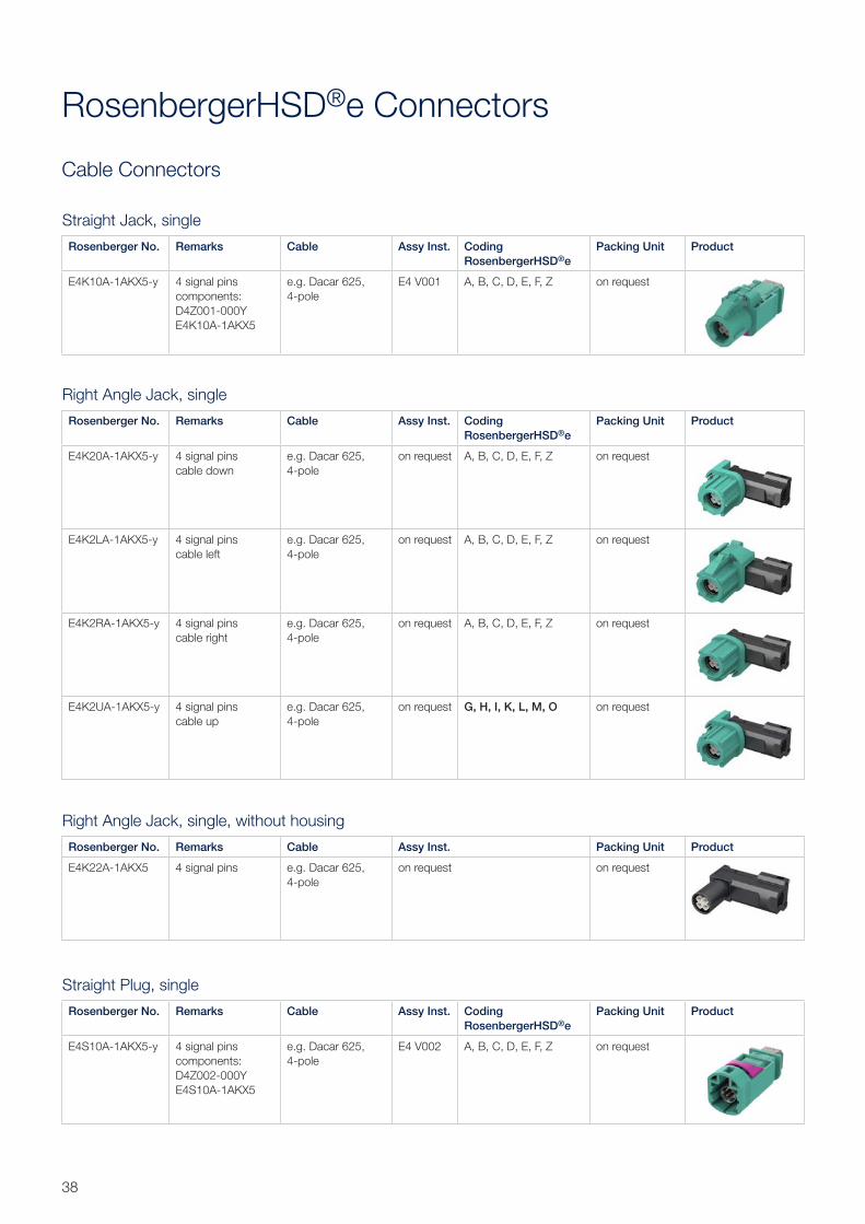
38
Cable Connectors
RosenbergerHSD®e Connectors
Straight Plug, single
Rosenberger No. Remarks Cable Assy Inst. Coding RosenbergerHSD®e
Packing Unit Product
E4S10A-1AKX5-y 4 signal pinscomponents:D4Z002-000YE4S10A-1AKX5
e.g. Dacar 625, 4-pole
E4 V002 A, B, C, D, E, F, Z on request
Straight Jack, single
Rosenberger No. Remarks Cable Assy Inst. Coding RosenbergerHSD®e
Packing Unit Product
E4K10A-1AKX5-y 4 signal pinscomponents:D4Z001-000YE4K10A-1AKX5
e.g. Dacar 625, 4-pole
E4 V001 A, B, C, D, E, F, Z on request
Right Angle Jack, single
Rosenberger No. Remarks Cable Assy Inst. Coding RosenbergerHSD®e
Packing Unit Product
E4K20A-1AKX5-y 4 signal pinscable down
e.g. Dacar 625, 4-pole
on request A, B, C, D, E, F, Z on request
E4K2LA-1AKX5-y 4 signal pinscable left
e.g. Dacar 625, 4-pole
on request A, B, C, D, E, F, Z on request
E4K2RA-1AKX5-y 4 signal pinscable right
e.g. Dacar 625, 4-pole
on request A, B, C, D, E, F, Z on request
E4K2UA-1AKX5-y 4 signal pinscable up
e.g. Dacar 625, 4-pole
on request G, H, I, K, L, M, O on request
Right Angle Jack, single, without housing
Rosenberger No. Remarks Cable Assy Inst. Packing Unit Product
E4K22A-1AKX5 4 signal pins e.g. Dacar 625, 4-pole
on request on request
39Rosenberger Hochfrequenztechnik GmbH & Co. KG | www.rosenberger.com
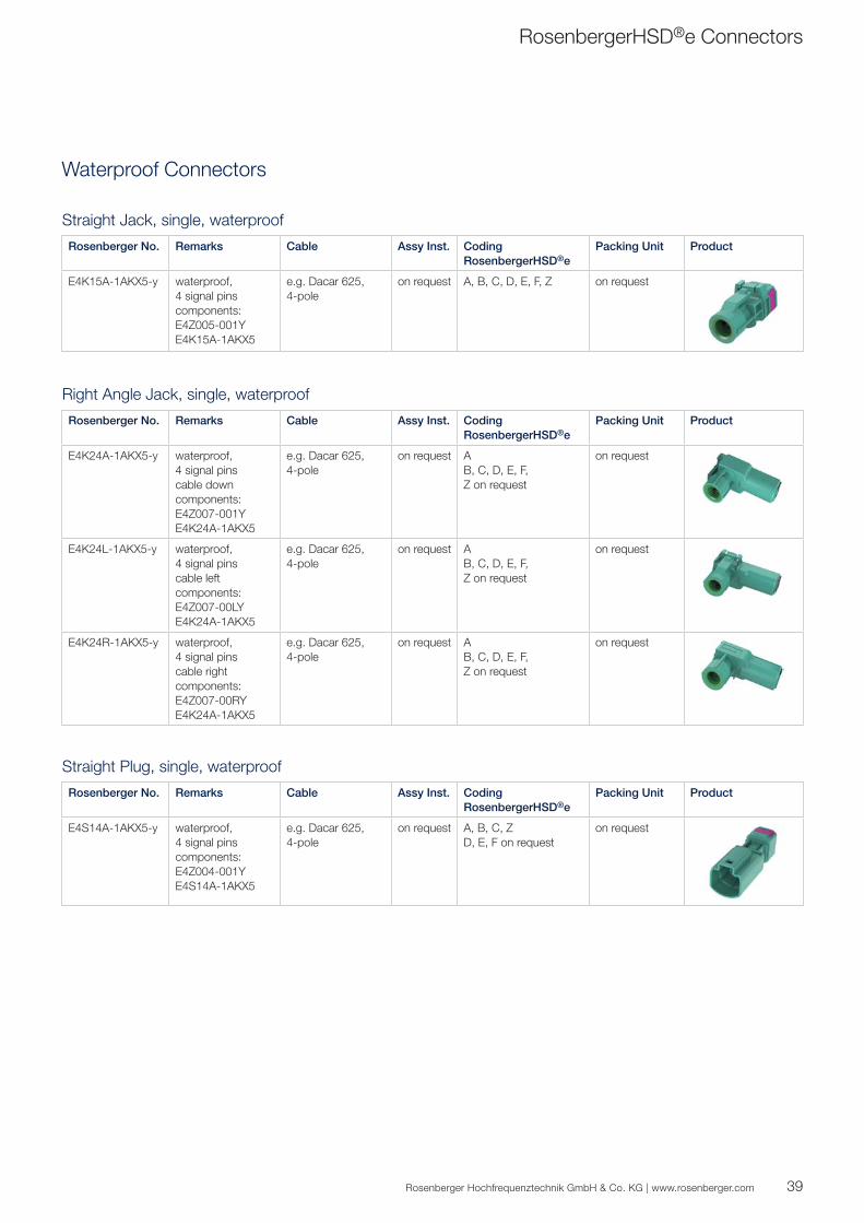
Waterproof Connectors
Straight Plug, single, waterproof
Rosenberger No. Remarks Cable Assy Inst. Coding RosenbergerHSD®e
Packing Unit Product
E4S14A-1AKX5-y waterproof,4 signal pinscomponents:E4Z004-001YE4S14A-1AKX5
e.g. Dacar 625, 4-pole
on request A, B, C, ZD, E, F on request
on request
Straight Jack, single, waterproof
Rosenberger No. Remarks Cable Assy Inst. Coding RosenbergerHSD®e
Packing Unit Product
E4K15A-1AKX5-y waterproof,4 signal pinscomponents:E4Z005-001YE4K15A-1AKX5
e.g. Dacar 625, 4-pole
on request A, B, C, D, E, F, Z on request
Right Angle Jack, single, waterproof
Rosenberger No. Remarks Cable Assy Inst. Coding RosenbergerHSD®e
Packing Unit Product
E4K24A-1AKX5-y waterproof,4 signal pinscable downcomponents:E4Z007-001YE4K24A-1AKX5
e.g. Dacar 625, 4-pole
on request AB, C, D, E, F, Z on request
on request
E4K24L-1AKX5-y waterproof,4 signal pinscable leftcomponents:E4Z007-00LYE4K24A-1AKX5
e.g. Dacar 625, 4-pole
on request AB, C, D, E, F, Z on request
on request
E4K24R-1AKX5-y waterproof,4 signal pinscable rightcomponents:E4Z007-00RYE4K24A-1AKX5
e.g. Dacar 625, 4-pole
on request AB, C, D, E, F, Z on request
on request
RosenbergerHSD®e Connectors
40
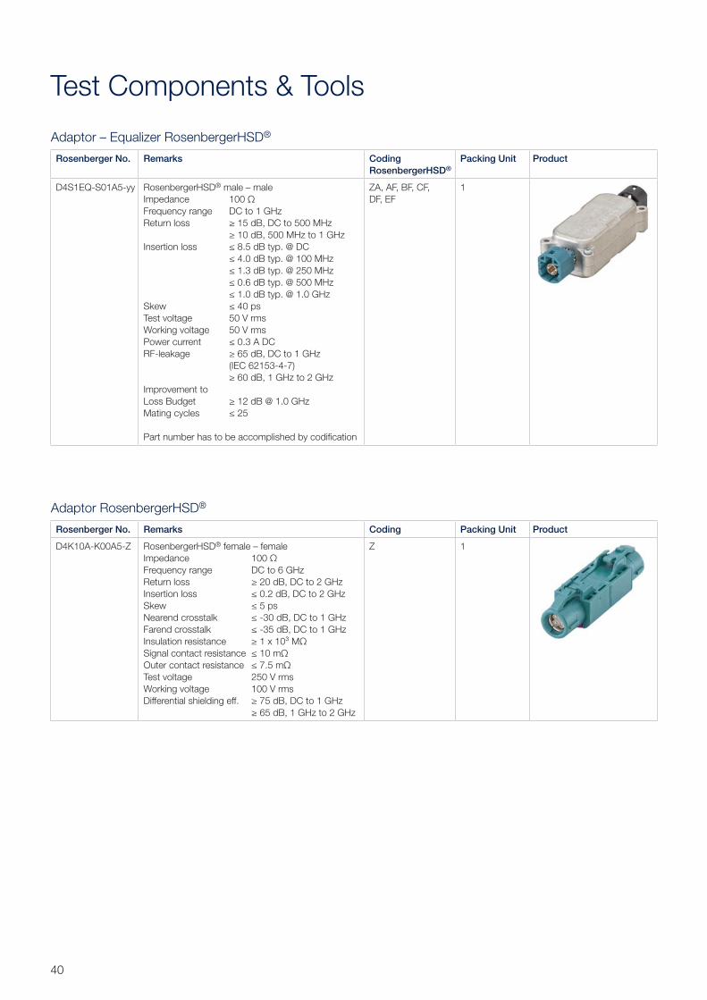
Adaptor RosenbergerHSD®
Rosenberger No. Remarks Coding Packing Unit Product
D4K10A-K00A5-Z RosenbergerHSD® female – femaleImpedance 100 ΩFrequency range DC to 6 GHzReturn loss ≥ 20 dB, DC to 2 GHzInsertion loss ≤ 0.2 dB, DC to 2 GHzSkew ≤ 5 psNearend crosstalk ≤ -30 dB, DC to 1 GHzFarend crosstalk ≤ -35 dB, DC to 1 GHzInsulation resistance ≥ 1 x 10³ MΩSignal contact resistance ≤ 10 mΩOuter contact resistance ≤ 7.5 mΩTest voltage 250 V rmsWorking voltage 100 V rmsDifferential shielding eff. ≥ 75 dB, DC to 1 GHz ≥ 65 dB, 1 GHz to 2 GHz
Z 1
Adaptor – Equalizer RosenbergerHSD®
Rosenberger No. Remarks Coding RosenbergerHSD®
Packing Unit Product
D4S1EQ-S01A5-yy RosenbergerHSD® male – maleImpedance 100 ΩFrequency range DC to 1 GHzReturn loss ≥ 15 dB, DC to 500 MHz ≥ 10 dB, 500 MHz to 1 GHzInsertion loss ≤ 8.5 dB typ. @ DC ≤ 4.0 dB typ. @ 100 MHz ≤ 1.3 dB typ. @ 250 MHz ≤ 0.6 dB typ. @ 500 MHz ≤ 1.0 dB typ. @ 1.0 GHzSkew ≤ 40 psTest voltage 50 V rmsWorking voltage 50 V rmsPower current ≤ 0.3 A DCRF-leakage ≥ 65 dB, DC to 1 GHz (IEC 62153-4-7) ≥ 60 dB, 1 GHz to 2 GHz Improvement to Loss Budget ≥ 12 dB @ 1.0 GHzMating cycles ≤ 25
Part number has to be accomplished by codification
ZA, AF, BF, CF, DF, EF
1
Test Components & Tools
41Rosenberger Hochfrequenztechnik GmbH & Co. KG | www.rosenberger.com
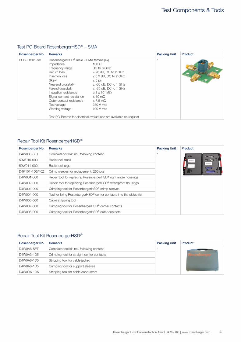
Test PC-Board RosenbergerHSD® – SMA
Rosenberger No. Remarks Packing Unit Product
PCB-L1501-SB RosenbergerHSD® male – SMA female (4x)Impedance 100 ΩFrequency range DC to 6 GHzReturn loss ≥ 20 dB, DC to 2 GHzInsertion loss ≤ 0.3 dB, DC to 2 GHzSkew ≤ 5 psNearend crosstalk ≤ -30 dB, DC to 1 GHzFarend crosstalk ≤ -35 dB, DC to 1 GHzInsulation resistance ≥ 1 x 10³ MΩSignal contact resistance ≤ 10 mΩOuter contact resistance ≤ 7.5 mΩTest voltage 250 V rmsWorking voltage 100 V rms
Test PC-Boards for electrical evaluations are available on request
1
Repair Tool Kit RosenbergerHSD®
Rosenberger No. Remarks Packing Unit Product
D4W006-SET Complete tool kit incl. following content 1
59W010-000 Basic tool small
59W011-000 Basic tool large
D4K101-1D5/40Z Crimp sleeves for replacement, 250 pcs
D4W001-000 Repair tool for replacing RosenbergerHSD® right angle housings
D4W002-000 Repair tool for replacing RosenbergerHSD® waterproof housings
D4W003-000 Crimping tool for RosenbergerHSD® crimp sleeves
D4W004-000 Tool for fixing RosenbergerHSD® center contacts into the dielectric
D4W006-000 Cable stripping tool
D4W007-000 Crimping tool for RosenbergerHSD® center contacts
D4W008-000 Crimping tool for RosenbergerHSD® outer contacts
Repair Tool Kit RosenbergerHSD®
Rosenberger No. Remarks Packing Unit Product
D4W0A6-SET Complete tool kit incl. following content 1
D4W0A3-1D5 Crimping tool for straight center contacts
D4W0A6-1D5 Stripping tool for cable jacket
D4W0A8-1D5 Crimping tool for support sleeves
D4W0B6-1D5 Stripping tool for cable conductors
Test Components & Tools
42
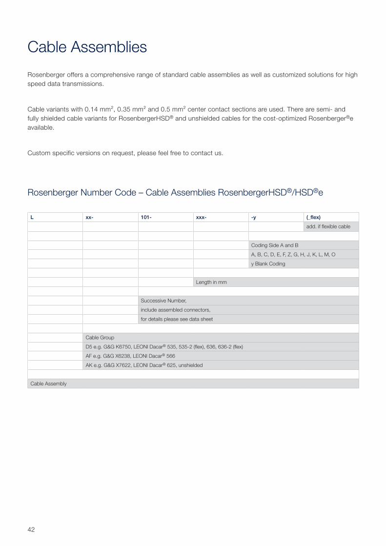
Cable Assemblies
Rosenberger offers a comprehensive range of standard cable assemblies as well as customized solutions for high speed data transmissions.
Cable variants with 0.14 mm², 0.35 mm² and 0.5 mm² center contact sections are used. There are semi- and fully shielded cable variants for RosenbergerHSD® and unshielded cables for the cost-optimized Rosenberger®e available.
Custom specific versions on request, please feel free to contact us.
L xx- 101- xxx- -y (_flex)
add. if flexible cable
Coding Side A and B
A, B, C, D, E, F, Z, G, H, J, K, L, M, O
y Blank Coding
Length in mm
Successive Number,
include assembled connectors,
for details please see data sheet
Cable Group
D5 e.g. G&G K6750, LEONI Dacar® 535, 535-2 (flex), 636, 636-2 (flex)
AF e.g. G&G X6238, LEONI Dacar® 566
AK e.g. G&G X7622, LEONI Dacar® 625, unshielded
Cable Assembly
Rosenberger Number Code – Cable Assemblies RosenbergerHSD®/HSD®e
43Rosenberger Hochfrequenztechnik GmbH & Co. KG | www.rosenberger.com
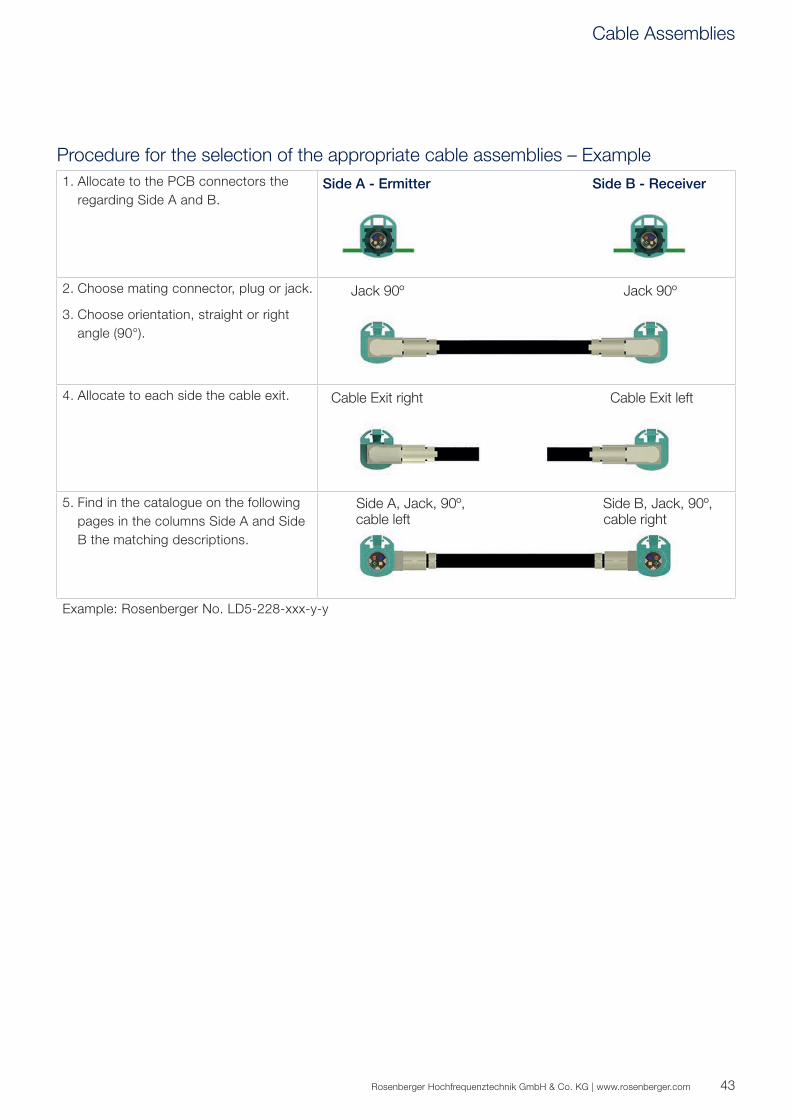
Procedure for the selection of the appropriate cable assemblies – Example1. Allocate to the PCB connectors the
regarding Side A and B.Side A - Ermitter Side B - Receiver
2. Choose mating connector, plug or jack.
3. Choose orientation, straight or right angle (90°).
Jack 90º Jack 90º
4. Allocate to each side the cable exit. Cable Exit right Cable Exit left
5. Find in the catalogue on the following pages in the columns Side A and Side B the matching descriptions.
Side A, Jack, 90º, cable left Side B, Jack, 90º, cable rightSide A, Jack, 90º, cable left Side B, Jack, 90º, cable rightSide A, Jack, 90º, cable left Side B, Jack, 90º, cable rightSide A, Jack, 90º, cable left Side B, Jack, 90º, cable rightSide A, Jack, 90º, cable left Side B, Jack, 90º, cable right
Example: Rosenberger No. LD5-228-xxx-y-y
Cable Assemblies
44
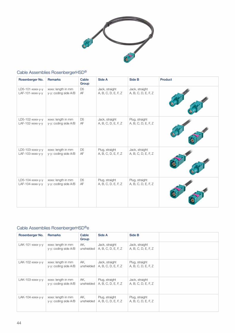
Cable Assemblies RosenbergerHSD®
Rosenberger No. Remarks Cable Group
Side A Side B Product
LD5-101-xxxx-y-yLAF-101-xxxx-y-y
xxxx: length in mmy-y: coding side A/B
D5AF
Jack, straightA, B, C, D, E, F, Z
Jack, straightA, B, C, D, E, F, Z
LD5-102-xxxx-y-yLAF-102-xxxx-y-y
xxxx: length in mmy-y: coding side A/B
D5AF
Jack, straightA, B, C, D, E, F, Z
Plug, straightA, B, C, D, E, F, Z
LD5-103-xxxx-y-yLAF-103-xxxx-y-y
xxxx: length in mmy-y: coding side A/B
D5AF
Plug, straightA, B, C, D, E, F, Z
Jack, straightA, B, C, D, E, F, Z
LD5-104-xxxx-y-yLAF-104-xxxx-y-y
xxxx: length in mmy-y: coding side A/B
D5AF
Plug, straightA, B, C, D, E, F, Z
Plug, straightA, B, C, D, E, F, Z
Cable Assemblies RosenbergerHSD®e
Rosenberger No. Remarks Cable Group
Side A Side B
LAK-101-xxxx-y-y xxxx: length in mmy-y: coding side A/B
AK, unshielded
Jack, straightA, B, C, D, E, F, Z
Jack, straightA, B, C, D, E, F, Z
LAK-102-xxxx-y-y xxxx: length in mmy-y: coding side A/B
AK, unshielded
Jack, straightA, B, C, D, E, F, Z
Plug, straightA, B, C, D, E, F, Z
LAK-103-xxxx-y-y xxxx: length in mmy-y: coding side A/B
AK, unshielded
Plug, straightA, B, C, D, E, F, Z
Jack, straightA, B, C, D, E, F, Z
LAK-104-xxxx-y-y xxxx: length in mmy-y: coding side A/B
AK, unshielded
Plug, straightA, B, C, D, E, F, Z
Plug, straightA, B, C, D, E, F, Z
45Rosenberger Hochfrequenztechnik GmbH & Co. KG | www.rosenberger.com
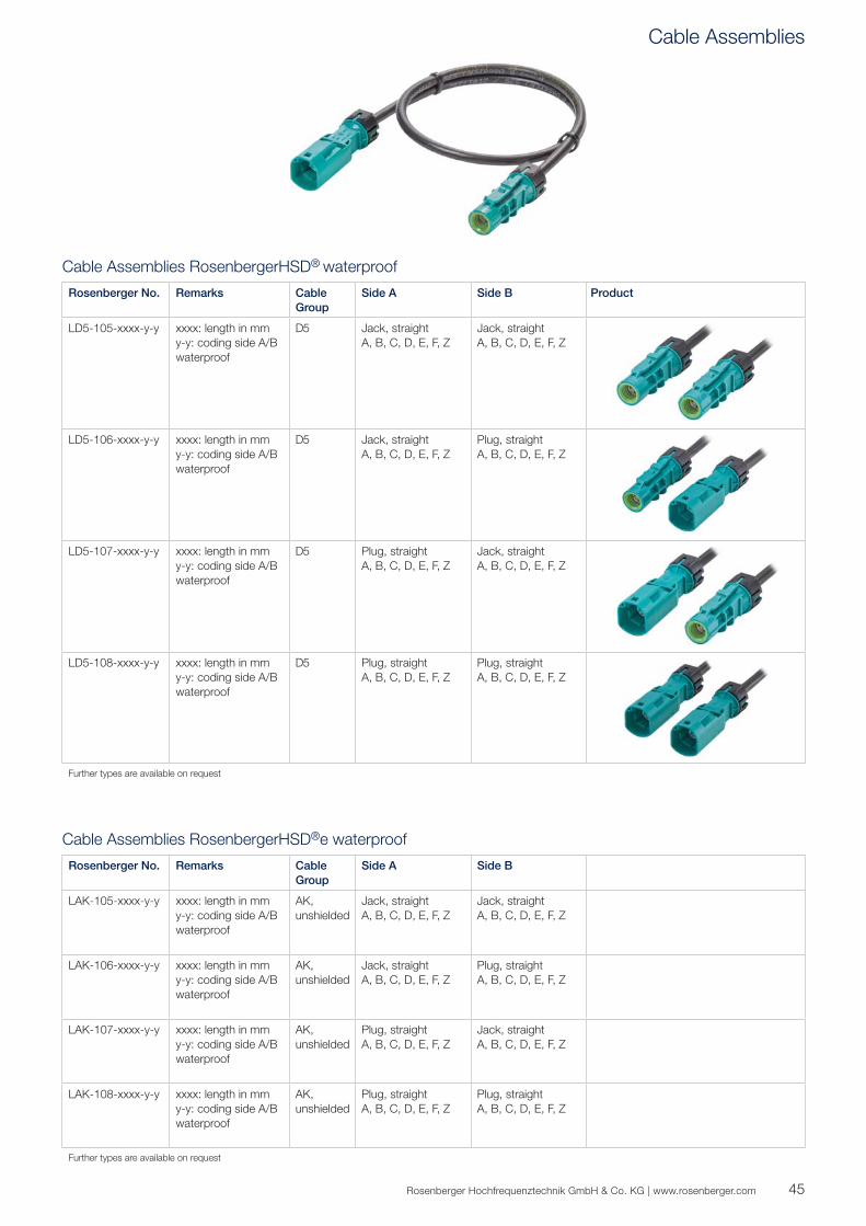
Cable Assemblies RosenbergerHSD® waterproof
Rosenberger No. Remarks Cable Group
Side A Side B Product
LD5-105-xxxx-y-y xxxx: length in mmy-y: coding side A/Bwaterproof
D5 Jack, straightA, B, C, D, E, F, Z
Jack, straightA, B, C, D, E, F, Z
LD5-106-xxxx-y-y xxxx: length in mmy-y: coding side A/Bwaterproof
D5 Jack, straightA, B, C, D, E, F, Z
Plug, straightA, B, C, D, E, F, Z
LD5-107-xxxx-y-y xxxx: length in mmy-y: coding side A/Bwaterproof
D5 Plug, straightA, B, C, D, E, F, Z
Jack, straightA, B, C, D, E, F, Z
LD5-108-xxxx-y-y xxxx: length in mmy-y: coding side A/Bwaterproof
D5 Plug, straightA, B, C, D, E, F, Z
Plug, straightA, B, C, D, E, F, Z
Further types are available on request
Cable Assemblies RosenbergerHSD®e waterproof
Rosenberger No. Remarks Cable Group
Side A Side B
LAK-105-xxxx-y-y xxxx: length in mmy-y: coding side A/Bwaterproof
AK, unshielded
Jack, straightA, B, C, D, E, F, Z
Jack, straightA, B, C, D, E, F, Z
LAK-106-xxxx-y-y xxxx: length in mmy-y: coding side A/Bwaterproof
AK, unshielded
Jack, straightA, B, C, D, E, F, Z
Plug, straightA, B, C, D, E, F, Z
LAK-107-xxxx-y-y xxxx: length in mmy-y: coding side A/Bwaterproof
AK, unshielded
Plug, straightA, B, C, D, E, F, Z
Jack, straightA, B, C, D, E, F, Z
LAK-108-xxxx-y-y xxxx: length in mmy-y: coding side A/Bwaterproof
AK, unshielded
Plug, straightA, B, C, D, E, F, Z
Plug, straightA, B, C, D, E, F, Z
Further types are available on request
Cable Assemblies
46
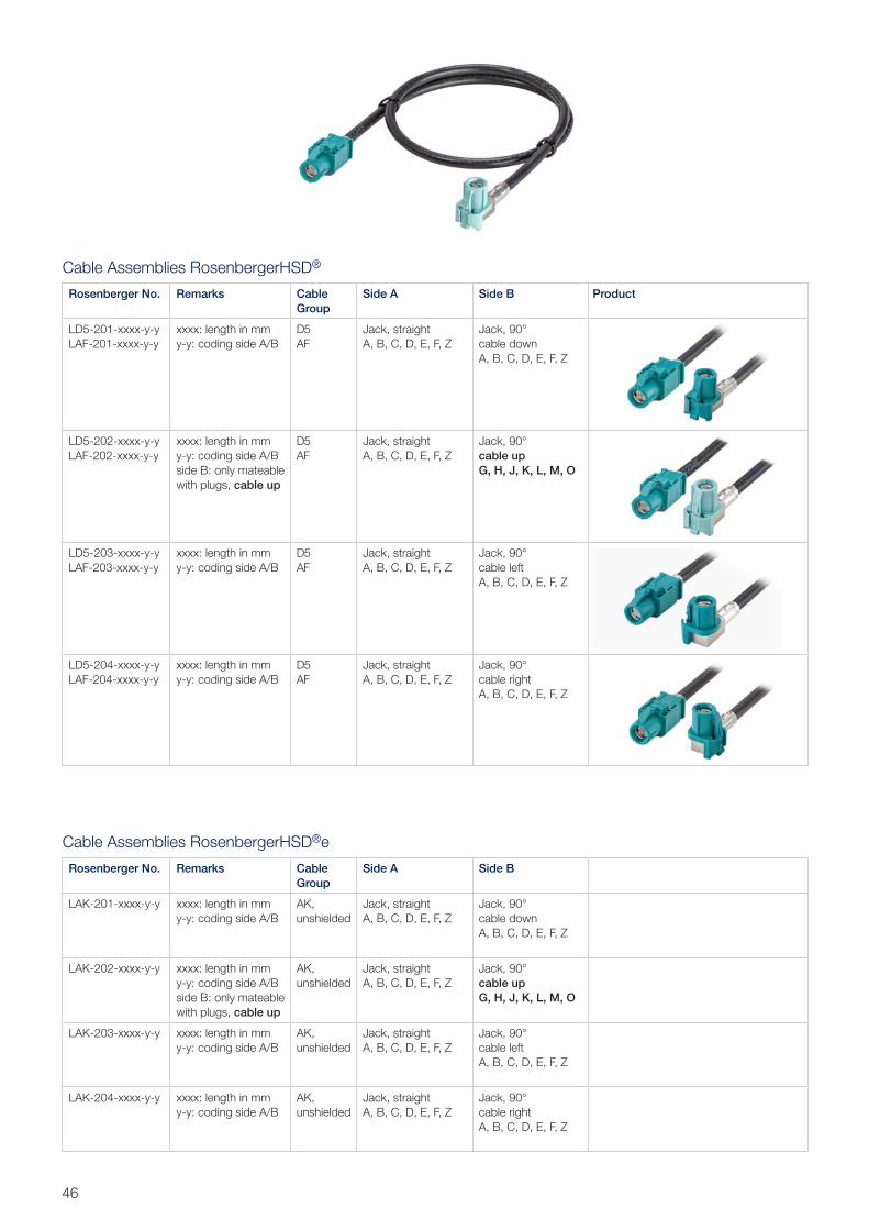
Cable Assemblies RosenbergerHSD®
Rosenberger No. Remarks Cable Group
Side A Side B Product
LD5-201-xxxx-y-yLAF-201-xxxx-y-y
xxxx: length in mmy-y: coding side A/B
D5AF
Jack, straightA, B, C, D, E, F, Z
Jack, 90°cable downA, B, C, D, E, F, Z
LD5-202-xxxx-y-yLAF-202-xxxx-y-y
xxxx: length in mmy-y: coding side A/B side B: only mateable with plugs, cable up
D5AF
Jack, straightA, B, C, D, E, F, Z
Jack, 90°cable upG, H, J, K, L, M, O
LD5-203-xxxx-y-yLAF-203-xxxx-y-y
xxxx: length in mmy-y: coding side A/B
D5AF
Jack, straightA, B, C, D, E, F, Z
Jack, 90°cable leftA, B, C, D, E, F, Z
LD5-204-xxxx-y-yLAF-204-xxxx-y-y
xxxx: length in mmy-y: coding side A/B
D5AF
Jack, straightA, B, C, D, E, F, Z
Jack, 90°cable rightA, B, C, D, E, F, Z
Cable Assemblies RosenbergerHSD®e
Rosenberger No. Remarks Cable Group
Side A Side B
LAK-201-xxxx-y-y xxxx: length in mmy-y: coding side A/B
AK, unshielded
Jack, straightA, B, C, D, E, F, Z
Jack, 90°cable downA, B, C, D, E, F, Z
LAK-202-xxxx-y-y xxxx: length in mmy-y: coding side A/B side B: only mateable with plugs, cable up
AK, unshielded
Jack, straightA, B, C, D, E, F, Z
Jack, 90°cable upG, H, J, K, L, M, O
LAK-203-xxxx-y-y xxxx: length in mmy-y: coding side A/B
AK, unshielded
Jack, straightA, B, C, D, E, F, Z
Jack, 90°cable leftA, B, C, D, E, F, Z
LAK-204-xxxx-y-y xxxx: length in mmy-y: coding side A/B
AK, unshielded
Jack, straightA, B, C, D, E, F, Z
Jack, 90°cable rightA, B, C, D, E, F, Z
47Rosenberger Hochfrequenztechnik GmbH & Co. KG | www.rosenberger.com
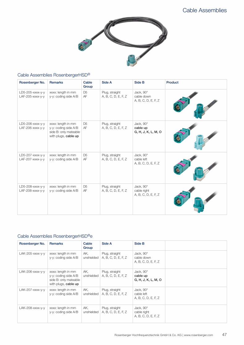
Cable Assemblies RosenbergerHSD®
Rosenberger No. Remarks Cable Group
Side A Side B Product
LD5-205-xxxx-y-yLAF-205-xxxx-y-y
xxxx: length in mmy-y: coding side A/B
D5AF
Plug, straightA, B, C, D, E, F, Z
Jack, 90°cable downA, B, C, D, E, F, Z
LD5-206-xxxx-y-yLAF-206-xxxx-y-y
xxxx: length in mmy-y: coding side A/B side B: only mateable with plugs, cable up
D5AF
Plug, straightA, B, C, D, E, F, Z
Jack, 90°cable upG, H, J, K, L, M, O
LD5-207-xxxx-y-yLAF-207-xxxx-y-y
xxxx: length in mmy-y: coding side A/B
D5AF
Plug, straightA, B, C, D, E, F, Z
Jack, 90°cable leftA, B, C, D, E, F, Z
LD5-208-xxxx-y-yLAF-208-xxxx-y-y
xxxx: length in mmy-y: coding side A/B
D5AF
Plug, straightA, B, C, D, E, F, Z
Jack, 90°cable rightA, B, C, D, E, F, Z
Cable Assemblies RosenbergerHSD®e
Rosenberger No. Remarks Cable Group
Side A Side B
LAK-205-xxxx-y-y xxxx: length in mmy-y: coding side A/B
AK, unshielded
Plug, straightA, B, C, D, E, F, Z
Jack, 90°cable downA, B, C, D, E, F, Z
LAK-206-xxxx-y-y xxxx: length in mmy-y: coding side A/B side B: only mateable with plugs, cable up
AK, unshielded
Plug, straightA, B, C, D, E, F, Z
Jack, 90°cable upG, H, J, K, L, M, O
LAK-207-xxxx-y-y xxxx: length in mmy-y: coding side A/B
AK, unshielded
Plug, straightA, B, C, D, E, F, Z
Jack, 90°cable leftA, B, C, D, E, F, Z
LAK-208-xxxx-y-y xxxx: length in mmy-y: coding side A/B
AK, unshielded
Plug, straightA, B, C, D, E, F, Z
Jack, 90°cable rightA, B, C, D, E, F, Z
Cable Assemblies
48
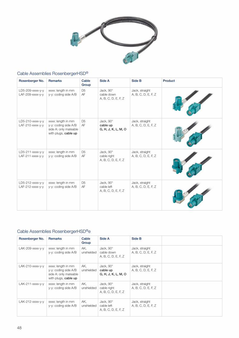
Cable Assemblies RosenbergerHSD®
Rosenberger No. Remarks Cable Group
Side A Side B Product
LD5-209-xxxx-y-yLAF-209-xxxx-y-y
xxxx: length in mmy-y: coding side A/B
D5AF
Jack, 90°cable downA, B, C, D, E, F, Z
Jack, straightA, B, C, D, E, F, Z
LD5-210-xxxx-y-yLAF-210-xxxx-y-y
xxxx: length in mmy-y: coding side A/B side A: only mateable with plugs, cable up
D5AF
Jack, 90°cable upG, H, J, K, L, M, O
Jack, straightA, B, C, D, E, F, Z
LD5-211-xxxx-y-yLAF-211-xxxx-y-y
xxxx: length in mmy-y: coding side A/B
D5AF
Jack, 90°cable rightA, B, C, D, E, F, Z
Jack, straightA, B, C, D, E, F, Z
LD5-212-xxxx-y-yLAF-212-xxxx-y-y
xxxx: length in mmy-y: coding side A/B
D5AF
Jack, 90°cable leftA, B, C, D, E, F, Z
Jack, straightA, B, C, D, E, F, Z
Cable Assemblies RosenbergerHSD®e
Rosenberger No. Remarks Cable Group
Side A Side B
LAK-209-xxxx-y-y xxxx: length in mmy-y: coding side A/B
AK, unshielded
Jack, 90°cable downA, B, C, D, E, F, Z
Jack, straightA, B, C, D, E, F, Z
LAK-210-xxxx-y-y xxxx: length in mmy-y: coding side A/B side A: only mateable with plugs, cable up
AK, unshielded
Jack, 90°cable upG, H, J, K, L, M, O
Jack, straightA, B, C, D, E, F, Z
LAK-211-xxxx-y-y xxxx: length in mmy-y: coding side A/B
AK, unshielded
Jack, 90°cable rightA, B, C, D, E, F, Z
Jack, straightA, B, C, D, E, F, Z
LAK-212-xxxx-y-y xxxx: length in mmy-y: coding side A/B
AK, unshielded
Jack, 90°cable leftA, B, C, D, E, F, Z
Jack, straightA, B, C, D, E, F, Z
49Rosenberger Hochfrequenztechnik GmbH & Co. KG | www.rosenberger.com
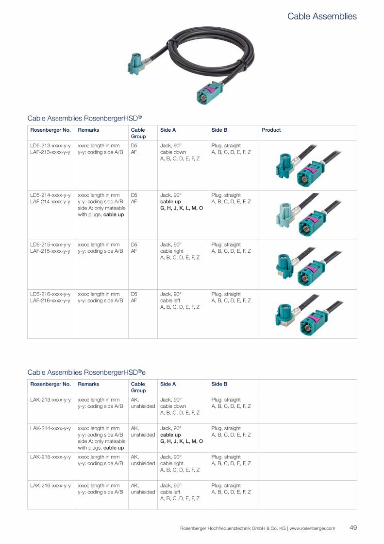
Cable Assemblies RosenbergerHSD®
Rosenberger No. Remarks Cable Group
Side A Side B Product
LD5-213-xxxx-y-yLAF-213-xxxx-y-y
xxxx: length in mmy-y: coding side A/B
D5AF
Jack, 90°cable downA, B, C, D, E, F, Z
Plug, straightA, B, C, D, E, F, Z
LD5-214-xxxx-y-yLAF-214-xxxx-y-y
xxxx: length in mmy-y: coding side A/B side A: only mateable with plugs, cable up
D5AF
Jack, 90°cable upG, H, J, K, L, M, O
Plug, straightA, B, C, D, E, F, Z
LD5-215-xxxx-y-yLAF-215-xxxx-y-y
xxxx: length in mmy-y: coding side A/B
D5AF
Jack, 90°cable rightA, B, C, D, E, F, Z
Plug, straightA, B, C, D, E, F, Z
LD5-216-xxxx-y-yLAF-216-xxxx-y-y
xxxx: length in mmy-y: coding side A/B
D5AF
Jack, 90°cable leftA, B, C, D, E, F, Z
Plug, straightA, B, C, D, E, F, Z
Cable Assemblies RosenbergerHSD®e
Rosenberger No. Remarks Cable Group
Side A Side B
LAK-213-xxxx-y-y xxxx: length in mmy-y: coding side A/B
AK, unshielded
Jack, 90°cable downA, B, C, D, E, F, Z
Plug, straightA, B, C, D, E, F, Z
LAK-214-xxxx-y-y xxxx: length in mmy-y: coding side A/B side A: only mateable with plugs, cable up
AK, unshielded
Jack, 90°cable upG, H, J, K, L, M, O
Plug, straightA, B, C, D, E, F, Z
LAK-215-xxxx-y-y xxxx: length in mmy-y: coding side A/B
AK, unshielded
Jack, 90°cable rightA, B, C, D, E, F, Z
Plug, straightA, B, C, D, E, F, Z
LAK-216-xxxx-y-y xxxx: length in mmy-y: coding side A/B
AK, unshielded
Jack, 90°cable leftA, B, C, D, E, F, Z
Plug, straightA, B, C, D, E, F, Z
Cable Assemblies
50
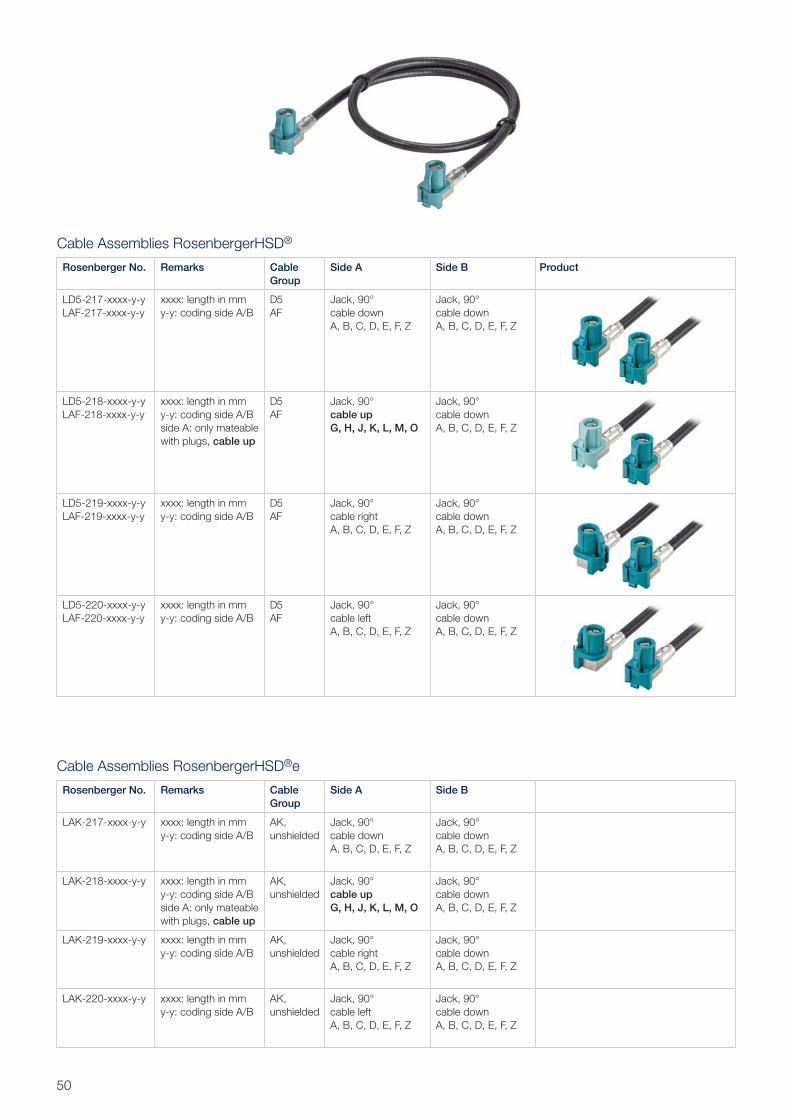
Cable Assemblies RosenbergerHSD®
Rosenberger No. Remarks Cable Group
Side A Side B Product
LD5-217-xxxx-y-yLAF-217-xxxx-y-y
xxxx: length in mmy-y: coding side A/B
D5AF
Jack, 90°cable downA, B, C, D, E, F, Z
Jack, 90°cable downA, B, C, D, E, F, Z
LD5-218-xxxx-y-yLAF-218-xxxx-y-y
xxxx: length in mmy-y: coding side A/B side A: only mateable with plugs, cable up
D5AF
Jack, 90°cable upG, H, J, K, L, M, O
Jack, 90°cable downA, B, C, D, E, F, Z
LD5-219-xxxx-y-yLAF-219-xxxx-y-y
xxxx: length in mmy-y: coding side A/B
D5AF
Jack, 90°cable rightA, B, C, D, E, F, Z
Jack, 90°cable downA, B, C, D, E, F, Z
LD5-220-xxxx-y-yLAF-220-xxxx-y-y
xxxx: length in mmy-y: coding side A/B
D5AF
Jack, 90°cable leftA, B, C, D, E, F, Z
Jack, 90°cable downA, B, C, D, E, F, Z
Cable Assemblies RosenbergerHSD®e
Rosenberger No. Remarks Cable Group
Side A Side B
LAK-217-xxxx-y-y xxxx: length in mmy-y: coding side A/B
AK, unshielded
Jack, 90°cable downA, B, C, D, E, F, Z
Jack, 90°cable downA, B, C, D, E, F, Z
LAK-218-xxxx-y-y xxxx: length in mmy-y: coding side A/B side A: only mateable with plugs, cable up
AK, unshielded
Jack, 90°cable upG, H, J, K, L, M, O
Jack, 90°cable downA, B, C, D, E, F, Z
LAK-219-xxxx-y-y xxxx: length in mmy-y: coding side A/B
AK, unshielded
Jack, 90°cable rightA, B, C, D, E, F, Z
Jack, 90°cable downA, B, C, D, E, F, Z
LAK-220-xxxx-y-y xxxx: length in mmy-y: coding side A/B
AK, unshielded
Jack, 90°cable leftA, B, C, D, E, F, Z
Jack, 90°cable downA, B, C, D, E, F, Z
51Rosenberger Hochfrequenztechnik GmbH & Co. KG | www.rosenberger.com
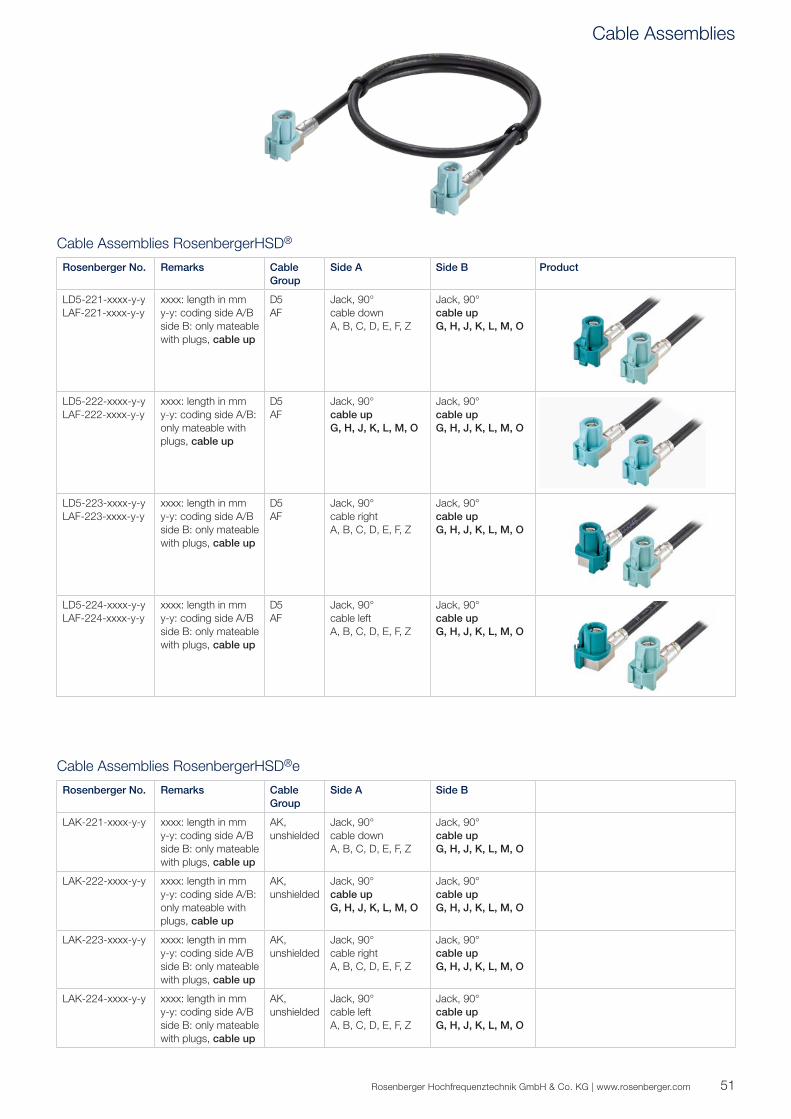
Cable Assemblies RosenbergerHSD®
Rosenberger No. Remarks Cable Group
Side A Side B Product
LD5-221-xxxx-y-yLAF-221-xxxx-y-y
xxxx: length in mmy-y: coding side A/Bside B: only mateable with plugs, cable up
D5AF
Jack, 90°cable downA, B, C, D, E, F, Z
Jack, 90°cable upG, H, J, K, L, M, O
LD5-222-xxxx-y-yLAF-222-xxxx-y-y
xxxx: length in mmy-y: coding side A/B: only mateable with plugs, cable up
D5AF
Jack, 90°cable upG, H, J, K, L, M, O
Jack, 90°cable upG, H, J, K, L, M, O
LD5-223-xxxx-y-yLAF-223-xxxx-y-y
xxxx: length in mmy-y: coding side A/Bside B: only mateable with plugs, cable up
D5AF
Jack, 90°cable rightA, B, C, D, E, F, Z
Jack, 90°cable upG, H, J, K, L, M, O
LD5-224-xxxx-y-yLAF-224-xxxx-y-y
xxxx: length in mmy-y: coding side A/Bside B: only mateable with plugs, cable up
D5AF
Jack, 90°cable leftA, B, C, D, E, F, Z
Jack, 90°cable upG, H, J, K, L, M, O
Cable Assemblies RosenbergerHSD®e
Rosenberger No. Remarks Cable Group
Side A Side B
LAK-221-xxxx-y-y xxxx: length in mmy-y: coding side A/Bside B: only mateable with plugs, cable up
AK, unshielded
Jack, 90°cable downA, B, C, D, E, F, Z
Jack, 90°cable upG, H, J, K, L, M, O
LAK-222-xxxx-y-y xxxx: length in mmy-y: coding side A/B: only mateable with plugs, cable up
AK, unshielded
Jack, 90°cable upG, H, J, K, L, M, O
Jack, 90°cable upG, H, J, K, L, M, O
LAK-223-xxxx-y-y xxxx: length in mmy-y: coding side A/Bside B: only mateable with plugs, cable up
AK, unshielded
Jack, 90°cable rightA, B, C, D, E, F, Z
Jack, 90°cable upG, H, J, K, L, M, O
LAK-224-xxxx-y-y xxxx: length in mmy-y: coding side A/Bside B: only mateable with plugs, cable up
AK, unshielded
Jack, 90°cable leftA, B, C, D, E, F, Z
Jack, 90°cable upG, H, J, K, L, M, O
Cable Assemblies
52
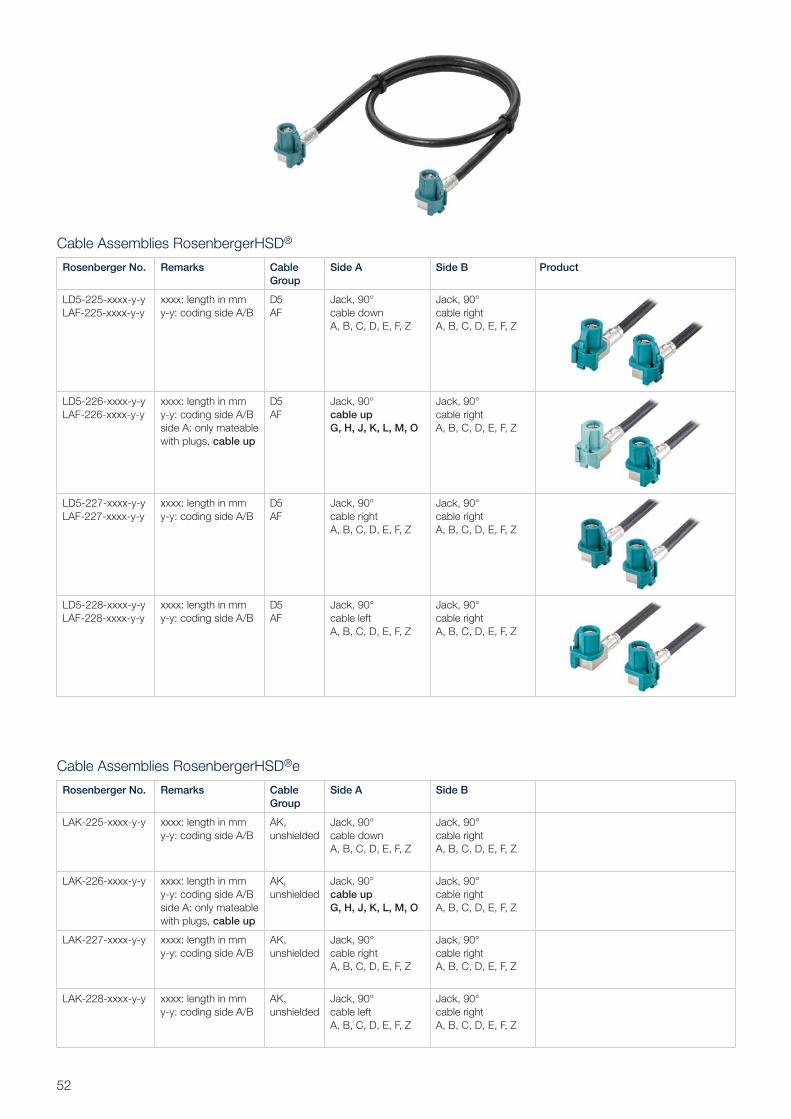
Cable Assemblies RosenbergerHSD®
Rosenberger No. Remarks Cable Group
Side A Side B Product
LD5-225-xxxx-y-yLAF-225-xxxx-y-y
xxxx: length in mmy-y: coding side A/B
D5AF
Jack, 90°cable downA, B, C, D, E, F, Z
Jack, 90°cable rightA, B, C, D, E, F, Z
LD5-226-xxxx-y-yLAF-226-xxxx-y-y
xxxx: length in mmy-y: coding side A/B side A: only mateable with plugs, cable up
D5AF
Jack, 90°cable upG, H, J, K, L, M, O
Jack, 90°cable rightA, B, C, D, E, F, Z
LD5-227-xxxx-y-yLAF-227-xxxx-y-y
xxxx: length in mmy-y: coding side A/B
D5AF
Jack, 90°cable rightA, B, C, D, E, F, Z
Jack, 90°cable rightA, B, C, D, E, F, Z
LD5-228-xxxx-y-yLAF-228-xxxx-y-y
xxxx: length in mmy-y: coding side A/B
D5AF
Jack, 90°cable leftA, B, C, D, E, F, Z
Jack, 90°cable rightA, B, C, D, E, F, Z
Cable Assemblies RosenbergerHSD®e
Rosenberger No. Remarks Cable Group
Side A Side B
LAK-225-xxxx-y-y xxxx: length in mmy-y: coding side A/B
AK, unshielded
Jack, 90°cable downA, B, C, D, E, F, Z
Jack, 90°cable rightA, B, C, D, E, F, Z
LAK-226-xxxx-y-y xxxx: length in mmy-y: coding side A/B side A: only mateable with plugs, cable up
AK, unshielded
Jack, 90°cable upG, H, J, K, L, M, O
Jack, 90°cable rightA, B, C, D, E, F, Z
LAK-227-xxxx-y-y xxxx: length in mmy-y: coding side A/B
AK, unshielded
Jack, 90°cable rightA, B, C, D, E, F, Z
Jack, 90°cable rightA, B, C, D, E, F, Z
LAK-228-xxxx-y-y xxxx: length in mmy-y: coding side A/B
AK, unshielded
Jack, 90°cable leftA, B, C, D, E, F, Z
Jack, 90°cable rightA, B, C, D, E, F, Z
53Rosenberger Hochfrequenztechnik GmbH & Co. KG | www.rosenberger.com
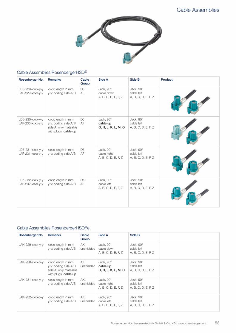
Cable Assemblies RosenbergerHSD®
Rosenberger No. Remarks Cable Group
Side A Side B Product
LD5-229-xxxx-y-yLAF-229-xxxx-y-y
xxxx: length in mmy-y: coding side A/B
D5AF
Jack, 90°cable downA, B, C, D, E, F, Z
Jack, 90°cable leftA, B, C, D, E, F, Z
LD5-230-xxxx-y-yLAF-230-xxxx-y-y
xxxx: length in mmy-y: coding side A/B side A: only mateable with plugs, cable up
D5AF
Jack, 90°cable upG, H, J, K, L, M, O
Jack, 90°cable leftA, B, C, D, E, F, Z
LD5-231-xxxx-y-yLAF-231-xxxx-y-y
xxxx: length in mmy-y: coding side A/B
D5AF
Jack, 90°cable rightA, B, C, D, E, F, Z
Jack, 90°cable leftA, B, C, D, E, F, Z
LD5-232-xxxx-y-yLAF-232-xxxx-y-y
xxxx: length in mmy-y: coding side A/B
D5AF
Jack, 90°cable leftA, B, C, D, E, F, Z
Jack, 90°cable leftA, B, C, D, E, F, Z
Cable Assemblies RosenbergerHSD®e
Rosenberger No. Remarks Cable Group
Side A Side B
LAK-229-xxxx-y-y xxxx: length in mmy-y: coding side A/B
AK, unshielded
Jack, 90°cable downA, B, C, D, E, F, Z
Jack, 90°cable leftA, B, C, D, E, F, Z
LAK-230-xxxx-y-y xxxx: length in mmy-y: coding side A/B side A: only mateable with plugs, cable up
AK, unshielded
Jack, 90°cable upG, H, J, K, L, M, O
Jack, 90°cable leftA, B, C, D, E, F, Z
LAK-231-xxxx-y-y xxxx: length in mmy-y: coding side A/B
AK, unshielded
Jack, 90°cable rightA, B, C, D, E, F, Z
Jack, 90°cable leftA, B, C, D, E, F, Z
LAK-232-xxxx-y-y xxxx: length in mmy-y: coding side A/B
AK, unshielded
Jack, 90°cable leftA, B, C, D, E, F, Z
Jack, 90°cable leftA, B, C, D, E, F, Z
Cable Assemblies
54
Technical References
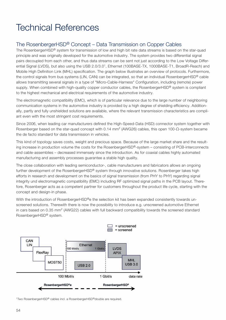
The RosenbergerHSD® Concept – Data Transmission on Copper CablesThe RosenbergerHSD® system for transmission of low and high bit rate data streams is based on the star-quad principle and was originally developed for the automotive industry. The system provides two differential signal pairs decoupled from each other, and thus data streams can be sent not just according to the Low Voltage Differ-ential Signal (LVDS), but also using the USB 2.0/3.01, Ethernet (100BASE-TX, 1000BASE-T1, BroadR-Reach) and Mobile High Definition Link (MHL) specification. The graph below illustrates an overview of protocols. Furthermore, the control signals from bus systems (LIN, CAN) can be integrated, so that an individual RosenbergerHSD® cable allows transmitting several signals in a type of "Micro-Cable-Harness" Configuration, including (remote) power supply. When combined with high-quality copper conductor cables, the RosenbergerHSD® system is compliant to the highest mechanical and electrical requirements of the automotive industry.
The electromagnetic compatibility (EMC), which is of particular relevance due to the large number of neighboring communication systems in the automotive industry is provided by a high degree of shielding efficiency. Addition-ally, partly and fully unshielded solutions are available, where the relevant transmission characteristics are compli-ant even with the most stringent cost requirements.
Since 2006, when leading car manufacturers defined the High-Speed-Data (HSD) connector system together with Rosenberger based on the star-quad concept with 0.14 mm² (AWG26) cables, this open 100-Ω-system became the de facto standard for data transmission in vehicles.
This kind of topology saves costs, weight and precious space. Because of the large market share and the result-ing increase in production volume the costs for the RosenbergerHSD®-system – consisting of PCB-interconnects and cable-assemblies – decreased immensely since the introduction. As for coaxial cables highly automated manufacturing and assembly processes guarantee a stable high quality.
The close collaboration with leading semiconductor-, cable manufacturers and fabricators allows an ongoing further development of the RosenbergerHSD® system through innovative solutions. Rosenberger takes high efforts in research and development on the basics of signal transmission (from PHY to PHY) regarding signal integrity und electromagnetic compatibility (EMC) including RF optimized signal paths in the PCB layout. There-fore, Rosenberger acts as a competent partner for customers throughout the product life cycle, starting with the concept and design-in phase.
With the introduction of RosenbergerHSD®e the selection kit has been expanded consistently towards un-screened solutions. Therewith there is now the possibility to introduce e.g. unscreened automotive Ethernet in cars based on 0.35 mm² (AWG22) cables with full backward compatibility towards the screened standard RosenbergerHSD® system.
1Two RosenbergerHSD® cables incl. a RosenbergerHSD®double are required.
1
2
1
2
4
3
55Rosenberger Hochfrequenztechnik GmbH & Co. KG | www.rosenberger.com
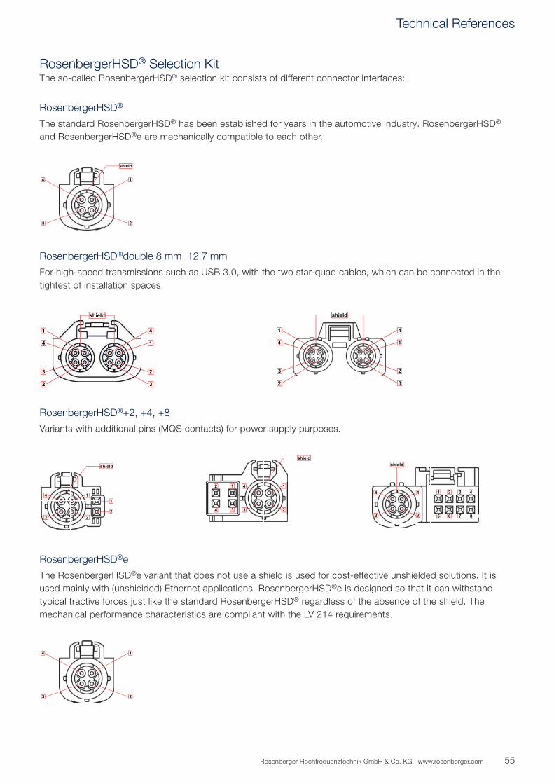
RosenbergerHSD® Selection KitThe so-called RosenbergerHSD® selection kit consists of different connector interfaces:
RosenbergerHSD®
The standard RosenbergerHSD® has been established for years in the automotive industry. RosenbergerHSD® and RosenbergerHSD®e are mechanically compatible to each other.
RosenbergerHSD®+2, +4, +8
Variants with additional pins (MQS contacts) for power supply purposes.
RosenbergerHSD®double 8 mm, 12.7 mm
For high-speed transmissions such as USB 3.0, with the two star-quad cables, which can be connected in the tightest of installation spaces.
RosenbergerHSD®e
The RosenbergerHSD®e variant that does not use a shield is used for cost- effective unshielded solutions. It is used mainly with (unshielded) Ethernet applications. RosenbergerHSD®e is designed so that it can withstand typical tractive forces just like the standard RosenbergerHSD® regardless of the absence of the shield. The mechanical performance characteristics are compliant with the LV 214 requirements.
Technical References
56
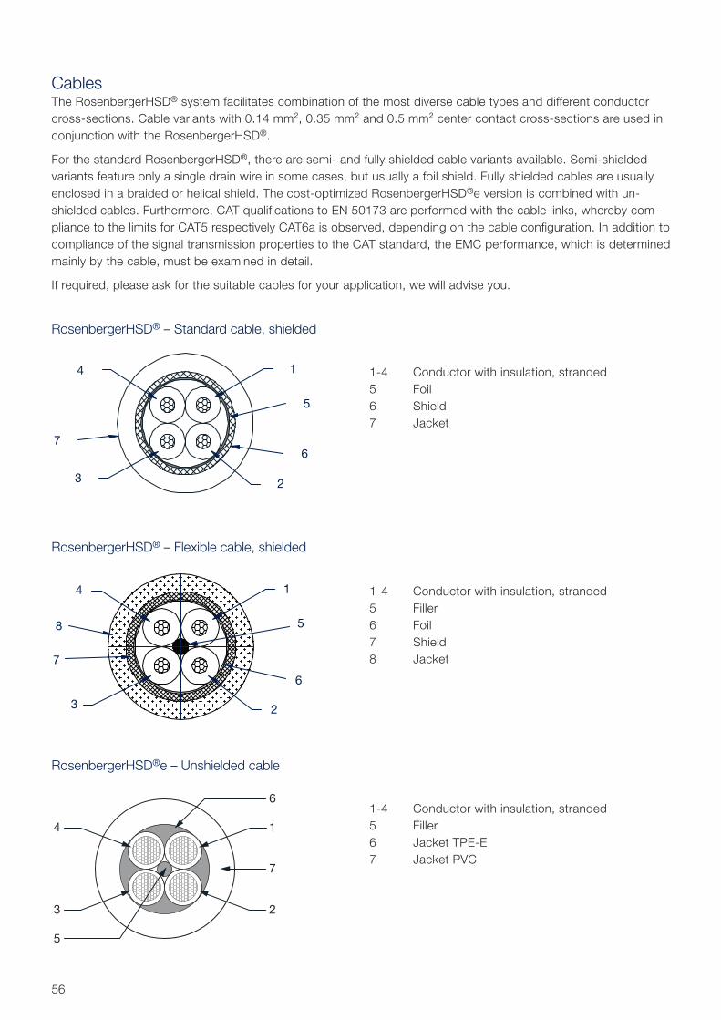
CablesThe RosenbergerHSD® system facilitates combination of the most diverse cable types and different conductor cross-sections. Cable variants with 0.14 mm², 0.35 mm² and 0.5 mm² center contact cross-sections are used in conjunction with the RosenbergerHSD®.
For the standard RosenbergerHSD®, there are semi- and fully shielded cable variants available. Semi-shielded variants feature only a single drain wire in some cases, but usually a foil shield. Fully shielded cables are usually enclosed in a braided or helical shield. The cost-optimized RosenbergerHSD®e version is combined with un-shielded cables. Furthermore, CAT qualifications to EN 50173 are performed with the cable links, whereby com-pliance to the limits for CAT5 respectively CAT6a is observed, depending on the cable configuration. In addition to compliance of the signal transmission properties to the CAT standard, the EMC performance, which is determined mainly by the cable, must be examined in detail.
If required, please ask for the suitable cables for your application, we will advise you.
RosenbergerHSD® – Standard cable, shielded
RosenbergerHSD® – Flexible cable, shielded
RosenbergerHSD®e – Unshielded cable
1-4 Conductor with insulation, stranded 5 Foil 6 Shield 7 Jacket
1-4 Conductor with insulation, stranded 5 Filler 6 Foil 7 Shield 8 Jacket
1-4 Conductor with insulation, stranded 5 Filler 6 Jacket TPE-E 7 Jacket PVC
57Rosenberger Hochfrequenztechnik GmbH & Co. KG | www.rosenberger.com
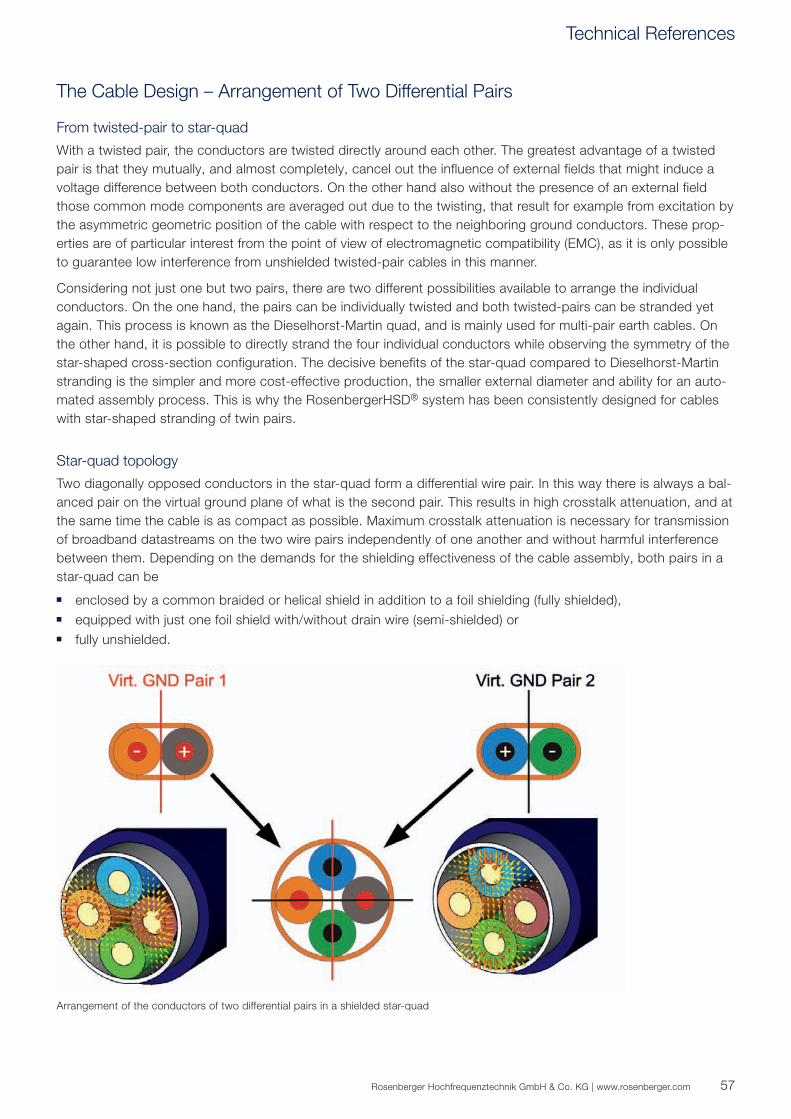
The Cable Design – Arrangement of Two Differential Pairs
From twisted-pair to star-quad
With a twisted pair, the conductors are twisted directly around each other. The greatest advantage of a twisted pair is that they mutually, and almost completely, cancel out the influence of external fields that might induce a voltage difference between both conductors. On the other hand also without the presence of an external field those common mode components are averaged out due to the twisting, that result for example from excitation by the asymmetric geometric position of the cable with respect to the neighboring ground conductors. These prop-erties are of particular interest from the point of view of electromagnetic compatibility (EMC), as it is only possible to guarantee low interference from unshielded twisted-pair cables in this manner.
Considering not just one but two pairs, there are two different possibilities available to arrange the individual conductors. On the one hand, the pairs can be individually twisted and both twisted-pairs can be stranded yet again. This process is known as the Dieselhorst-Martin quad, and is mainly used for multi-pair earth cables. On the other hand, it is possible to directly strand the four individual conductors while observing the symmetry of the star-shaped cross-section configuration. The decisive benefits of the star-quad compared to Dieselhorst-Martin stranding is the simpler and more cost-effective production, the smaller external diameter and ability for an auto-mated assembly process. This is why the RosenbergerHSD® system has been consistently designed for cables with star-shaped stranding of twin pairs.
Star-quad topology
Two diagonally opposed conductors in the star-quad form a differential wire pair. In this way there is always a bal-anced pair on the virtual ground plane of what is the second pair. This results in high crosstalk attenuation, and at the same time the cable is as compact as possible. Maximum crosstalk attenuation is necessary for transmission of broadband datastreams on the two wire pairs independently of one another and without harmful interference between them. Depending on the demands for the shielding effectiveness of the cable assembly, both pairs in a star-quad can be
enclosed by a common braided or helical shield in addition to a foil shielding (fully shielded), equipped with just one foil shield with/without drain wire (semi-shielded) or fully unshielded.
Arrangement of the conductors of two differential pairs in a shielded star-quad
Technical References
1
2
1
2
4
3
58
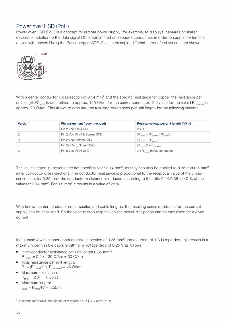
Power over HSD (PoH)Power over HSD (PoH) is a concept for remote power supply, for example, to displays, cameras or similar devices. In addition to the data signal DC is transmitted on separate conductors in order to supply the terminal device with power. Using the RosenbergerHSD®+2 as an example, different current feed variants are shown.
With a center conductor cross-section of 0.14 mm² and the specific resistance for copper the resistance per unit length R'cond is determined to approx. 125 Ω/km for the center conductor. The value for the shield R'screen is approx. 20 Ω/km. This allows to calculate the resulting resistances per unit length for the following variants:
The values stated in the table are not specifically for 0.14 mm², as they can also be applied to 0.35 and 0.5 mm² inner conductor cross-sections. The conductor resistance is proportional to the reciprocal value of the cross- section, i.e. for 0.35 mm² the conductor resistance is reduced according to the ratio 0.14/0.35 to 40 % of the value for 0.14 mm². For 0.5 mm² it results in a value of 28 %.
With known center conductor cross-section and cable lengths, the resulting series resistance for the current supply can be calculated. So the voltage drop respectively the power dissipation can be calculated for a given current.
If e.g. case 4 with a inner conductor cross-section of 0.35 mm² and a current of 1 A is regarded, this results in a maximum permissible cable length for a voltage drop of 0.25 V as follows.
Inner conductor resistance per unit length 0.35 mm²: R'cond = 0.4 x 125 Ω/km = 50 Ω/km
Total resistance per unit length: R' = (R'cond/2 + R'screen) = 45 Ω/km
Maximum resistance: Rmax = ΔU/I = 0.25 Ω
Maximum length: lmax = Rmax/R' = 5.55 m
Version Pin assignment (recommended) Resistance load per unit length (Ω/km)
1 Pin 2 Vcc, Pin 4 GND 2 x R'cond
2 Pin 2 Vcc, Pin 4 & Screen GND (R'cond + R'screen || R'cond) 2
3 Pin 2 Vcc, Screen GND (R'cond + R'screen)
4 Pin 2+4 Vcc, Screen GND (R'cond/2 + R'screen)
5 Pin 5 Vcc, Pin 6 GND 2 x R'MQS (MQS conductor)
2"||" stands for parallel connection of resistors, i.e. X || Y = (X*Y)/(X+Y)
Vcc
GND
Vcc
GND
Derating Chart acc. to DIN EN 60512-5-2Test device D4S10A contacted with D4K10A at cable DACAR 535
Two wires of test device current loaded, maximum temperature 125°C
0
1
2
3
4
5
6
7
8
25 30 35 40 45 50 55 60 65 70 75 80 85 90 95 100 105 110 115 120 125 130
Ambient Temperature [°C]
Cur
rent
[A]
Derating Chart 80% Measured Chart Limit
59Rosenberger Hochfrequenztechnik GmbH & Co. KG | www.rosenberger.com
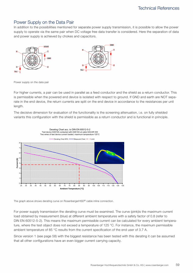
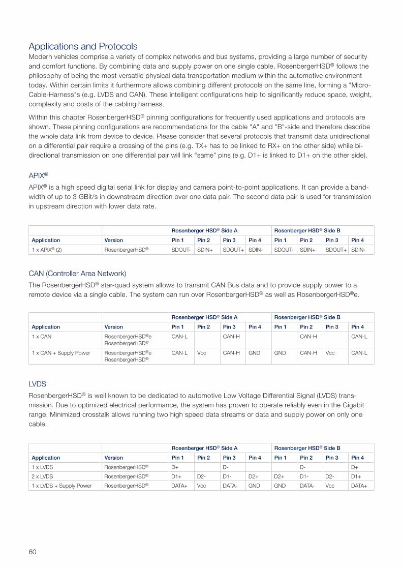
Power Supply on the Data PairIn addition to the possibilities mentioned for separate power supply transmission, it is possible to allow the power supply to operate via the same pair when DC voltage free data transfer is considered. Here the separation of data and power supply is achieved by chokes and capacitors.
For higher currents, a pair can be used in parallel as a feed conductor and the shield as a return conductor. This is permissible when the powered end device is isolated with respect to ground. If GND and earth are NOT sepa-rate in the end device, the return currents are split on the end device in accordance to the resistances per unit length.
The decisive dimension for evaluation of the functionality is the screening attenuation, i.e. on fully shielded variants this configuration with the shield is permissible as a return conductor and is functional in principle.
For power supply transmission the derating curve must be examined. The curve (pink)is the maximum current load obtained by measurement (blue) at different ambient temperatures with a safety factor of 0.8 (refer to DIN EN 60512-5-2). This means the maximum permissible current can be calculated for every ambient tempera-ture, where the test object does not exceed a temperature of 125 °C. For instance, the maximum permissible ambient temperature of 85 °C results from the current specification of the end user of 3.7 A.
Since version 1 (see page 58) with the biggest resistance has been tested with this derating it can be assumed that all other configurations have an even bigger current carrying capacity.
Power supply on the data pair
The graph above shows derating curve on RosenbergerHSD® cable inline connection.
Technical References
60
Applications and ProtocolsModern vehicles comprise a variety of complex networks and bus systems, providing a large number of security and comfort functions. By combining data and supply power on one single cable, RosenbergerHSD® follows the philosophy of being the most versatile physical data transportation medium within the automotive environment today. Within certain limits it furthermore allows combining different protocols on the same line, forming a "Micro-Cable-Harness"s (e.g. LVDS and CAN). These intelligent configurations help to significantly reduce space, weight, complexity and costs of the cabling harness.
Within this chapter RosenbergerHSD® pinning configurations for frequently used applications and protocols are shown. These pinning configurations are recommendations for the cable "A" and "B"-side and therefore describe the whole data link from device to device. Please consider that several protocols that transmit data unidirectional on a differential pair require a crossing of the pins (e.g. TX+ has to be linked to RX+ on the other side) while bi-directional transmission on one differential pair will link “same” pins (e.g. D1+ is linked to D1+ on the other side).
APIX®
APIX® is a high speed digital serial link for display and camera point-to-point applications. It can provide a band-width of up to 3 GBit/s in downstream direction over one data pair. The second data pair is used for transmission in upstream direction with lower data rate.
CAN (Controller Area Network)
The RosenbergerHSD® star-quad system allows to transmit CAN Bus data and to provide supply power to a remote device via a single cable. The system can run over RosenbergerHSD® as well as RosenbergerHSD®e.
LVDS
RosenbergerHSD® is well known to be dedicated to automotive Low Voltage Differential Signal (LVDS) trans-mission. Due to optimized electrical performance, the system has proven to operate reliably even in the Gigabit range. Minimized crosstalk allows running two high speed data streams or data and supply power on only one cable.
Rosenberger HSD® Side A Rosenberger HSD® Side B
Application Version Pin 1 Pin 2 Pin 3 Pin 4 Pin 1 Pin 2 Pin 3 Pin 4
1 x APIX® (2) RosenbergerHSD® SDOUT- SDIN+ SDOUT+ SDIN- SDOUT- SDIN+ SDOUT+ SDIN-
Rosenberger HSD® Side A Rosenberger HSD® Side B
Application Version Pin 1 Pin 2 Pin 3 Pin 4 Pin 1 Pin 2 Pin 3 Pin 4
1 x CAN RosenbergerHSD®e RosenbergerHSD®
CAN-L CAN-H CAN-H CAN-L
1 x CAN + Supply Power RosenbergerHSD®e RosenbergerHSD®
CAN-L Vcc CAN-H GND GND CAN-H Vcc CAN-L
Rosenberger HSD® Side A Rosenberger HSD® Side B
Application Version Pin 1 Pin 2 Pin 3 Pin 4 Pin 1 Pin 2 Pin 3 Pin 4
1 x LVDS RosenbergerHSD® D+ D- D- D+
2 x LVDS RosenbergerHSD® D1+ D2- D1- D2+ D2+ D1- D2- D1+
1 x LVDS + Supply Power RosenbergerHSD® DATA+ Vcc DATA- GND GND DATA- Vcc DATA+

61Rosenberger Hochfrequenztechnik GmbH & Co. KG | www.rosenberger.com
IEEE 1394 (Firewire)
RosenbergerHSD® is well suited for multimedia IEEE 1394 links. It is designed to transport video and audio with high bandwidth and assured quality of service.
Rosenberger HSD® Side A Rosenberger HSD® Side B
Application Version Pin 1 Pin 2 Pin 3 Pin 4 Pin 1 Pin 2 Pin 3 Pin 4
IEEE 1394 (Firewire) RosenbergerHSD® TPA+ TPB- TPA- TPB+ TPA+ TPB- TPA- TPB+
Rosenberger HSD® Side A Rosenberger HSD® Side B
Application Version Pin 1 Pin 2 Pin 3 Pin 4 Pin 1 Pin 2 Pin 3 Pin 4
1 x 1000BASE-T RosenbergerHSD®
doubleD1+ D2- D1- D2+ D2+ D1- D2- D1+
Pin 5 Pin 6 Pin 7 Pin 8 Pin 5 Pin 6 Pin 7 Pin 8
D3+ D4- D3- D4+ D4+ D3- D4- D3+
Rosenberger HSD® Side A Rosenberger HSD® Side B
Application Version Pin 1 Pin 2 Pin 3 Pin 4 Pin 1 Pin 2 Pin 3 Pin 4
1 x 100BASE-T RosenbergerHSD® TX+ RX- TX- RX+ TX+ RX- TX- RX+
1 x 100BASE-CX RosenbergerHSD® TX+ RX- TX- RX+ TX+ RX- TX- RX+
1 x BroadR-Reach (100BASE-T1)
RosenbergerHSD®e RosenbergerHSD®
D+ D- D- D+
2 x BroadR-Reach (100BASE-T1)
RosenbergerHSD®e RosenbergerHSD®
D1+ D2- D1- D2+ D2+ D1- D2- D1+
1 x 1000BASE-T1 RosenbergerHSD® D+ D- D- D+
IEEE 802.3 (Ethernet)
A large number of Ethernet protocols are supported by the RosenbergerHSD® system. This ranges from the widely implemented 100BASE-T standard, e.g. used for the diagnosis functions, to more demanding Gigabit links.
RosenbergerHSD® connectors are designed to meet the CAT6a requirements according to IEC 60603-7-51 for shielded RosenbergerHSD® connectors and IEC 60603-7-41 for unshielded RosenbergerHSD®e connectors. This ensures the customer to be prepared for current Fast Ethernet and future Gigabit automotive Ethernet application without the need to chance the connector interface.
To take full advantage of the star quad system, an automotive 100 MBit/s Ethernet link can be combined with DC for remote power supply of devices, e.g. cameras. This significantly reduces cost and complexity of the wiring harness.
Setting up an Ethernet link according to 1000BASE-T standard is also possible by means of a RosenbergerHSD® double connector. Therefore it is necessary to use two RosenbergerHSD® cables in parallel.
Technical References
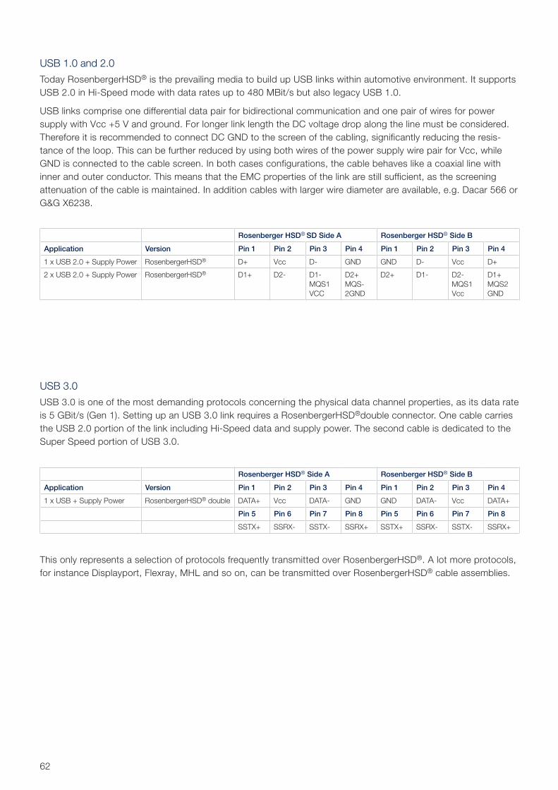
62
USB 1.0 and 2.0
Today RosenbergerHSD® is the prevailing media to build up USB links within automotive environment. It supports USB 2.0 in Hi-Speed mode with data rates up to 480 MBit/s but also legacy USB 1.0.
USB links comprise one differential data pair for bidirectional communication and one pair of wires for power supply with Vcc +5 V and ground. For longer link length the DC voltage drop along the line must be considered. Therefore it is recommended to connect DC GND to the screen of the cabling, significantly reducing the resis-tance of the loop. This can be further reduced by using both wires of the power supply wire pair for Vcc, while GND is connected to the cable screen. In both cases configurations, the cable behaves like a coaxial line with inner and outer conductor. This means that the EMC properties of the link are still sufficient, as the screening attenuation of the cable is maintained. In addition cables with larger wire diameter are available, e.g. Dacar 566 or G&G X6238.
USB 3.0
USB 3.0 is one of the most demanding protocols concerning the physical data channel properties, as its data rate is 5 GBit/s (Gen 1). Setting up an USB 3.0 link requires a RosenbergerHSD®double connector. One cable carries the USB 2.0 portion of the link including Hi-Speed data and supply power. The second cable is dedicated to the Super Speed portion of USB 3.0.
This only represents a selection of protocols frequently transmitted over RosenbergerHSD®. A lot more protocols, for instance Displayport, Flexray, MHL and so on, can be transmitted over RosenbergerHSD® cable assemblies.
Rosenberger HSD® SD Side A Rosenberger HSD® Side B
Application Version Pin 1 Pin 2 Pin 3 Pin 4 Pin 1 Pin 2 Pin 3 Pin 4
1 x USB 2.0 + Supply Power RosenbergerHSD® D+ Vcc D- GND GND D- Vcc D+
2 x USB 2.0 + Supply Power RosenbergerHSD® D1+ D2- D1-MQS1VCC
D2+MQS-2GND
D2+ D1- D2-MQS1Vcc
D1+MQS2GND
Rosenberger HSD® Side A Rosenberger HSD® Side B
Application Version Pin 1 Pin 2 Pin 3 Pin 4 Pin 1 Pin 2 Pin 3 Pin 4
1 x USB + Supply Power RosenbergerHSD® double DATA+ Vcc DATA- GND GND DATA- Vcc DATA+
Pin 5 Pin 6 Pin 7 Pin 8 Pin 5 Pin 6 Pin 7 Pin 8
SSTX+ SSRX- SSTX- SSRX+ SSTX+ SSRX- SSTX- SSRX+
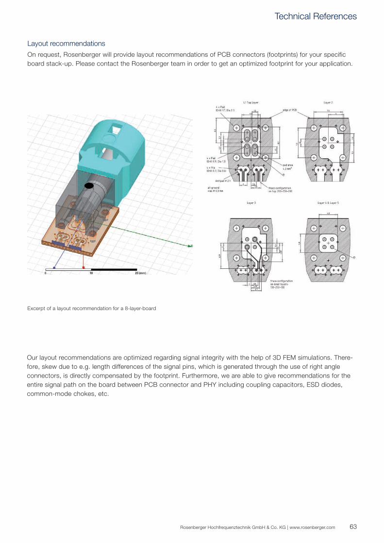
63Rosenberger Hochfrequenztechnik GmbH & Co. KG | www.rosenberger.com
Layout recommendations
On request, Rosenberger will provide layout recommendations of PCB connectors (footprints) for your specific board stack-up. Please contact the Rosenberger team in order to get an optimized footprint for your application.
Our layout recommendations are optimized regarding signal integrity with the help of 3D FEM simulations. There-fore, skew due to e.g. length differences of the signal pins, which is generated through the use of right angle connectors, is directly compensated by the footprint. Furthermore, we are able to give recommendations for the entire signal path on the board between PCB connector and PHY including coupling capacitors, ESD diodes, common-mode chokes, etc.
Excerpt of a layout recommendation for a 8-layer-board
Technical References
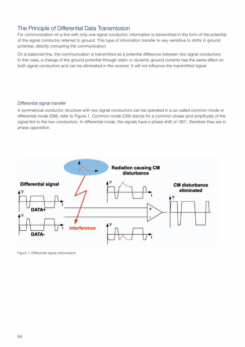
64
The Principle of Differential Data TransmissionFor communication on a line with only one signal conductor, information is trans mitted in the form of the potential of the signal conductor referred to ground. This type of information transfer is very sensitive to shifts in ground potential, directly corrupting the communication.
On a balanced line, the communication is transmitted as a potential difference between two signal conductors. In this case, a change of the ground potential through static or dynamic ground currents has the same effect on both signal conductors and can be eliminated in the receiver. It will not influence the transmitted signal.
Differential signal transfer
A symmetrical conductor structure with two signal conductors can be operated in a so-called common mode or differential mode (DM), refer to Figure 1. Common mode (CM) stands for a common phase (and amplitude) of the signal fed to the two conductors. In differential mode, the signals have a phase shift of 180°, therefore they are in phase opposition.
Figure 1: Differential signal transmission
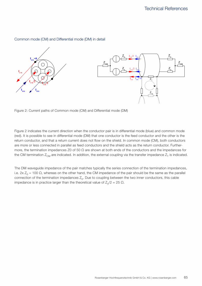
65Rosenberger Hochfrequenztechnik GmbH & Co. KG | www.rosenberger.com
Figure 2 indicates the current direction when the conductor pair is in differential mode (blue) and common mode (red). It is possible to see in differential mode (DM) that one conductor is the feed conductor and the other is the return conductor, and that a return current does not flow on the shield. In common mode (CM), both conductors are more or less connected in parallel as feed conductors and the shield acts as the return conductor. Further-more, the termination impedances Z0 of 50 Ω are shown at both ends of the conductors and the impedances for the CM termination ZCM are indicated. In addition, the external coupling via the transfer impedance ZT is indicated.
The DM waveguide impedance of the pair matches typically the series connection of the termination impedances, i.e. 2x Z0 = 100 Ω, whereas on the other hand, the CM impedance of the pair should be the same as the parallel connection of the termination impedances Z0. Due to coupling between the two inner conductors, this cable impedance is in practice larger than the theoretical value of Z0/2 = 25 Ω.
Common mode (CM) and Differential mode (DM) in detail
Figure 2: Current paths of Common mode (CM) and Differential mode (DM)
Technical References
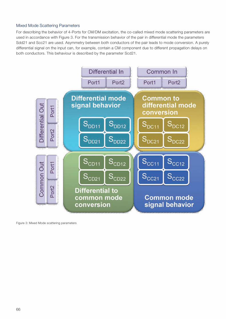
66
Mixed Mode Scattering Parameters
For describing the behavior of 4-Ports for CM/DM excitation, the co-called mixed mode scattering parameters are used in accordance with Figure 3. For the trans mission behavior of the pair in differential mode the parameters Sdd21 and Scc21 are used. Asymmetry between both conductors of the pair leads to mode conversion. A purely differential signal on the input can, for example, contain a CM component due to different propagation delays on both conductors. This behaviour is described by the parameter Scd21.
Figure 3: Mixed Mode scattering parameters
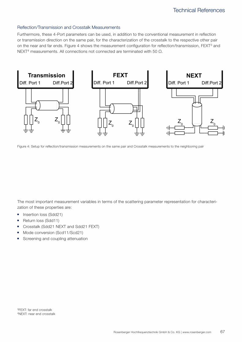
67Rosenberger Hochfrequenztechnik GmbH & Co. KG | www.rosenberger.com
3FEXT: far end crosstalk4NEXT: near end crosstalk
Reflection/Transmission and Crosstalk Measurements
Furthermore, these 4-Port parameters can be used, in addition to the conventional measurement in reflection or transmission direction on the same pair, for the characterization of the crosstalk to the respective other pair on the near and far ends. Figure 4 shows the measurement configuration for reflection/transmission, FEXT3 and NEXT4 measurements. All connections not connected are terminated with 50 Ω.
The most important measurement variables in terms of the scattering parameter representation for characteri-zation of these properties are:
Insertion loss (Sdd21) Return loss (Sdd11) Crosstalk (Sdd21 NEXT and Sdd21 FEXT) Mode conversion (Scd11/Scd21) Screening and coupling attenuation
Figure 4: Setup for reflection/transmission measurements on the same pair and Crosstalk measurements to the neighboring pair
Technical References
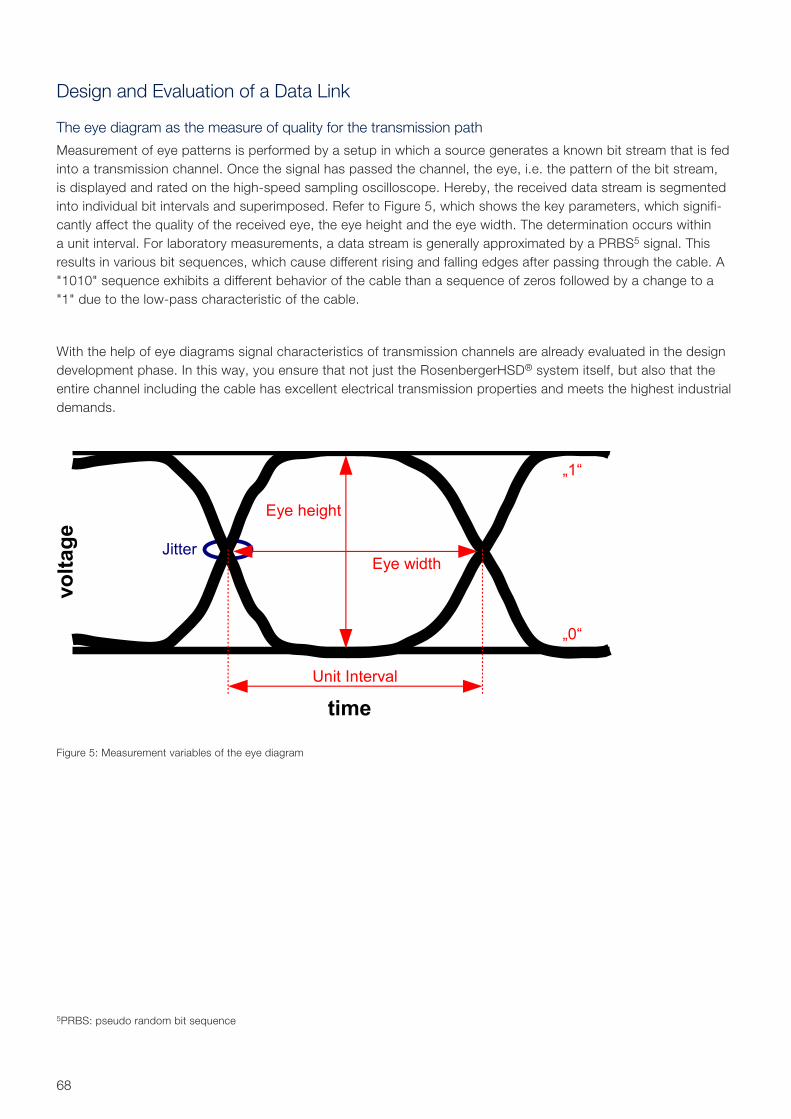
68
Design and Evaluation of a Data Link
The eye diagram as the measure of quality for the transmission path
Measurement of eye patterns is performed by a setup in which a source generates a known bit stream that is fed into a transmission channel. Once the signal has passed the channel, the eye, i.e. the pattern of the bit stream, is displayed and rated on the high-speed sampling oscilloscope. Hereby, the received data stream is segmented into individual bit intervals and super imposed. Refer to Figure 5, which shows the key parameters, which signifi-cantly affect the quality of the received eye, the eye height and the eye width. The determination occurs within a unit interval. For laboratory measurements, a data stream is generally approximated by a PRBS5 signal. This results in various bit sequences, which cause different rising and falling edges after passing through the cable. A "1010" sequence exhibits a different behavior of the cable than a sequence of zeros followed by a change to a "1" due to the low-pass characteristic of the cable.
With the help of eye diagrams signal characteristics of transmission channels are already evaluated in the design development phase. In this way, you ensure that not just the RosenbergerHSD® system itself, but also that the entire channel including the cable has excellent electrical transmission properties and meets the highest industrial demands.
Figure 5: Measurement variables of the eye diagram
5PRBS: pseudo random bit sequence
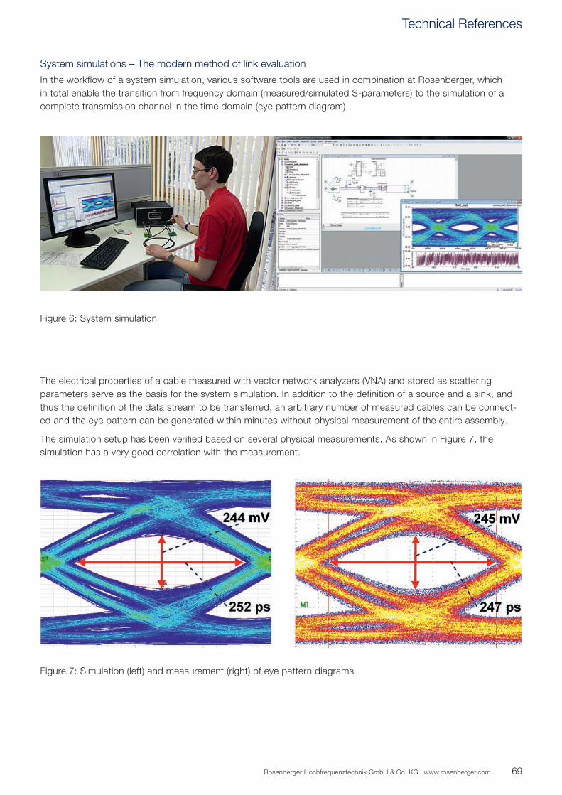
69Rosenberger Hochfrequenztechnik GmbH & Co. KG | www.rosenberger.com
The electrical properties of a cable measured with vector network analyzers (VNA) and stored as scattering parameters serve as the basis for the system simulation. In addition to the definition of a source and a sink, and thus the definition of the data stream to be transferred, an arbitrary number of measured cables can be connect-ed and the eye pattern can be generated within minutes without physical measurement of the entire assembly.
The simulation setup has been verified based on several physical measurements. As shown in Figure 7, the simulation has a very good correlation with the measurement.
System simulations – The modern method of link evaluation
In the workflow of a system simulation, various software tools are used in combination at Rosenberger, which in total enable the transition from frequency domain (measured/simulated S-parameters) to the simulation of a complete transmission channel in the time domain (eye pattern diagram).
Figure 6: System simulation
Figure 7: Simulation (left) and measurement (right) of eye pattern diagrams
Technical References
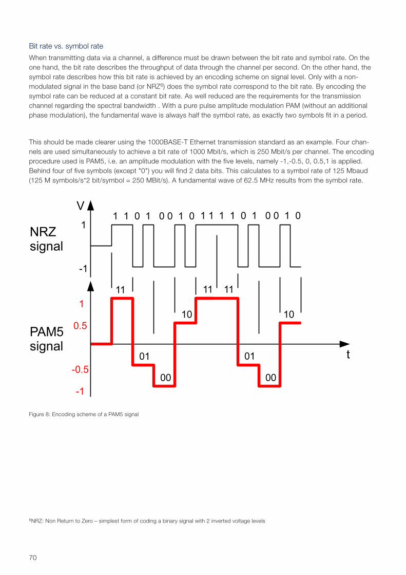
70
Bit rate vs. symbol rate
When transmitting data via a channel, a difference must be drawn between the bit rate and symbol rate. On the one hand, the bit rate describes the throughput of data through the channel per second. On the other hand, the symbol rate describes how this bit rate is achieved by an encoding scheme on signal level. Only with a non- modulated signal in the base band (or NRZ6) does the symbol rate correspond to the bit rate. By encoding the symbol rate can be reduced at a constant bit rate. As well reduced are the requirements for the transmission channel regarding the spectral bandwidth . With a pure pulse amplitude modulation PAM (without an additional phase modulation), the fundamental wave is always half the symbol rate, as exactly two symbols fit in a period.
This should be made clearer using the 1000BASE-T Ethernet transmission standard as an example. Four chan-nels are used simultaneously to achieve a bit rate of 1000 Mbit/s, which is 250 Mbit/s per channel. The encoding procedure used is PAM5, i.e. an amplitude modulation with the five levels, namely -1,-0.5, 0, 0.5,1 is applied. Behind four of five symbols (except "0") you will find 2 data bits. This calculates to a symbol rate of 125 Mbaud (125 M symbols/s*2 bit/symbol = 250 MBit/s). A fundamental wave of 62.5 MHz results from the symbol rate.
Figure 8: Encoding scheme of a PAM5 signal
6NRZ: Non Return to Zero – simplest form of coding a binary signal with 2 inverted voltage levels
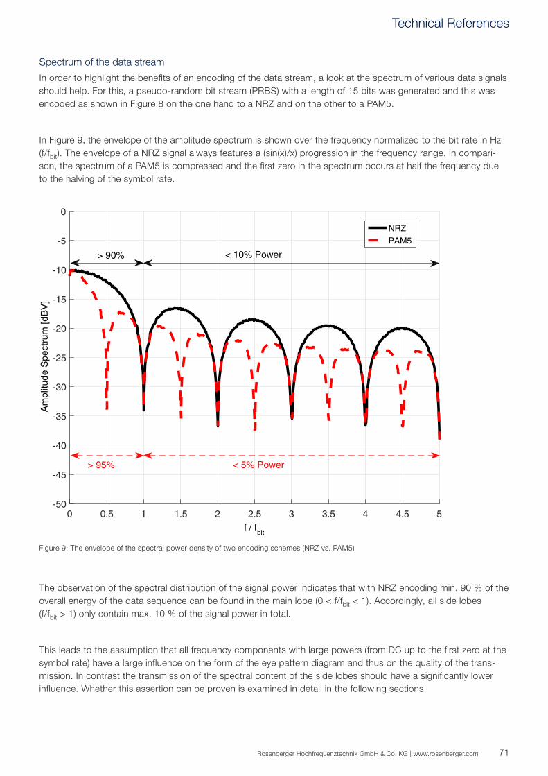
0 0.5 1 1.5 2 2.5 3 3.5 4 4.5 5f / f
bit
-50
-45
-40
-35
-30
-25
-20
-15
-10
-5
0
Am
plitu
de S
pect
rum
[dB
V]
NRZPAM5
> 90% < 10% Power
> 95% < 5% Power
71Rosenberger Hochfrequenztechnik GmbH & Co. KG | www.rosenberger.com
Spectrum of the data stream
In order to highlight the benefits of an encoding of the data stream, a look at the spectrum of various data signals should help. For this, a pseudo-random bit stream (PRBS) with a length of 15 bits was generated and this was encoded as shown in Figure 8 on the one hand to a NRZ and on the other to a PAM5.
In Figure 9, the envelope of the amplitude spectrum is shown over the frequency normalized to the bit rate in Hz (f/fbit). The envelope of a NRZ signal always features a (sin(x)/x) progression in the frequency range. In compari-son, the spectrum of a PAM5 is compressed and the first zero in the spectrum occurs at half the frequency due to the halving of the symbol rate.
The observation of the spectral distribution of the signal power indicates that with NRZ encoding min. 90 % of the overall energy of the data sequence can be found in the main lobe (0 < f/fbit < 1). Accordingly, all side lobes (f/fbit > 1) only contain max. 10 % of the signal power in total.
This leads to the assumption that all frequency components with large powers (from DC up to the first zero at the symbol rate) have a large influence on the form of the eye pattern diagram and thus on the quality of the trans-mission. In contrast the transmission of the spectral content of the side lobes should have a significantly lower influence. Whether this assertion can be proven is examined in detail in the following sections.
Figure 9: The envelope of the spectral power density of two encoding schemes (NRZ vs. PAM5)
Technical References
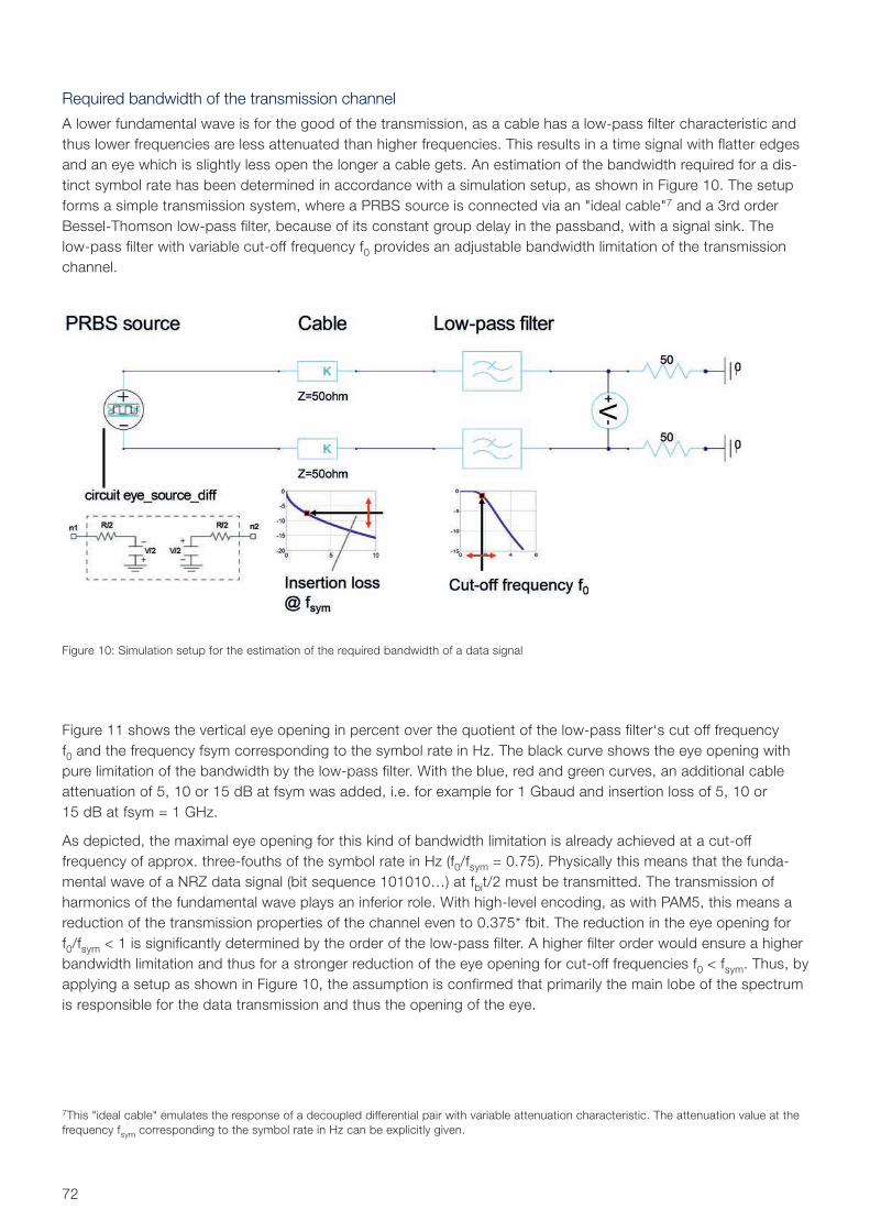
72
Required bandwidth of the transmission channel
A lower fundamental wave is for the good of the transmission, as a cable has a low-pass filter characteristic and thus lower frequencies are less attenuated than higher frequencies. This results in a time signal with flatter edges and an eye which is slightly less open the longer a cable gets. An estimation of the bandwidth required for a dis-tinct symbol rate has been determined in accordance with a simulation setup, as shown in Figure 10. The setup forms a simple transmission system, where a PRBS source is connected via an "ideal cable"7 and a 3rd order Bessel-Thomson low-pass filter, because of its constant group delay in the passband, with a signal sink. The low-pass filter with variable cut-off frequency f0 provides an adjustable bandwidth limitation of the transmission channel.
Figure 11 shows the vertical eye opening in percent over the quotient of the low-pass filter‘s cut off frequency f0 and the frequency fsym corresponding to the symbol rate in Hz. The black curve shows the eye opening with pure limitation of the bandwidth by the low-pass filter. With the blue, red and green curves, an additional cable attenuation of 5, 10 or 15 dB at fsym was added, i.e. for example for 1 Gbaud and insertion loss of 5, 10 or 15 dB at fsym = 1 GHz.
As depicted, the maximal eye opening for this kind of bandwidth limitation is already achieved at a cut-off frequency of approx. three-fouths of the symbol rate in Hz (f0/fsym = 0.75). Physically this means that the funda-mental wave of a NRZ data signal (bit sequence 101010…) at fbit/2 must be transmitted. The transmission of harmonics of the fundamental wave plays an inferior role. With high-level encoding, as with PAM5, this means a reduction of the transmission properties of the channel even to 0.375* fbit. The reduction in the eye opening for f0/fsym < 1 is significantly determined by the order of the low-pass filter. A higher filter order would ensure a higher bandwidth limitation and thus for a stronger reduction of the eye opening for cut-off frequencies f0 < fsym. Thus, by applying a setup as shown in Figure 10, the assumption is confirmed that primarily the main lobe of the spectrum is responsible for the data transmission and thus the opening of the eye.
Figure 10: Simulation setup for the estimation of the required bandwidth of a data signal
7This "ideal cable" emulates the response of a decoupled differential pair with variable attenuation characteristic. The attenuation value at the frequency fsym corresponding to the symbol rate in Hz can be explicitly given.
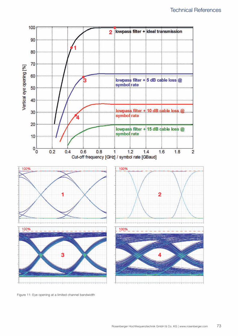
73Rosenberger Hochfrequenztechnik GmbH & Co. KG | www.rosenberger.com
Figure 11: Eye opening at a limited channel bandwidth
Technical References
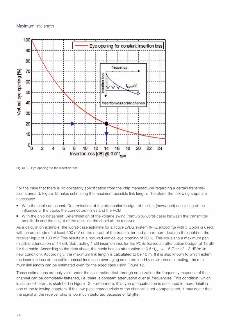
74
Maximum link length
For the case that there is no obligatory specification from the chip manufacturer regarding a certain transmis-sion standard, Figure 12 helps estimating the maximum possible link length. Therefore, the following steps are necessary:
With the cable datasheet: Determination of the attenuation budget of the link (new/aged) consisting of the influence of the cable, the connector/inlines and the PCB
With the chip datasheet: Determination of the voltage swing (max./typ./worst-case) between the transmitter amplitude and the height of the decision threshold at the receiver.
As a calculation example, the worst-case estimate for a fictive LVDS system (NRZ encoding) with 3 Gbit/s is used, with an amplitude of at least 500 mV on the output of the transmitter and a maximum decision threshold on the receiver input of 100 mV. This results in a required vertical eye opening of 20 %. This equals to a maximum per-missible attenuation of 14 dB. Subtracting 1 dB insertion loss for the PCBs leaves an attenuation budget of 13 dB for the cable. According to the data sheet, the cable has an attenuation at 0.5* fsym = 1.5 GHz of 1.3 dB/m (in new condition). Accordingly, the maximum link length is calculated to be 10 m. If it is also known to which extent the insertion loss of the cable material increases over aging as determined by environmental testing, the maxi-mum link length can be estimated even for the aged case using Figure 12.
These estimations are only valid under the assumption that through equalization the frequency response of the channel can be completely flattened, i.e. there is constant attenuation over all frequencies. This condition, which is state-of-the-art, is sketched in Figure 12. Furthermore, this type of equalization is described in more detail in one of the following chapters. If the low-pass characteristic of the channel is not compensated, it may occur that the signal at the receiver chip is too much distorted because of ISI jitter.
Figure 12: Eye opening via the insertion loss
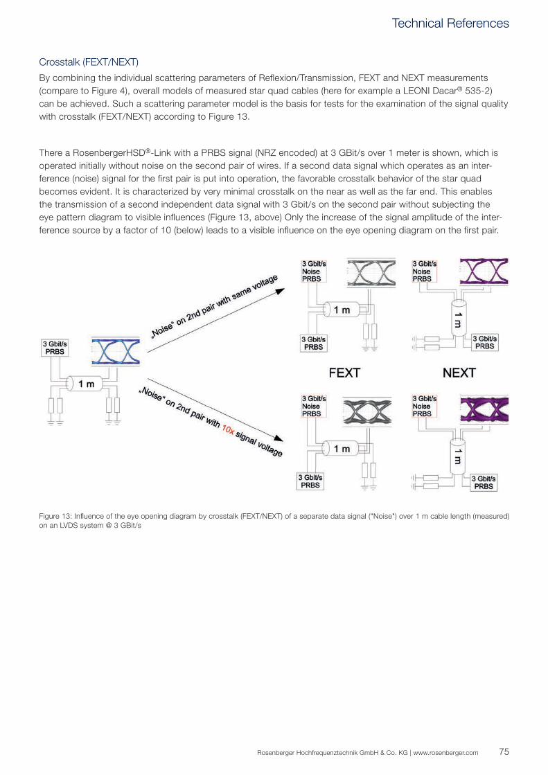
75Rosenberger Hochfrequenztechnik GmbH & Co. KG | www.rosenberger.com
Figure 13: Influence of the eye opening diagram by crosstalk (FEXT/NEXT) of a separate data signal ("Noise") over 1 m cable length (measured) on an LVDS system @ 3 GBit/s
Crosstalk (FEXT/NEXT)
By combining the individual scattering parameters of Reflexion/Transmission, FEXT and NEXT measurements (compare to Figure 4), overall models of measured star quad cables (here for example a LEONI Dacar® 535-2) can be achieved. Such a scattering parameter model is the basis for tests for the examination of the signal quality with crosstalk (FEXT/NEXT) according to Figure 13.
There a RosenbergerHSD®-Link with a PRBS signal (NRZ encoded) at 3 GBit/s over 1 meter is shown, which is operated initially without noise on the second pair of wires. If a second data signal which operates as an inter-ference (noise) signal for the first pair is put into operation, the favorable crosstalk behavior of the star quad becomes evident. It is characterized by very minimal crosstalk on the near as well as the far end. This enables the transmission of a second independent data signal with 3 Gbit/s on the second pair without subjecting the eye pattern diagram to visible influences (Figure 13, above) Only the increase of the signal amplitude of the inter-ference source by a factor of 10 (below) leads to a visible influence on the eye opening diagram on the first pair.
Technical References
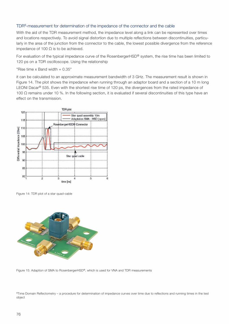
76
TDR8-measurement for determination of the impedance of the connector and the cable
With the aid of the TDR measurement method, the impedance level along a link can be represented over times and locations respectively. To avoid signal distortion due to multiple reflections between discontinuities, particu-larly in the area of the junction from the connector to the cable, the lowest possible divergence from the reference impedance of 100 Ω is to be achieved.
For evaluation of the typical impedance curve of the RosenbergerHSD® system, the rise time has been limited to 120 ps on a TDR oscilloscope. Using the relationship
"Rise time x Band width = 0.35"
it can be calculated to an approximate measurement bandwidth of 3 GHz. The measurement result is shown in Figure 14. The plot shows the impedance when running through an adaptor board and a section of a 10 m long LEONI Dacar® 535. Even with the shortest rise time of 120 ps, the divergences from the rated impedance of 100 Ω remains under 10 %. In the following section, it is evaluated if several discontinuities of this type have an effect on the transmission.
Figure 14: TDR plot of a star quad-cable
Figure 15: Adaption of SMA to RosenbergerHSD®, which is used for VNA and TDR measurements
8Time Domain Reflectometry – a procedure for determination of impedance curves over time due to reflections and running times in the test object
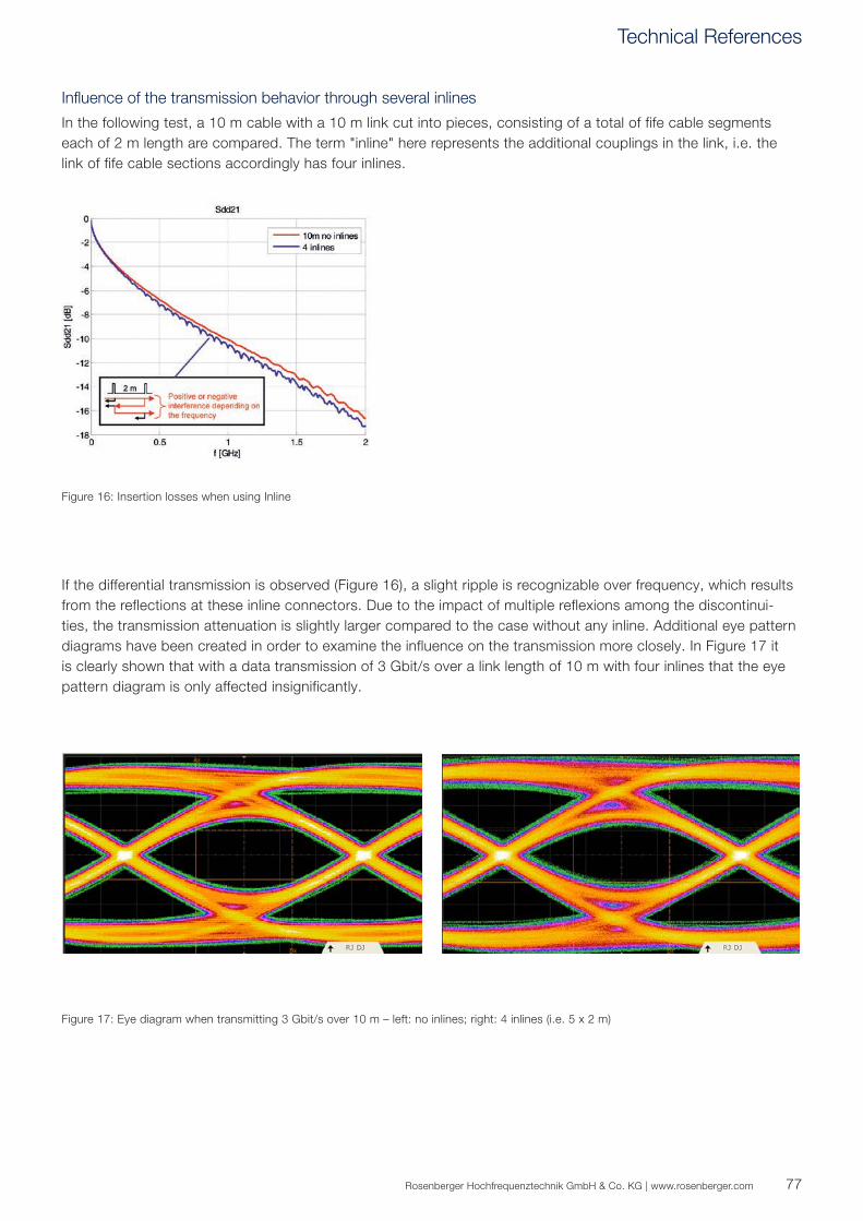
77Rosenberger Hochfrequenztechnik GmbH & Co. KG | www.rosenberger.com
Figure 17: Eye diagram when transmitting 3 Gbit/s over 10 m – left: no inlines; right: 4 inlines (i.e. 5 x 2 m)
Figure 16: Insertion losses when using Inline
Influence of the transmission behavior through several inlines
In the following test, a 10 m cable with a 10 m link cut into pieces, consisting of a total of fife cable segments each of 2 m length are compared. The term "inline" here represents the additional couplings in the link, i.e. the link of fife cable sections accordingly has four inlines.
If the differential transmission is observed (Figure 16), a slight ripple is recognizable over frequency, which results from the reflections at these inline connectors. Due to the impact of multiple reflexions among the discontinui-ties, the transmission attenuation is slightly larger compared to the case without any inline. Additional eye pattern diagrams have been created in order to examine the influence on the transmission more closely. In Figure 17 it is clearly shown that with a data transmission of 3 Gbit/s over a link length of 10 m with four inlines that the eye pattern diagram is only affected insignificantly.
Technical References
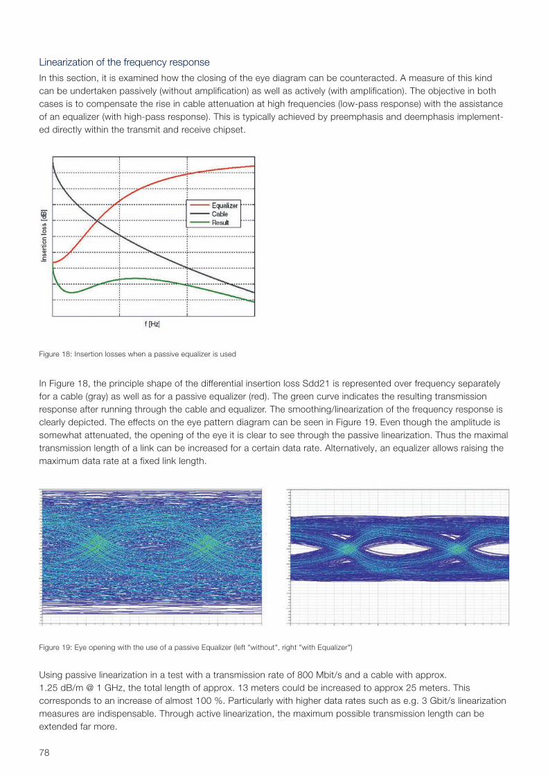
78
Linearization of the frequency response
In this section, it is examined how the closing of the eye diagram can be counteracted. A measure of this kind can be undertaken passively (without amplification) as well as actively (with amplification). The objective in both cases is to compensate the rise in cable attenuation at high frequencies (low-pass response) with the assistance of an equalizer (with high-pass response). This is typically achieved by preemphasis and deemphasis implement-ed directly within the transmit and receive chipset.
Figure 18: Insertion losses when a passive equalizer is used
Figure 19: Eye opening with the use of a passive Equalizer (left "without", right "with Equalizer")
In Figure 18, the principle shape of the differential insertion loss Sdd21 is represented over frequency separately for a cable (gray) as well as for a passive equalizer (red). The green curve indicates the resulting transmission response after running through the cable and equalizer. The smoothing/linearization of the frequency response is clearly depicted. The effects on the eye pattern diagram can be seen in Figure 19. Even though the amplitude is somewhat attenuated, the opening of the eye it is clear to see through the passive linearization. Thus the maximal transmission length of a link can be increased for a certain data rate. Alternatively, an equalizer allows raising the maximum data rate at a fixed link length.
Using passive linearization in a test with a transmission rate of 800 Mbit/s and a cable with approx. 1.25 dB/m @ 1 GHz, the total length of approx. 13 meters could be increased to approx 25 meters. This corresponds to an increase of almost 100 %. Particularly with higher data rates such as e.g. 3 Gbit/s lineari zation measures are indispensable. Through active linearization, the maximum possible transmission length can be extended far more.
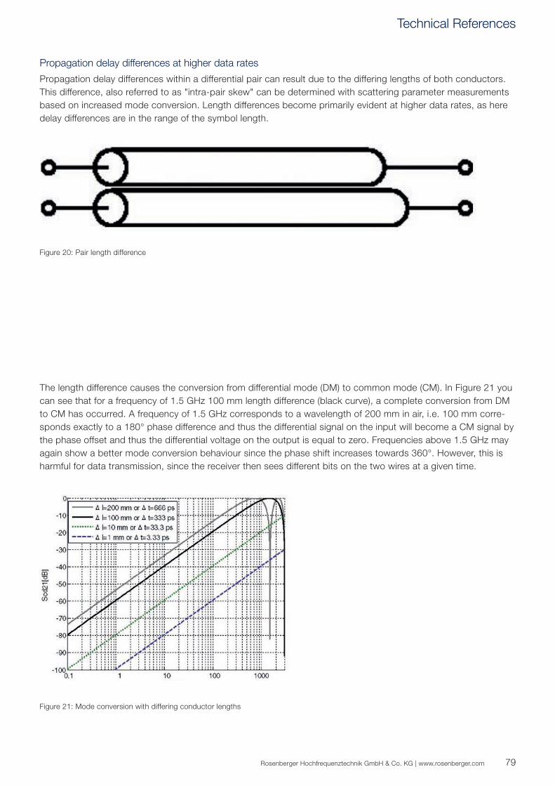
79Rosenberger Hochfrequenztechnik GmbH & Co. KG | www.rosenberger.com
Figure 21: Mode conversion with differing conductor lengths
Figure 20: Pair length difference
Propagation delay differences at higher data rates
Propagation delay differences within a differential pair can result due to the differing lengths of both conductors. This difference, also referred to as "intra-pair skew" can be determined with scattering parameter measurements based on increased mode conversion. Length differences become primarily evident at higher data rates, as here delay differences are in the range of the symbol length.
The length difference causes the conversion from differential mode (DM) to common mode (CM). In Figure 21 you can see that for a frequency of 1.5 GHz 100 mm length difference (black curve), a complete conversion from DM to CM has occurred. A frequency of 1.5 GHz corresponds to a wavelength of 200 mm in air, i.e. 100 mm corre-sponds exactly to a 180° phase difference and thus the differential signal on the input will become a CM signal by the phase offset and thus the differential voltage on the output is equal to zero. Frequencies above 1.5 GHz may again show a better mode conversion behaviour since the phase shift increases towards 360°. However, this is harmful for data transmission, since the receiver then sees different bits on the two wires at a given time.
Technical References
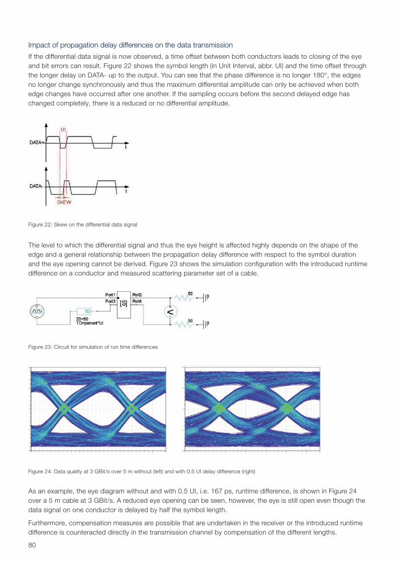
80
Impact of propagation delay differences on the data transmission
If the differential data signal is now observed, a time offset between both conductors leads to closing of the eye and bit errors can result. Figure 22 shows the symbol length (in Unit Interval, abbr. UI) and the time offset through the longer delay on DATA- up to the output. You can see that the phase difference is no longer 180°, the edges no longer change synchronously and thus the maximum differential amplitude can only be achieved when both edge changes have occurred after one another. If the sampling occurs before the second delayed edge has changed completely, there is a reduced or no differential amplitude.
Figure 22: Skew on the differential data signal
Figure 23: Circuit for simulation of run time differences
Figure 24: Data quality at 3 GBit/s over 5 m without (left) and with 0.5 UI delay difference (right)
The level to which the differential signal and thus the eye height is affected highly depends on the shape of the edge and a general relationship between the propagation delay difference with respect to the symbol duration and the eye opening cannot be derived. Figure 23 shows the simulation configuration with the introduced runtime difference on a conductor and measured scattering parameter set of a cable.
As an example, the eye diagram without and with 0.5 UI, i.e. 167 ps, runtime difference, is shown in Figure 24 over a 5 m cable at 3 GBit/s. A reduced eye opening can be seen, however, the eye is still open even though the data signal on one conductor is delayed by half the symbol length.
Furthermore, compensation measures are possible that are undertaken in the receiver or the introduced runtime difference is counteracted directly in the transmission channel by compensation of the different lengths.
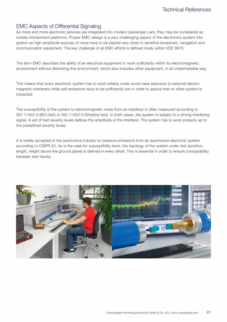
81Rosenberger Hochfrequenztechnik GmbH & Co. KG | www.rosenberger.com
EMC Aspects of Differential SignalingAs more and more electronic services are integrated into modern passenger cars, they may be considered as mobile infotainment platforms. Proper EMC-design is a very challenging aspect of the electronics system inte-gration as high amplitude sources of noise have to be placed very close to sensitive broadcast, navigation and communication equipment. The key challenge of all EMC efforts is defined nicely within VDE 0870:
The term EMC describes the ability of an electrical equipment to work sufficiently within its electromagnetic environment without disturbing this environment, which also includes other equipment, in an impermissible way.
This means that every electronic system has to work reliably under worst case exposure to external electro-magnetic interferers while self-emissions have to be sufficiently low in order to assure that no other system is impacted.
The susceptibility of the system to electromagnetic noise from an interferer is often measured according to ISO 11452-4 (BCI-test) or ISO 11452-5 (Stripline test). In both cases, the system is subject to a strong interfering signal. A set of test severity levels defines the amplitude of the interferer. The system has to work properly up to the predefined severity levels.
It is widely accepted in the automotive industry to measure emissions from an auto motive electronic system according to CISPR 25. As is the case for susceptibility tests, the topology of the system under test (position, length, height above the ground plane) is defined in every detail. This is essential in order to ensure comparability between test results.
Technical References
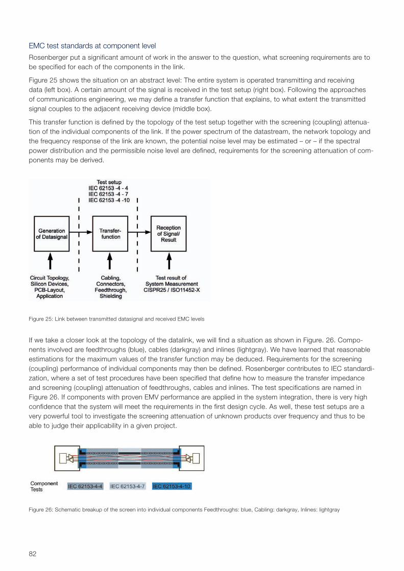
82
EMC test standards at component level
Rosenberger put a significant amount of work in the answer to the question, what screening requirements are to be specified for each of the components in the link.
Figure 25 shows the situation on an abstract level: The entire system is operated transmitting and receiving data (left box). A certain amount of the signal is received in the test setup (right box). Following the approaches of communications engineering, we may define a transfer function that explains, to what extent the transmitted signal couples to the adjacent receiving device (middle box).
This transfer function is defined by the topology of the test setup together with the screening (coupling) attenua-tion of the individual components of the link. If the power spectrum of the datastream, the network topology and the frequency response of the link are known, the potential noise level may be estimated – or – if the spectral power distribution and the permissible noise level are defined, requirements for the screening attenuation of com-ponents may be derived.
Figure 25: Link between transmitted datasignal and received EMC levels
Figure 26: Schematic breakup of the screen into individual components Feedthroughs: blue, Cabling: darkgray, Inlines: lightgray
If we take a closer look at the topology of the datalink, we will find a situation as shown in Figure. 26. Compo-nents involved are feedthroughs (blue), cables (darkgray) and inlines (lightgray). We have learned that reasonable estimations for the maximum values of the transfer function may be deduced. Requirements for the screening (coupling) performance of individual components may then be defined. Rosenberger contributes to IEC standardi-zation, where a set of test procedures have been specified that define how to measure the transfer impedance and screening (coupling) attenuation of feedthroughs, cables and inlines. The test specifications are named in Figure 26. If components with proven EMV performance are applied in the system integration, there is very high confidence that the system will meet the requirements in the first design cycle. As well, these test setups are a very powerful tool to investigate the screening attenuation of unknown products over frequency and thus to be able to judge their applicability in a given project.
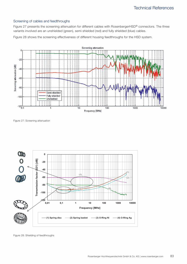
-120
-100
-80
-60
-40
-20
0
Tran
smis
sion
fact
or (S
21) [
dB]
0,01 0,1 1 10 100 1000 10000
Frequency [MHz]
(1) Spring disc (2) Spring basket (3) O-Ring Ni (4) O-Ring Ag
(1)
(2)(3)
(4)
83Rosenberger Hochfrequenztechnik GmbH & Co. KG | www.rosenberger.com
Figure 27: Screening attenuation
Figure 28: Shielding of feedthroughs
Screening of cables and feedthroughs
Figure 27 presents the screening attenuation for different cables with RosenbergerHSD® connectors. The three variants involved are an unshielded (green), semi shielded (red) and fully shielded (blue) cables.
Figure 28 shows the screening effectiveness of different housing feedthroughs for the HSD system.
Technical References

84
Glossary
Common mode: Describes the part of two signals that has same phase and amplitude [(U1+U2)/2].
Differential mode: Describes the difference of two signals [U1-U2]. For maximum differential signal the two signals have to be shifted by 180°.
FEXT: Far End Crosstalk, describes the part of an input signal that couples into an adjacent wire or diff. pair at the far end, i.e. from one end of the cable to the other.
NEXT: Near End Crosstalk, describes the part of an input signal that couples into an adjacent wire or diff. pair at the near end, i.e. at the same end of the cable.
TDR: Time Domain Reflectometry, a time domain measurement technique that uses a voltage pulse in order to show impedance over time or spatially resolved.
85Rosenberger Hochfrequenztechnik GmbH & Co. KG | www.rosenberger.com
Glossary
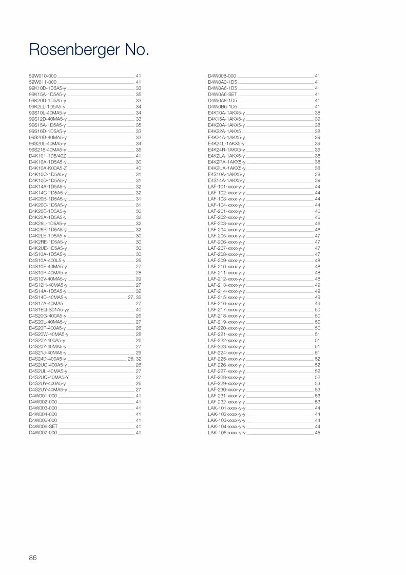
86
Rosenberger No.59W010-000 4159W011-000 4199K10D-1D5A5-y 3399K15A-1D5A5-y 3599K20D-1D5A5-y 3399K2LL-1D5A5-y 3499S10L-40MA5-y 3499S12D-40MA5-y 3399S15A-1D5A5-y 3599S16D-1D5A5-y 3399S20D-40MA5-y 3399S20L-40MA5-y 3499S218-40MA5-y 35D4K101-1D5/40Z 41D4K10A-1D5A5-y 30D4K10A-K00A5-Z 40D4K10C-1D5A5-y 31D4K10D-1D5A5-y 31D4K14A-1D5A5-y 32D4K14C-1D5A5-y 32D4K20B-1D5A5-y 31D4K20C-1D5A5-y 31D4K20E-1D5A5-y 30D4K25A-1D5A5-y 32D4K25L-1D5A5-y 32D4K25R-1D5A5-y 32D4K2LE-1D5A5-y 30D4K2RE-1D5A5-y 30D4K2UE-1D5A5-y 30D4S10A-1D5A5-y 30D4S10A-400L5-y 26D4S10E-40MA5-y 27D4S10P-40MA5-y 28D4S10V-40MA5-y 29D4S12H-40MA5-y 27D4S14A-1D5A5-y 32D4S14D-40MA5-y 27, 32D4S17A-40MA5 27D4S1EQ-S01A5-yy 40D4S20G-400A5-y 26D4S20L-40MA5-y 27D4S20P-400A5-y 26D4S20W-40MA5-y 28D4S20Y-400A5-y 26D4S20Y-40MA5-y 27D4S21J-40MA5-y 29D4S24D-400A5-y 26, 32D4S2UG-400A5-y 26D4S2UL-40MA5-y 27D4S2UQ-40MA5-Y 27D4S2UY-400A5-y 26D4S2UY-40MA5-y 27D4W001-000 41D4W002-000 41D4W003-000 41D4W004-000 41D4W006-000 41D4W006-SET 41D4W007-000 41
D4W008-000 41D4W0A3-1D5 41D4W0A6-1D5 41D4W0A6-SET 41D4W0A8-1D5 41D4W0B6-1D5 41E4K10A-1AKX5-y 38E4K15A-1AKX5-y 39E4K20A-1AKX5-y 38E4K22A-1AKX5 38E4K24A-1AKX5-y 39E4K24L-1AKX5-y 39E4K24R-1AKX5-y 39E4K2LA-1AKX5-y 38E4K2RA-1AKX5-y 38E4K2UA-1AKX5-y 38E4S10A-1AKX5-y 38E4S14A-1AKX5-y 39LAF-101-xxxx-y-y 44LAF-102-xxxx-y-y 44LAF-103-xxxx-y-y 44LAF-104-xxxx-y-y 44LAF-201-xxxx-y-y 46LAF-202-xxxx-y-y 46LAF-203-xxxx-y-y 46LAF-204-xxxx-y-y 46LAF-205-xxxx-y-y 47LAF-206-xxxx-y-y 47LAF-207-xxxx-y-y 47LAF-208-xxxx-y-y 47LAF-209-xxxx-y-y 48LAF-210-xxxx-y-y 48LAF-211-xxxx-y-y 48LAF-212-xxxx-y-y 48LAF-213-xxxx-y-y 49LAF-214-xxxx-y-y 49LAF-215-xxxx-y-y 49LAF-216-xxxx-y-y 49LAF-217-xxxx-y-y 50LAF-218-xxxx-y-y 50LAF-219-xxxx-y-y 50LAF-220-xxxx-y-y 50LAF-221-xxxx-y-y 51LAF-222-xxxx-y-y 51LAF-223-xxxx-y-y 51LAF-224-xxxx-y-y 51LAF-225-xxxx-y-y 52LAF-226-xxxx-y-y 52LAF-227-xxxx-y-y 52LAF-228-xxxx-y-y 52LAF-229-xxxx-y-y 53LAF-230-xxxx-y-y 53LAF-231-xxxx-y-y 53LAF-232-xxxx-y-y 53LAK-101-xxxx-y-y 44LAK-102-xxxx-y-y 44LAK-103-xxxx-y-y 44LAK-104-xxxx-y-y 44LAK-105-xxxx-y-y 45
Rosenberger Hochfrequenztechnik GmbH & Co. KG | www.rosenberger.com
Status June 2017 – Technical modifications and errors excepted. Similar images.
87
LAK-106-xxxx-y-y 45LAK-107-xxxx-y-y 45LAK-108-xxxx-y-y 45LAK-201-xxxx-y-y 46LAK-202-xxxx-y-y 46LAK-203-xxxx-y-y 46LAK-204-xxxx-y-y 46LAK-205-xxxx-y-y 47LAK-206-xxxx-y-y 47LAK-207-xxxx-y-y 47LAK-208-xxxx-y-y 47LAK-209-xxxx-y-y 48LAK-210-xxxx-y-y 48LAK-211-xxxx-y-y 48LAK-212-xxxx-y-y 48LAK-213-xxxx-y-y 49LAK-214-xxxx-y-y 49LAK-215-xxxx-y-y 49LAK-216-xxxx-y-y 49LAK-217-xxxx-y-y 50LAK-218-xxxx-y-y 50LAK-219-xxxx-y-y 50LAK-220-xxxx-y-y 50LAK-221-xxxx-y-y 51LAK-222-xxxx-y-y 51LAK-223-xxxx-y-y 51LAK-224-xxxx-y-y 51LAK-225-xxxx-y-y 52LAK-226-xxxx-y-y 52LAK-227-xxxx-y-y 52LAK-228-xxxx-y-y 52LAK-229-xxxx-y-y 53LAK-230-xxxx-y-y 53LAK-231-xxxx-y-y 53LAK-232-xxxx-y-y 53LD5-101-xxxx-y-y 44LD5-102-xxxx-y-y 44LD5-103-xxxx-y-y 44LD5-104-xxxx-y-y 44LD5-105-xxxx-y-y 45LD5-106-xxxx-y-y 45LD5-107-xxxx-y-y 45LD5-108-xxxx-y-y 45LD5-201-xxxx-y-y 46LD5-202-xxxx-y-y 46LD5-203-xxxx-y-y 46LD5-204-xxxx-y-y 46LD5-205-xxxx-y-y 47LD5-206-xxxx-y-y 47LD5-207-xxxx-y-y 47LD5-208-xxxx-y-y 47LD5-209-xxxx-y-y 48LD5-210-xxxx-y-y 48LD5-211-xxxx-y-y 48LD5-212-xxxx-y-y 48LD5-213-xxxx-y-y 49LD5-214-xxxx-y-y 49LD5-215-xxxx-y-y 49LD5-216-xxxx-y-y 49
LD5-217-xxxx-y-y 50LD5-218-xxxx-y-y 50LD5-219-xxxx-y-y 50LD5-220-xxxx-y-y 50LD5-221-xxxx-y-y 51LD5-222-xxxx-y-y 51LD5-223-xxxx-y-y 51LD5-224-xxxx-y-y 51LD5-225-xxxx-y-y 52LD5-226-xxxx-y-y 52LD5-227-xxxx-y-y 52LD5-228-xxxx-y-y 52LD5-229-xxxx-y-y 53LD5-230-xxxx-y-y 53LD5-231-xxxx-y-y 53LD5-232-xxxx-y-y 53PCB-L1501-SB 41
Index
Rosenberger Hochfrequenztechnik GmbH & Co. KGHauptstraße 1 | 83413 FridolfingP.O. Box 1260 | 84526 Tittmoning GermanyPhone +49 8684 [email protected] by ISO/TS 16949 · DIN EN 9100 · ISO 9001 · ISO 14001
Order No.pA 170061 · Info205HSDCat2000/2017
Rosenberger® and RosenbergerHSD® are registered trademarks of Rosenberger Hochfrequenztechnik GmbH & Co. KG.All rights reserved.
© Rosenberger 2017
Website For more information refer to our website: www.rosenberger.com/hsd