Embed Size (px)
Citation preview
High-speed optical studies of the long sparks in very transient stages
Yuri V. Shcherbakova1, Vitali B. Lebedevb, Vladimir A. Rakovc, Grigori G. Feldmanb, Boris N. Gorinb, Vladimir S. Syssoeva and Maksim A. Karpovb
a High Voltage Research Center of the All-Russian Electrotechnical Institute, Istra-2, Moscow Reg., Russia
b BIFO Company, Ozernaya st. 46, Moscow, Russia c Department of Electrical and Computer Engineering, University of Florida, Gainesville, USA
ABSTRACT
High-speed optical studies of different stages of the long sparks have been carried out at the High Voltage Research Center (HVRC), Istra, Russia, using up to three devices operated synchronously: two novel universal streak and framing cameras K004M and K008 developed by the BIFO Company and an analog image converter streak camera of FER14-type instrumented with a CCD readout system of SU04-type. Special attention was paid to the improved spatiotemporal resolution when recording the pictures of large sizes. The measurements were conducted in rod-to-plane gap of 5.5÷6 m in length under both polarities HV pulses of 2÷3 MV in altitude with waveform of 20/7500 and 100/7500 µs. Under negative polarity, an additional thin metallic rod about of 1 m in length was placed on the grounded plane to provide an origin of the positive upward leader and its reliable observation. The velocity of approaching the downward negative streamer-leader system and upward positive leader toward each other near the junction point has been found to be around 5÷10 m/µs. Some supporting exemplary pictures have been recorded to additionally clarify the phenomenology of the stepped or/and attempted leaders, which can be useful for analysis of long spark and lightning treeing and development.
Keywords: Long spark, streamer-leader system, downward and upward leaders, return stroke, streak and frame image, image converter camera
1. INTRODUCTION Upward leader and return stroke of the long sparks and of the lightning are of most key phenomena for the lightning theory and lightning protection. In this work, we have tried to receive good streak and frame images of the long sparks during pre-final and final stages, which could show distinct structure as well as be suitable for direct estimation of the velocity of the phenomena mentioned. The way to make this possible was in using up to three novel universal streak and framing cameras operated synchronously in different modes. Measurements were conducted at the conditions (apertures, spatial and time resolution, illumination responsivity etc) like as much as possible to those expected in actual triggered-lightning experiments at Camp Blanding.
2. EXPERIMENTAL SETUP 2.1 Equipment arrangement and gap conditions
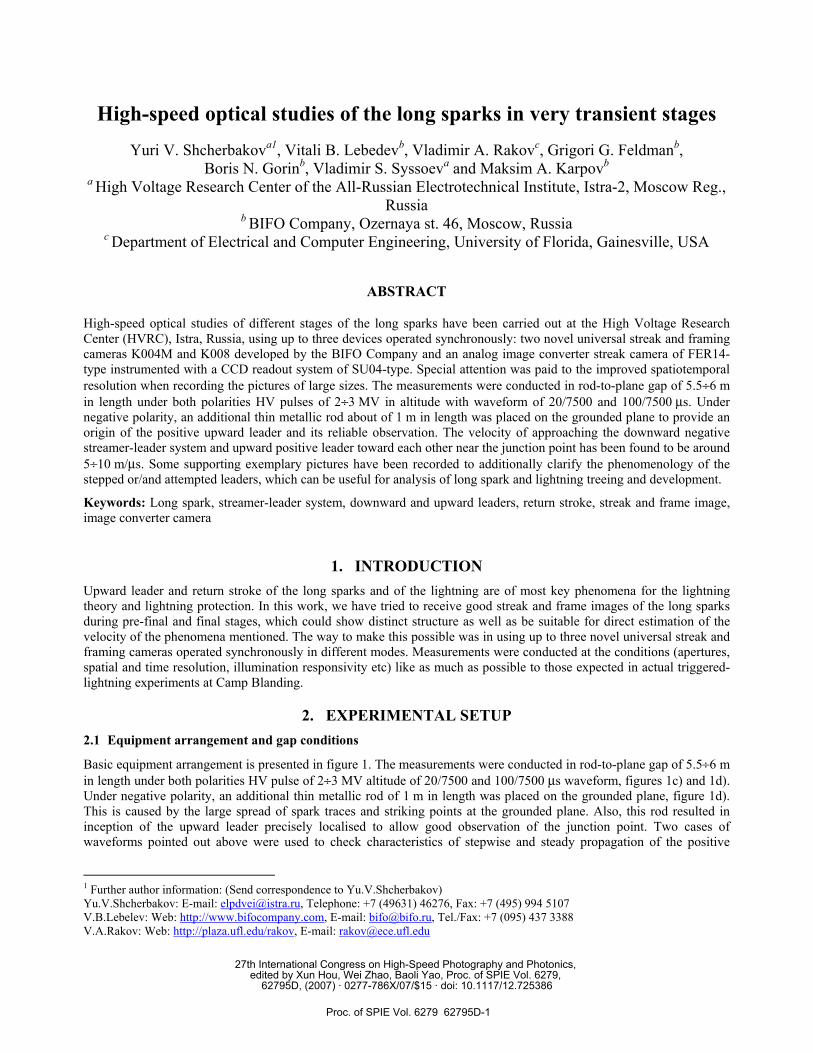
Basic equipment arrangement is presented in figure 1. The measurements were conducted in rod-to-plane gap of 5.5÷6 m in length under both polarities HV pulse of 2÷3 MV altitude of 20/7500 and 100/7500 µs waveform, figures 1c) and 1d). Under negative polarity, an additional thin metallic rod of 1 m in length was placed on the grounded plane, figure 1d). This is caused by the large spread of spark traces and striking points at the grounded plane. Also, this rod resulted in inception of the upward leader precisely localised to allow good observation of the junction point. Two cases of waveforms pointed out above were used to check characteristics of stepwise and steady propagation of the positive
1 Further author information: (Send correspondence to Yu.V.Shcherbakov) Yu.V.Shcherbakov: E-mail: [email protected], Telephone: +7 (49631) 46276, Fax: +7 (495) 994 5107 V.B.Lebelev: Web: http://www.bifocompany.com, E-mail: [email protected], Tel./Fax: +7 (095) 437 3388 V.A.Rakov: Web: http://plaza.ufl.edu/rakov, E-mail: [email protected]
27th International Congress on High-Speed Photography and Photonics, edited by Xun Hou, Wei Zhao, Baoli Yao, Proc. of SPIE Vol. 6279,
62795D, (2007) · 0277-786X/07/$15 · doi: 10.1117/12.725386
Proc. of SPIE Vol. 6279 62795D-1
streamer-leader system, consequently. The shorter front waveform provided the brighter and faster steps (re-strikes) of the streamer-leader system. Such variety of the luminosity dynamic ranges was very useful for tuning the reduced level of the image intensification of the ICC immediately after too bright re-strikes or in the final stage.
2.2 Cameras performance and optics
Detailed description of the cameras and other supporting devices applied here, figure 2, can be found at the BIFO’s web-site [1] and partially in the paper containing the initial results [2]. Main characteristics of the universal streak and multiframing ICC K004M are as follows:
43 m
45 m 70 m
a)
b)
90 m
10 m 10 m
10 m10 m
+
2 m 2 m
c) −
2 m2 m
d)
e)
Fig. 1. Basic experimental set-up: a) and b) general frontal and top views, c), d) and e) peculiar enlarged parts: 1 HV generator, 2 mast, 3 conductor, 4 insulating rope 5 metallic rod, 6 grounded plane, 7 spark discharge trace, 8 remote measuring and control room, 9 ICC location (the cameras from left top to right bottom being K008, FER14 and K004M, consequently), 10 additional metallic rod on the plane, 11 control unit, 12 PCs operated with the cameras. Figures c) and d) correspond to positive and negative polarities of the HV generator.
Proc. of SPIE Vol. 6279 62795D-2
K004M PS
K008
1) spectral range of the camera, 250÷800 nm; 2) working area of the photocathode (PhC), 8×8 mm2; 3) spatial resolution at the PhC, 10 lp/mm; 4) the MCP-based image intensifier (MCP-II) containing two MCP in series face to face; 5) working area of image converter tube (ICT) at the output luminescent screen (OLS) for streak mode, 35×16 mm2; 6) same for the framing mode, 28×28 mm2; 7) total (effective) spatial resolution of the device at the OLS, not worse than 7 lp/mm; 8) number of pixels of the CCD readout system, 640×480; 9) total gain factor of light conversion, from 0 to 2⋅106 W/W; 10) independent set up of exposure and interframe time in multiframing recording mode ranged from submicro- to
milliseconds; possible number of the frames being 1, 2, 4, 6 or 9; 11) sweep duration / resolution in streak mode ranged from 350/3 ns to 10/0.07 ms; 12) frame duration in single-frame mode ranged from 0.35 to 104 µs; 13) same in multi-frame mode ranged from 0.1 to 10 µs; 14) dead-time at the fast sweep durations and short exposure times is of about 0.2 µs; 15) available automatic adjustment of the reduced level of the image intensification.
Two additional cameras K008 and FER14 were being used in combination with the camera K004M in order to extend experimental capabilities as well as to compare and verify the pictures recorded. Super small streak and single frame image converter camera K008 to have an advanced performance on spatial resolution was being used to record exemplary pictures when the total responsivity was adequate. The analog image converter streak camera FER14 equipped with a single MCP-based image intensifier and instrumented with a CCD readout system SU04-type was being used mainly for recording the spark development from the origin to the final stage. Main technical characteristics of both cameras are given below; with a modified model FER14M presented instead of the FER14 camera itself. Each technical parameter is enumerated as for the K004M camera, the absentee ones omitted.
Main technical parameters of the K008 camera: 1) 400÷800 nm; 2) 15×20 mm2; 3) 12 lp/mm; 4) one MCP; 5) 20×12 mm2; 6) 15×20 mm2; 8) 640×480; 9) from 0 to 104 W/W; 14) 0.2 µs; 15) not available.
Main technical parameters of the FER14M camera: 1) 400÷800 nm; 2) 15×20 mm2; 3) 15 lp/mm; 4) two MCPs; 5) 35×16 mm2; 8) 1388×1024; 9) from 0 to 106 W/W; 15) available.
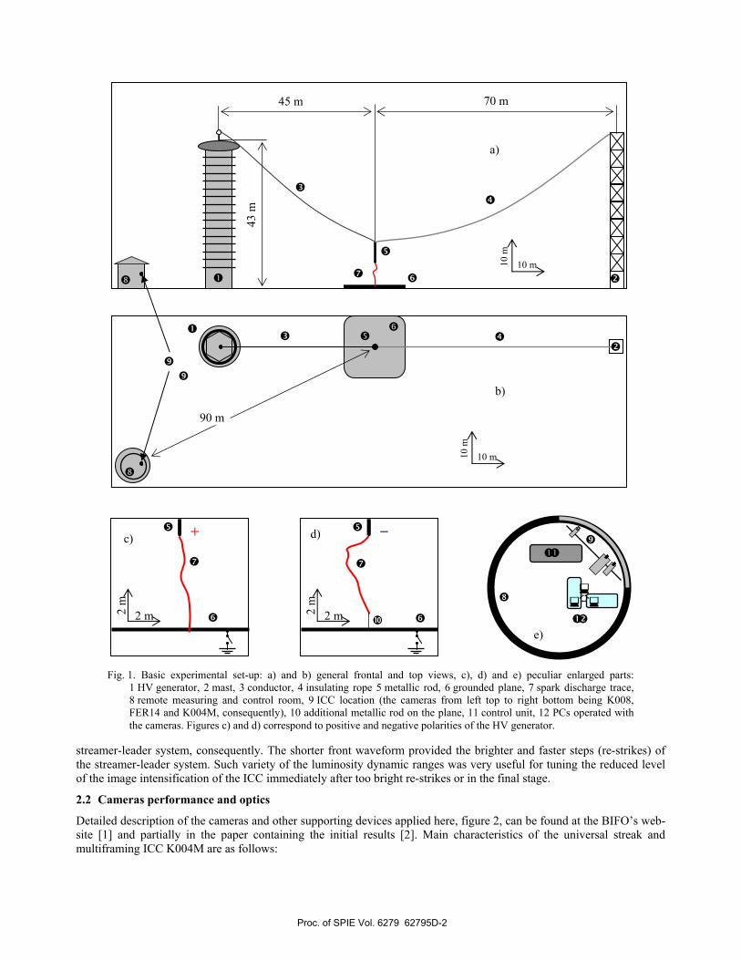
Design and appearance of the devices are presented in figure 1f).
Fig. 1f). Design and appearance of the image converter cameras K004M and K008 and of the photosensor (PS).
The pictures presented in the given paper have been obtained at the following combinations of the cameras and of the interchangeable objectives:
• K008 plus “Tair 33”, f=300 mm, aperture ratio ar = 1/2.8; • FER14 plus “Yupiter-9”, f=85 mm, ar = 1/2; • K004M plus:
Proc. of SPIE Vol. 6279 62795D-3
o transfocator “Granit-11”, f=80÷200 mm, used mainly at 150 mm, ar = 1/4.5, o UV objective, f=50 mm, ar = 1/3.5, spectral range from 250 to 450 nm.
3. EXPERIMENTAL RESULTS 3.1 Triggering and synchronization
The cameras were triggered with common or/and separate PMT-based photodetector receiving the light from the different spatial domains of the spark, providing thereby the spatial and time selection. In order to record different discharge stages of the spark development in various experimental conditions, the triggering level was accommodated with help of low- or high-sensitive inputs as well as with additional grey or colour filters. Binocular external photosensor (PS), figure 1f), combines two optical channels: 1) the triggering unit and 2) the unit providing the reference signal for automatic adjustment of the reduced level of the image intensification. If necessary, the discharge was being checked visually. The studies were mainly carried out in the night time.
With this method of triggering, in principle, one can provide synchronization and time localization of the observed stage with accuracy not worse than 0.2÷0.3 µs when recording the pictures around the final stage and near the primary flash. This is possible even for case of very large stochastic spread of the long spark development with time from pulse to pulse. Also, quite good time localization can be achieved during next re-strike at mid-gap distance because of burst increase of the light emission from spark. Just this fact allows good registration of the frame photograph of the re-strike recorded with short time of exposure.
3.2 Frame photographs of final and pre-final stages of the negative spark
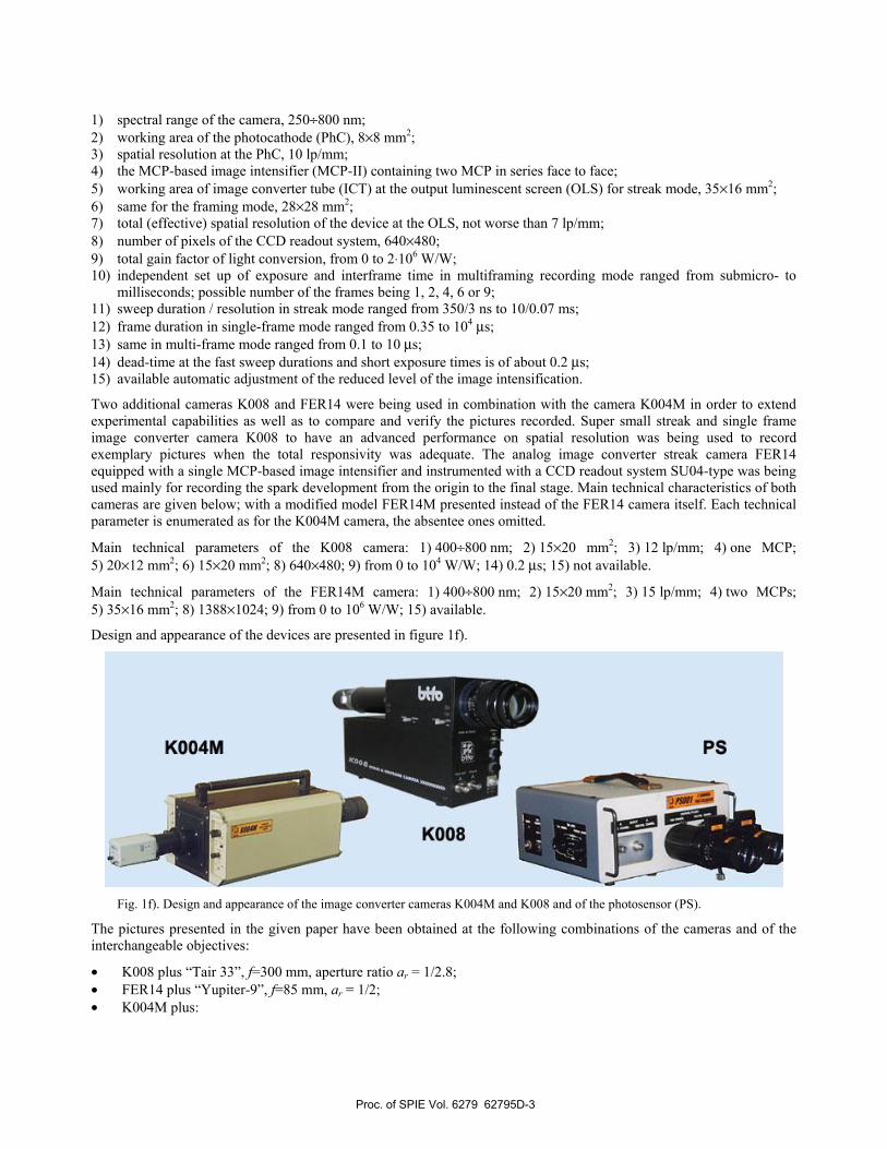
First, frame photographs of the final and post-final stages of negative spark, figure 2, have been received in 9-framing mode of the K004M camera; the negative potential rod being at the top. The figure illustrates the samples with the best quality of triggering and synchronisation that have been achieved for three channel registration together with other two cameras.
Exposure time for each frame was taken to be 0.1 µs; the first seven interframe times done to be 0.5 µs and last interframe time between the 8th and 9th frames done to be much larger than previous ones i.e. 25 µs. Time sequence of the frame exposure separated by the interframe times is thus as follows: (0.10.5)-(0.10.5)-(0.10.5)-(0.10.5)-(0.10.5)-(0.10.5)-(0.10.5)-(0.125)-0.1 µs. The dead triggering time is about of 0.2 µs. The frame sequence is shown in the appliqué placed between figures 2a) and 2b).
As well seen from figure 2b), the first four frames correspond to the pre-final stages yet without bridging over whole the gap. In the 4th frame, the negative downward streamer-leader system has arrived almost at the junction point located at least at distance about 1÷1.5 m from the grounded plane. In the 5th frame, there exists already full bridging with bright
Fig. 2. Pre-final, final and post-final stages of the spark discharge in negative rod (at the top) − to − plane gap of 5.5 m in length. Image converter camera K004M in 9-framing mode of registration.
Frame sequence 1 4 7 a) 2 5 8 b)
3 6 9
Proc. of SPIE Vol. 6279 62795D-4
spark channel. It can be concluded that space of time between the end of 4th frame and a point of starting the final stage is about 0.3÷0.5 µs. The figure 2b) helps to correctly understand instant of time in the 1st frame of figure 2a) related to another like spark discharge. First, evolution of the sparks around the junction point is very fast. Second, the transition from the moderate to the very strong brightness of the spark image occurs during only one frame. Third, as a rule, only two frames maintain such a very strong brightness, which diminishes essentially since beginning from third subsequent frame.
It can be then supposed that two most bright pictures pertain to the return stroke with duration around 0.7÷1.2 µs, the preceding picture does to pre-final stage, and the following ones do to final stage and spark decay. The 9th frame images pure static trace of the spark channel. After this consideration, we can state that just 1st frame in figure 2a) should correspond to the 5th frame in figure 2b) to pertain to the beginning of the return stroke.
Then, the picture in figure 2a) should be most appropriate in order to record a uniframe picture with high spatial and time resolution using the camera K008 to be operated synchronously with the K004M camera. This is because of the fact that the dead triggering time of the K008 camera is actually of about 0.2÷0.3 µs, i.e. almost the same as that of the K004M camera. The time of exposure of the K008 camera can be then reduced down to 0.1÷0.2 µs. So, the picture in figure 3a) obtained simultaneously with the K008 camera pertains to the same discharge as in figure 2a).
The best accuracy of triggering-synchronisation in this stage that can be practically achieved is not worse than 0.2÷0.3 µs. Since luminosity of the long spark and lightning is very different from flash to flash, not all discharges can be recorded at such good accuracy of synchronisation. Recording of many flashes may start as earlier as later at the given pre-set level of triggering by own light of the lightning. Probability of such a registration may be about 30 % (or maybe less) to allow good observation of dart leader with other details near the earth surface around the junction point in space and time. In other stages of the triggered lightning process, the claims to triggering-synchronisation of the ICC are not so strong since all processes are much slower than around the junction point.
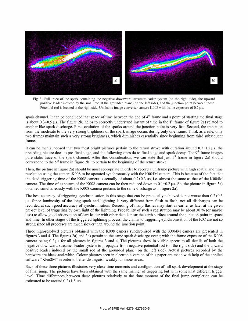
Three high-resolved pictures obtained with the K008 camera synchronised with the K004M camera are presented in figures 3 and 4. The figures 2a) and 3a) pertain to the same spark discharge event; with the frame exposure of the K008 camera being 0.2 µs for all pictures in figures 3 and 4. The pictures show in visible spectrum all details of both the negative downward streamer-leader system to propagate from negative potential rod (on the right side) and the upward positive leader induced by the small rod at the grounded plane (on the left side). Actual pictures recorded by the hardware are black-and-white. Colour pictures seen in electronic version of this paper are made with help of the applied software “Klen2M” in order to better distinguish weakly luminous areas.
Each of these three pictures illustrates very close time moments and configuration of full spark development at the stage of final jump. The pictures have been obtained with the same manner of triggering but with somewhat different trigger level. Time differences between these pictures relatively to the time moment of the final jump completion can be estimated to be around 0.2÷1.5 µs.
a) b)
Fig. 3. Full trace of the spark containing the negative downward streamer-leader system (on the right side), the upward positive leader induced by the small rod at the grounded plane (on the left side), and the junction point between those. Potential rod is located at the right side. Uniframe image converter camera K008 with frame exposure of 0.2 µs.
Proc. of SPIE Vol. 6279 62795D-5
The picture 3a) shows the main very transient sub-stage of the final jump. In addition to the central most intensive part of the streamer-leader system, there exist several weakly luminous leader traces (maybe, attempted leaders) directed from both sides to the junction point.
The picture 3b) shows completion of stage of the final jump. As well seen, the central single channel of the spark is split on two almost identical traces around the junction point. Also, several attempted branches of the upward streamer-leader system are well seen.
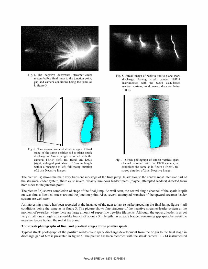
An interesting picture has been recorded at the instance of the next to last re-strike preceding the final jump, figure 4; all conditions being the same as in figure 3. The picture shows fine structure of the negative streamer-leader system at the moment of re-strike, where there are large amount of super-fine tree-like filaments. Although the upward leader is as yet very small, one straight streamer-like branch of about a 3 m length has already bridged remaining gap space between the negative leader tip and the rod at the plane.
3.3 Streak photographs of final and pre-final stages of the positive spark
Typical streak photograph of the positive rod-to-plane spark discharge development from the origin to the final stage in discharge gap of 6 m is presented in figure 5. The picture has been recorded with the streak camera FER14 instrumented
Fig. 4. The negative downward streamer-leader system before final jump to the junction point; gap and camera conditions being the same as in figure 3.
Fig. 5. Streak image of positive rod-to-plane spark discharge. Analog streak camera FER14 instrumented with the SU04 CCD-based readout system, total sweep duration being 100 µs.
Fig. 6. Two cross-correlated streak images of final stage of the same positive rod-to-plane spark discharge of 6 m in length recorded with the cameras FER14 (left, full trace) and K008 (right, enlarged part about of 3 m in length within a rectangle at left, full sweep duration of 2 µs). Negative images.
Fig. 7. Streak photograph of almost vertical spark channel recorded with the K008 camera; all conditions the same as in figure 6 (right), full sweep duration of 2 µs. Negative image.
Proc. of SPIE Vol. 6279 62795D-6
with a CCD-based readout system. The picture shows three bright re-strikes and return stroke trace as well as four steady-state segments between those.
Figure 6 (left) shows return stroke trace taken with the FER14 camera at conditions as in figure 5. Figure 6 (right) shows an enlarged part of the same spark discharge recorded simultaneously by the K008 camera with much better spatiotemporal resolution: full vertical spatial size of the picture being about of 3 m and full sweep duration of 2 µs. The FER14 camera was triggered by the primary flash radiated near the potential rod and the K008 camera done by the light radiated near the grounded plane in pre-final stage. With these preliminary experiments, an adjustment of the K008 camera has been made.
In order to have an acceptable quality of the streak photograph in the later case, very fine correlation should be provided between brightness of the spark trace, trigger level, responsivity and optical magnification of the camera. A successful attempt at the same conditions has been shown in figure 7. Almost vertical discharge trace is positioned in the middle of the picture; with all details of the final jump and return stroke well resolved. This picture allows us to determine the kinematic characteristics of both the final jump and the return stroke with acceptable accuracy (see below).
3.4 Frame photographs of separate re-strikes of the positive spark
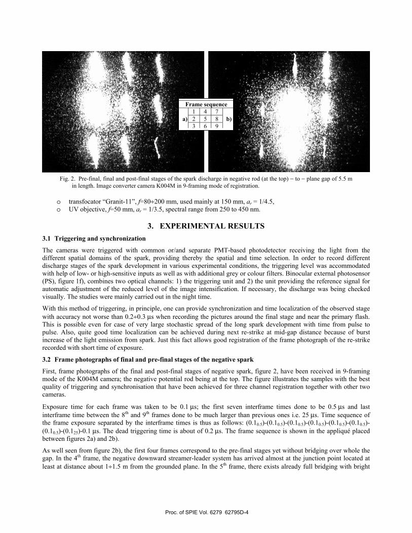
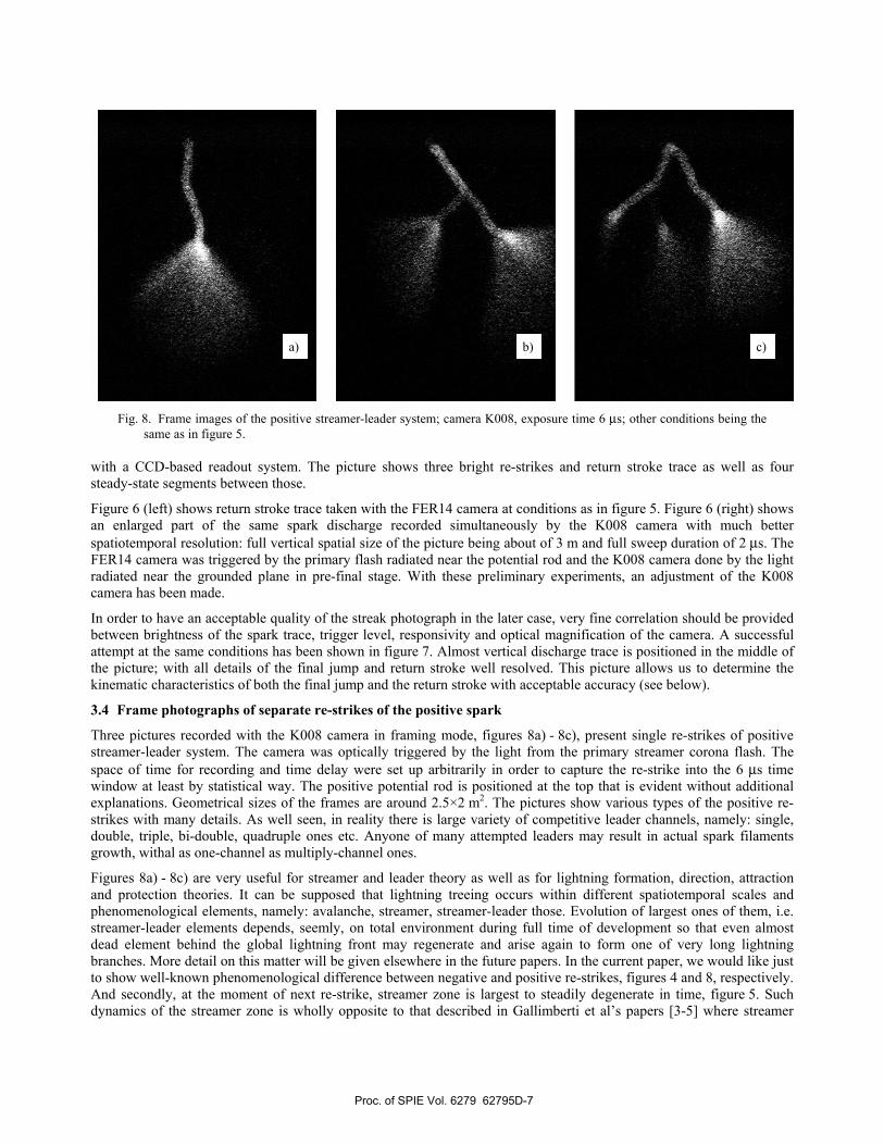
Three pictures recorded with the K008 camera in framing mode, figures 8a) - 8c), present single re-strikes of positive streamer-leader system. The camera was optically triggered by the light from the primary streamer corona flash. The space of time for recording and time delay were set up arbitrarily in order to capture the re-strike into the 6 µs time window at least by statistical way. The positive potential rod is positioned at the top that is evident without additional explanations. Geometrical sizes of the frames are around 2.5×2 m2. The pictures show various types of the positive re-strikes with many details. As well seen, in reality there is large variety of competitive leader channels, namely: single, double, triple, bi-double, quadruple ones etc. Anyone of many attempted leaders may result in actual spark filaments growth, withal as one-channel as multiply-channel ones.
Figures 8a) - 8c) are very useful for streamer and leader theory as well as for lightning formation, direction, attraction and protection theories. It can be supposed that lightning treeing occurs within different spatiotemporal scales and phenomenological elements, namely: avalanche, streamer, streamer-leader those. Evolution of largest ones of them, i.e. streamer-leader elements depends, seemly, on total environment during full time of development so that even almost dead element behind the global lightning front may regenerate and arise again to form one of very long lightning branches. More detail on this matter will be given elsewhere in the future papers. In the current paper, we would like just to show well-known phenomenological difference between negative and positive re-strikes, figures 4 and 8, respectively. And secondly, at the moment of next re-strike, streamer zone is largest to steadily degenerate in time, figure 5. Such dynamics of the streamer zone is wholly opposite to that described in Gallimberti et al’s papers [3-5] where streamer
a) b) c)
Fig. 8. Frame images of the positive streamer-leader system; camera K008, exposure time 6 µs; other conditions being the same as in figure 5.
Proc. of SPIE Vol. 6279 62795D-7
¼
zone is smallest at the moment of re-strike to increase in time up to sudden termination at some instant. This matter will be discussed later as well.
3.5 Full range streak photographs with the automatic adjustment of the image intensification being switched off
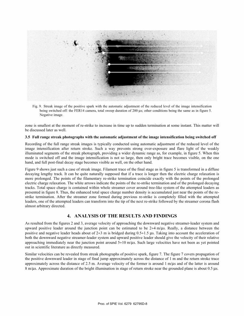
Recording of the full range streak images is typically conducted using automatic adjustment of the reduced level of the image intensification after return stroke. Such a way prevents strong over-exposure and flare light of the weakly illuminated segments of the streak photograph, providing a wider dynamic range as, for example, in figure 5. When this mode is switched off and the image intensification is not so large, then only bright trace becomes visible, on the one hand, and full post-final decay stage becomes visible as well, on the other hand.
Figure 9 shows just such a case of streak image. Filament trace of the final stage as in figure 5 is transformed in a diffuse decaying lengthy track. It can be quite naturally supposed that if a trace is longer then the electric charge relaxation is more prolonged. The points of the filamentary re-strike termination coincide exactly with the points of the prolonged electric charge relaxation. The white arrows indicate the points of the re-strike termination and of the prolonged decaying tracks. Total space charge is contained within whole streamer cover around tree-like system of the attempted leaders as presented in figure 8. Thus, the enhanced total space charge number density is accumulated just near the points of the re-strike termination. After the streamer zone formed during previous re-strike is completely filled with the attempted leaders, one of the attempted leaders can transform into the tip of the next re-strike followed by the streamer corona flash almost arbitrary directed.
4. ANALYSIS OF THE RESULTS AND FINDINGS As resulted from the figures 2 and 3, average velocity of approaching the downward negative streamer-leader system and upward positive leader around the junction point can be estimated to be 2÷4 m/µs. Really, a distance between the positive and negative leader heads about of 2÷3 m is bridged during 0.5÷1.5 µs. Taking into account the acceleration of both the downward negative streamer-leader system and upward positive leader should give the velocity of their relative approaching immediately near the junction point around 5÷10 m/µs. Such large velocities have not been as yet pointed out in scientific literature as directly measured.
Similar velocities can be revealed from streak photographs of positive spark, figure 7. The figure 7 covers propagation of the positive downward leader in stage of final jump approximately across the distance of 1 m and the return stroke trace approximately across the distance of 2.5 m. Average velocity of the former is around 1 m/µs and of the latter is around 8 m/µs. Approximate duration of the bright illumination in stage of return stroke near the grounded plane is about 0.5 µs.
Fig. 9. Streak image of the positive spark with the automatic adjustment of the reduced level of the image intensification being switched off: the FER14 camera, total sweep duration of 200 µs; other conditions being the same as in figure 5. Negative image.
Proc. of SPIE Vol. 6279 62795D-8
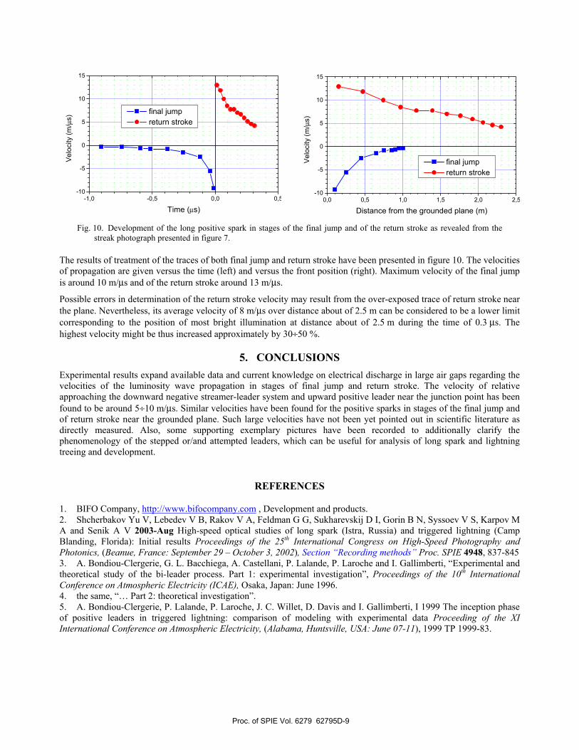
The results of treatment of the traces of both final jump and return stroke have been presented in figure 10. The velocities of propagation are given versus the time (left) and versus the front position (right). Maximum velocity of the final jump is around 10 m/µs and of the return stroke around 13 m/µs.
Possible errors in determination of the return stroke velocity may result from the over-exposed trace of return stroke near the plane. Nevertheless, its average velocity of 8 m/µs over distance about of 2.5 m can be considered to be a lower limit corresponding to the position of most bright illumination at distance about of 2.5 m during the time of 0.3 µs. The highest velocity might be thus increased approximately by 30÷50 %.
5. CONCLUSIONS Experimental results expand available data and current knowledge on electrical discharge in large air gaps regarding the velocities of the luminosity wave propagation in stages of final jump and return stroke. The velocity of relative approaching the downward negative streamer-leader system and upward positive leader near the junction point has been found to be around 5÷10 m/µs. Similar velocities have been found for the positive sparks in stages of the final jump and of return stroke near the grounded plane. Such large velocities have not been yet pointed out in scientific literature as directly measured. Also, some supporting exemplary pictures have been recorded to additionally clarify the phenomenology of the stepped or/and attempted leaders, which can be useful for analysis of long spark and lightning treeing and development.
REFERENCES
1. BIFO Company, http://www.bifocompany.com , Development and products. 2. Shcherbakov Yu V, Lebedev V B, Rakov V A, Feldman G G, Sukharevskij D I, Gorin B N, Syssoev V S, Karpov M A and Senik A V 2003-Aug High-speed optical studies of long spark (Istra, Russia) and triggered lightning (Camp Blanding, Florida): Initial results Proceedings of the 25th International Congress on High-Speed Photography and Photonics, (Beanue, France: September 29 – October 3, 2002), Section “Recording methods” Proc. SPIE 4948, 837-845 3. A. Bondiou-Clergerie, G. L. Bacchiega, A. Castellani, P. Lalande, P. Laroche and I. Gallimberti, “Experimental and theoretical study of the bi-leader process. Part 1: experimental investigation”, Proceedings of the 10th International Conference on Atmospheric Electricity (ICAE), Osaka, Japan: June 1996. 4. the same, “… Part 2: theoretical investigation”. 5. A. Bondiou-Clergerie, P. Lalande, P. Laroche, J. C. Willet, D. Davis and I. Gallimberti, I 1999 The inception phase of positive leaders in triggered lightning: comparison of modeling with experimental data Proceeding of the XI International Conference on Atmospheric Electricity, (Alabama, Huntsville, USA: June 07-11), 1999 TP 1999-83.
-1,0 -0,5 0,0 0,5-10
-5
0
5
10
15
final jump return stroke
Velo
city
(m/µ
s)
Time (µs)0,0 0,5 1,0 1,5 2,0 2,5
-10
-5
0
5
10
15
final jump return stroke
Velo
city
(m/µ
s)
Distance from the grounded plane (m)
Fig. 10. Development of the long positive spark in stages of the final jump and of the return stroke as revealed from the streak photograph presented in figure 7.
Proc. of SPIE Vol. 6279 62795D-9