Embed Size (px)
Citation preview
FLOOD BARRIER SYSTEMS
© Blobel Umwelttechnik GmbH - BLOBEL Environmental Engineering
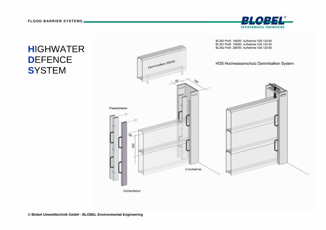
HIGHWATER DEFENCE SYSTEM

FLOOD BARRIER SYSTEMS
© BLOBEL Umwelttechnik GmbH – BLOBEL Environmental Engineering Page 2
HDS - HIGHWATER DEFENCE SYSTEM Overview 1. HDS 150/50 BL360 Page 3
2. HDS 150/80 BL361 Page 4
3. HDS 200/50 BL362 Page 5
Details 4. Horizontal details Page 6
5. Vertical details Page 7

FLOOD BARRIER SYSTEMS
© BLOBEL Umwelttechnik GmbH – BLOBEL Environmental Engineering Page 3
1. HDS 150/50 BL 360
Highwater Defence System Aluminium Profile 150/50 Stainless steel U-Post 120/60
The HDS Barrier System was developed for optimal integration within new and old facilities. During design, special attention was given to inconspicuousness and protection from vandalism. In the base version, u-posts are made from stainless steel material (304). The u-posts can be bolted directly to the wall or recessed and contain no seals, pressure rails, nuts, bolts or any other fittings which may be tampered with. The light weight barrier panels are constructed from AlMgSi0,5 aluminium making them easy to use and ensuring fast implementation. In order to seal the barrier panels against the u-posts, a unique sealing and pressure rail system has been developed. The system simply slides into the u-post and pressure is applied to fix the barrier panels against the sealing rail. The design of the system allows sealing in either direction depending on flood mitigation requirements. The lowest barrier segment is fitted with a special, highly flexible and durable seal. Ground unevenness of up to 20mm can be accommodated with ease. System specific pressure screws are used to apply downward force and made from stainless steel. Remaining barrier panels are fitted with a seal based on EPDM.
HDS 150/50
Installation within the opening (iL) Barrier body length LBi = LW - 60mm
Installation in front of the opening (aL)
Barrier body length LBa = LW + 100mm
FLOOD BARRIER SYSTEMS
© BLOBEL Umwelttechnik GmbH – BLOBEL Environmental Engineering Page 4
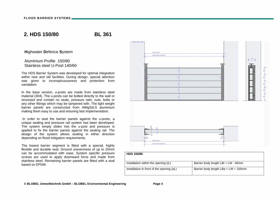
2. HDS 150/80 BL 361
Highwater Defence System Aluminium Profile 150/80 Stainless steel U-Post 140/60
The HDS Barrier System was developed for optimal integration within new and old facilities. During design, special attention was given to inconspicuousness and protection from vandalism. In the base version, u-posts are made from stainless steel material (304). The u-posts can be bolted directly to the wall or recessed and contain no seals, pressure rails, nuts, bolts or any other fittings which may be tampered with. The light weight barrier panels are constructed from AlMgSi0,5 aluminium making them easy to use and ensuring fast implementation. In order to seal the barrier panels against the u-posts, a unique sealing and pressure rail system has been developed. The system simply slides into the u-post and pressure is applied to fix the barrier panels against the sealing rail. The design of the system allows sealing in either direction depending on flood mitigation requirements. The lowest barrier segment is fitted with a special, highly flexible and durable seal. Ground unevenness of up to 20mm can be accommodated with ease. System specific pressure screws are used to apply downward force and made from stainless steel. Remaining barrier panels are fitted with a seal based on EPDM.
HDS 150/80
Installation within the opening (iL) Barrier body length LBi = LW - 60mm
Installation in front of the opening (aL)
Barrier body length LBa = LW + 100mm
FLOOD BARRIER SYSTEMS
© BLOBEL Umwelttechnik GmbH – BLOBEL Environmental Engineering Page 5
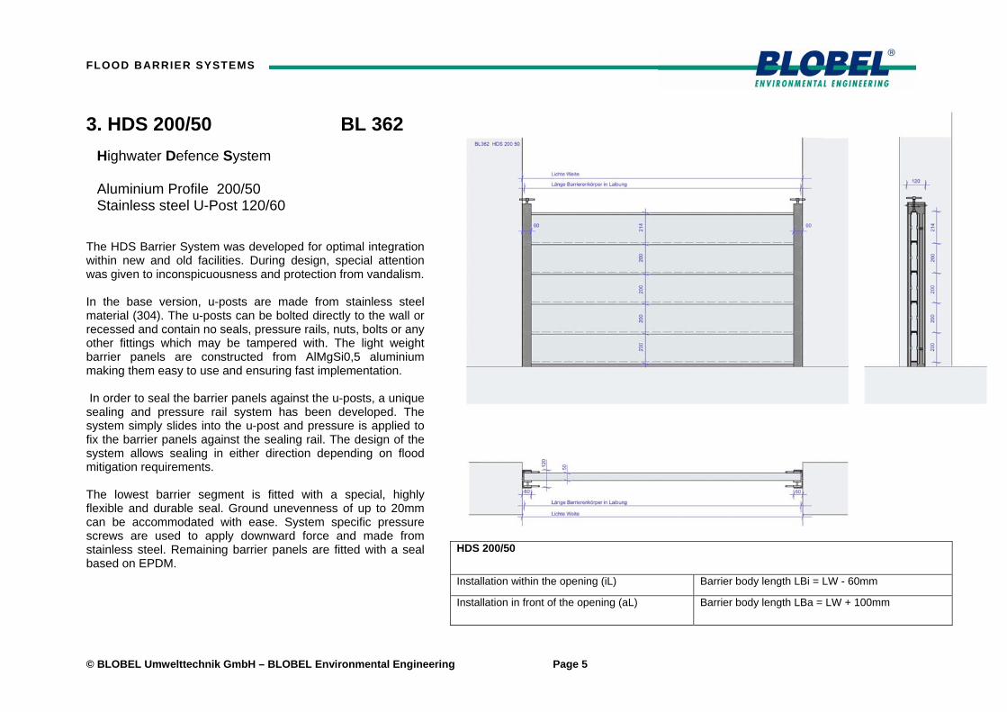
3. HDS 200/50 BL 362
Highwater Defence System Aluminium Profile 200/50 Stainless steel U-Post 120/60
The HDS Barrier System was developed for optimal integration within new and old facilities. During design, special attention was given to inconspicuousness and protection from vandalism. In the base version, u-posts are made from stainless steel material (304). The u-posts can be bolted directly to the wall or recessed and contain no seals, pressure rails, nuts, bolts or any other fittings which may be tampered with. The light weight barrier panels are constructed from AlMgSi0,5 aluminium making them easy to use and ensuring fast implementation. In order to seal the barrier panels against the u-posts, a unique sealing and pressure rail system has been developed. The system simply slides into the u-post and pressure is applied to fix the barrier panels against the sealing rail. The design of the system allows sealing in either direction depending on flood mitigation requirements. The lowest barrier segment is fitted with a special, highly flexible and durable seal. Ground unevenness of up to 20mm can be accommodated with ease. System specific pressure screws are used to apply downward force and made from stainless steel. Remaining barrier panels are fitted with a seal based on EPDM.
HDS 200/50
Installation within the opening (iL) Barrier body length LBi = LW - 60mm
Installation in front of the opening (aL)
Barrier body length LBa = LW + 100mm
FLOOD BARRIER SYSTEMS
© BLOBEL Umwelttechnik GmbH – BLOBEL Environmental Engineering Page 6
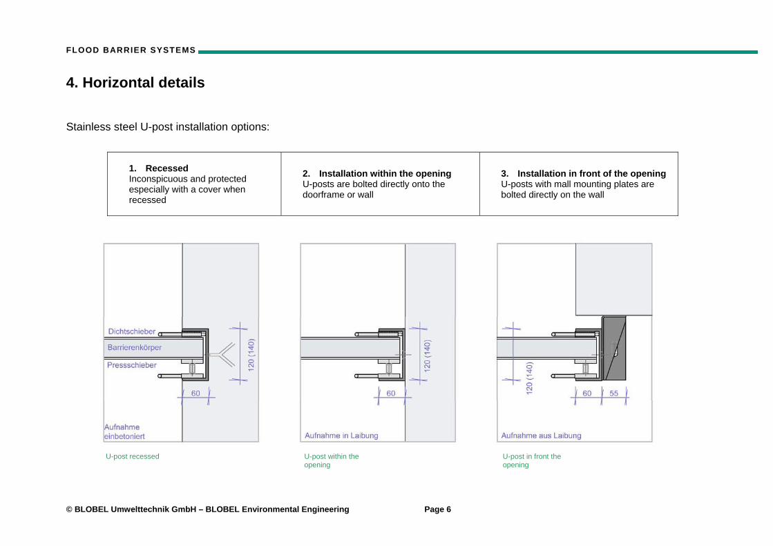
4. Horizontal details Stainless steel U-post installation options:
1. Recessed Inconspicuous and protected especially with a cover when recessed
2. Installation within the opening U-posts are bolted directly onto the doorframe or wall
3. Installation in front of the opening U-posts with mall mounting plates are bolted directly on the wall
U-post recessed U-post within the opening
U-post in front the opening
FLOOD BARRIER SYSTEMS
© BLOBEL Umwelttechnik GmbH – BLOBEL Environmental Engineering Page 7
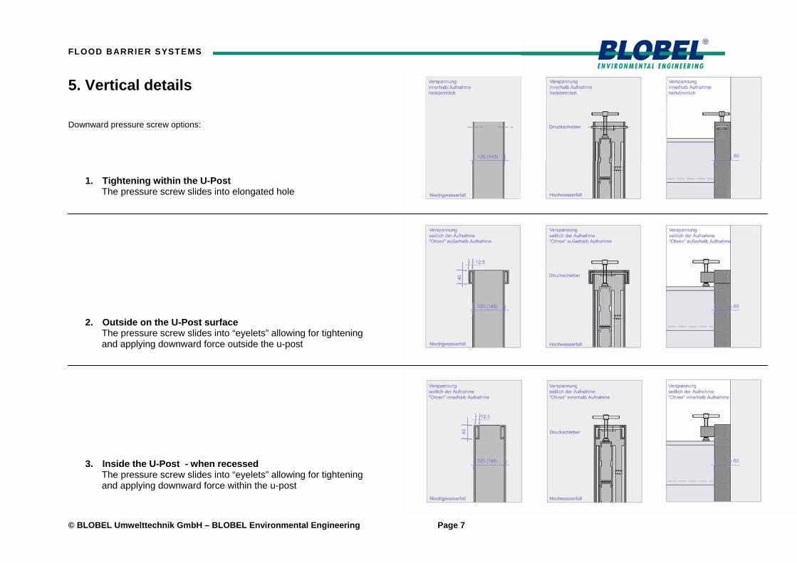
5. Vertical details Downward pressure screw options:
1. Tightening within the U-Post The pressure screw slides into elongated hole
2. Outside on the U-Post surface The pressure screw slides into “eyelets” allowing for tightening and applying downward force outside the u-post
3. Inside the U-Post - when recessed The pressure screw slides into “eyelets” allowing for tightening and applying downward force within the u-post
FLOOD BARRIER SYSTEMS
© Blobel Umwelttechnik GmbH Page 8
6. Larger openings
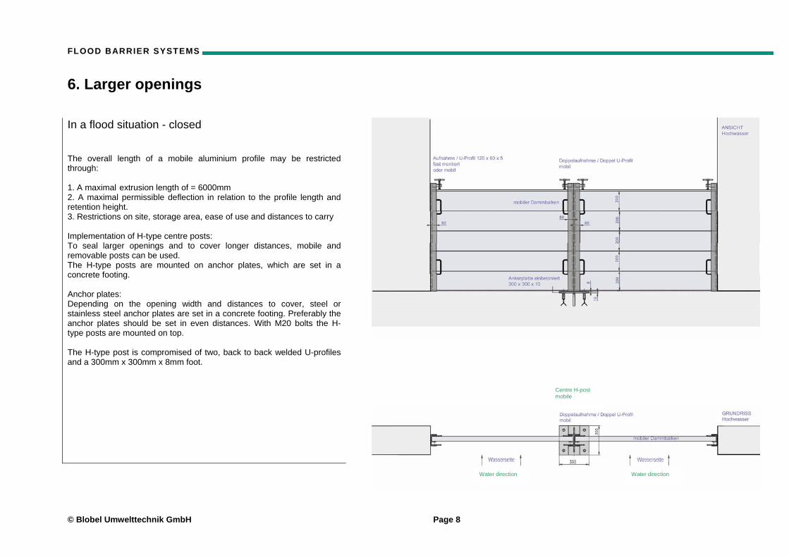
In a flood situation - closed The overall length of a mobile aluminium profile may be restricted through: 1. A maximal extrusion length of = 6000mm 2. A maximal permissible deflection in relation to the profile length and retention height. 3. Restrictions on site, storage area, ease of use and distances to carry Implementation of H-type centre posts: To seal larger openings and to cover longer distances, mobile and removable posts can be used. The H-type posts are mounted on anchor plates, which are set in a concrete footing. Anchor plates: Depending on the opening width and distances to cover, steel or stainless steel anchor plates are set in a concrete footing. Preferably the anchor plates should be set in even distances. With M20 bolts the H- type posts are mounted on top. The H-type post is compromised of two, back to back welded U-profiles and a 300mm x 300mm x 8mm foot.
Water direction Water direction
Centre H-post mobile
FLOOD BARRIER SYSTEMS
© BLOBEL Umwelttechnik GmbH – BLOBEL Environmental Engineering Page 9
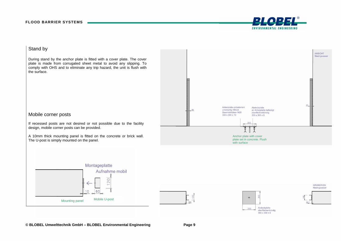
Stand by During stand by the anchor plate is fitted with a cover plate. The cover plate is made from corrugated sheet metal to avoid any slipping. To comply with OHS and to eliminate any trip hazard, the unit is flush with the surface. Mobile corner posts If recessed posts are not desired or not possible due to the facility design, mobile corner posts can be provided. A 10mm thick mounting panel is fitted on the concrete or brick wall. The U-post is simply mounted on the panel.
Mounting panel Mobile U-post
Anchor plate with cover plate set in concrete. Flush with surface

FLOOD BARRIER SYSTEMS
© Blobel Umwelttechnik GmbH - BLOBEL Environmental Engineering
7. General setup instructions
The following instructions are based on permanent installed corner posts. Systems specific setup instructions are provided with each HDS Flood Barrier System supplied. Setup - closing
• If available, mount centre H-type post with 4 M20x50 bolts on the anchor plate
• Implement lowest flood barrier panel between the U-posts (= Panel with the largest seal)
• Slide in pressure rail (opposite the water side)
• Depending on retention height, implement remaining barrier panels – simply stack on top of each other
• Slide in pressure rail
• Apply downward pressure screws in U-posts – pressure screws slide into eyelets
• Compress lowest barrier seal to about 10-20%
• Extend pressure rail to compress seal in U-posts – pressure rail is fitted with screws and expands
Opening - demount
• Loosen downward pressure from vertical pressure screw
• Loosen screws at pressure rail
• Remove pressure rail from U-post
• Remove sealing rail form U-Post
• Remove all barrier panels
• Dismount relevant H-posts and apply cover plates
• If necessary clean and hose down post and flood barrier panels
• Store for easy access

FLOOD BARRIER SYSTEMS
© BLOBEL Umwelttechnik GmbH – BLOBEL Environmental Engineering Page 11
Notes:

Europe
Blobel Umwelttechnik GmbH
Ziegeleistraße 586368 Gersthofen, Germany
Telephone: +49 (0)821 498190-0Telefax: +49 (0)821 498190-30
email: [email protected]: www.blobel.de
North America / Canada
BLOBEL Environmental Engineering LLC
270 Presidential DriveWilmington, Delaware 19807, USA
Telephone: +1 302-353-1555Telefax: +1 302-288-3753
email: [email protected]: www.blobel.com
Asia / Pacific / South America
Blobel Environmental Engineering
6/41 Belgrave StreetSydney NSW 2024, Australia
Telephone: +61 (0)2/93 69 35 04Mobile: +61 (0) 4 19 27 94 81
email: [email protected]: www.blobel.com