Embed Size (px)
Citation preview
Hot Water Temperature MaintenanceProduct Selection and Design Guide

A Solutions Company Tyco Thermal Controls provides complete heat tracing and specialty wiring solutions for the industrial, commercial, and residential markets. Employing over one thousand people around the world, Tyco Thermal Controls is the global leader in total solutions.
Worldwide Approach With operations in 48 countries and worldwide experience, Tyco Thermal Controls can support your project efforts anywhere, anytime. Whether it is state-of-the-art products or turnkey services, Tyco Thermal Controls has the solution.
The Raychem Brand Raychem is the leading brand in electric heat-tracing solutions.In 1971, Raychem Corporation introduced the world’s firstself-regulating heat-tracing products. By 1980, self-regulatingheating cables had become the industry standard worldwide. Today, Raychem brand heating cables continue to be recognized as the leading solution for Hot Water Temperature Maintenance, Pipe Freeze Protection, Snow Melting, Roof & Gutter De-icing, and Floor Warming applications.
Raychem HWAT System The HWAT system provides a simple way to keep water at a consistent warm temperature, regardless of how complex the building. Already installed in more than 100,000 hotels, hospitals, apartments, offices, schools, nursing homes, and correctional facilities around the world, the HWAT system offers a simple, reliable alterna-tive to recirculation.

Comfortable and energy efficientToday’s hot water system requirements focus on users’ comfort as well as operational and energy savings. With this in mind, the Raychem HWAT System keeps the hot water at the right temperature everywhere in the building while saving energy at the same time.
Simple, effective and intelligentThe HWAT system ensures an abundant supply of hot water at the same temperature throughout the building while eliminating the need for return piping. The HWAT heating cable is attached to a hot water pipe, keeping the water at the desired temperature. The cable continuously senses the temperature of the pipes, and will modify its heat output accordingly. Combined with the HWAT-ECO or ACCS-30 controller, HWAT is a sophisticated temperature and energy management system. The HWAT system provides real energy savings and delivers quality hot water.
Return piping, balancing valves and pumps required in a recirculation system are eliminated in an HWAT System, branches and risers can be traced easily, as indicated in the above illustration.
The Optimal Hot Water Temperature Maintenance System
HWAT systems can be found in a variety of commercial buildings, including hospitals, office and retail buildings and schools.

Less energy consumption • Theself-regulatingtechnologymanagestheheatoutputlocally. • Heatlossislowerwithonly1pipeasopposedtoarecirculation
system that requires return piping. • Becausearecirculationpumpisnotneeded,energyissaved. • Waterheaterefficiencyisoptimized,therefore,asmallerwaterheater
can be used. • Becausehotwaterismaintainedalongtheentirelengthofsupply
pipe, there is no need to overheat the supply water at the beginning of the cycle, as with a recirculation system.
The HWAT-ECO electronic controller calculates the amount of “on” time required to maintain the desired temperature. When water usage is low, maintain temperatures can be reduced. When water usage is high and hot water is flowing from the water heater to the point of use without delay, the heating cable can be turned off.
Economical in design and installationA Single pipe: no need for complex pressure and balance calculations or drawings which saves design time.
Simple Design: The length of pipe corresponds to the length of heating cable that is required.
Easy to install: the system uses few components. The cable is attached directly onto the hot water pipe under the thermal insulation. No need for return pipe works, valves or pumps!
Fast connection: the RayClic system allows for connections to be made quickly.
Intelligent Energy & Cost Saving
The lengths of pipe correspond to the lengths of heating cable needed.

Automatic temperature adjustmentThe self-regulating heating cable really is the heart of the system. It senses the temperature of the pipes and modifies the heat output accordingly. The self-regulating cable can be installed on all the supply piping to ensure that instant hot water is available at every tap.
Optimized for efficient energy usageThe easy-to-program HWAT-ECO or ACCS-30 controller modulates the heating cable in accordance with the specific requirements of your building. It even monitors water heater temperatures to ensure that the system is only used for temperature maintenance; not for heating the water. This minimizes energy consumption.
Flexible temperature control: variable temperature maintenance in the range 105–140°F (40–60°C).Building Management System (BMS) compatibility: The HWAT-ECO controller allows connection to a BMS system, enabling remote tempera-ture maintenance and continual feedback through the alarm contacts.Monitors the water heater temperature: activates an alarm and adjusts the maintain temperature setpoint automatically when the water heater temperature falls below the maintain temperature. Nine building specific-programs: make programming of complex build-ings easier.Master/slave function: allows one controller to network with up to eight additional controllers for fast programming.
Simplified InstallationThe RayClic connection system cuts installation time considerably. Power, splice and tee connections are made easily and reliably.
Tightening two screws is all it takes. • Noneedforspecialtools. • Minimalheatingcablestripping. • No“heat-shrink”components.
The Secret is in the Heating Cable
Top: HWAT-R2 heating cable. Center: HWAT-ECO controller. Bottom: RayClic connection kit.
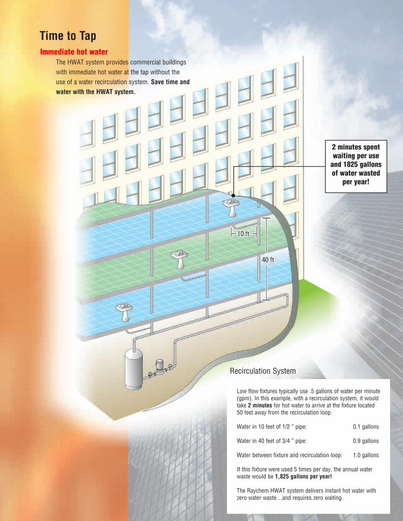
Low flow fixtures typically use .5 gallons of water per minute (gpm). In this example, with a recirculation system, it would take 2 minutes for hot water to arrive at the fixture located 50 feet away from the recirculation loop.
Waterin10feetof1/2”pipe: 0.1gallons
Waterin40feetof3/4”pipe: 0.9gallons
Water between fixture and recirculation loop: 1.0 gallons
If this fixture were used 5 times per day, the annual water waste would be 1,825 gallons per year!
The Raychem HWAT system delivers instant hot water with zero water waste…and requires zero waiting.
Time to Tap
Recirculation System
Immediate hot waterThe HWAT system provides commercial buildings with immediate hot water at the tap without the use of a water recirculation system. Save time and water with the HWAT system.
2 minutes spent waiting per use
and 1825 gallons of water wasted
per year!
1.
Desig
n G
uid
e2.
Desig
n N
ote
s3.
Desig
n E
xam
ple
s4.
Tech
nica
l Data
sheets
5.
Exp
anded C
apabilitie
s6.
Specifi ca
tion
7.
Warra
nty
www.tycothermal.com
Raychem HWAT Hot Water
Temperature Maintenance
System
The Raychem HWAT System is a hot water temperature maintenance system that provides immediate hot water without the use of a water recirculation system. This product selection and design guide provides all the information necessary to select and design an HWAT system. For information regarding other products and applications, contact Tyco Thermal Controls at (800) 545-6258. Also, visit our web site at www.tycothermal.com.
Contents
Section 1: Design Guide . . . . . . . . . . . . . . . . . . . . . . . . . . . . . . . . . . . . . . . . . . . . . . . . . 1-1Section 2: Application Design Notes
2.1: Hot Water Maintenance System: Insulation Schedule for Non-static Supply Piping . . . . . . . . . . . . . . . . . . . . . . . . . . . . . . . . . . . . . . . . . . 2-12.2: Hybrid Hot Water Maintenance System: A combination of Recirculation and HWAT Designs . . . . . . . . . . . . . . . . . . . . . . . . . . . . . . . . . . . . . . . . . . . . . . 2-32.3: Hot Water Maintenance System on Rigid Plastic Pipes . . . . . . . . . . . . . . . . . . . 2-5
Section 3: Design Examples . . . . . . . . . . . . . . . . . . . . . . . . . . . . . . . . . . . . . . . . . . . . . . 3-1Section 4: Technical Data Sheets
HWAT Heating Cables . . . . . . . . . . . . . . . . . . . . . . . . . . . . . . . . . . . . . . . . . . . . . . . . . . . . 4-1HWAT-ECO . . . . . . . . . . . . . . . . . . . . . . . . . . . . . . . . . . . . . . . . . . . . . . . . . . . . . . . . . . . . . 4-3ACCS-30 Control System . . . . . . . . . . . . . . . . . . . . . . . . . . . . . . . . . . . . . . . . . . . . . . . . . . 4-6RayClic Connection Kits and Accessories . . . . . . . . . . . . . . . . . . . . . . . . . . . . . . . . . . . . 4-12
Section 5: Expanded HWAT-ECO Electronic Controller Capabilities . . . . . . . . . . . . . . . . . . . . . 5-1Section 6: Specifi cation . . . . . . . . . . . . . . . . . . . . . . . . . . . . . . . . . . . . . . . . . . . . . . . . . . . . . . 6-1Section 7: Limited Warranty . . . . . . . . . . . . . . . . . . . . . . . . . . . . . . . . . . . . . . . . . . . . . . . . . . . 7-1

RAYCHEM HWAT HOT WATER TEMPERATURE MAINTENANCE SYSTEM
www.tycothermal.com
1. D
esig
n G
uid
e2.
Desig
n N
ote
s3.
Desig
n E
xam
ple
s4.
Tech
nica
l Data
sheets
5.
Exp
anded C
apabilitie
s6.
Specifi ca
tion
7.
Warra
nty
H57510 2/12 www.tycothermal.com 1-1
Section 1:
Design Guide
This step-by-step design guide provides the tools necessary to design a Raychem HWAT Hot Water Temperature Maintenance System. For additional information, contact your Tyco Thermal Controls representative or phone Tyco Thermal Controls at (800) 545-6258. Also, visit our web site at www.tycothermal.com.
Section Contents
Introduction . . . . . . . . . . . . . . . . . . . . . . . . . . . . . . . . . . . . . . . . . . . . . . . . . . . . . . . . . . . . 1-1Typical Applications . . . . . . . . . . . . . . . . . . . . . . . . . . . . . . . . . . . . . . . . . . . . . . . . . . . . 1-2Approvals and Code Compliance . . . . . . . . . . . . . . . . . . . . . . . . . . . . . . . . . . . . . . . . . . 1-2Safety Guidelines . . . . . . . . . . . . . . . . . . . . . . . . . . . . . . . . . . . . . . . . . . . . . . . . . . . . . . 1-2Ground-Fault Protection . . . . . . . . . . . . . . . . . . . . . . . . . . . . . . . . . . . . . . . . . . . . . . . . . 1-3Design Requirements . . . . . . . . . . . . . . . . . . . . . . . . . . . . . . . . . . . . . . . . . . . . . . . . . . . 1-3
System Overview . . . . . . . . . . . . . . . . . . . . . . . . . . . . . . . . . . . . . . . . . . . . . . . . . . . . . . . . 1-3HWAT Electronic Controllers . . . . . . . . . . . . . . . . . . . . . . . . . . . . . . . . . . . . . . . . . . . . . 1-4HWAT Heating Cables . . . . . . . . . . . . . . . . . . . . . . . . . . . . . . . . . . . . . . . . . . . . . . . . . . . 1-4RayClic Connection Kits . . . . . . . . . . . . . . . . . . . . . . . . . . . . . . . . . . . . . . . . . . . . . . . . . 1-5
Design Guidelines . . . . . . . . . . . . . . . . . . . . . . . . . . . . . . . . . . . . . . . . . . . . . . . . . . . . . . . 1-5Before You Begin . . . . . . . . . . . . . . . . . . . . . . . . . . . . . . . . . . . . . . . . . . . . . . . . . . . . . . 1-6
Introduction
The Raychem HWAT System is a hot water temperature maintenance system that utilizes an electronic controller, self-regulating electric heating cables, and an easy-to-install set of connection kits to provide commercial buildings with immediate hot water at the tap without the use of a water recirculation system.
Recirculation systems require the water heater temperature to be at least fi ve degrees above the maintain temperature to compensate for the heat that is lost in the recirculation loop. With HWAT systems, the water in the supply pipe is maintained at a constant temperature along the entire length of the supply pipe so heating the water above the maintain temperature is not required. Recirculation systems also require return lines, pumps, and balancing valves, all of which are all unnecessary with HWAT.
A key component of the HWAT system is the HWAT-ECO controller. In addition to providing fl exible temperature control, the HWAT-ECO provides energy savings; a heat-up cycle that increases the water temperature in stagnant pipes; Building Management System (BMS) interface; alarm relay to signal power, temperature, or communication problems; a water heater sensor function; and nine predefi ned programs that can be customized by the user.
SECTION 1: DESIGN GUIDE
1-2 www.tycothermal.com H57510 2/12
Typical Applications
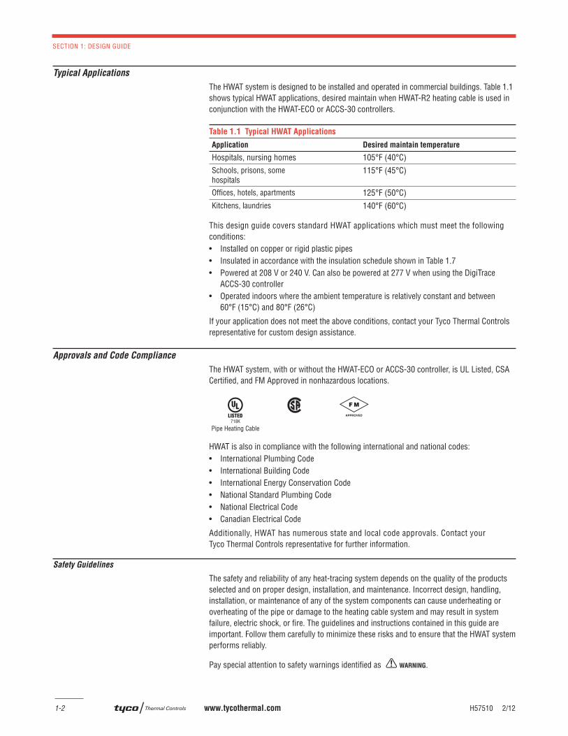
The HWAT system is designed to be installed and operated in commercial buildings. Table 1.1 shows typical HWAT applications, desired maintain when HWAT-R2 heating cable is used in conjunction with the HWAT-ECO or ACCS-30 controllers.
Table 1.1 Typical HWAT Applications
Application Desired maintain temperature
Hospitals, nursing homes 105°F (40°C)Schools, prisons, some hospitals
115°F (45°C)
Offi ces, hotels, apartments 125°F (50°C)Kitchens, laundries 140°F (60°C)
This design guide covers standard HWAT applications which must meet the following conditions:• Installed on copper or rigid plastic pipes • Insulated in accordance with the insulation schedule shown in Table 1.7 • Powered at 208 V or 240 V. Can also be powered at 277 V when using the DigiTrace
ACCS-30 controller• Operated indoors where the ambient temperature is relatively constant and between
60°F (15°C) and 80°F (26°C)
If your application does not meet the above conditions, contact your Tyco Thermal Controls representative for custom design assistance.
Approvals and Code Compliance
The HWAT system, with or without the HWAT-ECO or ACCS-30 controller, is UL Listed, CSA Certifi ed, and FM Approved in nonhazardous locations.
HWAT is also in compliance with the following international and national codes:• International Plumbing Code• International Building Code• International Energy Conservation Code• National Standard Plumbing Code• National Electrical Code• Canadian Electrical Code
Additionally, HWAT has numerous state and local code approvals. Contact your Tyco Thermal Controls representative for further information.
Safety Guidelines
The safety and reliability of any heat-tracing system depends on the quality of the products selected and on proper design, installation, and maintenance. Incorrect design, handling, installation, or maintenance of any of the system components can cause underheating or overheating of the pipe or damage to the heating cable system and may result in system failure, electric shock, or fi re. The guidelines and instructions contained in this guide are important. Follow them carefully to minimize these risks and to ensure that the HWAT system performs reliably.
Pay special attention to safety warnings identifi ed as WARNING.
Pipe Heating Cable718K
H57510 2/12 www.tycothermal.com 1-3
System Overview
1. D
esig
n G
uid
e
Ground-Fault Protection
To minimize the danger of fi re from sustained electrical arcing if the heating cable is damaged or improperly installed, and to comply with Tyco Thermal Controls requirements, agency certifi cations, and national electrical codes, ground-fault equipment protection must be used on each heating cable branch circuit. Arcing may not be stopped by conventional breakers.
Design Requirements
To comply with warranty requirements, the design and installation of the HWAT system must be in accordance with this guide and the additional documents listed below:
• HWAT-ECO Installation and Operations Manual (H57340)
• HWAT System Installation and Operations Manual (H57548)
• RayClic Connection Kit Installation Instructions (H55388 and H55092)
Installation documents are shipped with the respective products and are also available via the Tyco Thermal Controls web site at www.tycothermal.com.
System Overview
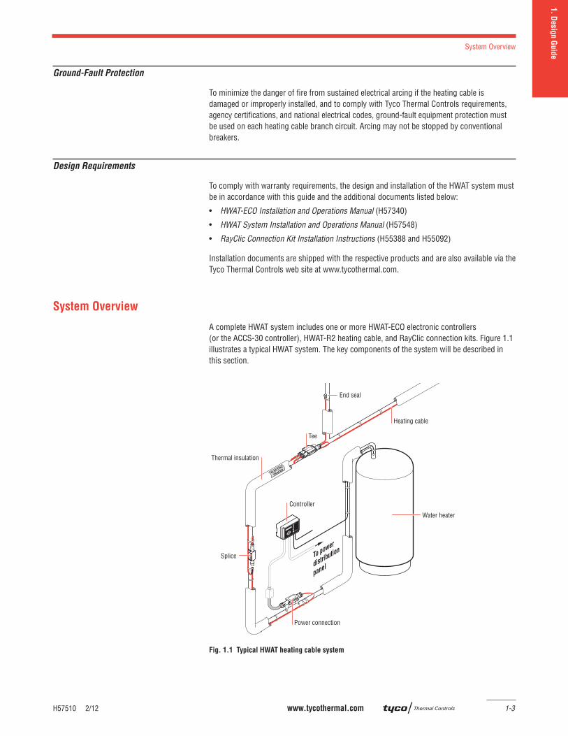
A complete HWAT system includes one or more HWAT-ECO electronic controllers (or the ACCS-30 controller), HWAT-R2 heating cable, and RayClic connection kits. Figure 1.1 illustrates a typical HWAT system. The key components of the system will be described in this section.
Fig. 1.1 Typical HWAT heating cable system
Splice To power
distributio
n
panel
End seal
Tee
Thermal insulation
Heating cable
Water heater
Power connection
Controller
SECTION 1: DESIGN GUIDE
1-4 www.tycothermal.com H57510 2/12
HWAT Electronic Controllers
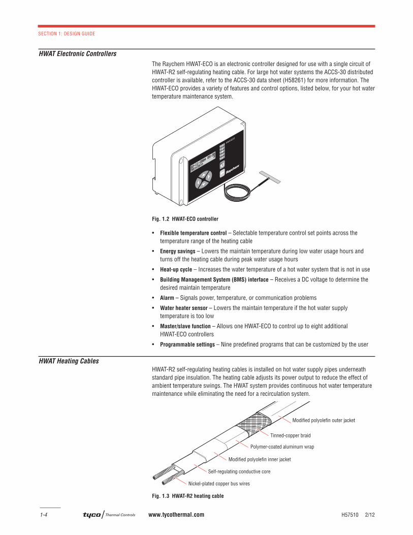
The Raychem HWAT-ECO is an electronic controller designed for use with a single circuit of HWAT-R2 self-regulating heating cable. For large hot water systems the ACCS-30 distributed controller is available, refer to the ACCS-30 data sheet (H58261) for more information. The HWAT-ECO provides a variety of features and control options, listed below, for your hot water temperature maintenance system.
Fig. 1.2 HWAT-ECO controller
• Flexible temperature control – Selectable temperature control set points across the temperature range of the heating cable
• Energy savings – Lowers the maintain temperature during low water usage hours and turns off the heating cable during peak water usage hours
• Heat-up cycle – Increases the water temperature of a hot water system that is not in use
• Building Management System (BMS) interface – Receives a DC voltage to determine the desired maintain temperature
• Alarm – Signals power, temperature, or communication problems
• Water heater sensor – Lowers the maintain temperature if the hot water supply temperature is too low
• Master/slave function – Allows one HWAT-ECO to control up to eight additional HWAT-ECO controllers
• Programmable settings – Nine predefi ned programs that can be customized by the user
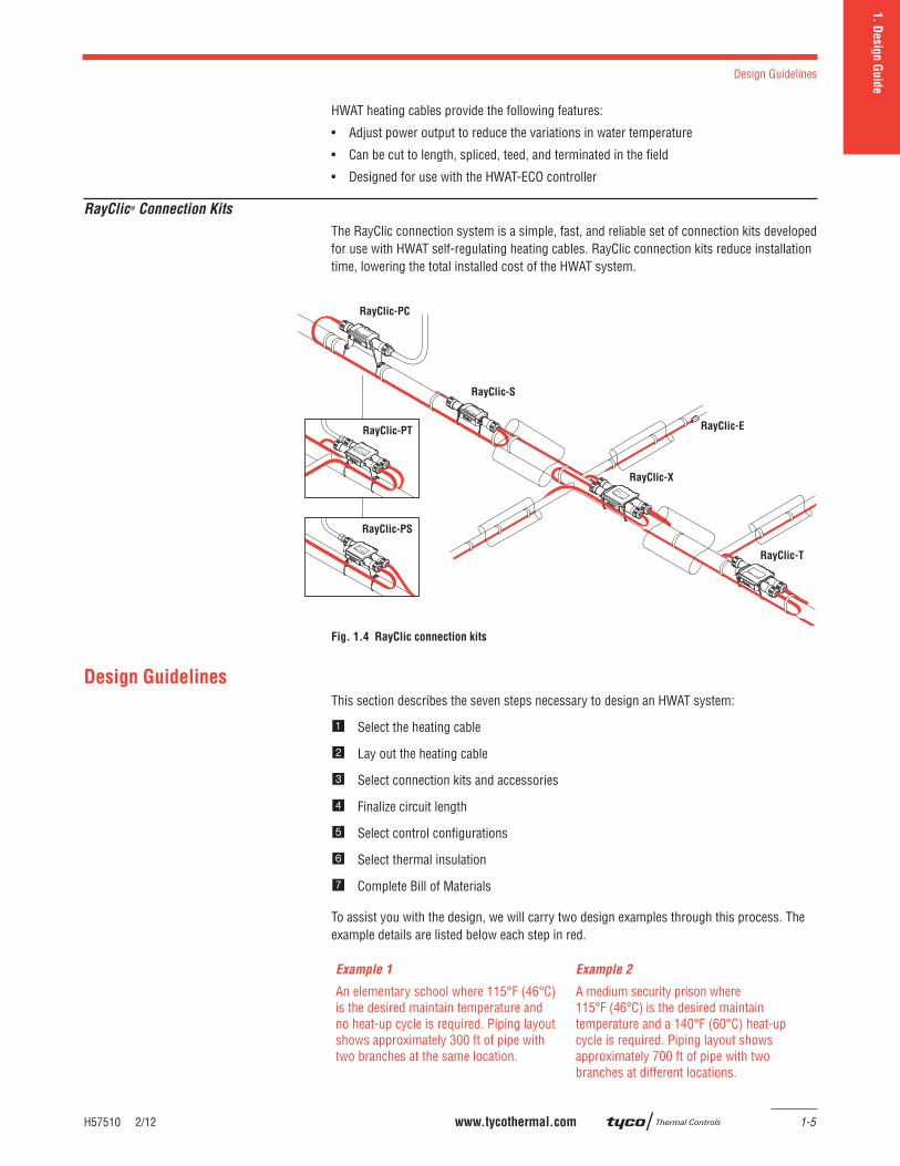
HWAT Heating Cables
HWAT-R2 self-regulating heating cables is installed on hot water supply pipes underneath standard pipe insulation. The heating cable adjusts its power output to reduce the effect of ambient temperature swings. The HWAT system provides continuous hot water temperature maintenance while eliminating the need for a recirculation system.
Fig. 1.3 HWAT-R2 heating cable
Nickel-plated copper bus wires
Self-regulating conductive core
Polymer-coated aluminum wrap
Tinned-copper braid
Modified polyolefin outer jacket
Modified polyolefin inner jacket
H57510 2/12 www.tycothermal.com 1-5
Design Guidelines
1. D
esig
n G
uid
e
HWAT heating cables provide the following features:
• Adjust power output to reduce the variations in water temperature
• Can be cut to length, spliced, teed, and terminated in the fi eld
• Designed for use with the HWAT-ECO controller
RayClic® Connection Kits
The RayClic connection system is a simple, fast, and reliable set of connection kits developed for use with HWAT self-regulating heating cables. RayClic connection kits reduce installation time, lowering the total installed cost of the HWAT system.
Fig. 1.4 RayClic connection kits
Design Guidelines
This section describes the seven steps necessary to design an HWAT system:
Select the heating cable
Lay out the heating cable
Select connection kits and accessories
Finalize circuit length
Select control confi gurations
Select thermal insulation
Complete Bill of Materials
To assist you with the design, we will carry two design examples through this process. The example details are listed below each step in red.
Example 1 Example 2
An elementary school where 115°F (46°C)is the desired maintain temperature and no heat-up cycle is required. Piping layout shows approximately 300 ft of pipe with two branches at the same location.
A medium security prison where 115°F (46°C) is the desired maintain temperature and a 140°F (60°C) heat-up cycle is required. Piping layout shows approximately 700 ft of pipe with two branches at different locations.
RayClic-PT
RayClic-PC
RayClic-S
RayClic-X
RayClic-T
RayClic-PS
RayClic-E
SECTION 1: DESIGN GUIDE
1-6 www.tycothermal.com H57510 2/12
Before You Begin
Before you begin designing your HWAT system, gather this necessary information:
• Desired maintain temperature
• Indoor ambient temperature
• Supply voltage
• Piping layout
• Total pipe length
• Pipe diameters
HWAT System Design
1. Select heating cable
6. Select insulation
2. Lay out the heating cable
3. Select connection kits and accessories
4. Finalize circuit length
5. Select control configuration
7. Complete Bill of Materials
Step Select heating cable
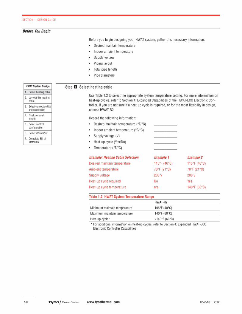
Use Table 1.2 to select the appropriate system temperature setting. For more information on heat-up cycles, refer to Section 4: Expanded Capabilities of the HWAT-ECO Electronic Con-troller. If you are not sure if a heat-up cycle is required, or for the most fl exibility in design, choose HWAT-R2.
Record the following information:
• Desired maintain temperature (°F/°C) _____________
• Indoor ambient temperature (°F/°C) _____________
• Supply voltage (V) _____________
• Heat-up cycle (Yes/No) _____________
• Temperature (°F/°C) _____________
Example: Heating Cable Selection Example 1 Example 2
Desired maintain temperature 115°F (46°C) 115°F (46°C)
Ambient temperature 70°F (21°C) 70°F (21°C)
Supply voltage 208 V 208 V
Heat-up cycle required No Yes
Heat-up cycle temperature n/a 140°F (60°C)
Table 1.2 HWAT System Temperature Range
HWAT-R2
Minimum maintain temperature 105°F (40°C)
Maximum maintain temperature 140°F (60°C)
Heat-up cycle* >140°F (60°C)
* For additional information on heat-up cycles, refer to Section 4: Expanded HWAT-ECO Electronic Controller Capabilities
H57510 2/12 www.tycothermal.com 1-7
Design Guidelines
1. D
esig
n G
uid
e
Heating Cable Selection Example
Heating cable selected HWAT-R2
HWAT System Design
1. Select heating cable
6. Select insulation
2. Lay out the heating cable
3. Select connection kits and accessories
4. Finalize circuit length
5. Select control configuration
7. Complete Bill of Materials
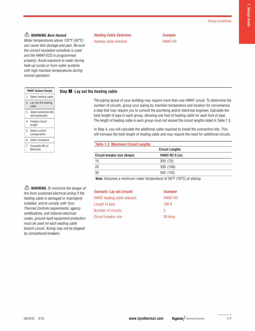
Step Lay out the heating cable
The piping layout of your building may require more than one HWAT circuit. To determine the number of circuits, group your piping by maintain temperature and location for convenience, a step that may require you to consult the plumbing and/or electrical engineer. Calculate the total length of pipe in each group, allowing one foot of heating cable for each foot of pipe. The length of heating cable in each group must not exceed the circuit lengths listed in Table 1.3.
In Step 4, you will calculate the additional cable required to install the connection kits. This will increase the total length of heating cable and may require the need for additional circuits.
Table 1.3 Maximum Circuit Lengths
Circuit Lengths
Circuit breaker size (Amps) HWAT-R2 ft (m)
15 250 (75)20 330 (100)30 500 (150)
Note: Assumes a minimum water temperature of 50°F (10°C) at startup
Example: Lay out circuits Example
HWAT heating cable selected HWAT-R2
Length of pipe 700 ft
Number of circuits 2
Circuit breaker size 30 Amp
WARNING Burn Hazard
Water temperatures above 120°F (50°C) can cause skin damage and pain. Be sure the correct insulation schedlule is used and the HWAT-ECO is programmed properly. Avoid exposure to water during heat-up cycles or from water systems with high maintain temperatures during normal operation.
WARNING To minimize the danger of fi re from sustained electrical arcing if the heating cable is damaged or improperly installed, and to comply with Tyco Thermal Controls requirements, agency certifi cations, and national electrical codes, ground-fault equipment protection must be used on each heating cable branch circuit. Arcing may not be stopped by conventional breakers.
SECTION 1: DESIGN GUIDE
1-8 www.tycothermal.com H57510 2/12
HWAT System Design
1. Select heating cable
6. Select insulation
2. Lay out the heating cable
3. Select connection kits and accessories
4. Finalize circuit length
5. Select control configuration
7. Complete Bill of Materials
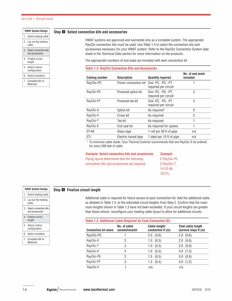
Step Select connection kits and accessories
HWAT systems are approved and warranted only as a complete system. The appropriate RayClic connection kits must be used. Use Table 1.4 to select the connection kits and accessories necessary for your HWAT system. Refer to the RayClic Connection System data sheet in the Technical Data section for more information on the products.
The appropriate numbers of end seals are included with each connection kit.
Table 1.4 RayClic Connection Kits and Accessories
Catalog number Description Quantity required
No. of end seals
included
RayClic-PC Power connection kit One -PC, -PS, -PT required per circuit
1
RayClic-PS Powered splice kit One -PC, -PS, -PT required per circuit
2
RayClic-PT Powered tee kit One -PC, -PS, -PT required per circuit
3
RayClic-S Splice kit As required* 0RayClic-X Cross kit As required 2RayClic-T Tee kit As required 1RayClic-E End seal kit As required for spares 1GT-66 Glass tape 1 roll per 50 ft of pipe n/aETL Electric traced tape 1 label per 10 ft of pipe n/a* To minimize cable waste, Tyco Thermal Controls recommends that one RayClic-S be ordered for every 500 feet of cable.
Example: Select connection kits and accessories Example
Piping layout determined that the following 2 RayClic-PCconnection kits and accessories are required. 2 RayClic-T 14 GT-66 70 ETL
HWAT System Design
1. Select heating cable
6. Select insulation
2. Lay out the heating cable
3. Select connection kits and accessories
4. Finalize circuit length
5. Select control configuration
7. Complete Bill of Materials
Step Finalize circuit length
Additional cable is required for future access at each connection kit. Add the additional cable, as detailed in Table 1.5, to the estimated circuit lengths from Step 2. Confi rm that the maxi-mum lengths shown in Table 1.3 have not been exceeded. If your circuit lengths are greater than those shown, reconfi gure your heating cable layout to allow for additional circuits.
Table 1.5 Additional Cable Required for Each Connection Kit
Connection kit name
No. of cable
connections/kit
Cable length/
connection ft (m)
Total cable length
(service loop) ft (m)
RayClic-PC 1 2.0 (0.6) 2.0 (0.6)RayClic-S 2 1.0 (0.3) 2.0 (0.6)RayClic-T 3 1.0 (0.3) 3.0 (0.9)RayClic-X 4 1.0 (0.3) 4.0 (1.2)RayClic-PS 2 1.5 (0.5) 3.0 (0.9)RayClic-PT 3 1.3 (0.4) 4.0 (1.2)RayClic-E 1 n/a n/a
H57510 2/12 www.tycothermal.com 1-9
Design Guidelines
1. D
esig
n G
uid
e
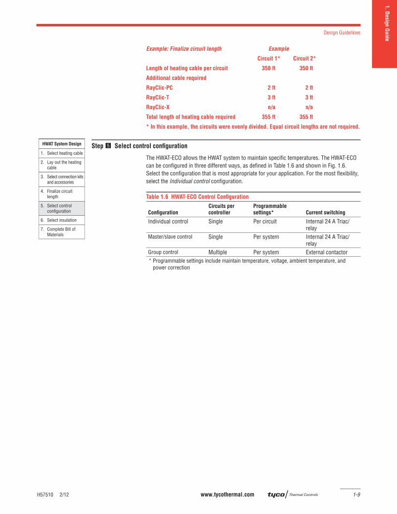
Example: Finalize circuit length Example
Circuit 1* Circuit 2*
Length of heating cable per circuit 350 ft 350 ft
Additional cable required
RayClic-PC 2 ft 2 ft
RayClic-T 3 ft 3 ft
RayClic-X n/a n/a
Total length of heating cable required 355 ft 355 ft
* In this example, the circuits were evenly divided. Equal circuit lengths are not required.
HWAT System Design
1. Select heating cable
6. Select insulation
2. Lay out the heating cable
3. Select connection kits and accessories
4. Finalize circuit length
5. Select control configuration
7. Complete Bill of Materials
Step Select control confi guration
The HWAT-ECO allows the HWAT system to maintain specifi c temperatures. The HWAT-ECO can be confi gured in three different ways, as defi ned in Table 1.6 and shown in Fig. 1.6. Select the confi guration that is most appropriate for your application. For the most fl exibility, select the Individual control confi guration.
Table 1.6 HWAT-ECO Control Confi guration
Confi guration
Circuits per
controller
Programmable
settings* Current switching
Individual control Single Per circuit Internal 24 A Triac/relay
Master/slave control Single Per system Internal 24 A Triac/relay
Group control Multiple Per system External contactor* Programmable settings include maintain temperature, voltage, ambient temperature, and power correction
SECTION 1: DESIGN GUIDE
1-10 www.tycothermal.com H57510 2/12
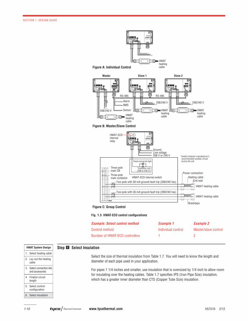
Fig. 1.5 HWAT-ECO control confi gurations
Example: Select control method Example 1 Example 2
Control method Individual control Master/slave control
Number of HWAT-ECO controllers 1 2
HWAT System Design
1. Select heating cable
6. Select insulation
2. Lay out the heating cable
3. Select connection kits and accessories
4. Finalize circuit length
5. Select control configuration
Step Select Insulation
Select the size of thermal insulation from Table 1.7. You will need to know the length and diameter of each pipe used in your application.
For pipes 1 1/4 inches and smaller, use insulation that is oversized by 1/4 inch to allow room for insulating over the heating cables. Table 1.7 specifi es IPS (Iron Pipe Size) insulation, which has a greater inner diameter than CTS (Copper Tube Size) insulation.
Nø1
HWAT-ECO internal switch
ø3ø2
HWAT heating cable
HWAT heating cable
Braid/pipe
Two-pole with 30-mA ground-fault trip (208/240 Vac)
Two-pole with 30-mA ground-fault trip (208/240 Vac)
Three-polemain CB
HWAT-ECOinternalrelay
Power connection
Panel energized light
*Contactor coil(208 or 240 V)
Heating cableEnd seal
Three-polemain contactor
Figure A: Individual Control
Figure B: Master/Slave Control
Figure C: Group Control
HWATheatingcableHWAT
heatingcable
HWATheatingcable
HWATheatingcable
208/240 V208/240 V
208/240 V
RS-485RS-485
AlarmBMS
Sensor
GroundLine voltage208 V or 240 V
Slave 2Slave 1Master
Install contactor manufacturer’s recommended snubber circuit across the coil
*
H57510 2/12 www.tycothermal.com 1-11
Design Guidelines
1. D
esig
n G
uid
e
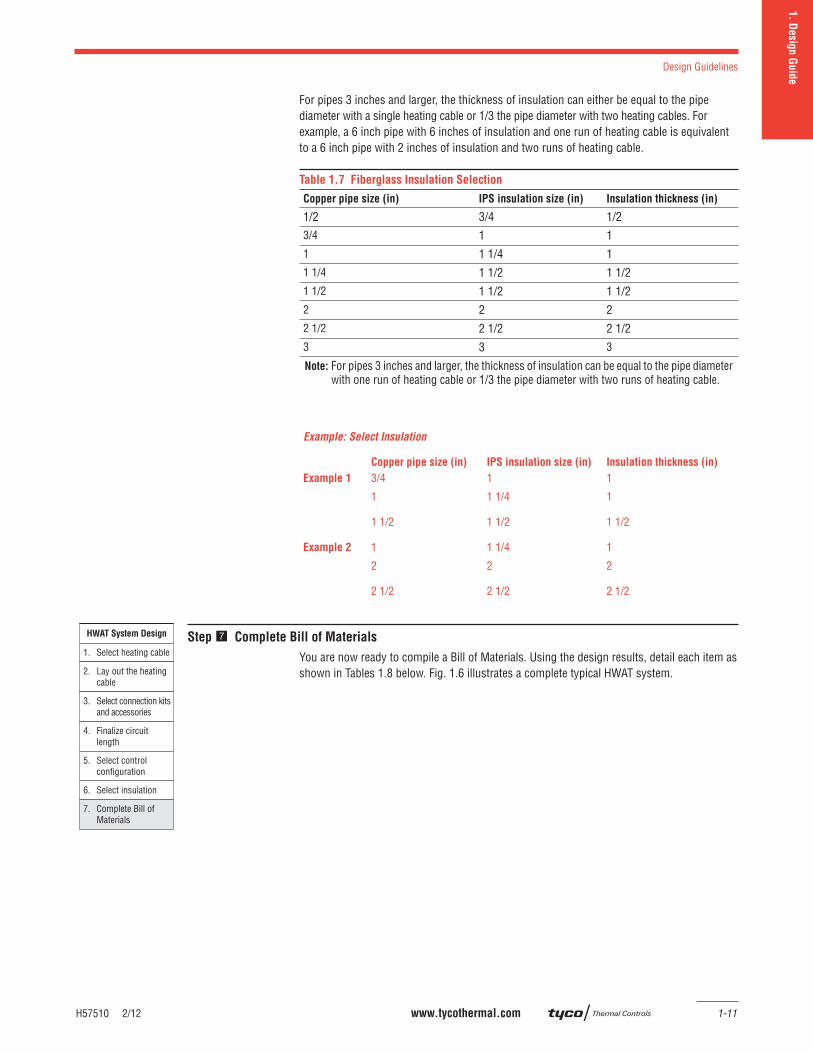
For pipes 3 inches and larger, the thickness of insulation can either be equal to the pipe diameter with a single heating cable or 1/3 the pipe diameter with two heating cables. For example, a 6 inch pipe with 6 inches of insulation and one run of heating cable is equivalent to a 6 inch pipe with 2 inches of insulation and two runs of heating cable.
Table 1.7 Fiberglass Insulation Selection
Copper pipe size (in) IPS insulation size (in) Insulation thickness (in)
1/2 3/4 1/23/4 1 11 1 1/4 11 1/4 1 1/2 1 1/21 1/2 1 1/2 1 1/22 2 22 1/2 2 1/2 2 1/23 3 3
Note: For pipes 3 inches and larger, the thickness of insulation can be equal to the pipe diameter with one run of heating cable or 1/3 the pipe diameter with two runs of heating cable.
Example: Select Insulation
Copper pipe size (in) IPS insulation size (in) Insulation thickness (in)
Example 1 3/4 1 1
1 1 1/4 1
1 1/2 1 1/2 1 1/2
Example 2 1 1 1/4 1
2 2 2
2 1/2 2 1/2 2 1/2
HWAT System Design
1. Select heating cable
6. Select insulation
2. Lay out the heating cable
3. Select connection kits and accessories
4. Finalize circuit length
5. Select control configuration
7. Complete Bill of Materials
Step Complete Bill of Materials
You are now ready to compile a Bill of Materials. Using the design results, detail each item as shown in Tables 1.8 below. Fig. 1.6 illustrates a complete typical HWAT system.
SECTION 1: DESIGN GUIDE
1-12 www.tycothermal.com H57510 2/12
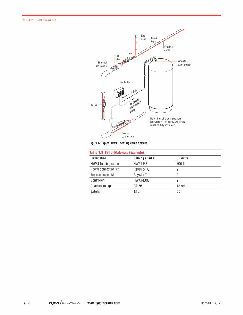
Fig. 1.6 Typical HWAT heating cable system
Table 1.8 Bill of Materials (Example)
Description Catalog number Quantity
HWAT heating cable HWAT-R2 706 ftPower connection kit RayClic-PC 2Tee connection kit RayClic-T 2Controller HWAT-ECO 2Attachment tape GT-66 12 rollsLabels ETL 70
Splice To power
distributio
n
panel
Note: Partial pipe insulationshown here for clarity. All pipesmust be fully insulated.
End seal
Tee
Thermalinsulation
Heatingcable
Hot waterheater sensor
Glasstape
Powerconnection
Controller
To BMS
ETLlabel
1.
Desig
n G
uid
e2. D
esig
n N
ote
s3.
Desig
n E
xam
ple
s4.
Tech
nica
l Data
sheets
5.
Exp
anded C
apabilitie
s6.
Specifi ca
tion
7.
Warra
nty
H58029 2/12 www.tycothermal.com 2-1
Section 2.1:
Hot Water Temperature
Maintenance System: Insulation
Schedule of Non-static Supply piping
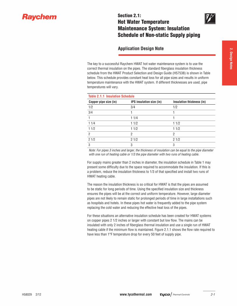
The key to a successful Raychem HWAT hot water maintenance system is to use the correct thermal insulation on the pipes. The standard fi berglass insulation thickness schedule from the HWAT Product Selection and Design Guide (H57538) is shown in Table below. This schedule provides constant heat loss for all pipe sizes and results in uniform temperature maintenance with the HWAT system. If different thicknesses are used, pipe temperatures will vary.
Table 2.1.1 Insulation Schedule
Copper pipe size (in) IPS insulation size (in) Insulation thickness (in)
1/2 3/4 1/23/4 1 11 1 1/4 11 1/4 1 1/2 1 1/21 1/2 1 1/2 1 1/22 2 22 1/2 2 1/2 2 1/23 3 3
Note: For pipes 3 inches and larger, the thickness of insulation can be equal to the pipe diameter with one run of heating cable or 1/3 the pipe diameter with two runs of heating cable.
For supply mains greater than 2 inches in diameter, the insulation schedule in Table 1 may present some diffi culty due to the space required to accommodate the insulation. If this is a problem, reduce the insulation thickness to 1/3 of that specifi ed and install two runs of HWAT heating cable.
The reason the insulation thickness is so critical for HWAT is that the pipes are assumed to be static for long periods of time. Using the specifi ed insulation size and thickness ensures the pipes will be at the correct and uniform temperature. However, large diameter pipes are not likely to remain static for prolonged periods of time in large installations such as hospitals and hotels. In these pipes hot water is frequently added to the pipe system replacing the cold water and reducing the effective heat loss of the pipes.
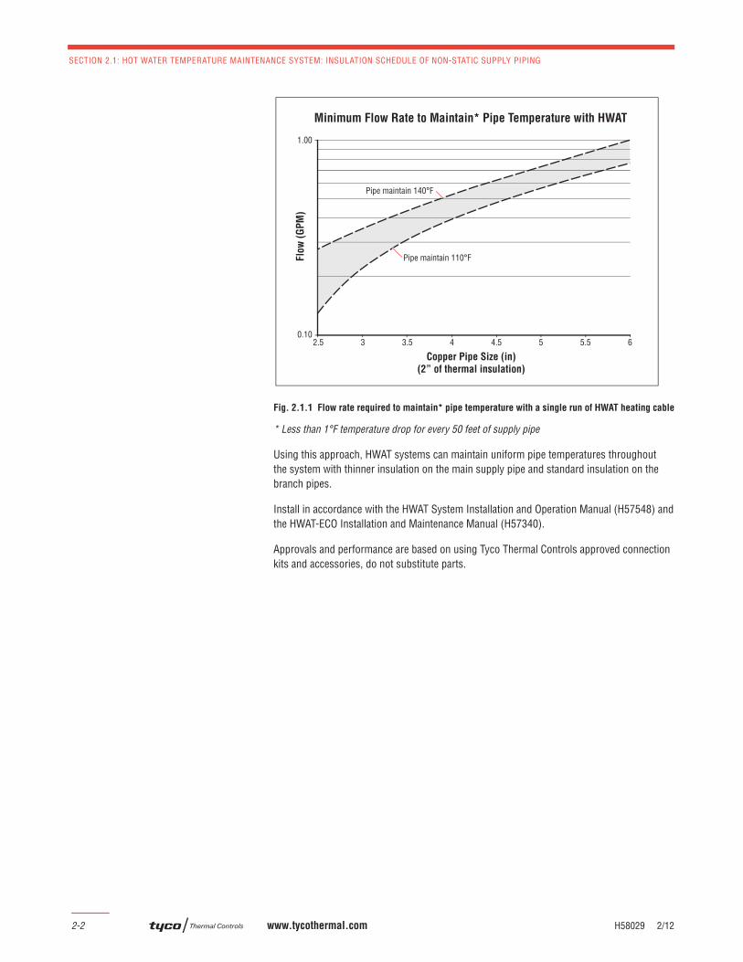
For these situations an alternative insulation schedule has been created for HWAT systems on copper pipes 2 1/2 inches or larger with constant but low fl ow. The mains can be insulated with only 2 inches of fi berglass thermal insulation and use a single run of HWAT heating cable if the minimum fl ow is maintained. Figure 2.1.1 shows the fl ow rate required to have less than 1°F temperature drop for every 50 feet of supply pipe.
Application Design Note
SECTION 2.1: HOT WATER TEMPERATURE MAINTENANCE SYSTEM: INSULATION SCHEDULE OF NON-STATIC SUPPLY PIPING
2-2 www.tycothermal.com H58029 2/12
Fig. 2.1.1 Flow rate required to maintain* pipe temperature with a single run of HWAT heating cable
* Less than 1°F temperature drop for every 50 feet of supply pipe
Using this approach, HWAT systems can maintain uniform pipe temperatures throughout the system with thinner insulation on the main supply pipe and standard insulation on the branch pipes.
Install in accordance with the HWAT System Installation and Operation Manual (H57548) and the HWAT-ECO Installation and Maintenance Manual (H57340).
Approvals and performance are based on using Tyco Thermal Controls approved connection kits and accessories, do not substitute parts.
Minimum Flow Rate to Maintain* Pipe Temperature with HWAT
Pipe maintain 110°F
Pipe maintain 140°F
Flo
w (
GP
M)
Copper Pipe Size (in)
(2” of thermal insulation)
0.10
1.00
2.5 3 3.5 4 4.5 5 5.5 6
1.
Desig
n G
uid
e3.
Desig
n E
xam
ple
s4.
Tech
nica
l Data
sheets
5.
Exp
anded C
apabilitie
s6.
Specifi ca
tion
7.
Warra
nty
H58028 2/12 www.tycothermal.com 2-3
2. D
esig
n N
ote
s
Section 2.2:
Hybrid Hot Water Temperature
Maintenance System:
A combination of Recirculation
and HWAT Designs
In high rise residential construction, it is fairly common for the plumbing engineer to recirculate the hot water main but not the branch piping. This is done to minimize the wait for hot water at the point of use in the condominium. The water in the main stays hot, but because the hot water line serving the condominium is typically not recirculated, the water temperature in the branch piping goes to ambient when there is no hot water fl ow. These horizontal distribution lines are diffi cult to recirculate because of pressure and balancing in the high rise building. Furthermore, the risers don’t always line up vertically because the fl oor plan of each unit may be different. Home owners are therefore required to run showers or sinks for long periods of time to draw new hot water into the unit, which is a signifi cant waste of water.
The Raychem HWAT hot water maintenance system offers a solution utilizing self-regulating heating cables and the HWAT-ECO or ACCS-30 electronic controller, in conjunction with the recirculation system. This combination of recirculated hot water mains and the HWAT system for the horizontal piping is the best of both worlds. The engineer can simply heat trace the horizontal hot water lines within the condominium to provide the owner with instant hot water. Different fl oor plans are also not a problem because the HWAT heating cable simply attaches to the hot water piping regardless of the confi guration.
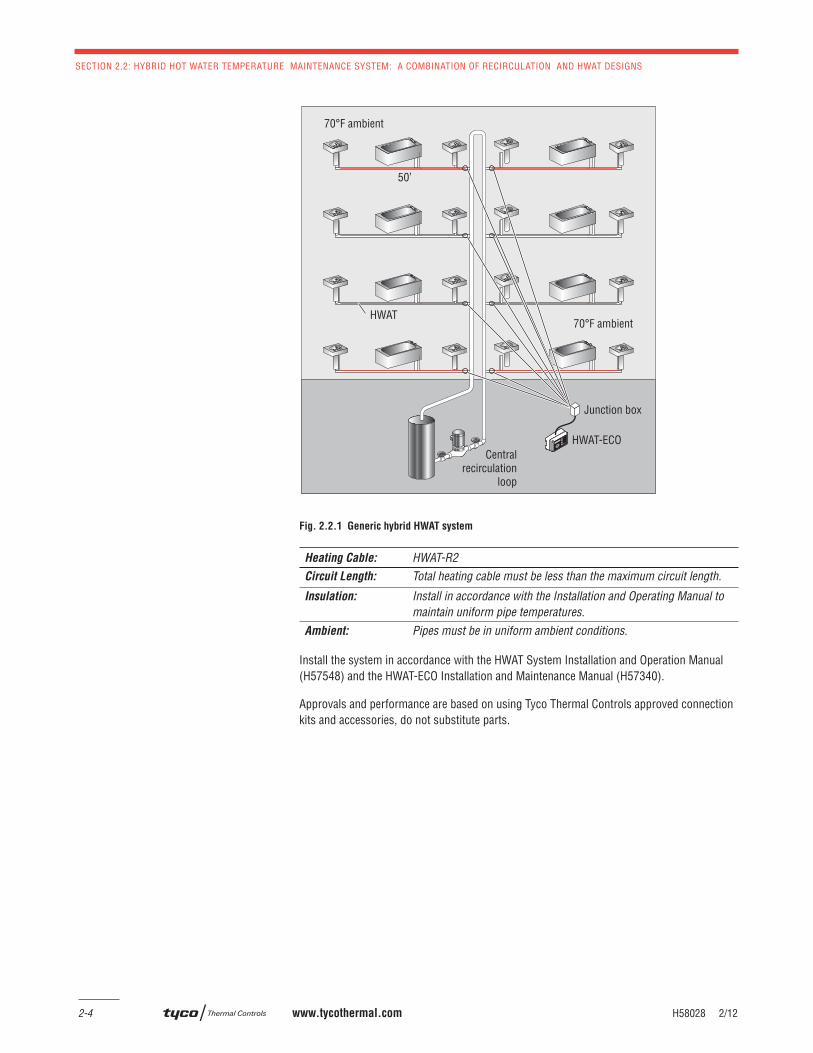
The drawing in Figure 1 shows a typical hot water riser with recirculation and heat traced horizontal hot water lines feeding the condominiums. The HWAT system is installed following the design guidelines in the HWAT System Installation and Operation Manual (H57548).
Multiple horizontal runs can be controlled as long as the HWAT heating cable maximum circuit length is not exceeded, the same cable is on each run and the ambient conditions are the same for each pipe. The system shown in Figure 1 includes eight circuits of HWAT-R2 heating cable each 50 feet long, which can be wired in parallel to a junction box and controlled by a single HWAT-ECO controller.
Application Design Note
SECTION 2.2: HYBRID HOT WATER TEMPERATURE MAINTENANCE SYSTEM: A COMBINATION OF RECIRCULATION AND HWAT DESIGNS
2-4 www.tycothermal.com H58028 2/12
Fig. 2.2.1 Generic hybrid HWAT system
Heating Cable: HWAT-R2Circuit Length: Total heating cable must be less than the maximum circuit length.
Insulation: Install in accordance with the Installation and Operating Manual to maintain uniform pipe temperatures.
Ambient: Pipes must be in uniform ambient conditions.
Install the system in accordance with the HWAT System Installation and Operation Manual (H57548) and the HWAT-ECO Installation and Maintenance Manual (H57340).
Approvals and performance are based on using Tyco Thermal Controls approved connection kits and accessories, do not substitute parts.
Centralrecirculation
loop
70°F ambient
70°F ambient
50’
HWAT-ECO
Junction box
HWAT
1.
Desig
n G
uid
e3.
Desig
n E
xam
ple
s4.
Tech
nica
l Data
sheets
5.
Exp
anded C
apabilitie
s6.
Specifi ca
tion
7.
Warra
nty
H58094 2/12 www.tycothermal.com 2-5
2. D
esig
n N
ote
s
Section 2.3:
HWAT on Plastic Hot Water
Distribution Piping
The Raychem HWAT hot water maintenance system incorporates HWAT-R2 heating cable, the Raychem HWAT-ECO or ACCS-30 controller, or the DigiTrace ACCS-30 multi-point controller. These controllers can adjust the power output of the HWAT heating cables to compensate for the poor heat transfer of plastic pipes, and maintain the correct water temperature.
Due to the increasing cost of copper, and in regions where pipe corrosion is a concern, plastic pipes are becoming more common in hot water distributions systems. Plastic pipes approved for use with HWAT heating cables include CPVC, rigid PEX and PEX tubing (fi xed in place and supported no greater than every 32 inches along its length). HWAT should not be installed on un-supported PEX or nylon tubing due to the fact that frequent fl exing could reduce the power output of the cable.
Use the following guidelines to install and operate HWAT heating cable on approved plastic pipe:
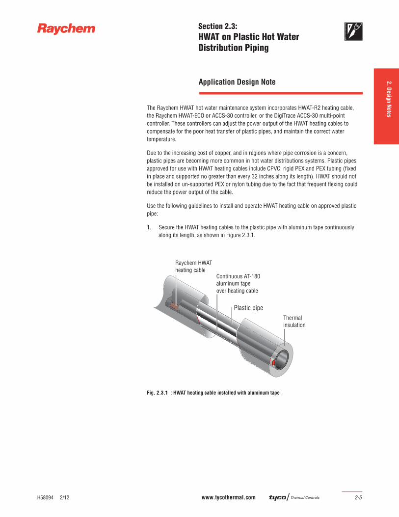
1. Secure the HWAT heating cables to the plastic pipe with aluminum tape continuously along its length, as shown in Figure 2.3.1.
Fig. 2.3.1 : HWAT heating cable installed with aluminum tape
Plastic pipe
Application Design Note
SECTION 2.3: HWAT ON PLASTIC HOT WATER DISTRIBUTION PIPING
2-6 www.tycothermal.com H58094 2/12
1. To maintain desired water temperature on approved plastic pipes, adjust the temperature controllers as follows:
a. HWAT-ECO:Set the “Power Correction Factor” in the HWAT-ECO menu to the values shown in Table 2.3.1.
Heating Cable Power Correction Factor
HWAT-R2 1.25
Table 2.3.1: Plastic pipe power correction factors
b. ACCS-30 controller:Select “Plastic Pipe” in the HWAT circuit set up menu. This setting automatically applies the same “Power Correction Factors” shown in Table 2.3.1.
1.
Desig
n G
uid
e2.
Desig
n N
ote
s3. D
esig
n E
xam
ple
s4.
Tech
nica
l Data
sheets
5.
Exp
anded C
apabilitie
s6.
Specifi ca
tion
7.
Warra
nty
H58498 2/12 www.tycothermal.com 3-1
Section 3:
Design Examples
School
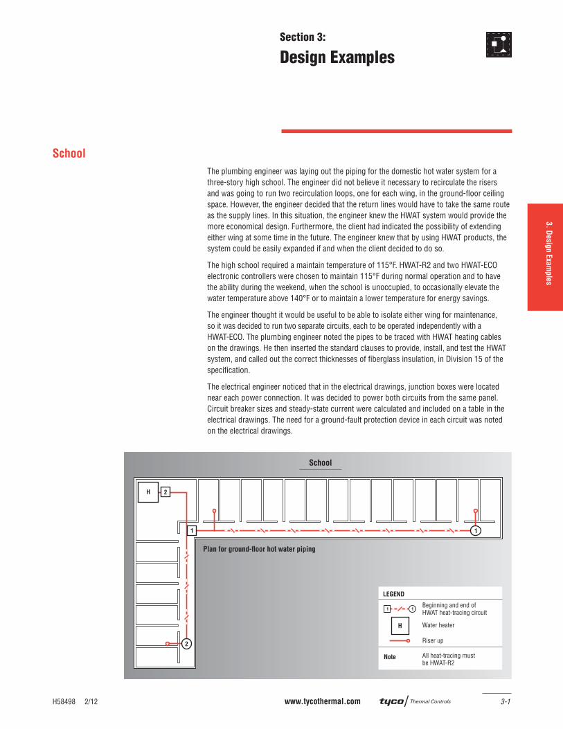
The plumbing engineer was laying out the piping for the domestic hot water system for a three-story high school. The engineer did not believe it necessary to recirculate the risers and was going to run two recirculation loops, one for each wing, in the ground-fl oor ceiling space. However, the engineer decided that the return lines would have to take the same route as the supply lines. In this situation, the engineer knew the HWAT system would provide the more economical design. Furthermore, the client had indicated the possibility of extending either wing at some time in the future. The engineer knew that by using HWAT products, the system could be easily expanded if and when the client decided to do so.
The high school required a maintain temperature of 115°F. HWAT-R2 and two HWAT-ECO electronic controllers were chosen to maintain 115°F during normal operation and to have the ability during the weekend, when the school is unoccupied, to occasionally elevate the water temperature above 140°F or to maintain a lower temperature for energy savings.
The engineer thought it would be useful to be able to isolate either wing for maintenance, so it was decided to run two separate circuits, each to be operated independently with a HWAT-ECO. The plumbing engineer noted the pipes to be traced with HWAT heating cables on the drawings. He then inserted the standard clauses to provide, install, and test the HWAT system, and called out the correct thicknesses of fi berglass insulation, in Division 15 of the specifi cation.
The electrical engineer noticed that in the electrical drawings, junction boxes were located near each power connection. It was decided to power both circuits from the same panel. Circuit breaker sizes and steady-state current were calculated and included on a table in the electrical drawings. The need for a ground-fault protection device in each circuit was noted on the electrical drawings.
Plan for ground-floor hot water piping
School
Water heater
Riser up
Beginning and end of HWAT heat-tracing circuit
Note All heat-tracing must be HWAT-R2
LEGEND
SECTION 3: DESIGN EXAMPLES
3-2 www.tycothermal.com H58498 2/12
Prison
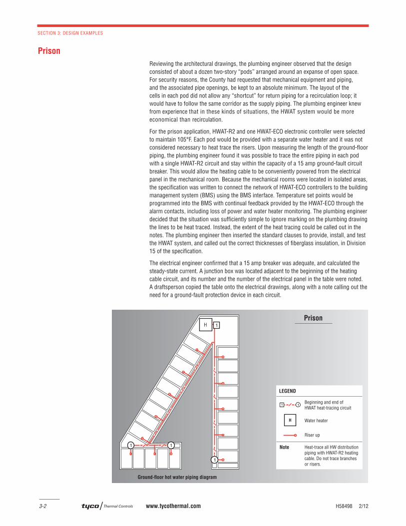
Reviewing the architectural drawings, the plumbing engineer observed that the design consisted of about a dozen two-story “pods” arranged around an expanse of open space. For security reasons, the County had requested that mechanical equipment and piping, and the associated pipe openings, be kept to an absolute minimum. The layout of the cells in each pod did not allow any “shortcut” for return piping for a recirculation loop; it would have to follow the same corridor as the supply piping. The plumbing engineer knew from experience that in these kinds of situations, the HWAT system would be more economical than recirculation.
For the prison application, HWAT-R2 and one HWAT-ECO electronic controller were selected to maintain 105°F. Each pod would be provided with a separate water heater and it was not considered necessary to heat trace the risers. Upon measuring the length of the ground-fl oor piping, the plumbing engineer found it was possible to trace the entire piping in each pod with a single HWAT-R2 circuit and stay within the capacity of a 15 amp ground-fault circuit breaker. This would allow the heating cable to be conveniently powered from the electrical panel in the mechanical room. Because the mechanical rooms were located in isolated areas, the specifi cation was written to connect the network of HWAT-ECO controllers to the building management system (BMS) using the BMS interface. Temperature set points would be programmed into the BMS with continual feedback provided by the HWAT-ECO through the alarm contacts, including loss of power and water heater monitoring. The plumbing engineer decided that the situation was suffi ciently simple to ignore marking on the plumbing drawing the lines to be heat traced. Instead, the extent of the heat tracing could be called out in the notes. The plumbing engineer then inserted the standard clauses to provide, install, and test the HWAT system, and called out the correct thicknesses of fi berglass insulation, in Division 15 of the specifi cation.
The electrical engineer confi rmed that a 15 amp breaker was adequate, and calculated the steady-state current. A junction box was located adjacent to the beginning of the heating cable circuit, and its number and the number of the electrical panel in the table were noted. A draftsperson copied the table onto the electrical drawings, along with a note calling out the need for a ground-fault protection device in each circuit.
HPrison
Ground-floor hot water piping diagram
Water heater
Riser up
Beginning and end of HWAT heat-tracing circuit
Note Heat-trace all HW distribution piping with HWAT-R2 heating cable. Do not trace branches or risers.
LEGEND
H58498 2/12 www.tycothermal.com 3-3
Apartment Building
1.
Desig
n G
uid
e2.
Desig
n N
ote
s4.
Tech
nica
l Data
sheets
5.
Exp
ande
d C
apabilitie
s6.
Specifi ca
tion
7.
Warra
nty
3. D
esig
n E
xam
ple
s
Apartment Building
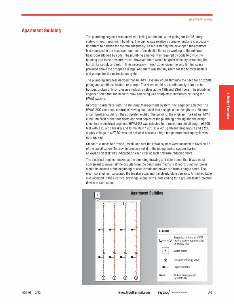
The plumbing engineer was faced with laying out the hot water piping for the 35-story state-of-the-art apartment building. The piping was relatively complex, making it especially important to balance the system adequately. As requested by the developer, the architect had squeezed in the maximum number of residential fl oors by working to the minimum headroom allowed by code. The plumbing engineer was required by code to divide the building into three pressure zones. However, there would be great diffi culty in running the horizontal supply and return lines necessary in each zone, given the very limited space provided above the dropped ceilings. And there was not any room for the booster heaters and pumps for the recirculation system.
The plumbing engineer decided that an HWAT system would eliminate the need for horizontal piping and additional heaters or pumps. The risers could run continuously from top to bottom, broken only by pressure reducing valves at the 11th and 23rd fl oors. The plumbing engineer noted that the need for fl ow balancing was completely eliminated by using the HWAT system.
In order to interface with the Building Management System, the engineer selected the HWAT-ECO electronic controller. Having estimated that a single circuit length on a 20 amp circuit breaker could run the complete height of the building, the engineer marked an HWAT circuit on each of the four risers and sent copies of the plumbing drawing and the design sheet to the electrical engineer. HWAT-R2 was selected for a maximum circuit length of 500 feet with a 20 amp breaker and to maintain 120°F at a 70°F ambient temperature and a 208 supply voltage. HWAT-R2 was not selected because a high temperature heat-up cycle was not required.
Standard clauses to provide, install, and test the HWAT system were included in Division 15 of the specifi cation. To provide pressure relief in the piping during system startup, an expansion tank was indicated on each riser at each pressure reducing valve.
The electrical engineer looked at the plumbing drawing and determined that it was most convenient to power all the circuits from the penthouse mechanical room. Junction boxes would be located at the beginning of each circuit and power run from a single panel. The electrical engineer calculated the breaker sizes and the steady-state currents. A fi nished table was included in the electrical drawings, along with a note calling for a ground-fault protection device in each circuit.
Pressure-reducing valve
Expansion tank
Beginning and end of HWAT heating cable circuit installed on supply pipe
Apartment Building
Water heater
Note All heat-tracing must be HWAT-R2
LEGEND
SECTION 3: DESIGN EXAMPLES
3-4 www.tycothermal.com H58498 2/12
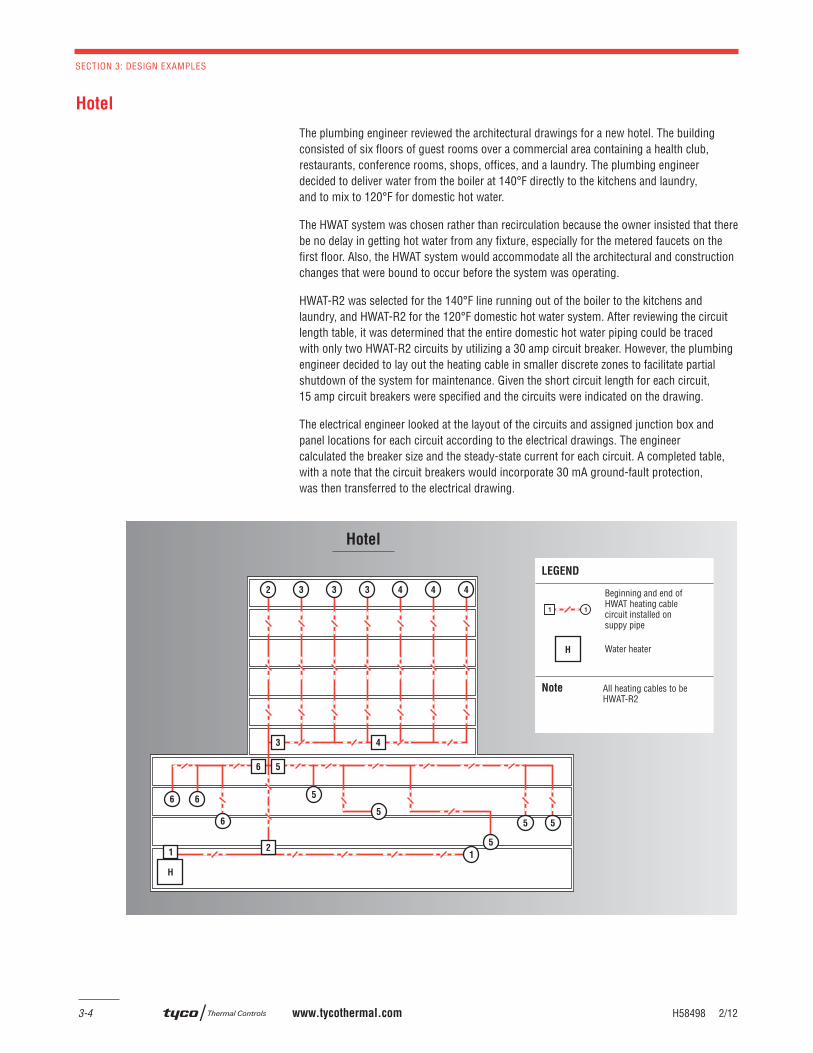
Hotel
The plumbing engineer reviewed the architectural drawings for a new hotel. The building consisted of six fl oors of guest rooms over a commercial area containing a health club, restaurants, conference rooms, shops, offi ces, and a laundry. The plumbing engineer decided to deliver water from the boiler at 140°F directly to the kitchens and laundry, and to mix to 120°F for domestic hot water.
The HWAT system was chosen rather than recirculation because the owner insisted that there be no delay in getting hot water from any fi xture, especially for the metered faucets on the fi rst fl oor. Also, the HWAT system would accommodate all the architectural and construction changes that were bound to occur before the system was operating.
HWAT-R2 was selected for the 140°F line running out of the boiler to the kitchens and laundry, and HWAT-R2 for the 120°F domestic hot water system. After reviewing the circuit length table, it was determined that the entire domestic hot water piping could be traced with only two HWAT-R2 circuits by utilizing a 30 amp circuit breaker. However, the plumbing engineer decided to lay out the heating cable in smaller discrete zones to facilitate partial shutdown of the system for maintenance. Given the short circuit length for each circuit, 15 amp circuit breakers were specifi ed and the circuits were indicated on the drawing.
The electrical engineer looked at the layout of the circuits and assigned junction box and panel locations for each circuit according to the electrical drawings. The engineer calculated the breaker size and the steady-state current for each circuit. A completed table, with a note that the circuit breakers would incorporate 30 mA ground-fault protection, was then transferred to the electrical drawing.
Hotel
LEGEND
Water heater
Beginning and end of HWAT heating cable circuit installed on suppy pipe
Note All heating cables to be HWAT-R2
H57512 2/12 www.tycothermal.com 4-1
1.
Desig
n G
uid
e2.
Desig
n N
ote
s3.
Desig
n E
xam
ple
s4. Te
chnica
l Data
Sheets
5.
Exp
anded C
apabilitie
s6.
Specifi ca
tion
7.
Warra
nty
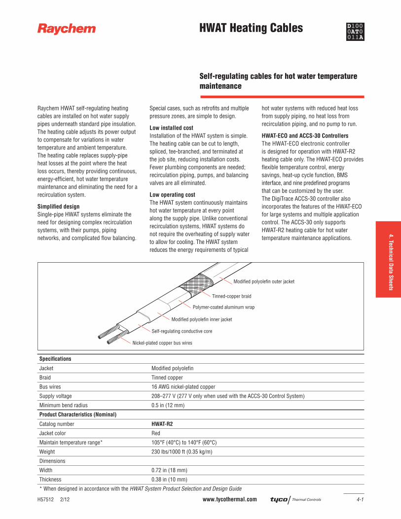
HWAT Heating Cables
Raychem HWAT self-regulating heating cables are installed on hot water supply pipes underneath standard pipe insulation. The heating cable adjusts its power output to compensate for variations in water temperature and ambient temperature. The heating cable replaces supply-pipe heat losses at the point where the heat loss occurs, thereby providing continuous, energy-effi cient, hot water temperature maintenance and eliminating the need for a recirculation system.
Simplifi ed design
Single-pipe HWAT systems eliminate the need for designing complex recirculation systems, with their pumps, piping networks, and complicated fl ow balancing.
Special cases, such as retrofi ts and multiple pressure zones, are simple to design.
Low installed cost
Installation of the HWAT system is simple. The heating cable can be cut to length, spliced, tee-branched, and terminated at the job site, reducing installation costs. Fewer plumbing components are needed; recirculation piping, pumps, and balancing valves are all eliminated.
Low operating cost
The HWAT system continuously maintains hot water temperature at every point along the supply pipe. Unlike conventional recirculation systems, HWAT systems do not require the overheating of supply water to allow for cooling. The HWAT system reduces the energy requirements of typical
hot water systems with reduced heat loss from supply piping, no heat loss from recirculation piping, and no pump to run.
HWAT-ECO and ACCS-30 Controllers
The HWAT-ECO electronic controller is designed for operation with HWAT-R2 heating cable only. The HWAT-ECO provides fl exible temperature control, energy savings, heat-up cycle function, BMS interface, and nine predefi ned programs that can be customized by the user. The DigiTrace ACCS-30 controller also incorporates the features of the HWAT-ECO for large systems and multiple application control. The ACCS-30 only supports HWAT-R2 heating cable for hot water temperature maintenance applications.
Nickel-plated copper bus wires
Self-regulating conductive core
Polymer-coated aluminum wrap
Tinned-copper braid
Modified polyolefin outer jacket
Modified polyolefin inner jacket
Specifi cations
Jacket Modifi ed polyolefi n
Braid Tinned copper
Bus wires 16 AWG nickel-plated copper
Supply voltage 208–277 V (277 V only when used with the ACCS-30 Control System)
Minimum bend radius 0.5 in (12 mm)
Product Characteristics (Nominal)
Catalog number HWAT-R2
Jacket color Red
Maintain temperature range* 105°F (40°C) to 140°F (60°C)
Weight 230 lbs/1000 ft (0.35 kg/m)
Dimensions
Width 0.72 in (18 mm)
Thickness 0.38 in (10 mm)
* When designed in accordance with the HWAT System Product Selection and Design Guide
Self-regulating cables for hot water temperature
maintenance
HWAT Heating Cables
4-2 www.tycothermal.com H57512 2/12
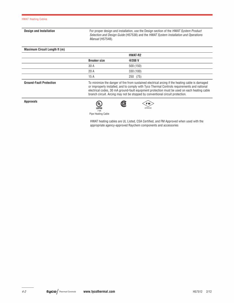
Design and Installation For proper design and installation, use the Design section of the HWAT System ProductSelection and Design Guide (H57538) and the HWAT System Installation and Operations Manual (H57548).
Maximum Circuit Length ft (m)
HWAT-R2
Breaker size @208 V
30 A 500 (150)
20 A 330 (100)
15 A 250 (75)
Ground-Fault Protection To minimize the danger of fi re from sustained electrical arcing if the heating cable is damaged or improperly installed, and to comply with Tyco Thermal Controls requirements and national electrical codes, 30 mA ground-fault equipment protection must be used on each heating cable branch circuit. Arcing may not be stopped by conventional circuit protection.
Approvals
Pipe Heating Cable718K
HWAT heating cables are UL Listed, CSA Certified, and FM Approved when used with the appropriate agency-approved Raychem components and accessories
H57339 2/12 www.tycothermal.com 4-3
1.
Desig
n G
uid
e2.
Desig
n N
ote
s3.
Desig
n E
xam
ple
s5.
Exp
ande
d C
apabilitie
s6.
Specifi ca
tion
7.
Warra
nty
4. Te
chnica
l Data
Sheets
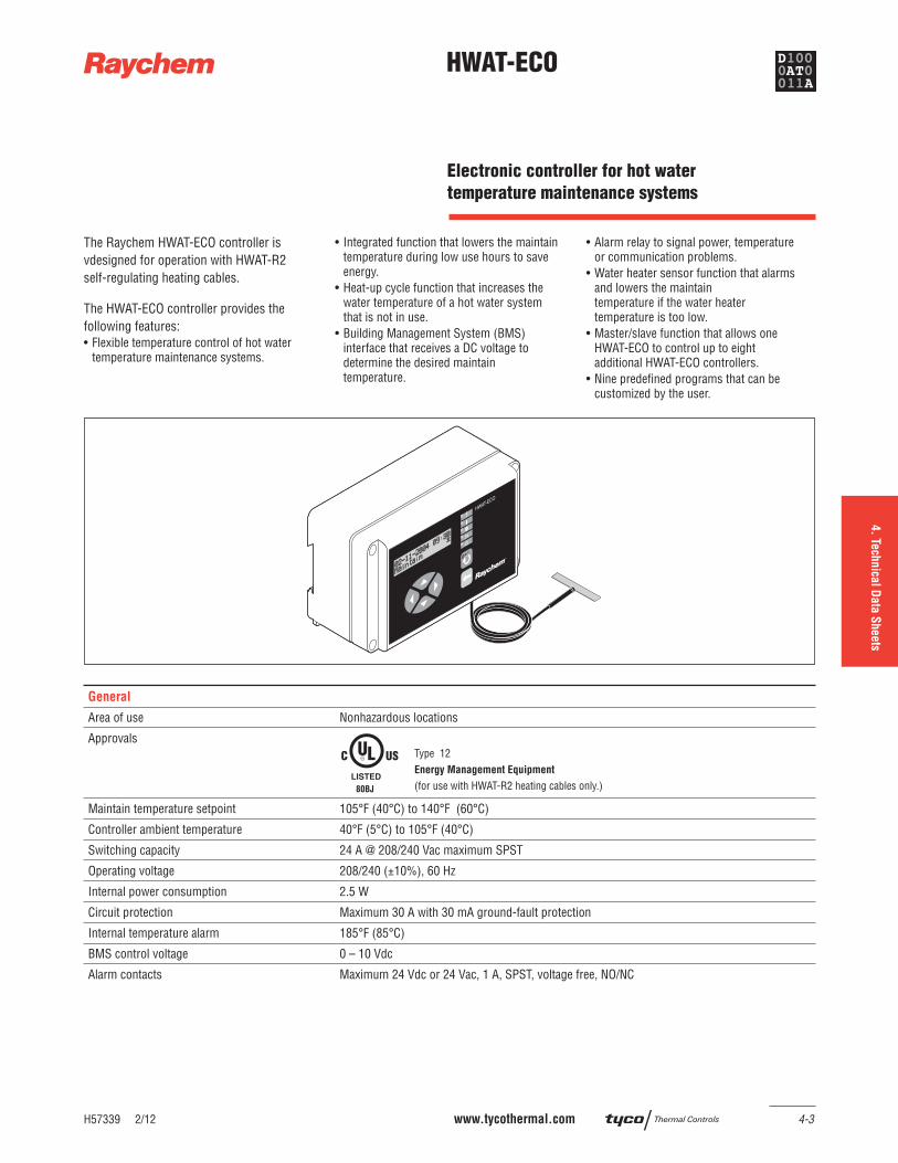
HWAT-ECO
The Raychem HWAT-ECO controller is vdesigned for operation with HWAT-R2 self-regulating heating cables.
The HWAT-ECO controller provides the following features:• Flexible temperature control of hot water
temperature maintenance systems.
• Integrated function that lowers the maintain temperature during low use hours to save energy.
• Heat-up cycle function that increases the water temperature of a hot water systemthat is not in use.
• Building Management System (BMS) interface that receives a DC voltage to determine the desired maintain temperature.
• Alarm relay to signal power, temperatureor communication problems.
• Water heater sensor function that alarms and lowers the maintain temperature if the water heater temperature is too low.
• Master/slave function that allows one HWAT-ECO to control up to eight additional HWAT-ECO controllers.
• Nine predefi ned programs that can be customized by the user.
General
Area of use Nonhazardous locations
Approvals
80BJ
Type 12Energy Management Equipment
(for use with HWAT-R2 heating cables only.)
Maintain temperature setpoint 105°F (40°C) to 140°F (60°C)
Controller ambient temperature 40°F (5°C) to 105°F (40°C)
Switching capacity 24 A @ 208/240 Vac maximum SPST
Operating voltage 208/240 (±10%), 60 Hz
Internal power consumption 2.5 W
Circuit protection Maximum 30 A with 30 mA ground-fault protection
Internal temperature alarm 185°F (85°C)
BMS control voltage 0 – 10 Vdc
Alarm contacts Maximum 24 Vdc or 24 Vac, 1 A, SPST, voltage free, NO/NC
Electronic controller for hot water
temperature maintenance systems
HWAT-ECO
4-4 www.tycothermal.com H57339 2/12
General
Alarm events • Loss of power• Controller reinitialized• Internal controller temperature too high• Water heater temperature too high• Water heater temperature too low• Master/slave error
Power correction factor To increase or decrease your actual pipe maintain temperature or adjust for hot water systems with rigid plastic pipes
Water heater sensor Thermistor with 13 ft 3 in (4 m) lead. A PT100 RTD may optionally be used.
Electromagnetic Compatibility (EMC) Complies to EN 50081-1/2 for emission and EN 50082-1/2 for immunity
Real time clock Leap year correction
Clock accuracy ±10 minutes per year
Enclosure
Enclosure rating NEMA 12 (IP54) – indoor use only
Enclosure material ABS
Mounting Wall mount with two screws or optional DIN rail
Conduit entries Two each – 1/2 in conduit entries
Cable gland 3-hole grommetMaximum cable size: • 2-wire: 20 AWG (0.5 mm²)• 4-wire: 24 AWG (0.2 mm²)
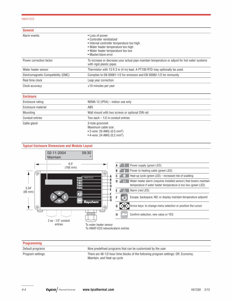
Typical Enclosure Dimensions and Module Layout
Power supply (green LED)
Power to heating cable (green LED)
Heat-up cycle (green LED) – increased risk of scalding
Water heater alarm (requires installed sensor) that lowers maintain temperature if water heater temperature is too low (green LED)
Alarm (red LED)
Escape, backspace; NO; or display maintain temperature setpoint
Arrow keys: to change menu selection or position the cursor
Confirm selection, new value or YES
A
B
C
D
E
F
G
H
6.5"(165 mm)
2 ea - 1/2" conduitentries To water heater sensor
To HWAT-ECO network/alarm entries
3.34"(85 mm)
02-11-2004 09:30Maintain *
A
BCD
E
FGH
Programming
Default programs Nine predefi ned programs that can be customized by the user
Program settings There are 48 1/2-hour time blocks of the following program settings: Off, Economy, Maintain, and Heat-up cycle
HWAT-ECO
H57339 2/12 www.tycothermal.com 4-5
1.
Desig
n G
uid
e2.
Desig
n N
ote
s3.
Desig
n E
xam
ple
s5.
Exp
ande
d C
apabilitie
s6.
Specifi ca
tion
7.
Warra
nty
4. Te
chnica
l Data
Sheets
Networking
Master/slave Master is selectable in the controller, up to eight slaves can be connected
Master/slave cable 2-wire, 300 V, minimum 24 AWG twisted pair
Memory
Parameters stored in memory All parameters are stored in nonvolatile memory, except date and time
Clock back-up time 1 year with lithium battery model 2025
Ground-Fault Protection
To minimize the danger of fi re from sustained electrical arcing if the heating cable is damaged or improperly installed, and to comply with the requirements of approval agencies, Tyco Thermal Controls and national and local electrical codes, you must use 30 mA ground-fault equipment protection on each heating cable branch circuit. Arcing may not be stopped by conventional circuit protection. The HWAT-ECO does not include ground-fault protection.
Ordering Details
Catalog number HWAT-ECO
Part number P000000121
Weight 2 lb (1 kg)
Important: The Raychem HWAT-ECO controller is c-UL-us Listed for use with Raychem HWAT-R2 heating cables only. The warranty and system listing will be invalidated if the HWAT-ECO controller is used with other heating cables.
4-6 www.tycothermal.com H58261 2/12
ACCS-30
Product Overview
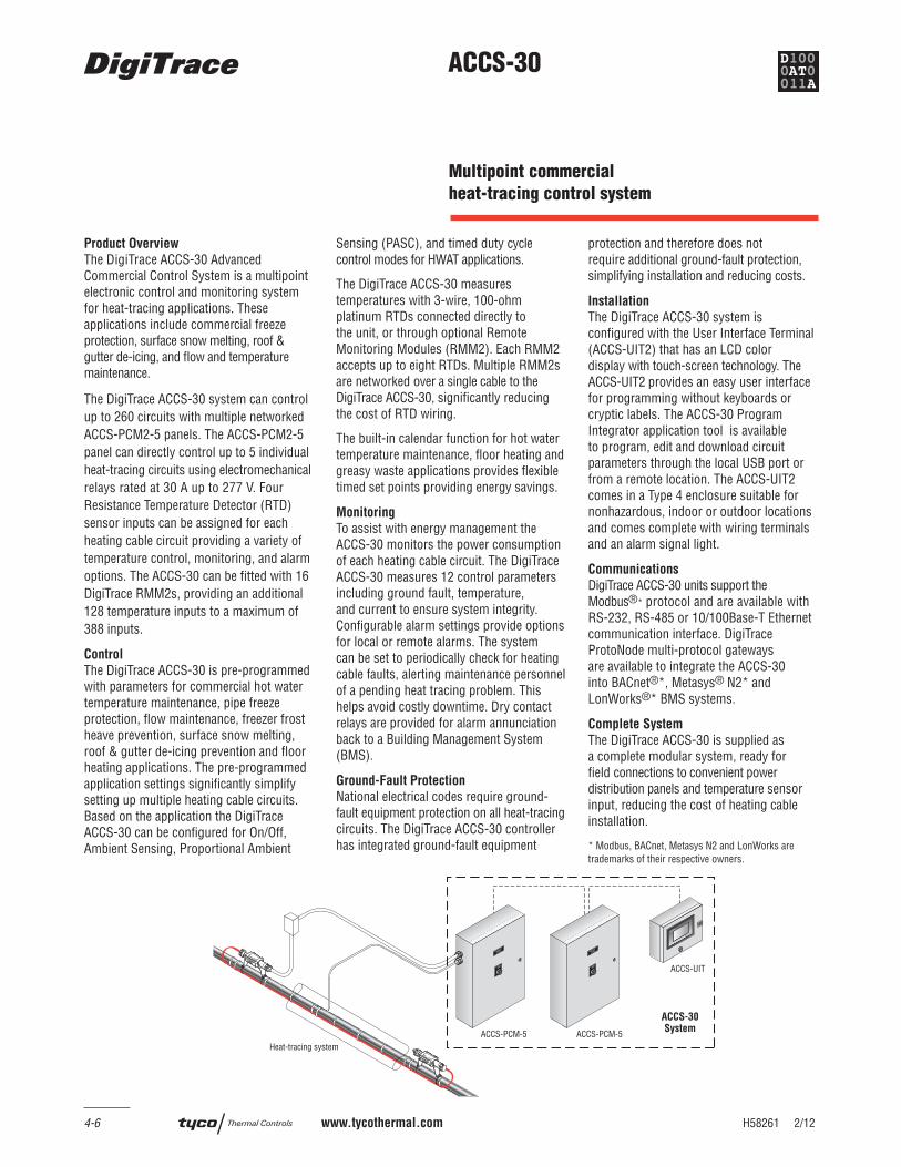
The DigiTrace ACCS-30 Advanced Commercial Control System is a multipoint electronic control and monitoring system for heat-tracing applications. These applications include commercial freeze protection, surface snow melting, roof & gutter de-icing, and fl ow and temperature maintenance.
The DigiTrace ACCS-30 system can control up to 260 circuits with multiple networked ACCS-PCM2-5 panels. The ACCS-PCM2-5 panel can directly control up to 5 individual heat-tracing circuits using electromechanical relays rated at 30 A up to 277 V. Four Resistance Temperature Detector (RTD) sensor inputs can be assigned for each heating cable circuit providing a variety of temperature control, monitoring, and alarm options. The ACCS-30 can be fi tted with 16 DigiTrace RMM2s, providing an additional 128 temperature inputs to a maximum of 388 inputs.
Control
The DigiTrace ACCS-30 is pre-programmed with parameters for commercial hot water temperature maintenance, pipe freeze protection, fl ow maintenance, freezer frost heave prevention, surface snow melting, roof & gutter de-icing prevention and fl oor heating applications. The pre-programmed application settings signifi cantly simplify setting up multiple heating cable circuits. Based on the application the DigiTrace ACCS-30 can be confi gured for On/Off, Ambient Sensing, Proportional Ambient
Sensing (PASC), and timed duty cycle control modes for HWAT applications.
The DigiTrace ACCS-30 measures temperatures with 3-wire, 100-ohm platinum RTDs connected directly to the unit, or through optional Remote Monitoring Modules (RMM2). Each RMM2 accepts up to eight RTDs. Multiple RMM2s are networked over a single cable to the DigiTrace ACCS-30, signifi cantly reducing the cost of RTD wiring.
The built-in calendar function for hot water temperature maintenance, fl oor heating and greasy waste applications provides fl exible timed set points providing energy savings.
Monitoring
To assist with energy management the ACCS-30 monitors the power consumption of each heating cable circuit. The DigiTrace ACCS-30 measures 12 control parameters including ground fault, temperature, and current to ensure system integrity. Confi gurable alarm settings provide options for local or remote alarms. The system can be set to periodically check for heating cable faults, alerting maintenance personnel of a pending heat tracing problem. This helps avoid costly downtime. Dry contact relays are provided for alarm annunciation back to a Building Management System (BMS).
Ground-Fault Protection
National electrical codes require ground-fault equipment protection on all heat-tracing circuits. The DigiTrace ACCS-30 controller has integrated ground-fault equipment
protection and therefore does not require additional ground-fault protection, simplifying installation and reducing costs.
Installation
The DigiTrace ACCS-30 system is confi gured with the User Interface Terminal (ACCS-UIT2) that has an LCD color display with touch-screen technology. The ACCS-UIT2 provides an easy user interface for programming without keyboards or cryptic labels. The ACCS-30 Program Integrator application tool is available to program, edit and download circuit parameters through the local USB port or from a remote location. The ACCS-UIT2 comes in a Type 4 enclosure suitable for nonhazardous, indoor or outdoor locations and comes complete with wiring terminals and an alarm signal light.
Communications
DigiTrace ACCS-30 units support theModbus®* protocol and are available with RS-232, RS-485 or 10/100Base-T Ethernet communication interface. DigiTrace ProtoNode multi-protocol gateways are available to integrate the ACCS-30 into BACnet®*, Metasys® N2* and LonWorks®* BMS systems.
Complete System
The DigiTrace ACCS-30 is supplied as a complete modular system, ready for fi eld connections to convenient power distribution panels and temperature sensor input, reducing the cost of heating cable installation.
* Modbus, BACnet, Metasys N2 and LonWorks are trademarks of their respective owners.
ACCS-PCM-5 ACCS-PCM-5
ACCS-UIT
ACCS-30System
COMMON
ALARM
POWER CONTROL
MODULE
ACCS-PCM-5
COMMON
ALARM
POWER CONTROL
MODULE
ACCS-PCM-5
Heat-tracing system
Multipoint commercial
heat-tracing control system
ACCS-30
H58261 2/12 www.tycothermal.com 4-7
1.
Desig
n G
uid
e2.
Desig
n N
ote
s3.
Desig
n E
xam
ple
s5.
Exp
ande
d C
apabilitie
s6.
Specifi ca
tion
7.
Warra
nty
4. Te
chnica
l Data
Sheets
ACCS-30 System
Multipoint temperature control with ground-fault/current/temperature monitoring when used with the ACCS-UIT2
The DigiTrace ACCS-30 is a multipoint electronic control, monitoring, and power relay system for heat-tracing cables used in commercial heat-tracing applications. The system consists of a DigiTrace ACCS-UIT2 and up to 52 ACCS-PCM2-5 power control panels. DigiTrace RMM2 heat-tracing remote monitoring modules may also be used with the ACCS-30 system to expand the number of temperature measurement points.
The DigiTrace ACCS-30 provides the following alarming features per control point.• High/low temperature• Ground fault• High/low current fault• RTD failure
The DigiTrace ACCS-30 provides ground-fault monitoring and protection for every heat-tracing circuit and fulfi lls the requirements of national electrical codes.
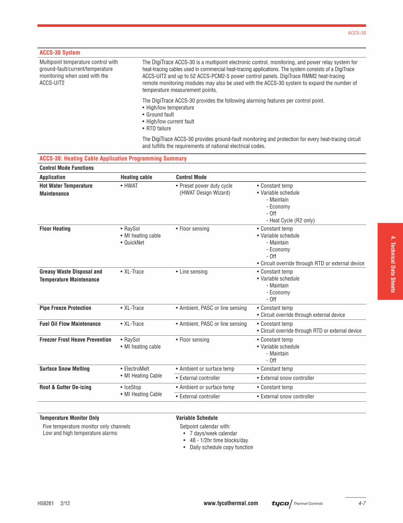
ACCS-30: Heating Cable Application Programming Summary
Control Mode Functions
Application Heating cable Control Mode Control setpoints
Hot Water Temperature
Maintenance
• HWAT • Preset power duty cycle(HWAT Design Wizard)
• Constant temp • Variable schedule
- Maintain- Economy- Off- Heat Cycle (R2 only)
Floor Heating • RaySol• MI heating cable• QuickNet
• Floor sensing • Constant temp • Variable schedule
- Maintain- Economy- Off
• Circuit override through RTD or external deviceGreasy Waste Disposal and
Temperature Maintenance
• XL-Trace • Line sensing • Constant temp • Variable schedule
- Maintain- Economy- Off
Pipe Freeze Protection • XL-Trace • Ambient, PASC or line sensing • Constant temp• Circuit override through external device
Fuel Oil Flow Maintenance • XL-Trace • Ambient, PASC or line sensing • Constant temp• Circuit override through RTD or external device
Freezer Frost Heave Prevention • RaySol• MI heating cable
• Floor sensing • Constant temp • Variable schedule
- Maintain- Off
Surface Snow Melting • ElectroMelt• MI Heating Cable
• Ambient or surface temp • Constant temp
• External controller • External snow controller
Roof & Gutter De-icing • IceStop• MI Heating Cable
• Ambient or surface temp • Constant temp
• External controller • External snow controller
Temperature Monitor Only Variable Schedule
Five temperature monitor only channelsLow and high temperature alarms
Setpoint calendar with:• 7 days/week calendar • 48 - 1/2hr time blocks/day • Daily schedule copy function
ACCS-30
4-8 www.tycothermal.com H58261 2/12
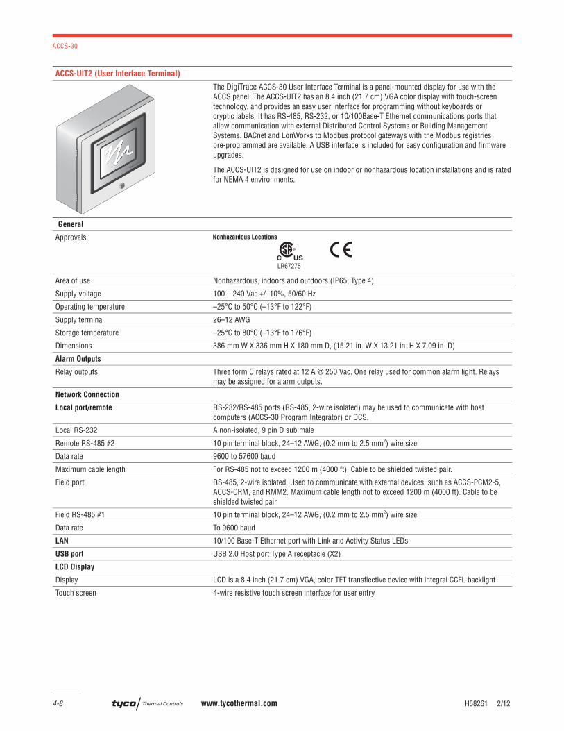
ACCS-UIT2 (User Interface Terminal)
The DigiTrace ACCS-30 User Interface Terminal is a panel-mounted display for use with the ACCS panel. The ACCS-UIT2 has an 8.4 inch (21.7 cm) VGA color display with touch-screen technology, and provides an easy user interface for programming without keyboards or cryptic labels. It has RS-485, RS-232, or 10/100Base-T Ethernet communications ports that allow communication with external Distributed Control Systems or Building Management Systems. BACnet and LonWorks to Modbus protocol gateways with the Modbus registries pre-programmed are available. A USB interface is included for easy confi guration and fi rmware upgrades.
The ACCS-UIT2 is designed for use on indoor or nonhazardous location installations and is rated for NEMA 4 environments.
General
Approvals
LR67275
Area of use Nonhazardous, indoors and outdoors (IP65, Type 4)
Supply voltage 100 – 240 Vac +/–10%, 50/60 Hz
Operating temperature –25°C to 50°C (–13°F to 122°F)
Supply terminal 26–12 AWG
Storage temperature –25°C to 80°C (–13°F to 176°F)
Dimensions 386 mm W X 336 mm H X 180 mm D, (15.21 in. W X 13.21 in. H X 7.09 in. D)
Alarm Outputs
Relay outputs Three form C relays rated at 12 A @ 250 Vac. One relay used for common alarm light. Relays may be assigned for alarm outputs.
Network Connection
Local port/remote RS-232/RS-485 ports (RS-485, 2-wire isolated) may be used to communicate with host computers (ACCS-30 Program Integrator) or DCS.
Local RS-232 A non-isolated, 9 pin D sub male
Remote RS-485 #2 10 pin terminal block, 24–12 AWG, (0.2 mm to 2.5 mm²) wire size
Data rate 9600 to 57600 baud
Maximum cable length For RS-485 not to exceed 1200 m (4000 ft). Cable to be shielded twisted pair.
Field port RS-485, 2-wire isolated. Used to communicate with external devices, such as ACCS-PCM2-5, ACCS-CRM, and RMM2. Maximum cable length not to exceed 1200 m (4000 ft). Cable to be shielded twisted pair.
Field RS-485 #1 10 pin terminal block, 24–12 AWG, (0.2 mm to 2.5 mm²) wire size
Data rate To 9600 baud
LAN 10/100 Base-T Ethernet port with Link and Activity Status LEDs
USB port USB 2.0 Host port Type A receptacle (X2)
LCD Display
Display LCD is a 8.4 inch (21.7 cm) VGA, color TFT transfl ective device with integral CCFL backlight
Touch screen 4-wire resistive touch screen interface for user entry
ACCS-30
H58261 2/12 www.tycothermal.com 4-9
1.
Desig
n G
uid
e2.
Desig
n N
ote
s3.
Desig
n E
xam
ple
s5.
Exp
ande
d C
apabilitie
s6.
Specifi ca
tion
7.
Warra
nty
4. Te
chnica
l Data
Sheets
ACCS-PCM2-5 Power Control Panel
HEAT TRACE CONTROL PANEL
MODEL NO: ACCS-PCM2-5
ENCLOSURE: TYPE 4, 12
SERIAL NO: XXXXXXXX-XXXX
VOLTAGE: MAX 277 VAC, 1PHASE, 2 WIRE, 60 HZ
SHORT CIRCUIT CURRENT 5kA RMS SYMMETRICAL,
277 VAC MAXIMUM
DANGER
MAXIMUM
277 VOLTS
TYCO THERMAL CONTROLS
7433 HARWIN DR
HOUSTON, TX 77036
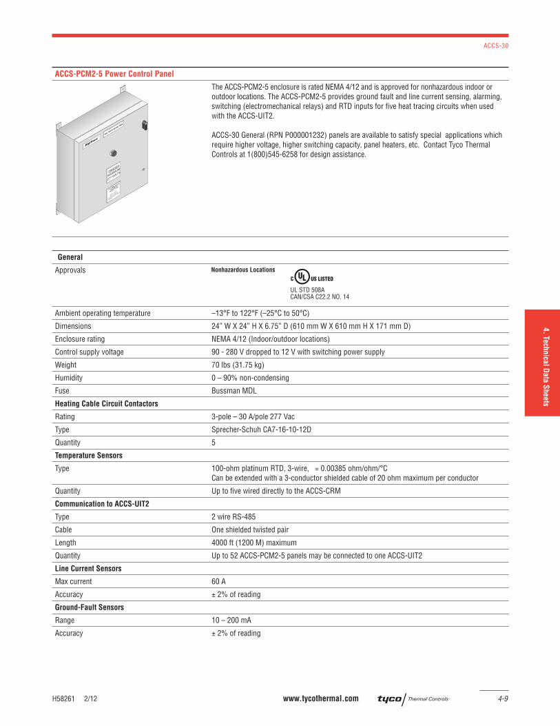
The ACCS-PCM2-5 enclosure is rated NEMA 4/12 and is approved for nonhazardous indoor or outdoor locations. The ACCS-PCM2-5 provides ground fault and line current sensing, alarming, switching (electromechanical relays) and RTD inputs for fi ve heat tracing circuits when used with the ACCS-UIT2.
ACCS-30 General (RPN P000001232) panels are available to satisfy special applications which require higher voltage, higher switching capacity, panel heaters, etc. Contact Tyco Thermal Controls at 1(800)545-6258 for design assistance.
General
Approvals
Ambient operating temperature –13°F to 122°F (–25°C to 50°C)
Dimensions 24” W X 24” H X 6.75” D (610 mm W X 610 mm H X 171 mm D)
Enclosure rating NEMA 4/12 (Indoor/outdoor locations)
Control supply voltage 90 - 280 V dropped to 12 V with switching power supply
Weight 70 lbs (31.75 kg)
Humidity 0 – 90% non-condensing
Fuse Bussman MDL
Heating Cable Circuit Contactors
Rating 3-pole – 30 A/pole 277 Vac
Type Sprecher-Schuh CA7-16-10-12D
Quantity 5
Temperature Sensors
Type 100-ohm platinum RTD, 3-wire, = 0.00385 ohm/ohm/°C Can be extended with a 3-conductor shielded cable of 20 ohm maximum per conductor
Quantity Up to fi ve wired directly to the ACCS-CRM
Communication to ACCS-UIT2
Type 2 wire RS-485
Cable One shielded twisted pair
Length 4000 ft (1200 M) maximum
Quantity Up to 52 ACCS-PCM2-5 panels may be connected to one ACCS-UIT2
Line Current Sensors
Max current 60 A
Accuracy ± 2% of reading
Ground-Fault Sensors
Range 10 – 200 mA
Accuracy ± 2% of reading
ACCS-30
4-10 www.tycothermal.com H58261 2/12
ACCS-PCM2-5 Power Control Panel (Continued)
Connection Terminals
Power Supply/Line/Load #22 – 8 AWG
RS-485 #24 – 12 AWG
RTD #24 – 12 AWG
Remote Monitoring Module (Optional)
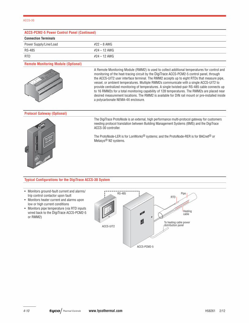
A Remote Monitoring Module (RMM2) is used to collect additional temperatures for control and monitoring of the heat-tracing circuit by the DigiTrace ACCS-PCM2-5 control panel, through the ACCS-UIT2 user interface terminal. The RMM2 accepts up to eight RTDs that measure pipe, vessel, or ambient temperatures. Multiple RMM2s communicate with a single ACCS-UIT2 to provide centralized monitoring of temperatures. A single twisted-pair RS-485 cable connects up to 16 RMM2s for a total monitoring capability of 128 temperatures. The RMM2s are placed near desired measurement locations. The RMM2 is available for DIN rail mount or pre-installed inside a polycarbonate NEMA-4X enclosure.
Protocol Gateway (Optional)
FRAME GND- PWR+PWR
RS 485+RS 485 -RS 485 GND
S3S2S1S0B3B2B1B0
A7A6A5A4A3A2A1A0
By FieldServer Technologies
www.ProtoCessor.com
PROTOCESSOR
SERIAL ETHERNET
PROTONODE
The DigiTrace ProtoNode is an external, high performance multi-protocol gateway for customers needing protocol translation between Building Management Systems (BMS) and the DigiTrace ACCS-30 controller.
The ProtoNode-LER is for LonWorks® systems; and the ProtoNode-RER is for BACnet® or Metasys® N2 systems.
Typical Configurations for the DigiTrace ACCS-30 System
Individual controls
• Monitors ground-fault current and alarms/trip control contactor upon fault
• Monitors heater current and alarms upon low or high current conditions
• Monitors pipe temperature (via RTD inputs wired back to the DigiTrace ACCS-PCM2-5 or RMM2)
ACCS-UIT2
RTD
Heatingcable
Pipe
COMMON
ALARM
POWER CONTROL
MODULE
ACCS-PCM-5
ACCS-PCM2-5
RS-485
To heating cable powerdistribution panel
ACCS-30
H58261 2/12 www.tycothermal.com 4-11
1.
Desig
n G
uid
e2.
Desig
n N
ote
s3.
Desig
n E
xam
ple
s5.
Exp
ande
d C
apabilitie
s6.
Specifi ca
tion
7.
Warra
nty
4. Te
chnica
l Data
Sheets
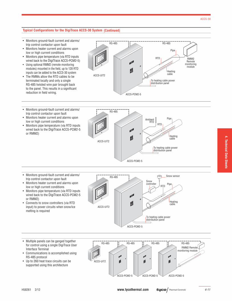
Typical Configurations for the DigiTrace ACCS-30 System
Individual controls with RMM2
• Monitors ground-fault current and alarms/trip control contactor upon fault
• Monitors heater current and alarms upon low or high current conditions
• Monitors pipe temperature (via RTD inputs wired back to the DigiTrace ACCS-PCM2-5)
• Using optional RMM2 (remote monitoring modules) mounted in the fi eld, up to 128 RTD inputs can be added to the ACCS-30 system
• The RMMs allow the RTD cables to be terminated locally and only a single RS-485 twisted wire pair brought back to the panel. This results in a signifi cant reduction in fi eld wiring.
RS-485RS-485
RMM2Remote
monitoringmodule
RTD
Heatingcable
Pipe
COMMON
ALARM
POWER CONTROL
MODULE
ACCS-PCM-5
ACCS-UIT2
ACCS-PCM2-5
To heating cable powerdistribution panel
Individual ambient control
• Monitors ground-fault current and alarms/trip control contactor upon fault
• Monitors heater current and alarms upon low or high current conditions
• Monitors pipe temperature (via RTD inputs wired back to the DigiTrace ACCS-PCM2-5 or RMM2)
To heating cable powerdistribution panel
ACCS-UIT2
AmbientRTD
RS-485
Heatingcable
Pipe
ACCS-PCM2-5
COMMON
ALARM
POWER CONTROL
MODULE
ACCS-PCM-5
RTD
Individual external control for surface snow melting and roof & gutter application
• Monitors ground-fault current and alarms/trip control contactor upon fault
• Monitors heater current and alarms upon low or high current conditions
• Monitors pipe temperature (via RTD inputs wired back to the DigiTrace ACCS-PCM2-5 or RMM2)
• Connects to snow controllers (via RTD input) to power circuits when snow/ice melting is required
To heating cable powerdistribution panel
ACCS-UIT2
RTD
RS-485
Heatingcable
Pipe
ACCS-PCM2-5
COMMON
ALARM
POWER CONTROL
MODULE
ACCS-PCM-5
Snow sensor
Snowcontroller
Multi-panel confi guration
• Multiple panels can be ganged together for control using a single DigiTrace User Interface Terminal
• Communications is accomplished using RS-485 protocol
• Up to 260 heat trace circuits can be supported using this architecture
ACCS-UIT2
RS-485 RS-485RS-485 RS-485
ACCS-PCM2-5
RMM2 Remotemonitoring module
ACCS-PCM2-5
COMMON
ALARM
POWER CONTROL
MODULE
ACCS-PCM-5
ACCS-PCM2-5
COMMON
ALARM
POWER CONTROL
MODULE
ACCS-PCM-5
COMMON
ALARM
POWER CONTROL
MODULE
ACCS-PCM-5
(Continued)
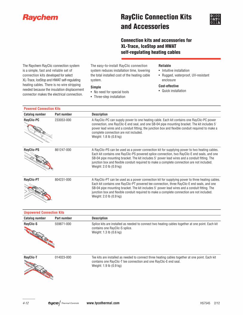
4-12 www.tycothermal.com H57545 2/12
RayClic Connection Kits
and Accessories
The Raychem RayClic connection system is a simple, fast and reliable set of connection kits developed for select XL-Trace, IceStop and HWAT self-regulating heating cables. There is no wire stripping needed because the insulation displacement connector makes the electrical connection.
The easy-to-install RayClic connection system reduces installation time, lowering the total installed cost of the heating cable system.
Simple
• No need for special tools• Three-step installation
Reliable
• Intuitive installation • Rugged, waterproof, UV-resistant
enclosure
Cost-effective
• Quick installation
Powered Connection Kits
Catalog number Part number Description
RayClic-PC 233053-000 A RayClic-PC can supply power to one heating cable. Each kit contains one RayClic-PC power connection, one RayClic-E end seal, and one SB-04 pipe mounting bracket. The kit includes 5' power lead wires and a conduit fi tting; the junction box and fl exible conduit required to make a complete connection are not included.Weight: 1.8 lb (0.8 kg)
RayClic-PS 861247-000 A RayClic-PS can be used as a power connection kit for supplying power to two heating cables. Each kit contains one RayClic-PS powered splice connection, two RayClic-E end seals, and one SB-04 pipe mounting bracket. The kit includes 5' power lead wires and a conduit fi tting. The junction box and fl exible conduit required to make a complete connection are not included.Weight: 2.0 lb (0.9 kg)
RayClic-PT 804231-000 A RayClic-PT can be used as a power connection kit for supplying power to three heating cables. Each kit contains one RayClic-PT powered tee connection, three RayClic-E end seals, and one SB-04 pipe mounting bracket. The kit includes 5' power lead wires and a conduit fi tting. The junction box and fl exible conduit required to make a complete connection are not included.Weight: 2.0 lb (0.9 kg)
Unpowered Connection Kits
Catalog number Part number Description
RayClic-S
RRayClic
WARNING: SHOCK HAZARD
Do not open while energized
RLISTED
DESIG. 3A, 3B, 3C, 2E
3 1/8"
559871-000 Splice kits are installed as needed to connect two heating cables together at one point. Each kit contains one RayClic-S splice. Weight: 1.3 lb (0.6 kg)
RayClic-T 014023-000 Tee kits are installed as needed to connect three heating cables together at one point. Each kit contains one RayClic-T tee connection and one RayClic-E end seal. Weight: 1.9 lb (0.9 kg)
Connection kits and accessories for
XL-Trace, IceStop and HWAT
self-regulating heating cables
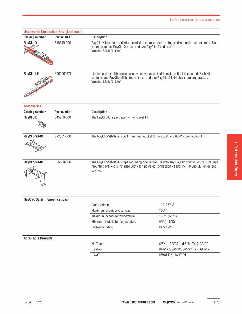
RayClic Connection Kits and Accessories
H57545 2/12 www.tycothermal.com 4-13
1.
Desig
n G
uid
e2.
Desig
n N
ote
s3.
Desig
n E
xam
ple
s5.
Exp
ande
d C
apabilitie
s6.
Specifi ca
tion
7.
Warra
nty
4. Te
chnica
l Data
Sheets
Unpowered Connection Kits
Catalog number Part number Description
RayClic-X
R
546349-000 RayClic-X kits are installed as needed to connect four heating cables together at one point. Each kit contains one RayClic-X cross and two RayClic-E end seals. Weight: 2.0 lb (0.9 kg)
RayClic-LE P000000770 Lighted end seal kits are installed wherever an end-of-line signal light is required. Each kit contains one RayClic-LE lighted end seal and one RayClic-SB-04 pipe mounting bracket.Weight: 1.8 lb (0.8 kg)
Accessories
Catalog number Part number Description
RayClic-E 805979-000 The RayClic-E is a replacement end seal kit.
RayClic-SB-02 852001-000 The RayClic-SB-02 is a wall mounting bracket for use with any RayClic connection kit.
RayClic-SB-04 616809-000 The RayClic-SB-04 is a pipe mounting bracket for use with any RayClic connection kit. One pipe mounting bracket is included with each powered connection kit and the RayClic-LE lighted end seal kit.
RayClic System Specifi cations
Rated voltage 120–277 V
Maximum circuit breaker size 30 A
Maximum exposure temperature 150°F (65°C)
Minimum installation temperature 0°F (–18°C)
Enclosure rating NEMA 4X
Applicable Products
XL-Trace 5/8XL1-CR/CT and 5/8/12XL2-CR/CT
IceStop GM-1XT, GM-1X, GM-2XT and GM-2X
HWAT HWAT-R2, HWAT-P1
(Continued)
RayClic Connection Kits and Accessories
4-14 www.tycothermal.com H57545 2/12
Approvals
Design and Installation For proper design and installation of a RayClic connection system, use the appropriate product design guide and the installation instructions included with the connection kit.
Ground-Fault Protection To minimize the danger of fi re from sustained electrical arcing if the heating cable is damaged or improperly installed, and to comply with the requirements of Tyco Thermal Controls, agency certifi cations, and national electrical codes, ground-fault equipment protection must be used on each heating cable branch circuit. Arcing may not be stopped by conventional circuit protection. Many DigiTrace control and monitoring systems meet the ground-fault protection requirement.
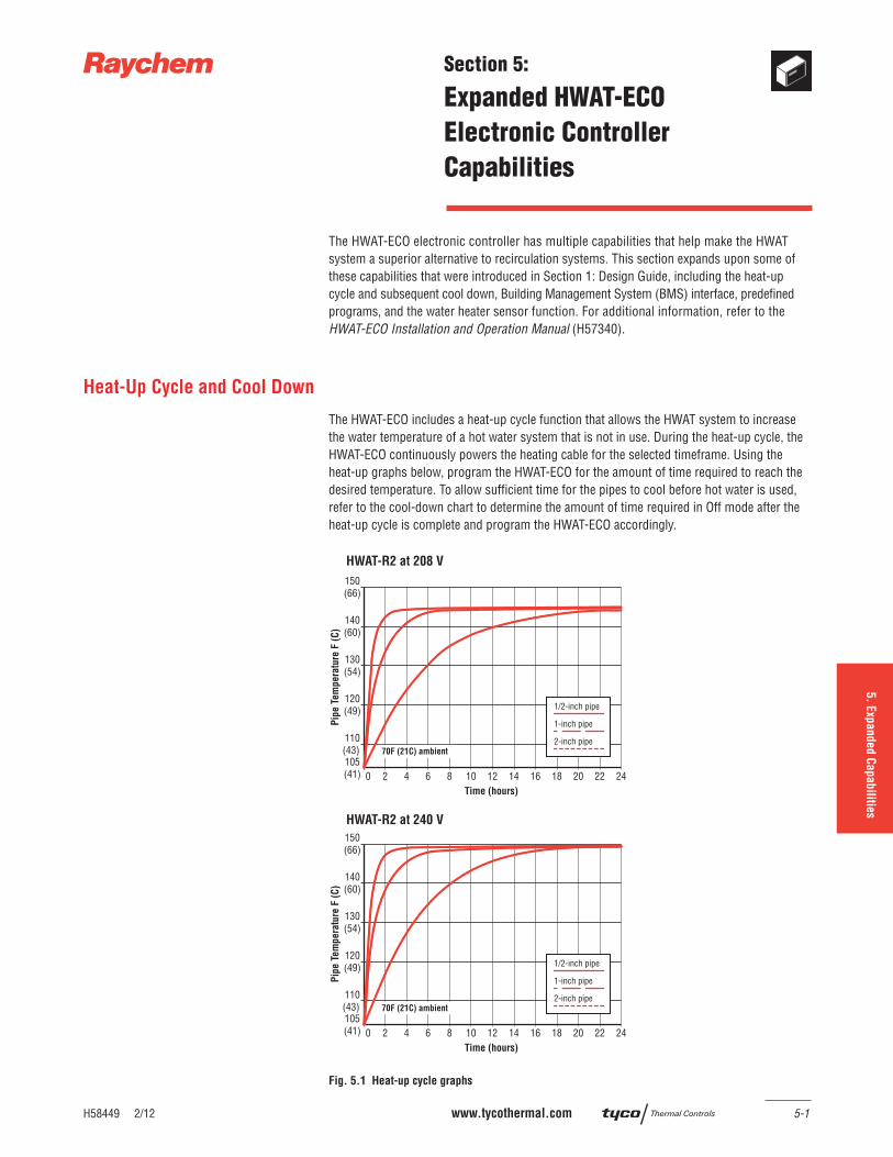
1.
Desig
n G
uid
e2.
Desig
n N
ote
s3.
Desig
n E
xam
ple
s4.
Tech
nica
l Data
sheets
5. E
xpanded C
apabilitie
s6.
Specifi ca
tion
7.
Warra
nty
H58449 2/12 www.tycothermal.com 5-1
Section 5:
Expanded HWAT-ECO
Electronic Controller
Capabilities
The HWAT-ECO electronic controller has multiple capabilities that help make the HWAT system a superior alternative to recirculation systems. This section expands upon some of these capabilities that were introduced in Section 1: Design Guide, including the heat-up cycle and subsequent cool down, Building Management System (BMS) interface, predefi ned programs, and the water heater sensor function. For additional information, refer to the HWAT-ECO Installation and Operation Manual (H57340).
Heat-Up Cycle and Cool Down
The HWAT-ECO includes a heat-up cycle function that allows the HWAT system to increase the water temperature of a hot water system that is not in use. During the heat-up cycle, the HWAT-ECO continuously powers the heating cable for the selected timeframe. Using the heat-up graphs below, program the HWAT-ECO for the amount of time required to reach the desired temperature. To allow suffi cient time for the pipes to cool before hot water is used, refer to the cool-down chart to determine the amount of time required in Off mode after the heat-up cycle is complete and program the HWAT-ECO accordingly.
Fig. 5.1 Heat-up cycle graphs
0 2 4 6 8 10 12 14 16 18 22 2420Time (hours)
150(66)
140(60)
130(54)
120(49)
110(43)
Pip
e T
em
pera
ture
F (
C)
105(41)
70F (21C) ambient
150(66)
140(60)
130(54)
120(49)
110(43) 105(41)
Time (hours)
Pip
e T
em
pera
ture
F (
C)
0 2 4 6 8 10 12 14 16 18 22 2420
70F (21C) ambient
HWAT-R2 at 208 V
HWAT-R2 at 240 V
1/2-inch pipe
1-inch pipe
2-inch pipe
1/2-inch pipe
1-inch pipe
2-inch pipe
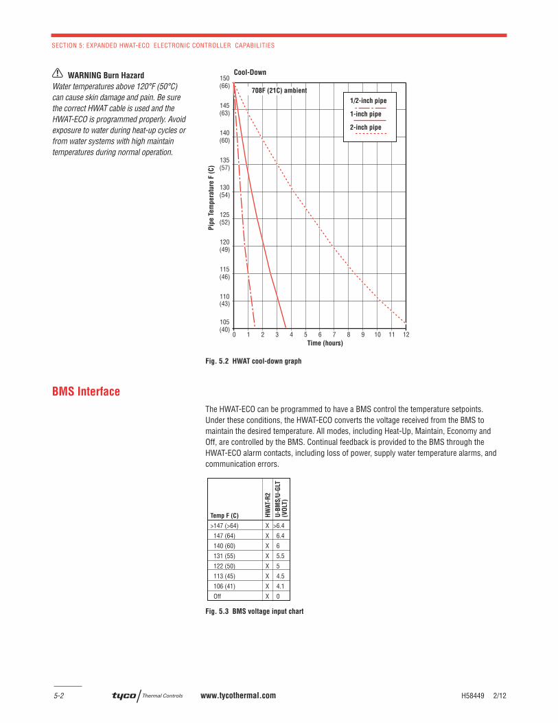
SECTION 5: EXPANDED HWAT-ECO ELECTRONIC CONTROLLER CAPABILITIES
5-2 www.tycothermal.com H58449 2/12
Fig. 5.2 HWAT cool-down graph
BMS Interface
The HWAT-ECO can be programmed to have a BMS control the temperature setpoints. Under these conditions, the HWAT-ECO converts the voltage received from the BMS to maintain the desired temperature. All modes, including Heat-Up, Maintain, Economy and Off, are controlled by the BMS. Continual feedback is provided to the BMS through the HWAT-ECO alarm contacts, including loss of power, supply water temperature alarms, and communication errors.
Fig. 5.3 BMS voltage input chart
WARNING Burn Hazard
Water temperatures above 120°F (50°C) can cause skin damage and pain. Be sure the correct HWAT cable is used and the HWAT-ECO is programmed properly. Avoid exposure to water during heat-up cycles or from water systems with high maintain temperatures during normal operation.
0 1 2 3 4 5 6 7 8 9 11 1210Time (hours)
Cool-Down150(66)
140(60)
130(54)
120(49)
110(43)
145(63)
135(57)
125(52)
115(46)
105(40)
Pip
e T
em
pera
ture
F (
C)
1/2-inch pipe
1-inch pipe
2-inch pipe
708F (21C) ambient
Temp F (C)
>147 (>64) X >6.4
147 (64) X 6.4
140 (60) X 6
131 (55) X 5.5
122 (50) X 5
113 (45) X 4.5
106 (41) X 4.1
Off X 0
HW
AT-
R2
U-B
MS
/U-G
LT(V
OLT
)
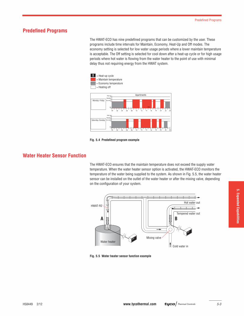
H58449 2/12 www.tycothermal.com 5-3
Predefi ned Programs
1.
Desig
n G
uid
e2.
Desig
n N
ote
s3.
Desig
n E
xam
ple
s4.
Tech
nica
l Data
sheets
6.
Specifi ca
tion
7.
Warra
nty
5. E
xpanded C
apabilitie
s
Predefi ned Programs
The HWAT-ECO has nine predefi ned programs that can be customized by the user. These programs include time intervals for Maintain, Economy, Heat-Up and Off modes. The economy setting is selected for low water usage periods where a lower maintain temperature is acceptable. The Off setting is selected for cool down after a heat-up cycle or for high usage periods where hot water is fl owing from the water heater to the point of use with minimal delay thus not requiring energy from the HWAT system.
Fig. 5.4 Predefi ned program example
Water Heater Sensor Function
The HWAT-ECO ensures that the maintain temperature does not exceed the supply water temperature. When the water heater sensor option is activated, the HWAT-ECO monitors the temperature of the water being supplied to the system. As shown in Fig. 5.5, the water heater sensor can be installed on the outlet of the water heater or after the mixing valve, depending on the confi guration of your system.
Fig. 5.5 Water heater sensor function example
Apartments
Monday–Friday
Heat-up
Saturday–Sunday
Heat-up
= Maintain temperature= Economy temperature= Heating off
00 06 12 18 2402 04 16141008 20 22
00 06 12 18 2402 04 16141008 20 22
max
Maintain
Maintain
Economy
Economy
Off
Off
= Heat-up cycle
A B
HWAT-R2
Water heaterMixing valve
Cold water in
Tempered water out
Hot water out

SECTION 5: EXPANDED HWAT-ECO ELECTRONIC CONTROLLER CAPABILITIES
5-4 www.tycothermal.com H58449 2/12
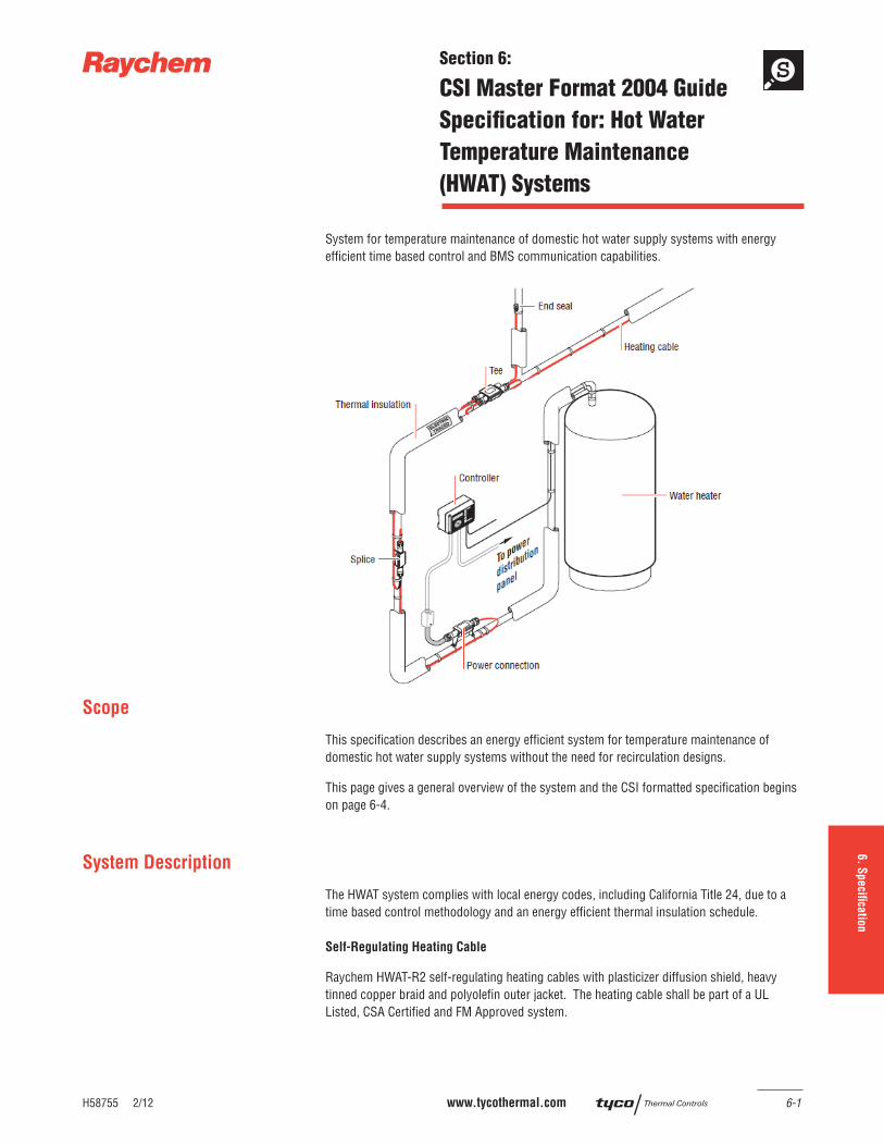
1.
Desig
n G
uid
e2.
Desig
n N
ote
s3.
Desig
n E
xam
ple
s4.
Tech
nica
l Data
sheets
5.
Exp
anded C
apabilitie
s6. S
pecifi ca
tion
7.
Warra
nty
H58755 2/12 www.tycothermal.com 6-1
Section 6:
CSI Master Format 2004 Guide
Specifi cation for: Hot Water
Temperature Maintenance
(HWAT) Systems
System for temperature maintenance of domestic hot water supply systems with energy effi cient time based control and BMS communication capabilities.
Scope
This specifi cation describes an energy effi cient system for temperature maintenance of domestic hot water supply systems without the need for recirculation designs.
This page gives a general overview of the system and the CSI formatted specifi cation begins on page 6-4.
System Description
The HWAT system complies with local energy codes, including California Title 24, due to a time based control methodology and an energy effi cient thermal insulation schedule.
Self-Regulating Heating Cable
Raychem HWAT-R2 self-regulating heating cables with plasticizer diffusion shield, heavy tinned copper braid and polyolefi n outer jacket. The heating cable shall be part of a UL Listed, CSA Certifi ed and FM Approved system.
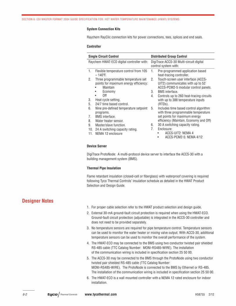
SECTION 6: CSI MASTER FORMAT 2004 GUIDE SPECIFICATION FOR: HOT WATER TEMPERATURE MAINTENANCE (HWAT) SYSTEMS
6-2 www.tycothermal.com H58755 2/12
System Connection Kits
Raychem RayClic connection kits for power connections, tees, splices and end seals.
Controller
Single Circuit Control Distributed Group Control
Raychem HWAT-ECO digital controller with: DigiTrace ACCS-30 Multi-circuit digital control system with:
1. Flexible temperature control from 105 – 140ºF.
2. Three programmable temperature set points for maximum energy effi ciency:• Maintain• Economy• Off
3. Heat cycle setting.5. 24/7 time based control.6. Nine pre-defi ned temperature setpoint
programs.7. BMS interface.8. Water heater sensor.9. Master/slave function.10. 24 A switching capacity rating.11. NEMA 12 enclosure
1. Pre-programmed application based heat-tracing controller.
2. Touch-screen user interface (ACCS-UIT2) communicates with up to 52 ACCS-PCM2-5 modular control panels.
3. BMS interface.4. Controls up to 260 heat-tracing circuits
with up to 388 temperature inputs (RTDs).
5. Includes time based control algorithm with three programmable temperature set points for maximum energy effi ciency (Maintain, Economy and Off)
6. 30 A switching capacity rating.7. Enclosure:
• ACCS-UIT2: NEMA 4• ACCS-PCM2-5: NEMA 4/12
Device Server
DigiTrace ProtoNode: A multi-protocol device server to interface the ACCS-30 with a building management system (BMS).
Thermal Pipe Insulation
Flame retardant insulation (closed-cell or fi berglass) with waterproof covering is required following Tyco Thermal Controls’ insulation schedule as detailed in the HWAT Product Selection and Design Guide.
Designer Notes
1. For proper cable selection refer to the HWAT product selection and design guide.
2. External 30-mA ground-fault circuit protection is required when using the HWAT-ECO. Ground-fault circuit protection (adjustable) is integrated in the ACCS-30 controller and does not need to be provided separately.
3. No temperature sensors are required for pipe temperature control. Temperature sensors can be used to monitor the water heater or mixing valve output. With ACCS-30, additional temperature sensors can be used to monitor the overall performance of the system.
4. The HWAT-ECO may be connected to the BMS using two conductor twisted pair shielded RS-485 cable (TTC Catalog Number: MONI-RS485-WIRE). The installation of the communication wiring is included in specifi cation section 25 50 00.
5. The ACCS-30 may be connected to the BMS through the ProtoNode using two conductor twisted pair shielded RS-485 cable (TTC Catalog Number: MONI-RS485-WIRE). The ProtoNode is connected to the BMS by Ethernet or RS-485.The installation of the communication wiring is included in specifi cation section 25 50 00.
6. The HWAT-ECO is a wall mounted controller with a NEMA 12 rated enclosure for indoor installation.
H58755 2/12 www.tycothermal.com 6-3
Drawing Details
1.
Desig
n G
uid
e2.
Desig
n N
ote
s3.
Desig
n E
xam
ple
s4.
Tech
nica
l Data
sheets
5.
Exp
anded C
apabilitie
s7.
Warra
nty
6. S
pecifi ca
tion
7. ACCS-UIT2 should be centrally located in the building connected to the remote ACCS-PCM2-5 control panels using RS-485 cable. The ACCS-PCM2-5 control panels may be located indoors or outdoors throughout the installation.
8. The location of the controller, power connection, tees/splices and end seals must be shown on the drawings.
Drawing Details
Installation details can be found at CADdetails.com under Hot Water Temperature Maintenance (HWAT) folder
SECTION 6: CSI MASTER FORMAT 2004 GUIDE SPECIFICATION FOR: HOT WATER TEMPERATURE MAINTENANCE (HWAT) SYSTEMS
6-4 www.tycothermal.com H58755 2/12
PART 1 - GENERAL
SUMMARY
A. This Section includes a UL Listed, CSA Certifi ed and FM Approved heat tracing system for temperature maintenance of domestic hot water supply systems consisting of self-regulating heating cable, connection kits and energy effi cient time based control.
B. The system complies with California Title 24 energy requirements.
RELATED SECTIONS
A. Section 22 05 33 – Heat Tracing for Plumbing Piping
B. Section 22 07 19 – Plumbing Piping Insulation
C. Section 25 34 00 – Integrated Automation Instrumentation and Terminal Devices for Plumbing
D. Section 25 54 00 – Integrated Automation Control of Plumbing
SYSTEM DESCRIPTION [Select one]
A. [Select for HWAT-ECO] System for temperature maintenance of domestic hot water supply systems with energy effi cient time based control, monitoring, and Building Management System (BMS) communication capabilities.
B. [Select for ACCS-30] System for temperature maintenance of domestic hot water supply systems with energy effi cient time based control, multi-point monitoring, integrated ground-fault circuit protection and Building Management System (BMS) communication capabilities.
SUBMITTALS
A. Product Data
1. Heating cable data sheet
2. UL, CSA, FM approval certifi cates for hot water temperature maintenance systems
3. Hot water temperature maintenance design guide
4. System installation and operation manual
5. System installation details
6. Connection kits and accessories data sheet
7. Controller data sheet
8. Controller wiring diagram
QUALITY ASSURANCE
A. Manufacturers Qualifi cations
1. Manufacturer to show minimum of thirty (30) years experience in manufacturing electric self-regulating heating cables.
2. Manufacturer will be ISO-9001 registered.
3. Manufacturer to provide products consistent with UL 515, CSA 22.2 No 130-03 and IEEE 515.1 requirements.
B. Installer Qualifi cation
1. System installer shall have complete understanding of product and product literature from manufacturer or authorized representative prior to installation. Electrical connections shall be performed by a licensed electrician.
C. Regulatory Requirements and Approvals
1. The system (heating cable, connection kits, and controller) shall be UL Listed, CSA Certifi ed and FM Approved for hot water temperature maintenance.
H58755 2/12 www.tycothermal.com 6-5
PART 2 - PRODUCTS
1.
Desig
n G
uid
e2.
Desig
n N
ote
s3.
Desig
n E
xam
ple
s4.
Tech
nica
l Data
sheets
5.
Exp
anded C
apabilitie
s7.
Warra
nty
6. S
pecifi ca
tion
D. Electrical Components, Devices, and Accessories: Listed and labeled as defi ned in NFPA 70, Article 100, by a Nationally Recognized Testing Laboratory (NRTL), and marked for intended use.
DELIVERY, STORAGE AND HANDLING
A. General Requirements: Deliver, store and handle products to prevent their deterioration or damage due to moisture, temperature changes, contaminates or other causes.
B. Delivery and Acceptance Requirements: Deliver products to site in original, unopened containers or packages with intact and legible manufacturers’ labels identifying the following:
1. Product and Manufacturer
2. Length/Quantity
3. Lot Number
C. Storage and Handling Requirements
1. Store the heating cable in a clean, dry location with a temperature range 0°F (-18°C) to 140°F (60°C).
2. Protect the heating cable from mechanical damage.
WARRANTY
A. Extended Warranty
1. Manufacturer shall offer a ten (10) year warranty for all heating cables and components. Provide one (1) year warranty for all heat trace controllers.
2. Contractor shall submit to owner results of installation tests required by the manufacturer.
PART 2 - PRODUCTS
MANUFACTURERS AND PRODUCTS
A. Contract Documents are based on manufacturer and products named below to establish a standard of quality.
B. Basis of Design
1. Basis of Design Product Selections
a. Manufacturer
1. Manufacturers shall have more than thirty (30) years experience with manufacture & installation self-regulating heating cables.
2. Manufacturer shall provide UL, CSA, FM approval certifi cates for hot wa-ter temperature maintenance system.
3. Manufacturer shall be Tyco Thermal Controls, LLC, located at, 7433 Har-win Drive, Houston, TX 77036Tel: (800) 545-6258 www.tycothermal.com
b. Hot Water Temperature Maintenance System
1. Raychem HWAT self-regulating heating cables with plasticizer diffusion shield, heavy tinned copper braid and polyolefi n outer jacket.
2. Raychem RayClic and accessories.
3. Raychem HWAT-ECO or ACCS-30 [Select one] digital controller
4. DigiTrace ProtoNode multi-protocol device server.
5. The HWAT system complies with local energy codes, including California Title 24, due to a time based control methodology (HWAT-ECO or ACCS-30 [Select one]) and an energy effi cient thermal insulation schedule.
SECTION 6: CSI MASTER FORMAT 2004 GUIDE SPECIFICATION FOR: HOT WATER TEMPERATURE MAINTENANCE (HWAT) SYSTEMS
6-6 www.tycothermal.com H58755 2/12
PRODUCTS, GENERAL
A. Single Source Responsibility: Furnish heat tracing system for the temperature maintenance of domestic hot water supply systems from a single manufacturer.
B. The system (heating cable, connection kits, and controller) shall be UL Listed, CSA Certifi ed and FM Approved for hot water temperature maintenance. No parts of the system may be substituted or exchanged.
PRODUCTS
A. Self-Regulating Heating Cable
1. Heating cable shall be Raychem HWAT-R2 self-regulating heating cable manufactured by Tyco Thermal Controls.
2. The heating cable shall consist of a continuous core of conductive polymer that is radiation cross-linked, extruded between two (2) 16 AWG nickel-plated copper bus wires that varies its power output in response to pipe temperature changes.
3. The heating cable shall have a modifi ed polyolefi n inner jacket for dielectric integrity.
4. The heating cable shall have a plasticizer diffusion shield.
5. The heating cable shall have a thicker gauge (5/24) tinned copper braid for ground path and mechanical ruggedness.
6. The heating cable shall have a color coded polyolefi n outer jacket.
7. The heating cable shall have a self-regulating factor of at least or at least 70 percent for HWAT-R2. The self-regulating factor is defi ned as the percent reduction of the heating cable power output going from a 40°F pipe temperature to 150oF pipe temperature.
8. The heating cable shall operate on line voltages of 208, 220, 240 or 277 volts without the use of transformers. [Select one]
9. The heating cable shall be UL part of a UL Listed, CSA Certifi ed and FM Approved system.
10. The outer jacket of the heating cable shall have the following markings:
a. Heating cable model number
b. Agency listings
c. Meter mark
d. Lot/Batch ID
B. Heating Cable Connection Kits
1. Heating cable connection kits shall be Raychem RayClic.
2. Manufacturer shall provide power connection, splice/tee and end seal kits compatible with selected heating cable.
3. Installation shall not require the installing contractor to cut into the heating-cable core to expose the bus wires.
4. Connection kits shall be rated NEMA 4X to prevent water ingress and corrosion. All connection kits shall be UV resistant .
5. Connection kits shall be UL Listed, CSA Certifi ed and FM Approved.
C. Heating Cable Installation Accessories
1. High temperature, glass fi lament tape for attachment of heating cable to water lines. Metal cable ties are not permitted. (TTC Catalog Number: GT-66)
2. Plastic Piping – provide an aluminum self-adhesive tape to be installed over the heating cable on all plastic piping if required. (TTC Catalog Number: AT-180)
3. Labels – Provide warning labels to be installed every 10 feet on exterior of insulation, opposite sides of pipe. (TTC Catalog Number: ETL)
H58755 2/12 www.tycothermal.com 6-7
PART 2 - PRODUCTS
1.
Desig
n G
uid
e2.
Desig
n N
ote
s3.
Desig
n E
xam
ple
s4.
Tech
nica
l Data
sheets
5.
Exp
anded C
apabilitie
s7.
Warra
nty
6. S
pecifi ca
tion
D. Energy Effi cient Time Based Control [Select one option]
1. [Option 1] Single Circuit Local Digital Controller
a. Local digital controller shall be the Raychem HWAT-ECO.
b. Digital controller shall operate on 208 – 240 V.
c. Pre-programmed duty cycles based on ambient temperature ranging from 60 – 80oF.
d. The pre-programmed duty cycles shall be based on Raychem HWAT heating cables only. No other heating cables may be used with the HWAT-ECO controller.
e. Flexible temperature control from 105 – 140oF.
f. Three programmable temperature set points for maximum energy effi ciency:
1. Maintain
2. Economy
3. Off
g. Controller shall have heat cycle setting.
h. Heating cable manufacturer shall provide a local digital controller with 24/7 pre-programmed time based profi les specifi c to the selected heating cable application such as schools, hospitals and prisons.
i. Controller shall have remote temperature setting through 0 – 10 Vdc BMS interface.
j. Controller shall have a water heater sensor and water heater temperature alarm:
1. To maximize the energy effi ciency of the HWAT system by verifying that the hot water supply is at the correct temperature (low temperature alarm).
2. To monitor and alarm if the supply water temperature is hotter than intended (high temperature alarm).
k. Multiple HWAT-ECO controllers can be networked together (master/slave association):
1. Allows BMS to interface with a master HWAT-ECO to control cloned circuits
2. Minimizes the number of HWAT-ECO controllers that must be individually programmed
l. Controller shall have 24 A switching capacity rating.
m. Enclosure type shall be NEMA 12 (ABS).
n. Controller shall have NO/NC alarm contacts. Controller shall alarm on:
1. Loss of power
2. Controller reinitialized
3. Internal controller temperature too high
4. Water heater temperature too high
5. Water heater temperature too low
6. Master/slave error
o. Digital controller shall have c-UL-us approvals specifi cally for use with HWAT-R2 heating cables.
2. [Option 2] Multiple Circuit Distributed Digital Control System
a. Distributed digital control system shall be DigiTrace ACCS-30 heat-trace control system.
SECTION 6: CSI MASTER FORMAT 2004 GUIDE SPECIFICATION FOR: HOT WATER TEMPERATURE MAINTENANCE (HWAT) SYSTEMS
6-8 www.tycothermal.com H58755 2/12
b. Heating cable manufacturer shall provide a distributed digital control system with pre-programmed parameters to provide concurrent control for heating cables used for pipe freeze protection, fl ow maintenance, hot water temperature maintenance, surface snow melting, roof and gutter de-icing, freezer frost heave prevention and fl oor heating applications.
c. All programming shall be done through the central User Interface Terminal(ACCS-UIT2).
d. The ACCS-UIT2 shall be a color LCD touch-screen display with password protection to prevent unauthorized access to the system.
e. The ACCS-UIT2 shall communicate with up to fi fty-two (52) ACCS Power Control Panels (ACCS-PCM2-5) where each panel can control up to fi ve (5) circuits and accept up to fi ve (5) temperature inputs.
f. Digital control system shall be capable of assigning up to four (4) RTD temperature inputs per heat-tracing circuit.
g. The ACCS-UIT2 shall communicate with up to sixteen (16) Remote Monitoring Modules (RMM2), where each module can accept up to 8 temperature inputs.
h. The ACCS-UIT2 shall have a USB port to allow for quick and easy software update.
i. The ACCS-UIT2 shall have three (3) programmable alarm contacts including an alarm light on the enclosure cover.
j. A separate offl ine software tool shall be made available to allow users to pre-program the digital control system and transfer program via a USB drive or Ethernet.
k. The ACCS-UIT2 enclosure shall be NEMA 4 for indoor or outdoor locations.
l. The ACCS-PCM2-5 panel shall be in a NEMA 4/12 enclosure approved fornonhazardous indoor and outdoor locations.
m. The ACCS-PCM2-5 panel shall provide ground-fault and line current sensing, alarming, switching and temperature inputs for fi ve (5) heat tracing circuits.
n. Each ACCS-PCM2-5 panel shall have fi ve (5) 3-pole, 30 A contactors (EMR type).
o. The ACCS-PCM2-5 panel shall be capable of operating at 120 V to 277 V.
p. The ACCS-PCM2-5 shall have an alarm contact including an alarm light on the panel cover.
q. Digital controller shall have an integrated adjustable GFPD (10 – 200 mA).
r. Digital control system can be confi gured for On/Off, ambient sensing, PASC and timed duty cycle control (HWAT only) modes based on the application. PASC control proportionally energizes the power to the heating cable to minimize energy based on ambient sensed conditions.
s. Upon communication loss with the user interface terminal (ACCS-UIT2) the ACCS-PCM2-5 panels shall control with the last downloaded set point.
t. In HWAT control mode, the ACCS-30 shall have time based control algorithm with three programmable temperature setpoints for maximum energy effi ciency (Maintain, Economy and Off)
u. In HWAT control mode, the pre-programmed duty cycles shall be based on Raychem HWAT heating cables only. No other heating cables may be used in the HWAT control mode.
v. Digital control system will have a built-in self-test feature to verify proper functionality of heating cable system.
H58755 2/12 www.tycothermal.com 6-9
PART 3 - EXECUTION
1.
Desig
n G
uid
e2.
Desig
n N
ote
s3.
Desig
n E
xam
ple
s4.
Tech
nica
l Data
sheets
5.
Exp
anded C
apabilitie
s7.
Warra
nty
6. S
pecifi ca
tion
w. Digital control system will also be able to communicate with BMS by one of the following protocols using the DigiTrace ProtoNode multi-protocol gateway. [Select one]
1. LonWorks® [Select ProtoNode-LER]
2. BACnet® [Select ProtoNode-RER]
3. Metasys® N2 [Select ProtoNode-RER]
x. The following variables will be monitored by the digital controller and reported back to the BMS.
1. Temperature
2. Ground-fault
3. Current
4. Power consumption
5. Associated alarms
y. The ACCS-UIT2 shall be c-CSA-us Certifi ed. The ACCS-PCM2-5 panel shall be c-UL-us Listed.
E. Thermal Pipe Insulation
1. Pipes must be thermally insulated in accordance with the HWAT Design Guide requirements.
2. Thermal insulation must be a type that is fl ame retardant (closed-cell or fi berglass) with waterproof covering.
SYSTEM LISTING
A. The system (heating cable, connection kits, and controller) shall be UL Listed, CSA Certifi ed and FM Approved for hot water temperature maintenance.
B. The temperature maintenance system shall have a design, installation and operating manual specifi c to domestic hot water piping.
PART 3 - EXECUTION
INSTALLERS
A. Acceptable Installers
1. Subject to compliance with requirements of Contract Documents, installer shall be familiar with installing heat-trace cable and equipment.
INSTALLATION
A. Comply with manufacturer’s recommendations in the HWAT System Installation and Operation Manual.
B. Apply the heating cable linearly on the pipe after piping has successfully completed any pressure tests. Secure the heating cable to piping with fi berglass tape.
C. Install electric heating cable according to the drawings and the manufacturer’s instructions. The installer shall be responsible for providing a complete functional system, installed in accordance with applicable national and local requirements.
D. Grounding of controller shall be equipment according to Section 26 05 26 “Grounding and Bonding for Electrical Systems.”
E. Connection of all electrical wiring shall be according to Section 26 05 19 “Low-Voltage Electrical Power Conductors and Cables.”
F. Pipes must be thermally insulated in accordance with the HWAT design guide requirements.
SECTION 6: CSI MASTER FORMAT 2004 GUIDE SPECIFICATION FOR: HOT WATER TEMPERATURE MAINTENANCE (HWAT) SYSTEMS
6-10 www.tycothermal.com H58755 2/12
FIELD QUALITY CONTROL
A. Initial start-up and fi eld testing (commissioning) of the system shall be performed by factory technician or factory representative per the owner’s requirements.
B. Field Testing and Inspections
1. The system shall be commissioned in accordance to the HWAT Installation and Operation manual.
2. The heating cable circuit integrity shall be tested using a 2500 Vdc megohmmeter at the following intervals;
a. Before installing the heating cable
b. After heating cable has been installed onto the pipe
c. After installing connection kits
d. After the thermal insulation is installed onto the pipe
e. Prior to initial start-up (commissioning)
f. As part of the regular system maintenance
g. Minimum acceptable insulation resistance shall be 1000 megohms or greater
3. The technician shall verify the insulation schedule is in compliance with the HWAT Installation and Operation manual.
4. The technician shall verify that the HWAT-ECO or ACCS-30 [Select one] control parameters are set to the application requirements.
5. The technician shall verify that the HWAT-ECO or ACCS-30 [Select one] alarm contacts are corrected connected to the BMS.
6. The technician shall verify that the ACCS-30 and ProtoNode-RER/-LER [Select one] are confi gured correctly with the BMS.
7. All commissioning results will be recorded and presented to the owner.
MAINTENANCE
A. Maintenance Service
1. Comply with manufacturer’s recommendations in HWAT System Installation and Operation Manual.
1.
Desig
n G
uid
e2.
Desig
n N
ote
s3.
Desig
n E
xam
ple
s4.
Tech
nica
l Data
sheets
5.
Exp
anded C
apabilitie
s6.
Specifi ca
tion
7. W
arra
nty
H58501 2/12 www.tycothermal.com 7-1
Section 7:
Limited Warranty
Tyco Thermal Controls warrants all Industrial, Commercial Construction, and Wholesale Distribution Heating Products as well as all Industrial and Commercial Wiring products against faulty workmanship and use of defective materials when such goods are properly installed, operated, and maintained according to product documentation. All documentation regarding proper use and installation can be found on our web site at www.tycothermal.com. Goods subjected to misuse, neglect, alteration or improper installation, operation, maintenance, repair or testing (or such other act or omissions not attributable to Tyco Thermal Controls) are not covered by this Limited Warranty. Tyco Thermal Controls shall in no event be liable for the cost of removal or installation, for loss or damage to or loss of use of facilities or other property, loss of revenue, loss of use of revenue, loss of anticipated profi ts, or other damages or costs of any kind whatsoever, whether direct, indirect, incidental, or consequential, and in no event shall Tyco Thermal Controls’ liability exceed an amount equal to the sales price. This warranty remains in force for a period of 18 months from installation or 24 months from the date of shipment, whichever occurs fi rst with respect to Industrial and Commercial Construction Heating and Wiring Products and two (2) years from the date of purchase with respect to Wholesale Distribution Heating Products. Tyco Thermal Controls will examine and confi rm that any alleged product issue covered by this Limited Warranty actually exists and occurred in the course of proper and normal use and was not caused by accident, misuse, neglect, alteration or improper installation, operation, maintenance, repair or testing or such other cause outside of the responsibility of Tyco Thermal Controls under this Limited Warranty. Tyco Thermal Controls will repair such goods or supply replacement goods or credit Buyer’s account for goods covered by this Limited Warranty whichever Tyco Thermal Controls may elect at its sole discretion. The Buyer should promptly notify Tyco Thermal Controls, or their Tyco Thermal Controls’ Representative, either by writing or by email within thirty (30) days after discovery of an alleged warranty issue. Detailed warranty claim information will be requested at this time and must be supplied by the Buyer. The Buyer may then be asked to return the goods, postage paid, to the location given by Tyco Thermal Controls.
THE FOREGOING WARRANTY IS IN LIEU OF ALL OTHER REPRESENTATIONS, WARRANTIES, OR CONDITIONS, EXPRESS OR IMPLIED, INCLUDING WITHOUT LIMITATION ANY IMPLIED WARRANTY OF MERCHANTABILITY, FITNESS FOR A PARTICULAR PURPOSE OR NONINFRINGEMENT, AND OF ANY OTHER OBLIGATION OR LIABILITY ON THE PART OF TYCO THERMAL CONTROLS, WHETHER BY STATUTE, CONTRACT, STRICT LIABILITY, TORT OR OTHERWISE.
An extension of the limited warranty period to ten (10) years from the date of installation is available if a properly completed online warranty form is completed within thirty (30) days from the date of installation. The extension is valid for the HWAT-R2 heating cable, RayClic connection kits and accessories but not the HWAT-ECO controller. Complete warranty information and the 10-Year warranty extension form can be found at www.tycothermal.com.

www.tycothermal.com 2/12
NOTES:

© 2
012
Tyco
The
rmal
Con
trols
LLC
H
5753
8
02/1
2
Important: All information, including illustrations, is believed to be reliable. Users, however, should independently evaluate the suitability of each product for their particular application. Tyco Thermal Controls makes no warranties as to the accuracy or completeness of the information, and disclaims any liability regarding its use. Tyco Thermal Controls’ only obligations are those in the Tyco Thermal Controls Standard Terms and Conditions of Sale for this product, and in no case will Tyco Thermal Controls or its distributors be liable for any incidental, indirect, or consequential damages arising from the sale, resale, use, or misuse of the product. Specifications are subject to change without notice. In addition, Tyco Thermal Controls reserves the right to make changes—without notification to Buyer—to processing or materials that do not affect compliance with any applicable specification.
Tyco, DigiTrace, HWAT and RayClic are trademarks registered and/or unregistered of Tyco Thermal Controls LLC or its affiliates. All other trademarks are the property of their respective owners.
Worldwide HeadquartersTyco Thermal Controls7433 Harwin DriveHouston, TX 77036USA Tel: 800-545-6258 Tel: 650-216-1526 Fax: 800-527-5703Fax: [email protected] www.tycothermal.com
Latin AmericaTyco Thermal Controls Al. Araguaia, 2044 – Sala.1101, Bloco BEdificio CEA – AlphavilleBarueri – Sao Paulo – Brasil06455-000Tel: +55 11 2588 1400Fax: +55 11 2588 1410
Europe, Middle East, Africa Tyco Thermal ControlsRomeinse Straat 143001 LeuvenBelgië / BelgiqueTel: +32 16 213 511Fax: +32 16 213 603
Asia PacificTyco Thermal Controls 20F, Innovation Building, 1009 Yi Shan Rd,Shanghai 200233, P.R.ChinaTel: +86 21 2412 1688Fax: +86 21 5426 2937 / 5426 3167


![RAYCHEM Tubing Products SCL 1 - Allied Electronics · Series UL Military Raychem ... 21.8 [0.857] 2.41 ± 0.51 [0.095 ± 0.020] 1 3/4 44.5 [1.750] 25.4 [1.000] ... and bus bar insulation,](https://img.pdfslide.net/doc/110x75/5b2f376c7f8b9ae16e8d0a9a/raychem-tubing-products-scl-1-allied-electronics-series-ul-military-raychem.jpg)