Embed Size (px)
Citation preview

HP Modular Power Distribution Unit Kit Installation Instructions
Overview These installation instructions are provided to assist qualified personnel with the installation of the HP Modular Power Distribution Unit (mPDU) Kit.
The input voltage of a single phase mPDU is either 100 to 127 VAC or 200 to 240 VAC, depending on the model.
The input voltage of a three phase mPDU is 200 to 240 VAC, phase-phase or phase-neutral, depending on the model.
The control unit (if included) provides the following features:
• Flexible mounting in 0U or 1U configurations, maximizing rack space (no additional parts are required for mounting)
• Overcurrent and short-circuit protection for each output (UL-489-listed circuit breakers)
• Manual on/off control for each of the output load groups
• Pilot light for main AC input (depending on the model)
• IEC-320 C19 outlets to power extension bars or other IEC-320 C20 plug-compatible equipment
• Easy identification and reset of overload circuits (circuit breakers move to Off position), minimizing downtime
• Power cord retention
• Recessed handles to prevent inadvertent power-off
The extension bars (if included) provide the following features:
• Multiple power outlets, conveniently located for quick and easy equipment power connections
• Lighted main power indicator
• Attached 2-m (6-ft) input power cords
• Power cord retention and power cord labeling
Modular PDU models To view the most recent modular PDU information, see the HP website (http://www.hp.com/go/rackandpower).
From there, you can navigate to the appropriate page by following the steps below.
1. Click Power infrastructure.
2. Click Power distribution units.
3. Click Modular.
© Copyright 2006, 2008 Hewlett-Packard Development Company, L.P.
The information contained herein is subject to change without notice. The onlywarranties for HP products and services are set forth in the express warranty statements accompanying such products and services. Nothing herein should be construed as constituting an additional warranty. HP shall not be liable for technical or editorial errors or omissions contained herein.
Part Number 240824-4 2 October 2008 (Tenth Edition)
0
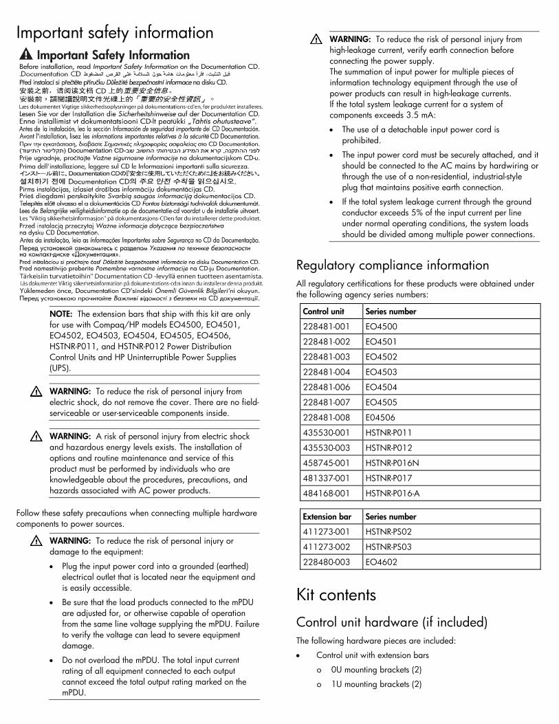
Important safety information
NOTE: The extension bars that ship with this kit are only for use with Compaq/HP models EO4500, EO4501, EO4502, EO4503, EO4504, EO4505, EO4506, HSTNR-P011, and HSTNR-P012 Power Distribution Control Units and HP Uninterruptible Power Supplies (UPS).
WARNING: To reduce the risk of personal injury from electric shock, do not remove the cover. There are no field-serviceable or user-serviceable components inside.
WARNING: A risk of personal injury from electric shock and hazardous energy levels exists. The installation of options and routine maintenance and service of this product must be performed by individuals who are knowledgeable about the procedures, precautions, and hazards associated with AC power products.
Follow these safety precautions when connecting multiple hardware components to power sources.
WARNING: To reduce the risk of personal injury or damage to the equipment:
• Plug the input power cord into a grounded (earthed) electrical outlet that is located near the equipment and is easily accessible.
• Be sure that the load products connected to the mPDU are adjusted for, or otherwise capable of operation from the same line voltage supplying the mPDU. Failureto verify the voltage can lead to severe equipment damage.
• Do not overload the mPDU. The total input current rating of all equipment connected to each output cannot exceed the total output rating marked on the mPDU.
WARNING: To reduce the risk of personal injury from high-leakage current, verify earth connection before connecting the power supply. The summation of input power for multiple pieces of information technology equipment through the use of power products can result in high-leakage currents. If the total system leakage current for a system of components exceeds 3.5 mA:
• The use of a detachable input power cord is prohibited.
• The input power cord must be securely attached, and it should be connected to the AC mains by hardwiring or through the use of a non-residential, industrial-style plug that maintains positive earth connection.
• If the total system leakage current through the ground conductor exceeds 5% of the input current per line under normal operating conditions, the system loads should be divided among multiple power connections.
Regulatory compliance information All regulatory certifications for these products were obtained under the following agency series numbers:
Control unit Series number
228481-001 EO4500
228481-002 EO4501
228481-003 EO4502
228481-004 EO4503
228481-006 EO4504
228481-007 EO4505
228481-008 E04506
435530-001 HSTNR-P011
435530-003 HSTNR-P012
458745-001 HSTNR-P016N
481337-001 HSTNR-P017
484168-001 HSTNR-P016-A
Extension bar Series number
411273-001 HSTNR-PS02
411273-002 HSTNR-PS03
228480-003 EO4602
Kit contents Control unit hardware (if included) The following hardware pieces are included:
• Control unit with extension bars
o 0U mounting brackets (2)
o 1U mounting brackets (2)
o Cord retention bracket (1)
o Jumper cords in the high-voltage model kits (2)
-or-
• Control unit
o 0U mounting brackets (2)
o 1U mounting brackets (2)
o Cord retention bracket (1)
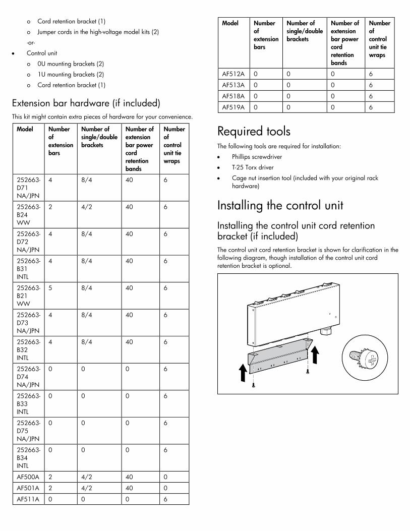
Extension bar hardware (if included) This kit might contain extra pieces of hardware for your convenience.
Model Number of extension bars
Number of single/double brackets
Number of extension bar power cord retention bands
Number of control unit tie wraps
252663-D71 NA/JPN
4 8/4 40 6
252663-B24 WW
2 4/2 40 6
252663-D72 NA/JPN
4 8/4 40 6
252663-B31 INTL
4 8/4 40 6
252663-B21 WW
5 8/4 40 6
252663-D73 NA/JPN
4 8/4 40 6
252663-B32 INTL
4 8/4 40 6
252663-D74 NA/JPN
0 0 0 6
252663-B33 INTL
0 0 0 6
252663-D75 NA/JPN
0 0 0 6
252663-B34 INTL
0 0 0 6
AF500A 2 4/2 40 0
AF501A 2 4/2 40 0
AF511A 0 0 0 6
Model Number of extension bars
Number of single/double brackets
Number of extension bar power cord retention bands
Number of control unit tie wraps
AF512A 0 0 0 6
AF513A 0 0 0 6
AF518A 0 0 0 6
AF519A 0 0 0 6
Required tools The following tools are required for installation:
• Phillips screwdriver
• T-25 Torx driver
• Cage nut insertion tool (included with your original rack hardware)
Installing the control unit Installing the control unit cord retention bracket (if included) The control unit cord retention bracket is shown for clarification in the following diagram, though installation of the control unit cord retention bracket is optional.
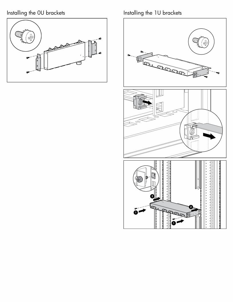
Installing the 0U brackets
Installing the 1U brackets
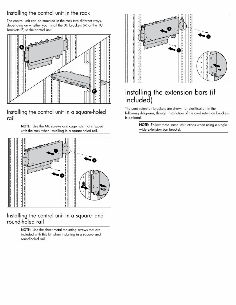
Installing the control unit in the rack The control unit can be mounted in the rack two different ways, depending on whether you install the 0U brackets (A) or the 1U brackets (B) to the control unit.
Installing the control unit in a square-holed rail
NOTE: Use the M6 screws and cage nuts that shipped with the rack when installing in a square-holed rail.
Installing the control unit in a square- and round-holed rail
NOTE: Use the sheet metal mounting screws that are included with this kit when installing in a square- and round-holed rail.
Installing the extension bars (if included) The cord retention brackets are shown for clarification in the following diagrams, though installation of the cord retention brackets is optional.
NOTE: Follow these same instructions when using a single-wide extension bar bracket.
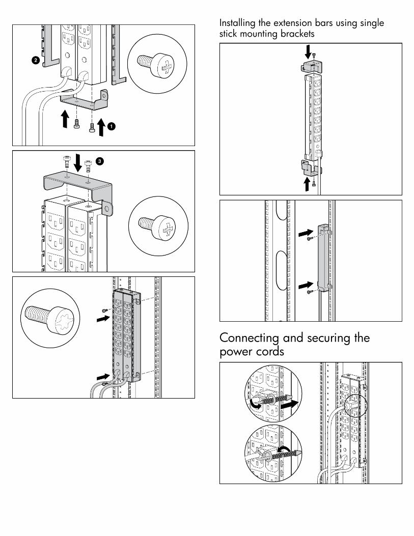
Installing the extension bars using single stick mounting brackets
Connecting and securing the power cords
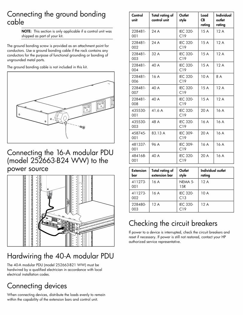
Connecting the ground bonding cable
NOTE: This section is only applicable if a control unit was shipped as part of your kit.
The ground bonding screw is provided as an attachment point for conductors. Use a ground bonding cable if the rack contains any conductors for the purpose of functional grounding or bonding of ungrounded metal parts.
The ground bonding cable is not included in this kit.
Connecting the 16-A modular PDU (model 252663-B24 WW) to the power source
Hardwiring the 40-A modular PDU The 40-A modular PDU (model 252663-B21 WW) must be hardwired by a qualified electrician in accordance with local electrical installation codes.
Connecting devices When connecting devices, distribute the loads evenly to remain within the capability of the extension bars and control unit.
Control unit
Total rating of control unit
Outlet style
Load CB rating
Individual outlet rating
228481-001
24 A IEC 320-C19
15 A 12 A
228481-002
24 A IEC 320-C19
15 A 12 A
228481-003
32 A IEC 320-C19
15 A 12 A
228481-004
40 A IEC 320-C19
15 A 12 A
228481-006
16 A IEC 320-C19
10 A 8 A
228481-007
40 A IEC 320-C19
15 A 12 A
228481-008
40 A IEC 320-C19
15 A 12 A
435530-001
41.6 A IEC 320-C19
20 A 16 A
435530-003
48 A IEC 320-C19
16 A 16 A
458745-001
83.13 A IEC 309-C19
20 A 16 A
481337-001
96 A IEC 309-C19
16 A 16 A
484168-001
40 A IEC 320-C19
20 A 16 A
Extension bar
Total rating of extension bar
Outlet style
Individual outlet rating
411273-001
16 A NEMA 5-15R
12 A
411273-002
16 A IEC 320-C13
10 A
228480-003
12 A IEC 320-C19
12 A
Checking the circuit breakers If power to a device is interrupted, check the circuit breakers and reset if necessary. If power is still not restored, contact your HP authorized service representative.