Embed Size (px)
Citation preview

ISO 9001 2015 MADE IN THE USA
Advanced test equipment for high voltage proof and preventive maintenance testing of electrical apparatus www.hvinc.com
HVI - The World’s Source for
High Voltage Test Equipment
designs and manufactures high voltage test equipment for testing all types of
medium and high voltage equipment used for the Generation, Transmission, and Distribution of
electricity: products for testing substation apparatus, cables, aerial lifts, linemen safety tools, and
a multitude of other loads, including cable fault locating products.
Products range from 3 kV – 600 kV, AC or DC voltage, 1 kVA - 40 kVA, 50/60 Hz. & VLF 0.1 Hz,
parallel resonant systems to 250 kVA, 150 kV & 300 kV AC/DC precision dividers, and high
current neutral & ground cable resistance testers.
HVI leads the world with the finest field test equipment available, the most responsive before,
during, and after sales support, and excellence in service backup, serving over 150 countries
through more than 90 agents since 1997. Always call HVI first.Copyright laws apply

HIGH VOLTAGE TESTING MV CABLECommon Methods for Factory & Field Testing
Monitored
Withstand
VLF TD Test
Monitored
Withstand
VLF PD Test
Partial
Discharge
Destructive vs. Non-DestructiveDiagnostic Testing
Recovery
VoltageIsothermal
Relaxation Current
DC Hipot DC Leakage Current
TDR/Radar
Ω-CHECK® Concentric Neutral Resistance Testing
Online - Offline
So Many Options. What Should I Use?
www.hvinc.com
HIGH VOLTAGE TESTING MV CABLE
FIELD & FACTORY APPLICATIONS
Time to Test
There are a multitude of methods that can be used for
testing power cable to verify operational integrity and to
estimate remaining life. Some are only applicable to
Factory Acceptance testing while others are designed
for Field Acceptance, Installation, & Maintenance
testing. Some are possibly “Destructive” tests while
many are “Non-Destructive Diagnostic” tests. This
presentation will provide a brief look at the various
methods and their technologies used.
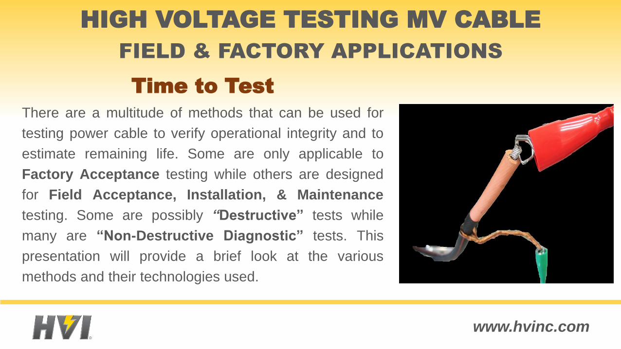
Withstand Tests: Destructive – Pass/Fail – Go/No-Go
The DUT Holds the Test Voltage or Fails
DC Hi-Pot Testing: mostly for PILC cables VLF Hi-Pot Testing AC 50/60 Hz. Hi-Pot Testing
Diagnostic Tests: Non-Destructive
Learn Something of the Insulation Quality
DC Over Voltage Leakage Currents Partial Discharge Testing (PD) Tangent Delta Testing (TD) Recovery Voltage Measurement (RV) Iso Thermal Relaxation Current (IRC)
HIGH VOLTAGE TESTING MV CABLE
Withstand/Proof & Diagnostic Testing
www.hvinc.com
HIGH VOLTAGE TESTING MV CABLE
Withstand/Proof & Diagnostic Testing
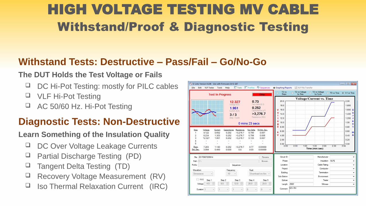
TECHNOLOGIES CURRENTLY AVAILABLE
Simple Dielectric Withstand – AC or DC Voltage
Dielectric Loss (Tan δ & Dielectric Spectroscopy)
Online Partial Discharge (PD)
Offline Partial Discharge (PD)
Isothermal Relaxation Current (IRC)
Recovery Voltage (RV)
Damped AC (DAC) - Oscillating Wave Test Set
www.hvinc.com
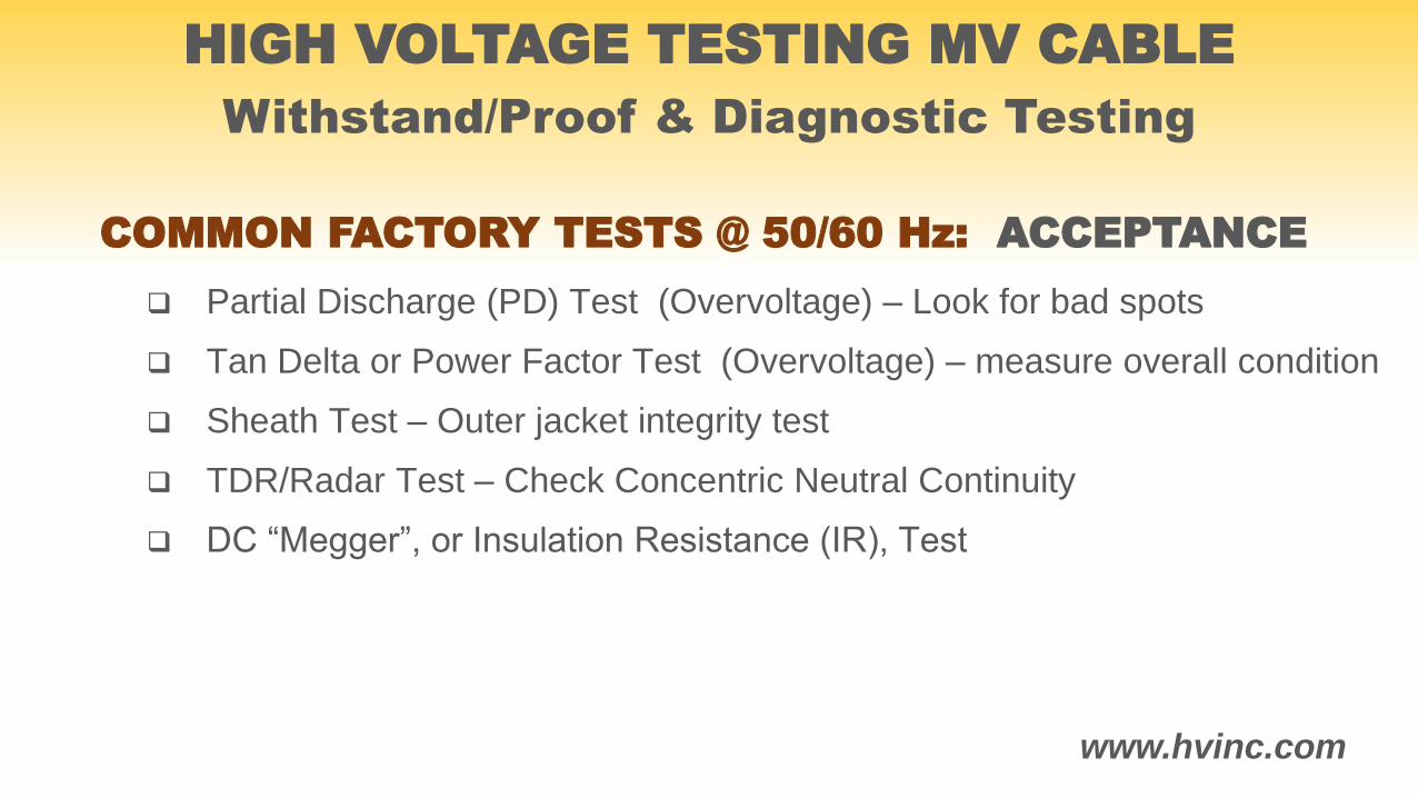
COMMON FACTORY TESTS @ 50/60 Hz: ACCEPTANCE
Partial Discharge (PD) Test (Overvoltage) – Look for bad spots
Tan Delta or Power Factor Test (Overvoltage) – measure overall condition
Sheath Test – Outer jacket integrity test
TDR/Radar Test – Check Concentric Neutral Continuity
DC “Megger”, or Insulation Resistance (IR), Test
HIGH VOLTAGE TESTING MV CABLE
Withstand/Proof & Diagnostic Testing
www.hvinc.com
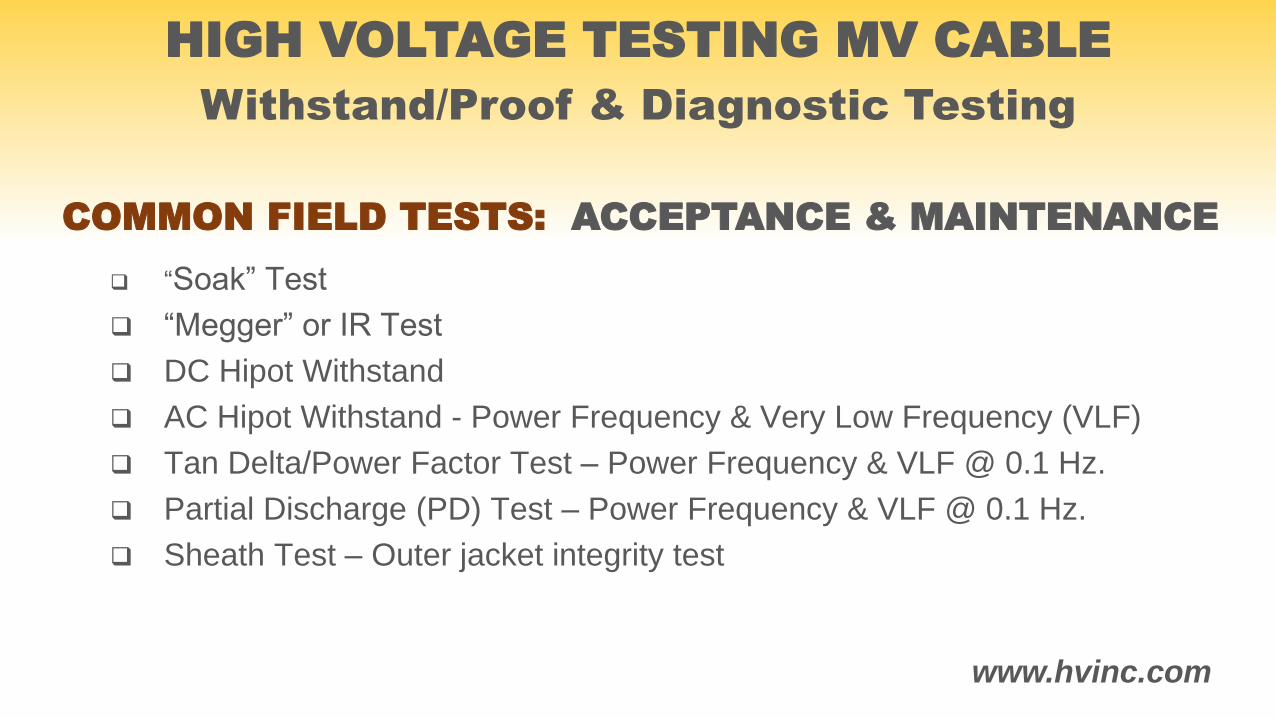
COMMON FIELD TESTS: ACCEPTANCE & MAINTENANCE
“Soak” Test
“Megger” or IR Test
DC Hipot Withstand
AC Hipot Withstand - Power Frequency & Very Low Frequency (VLF)
Tan Delta/Power Factor Test – Power Frequency & VLF @ 0.1 Hz.
Partial Discharge (PD) Test – Power Frequency & VLF @ 0.1 Hz.
Sheath Test – Outer jacket integrity test
HIGH VOLTAGE TESTING MV CABLE
Withstand/Proof & Diagnostic Testing
www.hvinc.com
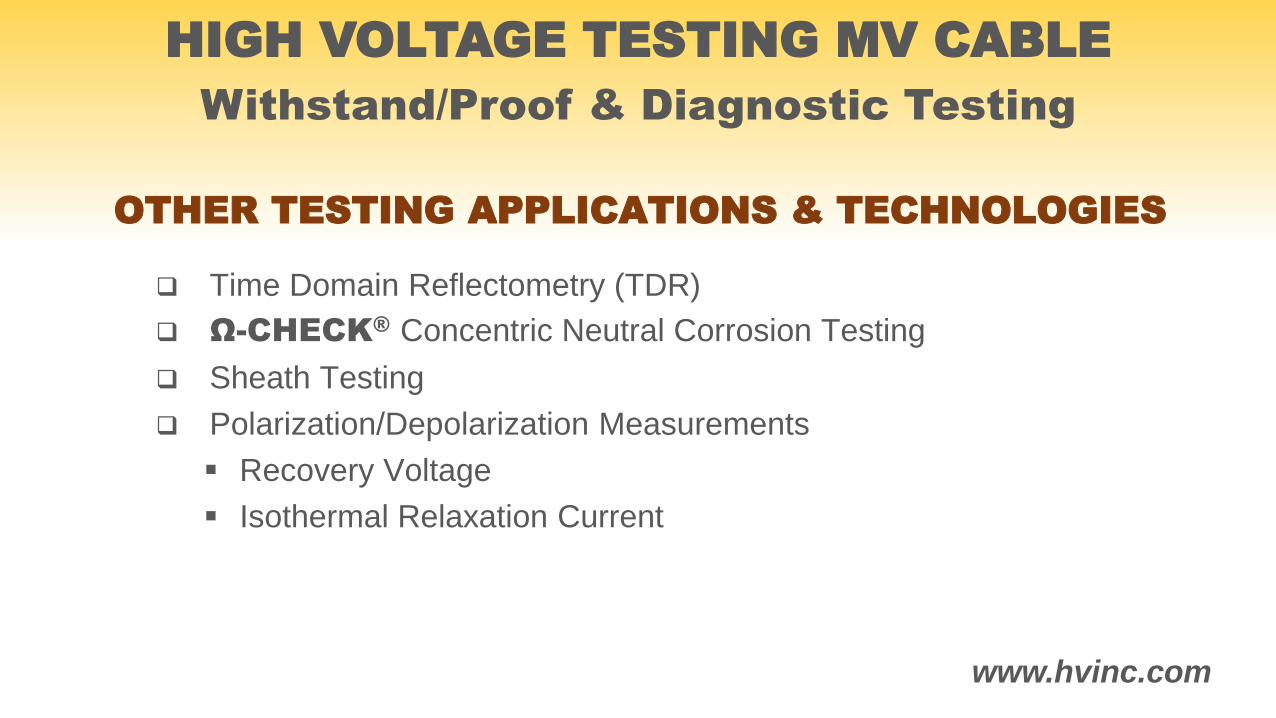
OTHER TESTING APPLICATIONS & TECHNOLOGIES
Time Domain Reflectometry (TDR)
Ω-CHECK® Concentric Neutral Corrosion Testing
Sheath Testing
Polarization/Depolarization Measurements
Recovery Voltage
Isothermal Relaxation Current
HIGH VOLTAGE TESTING MV CABLE
Withstand/Proof & Diagnostic Testing
www.hvinc.com
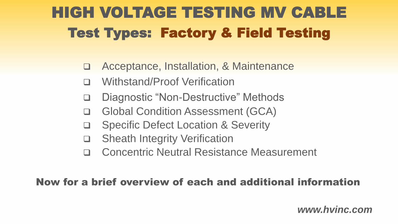
Now for a brief overview of each and additional information
Acceptance, Installation, & Maintenance
Withstand/Proof Verification
Diagnostic “Non-Destructive” Methods
Global Condition Assessment (GCA)
Specific Defect Location & Severity
Sheath Integrity Verification
Concentric Neutral Resistance Measurement
HIGH VOLTAGE TESTING MV CABLE
Test Types: Factory & Field Testing

www.hvinc.com
IEEE 400, the IEEE Guide for Field Testing and Evaluation of the Insulation of Shielded Power
Cable Systems (this is the omnibus guide for other more specific guides such as these listed below.)
IEEE 400.1, the IEEE Guide for Field Testing of Laminated Dielectric, Shielded Power Cable
Systems Rated 5 kV and Above With High Direct Current Voltage
IEEE 400.2, the IEEE Guide for Field Testing of Shielded Power Cable Systems Using Very Low
Frequency (VLF)
IEEE 400.3, the IEEE Guide for Partial Discharge Testing of Power Cable Systems in a Field
Environment
IEEE 400.4, the IEEE Guide for Field Testing of Shielded Power Cable Systems Rated 5 kV and
Above with Damped Alternating Current (DAC) Voltage
IEEE STANDARDS DEFINING MV CABLE TESTS
Above are only the IEEE standards that apply to the various methods of cable testing described, other world standards exist if needed.
HIGH VOLTAGE TESTING MV CABLE
Withstand/Proof & Diagnostic Testing
www.hvinc.com
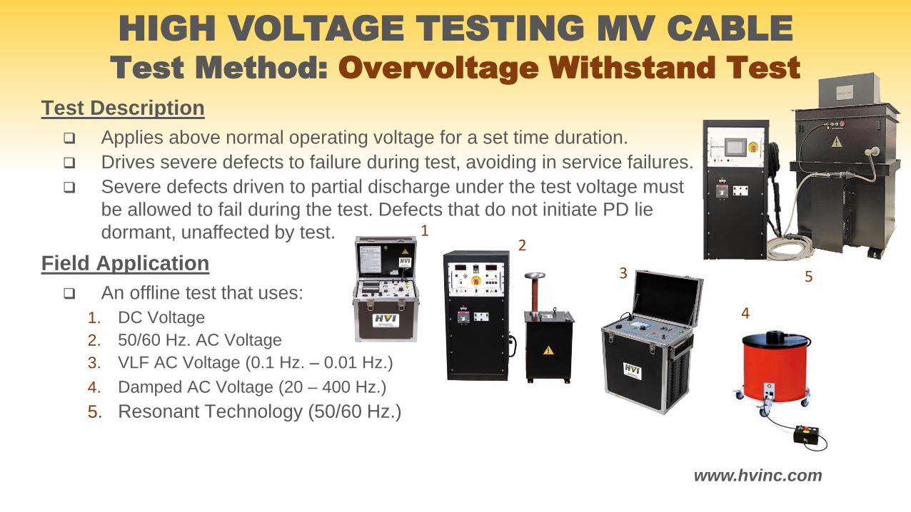
Test Description
Applies above normal operating voltage for a set time duration.
Drives severe defects to failure during test, avoiding in service failures.
Severe defects driven to partial discharge under the test voltage must
be allowed to fail during the test. Defects that do not initiate PD lie
dormant, unaffected by test.
Field Application
An offline test that uses:
1. DC Voltage
2. 50/60 Hz. AC Voltage
3. VLF AC Voltage (0.1 Hz. – 0.01 Hz.)
4. Damped AC Voltage (20 – 400 Hz.)
5. Resonant Technology (50/60 Hz.)
Test Method: Overvoltage Withstand Test
12
3
4
5
HIGH VOLTAGE TESTING MV CABLE
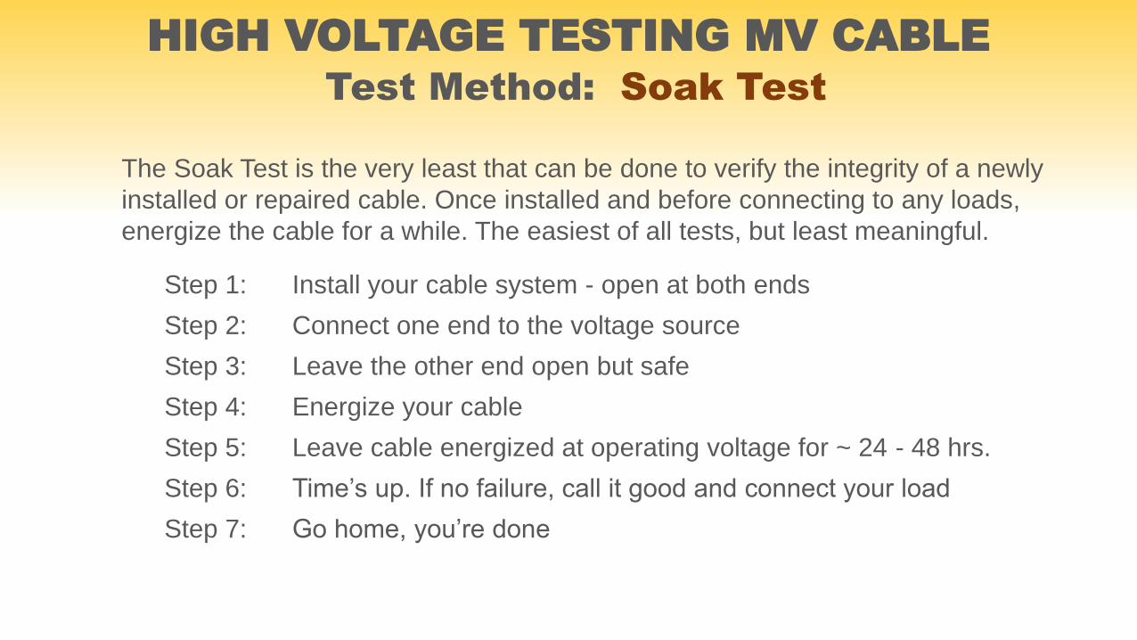
Test Method: Soak Test
The Soak Test is the very least that can be done to verify the integrity of a newly
installed or repaired cable. Once installed and before connecting to any loads,
energize the cable for a while. The easiest of all tests, but least meaningful.
Step 1: Install your cable system - open at both ends
Step 2: Connect one end to the voltage source
Step 3: Leave the other end open but safe
Step 4: Energize your cable
Step 5: Leave cable energized at operating voltage for ~ 24 - 48 hrs.
Step 6: Time’s up. If no failure, call it good and connect your load
Step 7: Go home, you’re done
HIGH VOLTAGE TESTING MV CABLE
www.hvinc.com
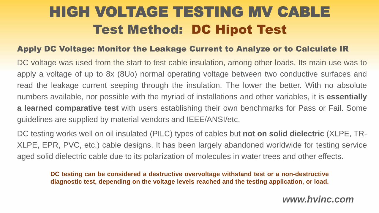
Test Method: DC Hipot Test
Apply DC Voltage: Monitor the Leakage Current to Analyze or to Calculate IR
DC voltage was used from the start to test cable insulation, among other loads. Its main use was to
apply a voltage of up to 8x (8Uo) normal operating voltage between two conductive surfaces and
read the leakage current seeping through the insulation. The lower the better. With no absolute
numbers available, nor possible with the myriad of installations and other variables, it is essentially
a learned comparative test with users establishing their own benchmarks for Pass or Fail. Some
guidelines are supplied by material vendors and IEEE/ANSI/etc.
DC testing works well on oil insulated (PILC) types of cables but not on solid dielectric (XLPE, TR-
XLPE, EPR, PVC, etc.) cable designs. It has been largely abandoned worldwide for testing service
aged solid dielectric cable due to its polarization of molecules in water trees and other effects.
HIGH VOLTAGE TESTING MV CABLE
DC testing can be considered a destructive overvoltage withstand test or a non-destructive
diagnostic test, depending on the voltage levels reached and the testing application, or load.
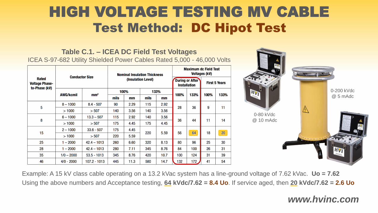
Table C.1. – ICEA DC Field Test VoltagesICEA S-97-682 Utility Shielded Power Cables Rated 5,000 - 46,000 Volts
www.hvinc.com
Example: A 15 kV class cable operating on a 13.2 kVac system has a line-ground voltage of 7.62 kVac. Uo = 7.62
Using the above numbers and Acceptance testing, 64 kVdc/7.62 = 8.4 Uo. If service aged, then 20 kVdc/7.62 = 2.6 Uo
0-80 kVdc
@ 10 mAdc
0-200 kVdc
@ 5 mAdc
Test Method: DC Hipot Test
HIGH VOLTAGE TESTING MV CABLE
Test Method: AC Withstand Test @ 50/60 Hz.
HIGH VOLTAGE TESTING MV CABLE
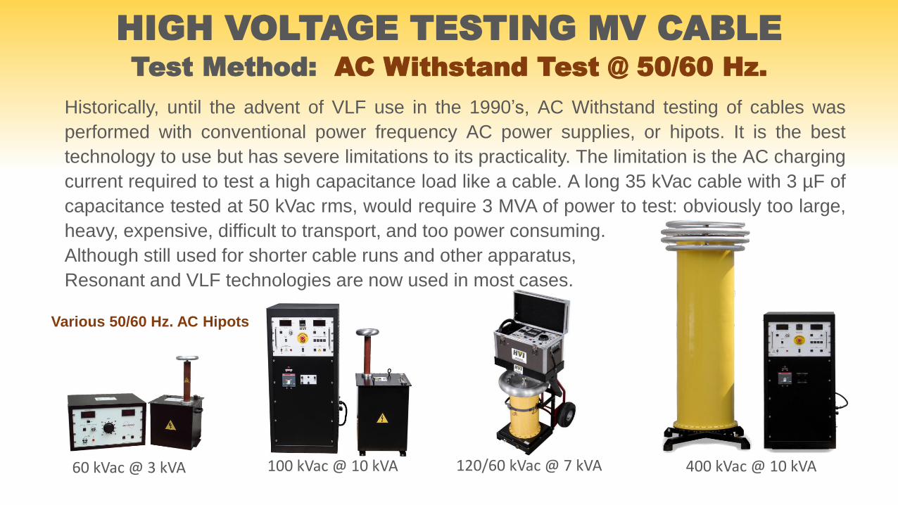
Historically, until the advent of VLF use in the 1990’s, AC Withstand testing of cables was
performed with conventional power frequency AC power supplies, or hipots. It is the best
technology to use but has severe limitations to its practicality. The limitation is the AC charging
current required to test a high capacitance load like a cable. A long 35 kVac cable with 3 µF of
capacitance tested at 50 kVac rms, would require 3 MVA of power to test: obviously too large,
heavy, expensive, difficult to transport, and too power consuming.
Although still used for shorter cable runs and other apparatus,
Resonant and VLF technologies are now used in most cases.
60 kVac @ 3 kVA 100 kVac @ 10 kVA 120/60 kVac @ 7 kVA 400 kVac @ 10 kVA
Various 50/60 Hz. AC Hipots
Test Method: AC Withstand Test @ 50/60 Hz. vs. O.10 Hz.
HIGH VOLTAGE TESTING MV CABLE
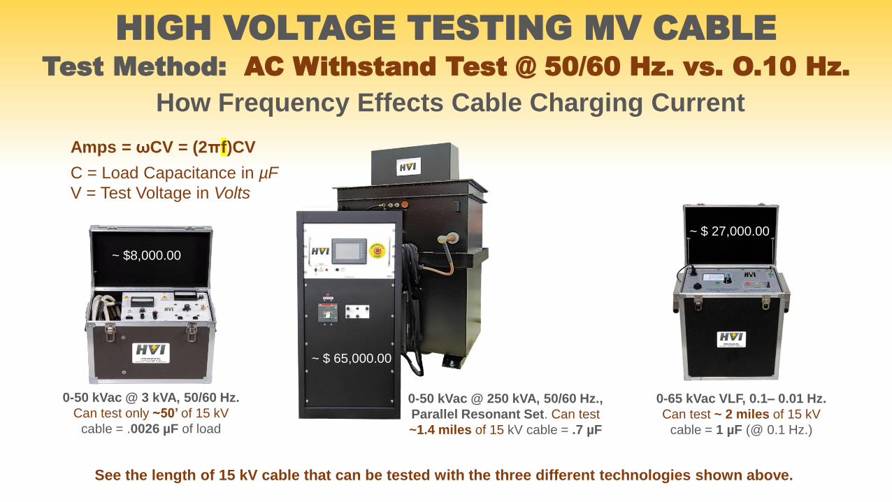
How Frequency Effects Cable Charging Current
Amps = ꞷCV = (2πf)CV
C = Load Capacitance in µF
V = Test Voltage in Volts
See the length of 15 kV cable that can be tested with the three different technologies shown above.
0-65 kVac VLF, 0.1– 0.01 Hz.
Can test ~ 2 miles of 15 kV
cable = 1 µF (@ 0.1 Hz.)
0-50 kVac @ 3 kVA, 50/60 Hz.
Can test only ~50’ of 15 kV
cable = .0026 µF of load
~ $8,000.00
0-50 kVac @ 250 kVA, 50/60 Hz.,
Parallel Resonant Set. Can test
~1.4 miles of 15 kV cable = .7 µF
~ $ 65,000.00
~ $ 27,000.00
Test Method: Series/Parallel Resonant Technology
HIGH VOLTAGE TESTING MV CABLE
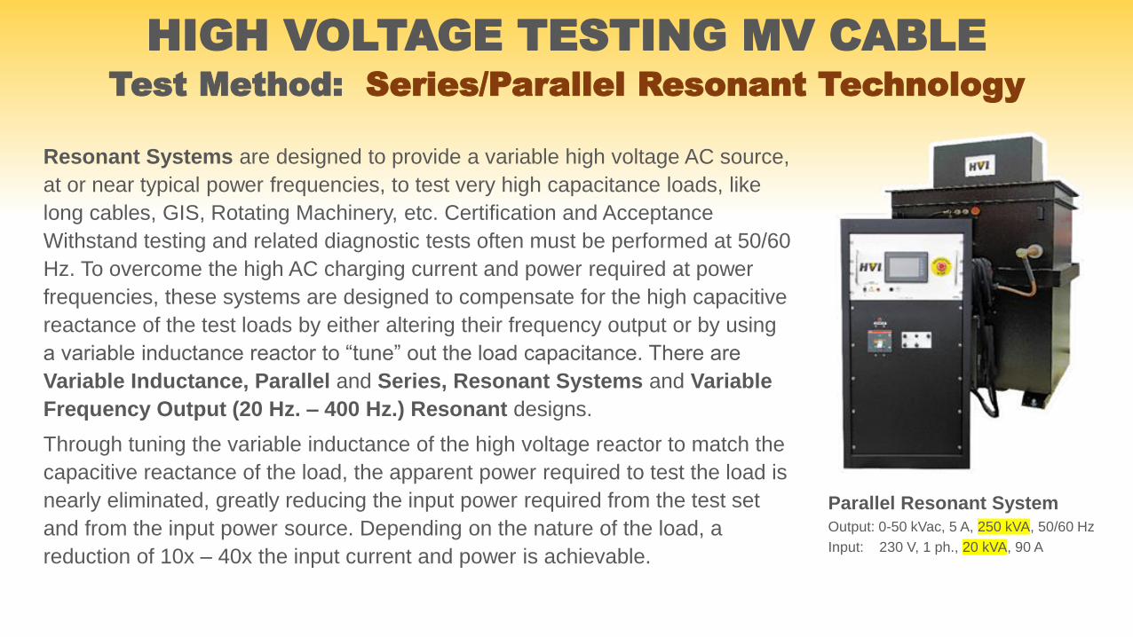
Resonant Systems are designed to provide a variable high voltage AC source,
at or near typical power frequencies, to test very high capacitance loads, like
long cables, GIS, Rotating Machinery, etc. Certification and Acceptance
Withstand testing and related diagnostic tests often must be performed at 50/60
Hz. To overcome the high AC charging current and power required at power
frequencies, these systems are designed to compensate for the high capacitive
reactance of the test loads by either altering their frequency output or by using
a variable inductance reactor to “tune” out the load capacitance. There are
Variable Inductance, Parallel and Series, Resonant Systems and Variable
Frequency Output (20 Hz. – 400 Hz.) Resonant designs.
Through tuning the variable inductance of the high voltage reactor to match the
capacitive reactance of the load, the apparent power required to test the load is
nearly eliminated, greatly reducing the input power required from the test set
and from the input power source. Depending on the nature of the load, a
reduction of 10x – 40x the input current and power is achievable.
Parallel Resonant System
Output: 0-50 kVac, 5 A, 250 kVA, 50/60 Hz
Input: 230 V, 1 ph., 20 kVA, 90 A
Test Method: Series/Parallel Resonant Technology
HIGH VOLTAGE TESTING MV CABLE
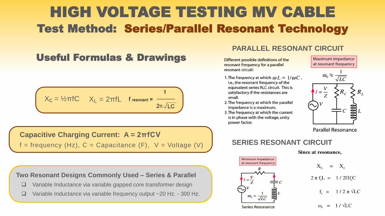
Capacitive Charging Current: A = 2πfCV
f = frequency (Hz), C = Capacitance (F), V = Voltage (V)
XL = 2πfLXc = ½πfC
Useful Formulas & Drawings
Two Resonant Designs Commonly Used – Series & Parallel
Variable Inductance via variable gapped core transformer design
Variable Inductance via variable frequency output ~20 Hz. - 300 Hz.
PARALLEL RESONANT CIRCUIT
SERIES RESONANT CIRCUIT
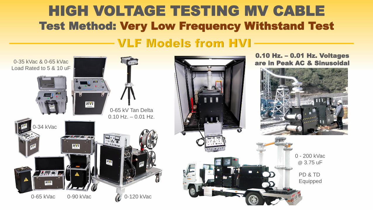
Test Method: Very Low Frequency Withstand Test
HIGH VOLTAGE TESTING MV CABLE
0.10 Hz. – 0.01 Hz. Voltages
are in Peak AC & Sinusoidal
0-65 kVac 0-90 kVac 0-120 kVac
0-35 kVac & 0-65 kVac
Load Rated to 5 & 10 uF
0-65 kV Tan Delta
0.10 Hz. – 0.01 Hz.
0 - 200 kVac
@ 3.75 uF
0-34 kVac
PD & TD
Equipped
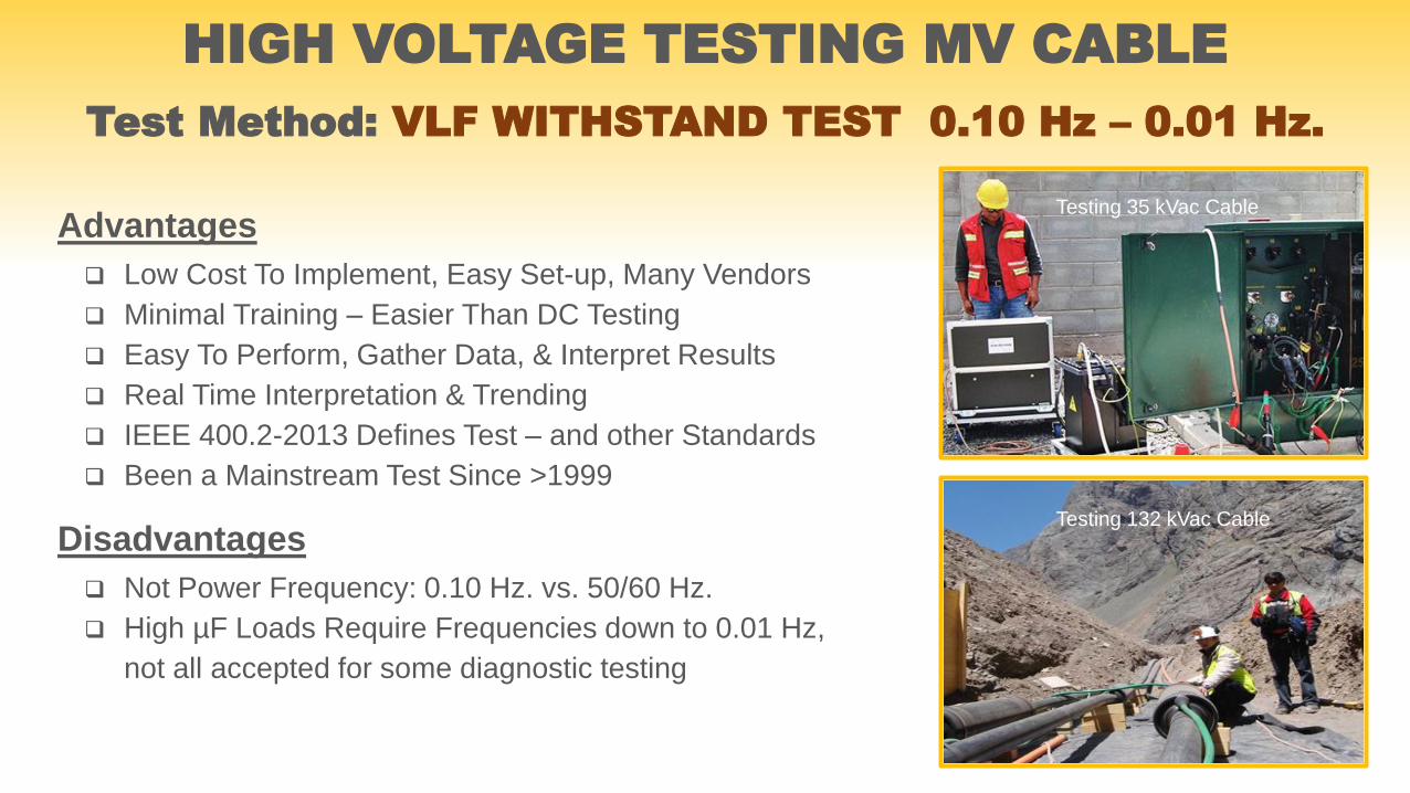
Test Method: VLF WITHSTAND TEST 0.10 Hz – 0.01 Hz.
Advantages
Low Cost To Implement, Easy Set-up, Many Vendors
Minimal Training – Easier Than DC Testing
Easy To Perform, Gather Data, & Interpret Results
Real Time Interpretation & Trending
IEEE 400.2-2013 Defines Test – and other Standards
Been a Mainstream Test Since >1999
Disadvantages
Not Power Frequency: 0.10 Hz. vs. 50/60 Hz.
High µF Loads Require Frequencies down to 0.01 Hz,
not all accepted for some diagnostic testing
HIGH VOLTAGE TESTING MV CABLE
Testing 35 kVac Cable
Testing 132 kVac Cable

Global Cable Assessment (GCA) Evaluation
GCA tests assess the overall health of the cable insulation.
These tests include DF/tan δ/PF, PD, Dielectric Spectroscopy,
Depolarization: Recovery Voltage and Isothermal Relaxation
Current. Each of these tests have their place and their
advantages and disadvantages. Several of the more common
tests performed will be explained in the slides ahead.
HIGH VOLTAGE TESTING MV CABLE
DIAGNOSTIC NON-DESTRUCTIVE TESTING
Often, we just want to know the general condition of a group of cables and don’t want to
hipot the cables and risk failures. Non-Destructive Diagnostic Testing is what we want.
HIGH VOLTAGE TESTING MV CABLE
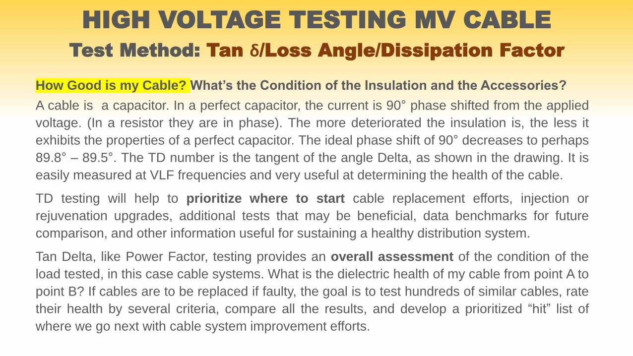
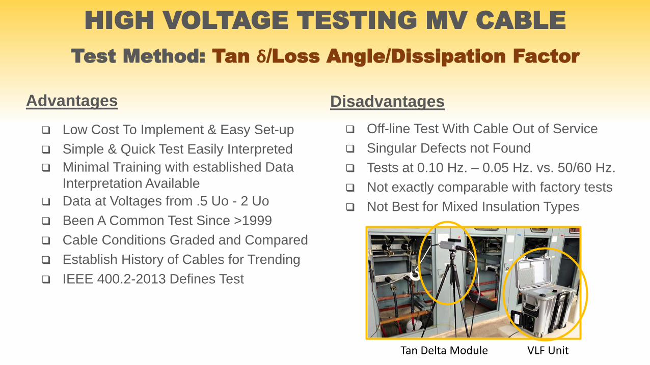
Test Method: Tan ẟ/Loss Angle/Dissipation Factor
How Good is my Cable? What’s the Condition of the Insulation and the Accessories?
A cable is a capacitor. In a perfect capacitor, the current is 90° phase shifted from the applied
voltage. (In a resistor they are in phase). The more deteriorated the insulation is, the less it
exhibits the properties of a perfect capacitor. The ideal phase shift of 90° decreases to perhaps
89.8° – 89.5°. The TD number is the tangent of the angle Delta, as shown in the drawing. It is
easily measured at VLF frequencies and very useful at determining the health of the cable.
TD testing will help to prioritize where to start cable replacement efforts, injection or
rejuvenation upgrades, additional tests that may be beneficial, data benchmarks for future
comparison, and other information useful for sustaining a healthy distribution system.
Tan Delta, like Power Factor, testing provides an overall assessment of the condition of the
load tested, in this case cable systems. What is the dielectric health of my cable from point A to
point B? If cables are to be replaced if faulty, the goal is to test hundreds of similar cables, rate
their health by several criteria, compare all the results, and develop a prioritized “hit” list of
where we go next with cable system improvement efforts.
HIGH VOLTAGE TESTING MV CABLE
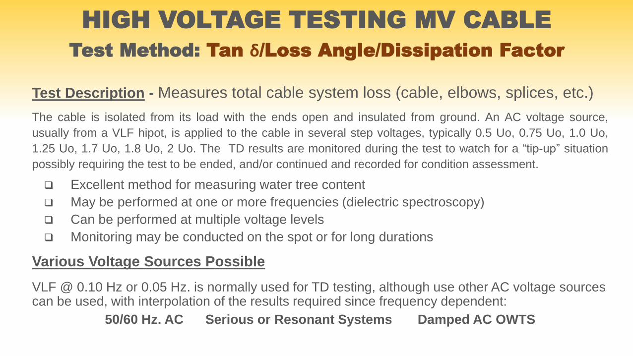
Test Method: Tan ẟ/Loss Angle/Dissipation Factor
Test Description - Measures total cable system loss (cable, elbows, splices, etc.)
The cable is isolated from its load with the ends open and insulated from ground. An AC voltage source,
usually from a VLF hipot, is applied to the cable in several step voltages, typically 0.5 Uo, 0.75 Uo, 1.0 Uo,
1.25 Uo, 1.7 Uo, 1.8 Uo, 2 Uo. The TD results are monitored during the test to watch for a “tip-up” situation
possibly requiring the test to be ended, and/or continued and recorded for condition assessment.
Excellent method for measuring water tree content
May be performed at one or more frequencies (dielectric spectroscopy)
Can be performed at multiple voltage levels
Monitoring may be conducted on the spot or for long durations
Various Voltage Sources Possible
VLF @ 0.10 Hz or 0.05 Hz. is normally used for TD testing, although use other AC voltage sources can be used, with interpolation of the results required since frequency dependent:
50/60 Hz. AC Serious or Resonant Systems Damped AC OWTS

HIGH VOLTAGE TESTING MV CABLETest Method: Tan ẟ/Loss Angle/Dissipation Factor
Tan ẟ = IR/IC = 1/ꞷRC
Example of Test: 15 kV (rms) System Voltage
VLF-TD Interpretation
TD Stability - TD vs. Voltage - Absolute Value - Trend
Test Method: Tan ẟ/Loss Angle/Dissipation Factor
HIGH VOLTAGE TESTING MV CABLE
Advantages
Low Cost To Implement & Easy Set-up
Simple & Quick Test Easily Interpreted
Minimal Training with established Data
Interpretation Available
Data at Voltages from .5 Uo - 2 Uo
Been A Common Test Since >1999
Cable Conditions Graded and Compared
Establish History of Cables for Trending
IEEE 400.2-2013 Defines Test
Disadvantages
Off-line Test With Cable Out of Service
Singular Defects not Found
Tests at 0.10 Hz. – 0.05 Hz. vs. 50/60 Hz.
Not exactly comparable with factory tests
Not Best for Mixed Insulation Types
Tan Delta Module VLF Unit
Partial Discharge (PD) testing is a “diagnostic” test used to
assess the condition of a cable's insulation system, searching
for any problems or defects within insulation itself, terminations,
joints, splices, etc. It attempts to locate and measure the
severity of any PD event in the cable. PD testing can be
performed both “on-line” during a U0 Soak Test or while load
energized, or “off-line” during an overvoltage AC Hipot test at
various frequencies, usually VLF when field testing.
HIGH VOLTAGE TESTING MV CABLETest Method: Partial Discharge
Test Description
An over voltage test to stress cable system to look for PD producing defects.
Measurement and interpretation of partial discharge signals below and above normal
operating voltages are made. Magnitude, location, and inception & extinction
voltages are all important indictors of cable condition.
Field Application
Apply high voltage to de-energized and disconnected cable up to pre-determined
level while observing the results, to stop test or voltage increase if necessary, to
prevent failure if PD is present. Record test data for later analysis. It is an Off-line
test that can use:
50/60 Hz. AC, conventional hipot or resonant
VLF AC @ 0.10 Hz. – 0.05 Hz.
Damped AC @ 20 Hz. – 500 Hz.
HIGH VOLTAGE TESTING MV CABLETest Method: Partial Discharge - Offline

Your Pre-Test List of Items & Actions Needed
A Cable Map
A TDR/Radar to Map Out Cable
Know your Cable Lengths
Know the Splice Locations
Know Cable’s Propagation Velocity
Perform a Sensitivity Check by
Injecting a 0.5, 1, or 2 nC signal
Verify TDR info
HIGH VOLTAGE TESTING MV CABLETest Method: Partial Discharge Offline Setup
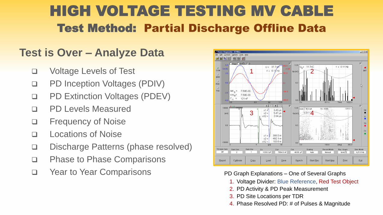
Test is Over – Analyze Data
Voltage Levels of Test
PD Inception Voltages (PDIV)
PD Extinction Voltages (PDEV)
PD Levels Measured
Frequency of Noise
Locations of Noise
Discharge Patterns (phase resolved)
Phase to Phase Comparisons
Year to Year Comparisons
HIGH VOLTAGE TESTING MV CABLETest Method: Partial Discharge Offline Data
PD Graph Explanations – One of Several Graphs
1. Voltage Divider: Blue Reference, Red Test Object
2. PD Activity & PD Peak Measurement
3. PD Site Locations per TDR
4. Phase Resolved PD: # of Pulses & Magnitude
1 2
3 4

HIGH VOLTAGE TESTING MV CABLETest Method: Partial Discharge Offline Data
VLF Hipot PD/TD Filtering/Measurement Capacitors & Detectors
Signal Input & Interpretation & Laptop w/Operating Software & Data Logging
Cable Load Tested
The Equipment Needed & the Setup
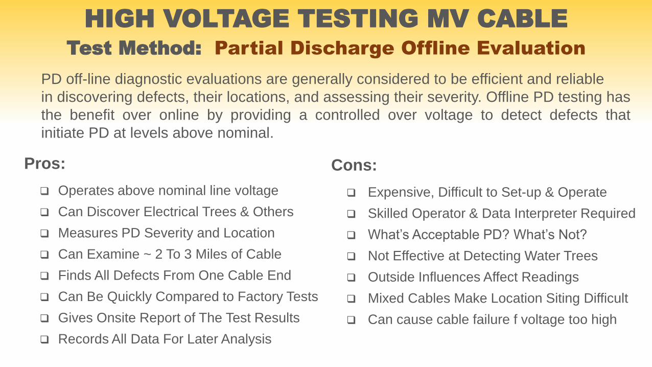
Pros:
Operates above nominal line voltage
Can Discover Electrical Trees & Others
Measures PD Severity and Location
Can Examine ~ 2 To 3 Miles of Cable
Finds All Defects From One Cable End
Can Be Quickly Compared to Factory Tests
Gives Onsite Report of The Test Results
Records All Data For Later Analysis
Cons:
Expensive, Difficult to Set-up & Operate
Skilled Operator & Data Interpreter Required
What’s Acceptable PD? What’s Not?
Not Effective at Detecting Water Trees
Outside Influences Affect Readings
Mixed Cables Make Location Siting Difficult
Can cause cable failure f voltage too high
PD off-line diagnostic evaluations are generally considered to be efficient and reliable
in discovering defects, their locations, and assessing their severity. Offline PD testing has
the benefit over online by providing a controlled over voltage to detect defects that
initiate PD at levels above nominal.
HIGH VOLTAGE TESTING MV CABLETest Method: Partial Discharge Offline Evaluation
HIGH VOLTAGE TESTING MV CABLETest Method: Monitored Withstand TD & PD
How does the word “Monitor” in the name fit in?
While we are performing a 30 - 60 minute VLF Withstand test, let’s do something more while we wait.
What other tests can we do during that time that would be valuable for diagnosing the cable quality?
Since we have 2 – 3 times normal operating voltage on the cable for the hipot test, let’s also measure
and record the Tan Delta numbers and/or the Partial Discharge activity. The TD and PD data saved
over a long test period is valuable information in diagnosing the insulation and accessories quality.
Since the intent of TD and PD testing is to be non-destructive (no failed cables during the test) then an
important part of the test is to “Monitor” the numbers of each as we increase the test voltage in steps
from zero to maximum while we observe the TD and PD data along the way. If all looks good at step
1, then we will advance to step 2, and so on. We will Monitor the data this way until we reach the
maximum test voltage set by the Standards for VLF Withstand testing (which is higher than the normal
levels for TD and PD). If we see dangerous PD levels or severe “tip-ups” to the TD numbers, then we
can stop the test to avoid a failure. We have learned what we came for about the cable.
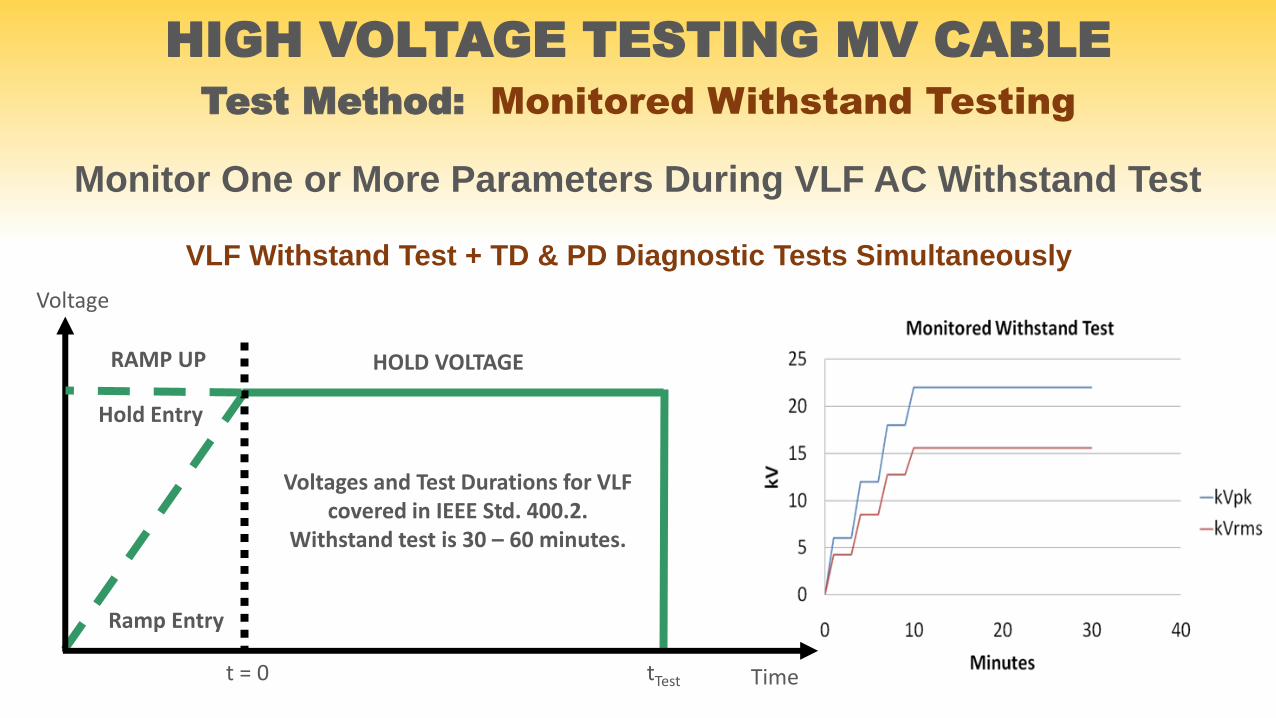
HOLD VOLTAGERAMP UP
Time
Voltage
t = 0 tTest
Voltages and Test Durations for VLF covered in IEEE Std. 400.2.
Withstand test is 30 – 60 minutes.
Hold Entry
Ramp Entry
VLF Withstand Test + TD & PD Diagnostic Tests Simultaneously
Monitor One or More Parameters During VLF AC Withstand Test
HIGH VOLTAGE TESTING MV CABLE
Test Method: Monitored Withstand Testing
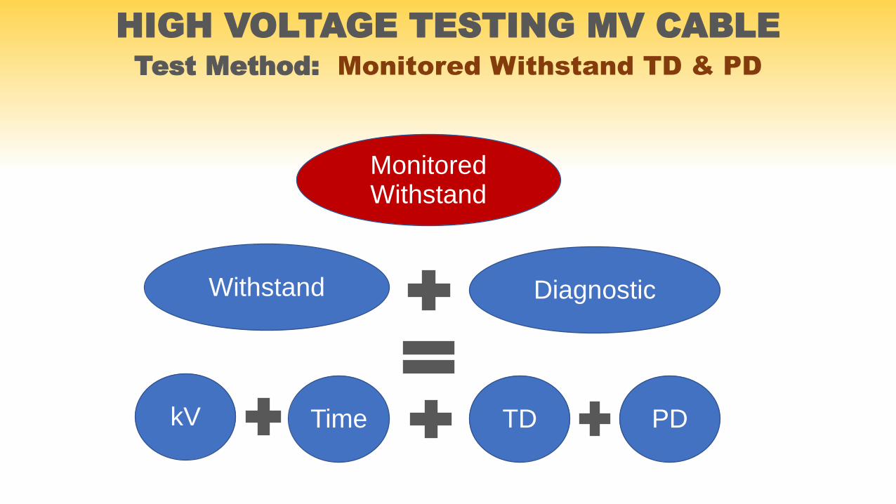
HIGH VOLTAGE TESTING MV CABLETest Method: Monitored Withstand TD & PD
Monitored Withstand
Diagnostic
TD
Withstand
PDkV Time
HIGH VOLTAGE TESTING MV CABLETest Method: Damped AC PD Measurement (OWTS)
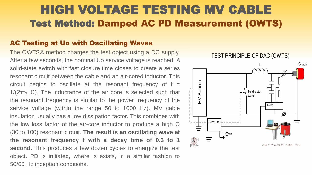
AC Testing at Uo with Oscillating Waves
The OWTS® method charges the test object using a DC supply.
After a few seconds, the nominal Uo service voltage is reached. A
solid-state switch with fast closure time closes to create a series
resonant circuit between the cable and an air-cored inductor. This
circuit begins to oscillate at the resonant frequency of f =
1/(2π√LC). The inductance of the air core is selected such that
the resonant frequency is similar to the power frequency of the
service voltage (within the range 50 to 1000 Hz). MV cable
insulation usually has a low dissipation factor. This combines with
the low loss factor of the air-core inductor to produce a high Q
(30 to 100) resonant circuit. The result is an oscillating wave at
the resonant frequency f with a decay time of 0.3 to 1
second. This produces a few dozen cycles to energize the test
object. PD is initiated, where is exists, in a similar fashion to
50/60 Hz inception conditions.
www.hvinc.com
HIGH VOLTAGE TESTING MV CABLETest Method: Damped AC PD Measurement (OWTS)
OWTS Features & Test Results
PD diagnosis under oscillating wave test voltage – electrical field distribution as in nominal
service conditions
PD level measurement according to IEC 270 at a bandwidth of 150 … 650 kHz
Automatic Calibration and Joint location facility
Semi and fully automatic PD analyzing software for defect location with mapping feature
Calculation of the cable capacitance and the tan delta value of the test object from the
characteristic decrease of the voltage wave shape
Simple to use and easy to handle menu-driven unit for operation of the test sequence
Compact design, low weight
www.hvinc.com
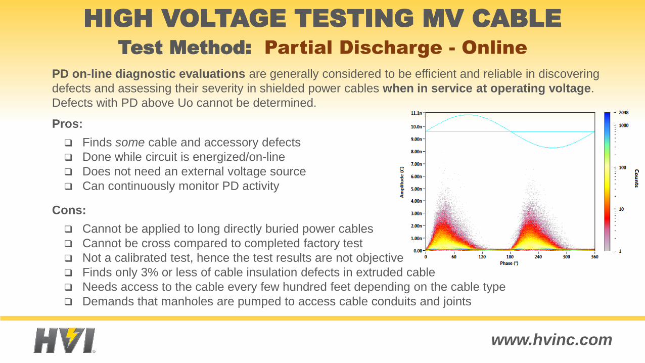
Pros:
Finds some cable and accessory defects
Done while circuit is energized/on-line
Does not need an external voltage source
Can continuously monitor PD activity
Cons:
Cannot be applied to long directly buried power cables
Cannot be cross compared to completed factory test
Not a calibrated test, hence the test results are not objective
Finds only 3% or less of cable insulation defects in extruded cable
Needs access to the cable every few hundred feet depending on the cable type
Demands that manholes are pumped to access cable conduits and joints
PD on-line diagnostic evaluations are generally considered to be efficient and reliable in discovering
defects and assessing their severity in shielded power cables when in service at operating voltage.
Defects with PD above Uo cannot be determined.
HIGH VOLTAGE TESTING MV CABLETest Method: Partial Discharge - Online
www.hvinc.com
Polarization and Depolarization Currents Measurement
A cable is essentially a capacitor; the conductor is one plate and the neutral is the other, with the
insulation acting as the dielectric material. The charging and discharging characteristics of a capacitor are
well known, under both AC and DC voltage environments. The more imperfect the cable insulation, the
more its behavior deviates from a pure capacitor. By measuring, grading, and comparing test results vs.
ideal data, the quality of the insulation can be determined. Several methods employing this principle
provide an overall, or global, assessment of the insulation over the entire cable length, detecting the
presence of water trees, physical defects, and any conductive types of defects.
There are several methods of looking at the response of the insulation during its discharge. These tests all
examine the polarization behavior of the insulation, due primarily to moisture content. However, since all
three current modes (absorbtion, capacitive charging, & leakage) are present during the charging phase
of an insulation test, the measure of absorption current is difficult since masked by the presence of the
higher capacitive and leakage currents. The discharge phase of the test can more rapidly remove these
effects, giving the possibility of interpreting the degree of polarization of the insulation and relating this to
moisture and other polarization effects.
HIGH VOLTAGE TESTING MV CABLETest Method: Dielectric Response Analysis
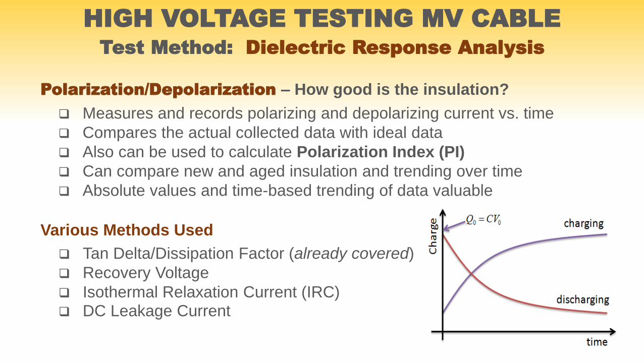
Various Methods Used
Tan Delta/Dissipation Factor (already covered)
Recovery Voltage
Isothermal Relaxation Current (IRC) DC Leakage Current
HIGH VOLTAGE TESTING MV CABLETest Method: Dielectric Response Analysis
Polarization/Depolarization – How good is the insulation?
Measures and records polarizing and depolarizing current vs. time
Compares the actual collected data with ideal data
Also can be used to calculate Polarization Index (PI)
Can compare new and aged insulation and trending over time
Absolute values and time-based trending of data valuable
www.hvinc.com
Recovery Voltage Method
This test is used to determine the level of water tree degradation and other impurities
in extruded insulation. Like other cable insulation diagnostic tests, it relies on the
known principles of the charging and discharging characteristics of capacitance,
comparing the ideal behavior versus that of the tested cable.
DC voltage is used to charge the cable. The cable is then discharged to ground
through a resistor. The ground is lifted, and the cable rebuilds a charge. This rising
open circuit voltage is recorded, graphed against time, and then compared to the
charging wave shape of a perfect capacitor. The more imperfections in the insulation
the more it will deviate from the ideal.
HIGH VOLTAGE TESTING MV CABLETest Method: Dielectric Response Analysis

www.hvinc.com
Recovery Voltage Method
Cable is charged with DC voltage for a short time
Cable discharged with ground resistor then ground removed
Open circuit voltage climb recorded & mapped versus time
Curve shape data indicates moisture in PILC cables
Curve shape data indicates water tree extent in solid dielectric
HIGH VOLTAGE TESTING MV CABLETest Method: Dielectric Response Analysis

www.hvinc.com
Isothermal Relaxation Current IRC
HIGH VOLTAGE TESTING MV CABLETest Method: Dielectric Response Analysis
IRC Analysis offers a non-destructive method of
measuring and analyzing the degradation processes of
polymeric composites. This diagnostic method provides a
global statement about the quality of the insulation. It is
based on the measurement of the depolarization current
after previous charging with DC voltage. Different rates of
relaxation current with respect to time are determined and
represented in an IRC-Diagram. For the best results, it
requires a reference value from the past to show the
changes in the condition of the insulation.
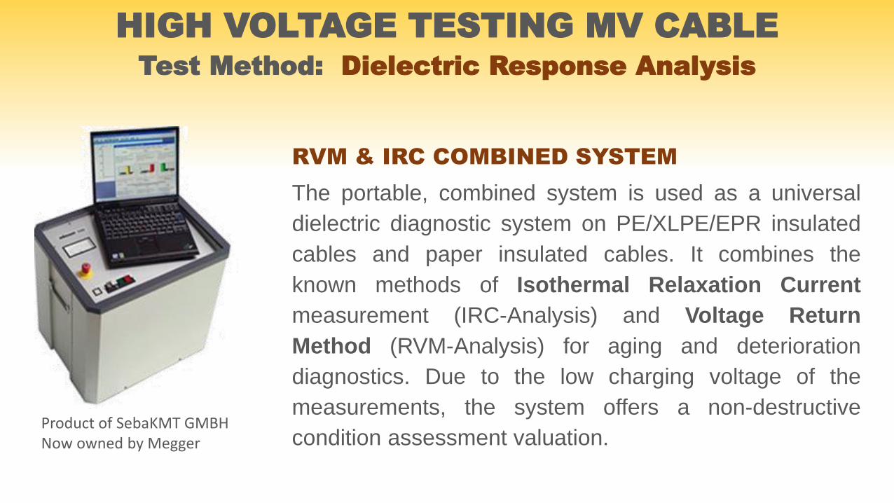
RVM & IRC COMBINED SYSTEM
The portable, combined system is used as a universal
dielectric diagnostic system on PE/XLPE/EPR insulated
cables and paper insulated cables. It combines the
known methods of Isothermal Relaxation Current
measurement (IRC-Analysis) and Voltage Return
Method (RVM-Analysis) for aging and deterioration
diagnostics. Due to the low charging voltage of the
measurements, the system offers a non-destructive
condition assessment valuation.Product of SebaKMT GMBH Now owned by Megger
HIGH VOLTAGE TESTING MV CABLETest Method: Dielectric Response Analysis
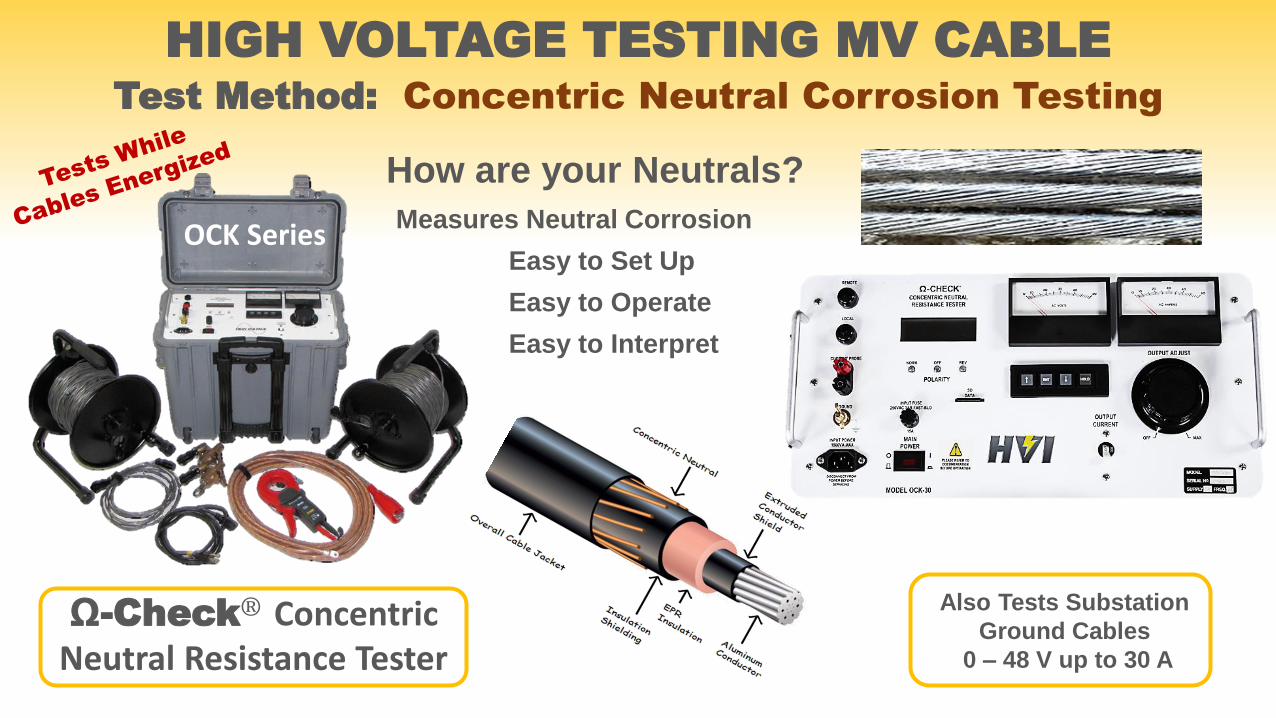
How are your Neutrals?
Measures Neutral Corrosion
Easy to Set Up
Easy to Operate
Easy to Interpret
OCK Series
HIGH VOLTAGE TESTING MV CABLETest Method: Concentric Neutral Corrosion Testing
Ω-Check® Concentric Neutral Resistance Tester
Also Tests Substation
Ground Cables
0 – 48 V up to 30 A

CONCENTRIC NEUTRAL CORROSION TESTING
How Many Neutral Strands Do You Have Left?
The HVIΩ-CHECK®
Test Neutrals
With Cable
Energized
Can you answer these questions?How many neutral strands are open? Where is my return current going?
Where is my fault current going? Why is my ground at elevated voltage?
Healthy neutrals are vital to the stability, reliability, and safety of any distribution
or transmission system. All the above are definite problems if much of the
concentric neutral is missing. Here are some of the potential problems if
neutrals corrode:
Injecting or rejuvenating cables? First measure the neutrals
to insure enough remain before the effort & expense of injecting.
Partial Discharge or Tan Delta testing your cables? What good are
the results if your neutral is missing?
Unexplained voltage fluctuations and shock hazards on metal fixtures
or in swimming pools?
URD return currents paths not going where they should, causing relay
protection and control problems?
Severe shock hazards, fires, or explosions? Fault currents jumping to
other utilities or pipes?
Don’t ignore the health of your neutrals. There is a way to conveniently
measure the resistance of the neutral, compare it to what it should be, and
display and store the results. It’s easy, quick, and economical.
HIGH VOLTAGE TESTING MV CABLETest Method: SHEATH TESTING
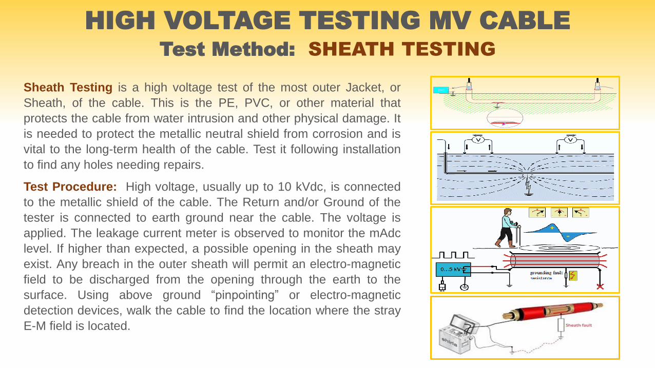
Sheath Testing is a high voltage test of the most outer Jacket, or
Sheath, of the cable. This is the PE, PVC, or other material that
protects the cable from water intrusion and other physical damage. It
is needed to protect the metallic neutral shield from corrosion and is
vital to the long-term health of the cable. Test it following installation
to find any holes needing repairs.
Test Procedure: High voltage, usually up to 10 kVdc, is connected
to the metallic shield of the cable. The Return and/or Ground of the
tester is connected to earth ground near the cable. The voltage is
applied. The leakage current meter is observed to monitor the mAdc
level. If higher than expected, a possible opening in the sheath may
exist. Any breach in the outer sheath will permit an electro-magnetic
field to be discharged from the opening through the earth to the
surface. Using above ground “pinpointing” or electro-magnetic
detection devices, walk the cable to find the location where the stray
E-M field is located.
www.hvinc.com
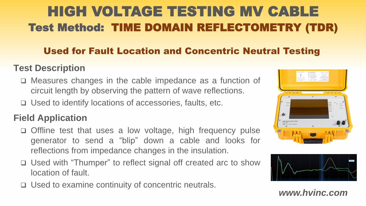
Test Description
Measures changes in the cable impedance as a function of
circuit length by observing the pattern of wave reflections.
Used to identify locations of accessories, faults, etc.
Field Application
Offline test that uses a low voltage, high frequency pulse
generator to send a “blip” down a cable and looks for
reflections from impedance changes in the insulation.
Used with “Thumper” to reflect signal off created arc to show
location of fault.
Used to examine continuity of concentric neutrals.
HIGH VOLTAGE TESTING MV CABLETest Method: TIME DOMAIN REFLECTOMETRY (TDR)
Used for Fault Location and Concentric Neutral Testing

TECHNOLOGIES CURRENTLY CONSIDERED
Dielectric Loss (Tan δ & Dielectric Spectroscopy)
DC Voltage Hipot
Insulation Resistance (IR) Test
Online Partial Discharge (PD)
Offline Partial Discharge (PD)
VLF Monitored Withstand Tan Delta (MWTD)
VLF Monitored Withstand Partial Discharge (MWPD)
Isothermal Relaxation Current (IRC)
Recovery Voltage (RV)
Damped AC (DAC) – Oscillating Wave Tester
Time Domain Reflectometry (TDR)
HIGH VOLTAGE TESTING MV CABLE
REVIEW: DIAGNOSTIC TESTS PRESENTED

HIGH VOLTAGE TESTING MV CABLETest Method: Cable Fault Locating
….and then come the cable faults, many cable faults!
What to do?
1. ID the faulted cable or cables
2. Find the faults: insulation & accessories
3. Fix the faults or replace what's bad
4. Over voltage test the repaired cable
5. Verify no other faults were created
6. Verify the adjacent cables are not harmed
7. Re-energize and maybe perform on-line tests
8. Clean and pull maintenance on the equipment
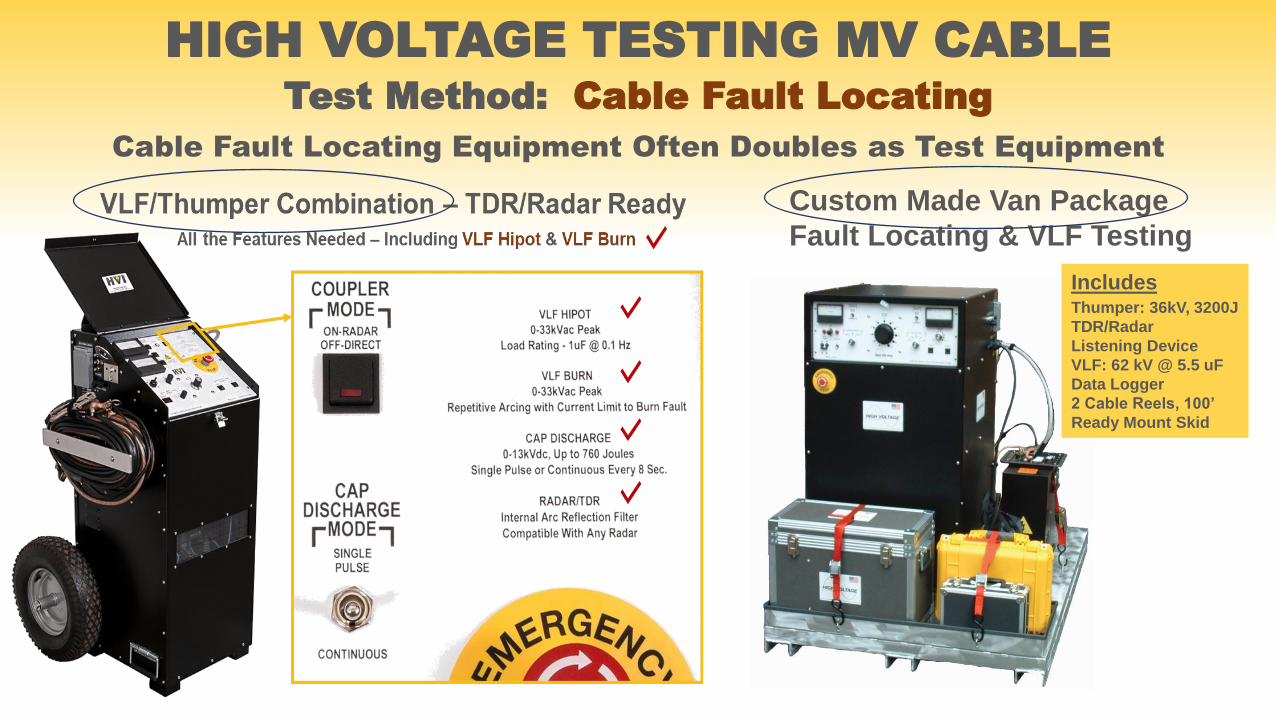
HIGH VOLTAGE TESTING MV CABLETest Method: Cable Fault Locating
Cable Fault Locating Equipment Often Doubles as Test Equipment
Custom Made Van Package
Fault Locating & VLF Testing
IncludesThumper: 36kV, 3200J
TDR/Radar
Listening Device
VLF: 62 kV @ 5.5 uF
Data Logger
2 Cable Reels, 100’
Ready Mount Skid
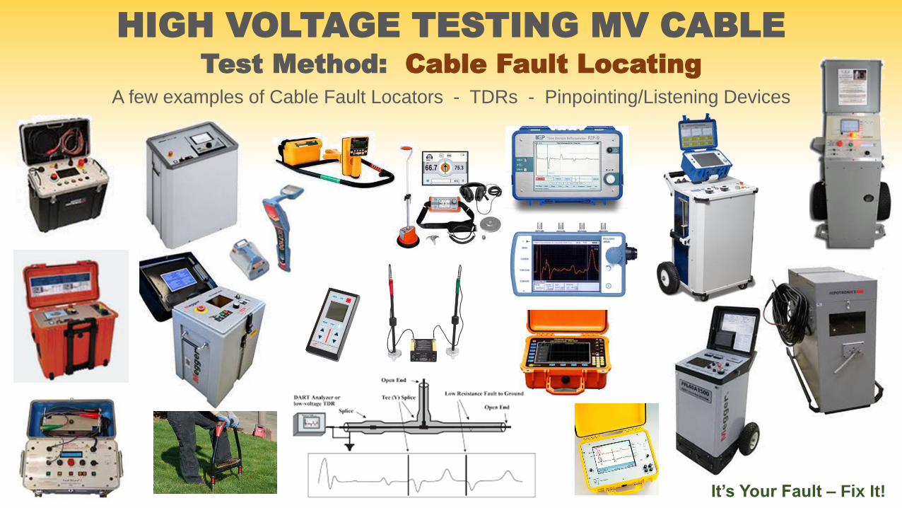
HIGH VOLTAGE TESTING MV CABLETest Method: Cable Fault Locating
A few examples of Cable Fault Locators - TDRs - Pinpointing/Listening Devices
It’s Your Fault – Fix It!
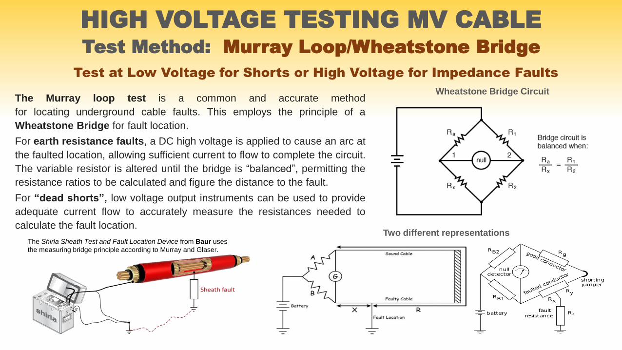
HIGH VOLTAGE TESTING MV CABLETest Method: Murray Loop/Wheatstone Bridge
The Murray loop test is a common and accurate method
for locating underground cable faults. This employs the principle of a
Wheatstone Bridge for fault location.
For earth resistance faults, a DC high voltage is applied to cause an arc at
the faulted location, allowing sufficient current to flow to complete the circuit.
The variable resistor is altered until the bridge is “balanced”, permitting the
resistance ratios to be calculated and figure the distance to the fault.
For “dead shorts”, low voltage output instruments can be used to provide
adequate current flow to accurately measure the resistances needed to
calculate the fault location.
Wheatstone Bridge Circuit
Two different representationsThe Shirla Sheath Test and Fault Location Device from Baur uses
the measuring bridge principle according to Murray and Glaser.
Test at Low Voltage for Shorts or High Voltage for Impedance Faults

http://www.neetrac.gatech.edu
Perhaps the best source for information coveringall types of cable testing, especially VLF andrelated diagnostic testing of cables, is NEETRAC atGeorgia Tech. http://www.neet rac.gatech.edu
HIGH VOLTAGE TESTING MV CABLECommon Methods for Factory & Field Testing
Most of the information presented here was original material prepared by HVI.
Some of the technical descriptions were a composite of HVI material and that of
others presented in the public domain. Many photos were of HVI products and
from other vendors of high voltage test equipment. If you require additional
information, please contact HVI. We are ready to help in any way we can.
www.hvinc.com
ISO 9001 2015 MADE IN THE USA
Advanced test equipment for high voltage proof and preventive maintenance testing of electrical apparatus www.hvinc.com
HVI - The World’s Source for
High Voltage Test Equipment
THANK YOU FOR YOUR INTEREST IN HIGH VOLTAGE, INC.
For any comments or questions on the materials presented, contact HVI
at the below numbers or visit our website. We are always happy and
eager to help with any high voltage testing needs. Always call HVI first.
www.hvinc.comCopyright laws apply