Embed Size (px)
Citation preview
HYDRO-GEAR 310-3000 INTEGRATED HYDROSTATIC TRANSAXLE SERV MANL
Table of Contents – Page 1 of 2
FOREWORD
DESCRIPTION AND OPERATION
INTRODUCTION GENERAL DESCRIPTION INTRODUCTION HYDRAULIC SCHEMATIC TECHNICAL SPECIFICATIONS PRODUCT IDENTIFICATION
SAFETY PERSONAL SAFETY TOOL SAFETY WORK AREA SAFETY SERVICING SAFETY
TROUBLESHOOTING
SERVICE AND MAINTENANCE EXTERNAL MAINTENANCE SERVICE AND MAINTENANCE PROCEDURES FLUIDS BRAKE MAINTENANCE RETURN TO NEUTRAL SETTING HAND CONTROL RETURN TO NEUTRAL SETTING FOOT CONTROL PURGING PROCEDURES
REPAIR GENERAL INSTRUCTIONS REQUIRED TOOLS TORQUE SPECIFICATIONS TRANSAXLE REMOVAL LIMITED DISASSEMBLY HOW TO USE THIS MANUAL BRAKE ASSEMBLY BYPASS ASSEMBLY CONTROL ARM ASSEMBLY TORQUE BRACKET ASSEMBLY FAN AND PULLEY ASSEMBLY INPUT SHAFT ASSEMBLY CHARGE PUMP ASSEMBLY LOWER HOUSING/FILTER/MANIFOLD ASSEMBLY PLANETARY DIFFERENTIAL ASSEMBLY MOTOR/CENTER SECTION/PUMP ASSEMBLY
HYDRO-GEAR 310-3000 INTEGRATED HYDROSTATIC TRANSAXLE SERV MANL
Table of Contents – Page 2 of 2
REPAIR - Continued DIRECTIONAL CONTROL ASSEMBLY TRANSAXLE INSTALLATION ASSEMBLY AFTER A COMPLETE TEAR-DOWN
PARTS LIST
GLOSSARY OF TERMS
Table of Contents
Section PageForeword .............................................................................................................................. i
Description and Operation................................................................................................. 1
Introduction ........................................................................................................................ 1General Description ................................................................................................................................. 1Introduction ............................................................................................................................................. 1Hydraulic Schematic ................................................................................................................................ 2Technical Specifications........................................................................................................................... 3Product Identification ............................................................................................................................... 3
Safety .................................................................................................................................. 4Personal Safety ....................................................................................................................................... 4Tool Safety .............................................................................................................................................. 4Work Area Safety .................................................................................................................................... 4Servicing Safety ....................................................................................................................................... 4
Troubleshooting ................................................................................................................. 5
Service and Maintenance................................................................................................... 6External Maintenance .............................................................................................................................. 6Service and Maintenance Procedures....................................................................................................... 6Fluids ...................................................................................................................................................... 7Brake Maintenance.................................................................................................................................. 8Return to Neutral Setting Hand Control..................................................................................................... 9Return to Neutral Setting Foot Control .................................................................................................... 10Purging Procedures` ............................................................................................................................... 11
Repair ................................................................................................................................ 12General Instructions............................................................................................................................... 12Required Tools....................................................................................................................................... 12Torque Specifications ............................................................................................................................. 12Transaxle Removal ................................................................................................................................ 12Limited Disassembly ............................................................................................................................. 12How to Use This Manual ........................................................................................................................ 13Brake Assembly ................................................................................................................................ 14,15Bypass Assembly.................................................................................................................................. 16Control Arm Assembly ....................................................................................................................... 17,18Torque Bracket Assembly ...................................................................................................................... 19Fan and Pulley Assembly ...................................................................................................................... 20Input Shaft Assembly ............................................................................................................................. 21Charge Pump Assembly ........................................................................................................................ 22Lower Housing/Filter/Manifold Assembly................................................................................................. 23Planetary Differential Assembly .......................................................................................................... 24,25Motor/Center Section/Pump Assembly .......................................................................................... 26,27,28Directional Control Assembly ................................................................................................................. 29Transaxle Installation ............................................................................................................................. 30Assembly After a Complete Tear-down.................................................................................................... 30
Parts List ...................................................................................................................... 31,32
Glossary of Terms ....................................................................................................... 33,34
310-3000 IHT i
FOREWORD
Headquartered in Sullivan, Illinois, Hydro-Gear isa world leader in the design, manufacture, andservice of quality hydrostatic transaxles for thelawn and garden industry. The mission of our com-pany is to be recognized by our customers andthe industry as a world-class supplier and thequality leader in everything we do.
This Service and Repair Manual is designed toprovide information useful in servicing the 310-3000Hydro-Gear Integrated HydrostaticTransaxle (IHT). The Troubleshooting Guide or-der number is BLN-51095.
Also included is a glossary of terms that arefrequently used throughout the industry and inHydro-Gear service publications. Understand-ing terminology is very important!!
It is necessary, and good shop practice, that yourservice area be equipped with proper tools andthe mechanics to be supplied with the latest in-formation available. All repair procedures
illustrated in this guide are suggested, but pre-ferred methods of repair.
Repair procedures require that the transaxle unitbe removed from the vehicle.
Some cleaning solvents are flammable. To avoidpossible fire, do not use cleaning solvents in anarea where a source of ignition may be present.
This is not a certification test or study guide for acertification test. If a technician is interested incertification, they should contact an agent repre-senting the OPE Technicians Certification of Aus-tin, Texas or their distributor. Many distributors willbe hosting certification testing. These studyguides will cover most of the products and manu-facturers in our industry.
For more information about Hydro-Gear or ourproducts, please contact one of our Central Ser-vice Distributors, or call our Technical ServiceDepartment at (217) 728-2581.
310-3000 IHT 1
INTRODUCTIONThe purpose of this manual is to provide infor-mation useful in servicing the Hydro-Gear 310-3000 Integrated Hydrostatic Transaxle (IHT). Thismanual includes transaxle general description,hydraulic schematic, technical specifications,product identification, safety, troubleshooting,maintenance, and repair procedures.
The transaxle normally will not require servicingduring the life of the vehicle in which it is installed.Should other servicing be required, the transaxlewill need to be thoroughly cleaned before begin-ning most procedures.
Please refer to the instructions titled “How to UseThis Manual” in the Repair Section for an expla-nation of the layout of the disassembly, inspec-tion, and reassembly portions of this manual.
GENERAL DESCRIPTIONThe 310-3000 is a self contained unit designedfor the transfer and control of power. It providesan infinitely variable speed range between zeroand maximum in both forward and reversemodes of operation.
This transaxle uses a variable displacementpump with a maximum displacement of 10 ccper revolution, and motor with a fixed displace-ment of 21cc per revolution. The variable dis-placement pump features a cradle swashplatewith a direct-proportional displacement control.Reversing the direction of the swashplate re-
verses the flow of oil from the pump and thus re-verses the direction of the motor output rotation.The pump and motor are of the axial piston de-sign and utilize spherical nosed pistons whichare held against a thrust race by internal com-pression springs.
The 310-3000 has a self contained fluid supplyand an internal filter. The fluid is drawn throughthe internal reservoir and feeds the fixed dis-placement gerotor charge pump. Excess fluid inthe charge circuit is discharged over the chargerelief valve and dumps back to case. Chargecheck valves in the center section are used tocontrol the makeup flow of the fluid to the low pres-sure side of the loop.
The transaxle is filled and tested at the factoryand should not require fluid or filter changes un-less the fluid becomes contaminated.
A cam style, block lifting bypass is utilized in the310-3000 to permit moving the vehicle for shortdistance at a maximum of 2 m.p.h. without start-ing the engine.
WARNING
Actuating the bypass will result in theloss of hydrostatic braking capacity. Themachine must be stationary on a levelsurface and in neutral when actuatingthe bypass.
The 310-3000 utilizes an in-line floating discbrake controlled by a "cam" style actuating arm.
SECTION 1. DESCRIPTION AND OPERATION
2 310-3000 IHT
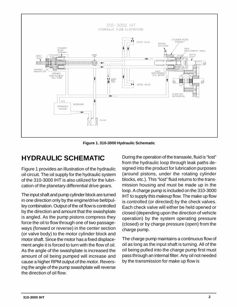
Figure 1. 310-3000 Hydraulic Schematic
HYDRAULIC SCHEMATICFigure 1 provides an illustration of the hydraulicoil circuit. The oil supply for the hydraulic systemof the 310-3000 IHT is also utilized for the lubri-cation of the planetary differential drive gears.
The input shaft and pump cylinder block are turnedin one direction only by the engine/drive belt/pul-ley combination. Output of the oil flow is controlledby the direction and amount that the swashplateis angled. As the pump pistons compress theyforce the oil to flow through one of two passage-ways (forward or reverse) in the center section(or valve body) to the motor cylinder block andmotor shaft. Since the motor has a fixed displace-ment angle it is forced to turn with the flow of oil.As the angle of the swashplate is increased theamount of oil being pumped will increase andcause a higher RPM output of the motor. Revers-ing the angle of the pump swashplate will reversethe direction of oil flow.
During the operation of the transaxle, fluid is “lost”from the hydraulic loop through leak paths de-signed into the product for lubrication purposes(around pistons, under the rotating cylinderblocks, etc.). This “lost” fluid returns to the trans-mission housing and must be made up in theloop. A charge pump is included on the 310-3000IHT to supply this makeup flow. The make up flowis controlled (or directed) by the check valves.Each check valve will either be held opened orclosed (depending upon the direction of vehicleoperation) by the system operating pressure(closed) or by charge pressure (open) from thecharge pump.
The charge pump maintains a continuous flow ofoil as long as the input shaft is turning. All of theoil being pulled into the charge pump first mustpass through an internal filter. Any oil not neededby the transmission for make up flow is

310-3000 IHT 3
discharged through the charge relief valve. Thecharge relief valve maintains the charge pres-sure at no more than 40 PSI.
The motor cylinder block mounts onto the splinedmotor shaft which drives the planetary differen-tial gear/differential assembly.
The bypass feature in the 310-3000 has a me-chanical lever which lifts the motor block off ofthe center section running surface, allowing anyoil flowing from the pump block to be dischargedinto the housing without turning the motor.
TECHNICALSPECIFICATIONSTechnical specifications for the 310-3000 IHT aregiven in Table 1.
PRODUCT IDENTIFICATIONThe model and configuration of the 310-3000 IHTcan be determined from the label shown in Fig-ure 2.
Overall Transaxle Reduction30.15:1
Input SpeedsMaximum: 3600 RPMMinimum: 1800 RPM
Maximum Tire Diameter23 inch; 584 mm
Axle Shaft OptionsType: KeyedDiameter: 1 inch; 25.4 mmType: FlangedDiameter: Hub
Brake TypeDisc
Weight of Unit58 lb; 26 kg
Table 1. 310-3000 Technical Specifications
Figure 2. 310-3000 Configuration Label
H Y D R O - G E A R SULLIVAN, IL. U.S.A.
I IIII III IIII II II 165758 310-3000
I II IIII IIII III III I II IIII 8 328 T1 476 Made in U.S.A.
Year Built
Date(Julian - day of year)
Type of Product and Build Information
Serial Number(unique number for that model - for that day)
OEM ModelNumber
Hydro-GearNumber
4 310-3000 IHT
SECTION 2. SAFETY
PERSONAL SAFETYCertain safety precautions must be observedwhile servicing or repairing the 310-3000 IHT.This section addresses some of these precau-tions but must not be considered an all-inclusivesource on safety information. This section is tobe used in conjunction with all other safety mate-rial which may apply, such as:
Other manuals pertaining to this machine
Local and shop safety rules and codes
Governmental safety laws and regulations
Be sure that you know and understand theequipment and the hazards associated with it.Do not place speed above safety.
Notify your supervisor whenever you feel there isany hazard involving the equipment or the per-formance of your job.
Never allow untrained or unauthorized person-nel to service or repair the equipment.
WARNING
POTENTIAL FOR SERIOUS INJURY
Inattention to proper safety, operation, ormaintenance procedures could result inpersonal injury, or damage to the equip-ment. Before servicing or repairing the310-3000 IHT, fully read and understandthe safety precautions described in thissection.
Wear appropriate clothing. Loose orhangingclothing or jewelry can be hazardous.Use the appropriate safety equipment, such aseye and hearing protection, and safety-toe andslip-proof shoes.
Never use compressed air to clean debris fromyourself or your clothing.
TOOL SAFETYUse the proper tools and equipment for the task.
Inspect each tool before use and replace any toolthat may be damaged or defective.
WORK AREA SAFETYKeep the work area neat and orderly. Be sure itis well lit, that extra tools are put away, trash andrefuse are in the proper containers, and dirt ordebris have been removed from the working ar-eas of the machine.
The floor should be clean and dry, and all exten-sion cords or similar trip hazards should be re-moved.
SERVICING SAFETYCertain procedures may require the vehicle tobe disabled in order to prevent possible injuryto the servicing technician and/or bystanders.
The loss of hydrostatic drive line power may re-sult in the loss of hydrostatic braking capability.Proper brake maintenance is very importantshould this condition develop.
Some cleaning solvents are flammable. Use onlyapproved cleaning materials: do not use explo-sive or flammable liquids to clean the equipment.
To avoid possible fire do not use cleaning sol-vents in an area where a source of ignition maybe present
Discard used cleaning material in the appropri-ate containers.
This symbol points out importantsafety instructions which, if not followed, couldendanger the personal safety and/or propertyof yourself and others. Read and follow all in-structions in this manual before attemptingmaintenance on your transaxle. When you seethis symbol - HEED ITS WARNING.
310-3000 IHT 5
WARNING
Do not attempt any servicing or adjust-ments with the engine running.Use extreme caution while inspecting thedrive belt assembly, and all vehicle link-age!
Follow all safety procedures outlined inthe vehicle owner’s manual!
SECTION 3. TROUBLESHOOTING
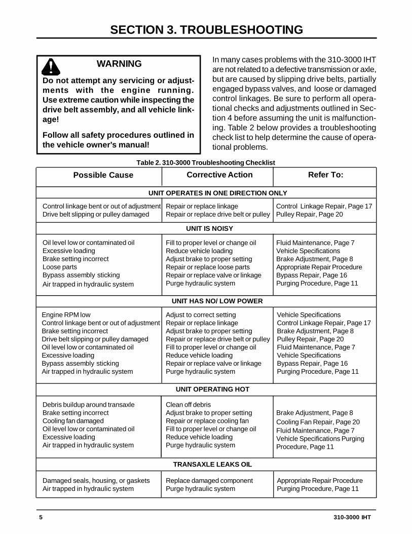
In many cases problems with the 310-3000 IHTare not related to a defective transmission or axle,but are caused by slipping drive belts, partiallyengaged bypass valves, and loose or damagedcontrol linkages. Be sure to perform all opera-tional checks and adjustments outlined in Sec-tion 4 before assuming the unit is malfunction-ing. Table 2 below provides a troubleshootingcheck list to help determine the cause of opera-tional problems.
Possible CauseTable 2. 310-3000 Troubleshooting Checklist
Corrective Action Refer To:
UNIT OPERATES IN ONE DIRECTION ONLY
Control linkage bent or out of adjustmentDrive belt slipping or pulley damaged
Repair or replace linkageRepair or replace drive belt or pulley
UNIT IS NOISY
Oil level low or contaminated oilExcessive loadingBrake setting incorrectLoose partsBypass assembly stickingAir trapped in hydraulic system
Fill to proper level or change oilReduce vehicle loadingAdjust brake to proper settingRepair or replace loose partsRepair or replace valve or linkagePurge hydraulic system
UNIT HAS NO/ LOW POWER
Engine RPM lowControl linkage bent or out of adjustmentBrake setting incorrectDrive belt slipping or pulley damagedOil level low or contaminated oilExcessive loadingBypass assembly stickingAir trapped in hydraulic system
Adjust to correct settingRepair or replace linkageAdjust brake to proper settingRepair or replace drive belt or pulleyFill to proper level or change oilReduce vehicle loadingRepair or replace valve or linkagePurge hydraulic system
UNIT OPERATING HOT
Debris buildup around transaxleBrake setting incorrectCooling fan damagedOil level low or contaminated oilExcessive loadingAir trapped in hydraulic system
Clean off debrisAdjust brake to proper settingRepair or replace cooling fanFill to proper level or change oilReduce vehicle loadingPurge hydraulic system
TRANSAXLE LEAKS OIL
Damaged seals, housing, or gasketsAir trapped in hydraulic system
Replace damaged componentPurge hydraulic system
Control Linkage Repair, Page 17Pulley Repair, Page 20
Fluid Maintenance, Page 7Vehicle SpecificationsBrake Adjustment, Page 8Appropriate Repair ProcedureBypass Repair, Page 16Purging Procedure, Page 11
Vehicle SpecificationsControl Linkage Repair, Page 17Brake Adjustment, Page 8Pulley Repair, Page 20Fluid Maintenance, Page 7Vehicle SpecificationsBypass Repair, Page 16Purging Procedure, Page 11
Brake Adjustment, Page 8Cooling Fan Repair, Page 20Fluid Maintenance, Page 7Vehicle Specifications PurgingProcedure, Page 11
Appropriate Repair ProcedurePurging Procedure, Page 11
6 310-3000 IHT
SECTION 4. SERVICE AND MAINTENANCE
NOTE: Any servicing dealer attemptinga warranty repair must have prior ap-proval before conducting maintenanceof a Hydro-Gear product unless the ser-vicing dealer is a current Authorized Hy-dro-Gear Service Center.
EXTERNAL MAINTENANCEReference Table 4., Page 13 for tools requiredin the maintenance of the 310-3000 IHT.
Regular external maintenance of the 310-3000IHT should include the following:
1. Check the vehicle operator’s manual for therecommended load ratings. Insure the cur-rent application does not exceed load rating.
2. Check oil level See Figure 3, Page 7.
3. Inspect the vehicle drive belt, idler pulley(s),and idler spring(s). Insure that no belt slip-page can occur. Slippage can cause low in-put RPM to the transaxle
4. Inspect the transaxle cooling fan for broken
or distorted blades and remove any obstruc-tions (grass clippings, leaves dirt, etc.).
5. Inspect the axle parking brake and vehiclelinkage to insure proper actuation of the park-ing brake.
6. Inspect the vehicle control linkage to the di-rectional control arm on transaxle. Also, in-sure the control arm is securely fastened tothe trunnion arm of the transaxle.
7. Inspect the bypass mechanism on thetransaxle and vehicle linkage to insure it ac-tuates and releases fully.
SERVICE ANDMAINTENANCEPROCEDURESAll the service and maintenance procedures pre-sented on the following pages can be performedwhile the 310-3000 is mounted on the vehicle.Any servicing beyond those given must be per-formed after the unit has been removed from thevehicle. Additional procedures are provided inSection 5. Repair Procedures.
310-3000 IHT 7
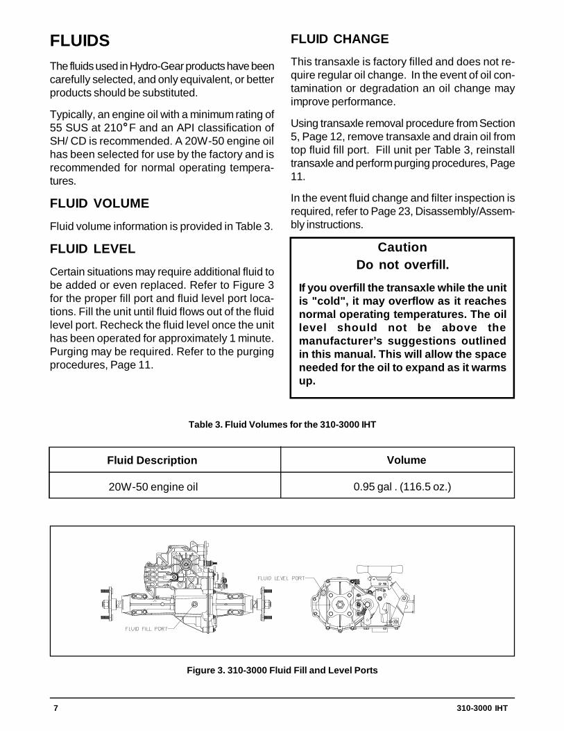
FLUIDSThe fluids used in Hydro-Gear products have beencarefully selected, and only equivalent, or betterproducts should be substituted.
Typically, an engine oil with a minimum rating of55 SUS at 210 F and an API classification ofSH/ CD is recommended. A 20W-50 engine oilhas been selected for use by the factory and isrecommended for normal operating tempera-tures.
FLUID VOLUME
Fluid volume information is provided in Table 3.
FLUID LEVEL
Certain situations may require additional fluid tobe added or even replaced. Refer to Figure 3for the proper fill port and fluid level port loca-tions. Fill the unit until fluid flows out of the fluidlevel port. Recheck the fluid level once the unithas been operated for approximately 1 minute.Purging may be required. Refer to the purgingprocedures, Page 11.
FLUID CHANGE
This transaxle is factory filled and does not re-quire regular oil change. In the event of oil con-tamination or degradation an oil change mayimprove performance.
Using transaxle removal procedure from Section5, Page 12, remove transaxle and drain oil fromtop fluid fill port. Fill unit per Table 3, reinstalltransaxle and perform purging procedures, Page11.
In the event fluid change and filter inspection isrequired, refer to Page 23, Disassembly/Assem-bly instructions.
CautionDo not overfill.
If you overfill the transaxle while the unitis "cold", it may overflow as it reachesnormal operating temperatures. The oillevel should not be above themanufacturer’s suggestions outlinedin this manual. This will allow the spaceneeded for the oil to expand as it warmsup.
Figure 3. 310-3000 Fluid Fill and Level Ports
Fluid Description
20W-50 engine oil
Volume
0.95 gal . (116.5 oz.)
Table 3. Fluid Volumes for the 310-3000 IHT
8 310-3000 IHT
BRAKE MAINTENANCEBRAKE SETTING
1. Remove the brake arm bias spring, and thenthe cotter pin securing the brake castle nut.
2. Insert a 0.015" feeler gage between the brakedisc and top brake puck, and then set thebrake by tightening or loosening the castlenut.
3. Adjust brake gap to 0.015" clearance.
4. Install the cotter pin to secure the castle nut,and then install the brake arm bias spring.
RETURN TO NEUTRAL SETTING(OPTIONAL FEATURE)
The return to neutral mechanism on the transmis-sion is designed to set the directional controlinto a neutral position. An optional feature, it isavailable in two versions. One version provideshand control, and the other, foot control. Settingprocedures are provided on pages 9 and 10.
WARNING
POTENTIAL FOR SERIOUS INJURY
Certain procedures require the vehicleengine to be operated and the vehicle tobe raised off of the ground. To preventpossible injury to the servicing techni-cian and/or bystanders, insure the ve-hicle is properly secured.
310-3000 IHT 9
RETURN TO NEUTRAL SETTINGHAND CONTROL
WARNINGPOTENTIAL FOR SERIOUS INJURY
Certain procedures require the vehicleengine to be operated and the vehicleto be raised off of the ground. To pre-vent possible injury to the servicingtechnician and/or bystanders, insurethe vehicle is properly secured.
The return to neutral mechanism on the trans-mission is designed to set the directional con-trol into a neutral position when the vehicle park-ing brake is engaged. Follow the proceduresbelow to properly adjust the return to neutralmechanism on the transaxle:
1. Confirm the transaxle is in the operatingmode (bypass disengaged). Raise thevehicle’s drive tires off the ground to allowfree rotation.
NOTE: It may be necessary to removethe drive tire from the axle hub to ac-cess the linkage control and thetransaxle control arm.
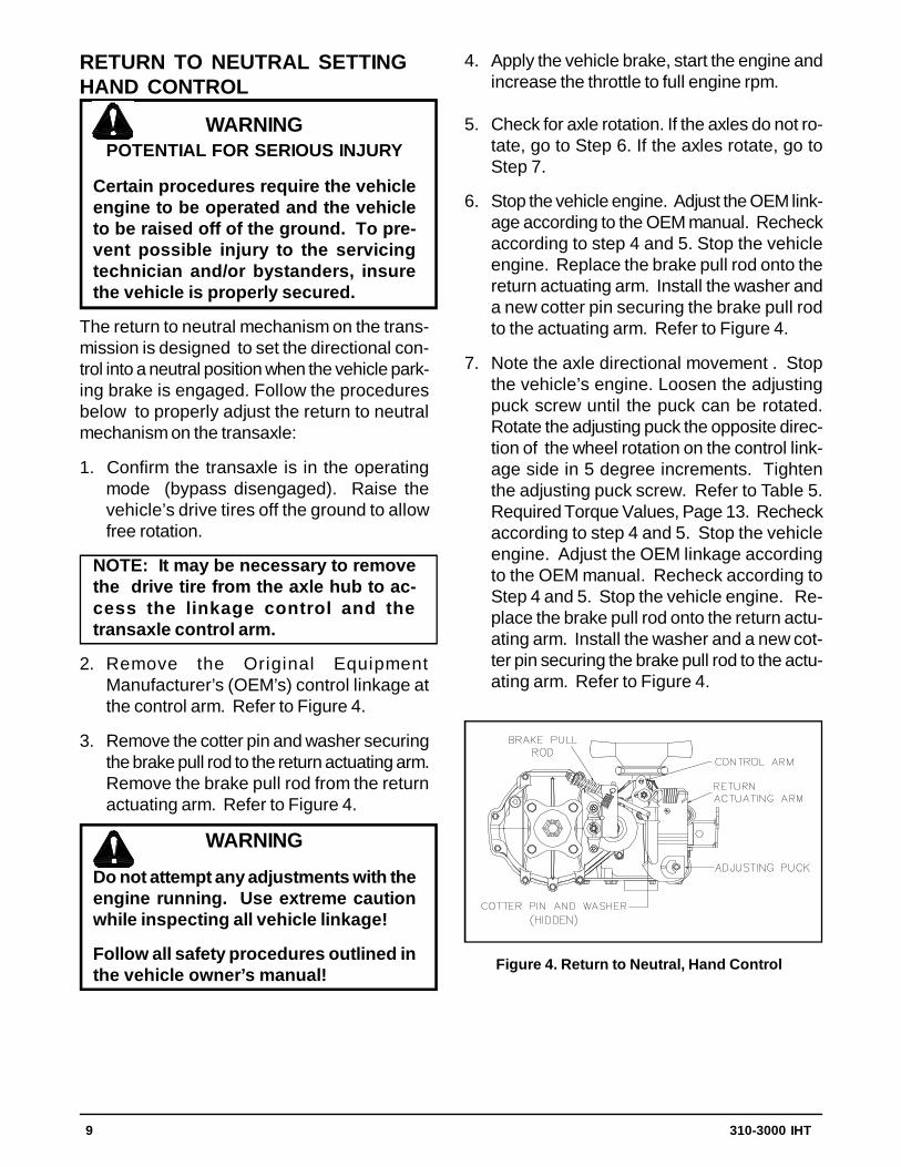
2. Remove the Original EquipmentManufacturer’s (OEM’s) control linkage atthe control arm. Refer to Figure 4.
3. Remove the cotter pin and washer securingthe brake pull rod to the return actuating arm.Remove the brake pull rod from the returnactuating arm. Refer to Figure 4.
WARNING
Do not attempt any adjustments with theengine running. Use extreme cautionwhile inspecting all vehicle linkage!
Follow all safety procedures outlined inthe vehicle owner’s manual!
Figure 4. Return to Neutral, Hand Control
4. Apply the vehicle brake, start the engine andincrease the throttle to full engine rpm.
5. Check for axle rotation. If the axles do not ro-tate, go to Step 6. If the axles rotate, go toStep 7.
6. Stop the vehicle engine. Adjust the OEM link-age according to the OEM manual. Recheckaccording to step 4 and 5. Stop the vehicleengine. Replace the brake pull rod onto thereturn actuating arm. Install the washer anda new cotter pin securing the brake pull rodto the actuating arm. Refer to Figure 4.
7. Note the axle directional movement . Stopthe vehicle’s engine. Loosen the adjustingpuck screw until the puck can be rotated.Rotate the adjusting puck the opposite direc-tion of the wheel rotation on the control link-age side in 5 degree increments. Tightenthe adjusting puck screw. Refer to Table 5.Required Torque Values, Page 13. Recheckaccording to step 4 and 5. Stop the vehicleengine. Adjust the OEM linkage accordingto the OEM manual. Recheck according toStep 4 and 5. Stop the vehicle engine. Re-place the brake pull rod onto the return actu-ating arm. Install the washer and a new cot-ter pin securing the brake pull rod to the actu-ating arm. Refer to Figure 4.
10 310-3000 IHT
RETURN TO NEUTRAL SETTINGFOOT CONTROL
WARNINGPOTENTIAL FOR SERIOUS INJURY
Certain procedures require the vehicleengine to be operated and the vehicle tobe raised off of the ground. To preventpossible injury to the servicing techni-cian and/or bystanders, insure the ve-hicle is properly secured.
The return to neutral mechanism on the transmis-sion is designed to set the directional controlinto a neutral position when the operator removestheir foot from the foot control. Follow the proce-dures below to properly adjust the return to neu-tral mechanism on the transaxle:
1. Confirm the transaxle is in the operating mode(bypass disengaged). Raise the vehicle’sdrive tires off the ground to allow free rota-tion.
NOTE: It may be necessary to removethe drive tire from the axle hub to accessthe linkage control and the transaxle con-trol arm.
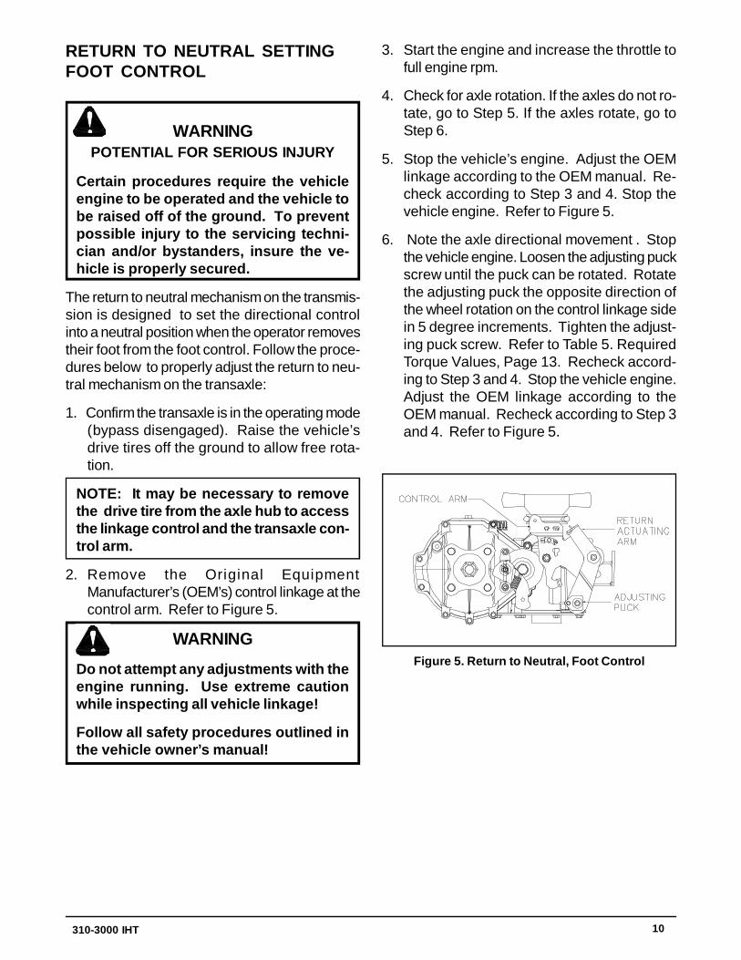
2. Remove the Original EquipmentManufacturer’s (OEM’s) control linkage at thecontrol arm. Refer to Figure 5.
WARNING
Do not attempt any adjustments with theengine running. Use extreme cautionwhile inspecting all vehicle linkage!
Follow all safety procedures outlined inthe vehicle owner’s manual!
3. Start the engine and increase the throttle tofull engine rpm.
4. Check for axle rotation. If the axles do not ro-tate, go to Step 5. If the axles rotate, go toStep 6.
5. Stop the vehicle’s engine. Adjust the OEMlinkage according to the OEM manual. Re-check according to Step 3 and 4. Stop thevehicle engine. Refer to Figure 5.
6. Note the axle directional movement . Stopthe vehicle engine. Loosen the adjusting puckscrew until the puck can be rotated. Rotatethe adjusting puck the opposite direction ofthe wheel rotation on the control linkage sidein 5 degree increments. Tighten the adjust-ing puck screw. Refer to Table 5. RequiredTorque Values, Page 13. Recheck accord-ing to Step 3 and 4. Stop the vehicle engine.Adjust the OEM linkage according to theOEM manual. Recheck according to Step 3and 4. Refer to Figure 5.
Figure 5. Return to Neutral, Foot Control
310-3000 IHT 11
PURGING PROCEDURESDue to the effects air has on efficiency in hydro-static drive applications, it is critical that it bepurged from the system.
These purge procedures should be implementedany time a hydrostatic system has been openedto facilitate maintenance or any additional oilhas been added to the system.
Air creates inefficiency because its compressionand expansion rate is higher than that of the oilnormally approved for use in hydrostatic drivesystems.
The resulting symptoms in hydrostatic systemsmay be:
1. Noisy operation
2. Lack of power or drive after short term op-eration
3. High operation temperature and excessiveexpansion of "oil", in the latter case, oil mayoverflow.
Before starting, make sure the transaxle/ trans-mission is at the proper oil level. If it is not, fill tothe manufacturers suggestions outlined in thevehicle owners manual.
The following procedures should be performedwith the vehicle drive wheels off the ground, thenrepeated under normal operating conditions.
1. With the bypass valve open and the enginerunning, slowly move the directional controlin both forward and reverse directions 5 to 6times, as air is purged from the unit, the oillevel will drop and bubbles may appear in theoil. After stopping the engine, add oil, as nec-essary. Fill to the level outlined in Figure 3,Page 7.
2. With the bypass valve closed and the enginerunning, slowly move the directional controlin both forward and reverse directions (5 to 6times). Check the oil level, and add oil as re-quired after stopping engine.
3. It may be necessary to repeat Steps 1 and 2until all the air is completely purged from thesystem. When the transaxle moves forwardand reverse, purging is complete.
CAUTION
DO NOT OVERFILL.
If you overfill the transaxle while the unitis "cold", it may overflow as it reachesnormal operating temperatures. The oillevel should not be above the levelshown in figure 3, Page 7. This will allowthe space needed for the oil to expandas it warms up.
12 310-3000 IHT
SECTION 5. REPAIR
NOTE: Any servicing dealer attemptinga warranty repair must have prior ap-proval before conducting maintenanceof a Hydro-Gear product unless the ser-vicing dealer is a current Authorized Hy-dro-Gear Service Center.
GENERAL INSTRUCTIONSCleanliness is a primary means of assuring sat-isfactory life on repaired units. Thoroughly cleanall exposed surfaces prior to any type of mainte-nance. Cleaning of all parts by using a solventwash and air drying is usually adequate. As withany precision equipment, all parts must be keptfree of foreign material and chemicals.
Protect all exposed sealing surfaces and opencavities from damage and foreign material. Theexternal surfaces should be cleaned before be-ginning any repairs.
Upon removal, it is recommended that all seals,O-rings, and gaskets be replaced. During instal-lation lightly lubricate all seals, O-rings, gasketswith a clean petroleum jelly prior to assembly.Also protect the inner diameter of seals by cov-ering the shaft with a cellophane (plastic wrap,etc.).
Parts requiring replacement must be replacedfrom the appropriate kits identified in the ItemsListing, found at the end of this manual.
REQUIRED TOOLSA list of tools required for the repair of the 310-3000 IHT is provided in Table 4, Page 13.
TORQUE SPECIFICATIONSTorque specifications for fasteners used onthe310-3000 IHT are provided in Table 5.
TRANSAXLE REMOVALIt is necessary to remove the 310-3000 from thevehicle before performing the repair procedurespresented in this section. Use the following pro-cedure to prepare the unit for removal from thevehicle.
1. With the vehicle wheels on the ground, loosenthe nut (119, Figure 19) Page 31, retainingthe hub (118, Figure 19) on the control sideof the transaxle only. Use an air impactwrench and a 1-1/8” socket to loosen the hub.
2. Lift the vehicle wheels from the ground andremove the nut completely.
3. Remove the wheel from the hub.
4. Using a wheel or gear puller, remove the hubfrom the shaft.
CAUTION
USE CARE IN REMOVING THE HUB TOPREVENT CRACKING.
LIMITED DISASSEMBLYThe following procedures are presented in theorder in which they must be performed to com-pletely disassemble the unit. Do not disassemblethe unit any farther than is necessary to accom-plish the required repairs. Each disassemblyprocedure is followed by a corresponding as-sembly procedure, and the disassembly processcan be halted after any given procedure.
Assembly is accomplished by performing theassembly portions of the procedures. If the unithas been completely disassembled, a summaryof the assembly procedures, in the order in whichthey should occur, is given on Page 30.
310-3000 IHT 13
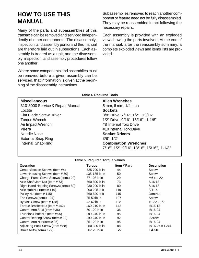
Miscellaneous310-3000 Service & Repair ManualLoctiteFlat Blade Screw DriverTorque WrenchAir Impact WrenchPliersNeedle NoseExternal Snap RingInternal Snap Ring
HOW TO USE THISMANUALMany of the parts and subassemblies of thistransaxle can be removed and serviced indepen-dently of other components. The disassembly,inspection, and assembly portions of this manualare therefore laid out in subsections. Each as-sembly is treated as a unit, and the disassem-bly, inspection, and assembly procedures followone another.
Where some components and assemblies mustbe removed before a given assembly can beserviced, that information is given at the begin-ning of the disassembly instructions.
Subassemblies removed to reach another com-ponent or feature need not be fully disassembled.They may be reassembled intact following thenecessary repairs.
Each assembly is provided with an explodedview showing the parts involved. At the end ofthe manual, after the reassembly summary, acomplete exploded views and items lists are pro-vided.
Allen Wrenches5 mm, 6 mm, 1/4 inchSockets3/8" Drive: 7/16", 1/2", 13/16"1/2” Drive: 9/16", 15/16", 1-1/8"#8 Internal Torx Drive#10 Internal Torx DriveSocket Drivers3/8", 1/2"Combination Wrenches7/16", 1/2", 9/16", 13/16", 15/16", 1-1/8"
Table 4. Required Tools
Operation Torque Item # Part DescriptionCenter Section Screws (Item #4) 525-700 lb-in 44 ScrewLower Housing Screws (Item # 50) 135-185 lb-in 50 ScrewCharge Pump Cover Screws (Item # 29) 87-108 lb-in 29 M6 x 1-22Axle Shaft Jam Nut (Item # 73) 660-800 lb-in 73 5/16-18Right Hand Housing Screws (Item # 80) 230-290 lb-in 80 5/16-18Axle Hub Nut (Item # 119) 200-295 lb-ft 119 3/4-16Pulley Nut (Item # 115) 360-520 lb-ft 115 Jam NutFan Screws (Item # 107) 35-50 lb-in 107 ScrewBypass Screw (Item # 138) 42-62 lb-in 138 10-32 x 1/2Torque Bracket Nut (Item # 142) 160-210 lb-in 142 5/16-18Control Arm Stud (Item # 36) 50-120 lb-in 36 5/16-24Trunnion Shaft Nut (Item # 95) 180-240 lb-in 95 5/16-24Control Bearing Screw (Item # 92) 190-240 lb-in 92 ScrewControl Arm Nut (Item # 95) 85-120 lb-in 95 5/16-24Adjusting Puck Screw (Item # 88) 250-320 lb-in 88 5/16-24 x 1-3/4Brake Nuts (Item # 127) 80-120 lb-in 127 1/4-20
Table 5. Required Torque Values
14 310-3000 IHT
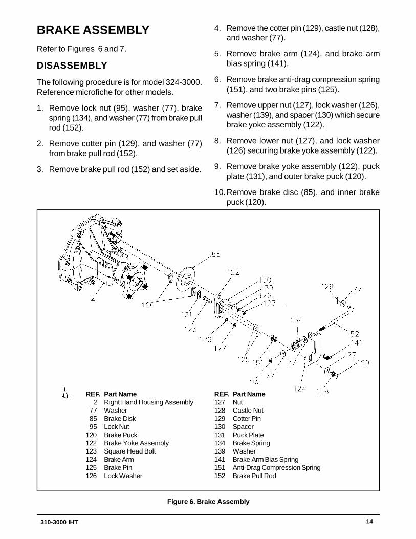
BRAKE ASSEMBLYRefer to Figures 6 and 7.
DISASSEMBLY
The following procedure is for model 324-3000.Reference microfiche for other models.
1. Remove lock nut (95), washer (77), brakespring (134), and washer (77) from brake pullrod (152).
2. Remove cotter pin (129), and washer (77)from brake pull rod (152).
3. Remove brake pull rod (152) and set aside.
4. Remove the cotter pin (129), castle nut (128),and washer (77).
5. Remove brake arm (124), and brake armbias spring (141).
6. Remove brake anti-drag compression spring(151), and two brake pins (125).
7. Remove upper nut (127), lock washer (126),washer (139), and spacer (130) which securebrake yoke assembly (122).
8. Remove lower nut (127), and lock washer(126) securing brake yoke assembly (122).
9. Remove brake yoke assembly (122), puckplate (131), and outer brake puck (120).
10.Remove brake disc (85), and inner brakepuck (120).
Figure 6. Brake Assembly
REF. Part Name127 Nut128 Castle Nut129 Cotter Pin130 Spacer131 Puck Plate134 Brake Spring139 Washer141 Brake Arm Bias Spring151 Anti-Drag Compression Spring152 Brake Pull Rod
REF. Part Name 2 Right Hand Housing Assembly 77 Washer 85 Brake Disk 95 Lock Nut120 Brake Puck122 Brake Yoke Assembly123 Square Head Bolt124 Brake Arm125 Brake Pin126 Lock Washer
310-3000 IHT 15
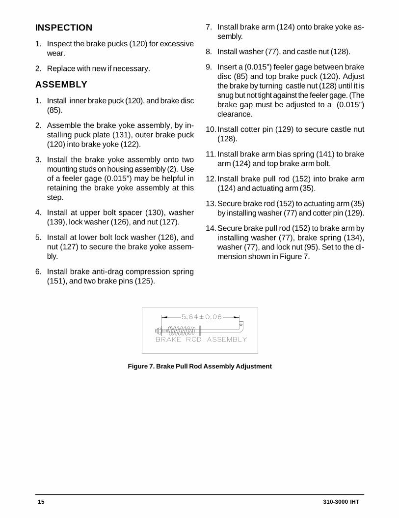
Figure 7. Brake Pull Rod Assembly Adjustment
INSPECTION
1. Inspect the brake pucks (120) for excessivewear.
2. Replace with new if necessary.
ASSEMBLY
1. Install inner brake puck (120), and brake disc(85).
2. Assemble the brake yoke assembly, by in-stalling puck plate (131), outer brake puck(120) into brake yoke (122).
3. Install the brake yoke assembly onto twomounting studs on housing assembly (2). Useof a feeler gage (0.015”) may be helpful inretaining the brake yoke assembly at thisstep.
4. Install at upper bolt spacer (130), washer(139), lock washer (126), and nut (127).
5. Install at lower bolt lock washer (126), andnut (127) to secure the brake yoke assem-bly.
6. Install brake anti-drag compression spring(151), and two brake pins (125).
7. Install brake arm (124) onto brake yoke as-sembly.
8. Install washer (77), and castle nut (128).
9. Insert a (0.015”) feeler gage between brakedisc (85) and top brake puck (120). Adjustthe brake by turning castle nut (128) until it issnug but not tight against the feeler gage. (Thebrake gap must be adjusted to a (0.015”)clearance.
10. Install cotter pin (129) to secure castle nut(128).
11. Install brake arm bias spring (141) to brakearm (124) and top brake arm bolt.
12. Install brake pull rod (152) into brake arm(124) and actuating arm (35).
13.Secure brake rod (152) to actuating arm (35)by installing washer (77) and cotter pin (129).
14.Secure brake pull rod (152) to brake arm byinstalling washer (77), brake spring (134),washer (77), and lock nut (95). Set to the di-mension shown in Figure 7.
16 310-3000 IHT
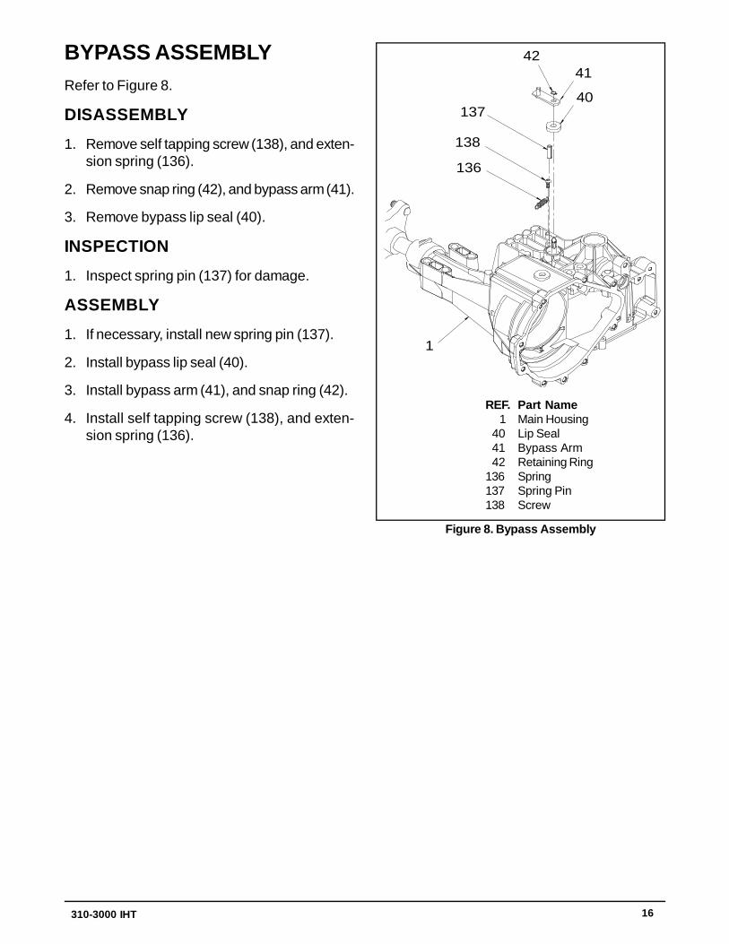
BYPASS ASSEMBLYRefer to Figure 8.
DISASSEMBLY
1. Remove self tapping screw (138), and exten-sion spring (136).
2. Remove snap ring (42), and bypass arm (41).
3. Remove bypass lip seal (40).
INSPECTION
1. Inspect spring pin (137) for damage.
ASSEMBLY
1. If necessary, install new spring pin (137).
2. Install bypass lip seal (40).
3. Install bypass arm (41), and snap ring (42).
4. Install self tapping screw (138), and exten-sion spring (136).
REF. Part Name 1 Main Housing 40 Lip Seal 41 Bypass Arm 42 Retaining Ring136 Spring137 Spring Pin138 Screw
Figure 8. Bypass Assembly
4241
40137
138
136
1
310-3000 IHT 17
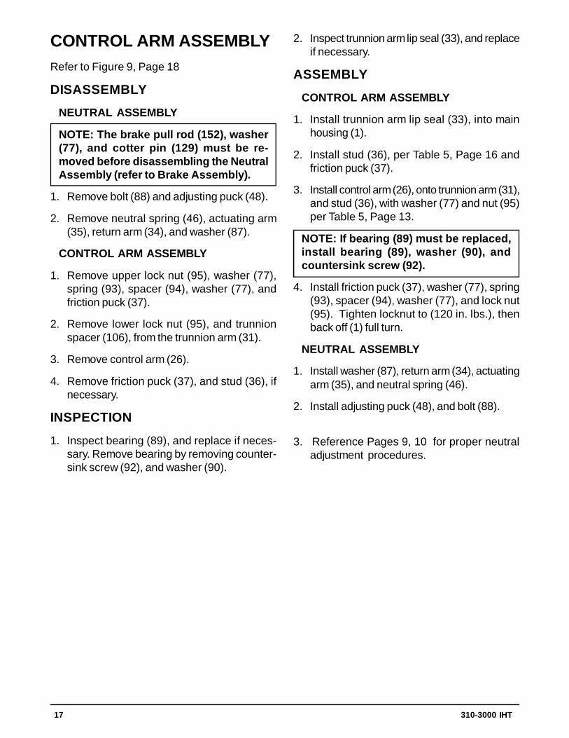
CONTROL ARM ASSEMBLYRefer to Figure 9, Page 18
DISASSEMBLY
NEUTRAL ASSEMBLY
NOTE: The brake pull rod (152), washer(77), and cotter pin (129) must be re-moved before disassembling the NeutralAssembly (refer to Brake Assembly).
1. Remove bolt (88) and adjusting puck (48).
2. Remove neutral spring (46), actuating arm(35), return arm (34), and washer (87).
CONTROL ARM ASSEMBLY
1. Remove upper lock nut (95), washer (77),spring (93), spacer (94), washer (77), andfriction puck (37).
2. Remove lower lock nut (95), and trunnionspacer (106), from the trunnion arm (31).
3. Remove control arm (26).
4. Remove friction puck (37), and stud (36), ifnecessary.
INSPECTION
1. Inspect bearing (89), and replace if neces-sary. Remove bearing by removing counter-sink screw (92), and washer (90).
2. Inspect trunnion arm lip seal (33), and replaceif necessary.
ASSEMBLY
CONTROL ARM ASSEMBLY
1. Install trunnion arm lip seal (33), into mainhousing (1).
2. Install stud (36), per Table 5, Page 16 andfriction puck (37).
3. Install control arm (26), onto trunnion arm (31),and stud (36), with washer (77) and nut (95)per Table 5, Page 13.
NOTE: If bearing (89) must be replaced,install bearing (89), washer (90), andcountersink screw (92).
4. Install friction puck (37), washer (77), spring(93), spacer (94), washer (77), and lock nut(95). Tighten locknut to (120 in. lbs.), thenback off (1) full turn.
NEUTRAL ASSEMBLY
1. Install washer (87), return arm (34), actuatingarm (35), and neutral spring (46).
2. Install adjusting puck (48), and bolt (88).
3. Reference Pages 9, 10 for proper neutraladjustment procedures.
18 310-3000 IHT
3132
8734
3546
4888
3637 26
8990
92
377793
94 7795
33106
95
REF. Part Name 26 Control Arm 31 Trunnion Arm 32 Trunnion Bushing 33 Trunnion Arm Lip Seal 34 Return Arm 35 Actuating Arm 36 Stud 37 Friction Puck 46 Spring 48 Adjusting Puck
Figure 9 Control Arm Assembly
REF. Part Name 77 Washer 87 Washer 88 Screw 89 Bearing 90 Locating Spacer 92 Countersink Screw 93 Spring 94 Spacer 95 Locknut 106 Trunnion Spacer

310-3000 IHT 19
TORQUE BRACKETASSEMBLYRefer to Figure 10.
DISASSEMBLY
1. Remove lock nut (142), and bolt (143), fromtorque bracket (102).
2. Remove torque bracket (102), from mainhousing (1).
ASSEMBLY
1. Install torque bracket (102), onto main hous-ing (1).
2. Install lock nut (142), and bolt (143), to se-cure torque bracket (102) to main housing(1). Reference Table 5, Page 13 for torquevalues.
REF. Part Name 1 Main Housing102 Torque Bracket142 Lock Nut143 Bolt
Figure 10. Torque Bracket Assembly
1
102
142
143143
102
142
20 310-3000 IHT
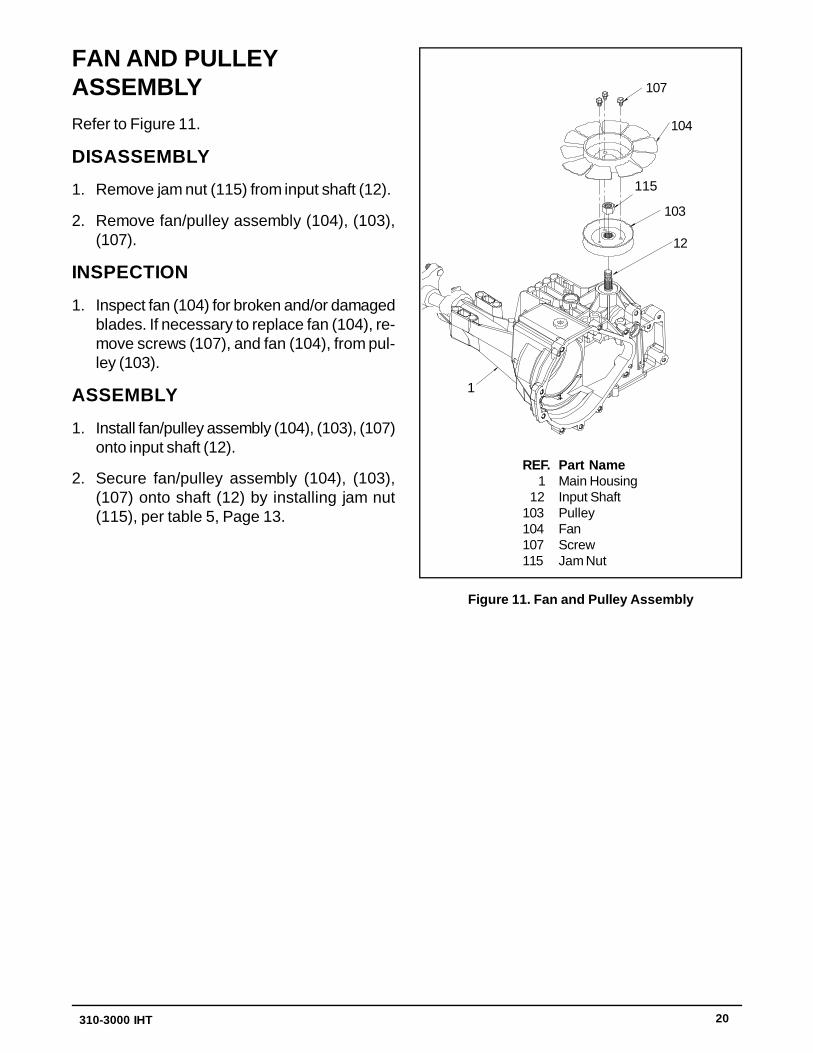
FAN AND PULLEYASSEMBLYRefer to Figure 11.
DISASSEMBLY
1. Remove jam nut (115) from input shaft (12).
2. Remove fan/pulley assembly (104), (103),(107).
INSPECTION
1. Inspect fan (104) for broken and/or damagedblades. If necessary to replace fan (104), re-move screws (107), and fan (104), from pul-ley (103).
ASSEMBLY
1. Install fan/pulley assembly (104), (103), (107)onto input shaft (12).
2. Secure fan/pulley assembly (104), (103),(107) onto shaft (12) by installing jam nut(115), per table 5, Page 13.
REF. Part Name 1 Main Housing 12 Input Shaft103 Pulley104 Fan107 Screw115 Jam Nut
107
115103
12
104
1
107
12
103
104
Figure 11. Fan and Pulley Assembly
310-3000 IHT 21
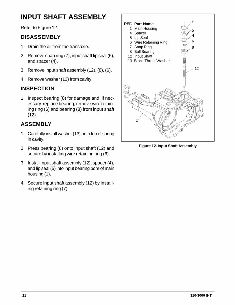
INPUT SHAFT ASSEMBLYRefer to Figure 12.
DISASSEMBLY
1. Drain the oil from the transaxle.
2. Remove snap ring (7), input shaft lip seal (5),and spacer (4).
3. Remove input shaft assembly (12), (8), (6).
4. Remove washer (13) from cavity.
INSPECTION
1. Inspect bearing (8) for damage and, if nec-essary replace bearing, remove wire retain-ing ring (6) and bearing (8) from input shaft(12).
ASSEMBLY
1. Carefully install washer (13) onto top of springin cavity.
2. Press bearing (8) onto input shaft (12) andsecure by installing wire retaining ring (6).
3. Install input shaft assembly (12), spacer (4),and lip seal (5) into input bearing bore of mainhousing (1).
4. Secure input shaft assembly (12) by install-ing retaining ring (7).
Figure 12. Input Shaft Assembly
7
5
468
12
1
7
546
8
12
REF. Part Name 1 Main Housing 4 Spacer 5 Lip Seal 6 Wire Retaining Ring 7 Snap Ring 8 Ball Bearing 12 Input Shaft 13 Block Thrust Washer
22 310-3000 IHT
1
52
53
54
29
REF. Part Name 1 Main Housing 29 Screw 52 Gerotor Assembly 53 O-ring 54 Gerotor Cover
52
53
54
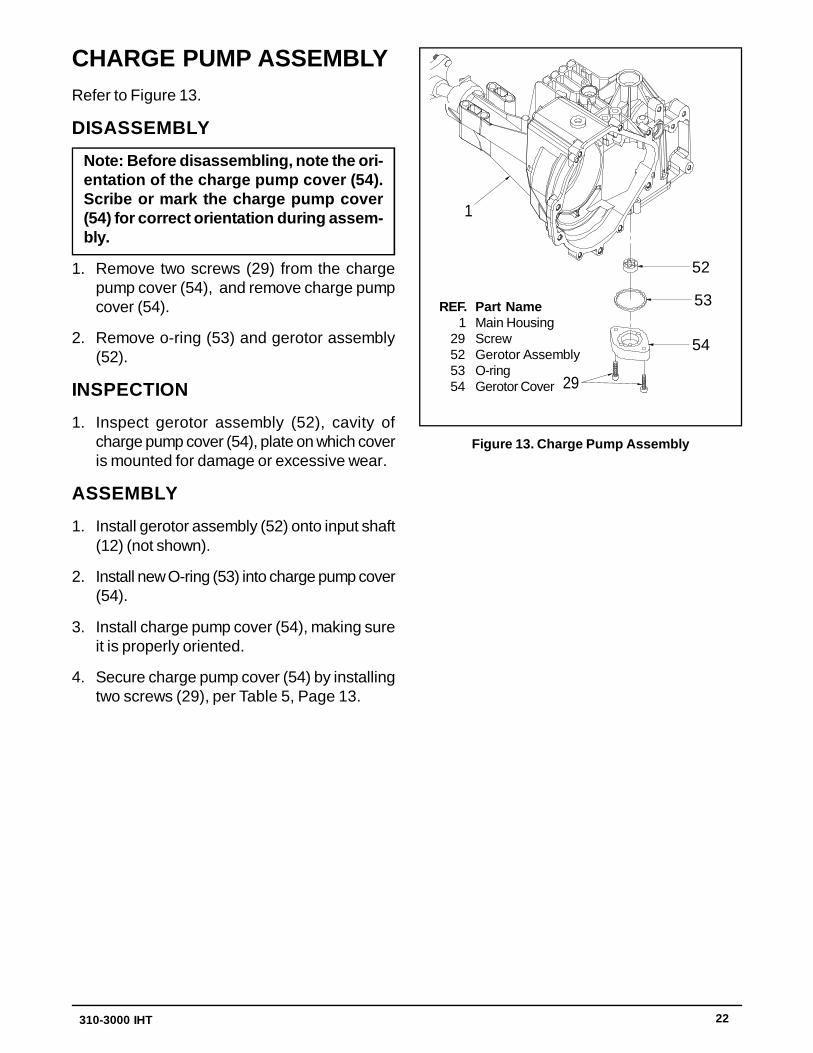
CHARGE PUMP ASSEMBLYRefer to Figure 13.
DISASSEMBLY
Note: Before disassembling, note the ori-entation of the charge pump cover (54).Scribe or mark the charge pump cover(54) for correct orientation during assem-bly.
1. Remove two screws (29) from the chargepump cover (54), and remove charge pumpcover (54).
2. Remove o-ring (53) and gerotor assembly(52).
INSPECTION
1. Inspect gerotor assembly (52), cavity ofcharge pump cover (54), plate on which coveris mounted for damage or excessive wear.
ASSEMBLY
1. Install gerotor assembly (52) onto input shaft(12) (not shown).
2. Install new O-ring (53) into charge pump cover(54).
3. Install charge pump cover (54), making sureit is properly oriented.
4. Secure charge pump cover (54) by installingtwo screws (29), per Table 5, Page 13.
Figure 13. Charge Pump Assembly
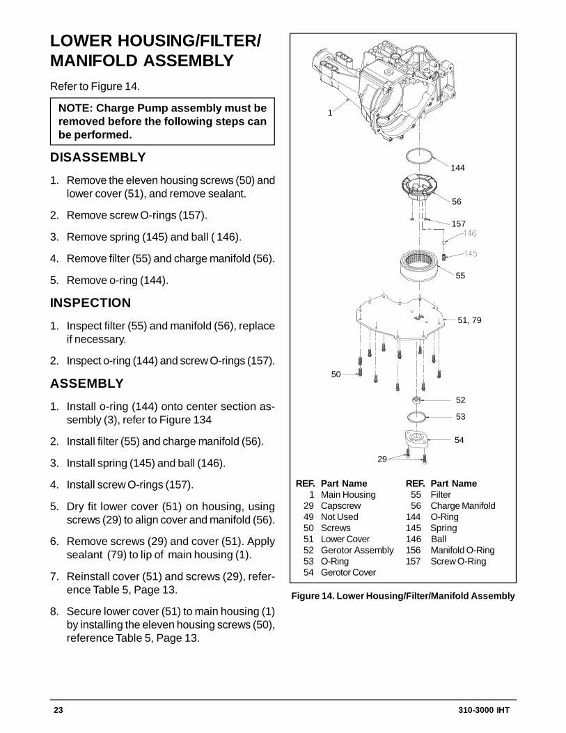
310-3000 IHT 23
REF. Part Name 1 Main Housing 29 Capscrew 49 Not Used 50 Screws 51 Lower Cover 52 Gerotor Assembly 53 O-Ring 54 Gerotor Cover
REF. Part Name 55 Filter 56 Charge Manifold144 O-Ring145 Spring146 Ball156 Manifold O-Ring157 Screw O-Ring
Figure 14. Lower Housing/Filter/Manifold Assembly
LOWER HOUSING/FILTER/MANIFOLD ASSEMBLYRefer to Figure 14.
NOTE: Charge Pump assembly must beremoved before the following steps canbe performed.
DISASSEMBLY
1. Remove the eleven housing screws (50) andlower cover (51), and remove sealant.
2. Remove screw O-rings (157).
3. Remove spring (145) and ball ( 146).
4. Remove filter (55) and charge manifold (56).
5. Remove o-ring (144).
INSPECTION
1. Inspect filter (55) and manifold (56), replaceif necessary.
2. Inspect o-ring (144) and screw O-rings (157).
ASSEMBLY
1. Install o-ring (144) onto center section as-sembly (3), refer to Figure 134
2. Install filter (55) and charge manifold (56).
3. Install spring (145) and ball (146).
4. Install screw O-rings (157).
5. Dry fit lower cover (51) on housing, usingscrews (29) to align cover and manifold (56).
6. Remove screws (29) and cover (51). Applysealant (79) to lip of main housing (1).
7. Reinstall cover (51) and screws (29), refer-ence Table 5, Page 13.
8. Secure lower cover (51) to main housing (1)by installing the eleven housing screws (50),reference Table 5, Page 13.
1
144
56
157
55
51, 79
50
52
53
54
29

24 310-3000 IHT
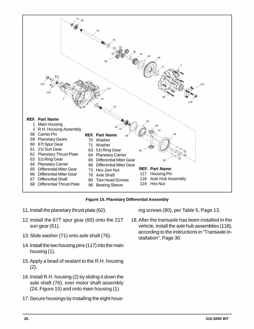
PLANETARY DIFFERENTIALASSEMBLYRefer to Figure 15, next page.
NOTE: Brake Assembly, and optionalReturn to Neutral have to be removed be-fore the following steps can be per-formed.
DISASSEMBLY
1. Remove the axle hub assembly (118) on con-trol side by removing nuts (119), and hub as-semblies (118).
2. Remove the eight torx head screws (80) thatsecure the R.H. housing assembly (2).
3. Remove R.H. housing assembly (2), whileholding axle shaft (76) in place.
4. Remove the two housing pins (117).
5. Remove washer (71) from axle shaft (76).
6. Remove spur gear (60), and thrust plate (62).
7. Remove 21T sun gear (61), and sleeve bear-ing (96).
8. Remove the planetary gears (59).
9. Remove washer (70), and axle shaft (76).
10.Remove the four carrier pins (58) from plan-etary carrier (64).
11. Remove 51T ring gear (63) from main hous-ing (1).
12.Remove the two miter gears (66), and differ-ential shaft (67).
13.Remove planetary carrier (64) and differen-tial thrust plate (68).
14. If necessary, remove the second axle shaftassembly (76) from main housing (1).
15.Remove the seal from the shaft, if necessary.
INSPECTION
1. Inspect all gears for excessive wear or dam-age and replace if necessary.
2. Remove all sealant from both housings andinspect seal lands for damage when clean-ing.
3. If miter gear (65) needs replaced, remove jamnut (73) from axle shaft (76).
ASSEMBLY
1. If necessary, install L.H. Axle shaft assembly(76) into main housing (1). If necessary, re-assemble axle shaft assembly (76) by install-ing washer (70), miter gear (65), and jam nut(73) onto axle shaft (76).
2. Install differential thrust plate (68) into mainhousing (1).
3. Install planetary carrier (64) into main hous-ing (1).
4. Reassemble the two miter gears (66) ontodifferential shaft (67), and install assembly intoplanetary carrier (64).
5. Install 51T ring gear (63) into main housing(1).
6. Install the four carrier pins (58) into planetarycarrier (64).
7. If necessary, reassemble axle shaft assem-bly (76) by installing washer (70), miter gear(65), and jam nut (73) onto axle shaft (76).
8. Install R.H. Axle shaft assembly (76) partwayinto assembled differential components.
NOTE: It will be necessary to support theRH axle shaft in the partially installedposition while steps 9 through 16 arecompleted.
9. Assemble sleeve bearing (96) and sun gear(61), sliding them onto R.H. axle shaft. Thesmaller diameter on the sun gear OD shouldbe “IN”.
10. Install the four 15T planetary gears (59) onpins (80) . Make sure the planetary gears areproperly aligned with the sun gear. Mate thebevel gear on the end of the RH axle shaftwith the bevel gears in the differential assem-bly. Continue to support the RH axle shaft.
310-3000 IHT 25
73 65
76
70
C D
AB 96
6162 60
712
118
119
80
59
119
118
1
117
70
76
6573
68
64
66
6763
66
58
CD
AB
REF. Part Name 1 Main Housing 2 R.H. Housing Assembly 58 Carrier Pin 59 Planetary Gears 60 67t Spur Gear 61 21t Sun Gear 62 Planetary Thrust Plate 63 51t Ring Gear 64 Planetary Carrier 65 Differential Miter Gear 66 Differential Miter Gear 67 Differential Shaft 68 Differential Thrust Plate
REF. Part Name 117 Housing Pin 118 Axle Hub Assembly 119 Hex Nut
REF. Part Name 70 Washer 71 Washer 63 51t Ring Gear 64 Planetary Carrier 65 Differential Miter Gear 66 Differential Miter Gear 73 Hex Jam Nut 76 Axle Shaft 80 Torx Head Screws 96 Bearing Sleeve
Figure 15. Planetary Differential Assembly
11. Install the planetary thrust plate (62).
12. Install the 67T spur gear (60) onto the 21Tsun gear (61).
13.Slide washer (71) onto axle shaft (76).
14. Install the two housing pins (117) into the mainhousing (1).
15.Apply a bead of sealant to the R.H. housing(2).
16. Install R.H. housing (2) by sliding it down theaxle shaft (76), over motor shaft assembly(24, Figure 15) and onto main housing (1).
17.Secure housings by installing the eight hous-
ing screws (80), per Table 5, Page 13.
18. After the transaxle has been installed in thevehicle, install the axle hub assemblies (118),according to the instructions in “Transaxle in-stallation”, Page 30.
26 310-3000 IHT
MOTOR/CENTER SECTION/PUMP ASSEMBLYRefer to Figures 16 and 17, (next pages).
NOTE: Brake Assembly, Input Assembly,Charge Pump Assembly, and LowerHousing/Filter/Manifold Assembly haveto be removed before the following stepscan be performed.
DISASSEMBLY
1. Remove washer (82), snap ring (83), washer(82), 16T pinion gear (28), spacer (27), andshaft (28).
2. Remove motor thrust bearing retainer (57).
3. Remove motor thrust bearing (25), and 21ccmotor cylinder block assembly (21).
4. Remove each piston (23), spring (18), andpiston seat (22) from the 21cc motor cylinderblock assembly.
5. Remove bypass plate (38) from center sec-tion assembly (3).
6. Remove the three screws (44) from centersection assembly (3).
7. Lift center section assembly (3) out of mainhousing (1).
8. Remove the two center section assembly pins(43).
9. Remove bypass actuator (39) from the cen-ter section (3).
10.Remove 10cc pump cylinder block assem-bly (15).
11. Remove each piston (17), spring (18), pis-ton seat (16) from the 10cc pump cylinderblock assembly (21).
12.Remove block spring (14), and block thrustwasher (13) from shaft (12, Figure 10)
INSPECTION
1. Inspect running surface of thrust bearing (25)
for excessive wear (grooving or smearing).
2. Inspect each piston (23), spring (18), and pis-ton seat (22) in the motor cylinder block as-sembly.
3. Inspect seal lands of the 21cc motor cylinderblock assembly (21) for excessive wear(grooving or smearing).
4. Inspect the two running surfaces of centersection assembly (3) for excessive wear(grooving or smearing). Abnormal wear pat-terns will usually be visible. Any wear detect-able when a fingernail is dragged across thesurface is cause for rejection.
5. Inspect each piston (17), spring (18), pistonseat (16)
6. Inspect seal lands of 10cc pump cylinderblock assembly (15) for excessive wear(grooving or smearing).
ASSEMBLY
1. Install pump cylinder block thrust washer (13)and spring (14) onto input shaft assembly(12).
2. Install piston washers (18), springs (17), andpistons (18) in cylinder block (15).
3. Install pump cylinder block assembly (15). Besure spring tension is even around the entireblock.
4. Install the two center section assembly pins(43).
5. Install center section assembly (3) into mainhousing (1). Make sure center section seatsfully on its mating surface.
6. Secure center assembly section (3) by in-stalling three screws (44) reference Table 5,Page 13. Apply a few drops of loctite onscrews when installing.
7. Install bypass plate (38) into center sectionassembly (3).
310-3000 IHT 27
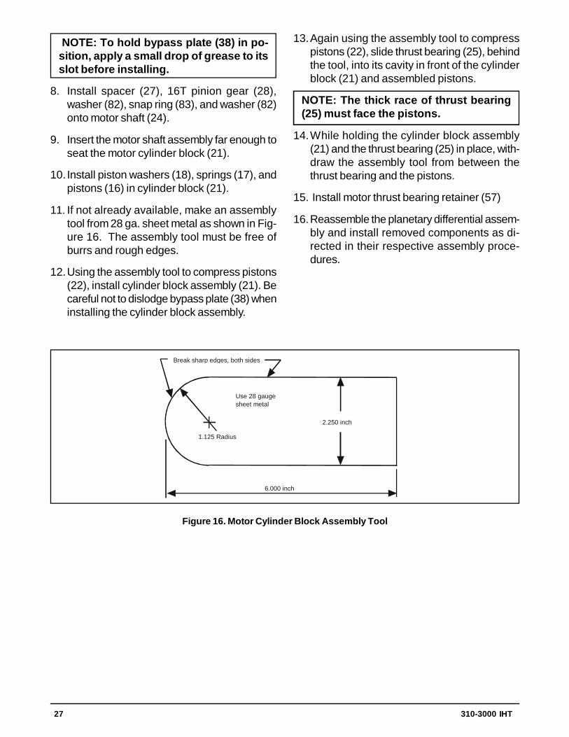
Figure 16. Motor Cylinder Block Assembly Tool
2.250 inch
1.125 Radius
6.000 inch
Break sharp edges, both sides
Use 28 gauge sheet metal
NOTE: To hold bypass plate (38) in po-sition, apply a small drop of grease to itsslot before installing.
8. Install spacer (27), 16T pinion gear (28),washer (82), snap ring (83), and washer (82)onto motor shaft (24).
9. Insert the motor shaft assembly far enough toseat the motor cylinder block (21).
10. Install piston washers (18), springs (17), andpistons (16) in cylinder block (21).
11. If not already available, make an assemblytool from 28 ga. sheet metal as shown in Fig-ure 16. The assembly tool must be free ofburrs and rough edges.
12.Using the assembly tool to compress pistons(22), install cylinder block assembly (21). Becareful not to dislodge bypass plate (38) wheninstalling the cylinder block assembly.
13.Again using the assembly tool to compresspistons (22), slide thrust bearing (25), behindthe tool, into its cavity in front of the cylinderblock (21) and assembled pistons.
NOTE: The thick race of thrust bearing(25) must face the pistons.
14.While holding the cylinder block assembly(21) and the thrust bearing (25) in place, with-draw the assembly tool from between thethrust bearing and the pistons.
15. Install motor thrust bearing retainer (57)
16.Reassemble the planetary differential assem-bly and install removed components as di-rected in their respective assembly proce-dures.
28 310-3000 IHT
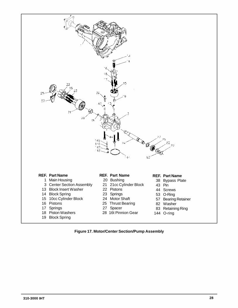
REF. Part Name 1 Main Housing 3 Center Section Assembly 13 Block Insert Washer 14 Block Spring 15 10cc Cylinder Block 16 Pistons 17 Springs 18 Piston Washers 19 Block Spring
REF. Part Name 38 Bypass Plate 43 Pin 44 Screws 53 O-Ring 57 Bearing Retainer 82 Washer 83 Retaining Ring 144 O-ring
REF. Part Name 20 Bushing 21 21cc Cylinder Block 22 Pistons 23 Springs 24 Motor Shaft 25 Thrust Bearing 27 Spacer 28 16t Pinnion Gear
Figure 17. Motor/Center Section/Pump Assembly
310-3000 IHT 29
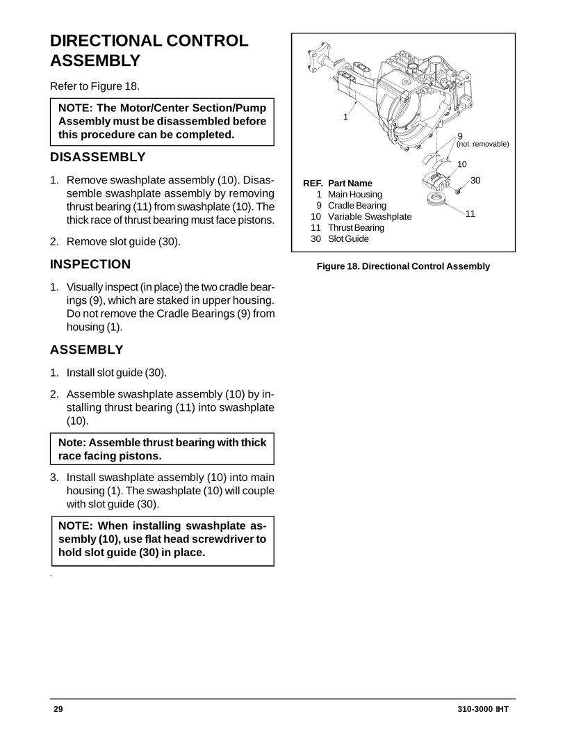
Figure 18. Directional Control Assembly
DIRECTIONAL CONTROLASSEMBLYRefer to Figure 18.
NOTE: The Motor/Center Section/PumpAssembly must be disassembled beforethis procedure can be completed.
DISASSEMBLY
1. Remove swashplate assembly (10). Disas-semble swashplate assembly by removingthrust bearing (11) from swashplate (10). Thethick race of thrust bearing must face pistons.
2. Remove slot guide (30).
INSPECTION
1. Visually inspect (in place) the two cradle bear-ings (9), which are staked in upper housing.Do not remove the Cradle Bearings (9) fromhousing (1).
ASSEMBLY
1. Install slot guide (30).
2. Assemble swashplate assembly (10) by in-stalling thrust bearing (11) into swashplate(10).
Note: Assemble thrust bearing with thickrace facing pistons.
3. Install swashplate assembly (10) into mainhousing (1). The swashplate (10) will couplewith slot guide (30).
NOTE: When installing swashplate as-sembly (10), use flat head screwdriver tohold slot guide (30) in place.
.
1
9
1030
11
REF. Part Name 1 Main Housing 9 Cradle Bearing 10 Variable Swashplate 11 Thrust Bearing 30 Slot Guide
11
9
30
(not removable)
30 310-3000 IHT
ASSEMBLY AFTER ACOMPLETE TEAR-DOWNIf the unit has been torn down completely, the fol-lowing summary identifies the assembly proce-dures necessary to completely assemble the unit,in the order they must be completed. Each as-sembly procedure is located by a page refer-ence.
The part reference numbers provided in eachassembly procedure are keyed to the individualexploded views, and are also keyed to the com-plete unit exploded view, Figure 19.
1. Assemble the Directional Control Assembly(Page 29).
2. Assemble the Motor/Center Section/PumpAssembly (Page 26,27,28).
3. Assemble the Planetary Differential Assem-bly (Page 24,25).
4. Assemble the Lower Housing/Filter/ManifoldAssembly (Page 23).
5. Assemble the Charge Pump Assembly(Page 22).
6. Assemble the Input Shaft Assembly (Page21).
7. Assemble the Fan and Pulley Assembly(Page 20).
8. Assemble the Torque Bracket Assembly(Page 19).
9. Assemble the Control Arm Assembly (Page17,18).
10.Assemble the Bypass Assembly (Page 16).
11. Assemble the Brake Assembly (Page 14,15).
TRANSAXLEINSTALLATIONUse the following procedure to complete instal-lation of the transaxle on the vehicle.
1. Install and secure the transaxle on the vehicleaccording to instructions in the vehicleowner’s manual.
2. Install the hub assembly (118, Figure 13) onthe shaft. Install hex nut (119, Figure 13).
3. With the vehicle raised, install the wheel onthe hub, and retain with the wheel lug nuts.
4. Lower the vehicle wheels to the ground, andtorque the nut retaining the hub to 290 to 295lb.-ft., using an air impact wrench.
5. Tighten the wheel lug nuts.

310-3000 IHT 31
Figure 19. 310-3000 IHT Exploded View

32 310-3000 IHT
NO. DESCRIPTION1 Main Housing Assembly2 R.H. Housing Assembly3 Center Section Assembly4 Spacer5 Lip Seal6 Wire Retaining Ring7 Retaining Ring8 Ball Bearing9 Cradle Bearing10 Variable Swashplate11 Thrust Bearing12 Input Shaft13 Block Thrust Washer14 Block Spring15 10cc Cylinder Block Assembly21 21cc Cylinder Block Assembly24 Output (Motor) Shaft25 Thrust Bearing26 Control Arm27 Spacer28 16T Pinion Gear29 Cap Screw M6 X 1-2230 Slot Guide31 Trunnion Arm32 Trunnion Bushing33 Lip Seal34 Return Arm35 Actuating Arm36 Stud 5/16 - 2437 Friction Puck38 Bypass Plate39 Bypass Actuator40 Lip Seal41 Bypass Arm42 Retaining Ring43 Pin44 Screw46 Neutral Spring48 Adjusting Puck50 Screw , Self-Tapping51 Lower Cover52 Gerotor Assembly53 O-Ring54 Gerotor Cover55 Filter56 Charge Manifold57 Retainer, Motor Bearing58 Pin, Carrier59 15T Planet Gear60 67T Spur Gear61 21T Sun Gear62 Planet Thrust Plate63 51T Ring Gear64 Planetary Carrier65 Miter Gear, Differential (SPLINED)66 Miter Gear, Differential67 Shaft , Differential68 Differential Thrust Plate69 Flange Bearing70 Washer71 Washer73 Hex Jam Nut, 5/8 - 1874 Ball Bearing 6205-175 Seal, 1” ID X 2.0472” X 0.375”76 Shaft, Axle77 Washer
ITEMS LISTPart numbers are not provided in this manual. See microfiche or parts manual for part numbers.
NO. DESCRIPTION79 Gasket Material/Sealant80 Torx Head Screw 5/16 - 1881 Needle Bearing82 Washer83 Retaining Ring84 Lip Seal85 Brake Disc87 Washer88 Screw 5/16 - 24 X 1-3/489 Bearing90 Spacer, Locating91 O-Ring92 Countersunk Screw93 Spring Spacer94 Spacer95 Nut, Hex Lock 5/16 - 2496 Sleeve Bearing97 20W50 Oil102 Torque Bracket103 Pulley104 Fan106 Spacer, Trunnion107 Screw109 Vent Bushing110 Fitting Kit111 Cap-Vent Assembly113 Hose/ Fitting Assembly115 Jam Nut116 Retaining Ring117 Std Hlds Pins118 Hub Assembly 7/16 - 14119 Nut, Hex 3/4 - 16120 Puck, Brake121 Rib Neck Bolt, 2”122 Brake Yoke123 Bolt, Square-Head124 Arm, Brake125 Pins, Brake126 Lock Washer, 1/4"127 Nut, 1/4 - 20128 Nut, Castle129 Cotter Pin130 Spacer131 Puck Plate132 Rib Neck Bolt, 3”133 Wheel Stud 7/16-14134 Brake Spring136 Extension Spring137 Spring Pin138 Screw , Stap 10-32 X .5139 Washer141 Spring, Brake Arm Bias142 Hex Lock Nut 5/16 - 18143 Bolt 5/16 -15 X 2.5144 O-Ring145 Spring, Relief146 Ball , 7/16151 Compression Spring Brake Anti-Drag152 Brake Pull Rod153 Plug, Straight Thread154 Wire Retaining Ring155 Fan/ Pulley Assembly157 Screw O-Ring180 Manifold Kit202 Manifold O-Ring Kit203 Seal Kit (310-3000)
310-3000 IHT 33
Axial Piston: Type of design for hydraulic motors and pumps in which the pistons are arrangedparallel with the spindle (input or output shaft).
Bantam Duty: A descriptive term relating to the product capacity (meaning: light duty).
Bypass Valve: A valve whose primary function is to open a path for the fluid to bypass the motor orpump. Also referred to occasionally as the freewheel valve or dump valve.
Case Drain Line (Return Line): A line returning fluid from the component housing to the reservoir.
Cavitation: A concentrated gaseous condition within the fluid causing the rapid implosion of a gas-eous bubble.
Center Section: A device which acts as the valve body and manifold of the transmission.
Charge Pump: A device which supplies replenishing fluid to the fluid power system (closed loop).
Charge Pressure: The pressure at which replenishing fluid is forced into a fluid power system.
Charge Relief Valve: A pressure control valve whose primary function is to limit pressure in thecharge circuit.
Check Valve: A valve whose primary function is to restrict flow in one direction.
Closed Loop: A sealed and uninterrupted circulating path for fluid flow from the pump to the motorand back.
Decay Rate: The ratio of pressure decay over time.
End Cap: See “Center Section”
Entrained Air: A mechanical mixture of air bubbles having a tendency to separate from the liquidphase.
Gerotor: A positive displacement pump frequently used as a charge pump.
Hydraulic Motor: A device which converts hydraulic fluid power into mechanical force and motionby transfer of flow under pressure.
Hydraulic Pump: A device which converts mechanical force and motion into hydraulic fluid powerby producing flow.
Hydrostatic Pump: See “Hydraulic Pump”
SECTION 6. GLOSSARY OF TERMS
34 310-3000 IHT
Hydrostatic Transaxle: A multicomponent assembly including a gear case and a hydrostatic trans-mission.
Hydrostatic Transmission: The combination of a hydraulic pump and motor in one housing to forma device for the control and transference of power.
Inlet Line: A supply line to the pump.
Integrated Hydrostatic Transaxle (IHT): The combination of a hydrostatic transmission and gearcase in one housing to form a complete transaxle.
Manifold: A conductor which provides multiple connection ports.
Neutral: Typically described as a condition in which fluid flow and system pressure is below thatwhich is required to turn the output shaft of the motor.
Pressure Decay: A falling pressure.
Priming: The filling of the charge circuit and closed loop of the fluid power system during start up,frequently achieved by pressurizing the fluid in the inlet line.
Purging: The act of replacing air with fluid in a fluid power system by forcing fluid into all of thecomponents and allowing the air a path of escape.
Rated Flow: The maximum flow that the power supply system is capable of maintaining at a spe-cific operating pressure.
Scoring: Scratches in the direction of motion of mechanical parts caused by abrasive contami-nants.
Swash Plate: A mechanical device used to control the displacement of the pump pistons in a fluidpower system.
System Charge Check Valve: A valve controlling the replenishing flow of fluid from a charge circuitto the closed loop in a fluid power system.
System Pressure: The pressure which overcomes the total resistance in a system, including alllosses.
Valve: A device which controls fluid flow direction, pressure, or flow rate.
Variable Displacement Pump: A pump in which the displacement per cycle can be varied.
Volumetric Displacement: The volume for one revolution.