Embed Size (px)
Citation preview

Hydro Networks in GIS
• Network model
• Flow on Networks
• Hydrologic networks
• Linear referencing on networks
Some slides in this presentation were prepared by Dr Francisco Olivera

Raster to Vector Transition
• During the last week, you have been dealing with the flow of water through the landscape based on the raster data structures
• Today we are making a transition in which we are going to use vector network data to describe water pathways.
• We will connect the land and water flow systems by attaching the catchments and watersheds derived from raster data processing to our vector networks

Some terminology• Hydrography – the mapping of water features
• Blue line features on topographic maps (streams, rivers, lakes,…)
• More generally, hydrography also includes the mapping of bathymetry and extent of estuaries and coastal waters
• National Hydrography Dataset (NHD) – a data model for storing topographic map hydrography– Medium resolution (1:100K) is complete for US
– High resolution (1:24K) is complete for most of the US
• NHDPlus – a new data model integrating 1:100K resolution NHD with catchments and derived attributes from the National Elevation Dataset

National Hydrography Dataset
Five feature classes withNHDFLowline built intoA geometric network
NHDPoint, NHDLine,NHDArea are point, lineand area water features on map apart from flowlinesand waterbodies
Key feature classes

National Hydrography Dataset
NHD Waterbody

NHD Geometric Network
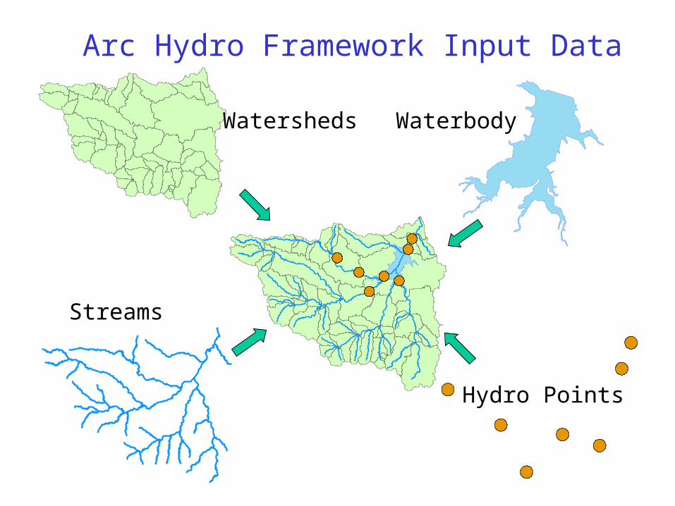
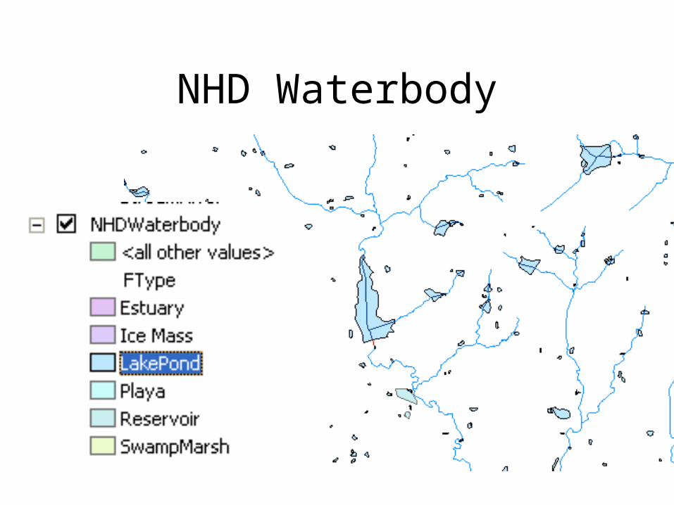
Streams
Watersheds Waterbody
Hydro Points
Arc Hydro Framework Input Data

!(
!(
!(!(
!( !(!( !(!( !(!(
!(!(
!(!(
!(!( !(!( !(
!( !(
!( !(!(!( !(!(
!(
!(
!(
!( !(!(!( !(
!(!(
!(!( !(!(!( !( !(!(!( !(!(
!( !(!(!( !(!(
!(!(
!(!(!(
!(
!(!(
!(
!(
!(!(
!(
!(
!(
!(!(!(
!(
Feature
Waterbody
HydroIDHydroCodeFTypeNameAreaSqKmJunctionID
HydroPoint
HydroIDHydroCodeFTypeNameJunctionID
Watershed
HydroIDHydroCodeDrainIDAreaSqKmJunctionIDNextDownID
ComplexEdgeFeature
EdgeType
Flowline
Shoreline
HydroEdge
HydroIDHydroCodeReachCodeNameLengthKmLengthDownFlowDirFTypeEdgeTypeEnabled
SimpleJunctionFeature
1HydroJunction
HydroIDHydroCodeNextDownIDLengthDownDrainAreaFTypeEnabledAncillaryRole
*
1
*
HydroNetwork
*
HydroJunction
HydroIDHydroCodeNextDownIDLengthDownDrainAreaFTypeEnabledAncillaryRole
HydroJunction
HydroIDHydroCodeNextDownIDLengthDownDrainAreaFTypeEnabledAncillaryRole
Arc Hydro FrameworkData Model

Hydro Network(NHD)
Basins Waterbody(NHD)
Arc Hydro Framework For South Florida
Hydro Points

Network Definition
• A network is a set of edges and junctions that
are topologically connected to each other.
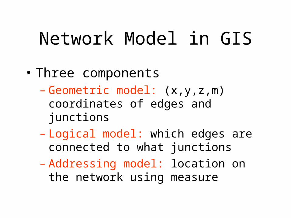
Network Model in GIS
• Three components– Geometric model: (x,y,z,m) coordinates of
edges and junctions– Logical model: which edges are connected to
what junctions– Addressing model: location on the network
using measure

Edges and Junctions
• Simple feature classes: points and lines• Network feature classes: junctions and edges• Edges can be
– Simple: one attribute record for a single edge
– Complex: one attribute record for several edges in a linear sequence
• A single edge cannot be branched
No!!

Polylines and Edges

Junctions
• Junctions exist at all points where edges join– If necessary they are added during network
building (generic junctions)
• Junctions can be placed on the interior of an edge e.g. stream gage
• Any number of point feature classes can be built into junctions on a single network

Connectivity Table
J124
J125
J123J126
E1 E3
E2J123 J124, E1
J124 J123, E1 J125, E2 J126, E3
J125 J124, E2
J126 J124, E3
Junction Adjacent Junction and Edge
This is the “Logical Network”
p. 132 of Modeling our World

Build Network Tables•Establishes connectivity of Edge and Junction features
•Enables tracing
•Generates Generic Junctions
Geometric Network Wizard in ArcCatalog

Snapping Features

Network Sources and Sinks
Each junctionfeature classin a network can have junctionswhich are sourcesor sinks for flow

Ancillary Role of Sink

Flow to a sink

Flags

Trace Solvers
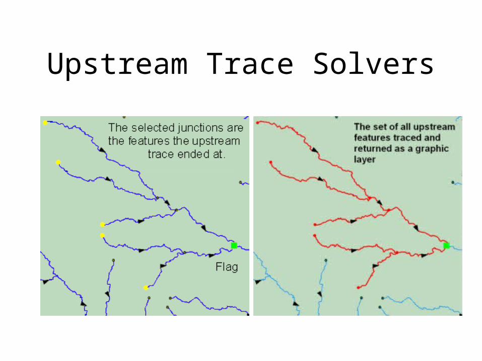
Upstream Trace Solvers

Hydrologic Networks• Hydrologic data includes:
– Single-line streams
– Double-line streams
– Braided streams
– Manmade channel systems
– Waterbodies
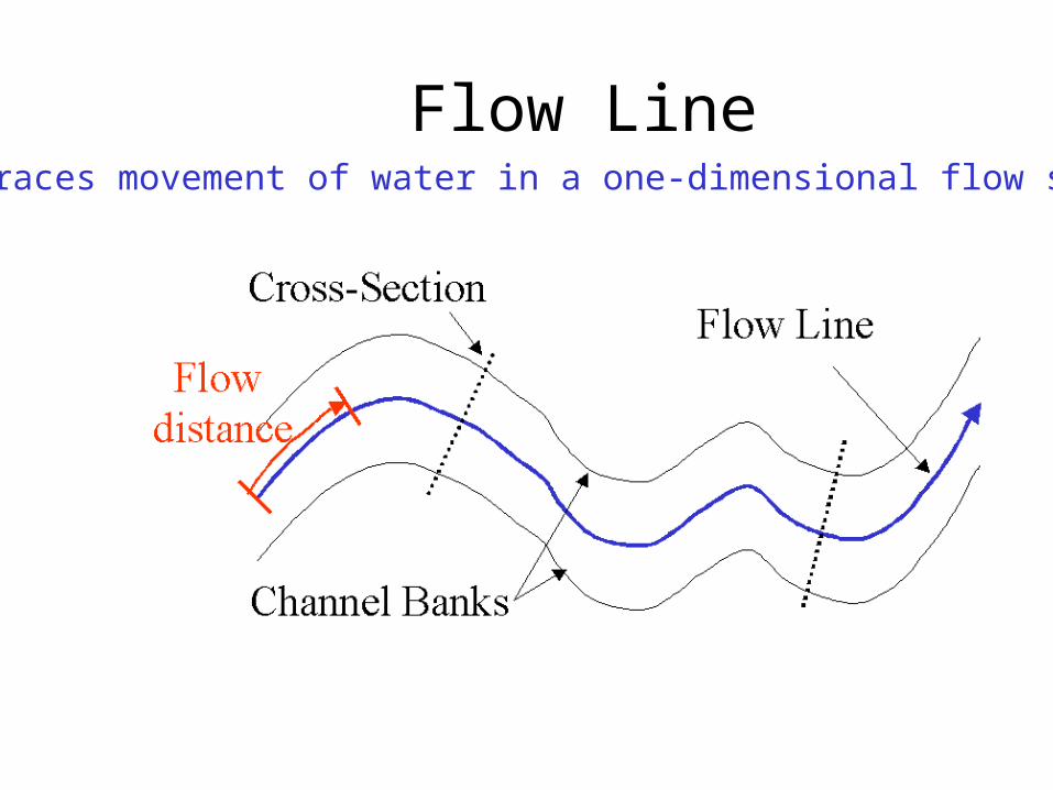
Flow LineTraces movement of water in a one-dimensional flow system

Location of the Flowline

Introduction to the Hydro Network
• Hydro Edge – think of Arc
• Hydro Junction – think of Node
• Waterbody – think of Polygon
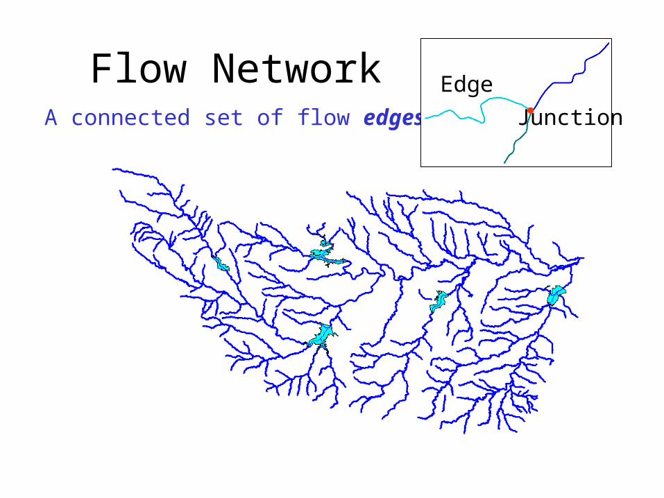
Flow NetworkA connected set of flow edges
Edge
Junction

Flowlines and Shorelines

Network Building
• Define flow-paths within
double-line streams and
waterbodies.
• Define network sinks and
sources.

Network Connectivity
Find connected Find loops

Network Flow Direction
• Enable flow in flow-paths.
• Disable flow in shorelines
Sink
Flow direction is unknown

Network Flow Direction
• Enable flow in flow-paths.
• Disable flow in shorelines
Sink
Flow direction is known

Uninitialized Flow Direction

Assigned Flow Direction
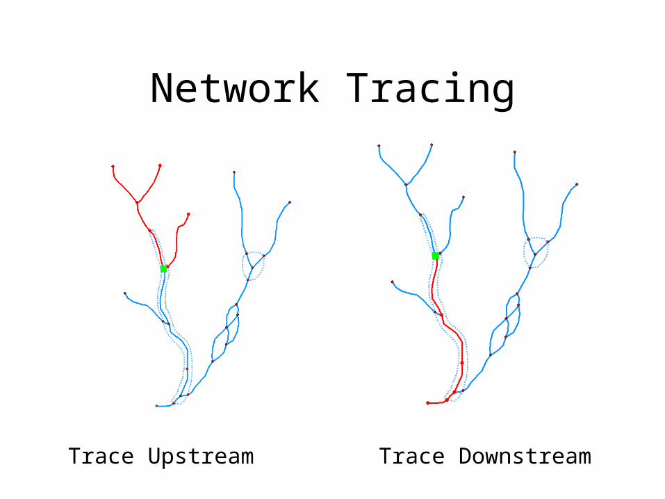
Network Tracing
Trace Upstream Trace Downstream

Trace Path
Find the shortest pathbetween two points on the network
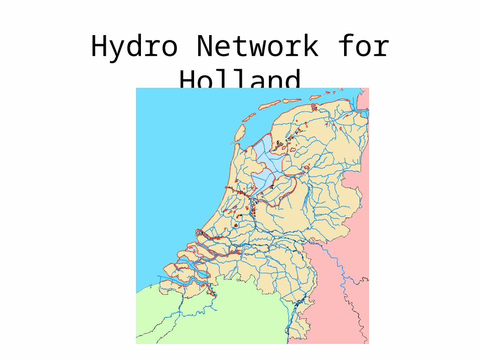
Hydro Network for Holland

Hydro Network for Colorado River Basin around Lake Travis
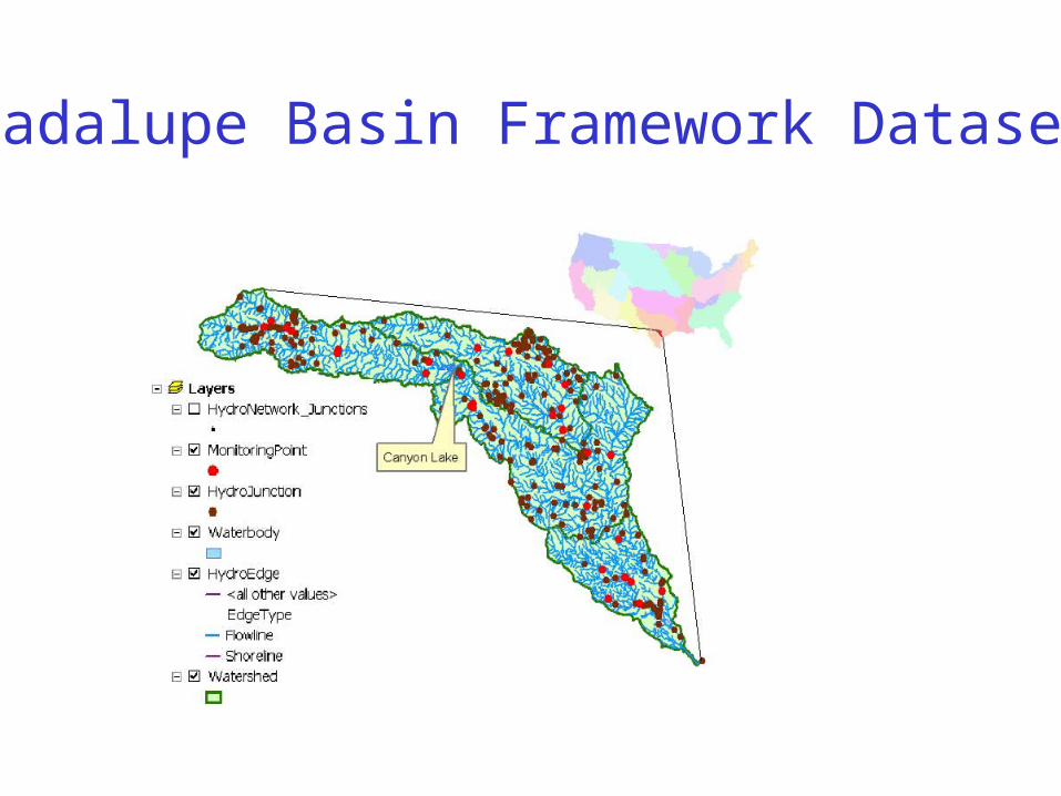
Guadalupe Basin Framework Dataset

Network Tracing on the Guadalupe Basin

Schematic Network

Hydro Network Junctions

Connecting Waterbodies using Relationships

Hydro Network through Canyon Lake

Linking Canyon Lake to the Network

Connecting Drainage Areas using Relationships

Connecting Drainage Areas to the Network
Area goes topoint on line
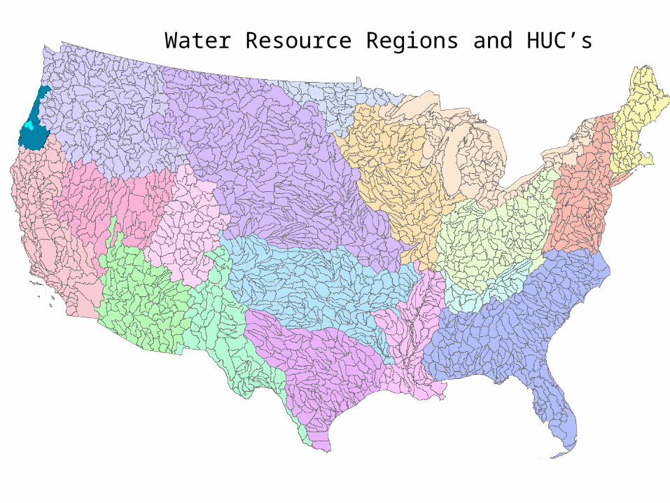
Water Resource Regions and HUC’s

NHDPlus for Region 17E

NHDPlus Reach Catchments ~ 3km2
About 1000 reach catchments in each 8-digit HUC
Average reach length = 2km 2.3 million reaches for continental US
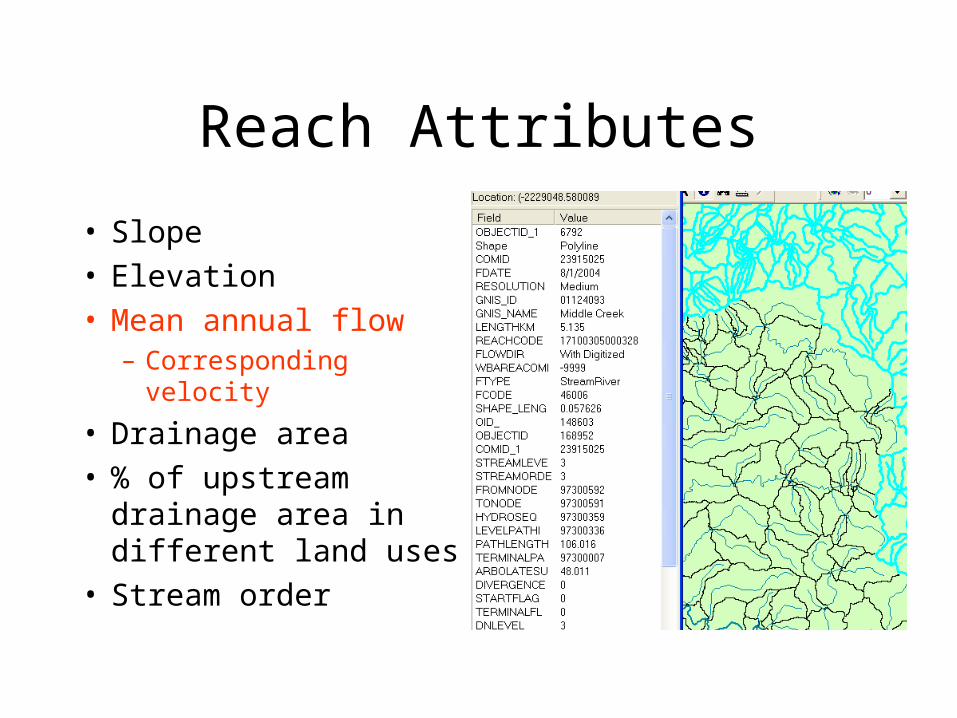
Reach Attributes
• Slope• Elevation• Mean annual flow
– Corresponding velocity
• Drainage area• % of upstream drainage
area in different land uses
• Stream order
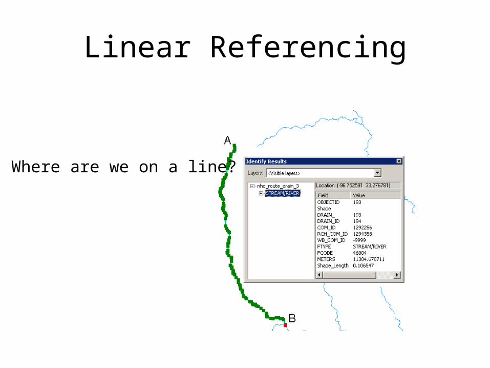
Linear Referencing
Where are we on a line?

My Streams are really long…
Use ReachID to link many Hydro Edges together into one River

Addressing
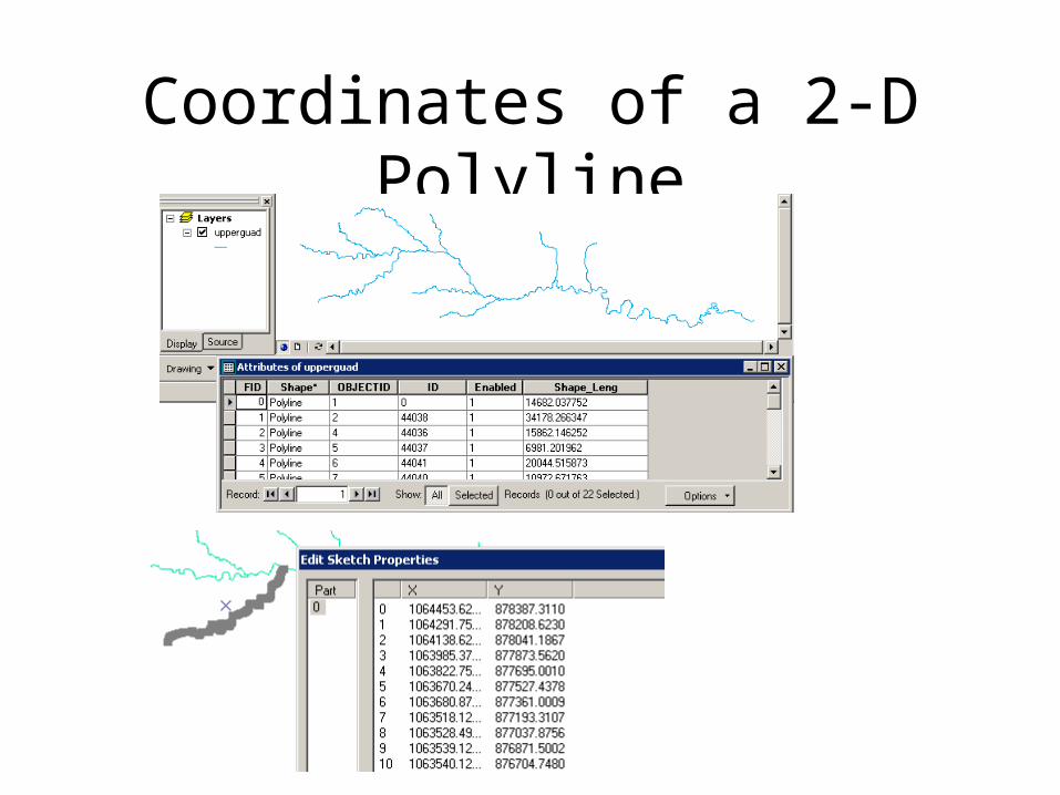
Coordinates of a 2-D Polyline

Coordinates of a 2-D Polyline M

Setting Line Measure

Proportional Aliasing
Distance is measured Relative to the length of the line as a percentage0% – 100%

Setting Percent Measure
pMSeg.SetAndInterpolateMsBetween 0, 100
pMSeg.SetAndInterpolateMsBetween 100, 0
0 – 100 going upstream 0 – 100 going downstream

Distances from Upper End in Meters

0%
100%
Percent distance frombottom end of reach

Measure in kilometers
pMSeg.SetAndInterpolateMsBetween 0, ([Shape_Length] /1000)
Measure in km frombottom end of line(like river miles or Kilometers)

Point and Line Events
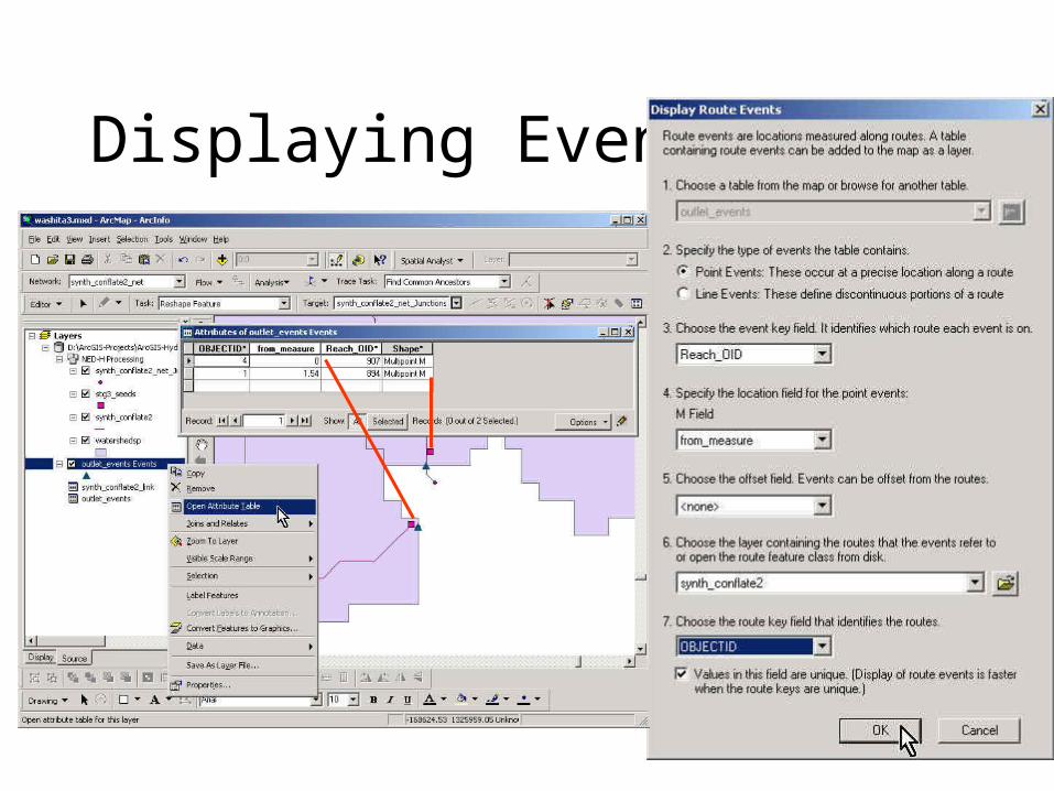
Displaying Events

Summary Concepts
• A network is a connected set of points (junctions) and lines (edges) that supports tracing functions– Three data model components
• Geographic (x,y,z)
• Logical (point-line topology connections)
• Addressing (position m along the line)
• Features can be geometrically connected (network) or relationally connected (HydroID)

Summary Concepts (2)
• Land-water connections– Area flows to a line model (one Catchment is
connected to one flowline) – used in NHDPlus and by Arc Hydro DrainID connections
– Area flows to line at a point model (one Watershed contains many streams that drain to a Junction at the outlet) – used in Arc Hydro where HydroID of the HydroJunction is JunctionID of the Watershed
Summary Concepts (3)
• Linear referencing can be used to locate point and line “events” on a network
• This is like (x,y) event themes that you used earlier to map stream gage locations in geographic space
• With linear referencing the locations are in “network space” but can be converted to regular features if necessary