Embed Size (px)
Citation preview
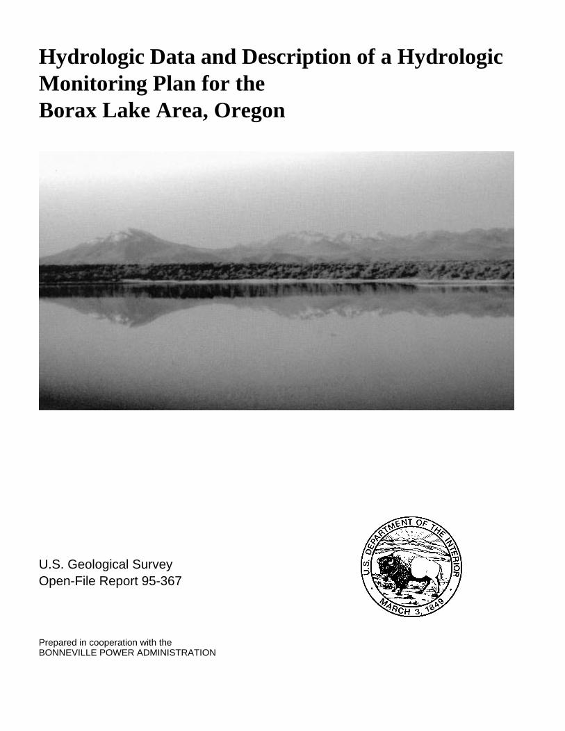
Hydrologic Data and Description of a HydrologicMonitoring Plan for theBorax Lake Area, Oregon
U.S. Geological SurveyOpen-File Report 95-367
Prepared in cooperation with theBONNEVILLE POWER ADMINISTRATION
Hydrologic Data and Description of a HydrologicMonitoring Plan for theBorax Lake Area, Oregon
By TIFFANY RAE SCHNEIDER and WILLIAM D. MCFARLAND
U.S. Geological SurveyOpen-File Report 95-367
Prepared in cooperation with theBONNEVILLE POWER ADMINISTRATION
Portland, Oregon1995
083000
U.S. DEPARTMENT OF THE INTERIORBRUCE BABBITT, Secretary
U.S. GEOLOGICAL SURVEYGORDON P. EATON, Director
The use of trade, product, or firm names in this publication is for descriptivepurposes only and does not imply endorsement by the U.S. Government.
For additional information write to:
District ChiefU.S. Geological Survey, WRD10615 S.E. Cherry Blossom DrivePortland, Oregon 97216
Copies of this report can bepurchased from:
U.S. Geological SurveyEarth Science Information CenterOpen-File Reports SectionBox 25286, MS 517Denver Federal CenterDenver, CO 80225
—12:59:47: iii iiU
.....20
.
CONTENTS
Abstract .......................................................................................................................................................................................1Introduction.................................................................................................................................................................................2
Background .......................................................................................................................................................................2Purpose and Scope ............................................................................................................................................................4
Data-Collection Methods ............................................................................................................................................................6Water Levels .....................................................................................................................................................................6Discharge ..........................................................................................................................................................................6Field Water-Quality Data..................................................................................................................................................6Lake Measurements ..........................................................................................................................................................7Positioning ........................................................................................................................................................................7Bathymetry........................................................................................................................................................................7Underwater Video Photography........................................................................................................................................7
Hydrologic Data..........................................................................................................................................................................7Lake...................................................................................................................................................................................7Springs ..............................................................................................................................................................................9Wells .................................................................................................................................................................................9Water Quality ..................................................................................................................................................................15
Monitoring Plan ........................................................................................................................................................................15Borax Lake......................................................................................................................................................................15
Inflow/Discharge...................................................................................................................................................15Lake Stage.............................................................................................................................................................17Evaporation ...........................................................................................................................................................18Water Temperature and Specific Conductance.....................................................................................................18Water-Quality Sampling and Analysis .................................................................................................................19
Shallow Ground Water Adjacent to Borax Lake ............................................................................................................19Ground-Water Levels............................................................................................................................................19
North Borax Lake Spring Group 1..................................................................................................................................20Water Temperature and Specific Conductance.....................................................................................................20Water-Quality Sampling and Analysis .................................................................................................................20
Wells ...............................................................................................................................................................................20Construction ..........................................................................................................................................................20Water Levels, Temperature, and Discharge..........................................................................................................20Water-Quality Sampling and Analysis .................................................................................................................20
Deep Geothermal Well(s) ...............................................................................................................................................20Review Available Geothermal Well, Geologic Map, and Geophysical Data ..................................................
Selected References ..................................................................................................................................................................21Appendix—Physical Parameters, Chemical Constituents, and Isotopes for Monitoring Sites ...............................................23
083000—12:59:47: iv
.......
FIGURES
1– 2. Maps showing:
1. Location of Borax Lake study area, Oregon ...............................................................................................................3
2. Location in Oregon of Borax Lake Spring Group, North Borax Lake Spring Group 1,and benchmarks and main vent at Borax Lake............................................................................................................5
3. Bathymetric map of main vent, Borax Lake, Oregon .......................................................................................................8
4. Map showing location of North Borax Lake Spring Group 4, Oregon...........................................................................10
TABLES
1. Records of selected springs in the Pueblo Valley, Oregon .............................................................................................11
2. Records of selected wells in the Pueblo Valley, Oregon ................................................................................................16
3. Results of chemical analyses of water samples collected from the Borax Lake area, Oregon................................18
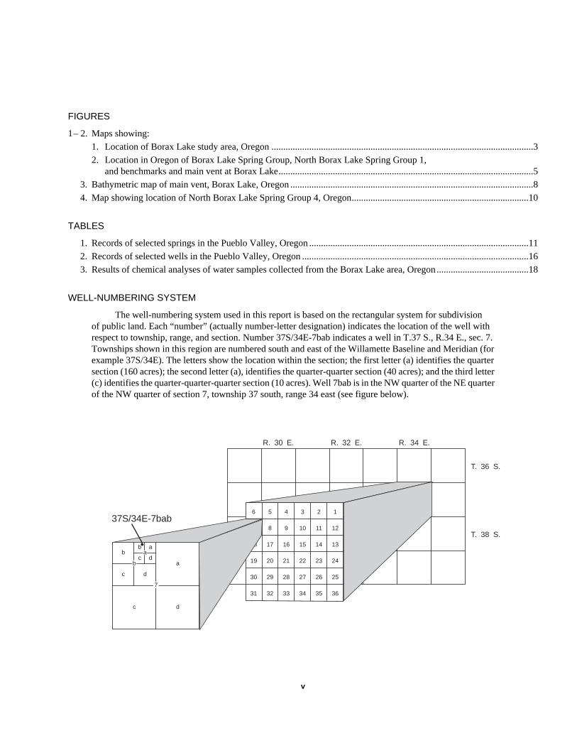
WELL-NUMBERING SYSTEM
The well-numbering system used in this report is based on the rectangular system for subdivisionof public land. Each “number” (actually number-letter designation) indicates the location of the well withrespect to township, range, and section. Number 37S/34E-7bab indicates a well in T.37 S., R.34 E., sec. 7.Townships shown in this region are numbered south and east of the Willamette Baseline and Meridian (forexample 37S/34E). The letters show the location within the section; the first letter (a) identifies the quartersection (160 acres); the second letter (a), identifies the quarter-quarter section (40 acres); and the third letter(c) identifies the quarter-quarter-quarter section (10 acres). Well 7bab is in the NW quarter of the NE quarterof the NW quarter of section 7, township 37 south, range 34 east (see figure below).
1
12
13
24
25
36
2
11
14
23
26
35
3
10
15
22
27
34
4
9
16
21
28
33
5
8
17
20
29
32
6
7
18
19
30
31
T. 36 S.
T. 38 S.
R. 30 E. R. 32 E. R. 34 E.
37S/34E-7bab
a
a
dc
bab
c d
dc
7
b
083000—12:59:47: v
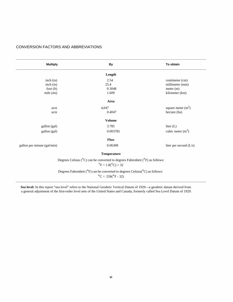
CONVERSION FACTORS AND ABBREVIATIONS
Multiply By To obtain
Length
inch (in) 2.54 centimeter (cm)inch (in) 25.4 millimeter (mm)foot (ft) 0.3048 meter (m)
mile (mi) 1.609 kilometer (km)
Area
acre 4,047 square meter (m2)acre 0.4047 hectare (ha)
Volume
gallon (gal) 3.785 liter (L)
gallon (gal) 0.003785 cubic meter (m3)
Flow
gallon per minute (gal/min) 0.06308 liter per second (L/s)
Temperature
Degrees Celsius (°C) can be converted to degrees Fahrenheit (°F) as follows:
°F = 1.8(°C) + 32
Degrees Fahrenheit (°F) can be converted to degrees Celsius(°C) as follows:
°C = .556(°F - 32)
Sea level: In this report “sea level” refers to the National Geodetic Vertical Datum of 1929—a geodetic datum derived froma general adjustment of the first-order level nets of the United States and Canada, formerly called Sea Level Datum of 1929.
083000—12:59:47: vi


Hydrologic Data and Descriptionof a Hydrologic Monitoring Planfor the Borax Lake Area, Oregon
By Tiffany Rae Schneider and William D. McFarland
in-
t
l.
Abstract
Borax Lake is located in southeasternOregon, within the Alvord Valley Known Geo-thermal Resource Area. Borax Lake is a largehot spring; there are more than 50 smaller hotsprings within about one-half mile to the northof the lake. Several geothermal exploration wellshave been drilled near Borax Lake, and there isconcern that development of the geothermalresources could affect the lake and nearby hotsprings. A factor to consider in developing theresource is that the Borax Lake chub is an endangered species of fish that is found exclusively inBorax Lake.
This study was designed to collect basichydrologic data to develop a long-term moni-toring plan. Baseline data, collected before geothermal production wells are used extensively,will provide an understanding of natural trendsand will help identify change caused by development.
Basic data collected during reconnaissancefield visits to the area included spring tempera-tures, specific conductances, and discharge;field measurements in wells included water-level measurements and temperature, specificconductance, and discharge measurements inflowing wells. The study of the Borax Lake area
8/30/00–12:59:47 1
-
-
-
included depth and temperature measurementsthe vent area of the lake, point velocity measurements, underwater video photography, and anevaluation of methods to measure discharge fromthe lake. Water-quality samples were collected aBorax Lake, one hot spring, and one flowingwell.
Information from field visits was used todevelop a monitoring plan. The plan wouldinclude monitoring Borax Lake by measuringdischarge, stage, evaporation, temperature, andspecific conductance; water-quality samplingand analysis; and monitoring shallow ground-water levels near Borax Lake using shallowpiezometers. Minimally, one hot spring in NorthBorax Lake Spring Group 1 would be monitoredfor temperature and specific conductance andsampled for water-quality analysis. In addition,two flowing wells would be monitored for waterlevels, temperature, specific conductance, anddischarge and sampled for water-qualityanalysis. The construction characteristics ofthese wells must be verified before long-termdata collection begins. In the future, it may behelpful to monitor shallow and (or) deepobservation wells drilled into the thermal aquiferto understand the possible effects of geothermadevelopment on Borax Lake and nearby springs
ice
han
yy
f
dnce
e
sw
of
ende
ea
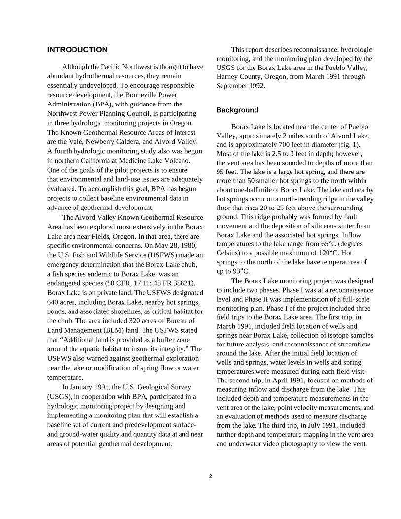
INTRODUCTION
Although the Pacific Northwest is thought to haveabundant hydrothermal resources, they remainessentially undeveloped. To encourage responsibleresource development, the Bonneville PowerAdministration (BPA), with guidance from theNorthwest Power Planning Council, is participatingin three hydrologic monitoring projects in Oregon.The Known Geothermal Resource Areas of interestare the Vale, Newberry Caldera, and Alvord Valley.A fourth hydrologic monitoring study also was begunin northern California at Medicine Lake Volcano.One of the goals of the pilot projects is to ensurethat environmental and land-use issues are adequaevaluated. To accomplish this goal, BPA has begunprojects to collect baseline environmental data inadvance of geothermal development.
The Alvord Valley Known Geothermal ResourceArea has been explored most extensively in the BoraLake area near Fields, Oregon. In that area, there aspecific environmental concerns. On May 28, 1980,the U.S. Fish and Wildlife Service (USFWS) made aemergency determination that the Borax Lake chuba fish species endemic to Borax Lake, was anendangered species (50 CFR, 17.11; 45 FR 35821)Borax Lake is on private land. The USFWS designate640 acres, including Borax Lake, nearby hot springsponds, and associated shorelines, as critical habitatthe chub. The area included 320 acres of Bureau ofLand Management (BLM) land. The USFWS statedthat “Additional land is provided as a buffer zonearound the aquatic habitat to insure its integrity.” ThUSFWS also warned against geothermal explorationear the lake or modification of spring flow or watertemperature.
In January 1991, the U.S. Geological Survey(USGS), in cooperation with BPA, participated in ahydrologic monitoring project by designing andimplementing a monitoring plan that will establish abaseline set of current and predevelopment surfaceand ground-water quality and quantity data at and neareas of potential geothermal development.
8/30/00–12:59:47 2
tely
xre
n,
.d,for
en
-ar
This report describes reconnaissance, hydrologmonitoring, and the monitoring plan developed by thUSGS for the Borax Lake area in the Pueblo Valley,Harney County, Oregon, from March 1991 throughSeptember 1992.
Background
Borax Lake is located near the center of PuebloValley, approximately 2 miles south of Alvord Lake,and is approximately 700 feet in diameter (fig. 1).Most of the lake is 2.5 to 3 feet in depth; however,the vent area has been sounded to depths of more t95 feet. The lake is a large hot spring, and there aremore than 50 smaller hot springs to the north withinabout one-half mile of Borax Lake. The lake and nearbhot springs occur on a north-trending ridge in the vallefloor that rises 20 to 25 feet above the surroundingground. This ridge probably was formed by faultmovement and the deposition of siliceous sinter fromBorax Lake and the associated hot springs. Inflowtemperatures to the lake range from 65°C (degreesCelsius) to a possible maximum of 120°C. Hotsprings to the north of the lake have temperatures oup to 93°C.
The Borax Lake monitoring project was designeto include two phases. Phase I was at a reconnaissalevel and Phase II was implementation of a full-scalemonitoring plan. Phase I of the project included threfield trips to the Borax Lake area. The first trip, inMarch 1991, included field location of wells andsprings near Borax Lake, collection of isotope samplefor future analysis, and reconnaissance of streamfloaround the lake. After the initial field location ofwells and springs, water levels in wells and springtemperatures were measured during each field visit.The second trip, in April 1991, focused on methods measuring inflow and discharge from the lake. Thisincluded depth and temperature measurements in thvent area of the lake, point velocity measurements, aan evaluation of methods used to measure dischargfrom the lake. The third trip, in July 1991, includedfurther depth and temperature mapping in the vent arand underwater video photography to view the vent.
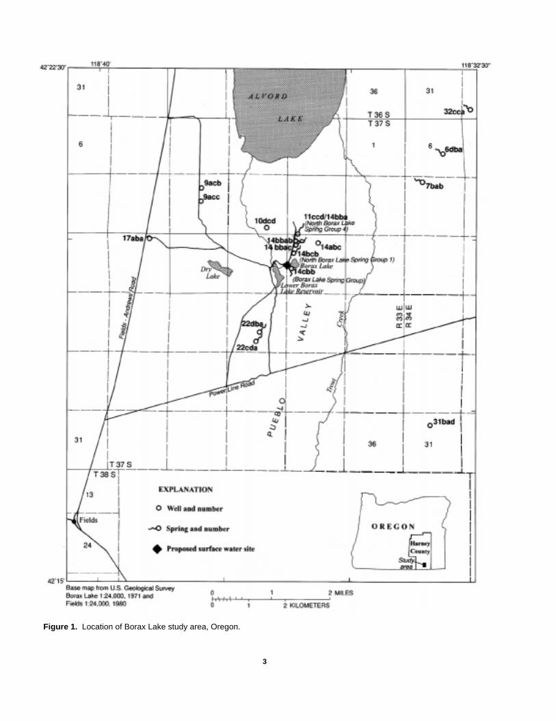
Figure 1. Location of Borax Lake study area, Oregon.
8/30/00–12:59:47 3

e
l
er
sur
ke
ta
n
e,
the
g
gs
d
The feasibility of continuous velocity measurementsand the use of continuous monitoring sites in the lakvent at approximately a 90-foot depth was assessedIn addition, consideration was given to monitoring athe nearest hot spring located to the north, and a watquality sample of inflowing vent water was collectedfor analysis (sample collected by Robert Mariner,USGS, Menlo Park, California). Information fromthese three field trips allowed development of acomprehensive monitoring plan. In the event ofdevelopment, this plan was to be implemented inPhase II of the study.
Borax Lake is contained by a narrow rim ofsiliceous sinter that is 3 to 5 feet in width and is anaverage of less than 1 foot high above the lake surfacFrom the crest of this rim, the land surface slopes awfrom the lake in all directions. As a result, no surfacewater runoff flows into the lake. However, this rimhas been naturally breached in several places by waaction and has been breached by man to irrigate lanfor cattle grazing. Approximately 8 to 10 channelsallow water to discharge from the lake. Some of thechannels flow without control and others have been“sandbagged” to regulate the flow and to maintain thlevel of the lake. Most of these channels flow out of thnortheastern shore of the lake; however, two majorchannels are present on the western edge of the lakone of these is the channel that at one time suppliedwater to Lower Borax Lake Reservoir to the west.During much of the study period, Lower Borax LakeReservoir was dry. However, the water level at BoraLake is kept at a relatively high stage; therefore, watealso seeps through grassy areas on the western ansouthern rim of the lake. Although an estimate of ruoff from Borax Lake was made during the March 199field trip, this estimate was of unknown accuracybecause of the many avenues of discharge.
During field reconnaissance, it was evident thaground-water discharge also occurs from the lake. Twto three hundred feet southwest of the lake, in the arof the Borax Lake Spring Group (fig. 2), cold watersprings with temperatures and specific conductancesimilar to those of the lake were discharging at ratesof 1 to 2 gallons per minute. These springs may be result of raising the lake level and diversion of some othe lake water to a large pond southwest of the lake
8/30/00–12:59:47 4
e.
ter-
e.ay-
ved
se
ee
e—
xr
dn-1
to
ea
s
af.
There are also several areas around the lake wherdiffuse ground-water seepage occurs.
Variations in the temperature of the geothermawater entering the lake are evident from observedfish kills that have occurred since about 1980. Thelargest fish kill was noted in July 1987, when 1,500to 2,000 fish were apparently killed from increasedinflow temperatures (Denny Seymour, BLM, writtencommun., 1991). These events indicate that therehave been significant increases in temperature undnatural conditions.
The longest-term monitoring at Borax Lake habeen conducted by BLM employees (Denny Seymoof Portland, Oregon and Terry Geisler of Burns,Oregon). Their work has included operation of aweather station on the south side of the lake, aswell as continuous measurements of lake watertemperature. Periodic manual measurements of latemperature around the lake shore also have beencollected on a long-term basis.
Purpose and Scope
The purpose of this report is to present the dacollected in Phase I of the project and describe themonitoring plan for Phase II of the project. A limitedamount of data was collected for Phase II of theproject, because BPA delegated most of the work oBorax Lake to BLM. The data that were collected bythe USGS are included in this report. This initialshort data record, collected during this study on thhydrology, water chemistry, and biology of the areais not sufficient to define baseline conditions for thearea and may not be adequate to assess change inhydrologic and biologic systems in the future whengeothermal development occurs. Additional dataare needed to establish natural ranges in hot sprintemperatures, discharges, and water-qualityparameters. Similar data are needed for cold sprinand wells in the area.
Phase I of the project (March 1991–September 1991) was of limited scope and involve(1) a literature and file search for existing wells,springs, hydrologic data, and technical reports; and
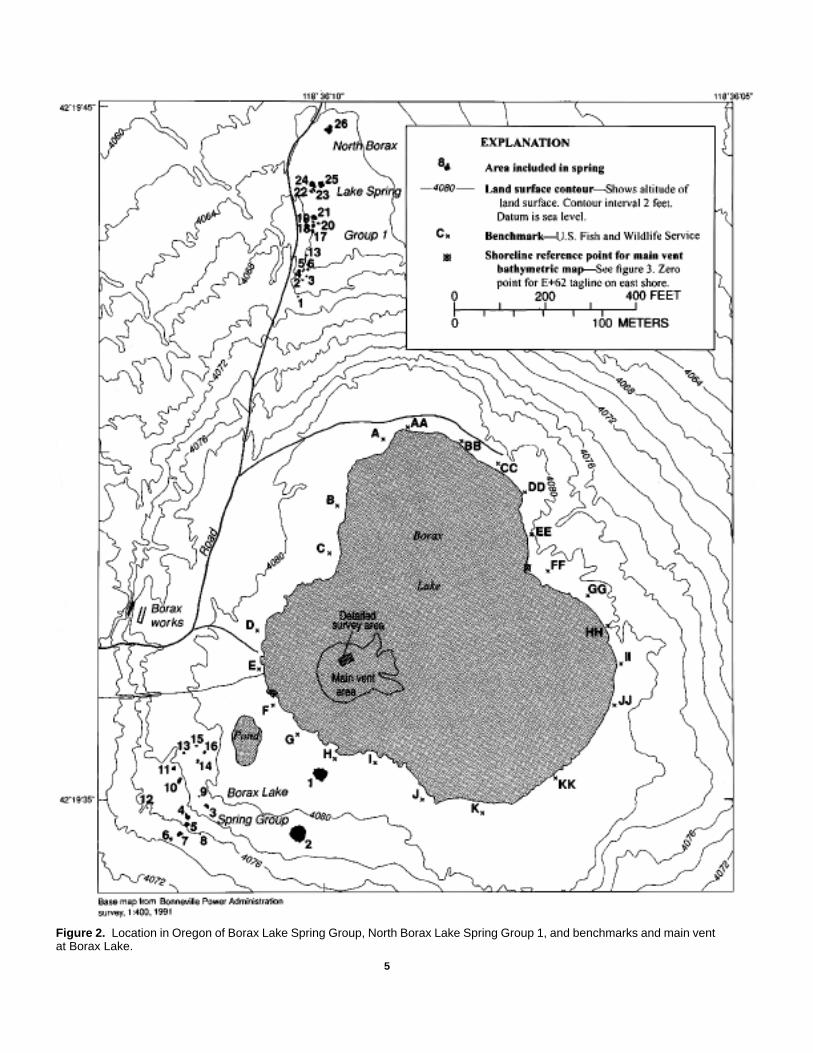
Figure 2. Location in Oregon of Borax Lake Spring Group, North Borax Lake Spring Group 1, and benchmarks and main ventat Borax Lake.
8/30/00–12:59:47 5
ItII
,d
l
s
g
et.
o
er
asf
ts
som
,.
(2) reconnaissance field work to locate hydrologicfeatures of interest, make initial measurements,and make other hydrologic observations. Findingsfrom Phase I of the project were used to developa detailed work plan for Phase II of the study tomonitor potential effects of geothermal develop-ment. At the end of Phase I, Phase II was not fullyimplemented because it appeared unlikely thatgeothermal development would occur. However,a limited network of wells and springs was monitoredthrough September 1992.
The objective of Phase II of the Borax Lakehydrologic monitoring program was to design andimplement plans to collect baseline environmentaldata prior to geothermal development in the area. was proposed that during fiscal year 1992, Phase monitoring would begin in the immediate vicinity(within approximately a 1-mile radius) of BoraxLake. Sites of interest included Borax Lake, theshallow ground-water system near Borax Lake(Borax Lake Spring Group), hot springs north ofBorax Lake (North Borax Lake Spring Group 1and Group 4), and wells 37S/33E-14abc and37S/33E-10dcd. Water levels in other field-locatedwells were also measured.
DATA-COLLECTION METHODS
Data were collected for the Borax Lake studyusing USGS standard methods. Where appropriatereferences for these standard methods are includein the following discussion.
Water Levels
Water levels in wells were collected using a steeengineer’s tape calibrated to hundredths of a foot.Two measurements were made within a few minuteof one another at each measurement site, and themeasurements were accepted only if they agreedwithin one-hundredth of a foot. Measuring pointand land-surface elevations were established usin1:24,000-scale topographic maps published by theUSGS.
8/30/00–12:59:48 6
Water levels in all wells in the study area wermade during static conditions during each field visiNone of the wells were used during the period ofstudy.
Flowing wells in the study area have beenflowing for many years and no attempt was made t“shut in” these wells for water-level measurement.Accurate discharge measurements were made,however, on flowing wells. Standard USGS water-level measurement methods can be found in Garband Koopman (1968).
Discharge
Discharge from flowing wells was measuredusing volumetric methods. Generally, a smallwooden flume that channeled the water into onedischarge point was placed on top of the well.Discharge was then measured using a bucket andstop watch. Discharge measurements from springgenerally were not made because of the difficulty ochanneling flow from the springs into one distinctdischarge point that could be measured. Thedischarge from many of the springs seeps into theground near their orifices.
Field Water-Quality Data
Temperature data were collected using adigital thermometer or a combination temperatureand specific conductance probe. These instrumenwere calibrated at the beginning of each day.The thermometer was checked using a mercurythermometer, and the specific conductance meterwas checked with conductivity standards thatbracketed the range of specific conductancesexpected in the field.
Samples were taken for analysis of major ionand stable isotopes. These samples were taken fr(1) the Borax Lake orifice at a depth of approxi-mately 90 feet, (2) the flowing well 37S/33E-14abcand (3) a hot spring in North Borax Spring Group 4Additional isotope samples were collected andarchived for later analysis.
et
dE
m
ith
,
f
o
,,
r
d
dy
.
Lake Measurements
Physical parameters of Borax Lake, includingwater velocities and lake depth (bathymetry), weremeasured on Borax Lake itself. The location of eachsampling point was established using taglines.
During the April 1991 visit, water velocities inthe lake were measured to determine the feasibility oinstalling an acoustic velocity meter in the vent of thelake to measure inflow of geothermal water. Thesemeasurements required using two measuring devicesa Marsh-McBirney electromagnetic velocity meterand a portable acoustic velocity meter. The Marsh-McBirney meter was used to measure vertical velocitieand the acoustic velocity meter was used to measurevelocities in the X and Y directions. These measure-ments were done for reconnaissance purposes only.
The amount, characteristics, and variability ofgeothermal water that flows into Borax Lake are poorlunderstood. Depth and temperature soundings indicathat a single main vent currently supplies water to thelake. Water enters the vent bottom at a depth of appromately 90 feet, but water may also enter the lake fromthe sides of the orifice. Flow into the vent is diffuse anturbulent and causes convective flow in the lake.
Positioning
The boat position and measuring locations wereestablished using a tagline that spanned the lake.Twenty-two USFWS benchmarks, located around theperimeter of the lake, were used to determine thelocation of the tagline anchor points along the rim ofthe lake. These benchmarks are shown in figure 2.The tagline used was made of galvanized steel andwas marked at 5-foot intervals with brass beads. Thetagline reel was placed on the west shore of the lake astretched across the lake to the east side. The two enpoints were located an equal distance southeast of thand the EE benchmarks (fig. 2).
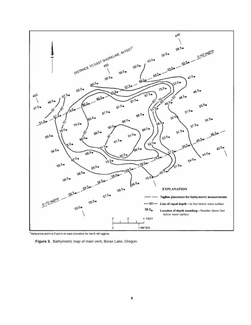
Bathymetry
Detailed bathymetry was done in the central orificof Borax Lake to help define the vent area (fig. 3). Thibathymetry was done by using two taglines aligned
8/30/00–12:59:48 7
f
—
s,
yte
xi-
d
ndd
e E
es
parallel to each other, approximately 10 feet apart(fig. 3). By using the double-tagline method, errorresulting from strong winds was minimized.If a single tagline is used there can be up to 2 or 3 feof error because of winds. The taglines shown infigure 3 were placed by using additional spacingfrom the original benchmarks in order to map themain vent area more accurately. For example, thedestination “E+60” means that the tagline was place60 feet southeast of the line between the E and the Ebenchmarks.
Gas bubbles that enter the lake from the bottoof the orifice of the vent area make using standarddepth sounding (sonar) equipment difficult; there-fore, all bathymetric measurements were made wa sounding weight and a stream-gaging reel.
Underwater Video Photography
The vent area of the lake was filmed usingan underwater video camera and a light source.The camera and light source were mounted in agalvanized pipe frame about 5 feet long, 2 feet wideand 2 feet tall. The camera was lowered from theboat (positioned with taglines) to the 90-foot depth othe central vent. During filming, images of the lakebottom that were observed from the boat were alsrecorded on video tape.
Underwater video photography showed flowfrom many small vents within the main orifice andin some places, an extremely irregular bottom. Alsogas bubbles discharged with the geothermal watefrom the orifices and floated to the lake surface.
HYDROLOGIC DATA
Lake
Temperatures measured in Borax Lake rangefrom 18°C at the lake’s edge to more than 93°Cwhere geothermal waters enter the bottom of thevent area. Temperatures measured during this stumay not be as high as those reported by others(Denny Seymour, BLM, written commun., 1991),because a 50-pound weight which would not fit intosmaller orifices at the bottom of the lake was used
8/
Figure 3. Bathymetric map of main vent, Borax Lake, Oregon.
30/00–12:59:48 8

ine
aa
ll
ys
,s
n,-
-
ns
e
r
psedeis
This 50-pound weight was used to assure that thetemperature and acoustic velocity probes went intothe orifice vertically.
Velocity data were collected to determine thefeasibility of using an acoustic velocity meter in thevent area to monitor inflow into the lake. The velocitydata were collected at individual points across thelake and at various depths. The movement of waterthe lake tends to be convective. In some parts of thvent, turbulent flow is evident. Measured velocitiesranged from 0 to more than 15 centimeters persecond. In the bottom of the vent, the direction of flowrotated in all directions. Observations made laterusing the underwater video camera showed that gbubbles enter the lake in the bottom of the vent areIndividual measurements of flow, taken during aperiod of several hours, proved difficult to interpret.
The velocity measurements and underwatervideo photography also indicated that water flowsinto the lake from many small holes, rather than fromone large hole at the bottom of the vent. These smaholes occur near the bottom of the main vent, as weas along the walls of the main vent.
Springs
The hot springs near Borax Lake exist in manforms (figs. 2 and 4), and the water in these springhas temperatures that vary from 5°C to 100°C.The springs can be placed in five groups fordiscussion purposes. These groups include BoraxLake Spring Group southwest of Borax Lake andfour spring groups north of Borax Lake calledNorth Borax Lake Spring Groups 1, 2, 3, and 4.The Borax Lake Spring Group is a group of warmwater springs which may be caused primarily byground-water seepage from Borax Lake. Howeverthe North Borax Spring Groups include some springthat have temperatures approaching 100°C; watertemperatures in the hot springs at the spring orificecan vary during a 24-hour period by as much as 10°C.
8/30/00–12:59:48 9
s.
ll
In some cases, temperatures can vary inversely ihot springs adjacent to one another. For exampleone of the two springs may have a higher temperature one day, but the next day the other springmay have the higher temperature. Because thetemperature of some springs changes with atmospheric temperature, the temperature of thosesprings are changing constantly.
Most springs in the Borax Lake Spring Groupare essentially inactive; however, a few smallersprings (8, 9, and 12) in the spring group have beeobserved to discharge approximately 1 to 2 gallonof water per minute from 3- to 6-inch orifices.The specific conductance of the water in these thresprings (2,200–2,470µS/cm [microsiemens percentimeter]) and the specific conductance of watein Borax Lake (2,140µS/cm) was similar onMarch 21, 1991, whereas the other springs in thegroup could have significantly higher specificconductances (table 1). These different specificconductances could indicate different sources ofthermal water to the springs.
Data collection on springs north of Borax Lakefocused on groups 1 and 4. These two spring grouhave more than 20 active springs that were observduring this study. Hot springs in groups 2 and 3 arfewer in number and were not measured during thstudy.
Wells
Six wells were field located in the PuebloValley near Borax Lake. Two of the wells nearestthe lake are warm flowing wells. Well 37S/33E-14abc (fig. 1) discharges 17 to 25 gallons perminute. The well-water temperature rangesconsistently from 56 to 58°C, and specificconductance has been measured between about1,800 and 2,100µS/cm. Well 37S/33E-10dcd(fig. 1) discharges 28 to 55 gallons per minute,has a consistent temperature of 16°C, and ameasured specific conductance of between250 and 281µS/cm. No attempt was made tomeasure static water levels in either flowing well.
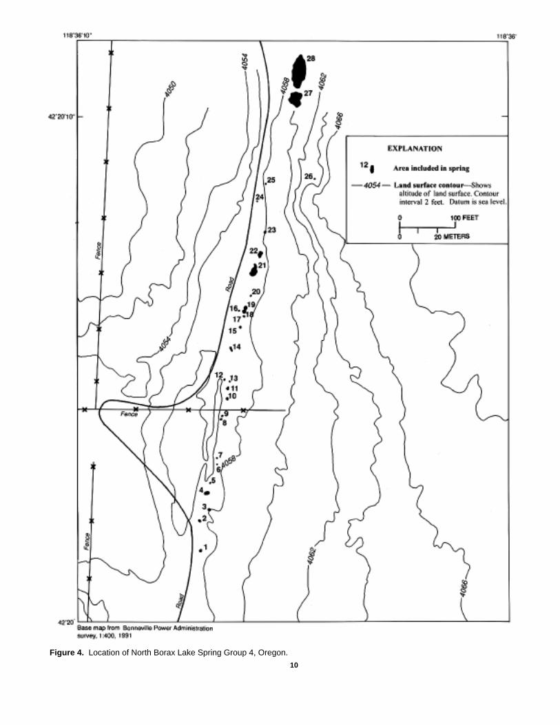
Figure 4. Location of North Borax Lake Spring Group 4, Oregon.
8/30/00–12:59:48 10
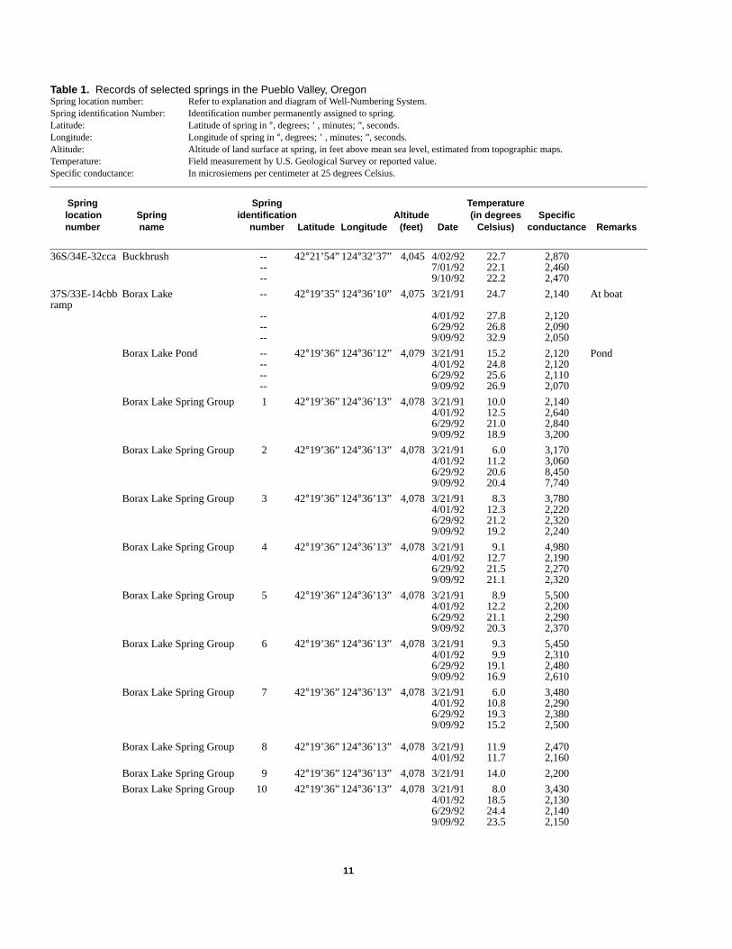
Table 1. Records of selected springs in the Pueblo Valley, OregonSpring location number: Refer to explanation and diagram of Well-Numbering System.Spring identification Number: Identification number permanently assigned to spring.Latitude: Latitude of spring in°, degrees; ’ , minutes; ”, seconds.Longitude: Longitude of spring in°, degrees; ’ , minutes; ”, seconds.Altitude: Altitude of land surface at spring, in feet above mean sea level, estimated from topographic maps.Temperature: Field measurement by U.S. Geological Survey or reported value.Specific conductance: In microsiemens per centimeter at 25 degrees Celsius.
Spring Spring Temperaturelocation Spring identification Altitude (in degrees Specificnumber name number Latitude Longitude (feet) Date Celsius) conductance Remarks
36S/34E-32cca Buckbrush -- 42°21’54” 124°32’37” 4,045 4/02/92 22.7 2,870-- 7/01/92 22.1 2,460-- 9/10/92 22.2 2,470
37S/33E-14cbb Borax Lake -- 42°19’35” 124°36’10” 4,075 3/21/91 24.7 2,140 At boatramp
-- 4/01/92 27.8 2,120-- 6/29/92 26.8 2,090-- 9/09/92 32.9 2,050
Borax Lake Pond -- 42°19’36” 124°36’12” 4,079 3/21/91 15.2 2,120 Pond-- 4/01/92 24.8 2,120-- 6/29/92 25.6 2,110-- 9/09/92 26.9 2,070
Borax Lake Spring Group 1 42°19’36” 124°36’13” 4,078 3/21/91 10.0 2,1404/01/92 12.5 2,6406/29/92 21.0 2,8409/09/92 18.9 3,200
Borax Lake Spring Group 2 42°19’36” 124°36’13” 4,078 3/21/91 6.0 3,1704/01/92 11.2 3,0606/29/92 20.6 8,4509/09/92 20.4 7,740
Borax Lake Spring Group 3 42°19’36” 124°36’13” 4,078 3/21/91 8.3 3,7804/01/92 12.3 2,2206/29/92 21.2 2,3209/09/92 19.2 2,240
Borax Lake Spring Group 4 42°19’36” 124°36’13” 4,078 3/21/91 9.1 4,9804/01/92 12.7 2,1906/29/92 21.5 2,2709/09/92 21.1 2,320
Borax Lake Spring Group 5 42°19’36” 124°36’13” 4,078 3/21/91 8.9 5,5004/01/92 12.2 2,2006/29/92 21.1 2,2909/09/92 20.3 2,370
Borax Lake Spring Group 6 42°19’36” 124°36’13” 4,078 3/21/91 9.3 5,4504/01/92 9.9 2,3106/29/92 19.1 2,4809/09/92 16.9 2,610
Borax Lake Spring Group 7 42°19’36” 124°36’13” 4,078 3/21/91 6.0 3,4804/01/92 10.8 2,2906/29/92 19.3 2,3809/09/92 15.2 2,500
Borax Lake Spring Group 8 42°19’36” 124°36’13” 4,078 3/21/91 11.9 2,4704/01/92 11.7 2,160
Borax Lake Spring Group 9 42°19’36” 124°36’13” 4,078 3/21/91 14.0 2,200
Borax Lake Spring Group 10 42°19’36” 124°36’13” 4,078 3/21/91 8.0 3,4304/01/92 18.5 2,1306/29/92 24.4 2,1409/09/92 23.5 2,150
8/30/00–12:59:48 11
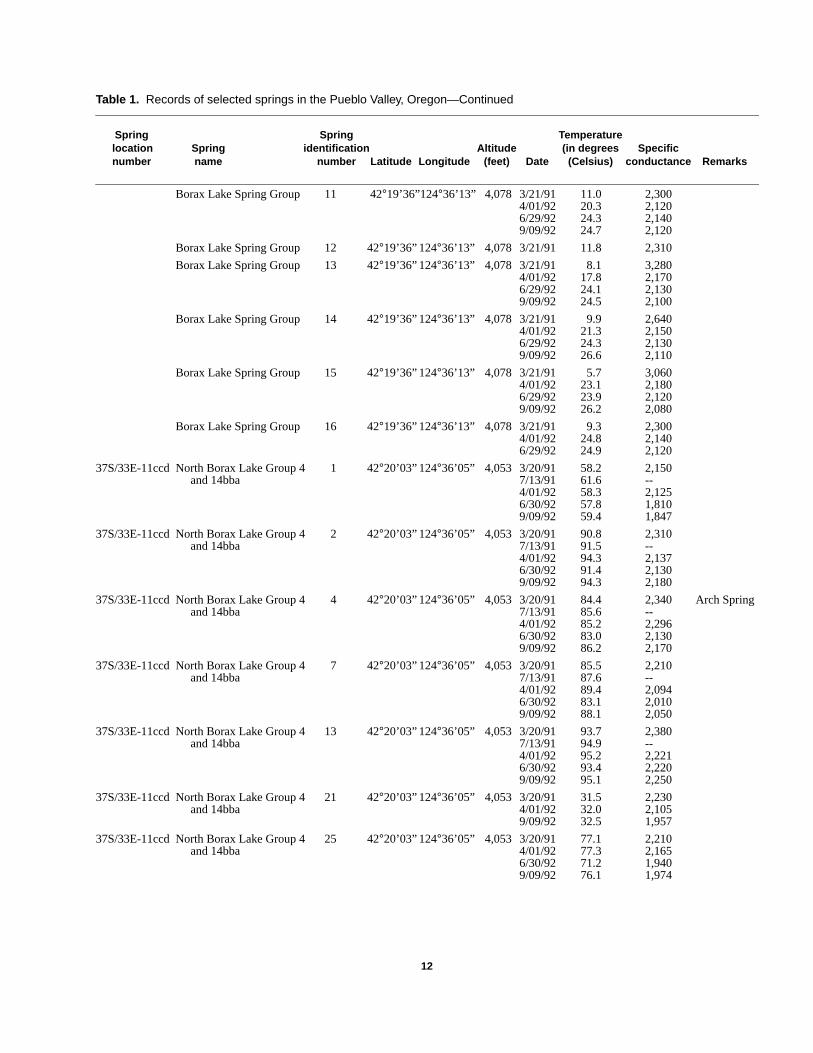
Table 1. Records of selected springs in the Pueblo Valley, Oregon—Continued
Spring Spring Temperaturelocation Spring identification Altitude (in degrees Specificnumber name number Latitude Longitude (feet) Date (Celsius) conductance Remarks
Borax Lake Spring Group 11 42°19’36”124°36’13” 4,078 3/21/91 11.0 2,3004/01/92 20.3 2,1206/29/92 24.3 2,1409/09/92 24.7 2,120
Borax Lake Spring Group 12 42°19’36” 124°36’13” 4,078 3/21/91 11.8 2,310
Borax Lake Spring Group 13 42°19’36” 124°36’13” 4,078 3/21/91 8.1 3,2804/01/92 17.8 2,1706/29/92 24.1 2,1309/09/92 24.5 2,100
Borax Lake Spring Group 14 42°19’36” 124°36’13” 4,078 3/21/91 9.9 2,6404/01/92 21.3 2,1506/29/92 24.3 2,1309/09/92 26.6 2,110
Borax Lake Spring Group 15 42°19’36” 124°36’13” 4,078 3/21/91 5.7 3,0604/01/92 23.1 2,1806/29/92 23.9 2,1209/09/92 26.2 2,080
Borax Lake Spring Group 16 42°19’36” 124°36’13” 4,078 3/21/91 9.3 2,3004/01/92 24.8 2,1406/29/92 24.9 2,120
37S/33E-11ccd North Borax Lake Group 4 1 42°20’03” 124°36’05” 4,053 3/20/91 58.2 2,150and 14bba 7/13/91 61.6 --
4/01/92 58.3 2,1256/30/92 57.8 1,8109/09/92 59.4 1,847
37S/33E-11ccd North Borax Lake Group 4 2 42°20’03” 124°36’05” 4,053 3/20/91 90.8 2,310and 14bba 7/13/91 91.5 --
4/01/92 94.3 2,1376/30/92 91.4 2,1309/09/92 94.3 2,180
37S/33E-11ccd North Borax Lake Group 4 4 42°20’03” 124°36’05” 4,053 3/20/91 84.4 2,340 Arch Springand 14bba 7/13/91 85.6 --
4/01/92 85.2 2,2966/30/92 83.0 2,1309/09/92 86.2 2,170
37S/33E-11ccd North Borax Lake Group 4 7 42°20’03” 124°36’05” 4,053 3/20/91 85.5 2,210and 14bba 7/13/91 87.6 --
4/01/92 89.4 2,0946/30/92 83.1 2,0109/09/92 88.1 2,050
37S/33E-11ccd North Borax Lake Group 4 13 42°20’03” 124°36’05” 4,053 3/20/91 93.7 2,380and 14bba 7/13/91 94.9 --
4/01/92 95.2 2,2216/30/92 93.4 2,2209/09/92 95.1 2,250
37S/33E-11ccd North Borax Lake Group 4 21 42°20’03” 124°36’05” 4,053 3/20/91 31.5 2,230and 14bba 4/01/92 32.0 2,105
9/09/92 32.5 1,957
37S/33E-11ccd North Borax Lake Group 4 25 42°20’03” 124°36’05” 4,053 3/20/91 77.1 2,210and 14bba 4/01/92 77.3 2,165
6/30/92 71.2 1,9409/09/92 76.1 1,974
8/30/00–12:59:48 12
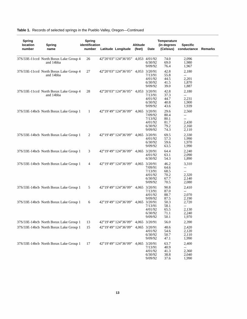
Table 1. Records of selected springs in the Pueblo Valley, Oregon—Continued
Spring Spring Temperaturelocation Spring identification Altitude (in degrees Specificnumber name number Latitude Longitude (feet) Date (Celsius) conductance Remarks
37S/33E-11ccd North Borax Lake Group 4 26 42°20’03” 124°36’05” 4,053 4/01/92 74.0 2,096and 14bba 6/30/92 69.0 1,980
9/09/92 76.4 1,967
37S/33E-11ccd North Borax Lake Group 4 27 42°20’03” 124°36’05” 4,053 3/20/91 42.8 2,180and 14bba 7/13/91 55.8 --
4/01/92 44.5 2,2016/30/92 41.5 1,8709/09/92 39.0 1,887
37S/33E-11ccd North Borax Lake Group 4 28 42°20’03” 124°36’05” 4,053 3/20/91 42.8 2,180and 14bba 7/13/91 37.3 --
4/01/92 44.7 2,2316/30/92 40.8 1,9009/09/92 43.6 1,939
37S/33E-14bcb North Borax Lake Group 1 1 42°19’49” 124°36’09” 4,065 3/20/91 29.6 2,5607/09/92 80.4 --7/13/92 80.1 --4/01/92 81.7 2,4306/30/92 79.2 2,1609/09/92 74.3 2,110
37S/33E-14bcb North Borax Lake Group 1 2 42°19’49” 124°36’09” 4,065 3/20/91 69.5 2,3304/01/92 57.3 1,9906/30/92 59.6 1,9709/09/92 63.5 1,990
37S/33E-14bcb North Borax Lake Group 1 3 42°19’49” 124°36’09” 4,065 3/20/91 64.4 2,2404/01/92 63.1 2,0906/30/92 54.3 1,890
37S/33E-14bcb North Borax Lake Group 1 4 42°19’49” 124°36’09” 4,065 3/20/91 46.2 3,3107/09/91 64.6 --7/13/91 68.5 --4/01/92 70.2 2,3206/30/92 67.7 2,1409/09/92 70.5 2,080
37S/33E-14bcb North Borax Lake Group 1 5 42°19’49” 124°36’09” 4,065 3/20/91 90.8 2,4107/13/91 87.0 --4/01/92 88.7 2,0709/09/92 87.5 2,190
37S/33E-14bcb North Borax Lake Group 1 6 42°19’49” 124°36’09” 4,065 3/20/91 50.3 2,7207/13/91 58.1 --4/01/92 65.5 2,1306/30/92 71.1 2,2409/09/92 50.1 1,970
37S/33E-14bcb North Borax Lake Group 1 13 42°19’49” 124°36’09” 4,065 3/20/91 56.0 2,390
37S/33E-14bcb North Borax Lake Group 1 15 42°19’49” 124°36’09” 4,065 3/20/91 48.6 2,4204/01/92 54.6 2,1206/30/92 50.7 2,1109/09/92 47.1 1,990
37S/33E-14bcb North Borax Lake Group 1 17 42°19’49” 124°36’09” 4,065 3/20/91 63.7 2,4007/13/91 40.9 --4/01/92 41.3 2,3606/30/92 38.8 2,0409/09/92 37.6 1,990
8/30/00–12:59:48 13
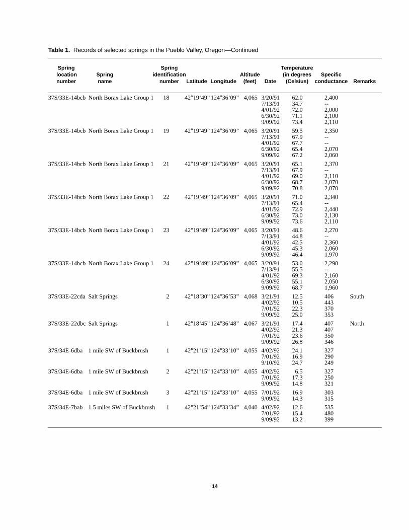
Table 1. Records of selected springs in the Pueblo Valley, Oregon—Continued
Spring Spring Temperaturelocation Spring identification Altitude (in degrees Specificnumber name number Latitude Longitude (feet) Date (Celsius) conductance Remarks
37S/33E-14bcb North Borax Lake Group 1 18 42°19’49” 124°36’09” 4,065 3/20/91 62.0 2,4007/13/91 34.7 --4/01/92 72.0 2,0006/30/92 71.1 2,1009/09/92 73.4 2,110
37S/33E-14bcb North Borax Lake Group 1 19 42°19’49” 124°36’09” 4,065 3/20/91 59.5 2,3507/13/91 67.9 --4/01/92 67.7 --6/30/92 65.4 2,0709/09/92 67.2 2,060
37S/33E-14bcb North Borax Lake Group 1 21 42°19’49” 124°36’09” 4,065 3/20/91 65.1 2,3707/13/91 67.9 --4/01/92 69.0 2,1106/30/92 68.7 2,0709/09/92 70.8 2,070
37S/33E-14bcb North Borax Lake Group 1 22 42°19’49” 124°36’09” 4,065 3/20/91 71.0 2,3407/13/91 65.4 --4/01/92 72.9 2,4406/30/92 73.0 2,1309/09/92 73.6 2,110
37S/33E-14bcb North Borax Lake Group 1 23 42°19’49” 124°36’09” 4,065 3/20/91 48.6 2,2707/13/91 44.8 --4/01/92 42.5 2,3606/30/92 45.3 2,0609/09/92 46.4 1,970
37S/33E-14bcb North Borax Lake Group 1 24 42°19’49” 124°36’09” 4,065 3/20/91 53.0 2,2907/13/91 55.5 --4/01/92 69.3 2,1606/30/92 55.1 2,0509/09/92 68.7 1,960
37S/33E-22cda Salt Springs 2 42°18’30” 124°36’53” 4,068 3/21/91 12.5 406 South4/02/92 10.5 4437/01/92 22.3 3709/09/92 25.0 353
37S/33E-22dbc Salt Springs 1 42°18’45” 124°36’48” 4,067 3/21/91 17.4 407 North4/02/92 21.3 4077/01/92 23.6 3509/09/92 26.8 346
37S/34E-6dba 1 mile SW of Buckbrush 1 42°21’15” 124°33’10” 4,055 4/02/92 24.1 3277/01/92 16.9 2909/10/92 24.7 249
37S/34E-6dba 1 mile SW of Buckbrush 2 42°21’15” 124°33’10” 4,055 4/02/92 6.5 3277/01/92 17.3 2509/09/92 14.8 321
37S/34E-6dba 1 mile SW of Buckbrush 3 42°21’15” 124°33’10” 4,055 7/01/92 16.9 3039/09/92 14.3 315
37S/34E-7bab 1.5 miles SW of Buckbrush 1 42°21’54” 124°33’34” 4,040 4/02/92 12.6 5357/01/92 15.4 4809/09/92 13.2 399
8/30/00–12:59:48 14
ae
d
ls
h
r
rt
,
t
r,
ts
tr
-tarf
lar
d
e,ndete
The water levels measured at the other four wells neBorax Lake were below land surface and were stablduring the period of observation (table 2).
Water Quality
Limited water-quality data were collected as parof this study; however, three sets of samples werecollected by Robert Mariner, USGS, Menlo Park,California. Analytical data from these samples is listein table 3. Major ion and isotope analyses for the thresamples were similar even though the samples wercollected from a flowing well, a hot spring, and BoraxLake.
MONITORING PLAN
The focus of the proposed monitoring planis to provide instrumentation for Borax Lake andsurrounding springs and wells in order to begincollection of baseline data on discharge, water levewater temperature, and specific conductance.Intensive water-quality data sampling and analysiswill begin to provide information needed to establisbaseline conditions for the Borax Lake area. Themajor elements of the monitoring plan to be con-sidered are discussed in this section along withhow specific types of data would be collected.
Borax Lake
Inflow/Discharge
During Phase I of this study, considerable effowas made to establish a method for measuring the raof inflow of geothermal water into Borax Lake.Acoustic and electromagnetic velocity meters wereused for data collection to help understand andinterpret the rate of inflow and the variability in theflow rate. The primary question was whether anacoustic velocity meter, installed in the main orifice ovent, could be used to accurately measure inflow raand variability in the inflow rate. On the basis ofcurrent knowledge about the diffuse nature of theinflow, the unsteady/ convective nature of the inflow
8/30/00–12:59:48 15
r
t
ee
,
tte
e
and particularly the abundant degassing in the venarea, it is unlikely an acoustic velocity meter couldaccurately measure the inflow to the lake.
An alternative to measuring inflow is to mea-sure surface-water discharge from the lake; howevemeasurement of runoff is not equivalent to inflow. Toestimate inflow from discharge, several componenof discharge must be considered as shown in thefollowing equation:
Inflow= surface runoff + ground-water outflow+ evaporation - precipitation.
It is difficult, however, to measure ground-waterdischarge and evaporation with sufficient accuracyto detect small changes in these components ofdischarge.
An alternative approach to measuring allcomponents of discharge would be to consider thathe flow system has relatively constant ground-watedischarge and evaporation and then to measuresurface-water runoff. Runoff could then beconsidered an indicator of (but not equivalent to)inflow into the lake and would also give an indicationof the variability in the inflow and the change ininflow over a period of time.
The assumption that ground-water dischargeremains constant is valid if the stage of the lakeremains relatively constant and the shallow groundwater system is in equilibrium. The assumption thaevaporation from the lake remains constant from yeto year is probably reasonable, because the area othe lake, average temperature of air and water, soenergy input, and wind velocities will remainconstant. In addition, the variability in evaporationis probably small with respect to the error associatewith surface-water discharge measurements. Datawould be collected on ground-water discharge andevaporation to support these assumptions.
Accurate measurement of surface-water dis-charge from the lake is impossible at the present timbecause of current lake stage and the directions amodes of surface-water discharge taking place. Thstage of the lake would have to be lowered to isolaor channel the discharge in order to accuratelymeasure runoff from the lake.
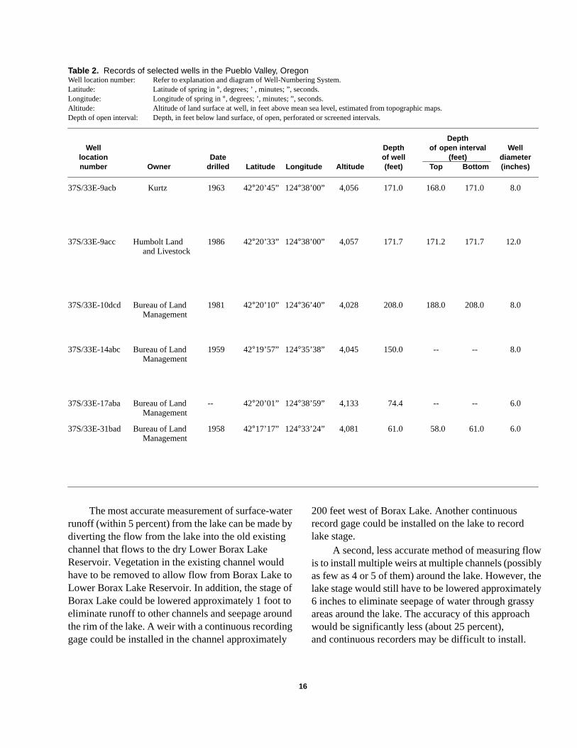
Table 2. Records of selected wells in the Pueblo Valley, OregonWell location number: Refer to explanation and diagram of Well-Numbering System.Latitude: Latitude of spring in°, degrees; ’ , minutes; ”, seconds.Longitude: Longitude of spring in°, degrees; ’, minutes; ”, seconds.Altitude: Altitude of land surface at well, in feet above mean sea level, estimated from topographic maps.Depth of open interval: Depth, in feet below land surface, of open, perforated or screened intervals.
DepthWell Depth of open interval Well
location Date of well (feet) diameternumber Owner drilled Latitude Longitude Altitude (feet) Top Bottom (inches)
37S/33E-9acb Kurtz 1963 42°20’45” 124°38’00” 4,056 171.0 168.0 171.0 8.0
37S/33E-9acc Humbolt Land 1986 42°20’33” 124°38’00” 4,057 171.7 171.2 171.7 12.0and Livestock
37S/33E-10dcd Bureau of Land 1981 42°20’10” 124°36’40” 4,028 208.0 188.0 208.0 8.0Management
37S/33E-14abc Bureau of Land 1959 42°19’57” 124°35’38” 4,045 150.0 -- -- 8.0Management
37S/33E-17aba Bureau of Land -- 42°20’01” 124°38’59” 4,133 74.4 -- -- 6.0Management
37S/33E-31bad Bureau of Land 1958 42°17’17” 124°33’24” 4,081 61.0 58.0 61.0 6.0Management
w
elyy
The most accurate measurement of surface-warunoff (within 5 percent) from the lake can be made bdiverting the flow from the lake into the old existingchannel that flows to the dry Lower Borax LakeReservoir. Vegetation in the existing channel wouldhave to be removed to allow flow from Borax Lake toLower Borax Lake Reservoir. In addition, the stage oBorax Lake could be lowered approximately 1 foot teliminate runoff to other channels and seepage arouthe rim of the lake. A weir with a continuous recordinggage could be installed in the channel approximatel
8/30/00–12:59:48 16
tery
fond
y
200 feet west of Borax Lake. Another continuousrecord gage could be installed on the lake to recordlake stage.
A second, less accurate method of measuring flois to install multiple weirs at multiple channels (possiblyas few as 4 or 5 of them) around the lake. However, thlake stage would still have to be lowered approximate6 inches to eliminate seepage of water through grassareas around the lake. The accuracy of this approachwould be significantly less (about 25 percent),and continuous recorders may be difficult to install.
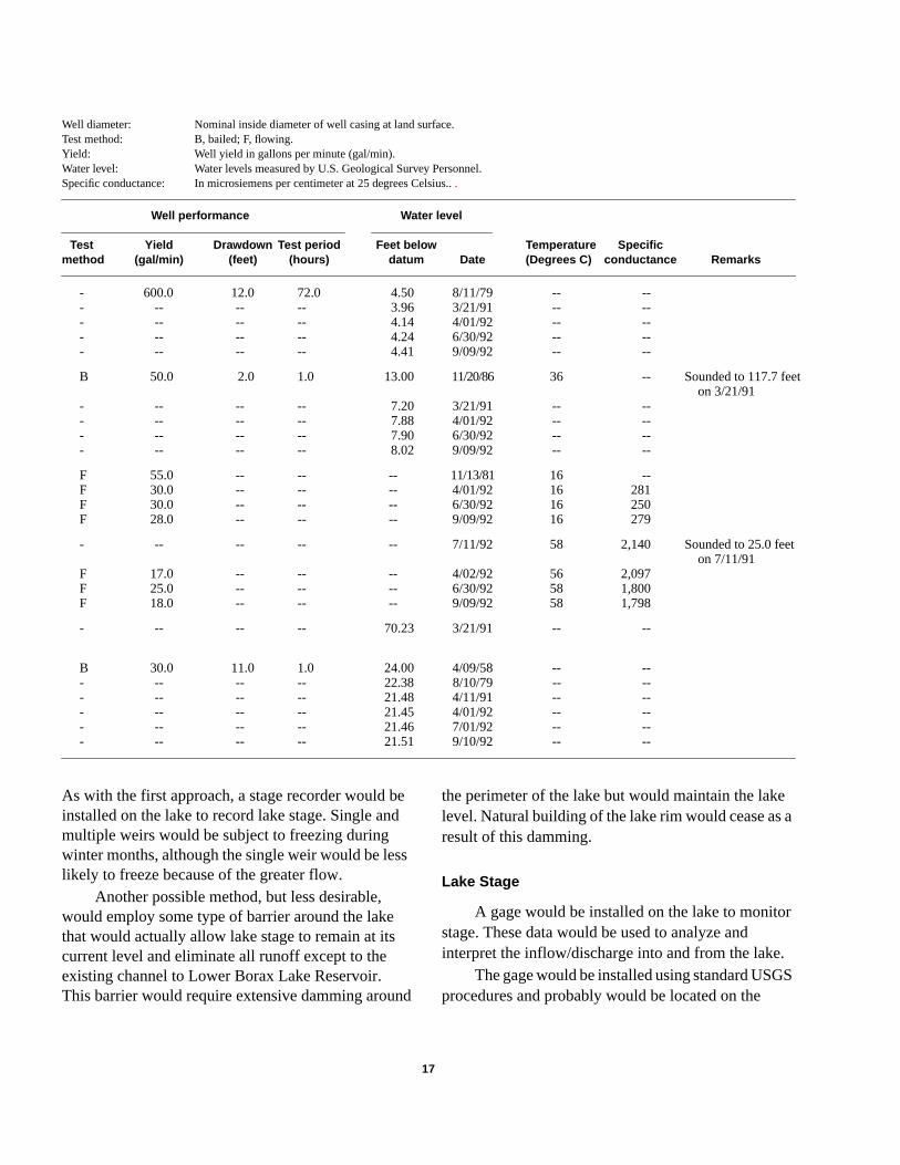
Well diameter: Nominal inside diameter of well casing at land surface.Test method: B, bailed; F, flowing.Yield: Well yield in gallons per minute (gal/min).Water level: Water levels measured by U.S. Geological Survey Personnel.Specific conductance: In microsiemens per centimeter at 25 degrees Celsius...
Well performance Water level
Test Yield Drawdown Test period Feet below Temperature Specificmethod (gal/min) (feet) (hours) datum Date (Degrees C) conductance Remarks
- 600.0 12.0 72.0 4.50 8/11/79 -- --- -- -- -- 3.96 3/21/91 -- --- -- -- -- 4.14 4/01/92 -- --- -- -- -- 4.24 6/30/92 -- --- -- -- -- 4.41 9/09/92 -- --
B 50.0 2.0 1.0 13.00 11/20/86 36 -- Sounded to 117.7 feeton 3/21/91
- -- -- -- 7.20 3/21/91 -- --- -- -- -- 7.88 4/01/92 -- --- -- -- -- 7.90 6/30/92 -- --- -- -- -- 8.02 9/09/92 -- --
F 55.0 -- -- -- 11/13/81 16 --F 30.0 -- -- -- 4/01/92 16 281F 30.0 -- -- -- 6/30/92 16 250F 28.0 -- -- -- 9/09/92 16 279
- -- -- -- -- 7/11/92 58 2,140 Sounded to 25.0 feeton 7/11/91
F 17.0 -- -- -- 4/02/92 56 2,097F 25.0 -- -- -- 6/30/92 58 1,800F 18.0 -- -- -- 9/09/92 58 1,798
- -- -- -- 70.23 3/21/91 -- --
B 30.0 11.0 1.0 24.00 4/09/58 -- --- -- -- -- 22.38 8/10/79 -- --- -- -- -- 21.48 4/11/91 -- --- -- -- -- 21.45 4/01/92 -- --- -- -- -- 21.46 7/01/92 -- --- -- -- -- 21.51 9/10/92 -- --
a
r
.S
As with the first approach, a stage recorder would beinstalled on the lake to record lake stage. Single andmultiple weirs would be subject to freezing duringwinter months, although the single weir would be lesslikely to freeze because of the greater flow.
Another possible method, but less desirable,would employ some type of barrier around the lakethat would actually allow lake stage to remain at itscurrent level and eliminate all runoff except to theexisting channel to Lower Borax Lake Reservoir.This barrier would require extensive damming around
the perimeter of the lake but would maintain the lakelevel. Natural building of the lake rim would cease asresult of this damming.
Lake Stage
A gage would be installed on the lake to monitostage. These data would be used to analyze andinterpret the inflow/discharge into and from the lake
The gage would be installed using standard USGprocedures and probably would be located on the
8/30/00–12:59:48 17
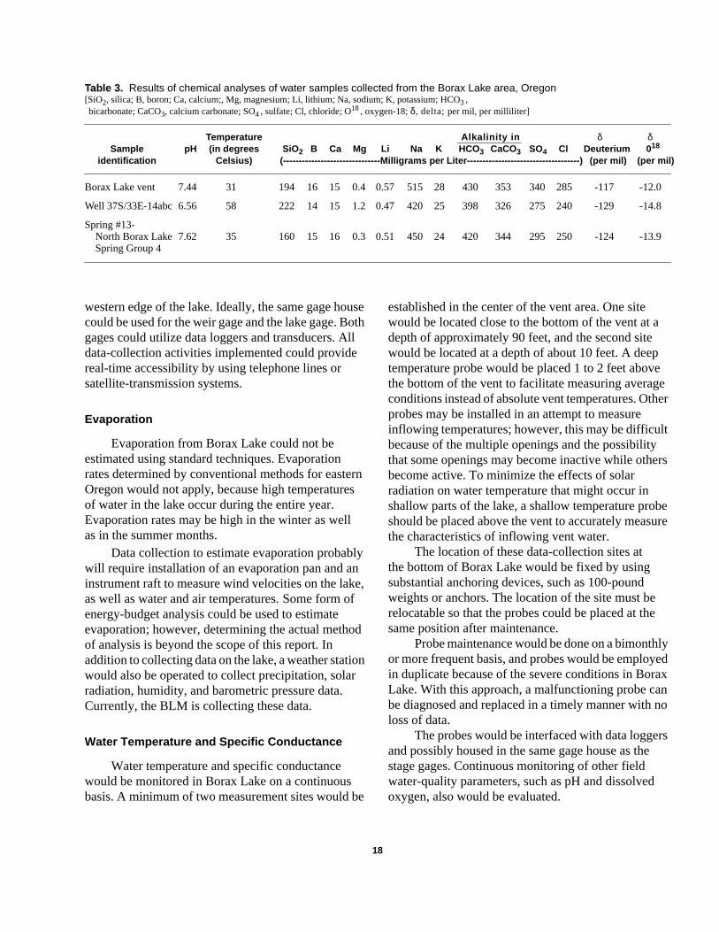
Table 3. Results of chemical analyses of water samples collected from the Borax Lake area, Oregon[SiO2, silica; B, boron; Ca, calcium;, Mg, magnesium; Li, lithium; Na, sodium; K, potassium; HCO3,bicarbonate; CaCO3, calcium carbonate; SO4, sulfate; Cl, chloride; O18, oxygen-18;δ, delta;per mil, per milliliter]
Temperature Alkalinity in δ δSample pH (in degrees SiO 2 B Ca Mg Li Na K HCO 3 CaCO3 SO4 Cl Deuterium 0 18
identification Celsius) (-------------------------------Milligrams per Liter------------------------------------) (per mil) (per mil )
Borax Lake vent 7.44 31 194 16 15 0.4 0.57 515 28 430 353 340 285 -117 -12.0
Well 37S/33E-14abc 6.56 58 222 14 15 1.2 0.47 420 25 398 326 275 240 -129 -14.8
Spring #13-North Borax Lake 7.62 35 160 15 16 0.3 0.51 450 24 420 344 295 250 -124 -13.9Spring Group 4
eeer
t
rs
eure
e
lyedx
no
s
western edge of the lake. Ideally, the same gage housecould be used for the weir gage and the lake gage. Bothgages could utilize data loggers and transducers. Alldata-collection activities implemented could providereal-time accessibility by using telephone lines orsatellite-transmission systems.
Evaporation
Evaporation from Borax Lake could not beestimated using standard techniques. Evaporationrates determined by conventional methods for easternOregon would not apply, because high temperaturesof water in the lake occur during the entire year.Evaporation rates may be high in the winter as wellas in the summer months.
Data collection to estimate evaporation probablywill require installation of an evaporation pan and aninstrument raft to measure wind velocities on the lake,as well as water and air temperatures. Some form ofenergy-budget analysis could be used to estimateevaporation; however, determining the actual methodof analysis is beyond the scope of this report. Inaddition to collecting data on the lake, a weather stationwould also be operated to collect precipitation, solarradiation, humidity, and barometric pressure data.Currently, the BLM is collecting these data.
Water Temperature and Specific Conductance
Water temperature and specific conductancewould be monitored in Borax Lake on a continuousbasis. A minimum of two measurement sites would be
established in the center of the vent area. One sitewould be located close to the bottom of the vent at adepth of approximately 90 feet, and the second sitewould be located at a depth of about 10 feet. A deeptemperature probe would be placed 1 to 2 feet abovthe bottom of the vent to facilitate measuring averagconditions instead of absolute vent temperatures. Othprobes may be installed in an attempt to measureinflowing temperatures; however, this may be difficulbecause of the multiple openings and the possibilitythat some openings may become inactive while othebecome active. To minimize the effects of solarradiation on water temperature that might occur inshallow parts of the lake, a shallow temperature probshould be placed above the vent to accurately measthe characteristics of inflowing vent water.
The location of these data-collection sites atthe bottom of Borax Lake would be fixed by usingsubstantial anchoring devices, such as 100-poundweights or anchors. The location of the site must berelocatable so that the probes could be placed at thsame position after maintenance.
Probe maintenance would be done on a bimonthor more frequent basis, and probes would be employin duplicate because of the severe conditions in BoraLake. With this approach, a malfunctioning probe cabe diagnosed and replaced in a timely manner with nloss of data.
The probes would be interfaced with data loggerand possibly housed in the same gage house as thestage gages. Continuous monitoring of other fieldwater-quality parameters, such as pH and dissolvedoxygen, also would be evaluated.
8/30/00–12:59:48 18
d
e
ehld
er
eosis
eata
Water-Quality Sampling and Analysis
Geothermal development or production ofgeothermal fluids could affect discharge from thegeothermal system as well as the chemical compositiof the discharging water. The following discussiondescribes a plan for collecting water samples in theBorax Lake area for chemical analysis.
Water-quality samples would be collectedfrom Borax Lake using standard USGS procedures.Conditions in the lake may require that samplingmethods be devised to ensure that samples are alwcollected from the same location for comparisonpurposes, although samples would be taken at variodepths. Chemical constituents proposed for analyseare listed in the Appendix.
Physical parameters and chemical constituentswere selected on the basis of “Guidelines for acquirinenvironmental baseline data on Federal geothermalleases,” (U.S. Department of Interior, 1977). Oxygenand deuterium isotope concentrations were includedbecause of their usefulness in identifying sources ofwater.
The schedule for sampling the Borax Lake studarea would be designed to evaluate variability inconstituents over periods of days, weeks, and yearsAlso, samples would be collected at various depths.A suggested schedule for sampling is as follows.Suggested sampling schedule for Borax Lake areamonitoring:
Number Estimatedof samples number of
per site sample setsDate Lake(4)* Springs(2)* Wells(2)* per trip
October 3 3 3 24November 1 1 1 8December 1 1 1 8January 1 1 1 8February 1 1 1 8March 1 1 1 8AprilMayJune 1 1 1 8JulyAugustSeptember 1 1 1 8
* The number in parentheses indicates the number of sampling sites.
8/30/00–12:59:48 19
on
ays
uss
g
y
.
October sampling would be for field parameters anmajor chemical constituents, with the exception ofone sample set for each site that would include allchemical constituents described in the Appendix.
After monitoring for 1 to 2 years with thetype of sampling schedule suggested, variations inparameters could be evaluated and the samplingschedule modified as needed. If the variance of thedata for selected parameters is small, the samplingfrequency and monitoring costs could be reduced.
Shallow Ground WaterAdjacent to Borax Lake
Ground-Water Levels
Surface-water discharge from the lake would bmonitored to detect any significant changes in inflowto Borax Lake. The ability to use discharge as anindicator of inflow depends on other components ofthe water budget for the lake. One component is thshallow ground-water discharge from the lake, whicshould remain constant if the stage of the lake is herelatively constant.
Shallow ground-water levels near Borax Lakecould be monitored using shallow drive-pointpiezometers. These piezometers would be used tomeasure shallow water levels and to evaluate whethor not the shallow ground-water system is inequilibrium.
Piezometers would be placed along flow lines,and at least two sets of three piezometers wouldbe installed in a radial pattern out from the lake.Each monitoring set would have a piezometer atapproximately 10-, 20-, and 30-foot distances fromthe lake. Water-level measurements would be madon a monthly basis in these piezometers; one or twpiezometers would be monitored on a continuous baby using transducers and data loggers.
This water-level data would be useful todetermine if the shallow ground-water system is inequilibrium and also to determine gradients near thlake. The gradient data and some simple slug-test dfor calculation of hydraulic conductivity could allowan approximate estimation of shallow ground waterdischarged from the lake.
e
l
n
teme
r
)x
,
,
.
North Borax Lake Spring Group 1
Water Temperature and Specific Conductance
Water temperature and specific conductancewould be monitored in at least one hot spring andpossibly two hot springs in the closest group of springlocated north of the lake. These springs may also beimportant indicator of variations in temperatures andchemistry in the local geothermal system. Measuremeof discharge at one of the springs is another possibilit
Monitoring in the springs would be done by usingan approach similar to that used in Borax Lake. Dataloggers could be housed in a gage house at the sprinand the resulting data also would be available on a retime basis.
Water-Quality Sampling and Analysis
Springs would be sampled according to thesuggested schedule given in the “Borax Lake, WaterQuality Sampling and Analysis” section of this reportThe samples would be analyzed for the constituentslisted in the Appendix. The only exception would bethe October samples, for which only one set of samplwould be analyzed for the complete set of chemicalconstituents. All other samples collected during theOctober sampling would be analyzed for majorchemical constituents only.
Wells
Construction
Well 37S/33E-14abc is located approximatelyone-half mile northeast of Borax Lake. The well wasapparently drilled as part of a sodium-prospectingproject during the late 1950’s and early 1960’s. The weflows at a rate of approximately 50 gallons per minutand water temperature has been measured at 58°C.The depth of the well was sounded at 25 feet; howevethere is some question about the construction of thewell. This well may provide a good site for collectionof baseline information, but it must be reconditioned sthat the open interval of the well can be verified. Thewellhead would also require modification to allow thewell to be shut in for measurement of static water level
8/30/00–12:59:48 20
san
nty.
gs,al-
-.
es
lle
r,
o
s;
however, accurate flow measurements also could bmade.
Verification of construction and modification ofthe wellhead would require the hiring of contractors.Drilling, down-hole camera, and geophysicalequipment may be needed to prepare the well formonitoring. In the event that the well cannot beproperly reconditioned for monitoring, the well couldbe sealed and abandoned to prevent human-causeddischarge of geothermal water.
Well 37S/33E-10dcd is approximately 1 milenorthwest of Borax Lake and also would be a usefusite for data collection.
Water Levels, Temperature, and Discharge
If wells 37S/33E-14abc and 37S/33E-10dcd cabe shut in, water levels and temperatures would bemonitored on a continuous basis. In addition, accuradischarge measurements would be made with the safrequency as water-quality sampling. If for somereason it is not possible to shut the wells in, onlydischarge and temperature would be measured.Specific conductance also may be monitored on acontinuous basis as an indicator of changes in watechemistry with time.
Water-Quality Sampling and Analysis
The wells (37S/33E-14abc and 37S/33E-10dcdwould be sampled by using the schedule in the “BoraLake, Water-Quality Sampling and Analysis” sectionof this report. Both wells are flowing wells; thereforepumps would not be needed. The wells would beallowed to flow until three well-bore volumes of waterhave been removed from the well to assure thatformation water is being sampled.
Deep Geothermal Well(s)
Review Available Geothermal Well,Geologic Map, and Geophysical Data
As part of Phase II of the Borax Lake area studycollection of hydrologic data from wells locatedbetween the proposed geothermal development andenvironmentally sensitive areas would be necessary
,
,
t
g
These wells could provide an “early warning” data-collection network, so that appropriate actions couldbe taken before geothermal development activitieswould affect sensitive areas. A review of availabledata from existing and abandoned geothermal wells,geologic maps, and geophysical information is neededto determine if existing wells are adequate forcollection of data or if new wells should be drilled formonitoring. This review was suggested in the Phase IIwork plan. If geothermal development in the BoraxLake area occurs, the use of monitoring wells shouldbe evaluated at that time.
There are several observation and explorationwells just south of Borax Lake that, if still accessibleand completed in appropriate zones, could be used formonitoring purposes.
Geologic and geophysical data are available forthe Pueblo Valley near Borax Lake. Much of these dataare, however, proprietary to companies that collectedthe information. This information and possiblyadditional information may have to be reviewed todetermine the feasibility of using existing or newwells to monitor ground-water conditions betweenBorax Lake and areas of geothermal development.This review would require cooperation betweenFederal agencies and private-exploration companies.
When the existing data are reviewed, it maybecome apparent that the system is too complex tolocate monitoring wells properly, or that drilling deepwells near Borax Lake could adversely affect thegeothermal system. It may also be determined thatthe most appropriate way to monitor the thermalaquifer or upflow system to Borax Lake is to install ashallow well near North Borax Lake Spring Group 1to evaluate changes in thermal-aquifer pressures.
SELECTED REFERENCES
Garber, M.S., and Koopman, F.C., 1968, Methodsof measuring water levels in deep wells:U.S. Geological Survey Techniques of Water-Resources Investigations, book 8, chap. A1, 23 p.
Gonthier, J.B., 1985, A description of aquifer units ineastern Oregon: U.S. Geological Survey Water-Resources Investigations Report 84–4095, 39 p.,4 sheets.
Reed, J.E., Bedinger, M.S., and Gonthier, J.B., 1984,Maps showing ground-water units and number oflarge capacity wells, Basin and Range Province,Oregon: U.S. Geological Survey Water-ResourcesInvestigations Report 83–4120–A, 4 p., 1 sheet,scale 1:500,000.
Reed, J.E., Bedinger, M.S., Gonthier, J.B., Langer, W.H.McFarland, W.D., and Mulvihill, D.A., 1984, Mapsshowing ground-water levels, springs, and depth toground water, Basin and Range Province, Oregon:U.S. Geological Survey Water-ResourcesInvestigations Report 83–4120–B, 5 p., 1 sheet,scale 1:500,000.
Sifford, Alex, Beale, Kasi, 1991, Economic impacts ofgeothermal development in Harney County, Oregonprepared for the Bonneville Power Administration bythe Oregon Department of Energy under agreemenno. DE–BI79–90BP07129: Salem, Oregon, 31 p.
Thompson, T.H., Chappel, Richard, Gonthier, J.B., andMcFarland, W.D., 1984, Maps showing distributionof dissolved solids and dominant chemical type inground water, Basin and Range Province, Oregon:U.S. Geological Survey Water-ResourcesInvestigation Report 83–4120–C, 5 p., 1 sheet,scale 1:500,000.
Townley, P.J., Soja, C.M., Sidle, W.C., 1980, Ground-water data for Riley and Andrews Resource Areas,Southeastern Oregon: U.S. Geological SurveyOpen-File Report 80–419, 32 p.
U.S. Department of Interior, 1977, Guidelines for acquirinenvironmental baseline data on Federal geothermalleases: Menlo Park, California, GeothermalEnvironmental Advisory Panel, 26 p.
8/30/00–12:59:48 21

8/30/00–12:59:48 22
APPENDIX
8/30/00–12:59:48 23
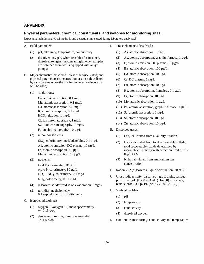
APPENDIX
Physical parameters, chemical constituents, and isotopes for monitoring sites.[Appendix includes analytical methods and detection limits used during laboratory analyses.]
A. Field parameters D. Trace elements (dissolved):
(1) pH, alkalinity, temperature, conductivity
(2) dissolved oxygen, when feasible (for instance,dissolved oxygen is not meaningful when samplesare obtained from wells equipped with air-jetpumps)
B. Major chemistry (dissolved unless otherwise stated) andphysical parameters (concentration or unit values listedby each parameter are the minimum detection levels thatwill be used)
(1) major ions:
Ca, atomic absorption, 0.1 mg/LMg, atomic absorption, 0.1 mg/LNa, atomic absorption, 0.1 mg/LK, atomic absorption, 0.1 mg/LHCO3, titration, 1 mg/L
Cl, ion chromatography, 1 mg/LSO4, ion chromatography, 1 mg/L
F, ion chromatography, 10µg/L
(2) minor constituents:
SiO2, colorimetry, molybdate blue, 0.1 mg/L
A1, atomic emission, DG plasma, 10µg/LFe, atomic absorption, 10µg/LMn, atomic absorption, 10µg/L
(3) nutrients:
total P, colorimetry, 10µg/Lortho P, colorimetry, 10µg/LNO2 + NO3, colorimetry, 0.1 mg/L
NH4, colorimetry, 0.01 mg/L
(4) dissolved solids:residue on evaporation,1 mg/L
(5) turbidity: nephelometry,0.1 nephelometric turbidity units
C. Isotopes (dissolved):
(1) oxygen-18/oxygen-16, mass spectrometry,+/- 0.15 o/oo
(2) deuterium/protium, mass spectrometry,+/- 1.5 o/oo
(1) As, atomic absorption, 1µg/L
(2) Ag, atomic absorption, graphite furnace, 1µg/L
(3) B, atomic emission, DC plasma, 10µg/L
(4) Ba, atomic absorption, 100µg/L
(5) Cd, atomic absorption, 10µg/L
(6) Cr, DC plasma, 1µg/L
(7) Cu, atomic absorption, 10µg/L
(8) Hg, atomic absorption, flameless, 0.1µg/L
(9) Li, atomic absorption, 10µg/L
(10) Mo, atomic absorption, 1µg/L
(11) Pb, atomic absorption, graphite furnace, 1µg/L
(12) Se, atomic absorption, 1µg/L
(13) Sr, atomic absorption, 10µg/L
(14) Zn, atomic absorption, 10µg/L
E. Dissolved gases
(1) CO2, calibrated from alkalinity titration
(2) H2S, calculated from total recoverable sulfide;total recoverable sulfide determined byiodometric titrimetry with detection limit of 0.5mg/L as S
(3) NH3, calculated from ammonium ionconcentration
F. Radon-222 (dissolved): liquid scintillation, 70 pCi/L
G. Gross radioactivity (dissolved): gross alpha, residueproc., 0.4µg/L (U), 0.4 pCi/L (Th-230) gross beta,residue proc., 0.4 pCi/L (Sr-90/Y-90, Cs-137)
H. Vertical profiles:
(1) pH
(2) temperature
(3) conductivity
(4) dissolved oxygen
I. Continuous monitoring: conductivity and temperature
8/30/00–12:59:48 24