Embed Size (px)
Citation preview
IBIS RJ.03 Project for Sale Asking € 4,700.00 (no VAT, TVA, MwSt) The information in this file is believed to be
correct at the time of writing. Even so, I
cannot guarantee that there will be no errors
or omissions. For this reason I highly
encourage you to inspect this project;
specifications subject to prior verification by
purchaser
I WANT TO FREE UP MY WORKSHOP
Substantially below replacement cost for just the material you’ll hit
the ground running with this almost complete airframe ‘kit’!
• Add foam for the wing, a VW-derived engine and instruments
and you’ll have most if not all bases covered.
• Taking over this RJ.03 IBIS project will reduce your build time by
at least 2 – 4 years.
• Price does not include shipment, crating, etc.
• No partial kit sale; the value of this project is in the
completeness of the airframe materials provided, the
templates & jig provided and the assembly work done so
far. It would be a shame to tear that apart.
• Transporting this project is your responsibility
Fuselage
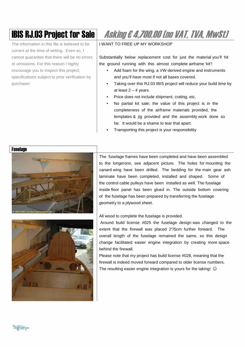
The fuselage frames have been completed and have been assembled
to the longerons, see adjacent picture. The holes for mounting the
canard wing have been drilled. The bedding for the main gear ash
laminate have been completed, installed and shaped. Some of
the control cable pulleys have been installed as well. The fuselage
inside floor panel has been glued in. The outside bottom covering
of the fuselage has been prepared by transferring the fuselage
geometry to a plywood sheet.
All wood to complete the fuselage is provided.
Around build license #025 the fuselage design was changed to the
extent that the firewall was placed 2”/5cm further forward. The
overall length of the fuselage remained the same, so this design
change facilitated easier engine integration by creating more space
behind the firewall.
Please note that my project has build license #028, meaning that the
firewall is indeed moved forward compared to older license numbers.
The resulting easier engine integration is yours for the taking! ☺
Canopy
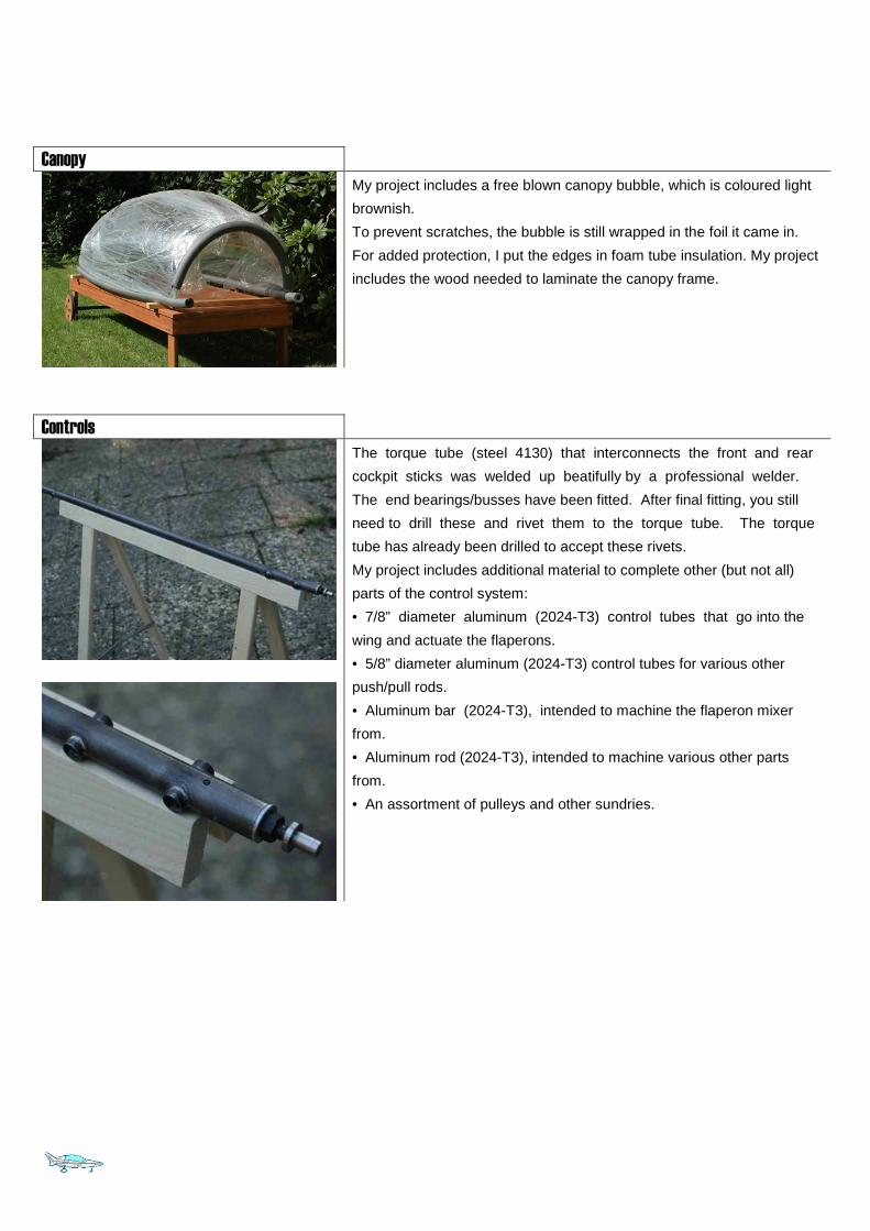
My project includes a free blown canopy bubble, which is coloured light
brownish.
To prevent scratches, the bubble is still wrapped in the foil it came in.
For added protection, I put the edges in foam tube insulation. My project
includes the wood needed to laminate the canopy frame.
Controls
The torque tube (steel 4130) that interconnects the front and rear
cockpit sticks was welded up beatifully by a professional welder.
The end bearings/busses have been fitted. After final fitting, you still
need to drill these and rivet them to the torque tube. The torque
tube has already been drilled to accept these rivets.
My project includes additional material to complete other (but not all)
parts of the control system:
• 7/8” diameter aluminum (2024-T3) control tubes that go into the
wing and actuate the flaperons.
• 5/8” diameter aluminum (2024-T3) control tubes for various other
push/pull rods.
• Aluminum bar (2024-T3), intended to machine the flaperon mixer
from.
• Aluminum rod (2024-T3), intended to machine various other parts
from.
• An assortment of pulleys and other sundries.
Canard wing
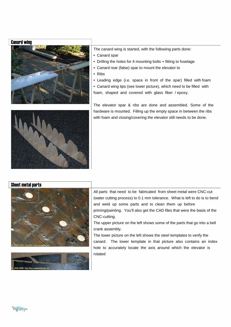
The canard wing is started, with the following parts done:
• Canard spar
• Drilling the holes for 4 mounting bolts + fitting to fuselage
• Canard rear (false) spar to mount the elevator to
• Ribs
• Leading edge (i.e. space in front of the spar) filled with foam
• Canard wing tips (see lower picture), which need to be filled with
foam, shaped and covered with glass fiber / epoxy.
The elevator spar & ribs are done and assembled. Some of the
hardware is mounted. Filling up the empty space in between the ribs
with foam and closing/covering the elevator still needs to be done.
Sheet metal parts
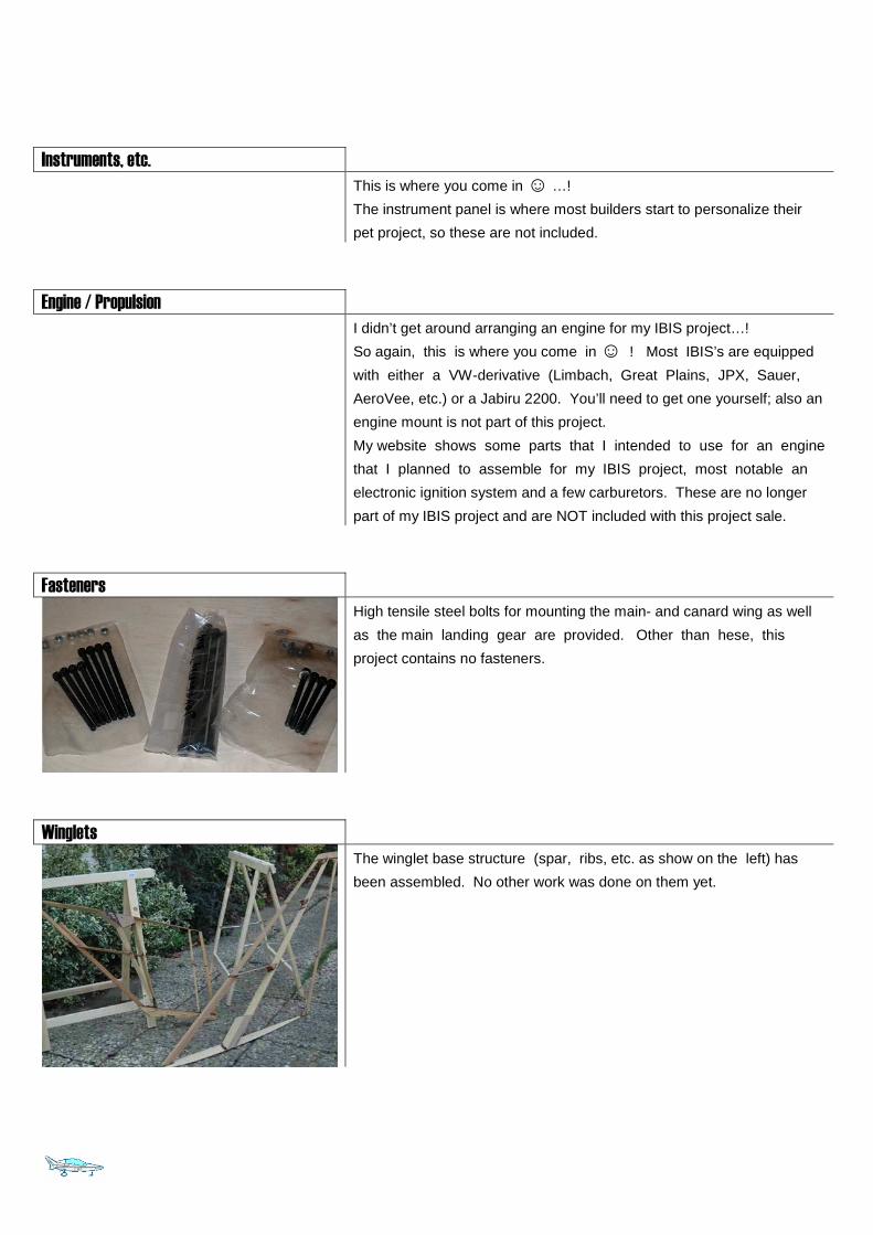
All parts that need to be fabricated from sheet metal were CNC-cut
(water cutting process) to 0.1 mm tolerance. What is left to do is to bend
and weld up some parts and to clean them up before
priming/painting. You’ll also get the CAD files that were the basis of the
CNC-cutting.
The upper picture on the left shows some of the parts that go into a bell
crank assembly.
The lower picture on the left shows the steel templates to verify the
canard. The lower template in that picture also contains an index
hole to accurately locate the axis around which the elevator is
rotated
Instruments, etc.
This is where you come in ☺ …!
The instrument panel is where most builders start to personalize their
pet project, so these are not included.
Engine / Propulsion
I didn’t get around arranging an engine for my IBIS project…!
So again, this is where you come in ☺ ! Most IBIS’s are equipped
with either a VW-derivative (Limbach, Great Plains, JPX, Sauer,
AeroVee, etc.) or a Jabiru 2200. You’ll need to get one yourself; also an
engine mount is not part of this project.
My website shows some parts that I intended to use for an engine
that I planned to assemble for my IBIS project, most notable an
electronic ignition system and a few carburetors. These are no longer
part of my IBIS project and are NOT included with this project sale.
Fasteners
High tensile steel bolts for mounting the main- and canard wing as well
as the main landing gear are provided. Other than hese, this
project contains no fasteners.
Winglets
The winglet base structure (spar, ribs, etc. as show on the left) has
been assembled. No other work was done on them yet.
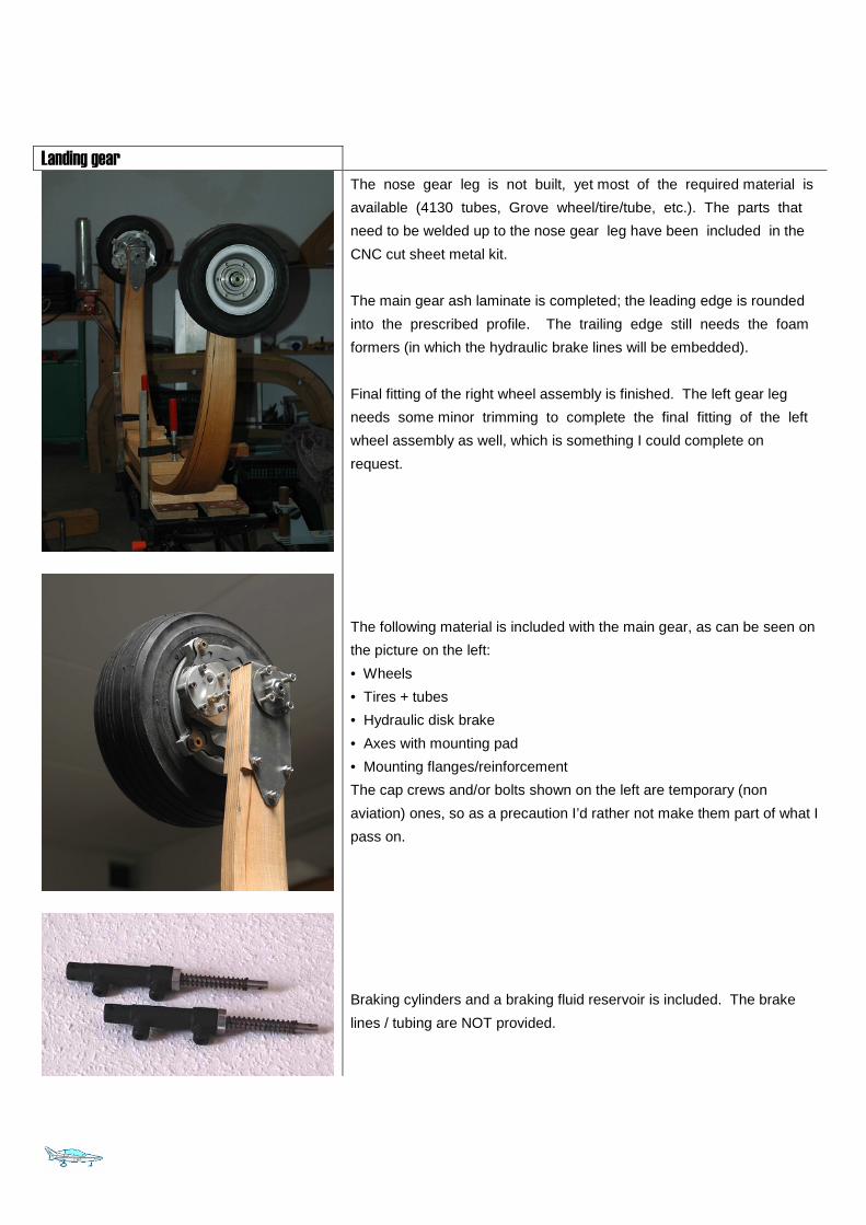
Landing gear
The nose gear leg is not built, yet most of the required material is
available (4130 tubes, Grove wheel/tire/tube, etc.). The parts that
need to be welded up to the nose gear leg have been included in the
CNC cut sheet metal kit.
The main gear ash laminate is completed; the leading edge is rounded
into the prescribed profile. The trailing edge still needs the foam
formers (in which the hydraulic brake lines will be embedded).
Final fitting of the right wheel assembly is finished. The left gear leg
needs some minor trimming to complete the final fitting of the left
wheel assembly as well, which is something I could complete on
request.
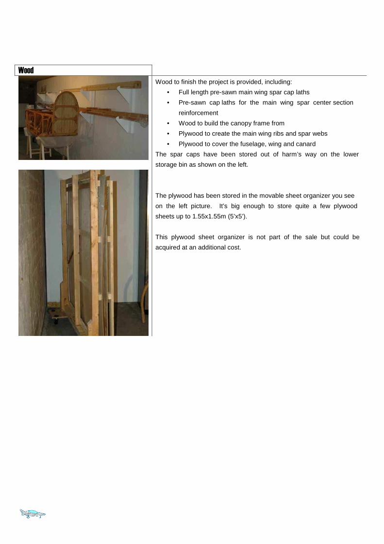
The following material is included with the main gear, as can be seen on
the picture on the left:
• Wheels
• Tires + tubes
• Hydraulic disk brake
• Axes with mounting pad
• Mounting flanges/reinforcement
The cap crews and/or bolts shown on the left are temporary (non
aviation) ones, so as a precaution I’d rather not make them part of what I
pass on.
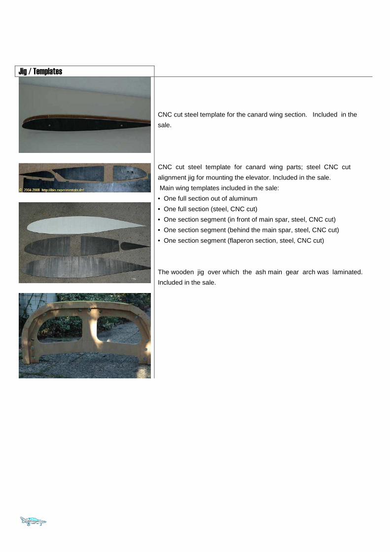
Braking cylinders and a braking fluid reservoir is included. The brake
lines / tubing are NOT provided.
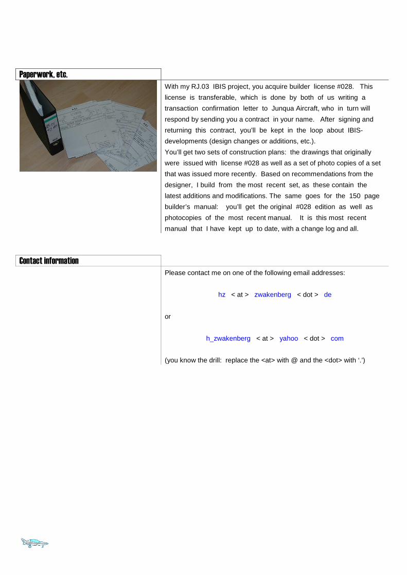
Wood
Wood to finish the project is provided, including:
• Full length pre-sawn main wing spar cap laths
• Pre-sawn cap laths for the main wing spar center section
reinforcement
• Wood to build the canopy frame from
• Plywood to create the main wing ribs and spar webs
• Plywood to cover the fuselage, wing and canard
The spar caps have been stored out of harm’s way on the lower
storage bin as shown on the left.
The plywood has been stored in the movable sheet organizer you see
on the left picture. It’s big enough to store quite a few plywood
sheets up to 1.55x1.55m (5’x5’).
This plywood sheet organizer is not part of the sale but could be
acquired at an additional cost.
Jig / Templates
CNC cut steel template for the canard wing section. Included in the
sale.
CNC cut steel template for canard wing parts; steel CNC cut
alignment jig for mounting the elevator. Included in the sale.
Main wing templates included in the sale:
• One full section out of aluminum
• One full section (steel, CNC cut)
• One section segment (in front of main spar, steel, CNC cut)
• One section segment (behind the main spar, steel, CNC cut)
• One section segment (flaperon section, steel, CNC cut)
The wooden jig over which the ash main gear arch was laminated.
Included in the sale.
Paperwork, etc.
With my RJ.03 IBIS project, you acquire builder license #028. This
license is transferable, which is done by both of us writing a
transaction confirmation letter to Junqua Aircraft, who in turn will
respond by sending you a contract in your name. After signing and
returning this contract, you’ll be kept in the loop about IBIS-
developments (design changes or additions, etc.).
You’ll get two sets of construction plans: the drawings that originally
were issued with license #028 as well as a set of photo copies of a set
that was issued more recently. Based on recommendations from the
designer, I build from the most recent set, as these contain the
latest additions and modifications. The same goes for the 150 page
builder’s manual: you’ll get the original #028 edition as well as
photocopies of the most recent manual. It is this most recent
manual that I have kept up to date, with a change log and all.
Contact information
Please contact me on one of the following email addresses:
hz < at > zwakenberg < dot > de
or
h_zwakenberg < at > yahoo < dot > com
(you know the drill: replace the <at> with @ and the <dot> with ‘.’)
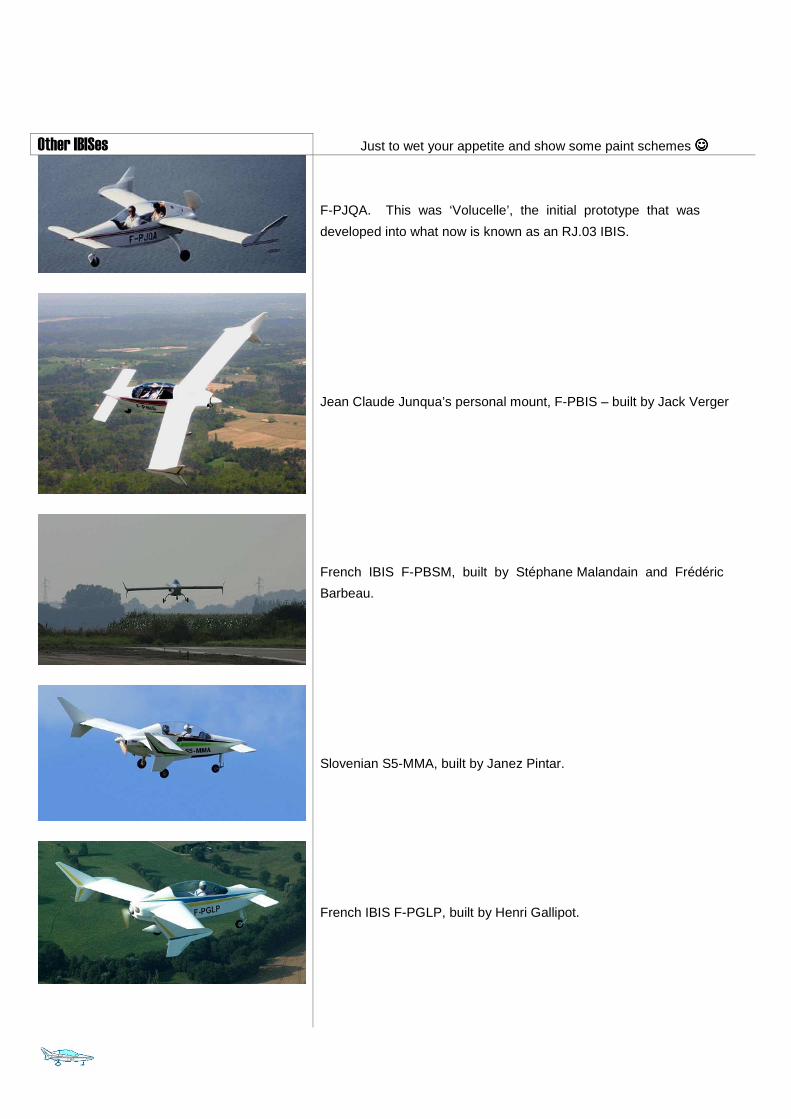
Other IBISes Just to wet your appetite and show some paint schemes ☺☺☺☺
F-PJQA. This was ‘Volucelle’, the initial prototype that was
developed into what now is known as an RJ.03 IBIS.
Jean Claude Junqua’s personal mount, F-PBIS – built by Jack Verger
French IBIS F-PBSM, built by Stéphane Malandain and Frédéric
Barbeau.
Slovenian S5-MMA, built by Janez Pintar.
French IBIS F-PGLP, built by Henri Gallipot.
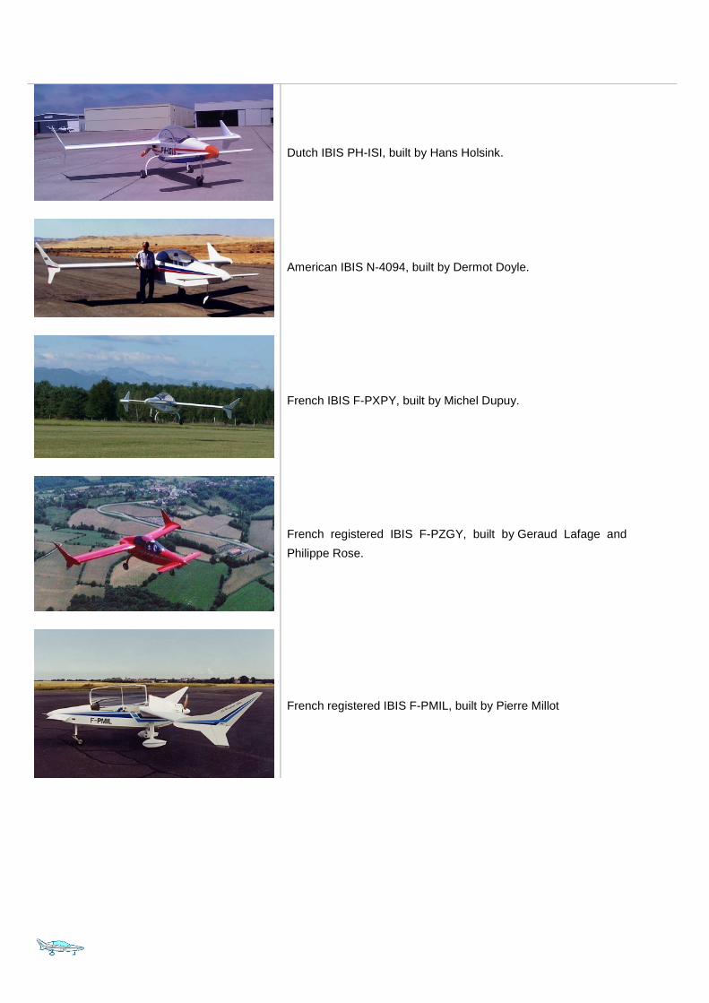
Dutch IBIS PH-ISI, built by Hans Holsink.
American IBIS N-4094, built by Dermot Doyle.
French IBIS F-PXPY, built by Michel Dupuy.
French registered IBIS F-PZGY, built by Geraud Lafage and
Philippe Rose.
French registered IBIS F-PMIL, built by Pierre Millot