Embed Size (px)
Citation preview

HAL Id: hal-02431388https://hal.archives-ouvertes.fr/hal-02431388
Submitted on 7 Jan 2020
HAL is a multi-disciplinary open accessarchive for the deposit and dissemination of sci-entific research documents, whether they are pub-lished or not. The documents may come fromteaching and research institutions in France orabroad, or from public or private research centers.
L’archive ouverte pluridisciplinaire HAL, estdestinée au dépôt et à la diffusion de documentsscientifiques de niveau recherche, publiés ou non,émanant des établissements d’enseignement et derecherche français ou étrangers, des laboratoirespublics ou privés.
Identification of the Propeller Coefficients and DynamicParameters of a Hovering Quadrotor from Flight Data
Damien Six, Sébastien Briot, Julian Erskine, Abdelhamid Chriette
To cite this version:Damien Six, Sébastien Briot, Julian Erskine, Abdelhamid Chriette. Identification of the PropellerCoefficients and Dynamic Parameters of a Hovering Quadrotor from Flight Data. IEEE Robotics andAutomation Letters, IEEE 2020, 5 (2), pp.1063-1070. hal-02431388

1
Identification of the Propeller Coefficients andDynamic Parameters of a Hovering Quadrotor from
Flight DataDamien Six1, Sebastien Briot2, Julian Erskine1 and Abdelhamid Chriette1
Abstract—Several methods can be applied to estimate thepropeller thrust and torque coefficients and dynamics parametersof quadrotor UAVs. These parameters are necessary for manycontrollers that have been proposed for these vehicles. However,these methods require the use of specific test benches, which donot well simulate real flight conditions.
In this paper, a new method is introduced which allows theidentification of the propeller coefficients and dynamic param-eters of a quadrotor in a single procedure. It is based on aTotal-Least-Square identification technique, does not require anyspecific test bench and needs only a measurement of the mass ofthe quadrotor and a recording of data from a flight that can beperformed manually by an operator.
Because the symmetries of classic quadrotors limit the per-formance of the algorithm, an extension of the procedure isproposed. Two types of flights are then used: one with the initialquadrotor and a second flight with an additional payload on thevehicle that modifies the mass distribution. This new procedure,which is validated experimentally, increases the performance ofthe identification and allows an estimation of all the relevantdynamic parameters of the quadrotor near hovering conditions.
Index Terms—Aerial Systems: Mechanics and Control, Cali-bration and Identification
I. INTRODUCTION
QUADROTOR UAVs have recently experienced increas-ing interest with advances in modeling, control and path
planning. Many control techniques have been proposed forthese vehicles [1]–[8]. Several of those control laws require aknowledge of the UAV’s dynamics parameters (e.g. mass andinertia parameters) and propeller thrust and torque coefficients,and are sensitive to the accuracy of the parameters. Anaccurate estimation of the parameters increases the precisionand robustness of the controllers and is therefore required.
Several methods can be applied to estimate the parametersof quadrotor-style UAVs:
Manuscript received: September 6, 2019; Revised December 5, 2019;Accepted December 30, 2019.
This paper was recommended for publication by Editor Jonathan Robertsupon evaluation of the Associate Editor and Reviewers’ comments.
This work was supported by the RFI AtlanSTIC2020 project RAPID1D. Six, J. Erskine and A. Chriette are with the Laboratoire des Sciences
du Numerique de Nantes (LS2N), UMR CNRS 6004, at the Ecole Centralede Nantes, 1 Rue de la Noe, 44321, Nantes, France. Damien.Six,Julian.Erskine, [email protected]
2S. Briot is with the LS2N at the Centre National de la RechercheScientifique, 44321, Nantes, France. [email protected]
Digital Object Identifier (DOI): see top of this page
• Estimation of the frame dynamic parameters from design[9], [10]: This method can lead to an unevaluated lack ofprecision in the estimation of the parameters.
• Experimental estimation of the structure parameters:Apart from the mass which is directly measured with ascale, the other parameters require specific test benches.As an example, in [11], the inertia parameters are mea-sured indirectly with a pendulum device. With such meth-ods, the precision of the inertia parameters are impactedby the precision of the other ones previously measured.
• Estimation of the dynamic parameters from the analysisof flight data [12]–[14] by means of a Kalman filterassuming the knowledge of, at least, the propeller co-efficients of thrust and torque.
Those algorithms all require a knowledge of the propellercoefficients. The estimation of those coefficients and themodelling of aerodynamic effects are studied with specific testbenches [15]–[18] and may not be completely equivalent tothose appearing during a free flight of the drone.
For classical robotic manipulators, most of the dynamic off-line identification methods use an Inverse Dynamic Identifica-tion Model (IDIM), that gives a linear relation between thejoint forces/torques and the dynamic parameters, and estimatethe parameter values using least squares techniques (LS) [19]–[21]. This procedure is called the IDIM-LS technique. Anextension of this method using Total Least Square (IDIM-TLS) is also used to identify dynamic parameters and jointdrive gains of robot manipulators in a single procedure [22].
In this research, a new method is proposed to identify all thestructure and rotor parameters for a quadrotor UAV, inspiredby the IDIM-TLS procedure. Our approach aims to obtain anidentification of the dynamic parameters of the device withoutany specific test bench or a computation of some of the param-eters from design, as other methods would generally require. Ituses the command reference of the propeller velocities, and theflight data collected while the robot is operated by a humanpilot. All the dynamic parameters and propeller coefficientsare calculated in one step as the Total Least Square solution(TLS) of an overdetermined system. The method only requiresa knowledge of the vehicle mass, which is easily measuredusing a scale. This algorithm was established in the scope ofa project on aerial manipulation. Thus, the study is limited tonear hovering flight configurations.
The paper is organized as follows. In the next Section,we define the inverse dynamic identification model of thequadrotor. In Section III, the TLS identification procedure is

2
Fig. 1. Local frame and propeller positions P1...P4 of the quadrotor.
introduced. Two different types of data can be collected inorder to feed the identification model: data from the InertialMeasurement Unit (IMU) or from a motion capture system(MOCAP). Identification results by using the first or secondset of data are then compared in the Section IV. Becausea classic quadrotor presents some symmetries that will leadto a failure of the identification of some dynamic parametersusing the TLS method, an extended version of the procedureis introduced in order to overcome this limitation. It is basedon a modification of the mass distribution of the UAV andrecordings of two types of flight data: a first set for the usualquadrotor, and second set with a modified configuration of thequadrotor. Finally, in Section V, conclusions are drawn.
II. DYNAMIC MODEL OF A QUADROTOR
The quadrotor vehicle consists of four individual rotorsattached to a rigid cross airframe (Fig. 1). The control ofa quadrotor is achieved by differential control of the thrustand drag torques generated by each rotor. The system isunderactuated, with only four inputs available to control thesix Degrees of Freedom (DoF). The dynamics of the quadrotorare described through a combination of the rigid body dynamicequations (Section II-A) and the model of the propellers(Section II-B).
A. Rigid body dynamics
Let us consider a mobile frame Fd(Od,xd,yd, zd) attachedto the quadrotor (Fig. 1). The origin of this frame Od isat the middle of the cross. The xd axis is placed along theaxis of one of the arms and the zd axis is aligned with thequadrotor propellers axes. A standard assumption in quadrotormodelling and control is to consider this origin as the Centerof Mass (CoM) of the vehicle. However, this assumptionis not guaranteed in general. We aim to identify the realposition of the CoM with the identification procedure. Forthis purpose, a general model of the rigid body dynamics isused. In this model, mechanical effects affecting the main bodyof the quadrotor are described. This study however neglectsaerodynamical forces acting on the quadrotor frame. Thoseforces become non negligible at high speed (over 5 m/s) [23]but those flight configurations are out of the scope of thisstudy. The ten dynamic parameters of a rigid body are thefollowings:
• The mass m
• The 3 components msx, msy , msz of the first momentof inertia ms in the local frame, at its origin Od,
• The 6 components of the symmetric inertia matrix in thelocal frame, at its origin Od,
I =
Ixx Ixy IxzIxy Iyy IyzIxz Iyz Izz
The mass is the only parameter that is easily measured. Allthe others unknown parameters are regrouped in a vector χ:
χT = [msx,msy,msz, Ixx, Iyy, Izz, Ixy, Ixz, Iyz]
The following notations are also defined• g = [0, 0,−g]T , g > 0, is the gravity vector, defined in
the world frame.• ζ is the position of the mobile frame origin Od.• ad = [ax, ay, az]
T is the acceleration of Od expressed inthe local frame Fd.
• R is the rotation matrix defining the orientation ofthe mobile frame with respect to the world frame. Inthis paper, the rotation sequence of the Bryant angles(η = [ψ, θ, φ]T ) is chosen, i.e. R = Rz(ψ)Ry(θ)Rx(φ).Ru(α) is the elemental rotation about axis u though theangle α.
• ω = [ωx, ωy, ωz]T is the angular velocity of the mobile
frame, expressed in frame Fd.• f , τ are the vectors of forces and the torques applied to
the quadrotor by the propellers at Od, expressed in Fd.The Newton-Euler equations, expressed at the body frameorigin Od in body frame Fd are given in [21] as:
mad + ω ×ms + ω × (ω ×ms) = mR−1g + f (1)
I ω + ω × Iω + ms× ad = ms× (R−1g) + τ (2)
Equations (1) and (2) give the dynamics of the quadrotor bodyas functions of the measured variables usually available fromthe embedded IMU. In this paper, we consider also measure-ments from a MOCAP system. Those measurements are theposition of Od given in world frame ζ and the orientationcoordinates given in Bryant angles η. The acceleration ad inthe body frame is related to η through
ad = R−1ζ (3)
The angular velocity ω and its time derivative are related tothe first and second time derivatives of Bryant angles η by
ω = Tηη (4)
ω = Tηη + Tηη (5)
The matrix Tη depends on the rotation representation chosen[24]. Using (3) and (4), the dynamic equations (1) and (2)as function of the measurements of the MOCAP and theirderivatives are given by
mR−1ζ + (Tηη + Tηη)×ms
+ Tηη × (Tηη ×ms) = mR−1g + f(6)
I (Tηη + Tηη) + Tηη × ITηη + ms×R−1ζ
= ms× (R−1g) + τ(7)

3
B. Propellers model
The steady-state wrench provided by a hovering propellorin free air along the zd axis is composed of a thrust fp and adrag torque τ p given by [2]
fp = ktΩ2zd, τ p = −sign(Ω)kdΩ
2zd (8)
The sign(x) function extracts the sign of a real number x. Ω isthe propeller rotational velocity about zd. In the scope of thisstudy (near hovering), kt and kd are considered as positivecoefficients named respectively thrust and torque coefficients.They depend on the rotor design and are grouped in a vectornamed χk, i.e. χTk = [kt kd]. In a real flight, there aremany aerodynamic (blade flapping, ground and ceiling effects,etc) [25] and gyroscopic effects associated with any rotorcraft that modify the simple force model introduced above.However, those effects are generally neglected or consideredas disturbances for control application [26] [2] and will notbe considered in our model.
Assuming that the thrust and torque coefficients are thesame for all the propellers, the contribution of all the propellersare summed and expressed at the frame origin Od. The totalwrench w = [fT τT ]T acting on the body (see Fig. 1 for theposition of each propeller) is
f =
00
kt∑i
Ω2i
, τ =
ktd(−Ω21 + Ω2
2)ktd(−Ω2
3 + Ω24)
kd∑i
−sign(Ωi)Ω2i
(9)
where
• d is the distance of a propeller axis from Od along xdand yd.
• Ωi is the angular velocity of the propeller i around zd.
The dynamic model of the hovering quadrotor is obtainedthrough the equations of its body dynamics (1)-(2) and theequation of the total wrench applied by the propellers (9). Forother multi-rotors, this method only requires a modification of(9) to include the wrench effects of the extra propellers.
C. Inverse Dynamic Identification Model (IDIM)
The IDIM-TLS procedure [22] requires an expression ofthe dynamic model linear w.r.t. the dynamic parameters andpropeller coefficients that need to be identified. This linearity iswell known for classical robots [21] and can be easily obtainedfor the quadrotor dynamic model.
Equations (1), (2) and (9) giving the dynamic model of aquadrotor are linear w.r.t. the mass m, the unknown dynamicparameters χ and the coefficients of the rotors grouped in χk.Then the dynamic model can be written under the form
mDm + Dχ = Dkχk (10)
with
D =
−ω2
y − ω2z ωxωy − ωz ωxωz + ωy 0 0
ωxωy + ωz −ω2x − ω2
z −ωx + ωyωz 0 0ωxωz − ωy ωx + ωyωz −ω2
x − ω2y 0 0
0 az + gcφcθ −ay − gsφcθ ωx −ωyωz−az − gcφcθ 0 ax − gsθ ωxωz ωyay + gsφcθ −ax + gsθ 0 −ωxωy ωxωy
0 0 0 00 0 0 00 0 0 0
ωyωz −ωxωz + ωy ωxωy + ωz ω2y − ω2
z
−ωxωz ωx + ωyωz −ω2x + ω2
z −ωxωy + ωzωz ω2
x − ω2y ωx − ωyωz ωxωz + ωy
DTk =
0 00 0∑
iΩ2i 0
d(−Ω21 + Ω2
2) 0d(−Ω2
3 + Ω24) 0
0∑i−sign(Ωi)Ω
2i
Dm =[ax − gsθ ay + gsφcθ az + gcφcθ 0 0 0
]Twhere c and s are shorthand for cosinus and sinus.
Because of perturbations due to measurement noise and mod-eling errors, the model (10) differs from reality by an error esuch that
mDm + Dχ = Dkχk + e (11)
Equation (11) is called the Inverse Dynamic IdentificationModel (IDIM). Note that the IDIM model may be extended toinclude any additional effects as long as the dynamic modelremains linear w.r.t. the coefficients of those effects. Non linearcoefficients have to be identified either with a separate studyor with a linear approximation.
III. IDENTIFICATION OF THE QUADROTOR DYNAMICPARAMETERS USING THE TOTAL LEAST SQUARE (TLS)
PROCEDURE
A. Identification of the propellers coefficients and dynamicparameters
The off-line identification of the UAV’s dynamic parameterscan be achieved thanks to the data obtained for feeding thematrices Dm, D and Dk. The data are collected while thevehicle is flying (methodology is discussed in Section III-C).The model (11) is sampled, low-pass filtered and, in standardidentification procedures like [20] decimated in order to getthe following overdetermined linear system of n×6 equationsand 11 unknowns (variables in χ and χk):
Wkχk + Wχ+mWm = ρ (12)
in which:• W = [DT
1 DT2 . . . DT
n ]T ,• Wm = [DT
m1 DTm2 . . . DT
mn]T ,• Wk = −[DT
k1 DTk2 . . . DT
kn]T ,• ρ = [eT1 eT2 . . . eTn ]T ,
where Di = D(t = ti), Dmi = Dm(t = ti) and Dki =Dk(t = ti) (i = 1, ..., n) are the matrices D, Dm and Dk,respectively, computed with the motion’s data collected at timet = ti, while ei is the error of the model at time ti.
4
Considering that the mass m of the quadrotor is accuratelyknown, and grouping all unknowns χ and χk into a singlevector χt, (12) is re-expressed as
Wtχt = ρ (13)
where Wt = [Wk W mWm] is a (r× 12) (r = 6n) matrixand χt = [χTk χ
T 1]T is a vector of dimension 12.Based on this form of equation, it is possible to find the
unknowns in χt thanks to a Total Least Square identificationprocedure [27], [28]. Indeed, without perturbation, ρ = 0. Asa result, Wt should be rank deficient. Then would exist aninfinite number of solutions to the Eq. (13) that are all in thekernel of Wt:
χt = λχ∗t (14)
where χ∗t is the unit vector such that Wtχ
∗t = 0 and λ is a
scalar value.Due to measurement perturbations and, in our case, model
errors, Wt is of full rank. Therefore the system (13) is changedto the closest compatible system w.r.t. the Frobenius norm.This system is obtained through the “thin” Singular ValueDecomposition (SVD) of Wt.
Wt = USVT (15)
where U and V are (r×nt) (nt = 12) and (nt×nt) matricesand S is a diagonal matrix with the singular values sj of Wt
sorted in decreasing order. The closest rank deficient matrixWt is given by
Wt = Wt − sntUnt
VTnt
(16)
where sntis the smallest singular value of Wt and Unt
(respectively Vnt) is the last column of U (respectively V).
Then, the normalized solution χ∗t such that
Wtχ∗t = 0 (17)
is given by the last column of V, i.e. χ∗t = Vnt
.There is an infinite number of solutions χt = λχ∗
t toequation (17). However, the only solution respecting thesecond condition given by (13), i.e. last value of χt equalto one, is obtained for λ = 1/χnt , where χnt is the last valueof χ∗
t . Then, the dynamic parameters identified are given byχt = χ∗
t /χnt.
B. Statistical analysis, essential parameters and weighted TLS
In order to compute the standard deviations σχj(j =
1, . . . , 11) on the dynamic and propeller coefficients, it isassumed that all errors in data matrix Wt are independentlyand identically distributed with zero mean, and the commoncovariance matrix CWW is defined by
CWW = σ2W Irnt (18)
where Irntis the identity matrix of dimension (rnt × rnt).
In [27], an unbiased estimation of the standard deviation σWis provided:
σW = snt/√r − nt (19)
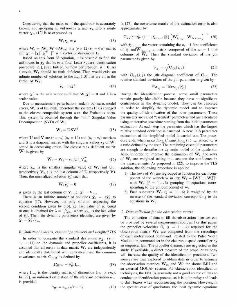
In [27], the covariance matrix of the estimation error is alsoapproximated by
Cχχ ' σ2W
(1 + ||χ1:n−1||22
) (W
T
t1:nt−1Wt1:nt−1
)−1
(20)
with χ1:nt−1 the vector containing the nt−1 first coefficientsof χ andWt1:nt−1
a matrix composed of the nt − 1 firstcolumns of Wt. Then the standard deviation of the jthparameter is given by
σχj=√
Cχχ(j, j) (21)
with Cχχ(j, j) the jth diagonal coefficient of Cχχ. Therelative standard deviation of the jth parameter is given by
%σχj= 100σχj
/|χj | (22)
During the identification process, some small parametersremain poorly identifiable because they have no significantcontribution in the dynamic model. They can be canceledin order to simplify the dynamic model and to improvethe quality of identification of the other parameters. Theseparameters are called “essential” parameters and are calculatedusing an iterative procedure starting from the initial parametersestimation. At each step the parameter which has the largestrelative standard deviation is canceled. A new TLS parameterestimation of the simplified model is carried out. The proce-dure ends when max(%σχj
)/min(%σχj) < rσ , where rσ is
a ratio defined by the user. The remaining essential parametersare enough to describe the dynamic model of the quadrotor.Also, in order to improve the estimation of Wt, the rowsof Wt are weighted taking into account the confidence inthe measurements. As proposed in [22], to improve the TLSsolution, the following procedure is applied
1) The rows of Wt are regrouped as function for each com-ponent of the wrench w in (9): Wt = [WT
1 . . .WT6 ]T
with Wj (j = 1 . . . 6) grouping all equations corre-sponding to the jth component of w.
2) Each submatrix Wj (j = 1 . . . 6) is weighted by theinverse of the standard deviation corresponding to theequations in Wj .
C. Data collection for the observation matrix
The collection of data to fill the observation matrices canbe provided by several measurement sources. For this paper,the propeller velocities Ωi (i = 1 . . . 4) required for theobservation matrix Wk are computed from the recordingsof each motor speed command related to the Pulse WidthModulation command set in the electronic speed controller byan empirical law. The propeller dynamics are neglected in thisstudy. If available, a direct measure of the propeller velocitywill increase the quality of the identification procedure. Twosources are then explored to obtain data in order to estimatethe observation matrices Wm and W: the drone IMU andan external MOCAP system. For classic robot identificationtechniques, the IMU is generally not a good source of data toconduct an identification process, as it is quite noisy and leadsto drift biases when reconstructing the position. However, inthe specific case of quadrotors, the local dynamic equations
5
do not depend on the position of the device. In addition, theorientation only impacts the gravity force which is includedin the accelerometer measurement. Thus it makes the IMU avery good candidate to collect data for the identification ofthe dynamic model of a quadrotor. As a result, we tested twotypes of data collection for Wm and W:
1) Data collection from IMU: The angular velocity ωand the acceleration (including gravity) ad −R−1g aremeasured with the gyroscope and accelerometer, respec-tively. Gyroscope biases are estimated and compensatedby an online Extended Kalman Filter. The angular accel-eration estimation ˆω is obtained by sampling, band-passfiltering the measure of ω with zero-phase noncausalButterworth filter and central difference algorithm [29].Those three vectors are enough to compute the matricesDm and D in (10).
2) Data collection from MOCAP system: The position ζand the orientation coordinates given in Bryant anglesη are measured from the MOCAP system. Their deriva-tives ˆ
ζ, ˆζ, ˆη and ˆη are obtained by sampling, band-pass
filtering with zero-phase noncausal Butterworth filterand central difference algorithm. Then, the accelerationad, the angular velocity and acceleration ω, ω arecomputed respectively from (3) and (4).
Using the IMU as a data source has several advantages. Itdoesn’t require any external sensor in addition to those usuallyavailable on a quadrotor. If the data collection is done onboard,there is also no data synchronization required as the IMU andthe rotor speed data are both available on the UAV. Also thedata collected from the MOCAP must be differentiated twice,while the acceleration is directly collected on the IMU. Wewould expect a better data quality from the IMU, however,depending on the IMU, its calibration and online measurementprocessing, the data may be quite noisy and/or biased. Thisis why we propose a comparison of the two data collectionmethods in this paper.
IV. CASE STUDY
A. Experimental protocol
Experimental validation was performed using a customquadrotor based on a Lynxmotion Crazy2fly frame, withMT2208 brushless DC motors, 12A ESCs, and plastic 8045dual-blade propellers. The controller was a Pixhawk 2.4 run-ning PX4-v1.7.3. Motor speeds and IMU data were gatheredfrom the Pixhawk using an onboard Raspberry Pi 3B+. Thepose of the UAV was gathered using a Qualisys MOCAPsystem with eight cameras. All data was nominally gatheredat 200 Hz.
In order to carry out robot dynamic identification, it isusual to make the robot move along “exciting” trajectories,i.e. optimized reference trajectories that can be computed bynonlinear minimization of a criterion function of the conditionnumber of the observation matrix [30]. However, agressivemaneuvers in automatic flight mode would require a fine tunedcontrol strategy relying on an external system (such as theMOCAP system). The objective of this paper is to propose amethod that does not require specific equipment and so the
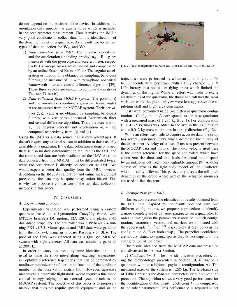
Fig. 2. Test configuration B, were ma = 0.125 kg and mb = 0.042 kg
trajectories were performed by a human pilot. Flights of 60to 90 seconds were performed with a fully charged 11.1 VLiPo battery in a 6×4×4 m flying arena which limited thedynamics of the flights. While an effort was made to exciteall dynamics of the quadrotor, the thrust and roll had the mostvariation while the pitch and yaw were less aggressive due topiloting skill and flight area constraints.
Tests were performed using two different quadrotor config-urations. Configuration A corresponds to the base quadrotorwith a measured mass of 1.285 kg (Fig. 1). For configurationB, a 0.125 kg mass was added to the arm in the +x directionand a 0.042 kg mass to the arm in the -y direction (Fig. 2).
While an effort was made to acquire accurate data, the setuphas several systematic flaws which decreased the quality ofthe experiment. A delay of at least 5 ms was present betweenthe MOCAP data and motors. The motor velocity used hereis the output reference for the speed controllers which havea non-zero rise time, and thus leads the actual motor speedby an unknown but likely non-negligible amount [9]. Anothersource of error is the rigid-body model of the quadrotor,when in reality it flexes. This particularly affects the roll-pitchdynamics of the drone where part of the actuation momentsare used to flex the arms.
B. Identification from IMU
This section presents the identification results obtained fromthe IMU data. Inspired by the results obtained with twodifferent configurations, we propose a procedure to identifya more complete set of dynamic parameter on a quadrotor. Inorder to distinguish the parameters associated to each config-uration, parameters, vectors and matrices are annotated withthe superscripts A, B or AB respectively if they concern theconfiguration A, B or both (resp.). The propeller coefficientsare not associated to superscripts as they do not depend on theconfiguration of the drone.
The results obtained from the MOCAP data are presentedand discussed in the next Section.
1) Configuration A: The first identification procedure, us-ing the methodology presented in Section III, is run on aquadrotor without additional payload (configuration A). Themeasured mass of the system is 1.285 kg. The left-hand sideof Table I presents the dynamic parameters identified with theprocedure. The algorithm shows a very good performance forthe identification of the thrust coefficient kt in comparisonto the other parameters. This performance is required to set

6
TABLE IESSENTIAL PARAMETERS IDENTIFIED FROM IMU DATA (SI BASE UNITS)
Configuration AParam. Value %σχjAmsx -4.32E-03 2.70Amsy -1.95E-03 6.88Amsz -6.16E-03 4.55AIxx 1.69E-02 1.52AIyy 1.76E-02 1.45kt 3.46E-06 0.05
Configuration BParam. Value %σχjBmsx 4.30E-02 0.31Bmsy -2.01E-02 0.80Bmsz -1.22E-02 4.20BIxx 2.43E-02 1.95BIyy 3.58E-02 1.63BIzz 4.75E-02 7.36kt 3.65E-06 0.04kd 5.40E-08 7.68
the ratio rσ (for computing the essential parameters, see Sec-tion III-B) to 250, so to avoid discarding too many parameterswhile selecting the essential ones (see also III-B).
The algorithm discards the dynamic parameters AIxy , AIyzand AIxz . This result is expected as the mobile frame isaligned with the principal axes of inertia of the quadrotor.We can also see that the procedure discards the parameters kdand AIzz . Those parameters are mainly related to the momentalong the local zd axis. To understand why those parametersare discarded, we can have a closer look at the equationrelated to this moment. Using the Table I, we can assumethe hypothesis: Amsx ' 0, Amsy ' 0, AIxx ' AIyy andAIxy = AIyz = AIxz = 0. Under those hypotheses, from(10), we get
AIzzωz ' kd∑i
−sign(Ωi)Ω2i (23)
This equation is independent from all the other dynamicparameters. In addition, the term kd is not present in theother equations of the dynamic model and the AIzz termsare linearly related to AIxx or AIyy in the other equationsof the drone’s moments. This configuration makes the termskd and AIzz completely independent from the other dynamicparameter and, thus, impossible to identify, knowing only themass of the quadrotor. Note that Izz is often approximated asIxx + Iyy for quadrotors due to symmetry, but it is not seenas rigorous within the scope of this paper.
In order to identify the parameters associated with themoment about zd, it is necessary to break the symmetry ofthe quadrotor. Configuration B fills this requirement and willbe used in a second identification procedure.
2) Configuration B: The second identification procedure isrun on a quadrotor with an additional payload that breaks thesymmetry of the device (configuration B). The measured massof the system is 1.452 kg. The right-hand side of Table Ipresents the dynamic parameters identified with our procedure.Since the dynamic symmetry of the quadrotor is broken, theequation of the moment along zd contains now other dynamicparameters in addition to the terms BIzz and kd. This allowsthe algorithm to compute all the dynamic parameters, apartfrom the non diagonal terms of the inertia matrix which stilldo not sufficiently impact the dynamics of the quadrotor.
Since we obtained the torque coefficient kd with the config-uration B, it would be interesting to feed it in the computationof the configuration A to have a more complete identificationof the initial quadrotor (which is the one we want to control
TABLE IIESSENTIAL PARAMETERS ESTIMATED FROM COMBINED IDENTIFICATION
PROCEDURE (SI BASE UNITS)
IMU Data MOCAP DataParam. Value %σχj
Value %σχj%δ
Amsx -4.54E-03 3.35 - - -Amsz -8.31E-03 5.62 - - -AIxx 1.82E-02 1.84 1.88E-02 3.49 3.3AIyy 1.86E-02 1.79 1.93E-02 2.77 3.6AIzz 2.88E-02 4.90 - - -Bmsx 4.28E-02 0.18 4.25E-02 0.15 0.7Bmsy -1.99E-02 0.47 -1.97E-02 0.37 1.0Bmsz -1.30E-02 3.20 -1.20E-02 3.31 7.7BIxx 2.42E-02 1.11 2.42E-02 0.88 0.0BIyy 3.57E-02 0.93 3.84E-02 0.74 7.0BIzz 4.76E-02 3.71 - - -kt 3.63E-06 0.03 3.68E-06 0.02 1.4kd 5.11E-08 3.84 - - -
%δ is the relative difference (in %) between the values identified from IMUdata and those identified from MOCAP data.
at the end), as the propellers coefficients are not modifiedfrom one configuration to another. We could have done thatin two steps, getting the propellers coefficients from theidentification of configuration B then use them as knownvariable in the identification of configuration A. However,computing in cascade the coefficients and then the inertia is notan efficient methodology because the error of identification ofthe coefficients will impact the identification of the inertia. Asa result, in the next section, we propose an observation matrixthat includes both configurations and allows the computationof all the dynamic parameters in a single computation.
3) Combined identification: The combined identificationconsist in solving both identifications for configurations Aand B in a single TLS algorithm. The vector of the unknowndynamic parameters ABχTu =
[χTk
AχT BχT]
is nowcomposed of 20 dynamic parameters: 9 inertia parametersassociated to each configuration (A and B) and 2 parametersfor the propellers coefficients which are not dependent on theconfiguration. The observation matrix ABWt used in the TLSequation is thus:
ABWtABχt = ρ, ABχTt =
[χTu 1
](24)
It is equivalent to Eq. (13) and is then composed of severalobservation matrices as described by the following equation
ABWt =
[AWk
AW 0 AmAWmBWk 0 BW BmBWm
](25)
In order to represent the higher trust we have in the iden-tification of configuration B, an additional weighting wasperformed on the lines of the matrix ABWt associated to theconfiguration B by a coefficient kw > 1 (in this case kw = 2)..
The Table II presents the dynamic parameters identifiedwith the procedure. As desired, the algorithm takes advantageof configuration B to estimate the parameter kd with theconsequence of also allowing the estimation of the parameterAIzz for configuration A.
4) Cross-validation: In order to confirm the relevance ofthe identified parameters, a cross-validation is performed onflight data different from those used in the identificationprocedure. Figures 3 and 4 give the estimations obtained using

7
TABLE IIIRELATIVE ERROR NORMS ||ρ||/||Wkχk|| (%)
Configuration AWrench component Fz Mx My Mz
10.46 46.15 43.73 -Configuration B
Wrench component Fz Mx My Mz
4.40 20.99 10.70 45.19Configuration A - Combined identification
Wrench component Fz Mx My Mz
8.47 47.07 42.96 68.13Configuration B - Combined identification
Wrench component Fz Mx My Mz
3.96 20.96 10.59 46.79
the identified parameters from the combined identification(Section IV-B3). Table III gives the error norm relative to themotor inputs (||ρ||/||Wkχk||) respectively for configurationsA and B for all the identification procedures with the flightdata for cross-validation. We can see that the estimations arecompletely relevant for the thrust. The moments are quite lowin amplitude, so unmodelled effects can have a non-negligibleimpact on the accuracy of the estimations.
These unmodelled effects are several in nature: sensor bi-ases and calibration, experimental recording delays, transitionsstates, body flexibility, aerodynamic effects, battery load, etc.Our estimation method gives the dynamic parameters forthe imperfect dynamic model provided which is confrontedwith real flight data. It leads to the identification of dynamicparameters that may not be the real ones but those best fittedto the dynamic model used. The more precise the model, thecloser to the real dynamic parameters the estimation will be.Nevertheless, in practice, the model provided should be thesame for the identification and for the control law, becausethe identified values for a given model will be those leadingto less modelling errors, and thus the best dynamic behavior.
C. Identification from MOCAP
Identification from MOCAP data was performed. However,worse data quality allowed the identification of fewer param-eters, even with the combined identification procedure. TheTable II shows the identified values for the dynamic parameterswith data collected from the MOCAP system and a comparisonto the data obtained with the IMU. The relative difference upto 7.7 % is quite low considering that the reference framebetween the two sensor systems are not perfectly aligned andthat each system has its own calibration.
V. CONCLUSIONS
In this paper we proposed a method to identify in onesingle procedure the rigid body parameters and thrust andtorque coefficients of a hovering quadrotor from flight data.The procedure does not require any specific benchmark, andrequires only the mass of the quadrotor and a recording offlight data (motor inputs and IMU outputs). The flight did notrequire a specific trajectory and can be performed manuallyby a somewhat skilled human operator as long as it remains
“sufficiently exciting” [31] for the dynamics to be identified.The identification was performed in real flight conditions,giving the best fitting values in presence of perturbations andavoiding biases that may appear on a specific test bench.
We observed that the symmetries of a classic quadrotorlimited the performance of the algorithm and we proposed anextended identification procedure which required two typesof flights: one with the the initial quadrotor and a secondflight with an additional payload on the vehicle that broke themass distribution symmetries of the UAV. This new procedureincreased the performance of the identification and allowed anestimation of all relevant dynamic parameters of the quadrotor.
The procedure has been presented in a near hoveringcontext. Future work includes an extension of the procedureto aerodynamical effects in high speed flight. We believe alsothat it could be adapted to other multi-rotor UAVs.
REFERENCES
[1] D. Mellinger, N. Michael, and V. Kumar, “Trajectory generation andcontrol for precise aggressive maneuvers with quadrotors,” The Interna-tional Journal of Robotics Research, vol. 31, no. 5, pp. 664–674, 2012.
[2] R. Mahony, V. Kumar, and P. Corke, “Multirotor Aerial Vehicles:Modeling, estimation, and control of quadrotor,” IEEE Robotics andAutomation Magazine, vol. 19, no. 3, pp. 20–32, 2012.
[3] J. Wang, T. Raffler, and F. Holzapfel, “Nonlinear position controlapproaches for quadcopters using a novel state representation,” inProceedings of the AIAA Guidance, Navigation, and Control Conference,Minneapolis, Minnesota, USA, aug 2012, pp. 1–17.
[4] K. U. Lee, Y. H. Yun, W. Chang, J. B. Park, and Y. H. Choi,“Modeling and Altitude Control of Quad-rotor UAV,” in Proceedings ofInternational Conference on Control, Automation and Systems, Kintex,Gyeonggi-do, Korea, 2011, pp. 1897–1902.
[5] H. Bouadi, S. Simoes Cunha, A. Drouin, and F. Mora-Camino, “Adaptivesliding mode control for quadrotor attitude stabilization and altitudetracking,” in IEEE 12th International Symposium on ComputationalIntelligence and Informatics, Budapest, Hungary, 2011, pp. 449–455.
[6] H. Voos, “Nonlinear control of a quadrotor micro-uav using feedback-linearization,” in Proceedings of the IEEE International Conference onMechatronics, Malaga, Spain, apr 2009, pp. 1–6.
[7] A. Das, K. Subbarao, and F. Lewis, “Dynamic inversion with zero-dynamics stabilisation for quadrotor control,” IET Control Theory andApplications, vol. 3, no. 3, pp. 303–314, 2008.
[8] A. Mokhtari and A. Benallegue, “Dynamic feedback controller of Eulerangles and wind parameters estimation for a quadrotor unmanned aerialvehicle,” in Proceedings of IEEE International Conference on Roboticsand Automation (ICRA), New Orleans, LA, USA, apr 2004, pp. 2359–2366.
[9] S. Bouabdallah, “Design and control of quadrotors with application toautonomous flying,” Ph.D. dissertation, Ecole polytechnique federale deLausanne, 2007.
[10] M. Elsamanty, A. Khalifa, M. Fanni, A. Ramadan, and A. Abo-Ismail, “Methodology for identifying quadrotor parameters, attitudeestimation and control,” in Proceedings of the IEEE/ASME InternationalConference on Advanced Intelligent Mechatronics (AIM), Wollongong,Australia, jan 2013, pp. 1343–1348.
[11] L. Derafa, T. Madani, and A. Benallegue, “Dynamic modelling andexperimental identification of four rotors helicopter parameters,” in Pro-ceedings of the IEEE International Conference on Industrial Technology,Mumbai, India, jan 2006, pp. 1834–1839.
[12] G. Chowdhary and R. Jategaonkar, “Aerodynamic parameter estima-tion from flight data applying extended and unscented Kalman filter,”Aerospace Science and Technology, vol. 14, no. 2, pp. 106–117, 2010.
[13] N. Abas, A. Legowo, and R. Akmeliawati, “Parameter identificationof an autonomous quadrotor,” in Proceedings of the 4th InternationalConference on Mechatronics (ICOM), Kuala Lumpur, Malaysia, may2011.
[14] P. Lyu, S. Bao, J. Lai, S. Liu, and Z. Chen, “A dynamic model parameteridentification method for quadrotors using flight data,” Proceedings ofthe Institution of Mechanical Engineers, Part G: Journal of AerospaceEngineering, vol. 233, no. 6, pp. 1990–2002, 2019.

8
Fig. 3. Forces/Moments estimations from rigid body dynamics (blue) and rotors model (red) - Cross Validation - Configuration A - Modelling errors arerepresented with the scale on the right.
Fig. 4. Forces/Moments estimations from rigid body dynamics (blue) and rotors model (red) - Cross Validation - Configuration B - Modelling errors arerepresented with the scale on the right.
[15] C. Powers, D. Mellinger, A. Kushleyev, B. Kothmann, and V. Kumar,“Influence of Aerodynamics and Proximity Effects in Quadrotor Flight,”in The 13th International Symposium on Experimental robotics, Quebec,Canada, jun 2012, pp. 289–302.
[16] B. Theys, G. Dimitriadis, T. Andrianne, P. Hendrick, and J. De Schutter,“Wind tunnel testing of a VTOL MAV propeller in tilted operatingmode,” in 2014 International Conference on Unmanned Aircraft Systems(ICUAS). Orlando, FL, USA: IEEE, may 2014, pp. 1064–1072.
[17] D. Kaya and A. T. Kutay, “Modeling and Simulation of a Quadrotorusing Curve Fitting Method,” in AIAA Atmospheric Flight MechanicsConference. Dallas, TX, USA: American Institute of Aeronautics andAstronautics, jun 2015.
[18] S. Sun and C. de Visser, “Aerodynamic Model Identification ofa Quadrotor Subjected to Rotor Failures in the High-Speed FlightRegime,” IEEE Robotics and Automation Letters, vol. 4, no. 4, pp. 3868–3875, 2019.
[19] K. Kozlowski, Modeling and Identification in Robotics. London:Springer, 1996.
[20] M. Gautier and P. Poignet, “Extended Kalman filtering and weightedleast squares dynamic identification of robot,” Control EngineeringPractice, vol. 9, no. 12, pp. 1361–1372, 2001.
[21] W. Khalil and E. Dombre, Modeling, identification and control of robots.Kogan Page Science, 2002.
[22] S. Briot and M. Gautier, “Global identification of joint drive gains anddynamic parameters of parallel robots,” Multibody System Dynamics,vol. 33, no. 1, pp. 3–26, 2015.
[23] S. Sun, C. D. Visser, and Q. P. Chu, “Quadrotor Gray-Box Model
Identification from High-Speed Flight Data Quadrotor Gray-box ModelIdentification from High-Speed Flight Data,” Journal of Aircraft, vol. 56,no. 2, 2019.
[24] J. Diebel, “Representing attitude: Euler angles, unit quaternions, androtation vectors,” Standford University, Tech. Rep., 2006.
[25] P.-J. Bristeau, P. Martin, E. Salaun, and N. Petit, “The role of propelleraerodynamics in the model of a quadrotor UAV,” in Proceedings of theEuropean Control Conference, Budapest, Hungary, aug 2009, pp. 683–688.
[26] S. Bouabdallah, P. Murrieri, and R. Siegwart, “Design and control ofan indoor micro quadrotor,” in Proceedings of the IEEE InternationalConference on Robotics and Automation (ICRA), New Orleans, LA,USA, apr 2004, pp. 4393–4398.
[27] S. Van Huffel and J. Vandewalle, The total least squares problem:Computational aspects and analysis. Philadelphia, PA: SIAM, 1991.
[28] C. R. Rao and H. Toutenburg, Linear models: Least squares andalternatives, second edition. New York: Springer, 1999.
[29] J. Hollerbach, W. Khalil, and M. Gautier, “Model Identification,” inSpringer Handbook of Robotics, B. Siciliano and O. Khatib, Eds.Springer, 2008, ch. 14.
[30] J. Swevers, C. Ganseman, D. B. Tukel, J. de Schutter, and H. Van Brus-sel, “Optimal robot excitation and identification,” IEEE Transactions onRobotics and Automation, vol. 13, no. 5, pp. 730–740, 1997.
[31] C. Presse and M. Gautier, “New criteria of exciting trajectories forrobot identification,” in Proceedings of IEEE International Conferenceon Robotics and Automation, Atlanta, GA, USA, 1993, pp. 907–912.