Embed Size (px)
Citation preview
Transformer ProtectionTransformer Protection
Scott R. Secrest, PEDirector of Engineering
PES Boston Chapter Transformer Seminar
Power Transformer ProtectionPower Transformer Protection
1. Protection Philosophies2. Overvoltage Protection3. Overcurrent and Thermal Protection
a. Transformer Damage Curvea a s o e a age Cu eb. Fuse Protectionc. Overcurrent Relay Protectiond Differential Protectiond. Differential Protectione. Thermal Protectionf. Gas Pressure
4 Monitoring and On Line Diagnostics4. Monitoring and On‐Line Diagnostics
PES Boston Chapter Transformer Seminar
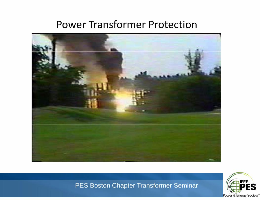
Power Transformer ProtectionPower Transformer Protection
PES Boston Chapter Transformer Seminar
Transformer Protection PhilosophiesTransformer Protection Philosophies
1. Reasons to provide transformer protectiond l la. Detect and Isolate Faulty Equipment
b. Maintain System Stabilityc. Limit Damaged. Minimize Fire Riske. Minimize Risk to Personnel
2. Factors Affecting Transformer Protectiona. Cost of Repairb. Cost of Down Timeb. Cost of Down Timec. Affects on the Rest of the Systemd. Potential to Damage Adjacent Equipmente Length of Time to Repair or Replacee. Length of Time to Repair or Replace
PES Boston Chapter Transformer Seminar
Transformer Protection PhilosophiesTransformer Protection Philosophies3. Basic Tenets of Protection
a. Speeda. Speedb. Sensitivityc. Reliabilityd Securityd. Security
4. Applicable Standardsa C57 12 00 – IEEE Standard General Requirements for Liquid‐Immerseda. C57.12.00 IEEE Standard General Requirements for Liquid‐Immersed
Distribution, Power, and Regulating Transformersb. C57.12.80 – IEEE Standard Terminology for Power and Distribution
TransformersTransformersc. C57.109 ‐ IEEE Guide for Liquid‐Immersed Transformer Through‐Fault‐
Current Durationd C37 91 IEEE Guide for Protecting Power Transformersd. C37.91 – IEEE Guide for Protecting Power Transformerse. C62.22 – IEEE Guide for the Application of Metal‐Oxide Surge Arresters for
Alternating‐Current Systems
PES Boston Chapter Transformer Seminar
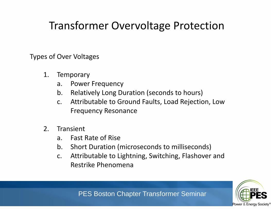
Transformer Overvoltage ProtectionTransformer Overvoltage Protection
f lTypes of Over Voltages
1. Temporarya. Power Frequencyb. Relatively Long Duration (seconds to hours)c. Attributable to Ground Faults, Load Rejection, Low , j ,
Frequency Resonance
2 Transient2. Transienta. Fast Rate of Riseb. Short Duration (microseconds to milliseconds)c Attributable to Lightning Switching Flashover andc. Attributable to Lightning, Switching, Flashover and
Restrike Phenomena
PES Boston Chapter Transformer Seminar
Transformer Overvoltage ProtectionTransformer Overvoltage Protection
Considerations for Overvoltage Protection
Temporary Overvoltage Levels and DurationEquipment BILSystem Grounding
PES Boston Chapter Transformer Seminar
Transformer Overcurrent ProtectionTransformer Overcurrent Protection
PES Boston Chapter Transformer Seminar
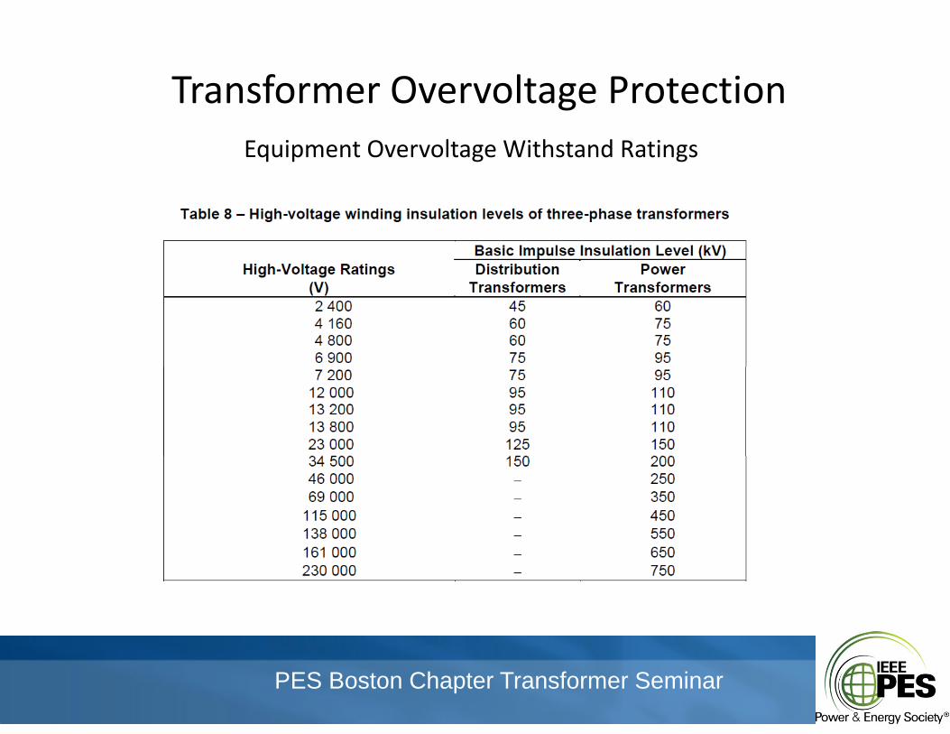
Transformer Overvoltage ProtectionTransformer Overvoltage ProtectionEquipment Overvoltage Withstand Ratings
PES Boston Chapter Transformer Seminar
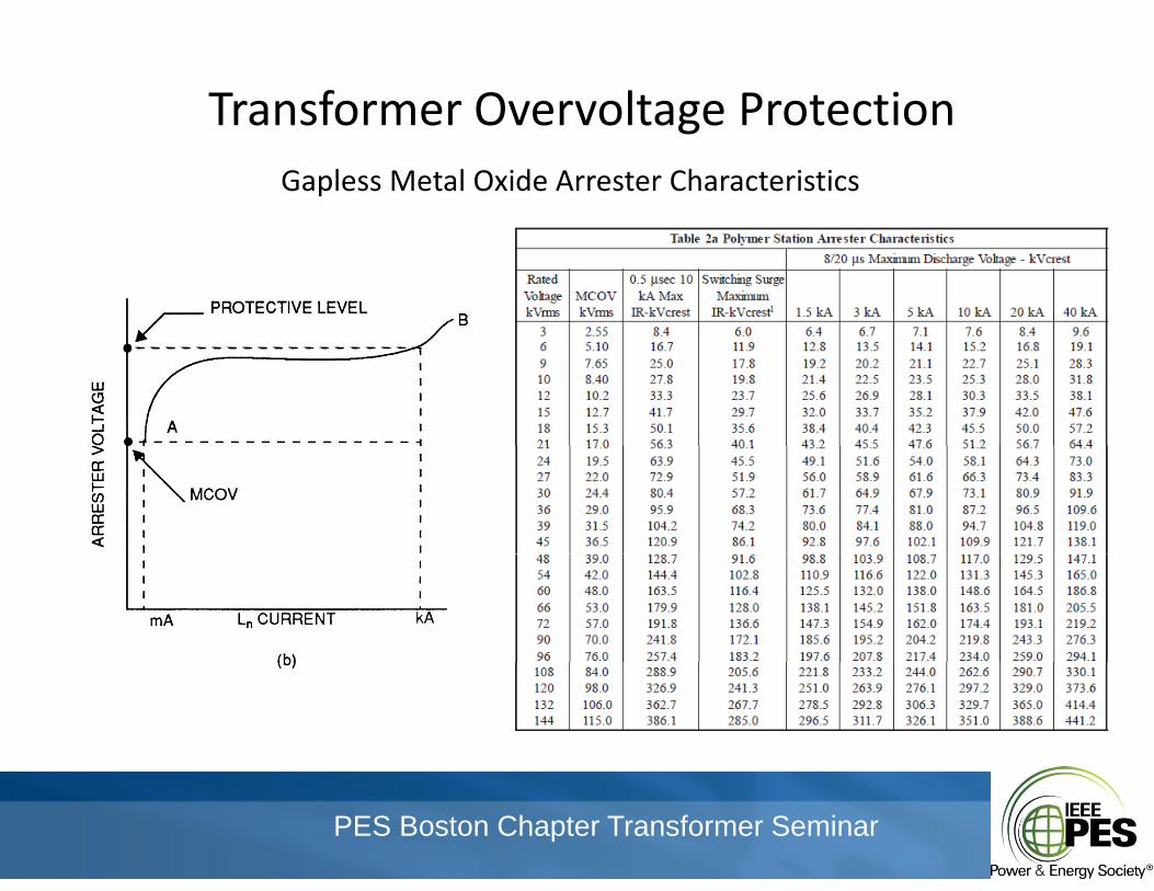
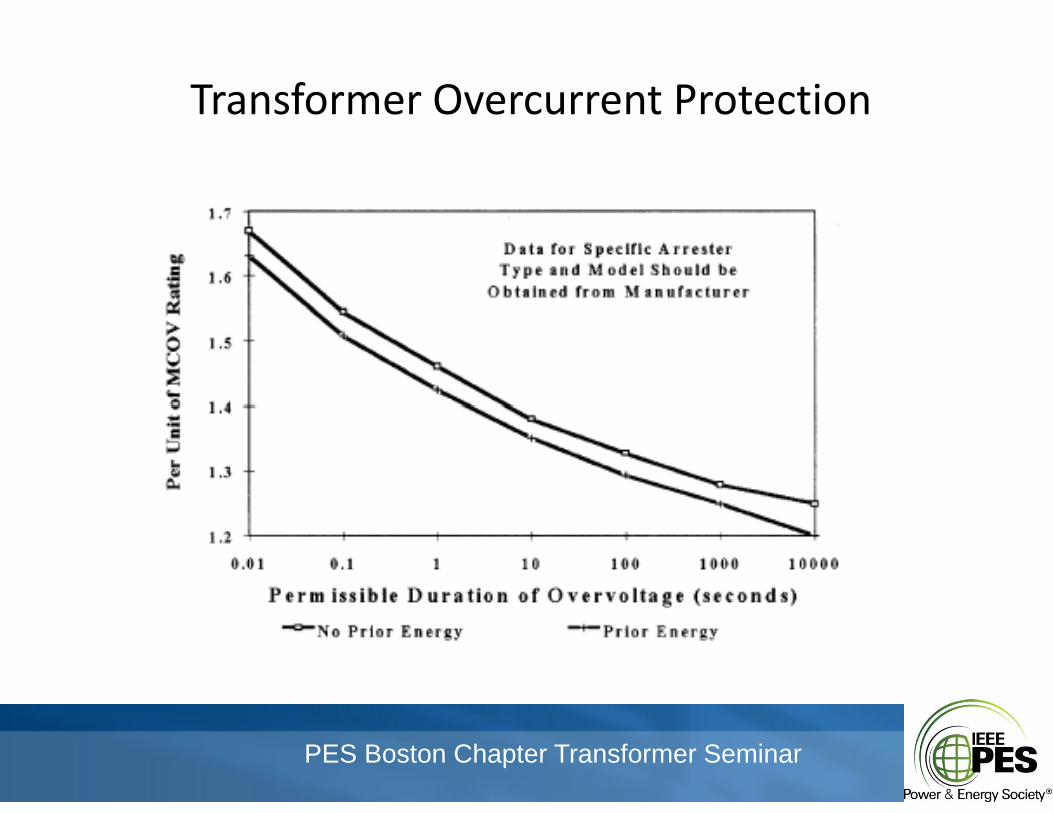
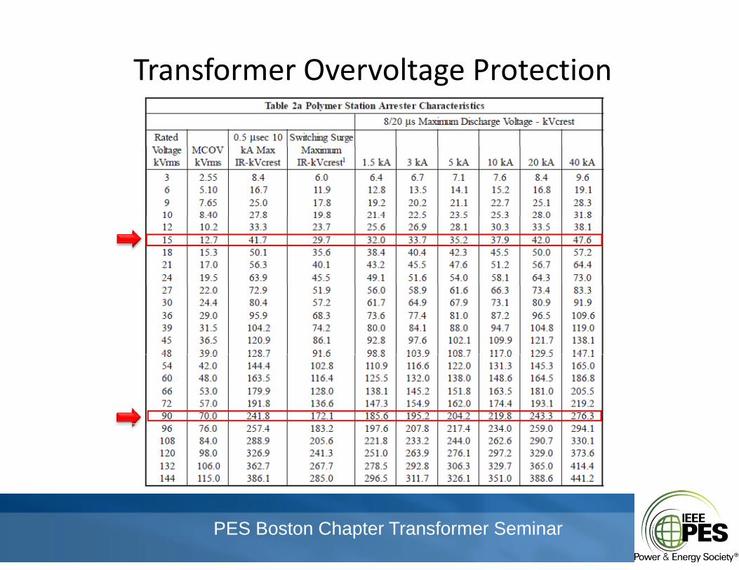
Transformer Overvoltage ProtectionTransformer Overvoltage ProtectionGapless Metal Oxide Arrester Characteristics
PES Boston Chapter Transformer Seminar
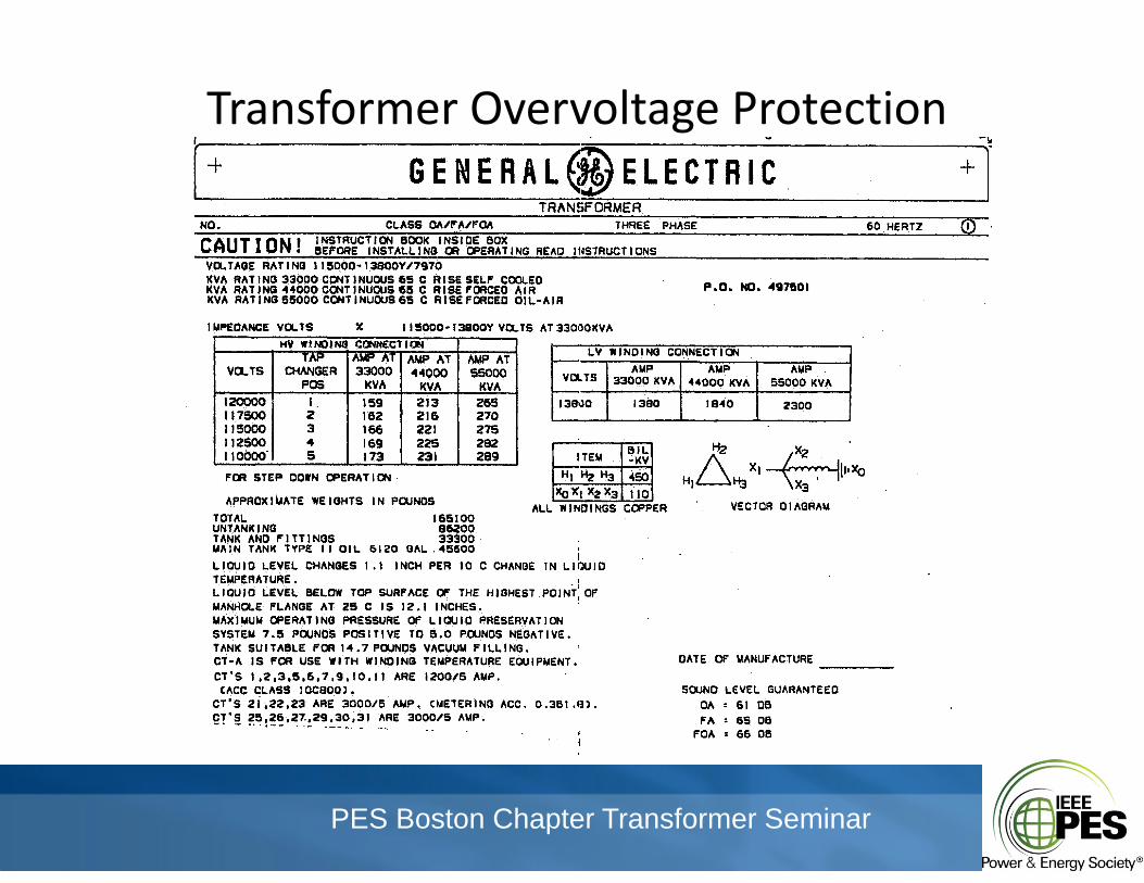
Transformer Overvoltage ProtectionTransformer Overvoltage Protection
PES Boston Chapter Transformer Seminar
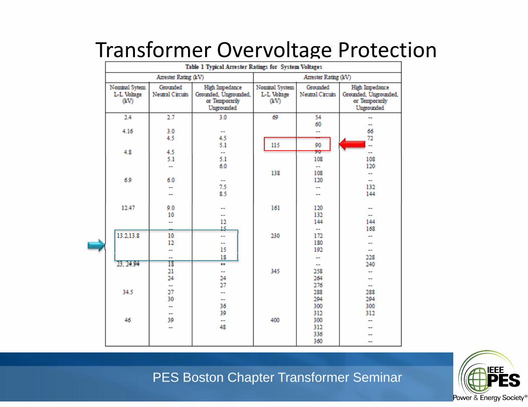
Transformer Overvoltage ProtectionTransformer Overvoltage Protection
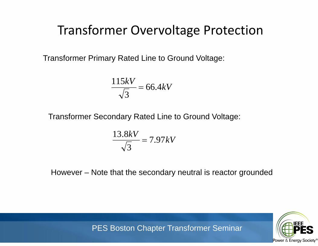
Transformer Primary Rated Line to Ground Voltage:
kVkV 4.663
115
3
Transformer Secondary Rated Line to Ground Voltage:
kVkV 97.73
8.13
However – Note that the secondary neutral is reactor grounded
PES Boston Chapter Transformer Seminar
Transformer Overvoltage ProtectionTransformer Overvoltage Protection
PES Boston Chapter Transformer Seminar
Transformer Overvoltage ProtectionTransformer Overvoltage Protection
PES Boston Chapter Transformer Seminar
Transformer Overcurrent ProtectionTransformer Overcurrent Protection
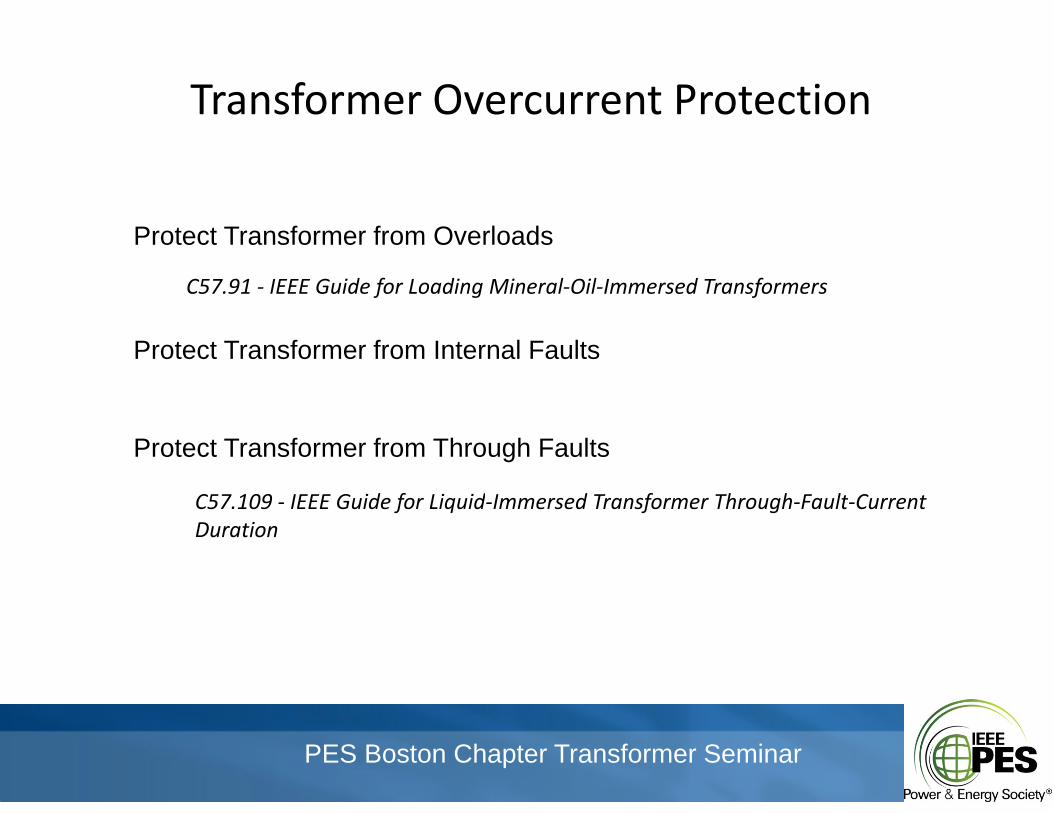
Protect Transformer from Overloads
C57.91 ‐ IEEE Guide for Loading Mineral‐Oil‐Immersed Transformers
Protect Transformer from Internal Faults
Protect Transformer from Through Faults
C57 109 ‐ IEEE Guide for Liquid‐Immersed Transformer Through‐Fault‐CurrentC57.109 IEEE Guide for Liquid Immersed Transformer Through Fault Current Duration
PES Boston Chapter Transformer Seminar
Transformer Overcurrent ProtectionTransformer Overcurrent Protection
PES Boston Chapter Transformer Seminar
Transformer Overcurrent ProtectionTransformer Overcurrent Protection
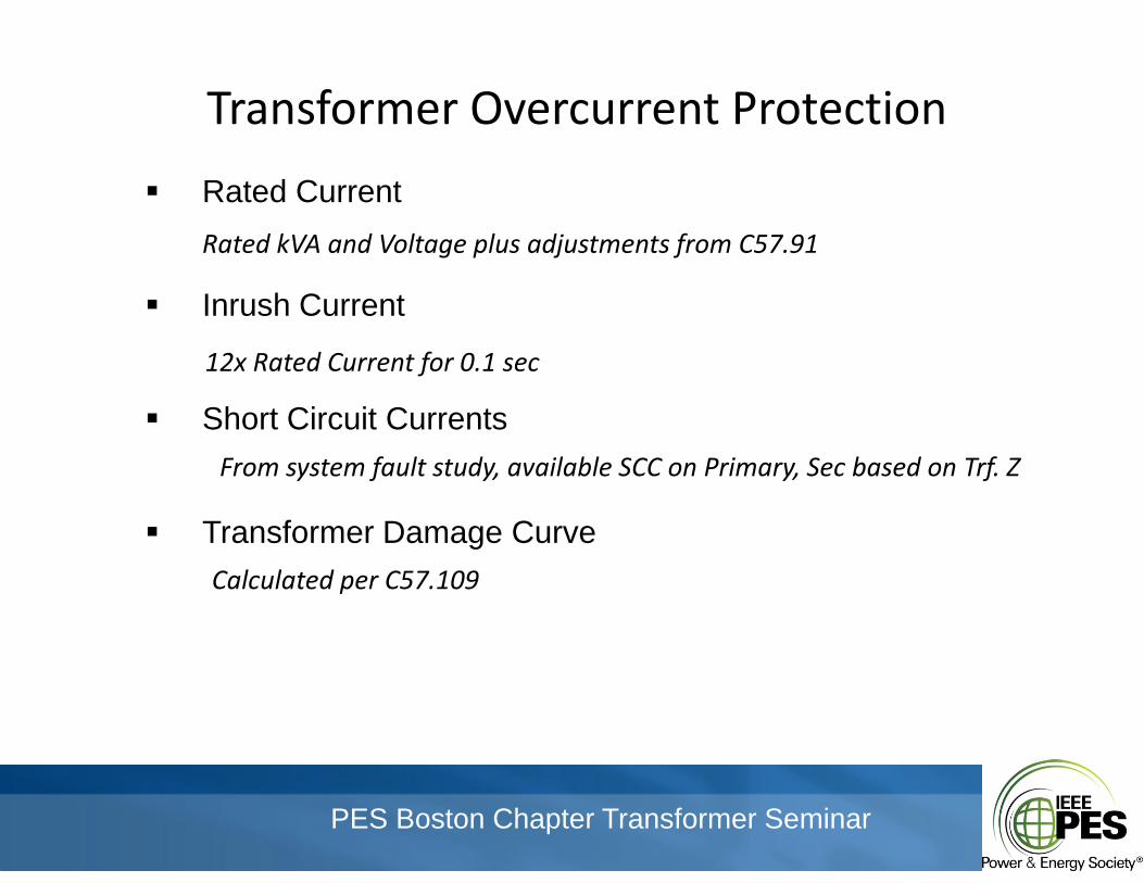
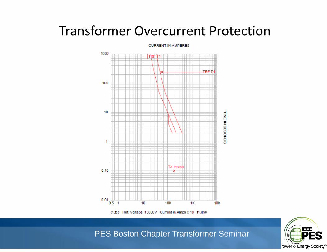
Rated Current
Inrush Current
Rated kVA and Voltage plus adjustments from C57.91
Short Circuit Currents
12x Rated Current for 0.1 sec
Transformer Damage Curve
From system fault study, available SCC on Primary, Sec based on Trf. Z
gCalculated per C57.109
PES Boston Chapter Transformer Seminar
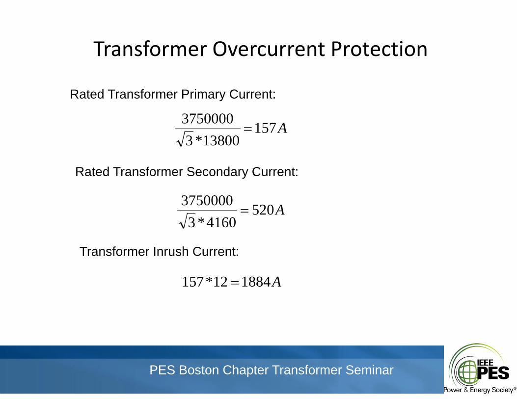
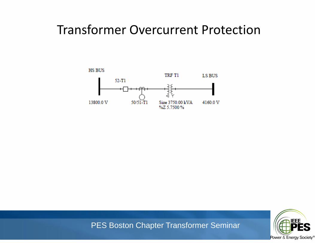
Transformer Overcurrent ProtectionTransformer Overcurrent Protection
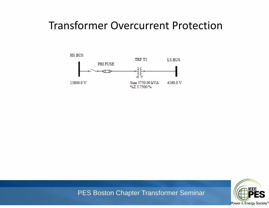
Rated Transformer Primary Current:
A15713800*3
3750000
Rated Transformer Secondary Current:
3750000 A5204160*3
3750000
T f I h C tTransformer Inrush Current:
A188412*157
PES Boston Chapter Transformer Seminar
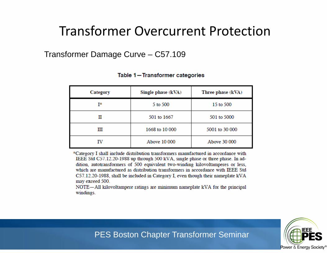
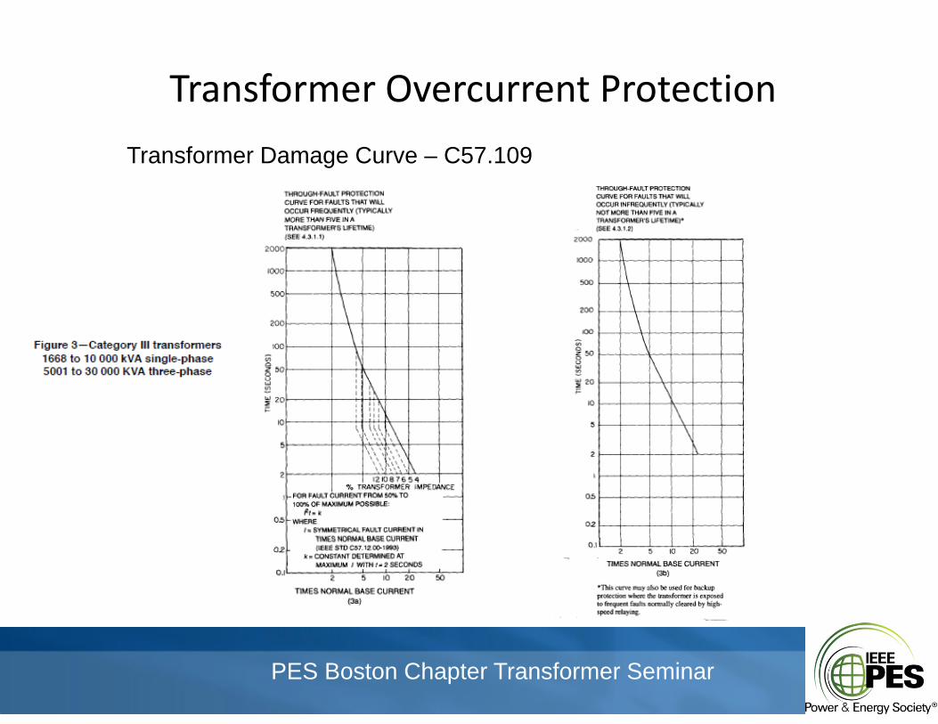
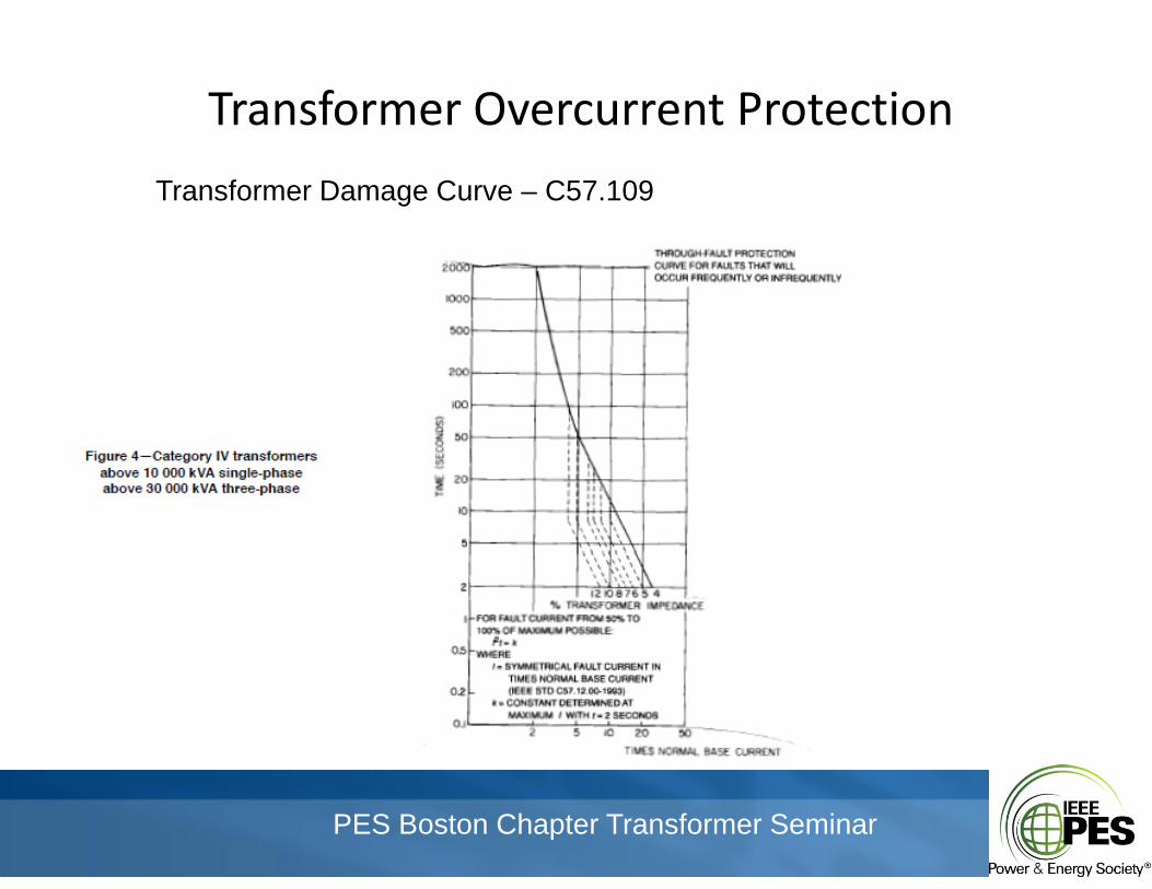
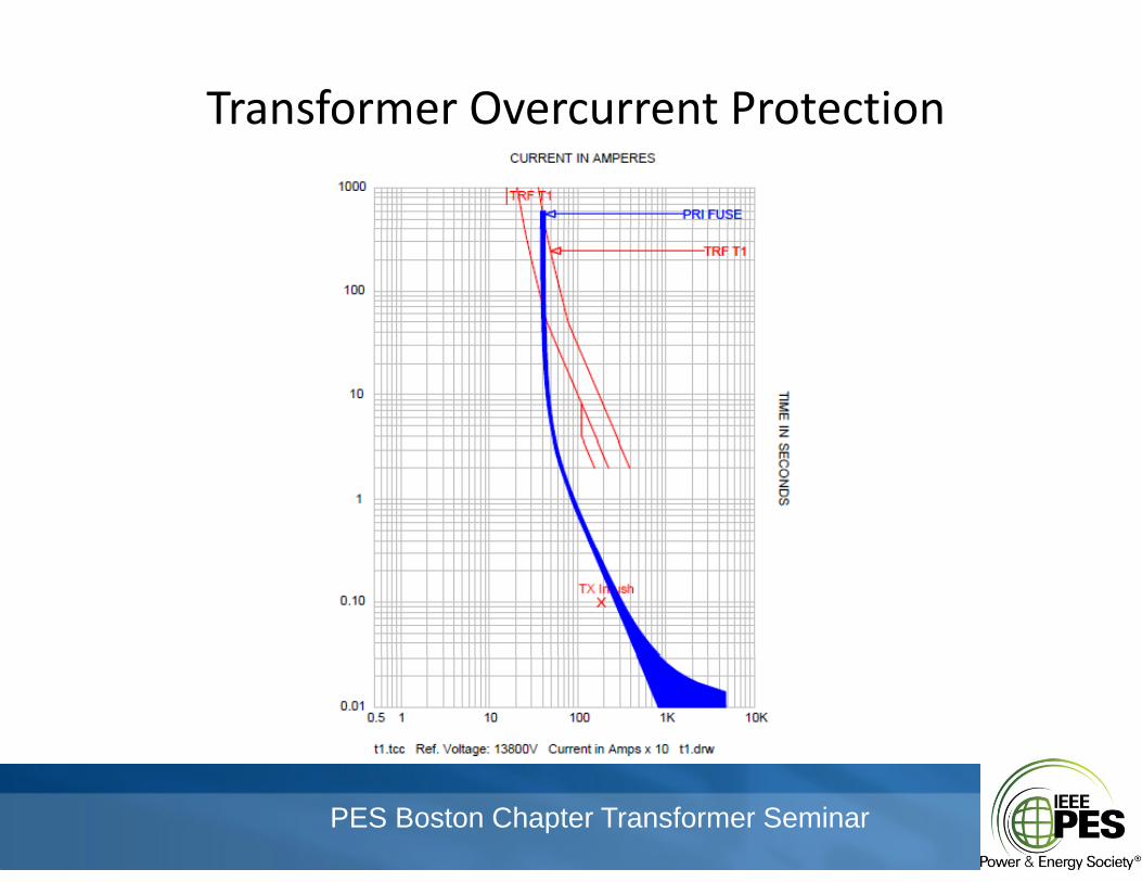
Transformer Overcurrent ProtectionTransformer Overcurrent Protection
Transformer Damage Curve – C57.109
PES Boston Chapter Transformer Seminar
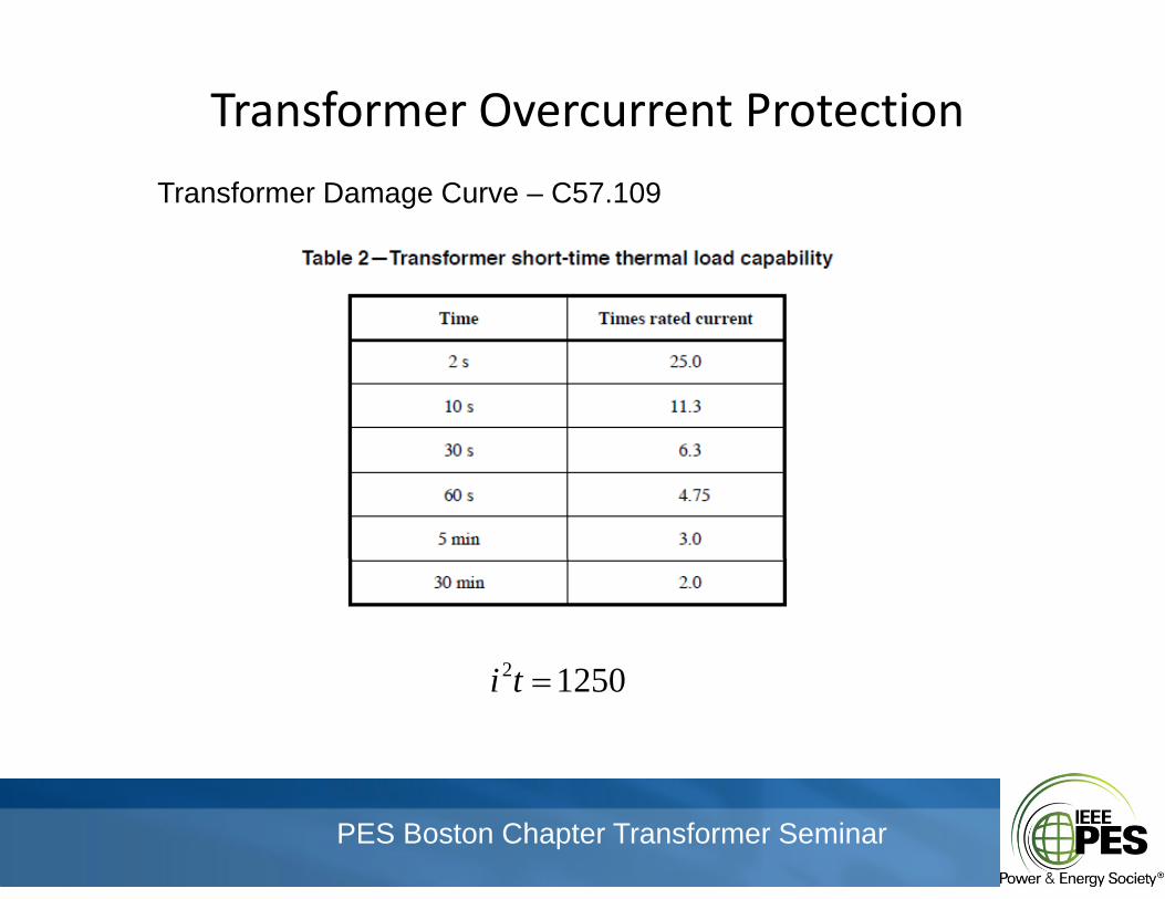
Transformer Overcurrent ProtectionTransformer Overcurrent Protection
Transformer Damage Curve – C57.109
12 02 12502 ti
PES Boston Chapter Transformer Seminar
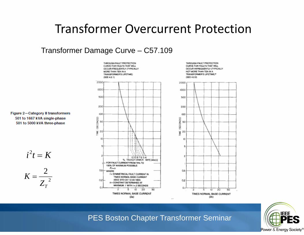
Transformer Overcurrent ProtectionTransformer Overcurrent Protection
Transformer Damage Curve – C57.109
Kti 2
2K 2TZ
K
PES Boston Chapter Transformer Seminar
Transformer Overcurrent ProtectionTransformer Overcurrent Protection
Transformer Damage Curve – C57.109
PES Boston Chapter Transformer Seminar
Transformer Overcurrent ProtectionTransformer Overcurrent Protection
Transformer Damage Curve – C57.109
PES Boston Chapter Transformer Seminar
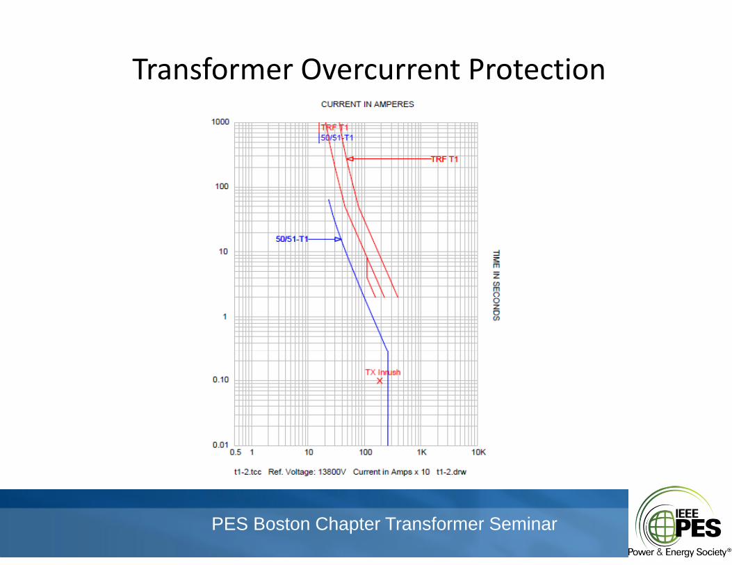
Transformer Overcurrent ProtectionTransformer Overcurrent Protection
PES Boston Chapter Transformer Seminar
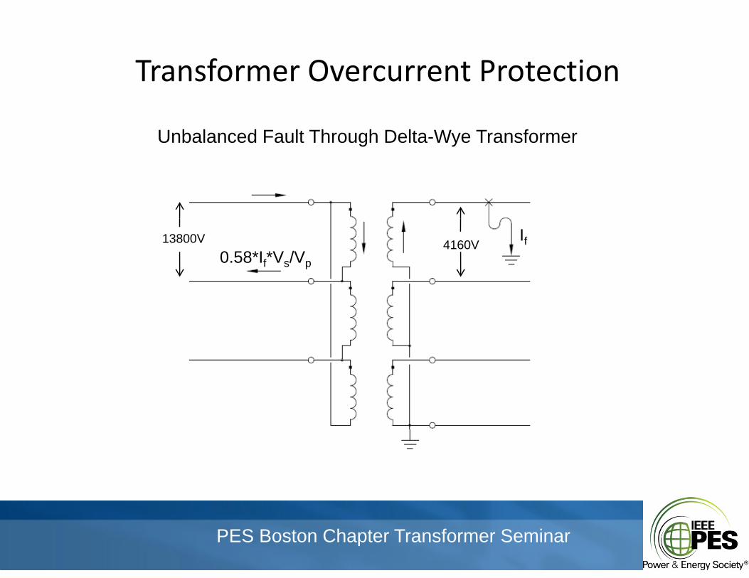
Transformer Overcurrent ProtectionTransformer Overcurrent Protection
Unbalanced Fault Through Delta-Wye Transformer
4160V13800V If0.58*If*Vs/Vp
PES Boston Chapter Transformer Seminar
Transformer Overcurrent ProtectionTransformer Overcurrent Protection
PES Boston Chapter Transformer Seminar
Transformer Overcurrent ProtectionTransformer Overcurrent Protection
PES Boston Chapter Transformer Seminar
Transformer Overcurrent ProtectionTransformer Overcurrent Protection
PES Boston Chapter Transformer Seminar
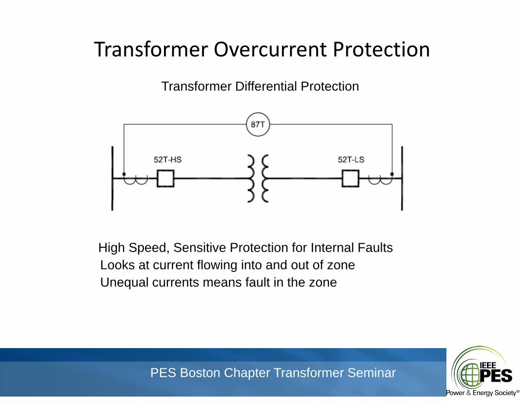
Transformer Overcurrent ProtectionTransformer Overcurrent Protection
Transformer Differential Protection
High Speed Sensitive Protection for Internal FaultsHigh Speed, Sensitive Protection for Internal FaultsLooks at current flowing into and out of zoneUnequal currents means fault in the zone
PES Boston Chapter Transformer Seminar
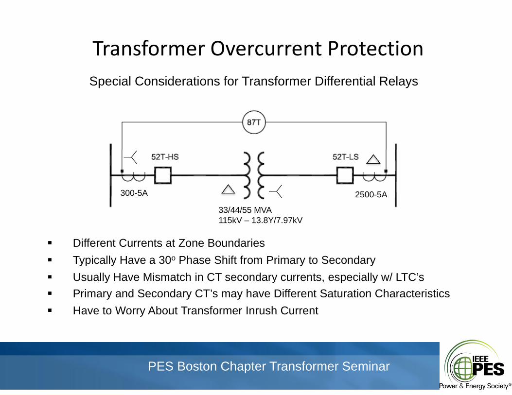
Transformer Overcurrent ProtectionTransformer Overcurrent ProtectionSpecial Considerations for Transformer Differential Relays
300-5A 2500-5A
33/44/55 MVA115kV – 13.8Y/7.97kV
Different Currents at Zone BoundariesDifferent Currents at Zone Boundaries Typically Have a 30o Phase Shift from Primary to Secondary Usually Have Mismatch in CT secondary currents, especially w/ LTC’s Primary and Secondary CT’s may have Different Saturation Characteristics Primary and Secondary CT s may have Different Saturation Characteristics Have to Worry About Transformer Inrush Current
PES Boston Chapter Transformer Seminar
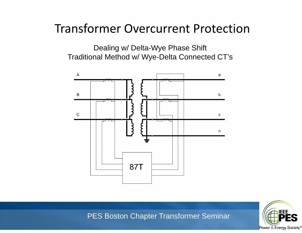
Transformer Overcurrent ProtectionTransformer Overcurrent ProtectionDealing w/ Delta-Wye Phase Shift
Traditional Method w/ Wye-Delta Connected CT’sy
PES Boston Chapter Transformer Seminar
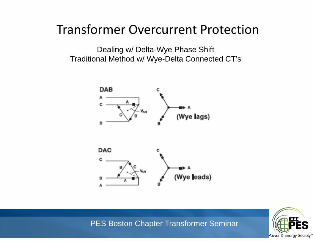
Transformer Overcurrent ProtectionTransformer Overcurrent ProtectionDealing w/ Delta-Wye Phase Shift
Traditional Method w/ Wye-Delta Connected CT’sy
PES Boston Chapter Transformer Seminar
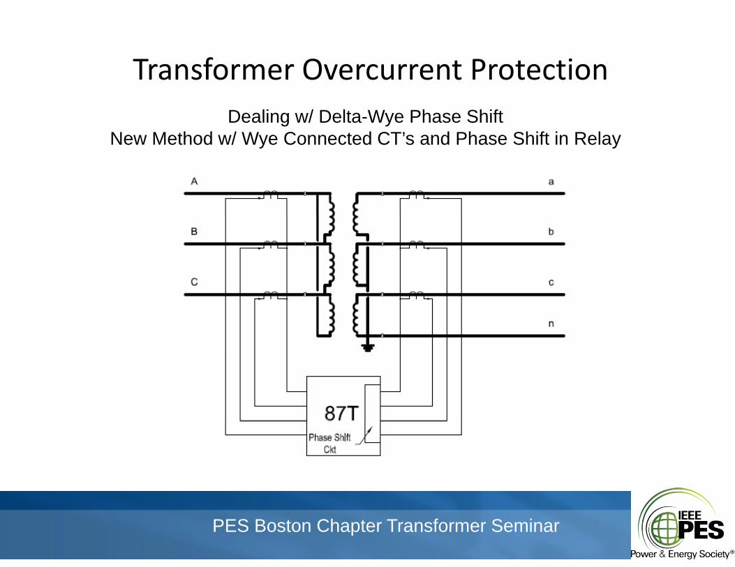
Transformer Overcurrent ProtectionTransformer Overcurrent ProtectionDealing w/ Delta-Wye Phase Shift
New Method w/ Wye Connected CT’s and Phase Shift in Relayy y
PES Boston Chapter Transformer Seminar
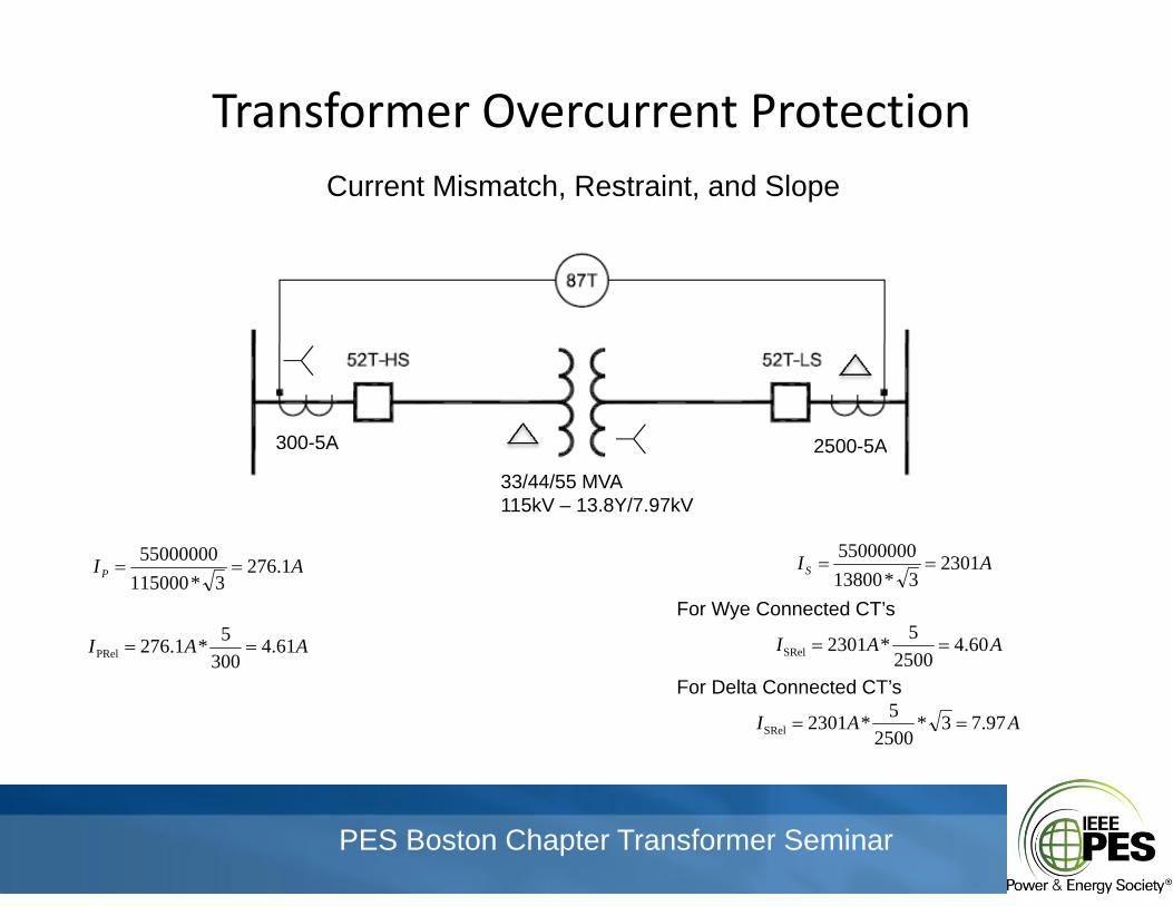
Transformer Overcurrent ProtectionTransformer Overcurrent ProtectionCurrent Mismatch, Restraint, and Slope
300-5A 2500-5A
33/44/55 MVA115kV – 13.8Y/7.97kV
AI 127655000000 AI 230155000000AIP 1.276
3*115000
AAI 61.43005*1.276PRel
AIS 23013*13800
AAI 60.42500
5*2301SRel
For Wye Connected CT’s
AAI 97.73*2500
5*2301SRel
For Delta Connected CT’s
PES Boston Chapter Transformer Seminar
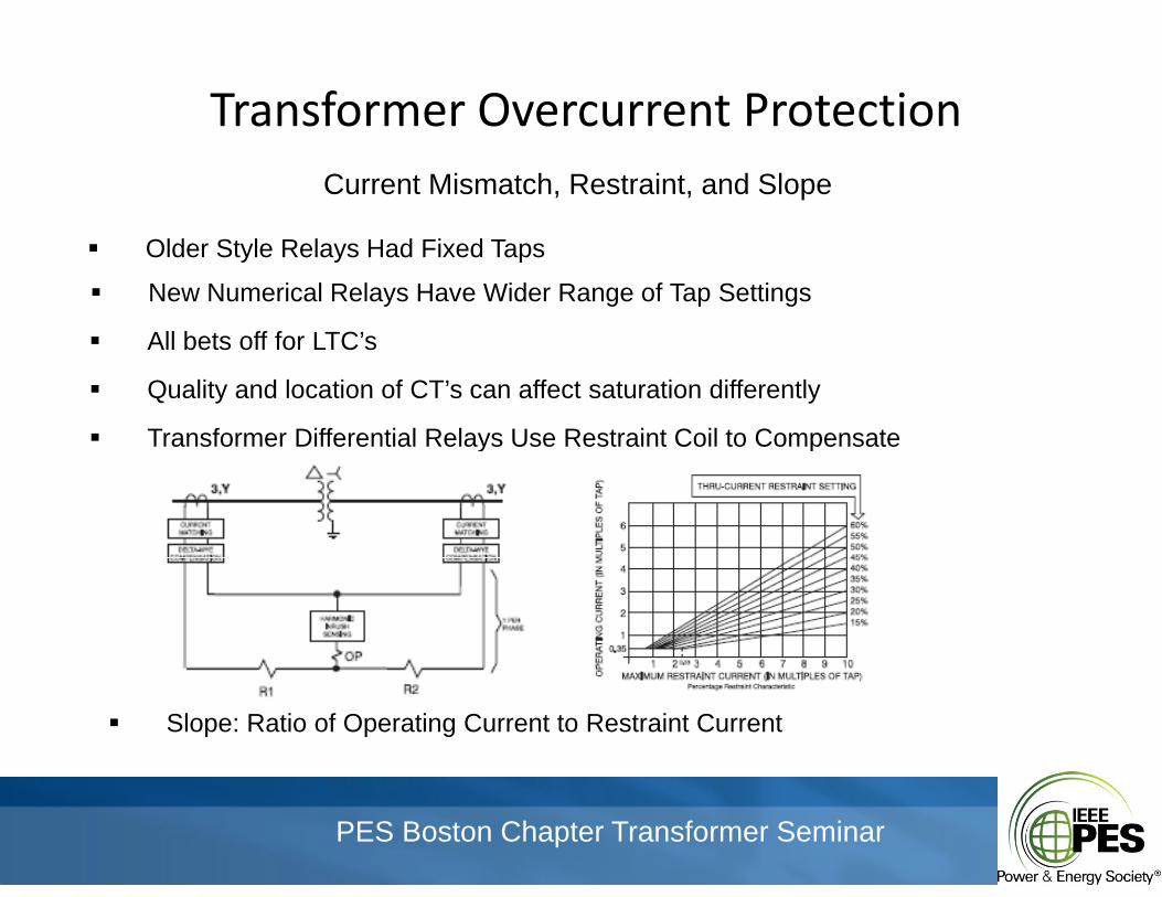
Transformer Overcurrent ProtectionTransformer Overcurrent ProtectionCurrent Mismatch, Restraint, and Slope
Older Style Relays Had Fixed Taps
New Numerical Relays Have Wider Range of Tap Settings
All bets off for LTC’s All bets off for LTC s
Quality and location of CT’s can affect saturation differently
Transformer Differential Relays Use Restraint Coil to Compensatey p
Slope: Ratio of Operating Current to Restraint Current
PES Boston Chapter Transformer Seminar
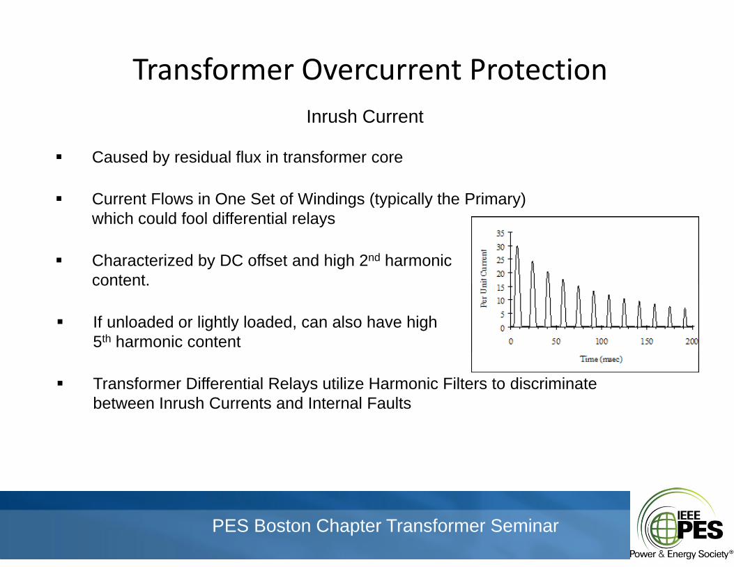
Transformer Overcurrent ProtectionTransformer Overcurrent ProtectionInrush Current
Caused by residual flux in transformer core
Current Flows in One Set of Windings (typically the Primary)hi h ld f l diff ti l lwhich could fool differential relays
Characterized by DC offset and high 2nd harmoniccontentcontent.
If unloaded or lightly loaded, can also have high 5th harmonic content
Transformer Differential Relays utilize Harmonic Filters to discriminatebetween Inrush Currents and Internal Faults
PES Boston Chapter Transformer Seminar
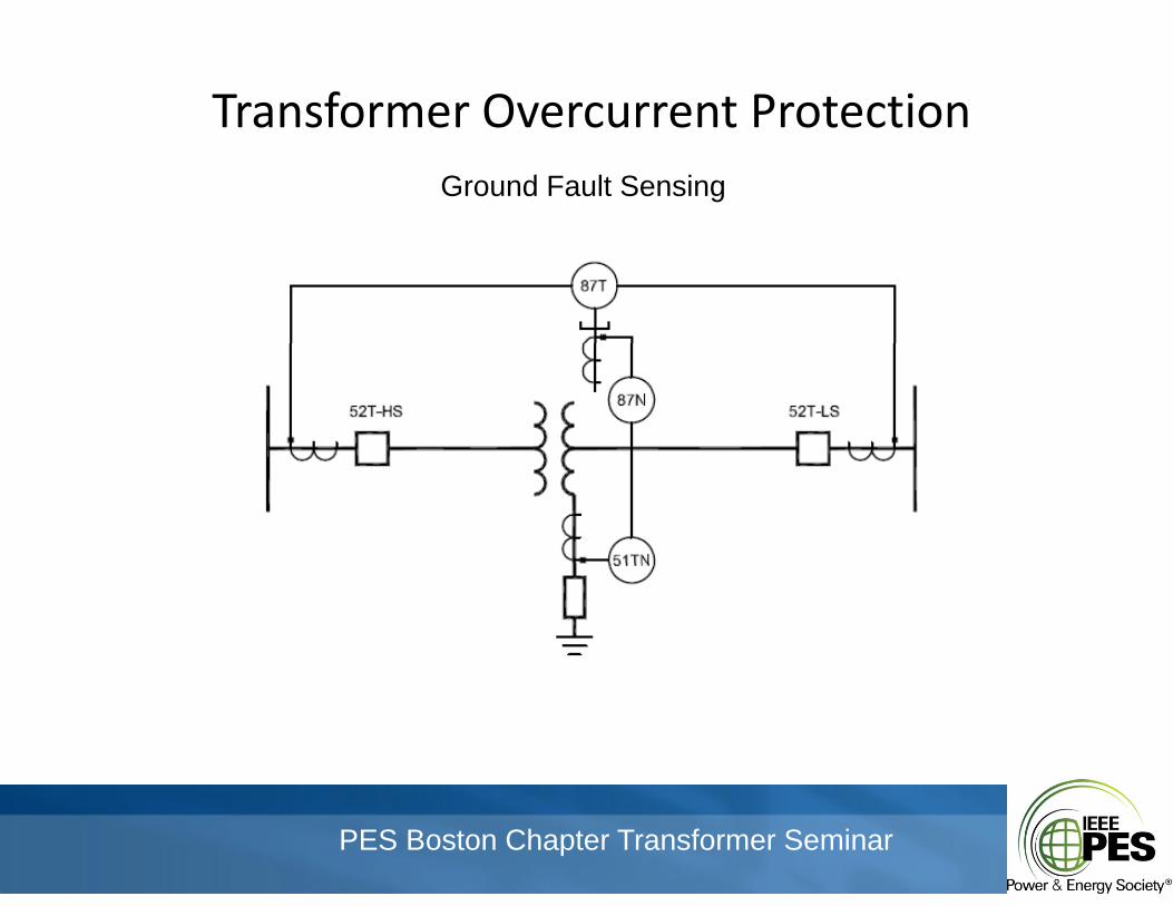
Transformer Overcurrent ProtectionTransformer Overcurrent ProtectionGround Fault Sensing
PES Boston Chapter Transformer Seminar
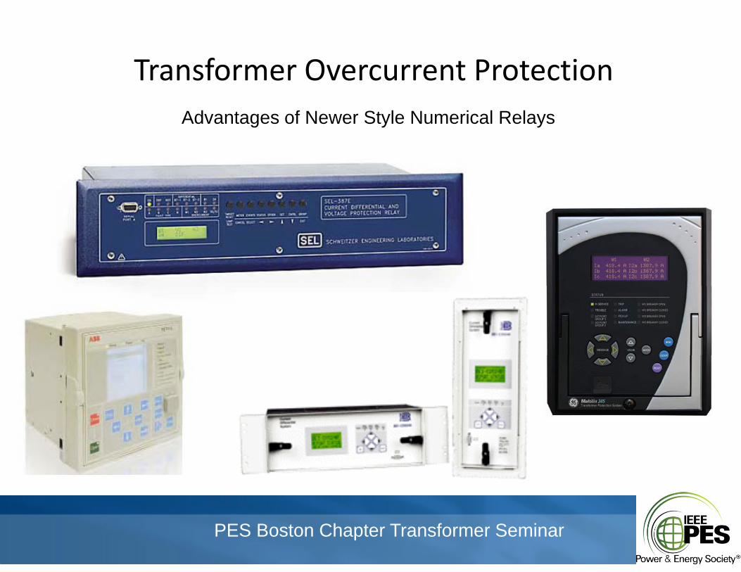
Transformer Overcurrent ProtectionTransformer Overcurrent ProtectionAdvantages of Newer Style Numerical Relays
PES Boston Chapter Transformer Seminar
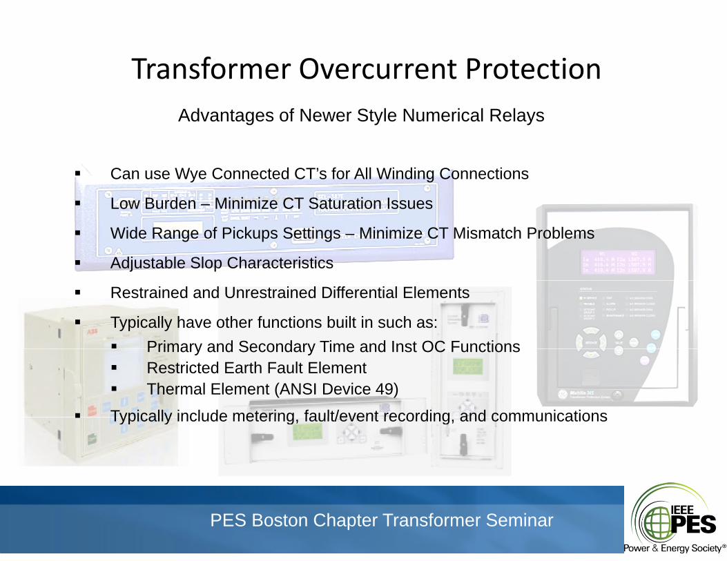
Transformer Overcurrent ProtectionTransformer Overcurrent ProtectionAdvantages of Newer Style Numerical Relays
Can use Wye Connected CT’s for All Winding Connections
Low Burden – Minimize CT Saturation Issues
Wide Range of Pickups Settings – Minimize CT Mismatch Problems
Adjustable Slop Characteristics
Restrained and Unrestrained Differential Elements
Typically have other functions built in such as: Primary and Secondary Time and Inst OC FunctionsPrimary and Secondary Time and Inst OC Functions Restricted Earth Fault Element Thermal Element (ANSI Device 49)
Typically include metering fault/event recording and communications Typically include metering, fault/event recording, and communications
PES Boston Chapter Transformer Seminar
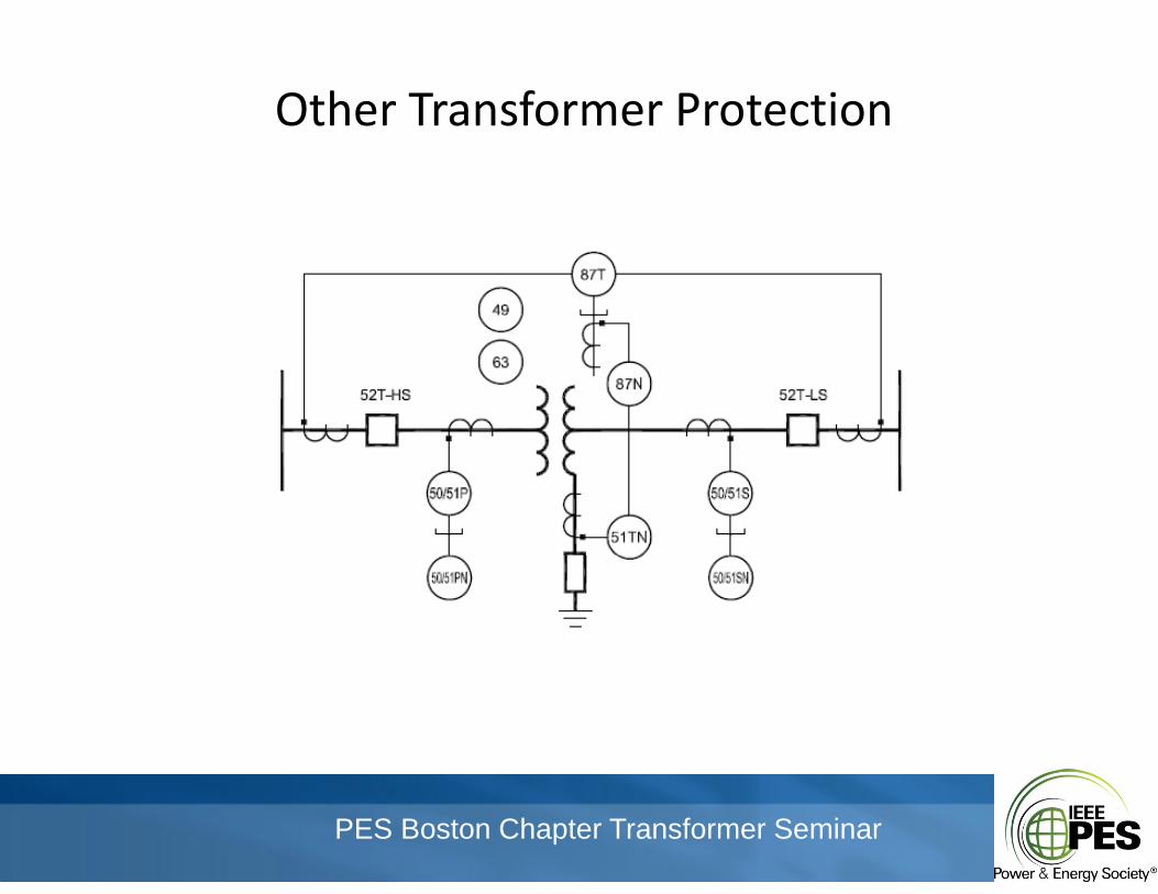
Other Transformer ProtectionOther Transformer Protection
PES Boston Chapter Transformer Seminar
Other Transformer ProtectionOther Transformer Protection
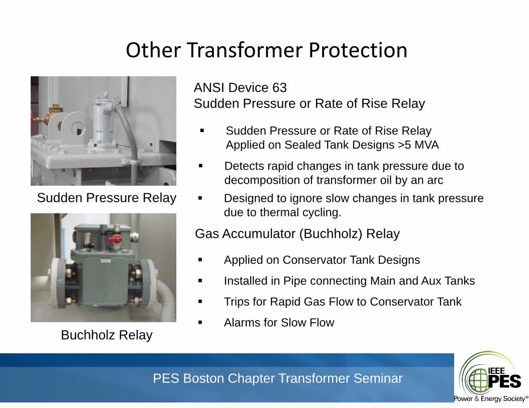
ANSI Device 63Sudden Pressure or Rate of Rise RelaySudden Pressure or Rate of Rise Relay
Sudden Pressure or Rate of Rise RelayApplied on Sealed Tank Designs >5 MVA
Sudden Pressure Relay
Detects rapid changes in tank pressure due todecomposition of transformer oil by an arc
Designed to ignore slow changes in tank pressurey g g g pdue to thermal cycling.
Gas Accumulator (Buchholz) Relay
Applied on Conservator Tank Designs
Installed in Pipe connecting Main and Aux Tanks
Trips for Rapid Gas Flow to Conservator Tank
Buchholz Relay
Trips for Rapid Gas Flow to Conservator Tank
Alarms for Slow Flow
PES Boston Chapter Transformer Seminar
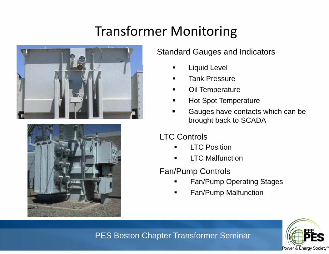
Transformer MonitoringTransformer MonitoringStandard Gauges and Indicators
Li id L l Liquid Level Tank Pressure Oil Temperature Hot Spot Temperature Gauges have contacts which can be
brought back to SCADA
LTC Controls LTC Position LTC Malfunction LTC Malfunction
Fan/Pump Controls Fan/Pump Operating Stages Fan/Pump Malfunction
PES Boston Chapter Transformer Seminar
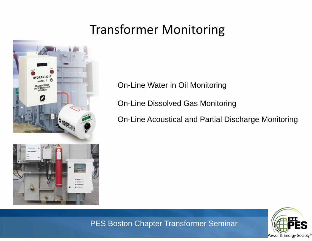
Transformer MonitoringTransformer Monitoring
On-Line Water in Oil Monitoring
On-Line Dissolved Gas Monitoring
On-Line Acoustical and Partial Discharge MonitoringOn Line Acoustical and Partial Discharge Monitoring
PES Boston Chapter Transformer Seminar