Embed Size (px)
Citation preview
155
Tran
sfor
mer
Pro
tect
ion
g Digital Energy
• Secure high-speed protection for transformers, compliant with IEEE C37.91
• Complete IEC 61850 Process Bus solution providing resource optimization and minimizing total P&C life cycle costs
• Improved security for transformer energization and inrush provided through a superior Adaptive 2nd Harmonic Restraint algorithm
• Ambient temperature monitoring with alarming when outside temperature exceeds upper thresholds
• Integrated transformer thermal monitoring for asset management maintenance optimization
• Sensitive ground fault protection provides low impedance differential protection down to 5% of the winding to limit transformer damage
• Robust network security enabling Critical Infrastructure Protection through user command logging, and dual permission access control
• Advanced automation capabilities for providing customized protection and control solutions
• Advanced fault and disturbance recording, including internal relay operating signals thus eliminating the need for redundant recording devices
• Reduced relay to relay wiring and associated installation costs through high-speed inter-relay communications
• Transformer asset monitoring using Hottest Spot, Loss-of-Life and Aging Factor
• Applicable for transformers with windings in a ring bus or breaker-and-a-half configuration
• Reliable and secure protection for three-phase transformers, autotransformers, reactors, split phase and phase angle regulating transformers
• Stand-alone or component in automated substation control system
• Metering - current, voltage, power, energy, frequency, temperature, transformer monitoring
• P & M Class synchrophasors of voltage, current and sequence components – 1 to 120 frames/sec
• Oscillography – analog and digital at 64 samples/cycle • Event Recorder - 1024 time tagged events with 0.5ms scan of
digital inputs• Data Logger - 16 channels with sampling rate up to
1 sample / cycle• Security Audit Trail for tracking changes to T60 configuration
Monitoring and Metering
Protection and Control• Dual slope, dual breakpoint differential restraint
characteristic restrained and unrestrained differential• 2nd harmonic inrush and overexcitation inhibit• Transformer overexcitation and thermal overload protection• Restricted ground fault• Loss-of-Life, Aging Factor, Hottest Spot• 3 zone back-up distance protection with power swing
detection and load encroachment function• Synchrocheck
Communications• Networking interfaces – 100Mbit Fiber Optic Ethernet, RS485,
RS232, RS422, G.703, C37.94• Multiple Protocols - IEC 61850, DNP 3.0 Level 2, Modbus RTU,
Modbus TCP/IP, IEC 60870-5-104, Ethernet Global Data (EGD)• Direct I/O – secure, high-speed exchange of data between
URs for Direct Transfer Trip applications• Embedded Managed Ethernet Switch with 4 - 100 Mbit Fiber
optic ports and 2 copper ports
FEATURESFEATURES
APPLICATIONS
KEY BENEFITS
EnerVista™ Software• Graphical Logic Designer and Logic Monitor to simplify
designing and testing procedures• Document and software archiving toolset to ensure reference
material and device utilities are up-to-date• EnerVista™ Integrator providing easy integration of data in
the T60 into new or existing monitoring and control systems
• Robust communications with up to 8 HardFiber Bricks• Seamless integration with existing T60 functions• Redundant architecture for dependability and security
IEC 61850 Process Bus Interface
T60TRANSFORMER PROTECTION SYSTEM
Fully featured, multiple winding transformer protection
Multilin™
156156
T60 Transformer Protection SystemTr
ansf
orm
er P
rote
ctio
n
www.GEDigitalEnergy.com
Protection and Control The T60 Transformer Protection System is a comprehensive three-phase transformer relay designed to protect medium and large power transformers. The T60 provides automatic or user definable magnitude reference winding selection for CT ratio matching, and performs automatic phase shift compensation for all types of transformer winding connections. The T60 algorithm allows the user to enable removal of the zero-sequence current even for delta connected transformer windings, facilitating transformers with a variety of grounding configurations.
As part of the Universal Relay (UR) Family,the T60 provides superior protection and control that includes:
Percent Differential Protection
The T60 provides enhanced security by including both restrained and unrestrained (instantaneous) differential protection. The Percent Differential element is based on a configurable dual-breakpoint / dual slope differential restraint characteristic with inrush and overexcitation inhibits. The maximum winding current is used as a restraining signal for better through fault stability under CT saturation conditions.
The percent characteristic allows the element to account for both DC and AC saturation of the current transformers
Inrush Inhibit
The 2nd harmonic inhibit function is selectable in order to cover energization
Winding 2
Amps
Amps50/8787T
Block
3
3
CalculateRestraint Amps
CalculateO
perate Amps
Metering
CalculateHarmonics 2&5
HarmonicRestraint
TYPICAL CON
FIGU
RATION
THE AC SIG
NAL PATH
IS CON
FIGU
RABLE
59N
24
Winding 1
Harmonics
Harmonics
Calculate3I_0
Calculate3I_0
Amps 50P-251P-2
50P-167P21P49
49
21G 51P-167N
3V_0
50G-151G-187G-1
50G-251G-287G-2
Amps
Amps
Amps
59P
27P
59X 27X
T60
Transformer Protection System
81 U
81 O
Transducer InputFlexElem
entTM
Amps
Amps
51N-1
51N-2
50N-1
50N-2
DEVICENUMBER
242727X50/8750G50N50P51G51N51P59N59P59C67N67P81O81U87G87T
Volts Per HertzPhase UndervoltageAuxiliary UndervoltageInstantaneous Differential OvercurrentGround Instantaneous OvercurrentNeutral Instantaneous OvercurrentPhase Instantaneous OvercurrentGround Time OvercurrentNeutral Time OvercurrentPhase Time OvercurrentNeutral OvervoltagePhase OvervoltageAuxiliary OvervoltageNeutral Directional OvercurrentPhase Directional OvercurrentOverfrequencyUnderfrequencyRestricted Ground FaultTransformer Differential
FUNCTION
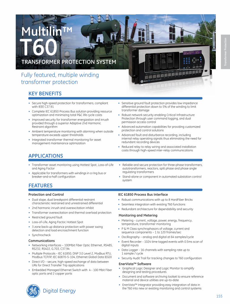
Functional Block Diagram
of different type transformers, can be set to either traditional or adaptive mode. The adaptive mode maximizes dependability on internal faults and ensures security during inrush conditions even with weak second harmonics. It reduces the sensitivity of magnitude comparison by biasing towards security based on angular relationship. Dependability is maintained by applying the restraint signal only for a period of time dependent on the magnitude ratio.
Overexcitation Inhibit
An increase in transformer voltage or decrease in system frequency may result in overexcitation of the transformer. It is often desirable to prevent operation of
the percent differential element in these cases therefore a fifth harmonic inhibit is integrated into the percent differential element to cater for overexcitation conditions resulting from an increased V/Hz ratio.
Unrestrained Differential
An unrestrained differential element is provided for fast tripping on heavy internal faults to limit catastrophic damage to the transformer and minimize risks to the remainder of the power system.
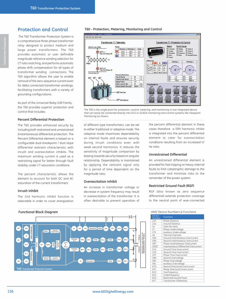
Restricted Ground Fault (RGF)
RGF (also known as zero sequence differential) extends protection coverage to the neutral point of wye-connected
The T60 is the single point for protection, control, metering, and monitoring in one integrated device that can easily be connected directly into DCS or SCADA monitoring and control systems like Viewpoint Monitoring as shown.
ANSI Device Numbers & Functions
T60 - Protection, Metering, Monitoring and Control
Device Number Function21P Phase Distance21G Ground Distance24 Volts Per Hertz27 Phase Undervoltage27X Auxiliary Undervoltage49 Thermal Overload 50G Ground Instantaneous Overcurrent50N Neutral Instantaneous Overcurrent50P Phase Instantaneous Overcurrent50/87 Instantaneous Differential Overcurrent51G Ground Time Overcurrent51N Neutral Time Overcurrent51P Phase Time Overcurrent59N Neutral Overvoltage59P Phase Overvoltage59C Auxiliary Overvoltage67N Neutral Directional Overcurrent67P Phase Directional Overcurrent81O Overfrequency81U Underfrequency87G Restricted Ground Fault87T Transformer Differential
157157
T60 Transformer Protection System
Tran
sfor
mer
Pro
tect
ion
www.GEDigitalEnergy.com
its input signal. Applications could include: overvoltage, overpower, low power factor, temperature differential, and more.
IEC 61850 Process BusThe IEC 61850 Process Bus module is designed to interface with the Multilin HardFiber System, allowing bi-directional IEC 61850 fiber optic communications. The HardFiber System is designed to integrate seamlessly with the existing Universal Relay applications, including protection functions, FlexLogic, metering and communications.
The Multilin HardFiber System offers the following benefits:
• Communicates using open standard IEC 61850 messaging
• Drastically reduces P&C design, installation and testing labor by eliminating individual copper terminations
• Integrates with existing T60’s by replacing traditional CT/VT inputs with IEC 61850 Process Bus module
• Does not introduce new Cyber Security concerns
Visit the HardFiber System product page on the GE Digital Energy web site for more details.
Advanced AutomationThe T60 incorporates advanced automation features including powerful FlexLogic™ programmable logic, communication, and
windings where fault currents may be below the pickup of the main transformer differential elements. The low-impedance RGF protection provided in the T60 uses an optimized adaptive restraint signal that provides security for external fault conditions that may cause CT saturation while still maintaining sensitivity for internal faults.
Distance
Separate high-speed phase and ground distance elements are provided in T60 as a back-up protection. T60 comes with three phase and ground distance quad and mho distance elements. The phase distance elements come with built-in in-zone transformer compensation. The T60 also provides a load encroachment element , which supervises the distance elements under heavy resistive loading conditions.
Overcurrent Functions
T60 provides thermal overload, time and instantaneous overcurrent elements for phase, neutral, ground, phase and neutral directional. All of them can run in parallel with primary differential protection or can be programmed to provide primary protection under conditions when other protections elements are blocked.
User-Definable Protection Functions
Sixteen user-definable protection functions (FlexElements™) can be programmed to respond to any quantity measured or computed by the relay (phase, ground and sequence currents and voltages, power, frequency, power factor, etc.) These elements respond to variations in
SCADA capabilities that far surpass what is found in the average transformer relay. The T60 integrates seamlessly with other UR relays for complete system protection.
FlexLogic™
FlexLogic™ is the powerful UR-platform programming logic engine that provides the ability of creating customized protection and control schemes thereby minimizing the need, and the associated costs, of auxiliary components and wiring.Using FlexLogic™, the T60 can be programmed to provide required tripping logic along with custom scheme logic for line phase comparison (including interlocking with external synchronizers), transfer tripping schemes for remote breakers and dynamic setting group changes.
Scalable HardwareThe T60 is available with a multitude of I/O configurations to suit the most demanding application needs. The expandable modular design allows for easy configuration and future upgrades.
• Multiple CT/VT configurations allow for implementation of many differential schemes, including concurrent split-phase and differential protection
• Types of digital outputs include trip-rated Form-A and Solid State Relay (SSR) mechanically latching, and Form-C outputs
• RTDs and DCmA inputs are available to monitor equipment parameters such as temperature & pressure
Faults close to the neutral point of a wye-connected winding does not generate adequate fault current for differential element to pick up. Restricted Ground Fault protection provides sensitive ground fault detection for low-magnitude fault currents.
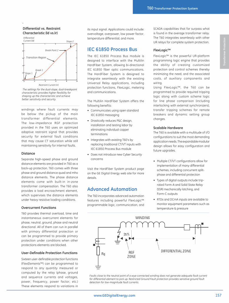
Differential vs. Restraint Characteristic (ld vs.lr)
The settings for the dual-slope, dual-breakpoint characteristic provides higher flexibility for shaping up the characteristic and achieve better sensitivity and security.
Transition Region
Break Point 2
Slope 1Break 1
Differential Current (Id)
Restraint Current (Ir)
Slope 2
158158
T60 Transformer Protection SystemTr
ansf
orm
er P
rote
ctio
n
www.GEDigitalEnergy.com
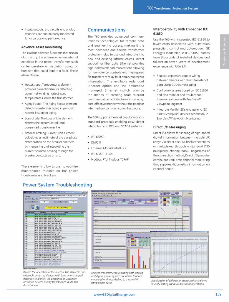
Monitoring and MeteringThe T60 includes high accuracy metering and recording for all AC signals. Voltage, current, and power metering are built into the relay as a standard feature. Current and voltage parameters are available as total RMS magnitude, and as fundamental frequency magnitude and angle. Also, harmonic measurements for voltage and current up to 25th for power quality applications.T60 can monitor, calculate and log hottest-spot temperature, aging factor and lost of life data over a long period. These data
combined with economic analysis, allows criteria to be developed regarding the best time at which to replace a power transformer due to load growth, i.e. to minimize the cost without significantly increasing the risk.
Fault and Disturbance Recording
The advanced disturbance and event recording features within the T60 can significantly reduce the time needed for postmortem analysis of power system events and creation of regulatory reports. Recording functions include:
• Sequence of Event (SOE): 1024 time stamped events
• Oscillography:
64 digital & up to 40 Analog channels
• Data Logger, disturbance recording: 16 channels up to 1 sample / cycle / channel
• Fault Reports: Powerful summary report of pre-fault and fault values
• Extensive breaker info (continuous coil monitor, arcing current, operating time, operation counter for assert management
The very high sampling rates and large amount of storage space available for data recording in the T60 can eliminate the need for installing costly standalone recording equipment.
Temperature Monitoring – RTD Module Option 5C
The T60 RTD option provides 8 programmable RTD inputs per module that are used for temperature monitoring. Each RTD input has 2 operational levels: alarm and trip. The T60 supports RTD trip voting and provides open RTD failure alarming. Alternatively, a remote RTD module “RRTD”, which supports 12 RTD inputs, can also be used with the T60 for temperature monitoring. The RRTD provides cost savings when compared to traditional RTD wiring.
Advanced Device Health Diagnostics
The T60 performs comprehensive device health diagnostic tests during startup and continuously at runtime to test its own major functions and critical hardware. These diagnostic tests monitor for conditions that could impact security and availability of protection, and present device status via SCADA communications and front panel display. Providing continuous monitoring and early detection of possible issues helps improve system uptime.
• Comprehensive device health diagnostic performed during startup
• Monitors the CT/VT input circuitry to validate the integrity of all signals
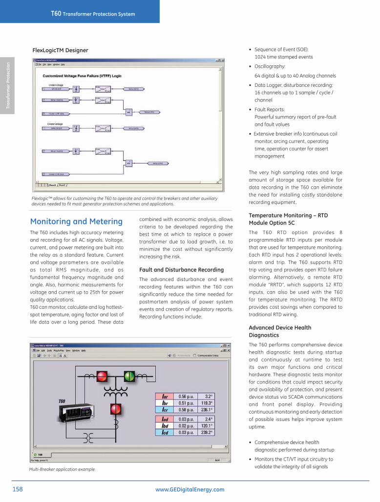
FlexLogicTM Designer
Flexlogic™ allows for customizing the T60 to operate and control the breakers and other auxiliary devices needed to fit most generator protection schemes and applications.
Multi-Breaker application example
159159
T60 Transformer Protection System
Tran
sfor
mer
Pro
tect
ion
www.GEDigitalEnergy.com
• Input, outputs, trip circuits and analog channels are continuously monitored for accuracy and performance
Advance Asset monitoring
The T60 has advance functions that rise an alarm or trip the scheme when an internal condition in the power transformer, such as temperature or insulation aging, or breakers that could lead to a fault . These elements are:
• Hottest-spot Temperature: element provides a mechanism for detecting abnormal winding hottest-spot temperatures inside the transformer.
• Aging Factor: The Aging Factor element detects transformer aging in per-unit normal insulation aging.
• Loss of Life: The Loss of Life element detects the accumulated total consumed transformer life.
• Breaker Arching Current: This element calculates an estimate of the per-phase deterioration on the breaker contacts by measuring and integrating the current squared passing through the breaker contacts as an arc.
These elements allow to user to optimize maintenance routines on the power transformer and breakers.
CommunicationsThe T60 provides advanced commun-ications technologies for remote data and engineering access, making it the most advanced and flexible transformer protection relay to use and integrate into new and existing infrastructures. Direct support for fiber optic Ethernet provides high-bandwidth communications allowing for low-latency controls and high-speed file transfers of relay fault and event record information. The available redundant Ethernet option and the embedded managed Ethernet switch provide the means of creating fault tolerant communication architectures in an easy, cost-effective manner without the need for intermediary communication hardware.
The T60 supports the most popular industry standard protocols enabling easy, direct integration into DCS and SCADA systems.
• IEC 61850
• DNP3.0
• Ethernet Global Data (EGD)
• IEC 60870-5-104
• Modbus RTU, Modbus TCP/IP
Interoperability with Embedded IEC 61850
Use the T60 with integrated IEC 61850 to lower costs associated with substation protection, control and automation. GE Energy’s leadership in IEC 61850 comes from thousands of installed devices and follows on seven years of development experience with UCA 2.0.
• Replace expensive copper wiring between devices with direct transfer of data using GOOSE messaging
• Configure systems based on IEC 61850 and also monitor and troubleshoot them in real-time with EnerVista™ Viewpoint Engineer
• Integrate Multilin IEDs and generic IEC 61850-compliant devices seamlessly in EnerVista™ Viewpoint Monitoring
Direct I/O Messaging
Direct I/O allows for sharing of high-speed digital information between multiple UR relays via direct back-to-back connections or multiplexed through a standard DS0 multiplexer channel bank. Regardless of the connection method, Direct I/O provides continuous real-time channel monitoring that supplies diagnostics information on channel health.
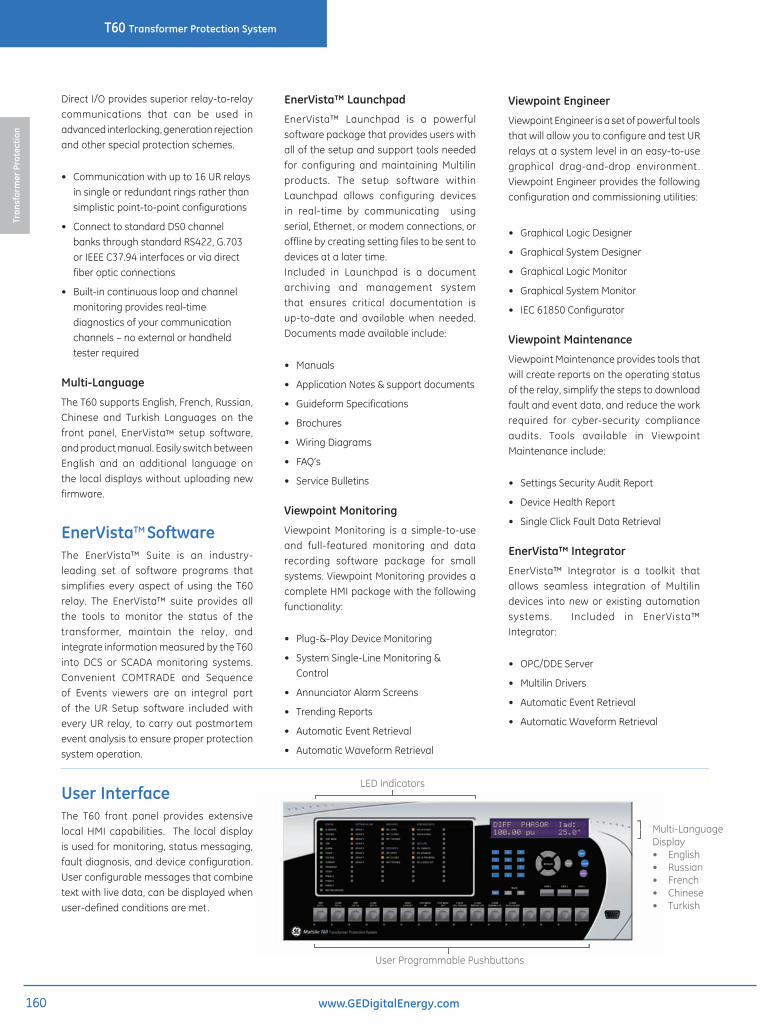
Analyze transformer faults using both analog and digital power system quantities that are measured and recorded up to a rate of 64 samples per cycle.
Record the operation of the internal T60 elements and external connected devices with 1ms time-stamped accuracy to identify the Sequence of Operation of station devices during transformer faults and disturbances.
Power System Troubleshooting
Visualization of differential characteristics allows to verify settings and trouble shoot operations.
160160
T60 Transformer Protection SystemTr
ansf
orm
er P
rote
ctio
n
www.GEDigitalEnergy.com
Direct I/O provides superior relay-to-relay communications that can be used in advanced interlocking, generation rejection and other special protection schemes.
• Communication with up to 16 UR relays in single or redundant rings rather than simplistic point-to-point configurations
• Connect to standard DS0 channel banks through standard RS422, G.703 or IEEE C37.94 interfaces or via direct fiber optic connections
• Built-in continuous loop and channel monitoring provides real-time diagnostics of your communication channels – no external or handheld tester required
Multi-Language
The T60 supports English, French, Russian, Chinese and Turkish Languages on the front panel, EnerVista™ setup software, and product manual. Easily switch between English and an additional language on the local displays without uploading new firmware.
EnerVistaTM SoftwareThe EnerVista™ Suite is an industry-leading set of software programs that simplifies every aspect of using the T60 relay. The EnerVista™ suite provides all the tools to monitor the status of the transformer, maintain the relay, and integrate information measured by the T60 into DCS or SCADA monitoring systems. Convenient COMTRADE and Sequence of Events viewers are an integral part of the UR Setup software included with every UR relay, to carry out postmortem event analysis to ensure proper protection system operation.
EnerVista™ Launchpad
EnerVista™ Launchpad is a powerful software package that provides users with all of the setup and support tools needed for configuring and maintaining Multilin products. The setup software within Launchpad allows configuring devices in real-time by communicating using serial, Ethernet, or modem connections, or offline by creating setting files to be sent to devices at a later time.Included in Launchpad is a document archiving and management system that ensures critical documentation is up-to-date and available when needed. Documents made available include:
• Manuals
• Application Notes & support documents
• Guideform Specifications
• Brochures
• Wiring Diagrams
• FAQ’s
• Service Bulletins
Viewpoint Monitoring
Viewpoint Monitoring is a simple-to-use and full-featured monitoring and data recording software package for small systems. Viewpoint Monitoring provides a complete HMI package with the following functionality:
• Plug-&-Play Device Monitoring
• System Single-Line Monitoring & Control
• Annunciator Alarm Screens
• Trending Reports
• Automatic Event Retrieval
• Automatic Waveform Retrieval
Viewpoint Engineer
Viewpoint Engineer is a set of powerful tools that will allow you to configure and test UR relays at a system level in an easy-to-use graphical drag-and-drop environment . Viewpoint Engineer provides the following configuration and commissioning utilities:
• Graphical Logic Designer
• Graphical System Designer
• Graphical Logic Monitor
• Graphical System Monitor
• IEC 61850 Configurator
Viewpoint Maintenance
Viewpoint Maintenance provides tools that will create reports on the operating status of the relay, simplify the steps to download fault and event data, and reduce the work required for cyber-security compliance audits. Tools available in Viewpoint Maintenance include:
• Settings Security Audit Report
• Device Health Report
• Single Click Fault Data Retrieval
EnerVista™ Integrator
EnerVista™ Integrator is a toolkit that allows seamless integration of Multilin devices into new or existing automation systems. Included in EnerVista™ Integrator:
• OPC/DDE Server
• Multilin Drivers
• Automatic Event Retrieval
• Automatic Waveform Retrieval
User InterfaceThe T60 front panel provides extensive local HMI capabilities. The local display is used for monitoring, status messaging, fault diagnosis, and device configuration. User configurable messages that combine text with live data, can be displayed when user-defined conditions are met.
LED Indicators
Multi-Language Display• English• Russian • French • Chinese• Turkish
User Programmable Pushbuttons
161161
T60 Transformer Protection System
Tran
sfor
mer
Pro
tect
ion
www.GEDigitalEnergy.com
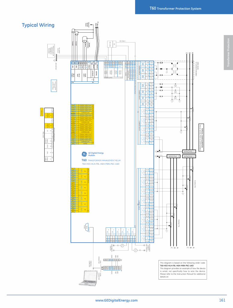
Typical Wiring
T60T60-H03-HLH-F8L-H6H-M8N-P6C-U6D
TC
TC
2
1
3
I
V
15 26 4
6H
I
V
I
V
I
V
I
V
I
V
H8a
H7b
H7a
H8c
H7c
SUR
GE
H8b
CRITIC
AL
FAILU
RE
OU
TPUT
CO
NTR
OL
POW
ERH
I
MED
LO
1
FILTERSU
RG
E
B5a
B3a
B1b
B8a
B6b
B8b
B6a
B3b
B1a
B2b
B5b
minim
um
DC
7c
8c
8b
8a
5c
5a
5b
7b
3c
4b
4a
4c
1c
6a
2b
7a
2a
6b
6c
2c
1a
1b
3a
3b
M
M
M
M
M
M
M
M
M
M
M
M
M
M
M
M
M
M
M
M
M
M
M
M
IA
IB
IC
IG
IA5
IA1
IB5
IC5
IG5
IB1
IC1
IG1
IA
IB
IC
IG
IA5
IA1
IB5
IC5
IG5
IB1
IC1
IG1
AA BB CC
6C
P1
P5
P2
P6
P3
P7
P4
P8
P7a
P1a
P2b
P7c
P1c
P7b
P1b
P8cP8b
P2c
P8a
P2a
P4a
P5b
P4c
P6b
P3bP3a
P6a
P4b
P5c
P5a
P3c
P6c
1
Power
supply
8
CT/V
T
6Inputs/outputs
*
6CT
6Inputs/outputs
*
6
Inputs/outputs
9
CPU
JU
MX
LW
KV
BH
TD
NG
FP
SR
PRO
VIDED
U6a
U8a
U5b
U7b
U5a
U7a
U6c
U8c
U5c
U7c
SURGE
U1a
U8b
U4c
U2c
U3aU3c
U1c
U3b
U1b
U4a
U2a
6D
T60C
OM
PUTER
11
83220764522
CO
NN
ECTO
R
PERSON
AL
CO
MPU
TER
CO
NN
ECTO
R
22
33
44
55
66
77
88
99
TXDRXD
RXDTXD
SGN
DSG
ND
RS-232
DB
-9
(front)
F1c
F4a
F8c
F8a
F3c
F5a
F5c
F7c
F6a
F7a
F6c
F2c
VX
VA
VB
VC
F4c
F1a
F4b
F1b
F2a
F3a
F2b
F3b
VX
VA
VB
VC
IA
IB
IC
IG
IA5
IA1
IB5
IC5
IG5
IB1
IC1
IG1
ABC
F5a
F5c
F7c
F6a
F7a
F6c
VA
VB
VC
VA
VB
VC
GE Digital EnergyMultilin
H3b
H3a
H2c
H3c
H1b
H2b
H4b
H5b
H6b
H1a
H2a
H4a
H5a
H6a
H1c
H4c
H5c
H6c
com
10BaseFL
10BaseFL
10BaseT
D1a
D2a
D4b
D3a
D4a
IRIG-B
Input
IRIG-B
Output
CO
M1
RS485
ALTERN
ATE
NO
RMA
L
Tx2Rx2
Tx1Rx1
BN
C
BN
C
FibreO
ptic*
Remote
Device
Shielded
Co-axial
Co-axial
com
10BaseFL
10BaseFL
10BaseT
D1a
D2a
D4b
D3a
D4a
IRIG-B
Input
IRIG-B
Output
CO
M1
RS485
ALTERN
ATE
NO
RMA
L
Tx2Rx2
Tx1Rx1
BN
C
BN
C
FibreO
ptic*
Remote
Device
Shielded
Co-axial
Co-axial
This diagram is based on the following order code: T60-H03-HLH-F8L-H6H-M8N-P6C-U6DThis diagram provides an example of how the device is wired, not specifically how to wire the device. Please refer to the Instruction Manual for additional details on

162162
T60 Transformer Protection SystemTr
ansf
orm
er P
rote
ctio
n
www.GEDigitalEnergy.com
T60 - * 00 - H * * - F ** - H ** - M ** -P ** - U ** - W/X ** For Full Sized Horizontal MountBase Unit T60 Base UnitCPU E RS485 + RS485 (IEC 61850 option not available) G RS485 + Multi-mode ST 10BaseF H RS485 + Mutli-mode ST Redundant 10BaseF J RS485 + Multi-mode ST 100BaseFX K RS485 + Multi-mode ST Redundant 100BaseFX N RS485 + 10/100 BaseT S RS485 + 6 port, 100 Mbps, Managed Ethernet SwitchSoftware Options 00 No Software Options 01 Ethernet Global Data (EGD) 03 IEC 61850 04 Ethernet Global Data (EGD) + IEC 61850 06 PMU 07 IEC 61850 + PMU 10 Synchrocheck 11 Synchrocheck + IEC 61850 20 5 windings (No Breaker Failure) 21 5 windings (No Breaker Failure) + EGD 22 5 windings (No Breaker Failure) + IEC 61850 23 5 windings (No Breaker Failure) + EGD + IEC 61850 33 PMU + Synchrocheck 34 PMU + IEC 61850 + SynchrocheckMount / Coating H Horizontal (19" rack) - Standard A Horizontal (19" rack) - Harsh Chemical Environment Option V Vertical (3/4 size) - Standard B Vertical (3/4 size) - Harsh Chemical Environment OptionUser Interface K Enhanced English Front Panel L Enhanced English Front Panel with User-Programmable Pushbuttons M Enhanced French Front Panel N Enhanced French Front Panel with User-Programmable Pushbuttons Q Enhanced Russian Front Panel T Enhanced Russian Front Panel with User-Programmable Pushbuttons U Enhanced Chinese Front Panel V Enhanced Chinese Front Panel with User-Programmable Pushbuttons F Vertical Front Panel with English display W Enhanced Turkish Front Panel Y Enhanced Turkish Front Panel with User-Programmable PushbuttonsPower Supply H 125 / 250 V AC/DC H RH 125/250 V AC/DC with redundant 125/250 V AC/DC L 24 - 48 V (DC only)CT/VT DSP 8L 8L Standard 4CT/4VT w/ enhanced diagnostics 8M 8M Sensitive Ground 4CT/4VT w/ enhanced diagnostics 8N 8N Standard 8CT w/ enhanced diagnostics 8R 8R Sensitive Ground 8CT w/ enhanced diagnosticsIEC 61850 Process Bus 81 8 Port IEC 61850 Process Bus ModuleDigital I/O XX XX XX XX XX XX No Module 4A 4A 4A 4A 4A 4A 4 Solid State (No Monitoring) MOSFET Outputs 4C 4C 4C 4C 4C 4C 4 Solid State (Current w/opt Voltage) MOSFET Outputs 4D 4D 4D 4D 4D 4D 16 Digital Inputs with Auto-Burnish 4L 4L 4L 4L 4L 4L 14 Form-A (No Monitoring) Latchable Outputs 67 67 67 67 67 67 8 Form-A (No Monitoring) Outputs 6C 6C 6C 6C 6C 6C 8 Form-C Outputs 6D 6D 6D 6D 6D 6D 16 Digital Inputs 6E 6E 6E 6E 6E 6E 4 Form-C Outputs, 8 Digital Inputs 6F 6F 6F 6F 6F 6F 8 Fast Form-C Outputs 6K 6K 6K 6K 6K 6K 4 Form-C & 4 Fast Form-C Outputs 6L 6L 6L 6L 6L 6L 2 Form-A (Current w/ opt Voltage) & 2 Form-C Outputs, 8 Digital Inputs 6M 6M 6M 6M 6M 6M 2 Form-A (Current w/ opt Voltage) & 4 Form-C Outputs, 4 Digital Inputs 6N 6N 6N 6N 6N 6N 4 Form-A (Current w/ opt Voltage) Outputs, 8 Digital Inputs 6P 6P 6P 6P 6P 6P 6 Form-A (Current w/ opt Voltage) Outputs, 4 Digital Inputs 6R 6R 6R 6R 6R 6R 2 Form-A (No Monitoring) & 2 Form-C Outputs, 8 Digital Inputs 6S 6S 6S 6S 6S 6S 2 Form-A (No Monitoring) & 4 Form-C Outputs, 4 Digital Inputs 6T 6T 6T 6T 6T 6T 4 Form-A (No Monitoring) Outputs, 8 Digital Inputs 6U 6U 6U 6U 6U 6U 6 Form-A (No Monitoring) Outputs, 4 Digital Inputs 6V 6V 6V 6V 6V 6V 2 Form-A (Cur w/ opt Volt) 1 Form-C Output, 2 Latching Outputs, 8 Digital InputsTransducer I/O 5A 5A 5A 5A 5A 5A 4 dcmA Inputs, 4 dcmA Outputs 5C 5C 5C 5C 5C 5C 8 RTD Inputs 5E 5E 5E 5E 5E 5E 4 dcmA Inputs, 4 RTD Inputs 5F 5F 5F 5F 5F 5F 8 dcmA InputsInter-Relay Communications 7A 820 nm, multi-mode, LED, 1 Channel 7B 1300 nm, multi-mode, LED, 1 Channel 7C 1300 nm, single-mode, ELED, 1 Channel 7H 820 nm, multi-mode, LED, 2 Channels 7I 1300 nm, multi-mode, LED, 2 Channels 7J 1300 nm, single-mode, ELED, 2 Channels 7S G.703, 2 Channels 7W RS422, 2 Channels 77 IEEE C37.94, 820 nm, multimode, LED, 2 Channel 2B C37.94SM, 1300nm Singlemode, ELED, 2 Channel Single mode 2S 6 port, 100 Mbps, Managed Ethernet Switch, HI (125/250V AC/DC) 2T 6 port, 100 Mbps, Managed Ethernet Switch, LO (24-48 Vdc)
• UR Applications I Learning CD TRCD-URA1-C-S-1
• Multilink Ethernet Switch ML2400-F-HI-HI-A2-A2-A6-G1
• Viewpoint Engineer VPE-1
• Viewpoint Maintenance VPM-1
• Viewpoint Monitoring IEC 61850 VP-1-61850
Accessories for the T60 • View Guideform specifications
• Download the instruction manual
• Review applications Notes and support documents
• Buy a T60 online
• View the UR Family brochure
Visit www.GEMultilin.com/T60 to:
110927-v6
Ordering
Ordering Notes:1 - For vertical mounting order codes, please refer to: http://pm.geindustrial.com/transformer.asp 2 - To view the latest options available for the T60, or to order the UR Classic Front Panel, please visit our online store for more details.