Embed Size (px)
Citation preview
IEEE SENSORS JOURNAL, VOL. 11, NO. 3, MARCH 2011 1
Lock-in Time-of-Flight (ToF) Cameras: A SurveySergi Foix, Guillem Alenya and Carme Torras
Abstract—This paper reviews the state-of-the art in the fieldof lock-in ToF cameras, their advantages, their limitations, theexisting calibration methods, and the way they are being used,sometimes in combination with other sensors. Even though lock-in ToF cameras provide neither higher resolution nor largerambiguity-free range compared to other range map estimationsystems, advantages such as registered depth and intensitydata ata high frame rate, compact design, low weight and reduced powerconsumption have motivated their increasing usage in severalresearch areas, such as computer graphics, machine vision androbotics.
Index Terms—Lock-in, time-of-flight, calibration.
I. I NTRODUCTION
T OF camera is a relatively new type of sensor that delivers3-dimensional imaging at a high frame rate, simulta-
neously providing intensity data and range information forevery pixel. Despite the number of pixels in the images isstill small (i.e 176×144 in Swissranger SR3000 and SR4000cameras, and 204×204 in PMD CamCube camera) and noisein the depth values can not yet be completely removed aftercalibration, ToF imaging is rapidly showing a great potentialin numerous scientific domains.
Due to continuous progress in microelectronics, micro op-tics and micro technology, the development of ToF camerashas been possible over the last decade. They outperform pasttechnologies at the still difficult and slow task of depth-intensity image matching. Further efforts are being devotedto the optimisation of the cameras themselves. More compactand lighter cameras with better signal-to-noise ratio are beingdeveloped, and work continues in order to improve present-dayproducts. New camera models have recently appeared, such asPMD CamCube and Swissranger 4K, and impressive resultsare expected once researchers start to work extensively withthese new models.
Depth-intensity pixel-associated images at a high framerate without need of mobile components, combined withother technical advantages such as robustness to illuminationchanges and low weight, make it foreseeable that ToF cameraswill replace previous solutions, or alternatively complementother technologies, in many areas of application.
Thus, this paper tries to give a comprehensive overviewof the state-of-the-art for the off-the-shelf, most widelyusedToF cameras, mainly those relying on demodulation lock-inpixels, describing not only their principles and advantages,
This work has been partially supported by the Spanish Ministry of Scienceand Innovation under project DPI2008-06022, the MIPRCV Consolider In-genio 2010 project, and the EU PACO PLUS project FP6-2004-IST-4-27657.S. Foix and G. Alenya are supported by PhD and postdoctoral fellowships,respectively, from CSIC’s JAE program.
The authors are with the Institut de Robotica i Informatica Industrial, CSIC-UPC, Llorens i Artigas 4-6, 08028 Barcelona, Spain (e-mails: sfoix, galenya,[email protected]).
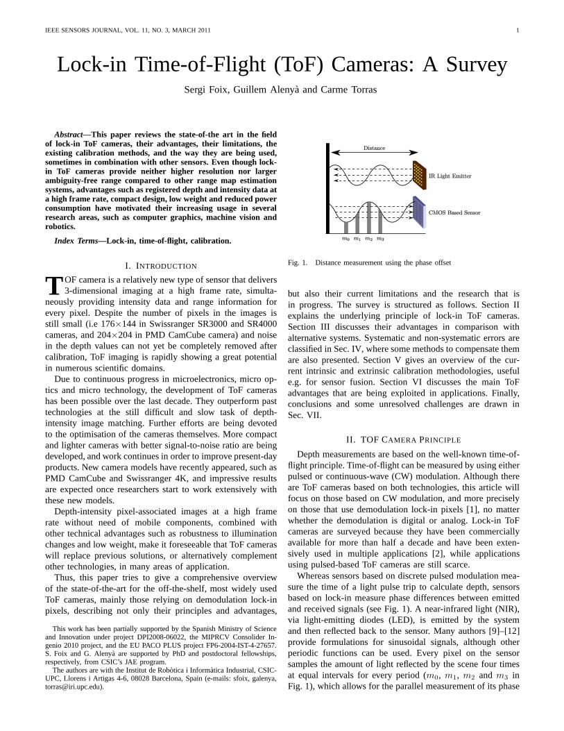
Fig. 1. Distance measurement using the phase offset
but also their current limitations and the research that isin progress. The survey is structured as follows. Section IIexplains the underlying principle of lock-in ToF cameras.Section III discusses their advantages in comparison withalternative systems. Systematic and non-systematic errors areclassified in Sec. IV, where some methods to compensate themare also presented. Section V gives an overview of the cur-rent intrinsic and extrinsic calibration methodologies, usefule.g. for sensor fusion. Section VI discusses the main ToFadvantages that are being exploited in applications. Finally,conclusions and some unresolved challenges are drawn inSec. VII.
II. TOF CAMERA PRINCIPLE
Depth measurements are based on the well-known time-of-flight principle. Time-of-flight can be measured by using eitherpulsed or continuous-wave (CW) modulation. Although thereare ToF cameras based on both technologies, this article willfocus on those based on CW modulation, and more preciselyon those that use demodulation lock-in pixels [1], no matterwhether the demodulation is digital or analog. Lock-in ToFcameras are surveyed because they have been commerciallyavailable for more than half a decade and have been exten-sively used in multiple applications [2], while applicationsusing pulsed-based ToF cameras are still scarce.
Whereas sensors based on discrete pulsed modulation mea-sure the time of a light pulse trip to calculate depth, sensorsbased on lock-in measure phase differences between emittedand received signals (see Fig. 1). A near-infrared light (NIR),via light-emitting diodes (LED), is emitted by the systemand then reflected back to the sensor. Many authors [9]–[12]provide formulations for sinusoidal signals, although otherperiodic functions can be used. Every pixel on the sensorsamples the amount of light reflected by the scene four timesat equal intervals for every period (m0, m1, m2 andm3 inFig. 1), which allows for the parallel measurement of its phase
IEEE SENSORS JOURNAL, VOL. 11, NO. 3, MARCH 2011 2
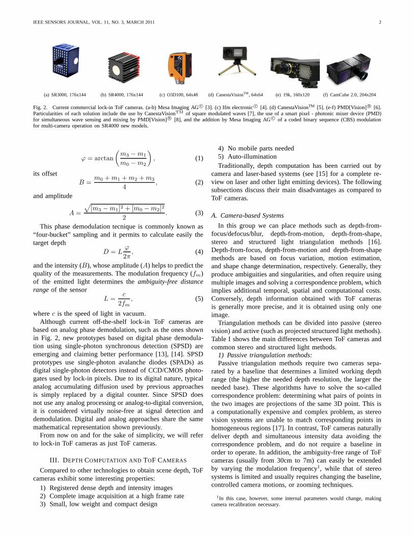
(a) SR3000, 176x144 (b) SR4000, 176x144 (c) O3D100, 64x48 (d) CanestaVisionTM , 64x64 (e) 19k, 160x120 (f) CamCube 2.0, 204x204
Fig. 2. Current commercial lock-in ToF cameras. (a-b) Mesa Imaging AGc© [3]. (c) Ifm electronicc© [4]. (d) CanestaVisionTM [5]. (e-f) PMD[Vision] R© [6].Particularities of each solution include the use by CanestaVisionTM of square modulated waves [7], the use of a smart pixel - photonic mixer device (PMD)for simultaneous wave sensing and mixing by PMD[Vision]R© [8], and the addition by Mesa Imaging AGc© of a coded binary sequence (CBS) modulationfor multi-camera operation on SR4000 new models.
ϕ = arctan
(
m3 −m1
m0 −m2
)
, (1)
its offsetB =
m0 +m1 +m2 +m3
4, (2)
and amplitude
A =
√
[m3 −m1]2 + [m0 −m2]2
2. (3)
This phase demodulation tecnique is commonly known as“four-bucket” sampling and it permits to calculate easily thetarget depth
D = Lϕ
2π, (4)
and the intensity (B), whose amplitude (A) helps to predict thequality of the measurements. The modulation frequency (fm)of the emitted light determines theambiguity-free distancerange of the sensor
L =c
2fm, (5)
wherec is the speed of light in vacuum.Although current off-the-shelf lock-in ToF cameras are
based on analog phase demodulation, such as the ones shownin Fig. 2, new prototypes based on digital phase demodula-tion using single-photon synchronous detection (SPSD) areemerging and claiming better performance [13], [14]. SPSDprototypes use single-photon avalanche diodes (SPADs) asdigital single-photon detectors instead of CCD/CMOS photo-gates used by lock-in pixels. Due to its digital nature, typicalanalog accumulating diffusion used by previous approachesis simply replaced by a digital counter. Since SPSD doesnot use any analog processing or analog-to-digital conversion,it is considered virtually noise-free at signal detection anddemodulation. Digital and analog approaches share the samemathematical representation shown previously.
From now on and for the sake of simplicity, we will referto lock-in ToF cameras as just ToF cameras.
III. D EPTH COMPUTATION AND TOF CAMERAS
Compared to other technologies to obtain scene depth, ToFcameras exhibit some interesting properties:
1) Registered dense depth and intensity images2) Complete image acquisition at a high frame rate3) Small, low weight and compact design
4) No mobile parts needed5) Auto-illuminationTraditionally, depth computation has been carried out by
camera and laser-based systems (see [15] for a complete re-view on laser and other light emitting devices). The followingsubsections discuss their main disadvantages as compared toToF cameras.
A. Camera-based Systems
In this group we can place methods such as depth-from-focus/defocus/blur, depth-from-motion, depth-from-shape,stereo and structured light triangulation methods [16].Depth-from-focus, depth-from-motion and depth-from-shapemethods are based on focus variation, motion estimation,and shape change determination, respectively. Generally,theyproduce ambiguities and singularities, and often require usingmultiple images and solving a correspondence problem, whichimplies additional temporal, spatial and computational costs.Conversely, depth information obtained with ToF camerasis generally more precise, and it is obtained using only oneimage.
Triangulation methods can be divided into passive (stereovision) and active (such as projected structured light methods).Table I shows the main differences between ToF cameras andcommon stereo and structured light methods.
1) Passive triangulation methods:Passive triangulation methods require two cameras sepa-
rated by a baseline that determines a limited working depthrange (the higher the needed depth resolution, the larger theneeded base). These algorithms have to solve the so-calledcorrespondence problem: determining what pairs of points inthe two images are projections of the same 3D point. This isa computationally expensive and complex problem, as stereovision systems are unable to match corresponding points inhomogeneous regions [17]. In contrast, ToF cameras naturallydeliver depth and simultaneous intensity data avoiding thecorrespondence problem, and do not require a baseline inorder to operate. In addition, the ambiguity-free range of ToFcameras (usually from 30cm to 7m) can easily be extendedby varying the modulation frequency1, while that of stereosystems is limited and usually requires changing the baseline,controlled camera motions, or zooming techniques.
1In this case, however, some internal parameters would change, makingcamera recalibration necessary.
IEEE SENSORS JOURNAL, VOL. 11, NO. 3, MARCH 2011 3
TABLE ITOF CAMERA VS. TRIANGULATION METHODS.
Differences ToF cameras Stereo vision Structured lightCorrespondence
No Yes YesproblemExtrinsic No, Yes Yes
calibration when used aloneAuto Yes No Yes
illuminationUntextured Good Bad Good
surfaces performance performance performance
Depth range 0.3 ÷ 7.5 m.Base-line Light-powerdependent dependent
Image resolution Up to 204x204 High resolution.Camera dependent
Frame rate Up to 25 fps. Typically 25 fps.Camera dependent
2) Active triangulation methods:Contrarily to the preceding methods, active triangulation
ones require only one camera together with a structured lightemitter that projects one line or a complete set of patterns.Disadvantages here, in comparison with ToF cameras, includepartial occlusions that involve missing depth measurements, aneed of highly powered and focused light, occasional scanningof the light through the scene which results in low framerates, and a very controlled light environment that leads toa big restriction in domestic or outdoor robotics applications.Recent approaches [18] solve the partial occlusions problemand the low frame rate by projecting the structured light alongthe optical path of the camera, and using pattern defocus as adepth estimation technique.
B. Laser-based Systems
Laser-based systems provide very precise sliced 3D mea-surements. Albeit they have been successfully applied tosolve Simultaneous Localization and Mapping (SLAM) prob-lems [19], difficulties in collision avoidance have been re-ported due to their 3D reduced field of view [11]. The commonsolution has been mounting the sensor on a pan-and-tilt unit.This implies row by row sampling, and makes this solutioninappropriate for real-time, dynamic scenes, as opposed toToFcameras. Although high depth range, accuracy and reliabilityare advantageous in these systems, they are voluminous, heavy,increase the power consumption, and add additional movingparts. ToF cameras, on the contrary, are compact and portable,they do not require the control of mechanical moving parts,thus reducing power consumption, and they do not need rowby row sampling, thus reducing image acquisition time.
In sum, ToF cameras have evolved rapidly during thelast two decades and, despite their low resolution and lowambiguity-free range, they are already showing great potentialin many applications where not very precise but fast 3Dimage range data acquisition is needed, such as obstacleavoidance [11], [20] , pose estimation [21], [22] , coarse 3Dobject reconstruction [23], [24] , human body parts recognitionand tracking [25]–[27] among others (see [2] for a detailed
1 2 3 4 5
−0.1
−0.05
0
0.05
0.1
0.15Wiggling effect at multiple ITs
Real distance in meters
Offs
et d
ista
nce
in m
eter
s
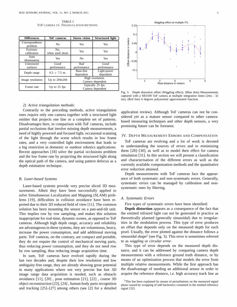
Fig. 3. Depth distortion offset (Wiggling effect). (Blue dots) Measurementscaptured with a SR3100 ToF camera at multiple integration times (2ms - 32ms). (Red line) 6 degrees polynomial approximated function.
application review). Although ToF cameras can not be con-sidered yet as a mature sensor compared to other camera-based measuring techniques and other depth sensors, a verypromising future can be foreseen.
IV. D EPTH MEASUREMENTERRORS ANDCOMPENSATION
ToF cameras are evolving and a lot of work is devotedto understanding the sources of errors and to minimizingthem [28]–[30], as well as to model their effect for camerasimulation [31]. In this section we will present a classificationand characterisation of the different errors as well as thecurrently available compensation methods and the quantitativeerror reduction attained.
Depth measurements with ToF cameras face the appear-ance of both systematic and non-systematic errors. Generally,systematic errors can be managed by calibration and non-systematic ones by filtering.
A. Systematic Errors
Five types of systematic errors have been identified:Depth distortion appears as a consequence of the fact that
the emitted infrared light can not be generated in practice astheoretically planned (generally sinusoidal) due to irregular-ities in the modulation process. This type of error producesan offset that depends only on the measured depth for eachpixel. Usually, the error plotted against the distance follows asinusoidal shape2 (see Fig. 3). This error is sometimes referredto aswiggling or circular error.
This type of error depends on the measured depth dis-tance, and it can be addressed by comparing camera depthmeasurements with a reference ground truth distance, or bymeans of an optimisation process that models the error frommultiple relative measurements. While the first approach hasthe disadvantage of needing an additional sensor in order toacquire the reference distance, i.e. high accuracy track line as
2This has been explained by means of perturbations on the measured signalphase caused by wrapping of odd harmonics contained in the emitted referencesignal [32].
IEEE SENSORS JOURNAL, VOL. 11, NO. 3, MARCH 2011 4
−0.5 0 0.50.8
0.85
0.9
0.95
1
1.05
1.1
IT: 2ms
X(m)
Z(m
)
(a) 2ms integration time
−0.5 0 0.50.8
0.85
0.9
0.95
1
1.05
1.1
IT: 4ms
X(m)
Z(m
)
(b) 4ms integration time
−0.5 0 0.50.8
0.85
0.9
0.95
1
1.05
1.1
IT: 8ms
X(m)
Z(m
)
(c) 8ms integration time
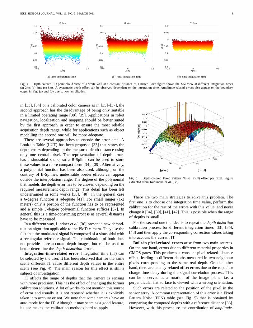
Fig. 4. Depth-colored 3D point cloud view of a white wall at a constant distance of 1 meter. Each figure shows the X/Z view at different integration times(a) 2ms (b) 4ms (c) 8ms. A systematic depth offset can be observed dependent on the integration time. Amplitude-related errors also appear on the boundaryedges in Fig. (a) and (b) due to low amplitudes.
in [33], [34] or a calibrated color camera as in [35]–[37], thesecond approach has the disadvantage of being only suitablein a limited operating range [38], [39]. Applications in robotnavigation, localization and mapping should be better suitedby the first approach in order to ensure the most reliableacquisition depth range, while for applications such as objectmodelling the second one will be more adequate.
There are several approaches to encode the error data. ALook-up Table (LUT) has been proposed [33] that stores thedepth errors depending on the measured depth distance usingonly one central pixel. The representation of depth errorshas a sinusoidal shape, so a B-Spline can be used to storethese values in a more compact form [34], [39]. Alternatively,a polynomial function has been also used, although, on thecontrary of B-Splines, undesirable border effects can appearoutside the interpolation range. The degree of the polynomialthat models the depth error has to be chosen depending on therequired measurement depth range. This detail has been leftundetermined in some works [38], [40]. In the general casea 6-degree function is adequate [41]. For small ranges (1-2meters) only a portion of the function has to be representedand a simple 3-degree polynomial function suffices [37]. Ingeneral this is a time-consuming process as several distanceshave to be measured.
In a different way, Lindneret al. [36] present a new demod-ulation algorithm applicable to the PMD camera. They use thefact that the modulated signal is composed of a sinusoidal witha rectangular reference signal. The combination of both doesnot provide more accurate depth images, but can be used tobetter determine thedepth distortion errors.
Integration-time-related error . Integration time (IT) canbe selected by the user. It has been observed that for the samescene different IT cause different depth values in the entirescene (see Fig. 4). The main reason for this effect is still asubject of investigation.
IT affects the range of depths that the camera is sensingwith more precision. This has the effect of changing the formercalibration solutions. A lot of works do not mention this sourceof error and usually it is not reported whether it is explicitlytaken into account or not. We note that some cameras have anauto mode for the IT. Although it may seem as a good feature,its use makes the calibration methods hard to apply.
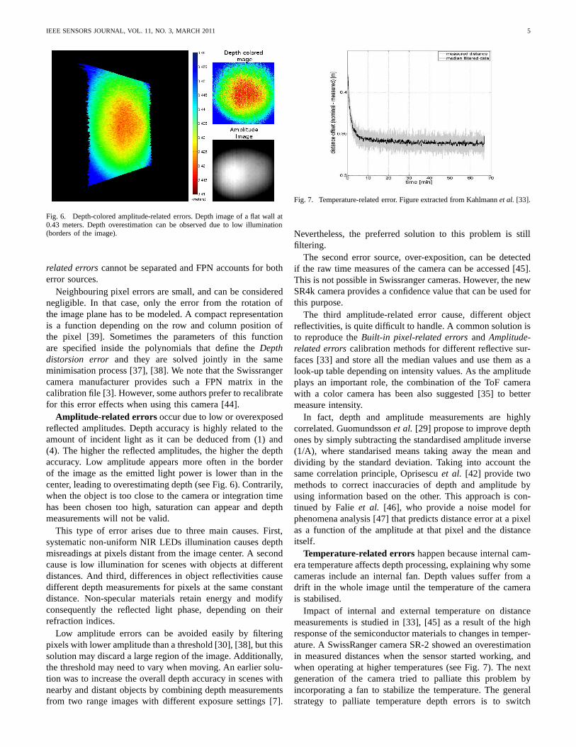
Fig. 5. Depth-colored Fixed Pattern Noise (FPN) offset per pixel. Figureextracted from Kahlmannet al. [33].
There are two main strategies to solve this problem. Thefirst one is to choose one integration time value, perform thecalibration for the rest of the errors with this value, and neverchange it [34], [39], [41], [42]. This is possible when the rangeof depths is small.
For the second one the idea is to repeat thedepth distortioncalibration process for different integration times [33],[35],[43] and then apply the corresponding correction values takinginto account the current IT.
Built-in pixel-related errors arise from two main sources.On the one hand, errors due to different material propertiesinCMOS-gates. This produces a constant pixel-related distanceoffset, leading to different depths measured in two neighbourpixels corresponding to the same real depth. On the otherhand, there are latency-related offset errors due to the capacitorcharge time delay during the signal correlation process. Thiscan be observed as a rotation of the image plane, i.e. aperpendicular flat surface is viewed with a wrong orientation.
Such errors are related to the position of the pixel in thesensor array. A common representation of this error is a FixedPattern Noise (FPN) table (see Fig. 5) that is obtained bycomparing the computed depths with a reference distance [33].However, with this procedure the contribution ofamplitude-
IEEE SENSORS JOURNAL, VOL. 11, NO. 3, MARCH 2011 5
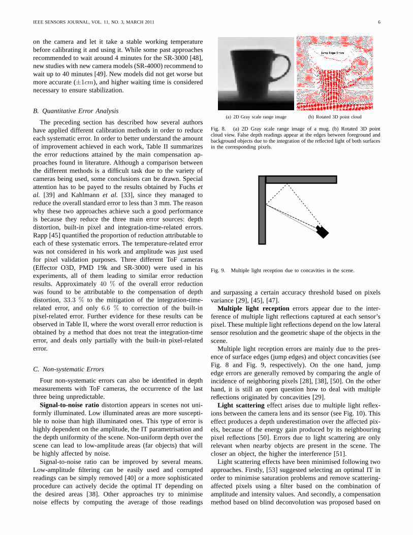
Fig. 6. Depth-colored amplitude-related errors. Depth image of a flat wall at0.43 meters. Depth overestimation can be observed due to lowillumination(borders of the image).
related errors cannot be separated and FPN accounts for botherror sources.
Neighbouring pixel errors are small, and can be considerednegligible. In that case, only the error from the rotation ofthe image plane has to be modeled. A compact representationis a function depending on the row and column position ofthe pixel [39]. Sometimes the parameters of this functionare specified inside the polynomials that define theDepthdistorsion error and they are solved jointly in the sameminimisation process [37], [38]. We note that the Swissrangercamera manufacturer provides such a FPN matrix in thecalibration file [3]. However, some authors prefer to recalibratefor this error effects when using this camera [44].
Amplitude-related errors occur due to low or overexposedreflected amplitudes. Depth accuracy is highly related to theamount of incident light as it can be deduced from (1) and(4). The higher the reflected amplitudes, the higher the depthaccuracy. Low amplitude appears more often in the borderof the image as the emitted light power is lower than in thecenter, leading to overestimating depth (see Fig. 6). Contrarily,when the object is too close to the camera or integration timehas been chosen too high, saturation can appear and depthmeasurements will not be valid.
This type of error arises due to three main causes. First,systematic non-uniform NIR LEDs illumination causes depthmisreadings at pixels distant from the image center. A secondcause is low illumination for scenes with objects at differentdistances. And third, differences in object reflectivitiescausedifferent depth measurements for pixels at the same constantdistance. Non-specular materials retain energy and modifyconsequently the reflected light phase, depending on theirrefraction indices.
Low amplitude errors can be avoided easily by filteringpixels with lower amplitude than a threshold [30], [38], butthissolution may discard a large region of the image. Additionally,the threshold may need to vary when moving. An earlier solu-tion was to increase the overall depth accuracy in scenes withnearby and distant objects by combining depth measurementsfrom two range images with different exposure settings [7].
Fig. 7. Temperature-related error. Figure extracted from Kahlmannet al. [33].
Nevertheless, the preferred solution to this problem is stillfiltering.
The second error source, over-exposition, can be detectedif the raw time measures of the camera can be accessed [45].This is not possible in Swissranger cameras. However, the newSR4k camera provides a confidence value that can be used forthis purpose.
The third amplitude-related error cause, different objectreflectivities, is quite difficult to handle. A common solution isto reproduce theBuilt-in pixel-related errors and Amplitude-related errors calibration methods for different reflective sur-faces [33] and store all the median values and use them as alook-up table depending on intensity values. As the amplitudeplays an important role, the combination of the ToF camerawith a color camera has been also suggested [35] to bettermeasure intensity.
In fact, depth and amplitude measurements are highlycorrelated. Guomundssonet al. [29] propose to improve depthones by simply subtracting the standardised amplitude inverse(1/A), where standarised means taking away the mean anddividing by the standard deviation. Taking into account thesame correlation principle, Oprisescuet al. [42] provide twomethods to correct inaccuracies of depth and amplitude byusing information based on the other. This approach is con-tinued by Falieet al. [46], who provide a noise model forphenomena analysis [47] that predicts distance error at a pixelas a function of the amplitude at that pixel and the distanceitself.
Temperature-related errors happen because internal cam-era temperature affects depth processing, explaining why somecameras include an internal fan. Depth values suffer from adrift in the whole image until the temperature of the camerais stabilised.
Impact of internal and external temperature on distancemeasurements is studied in [33], [45] as a result of the highresponse of the semiconductor materials to changes in temper-ature. A SwissRanger camera SR-2 showed an overestimationin measured distances when the sensor started working, andwhen operating at higher temperatures (see Fig. 7). The nextgeneration of the camera tried to palliate this problem byincorporating a fan to stabilize the temperature. The generalstrategy to palliate temperature depth errors is to switch
IEEE SENSORS JOURNAL, VOL. 11, NO. 3, MARCH 2011 6
on the camera and let it take a stable working temperaturebefore calibrating it and using it. While some past approachesrecommended to wait around 4 minutes for the SR-3000 [48],new studies with new camera models (SR-4000) recommend towait up to 40 minutes [49]. New models did not get worse butmore accurate (±1cm), and higher waiting time is considerednecessary to ensure stabilization.
B. Quantitative Error Analysis
The preceding section has described how several authorshave applied different calibration methods in order to reduceeach systematic error. In order to better understand the amountof improvement achieved in each work, Table II summarizesthe error reductions attained by the main compensation ap-proaches found in literature. Although a comparison betweenthe different methods is a difficult task due to the variety ofcameras being used, some conclusions can be drawn. Specialattention has to be payed to the results obtained by Fuchsetal. [39] and Kahlmannet al. [33], since they managed toreduce the overall standard error to less than 3 mm. The reasonwhy these two approaches achieve such a good performanceis because they reduce the three main error sources: depthdistortion, built-in pixel and integration-time-relatederrors.Rapp [45] quantified the proportion of reduction attributable toeach of these systematic errors. The temperature-related errorwas not considered in his work and amplitude was just usedfor pixel validation purposes. Three different ToF cameras(Effector O3D, PMD 19k and SR-3000) were used in hisexperiments, all of them leading to similar error reductionresults. Approximately40 % of the overall error reductionwas found to be attributable to the compensation of depthdistortion, 33.3 % to the mitigation of the integration-time-related error, and only6.6 % to correction of the built-inpixel-related error. Further evidence for these results can beobserved in Table II, where the worst overall error reduction isobtained by a method that does not treat the integration-timeerror, and deals only partially with the built-in pixel-relatederror.
C. Non-systematic Errors
Four non-systematic errors can also be identified in depthmeasurements with ToF cameras, the occurrence of the lastthree being unpredictable.
Signal-to-noise ratio distortion appears in scenes not uni-formly illuminated. Low illuminated areas are more suscepti-ble to noise than high illuminated ones. This type of error ishighly dependent on the amplitude, the IT parametrisation andthe depth uniformity of the scene. Non-uniform depth over thescene can lead to low-amplitude areas (far objects) that willbe highly affected by noise.
Signal-to-noise ratio can be improved by several means.Low-amplitude filtering can be easily used and corruptedreadings can be simply removed [40] or a more sophisticatedprocedure can actively decide the optimal IT depending onthe desired areas [38]. Other approaches try to minimisenoise effects by computing the average of those readings
(a) 2D Gray scale range image (b) Rotated 3D point cloud
Fig. 8. (a) 2D Gray scale range image of a mug. (b) Rotated 3D pointcloud view. False depth readings appear at the edges betweenforeground andbackground objects due to the integration of the reflected light of both surfacesin the corresponding pixels.
Fig. 9. Multiple light reception due to concavities in the scene.
and surpassing a certain accuracy threshold based on pixelsvariance [29], [45], [47].
Multiple light reception errors appear due to the inter-ference of multiple light reflections captured at each sensor’spixel. These multiple light reflections depend on the low lateralsensor resolution and the geometric shape of the objects in thescene.
Multiple light reception errors are mainly due to the pres-ence of surface edges (jump edges) and object concavities (seeFig. 8 and Fig. 9, respectively). On the one hand, jumpedge errors are generally removed by comparing the angle ofincidence of neighboring pixels [28], [38], [50]. On the otherhand, it is still an open question how to deal with multiplereflections originated by concavities [29].
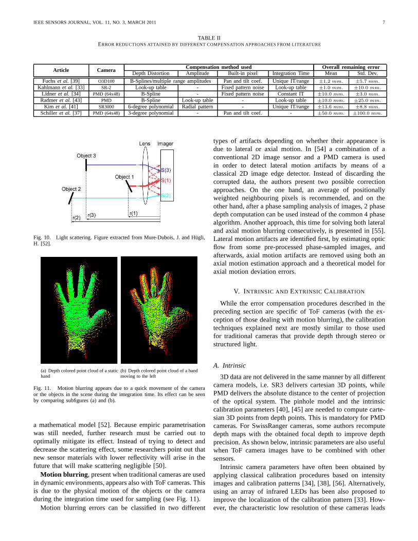
Light scattering effect arises due to multiple light reflex-ions between the camera lens and its sensor (see Fig. 10). Thiseffect produces a depth underestimation over the affected pix-els, because of the energy gain produced by its neighbouringpixel reflections [50]. Errors due to light scattering are onlyrelevant when nearby objects are present in the scene. Thecloser an object, the higher the interference [51].
Light scattering effects have been minimised following twoapproaches. Firstly, [53] suggested selecting an optimal IT inorder to minimise saturation problems and remove scattering-affected pixels using a filter based on the combination ofamplitude and intensity values. And secondly, a compensationmethod based on blind deconvolution was proposed based on
IEEE SENSORS JOURNAL, VOL. 11, NO. 3, MARCH 2011 7
TABLE IIERROR REDUCTIONS ATTAINED BY DIFFERENT COMPENSATION APPROACHES FROM LITERATURE
Article Camera Compensation method used Overall remaining errorDepth Distortion Amplitude Built-in pixel Integration Time Mean Std. Dev.
Fuchset al. [39] O3D100 B-Splines/multiple range amplitudes Pan and tilt coef. Unique IT/range ±1.2 mm. ±5.7 mm.
Kahlmannet al. [33] SR-2 Look-up table - Fixed pattern noise Look-up table ±1.0 mm. ±10.0 mm.
Lidner et al. [34] PMD (64x48) B-Spline - Fixed pattern noise Constant IT ±10.0 mm. ±3.0 mm.
Radmeret al. [43] PMD B-Spline Look-up table - Look-up table ±10.0 mm. ±25.0 mm.
Kim et al. [41] SR3000 6-degree polynomial Radial pattern - Unique IT/range ±13.6 mm. ±8.8 mm.
Schiller et al. [37] PMD (64x48) 3-degree polynomial - Pan and tilt coef. - ±50.0 mm. ±100.0 mm.
Fig. 10. Light scattering. Figure extracted from Mure-Dubois, J. and Hugli,H. [52].
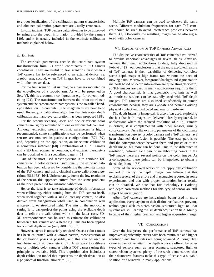
(a) Depth colored point cloud of a statichand
(b) Depth colored point cloud of a handmoving to the left
Fig. 11. Motion blurring appears due to a quick movement of the cameraor the objects in the scene during the integration time. Its effect can be seenby comparing subfigures (a) and (b).
a mathematical model [52]. Because empiric parametrisationwas still needed, further research must be carried out tooptimally mitigate its effect. Instead of trying to detect anddecrease the scattering effect, some researchers point outthatnew sensor materials with lower reflectivity will arise in thefuture that will make scattering negligible [50].
Motion blurring , present when traditional cameras are usedin dynamic environments, appears also with ToF cameras. Thisis due to the physical motion of the objects or the cameraduring the integration time used for sampling (see Fig. 11).
Motion blurring errors can be classified in two different
types of artifacts depending on whether their appearance isdue to lateral or axial motion. In [54] a combination of aconventional 2D image sensor and a PMD camera is usedin order to detect lateral motion artifacts by means of aclassical 2D image edge detector. Instead of discarding thecorrupted data, the authors present two possible correctionapproaches. On the one hand, an average of positionallyweighted neighbouring pixels is recommended, and on theother hand, after a phase sampling analysis of images, 2 phasedepth computation can be used instead of the common 4 phasealgorithm. Another approach, this time for solving both lateraland axial motion blurring consecutively, is presented in [55].Lateral motion artifacts are identified first, by estimatingopticflow from some pre-processed phase-sampled images, andafterwards, axial motion artifacts are removed using both anaxial motion estimation approach and a theoretical model foraxial motion deviation errors.
V. I NTRINSIC AND EXTRINSIC CALIBRATION
While the error compensation procedures described in thepreceding section are specific of ToF cameras (with the ex-ception of those dealing with motion blurring), the calibrationtechniques explained next are mostly similar to those usedfor traditional cameras that provide depth through stereo orstructured light.
A. Intrinsic
3D data are not delivered in the same manner by all differentcamera models, i.e. SR3 delivers cartesian 3D points, whilePMD delivers the absolute distance to the center of projectionof the optical system. The pinhole model and the intrinsiccalibration parameters [40], [45] are needed to compute carte-sian 3D points from depth points. This is mandatory for PMDcameras. For SwissRanger cameras, some authors recomputedepth maps with the obtained focal depth to improve depthprecision. As shown below, intrinsic parameters are also usefulwhen ToF camera images have to be combined with othersensors.
Intrinsic camera parameters have often been obtained byapplying classical calibration procedures based on intensityimages and calibration patterns [34], [38], [56]. Alternatively,using an array of infrared LEDs has been also proposed toimprove the localization of the calibration pattern [33]. How-ever, the characteristic low resolution of these cameras leads
IEEE SENSORS JOURNAL, VOL. 11, NO. 3, MARCH 2011 8
to a poor localization of the calibration pattern characteristicsand obtained calibration parameters are usually erroneous.
In sum, intrinsic TOF camera calibration has to be improvedby using also the depth information provided by the camera[40], and it is usually included in the extrinsic calibrationmethods explained below.
B. Extrinsic
The extrinsic parameters encode the coordinate systemtransformation from 3D world coordinates to 3D cameracoordinates. They are useful in two scenarios: first when aToF camera has to be referenced to an external device, i.e.a robot arm; second, when ToF images have to be combinedwith other sensor data.
For the first scenario, let us imagine a camera mounted onthe end-effector of a robotic arm. As will be presented inSec. VI, this is a common configuration e.g. for object mod-elling [24]. The transformation between the robot coordinatesystem and the camera coordinate system is the so-called hand-eye calibration. To compute it, the image measures have to beused. Recently, a calibration algorithm that integrates depthcalibration and hand-eye calibration has been proposed [38].
For the second scenario, lasers and one or various colorcameras are rigidly mounted with one or various ToF cameras.Although extracting precise extrinsic parameters is highlyrecommended, some simplifications can be performed whensensors are mounted in particular configurations [57]–[59],and, depending on the application, an inaccurate calibrationis sometimes sufficient [60]. Combination of a ToF cameraand a 2D laser scanner is common, and extrinsic parameterscan be obtained with a specialised pattern [61].
One of the most used sensor systems is to combine ToFcameras with color cameras. Traditionally the extrinsic cali-bration has been addressed by considering the intensity imageof the ToF camera and using classical stereo calibration algo-rithms [56], [62]–[64]. Unfortunately, due to the low resolutionof the sensor, this approach suffers from the same problemsas the ones presented for intrinsic calibration.
Hence the idea is to take advantage of depth informationwhen calibrating, either coming from the ToF camera itself,when used together with a single intensity camera, or alsoderived from triangulation when used in combination witha stereo rig or structured light. The aim in the monocularsetting is to backproject the points using the available depthdata to refine the calibration, while in the latter case, 3D-3D correspondences can be used to estimate the calibrationbetween a ToF camera and a stereo rig. This has been appliedfor a small depth range (only 400mm) [65].
However, stereo is not strictly required. Once a color camerahas been calibrated with a known pattern, reconstruction ofthe calibration poses is possible, and this can be used tofind better extrinsic parameters [37]. A software to calibrateone or multiple color cameras with a TOF camera using thisprinciple is available [66]. This algorithm also includes adepth calibration model that represents the depth deviation asa polynomial function, similar to [38].
Multiple ToF cameras can be used to observe the samescene. Different modulation frequencies for each ToF cam-era should be used to avoid interference problems betweenthem [41]. Obviously, the resulting images can be also regis-tered with color cameras.
VI. EXPLOITATION OF TOF CAMERA ADVANTAGES
The distinctive characteristics of ToF cameras have provedto provide important advantages in several fields. After re-viewing their main applications to date, fully discussed inFoix et al. [2], our conclusion is that the most exploited featureof ToF cameras is their capability of delivering completescene depth maps at high frame rate without the need ofmoving parts. Moreover, foreground/background segmentationmethods based on depth information are quite straightforward,so ToF images are used in many applications requiring them.A good characteristic is that geometric invariants as wellas metric constraints can be naturally used with ToF depthimages. ToF cameras are also used satisfactorily in humanenvironments because they are eye-safe and permit avoidingphysical contact and dedicated markers or hardware.
The depth-intensity image pair is also often used, exploitingthe fact that both images are delivered already registered.Inapplications where the reduced resolution of a ToF camerais critical, it is complemented with other sensors, usuallycolor cameras. Once the extrinsic parameters of the coordinatetransformation between a color camera and a ToF camera havebeen obtained, data fusion is possible. The easy part is tofind the correspondences between them and put color to thedepth image, but more can be done. Due to the difference inresolution, between each pair of neighbouring points in theToF image there are several points on the color image. Asa consequence, these points can be interpolated to obtain adense depth map [56].
Some of the reviewed works do not apply any calibrationmethod to rectify the depth images. We believe that thisexplains several of the errors and inaccuracies reported insomeexperiments, and that with proper calibration better resultscan be obtained. We note that ToF technology is evolvingand depth correction methods for this type of sensor are stillsubject to investigation.
Albeit ToF cameras are increasingly being used in moreapplications everyday due to their distinctive features, previoustechnologies such as stereo vision, structured light or lidarsystems are still leading the 3D depth acquisition field. Mainlybecause of their higher precision and higher acquisition range.
VII. C ONCLUSIONS
Over the last years, the performance of ToF cameras hasimproved significantly; errors have been minimised and higherresolution and frame rates are being obtained. Although ToFcameras cannot yet attain the depth accuracy offered by othertypes of sensors such as laser scanners, structured light orstereo vision systems, plenty of research demonstrates thattheir distinctive features make this type of sensors a suitablesolution or alternative in many applications.
IEEE SENSORS JOURNAL, VOL. 11, NO. 3, MARCH 2011 9
Advantages of this type of sensors are multiple, as demon-strated in the previous sections: they are compact and portable,easing movement; they make data extraction simpler andquicker, reducing power consumption and computational time;and they offer a combination of images that show greatpotential in the development of data feature extraction, regis-tration, reconstruction, planning and optimisation algorithms,among other positive characteristics. Thus, ToF cameras proveto be especially adequate for real-time applications and, inparticular, for automatic acquisition of 3D models requiringsensor movement and on-line mathematical calculation.
Finally, some broad challenges need to be mentioned. First,resolution is still generally low for ToF cameras, despite someefforts have already led to better resolutions as explainedabove. Second, short integration times contribute to obtain astrong noise ratio, and high integration times can result inpixelsaturation [67]. Although some algorithms dealing with thisproblem have already been proposed, more research is neededin this direction. Third, an important issue for ToF camerasisthe wrapping effect, a consequence of the periodicity of themodulated signal. Distances to objects that differ 360◦ in phaseare indistinguishable. Use of multiple modulated frequenciescan be a solution here, or lowering the modulation frequencysince it would increase the unambiguous metric range.
Other concerns include ambient light noise, motion artifactsand high-reflectivity surfaces in the scene. Ambient light maycontain unwanted light of the same wavelength as that ofthe ToF light source which may cause false measurementsin the sensor. Frequency-based filters can be used in orderto minimise this effect. Motion artifacts are errors causedbyreceiving light from different depths at the same time due toobject motion in the scene. This type of errors are mostlyobserved around the edges of the moving object and can beattenuated by either increasing the frame rate, or by correctionusing motion estimation. Finally, errors due to the coexistenceof low-reflective and high-reflective objects (mirroring effect)can be addressed by combining multiple exposure settings.
REFERENCES
[1] T. Spirig, P. Seitz, O. Vietze, and F. Heitger, “The lock-in CCD - two-dimensional synchronous detection of light,”IEEE J. Quantum Electron.,vol. 31, no. 9, pp. 1705–1708, Sept. 1995.
[2] S. Foix, G. Alenya, and C. Torras, “Exploitation of Time-of-Flight (ToF)cameras,” IRI, UPC, Tech. Rep. IRI-DT-10-07, 2010.
[3] “SR-Cameras, http://www.mesa-imaging.ch.” MESA Imaging AG,2009.
[4] “3D vision sensors, http://www.ifm.com.” Ifm electronic gmbh, 2009.[5] “Camera Modules, http://www.canesta.com.” CanestaVisionTM , 2009.[6] “PMD-Cameras, http://www.pmdtec.com.” PMDTechnologies GmbH,
2009.[7] S. Gokturk, H. Yalcin, and C. Bamji, “A time-of-flight depth sensor
- system description, issues and solutions,” inProc. IEEE CVPRWorkshops, Washington, D. C., June 2004, pp. 35–35.
[8] Z. Xu, R. Schwarte, H. Heinol, B. Buxbaum, and T. Ringbeck, “Smartpixel - photonic mixer device (PMD) / New System Concept of a 3D-imaging-on-a-chip,” inProc. 5th Int. Conf. Mechatronics and MachineVision in Practice, Nanjing, Sep. 1998, pp. 259–264.
[9] R. Lange and P. Seitz, “Solid-state time-of-flight rangecamera,”IEEEJ. Quantum Electron., vol. 37, no. 3, pp. 390–397, Mar. 2001.
[10] T. Oggier, M. Lehmann, R. Kaufmann, M. Schweizer, M. Richter,P. Metzler, G. Lang, F. Lustenberger, and N. Blanc, “An all-solid-stateoptical range camera for 3D real-time imaging with sub-centimeter depthresolution (SwissRangerTM ),” in Proc. of SPIE, vol. 5249, no. 1, St.Etienne, Feb. 2004, pp. 534–545.
[11] J. Weingarten, G. Gruener, and R. Siegwart, “A state-of-the-art 3Dsensor for robot navigation,” inProc. IEEE/RSJ Int. Conf. Intell. RobotsSyst., vol. 3, Sendei, Sep. 2004, pp. 2155–2160.
[12] A. Kolb, E. Barth, and R. Koch, “ToF-sensors: New dimensions forrealism and interactivity,” inProc. IEEE CVPR Workshops, vol. 1-3,Anchorage, June 2008, pp. 1518–1523.
[13] C. Niclass, C. Favi, T. Kluter, F. Monnier, and E. Charbon, “Single-photon synchronous detection,”IEEE J. Solid-State Circuits, vol. 44,no. 7, pp. 1977–1989, 2009.
[14] D. Stoppa, L. Pancheri, M. Scandiuzzo, L. Gonzo, G.-F. D. Betta, andA. Simoni, “A CMOS 3-D imager based on single photon avalanchediode,” IEEE Trans. Circuits Syst., vol. 54, no. 1, pp. 4–12, 2007.
[15] F. Blais, “Review of 20 years of range sensor development,” J. ElectronicImag., vol. 13, no. 1, pp. 231–243, 2004.
[16] E. Stoykova, A. Alatan, P. Benzie, N. Grammalidis, S. Malassiotis, J. Os-termann, S. Piekh, V. Sainov, C. Theobalt, T. Thevar, and X. Zabulis,“3-D time-varying scene capture technologies: a survey,”IEEE Trans.Circuits Syst. Video Technol., vol. 17, no. 11, pp. 1568–1586, Nov. 2007.
[17] R. Hartley and A. Zisserman,Multiple View Geometry in ComputerVision, 2nd ed. Cambridge: Cambridge University Press, 2004.
[18] F. Moreno-Noguer, P. N. Belhumeur, and S. K. Nayar, “Active refocusingof images and videos,”ACM T. Graphics, vol. 26, no. 3, July 2007.
[19] J. Andrade-Cetto and A. Sanfeliu,Environment Learning for IndoorMobile Robots. A Stochastic State Estimation Approach to SimultaneousLocalization and Map Building, ser. Springer Tracts in AdvancedRobotics. Springer, 2006, vol. 23.
[20] A. Prusak, O. Melnychuk, H. Roth, I. Schiller, and R. Koch, “Poseestimation and map building with a time-of-flight camera forrobotnavigation,” Int. J. Int. Syst. Tech. App., vol. 5, no. 3-4, pp. 355–364,2008.
[21] S. May, D. Droeschel, D. Holz, C. Wiesen, and S. Fuchs, “3D poseestimation and mapping with time-of-flight cameras,” inProc. IEEE/RSJIROS Workshop on 3D-Mapping, Nice, Sep. 2008.
[22] S. Hussmann and T. Liepert, “Robot vision system based on a 3D-ToFcamera,” inProc. 24th IEEE Instrum. and Meas. Tech. Conf., vol. 1-5,Warsaw, May 2007, pp. 1405–1409.
[23] B. Dellen, G. Alenya, S. Foix, and C. Torras, “3D objectreconstructionfrom Swissranger sensors data using a spring-mass model,” in Proc. 4thInt. Conf. Comput. Vision Theory and Applications, vol. 2, Lisbon, Feb.2009, pp. 368–372.
[24] S. Foix, G. Alenya, J. Andrade-Cetto, and C. Torras, “Object modelingusing a ToF camera under an uncertainty reduction approach,” in Proc.IEEE Int. Conf. Robot. Automat., Anchorage, May 2010, pp. 1306–1312.
[25] X. Liu and K. Fujimura, “Hand gesture recognition usingdepth data,” inProc. 6th IEEE Int. Conf. Automatic Face Gesture Recog., Seoul, May2004, pp. 529–534.
[26] S. B. Gokturk and C. Tomasi, “3D head tracking based on recognitionand interpolation using a time-of-flight depth sensor,” inProc. 18th IEEEConf. Comput. Vision Pattern Recog., vol. 2, Washington DC, June-July2004, pp. 211–217.
[27] K. Nanda, H.; Fujimura, “Visual tracking using depth data,” in Proc.IEEE CVPR Workshops, vol. 3, Washington, D. C., June 2004, pp. 37–37.
[28] W. Karel, P. Dorninger, and N. Pfeifer, “In situ determination of rangecamera quality parameters by segmentation,” inProc. 8th Int. Conf. onOpt. 3D Meas. Tech., Zurich, July 2007, pp. 109 – 116.
[29] S. A. Guomundsson, H. Aanæs, and R. Larsen, “Environmental effectson measurement uncertainties of time-of-flight cameras,” in Proc. Int.Sym. Signals, Circuits and Systems, vol. 1-2, Lasi, July 2007, pp. 113–116.
[30] C. A. Weyer, K. H. Bae, K. Lim, and D. D. Lichti, “Extensive metricperformance evaluation of a 3D range camera,” inProc. ISPRS Conf.,vol. 37, Beijing, Jul. 2008, pp. 939–944.
[31] M. Keller and A. Kolb, “Real-time simulation of time-of-flight sensors,”Sim. Mod. Pract. Theory, vol. 17, pp. 967–978, May. 2009.
[32] R. Lange, “3D time-of-flight distance measurement withcustom solid-state image sensors in CMOS/CCD-technoloty,” Ph.D. dissertation,Univ. Siegen, Germany, 2000.
[33] T. Kahlmann, F. Remondino, and H. Ingensand, “Calibration for in-creased accuracy of the range imaging camera SwissrangerTM ,” inISPRS Commission V Symposium, Dresden, Sep. 2006, pp. 136–141.
[34] M. Lindner and A. Kolb, “Lateral and depth calibration of PMD-distanceSensors,” inProc. 2nd Int. Sym. Visual Computing, vol. 4292, LakeTahoe, Nov. 2006, pp. 524–533.
[35] ——, “Calibration of the intensity-related distance error of the PMDToF-camera,” inProc. SPIE, vol. 6764, no. 67640W, Boston, Sept. 2007.
IEEE SENSORS JOURNAL, VOL. 11, NO. 3, MARCH 2011 10
[36] M. Lindner, A. Kolb, and T. Ringbeck, “New insights intothe calibrationof ToF-sensors,” inProc. 22nd IEEE Conf. Comput. Vision PatternRecog., vol. 1-3, Anchorage, June 2008, pp. 1603–1607.
[37] I. Schiller, C. Beder, and R. Koch, “Calibration of a PMDcamera usinga planar calibration object together with a multi-camera setup,” in Proc.ISPRS Conf., vol. 37. Part B3a, Beijing, Jul. 2008, pp. 297–302.
[38] S. Fuchs and S. May, “Calibration and registration for precise surfacereconstruction with time of flight cameras,”Int. J. Int. Syst. Tech. App.,vol. 5, no. 3-4, pp. 274–284, 2008.
[39] S. Fuchs and G. Hirzinger, “Extrinsic and depth calibration of ToF-cameras,” inProc. 22nd IEEE Conf. Comput. Vision Pattern Recog.,vol. 1-12, Anchorage, June 2008, pp. 3777–3782.
[40] M. Wiedemann, M. Sauer, F. Driewer, and K. Schilling, “Analysis andcharacterization of the PMD camera for application in mobile robotics,”in Proc. 17th IFAC World Congress on Aut. Control, Seoul, July 2008,pp. 13 689–13 694.
[41] Y. M. Kim, D. Chan, C. Theobalt, and S. Thrun, “Design andcalibrationof a multi-view ToF sensor fusion system,” inProc. IEEE CVPRWorkshops, vol. 1-3, Anchorage, June 2008, pp. 1524–1530.
[42] S. Oprisescu, D. Falie, M. Ciuc, and V. Buzuloiu, “Measurements withToF cameras and their necessary corrections,” inProc. Int. Sym. Signals,Circuits and Systems, vol. 1-2, Lasi, July 2007, pp. 221–224.
[43] J. Radmer, P. Fuste, H. Schmidt, and J. Kruger, “Incident light relateddistance error study and calibration of the PMD-range imaging camera,”in Proc. IEEE CVPR Workshops, vol. 1-3, Anchorage, June 2008, pp.1579–1584.
[44] S. May, S. Fuchs, D. Droeschel, D. Holz, and A. Nuechter,“Robust3D-mapping with time-of-flight cameras,” inProc. IEEE/RSJ Int. Conf.Intell. Robots Syst., Saint Louis, Oct. 2009, pp. 1673–1678.
[45] H. Rapp, “Experimental and theoretical investigationof correlating ToF-camera systems,” Master’s thesis, University of Heidelberg, Sept. 2007.
[46] D. Falie and V. Buzuloiu, “Distance errors correction for the time-of-flight (ToF) cameras,” inProc. IEEE Int. Workshop Imag. Syst. Tech.,Chania, Sep. 2008, pp. 123–126.
[47] ——, “Noise characteristics of 3D time-of-flight cameras,” in Proc. Int.Sym. Signals, Circuits and Systems, vol. 1-2, Lasi, July 2007, pp. 229–232.
[48] O. Steiger, J. Felder, and S. Weiss, “Calibration of time-of-flight rangeimaging cameras,” inProc. IEEE Int. Conf. Image Process., San Diego,Oct. 2008, pp. 1968–1971.
[49] F. Chiabrando, R. Chiabrando, D. Piatti, and F. Rinaudo, “Sensors for3D imaging: metric evaluation and calibration of a CCD/CMOStime-of-flight camera,”Sensors, vol. 9, no. 12, pp. 10 080–10 096, 2009.
[50] T. Kahlmann and H. Ingensand, “Calibration and development forincreased accuracy of 3D range imaging cameras,”J. Appl. Geodesy,vol. 2, no. 1, pp. 1–11, 2008.
[51] W. Karel, “Integrated range camera calibration using image sequencesfrom hand-held operation,” inProc. ISPRS Conf., vol. 37, Beijing, Jul.2008, pp. 945–952.
[52] J. Mure-Dubois and H. Hugli, “Real-time scattering compensation fortime-of-flight camera,” inProc. 5th Int. Conf. Comput. Vision Systems,Bielefeld, March 2007.
[53] S. May, B. Werner, H. Surmann, and K. Pervolz, “3D time-of-flightcameras for mobile robotics,” inProc. IEEE/RSJ Int. Conf. Intell. RobotsSyst., vol. 1-12, Beijing, Oct. 2006, pp. 790–795.
[54] O. Lottner, A. Sluiter, K. Hartmann, and W. Weihs, “Movement artefactsin range images of time-of-flight cameras,” inProc. Int. Sym. Signals,Circuits and Systems, vol. 1-2, Lasi, July 2007, pp. 117–120.
[55] M. Lindner and A. Kolb, “Compensation of motion artifacts for time-of-flight cameras,” inProc. Dynamic 3D Vision Workshop, vol. 5742,Jena, Sep. 2009, pp. 16–27.
[56] M. Lindner, A. Kolb, and K. Hartmann, “Data-fusion of PMD-baseddistance-information and high-resolution RGB-images,” in Proc. Int.Sym. Signals, Circuits and Systems, vol. 1-2, Lasi, July 2007, pp. 121–124.
[57] K. D. Kuhnert and M. Stommel, “Fusion of stereo-camera and PMD-camera data for real-time suited precise 3D environment reconstruction,”in Proc. IEEE/RSJ Int. Conf. Intell. Robots Syst., vol. 1-12, Beijing, Oct.2006, pp. 4780–4785.
[58] F. Wallhoff, M. Russ, G. Rigoll, J. Gobel, and H. Diehl, “Improvedimage segmentation using photonic mixer devices,” inProc. IEEE Int.Conf. Image Process., vol. 1-7, San Antonio, Sep. 2007, pp. 2849–2852.
[59] S. A. Guomundsson, R. Larsen, H. Aanæs, M. Pardas, and J.R. Casas,“ToF imaging in smart room environments towards improved peopletracking,” in Proc. IEEE CVPR Workshops, vol. 1-3, Anchorage, June2008, pp. 1486–1491.
[60] U. Hahne and M. Alexa, “Combining time-of-flight depth and stereoimages without accurate extrinsic calibration,”Int. J. Int. Syst. Tech.App., vol. 5, no. 3-4, pp. 325–333, 2008.
[61] F. Yuan, A. Swadzba, R. Philippsen, O. Engin, M. Hanheide, , andS. Wachsmuth, “Laser-based navigation enhanced with 3D time of flightdata,” in Proc. IEEE Int. Conf. Robot. Automat., Kobe, May 2009, pp.2844–2850.
[62] J. Fischer, B. Huhle, and A. Schilling, “Using time-of-flight range datafor occlusion handling in augmented reality,” inProc. Eurographics Sym.Virtual Environments, Sep. 2007, pp. 109–116.
[63] S. A. Guomundsson, H. Aanæs, and R. Larsen, “Fusion of stereo visionand time-of-flight imaging for improved 3D estimation,”Int. J. Int. Syst.Tech. App., vol. 5, no. 3-4, pp. 425–433, 2008.
[64] T. Grundmann, Z. Xue, J. Kuehnle, R. Eidenberger, S. Ruehl, A. Verl,R. D. Zoellner, J. M. Zoellner, and R. Dillmann, “Integration of 6Dobject localization and obstacle detection for collision free robotic ma-nipulation,” in Proc. IEEE/SICE Int. Sym. System Integration, Nagoya,Dec. 2008, pp. 66–71.
[65] J. Zhu, L. Wang, R. Yang, and J. Davis, “Fusion of time-of-flight depthand stereo for high accuracy depth maps,” inProc. 22nd IEEE Conf.Comput. Vision Pattern Recog., vol. 1-12, Anchorage, June 2008, pp.3262–3269.
[66] “http://mip.informatik.uni-kiel.de,” 2009.[67] P. Einramhof, S. Olu, and M. Vincze, “Experimental evalutation of state
of the art 3D-sensors for mobile robot navigation,” inProc. in the 31stAustrian Associantion for Pattern Recog. Workshop (OAGM), Krumbach,May 2007.
Sergi Foix is a JAE predoc fellow at the SpanishScientific Research Council (CSIC). He receivedM.Sc. degrees in Intelligent Systems and AutomaticControl and Robotics from the University of Sun-derland and the Technical University of Catalonia(UPC), respectively. His fields of interest are next-best-view planning for active vision, 3D object mod-elling and pose estimation for robot manipulation,and 3D feature extraction.
Guillem Alenya is a JAE postdoc fellow at theSpanish Scientific Research Council (CSIC). Hereceived Ph.D. degree in 2007 from the TechnicalUniversity of Catalonia (UPC) with a work onmobile robot navigation using active contours. Heparticipates in numerous scientific and technologicalprojects involving image understanding and robotlocalization. Dr Alenya was a Marie Curie fellow ofthe European Comission in the period 2002-2004.His areas of interest include robot active vision,egomotion estimation, and planning for active mod-
elling.
IEEE SENSORS JOURNAL, VOL. 11, NO. 3, MARCH 2011 11
Carme Torras (M’07) is Research Professor atthe Spanish Scientific Research Council (CSIC).She received M.Sc. degrees in Mathematics andComputer Science from the Universitat de Barcelonaand the University of Massachusetts, respectively,and a Ph.D. degree in Computer Science from theTechnical University of Catalonia (UPC). Prof. Tor-ras has published five books and about two hundredpapers in the areas of robotics, computer vision, andneurocomputing. She has been local project leader ofseveral European projects, such as “Planning RObot
Motion” (PROMotion), “Robot Control based on Neural Network Systems”(CONNY),“Self-organization and Analogical Modelling using SubsymbolicComputing” (SUBSYM), “Behavioural Learning: Sensing and Acting” (B-LEARN), the 6th framework IP project “Perception, Action and COgnitionthrough Learning of Object-Action Complexes” (PACO-PLUS), and theongoing 7th framework STREP projects “GARdeNIng with a CognitiveSystem” (GARNICS) and “Intelligent observation and execution of Actionsand manipulations” (IntellAct).