Embed Size (px)
Citation preview
IEEE TRANSACTIONS ON PATTERN ANALYSIS AND MACHINE INTELLIGENCE 1
Coded Strobing Photography: Compressive Sensingof High-speed Periodic Events
Ashok Veeraraghavan∗, Member, IEEE,Dikpal Reddy∗, Student Member, IEEE,and Ramesh Raskar,Member, IEEE
Abstract—We show that, via temporal modulation, one canobserve a high-speed periodic event well beyond the abilitiesof a low-frame rate camera. By strobing the exposure withunique sequences within the integration time of each frame,we take coded projections of dynamic events. From a sequenceof such frames, we reconstruct a high-speed video of the highfrequency periodic process. Strobing is used in entertainment,medical imaging and industrial inspection to generate lowerbeat frequencies. But this is limited to scenes with a detectablesingle dominant frequency and requires high-intensity lighting.In this paper, we address the problem of sub-Nyquist sampling ofperiodic signals and show designs to capture and reconstruct suchsignals. The key result is that for such signals the Nyquist rateconstraint can be imposed on strobe-rate rather than the sensor-rate. The technique is based on intentional aliasing of the fre-quency components of the periodic signal while the reconstructionalgorithm exploits recent advances in sparse representations andcompressive sensing. We exploit the sparsity of periodic signalsin Fourier domain to develop reconstruction algorithms that areinspired by compressive sensing.
Index Terms—Computational imaging, High-speed imaging,Compressive sensing, Stroboscopy
I.I NTRODUCTION
Periodic signals are all around us. Several human and animalbiological processes such as heart-beat, breathing, several cel-lular processes, industrial automation processes and everydayobjects such as hand-mixer and blender all generate periodicprocesses. Nevertheless, we are mostly unaware of the innerworkings of some of these high-speed processes because theyoccur at a far greater speed than can be perceived by the humaneye. Here, we show a simple but effective technique that canturn an off-the-shelf video camera into a powerful high-speedvideo camera for observing periodic events.
Strobing is often used in entertainment, medical imaging andindustrial applications to visualize and capture high-speedvisual phenomena. Active strobing involves illuminating thescene with a rapid sequence of flashes within a frame time. Theclassic example is Edgerton’s Rapatron to capture a golf swing[13]. In modern sensors, it is achieved passively by multiple-exposures within a frame time [37][28] or fluttering [29]. Weuse the term ‘strobing’ to indicate both active illumination andpassive sensor methods.
In case of periodic phenomenon, strobing is commonly usedto achieve aliasing and generate lower beat frequencies. Whilestrobing performs effectively when the scene consists of asingle frequency with a narrow sideband, it is difficult to visu-alize multiple or a wider band of frequencies simultaneously.
∗ Ashok Veeraraghavan and Dikpal Reddy contributed equally to this work.
Periodic phenomenon with unknown period P (say 16 ms)
Video camera w/ frame rate f s = 25fps
Every frame is modulated U = 80 times with a unique binary code by
opening & closing the shutter
Capture M = 125 frames in 5s
Computationally reconstruct N = 10000 frames
Coded Strobing Schematic
Structured sparse recovery
Time Time
Coded Strobing: Time Domain
Coded Strobing: Frequency Domain
tP = 16ms
At each pixel, the periodic signal is temporally modulated with a binary code
TFrame= Frame Duration = 40ms
At a pixel, the M observed intensity values are linear combinations of the periodic signal’s sparse Fourier coefficients
Binary code of length U=80
Measure Linear Combinations
4fP
Structured Sparsity Enforcing Reconstruction Algorithm
0 fMax- fMax fP=1/P 2fP-fP-2fP4fP
f
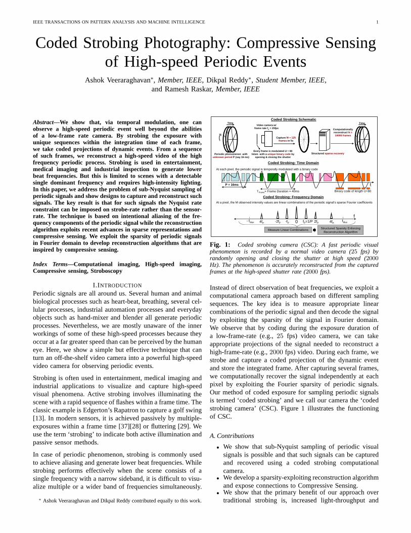
Fig. 1: Coded strobing camera (CSC): A fast periodic visualphenomenon is recorded by a normal video camera (25 fps) byrandomly opening and closing the shutter at high speed (2000
Hz). The phenomenon is accurately reconstructed from the capturedframes at the high-speed shutter rate (2000 fps).
Instead of direct observation of beat frequencies, we exploit acomputational camera approach based on different samplingsequences. The key idea is to measure appropriate linearcombinations of the periodic signal and then decode the signalby exploiting the sparsity of the signal in Fourier domain.We observe that by coding during the exposure duration ofa low-frame-rate (e.g.,25 fps) video camera, we can takeappropriate projections of the signal needed to reconstruct ahigh-frame-rate (e.g.,2000 fps) video. During each frame, westrobe and capture a coded projection of the dynamic eventand store the integrated frame. After capturing several frames,we computationally recover the signal independently at eachpixel by exploiting the Fourier sparsity of periodic signals.Our method of coded exposure for sampling periodic signalsis termed ‘coded strobing’ and we call our camera the ‘codedstrobing camera’ (CSC). Figure 1 illustrates the functioningof CSC.
A. Contributions
• We show that sub-Nyquist sampling of periodic visualsignals is possible and that such signals can be capturedand recovered using a coded strobing computationalcamera.
• We develop a sparsity-exploiting reconstruction algorithmand expose connections to Compressive Sensing.
• We show that the primary benefit of our approach overtraditional strobing is, increased light-throughput and
IEEE TRANSACTIONS ON PATTERN ANALYSIS AND MACHINE INTELLIGENCE 2
ability to tackle multiple frequencies simultaneously post-capture.
B. Benefits and limitationsThe main constraint for recording a high-speed event islight throughput . We overcome this constraint for periodicsignals via sufficient exposure duration (in each frame) andextended observation window (multiple frames). For well-lit non-periodic events, high-speed cameras are ideal. Fora static snapshot, a short exposure photo (or single frameof the high-speed camera) is sufficient. In both cases, lightthroughput is limited but unavoidable. Periodic signals canalso be captured with high-speed camera. But one will needa well-lit scene or must illuminate it with unrealistic brightlights. For example, if we use a2000 fps camera for vocalcord analysis instead of strobing using a laryngoscope, wewould need a significantly brighter illumination source andthis creates the risk of burn injuries to the throat. A saferoption would be25 fps camera with strobed light source andthen exploit the periodicity of vocal fold movement. Here, weshow that an even better option in terms of light-throughputis a computational camera approach. Further, the need toknow frequency of the signal at capture-time is also avoided.Moreover, the computational recovery algorithm can tacklethe presence of multiple fundamental frequencies in a scene,which poses a challenge to traditional strobing.
C. Related workHigh-speed imaging hardware:Capturing high-speed eventswith fast, high-frame rate cameras require imagers with highphotoresponsivity at short integration times, synchronous ex-posure and high-speed parallel readout due to the necessarybandwidth. In addition, they suffer from challenging storageproblems. A high-speed camera also fails to exploit the inter-frame coherence, while our technique takes advantage ofa simplified model of motion. Edgerton and others haveshown visually stunning results for high-speed objects usingextremely narrow-duration flash [13]. These snapshots capturean instant of the action but fail to indicate the generalmovement in the scene. Multiple low-frame rate cameras canbe combined to create high-speed sensing. Using a staggeredexposure approach, Shechtman et al. [34] used frames capturedby multiple co-located cameras with overlapped exposuretime. This staggered exposure approach also assisted a novelreconfigurable multi-camera array [38]. Although there arevery few methods to super-resolve a video temporally [15],numerous super-resolution techniques have been proposedto increase the spatial resolution of images. In [17], super-resolution technique to reconstruct a high-resolution imagefrom a sequence of low-resolution images was proposed bybackprojection method. A method to do super-resolution ona low quality image of a moving object by first tracking it,estimating motion and deblurring the motion blur and creatinga high quality image was proposed in [4]. Freeman et al. [14]proposed a learning based technique for superresolution fromone image where the high frequency components like edgesof an image are filled by patches obtained from examples withsimilar low resolution properties. Finally, fundamental limits
on super-resolution for reconstruction based algorithms havebeen explored in [1][22].
Stroboscopy and periodic motion:Stroboscopes (from Greekwordστρωβωσ for ‘whirling’) play an important role in scien-tific research, to study machinery in motion, in entertainmentand medical imaging. Muybridge in his pioneering work usedmultiple triggered cameras to capture high-speed motion ofanimals [25] and proved that all four of a horse’s hooves leftthe ground at the same time during a gallop. Edgerton alsoused flashing lamp to study machine parts in motion [13]. Themost common approaches for “freezing” or “slowing down”the movement are based on temporal aliasing. In medicine,stroboscopes are used to view the vocal cords for diagnosis.The patient hums or speaks into a microphone which in turnactivates the stroboscope at either the same or a slightly lowerfrequency [20],[31]. However, in all healthy humans, vocal-fold vibrations are aperiodic to a greater or lesser degree.Therefore, strobolaryngoscopy does not capture the fine detailof each individual vibratory cycle; rather, it shows a patternaveraged over many successive nonidentical cycles [24][33].Modern strobocopes for machine inspection [11] are designedfor observing fast repeated motions and for determining RPM.The idea can also be used to improve spatial resolution byintroducing high-frequency illumination [16].
Processing:In computer vision, periodic motion of humanshas received significant attention. Seitz et al. [32] introduceda novel motion representation, called the period trace, thatprovides a complete description of temporal variations in acyclic motion, which can be used to detect motion trends andirregularities. A technique to repair videos with large staticbackground or cyclic motion was presented in [18]. Laptev etal. [19] presented a method to detect and segment periodicmotion based on sequence alignment without the need forcamera stabilization and tracking. [5] exploited periodicityof moving objects to perform 3D reconstruction by treatingframes with same phase to be of same pose observed fromdifferent views. In [35], the authors showed a strobe basedapproach for capturing high-speed motion using multiexposureimages obtained within a single frame of a camera. The imagesof a baseball appear as distinct non-overlapping positionsin the image . High temporal and spatial resolution can beobtained via a hybrid imaging device which consists of a highspatial resolution digital camera in conjunction with a highframe-rate but low resolution video camera [6]. In cases wherethe motion can be modeled as linear, there have been severalinteresting methods to engineer the motion blur point spreadfunction so that the blur induced by the imaging device isinvertible. These include coding the exposure [30] and movingthe sensor during the exposure duration [21]. The methodpresented in this paper tackles a different but broadly relatedproblem of reconstructing periodic signals from very low-speed images acquired via a conventional video camera (albeitenhanced with coded exposure).
Comparison with flutter shutter: In [30], the authors showedthat by opening and closing the shutter according to anoptimized coded pattern during the exposure duration of a
IEEE TRANSACTIONS ON PATTERN ANALYSIS AND MACHINE INTELLIGENCE 3
photograph, one can preserve high-frequency spatial details inthe blurred captured image. The image can be then de-blurredusing a manually specified point-spread function. Similarly,we open and close the shutter according to a coded patternand this code is optimized for capture. Nevertheless, therearesignificant differences in motion models and reconstructionprocedures of both these methods. In flutter shutter (FS), aconstant velocity linear motion model was assumed and de-blurring was done in blurred pixels along the motion direction.On the other hand, CSC works even on very complicatedmotion models as long as the motion is periodic. In CSCeach of the captured frames is the result of modulation witha different binary sequence whereas in FS a single frame ismodulated with a ‘all-pass’ code. Further, our method contrastsfundamentally with FS in reconstruction of the frames. InFS the system of equations is not under-determined whereasin CSC we have a severely under-determined system. Weovercome this problem byℓ1-norm regularization, appropriatefor enforcing sparsity of periodic motion in time. In FS asingle system of equations is solved for entire image whereasin CSC at each pixel we temporally reconstruct the periodicsignal by solving an under-determined system.
D. Capture and reconstruction procedureThe sequence of steps involved in capture and reconstructionof a high-speed periodic phenomenon with typical physicalvalues are listed below with references to appropriate sectionsfor detailed discussion.
• Goal: Using a25 fps camera and a shutter which canopen and close at2000 Hz, capture a high-speed periodicphenomenon of unknown period by observing for 5s.
• The length of the binary code needed isN = 2000×5 =10000. For an upsampling factor ofU = 2000/25 =80, find the optimal pseudo random code of lengthN(Section III-A).
• CaptureM = 25 × 5 = 125 frames by fluttering theshutter according to the optimal code. Each capturedframe is an integration of the incoming visual signalmodulated with a corresponding subsequence of binaryvalues of lengthU = 80 (Section II-C).
• Estimate the fundamental frequency of the periodic signal(Section II-D3).
• Using the estimated fundamental frequency, at each pixelreconstruct the periodic signal of lengthN = 10000 fromM = 125 values by recovering the signal’s sparse Fouriercoefficients (Section II-D).
II.STROBING AND L IGHT MODULATION
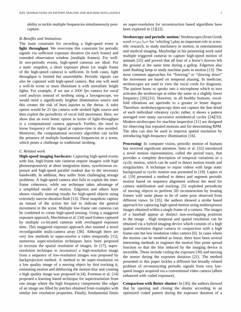
A. Traditional sampling techniquesSampling is the process of converting a continuous domainsignal into a set of discrete samples in a manner that allowsapproximate or exact reconstruction of the continuous domainsignal from just the discrete samples. The most fundamentalresult in sampling is that of Nyquist-Shannon sampling the-orem. Figure 2 provides a graphical illustration of traditionalsampling techniques applied to periodic signals.
Nyquist sampling: Nyquist-Shannon sampling states thatwhen a continuous domain signal is band-limited to[0 , f0]
Hz, one can exactly reconstruct the band-limited signal, byjust observing discrete samples of the signal at a samplingratefs greater than2f0 [27]. When the signal has frequencycomponents that are higher than the prescribed band-limit,thenduring the reconstruction, the higher frequencies get aliased aslower frequencies making the reconstruction erroneous (seeFigure 2(Right)(c)). If the goal is to capture a signal whosemaximum frequencyfMax is 1000 Hz, then one needs a high-speed camera capable of2000 fps in order to acquire thesignal. Such high-speed video cameras are light limited andexpensive.
Band-pass sampling (strobing):If the signal is periodic asshown in Figure 2(Left)(a), then we can intentionally aliasthe periodic signal by sampling at a frequency very close tothe fundamental frequency of the signal as shown in Figure2(Left)(e). This intentional aliasing allows us to measurethe periodic signal. This technique is commonly used forvocal fold visualization [24][33]. However, traditional strobingsuffers from the following limitations. The frequency of theoriginal signal must be known at capture-time so that onemay perform strobing at the right frequency. Secondly, thestrobe signal must be ‘ON’ for a very short duration sothat the observed high-speed signal is not smoothed out andthis makes traditional strobing light-inefficient. Despite thishandicap, traditional strobing is an extremely interesting anduseful visualization tool (and has found several applicationsin varying fields).
Non-uniform sampling: With periodic sampling, aliasingoccurs when the sampling rate is not adequate because, allfrequencies of the formf1+k·fs (k an integer) lead to identicalsamples. One method to counter this problem is to employnon-uniform or random sampling [7][23]. The key idea in non-uniform sampling [7][23] is to ensure a set of sampling instantssuch that the observation sequence for any two frequenciesare different at least in one sampling instant. This scheme hasnever found widespread practical applicability because ofitsnoise sensitivity and light inefficiency.
B. Periodic signalsSince, the focus of this paper is on high-speed video captureofperiodic signals, we first study the properties of such signals.
1) Fourier domain properties of periodic signals:Consider asignal x(t), which has a periodP = 1/fP and a bandlimitfMax. Since the signal is periodic, we can express it as,
x(t) = xDC +
j=Q∑
j=1
aj cos(2πjfP t) + bj sin(2πjfP t) (1)
Therefore, the Fourier transform of the signalx(t) containsenergy only in the frequencies corresponding tojfP , wherej ∈ {−Q,−(Q−1), ...0, 1, ..., Q}. Thus, a periodic signal hasa maximum of(K = 2Q + 1) non-zero Fourier coefficients.Therefore, periodic signals by definition, have a very sparserepresentation in the Fourier domain. Recent advances inthe field of compressed sensing (CS) [12][9][2][8][36] havedeveloped reliable recovery algorithms for inferring sparse rep-resentations if one can measure arbitrary linear combinations
IEEE TRANSACTIONS ON PATTERN ANALYSIS AND MACHINE INTELLIGENCE 4
t
Periodic Signal (x(t)) with period P
P
(a)
P TBox = TFrame
Box filter of duration T Box applied to the periodic signal(b)
t
Normal Video Camera: Frames of the normal camera ca n be treated as the samples (every T Frame) of the output of the above box filter.
PTFrame= Frame Duration
(c)
High-speed Video Camera: Nyquist Sampling of (x(t)) – Since each period of x has very fine high frequency variations Nyquis t sampling rate is very high.
PTs = 1/(2*fMax)
(d)
t
t
Traditional Strobing: Sampling rate of camera is l ow, but the light throughput is also very low in order to avoid blurr ing the features during the strobe time.
P
(e)
t
TStrobe = Strobe Duration TStrobe ~ P
(a)
(b)
Periodic signal with period P, band-limited to f Max. Fourier domain contains only terms that are multiples of f P=1/P
0 fMax- fMax fP=1/P 2fP-fP-2fP
0 fMax- fMaxfB=1/TBox
(c) Normal Camera causes aliasing of high frequency inf ormation ( blue , green , yellow )
0- fMax
0 fMax- fMax
High-speed Video Camera wastes the bandwidth and is inefficient since periodic signal is sparse in the Fourier domain
(d)
0 fMax- fMax
(e)
fMax
Sinc response of the box filter attenuates the harmonics near it’ s zeros ( green ) and the high frequencies ( yellow )
Traditional Strobing requires the period of the sig nal to be known before capture
Time Domain Frequency Domain
Aliasing
t
Coded Strobing: In every exposure duration differen t linear combinations of the underlying periodic signal are observed
P
(f)
Coded strobing is independent of the frequency f P=1/P. Light throughput is on an average 50% which is significantly greater than traditional strobing.
4fP
(f) Coded Strobing: Measure linear combinations of a pe riodic signal’s harmonics.
Measure Linear Combinations
0 fMax- fMax fP=1/P 2fP-fP-2fP4fP
Sparsity Enforcing Reconstruction
f
fS = 1/TFrame= Sampling Frequency
fStrobe = 1/TStrobe ~ fP
Fig. 2: Time domain (Left) and the corresponding frequency domain (Right) characteristics of various sampling techniques as applicableto periodic signals. Note that capturing high-speed visualsignals using normal camera can result in attenuation of high frequencies (b & c)whereas a high-speed camera demands large bandwidth (d) andtraditional strobing is light-inefficient (e). Coded strobing is shown in (f).To illsutrate sampling only two replicas have been shown andnote that colors used in time domain and frequency domain areunrelated.
of the signals. Here, we propose and describe a method formeasuring such linear combinations and use the reconstructionalgorithms inspired by CS to recover the underlying periodicsignal from its low-frame-rate observations.
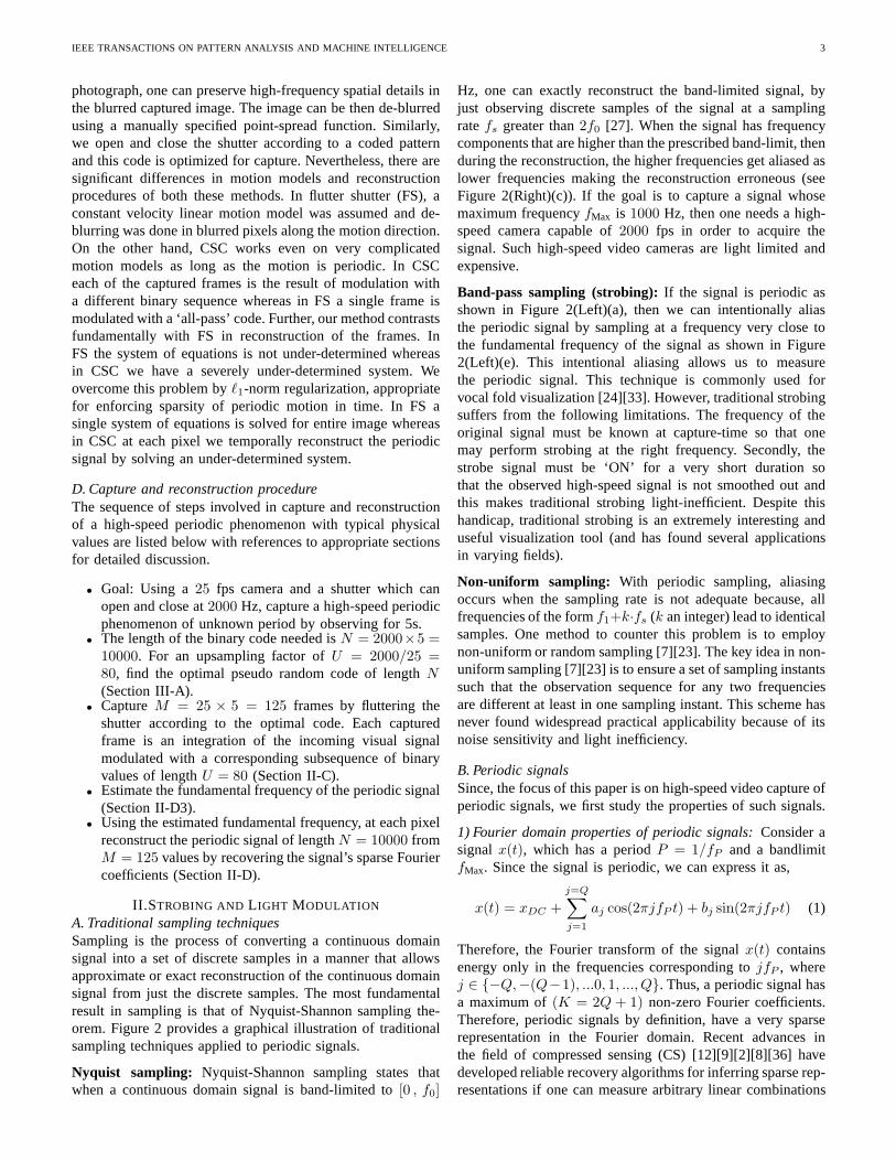
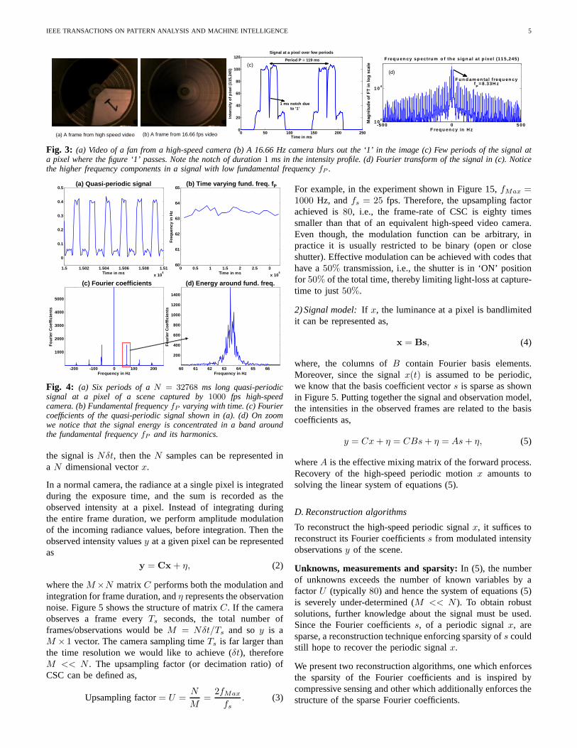
2)Effect of visual texture on periodic motion:Visual texture onsurfaces exhibiting periodic motion introduces high frequencyvariations in the observed signal (Figure 3(d)). As a verysimple instructive example consider the fan shown in Figure3(a). The fan rotates at a relatively slow rate of8.33 Hz. Thiswould seem to indicate that in order to capture the spinningfan one only needs a16.66 fps camera. During exposure timeof 60 ms of a 16.66 Hz camera, the figure ‘1’ written onthe fan blade completes about half a revolution blurring itout (Figure 3(b)). Shown in Figure 3(c) is the time profileof the intensity of a single pixel using a high-speed videocamera. Note that the sudden drop in intensity due to thedark number ‘1’ appearing on the blades persists only forabout 1 millisecond. Therefore, we need a1000 fps high-speed camera to observe the ‘1’ without any blur. In short, thehighest temporal frequency observed at a pixel is a product ofthe highest frequency of the periodic event in time and thehighest frequency of the spatial pattern on the objects acrossthe direction of motion. This makes the capture of high-speedperiodic signals with texture more challenging.
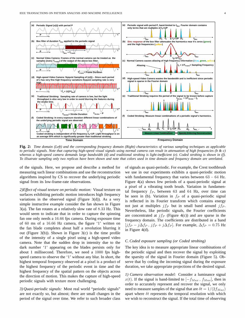
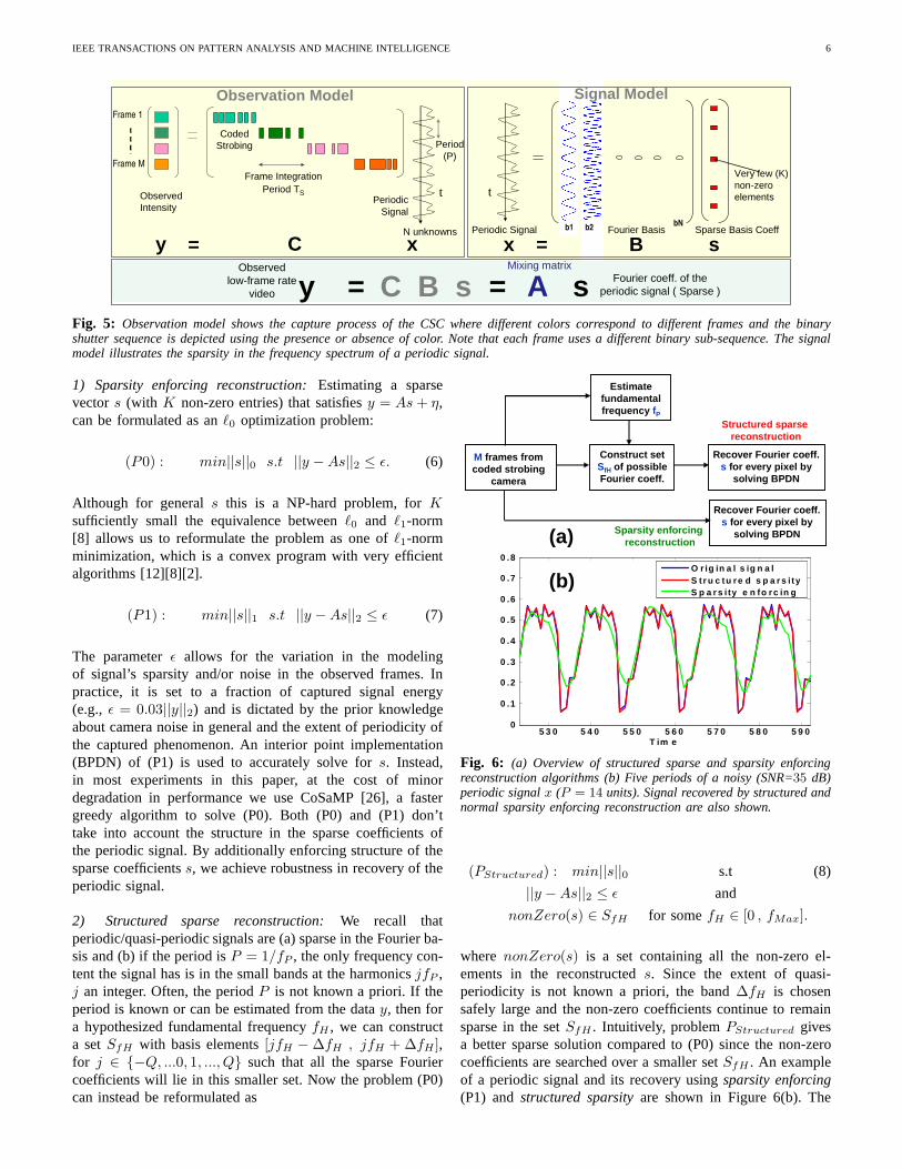
3) Quasi-periodic signals:Most real world “periodic signals”are not exactly so, but almost; there are small changes in theperiod of the signal over time. We refer to such broader class
of signals as quasi-periodic. For example, the Crest toothbrushwe use in our experiments exhibits a quasi-periodic motionwith fundamental frequency that varies between63 − 64 Hz.Figure 4(a) shows few periods of a quasi-periodic signal ata pixel of a vibrating tooth brush. Variation in fundamen-tal frequencyfP , between63 and 64 Hz, over time canbe seen in (b). Variation infP of a quasi-periodic signalis reflected in its Fourier transform which contains energynot just at multiplesjfP but in small band aroundjfP .Nevertheless, like periodic signals, the Fourier coefficientsare concentrated atjfP (Figure 4(c)) and are sparse in thefrequency domain. The coefficients are distributed in a band[jfP − j∆fP , jfP + j∆fP ]. For example,∆fP = 0.75 Hzin Figure 4(d).
C. Coded exposure sampling (or Coded strobing)
The key idea is to measure appropriate linear combinations ofthe periodic signal and then recover the signal by exploitingthe sparsity of the signal in Fourier domain (Figure 5). Ob-serve that by coding the incoming signal during the exposureduration, we take appropriate projections of the desired signal.
1) Camera observation model:Consider a luminance signalx(t). If the signal is band-limited to[−fMax , fMax], then inorder to accurately represent and recover the signal, we onlyneed to measure samples of the signal that areδt = 1/(2fMax)apart whereδt represents the temporal resolution with whichwe wish to reconstruct the signal. If the total time of observing
IEEE TRANSACTIONS ON PATTERN ANALYSIS AND MACHINE INTELLIGENCE 5
(a) A frame from high speed video (b) A frame from 16.66 fps video
-500 0 5 001 0 2
1 0 4
F req u en cy in H z
Mag
nitu
de o
f FT
in lo
g sc
ale
F req u en cy sp ectru m o f th e s ig n a l a t p ixe l (11 5,245)
F u n d am en ta l f req u en cyfP
= 8.33H z
(d)
0 50 100 150 200 2500
20
40
60
80
100
120
Time in ms
Inte
nsity
of p
ixel
(11
5,24
5)
Signal at a pixel over few periods
Period P = 119 ms
1 ms notch dueto '1'
(c)
Fig. 3: (a) Video of a fan from a high-speed camera (b) A 16.66 Hz camera blurs out the ‘1’ in the image (c) Few periods of the signal ata pixel where the figure ‘1’ passes. Note the notch of duration1 ms in the intensity profile. (d) Fourier transform of the signal in (c). Noticethe higher frequency components in a signal with low fundamental frequencyfP .
1.5 1.502 1.504 1.506 1.508 1.51
x 104
0
0.1
0.2
0.3
0.4
0.5
Time in ms0 0.5 1 1.5 2 2.5 3
x 104
60
61
62
63
64
65
Time in ms
Fre
quen
cy in
Hz
-200 -100 0 100 200
1000
2000
3000
4000
5000
Frequency in Hz
Fou
rier
Coe
ffici
ents
60 61 62 63 64 65 66
200
400
600
800
1000
1200
1400
Frequency in Hz
Fou
rier
Coe
ffici
ents
(a) Quasi-periodic signal (b) Time varying fund. freq. f P
(c) Fourier coefficients (d) Energy around fund. fre q.
Fig. 4: (a) Six periods of aN = 32768 ms long quasi-periodicsignal at a pixel of a scene captured by1000 fps high-speedcamera. (b) Fundamental frequencyfP varying with time. (c) Fouriercoefficients of the quasi-periodic signal shown in (a). (d) On zoomwe notice that the signal energy is concentrated in a band aroundthe fundamental frequencyfP and its harmonics.
the signal isNδt, then theN samples can be represented ina N dimensional vectorx.
In a normal camera, the radiance at a single pixel is integratedduring the exposure time, and the sum is recorded as theobserved intensity at a pixel. Instead of integrating duringthe entire frame duration, we perform amplitude modulationof the incoming radiance values, before integration. Then theobserved intensity valuesy at a given pixel can be representedas
y = Cx+ η, (2)
where theM×N matrixC performs both the modulation andintegration for frame duration, andη represents the observationnoise. Figure 5 shows the structure of matrixC. If the cameraobserves a frame everyTs seconds, the total number offrames/observations would beM = Nδt/Ts and soy is aM × 1 vector. The camera sampling timeTs is far larger thanthe time resolution we would like to achieve (δt), thereforeM << N . The upsampling factor (or decimation ratio) ofCSC can be defined as,
Upsampling factor= U =N
M=
2fMax
fs. (3)
For example, in the experiment shown in Figure 15,fMax =1000 Hz, andfs = 25 fps. Therefore, the upsampling factorachieved is80, i.e., the frame-rate of CSC is eighty timessmaller than that of an equivalent high-speed video camera.Even though, the modulation function can be arbitrary, inpractice it is usually restricted to be binary (open or closeshutter). Effective modulation can be achieved with codes thathave a50% transmission, i.e., the shutter is in ‘ON’ positionfor 50% of the total time, thereby limiting light-loss at capture-time to just50%.
2) Signal model:If x, the luminance at a pixel is bandlimitedit can be represented as,
x = Bs, (4)
where, the columns ofB contain Fourier basis elements.Moreover, since the signalx(t) is assumed to be periodic,we know that the basis coefficient vectors is sparse as shownin Figure 5. Putting together the signal and observation model,the intensities in the observed frames are related to the basiscoefficients as,
y = Cx+ η = CBs+ η = As+ η, (5)
whereA is the effective mixing matrix of the forward process.Recovery of the high-speed periodic motionx amounts tosolving the linear system of equations (5).
D. Reconstruction algorithms
To reconstruct the high-speed periodic signalx, it suffices toreconstruct its Fourier coefficientss from modulated intensityobservationsy of the scene.
Unknowns, measurements and sparsity:In (5), the numberof unknowns exceeds the number of known variables by afactorU (typically 80) and hence the system of equations (5)is severely under-determined (M << N ). To obtain robustsolutions, further knowledge about the signal must be used.Since the Fourier coefficientss, of a periodic signalx, aresparse, a reconstruction technique enforcing sparsity ofs couldstill hope to recover the periodic signalx.
We present two reconstruction algorithms, one which enforcesthe sparsity of the Fourier coefficients and is inspired bycompressive sensing and other which additionally enforcesthestructure of the sparse Fourier coefficients.
IEEE TRANSACTIONS ON PATTERN ANALYSIS AND MACHINE INTELLIGENCE 6
y
Observed Intensity
Periodic Signal
Observation Model
C x=
Coded Strobing
Frame 1
Frame M
Frame Integration Period TS
Period (P)
N unknowns
t
Mixing matrixFourier coeff. of the
periodic signal ( Sparse )
Observed low-frame rate
video A sy C B s= =
Very few (K) non-zero elements
Periodic Signal Fourier Basis Sparse Basis Coeff
x = B sb1 b2
bN
Signal Model
t
Fig. 5: Observation model shows the capture process of the CSC wheredifferent colors correspond to different frames and the binaryshutter sequence is depicted using the presence or absence of color. Note that each frame uses a different binary sub-sequence. The signalmodel illustrates the sparsity in the frequency spectrum ofa periodic signal.
1) Sparsity enforcing reconstruction:Estimating a sparsevectors (with K non-zero entries) that satisfiesy = As + η,can be formulated as anℓ0 optimization problem:
(P0) : min||s||0 s.t ||y −As||2 ≤ ǫ. (6)
Although for generals this is a NP-hard problem, forKsufficiently small the equivalence betweenℓ0 and ℓ1-norm[8] allows us to reformulate the problem as one ofℓ1-normminimization, which is a convex program with very efficientalgorithms [12][8][2].
(P1) : min||s||1 s.t ||y −As||2 ≤ ǫ (7)
The parameterǫ allows for the variation in the modelingof signal’s sparsity and/or noise in the observed frames. Inpractice, it is set to a fraction of captured signal energy(e.g., ǫ = 0.03||y||2) and is dictated by the prior knowledgeabout camera noise in general and the extent of periodicity ofthe captured phenomenon. An interior point implementation(BPDN) of (P1) is used to accurately solve fors. Instead,in most experiments in this paper, at the cost of minordegradation in performance we use CoSaMP [26], a fastergreedy algorithm to solve (P0). Both (P0) and (P1) don’ttake into account the structure in the sparse coefficients ofthe periodic signal. By additionally enforcing structure of thesparse coefficientss, we achieve robustness in recovery of theperiodic signal.
2) Structured sparse reconstruction:We recall thatperiodic/quasi-periodic signals are (a) sparse in the Fourier ba-sis and (b) if the period isP = 1/fP , the only frequency con-tent the signal has is in the small bands at the harmonicsjfP ,j an integer. Often, the periodP is not known a priori. If theperiod is known or can be estimated from the datay, then fora hypothesized fundamental frequencyfH , we can constructa setSfH with basis elements[jfH − ∆fH , jfH + ∆fH ],for j ∈ {−Q, ...0, 1, ..., Q} such that all the sparse Fouriercoefficients will lie in this smaller set. Now the problem (P0)can instead be reformulated as
M frames from coded strobing
camera
Estimate fundamental frequency fP
Construct set SfH of possible Fourier coeff.
Recover Fourier coeff. s for every pixel by
solving BPDN
5 3 0 5 4 0 5 5 0 5 6 0 5 7 0 5 8 0 5 9 00
0 .1
0 .2
0 .3
0 .4
0 .5
0 .6
0 .7
0 .8
T im e
O r ig in a l s ig n a lS t r u c tu re d s p a r s i t yS p a r s i ty e n fo rc in g
Recover Fourier coeff. s for every pixel by
solving BPDNSparsity enforcing reconstruction
Structured sparse reconstruction
(b)
(a)
Fig. 6: (a) Overview of structured sparse and sparsity enforcingreconstruction algorithms (b) Five periods of a noisy (SNR=35 dB)periodic signalx (P = 14 units). Signal recovered by structured andnormal sparsity enforcing reconstruction are also shown.
(PStructured) : min||s||0 s.t (8)
||y −As||2 ≤ ǫ and
nonZero(s) ∈ SfH for somefH ∈ [0 , fMax].
where nonZero(s) is a set containing all the non-zero el-ements in the reconstructeds. Since the extent of quasi-periodicity is not known a priori, the band∆fH is chosensafely large and the non-zero coefficients continue to remainsparse in the setSfH . Intuitively, problemPStructured givesa better sparse solution compared to (P0) since the non-zerocoefficients are searched over a smaller setSfH . An exampleof a periodic signal and its recovery usingsparsity enforcing(P1) andstructured sparsityare shown in Figure 6(b). The
IEEE TRANSACTIONS ON PATTERN ANALYSIS AND MACHINE INTELLIGENCE 7
recovery usingPStructured is exact whereas (P0) fails torecover the high-frequency components.
The restatement of the problem provides two significant ad-vantages. Firstly, it reduces the problem search space of theoriginal ℓ0 formulation. To solve the originalℓ0 formulation,one has to search overNCK sets. For example, if we observea signal for5 seconds at1 ms resolution, thenN is 5000and NCK is prohibitively large (10212 for K = P =100). Secondly, this formulation implicitly enforces the quasi-periodicity of the recovered signal and this extra constraintallows us to solve for the unknown quasi-periodic signal withfar fewer measurements than would otherwise be possible. Thetype of algorithms which exploit further statistical structure inthe support of the sparse coefficients come under model-basedcompressive sensing [3].
3) Knowledge of fundamental frequency: Structured sparsereconstruction performs better over a larger range of upsam-pling factors and since the structure of non-zero coefficients isdependent on fundamental frequencyfP , we estimate it first.
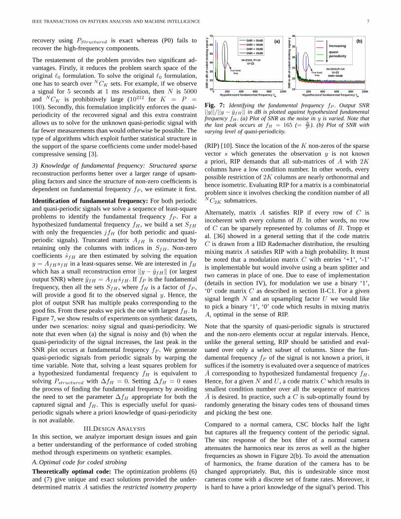
Identification of fundamental frequency: For both periodicand quasi-periodic signals we solve a sequence of least-squareproblems to identify the fundamental frequencyfP . For ahypothesized fundamental frequencyfH , we build a setSfH
with only the frequenciesjfH (for both periodic and quasi-periodic signals). Truncated matrixAfH is constructed byretaining only the columns with indices inSfH . Non-zerocoefficientssfH are then estimated by solving the equationy = AfHsfH in a least-squares sense. We are interested infHwhich has a small reconstruction error‖y − yfH‖ (or largestoutput SNR) whereyfH = AfH sfH . If fP is the fundamentalfrequency, then all the setsSfH , wherefH is a factor offP ,will provide a good fit to the observed signaly. Hence, theplot of output SNR has multiple peaks corresponding to thegood fits. From these peaks we pick the one with largestfH . InFigure 7, we show results of experiments on synthetic datasets,under two scenarios: noisy signal and quasi-periodicity. Wenote that even when (a) the signal is noisy and (b) when thequasi-periodicity of the signal increases, the last peak intheSNR plot occurs at fundamental frequencyfP . We generatequasi-periodic signals from periodic signals by warping thetime variable. Note that, solving a least squares problem fora hypothesized fundamental frequencyfH is equivalent tosolving Pstructured with ∆fH = 0. Setting∆fH = 0 easesthe process of finding the fundamental frequency by avoidingthe need to set the parameter∆fH appropriate for both thecaptured signal andfH . This is especially useful for quasi-periodic signals where a priori knowledge of quasi-periodicityis not available.
III.D ESIGN ANALYSIS
In this section, we analyze important design issues and gaina better understanding of the performance of coded strobingmethod through experiments on synthetic examples.
A. Optimal code for coded strobing
Theoretically optimal code: The optimization problems (6)and (7) give unique and exact solutions provided the under-determined matrixA satisfies therestricted isometry property
200 400 600 800 100015
20
25
30
35
40
Hypothesized fundamental frequency f H
SN
R in
dB
of c
oded
str
obin
g si
gnal
y
N=2310,P=14U=22
SNR=30dB
0 200 400 600 800 100010
20
30
40
50
60
70
Hypothesized fundamental frequency f H
SN
R in
dB
of c
oded
str
obin
g si
gnal
y
N=2310, P=14U=22
SNR = 50dBSNR = 40dB
SNR = 30dBSNR = 20dB
(a) (b)Increasing
quasi-periodicity
True fund.freq. True fund.
freq.
Fig. 7: Identifying the fundamental frequencyfP . Output SNR||y||/||y − yfH || in dB is plotted against hypothesized fundamentalfrequencyfH . (a) Plot of SNR as the noise iny is varied. Note thatthe last peak occurs atfH = 165 (= N
P). (b) Plot of SNR with
varying level of quasi-periodicity.
(RIP) [10]. Since the location of theK non-zeros of the sparsevector s which generates the observationy is not knowna priori, RIP demands that all sub-matrices ofA with 2Kcolumns have a low condition number. In other words, everypossible restriction of2K columns are nearly orthonormal andhence isometric. Evaluating RIP for a matrix is a combinatorialproblem since it involves checking the condition number of allNC2K submatrices.
Alternately, matrix A satisfies RIP if every row ofC isincoherent with every column ofB. In other words, no rowof C can be sparsely represented by columns ofB. Tropp etal. [36] showed in a general setting that if the code matrixC is drawn from a IID Rademacher distribution, the resultingmixing matrixA satisfies RIP with a high probability. It mustbe noted that a modulation matrixC with entries ‘+1’, ‘-1’is implementable but would involve using a beam splitter andtwo cameras in place of one. Due to ease of implementation(details in section IV), for modulation we use a binary ‘1’,‘0’ code matrixC as described in section II-C1. For a givensignal lengthN and an upsampling factorU we would liketo pick a binary ‘1’, ‘0’ code which results in mixing matrixA, optimal in the sense of RIP.
Note that the sparsity of quasi-periodic signals is structuredand the non-zero elements occur at regular intervals. Hence,unlike the general setting, RIP should be satisfied and eval-uated over only a select subset of columns. Since the fun-damental frequencyfP of the signal is not known a priori, itsuffices if the isometry is evaluated over a sequence of matricesA corresponding to hypothesized fundamental frequencyfH .Hence, for a givenN andU , a code matrixC which results insmallest condition number over all the sequence of matricesA is desired. In practice, such aC is sub-optimally found byrandomly generating the binary codes tens of thousand timesand picking the best one.
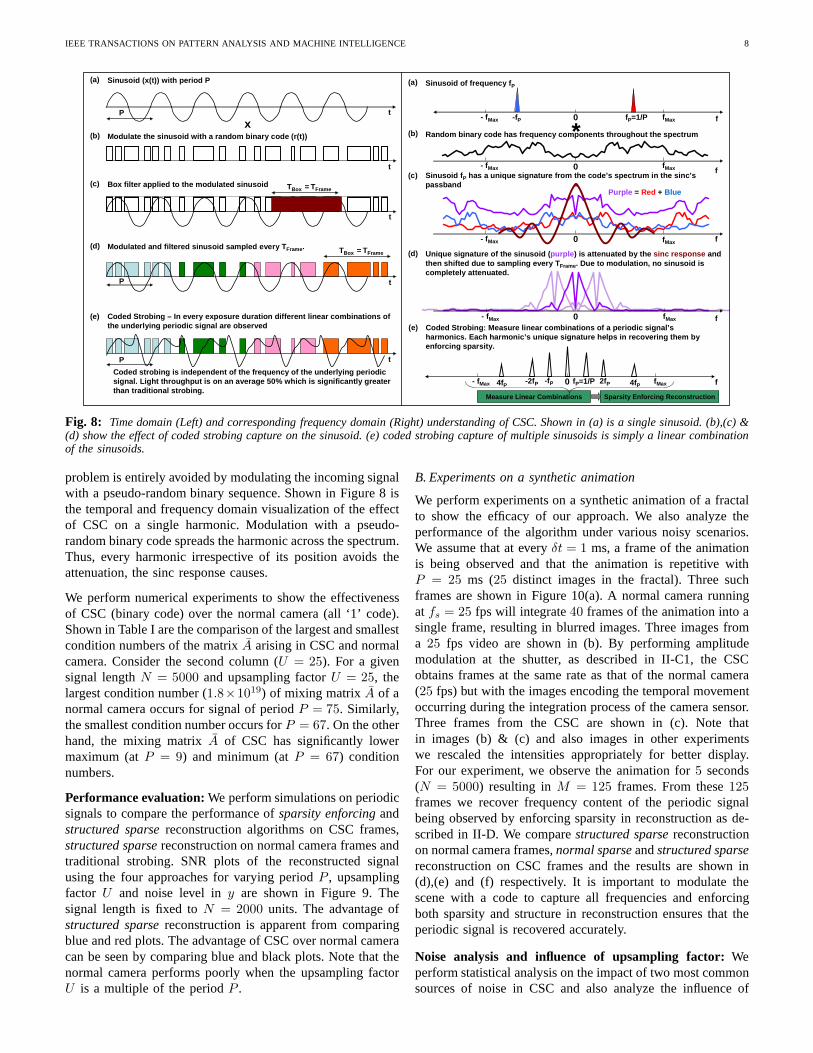
Compared to a normal camera, CSC blocks half the lightbut captures all the frequency content of the periodic signal.The sinc response of the box filter of a normal cameraattenuates the harmonics near its zeros as well as the higherfrequencies as shown in Figure 2(b). To avoid the attenuationof harmonics, the frame duration of the camera has to bechanged appropriately. But, this is undesirable since mostcameras come with a discrete set of frame rates. Moreover, itis hard to have a priori knowledge of the signal’s period. This
IEEE TRANSACTIONS ON PATTERN ANALYSIS AND MACHINE INTELLIGENCE 8
t
Sinusoid (x(t)) with period P
P
(a)
t
Coded Strobing – In every exposure duration differen t linear combinations of the underlying periodic signal are observed
P
(e)
Coded strobing is independent of the frequency of t he underlying periodic signal. Light throughput is on an average 50% which is significantly greater than traditional strobing.
tP
Modulate the sinusoid with a random binary code (r( t))(b)x
Box filter applied to the modulated sinusoid(c)
Modulated and filtered sinusoid sampled every T Frame. (d)
TBox = TFrame
t
TBox = TFrame
t
(a) Sinusoid of frequency f P
fP=1/P-fP 0
4fP
(e) Coded Strobing: Measure linear combinations of a pe riodic signal’s harmonics. Each harmonic’s unique signature helps i n recovering them by enforcing sparsity.
Measure Linear Combinations
0
*
0 fMax- fMax fP=1/P 2fP-fP-2fP4fP
fMax- fMax
fMax- fMax
0 fMax- fMax
0 fMax- fMax
(b) Random binary code has frequency components through out the spectrum
(c) Sinusoid f P has a unique signature from the code’s spectrum in the sinc’s passband
(d) Unique signature of the sinusoid ( purple ) is attenuated by the sinc response and then shifted due to sampling every T Frame. Due to modulation, no sinusoid is completely attenuated.
Sparsity Enforcing Reconstruction
f
f
f
f
f
Purple = Red + Blue
Fig. 8: Time domain (Left) and corresponding frequency domain (Right) understanding of CSC. Shown in (a) is a single sinusoid. (b),(c) &(d) show the effect of coded strobing capture on the sinusoid. (e) coded strobing capture of multiple sinusoids is simplya linear combinationof the sinusoids.
problem is entirely avoided by modulating the incoming signalwith a pseudo-random binary sequence. Shown in Figure 8 isthe temporal and frequency domain visualization of the effectof CSC on a single harmonic. Modulation with a pseudo-random binary code spreads the harmonic across the spectrum.Thus, every harmonic irrespective of its position avoids theattenuation, the sinc response causes.
We perform numerical experiments to show the effectivenessof CSC (binary code) over the normal camera (all ‘1’ code).Shown in Table I are the comparison of the largest and smallestcondition numbers of the matrixA arising in CSC and normalcamera. Consider the second column (U = 25). For a givensignal lengthN = 5000 and upsampling factorU = 25, thelargest condition number (1.8×10¹⁹) of mixing matrix A of anormal camera occurs for signal of periodP = 75. Similarly,the smallest condition number occurs forP = 67. On the otherhand, the mixing matrixA of CSC has significantly lowermaximum (atP = 9) and minimum (atP = 67) conditionnumbers.
Performance evaluation:We perform simulations on periodicsignals to compare the performance ofsparsity enforcingandstructured sparsereconstruction algorithms on CSC frames,structured sparsereconstruction on normal camera frames andtraditional strobing. SNR plots of the reconstructed signalusing the four approaches for varying periodP , upsamplingfactor U and noise level iny are shown in Figure 9. Thesignal length is fixed toN = 2000 units. The advantage ofstructured sparsereconstruction is apparent from comparingblue and red plots. The advantage of CSC over normal cameracan be seen by comparing blue and black plots. Note that thenormal camera performs poorly when the upsampling factorU is a multiple of the periodP .
B. Experiments on a synthetic animation
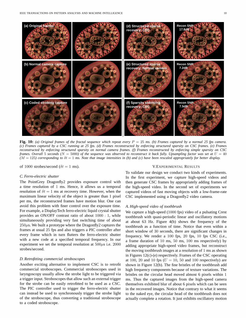
We perform experiments on a synthetic animation of a fractalto show the efficacy of our approach. We also analyze theperformance of the algorithm under various noisy scenarios.We assume that at everyδt = 1 ms, a frame of the animationis being observed and that the animation is repetitive withP = 25 ms (25 distinct images in the fractal). Three suchframes are shown in Figure 10(a). A normal camera runningat fs = 25 fps will integrate40 frames of the animation into asingle frame, resulting in blurred images. Three images froma 25 fps video are shown in (b). By performing amplitudemodulation at the shutter, as described in II-C1, the CSCobtains frames at the same rate as that of the normal camera(25 fps) but with the images encoding the temporal movementoccurring during the integration process of the camera sensor.Three frames from the CSC are shown in (c). Note thatin images (b) & (c) and also images in other experimentswe rescaled the intensities appropriately for better display.For our experiment, we observe the animation for5 seconds(N = 5000) resulting inM = 125 frames. From these125frames we recover frequency content of the periodic signalbeing observed by enforcing sparsity in reconstruction as de-scribed in II-D. We comparestructured sparsereconstructionon normal camera frames,normal sparseandstructured sparsereconstruction on CSC frames and the results are shown in(d),(e) and (f) respectively. It is important to modulate thescene with a code to capture all frequencies and enforcingboth sparsity and structure in reconstruction ensures thattheperiodic signal is recovered accurately.
Noise analysis and influence of upsampling factor:Weperform statistical analysis on the impact of two most commonsources of noise in CSC and also analyze the influence of
IEEE TRANSACTIONS ON PATTERN ANALYSIS AND MACHINE INTELLIGENCE 9
Condition Number κ / Period P U = 25 U = 40 U = 47 U = 55 U = 63 U = 91
NC: largest 1.8× 10¹⁹/75 8.6× 10
33/5 6.1× 1032/47 4.5× 10
65/95 3.4× 1064/90 6.5× 10
48/70CSC: largest 1.3× 10³/9 1.4× 10⁴/7 6.0× 10³/8 2.1× 10⁴/19 8.1× 10²/27 2.4× 10³/7NC: smallest 5.9× 10²/67 8.4× 10²/63 1.5× 10³/54 2.7× 10²/92 1.5× 10³/80 1.6× 10³/55CSC: smallest 16.5/67 11.5/94 10.1/98 9.7/90 10.9/77 13.2/53
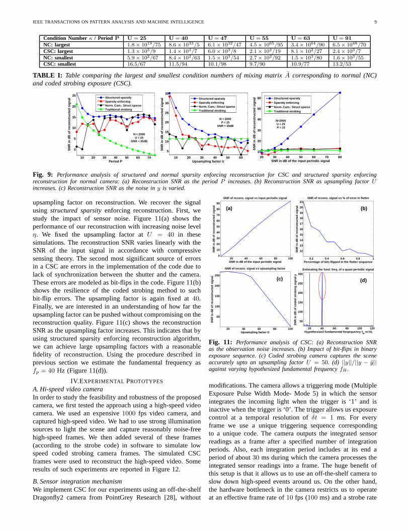
TABLE I: Table comparing the largest and smallest condition numbersof mixing matrixA corresponding to normal (NC)and coded strobing exposure (CSC).
10 20 30 40 50 60 70
0
5
10
15
20
25
Period P
SN
R in
dB
of r
econ
stru
cted
sig
nal
N = 2000U = 25
SNR = 35dB
Structured sparsitySparsity enforcingNorm. Cam.: Struct sparseTraditional strobing
10 20 30 40 50 60
5
10
15
20
25
30
35
Upsampling factor US
NR
in d
B o
f rec
onst
ruct
ed s
igna
l
N = 2000P = 15
SNR = 35dB
Structured sparsitySparsity enforcingNorm. Cam.: Struct sparseTraditional strobing
20 30 40 50 60 70 80
10
20
30
40
50
60
SNR in dB of the input periodic signal
SN
R in
dB
of r
econ
stru
cted
sig
nal
N=2000U = 25P = 15
Structured sparsity
Sparsity enforcing
Norm. Cam.: Struct sparse
Traditional strobing
Fig. 9: Performance analysis of structured and normal sparsity enforcing reconstruction for CSC and structured sparsity enforcingreconstruction for normal camera: (a) Reconstruction SNR as the periodP increases. (b) Reconstruction SNR as upsampling factorUincreases. (c) Reconstruction SNR as the noise iny is varied.
upsampling factor on reconstruction. We recover the signalusing structured sparsityenforcing reconstruction. First, westudy the impact of sensor noise. Figure 11(a) shows theperformance of our reconstruction with increasing noise levelη. We fixed the upsampling factor atU = 40 in thesesimulations. The reconstruction SNR varies linearly with theSNR of the input signal in accordance with compressivesensing theory. The second most significant source of errorsin a CSC are errors in the implementation of the code due tolack of synchronization between the shutter and the camera.These errors are modeled as bit-flips in the code. Figure 11(b)shows the resilience of the coded strobing method to suchbit-flip errors. The upsampling factor is again fixed at40.Finally, we are interested in an understanding of how far theupsampling factor can be pushed without compromising on thereconstruction quality. Figure 11(c) shows the reconstructionSNR as the upsampling factor increases. This indicates thatbyusing structured sparsity enforcing reconstruction algorithm,we can achieve large upsampling factors with a reasonablefidelity of reconstruction. Using the procedure described inprevious section we estimate the fundamental frequency asfp = 40 Hz (Figure 11(d)).
IV.EXPERIMENTAL PROTOTYPES
A. Hi-speed video cameraIn order to study the feasibility and robustness of the proposedcamera, we first tested the approach using a high-speed videocamera. We used an expensive1000 fps video camera, andcaptured high-speed video. We had to use strong illuminationsources to light the scene and capture reasonably noise-freehigh-speed frames. We then added several of these frames(according to the strobe code) in software to simulate lowspeed coded strobing camera frames. The simulated CSCframes were used to reconstruct the high-speed video. Someresults of such experiments are reported in Figure 12.
B. Sensor integration mechanismWe implement CSC for our experiments using an off-the-shelfDragonfly2 camera from PointGrey Research [28], without
20 40 60 80 1000
10
20
30
40
50
60
70
80
90
SNR in dB of the input periodic signal
SN
R in
dB
of r
econ
stru
cted
sig
nal
SNR of recons. signal vs input periodic signal
(a)
0.2 0.4 0.6 0.8 1
12
13
14
15
16
17
18
19
20
21
Percentage of bits flipped in the flutter sequence
SN
R in
dB
of r
econ
stru
cted
sig
nal
SNR of recons. signal vs % of error in flutter
(b)
20 40 60 80 100 120
50
100
150
200
250
300
Hypothesized fundamental freqequency fH
in Hz
SN
R in
dB
of c
oded
str
obin
g si
gnal
y
Estimating the fund. freq. of a quasi-periodic sign al
(d)
20 40 60 80 100
50
100
150
200
250
Upsampling factor U
SN
R in
dB
of r
econ
stru
cted
sig
nal
SNR of recons. signal vs upsampling factor
(c)
Fig. 11: Performance analysis of CSC: (a) Reconstruction SNRas the observation noise increases. (b) Impact of bit-flips in binaryexposure sequence. (c) Coded strobing camera captures the sceneaccurately upto an upsampling factorU = 50. (d) ||y||/||y − y||against varying hypothesized fundamental frequencyfH .
modifications. The camera allows a triggering mode (MultipleExposure Pulse Width Mode- Mode 5) in which the sensorintegrates the incoming light when the trigger is ‘1’ and isinactive when the trigger is ‘0’. The trigger allows us exposurecontrol at a temporal resolution ofδt = 1 ms. For everyframe we use a unique triggering sequence correspondingto a unique code. The camera outputs the integrated sensorreadings as a frame after a specified number of integrationperiods. Also, each integration period includes at its end aperiod of about30 ms during which the camera processes theintegrated sensor readings into a frame. The huge benefit ofthis setup is that it allows us to use an off-the-shelf cameratoslow down high-speed events around us. On the other hand,the hardware bottleneck in the camera restricts us to operateat an effective frame rate of10 fps (100 ms) and a strobe rate
IEEE TRANSACTIONS ON PATTERN ANALYSIS AND MACHINE INTELLIGENCE 10
(a) Original frames
(b) Normal camera capture
(c) Coded strobing capture
Recon SNR17.8dB
(d) Structured sparse recovery: CSC
Recon SNR7.2dB
(e) Structured sparse recovery: Normal camera
Recon SNR7.5dB
(f) Sparsity enforcingrecovery: CSC
Fig. 10: (a) Original frames of the fractal sequence which repeat every P = 25 ms. (b) Frames captured by a normal 25 fps camera.(c) Frames captured by a CSC running at 25 fps. (d) Frames reconstructed by enforcing structured sparsity on CSC frames. (e) Framesreconstructed by enforcing structured sparsity on normal camera frames. (f) Frames reconstructed by enforcing simplesparsity on CSCframes. Overall5 seconds (N = 5000) of the sequence was observed to reconstruct it back fully. Upsampling factor was set atU = 40
(M = 125) corresponding toδt = 1 ms. Note that image intensities in (b) and (c) have been rescaled appropriately for better display.
of 1000 strobes/second (δt = 1 ms).
C. Ferro-electric shutter
The PointGrey Dragonfly2 provides exposure control witha time resolution of1 ms. Hence, it allows us a temporalresolution ofδt = 1 ms at recovery time. However, when themaximum linear velocity of the object is greater than 1 pixelper ms, the reconstructed frames have motion blur. One canavoid this problem with finer control over the exposure time.For example, a DisplayTech ferro-electric liquid crystal shutterprovides an ON/OFF contrast ratio of about1000 : 1, whilesimultaneously providing very fast switching time of about250µs. We built a prototype where the Dragonfly2 captures theframes at usual25 fps and also triggers a PIC controller afterevery frame which in turn flutters the ferro-electric shutterwith a new code at a specified temporal frequency. In ourexperiment we set the temporal resolution at500µs i.e.2000strobes/second.
D. Retrofitting commercial stroboscopes
Another exciting alternative to implement CSC is to retrofitcommercial stroboscopes. Commercial stroboscopes used inlaryngoscopy usually allow the strobe light to be triggeredviaa trigger input. Stroboscopes that allow such an external triggerfor the strobe can be easily retrofitted to be used as a CSC.The PIC controller used to trigger the ferro-electric shuttercan instead be used to synchronously trigger the strobe lightof the stroboscope, thus converting a traditional stroboscopeto a coded stroboscope.
V.EXPERIMENTAL RESULTS
To validate our design we conduct two kinds of experiments.In the first experiment, we capture high-speed videos andthen generate CSC frames by appropriately adding frames ofthe high-speed video. In the second set of experiments wecaptured videos of fast moving objects with a low-frame-rateCSC implemented using a Dragonfly2 video camera.
A. High-speed video of toothbrush
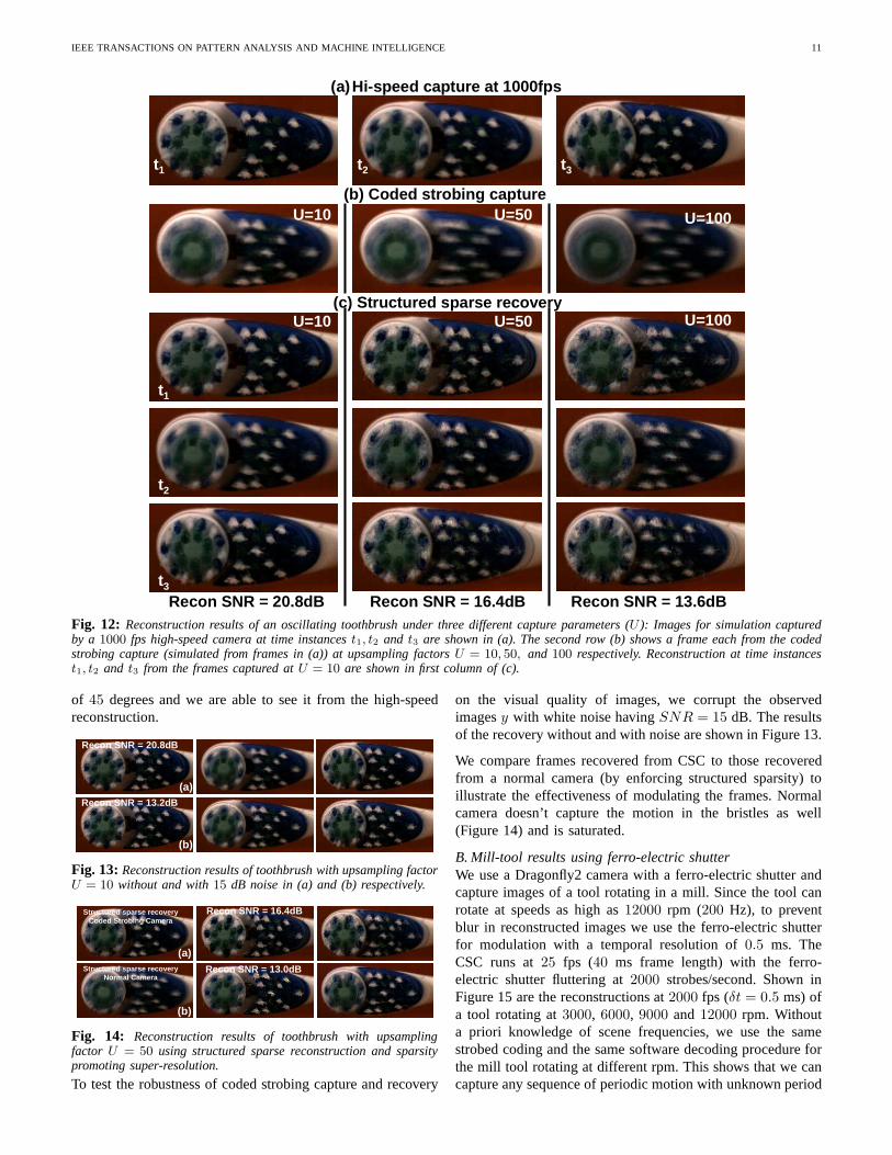
We capture a high-speed (1000 fps) video of a pulsating Cresttoothbrush with quasi-periodic linear and oscillatory motionsat about 63 Hz. Figure 4(b) shows the frequency of thetoothbrush as a function of time. Notice that even within ashort window of30 seconds, there are significant changes infrequency. We render a100 fps, 20 fps, 10 fps CSC (i.e.,a frame duration of10 ms, 50 ms, 100 ms respectively) byadding appropriate high-speed video frames, but reconstructthe moving toothbrush images at a resolution of1 ms as shownin Figures 12(c)-(e) respectively. Frames of the CSC operatingat 100, 20 and10 fps (U = 10, 50 and100 respectively) areshown in Figure 12(b). The fine bristles of the toothbrush addhigh frequency components because of texture variations. Thebristles on the circular head moved almost 6 pixels within1ms. Thus the captured images from the high-speed camerathemselves exhibited blur of about 6 pixels which can be seenin the recovered images. Notice that contrary to what it seemsto the naked eye, the circular head of the toothbrush does notactually complete a rotation. It just exhibits oscillatorymotion
IEEE TRANSACTIONS ON PATTERN ANALYSIS AND MACHINE INTELLIGENCE 11
(a)Hi-speed capture at 1000fps
(b)(b) Coded strobing capture
U=10 U=50 U=100
Recon SNR = 20.8dB Recon SNR = 16.4dB Recon SNR = 13. 6dB
(c) Structured sparse recoveryU=10 U=50 U=100
t1 t3t2
t1
t2
t3
Fig. 12: Reconstruction results of an oscillating toothbrush underthree different capture parameters (U ): Images for simulation capturedby a 1000 fps high-speed camera at time instancest1, t2 and t3 are shown in (a). The second row (b) shows a frame each from thecodedstrobing capture (simulated from frames in (a)) at upsampling factorsU = 10, 50, and 100 respectively. Reconstruction at time instancest1, t2 and t3 from the frames captured atU = 10 are shown in first column of (c).
of 45 degrees and we are able to see it from the high-speedreconstruction.
(b)
(a)
Recon SNR = 20.8dB
Recon SNR = 13.2dB
Fig. 13: Reconstruction results of toothbrush with upsampling factorU = 10 without and with15 dB noise in (a) and (b) respectively.
(b)
(a)
Recon SNR = 16.4dB
Recon SNR = 13.0dB
Structured sparse recoveryCoded Strobing Camera
Structured sparse recoveryNormal Camera
Fig. 14: Reconstruction results of toothbrush with upsamplingfactor U = 50 using structured sparse reconstruction and sparsitypromoting super-resolution.
To test the robustness of coded strobing capture and recovery
on the visual quality of images, we corrupt the observedimagesy with white noise havingSNR = 15 dB. The resultsof the recovery without and with noise are shown in Figure 13.
We compare frames recovered from CSC to those recoveredfrom a normal camera (by enforcing structured sparsity) toillustrate the effectiveness of modulating the frames. Normalcamera doesn’t capture the motion in the bristles as well(Figure 14) and is saturated.
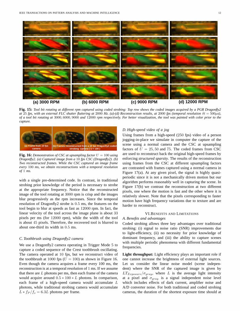
B. Mill-tool results using ferro-electric shutterWe use a Dragonfly2 camera with a ferro-electric shutter andcapture images of a tool rotating in a mill. Since the tool canrotate at speeds as high as12000 rpm (200 Hz), to preventblur in reconstructed images we use the ferro-electric shutterfor modulation with a temporal resolution of0.5 ms. TheCSC runs at25 fps (40 ms frame length) with the ferro-electric shutter fluttering at2000 strobes/second. Shown inFigure 15 are the reconstructions at2000 fps (δt = 0.5 ms) ofa tool rotating at3000, 6000, 9000 and 12000 rpm. Withouta priori knowledge of scene frequencies, we use the samestrobed coding and the same software decoding procedure forthe mill tool rotating at different rpm. This shows that we cancapture any sequence of periodic motion with unknown period
IEEE TRANSACTIONS ON PATTERN ANALYSIS AND MACHINE INTELLIGENCE 12
(a) 3000 RPM (b) 6000 RPM (c) 9000 RPM (d) 12000 RPM
Fig. 15: Tool bit rotating at different rpm captured using coded strobing: Top row shows the coded images acquired by a PGR Dragonfly2at 25 fps, with an external FLC shutter fluttering at2000 Hz. (a)-(d) Reconstruction results, at2000 fps (temporal resolutionδt = 500µs),of a tool bit rotating at3000, 6000, 9000 and 12000 rpm respectively. For better visualization, the tool was painted with color prior to thecapture.
(a) Frame from 10 fps camera
(b) Frames reconstructed from a 10 fps Dragonfly2 c oded strobing camera ( U = 100 )
Fig. 16: Demonstration of CSC at upsampling factorU = 100 usingDragonfly2. (a) Captured image from a10 fps CSC (Dragonfly2). (b)Two reconstructed frames. While the CSC captured an image frameevery100 ms, we obtain reconstructions with a temporal resolutionof 1 ms.
with a single pre-determined code. In contrast, in traditionalstrobing prior knowledge of the period is necessary to strobeat the appropriate frequency. Notice that the reconstructedimage of the tool rotating at3000 rpm is crisp and the imagesblur progressively as the rpm increases. Since the temporalresolution of Dragonfly2 strobe is0.5 ms, the features on thetool begin to blur at speeds as fast as12000 rpm. In fact, thelinear velocity of the tool across the image plane is about33pixels per ms (for12000 rpm), while the width of the toolis about45 pixels. Therefore, the recovered tool is blurred toabout one-third its width in0.5 ms.
C. Toothbrush using Dragonfly2 camera
We use a Dragonfly2 camera operating in Trigger Mode 5 tocapture a coded sequence of the Crest toothbrush oscillating.The camera operated at10 fps, but we reconstruct video ofthe toothbrush at1000 fps (U = 100) as shown in Figure 16.Even though the camera acquires a frame every 100 ms, thereconstruction is at a temporal resolution of1 ms. If we assumethat there areL photons per ms, then each frame of the camerawould acquire around0.5 ∗ 100 ∗ L photons. In comparison,each frame of a high-speed camera would accumulateLphotons, while traditional strobing camera would accumulateL ∗ fP /fs = 6.3L photons per frame.
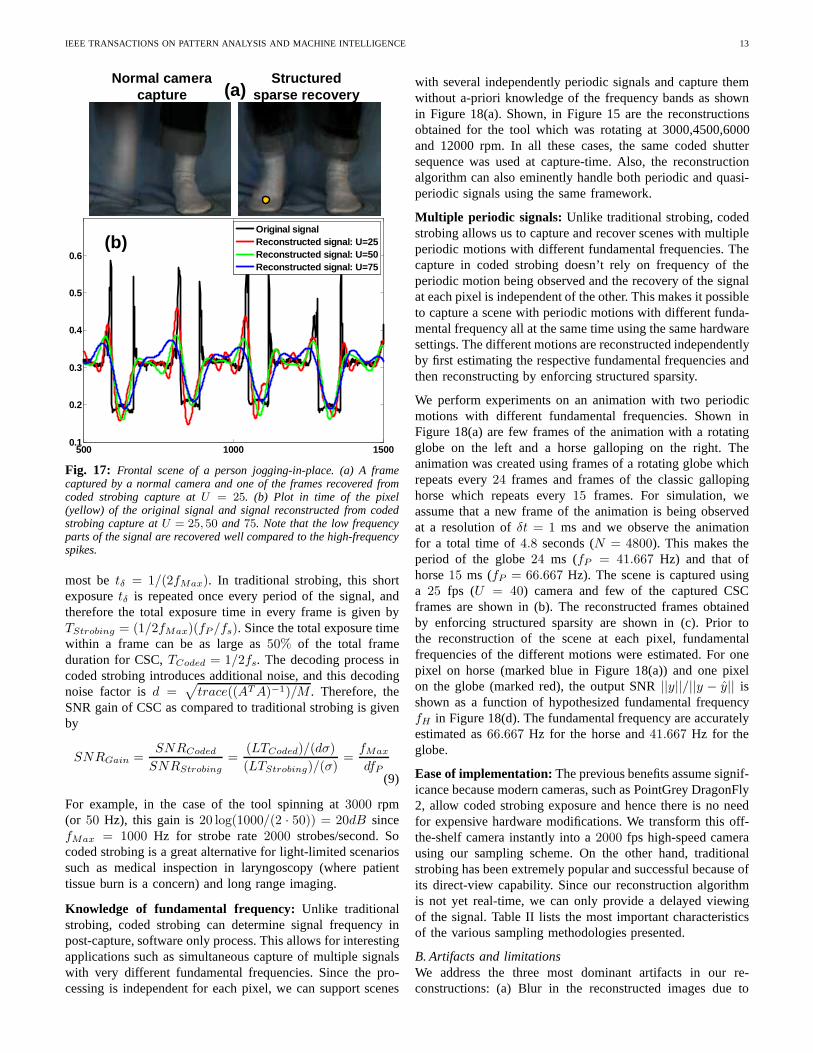
D. High-speed video of a jogUsing frames from a high-speed (250 fps) video of a personjogging-in-place we simulate in computer the capture of thescene using a normal camera and the CSC at upsamplingfactors ofU = 25, 50 and75. The coded frames from CSCare used to reconstruct back the original high-speed framesbyenforcingstructured sparsity. The results of the reconstructionusing frames from the CSC at different upsampling factorsare contrasted with frames captured using a normal camera inFigure 17(a). At any given pixel, the signal is highly quasi-periodic since it is not a mechanically driven motion but ouralgorithm performs reasonably well in capturing the scene.InFigure 17(b) we contrast the reconstruction at two differentpixels, one where the motion is fast and the other where it isrelatively slower. Note that the pixels corresponding to fastermotion have high frequency variations due to texture and areharder to reconstruct.
VI.B ENEFITS AND L IMITATIONS
A. Benefits and advantagesCoded strobing allows three key advantages over traditionalstrobing: (i) signal to noise ratio (SNR) improvements dueto light-efficiency, (ii) no necessity for prior knowledge ofdominant frequency, and (iii) the ability to capture sceneswith multiple periodic phenomena with different fundamentalfrequencies.
Light throughput: Light efficiency plays an important role ifone cannot increase the brightness of external light sources.Let us consider the linear noise model (scene indepen-dent) where the SNR of the captured image is given byLTExposure/σgray, where L is the average light intensityat a pixel andσgray is a signal independent noise levelwhich includes effects of dark current, amplifier noise andA/D converter noise. For both traditional and coded strobingcameras, the duration of the shortest exposure time should at
IEEE TRANSACTIONS ON PATTERN ANALYSIS AND MACHINE INTELLIGENCE 13
500 1000 15000.1
0.2
0.3
0.4
0.5
0.6
Original signalReconstructed signal: U=25Reconstructed signal: U=50Reconstructed signal: U=75
Normal camera capture
Structured sparse recovery(a)
(b)
Fig. 17: Frontal scene of a person jogging-in-place. (a) A framecaptured by a normal camera and one of the frames recovered fromcoded strobing capture atU = 25. (b) Plot in time of the pixel(yellow) of the original signal and signal reconstructed from codedstrobing capture atU = 25, 50 and 75. Note that the low frequencyparts of the signal are recovered well compared to the high-frequencyspikes.
most betδ = 1/(2fMax). In traditional strobing, this shortexposuretδ is repeated once every period of the signal, andtherefore the total exposure time in every frame is given byTStrobing = (1/2fMax)(fP /fs). Since the total exposure timewithin a frame can be as large as50% of the total frameduration for CSC,TCoded = 1/2fs. The decoding process incoded strobing introduces additional noise, and this decodingnoise factor isd =
√
trace((ATA)−1)/M . Therefore, theSNR gain of CSC as compared to traditional strobing is givenby
SNRGain =SNRCoded
SNRStrobing
=(LTCoded)/(dσ)
(LTStrobing)/(σ)=
fMax
dfP(9)
For example, in the case of the tool spinning at3000 rpm(or 50 Hz), this gain is20 log(1000/(2 · 50)) = 20dB sincefMax = 1000 Hz for strobe rate2000 strobes/second. Socoded strobing is a great alternative for light-limited scenariossuch as medical inspection in laryngoscopy (where patienttissue burn is a concern) and long range imaging.
Knowledge of fundamental frequency: Unlike traditionalstrobing, coded strobing can determine signal frequency inpost-capture, software only process. This allows for interestingapplications such as simultaneous capture of multiple signalswith very different fundamental frequencies. Since the pro-cessing is independent for each pixel, we can support scenes
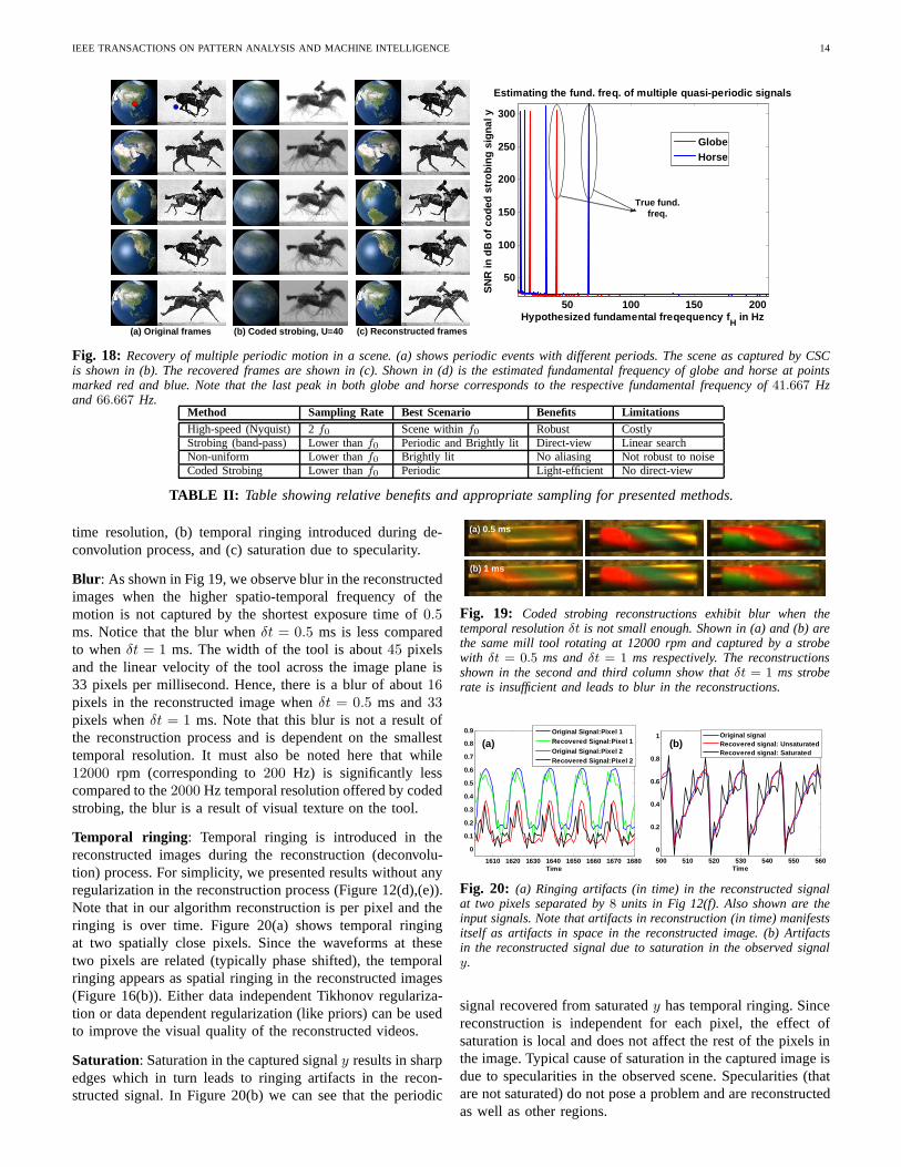
with several independently periodic signals and capture themwithout a-priori knowledge of the frequency bands as shownin Figure 18(a). Shown, in Figure 15 are the reconstructionsobtained for the tool which was rotating at 3000,4500,6000and 12000 rpm. In all these cases, the same coded shuttersequence was used at capture-time. Also, the reconstructionalgorithm can also eminently handle both periodic and quasi-periodic signals using the same framework.
Multiple periodic signals: Unlike traditional strobing, codedstrobing allows us to capture and recover scenes with multipleperiodic motions with different fundamental frequencies.Thecapture in coded strobing doesn’t rely on frequency of theperiodic motion being observed and the recovery of the signalat each pixel is independent of the other. This makes it possibleto capture a scene with periodic motions with different funda-mental frequency all at the same time using the same hardwaresettings. The different motions are reconstructed independentlyby first estimating the respective fundamental frequenciesandthen reconstructing by enforcing structured sparsity.
We perform experiments on an animation with two periodicmotions with different fundamental frequencies. Shown inFigure 18(a) are few frames of the animation with a rotatingglobe on the left and a horse galloping on the right. Theanimation was created using frames of a rotating globe whichrepeats every24 frames and frames of the classic gallopinghorse which repeats every15 frames. For simulation, weassume that a new frame of the animation is being observedat a resolution ofδt = 1 ms and we observe the animationfor a total time of4.8 seconds (N = 4800). This makes theperiod of the globe24 ms (fP = 41.667 Hz) and that ofhorse15 ms (fP = 66.667 Hz). The scene is captured usinga 25 fps (U = 40) camera and few of the captured CSCframes are shown in (b). The reconstructed frames obtainedby enforcing structured sparsity are shown in (c). Prior tothe reconstruction of the scene at each pixel, fundamentalfrequencies of the different motions were estimated. For onepixel on horse (marked blue in Figure 18(a)) and one pixelon the globe (marked red), the output SNR||y||/||y − y|| isshown as a function of hypothesized fundamental frequencyfH in Figure 18(d). The fundamental frequency are accuratelyestimated as66.667 Hz for the horse and41.667 Hz for theglobe.
Ease of implementation:The previous benefits assume signif-icance because modern cameras, such as PointGrey DragonFly2, allow coded strobing exposure and hence there is no needfor expensive hardware modifications. We transform this off-the-shelf camera instantly into a2000 fps high-speed camerausing our sampling scheme. On the other hand, traditionalstrobing has been extremely popular and successful becauseofits direct-view capability. Since our reconstruction algorithmis not yet real-time, we can only provide a delayed viewingof the signal. Table II lists the most important characteristicsof the various sampling methodologies presented.
B. Artifacts and limitationsWe address the three most dominant artifacts in our re-constructions: (a) Blur in the reconstructed images due to
IEEE TRANSACTIONS ON PATTERN ANALYSIS AND MACHINE INTELLIGENCE 14
(a) Original frames (b) Coded strobing, U=40 (c) Reconstructed frames
50 100 150 200
50
100
150
200
250
300
Hypothesized fundamental freqequency fH
in Hz
SN
R in
dB
of c
oded
str
obin
g si
gnal
y
Estimating the fund. freq. of multiple quasi-period ic signals
GlobeHorse
True fund.freq.
Fig. 18: Recovery of multiple periodic motion in a scene. (a) shows periodic events with different periods. The scene as capturedby CSCis shown in (b). The recovered frames are shown in (c). Shown in (d) is the estimated fundamental frequency of globe and horse at pointsmarked red and blue. Note that the last peak in both globe and horse corresponds to the respective fundamental frequency of 41.667 Hzand 66.667 Hz.
Method Sampling Rate Best Scenario Benefits LimitationsHigh-speed (Nyquist) 2 f0 Scene withinf0 Robust CostlyStrobing (band-pass) Lower thanf0 Periodic and Brightly lit Direct-view Linear searchNon-uniform Lower thanf0 Brightly lit No aliasing Not robust to noiseCoded Strobing Lower thanf0 Periodic Light-efficient No direct-view
TABLE II: Table showing relative benefits and appropriate sampling for presented methods.
time resolution, (b) temporal ringing introduced during de-convolution process, and (c) saturation due to specularity.
Blur : As shown in Fig 19, we observe blur in the reconstructedimages when the higher spatio-temporal frequency of themotion is not captured by the shortest exposure time of0.5ms. Notice that the blur whenδt = 0.5 ms is less comparedto whenδt = 1 ms. The width of the tool is about45 pixelsand the linear velocity of the tool across the image plane is33 pixels per millisecond. Hence, there is a blur of about16pixels in the reconstructed image whenδt = 0.5 ms and33pixels whenδt = 1 ms. Note that this blur is not a result ofthe reconstruction process and is dependent on the smallesttemporal resolution. It must also be noted here that while12000 rpm (corresponding to200 Hz) is significantly lesscompared to the2000 Hz temporal resolution offered by codedstrobing, the blur is a result of visual texture on the tool.
Temporal ringing : Temporal ringing is introduced in thereconstructed images during the reconstruction (deconvolu-tion) process. For simplicity, we presented results without anyregularization in the reconstruction process (Figure 12(d),(e)).Note that in our algorithm reconstruction is per pixel and theringing is over time. Figure 20(a) shows temporal ringingat two spatially close pixels. Since the waveforms at thesetwo pixels are related (typically phase shifted), the temporalringing appears as spatial ringing in the reconstructed images(Figure 16(b)). Either data independent Tikhonov regulariza-tion or data dependent regularization (like priors) can be usedto improve the visual quality of the reconstructed videos.
Saturation: Saturation in the captured signaly results in sharpedges which in turn leads to ringing artifacts in the recon-structed signal. In Figure 20(b) we can see that the periodic
(a) 0.5 ms
(b) 1 ms
Fig. 19: Coded strobing reconstructions exhibit blur when thetemporal resolutionδt is not small enough. Shown in (a) and (b) arethe same mill tool rotating at 12000 rpm and captured by a strobewith δt = 0.5 ms andδt = 1 ms respectively. The reconstructionsshown in the second and third column show thatδt = 1 ms stroberate is insufficient and leads to blur in the reconstructions.
1610 1620 1630 1640 1650 1660 1670 1680
0
0.1
0.2
0.3
0.4
0.5
0.6
0.7
0.8
0.9
Time
Original Signal:Pixel 1Recovered Signal:Pixel 1
Original Signal:Pixel 2Recovered Signal:Pixel 2
500 510 520 530 540 550 560
0
0.2
0.4
0.6
0.8
1
Time
Original signalRecovered signal: UnsaturatedRecovered signal: Saturated
(a) (b)
Fig. 20: (a) Ringing artifacts (in time) in the reconstructed signalat two pixels separated by8 units in Fig 12(f). Also shown are theinput signals. Note that artifacts in reconstruction (in time) manifestsitself as artifacts in space in the reconstructed image. (b)Artifactsin the reconstructed signal due to saturation in the observed signaly.
signal recovered from saturatedy has temporal ringing. Sincereconstruction is independent for each pixel, the effect ofsaturation is local and does not affect the rest of the pixelsinthe image. Typical cause of saturation in the captured imageisdue to specularities in the observed scene. Specularities (thatare not saturated) do not pose a problem and are reconstructedas well as other regions.
IEEE TRANSACTIONS ON PATTERN ANALYSIS AND MACHINE INTELLIGENCE 15
1610 1620 1630 1640 1650 1660 1670 1680
0.2
0.4
0.6
0.8
1
Time
Signal 11Signal 13Signal 31Signal 33
Fig. 21: The waveforms in a neighborhood are highly similar andhence the information is redundant. Shown are the waveformsof 4pixels at the corners of a3 × 3 neighborhood. The waveforms aredisplaced vertically for better visualization.
VII.E XTENSIONS AND CONCLUSIONS
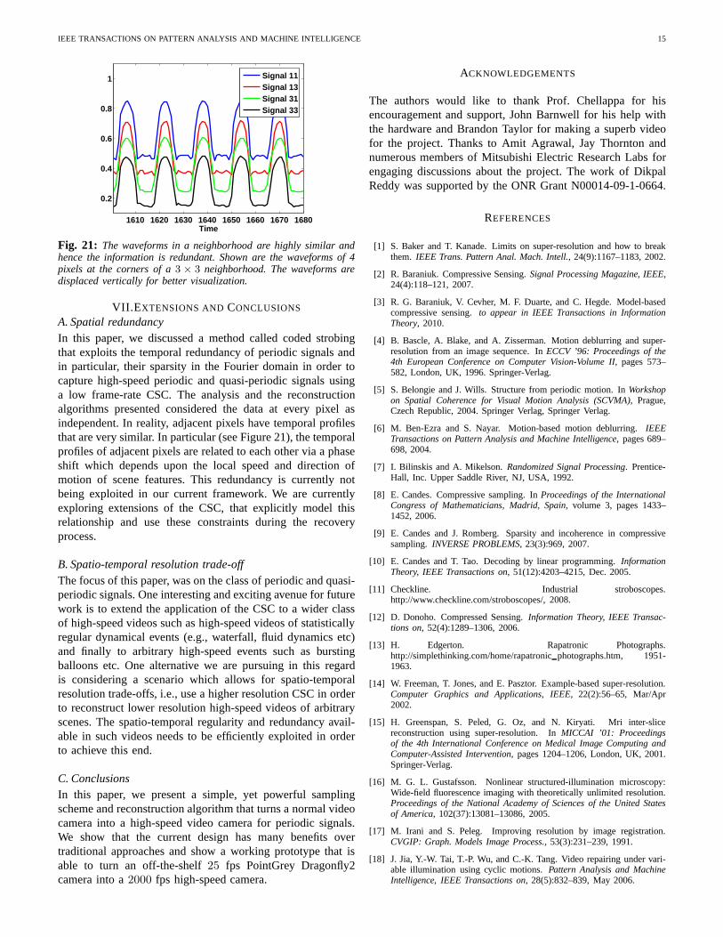
A. Spatial redundancyIn this paper, we discussed a method called coded strobingthat exploits the temporal redundancy of periodic signals andin particular, their sparsity in the Fourier domain in ordertocapture high-speed periodic and quasi-periodic signals usinga low frame-rate CSC. The analysis and the reconstructionalgorithms presented considered the data at every pixel asindependent. In reality, adjacent pixels have temporal profilesthat are very similar. In particular (see Figure 21), the temporalprofiles of adjacent pixels are related to each other via a phaseshift which depends upon the local speed and direction ofmotion of scene features. This redundancy is currently notbeing exploited in our current framework. We are currentlyexploring extensions of the CSC, that explicitly model thisrelationship and use these constraints during the recoveryprocess.
B. Spatio-temporal resolution trade-offThe focus of this paper, was on the class of periodic and quasi-periodic signals. One interesting and exciting avenue for futurework is to extend the application of the CSC to a wider classof high-speed videos such as high-speed videos of statisticallyregular dynamical events (e.g., waterfall, fluid dynamics etc)and finally to arbitrary high-speed events such as burstingballoons etc. One alternative we are pursuing in this regardis considering a scenario which allows for spatio-temporalresolution trade-offs, i.e., use a higher resolution CSC inorderto reconstruct lower resolution high-speed videos of arbitraryscenes. The spatio-temporal regularity and redundancy avail-able in such videos needs to be efficiently exploited in orderto achieve this end.
C. ConclusionsIn this paper, we present a simple, yet powerful samplingscheme and reconstruction algorithm that turns a normal videocamera into a high-speed video camera for periodic signals.We show that the current design has many benefits overtraditional approaches and show a working prototype that isable to turn an off-the-shelf25 fps PointGrey Dragonfly2camera into a2000 fps high-speed camera.
ACKNOWLEDGEMENTS
The authors would like to thank Prof. Chellappa for hisencouragement and support, John Barnwell for his help withthe hardware and Brandon Taylor for making a superb videofor the project. Thanks to Amit Agrawal, Jay Thornton andnumerous members of Mitsubishi Electric Research Labs forengaging discussions about the project. The work of DikpalReddy was supported by the ONR Grant N00014-09-1-0664.
REFERENCES
[1] S. Baker and T. Kanade. Limits on super-resolution and how to breakthem. IEEE Trans. Pattern Anal. Mach. Intell., 24(9):1167–1183, 2002.
[2] R. Baraniuk. Compressive Sensing.Signal Processing Magazine, IEEE,24(4):118–121, 2007.
[3] R. G. Baraniuk, V. Cevher, M. F. Duarte, and C. Hegde. Model-basedcompressive sensing.to appear in IEEE Transactions in InformationTheory, 2010.
[4] B. Bascle, A. Blake, and A. Zisserman. Motion deblurringand super-resolution from an image sequence. InECCV ’96: Proceedings of the4th European Conference on Computer Vision-Volume II, pages 573–582, London, UK, 1996. Springer-Verlag.
[5] S. Belongie and J. Wills. Structure from periodic motion. In Workshopon Spatial Coherence for Visual Motion Analysis (SCVMA), Prague,Czech Republic, 2004. Springer Verlag, Springer Verlag.
[6] M. Ben-Ezra and S. Nayar. Motion-based motion deblurring. IEEETransactions on Pattern Analysis and Machine Intelligence, pages 689–698, 2004.
[7] I. Bilinskis and A. Mikelson.Randomized Signal Processing. Prentice-Hall, Inc. Upper Saddle River, NJ, USA, 1992.
[8] E. Candes. Compressive sampling. InProceedings of the InternationalCongress of Mathematicians, Madrid, Spain, volume 3, pages 1433–1452, 2006.
[9] E. Candes and J. Romberg. Sparsity and incoherence in compressivesampling. INVERSE PROBLEMS, 23(3):969, 2007.
[10] E. Candes and T. Tao. Decoding by linear programming.InformationTheory, IEEE Transactions on, 51(12):4203–4215, Dec. 2005.
[11] Checkline. Industrial stroboscopes.http://www.checkline.com/stroboscopes/, 2008.
[12] D. Donoho. Compressed Sensing.Information Theory, IEEE Transac-tions on, 52(4):1289–1306, 2006.
[13] H. Edgerton. Rapatronic Photographs.http://simplethinking.com/home/rapatronicphotographs.htm, 1951-1963.
[14] W. Freeman, T. Jones, and E. Pasztor. Example-based super-resolution.Computer Graphics and Applications, IEEE, 22(2):56–65, Mar/Apr2002.
[15] H. Greenspan, S. Peled, G. Oz, and N. Kiryati. Mri inter-slicereconstruction using super-resolution. InMICCAI ’01: Proceedingsof the 4th International Conference on Medical Image Computing andComputer-Assisted Intervention, pages 1204–1206, London, UK, 2001.Springer-Verlag.
[16] M. G. L. Gustafsson. Nonlinear structured-illumination microscopy:Wide-field fluorescence imaging with theoretically unlimited resolution.Proceedings of the National Academy of Sciences of the United Statesof America, 102(37):13081–13086, 2005.
[17] M. Irani and S. Peleg. Improving resolution by image registration.CVGIP: Graph. Models Image Process., 53(3):231–239, 1991.
[18] J. Jia, Y.-W. Tai, T.-P. Wu, and C.-K. Tang. Video repairing under vari-able illumination using cyclic motions.Pattern Analysis and MachineIntelligence, IEEE Transactions on, 28(5):832–839, May 2006.
IEEE TRANSACTIONS ON PATTERN ANALYSIS AND MACHINE INTELLIGENCE 16
[19] I. Laptev, S. J. Belongie, P. Perez, and J. Wills. Periodic motion detectionand segmentation via approximate sequence alignment. InICCV ’05:Proceedings of the Tenth IEEE International Conference on ComputerVision (ICCV’05) Volume 1, pages 816–823, Washington, DC, USA,2005. IEEE Computer Society.
[20] H. Larsson, S. Hertegard, and B. Hammarberg. Vocal Fold Vibrations:High-Speed Imaging, Kymography, and Acoustic Analysis: A Prelimi-nary Report.The Laryngoscope, 110(12):2117, 2000.
[21] A. Levin, P. Sand, T. Cho, F. Durand, and W. Freeman. Motion-invariantphotography. InProc. ACM SIGGRAPH, volume 8, 2008.
[22] Z. Lin and H.-Y. Shum. Fundamental limits of reconstruction-basedsuperresolution algorithms under local translation.IEEE Trans. PatternAnal. Mach. Intell., 26(1):83–97, 2004.
[23] F. Marvasti. Nonuniform Sampling: Theory and Practice. KluwerAcademic/Plenum Publishers, 2001.
[24] P. Mergell, H. Herzel, and I. Titze. Irregular vocal-fold vibrationHigh-speed observation and modeling.The Journal of the Acoustical Societyof America, 108:2996, 2000.
[25] E. Muybridge.Animals in Motion. Dover Publications, 1957. First ed.,Chapman and Hall London 1899.
[26] D. Needell and J. Tropp. Cosamp: Iterative signal recovery from incom-plete and inaccurate samples.Applied and Computational HarmonicAnalysis, 26(3):301 – 321, 2009.
[27] A. V. Oppenheim, R. W. Schafer, and J. R. Buck.Discrete-Time SignalProcessing. Prentice-Hall, 1999.
[28] Pointgrey Research. ”PGR IEEE-1394 Digital Camera Register Refer-ence”. 2006.
[29] R. Raskar, A. Agrawal, and J. Tumblin. Coded exposure photogra-phy: motion deblurring using fluttered shutter.ACM Trans. Graph.,25(3):795–804, 2006.
[30] R. Raskar, A. Agrawal, and J. Tumblin. Coded exposure photography:motion deblurring using fluttered shutter. InSIGGRAPH ’06: ACMSIGGRAPH 2006 Papers, pages 795–804, New York, NY, USA, 2006.ACM.
[31] G. Schade, M. Hess, F. Mller, T. Kirchhoff, M. Ludwigs, R. Hillman,and J. Kobler. Physical and technical elements of short-interval, color-filtered double strobe flash-stroboscopy.HNO, 50(12):1079–1083, Dec2002.
[32] S. Seitz and C. Dyer. View-Invariant Analysis of CyclicMotion.International Journal of Computer Vision, 25(3):231–251, 1997.
[33] H. S. Shaw and D. D. Deliyski. Mucosal wave: A normophonic studyacross visualization techniques.Journal of Voice, 22(1):23–33, January2008.
[34] E. Shechtman, Y. Caspi, and M. Irani. Increasing space-time resolutionin video. InECCV ’02: Proceedings of the 7th European Conference onComputer Vision-Part I, pages 753–768, London, UK, 2002. Springer-Verlag.
[35] C. Theobalt, I. Albrecht, J. Haber, M. Magnor, and H.-P.Seidel. Pitchinga baseball: tracking high-speed motion with multi-exposure images. InSIGGRAPH ’04: ACM SIGGRAPH 2004 Papers, pages 540–547, NewYork, NY, USA, 2004. ACM.
[36] J. A. Tropp, J. N. Laska, M. F. Duarte, J. K. Romberg, and R. G.Baraniuk. Beyond nyquist: Efficient sampling of sparse bandlimitedsignals. IEEE Transactions in Information Theory, 56(1):520–544, Jan.2010.
[37] B. Wandell, P. Catrysse, J. DiCarlo, D. Yang, and A. E. Gamal. Multiplecapture single image architecture with a cmos sensor. Inthe Interna-tional Symposium on Multispectral Imaging and Color Reproductionfor Digital Archives, pages 11–17. Society of Multispectral Imaging ofJapan, 1999.
[38] B. Wilburn, N. Joshi, V. Vaish, E.-V. Talvala, E. Antunez, A. Barth,A. Adams, M. Horowitz, and M. Levoy. High performance imagingusing large camera arrays. InSIGGRAPH ’05: ACM SIGGRAPH 2005Papers, pages 765–776, New York, NY, USA, 2005. ACM.
Ashok Veeraraghavan is currently a Research Sci-entist at Mitsubishi Electric Research Labs in Cam-bridge, MA. His research interests are broadly inthe areas of computational imaging, computer visionand robotics. He received his B.Tech in ElectricalEngineering from the Indian Institute of Technology,Madras in 2002 and M.S and PhD. from the Depart-ment of Electrical and Computer Engineering at theUniversity of Maryland, College Park in 2004 and2008 respectively. His thesis received the DoctoralDissertation award from the Department of Electrical
and Computer Engineering at the University of Maryland.
Dikpal Reddy received his B.Tech in ElectricalEngineering from the Indian Institute of Technology,Kanpur in 2005. He is currently a PhD candidate inthe Department of Electrical and Computer Engi-neering at the University of Maryland at CollegePark. His research interests are in signal, imageand video processing, computer vision and patternrecognition.
Ramesh Raskar joined the Media Lab from Mit-subishi Electric Research Laboratories in 2008 ashead of the Labs Camera Culture research group.The group focuses on developing tools to helpus capture and share the visual experience. Thisresearch involves developing novel cameras with un-usual optical elements, programmable illumination,digital wavelength control, and femtosecond analysisof light transport, as well as tools to decomposepixels into perceptually meaningful components.Raskar’s research also involves creating a universal
platform for the sharing and consumption of visual media.Raskar received his PhD from the University of North Carolina at Chapel
Hill, where he introduced ”Shader Lamps,” a novel method forseamlesslymerging synthetic elements into the real world using projector-camera basedspatial augmented reality. In 2004, Raskar received the TR100 Award fromTechnology Review, which recognizes top young innovators under the ageof 35, and in 2003, the Global Indus Technovator Award, instituted at MITto recognize the top 20 Indian technology innovators worldwide. In 2009,he was awarded a Sloan Research Fellowship. He holds 30 US patents andhas received three Mitsubishi Electric Invention Awards. He is currently co-authoring a book on computational photography.