Embed Size (px)
Citation preview
LBNL-919E
IFC BIM-Based Methodology for Semi-Automated Building Energy Performance Simulation
Vladimir Bazjanac
Lawrence Berkeley National Laboratory
July 2008
Presented at the CIB-W78 25th International Conference on Information Technology in Construction, Santiago, Chile July 15-17, 2008 and published in the Proceedings

DISCLAIMER
This document was prepared as an account of work sponsored by the United States Government. While this document is believed to contain correct information, neither the United States Government nor any agency thereof, nor The Regents of the University of California, nor any of their employees, makes any warranty, express or implied, or assumes any legal responsibility for the accuracy, completeness, or usefulness of any information, apparatus, product, or process disclosed, or represents that its use would not infringe privately owned rights. Reference herein to any specific commercial product, process, or service by its trade name, trademark, manufacturer, or otherwise, does not necessarily constitute or imply its endorsement, recommendation, or favoring by the United States Government or any agency thereof, or The Regents of the University of California. The views and opinions of authors expressed herein do not necessarily state or reflect those of the United States Government or any agency thereof or The Regents of the University of California.
IFC BIM-Based Methodology for Semi-Automated Building Energy Performance Simulation
Vladimir Bazjanac, Ph.D. Building Technologies Department
Environmental Energy Technologies Division Lawrence Berkeley National Laboratory
University of California Berkeley, CA 94720 [email protected]
ABSTRACT
Building energy performance (BEP) simulation is still rarely used in building design, commissioning and operations. The process is too costly and too labor intensive, and it takes too long to deliver results. Its quantitative results are not reproducible due to arbitrary decisions and assumptions made in simulation model definition, and can be trusted only under special circumstances. A methodology to semi-automate BEP simulation preparation and execution makes this process much more effective. It incorporates principles of information science and aims to eliminate inappropriate human intervention that results in subjective and arbitrary decisions. This is achieved by automating every part of the BEP modeling and simulation process that can be automated, by relying on data from original sources, and by making any necessary data transformation rule-based and automated. This paper describes the new methodology and its relationship to IFC-based BIM and software interoperability. It identifies five steps that are critical to its implementation, and shows what part of the methodology can be applied today. The paper concludes with a discussion of application to simulation with EnergyPlus, and describes data transformation rules embedded in the new Geometry Simplification Tool (GST).
KEYWORDS: Simulation, simulation input, IFC-based BIM, interoperable software, data transformation, rules, methodology, semi-automated process.
1. INTRODUCTION Building energy performance (BEP) simulation is still used quite rarely in the building design, building commissioning and building operations. While credible statistics about the use of simulation are difficult to find, it is possible that BEP simulation is involved in the delivery of less than 1% of the “run of the mill” new U.S. building stock; similar minimal participation in likely to be true globally. Some of the main reasons are that BEP simulation is too costly and too labor intensive, and it takes too long to deliver results. Its quantitative results are not reproducible due to arbitrary decisions and assumptions made in simulation model definition and can be trusted only under special circumstances. However, these are only symptoms of deeply rooted structural problems in the way BEP simulation and analysis is practiced today.
Preparation for energy performance simulation and analysis traditionally starts only after architectural and HVAC design have progressed sufficiently to provide enough information to depict the building, or the understanding of a problem and the information about it have developed far enough to make the start of the modeling possible. This means that simulation and analysis typically do not start until after some fundamental design decisions, potentially critical to energy performance of the future building, have already been made.
In the current widely practiced traditional process, building geometry information is taken typically from 2D CAD drawings, which depict the architects’ view of the building. Whoever is preparing the simulation and analysis takes that information and defines his or her “thermal” view of the building (see Figure 1). The resulting definition depends on the person’s understanding of the subject building, his or her knowledge and skill, experience, worldview, complexity of the building geometry of the subject building, complexity of the building itself, available resources, and more. Ultimately, the result is always likely to be quite arbitrary: Different people defining the thermal view of the same building will generate view definitions that differ from each other.
The definition of thermal view geometry involves additional subjective decisions. Detail and accuracy of the defined geometry depend on the modeling person’s understanding of the original geometry of the building, ability to use a given CAD tool, need to simplify because of resource and/or time limitations, preoccupation with finding and defining shortcuts, need and willingness to approximate, the understanding of implications to taken simplifications and assumptions, and more. Thermal view geometry is often defined as “planar” 3D where constructions like walls and slabs are represented as a single plane (i.e. the geometry does not represent their thickness). Some of the new CAD tools facilitate the definition of simplified 3D geometry on top of original 2D drawings, or the drawing of a “new” geometry that depicts the thermal view. However, any such geometry (that includes elements not identical to the original geometry definition of the same building elements) in reality constitutes a simplification of the original geometry, and is in most cases arbitrary. The resulting geometry definition of the thermal view is thus even more likely to be arbitrary than the definition of the thermal view itself: Different people documenting thermal view geometry of the same building will define geometries that differ even more from each other.
The definition of HVAC systems and plant is often no less arbitrary. Original data that describe the components, flows, linkages and dependencies, performance
and deployment of the designed or planned HVAC systems and plant usually have to be transformed as well to fit what the simulation engine can accept and model. A substantial part of this data transformation is subjective and depends on the same factors as the definition of thermal view and its geometry.
The same can be true of the definition of plug loads needed for the simulation and analysis. Occupancy data, the different building use schedules, electrical design data (about electrical lighting and equipment), and all sorts of other data that may be needed, are often transformed from their original form. At times, even original values are changed. Some of these data are not available in any form at all, and are thus estimated or guessed for use in simulation and analysis – they are fabricated and used even if they have no resemblance to the real world data they are substituting for.
The preparation of input for simulation and analysis is not only arbitrary, it is also a very lengthy, laborious and resource consuming process. The work mostly consists of manual or semi-manual transcription and recoding of already existing information, which often results in numerous coding errors. Some of these errors can be very difficult to detect and, if not detected, can corrupt simulation and analysis results.
Consequently, traditional energy performance simulation and analysis is in general based on potentially arbitrary model definitions (Bazjanac 2008). Its quantitative results are not reproducible and can be trusted only under special circumstances: It typically results in over–prediction of energy savings in buildings (Mills et al. 2004). Such a process is not sustainable from an information science point of view. Traditional BEP simulation does not fit the integrated, Building Information Model (BIM) based processes the Architecture, Engineering, Construction, Owner and Operator (AECOO) industry is now beginning to demand, nor does it match well with the American Institute of Architects’ (AIA) Integrated Project Delivery concept (AIA 2007). This process is in itself the main cause of some of the underlying problems in the current use of building energy performance simulation and analysis.
Recent “improvements” to this practice consist mostly in the emergence of new tools and graphic interfaces (such as Green Building Studio, DesignBuilder, etc.) that make this process easier and somewhat faster to accomplish. These improvements are not changing the process – they target the same old process with its fundamental shortcomings, and do not advance the state of the art. They are not resolving the underlying problems in the use of building energy performance simulation and analysis, and can ultimately contribute relatively little to the design of more energy efficient buildings.
Dependence on special expertise, the arbitrary nature of models and treatment of data, as well as results that cannot be routinely reproduced, are some of the major reasons why some in the AECOO industry are not taking simulation and analysis of this type seriously – the traditional process, regardless of the simulation tools used, cannot qualify as means of testing and experimentation with virtual buildings. Because of the length of time it typically takes to perform this type of simulation and analysis (and deliver sought answers) in the traditional way, its results always lag in time behind the timing of design decision making, often making the sought answers irrelevant by the time they are delivered. This contributes to the many reasons why building energy performance simulation and analysis is not regularly used and why, when used, its results rarely have an impact on the eventual energy efficiency of the constructed and occupied building (Torcellini et al. 2004).
2. METHODOLOGY TO SEMI-AUTOMATE BEP SIMULATION In response to the shortcomings of the traditional process of performing building
energy performance simulation and analysis, LBNL developed a methodology for such simulation and analysis that is based on the principles of information science. The goals of this methodology are to bring scientific principles to the process, to make the process and its results consistently reproducible, to enable the integration of energy performance simulation and analysis tools into suites of interoperable tools that are routinely used in building design, and to make the use of such tools productive and attractive throughout the AECOO industry.
The essential objective of LBNL methodology is the elimination of all inappropriate human intervention that results in subjective and arbitrary decisions which affect BEP simulation. This is achieved by automating any and every part of the energy performance modeling and simulation process that can be automated. Given principles of information science applied to building science and industry processes, this involves:
• Necessary transformation of data which are part of the process that is based on unambiguous rules which reflect the purpose of transformation;
• Data transformation rules that are embedded in software code; • Consistent use of original data – defined by the party responsible for their
professional definition – wherever possible throughout the process; • Use of a BIM as the authoritative repository of project data; • Rigorous model and data testing and validation.
LBNL methodology to semi-automate the process of building energy performance simulation and analysis in support of building design is depicted in Figure 2. The process starts with the population of the BIM; this is followed by model and data checks, correction of faulty information, addition of missing data, rule-based data transformation to meet data formatting needs of the simulation engine, continuous additional model and data checks, execution of simulation, and analysis of results. The methodology contains five essential steps, some of which can be concurrent:
1. Populating IFC-based BIM with data; 2. Automated rule-based data transformation; 3. Rigorous model checking; 4. Building energy performance simulation; 5. Analysis of results from simulation.
The success of energy performance simulation and analysis in support of building design depends critically on software used in the process. All deployed software applications must be “up to the task” – they must be able to properly deal with any model and data involved in the process – and must be mature and robust. LBNL methodology was developed with the use of open source software in mind; this facilitates process modification and extension possibly needed in the future. The methodology is based on the assumption that the data model of buildings used in the process is open, “intelligent” (i.e. object oriented), itself extensible, and is an international standard. Consequently, any BIM used in the process must be IFC-based, as IFC (IAI 2007) are the only data model available today that meets these requirements.
2.1 POPULATING IFC-BASED BIM WITH DATA
An IFC-based BIM, as a populated instance of the IFC data model of buildings, can be populated with data only by a software tool, and that only by a software tool that is IFC compatible (i.e. its interoperability is based on the IFC data model). This means that such a tool must have an IFC interface. Arrows pointing out of the circle “IFC-based BIM” in Figure 2 represent IFC interfaces. Tools with such interfaces are called (IFC) BIM authoring tools. Interfaces that can only import data from an IFC-based BIM are represented with arrows that point away from the “IFC-based BIM” circle in Figure 2. Interfaces to BIM authoring tools which are able, or must be able, to import as well export data to/from a BIM are represented with arrows that point both ways.
When fully implemented, LBNL methodology requires that all data needed in the simulation and analysis of energy performance are entered in the BIM from their original source. This is essential to maintain data integrity later in the process. Consistency in modeling is crucial to data that populate a BIM. The same building objects must be defined the same way by all BIM authoring software that can define and exchange these objects, or interoperability is interrupted. For example, curtain walls must be defined in the same way by all software that defines or uses curtain wall definitions.
A fully populated BIM can become an enormously large data base, much too large for any single software application to manipulate its entire content. The main purpose of software interoperability is seamless data exchange or sharing among multiple software applications engaged in an industry process (Eastman et al. 2008). Model views define “data exchange requirements” (i.e. specific data and data sets within a BIM) that must be supported by all interoperating software that participates in a specific process; model views can define exchange requirements for a given industry discipline, a specific industry process, an organization, a group task, etc. The International Alliance for Interoperability has defined a Model View Definition methodology (MVD) for the IFC data model (IAI 2006); LBNL methodology to semi-automate BEP simulation assumes the existence of an “energy simulation” view of IFC, either explicit or implicit.
HVAC design tools must import the original building geometry from a BIM in order to create a thermal view of the building. Thermal views identify building zones which include one or more spaces that behave thermodynamically in the same way. The definition of a thermal view is necessary to relate the designed HVAC systems and plant to the architecture of the building – to relate the designed HVAC systems and plant’s definitions to geometries of thermal zones they are serving. LBNL methodology assumes that the BIM contains architectural design data, HVAC design data, electrical design and, and some other essential data about the building (such as occupancy and operating schedules) before the process of energy performance modeling and simulation can start. (The BIM does not have to be populated with structural design data.) The process defined by LBNL methodology starts with HVAC design and the semi-automatic creation of thermal zones by dragging-and-dropping selected IFC space objects in the object tree into appropriate newly created and named IFC zone objects. The process continues with the definition of “2nd level space boundaries”. Proper geometry of a thermal view must include the definition of all surfaces that enclose each space – these are called space boundaries, and they define the inside surface of
walls, slabs, windows and doors that enclose a space. Space boundaries define areas of thermal transfer between two zones. They must often be subdivided into smaller segments – 2nd level space boundaries – to match possible smaller space boundaries on the other side of a given wall, slab, window or door (Bazjanac 2005). The definition of 2nd level space boundaries is done automatically with software utilities such as the ArchiCAD IFC Utility. 2.2 AUTOMATED RULE-BASED DATA TRANSFORMATION
This step is crucial to LBNL methodology: transformation of original data into format necessary for use by the simulation engine, according to data transformation rules embedded in special software: data transformation software. Transformation rule types include data set reduction and simplification, as well as data translation and interpretation (Bazjanac and Kiviniemi 2007). Data interpretation rules are the most extensive type, as they include numerous rules of deriving new from existing data.
Embedded transformation rules related to building geometry include those that reduce and simplify original “rich” geometry data sets that are “too rich” for energy performance simulation, identify and define columns embedded in walls, identify and redefine external shading surfaces, and more. HVAC data sets (which also include plug loads and schedules) are also transformed as necessary per rules embedded in data transformation software. Some transformation rules are part of the related MVD; most are embedded in transformation software that serves a given simulation tool.
A populated IFC-based BIM contains original data entered by the author(s) of those data using BIM authoring software. All data in an IFC-based BIM are in IFC format. Data transformation software extracts data needed for BEP simulation from the BIM. All needed data and data sets will have been defined in the “energy simulation view” of the IFC data model as part of the exchange requirements for that model view. Some of the extracted numerical values are usable as extracted; other must be transformed to meet simulation input specifications. Data transformation software automatically performs the necessary transformation per rules embedded in it, and automatically generates streams of transformed information.
Transformed data are next wrapped with input syntax of the simulation engine that will be used in simulation. This is accomplished automatically with software that “recognizes” particular data sets, surrounds them with appropriate simulation input syntax, and generates part of the simulation input file. Definitions of composite construction, originally defined in IFC compatible CAD tools, are linked to a library that contains thermodynamic properties of materials and constructions, and are automatically appended with thermodynamic data. All data transformation is performed semi-automatically – human participation is limited to directing “information traffic” and sequencing of operations. The output file generated by data transformation software is created in the format required by the given simulation engine and contains most of the necessary content of the final simulation input file. The still missing data (such as run controls, report requests, etc.) are added later manually with a text editor or a given simulation tool utility. 2.3 MODEL CHECKING
Model checking is a critical task that must be repeatedly performed throughout the simulation preparation process. Model and data are checked for different purpose at
different times, and can involve different model checking software. Failure to check the model and data continuously will likely result in problems and errors later; finding errors and omissions later becomes much more difficult.
A check of the original building geometry model for its completeness, consistency and validity is performed first – errors and omissions in the original data can later cause problems in the simulation. Quick initial checks can be done visually with visualization software; proper checking to also detect errors that are not visually obvious employs software like the Solibri Model Checker that can report in detail each incidence of a specific error and/or omission type. If errors and/or omissions are detected, they are (manually) corrected with an IFC compatible CAD tool; this process can take several iterations before it is complete. A model is checked next for space boundaries to detect incorrectly defined or missing 2nd level space boundaries. This is done by a tool like the IFC Explorer that has the ability to identify space boundaries. Correcting detected space boundary errors or omissions can be difficult and may cause a significant time delay, as they are typically caused by the IFC utility that generated them originally. Simple errors and omissions can sometimes be corrected manually.
A completeness and consistency check of HVAC data that will be involved in the simulation of energy performance follows. If the check fails, authors of the original data involved in the failure have to make the necessary corrections and repopulate the BIM with correct data. 2.4 BEP SIMULATION
As explained above, a small amount of additional data must be added to the simulation input file manually before the simulation can be executed. Additional data can include data that identify simulated meters, simulation output reports, etc. As these data largely reflect the objectives in executing the particular simulation(s) and thus may vary from one simulation of performance of the same building to another, it is not feasible to automate their definition. Simulation run control data are always added manually to the simulation input file.
When a simulation engine cannot properly model a particular building feature or element, specific equipment, or a system, expert simulation users may be able to define a “work-around” – a substitute definition that approximates what the simulation engine is not able to model directly – and add it to the simulation input file. In most cases work-around definitions must be added to the input file manually. This is the only instance when direct human intervention in the definition of simulation input is always legitimate.
Selection of appropriate weather data, as well as definition of building location (building site latitude and longitude, elevation above sea level, time zone, and building orientation) is done automatically using GIS information contained in the BIM. Such GIS data are often entered also as part of the architectural design data set. A path to the local directory that contains weather files may have to be (manually) included as part of the simulation run control data.
The simulation engine processes the input information, executes, and delivers the results in the form of electronic output reports. At this point data generated by energy performance simulation are ready for post-processing and analysis of results.
Some of the data generated for or by simulation have to be entered into BIM (in IFC format), so that the simulation can be recreated and its results reproduced, if
necessary. These include definitions of work-arounds, summary results, time stamps, paths to external files that contain records of simulation input and output, and more. The simulation engine itself does not have to be directly fully IFC compatible, if an associated IFC interface can read simulation input and output and transmit the appropriate information to the BIM in IFC format. 2.5 ANALYSIS OF RESULTS FROM SIMULATION
Output from sophisticated energy simulation engines is typically enormously large. It requires planned selective electronic post-processing of generated data before the results from simulation can be properly analyzed. Post-processing is semi-automated and human participation is again limited to directing “information traffic” and sequencing of operations. Tools used in post-processing of simulation results do not have to be IFC compatible, as the outcomes of post-processing hardly ever affect the content of BIM directly.
Results of simulation can have a significant impact on architectural design of the building and may prompt changes in building design or the design of alternatives. Such changes will inevitably result in the modification of the original architectural design data, which may prompt the repetition of the simulation process with new data. Simulation results may have a similar impact on other original data sets: HVAC systems and plant design, electrical design, and/or other data about the building. In most cases energy performance analysis will not directly affect structural design data, unless it causes changes in architectural design that affect structural design.
Analysis of simulation results and the design decision making response to it constitute the essence of using building energy performance simulation in support of building design. By definition, both require human intervention and rely on human creativity. Any attempts to automate them would be counterproductive and would result in failure. On the other hand, it is important to automatically inform all parties that are affected by the outcome(s) of BEP analysis about the results of analysis. 3. WHAT IS POSSIBLE NOW Standard, commercially available IFC compatible software and some of the newly developed special purpose software tools make it possible to implement part of the LBNL methodology for semi-automated BEP simulation. Dark colored blocks and black lines in Figure 3 show implementable parts of the semi-automated process. Model-based CAD and other IFC compatible BIM authoring tools can populate a BIM with architectural data (i.e. building geometry and construction materials), electrical design data, and some other data needed for BEP simulation. Thermal zones and, implicitly, a thermal view of the building are defined by agglomerating space objects into zone objects. Model checking software verifies building geometry and space boundary definitions; originally used BIM authoring software repairs detected errors and/or omissions. Newly developed software performs appropriate rule-based transformation of data necessary for BEP simulation, and wraps the data with simulation input syntax. Following this semi-automatic process results in the automatic creation of a partial input file for BEP simulation, which is completed manually before the simulation is executed.
Full implementation of this methodology is still not possible because none of the currently available HVAC design tools are IFC compatible (and thus the BIM cannot be yet populated with original HVAC data), and because the rules of necessary HVAC data transformation have not yet been developed. Faded-color blocks and
gray lines in Figure 3 identify the part of the LBNL methodology that cannot yet be implemented.
In the absence of HVAC design data in the BIM, thermal zones can be defined from building geometry definitions contained in the BIM. This is done by displaying building geometry objects in IFC object tree form with a model-based CAD utility that can display the object tree, creating and uniquely naming IFC zone objects in the tree, and moving appropriate IFC space objects in the tree into zone objects. 3.1 IMPLEMENTATION OF METHODOLOGY: ENERGYPLUS LBNL applied the currently implementable part of the methodology for semi-automated BEP simulation to preparation of input data for simulation with EnergyPlus. As shown in Figure 4, LBNL developed new middleware (a pair of software tools) with embedded rules of data transformation: Geometry Simplification Tool (GST) and IDF Generator. If necessary, GST transforms the original data in the IFC file into form needed by EnergyPlus; IDF embeds the data in EnergyPlus input syntax and creates the initial EnergyPlus input file (IDF file). Data transformation rules embedded in GST regulate and automate the transformation of building geometry data. IDF Generator embeds all data that arrive from the IFC file through GST in proper syntax, whether they were transformed or not. The initial IDF file contains only building geometry and related data. HVAC data must currently be added to the input file manually. That is done with a text editor or with the IDF Editor (a utility bundled with EnergyPlus). LBNL developed an IFC HVAC interface to EnergyPlus; HVAC and schedule data entered manually can be exported directly back to the BIM via this interface. Once HVAC design tools become IFC compatible, this interface will facilitate the import of original HVAC design data directly from the BIM. This will eliminate the need to manually enter such data. Other data needed to run the simulation (as described above) are added to the input file manually. With the input file completed, EnergyPlus simulation starts and executes in the conventional manner. 3.2 DATA TRANSFORMATION RULES EMBEDDED IN GST GST source code includes a set of data transformation rules. The tool reads an IFC file, extracts building geometry and related data, and transforms extracted data as necessary to meet geometry input data requirements for EnergyPlus. Rules embedded in GST perform the following data transformation tasks:
• Direction verification of normal vectors for space boundaries that represent surfaces of walls, slabs, windows and doors;
• By-pass of space boundaries located inside the volume of a thermal zone; • Splitting of donut-shaped slabs into combinations of rectangular slabs; • Space boundary association with containing object’s construction materials; • Reversing of material layers sequence for interior walls, slabs, windows and
doors when viewed from the other side; • Transformation of definitions of columns embedded in walls into definitions
of walls; • Transformation of walls and slabs protruding outside of building volume into
EnergyPlus building shades.
4. CONCLUSION The traditional process of preparing and executing BEP simulation is ineffective
and must be replaced if BEP simulation is ever going to be used routinely in support of building design, commissioning and operations. LBNL methodology to semi-automate BEP simulation, based on principles of information science, offers a way to prepare and perform BEP simulation much more effectively.
LBNL methodology shows immediate and tangible benefits when applied to simulation with EnergyPlus. Preparation of input files for building designs used in early testing demonstrated dramatic (70-80%) savings in time and effort compared to the traditional process of preparing the same input (Bazjanac 2008).
The methodology can be applied to any energy performance estimation and analysis process that involves IFC compatible software. The use of different simulation and analysis software may require partial modification of some of the data transformation rules embedded in GST, or the addition of new rules.
GST is still in rigorous beta testing. Given proper funding to complete the testing and support the tool’s use after release, GST may become the critical element in enabling semi-automated BEP simulation for use in every building design and building procurement project. 5. ACKNOWLEDGMENT
Work on this paper was partly supported by the Assistant Secretary for Energy Efficiency and Renewable Energy, Office of Building Technology, Building Technologies Program of the U.S. Department of Energy under Contract No. DE-AC02-05CH11231. 6. REFERENCES AIA – The American Institute of Architects (2007). Integrated Project Delivery: A Guide, ver. 1. http://www.aia.org/ipdg. Bazjanac, V. (2005). “Model based cost and energy performance estimation during schematic design. In R. Scherer, P. Katranuschkov and S.-E. Schapke (eds), CIB W78, Proc. 22nd conf. information technology in construction, Dresden, DE :677-688. Institute for Construction Informatics, Technische Universität Dresden. Bazjanac, V. (2008). “Response to the OGC Request for Technology (RFT) in Support of the AECOO Testbed.” Technical document, Building Technologies Department, Environmental Energy Technologies Division, Lawrence Berkeley National Laboratory, Berkeley, CA. Bazjanac, V. and Kiviniemi, A. (2007). “Reduction, simplification, translation and interpretation in the exchange of model data.” In D. Rebolj (ed), CIB W78, Proc. 24th conf. bringing ITC knowledge to work: 163-168. University of Maribor. Eastman, C, Teicholz, P., Sacks, R. and Liston, K. (2008). BIM Handbook: A Guide to Building Information Modeling for Owners, Managers, Designers, Engineers, and Contractors. John Wiley. International Alliance for Interoperability (2006). IFC Model View Definition. http://www.blis-project.org/IAI-MVD/. International Alliance for Interoperability (2007). IFC 2x3 Specification. http://www.iai-international.org/Model/.

Mills, E., Friedman, H., Powell, T., Bourassa, N., Claridge, D., Haasl, T. and Piette, M.A. (2004). “The Cost-Effectiveness of Commercial-Buildings Commissioning.” LBNL-56637. Torcellini, P.A., Deru, M., Griffith, B., Long, N., Pless, S., Judkoff, R., and Crawley, D.B. (2004). “Lessons Learned from Field Evaluation of Six High-Performance Buildings.” Proc. 2004 ACEEE Summer Study on Energy Efficiency in Buildings: 3325-3337, American Council for an Energy-Efficient Economy, Washington DC.
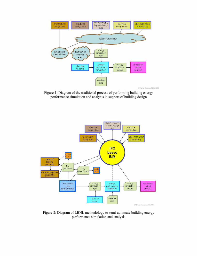
Figure 1: Diagram of the traditional process of performing building energy
performance simulation and analysis in support of building design
Figure 2: Diagram of LBNL methodology to semi-automate building energy
performance simulation and analysis
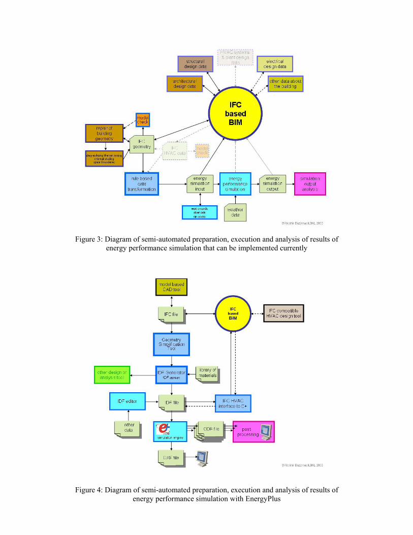
Figure 3: Diagram of semi-automated preparation, execution and analysis of results of
energy performance simulation that can be implemented currently
Figure 4: Diagram of semi-automated preparation, execution and analysis of results of energy performance simulation with EnergyPlus