Embed Size (px)
Citation preview
7/26/2019 IFR_6113E
http://slidepdf.com/reader/full/ifr6113e 1/8
For the very latest specifications visit www.aeroflex.com
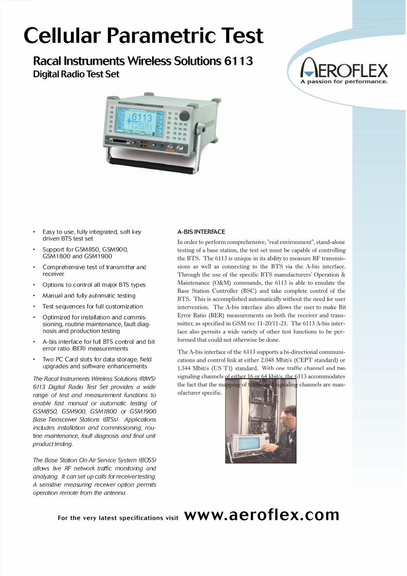
Cellular Parametric Test Racal Instruments Wireless Solutions 6113Digital Radio Test Set
• Easy to use, fully integrated, soft keydriven BTS test set
• Support for GSM850, GSM900,GSM1800 and GSM1900
• Comprehensive test of transmitter andreceiver
• Options to control all major BTS types
• Manual and fully automatic testing
• Test sequences for full customization
• Optimized for installation and commis-sioning, routine maintenance, fault diag-nosis and production testing
• A-bis interface for full BTS control and bit error ratio (BER) measurements
• Two PC Card slots for data storage, fieldupgrades and software enhancements
The Racal Instruments Wireless Solutions (RIWS)
6113 Digital Radio Test Set provides a wide
range of test and measurement functions to
enable fast manual or automatic testing of GSM850, GSM900, GSM1800 or GSM1900
Base Transceiver Stations (BTSs). Applications
includes installation and commissioning, rou-
tine maintenance, fault diagnosis and final unit
product testing.
The Base Station On-Air Service System (BOSS)
allows live RF network traffic monitoring and
analyzing. It can set up calls for receiver testing.
A sensitive measuring receiver option permits
operation remote from the antenna.
A-BIS INTERFACE
In order to perform comprehensive, "real environment", stand-alone
testing of a base station, the test set must be capable of controlling
the BTS. The 6113 is unique in its ability to measure RF transmis-
sions as well as connecting to the BTS via the A-bis interface.
Through the use of the specific BTS manufacturers' Operation &
Maintenance (O&M) commands, the 6113 is able to emulate the
Base Station Controller (BSC) and take complete control of the
BTS. This is accomplished automatically without the need for user
intervention. The A-bis interface also allows the user to make Bit
Error Ratio (BER) measurements on both the receiver and trans-
mitter, as specified in GSM rec 11-20/11-21. The 6113 A-bis inter-
face also permits a wide variety of other test functions to be per-
formed that could not otherwise be done.
The A-bis interface of the 6113 supports a bi-directional communi-
cations and control link at either 2.048 Mbit/s (CEPT standard) or
1.544 Mbit/s (US T1) standard. With one traffic channel and two
signaling channels of either 16 or 64 kbit/s, the 6113 accommodates
the fact that the mapping of traffic and signaling channels are man-
ufacturer specific.
7/26/2019 IFR_6113E
http://slidepdf.com/reader/full/ifr6113e 2/8
CODE DOWNLOAD
Code download of the manufacturer specific application files to the
BTS is another important feature of the 6113. This allows a BTS that
may not already be connected to a BSC to be tested with the same
code that will be used during normal operation, i.e. "real environ-
ment" testing.
CONFIGURATION
Configuration of the BTS can be performed by the 6113 allowing the
user to place the BTS in a state ready for testing. During testing, the6113 can control the important parameters of the BTS including;
channel number, timeslot, output power of the transmitter, receiver
diversity and the transceiver unit under test.
In addition, the 6113 extracts the BTS measurement reports (RX
LEV, RX QUAL) for the channel under test, from the A-bis interface
and reports them to the user continuously throughout the testing
process. The 6113 also displays error or fault reports that the BTS
produces on the A-bis interface.
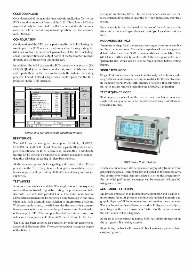
Simple and comprehensive parameter menus
RF INTERFACE
The 6113 can be configured to support GSM850, GSM900,
GSM1800 or GSM1900. The 6113 has two separate RF ports for sim-
plex connection to the BTS Receiver and Transmitter. In addition to
this the RF IN port can be configured to operate as a duplex connec-
tion, thus allowing the testing of micro base stations.
All the necessary protocols for signaling and control of the BTS are
provided in the 6113. Encryption (ciphering) is also available, export
license requirements permitting. Both A5/1 and A5/2 algorithms are
supported.
TEST MODES
A variety of test modes is available. The single test and test sequence
modes allow controlled, repeatable testing for production and fielduse, with user definable pass/fail limits. The multi-mode feature
allows all measurements to be performed simultaneously in real time,
which aids fault diagnosis and isolation of intermittent problems.
Whichever mode is used, the 6113 provides the user with a compre-
hensive range of tests to measure the performance and functionality
of the complete BTS. Wherever possible all of the tests performed are
in line with the requirements of the GSM rec. 05-05 and 11-20/11-21.
The 6113 has been designed for operation by both very experienced
and semi-skilled users alike. The experienced user has a great degree
of flexibility in
setting up and testing BTSs. The less experienced user can use the
test sequences for quick set up of the 6113 and repeatable, error free
testing.
Ease of use is further facilitated by the use of the soft keys, a spin
wheel and a numeric keypad along with a simple, logical menu struc-
ture.
PARAMETER SETTINGS
Parameter settings for all the necessary testing variants are accessible
for the experienced user. For the less experienced user a suggested
default value, based on GSM recommendations, is available. The
6113 has a further ability to store all of the set-up variables in a
"parameter file" which can be used to recall settings before testing
begins.
SINGLETEST MODE
Single Test mode allows the user to individually select from a wide
range of tests. A full range of settings is available for the user to spec-
ify including overall PASS/FAIL criteria. The test is then run with a
full set of results returned including the PASS/FAIL indication.
TEST SEQUENCE MODE
Test Sequence mode allows the user to run a complete sequence of
single tests using only one or two keystrokes, allowing controlled and
repeatable testing.
6113 Digital Radio Test Set
New test sequences can also be generated very quickly from the front
panel using a special learning facility and stored on the memory card.
Full control over which tests are selected is left to the programmer.
Further editing of the test sequences can be accomplished on a PC
using a text editor.
MULTIMODE OPERATIONMulitmode operation is an ideal tool for fault finding and isolation of
intermittent faults. It provides continuously updated numeric and
graphic displays of all the key transmitter and receiver measurements.
The graphs and graduated bar-charts aid fault diagnosis and adjust-
ment by giving the user recognizable 'pictures' of the performance of
the BTS under test as it happens.
As an aid to the operator, the normal GSM test limits are marked on
the bar-graphs. If a reading exceeds
these limits, the bar itself turns solid black making a potential fault
easily recognized.
Parameter Value
Allowed list : On, Off
RF Tests - Parameters 19 JUN 1998 12:00:00
Cancel All
All Reset
EXIT
Edit Parameter
Frequency Error Limit (+/ -) 48.00
Power Tracking On
RMS Phase Error Limit 5.00 Peak Phase Error Limit 20.00 Power Profile Mask Checking Off Mod Spectrum Mask Checking Off
Expected Power Level 0.0 Power Level Limit (+/ -) +6.0
2.000 Class Ib Limit 0.400 FER Limit 0.100
Class II Limit
Default
48.00
On
5.00 20.00
Off Off
0.0 +6.0
2.000 0.400 0.100
Hz deg deg
dBm % % %
dB
Display Holding Off Off
More...
Offsets : 0.00 dB Rslts : OFF
T.A. : RXLEV: RXQUAL:
10 MHz GPIB : 2 0
S
F
D
R
7/26/2019 IFR_6113E
http://slidepdf.com/reader/full/ifr6113e 3/8
For the very latest specifications visit www.aeroflex.com
While in Multimode, most parameters such as channel, slot number,
BTS power and RF level are easily changed. Any control commands
necessary to perform the change are automatically generated making
the 6113 very intuitive to operate.
ADDITIONALFACILITIES
INSTRUMENTCONTROL
The instrument is capable of being controlled either from the front
panel keyboard or remotely via IEEE488 GPIB interface. This allows
the test set to be included as part of a larger automatic test system.
Whichever control method is used, particular attention has been paid
to ease and speed of use.
MEMORY CARDS
The PC memory cards and hard disks provide the user with the abil-
ity to store and recall a number of instrument set-ups, test sequences
and configuration files for carrying out various tests on differing BTS
types. New test sequences can be generated from the front panel
using a special learning facility and then stored on the memory card.
In this way tests can be selected, limits and parameters changed, and
printing controlled, guaranteeing total control and repeatability of
testing.
The PCMCIA version 2 industry standard card and DOS formatting
allows direct transfer of files to a suitable PC. Two sockets are pro-
vided so that files are easily duplicated and test sequence files can
beconveniently separated from results and parameter files.
SYNCHRONIZATION OUTPUT
A programmable synchronization output allows external equipment
such as a spectrum analyzer or a logic analyzer to be triggered at any point in the GSM frame. Using this trigger signal, spurious signals
can be monitored either out-of-band or during the unused slots.
OPTIONS
The 6113 in its basic form is a complete integrated test set capable of
performing the full range of measurements on a GSM Base Station.
To complement this, RIWS can supply a range of options and acces-
sories, which significantly enhance the applications of the 6113. A full
list is provided on the back page along with ordering information.
FREQUENCY STANDARDS
Under normal circumstances the supplied frequency standard is
more than adequate, however, in a laboratory or production situation,
a higher performance may be required. The optional internal stan-
dard can achieve a stability of 0.03 ppm per year.
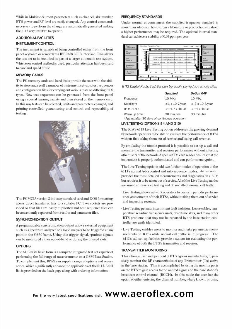
6113 Digital Radio Test Set can be easily carried to remote sites
Supplied Option 04F
Frequency 10 MHz 10 MHz
Stability*: ±1 x 10⁻⁷/year ± 3 x 10⁻⁸/year
0° to 50°C: <±1.7 x 10 -8 <±1 x 10 -8
Warm up time: 30 minutes 30 minutes*Ageing after 30 days of continuous operation
LIVETESTING (OPTIONS 54 AND 310)
The RIWS 6113 Live Testing option addresses the growing demand
by network operators to be able to evaluate the performance of BTSs
without first taking them out of service and losing call revenue.
By emulating the mobile protocol it is possible to set up a call and
measure the transmitter and receiver performance without affecting
other users of the network. A special SIM card reader ensures that the
instrument is properly authenticated and can perform encryption.
The Live Testing options add two further modes of operation to the
6113's normal A-bis control and auto sequence modes. A-bis controlprovides the most detailed measurements and diagnostics on a BTS
but requires it to be taken out of service. All of the Live Testing modes
are aimed at in-service testing and do not affect normal call traffic.
· Live Testing allows network operators to perform periodic perform-
ance assessments of their BTSs, without taking them out of service
and impacting revenue.
· Live Testing permits intermittent fault isolation. Loose cables, tem-
perature sensitive transceiver units, dead time slots, and many other
BTS problems that may not be reported by the base station con-
troller are easily identified.
· Live Testing enables users to monitor and make parametric meas-urements on BTSs while normal call traffic is in progress. The
6113's call set-up facilities provide a system for evaluating the per-
formance of both the BTS's transmitter and receiver.
TRANSMITTER MONITORING
This allows a user, independent of BTS type or manufacturer, to pas-
sively monitor the RF characteristics of any Transmitter (Tx) active
in the base station. This is accomplished by using the monitor ports
on the BTS to gain access to the wanted signal and the base station's
broadcast control channel (BCCH). In this mode the user has the
option of either entering the channel number, where known, or using
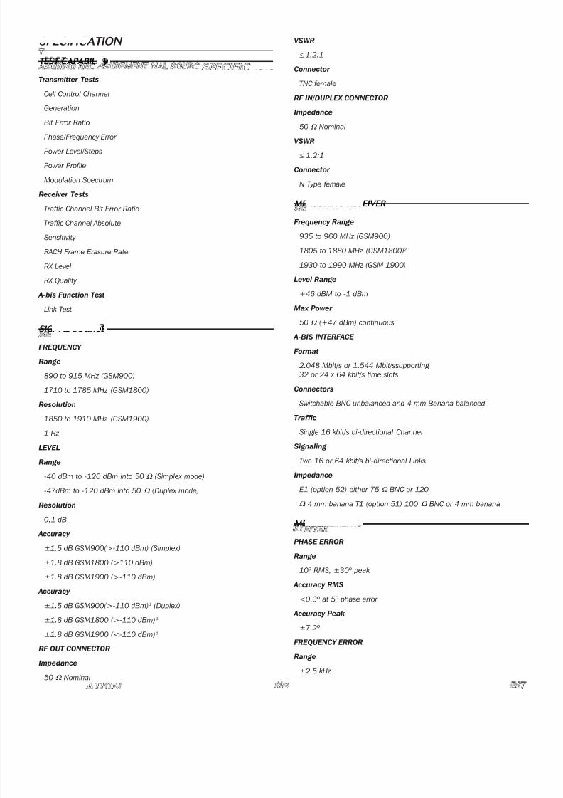
Running : Transmitter Test 19 JUN 1998 10:10:19
EXIT
Edit
Repeat
Full
Screen
Horizontal
-10 : +155
Vertical
dB -70 : +10
Test Status FAIL - Measured values exceed tes t limits
Error Phase
Modulation Spectrum
Test
Stop /
Test Resul ts
Test Information
10
Bits
0
-10
-20
-30
-40
0 20 40 60 80 100 120 140
d B
-50
-60
-70
(The Power Profile mask varies according to the type of
BTS, and according to type of channel - i.e. BCCH or TCH.
Refer to Section 7 Manufacturer -Specific Information
for details).
Configure Printer
Offsets : 0.00 dB Rslts : OFF
T.A. : RXLEV: RXQUAL:
10 MHz GPIB : 20
S
F
D
R

7/26/2019 IFR_6113E
http://slidepdf.com/reader/full/ifr6113e 4/8
the 6113's unique scanning feature to locate the CCH and any asso-
ciated traffic channels. Once located, the 6113 will automatically lock
on and decode it. The 6113 will then non-intrusively monitor all of the
following parameters on any selected channel and time slot.
· Transmitter power and power profile
· RMS phase error
· Peak phase error
· Frequency error (Relative to the 6113 time base)
· Modulation spectrum
The measurements are displayed as precise numerical readings along
with easy to read bar graphs. Exceeding the recommended limits
causes the bar to change color, quickly high-lighting a possible fault
condition.
FULL CALL SET UP, RECEIVER SENSITIVITY
Measurement Once the performance of the transmitters has been
verified, the next logical step is to check the operation of the receivers.
As with any digital receiver testing, this is accomplished with a bit
error ratio (BER) measurement.Using the call set-up facilities of the 6113 a call is established using a
normal network SIM. Once a traffic channel has been assigned, the
instrument can then inject a variety of test patterns. Using the high
impedance A-bis input, the entire receiver traffic is monitored and
the test pattern automatically located. Once synchronized, a contin-
uous BER reading is available. The signal level seen
by the receiver can then be varied manually or automatically to deter-
mine the sensitivity.
For more detailed information there is also available a separate menu
displaying the FER, Class Ib and Class II Minimum, Maximum and
Mean BER readings.
LIVETESTING OPTIONS
Two Live Testing options are offered for the 6113. The first (Option
310) provides just the software associated with call setup and Live
Testing, this is useful where individual transceivers can be isolated
such as when testing microcells and where a low loss RF connection
can be made to the base station.
A second option (Option 54) adds a sensitive and selective receiver
unit, which then allows the instruments to discriminate the want-
ed signal from nearby unwanted signals, and additional gain compen-
sates for a significant path loss. It is also available as a retrofit option
for existing 6113 users. (Note: Option 310 is always included withoption 54).
CELL INTEGRITY (OPTION 311)
The Cell Integrity Test Suite provides important new functionality for
the RIWS 6113 GSM digital radio BTS test set. This new software
allows the user to assess the total integrity of a complete cell site, and
will normally form part of the complete commissioning and integra-
tion procedure.
Whilst the 6113 when in A-bis Control Mode allows the user to check
the performance of the complete BTS, the new Cell Integrity Test
Suite allows the user to assess the performance of the site as a whole,
including the antennas, masthead amplifiers, interconnecting cables,
etc.
It is also possible to monitor the performance of the site from any
point within the cell coverage area using the Cell Integrity Test Suite
automated functions. The 6113 emulates all the network functionali-
ty required to make these tests, thus obviating the necessity for an A-
bis connection to the network BSC.
The only additional equipment required to carry out these cell per-
formance checks are a standard GSM mobile handset (supplied), a
valid network SIM card and a RIWS CIT SIM card (supplied).
MAIN FEATURES
The user may check the following aspects of a GSM based cell site:
· Integrity and correct connection of all cell antennas, masthead
amplifiers and cabling.
· Quality of speech using a standard mobile terminal.
· Automated sequential call placement utilizing all timeslots* and all
carriers.
· Combined uplink and downlink BER measurements.· Comparison of uplink and downlink losses over the air.
· Equalization of uplink and downlink losses - cell or antenna balanc-
ing. (Worldwide patents pending)
*with the exception of timeslot 0
BRIEFTEST SUMMARY
The following tests are available within the RIWS Cell Integrity Test
Suite for the 6113.
· 6113 Originated Call with Mobile Audio Loopback (using Racal
Instruments test SIM)
· 6113 Originated Call with Audio Loopback.
· 6113 Originated Call with Audio Loopback AND Mobile Audio
Loopback (using Racal Instruments test SIM)
· Mobile Originated Call with Mobile Audio Loopback (using Racal
Instruments test SIM)
· Mobile Originated Call with Audio Loopback
· Mobile Originated Call with Audio Loopback AND Mobile Audio
Loopback (using Racal Instruments test SIM)
· Antenna Balancing
DETAILED TEST DESCRIPTIONS
Please refer to the diagram below for details of test equipment con-
nections. It can be seen that the 6113 acts as a BSC or network sim-
ulator that has full control of the BTS. No RF connections are made
to the 6113. All antennas and external equipment are connected to the
BTS as normal.

7/26/2019 IFR_6113E
http://slidepdf.com/reader/full/ifr6113e 5/8
For the very latest specifications visit www.aeroflex.com
6113 ORIGINATED CALL WITH MOBILE AUDIO LOOPBACK
(USING RIWS TESTSIM)The 6113 instructs the BTS to generate a combined BCCH on the
ARFCN selected by the user and at a user defined power level.The
system information for the control channel is derived from the infor-
mation in the 6113's GSM parameter settings. The user is prompted
to switch on the mobile handset, which then registers to the '6113
network', provided that its IMSI and IMEI have been correctly entered
in the 6113 test parameters menu. The cell is barred to all users
except those defined by the user in the test parameters for this func-
tion.
Following registration, the mobile is paged and a call is assigned to
the selected timeslot, or timeslot 1 if automatic testing on all times-
lots has been previously selected as a test parameter.
The mobile is instructed to loop back the traffic frames and a BER
test is performed for the specified duration, during which the inter-
im BER
measurements are displayed together with the uplink RXLEV reports,
the uplink RXQUAL reports, the downlink RXLEV reports and the
downlink RXQUAL reports. Upon completion of the test, the call is
terminated. If all timeslots have been selected for testing, subsequent
calls are made automatically, checking each timeslot in turn.
This test may be fully automated if the mobile handset is configured
for auto-answer mode.
6113 ORIGINATED CALL WITH AUDIO LOOPBACK.
This test allows the user to assess the voice quality of the air inter-
face link between the BTS and the mobile handset. Registration and
call set up are performed in an identical manner to the test detailed
above. Once the call is in progress, the 6113 will loop back the traffic
frames to the mobile, after a defined period of delay, thus allowing the
user to assess the quality of the link. If all timeslots have been previ-
ously selected for testing, the caller will be paged on the next untest-
ed timeslot each time a call is terminated until all timeslots have been
tested.
6113 ORIGINATED CALL WITH AUDIO LOOPBACK AND
MOBILE AUDIO LOOPBACK (USING RIWS TEST SIM)
Registration and call set up are completed in the manner described
above. This test is a concatenation of the previous two tests. During
the first stage, a BER test is run with audio loopback activated within
the mobile handset. When this is complete, loopback is removed from
the mobile and applied to the 6113, allowing voice quality assessment
to be made. Sequential testing of all timeslots is performed in a man-
ner similar to that described above.
MOBILE ORIGINATED CALLWITH MOBILE AUDIO LOOPBACK
(USING RIWS TESTSIM)
Registration is performed in the manner described above. The 6113
now waits for a mobile originated call. A simple coding system allows
the user to select from the mobile keypad the timeslot number to be
assigned by the 6113 for the call. A BER test is then performed for the
duration specified by the user.
MOBILE ORIGINATED CALL WITH AUDIO LOOPBACK
Registration is performed in the manner described above. The 6113
now waits for a mobile originated call. A simple coding system allows
the user to select from the mobile keypad the timeslot number to be
assigned by the 6113 for the call. The 6113 will loop back traffic
frames such that the user may assess the quality of the speech
received at the mobile terminal.
MOBILE ORIGINATED CALL WITH AUDIO LOOPBACK AND
MOBILE AUDIO LOOPBACK (USING RIWS TEST SIM)
Registration and call set up are completed in the manner described
above. This test is a concatenation of the previous two tests. During
the first stage, a BER test is run with audio loopback activated within
the mobile handset. When this is complete, loopback is removed from
the mobile and applied to the 6113, allowing voice quality assessment
to be made. Sequential testing of all timeslots is performed in a sim-
ilar manner to that described above.
EDGE (OPTION 440)
Option 440 adds the ability to test EDGE enabled base stations.
In addition to the current GSM channel types, the following
(E)GPRS channel types are also supported:
· CS-1 to CS-4 (GMSK)
· MCS-1 to MCS-4 (GMSK)
· MCS-5 to MCS-9 (8PSK)
For full details, please refer to the separate 6113 EDGE product infor-
mation.
A-bis
Antenna
mast
Standard mobile
with RIWS test
SIM
BTS
6113
7/26/2019 IFR_6113E
http://slidepdf.com/reader/full/ifr6113e 6/8
SPECIFIC ATION
T EST C APABILI T Y
Transmitter Tests
Cell Control Channel
Generation
Bit Error Ratio
Phase/Frequency Error
Power Level/Steps
Power Profile
Modulation Spectrum
Receiver Tests
Traffic Channel Bit Error Ratio
Traffic Channel Absolute
Sensitivity
RACH Frame Erasure Rate
RX Level
RX Quality
A-bis Function Test
Link Test
SIG NAL SOURC E
FREQUENCY
Range
890 to 915 MHz (GSM900)
1710 to 1785 MHz (GSM1800)
Resolution
1850 to 1910 MHz (GSM1900)
1 Hz
LEVEL
Range
-40 dBm to -120 dBm into 50 Ω (Simplex mode)
-47dBm to -120 dBm into 50 Ω (Duplex mode)
Resolution
0.1 dB
Accuracy
±1.5 dB GSM900(>-110 dBm) (Simplex)
±1.8 dB GSM1800 (>110 dBm)
±1.8 dB GSM1900 (>-110 dBm)
Accuracy
±1.5 dB GSM900(>-110 dBm)1 (Duplex)
±1.8 dB GSM1800 (>-110 dBm)1
±1.8 dB GSM1900 (<-110 dBm)1
RF OUT CONNECTOR
Impedance
50 Ω Nominal
VSWR
≤ 1.2:1
Connector
TNC female
RF IN/DUPLEX CONNECTOR
Impedance
50 Ω Nominal
VSWR
≤ 1.2:1
Connector
N Type female
ME ASURING REC EIVER
Frequency Range
935 to 960 MHz (GSM900)
1805 to 1880 MHz (GSM1800)2
1930 to 1990 MHz (GSM 1900)
Level Range
+46 dBM to -1 dBm
Max Power
50 Ω (+47 dBm) continuous
A-BIS INTERFACE
Format
2.048 Mbit/s or 1.544 Mbit/ssupporting
32 or 24 x 64 kbit/s time slots
Connectors
Switchable BNC unbalanced and 4 mm Banana balanced
Traffic
Single 16 kbit/s bi-directional Channel
Signaling
Two 16 or 64 kbit/s bi-directional Links
Impedance
E1 (option 52) either 75 Ω BNC or 120
Ω 4 mm banana T1 (option 51) 100 Ω BNC or 4 mm banana
ME ASUREMENT S
PHASE ERROR
Range
10º RMS, ±30º peak
Accuracy RMS
<0.3º at 5º phase error
Accuracy Peak
±7.2º
FREQUENCY ERROR
Range
±2.5 kHz
7/26/2019 IFR_6113E
http://slidepdf.com/reader/full/ifr6113e 7/8
For the very latest specifications visit www.aeroflex.com
Accuracy
4.5 Hz + freq. std³.
POWER LEVEL
Range
±46 dBm to -1 dBm
Absolute Accuracy
±1.0 dB (GSM900)
±1.0 dB (GSM1800, =20W)
±1.2 dB (GSM1900, =20W)
Relative Accuracy
<±0/.4 dB
POWER PROFILE
Dynamic Range
>48 dB²
MODULATION SPECTRUM
Dynamic Range
>52 dB³
Frequency Span
1 MHz
FREQUENCY STANDARD
Internal
±1.2 x 10⁻⁷ (standard)4
(1 Year, all sources of error) ±3.5 x 10⁻⁸ (Option 04F)4
External frequencies:
10 MHz or 13 MHz ± 2.5 ppm-2 dBm to +19 dBm into 50 Ω
Reference Output:
10 MHz or 13 MHz +9 dBm nominal into 50 Ω
I NT ERFAC ES
Memory Card
2 Sockets, PCMCIA V2.0
Card Size
Type1, 2 or 3
Card Types supported
SRAM, ATA Flash EEPROM And hard discs
Synchronization Output
For synchronizing external equipment such as a spectrum analyzer
GPIB:
ANSI/IEEE 488.2 - 1987
Compatibility Subset
SH1, AH1, T5, L4, SR1, RL1 PP0, DC1, DT0, C0, E1
RS232 Interfaces
2 configurable ports for printing and Control 9 way male D-Type
Parallel Printer
25 way female D-Type
BT S M ANUFACT URERS SU P PORT ED
Alcatel
Ericsson
Interwave
Italtel
Motorola
Nokia
Nortel
PKI
Siemens
GENE R AL
Voltage ranges
85 to 13V and 180 to 264V AC
Frequency range
45 to 66 Hz
Power consumption
170 VA maximum
DIMENSIONS AND ENVIRONMENT
Height
210 mm
Width
350 mm
Depth
420 mm
Weight
14 kg approx
Operating Temperature
0 to 50°C
Calibration Period
1 year
EMC
Complies with
BS EN50081-1 (emissions)
BS EN50082-1 (immunity)
Safety
Complies with BS EN61010-1
U P DAT E P ROGRAMS
Aeroflex offers a comprehensive software maintenance and enhance-
ment program. This means that as new BTS software versions are
released the test capability of the 6113 can be updated in line with
any changes. Adding new BTS software versions or updating existing
software features of the 6113 can be performed quickly and easily in
the field via memory card, IEEE488 or RS232 interface.
Aeroflex has a policy of continuous improvements which means that
specifications will change. For full details of 6113 capabilities and BTS
support options, contact your local Aeroflex office.
7/26/2019 IFR_6113E
http://slidepdf.com/reader/full/ifr6113e 8/8
VERSIONS AND ACCESSORIES
When ordering please quote the full ordering number information.
ORDERING INF ORM AT ION
Model 6113 BTS Test Set
Model 6113E BTS Test Set with encryption, option 10R
Option 01 GSM900 operation*
Option 02 GSM1800 operation*
Option 03 GSM1900 operation*
Option 04F Very High Stability Frequency Standard
Option 08 GSM 850 Operation
Option 10R Encryption retrofit kit
Option 51 T1 A-bis Interface†
Option 52 E1 A-bis Interface†
Option 60 Rack Mounting
Option 61 Padded Carrying Bag
Option 62 Rigid Transit Case
Option 64 Front Panel Protection Cover
Option 70 GSM/DCS1800/PCS1800 test SIM for test set
Option 71 Miniature SIM adaptor for test set
Option 76 Memory Card, 256 kbyte
Option 77 Memory Card, 2 Mbyte
Option 78 Flash Memory Card, 10M byte
Option 79 Removable Hard Disk Drive 1 Gb
Option 90 Test Set/PC RS232 download cable, (9 way D-type)
Option 91 Test Set/Printer RS232 cable (25 way D-type)
Option 92 Test Set/Printer parallel cable
*A least one of the option 01,02,03 must be ordered with the basic
model and options 02 and 03 cannot be installed together.
†At least one of option 51 or 52 must be ordered with the basic model
MAN UFACT URE R S P EC IFIC SOF T WARE
Option 220 Ericsson Software
Option 230 Italtel Software
Option 235 Siemens Software
Option 250 Nortel Software
Option 255 Motorola Software
Option 270 Nokia Software
Option 275 Alcatel Software
Option 280 Lucent Software
Option 285 Interwave Software
Option 300 AIME Software - Air Interface Monitor and Emulator
Software
Option 310 LIVE Testing
Option 311 Cell Integrity Testing Software
SUP PORT OPTIONS
A number of support options are available that ensure equipment is
kept up to date and calibrated. Software support ensures that the lat-
est software is provided. This is important where base station softwareis revised by the base station manufacturer, and where new features
and enhancements are made available.
Extended warranty and calibration is also available. Request Product
Support Information data for full details.
Option S1 One year Software Support
Option S2 Two year Software Support
Option S3 Three year Software Support
Option C1 One annual calibration
Option C2 Two annual calibrations
Option E2 One year extended warranty
Option E3 Two year extended warranty
Option W2 One year extended warranty with calibration
Option W3 Two year extended warranty with calibrations
Part No. 46891/192, Issue 1, 04/05
CHINA Beijing
Tel: [+86] (10) 646727612716Fax: [+86] (10) 6467 2821
CHINA Shanghai
Tel: [+86] (21) 62828001
Fax: [+86] (21) 62828 8002
FINLAND
Tel: [+358] (9) 2709 5541
Fax: [+358] (9) 804 2441
FRANCE
Tel: [+33] 160 79 96 00
Fax: [+33] 160 7769 22
GERMANY
Tel: [+49] 81312926-0Fax: [+49] 8131 2926-130
HONG KONG
Tel: [+852] 2832 7988
Fax: [+852] 2834 5364
INDIA
Tel: [+91] 80 5115 4501
Fax: [+91] 80 5115 4502
KOREA
Tel: [+82] (2) 3424 2719
Fax: [+82] (2) 3424 8620
SCANDINAVIA
Tel: [+45] 9614 0045Fax: [+45] 9614 0047
SPAIN
Tel: [+34] (91) 640 11 34
Fax: [+34] (91) 640 06 40
UK Burnham
Tel: [+44] (0) 1628 604455
Fax: [+44] (0) 1628 662017
UK Stevenage
Tel: [+44] (0) 1438 742200Fax: [+44] (0) 1438 727601
Freephone: 0800 282388
USA
Tel: [+1] (316) 522 4981
Fax: [+1] (316) 522 1360
Toll Free: 800 835 2352
w w w . a e r o f l e x . c o m
i n f o - t e s t @ a e r o f l e x . c o m
As we are always seeking to improve our products,
the information in this document gives only a general
indication of the product capacity, performance and
suitability, none of which shall form part of any con-
tract. We reserve the right to make design changes
without notice. All trademarks are acknowledged.
Parent company Aeroflex, Inc. ©Aeroflex 2005.
Our passion for performance is defined by three
attributes represented by these three icons:
solution-minded, performance-driven and customer-focused.


